US9830486B2 - RFID variable aperture read chamber crossfire - Google Patents
RFID variable aperture read chamber crossfireDownload PDFInfo
- Publication number
- US9830486B2 US9830486B2US14/584,518US201414584518AUS9830486B2US 9830486 B2US9830486 B2US 9830486B2US 201414584518 AUS201414584518 AUS 201414584518AUS 9830486 B2US9830486 B2US 9830486B2
- Authority
- US
- United States
- Prior art keywords
- read
- antenna
- enclosure
- chamber device
- movable plate
- Prior art date
- Legal status (The legal status is an assumption and is not a legal conclusion. Google has not performed a legal analysis and makes no representation as to the accuracy of the status listed.)
- Active
Links
Images

Classifications
- G—PHYSICS
- G06—COMPUTING OR CALCULATING; COUNTING
- G06K—GRAPHICAL DATA READING; PRESENTATION OF DATA; RECORD CARRIERS; HANDLING RECORD CARRIERS
- G06K7/00—Methods or arrangements for sensing record carriers, e.g. for reading patterns
- G06K7/10—Methods or arrangements for sensing record carriers, e.g. for reading patterns by electromagnetic radiation, e.g. optical sensing; by corpuscular radiation
- G06K7/10009—Methods or arrangements for sensing record carriers, e.g. for reading patterns by electromagnetic radiation, e.g. optical sensing; by corpuscular radiation sensing by radiation using wavelengths larger than 0.1 mm, e.g. radio-waves or microwaves
- G06K7/10366—Methods or arrangements for sensing record carriers, e.g. for reading patterns by electromagnetic radiation, e.g. optical sensing; by corpuscular radiation sensing by radiation using wavelengths larger than 0.1 mm, e.g. radio-waves or microwaves the interrogation device being adapted for miscellaneous applications
- G06K7/10415—Methods or arrangements for sensing record carriers, e.g. for reading patterns by electromagnetic radiation, e.g. optical sensing; by corpuscular radiation sensing by radiation using wavelengths larger than 0.1 mm, e.g. radio-waves or microwaves the interrogation device being adapted for miscellaneous applications the interrogation device being fixed in its position, such as an access control device for reading wireless access cards, or a wireless ATM
- G06K7/10425—Methods or arrangements for sensing record carriers, e.g. for reading patterns by electromagnetic radiation, e.g. optical sensing; by corpuscular radiation sensing by radiation using wavelengths larger than 0.1 mm, e.g. radio-waves or microwaves the interrogation device being adapted for miscellaneous applications the interrogation device being fixed in its position, such as an access control device for reading wireless access cards, or a wireless ATM the interrogation device being arranged for interrogation of record carriers passing by the interrogation device
- G06K7/10435—Methods or arrangements for sensing record carriers, e.g. for reading patterns by electromagnetic radiation, e.g. optical sensing; by corpuscular radiation sensing by radiation using wavelengths larger than 0.1 mm, e.g. radio-waves or microwaves the interrogation device being adapted for miscellaneous applications the interrogation device being fixed in its position, such as an access control device for reading wireless access cards, or a wireless ATM the interrogation device being arranged for interrogation of record carriers passing by the interrogation device the interrogation device being positioned close to a conveyor belt or the like on which moving record carriers are passing
- B—PERFORMING OPERATIONS; TRANSPORTING
- B65—CONVEYING; PACKING; STORING; HANDLING THIN OR FILAMENTARY MATERIAL
- B65G—TRANSPORT OR STORAGE DEVICES, e.g. CONVEYORS FOR LOADING OR TIPPING, SHOP CONVEYOR SYSTEMS OR PNEUMATIC TUBE CONVEYORS
- B65G43/00—Control devices, e.g. for safety, warning or fault-correcting
- G—PHYSICS
- G06—COMPUTING OR CALCULATING; COUNTING
- G06K—GRAPHICAL DATA READING; PRESENTATION OF DATA; RECORD CARRIERS; HANDLING RECORD CARRIERS
- G06K7/00—Methods or arrangements for sensing record carriers, e.g. for reading patterns
- G06K7/10—Methods or arrangements for sensing record carriers, e.g. for reading patterns by electromagnetic radiation, e.g. optical sensing; by corpuscular radiation
- G06K7/10009—Methods or arrangements for sensing record carriers, e.g. for reading patterns by electromagnetic radiation, e.g. optical sensing; by corpuscular radiation sensing by radiation using wavelengths larger than 0.1 mm, e.g. radio-waves or microwaves
- G06K7/10366—Methods or arrangements for sensing record carriers, e.g. for reading patterns by electromagnetic radiation, e.g. optical sensing; by corpuscular radiation sensing by radiation using wavelengths larger than 0.1 mm, e.g. radio-waves or microwaves the interrogation device being adapted for miscellaneous applications
- G06K7/10415—Methods or arrangements for sensing record carriers, e.g. for reading patterns by electromagnetic radiation, e.g. optical sensing; by corpuscular radiation sensing by radiation using wavelengths larger than 0.1 mm, e.g. radio-waves or microwaves the interrogation device being adapted for miscellaneous applications the interrogation device being fixed in its position, such as an access control device for reading wireless access cards, or a wireless ATM
- G06K7/10425—Methods or arrangements for sensing record carriers, e.g. for reading patterns by electromagnetic radiation, e.g. optical sensing; by corpuscular radiation sensing by radiation using wavelengths larger than 0.1 mm, e.g. radio-waves or microwaves the interrogation device being adapted for miscellaneous applications the interrogation device being fixed in its position, such as an access control device for reading wireless access cards, or a wireless ATM the interrogation device being arranged for interrogation of record carriers passing by the interrogation device
- G06K7/10435—Methods or arrangements for sensing record carriers, e.g. for reading patterns by electromagnetic radiation, e.g. optical sensing; by corpuscular radiation sensing by radiation using wavelengths larger than 0.1 mm, e.g. radio-waves or microwaves the interrogation device being adapted for miscellaneous applications the interrogation device being fixed in its position, such as an access control device for reading wireless access cards, or a wireless ATM the interrogation device being arranged for interrogation of record carriers passing by the interrogation device the interrogation device being positioned close to a conveyor belt or the like on which moving record carriers are passing
- G06K7/10445—Methods or arrangements for sensing record carriers, e.g. for reading patterns by electromagnetic radiation, e.g. optical sensing; by corpuscular radiation sensing by radiation using wavelengths larger than 0.1 mm, e.g. radio-waves or microwaves the interrogation device being adapted for miscellaneous applications the interrogation device being fixed in its position, such as an access control device for reading wireless access cards, or a wireless ATM the interrogation device being arranged for interrogation of record carriers passing by the interrogation device the interrogation device being positioned close to a conveyor belt or the like on which moving record carriers are passing the record carriers being fixed to further objects, e.g. RFIDs fixed to packages, luggage, mail-pieces or work-pieces transported on a conveyor belt
- H—ELECTRICITY
- H01—ELECTRIC ELEMENTS
- H01Q—ANTENNAS, i.e. RADIO AERIALS
- H01Q17/00—Devices for absorbing waves radiated from an antenna; Combinations of such devices with active antenna elements or systems
Definitions
- the present inventionrelates generally to radio frequency identification (RFID) systems and devices. More particularly, the present disclosure relates to systems and devices for further confining and focusing radio frequency energy when applied with the use of RFID transponders that are moving in high speed linear motion through use of a conveyance to allow for the singulation of carton contents.
- RFIDradio frequency identification
- Radio frequency identification (RFID) tagsare electronic devices that may be affixed to items whose presence is to be detected and/or monitored. The presence of an RFID tag, and therefore the presence of the item to which the RFID tag is affixed, may be checked and monitored by devices known as “readers” or “reader panels.” Readers typically transmit radio frequency signals to which the RFID tags respond. Each RFID tag can store a unique identification number. The RFID tags respond to reader-transmitted signals by providing their identification number and additional information stored on the RFID tag based on a reader command to enable the reader to determine an identification and characteristics of an item.
- an enclosureuses a combination of absorber material to attenuate radio frequency energy and a read chamber central to the enclosure that projects a read zone.
- the read chamberuses an absorber method that directs the main flow of energy normal to the antenna plane, creating the read zone.
- thisdoes create a field or read zone, it does not allow for tuning of the read zone.
- Refinement (or tuning) of the leading edge signal of the read zoneis critical to the success of reducing the overall gap or spacing required between cartons.
- some degree of tuningcan be done by means of power modulation to the antenna contained within the read chamber. However, this is only marginally effective as a function of the power decreases so does the effectiveness of the reader to energize the transponders.
- the present inventiondiscloses a read chamber device that provides for tuning (or reducing) the read zone via a movable metal plate that is positioned at variable distances to partially or fully cover the read zone.
- the metal plateis moved into the read zone to obstruct a percentage of radio frequency energy from escaping the read zone, and thus narrowing the total read field and refining the leading edge signal of the read zone.
- the disclosed read chamber devicedoes not require power modulation for tuning and allows the use of high reader power without causing an extension of the RF field beyond a defined area.
- the read chamber devicein combination with the use of metallic and absorption materials allows for the singulation of carton contents.
- the subject matter disclosed and claimed hereinin one aspect thereof, comprises a read chamber device for use within a radio frequency identification (RFID) scanning enclosure (or tunnel) which provides a means of reading a plurality of cartons moving through the enclosure via a conveyor belt.
- RFIDradio frequency identification
- the RFID scanning enclosureis positioned over a section of the conveyor belt, such that the plurality of cartons on the conveyor belt pass directly through the RFID scanning enclosure.
- the read chamber deviceis positioned within the enclosure and projects a read zone via an antenna positioned centrally within the read chamber device.
- the read chamber deviceprovides for tuning (or reducing) the read zone via a movable metal plate that is positioned at variable distances to partially or fully cover the read zone.
- the metal plateis moved into the read zone to obstruct a percentage of radio frequency energy from escaping the read zone, and thus narrowing the total read field.
- the metal platecomprises absorber material components secured to its surface to cancel a portion of the signal and prevent it from propagating back to the face of the antenna which emits the radio frequency signal.
- the variability of the metal plateallows for tuning of the intended read zone along the line of conveyance which allows for isolation of groups of transponders from one carton to the next.
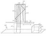
- FIG. 1illustrates a top view of the read chamber device and RFID scanning enclosure in accordance with the disclosed architecture.
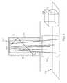
- FIG. 2illustrates a top view of the read chamber device with moveable metal plates for tuning the read zone in accordance with the disclosed architecture.
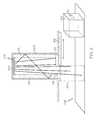
- FIG. 3illustrates a method of moving containers through a read chamber device and RFID scanning enclosure in accordance with the disclosed architecture.
- the present inventiondiscloses a read chamber device that provides for tuning (or reducing) the read zone via a movable metal plate that is positioned at variable distances to partially or fully cover the read zone.
- the metal plateis moved into the read zone to obstruct a percentage of radio frequency energy from escaping the read zone, and thus narrowing the total read field and refining the leading edge signal of the read zone.
- the read chamber devicedoes not require power modulation for tuning and allows the use of high reader power without causing an extension of the RF field beyond a defined area.
- the read chamber devicein combination with the use of metallic and absorption materials allows for the singulation of carton contents.
- the present inventioncontemplates that the size of the RF field of the present invention is variable and is not limited to the reading of a singular carton but may be extended to a plurality of cartons if so desired.
- the read chamber deviceis disclosed for use within a radio frequency identification (RFID) scanning enclosure.
- the enclosureis positioned over a section of the conveyor belt, such that the plurality of cartons on the conveyor belt pass directly through the enclosure.
- the read chamber devicemay be positioned centrally to the enclosure and projects a read zone via an antenna positioned centrally within the read chamber device.
- the read chamber deviceprovides for tuning the read zone via a movable metal plate comprising absorber material components secured to it that is positioned at variable distances to partially or fully cover the read zone. The metal plate is moved into the read zone to obstruct a percentage of radio frequency energy from escaping the read zone, and thus narrowing the total read field.
- FIG. 1illustrates a read chamber device 100 for use within a radio frequency identification (RFID) scanning enclosure (or tunnel) 102 which provides a means of reading a plurality of cartons 104 moving through the enclosure 102 .
- RFIDradio frequency identification
- the RFID scanning enclosure 102is positioned over a section of the conveyor belt 106 , such that the plurality of cartons 104 on the conveyor belt 106 pass directly through the RFID scanning enclosure 102 .
- a barcode scanneris located within the RFID scanning enclosure 102 .
- an antenna 108projects radio frequency energy to create a read zone 110 for the reader.
- RFID tags 112 (or transponders) on the cartons 104are energized and read in the read zone 110 by the reader and signals are transmitted back to the reader, identifying the carton 104 and transmitting any other information the tags 112 might contain.
- RFID tags 112or transponders
- the enclosure 102 to read RFID tags 112 on cartons 104is merely one possible example and the same system may be used for any application that involves a reading of any group of items that are streaming through a particular location.
- the term “carton”is used throughout the present disclosure for exemplary purposes, the term “carton” may be any single item or a group of items.
- the RFID scanning enclosure 102can be any suitable size, shape, and configuration as is known in the art without affecting the overall concept of the invention.
- One of ordinary skill in the artwill appreciate that the interior and/or exterior shape of the enclosure 102 as shown in FIGS. 1 and 2 is for illustrative purposes only and many other shapes of the enclosure 102 , such as a cylinder or a rectangle, are well within the, scope of the present disclosure.
- dimensions of the enclosure 102i.e., length, width, and height
- the enclosure 102may be any shape that ensures an optimal read zone 110 toward a carton 104 within the enclosure 102 .
- the RFID scanning enclosure 102comprises a tunnel throat (or opening) 114 wherein cartons 104 enter the enclosure 102 via the conveyor belt 106 .
- the tunnel opening 114is designed to deal with motility and movement of the conveyor belt 106 the products or cartons 104 are traveling on.
- the tunnel openingcan have a throat capacity of approximately 24′′ or 36′′.
- the scanning enclosure 102comprises a read chamber device 100 .
- the read chamber device 100is positioned centrally to the enclosure 102 and projects a read zone 110 via at least one antenna 108 .
- an antenna 108is positioned centrally within the read chamber device 100 and projects radio frequency energy from a front plane of the antenna 108 .
- Any suitable number of antennas 108can be used as is known in the art, depending on the wants and needs of a user and the configuration of the enclosure 102 .
- any suitable type of antennacan be used as is known in the art, such as a wide angle antenna, wide angle antenna, circular, linear, dipole, etc., depending on the wants and needs of a user and the configuration of the enclosure 102 .
- Energy projected straight forward from the front plane of the antenna(s) 108is carried forward without obstruction creating the read zone 110 .
- absorber material components 115are secured on either side of the antenna 108 and on the side walls of the read chamber device 100 .
- the absorber material components 115typically comprise absorber material components 115 typically comprise some kind of graphite impregnated material or other absorption technique for subduing the propogation of RF energy, though any other suitable material can be used as is known in the art.
- the absorber material components 115are typically secured to the sides and side walls of the read chamber device 100 via any suitable securing means as is known in the art.
- energy projected (or leaked) to the sides of the front plane of the antenna 108is canceled through the use of the absorber material components 115 to create a fixed read zone 110 (defined or fixed width for the read zone). Accordingly, cartons 104 (and their transponders or tags 112 ) entering the fixed read zone 110 are detected and read by the reader and information contained within the tags 112 is transmitted to the reader.
- FIG. 2illustrates a read chamber device 200 for use within a radio frequency identification (RFID) scanning enclosure (or tunnel) 202 which provides a means of reading a plurality of cartons 204 moving through the enclosure 202 and allows for tuning (or reducing) the read zone 210 .
- RFIDradio frequency identification
- the plurality of cartons 204move through the enclosure 202 via a conveyor belt 206 or other transport mechanism as is known in the art.
- the RFID scanning enclosure 202is positioned over a section of the conveyor belt 206 , such that the plurality of cartons 204 on the conveyor belt 206 pass directly through the RFID scanning enclosure 202 .
- an antenna 208projects radio frequency energy to create a read zone 210 for the reader.
- RFID tags 212(or transponders) on the cartons 204 are energized and read in the read zone 210 by the reader and signals are transmitted back to the reader, identifying the carton 204 and transmitting any other information the tags 212 might contain.
- the RFID scanning enclosure 202comprises a tunnel throat (or opening) 214 wherein cartons 204 enter the enclosure 202 via the conveyor belt 206 .
- the tunnel opening 214is designed to deal with motility and movement of the conveyor belt 206 the products or cartons 204 are traveling on.
- the tunnel openingcan have a throat capacity of approximately 24′′ or 36′′.
- the scanning enclosure 202comprises a read chamber device 200 .
- the read chamber device 200is positioned centrally to the enclosure 202 and projects a read zone 210 via at least one antenna 208 .
- an antenna 208is positioned centrally within the read chamber device 200 and projects radio frequency energy from a front plane of the antenna 208 .
- Any suitable number of antennas 208can be used as is known in the art, depending on the wants and needs of a user and the configuration of the enclosure 202 .
- any suitable type of antennacan be used as is known in the art, such as a wide angle antenna, wide angle antenna, circular, linear, dipole etc., depending on the wants and needs of a user and the configuration of the enclosure 202 .
- Energy projected straight forward from the front plane of the antenna(s) 208is carried forward without obstruction creating the read zone 210 .
- absorber material components 215are secured on either side of the antenna 208 and on the side walls of the read chamber device 200 .
- the absorber material components 215typically comprise absorber material components 115 typically comprise some kind of graphite impregnated material or other absorption technique for subduing the propogation of RF energy, though any other suitable material can be used as is known in the art.
- the absorber material components 215are typically secured to the sides and side walls of the read chamber device 200 via any suitable securing means as is known in the art.
- energy projected (or leaked) to the sides of the front plane of the antenna 208is canceled through the use of the absorber material components 215 to create a fixed read zone 210 (defined or fixed width for the read zone). Accordingly, cartons 204 (and their transponders or tags 212 ) entering the fixed read zone 210 are detected and read by the reader and information contained within the tags 212 is transmitted to the reader.
- the read chamber device 200 of FIG. 2provides for tuning (or reducing) the read zone 210 .
- the read chamber device 200creates refinement in the leading edge of the read zone 210 where first detection of transponders is most critical. This leading edge is what defines the minimum carton spacing required to achieve isolation of the transponders.
- the transponders (or RFID inlays) in the cartons 204 that are usedare forced into stasis once read by the reader, such that those transponders will no longer be seen by the reader until they have exited the entire enclosure 202 .
- Some degree of tuningcan take place by means of power modulation to the antenna(s) 208 contained within the read chamber device 200 . However, this is only marginally effective because as a function of the power decreases, so does the effectiveness of the reader to energize the transponders.
- the read chamber device 200 shown in FIG. 2creates refinement in the leading edge of the read zone 210 .
- the read chamber device 200further comprises at least one movable plate 216 positioned at an end 218 of the read chamber device 200 directly across from the antenna 208 .
- the plate 216is movably secured to the read chamber device 200 via any suitable securing means as is known in the art, such as a guide pin, know that allow adjustment from outside the chamber.
- the plate 216in one embodiment, is designed to run along a wall of the read chamber device 200 such that the device 200 has a slot for via a securing means. Further, the plate 216 is typically made of metal or any other suitable material as is known in the art.
- the plate 216is positioned at variable distances to partially cover the read zone 210 , and can even be positioned to fully cover the read zone 210 , depending on the needs and wants of a user.
- the plate 216is moved into the read field (zone) 210 to obstruct a percentage of radio frequency energy from escaping the read zone 210 , and thus narrowing the total read field 210 .
- the metal plate 216comprises absorber material components 215 secured to a surface of the metal plate 216 or completely covering the metal plate 216 .
- the absorber material components 215typically comprise absorber material components 115 typically comprise some kind of graphite impregnated material or other absorption technique for subduing the propogation of RF energy, though any other suitable material can be used as is known in the art.
- the absorber material components 215are typically secured to the metal plate 216 via any suitable securing means as is known in the art.
- the absorber material components 215cancel the portion of the signal and prevent it from propagating back to the face of the antenna 208 which emits the radio frequency signal.
- the high angle of incidence (perpendicular) of the signal to the absorber material components 215the highest level of cancellation is possible.
- the variability of the metal plate 216allows for tuning of the intended read zone 210 along the line of conveyance which allows for isolation of groups of transponders from one carton 204 to the next.
- the plurality of conveyance capacitiesallows the read chamber device 200 to work in a large array of tunnel widths and heights, as the read area can be refined for best performance. For example, given the area or volume of the tunnel (or enclosure) entrance and exits, the read area expands/contracts to accommodate this change in overall required read volume.
- FIG. 3illustrates a number of containers such as cartons (i.e. packages, boxes) moving through the RFID scanning enclosure 310 and specifically through the read zone projected by the read chamber 300 .
- cartonsi.e. packages, boxes
- the read chamber 300has an antenna that is triggered by a photo eye such that the photo eye is triggered by a leading edge 321 of a carton as it passes by the photo eye triggering the antenna to read the RFID of the container and only that container.
- the antenna in the read chamber 300may be configured so as to read the RFID device only a singular container by configuring the reader of the read chamber 300 to only function in a short burst and then turn off before a next container passes through the read zone 320 projected by the read chamber 300 . It is contemplated that the read chamber 300 may function for varying lengths of time and is not limited to reading the contents of a singular container.
- an additional antennamay be placed downstream from the RFID scanning enclosure. This allows for the RFID tag of a container to receive a signal telling it to “sleep” after already being read by the RFID scanning enclosure upstream.
Landscapes
- Engineering & Computer Science (AREA)
- Health & Medical Sciences (AREA)
- Toxicology (AREA)
- Physics & Mathematics (AREA)
- Computer Networks & Wireless Communication (AREA)
- Electromagnetism (AREA)
- General Health & Medical Sciences (AREA)
- Artificial Intelligence (AREA)
- Computer Vision & Pattern Recognition (AREA)
- General Physics & Mathematics (AREA)
- Theoretical Computer Science (AREA)
Abstract
Description
Claims (15)
Priority Applications (1)
| Application Number | Priority Date | Filing Date | Title |
|---|---|---|---|
| US14/584,518US9830486B2 (en) | 2014-06-05 | 2014-12-29 | RFID variable aperture read chamber crossfire |
Applications Claiming Priority (2)
| Application Number | Priority Date | Filing Date | Title |
|---|---|---|---|
| US201462008334P | 2014-06-05 | 2014-06-05 | |
| US14/584,518US9830486B2 (en) | 2014-06-05 | 2014-12-29 | RFID variable aperture read chamber crossfire |
Publications (2)
| Publication Number | Publication Date |
|---|---|
| US20150353292A1 US20150353292A1 (en) | 2015-12-10 |
| US9830486B2true US9830486B2 (en) | 2017-11-28 |
Family
ID=54768995
Family Applications (1)
| Application Number | Title | Priority Date | Filing Date |
|---|---|---|---|
| US14/584,518ActiveUS9830486B2 (en) | 2014-06-05 | 2014-12-29 | RFID variable aperture read chamber crossfire |
Country Status (1)
| Country | Link |
|---|---|
| US (1) | US9830486B2 (en) |
Cited By (5)
| Publication number | Priority date | Publication date | Assignee | Title |
|---|---|---|---|---|
| US10331923B2 (en)* | 2015-06-10 | 2019-06-25 | Avery Dennison Retail Information Services Llc | RFID isolation tunnel with dynamic power indexing |
| WO2020160733A1 (en) | 2019-02-07 | 2020-08-13 | Asanus Medizintechnik Gmbh | Antenna box for rfid readers, in particular for table applications, in particular in the field of medical technology, and rfid reader having such an antenna box |
| US11714975B2 (en) | 2014-10-28 | 2023-08-01 | Avery Dennison Retail Information Services Llc | High density read chambers for scanning and encoding RFID tagged items |
| US11820090B2 (en)* | 2018-12-18 | 2023-11-21 | Bridgestone Europe Nv/Sa | Method and system for reading/writing data from/on RFID tags integrated/applied in/on tires conveyed on conveyor belts |
| US20240412024A1 (en)* | 2023-06-07 | 2024-12-12 | Toshiba Global Commerce Solutions, Inc. | Selective radio frequency identification shielding |
Families Citing this family (11)
| Publication number | Priority date | Publication date | Assignee | Title |
|---|---|---|---|---|
| US10360418B2 (en) | 2016-11-16 | 2019-07-23 | Avery Dennison Retail Information Services Llc | Interference-reducing RFID reader |
| US10372951B2 (en) | 2016-12-01 | 2019-08-06 | Avery Dennison Retail Information Services, Llc | Tunnel for high density packaged goods |
| JP6933529B2 (en)* | 2017-08-29 | 2021-09-08 | 三菱電線工業株式会社 | Tool unit and radio wave absorber used for it |
| US11282357B2 (en) | 2018-05-22 | 2022-03-22 | Tyco Fire & Security Gmbh | Elongate flexible tag |
| US12223814B2 (en) | 2019-09-16 | 2025-02-11 | Sensormatic Electronics, LLC | Security tag for textiles using conductive thread |
| US11443160B2 (en) | 2019-09-18 | 2022-09-13 | Sensormatic Electronics, LLC | Systems and methods for laser tuning and attaching RFID tags to products |
| US10783424B1 (en) | 2019-09-18 | 2020-09-22 | Sensormatic Electronics, LLC | Systems and methods for providing tags adapted to be incorporated with or in items |
| US11055588B2 (en) | 2019-11-27 | 2021-07-06 | Sensormatic Electronics, LLC | Flexible water-resistant sensor tag |
| US11755874B2 (en) | 2021-03-03 | 2023-09-12 | Sensormatic Electronics, LLC | Methods and systems for heat applied sensor tag |
| US11869324B2 (en) | 2021-12-23 | 2024-01-09 | Sensormatic Electronics, LLC | Securing a security tag into an article |
| JP7681219B2 (en)* | 2022-08-26 | 2025-05-22 | Biprogy株式会社 | Antenna cover |
Citations (101)
| Publication number | Priority date | Publication date | Assignee | Title |
|---|---|---|---|---|
| US3693079A (en)* | 1970-04-14 | 1972-09-19 | Charles W E Walker | Apparatus for measuring percent moisture content of particulate material using microwaves and penetrating radiation |
| US3849633A (en)* | 1972-01-04 | 1974-11-19 | Westinghouse Electric Corp | Object identifying apparatus |
| US3994505A (en) | 1975-08-28 | 1976-11-30 | Lock-A-Cart, Inc. | Shopping cart |
| US4350883A (en)* | 1979-06-26 | 1982-09-21 | Imphy S.A. | Method of marking and of identifying objects marked by electrically conducting elements |
| US5041826A (en) | 1984-02-15 | 1991-08-20 | Destron/Idi Inc. | Identification system |
| US5196682A (en) | 1986-06-30 | 1993-03-23 | Wang Laboratories, Inc. | Infrared optical card having an opaque case for hiding internal components |
| US5310784A (en)* | 1990-07-31 | 1994-05-10 | Lignyte Co., Ltd. | Electromagnetic wave shielding material |
| US5689239A (en)* | 1991-09-10 | 1997-11-18 | Integrated Silicon Design Pty. Ltd. | Identification and telemetry system |
| US5729697A (en) | 1995-04-24 | 1998-03-17 | International Business Machines Corporation | Intelligent shopping cart |
| US5815252A (en) | 1995-09-05 | 1998-09-29 | Canon Kabushiki Kaisha | Biometric identification process and system utilizing multiple parameters scans for reduction of false negatives |
| WO2000005674A2 (en) | 1998-07-24 | 2000-02-03 | Intermec Ip Corp. | Communicating with radio frequency identification tags within shaped electromagnetic fields |
| US6107921A (en) | 1998-04-16 | 2000-08-22 | Motorola, Inc. | Conveyor bed with openings for capacitive coupled readers |
| US6145742A (en) | 1999-09-03 | 2000-11-14 | Drexler Technology Corporation | Method and system for laser writing microscopic data spots on cards and labels readable with a CCD array |
| US6218942B1 (en)* | 1995-10-11 | 2001-04-17 | Motorola, Inc. | Radio frequency identification tag exciter/reader |
| US20010015380A1 (en) | 1995-12-18 | 2001-08-23 | Timothy A. Good | Automated system for identifying and dimensioning packages transported through a laser scanning tunnel using laser scanning beam indexing techniques |
| US6371375B1 (en) | 1995-09-25 | 2002-04-16 | Intermec Ip Corp. | Method and apparatus for associating data with a wireless memory device |
| US20020070862A1 (en) | 2000-12-12 | 2002-06-13 | Francis Robert C. | Object tracking and management system and method using radio-frequency identification tags |
| US6435407B1 (en) | 1997-03-25 | 2002-08-20 | Luigi Fiordelisi | Computerized shopping cart with storage and distribution system, for supermarket use |
| US20020183882A1 (en) | 2000-10-20 | 2002-12-05 | Michael Dearing | RF point of sale and delivery method and system using communication with remote computer and having features to read a large number of RF tags |
| US20030189490A1 (en) | 2002-04-03 | 2003-10-09 | 3M Innovative Properties Company | Radio-frequency indentification tag and tape applicator, radio-frequency identification tag applicator, and methods of applying radio-frequency identification tags |
| US20040032443A1 (en) | 2002-08-16 | 2004-02-19 | Moylan Peter Francis | Portable printer with RFID read/write capability |
| US20040113850A1 (en) | 2002-12-17 | 2004-06-17 | Intel Corporation | Method and collapsible antenna for wireless communication |
| US20040153379A1 (en) | 2003-02-04 | 2004-08-05 | United Parcel Service Of America, Inc. | Consolidated shipping and distribution of multiple orders with returns |
| US20040196143A1 (en) | 2003-04-01 | 2004-10-07 | Bernie Crump | Leveraging standard terminal emulation protocol as a connection mechanism for interfacing with RFID base stations |
| US20050012613A1 (en) | 2003-05-19 | 2005-01-20 | Checkpoints Systems, Inc. | Article identification and tracking using electronic shadows created by RFID tags |
| US20050068161A1 (en) | 2001-11-16 | 2005-03-31 | Honda Giken Kogyo Kabushiki Kaisha | Tire sensor unit |
| US20050110641A1 (en) | 2002-03-18 | 2005-05-26 | Greg Mendolia | RFID tag reading system and method |
| US6949951B1 (en) | 2003-01-30 | 2005-09-27 | Xilinx, Inc. | Integrated circuit multiplexer including transistors of more than one oxide thickness |
| US20050218219A1 (en) | 2004-04-02 | 2005-10-06 | Toshiba Tec Kabushiki Kaisha | Label and RFID tag issuing apparatus |
| US20050253687A1 (en) | 2003-08-07 | 2005-11-17 | Intermec Ip Corp. | Enhanced identification protocol for RFID systems |
| US6967579B1 (en)* | 2004-03-05 | 2005-11-22 | Single Chip Systems Corporation | Radio frequency identification for advanced security screening and sortation of baggage |
| US20060004484A1 (en) | 2004-07-01 | 2006-01-05 | Board Of Trustees Of The University Of Illinois | Method and system for tracking grain |
| US20060043177A1 (en) | 2004-08-25 | 2006-03-02 | Nycz Jeffrey H | Automated pass-through surgical instrument tray reader |
| US20060043179A1 (en) | 2004-08-27 | 2006-03-02 | Nycz Jeffrey H | Smart instrument tray RFID reader |
| US20060071070A1 (en) | 2004-09-27 | 2006-04-06 | Maier Michael C | Consumer oriented identification package for tracking and security and method of using same |
| US20060170556A1 (en)* | 2005-01-18 | 2006-08-03 | Lexin Technology Inc. | System for detecting an RFID tag |
| US20060187041A1 (en) | 2005-02-09 | 2006-08-24 | United Parcel Service Of America, Inc. | Interrogating RFID transponders during rotation of palletized items, systems and methods |
| US20060208072A1 (en) | 2005-03-15 | 2006-09-21 | Industrial Technology Research Institute | Shopping cart with RFID capability |
| US20060287759A1 (en) | 2005-06-17 | 2006-12-21 | Epc4Ro1 Limited Partnership | Self-contained RF identification apparatus for pallet conveyances |
| US20070013485A1 (en) | 2005-07-14 | 2007-01-18 | Edwards Andrew W | RFID characterization method |
| US20070030150A1 (en) | 2005-08-02 | 2007-02-08 | International Business Machines Corporation | RFID reader having antenna with directional attenuation panels for determining RFID tag location |
| US20070080804A1 (en) | 2005-10-07 | 2007-04-12 | Edwin Hirahara | Systems and methods for enhanced RFID tag performance |
| US20070126578A1 (en) | 2005-12-01 | 2007-06-07 | Broussard Michael C | Method for slap-and-ship RFID labeling |
| US20070135961A1 (en) | 2004-09-03 | 2007-06-14 | Murata Kikai Kabushiki Kaisha | Automated warehouse system |
| US20070185613A1 (en) | 2006-02-06 | 2007-08-09 | Feldenzer Kevin L | RFID product identification and tracking system |
| WO2007104339A1 (en) | 2006-03-16 | 2007-09-20 | Aida Centre, S.L. | Reading method and device for systems of radiofrequency identification |
| US20070254587A1 (en) | 2006-04-14 | 2007-11-01 | Spx Corporation | Antenna system and method to transmit cross-polarized signals from a common radiator with low mutual coupling |
| US20070279311A1 (en) | 2006-05-30 | 2007-12-06 | Fujitsu Limited | Cross dipole antenna and tag using the same |
| US20080011836A1 (en) | 2006-07-12 | 2008-01-17 | Roger Lee Adema | Method and System for Reducing Waste Due to Product Spoilage within a Grocery Environment |
| US20080018475A1 (en) | 2001-02-16 | 2008-01-24 | Automotive Technologies International, Inc. | Method and System for Obtaining Information about RFID-Equipped Objects |
| US7345635B2 (en)* | 2005-10-04 | 2008-03-18 | Lockheed Martin Corporation | Apparatus for encapsulating radio frequency identification (RFID) antennae |
| US20080094179A1 (en)* | 2006-10-20 | 2008-04-24 | Datamars Sa | Identification device for objects with a transponder and a corresponding method |
| US20080122623A1 (en) | 2006-09-13 | 2008-05-29 | Hause Curtis B | System and method for tracing data storage devices |
| US20080185540A1 (en) | 2007-02-06 | 2008-08-07 | Florrie Turner | RFID transceiver sensitivity focusing system |
| US20080213498A1 (en)* | 2006-05-16 | 2008-09-04 | Board Of Trustees Of Michigan State University | Reinforced composite with a tow of fibers and process for the preparation thereof |
| US7425896B2 (en)* | 2005-03-29 | 2008-09-16 | Fujitsu Limited | Tag testing device, tag testing method, and tag testing program |
| US20080231431A1 (en) | 2007-03-25 | 2008-09-25 | Media Cart Holdings, Inc. | Cart coordinator/deployment manager |
| US20080237339A1 (en) | 2007-03-26 | 2008-10-02 | Media Cart Holdings, Inc. | Integration of customer-stored information with media enabled shopping systems |
| US7468670B2 (en)* | 2005-03-29 | 2008-12-23 | Accu-Sort Systems, Inc. | RFID conveyor system |
| WO2009002156A1 (en) | 2007-06-28 | 2008-12-31 | Vanderlande Industries Nederland B.V. | Device for identifying pieces of luggage provided with an rfid tag |
| US20090033493A1 (en) | 2007-07-31 | 2009-02-05 | Symbol Technologies, Inc. | Method, System and Apparatus for Writing Common Information to a Plurality of Radio Frequency Identification (RFID) Tags |
| US20090039147A1 (en) | 2007-08-10 | 2009-02-12 | Brother Kogyo Kabushiki Kaisha | Rfid tag printer and printer |
| US20090079565A1 (en) | 2007-09-26 | 2009-03-26 | General Electric Company | System and method for tracking an inventory within an asset |
| US20090160646A1 (en) | 2007-12-20 | 2009-06-25 | General Electric Company | System and method for monitoring and tracking inventories |
| US20090237217A1 (en) | 2008-03-21 | 2009-09-24 | Fujitsu Limited | Packaging box, packaging material, tag id reading method, and tag id transmitting program |
| CN100573545C (en) | 2006-12-26 | 2009-12-23 | 财团法人工业技术研究院 | Radio frequency identification label detection platform |
| US7696882B1 (en) | 2007-02-21 | 2010-04-13 | Impinj, Inc. | Reading codes of RFID tags incoming at premises and removing them later as they exit |
| US20100217678A1 (en) | 2009-02-09 | 2010-08-26 | Goncalves Luis F | Automatic learning in a merchandise checkout system with visual recognition |
| US20100237999A1 (en) | 2007-11-16 | 2010-09-23 | Nxp B.V. | radio frequency transponder and radio frequency identification system |
| US20110025569A1 (en) | 2009-08-03 | 2011-02-03 | Venti Group, LLC | Cross-dipole antenna combination |
| US20110068992A1 (en) | 2009-08-03 | 2011-03-24 | Venti Group, LLC | Cross-dipole antenna configurations |
| US20110095866A1 (en) | 2008-09-12 | 2011-04-28 | Roundtrip Llc | Locator inventory system |
| US20110106681A1 (en) | 2007-12-21 | 2011-05-05 | De La Rue International Limited | Entity management method and system using wireless devices |
| US7942323B2 (en)* | 2005-11-17 | 2011-05-17 | Volker Brod | Apparatus and method for testing the reading reliability of smart labels |
| US7997486B2 (en)* | 2007-08-24 | 2011-08-16 | Wal-Mart Stores, Inc. | System, method, and apparatus of RFID point of sale |
| US8093989B2 (en) | 2006-12-06 | 2012-01-10 | Vinay Deolaliker | Method and system for scheduling multi-radio-frequency-identification-tag-reader networks to increase interrogation efficiency |
| US20120019364A1 (en)* | 2010-07-26 | 2012-01-26 | Sick Ag | Rfid reading apparatus |
| US20120075074A1 (en) | 2009-03-23 | 2012-03-29 | Satyatek Sa | System and method for reading one or more rfid tags in a metal cassette with an anticollision protocol |
| US20120075073A1 (en)* | 2010-09-27 | 2012-03-29 | Sick Ag | Rfid reader device |
| US8149094B2 (en) | 2006-12-06 | 2012-04-03 | Hewlett-Packard Development Company, L.P. | Clustering methods for radio-frequency-identifier networks |
| CN202193383U (en) | 2011-08-11 | 2012-04-18 | 上海雅朴网络科技有限公司 | Universal goods counting device based on RFID technology |
| CN102424228A (en) | 2011-08-11 | 2012-04-25 | 上海雅朴网络科技有限公司 | Universal cargo counting device based on radio frequency identification (RFID) technology |
| US20120149300A1 (en) | 2010-12-13 | 2012-06-14 | Avery Dennison Corporation | Portable radio-frequency repeater |
| US20120161937A1 (en) | 2010-12-23 | 2012-06-28 | Claridy Solutions, Inc. | Rfid tagging device and method |
| US8274390B2 (en) | 2006-11-20 | 2012-09-25 | Metrologic Instruments, Inc. | Radio frequency identification antenna switching in a conveyor system |
| US20120256732A1 (en) | 2005-08-19 | 2012-10-11 | Mcallister Clarke William | Systems, methods, and devices for commissioning wireless sensors |
| US8384521B2 (en)* | 2008-08-28 | 2013-02-26 | The Boeing Company | Systems, methods, and apparatus for RFID tag detection |
| US20130141222A1 (en) | 2011-12-01 | 2013-06-06 | Avery Dennison Corporation | System and Method for Bulk RFID Tag Encoding |
| US8496166B2 (en)* | 2011-08-23 | 2013-07-30 | Eagile Inc. | System for associating RFID tag with UPC code, and validating associative encoding of same |
| US8576051B2 (en) | 2010-01-29 | 2013-11-05 | Innovative Timing Systems, LLC. | Spaced apart extended range RFID tag assemblies and methods of operation |
| US8604981B2 (en) | 2007-07-18 | 2013-12-10 | Times-7 Holdings Limited | Panel antenna and method of forming a panel antenna |
| US20130342322A1 (en) | 2012-06-26 | 2013-12-26 | Mark P. Hinman | Rfid system with enclosure and interference pattern |
| US20140158766A1 (en)* | 2012-12-07 | 2014-06-12 | Sick Ag | Rfid reading tunnel for identifying objects by means of rfid |
| US20140292499A1 (en) | 2013-04-01 | 2014-10-02 | Hand Held Products, Inc. | Grouping transponders |
| US8901205B2 (en)* | 2011-09-06 | 2014-12-02 | Chung-Shan Institute of Science and Technology, Armaments, Bureau, Ministry of National Defense | Electromagnetic wave-absorbing material |
| US20150029001A1 (en) | 2013-07-24 | 2015-01-29 | Promega Corporation | Mobile rfid container and distribution method |
| US20150127362A1 (en) | 2013-11-05 | 2015-05-07 | Deroyal Industries, Inc. | System for Sensing and Recording Consumption of Medical Items During Medical Procedure |
| US20150136849A1 (en)* | 2012-05-25 | 2015-05-21 | Checkpoint Systems, Inc. | Device and method for writing a plurality of transponders |
| US9208362B1 (en) | 2013-03-11 | 2015-12-08 | United States Of America As Represented By The Administrator Of The National Aeronautics And Space Administration | Methods, systems and apparatuses for radio frequency identification |
| US20160117534A1 (en) | 2014-10-28 | 2016-04-28 | Avery Dennison Retail Branding and Information Solutions | High density read chambers for scanning and encoding rfid tagged items |
| US20160117530A1 (en) | 2014-10-28 | 2016-04-28 | Avery Dennison Retail Branding and Information Solutions | Methods for scanning and encoding a plurality of rfid tagged items |
- 2014
- 2014-12-29USUS14/584,518patent/US9830486B2/enactiveActive
Patent Citations (103)
| Publication number | Priority date | Publication date | Assignee | Title |
|---|---|---|---|---|
| US3693079A (en)* | 1970-04-14 | 1972-09-19 | Charles W E Walker | Apparatus for measuring percent moisture content of particulate material using microwaves and penetrating radiation |
| US3849633A (en)* | 1972-01-04 | 1974-11-19 | Westinghouse Electric Corp | Object identifying apparatus |
| US3994505A (en) | 1975-08-28 | 1976-11-30 | Lock-A-Cart, Inc. | Shopping cart |
| US4350883A (en)* | 1979-06-26 | 1982-09-21 | Imphy S.A. | Method of marking and of identifying objects marked by electrically conducting elements |
| US5041826A (en) | 1984-02-15 | 1991-08-20 | Destron/Idi Inc. | Identification system |
| US5196682A (en) | 1986-06-30 | 1993-03-23 | Wang Laboratories, Inc. | Infrared optical card having an opaque case for hiding internal components |
| US5310784A (en)* | 1990-07-31 | 1994-05-10 | Lignyte Co., Ltd. | Electromagnetic wave shielding material |
| US5689239A (en)* | 1991-09-10 | 1997-11-18 | Integrated Silicon Design Pty. Ltd. | Identification and telemetry system |
| US5729697A (en) | 1995-04-24 | 1998-03-17 | International Business Machines Corporation | Intelligent shopping cart |
| US5815252A (en) | 1995-09-05 | 1998-09-29 | Canon Kabushiki Kaisha | Biometric identification process and system utilizing multiple parameters scans for reduction of false negatives |
| US6371375B1 (en) | 1995-09-25 | 2002-04-16 | Intermec Ip Corp. | Method and apparatus for associating data with a wireless memory device |
| US6218942B1 (en)* | 1995-10-11 | 2001-04-17 | Motorola, Inc. | Radio frequency identification tag exciter/reader |
| US20010015380A1 (en) | 1995-12-18 | 2001-08-23 | Timothy A. Good | Automated system for identifying and dimensioning packages transported through a laser scanning tunnel using laser scanning beam indexing techniques |
| US6435407B1 (en) | 1997-03-25 | 2002-08-20 | Luigi Fiordelisi | Computerized shopping cart with storage and distribution system, for supermarket use |
| US6107921A (en) | 1998-04-16 | 2000-08-22 | Motorola, Inc. | Conveyor bed with openings for capacitive coupled readers |
| WO2000005674A2 (en) | 1998-07-24 | 2000-02-03 | Intermec Ip Corp. | Communicating with radio frequency identification tags within shaped electromagnetic fields |
| US6145742A (en) | 1999-09-03 | 2000-11-14 | Drexler Technology Corporation | Method and system for laser writing microscopic data spots on cards and labels readable with a CCD array |
| US20020183882A1 (en) | 2000-10-20 | 2002-12-05 | Michael Dearing | RF point of sale and delivery method and system using communication with remote computer and having features to read a large number of RF tags |
| US20020070862A1 (en) | 2000-12-12 | 2002-06-13 | Francis Robert C. | Object tracking and management system and method using radio-frequency identification tags |
| US20080061984A1 (en) | 2001-02-16 | 2008-03-13 | Automotive Technologies International, Inc. | Method and System for Obtaining Information about RFID-Equipped Objects |
| US20080018475A1 (en) | 2001-02-16 | 2008-01-24 | Automotive Technologies International, Inc. | Method and System for Obtaining Information about RFID-Equipped Objects |
| US20050068161A1 (en) | 2001-11-16 | 2005-03-31 | Honda Giken Kogyo Kabushiki Kaisha | Tire sensor unit |
| US20050110641A1 (en) | 2002-03-18 | 2005-05-26 | Greg Mendolia | RFID tag reading system and method |
| US20030189490A1 (en) | 2002-04-03 | 2003-10-09 | 3M Innovative Properties Company | Radio-frequency indentification tag and tape applicator, radio-frequency identification tag applicator, and methods of applying radio-frequency identification tags |
| US20040032443A1 (en) | 2002-08-16 | 2004-02-19 | Moylan Peter Francis | Portable printer with RFID read/write capability |
| US20040113850A1 (en) | 2002-12-17 | 2004-06-17 | Intel Corporation | Method and collapsible antenna for wireless communication |
| US6949951B1 (en) | 2003-01-30 | 2005-09-27 | Xilinx, Inc. | Integrated circuit multiplexer including transistors of more than one oxide thickness |
| US20040153379A1 (en) | 2003-02-04 | 2004-08-05 | United Parcel Service Of America, Inc. | Consolidated shipping and distribution of multiple orders with returns |
| US20040196143A1 (en) | 2003-04-01 | 2004-10-07 | Bernie Crump | Leveraging standard terminal emulation protocol as a connection mechanism for interfacing with RFID base stations |
| US20050012613A1 (en) | 2003-05-19 | 2005-01-20 | Checkpoints Systems, Inc. | Article identification and tracking using electronic shadows created by RFID tags |
| US20050253687A1 (en) | 2003-08-07 | 2005-11-17 | Intermec Ip Corp. | Enhanced identification protocol for RFID systems |
| US6967579B1 (en)* | 2004-03-05 | 2005-11-22 | Single Chip Systems Corporation | Radio frequency identification for advanced security screening and sortation of baggage |
| US20050218219A1 (en) | 2004-04-02 | 2005-10-06 | Toshiba Tec Kabushiki Kaisha | Label and RFID tag issuing apparatus |
| US20060004484A1 (en) | 2004-07-01 | 2006-01-05 | Board Of Trustees Of The University Of Illinois | Method and system for tracking grain |
| US20060043177A1 (en) | 2004-08-25 | 2006-03-02 | Nycz Jeffrey H | Automated pass-through surgical instrument tray reader |
| US20060043179A1 (en) | 2004-08-27 | 2006-03-02 | Nycz Jeffrey H | Smart instrument tray RFID reader |
| US20070135961A1 (en) | 2004-09-03 | 2007-06-14 | Murata Kikai Kabushiki Kaisha | Automated warehouse system |
| US20060071070A1 (en) | 2004-09-27 | 2006-04-06 | Maier Michael C | Consumer oriented identification package for tracking and security and method of using same |
| US20060170556A1 (en)* | 2005-01-18 | 2006-08-03 | Lexin Technology Inc. | System for detecting an RFID tag |
| US20060187041A1 (en) | 2005-02-09 | 2006-08-24 | United Parcel Service Of America, Inc. | Interrogating RFID transponders during rotation of palletized items, systems and methods |
| US20060208072A1 (en) | 2005-03-15 | 2006-09-21 | Industrial Technology Research Institute | Shopping cart with RFID capability |
| US7425896B2 (en)* | 2005-03-29 | 2008-09-16 | Fujitsu Limited | Tag testing device, tag testing method, and tag testing program |
| US7468670B2 (en)* | 2005-03-29 | 2008-12-23 | Accu-Sort Systems, Inc. | RFID conveyor system |
| US20060287759A1 (en) | 2005-06-17 | 2006-12-21 | Epc4Ro1 Limited Partnership | Self-contained RF identification apparatus for pallet conveyances |
| US20070013485A1 (en) | 2005-07-14 | 2007-01-18 | Edwards Andrew W | RFID characterization method |
| US7323996B2 (en)* | 2005-08-02 | 2008-01-29 | International Business Machines Corporation | RFID reader having antenna with directional attenuation panels for determining RFID tag location |
| US20070030150A1 (en) | 2005-08-02 | 2007-02-08 | International Business Machines Corporation | RFID reader having antenna with directional attenuation panels for determining RFID tag location |
| US20120256732A1 (en) | 2005-08-19 | 2012-10-11 | Mcallister Clarke William | Systems, methods, and devices for commissioning wireless sensors |
| US7345635B2 (en)* | 2005-10-04 | 2008-03-18 | Lockheed Martin Corporation | Apparatus for encapsulating radio frequency identification (RFID) antennae |
| US20070080804A1 (en) | 2005-10-07 | 2007-04-12 | Edwin Hirahara | Systems and methods for enhanced RFID tag performance |
| US7942323B2 (en)* | 2005-11-17 | 2011-05-17 | Volker Brod | Apparatus and method for testing the reading reliability of smart labels |
| US20070126578A1 (en) | 2005-12-01 | 2007-06-07 | Broussard Michael C | Method for slap-and-ship RFID labeling |
| US20070185613A1 (en) | 2006-02-06 | 2007-08-09 | Feldenzer Kevin L | RFID product identification and tracking system |
| WO2007104339A1 (en) | 2006-03-16 | 2007-09-20 | Aida Centre, S.L. | Reading method and device for systems of radiofrequency identification |
| US20070254587A1 (en) | 2006-04-14 | 2007-11-01 | Spx Corporation | Antenna system and method to transmit cross-polarized signals from a common radiator with low mutual coupling |
| US20080213498A1 (en)* | 2006-05-16 | 2008-09-04 | Board Of Trustees Of Michigan State University | Reinforced composite with a tow of fibers and process for the preparation thereof |
| US20070279311A1 (en) | 2006-05-30 | 2007-12-06 | Fujitsu Limited | Cross dipole antenna and tag using the same |
| US20080011836A1 (en) | 2006-07-12 | 2008-01-17 | Roger Lee Adema | Method and System for Reducing Waste Due to Product Spoilage within a Grocery Environment |
| US20080122623A1 (en) | 2006-09-13 | 2008-05-29 | Hause Curtis B | System and method for tracing data storage devices |
| US20080094179A1 (en)* | 2006-10-20 | 2008-04-24 | Datamars Sa | Identification device for objects with a transponder and a corresponding method |
| US8274390B2 (en) | 2006-11-20 | 2012-09-25 | Metrologic Instruments, Inc. | Radio frequency identification antenna switching in a conveyor system |
| US8149094B2 (en) | 2006-12-06 | 2012-04-03 | Hewlett-Packard Development Company, L.P. | Clustering methods for radio-frequency-identifier networks |
| US8093989B2 (en) | 2006-12-06 | 2012-01-10 | Vinay Deolaliker | Method and system for scheduling multi-radio-frequency-identification-tag-reader networks to increase interrogation efficiency |
| CN100573545C (en) | 2006-12-26 | 2009-12-23 | 财团法人工业技术研究院 | Radio frequency identification label detection platform |
| US20080185540A1 (en) | 2007-02-06 | 2008-08-07 | Florrie Turner | RFID transceiver sensitivity focusing system |
| US7696882B1 (en) | 2007-02-21 | 2010-04-13 | Impinj, Inc. | Reading codes of RFID tags incoming at premises and removing them later as they exit |
| US20080231431A1 (en) | 2007-03-25 | 2008-09-25 | Media Cart Holdings, Inc. | Cart coordinator/deployment manager |
| US20080237339A1 (en) | 2007-03-26 | 2008-10-02 | Media Cart Holdings, Inc. | Integration of customer-stored information with media enabled shopping systems |
| WO2009002156A1 (en) | 2007-06-28 | 2008-12-31 | Vanderlande Industries Nederland B.V. | Device for identifying pieces of luggage provided with an rfid tag |
| US8604981B2 (en) | 2007-07-18 | 2013-12-10 | Times-7 Holdings Limited | Panel antenna and method of forming a panel antenna |
| US20090033493A1 (en) | 2007-07-31 | 2009-02-05 | Symbol Technologies, Inc. | Method, System and Apparatus for Writing Common Information to a Plurality of Radio Frequency Identification (RFID) Tags |
| US20090039147A1 (en) | 2007-08-10 | 2009-02-12 | Brother Kogyo Kabushiki Kaisha | Rfid tag printer and printer |
| US7997486B2 (en)* | 2007-08-24 | 2011-08-16 | Wal-Mart Stores, Inc. | System, method, and apparatus of RFID point of sale |
| US20090079565A1 (en) | 2007-09-26 | 2009-03-26 | General Electric Company | System and method for tracking an inventory within an asset |
| US20100237999A1 (en) | 2007-11-16 | 2010-09-23 | Nxp B.V. | radio frequency transponder and radio frequency identification system |
| US20090160646A1 (en) | 2007-12-20 | 2009-06-25 | General Electric Company | System and method for monitoring and tracking inventories |
| US20110106681A1 (en) | 2007-12-21 | 2011-05-05 | De La Rue International Limited | Entity management method and system using wireless devices |
| US20090237217A1 (en) | 2008-03-21 | 2009-09-24 | Fujitsu Limited | Packaging box, packaging material, tag id reading method, and tag id transmitting program |
| US8384521B2 (en)* | 2008-08-28 | 2013-02-26 | The Boeing Company | Systems, methods, and apparatus for RFID tag detection |
| US20110095866A1 (en) | 2008-09-12 | 2011-04-28 | Roundtrip Llc | Locator inventory system |
| US20100217678A1 (en) | 2009-02-09 | 2010-08-26 | Goncalves Luis F | Automatic learning in a merchandise checkout system with visual recognition |
| US20120075074A1 (en) | 2009-03-23 | 2012-03-29 | Satyatek Sa | System and method for reading one or more rfid tags in a metal cassette with an anticollision protocol |
| US20110025569A1 (en) | 2009-08-03 | 2011-02-03 | Venti Group, LLC | Cross-dipole antenna combination |
| US20110068992A1 (en) | 2009-08-03 | 2011-03-24 | Venti Group, LLC | Cross-dipole antenna configurations |
| US8576051B2 (en) | 2010-01-29 | 2013-11-05 | Innovative Timing Systems, LLC. | Spaced apart extended range RFID tag assemblies and methods of operation |
| US20120019364A1 (en)* | 2010-07-26 | 2012-01-26 | Sick Ag | Rfid reading apparatus |
| US20120075073A1 (en)* | 2010-09-27 | 2012-03-29 | Sick Ag | Rfid reader device |
| US20120149300A1 (en) | 2010-12-13 | 2012-06-14 | Avery Dennison Corporation | Portable radio-frequency repeater |
| US20120161937A1 (en) | 2010-12-23 | 2012-06-28 | Claridy Solutions, Inc. | Rfid tagging device and method |
| CN102424228A (en) | 2011-08-11 | 2012-04-25 | 上海雅朴网络科技有限公司 | Universal cargo counting device based on radio frequency identification (RFID) technology |
| CN202193383U (en) | 2011-08-11 | 2012-04-18 | 上海雅朴网络科技有限公司 | Universal goods counting device based on RFID technology |
| US8496166B2 (en)* | 2011-08-23 | 2013-07-30 | Eagile Inc. | System for associating RFID tag with UPC code, and validating associative encoding of same |
| US8901205B2 (en)* | 2011-09-06 | 2014-12-02 | Chung-Shan Institute of Science and Technology, Armaments, Bureau, Ministry of National Defense | Electromagnetic wave-absorbing material |
| US20130141222A1 (en) | 2011-12-01 | 2013-06-06 | Avery Dennison Corporation | System and Method for Bulk RFID Tag Encoding |
| US20150136849A1 (en)* | 2012-05-25 | 2015-05-21 | Checkpoint Systems, Inc. | Device and method for writing a plurality of transponders |
| US20130342322A1 (en) | 2012-06-26 | 2013-12-26 | Mark P. Hinman | Rfid system with enclosure and interference pattern |
| US20140158766A1 (en)* | 2012-12-07 | 2014-06-12 | Sick Ag | Rfid reading tunnel for identifying objects by means of rfid |
| US9208362B1 (en) | 2013-03-11 | 2015-12-08 | United States Of America As Represented By The Administrator Of The National Aeronautics And Space Administration | Methods, systems and apparatuses for radio frequency identification |
| US20140292499A1 (en) | 2013-04-01 | 2014-10-02 | Hand Held Products, Inc. | Grouping transponders |
| US20150029001A1 (en) | 2013-07-24 | 2015-01-29 | Promega Corporation | Mobile rfid container and distribution method |
| US20150127362A1 (en) | 2013-11-05 | 2015-05-07 | Deroyal Industries, Inc. | System for Sensing and Recording Consumption of Medical Items During Medical Procedure |
| US20160117534A1 (en) | 2014-10-28 | 2016-04-28 | Avery Dennison Retail Branding and Information Solutions | High density read chambers for scanning and encoding rfid tagged items |
| US20160117530A1 (en) | 2014-10-28 | 2016-04-28 | Avery Dennison Retail Branding and Information Solutions | Methods for scanning and encoding a plurality of rfid tagged items |
Non-Patent Citations (1)
| Title |
|---|
| Fraunhofer IFF: "RFID Tunnel Gates for Reliable Bulk Reading", Retrieved from the internet: http://www.iff.fraunhofer.de/content/dam/iff/en/documents/publications/rfid-tunnel-gates-for-reliable-bulk-reading-fraunhofer-iff.pdf [retrieved on Mar. 5, 2014]. |
Cited By (5)
| Publication number | Priority date | Publication date | Assignee | Title |
|---|---|---|---|---|
| US11714975B2 (en) | 2014-10-28 | 2023-08-01 | Avery Dennison Retail Information Services Llc | High density read chambers for scanning and encoding RFID tagged items |
| US10331923B2 (en)* | 2015-06-10 | 2019-06-25 | Avery Dennison Retail Information Services Llc | RFID isolation tunnel with dynamic power indexing |
| US11820090B2 (en)* | 2018-12-18 | 2023-11-21 | Bridgestone Europe Nv/Sa | Method and system for reading/writing data from/on RFID tags integrated/applied in/on tires conveyed on conveyor belts |
| WO2020160733A1 (en) | 2019-02-07 | 2020-08-13 | Asanus Medizintechnik Gmbh | Antenna box for rfid readers, in particular for table applications, in particular in the field of medical technology, and rfid reader having such an antenna box |
| US20240412024A1 (en)* | 2023-06-07 | 2024-12-12 | Toshiba Global Commerce Solutions, Inc. | Selective radio frequency identification shielding |
Also Published As
| Publication number | Publication date |
|---|---|
| US20150353292A1 (en) | 2015-12-10 |
Similar Documents
| Publication | Publication Date | Title |
|---|---|---|
| US9830486B2 (en) | RFID variable aperture read chamber crossfire | |
| EP3776327B1 (en) | Rfid multi-read portal | |
| EP3549054B1 (en) | Improved tunnel for high density packaged goods | |
| US10331923B2 (en) | RFID isolation tunnel with dynamic power indexing | |
| US10320072B2 (en) | Movable antenna and inspection apparatus | |
| US8742930B2 (en) | Gate system | |
| US8026815B2 (en) | Reading out of information using an optoelectronic sensor and an RFID reader | |
| EP2879077B1 (en) | A conveyor system for identifying RFID tags on parcels | |
| JP6474370B2 (en) | Tag ID identification system | |
| US8274390B2 (en) | Radio frequency identification antenna switching in a conveyor system | |
| KR102838839B1 (en) | Goods Return Facility | |
| US9852320B2 (en) | System for tracking items stored in a safe | |
| JP2020109584A (en) | RFID reading system | |
| US20080117055A1 (en) | Light activated radio frequency identification conveyance system | |
| CA2968126A1 (en) | Motion-controlled arrangement for, and method of, locating targets with improved performance in a venue | |
| EP3432192A1 (en) | Wireless tag reading apparatus | |
| US20200104555A1 (en) | Wireless tag reading apparatus | |
| KR100652022B1 (en) | Apparatus and method for improving recognition rate between tag and reader | |
| KR101407374B1 (en) | Apparatus for verifing box and method thereof | |
| JP2016028979A (en) | Book accommodating device | |
| JP6647646B1 (en) | Electronic tag reader | |
| KR101360898B1 (en) | Verification equipment of shipment and verification method thereof | |
| JP7253443B2 (en) | tag reading system | |
| JP6407065B2 (en) | Information reader | |
| JP7160627B2 (en) | RFID tag reader |
Legal Events
| Date | Code | Title | Description |
|---|---|---|---|
| AS | Assignment | Owner name:AVERY DENNISON RETAIL INFORMATION SERVICES, LLC, M Free format text:ASSIGNMENT OF ASSIGNORS INTEREST;ASSIGNOR:ROTH, MARK W.;REEL/FRAME:034951/0851 Effective date:20150212 | |
| AS | Assignment | Owner name:AVERY DENNISON RETAIL INFORMATION SERVICES, LLC, M Free format text:ASSIGNMENT OF ASSIGNORS INTEREST;ASSIGNOR:ROTH, MARK W.;REEL/FRAME:034955/0707 Effective date:20150212 | |
| AS | Assignment | Owner name:AVERY DENNISON RETAIL INFORMATION SERVICES, LLC, M Free format text:CORRECTIVE ASSIGNMENT TO CORRECT THE APPLICATION #. FILED UNDER WRONG APP # 14586518 ON 2/12/15 AND NEEDS TO BE REMOVED. PREVIOUSLY RECORDED ON REEL 034955 FRAME 0707. ASSIGNOR(S) HEREBY CONFIRMS THE THE ASSIGNMENT WAS CORRECTLY FILED UNDER APP # 14584518 ON 2/13/15 AND RECORDED ON THE ABOVE REEL/FRAME.;ASSIGNOR:ROTH, MARK W.;REEL/FRAME:035344/0001 Effective date:20150212 | |
| STCF | Information on status: patent grant | Free format text:PATENTED CASE | |
| MAFP | Maintenance fee payment | Free format text:PAYMENT OF MAINTENANCE FEE, 4TH YEAR, LARGE ENTITY (ORIGINAL EVENT CODE: M1551); ENTITY STATUS OF PATENT OWNER: LARGE ENTITY Year of fee payment:4 | |
| MAFP | Maintenance fee payment | Free format text:PAYMENT OF MAINTENANCE FEE, 8TH YEAR, LARGE ENTITY (ORIGINAL EVENT CODE: M1552); ENTITY STATUS OF PATENT OWNER: LARGE ENTITY Year of fee payment:8 |