US9830297B2 - Processor system for control of modular autonomous system - Google Patents
Processor system for control of modular autonomous systemDownload PDFInfo
- Publication number
- US9830297B2 US9830297B2US14/632,535US201514632535AUS9830297B2US 9830297 B2US9830297 B2US 9830297B2US 201514632535 AUS201514632535 AUS 201514632535AUS 9830297 B2US9830297 B2US 9830297B2
- Authority
- US
- United States
- Prior art keywords
- breakout
- uart
- board computer
- interface
- camera
- Prior art date
- Legal status (The legal status is an assumption and is not a legal conclusion. Google has not performed a legal analysis and makes no representation as to the accuracy of the status listed.)
- Active, expires
Links
Images


Classifications
- G—PHYSICS
- G06—COMPUTING OR CALCULATING; COUNTING
- G06F—ELECTRIC DIGITAL DATA PROCESSING
- G06F13/00—Interconnection of, or transfer of information or other signals between, memories, input/output devices or central processing units
- G06F13/38—Information transfer, e.g. on bus
- G06F13/42—Bus transfer protocol, e.g. handshake; Synchronisation
- G06F13/4282—Bus transfer protocol, e.g. handshake; Synchronisation on a serial bus, e.g. I2C bus, SPI bus
- G—PHYSICS
- G06—COMPUTING OR CALCULATING; COUNTING
- G06F—ELECTRIC DIGITAL DATA PROCESSING
- G06F13/00—Interconnection of, or transfer of information or other signals between, memories, input/output devices or central processing units
- G06F13/38—Information transfer, e.g. on bus
- G06F13/40—Bus structure
- G06F13/4004—Coupling between buses
- G06F13/4022—Coupling between buses using switching circuits, e.g. switching matrix, connection or expansion network
- G—PHYSICS
- G06—COMPUTING OR CALCULATING; COUNTING
- G06F—ELECTRIC DIGITAL DATA PROCESSING
- G06F13/00—Interconnection of, or transfer of information or other signals between, memories, input/output devices or central processing units
- G06F13/38—Information transfer, e.g. on bus
- G06F13/42—Bus transfer protocol, e.g. handshake; Synchronisation
- G06F13/4204—Bus transfer protocol, e.g. handshake; Synchronisation on a parallel bus
- G06F13/4221—Bus transfer protocol, e.g. handshake; Synchronisation on a parallel bus being an input/output bus, e.g. ISA bus, EISA bus, PCI bus, SCSI bus
- G06F13/4226—Bus transfer protocol, e.g. handshake; Synchronisation on a parallel bus being an input/output bus, e.g. ISA bus, EISA bus, PCI bus, SCSI bus with asynchronous protocol
- G—PHYSICS
- G06—COMPUTING OR CALCULATING; COUNTING
- G06F—ELECTRIC DIGITAL DATA PROCESSING
- G06F13/00—Interconnection of, or transfer of information or other signals between, memories, input/output devices or central processing units
- G06F13/38—Information transfer, e.g. on bus
- G06F13/42—Bus transfer protocol, e.g. handshake; Synchronisation
- G06F13/4282—Bus transfer protocol, e.g. handshake; Synchronisation on a serial bus, e.g. I2C bus, SPI bus
- G06F13/4295—Bus transfer protocol, e.g. handshake; Synchronisation on a serial bus, e.g. I2C bus, SPI bus using an embedded synchronisation
- H—ELECTRICITY
- H04—ELECTRIC COMMUNICATION TECHNIQUE
- H04B—TRANSMISSION
- H04B7/00—Radio transmission systems, i.e. using radiation field
- H04B7/14—Relay systems
- H04B7/15—Active relay systems
- H04B7/185—Space-based or airborne stations; Stations for satellite systems
- H04B7/1851—Systems using a satellite or space-based relay
- H04B7/18515—Transmission equipment in satellites or space-based relays
- Y02B60/1228—
- Y02B60/1235—
- Y—GENERAL TAGGING OF NEW TECHNOLOGICAL DEVELOPMENTS; GENERAL TAGGING OF CROSS-SECTIONAL TECHNOLOGIES SPANNING OVER SEVERAL SECTIONS OF THE IPC; TECHNICAL SUBJECTS COVERED BY FORMER USPC CROSS-REFERENCE ART COLLECTIONS [XRACs] AND DIGESTS
- Y02—TECHNOLOGIES OR APPLICATIONS FOR MITIGATION OR ADAPTATION AGAINST CLIMATE CHANGE
- Y02D—CLIMATE CHANGE MITIGATION TECHNOLOGIES IN INFORMATION AND COMMUNICATION TECHNOLOGIES [ICT], I.E. INFORMATION AND COMMUNICATION TECHNOLOGIES AIMING AT THE REDUCTION OF THEIR OWN ENERGY USE
- Y02D10/00—Energy efficient computing, e.g. low power processors, power management or thermal management
Definitions
- the inventions hereinare directed to novel on-board computers implemented with hardware interfaces and connectors for communicating with peripherals.
- the present inventionis directed to on-board computers implemented on satellite systems, such as small factor satellites (known in the art as “cubesats”).
- the disclosed technologyrelates to an on-board computer implemented in a small form factor satellite.
- the on-board computermay include a processor and a memory storing system initiation or “boot” information.
- the on-board computermay also include a backplane having a plurality of connectors.
- the connectorsmay physically connect the processor to a plurality of peripherals external to the on-board computer.
- the on-board computermay include a plurality of hardware interfaces.
- the hardware interfacesmay facilitate communication between the processor and a plurality of peripherals external to the on-board computer, but within the small form factor satellite.
- the hardware interfacesmay include a multimedia card interface, a general-purpose input output, an Ethernet interface, a controller area network interface, an inter-integrated circuit, a serial peripheral interface, a universal asynchronous receiver/transmitter, and a video interface.
- the systemmay include an on-board computer implemented on a hardware platform.
- the on-board computermay include a processor and a memory storing selected “boot” information.
- the on-board computermay include a hardware interface implemented on the selected hardware platform.
- the hardware interfacemay facilitate communication between the processor and one or more peripherals external to the on-board computer.
- the on-board computermay include a backplane having a connector, connecting the processor to the peripheral.
- FIG. 1illustrates an example terrestrial and orbital communication network according to one aspect of the disclosed technology.
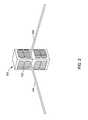
- FIG. 2is a schematic drawing of a satellite according to one aspect of the disclosed technology.
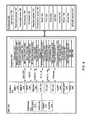
- FIG. 3is a block diagram of satellite architecture according to one aspect of the disclosed technology.
- FIG. 4is a block diagram of the on-board computer according to one aspect of the disclosed technology.
- FIG. 1illustrates an exemplary terrestrial and orbital communication network 100 covering at least a portion of a planet 110 , such as the Earth.
- the network 100may include a constellation of satellites 120 each configured to collect data from a point on the planet from time to time or on a regular basis.
- the satellite 120may analyze the collected data to monitor maritime activities, including but not limited to tracking ship or oceangoing vessels, detecting illegal, unreported and unregulated fishing or pirate activities, monitoring trade transit, and detecting oil spill, among other possibilities.
- the satellite 120may be a cubesat having a small form factor.
- the size of the satellite 120may be relatively small, in general not exceeding 10 cm ⁇ 10 cm ⁇ 30 cm and 10 kg of mass.
- the satellite 120may be based on an industry standard, developed in 2001 by Stanford University and California Polytechnic Institute and described in the document “CubeSat Design Specification.” Cubesats may be launched and deployed using a common deployment system. For example, cubesats may be launched and deployed from a mechanism called a Poly-PicoSatellite Orbital Deployer (P-POD). P-PODs may be mounted to a launch vehicle and carry cubesats into orbit. P-PODs may deploy cubesats once a proper signal is received from the launch vehicle.
- P-PODPoly-PicoSatellite Orbital Deployer
- FIG. 2is a schematic drawing of a satellite according to one aspect of the disclosed technology.
- the satellite 120may include one or more solar panels 122 .
- the solar panels 122may be configured to provide energy to one or more components contained within the satellite 120 .
- the satellite 120may also include one or more antennas 124 that may extend when fully deployed.
- FIG. 3illustrates an architecture design of the satellite 120 according to one aspect of the disclosed technology.
- the satellite 120may include an on-board computer (OBC) 200 that acts as a central computer, a power distribution unit (PDU) 300 that routes and regulates power throughout the satellite 120 , and a communications system 400 configured to handle radio communications of the satellite 120 .
- the satellite 120may also include an automatic identification system (AIS) 500 .
- the OBC 200 , the PDU 300 , the communications system 400 , and the AIS 500may communicate with one another via a controller area network (CAN) bus 600 .
- CANcontroller area network
- the OBC 200may include a System on Module (SOM) board processor 210 and a USB/FTDI connector 220 .
- the PDU 300may include a microcontroller (MCU) 310 and a CAN transceiver 320 .
- the communications system 400may include a MCU 410 , radios such as a UHF/VHF radio 420 and an S-band radio 430 , and a CAN transceiver 440 .
- the AIS 500may include a MCU 510 and a CAN transceiver 520 .
- the satellite 120may also include one or more other systems, subsystems, components, devices, parts or peripherals.
- the satellite 120may include one or more sun sensors 710 , one or more cameras such as a camera 720 and an infrared camera 730 , a sensor printed circuit board (PCB) 740 , RS 232 750 , and an attitude detection/control system (ADCS) 760 directly or indirectly coupled to the OBC 200 .
- the satellite 120may include an electrical power source (EPS) 810 , a UHF antenna system 820 , a VNF antenna system 830 , and one or more batteries (BPX) 840 , all of which may be coupled to the PDU 300 via an inter-integrated circuit (I 2 C) 850 .
- Each antenna systemmay have one or more microcontrollers configured to perform a deployment of the antennas.
- Each antennamay have four antenna elements that may be deployed individually.
- the satellite 120may also include a GPS radio occultation receiver, such as a GPS radio occultation sensor (GPS-RO) receiver 910 , coupled to the communications system 400 .
- GPS-ROGPS radio occultation sensor
- the OBC 200may act as a central computer for the satellite 120 .
- FIG. 4is a block diagram of the OBC 200 according to one aspect of the disclosed technology.
- the OBC 200may include a system on chip or system on module 210 , such as a SOM board.
- the OBC 200may also include one or more hardware interfaces 230 and a backplane 260 .
- the OBC 200may run at a speed between 500 MHz and 1 GHz. Detailed discussions of some components of the OBC 200 are provided herein.
- the SOM board 210may include a general purpose central processing unit (CPU) powered by a processor 212 .
- CPUcentral processing unit
- the SOM board 210may include one or more physical storage mediums, including but not limited to one or more of the following: a NOR flash 214 , a NAND flash 215 and a SDRAM 216 .
- the NOR flash 214may have a size up to 128 MB, and may act as a boot memory.
- the NAND flash 215may also act as a boot memory.
- the NAND flash 215may be of various sizes, including, but not limited to, 128 MB, 256 MB, 512 MB, and 1024 MB.
- the SDRAM 216may be a DDR2 SDRAM memory bank.
- the SDRAM 216may be of various sizes such as 128 MB or 256 MB.
- the SOM board 210may include general purpose connectors, such as pitch stacking connectors, for custom expansions. Further, the SOM board 210 may include one or more of the following: a power supply unit, a non-volatile memory which may provide additional storage area for user-specific usage, a computer clock, and a touch screen controller
- the OBC 200may be implemented with one or more hardware interfaces 230 to interface with one or more payloads, systems, subsystems, apparatus, devices, components, parts, or peripherals, which may be collectively referred to as peripherals 250 .
- the interfaces 230 and the peripherals 250may be arranged in a manner surrounding the SOM board 210 .
- Example interfaces implemented by the OBC 200may include, but not limited to, one or more multimedia card (MMC) interfaces 232 and 234 , a general-purpose input/output (GPIO) 236 for interface with a camera, an Ethernet interface 238 for debugging, a controller area network (CAN) interface 239 for a Cubesat Space Protocol (CSP) bus, an I 2 C 240 for interface with one or more low-level sensors, a serial peripheral interface (SPI) 242 for a high-speed radio, one or more universal asynchronous receivers/transmitters (UART) 244 for interface with one or more peripherals, one or more FTDI UART 245 , and a video interface 246 for receiving or transmitting high band width data. Details with regard to each interface are provided herein.
- MMCmultimedia card
- GPIOgeneral-purpose input/output
- CANcontroller area network
- CSPCubesat Space Protocol
- I 2 C 240for interface with one or more low-level sensors
- SPIserial
- An MMC interface 232 or 234may be implemented by one or more MMC host controllers integrated in the processor 212 of the OBC 200 .
- the MMC interfacemay be coupled to a secure digital (SD) card, e.g., a multimedia card, to store system memory.
- SDsecure digital
- the MMC interfacemay interface to a camera, such as a high-definition personal camera, that captures still photos or videos. Such a camera may work automatically with minimum intervention, or remotely controlled.
- the OBC 200may include two MMC interfaces 232 and 234 .
- the GPIO 236may include a generic pin on an integrated circuit, and its behavior may be controlled by a user at run time.
- the GPIO interface 236may be configured to be coupled to a camera, such as a high-definition personal camera, to capture still photos or videos. Such a camera may work automatically with minimum intervention, or remotely controlled.
- the Ethernet interface 238may be implemented by an Ethernet physical layer that provides interface signals.
- the Ethernet interface 238may be configured to serve for debugging purposes.
- the CAN interface 239may be implemented by a CAN controller integrated in the processor 212 .
- the CAN controllermay be a high end CAN controller (HECC).
- the HECCmay be connected to an on-board physical layer. Signal lines such as CANH and CANL may be routed to a connector.
- the CAN interface 239may serve as a CSP bus.
- the CAN interface 239may connect the OBC 200 with the PDU 300 , the communications system 400 , and the AIS 500 .
- the OBC 200may include one or more I 2 C 240 for interface with one or more low-level sensors.
- Such low-level sensorsmay include, but not limited to, a light sensor 186 , a thermopile sensor 187 for temperature measurement, a thermopile array 188 for temperature measurement, an accelerator 189 , a gyroscope such as a digital output MEMS gyroscope 190 , a magnetic sensor 191 , and a temperature sensor 192 .
- the OBC 200may include two I 2 C.
- the OBC 200may include an SPI 242 for interface with a radio 193 such as a high-speed radio.
- the SPI 242may include an optional low-voltage differential signaling (LVDS) level shifting.
- the OBC 200may include an SPI channel, and may have a port that provides 3 chip selects such as MCSPI 1 _CS 0 , MCSPI 1 _CS 1 , and MCSPI 1 _CS 2 .
- the OBC 200may include one or more UARTs 244 for communication with one or more systems.
- a UART 244may be an individual or part of an integrated circuit used for serial communications over a computer or peripheral device serial port. The UART 244 may take bytes of data and transmit the individual bits in a sequential fashion. The UART 244 may be used in conjunction with communication standards such as RS- 232 .
- the OBC 200may be connected to one or more systems over the UART 244 in different ways. UART ports may be routed to connectors of the OBC 200 .
- the OBC 200may include four UARTs.
- the OBC 200may include one or more direct MCU UART channels. Such channels may serve one or more of the following functions: debug port, GPS-RO sensor UART, and ADCS UART.
- the OBC 200may include one or more FTDI UART 245 channels.
- four extra UART portsmay be created through a MCU's USB 1 port using a USB-4xUART chip.
- the whole FTDI circuitmay be switched on/off through a GPIO pin.
- One or more FTDI UART channelsmay serve one or more of the following functions: UART on the backplane for infrared camera (IR Camera) 730 , debug port for the PDU 300 , debug port for the communications system 400 , extra connector, and generic UART.
- IR Camerainfrared camera
- the OBC 200may include a video interface 246 for high band width data.
- the video interface 246may be a parallel video interface having a port configured to interface with an infrared camera 730
- the OBC 200may not directly interface with the UHF/VHF radio 420 and the S-band radio 430 .
- the backplane 260may serve as a backbone for connecting one or more printed circuit boards or peripherals 250 to the OBC 200 .
- the backplane 260may include one or more electrical connectors and parallel signal traces that connect one or more printed circuit boards or peripherals 250 to the OBC 200 .
- Each pin of each connectormay be linked to the same relative pin of all the other connectors to form a common computer bus.
- the OBC 200may have a top side with one or more of the following connectors: USB micro connector 261 , backplane connector 262 , and SOM board connectors 263 , Camera MMC connector 264 , MCU FTDI UART 3 265 , MCU JTAG 266 , Ethernet breakout 267 , IR Camera breakout 268 , USB host 269 , Camera GPIO connector 270 , Debug/bootstrap UART 3 breakout/FTDI UART breakout 271 , FTDI UART breakout 272 , I 2 C breakout 273 , serial peripheral interface (SPI) connector 274 , CAN breakout 275 , USB power jumper 276 , power breakout 277 , CAN termination jumper 278 , UART breakout 279 , CPU UART 280 , CPU ICSP 281 , and LED power jumper 282 .
- USB micro connector 261backplane connector 262
- SOM board connectors 263Camera MMC connector 264
- the USB micro connector 261may be configured to connect to an FTDI USB to 4x serial port converter.
- the USB micro connector 261may be connected to one or more ports with the following connections: Debug UART, GPS-RO sensor UART, ADCS UART, and infrared camera UART.
- the Camera MMC connector 264may have one or more of the following pins: command (e.g., MMC_CMD), Serial Clock (e.g., MMC_SCK), Data (e.g., MMC_DAT 0 , MMC_DAT 1 , MMC_DAT 2 and MMC_DAT 3 ), ground (e.g., GND), and power supply (e.g., 3.3V).
- commande.g., MMC_CMD
- Serial Clocke.g., MMC_SCK
- Datae.g., MMC_DAT 0 , MMC_DAT 1 , MMC_DAT 2 and MMC_DAT 3
- grounde.g., GND
- power supplye.g., 3.3V
- the MCU FTDI UART 3 265may have one or more pins associated with one or more of the following functions: transmit data (e.g., MCU-FTDI-TXD 1 ), receive data (e.g., MCU-FTDI-RXD 1 ), and ground (e.g., GND).
- transmit datae.g., MCU-FTDI-TXD 1
- receive datae.g., MCU-FTDI-RXD 1
- grounde.g., GND
- the MCU JTAG 266may have one or more pins associated with one or more of the following functions: test clock (e.g., TCK), test data in (e.g., TDI), test data out (e.g., TDO), test mode select (e.g., TMS), rest (e.g., RST), power supply (e.g., 3.3V), and ground (e.g., GND).
- test clocke.g., TCK
- test data ine.g., TDI
- test data oute.g., TDO
- test mode selecte.g., TMS
- reste.g., RST
- power supplye.g., 3.3V
- grounde.g., GND
- the Ethernet breakout 267may have one or more pins associated with one or more of the following functions: receive data (e.g., RX+ and RX ⁇ ), transmit data (e.g., TX+ and TX ⁇ ), light emitting diode (e.g., LED 1 and LED 2 ), and ground (e.g., GND).
- receive datae.g., RX+ and RX ⁇
- transmit datae.g., TX+ and TX ⁇
- light emitting diodee.g., LED 1 and LED 2
- grounde.g., GND
- the IR Camera breakout 268may have one or more pins associated with one or more of the following functions: horizontal sync (e.g., HSYNC), vertical sync (e.g., VSYNC), processor clock (e.g., PCLK), data (e.g., DATA 0 , DATA 1 , DATA 2 , DATA 3 , DATA 4 , DATA 5 , DATA 6 and DATA 7 ), and ground (e.g., GND).
- horizontal synce.g., HSYNC
- vertical synce.g., VSYNC
- processor clocke.g., PCLK
- datae.g., DATA 0 , DATA 1 , DATA 2 , DATA 3 , DATA 4 , DATA 5 , DATA 6 and DATA 7
- grounde.g., GND
- the USB host 269may have one or more pins associated with one or more of the following functions: power supply (e.g., 5V), ground (e.g., GND), and USB data (e.g., USB 2 ⁇ and USB2+).
- power supplye.g., 5V
- grounde.g., GND
- USB datae.g., USB 2 ⁇ and USB2+
- the Camera GPIO connector 270may have one or more pins associated with one or more of the following functions: power supply (e.g., 3.3V coming from Camera), ground (e.g., GND), and camera data
- the Debug/bootstrap UART 3 breakout/FTDI UART breakout 271may have one or more pins associated with one or more of the following functions: receive data (e.g., MCU-FTDI-TXD 2 ), transmit data (e.g., MCU-FTDI-RXD 2 ), and ground (e.g., GND).
- receive datae.g., MCU-FTDI-TXD 2
- transmit datae.g., MCU-FTDI-RXD 2
- grounde.g., GND
- the FTDI UART breakout 272may have one or more pins associated with one or more of the following functions: receive data (e.g., MCU-FTDI-TXD 3 ), transmit data (e.g., MCU-FTDI-RXD 3 ), and ground (GND).
- receive datae.g., MCU-FTDI-TXD 3
- transmit datae.g., MCU-FTDI-RXD 3
- ground (GND)ground
- the I 2 C breakout 273may have one or more pins associated with one or more of the following functions: serial clock line (e.g., SCL 0 and SCL 1 ), serial data line (e.g., SDA 0 and SDA 1 ), and ground (e.g., GND).
- serial clock linee.g., SCL 0 and SCL 1
- serial data linee.g., SDA 0 and SDA 1
- grounde.g., GND
- the SPI connector 274may have one or more pins associated with one or more of the following functions: serial clock (e.g., SPI SCK LVDS+, SPI SCK LVDS ⁇ and SPI SCK), ground (e.g., GND), master OUT slave IN (e.g., SPI MOSI, SPI MOSI LVDS+ and SPI MOSI LVDS ⁇ ), and master IN slave OUT (e.g., SPI MISO, SPI MISO LVDS+ and SPI MISO LVDS ⁇ ), chip select (e.g., SPI CS 1 and SPI CS 2 ), and high speed general-purpose input/output (e.g., HS GPIO 0 and HS GPIO 1 ).
- serial clocke.g., SPI SCK LVDS+, SPI SCK LVDS ⁇ and SPI SCK
- grounde.g., GND
- master OUT slave INe.g., SPI MOSI, SPI MO
- the CAN breakout 275may have one or more pins associated with one or more of the following functions: high voltage signal (e.g., CANH) and low voltage signal (e.g., CANL).
- high voltage signale.g., CANH
- low voltage signale.g., CANL
- the USB power jumper 276may have one or more pins associated with the following function: power supply (e.g., 5V USB and 5V).
- power supplye.g., 5V USB and 5V.
- the power breakout 277may have one or more pins associated with one or more of the following functions: power supply (e.g., 5V and 3.3V), battery voltage (e.g., VBAT), and ground (e.g., GND).
- power supplye.g., 5V and 3.3V
- battery voltagee.g., VBAT
- grounde.g., GND
- the CAN termination jumper 278may have one or more pins associated with one or more of the following functions: high voltage signal (e.g., CANH) and low voltage signal (e.g., CANL).
- high voltage signale.g., CANH
- low voltage signale.g., CANL
- the UART breakout 279may have one or more pins associated with one or more of the following functions: receive data (e.g., ADCS_RX and GPS-RO sensor_RX) and transmit data (e.g., ADCS_TX and GPS-RO sensor_TX).
- receive datae.g., ADCS_RX and GPS-RO sensor_RX
- transmit datae.g., ADCS_TX and GPS-RO sensor_TX
- the CPU UART 280may have one or more pins associated with one or more of the following functions: receive data (e.g., RX) and transmit data (e.g., TX).
- receive datae.g., RX
- transmit datae.g., TX
- the LED power jumper 282may have one or more pins associated with the following function: ground (e.g., GND and LED_GND).
- the OBC 200may have a bottom side with one or more of secure digital (SD) connectors 283 .
- SD 1 283may connect to MMC 1 on the SOM board 210 directly.
- SD 2 284may connect to MMC 2 on the SOM board 210 through a multiplexer, e.g., camera SD mux.
- the OBC 200may have many advantages.
- the OBC 200may have a small form factor with inexpensive connectors.
- the OBC 200may offer high flexibility, great performances, low power consumption and a rich interface set.
- the OBC 200may work in extreme environmental conditions.
- the OBC 200may work in an extended temperature range from ⁇ 40° C. to +85° C.
- the disclosed technologyis not to be limited to the disclosed implementations, but on the contrary, is intended to cover various modifications and equivalent arrangements included within the scope of the appended claims.
- specific termsare employed herein, they are used in a generic and descriptive sense only and not for purposes of limitation.
- the disclosed technologymay be implemented in an aerospace device or system, including but not limited to, satellite communication systems of all sizes, and aircrafts including airplanes, jets, and air balloon, among other possibilities.
- the disclosed technologymay serve multiple purposes, including monitoring maritime activities, monitoring trade transit, general aviation, commercial and private purposes including transport and cargo services, and military purposes, among other possibilities.
- These computer program instructionsmay also be stored in a computer-readable memory that can direct a computer or other programmable data processing apparatus to function in a particular manner, such that the instructions stored in the computer-readable memory produce an article of manufacture including instruction means that implement one or more functions specified in the flow diagram block or blocks.
- Implementations of the disclosed technologymay provide for a computer program product, comprising a computer-usable medium having a computer-readable program code or program instructions embodied therein, said computer-readable program code adapted to be executed to implement one or more functions specified in the flow diagram block or blocks.
- the computer program instructionsmay also be loaded onto a computer or other programmable data processing apparatus to cause a series of operational elements or steps to be performed on the computer or other programmable apparatus to produce a computer-implemented process such that the instructions that execute on the computer or other programmable apparatus provide elements or steps for implementing the functions specified in the flow diagram block or blocks.
- blocks of the block diagrams and flow diagramssupport combinations of means for performing the specified functions, combinations of elements or steps for performing the specified functions and program instruction means for performing the specified functions. It will also be understood that each block of the block diagrams and flow diagrams, and combinations of blocks in the block diagrams and flow diagrams, can be implemented by special-purpose, hardware-based computer systems that perform the specified functions, elements or steps, or combinations of special-purpose hardware and computer instructions.
Landscapes
- Engineering & Computer Science (AREA)
- Theoretical Computer Science (AREA)
- Physics & Mathematics (AREA)
- General Engineering & Computer Science (AREA)
- General Physics & Mathematics (AREA)
- Signal Processing (AREA)
- Mathematical Physics (AREA)
- Computer Hardware Design (AREA)
- Astronomy & Astrophysics (AREA)
- Aviation & Aerospace Engineering (AREA)
- Computer Networks & Wireless Communication (AREA)
- Arrangements For Transmission Of Measured Signals (AREA)
- Multimedia (AREA)
- Multi Processors (AREA)
Abstract
Description
Claims (16)
Priority Applications (2)
| Application Number | Priority Date | Filing Date | Title |
|---|---|---|---|
| US14/632,535US9830297B2 (en) | 2015-02-26 | 2015-02-26 | Processor system for control of modular autonomous system |
| PCT/US2016/014863WO2016190915A2 (en) | 2015-02-26 | 2016-01-26 | Processor system for control of modular autonomous system |
Applications Claiming Priority (1)
| Application Number | Priority Date | Filing Date | Title |
|---|---|---|---|
| US14/632,535US9830297B2 (en) | 2015-02-26 | 2015-02-26 | Processor system for control of modular autonomous system |
Publications (2)
| Publication Number | Publication Date |
|---|---|
| US20160253284A1 US20160253284A1 (en) | 2016-09-01 |
| US9830297B2true US9830297B2 (en) | 2017-11-28 |
Family
ID=56798924
Family Applications (1)
| Application Number | Title | Priority Date | Filing Date |
|---|---|---|---|
| US14/632,535Active2035-11-23US9830297B2 (en) | 2015-02-26 | 2015-02-26 | Processor system for control of modular autonomous system |
Country Status (2)
| Country | Link |
|---|---|
| US (1) | US9830297B2 (en) |
| WO (1) | WO2016190915A2 (en) |
Cited By (8)
| Publication number | Priority date | Publication date | Assignee | Title |
|---|---|---|---|---|
| US20220237136A1 (en)* | 2021-01-26 | 2022-07-28 | Genesys Logic, Inc. | Switching method of usb switch element for in-vehicle host system |
| US20220261366A1 (en)* | 2021-02-16 | 2022-08-18 | Red Hat, Inc. | Direct memory control operations on memory data structures |
| TWI794996B (en)* | 2021-06-28 | 2023-03-01 | 慧榮科技股份有限公司 | Apparatus and system for debugging solid state disk devices |
| US20230176985A1 (en)* | 2021-12-06 | 2023-06-08 | Himax Technologies Limited | Serial peripheral interface integrated circuit and operation method thereof |
| US11841398B2 (en) | 2021-06-28 | 2023-12-12 | Silicon Motion, Inc. | Method and apparatus and non-transitory computer-readable storage medium for debugging solid-state disk (SSD) device |
| US11933847B2 (en) | 2021-06-28 | 2024-03-19 | Silicon Motion, Inc. | Apparatus and system for debugging solid-state disk (SSD) device |
| US12105993B2 (en) | 2021-06-28 | 2024-10-01 | Silicon Motion, Inc. | Method and apparatus and non-transitory computer-readable storage medium for debugging solid-state disk (SSD) device |
| US20250021513A1 (en)* | 2023-07-12 | 2025-01-16 | Silergy Semiconductor Technology (Hangzhou) Ltd | Synchronization signal transmission method and serial communication system |
Families Citing this family (14)
| Publication number | Priority date | Publication date | Assignee | Title |
|---|---|---|---|---|
| US9678136B2 (en)* | 2014-10-15 | 2017-06-13 | Spire Global, Inc. | Back-plane connector for cubesat |
| US11198524B2 (en) | 2015-03-02 | 2021-12-14 | Technion Research & Development Foundation Limited | Terrestrially observable displays from space |
| US9996450B2 (en) | 2016-05-03 | 2018-06-12 | The Boeing Company | Transferring application software between virtual machines |
| US10810108B2 (en)* | 2016-05-03 | 2020-10-20 | The Boeing Company | Testing application programs using a virtual machine |
| US10108531B2 (en) | 2016-05-03 | 2018-10-23 | The Boeing Company | Transferring application software from a physical to a virtual computer system |
| CN106647456A (en)* | 2016-10-14 | 2017-05-10 | 中国空间技术研究院 | Intelligent satellite platform system and on-orbit application expansion method |
| US10171633B2 (en)* | 2017-03-09 | 2019-01-01 | Astronics Advanced Electronic Systems Corp. | Interfaces for selecting among multiple communications protocols |
| US9973266B1 (en) | 2017-06-12 | 2018-05-15 | Ast & Science, Llc | System and method for high throughput fractionated satellites (HTFS) for direct connectivity to and from end user devices and terminals using flight formations of small or very small satellites |
| US10979133B2 (en) | 2017-06-12 | 2021-04-13 | Ast & Science, Llc | System and method for high throughput fractionated satellites (HTFS) for direct connectivity to and from end user devices and terminals using flight formations of small or very small satellites |
| CN108183741B (en)* | 2017-11-29 | 2021-07-13 | 山东航天电子技术研究所 | A universal on-board electronic system for micro-nano satellites |
| KR102839863B1 (en) | 2019-05-15 | 2025-07-28 | 에이에스티 앤 사이언스, 엘엘씨 | Mechanically deployable structure in low Earth orbit |
| BG67584B1 (en)* | 2020-10-22 | 2023-10-31 | "Ендуросат" Ад | Unifying platform for nanosatellite systems |
| US11809355B2 (en)* | 2021-02-05 | 2023-11-07 | SK Hynix Inc. | UART aggregation and JTAG selection circuitry for a multi-solid state drive environment |
| US20250070864A1 (en)* | 2023-08-24 | 2025-02-27 | Antaris Inc. | Methods, devices, and systems for on-orbit autonomous recovery of satellites |
Citations (38)
| Publication number | Priority date | Publication date | Assignee | Title |
|---|---|---|---|---|
| US4454510A (en) | 1978-12-18 | 1984-06-12 | Crow Robert P | Discrete address beacon, navigation and landing system (DABNLS) |
| US5940739A (en) | 1997-10-24 | 1999-08-17 | Conrad; Charles | Multiple access satellite communications network |
| US6023291A (en) | 1996-10-16 | 2000-02-08 | Space Systems/Loral, Inc. | Satellite camera attitude determination and image navigation by means of earth edge and landmark measurement |
| US6356966B1 (en) | 2000-09-12 | 2002-03-12 | Apw Ltd. | System and method for bridging bus segments on a backplane and coupling single board computers to a backplane |
| US20040008034A1 (en) | 2002-07-09 | 2004-01-15 | Mastoris Steven F. | Testing device and method for testing backplanes and connectors on backplanes |
| US20040226046A1 (en) | 2003-05-05 | 2004-11-11 | Shih-Hsiung Weng | Telecommunication network-based remote surveillance method and system |
| US20060282724A1 (en) | 2005-06-14 | 2006-12-14 | Microsoft Corporation | Programmatically switched hot-plug PCI slots |
| US20080086509A1 (en) | 2006-10-05 | 2008-04-10 | Daniel John Wallace | System and method for asset management |
| US20080291855A1 (en)* | 2006-11-14 | 2008-11-27 | Phase Iv Engineering, Inc. | Wireless Data Networking |
| US7503511B2 (en) | 2004-09-08 | 2009-03-17 | Space Exploration Technologies | Pintle injector tip with active cooling |
| US20090087029A1 (en) | 2007-08-22 | 2009-04-02 | American Gnc Corporation | 4D GIS based virtual reality for moving target prediction |
| US20090201379A1 (en) | 2002-04-10 | 2009-08-13 | Schultz Kevin L | Smart Camera with Modular Expansion Capability Including a Function Module that Performs Image Processing |
| US20090290534A1 (en) | 2006-10-03 | 2009-11-26 | Viasat, Inc. | Upfront delayed concatenation in satellite communication system |
| US20090307592A1 (en)* | 2008-02-18 | 2009-12-10 | Massachusetts Institute Of Technology | Tangible Social Network |
| US7733635B2 (en) | 2002-10-22 | 2010-06-08 | Sullivan Jason A | Systems and methods for providing a robust computer processing unit |
| US7860582B2 (en) | 2004-06-23 | 2010-12-28 | National Instruments Corporation | Compact modular embedded device |
| US20110116441A1 (en) | 2008-05-16 | 2011-05-19 | O3B Limited | Systems and methods for satellite communication |
| US20110170797A1 (en) | 2006-05-01 | 2011-07-14 | University Corporation For Atmospheric Research | Optical device for correcting geostationary satellite imagery for earth curvature effects |
| US8117587B1 (en)* | 2008-06-03 | 2012-02-14 | Richard Paul Testardi | Microcontroller-resident software development environment supporting application-level asynchronous event handling, interactive debugging and pin variables for embedded systems |
| US8306385B2 (en) | 2005-04-15 | 2012-11-06 | Sony Corporation | Recording apparatus and mount control method |
| US8378913B2 (en) | 2009-12-15 | 2013-02-19 | Arcadyan Technology Corporation | Dual-band antenna unit |
| US20130051661A1 (en) | 2011-08-26 | 2013-02-28 | Skybox Imaging, Inc. | Using Human Intelligence Tasks for Precise Image Analysis |
| US8482610B2 (en) | 2010-12-15 | 2013-07-09 | Skybox Imaging, Inc. | Integrated antenna system for imaging microsatellites |
| US8487996B2 (en) | 2011-04-25 | 2013-07-16 | Skybox Imaging, Inc. | Systems and methods for overhead imaging and video |
| US20130235234A1 (en) | 2012-03-12 | 2013-09-12 | Megan Lyn Cucci | Digital camera having multiple image capture systems |
| US20130271628A1 (en) | 2012-04-17 | 2013-10-17 | Skybox Imaging, Inc. | Sensor dark pixel offset estimation |
| US20130298083A1 (en) | 2012-05-04 | 2013-11-07 | Skybox Imaging, Inc. | Overhead image viewing systems and methods |
| US20140027576A1 (en) | 2012-07-25 | 2014-01-30 | Planet Labs Inc. | Earth Observation Constellation Methodology & Applications |
| US20140039729A1 (en)* | 2012-08-06 | 2014-02-06 | Jordi Puig-Suari | Cubesat system, method and apparatus |
| US20140039963A1 (en) | 2012-08-03 | 2014-02-06 | Skybox Imaging, Inc. | Satellite scheduling system |
| US20140059166A1 (en) | 2012-08-21 | 2014-02-27 | Skybox Imaging, Inc. | Multi-resolution pyramid for georeferenced video |
| US20140118256A1 (en) | 2012-10-29 | 2014-05-01 | Lenovo (Singapore) Pte, Ltd | Display directional sensing |
| US20140222472A1 (en) | 2013-02-01 | 2014-08-07 | Peter Platzer | System and method for widespread low cost orbital satellite access |
| WO2014121197A2 (en) | 2013-02-01 | 2014-08-07 | NanoSatisfi Inc. | System and method for widespread low cost orbital satellite access |
| US8948080B2 (en) | 2007-07-17 | 2015-02-03 | Overhorizon (Cyprus) Plc | Methods comprising satellites having a regenerative payload, onboard computer, payload interface and interference elimination system |
| US20150097084A1 (en)* | 2013-10-04 | 2015-04-09 | Busek Co., Inc. | Spacecraft system for debris disposal and other operations and methods pertaining to the same |
| US20150146019A1 (en) | 2012-09-03 | 2015-05-28 | Canon Kabushiki Kaisha | Communication control apparatus and method for controlling the same |
| US20150199556A1 (en) | 2014-01-13 | 2015-07-16 | Honeywell International Inc. | Method of using image warping for geo-registration feature matching in vision-aided positioning |
- 2015
- 2015-02-26USUS14/632,535patent/US9830297B2/enactiveActive
- 2016
- 2016-01-26WOPCT/US2016/014863patent/WO2016190915A2/ennot_activeCeased
Patent Citations (41)
| Publication number | Priority date | Publication date | Assignee | Title |
|---|---|---|---|---|
| US4454510A (en) | 1978-12-18 | 1984-06-12 | Crow Robert P | Discrete address beacon, navigation and landing system (DABNLS) |
| US6023291A (en) | 1996-10-16 | 2000-02-08 | Space Systems/Loral, Inc. | Satellite camera attitude determination and image navigation by means of earth edge and landmark measurement |
| US5940739A (en) | 1997-10-24 | 1999-08-17 | Conrad; Charles | Multiple access satellite communications network |
| US6356966B1 (en) | 2000-09-12 | 2002-03-12 | Apw Ltd. | System and method for bridging bus segments on a backplane and coupling single board computers to a backplane |
| US20090201379A1 (en) | 2002-04-10 | 2009-08-13 | Schultz Kevin L | Smart Camera with Modular Expansion Capability Including a Function Module that Performs Image Processing |
| US20040008034A1 (en) | 2002-07-09 | 2004-01-15 | Mastoris Steven F. | Testing device and method for testing backplanes and connectors on backplanes |
| US7733635B2 (en) | 2002-10-22 | 2010-06-08 | Sullivan Jason A | Systems and methods for providing a robust computer processing unit |
| US20040226046A1 (en) | 2003-05-05 | 2004-11-11 | Shih-Hsiung Weng | Telecommunication network-based remote surveillance method and system |
| US7860582B2 (en) | 2004-06-23 | 2010-12-28 | National Instruments Corporation | Compact modular embedded device |
| US7503511B2 (en) | 2004-09-08 | 2009-03-17 | Space Exploration Technologies | Pintle injector tip with active cooling |
| US8306385B2 (en) | 2005-04-15 | 2012-11-06 | Sony Corporation | Recording apparatus and mount control method |
| US20060282724A1 (en) | 2005-06-14 | 2006-12-14 | Microsoft Corporation | Programmatically switched hot-plug PCI slots |
| US20110170797A1 (en) | 2006-05-01 | 2011-07-14 | University Corporation For Atmospheric Research | Optical device for correcting geostationary satellite imagery for earth curvature effects |
| US20090290534A1 (en) | 2006-10-03 | 2009-11-26 | Viasat, Inc. | Upfront delayed concatenation in satellite communication system |
| US20080086509A1 (en) | 2006-10-05 | 2008-04-10 | Daniel John Wallace | System and method for asset management |
| US20080291855A1 (en)* | 2006-11-14 | 2008-11-27 | Phase Iv Engineering, Inc. | Wireless Data Networking |
| US8948080B2 (en) | 2007-07-17 | 2015-02-03 | Overhorizon (Cyprus) Plc | Methods comprising satellites having a regenerative payload, onboard computer, payload interface and interference elimination system |
| US20090087029A1 (en) | 2007-08-22 | 2009-04-02 | American Gnc Corporation | 4D GIS based virtual reality for moving target prediction |
| US20090307592A1 (en)* | 2008-02-18 | 2009-12-10 | Massachusetts Institute Of Technology | Tangible Social Network |
| US20110116441A1 (en) | 2008-05-16 | 2011-05-19 | O3B Limited | Systems and methods for satellite communication |
| US8117587B1 (en)* | 2008-06-03 | 2012-02-14 | Richard Paul Testardi | Microcontroller-resident software development environment supporting application-level asynchronous event handling, interactive debugging and pin variables for embedded systems |
| US8378913B2 (en) | 2009-12-15 | 2013-02-19 | Arcadyan Technology Corporation | Dual-band antenna unit |
| US8531524B2 (en) | 2010-12-15 | 2013-09-10 | Skybox Imaging, Inc. | Integrated antenna system for imaging microsatellites |
| US20140015970A1 (en) | 2010-12-15 | 2014-01-16 | Skybox Imaging, Inc. | Integrated antenna system for imaging microsatellites |
| US8482610B2 (en) | 2010-12-15 | 2013-07-09 | Skybox Imaging, Inc. | Integrated antenna system for imaging microsatellites |
| US8487996B2 (en) | 2011-04-25 | 2013-07-16 | Skybox Imaging, Inc. | Systems and methods for overhead imaging and video |
| US20130051661A1 (en) | 2011-08-26 | 2013-02-28 | Skybox Imaging, Inc. | Using Human Intelligence Tasks for Precise Image Analysis |
| US20130235234A1 (en) | 2012-03-12 | 2013-09-12 | Megan Lyn Cucci | Digital camera having multiple image capture systems |
| US20130271628A1 (en) | 2012-04-17 | 2013-10-17 | Skybox Imaging, Inc. | Sensor dark pixel offset estimation |
| US20130298083A1 (en) | 2012-05-04 | 2013-11-07 | Skybox Imaging, Inc. | Overhead image viewing systems and methods |
| US20140027576A1 (en) | 2012-07-25 | 2014-01-30 | Planet Labs Inc. | Earth Observation Constellation Methodology & Applications |
| US20140039963A1 (en) | 2012-08-03 | 2014-02-06 | Skybox Imaging, Inc. | Satellite scheduling system |
| US20140040282A1 (en) | 2012-08-03 | 2014-02-06 | Skybox Imaging, Inc. | Satellite scheduling system using crowd-sourced data |
| US20140039729A1 (en)* | 2012-08-06 | 2014-02-06 | Jordi Puig-Suari | Cubesat system, method and apparatus |
| US20140059166A1 (en) | 2012-08-21 | 2014-02-27 | Skybox Imaging, Inc. | Multi-resolution pyramid for georeferenced video |
| US20150146019A1 (en) | 2012-09-03 | 2015-05-28 | Canon Kabushiki Kaisha | Communication control apparatus and method for controlling the same |
| US20140118256A1 (en) | 2012-10-29 | 2014-05-01 | Lenovo (Singapore) Pte, Ltd | Display directional sensing |
| US20140222472A1 (en) | 2013-02-01 | 2014-08-07 | Peter Platzer | System and method for widespread low cost orbital satellite access |
| WO2014121197A2 (en) | 2013-02-01 | 2014-08-07 | NanoSatisfi Inc. | System and method for widespread low cost orbital satellite access |
| US20150097084A1 (en)* | 2013-10-04 | 2015-04-09 | Busek Co., Inc. | Spacecraft system for debris disposal and other operations and methods pertaining to the same |
| US20150199556A1 (en) | 2014-01-13 | 2015-07-16 | Honeywell International Inc. | Method of using image warping for geo-registration feature matching in vision-aided positioning |
Non-Patent Citations (3)
| Title |
|---|
| International Search Report and Written Opinion dated Apr. 27, 2016 issued in corresponding PCT International Application No. PCT/US2015/054906. |
| International Search Report and Written Opinion dated Nov. 18, 2016 issued in corresponding PCT International Application No. PCT/US2016/014863. |
| International Search Report dated Feb. 24, 2016, issued in corresponding Application No. PCT/US2015/054889. |
Cited By (11)
| Publication number | Priority date | Publication date | Assignee | Title |
|---|---|---|---|---|
| US20220237136A1 (en)* | 2021-01-26 | 2022-07-28 | Genesys Logic, Inc. | Switching method of usb switch element for in-vehicle host system |
| US12007926B2 (en)* | 2021-01-26 | 2024-06-11 | Genesys Logic, Inc. | Switching method of USB switch element for in-vehicle host system |
| US20220261366A1 (en)* | 2021-02-16 | 2022-08-18 | Red Hat, Inc. | Direct memory control operations on memory data structures |
| US11960420B2 (en)* | 2021-02-16 | 2024-04-16 | Red Hat, Inc. | Direct memory control operations on memory data structures |
| TWI794996B (en)* | 2021-06-28 | 2023-03-01 | 慧榮科技股份有限公司 | Apparatus and system for debugging solid state disk devices |
| US11841398B2 (en) | 2021-06-28 | 2023-12-12 | Silicon Motion, Inc. | Method and apparatus and non-transitory computer-readable storage medium for debugging solid-state disk (SSD) device |
| US11933847B2 (en) | 2021-06-28 | 2024-03-19 | Silicon Motion, Inc. | Apparatus and system for debugging solid-state disk (SSD) device |
| US12105993B2 (en) | 2021-06-28 | 2024-10-01 | Silicon Motion, Inc. | Method and apparatus and non-transitory computer-readable storage medium for debugging solid-state disk (SSD) device |
| US20230176985A1 (en)* | 2021-12-06 | 2023-06-08 | Himax Technologies Limited | Serial peripheral interface integrated circuit and operation method thereof |
| US11847077B2 (en)* | 2021-12-06 | 2023-12-19 | Himax Technologies Limited | Serial peripheral interface integrated circuit and operation method thereof |
| US20250021513A1 (en)* | 2023-07-12 | 2025-01-16 | Silergy Semiconductor Technology (Hangzhou) Ltd | Synchronization signal transmission method and serial communication system |
Also Published As
| Publication number | Publication date |
|---|---|
| WO2016190915A3 (en) | 2017-01-05 |
| US20160253284A1 (en) | 2016-09-01 |
| WO2016190915A2 (en) | 2016-12-01 |
Similar Documents
| Publication | Publication Date | Title |
|---|---|---|
| US9830297B2 (en) | Processor system for control of modular autonomous system | |
| US9919814B2 (en) | System and method for power distribution in a autonomous modular system | |
| US9829886B2 (en) | Flight control system, a circuit board assembly and a configuration method thereof | |
| CN107707861A (en) | Data wire, electronic system and the method for transmitting MIPI signals | |
| KR102051105B1 (en) | Movable test equipment for Air Combat Maneuvering Instrumentation-POD integrated testing, Method for controlling the same | |
| CN105208380B (en) | Verification platform and system | |
| CN110531788A (en) | Cruise control method, device and the electronic equipment of unmanned plane | |
| WO2016190916A1 (en) | System and method for communication with autonomous system in multiple bands | |
| CN204793444U (en) | On -vehicle USB concentrator, on -vehicle infotainment system and car | |
| Aoyanagi et al. | Design of 3U-CubeSat bus based on TRICOM experience to improve versatility and easiness of AIT | |
| US20140274210A1 (en) | Dual sim card adapter for mobile device | |
| Syafrudin et al. | Camera payload systems for the LAPAN A2 experimental microsatellite | |
| CN107161316A (en) | A kind of replaceable horn connect-disconnect structure of unmanned plane | |
| Pingree et al. | The prototype development phase of the CubeSat On-board processing Validation Experiment | |
| US20130181809A1 (en) | SpaceCube MINI | |
| CN208110346U (en) | UAV main control board | |
| Manco et al. | An FPGA Scalable Software-Defined Radio Platform for UAS Communications Research. | |
| CN217787641U (en) | Flight control system | |
| Petricca et al. | Design, fabrication and test of an embedded lightweight kinematic autopilot (ELKA) | |
| Drobczyk et al. | A low-cost nanosatellite approach: AISat-1 after 5 years in orbit | |
| US20130088827A1 (en) | Multi-Purpose Display Platform | |
| Goller | Sundance Avionics | |
| US20150089106A1 (en) | Expansion card having two switchable connectors | |
| Petrick | SpaceCube: current missions and ongoing platform advancements | |
| CN210351170U (en) | Relay device, image transmission device, data transmission system, airborne terminal and ground terminal |
Legal Events
| Date | Code | Title | Description |
|---|---|---|---|
| AS | Assignment | Owner name:SPIRE GLOBAL, INC., CALIFORNIA Free format text:CHANGE OF NAME;ASSIGNOR:NANOSATISFI, INC.;REEL/FRAME:035727/0911 Effective date:20150205 | |
| AS | Assignment | Owner name:NANOSATISFI, INC., CALIFORNIA Free format text:ASSIGNMENT OF ASSIGNORS INTEREST;ASSIGNORS:CAPPAERT, JEROEN;TRUTNA, JESSE;SHRAKE, NICHOLAS;SIGNING DATES FROM 20150415 TO 20150430;REEL/FRAME:035689/0158 | |
| STCF | Information on status: patent grant | Free format text:PATENTED CASE | |
| AS | Assignment | Owner name:FP CREDIT PARTNERS, L.P., AS AGENT, CALIFORNIA Free format text:INTELLECTUAL PROPERTY SECURITY AGREEMENT;ASSIGNOR:SPIRE GLOBAL, INC.;REEL/FRAME:056353/0901 Effective date:20210517 | |
| MAFP | Maintenance fee payment | Free format text:PAYMENT OF MAINTENANCE FEE, 4TH YR, SMALL ENTITY (ORIGINAL EVENT CODE: M2551); ENTITY STATUS OF PATENT OWNER: SMALL ENTITY Year of fee payment:4 | |
| AS | Assignment | Owner name:SPIRE GLOBAL SUBSIDIARY, INC., CALIFORNIA Free format text:CHANGE OF NAME;ASSIGNOR:SPIRE GLOBAL, INC.;REEL/FRAME:057468/0155 Effective date:20210816 | |
| AS | Assignment | Owner name:BLUE TORCH FINANCE LLC, NEW YORK Free format text:PATENT SECURITY AGREEMENT;ASSIGNORS:EXACTEARTH LTD.;SPIRE GLOBAL SUBSIDIARY, INC.;REEL/FRAME:060363/0171 Effective date:20220613 | |
| AS | Assignment | Owner name:AUSTIN SATELLITE DESIGN, LLC, CALIFORNIA Free format text:RELEASE BY SECURED PARTY;ASSIGNOR:FP CREDIT PARTNERS, L.P., AS ADMINISTRATIVE AGENT AND COLLATERAL AGENT;REEL/FRAME:060198/0638 Effective date:20220613 Owner name:SPIRE GLOBAL, INC., CALIFORNIA Free format text:RELEASE BY SECURED PARTY;ASSIGNOR:FP CREDIT PARTNERS, L.P., AS ADMINISTRATIVE AGENT AND COLLATERAL AGENT;REEL/FRAME:060198/0638 Effective date:20220613 | |
| AS | Assignment | Owner name:EXACTEARTH LTD., VIRGINIA Free format text:RELEASE BY SECURED PARTY;ASSIGNOR:BLUE TORCH FINANCE LLC, AS ADMINISTRATIVE AGENT;REEL/FRAME:070950/0659 Effective date:20250425 Owner name:SPIRE GLOBAL SUBSIDIARY, INC., VIRGINIA Free format text:RELEASE BY SECURED PARTY;ASSIGNOR:BLUE TORCH FINANCE LLC, AS ADMINISTRATIVE AGENT;REEL/FRAME:070950/0659 Effective date:20250425 | |
| MAFP | Maintenance fee payment | Free format text:PAYMENT OF MAINTENANCE FEE, 8TH YR, SMALL ENTITY (ORIGINAL EVENT CODE: M2552); ENTITY STATUS OF PATENT OWNER: SMALL ENTITY Year of fee payment:8 |