US9827901B1 - System and method for dynamically projecting information from a motor vehicle - Google Patents
System and method for dynamically projecting information from a motor vehicleDownload PDFInfo
- Publication number
- US9827901B1 US9827901B1US15/165,738US201615165738AUS9827901B1US 9827901 B1US9827901 B1US 9827901B1US 201615165738 AUS201615165738 AUS 201615165738AUS 9827901 B1US9827901 B1US 9827901B1
- Authority
- US
- United States
- Prior art keywords
- motor vehicle
- status
- projection profile
- indicative
- sensor
- Prior art date
- Legal status (The legal status is an assumption and is not a legal conclusion. Google has not performed a legal analysis and makes no representation as to the accuracy of the status listed.)
- Active
Links
Images


Classifications
- B—PERFORMING OPERATIONS; TRANSPORTING
- B60—VEHICLES IN GENERAL
- B60Q—ARRANGEMENT OF SIGNALLING OR LIGHTING DEVICES, THE MOUNTING OR SUPPORTING THEREOF OR CIRCUITS THEREFOR, FOR VEHICLES IN GENERAL
- B60Q1/00—Arrangement of optical signalling or lighting devices, the mounting or supporting thereof or circuits therefor
- B60Q1/26—Arrangement of optical signalling or lighting devices, the mounting or supporting thereof or circuits therefor the devices being primarily intended to indicate the vehicle, or parts thereof, or to give signals, to other traffic
- B60Q1/34—Arrangement of optical signalling or lighting devices, the mounting or supporting thereof or circuits therefor the devices being primarily intended to indicate the vehicle, or parts thereof, or to give signals, to other traffic for indicating change of drive direction
- B—PERFORMING OPERATIONS; TRANSPORTING
- B60—VEHICLES IN GENERAL
- B60Q—ARRANGEMENT OF SIGNALLING OR LIGHTING DEVICES, THE MOUNTING OR SUPPORTING THEREOF OR CIRCUITS THEREFOR, FOR VEHICLES IN GENERAL
- B60Q1/00—Arrangement of optical signalling or lighting devices, the mounting or supporting thereof or circuits therefor
- B60Q1/26—Arrangement of optical signalling or lighting devices, the mounting or supporting thereof or circuits therefor the devices being primarily intended to indicate the vehicle, or parts thereof, or to give signals, to other traffic
- B60Q1/2661—Arrangement of optical signalling or lighting devices, the mounting or supporting thereof or circuits therefor the devices being primarily intended to indicate the vehicle, or parts thereof, or to give signals, to other traffic mounted on parts having other functions
- B60Q1/2665—Arrangement of optical signalling or lighting devices, the mounting or supporting thereof or circuits therefor the devices being primarily intended to indicate the vehicle, or parts thereof, or to give signals, to other traffic mounted on parts having other functions on rear-view mirrors
- B—PERFORMING OPERATIONS; TRANSPORTING
- B60—VEHICLES IN GENERAL
- B60Q—ARRANGEMENT OF SIGNALLING OR LIGHTING DEVICES, THE MOUNTING OR SUPPORTING THEREOF OR CIRCUITS THEREFOR, FOR VEHICLES IN GENERAL
- B60Q1/00—Arrangement of optical signalling or lighting devices, the mounting or supporting thereof or circuits therefor
- B60Q1/26—Arrangement of optical signalling or lighting devices, the mounting or supporting thereof or circuits therefor the devices being primarily intended to indicate the vehicle, or parts thereof, or to give signals, to other traffic
- B60Q1/34—Arrangement of optical signalling or lighting devices, the mounting or supporting thereof or circuits therefor the devices being primarily intended to indicate the vehicle, or parts thereof, or to give signals, to other traffic for indicating change of drive direction
- B60Q1/38—Arrangement of optical signalling or lighting devices, the mounting or supporting thereof or circuits therefor the devices being primarily intended to indicate the vehicle, or parts thereof, or to give signals, to other traffic for indicating change of drive direction using immovably-mounted light sources, e.g. fixed flashing lamps
- B60Q1/381—Arrangement of optical signalling or lighting devices, the mounting or supporting thereof or circuits therefor the devices being primarily intended to indicate the vehicle, or parts thereof, or to give signals, to other traffic for indicating change of drive direction using immovably-mounted light sources, e.g. fixed flashing lamps with several light sources activated in sequence, e.g. to create a sweep effect
- G—PHYSICS
- G03—PHOTOGRAPHY; CINEMATOGRAPHY; ANALOGOUS TECHNIQUES USING WAVES OTHER THAN OPTICAL WAVES; ELECTROGRAPHY; HOLOGRAPHY
- G03B—APPARATUS OR ARRANGEMENTS FOR TAKING PHOTOGRAPHS OR FOR PROJECTING OR VIEWING THEM; APPARATUS OR ARRANGEMENTS EMPLOYING ANALOGOUS TECHNIQUES USING WAVES OTHER THAN OPTICAL WAVES; ACCESSORIES THEREFOR
- G03B21/00—Projectors or projection-type viewers; Accessories therefor
- G03B21/14—Details
- G03B21/145—Housing details, e.g. position adjustments thereof
- G—PHYSICS
- G03—PHOTOGRAPHY; CINEMATOGRAPHY; ANALOGOUS TECHNIQUES USING WAVES OTHER THAN OPTICAL WAVES; ELECTROGRAPHY; HOLOGRAPHY
- G03B—APPARATUS OR ARRANGEMENTS FOR TAKING PHOTOGRAPHS OR FOR PROJECTING OR VIEWING THEM; APPARATUS OR ARRANGEMENTS EMPLOYING ANALOGOUS TECHNIQUES USING WAVES OTHER THAN OPTICAL WAVES; ACCESSORIES THEREFOR
- G03B21/00—Projectors or projection-type viewers; Accessories therefor
- G03B21/14—Details
- G03B21/20—Lamp housings
- G03B21/2053—Intensity control of illuminating light
- G—PHYSICS
- G03—PHOTOGRAPHY; CINEMATOGRAPHY; ANALOGOUS TECHNIQUES USING WAVES OTHER THAN OPTICAL WAVES; ELECTROGRAPHY; HOLOGRAPHY
- G03B—APPARATUS OR ARRANGEMENTS FOR TAKING PHOTOGRAPHS OR FOR PROJECTING OR VIEWING THEM; APPARATUS OR ARRANGEMENTS EMPLOYING ANALOGOUS TECHNIQUES USING WAVES OTHER THAN OPTICAL WAVES; ACCESSORIES THEREFOR
- G03B29/00—Combinations of cameras, projectors or photographic printing apparatus with non-photographic non-optical apparatus, e.g. clocks or weapons; Cameras having the shape of other objects
- B—PERFORMING OPERATIONS; TRANSPORTING
- B60—VEHICLES IN GENERAL
- B60Q—ARRANGEMENT OF SIGNALLING OR LIGHTING DEVICES, THE MOUNTING OR SUPPORTING THEREOF OR CIRCUITS THEREFOR, FOR VEHICLES IN GENERAL
- B60Q2400/00—Special features or arrangements of exterior signal lamps for vehicles
- B60Q2400/40—Welcome lights, i.e. specific or existing exterior lamps to assist leaving or approaching the vehicle
- B—PERFORMING OPERATIONS; TRANSPORTING
- B60—VEHICLES IN GENERAL
- B60Q—ARRANGEMENT OF SIGNALLING OR LIGHTING DEVICES, THE MOUNTING OR SUPPORTING THEREOF OR CIRCUITS THEREFOR, FOR VEHICLES IN GENERAL
- B60Q2400/00—Special features or arrangements of exterior signal lamps for vehicles
- B60Q2400/50—Projected symbol or information, e.g. onto the road or car body
Definitions
- the inventionrelates generally to a system and method for dynamically projecting information from a motor vehicle, and more particularly to a system and method for projecting a dynamic projection profile based on a data signal which is indicative of a status of the motor vehicle.
- Motor vehicleshave been designed with increasingly advanced technologies aimed at improving the safety, efficiency, and performance of the motor vehicle.
- technologiesinclude advanced driver assistance systems and human machine interface systems.
- advanced driver assistance systemsautomate, adapt, or enhance vehicle systems in order to increase vehicle safety and/or operator driving performance.
- Advanced driver assistance systemsare designed to avoid accidents by offering technologies that alert the driver to potential problems or to avoid collisions by implementing safeguards, such as autonomously controlling the vehicle.
- Operator driving performancemay be improved by using features that enhance certain systems, such as automated lighting, automated parking, adaptive cruise control, automated braking, or improved blind spot elimination using camera technology.
- Human machine interface systemsgenerally include systems that provide graphics-based visualization of a control system, either to the user of the motor vehicle or to an individual external to the motor vehicle.
- An example of such a deviceis a projector system that projects images onto or around the motor vehicle to communicate information regarding the status of the motor vehicle.
- a method for projecting information from a motor vehicle to an observer external to the motor vehicleincludes receiving, by a controller, a data signal indicative of an operating state of the motor vehicle from a sensor, determining, using the controller, a projection profile based on the data signal which includes a dynamic feature and indicative of a status of the motor vehicle, and continuously projecting the projection profile onto a surface on which the motor vehicle is traveling using a dynamic projector system that animates the dynamic feature.
- the data signalis a steering angle and the sensor is a steering wheel angle sensor.
- the projection profileis a vector of the motor vehicle relative to a flat surface calculated, by the controller, as a function of the steering angle.
- the vectoris indicative of a path of the motor vehicle.
- the vectoraligns with a front tire of the motor vehicle.
- the vectoraligns with a front portion of the motor vehicle.
- the dynamic featuremoves in real time and is indicative of a direction of travel of the motor vehicle.
- the data signalis a turn signal activation identifier and the sensor is a turn signal sensor.
- the projection profileis a turn signal identifier and the dynamic feature includes animated arrows that indicate the direction of an intended turn.
- receiving, by the controller, a data signal indicative of an operating state of the motor vehicle from a sensorincludes receiving, by the controller, a plurality of data signals from a plurality of sensors.
- the plurality of data signalsinclude a PRNDL status from a shift sensor indicative of the driving state of the motor vehicle from one of a park, reverse, neutral, drive, and low drive vehicle driving state, a lighting status from a lighting sensor indicative of the brightness of the environment of the motor vehicle, a vehicle speed from a vehicle speed sensor, and a door status from a door sensor indicative of the position of a door of the motor vehicle.
- the projection profileis a trajectory of the motor vehicle based on the vehicle speed, and wherein the projection profile is projected to a rear of the motor vehicle when the PRNDL status is reverse and the lighting status is below a brightness threshold and the door status indicates the door is closed.
- the projection profileis projected to a front of the motor vehicle when the when the PRNDL status is drive and the lighting status is below a brightness threshold and the door status indicates the door is closed.
- the methodincludes receiving, by the controller, a data signal indicative of a brightness level in an environment of the motor vehicle from a lighting sensor, wherein a brightness of the projection profile is a function of the brightness level of the environment.
- the data signalis a door status of the motor vehicle from a door status sensor
- the projection profilehas a message communicating the door status
- the data signalis a unique identifier from a motor vehicle key and the projected profile is a unique message associated with the unique identifier.
- the dynamic projection systemis mounted to a side of the motor vehicle.
- the methodincludes receiving, by a controller, a steering angle from a steering wheel angle sensor, calculating, using the controller, a vector of the motor vehicle relative to a flat surface as a function of the steering angle, wherein the vector indicates the projected path of the motor vehicle, and projecting the vector of the motor vehicle onto a surface on which the motor vehicle is traveling using a dynamic projector system mounted on the motor vehicle.
- the vector of the motor vehicleincludes a dynamic feature that is animated in real-time by the dynamic projector system.
- the methodincludes receiving, by a controller, a plurality of data signals indicative of an operating state of the motor vehicle including a steering angle, a turn signal activation identifier, a PRNDL status indicative of the driving state of the motor vehicle from one of a park, reverse, neutral, drive, and low drive vehicle driving state, a lighting status indicative of the brightness of the environment of the motor vehicle, and a vehicle speed, determining, using the controller, one of a plurality of projection profiles based on the plurality of data signals, wherein each of the plurality of projection profiles include a dynamic feature and is indicative of a status of the motor vehicle, and the plurality of projection profiles includes a first projection profile which displays a vector of the motor vehicle relative to a flat surface as a function of the steering angle, a second projection profile which displays a trajectory of the motor vehicle based on the vehicle speed, and a third projection profile which displays an intended turn direction based on the turn signal activation identifie
- FIG. 1is a top view of an exemplary motor vehicle having a dynamic projection system according to the principles of the present disclosure
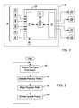
- FIG. 2is a schematic view of the dynamic projection system
- FIG. 3is a flow chart illustrating a method for dynamically projecting information using the dynamic projection system
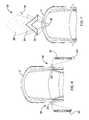
- FIG. 4is a top view of a first exemplary projection profile
- FIG. 5is a top view of a second exemplary projection profile
- FIG. 6is a top view of a third exemplary projection profile
- FIG. 7is a top view of a fourth exemplary projection profile.
- a dynamic projection systemis illustrated and indicated generally by reference number 10 .
- the dynamic projection system 10is shown in use with an exemplary motor vehicle 12 .
- the motor vehicle 12is illustrated as a passenger vehicle.
- the motor vehicle 12may be a truck, sport utility vehicle, van, motor home, or any other type of vehicle without departing from the scope of the present disclosure.
- the motor vehicle 12includes a front 14 , a rear 16 , a left side 18 , and a right side 20 .
- the dynamic projection system 10includes one or more dynamic projectors 22 mounted to an exterior of the motor vehicle 12 .
- the dynamic projection system 10may include one of, or a combination of, a front dynamic projector 22 A, a rear dynamic projector 22 B, a left side dynamic projector 22 C, and a right side dynamic projector 22 D.
- the front dynamic projector 22 Ais mounted to the front 14 of the motor vehicle 12 .
- the rear dynamic projector 22 Bis mounted to the rear 16 of the motor vehicle 12 .
- the left side dynamic projector 22 Cis mounted to the left side 18 of the motor vehicle 12 .
- the right side dynamic projectoris mounted to the right side 20 of the motor vehicle 12 .
- the left and right side projectors 22 C, 22 Dare housed within left and right side view mirrors 24 and 26 , respectively.
- the left and right side projectors 22 C, 22 Dmay be housed within multifunctional electronic armatures that replace the left and right side view mirrors 24 and 26 .
- An example of a multifunctional electronic armatureis shown and described in commonly assigned U.S. application Ser. No. 15/165,022, filed May 26, 2016, the entirety of which is hereby incorporated by reference.
- the dynamic projectors 22 A-Dare preferably laser projectors, such as RGB laser projectors or phosphorus laser projectors, capable of emitting or projecting a projection profile onto a surface.
- each of the dynamic projectors 22 A-Dare in electronic communication with a controller or electronic control unit (ECU) 28 via any wired connection, for example a vehicle bus network.
- the ECU 28is mounted within the motor vehicle 12 and may be a dedicated projector controller or an engine control module, a transmission control module, a body control module, an infotainment control module, etc.
- the ECU 28is a non-generalized, electronic control device having a preprogrammed digital computer or processor 29 , memory or non-transitory computer readable medium 31 used to store data such as control logic, instructions, image data, lookup tables, etc., and a plurality of input/output peripherals or ports 33 .
- the processor 29is configured to execute the control logic or instructions.
- each of the dynamic projectors 22 A-Dmay have a local projector controller in communication with the ECU 28 .
- An example of this controller system for a dynamic projectoris shown and described in commonly assigned U.S. application Ser. No. 15/165,055, filed May 26, 2016, the entirety of which is hereby incorporated by reference.
- the ECU 28is in electronic communication with a plurality of sensors 30 mounted to the motor vehicle 12 .
- the sensors 30are operative to provide information or data signals to the ECU 28 indicative of an operating state of the motor vehicle 12 .
- the sensors 30include a steering wheel angle sensor 32 , a turn signal sensor 34 , a shift sensor 36 , a lighting sensor 38 , a vehicle speed sensor 40 , a door sensor 42 , and a security data receiver 44 .
- the steering wheel angle sensor 32detects or senses a steering wheel angle indicative of a degree of turn of the motor vehicle 12 .
- the turn signal sensor 34detects whether a left or right turn signal has been activated in the motor vehicle 12 .
- the shift sensor 36detects the driving state of the motor vehicle 12 .
- the driving statemay be a one of a park, reverse, neutral, drive, and low drive (PRNDL) vehicle driving state.
- the lighting sensor 38detects a brightness of the environment, i.e. the illumination intensity of the ambient lighting surrounding the motor vehicle 12 .
- the vehicle speed sensor 40detects a vehicle speed of the motor vehicle 12 .
- the door sensor 42detects a status of a vehicle door, such as open or closed, latched or unlatched.
- the security data receiver 44is a wireless receiver configured to detect a security identifier from, for example, a key fob.
- the security identifiermay include a personal identification number that authenticates the owner of the motor vehicle 12 .
- the method 100begins at step 102 when the ECU 28 receives data signals from one of, or a combination of, the plurality of sensors 30 .
- the data signalsare indicative of an operating state of the motor vehicle 12 .
- the data signalsmay include a steering angle detected from the steering wheel angle sensor 32 .
- the data signalsmay include a turn signal activation identifier detected from the turn signal sensor 34 .
- the data signalsmay include a PRNDL status detected from the shift sensor 36 indicative of the driving state of the motor vehicle from one of the park, reverse, neutral, drive, and low drive vehicle driving states.
- the data signalsmay include a lighting status from the lighting sensor 38 indicative of the brightness of the environment of the motor vehicle 12 .
- the data signalsmay include a vehicle speed from the vehicle speed sensor 40 .
- the data signalsmay include a door status from the door sensor 42 indicative of the position of a door of the motor vehicle 12 .
- the data signalsmay include a unique identifier indicative that a key fob associated with the motor vehicle 12 is proximate the motor vehicle 12 .
- the method 100proceeds to step 104 where the ECU 28 determines or generates a projection profile based on the data signals from the plurality of sensors 30 .
- the projection profileis a graphical image or other visual representation of information relating to the particular data signals received by the ECU 28 at step 102 .
- the projection profilequantifies the data signals to inform an individual external to the motor vehicle 12 of a state of the motor vehicle 12 .
- the projection profilepreferably includes a dynamic feature.
- the dynamic featureis a set of graphical images that may be animated by the dynamic projector.
- the method 100then proceeds to step 106 where the dynamic projectors 22 continuously projects the projection profile onto a surface on which the motor vehicle 12 is running. At step 108 the dynamic projectors 22 animate the dynamic feature of the projection profile. The method 100 then repeats, allowing for projection updates as the operating conditions of the motor vehicle 12 change.
- FIG. 4an example of a projection profile is illustrated relative to the motor vehicle 12 and indicated by reference number 200 .
- the projection profile 200is projected from the right side projector 22 D or the left side projector 22 C.
- the projection profile 200is calculated from the sensed steering angle and includes a vector 202 of the motor vehicle 12 projected to a relatively flat surface 204 , such as a road, driveway, parking lot, etc.
- the vector 202is indicative of a path of movement of the motor vehicle 12 .
- the vector 202aligns with a front tire 206 of the motor vehicle 12 .
- the vector 202may align with the front 14 of the motor vehicle 12 .
- the projection profile 200preferably includes a dynamic feature 208 .
- the dynamic feature 208is a set of arrows 210 , 212 that, when animated, travel along a length of the vector 202 over time.
- the dynamic feature 208preferably indicates a direction of travel of the motor vehicle 12 .
- the projection profile 200may be a vector parallel with the motor vehicle 12 .
- FIG. 5another example of a projection profile is illustrated relative to the motor vehicle 12 and indicated by reference number 300 .
- the projection profile 300is projected from the right side projector 22 D or the left side projector 22 C.
- the projection profile 300is calculated from the sensed turn signal indicator and includes an arrow 302 projected to the surface 204 .
- the arrow 302is indicative of the intention of the motor vehicle 12 to turn, based on the activation of the turn signal.
- the dynamic featureis a set of additional arrows 304 , 306 that, when animated, travel away from the motor vehicle 12 .
- FIG. 6another example of a projection profile is illustrated relative to the motor vehicle 12 and indicated by reference number 400 .
- the projection profile 400is projected from the right side projector 22 D and the left side projector 22 C.
- the projection profile 400is calculated from the sensed unique identifier and includes a message 402 projected to the surface 204 .
- the messagemay be personalized based on the personal identification number or a generalized message.
- the dynamic featuremay be animated lettering.
- FIG. 7another example of a projection profile is illustrated relative to the motor vehicle 12 and indicated by reference number 500 .
- the projection profile 500is projected from the front projector 22 A or the rear projector 22 B.
- the projection profile 500is calculated from the vehicle speed and the PRNDL status and includes an arrow 502 projected to the surface 204 .
- the arrow 502is indicative of the intention of the motor vehicle 12 to move either forward when the PRNDL status indicates a drive shift condition or backwards when the PRNDL status indicates a reverse shift position.
- which projector 22 A, 22 B is usedis based on whether the shift condition is drive or reverse.
- the dynamic featureis a set of additional arrows 504 , 506 that, when animated, travel away from the motor vehicle 12 .
- the length of the animationmay be based on the vehicle speed wherein a greater vehicle speed in turn generates additional arrows.
- Each of the projection profiles 200 , 300 , 400 , and 500may further be modified by the lighting status and the door status. For example, if the lighting status is above a brightness threshold, the ECU 28 may determine not to project the projection profile. Likewise, if the door status indicates that the motor vehicle door is open, the ECU 28 may determine not to project the projection profile. Alternatively, a brightness of the projection profile may be a function of the sensed lighting status of the environment. In another example, the projection profile may include a message communicating the door status, such as “door open”.
Landscapes
- Engineering & Computer Science (AREA)
- Physics & Mathematics (AREA)
- General Physics & Mathematics (AREA)
- Mechanical Engineering (AREA)
- Multimedia (AREA)
- Signal Processing (AREA)
- Lighting Device Outwards From Vehicle And Optical Signal (AREA)
Abstract
Description
Claims (21)
Priority Applications (1)
| Application Number | Priority Date | Filing Date | Title |
|---|---|---|---|
| US15/165,738US9827901B1 (en) | 2016-05-26 | 2016-05-26 | System and method for dynamically projecting information from a motor vehicle |
Applications Claiming Priority (1)
| Application Number | Priority Date | Filing Date | Title |
|---|---|---|---|
| US15/165,738US9827901B1 (en) | 2016-05-26 | 2016-05-26 | System and method for dynamically projecting information from a motor vehicle |
Publications (2)
| Publication Number | Publication Date |
|---|---|
| US9827901B1true US9827901B1 (en) | 2017-11-28 |
| US20170341569A1 US20170341569A1 (en) | 2017-11-30 |
Family
ID=60409073
Family Applications (1)
| Application Number | Title | Priority Date | Filing Date |
|---|---|---|---|
| US15/165,738ActiveUS9827901B1 (en) | 2016-05-26 | 2016-05-26 | System and method for dynamically projecting information from a motor vehicle |
Country Status (1)
| Country | Link |
|---|---|
| US (1) | US9827901B1 (en) |
Cited By (8)
| Publication number | Priority date | Publication date | Assignee | Title |
|---|---|---|---|---|
| US20180118095A1 (en)* | 2015-04-10 | 2018-05-03 | Maxell, Ltd. | Image projection apparatus |
| US20180281749A1 (en)* | 2017-04-04 | 2018-10-04 | Volvo Car Corporation | Vehicle information system |
| US20180304820A1 (en)* | 2017-04-19 | 2018-10-25 | Ford Global Technologies, Llc | Vehicle-mounted video projector |
| US10600086B2 (en)* | 2016-03-13 | 2020-03-24 | Adway International, Inc. | System and method for projecting and displaying images |
| US10948148B2 (en)* | 2015-05-26 | 2021-03-16 | Lumileds Llc | Lighting device with multiple-focus mode |
| US11072277B2 (en) | 2019-09-20 | 2021-07-27 | Adway International Inc. | Method and apparatus to dynamically identify a vehicle |
| US20230271548A1 (en)* | 2020-08-05 | 2023-08-31 | Koito Manufacturing Co., Ltd. | Vehicle projection device |
| US20250214616A1 (en)* | 2024-01-03 | 2025-07-03 | Gm Cruise Holdings Llc | Vehicle content item projection |
Families Citing this family (1)
| Publication number | Priority date | Publication date | Assignee | Title |
|---|---|---|---|---|
| CN114604167B (en)* | 2022-03-10 | 2024-05-28 | 武汉理工大学 | Low-illumination environment car lamp projection system for traffic safety |
Citations (16)
| Publication number | Priority date | Publication date | Assignee | Title |
|---|---|---|---|---|
| US5289321A (en) | 1993-02-12 | 1994-02-22 | Secor James O | Consolidated rear view camera and display system for motor vehicle |
| US20020126206A1 (en) | 2001-01-05 | 2002-09-12 | Hunte Stanley G. | Electronic side--view mirrors for motor vehicles using exterior cameras wired to interior monitor |
| US20030146831A1 (en) | 2002-02-05 | 2003-08-07 | Wolfgang Berberich | Parking and/or maneuvering assistance device |
| US6733134B2 (en)* | 2000-11-09 | 2004-05-11 | Astron Group Technologies Sa | Visual signalling device adaptable to a vehicle |
| US20100283590A1 (en)* | 2009-05-08 | 2010-11-11 | Alexander Kirby Tee | Safety light device |
| US20110032484A1 (en)* | 2009-08-07 | 2011-02-10 | Trevor Seal | Apparatus, system, and method for vehicle mounted display device |
| US20110273671A1 (en) | 2010-05-07 | 2011-11-10 | Idesign Max Co., Ltd. | Projector for Casting Light on the Ground beside a Vehicle |
| US8170070B2 (en) | 2007-05-03 | 2012-05-01 | Fairchildd Semiconductor Corporation | Method and circuit for interleaving, serializing and deserializing camera and keypad data |
| US20120315027A1 (en) | 2010-01-15 | 2012-12-13 | Huf Hülsbeck & Fürst Gmbh & Co. Kg | Device for a motor vehicle comprising a movably mounted camera unit and motor vehicle |
| US20130052614A1 (en)* | 2011-08-31 | 2013-02-28 | Pulsar Informatics, Inc. | Driver Performance Metric |
| US20130120572A1 (en) | 2011-11-14 | 2013-05-16 | Hyundai Mobis Co., Ltd. | Parking assistance system using projector and method thereof |
| DE102011119923A1 (en) | 2011-11-28 | 2013-05-29 | Son Hao Vu | Lighting system for air- and land vehicles and working machines for projection of targeted optical guidance or patterns during operation, has integrated control unit which assembles and monitors necessary data for desired operating mode |
| US20130235351A1 (en)* | 2012-03-07 | 2013-09-12 | GM Global Technology Operations LLC | Virtual convertible tops, sunroofs, and back windows, and systems and methods for providing same |
| CN203358457U (en) | 2013-03-25 | 2013-12-25 | 门建 | Vehicle monitoring imaging device |
| US20140028980A1 (en)* | 2012-07-26 | 2014-01-30 | Cloudcar, Inc. | Vehicle content projection |
| US20150022664A1 (en)* | 2012-01-20 | 2015-01-22 | Magna Electronics Inc. | Vehicle vision system with positionable virtual viewpoint |
- 2016
- 2016-05-26USUS15/165,738patent/US9827901B1/enactiveActive
Patent Citations (16)
| Publication number | Priority date | Publication date | Assignee | Title |
|---|---|---|---|---|
| US5289321A (en) | 1993-02-12 | 1994-02-22 | Secor James O | Consolidated rear view camera and display system for motor vehicle |
| US6733134B2 (en)* | 2000-11-09 | 2004-05-11 | Astron Group Technologies Sa | Visual signalling device adaptable to a vehicle |
| US20020126206A1 (en) | 2001-01-05 | 2002-09-12 | Hunte Stanley G. | Electronic side--view mirrors for motor vehicles using exterior cameras wired to interior monitor |
| US20030146831A1 (en) | 2002-02-05 | 2003-08-07 | Wolfgang Berberich | Parking and/or maneuvering assistance device |
| US8170070B2 (en) | 2007-05-03 | 2012-05-01 | Fairchildd Semiconductor Corporation | Method and circuit for interleaving, serializing and deserializing camera and keypad data |
| US20100283590A1 (en)* | 2009-05-08 | 2010-11-11 | Alexander Kirby Tee | Safety light device |
| US20110032484A1 (en)* | 2009-08-07 | 2011-02-10 | Trevor Seal | Apparatus, system, and method for vehicle mounted display device |
| US20120315027A1 (en) | 2010-01-15 | 2012-12-13 | Huf Hülsbeck & Fürst Gmbh & Co. Kg | Device for a motor vehicle comprising a movably mounted camera unit and motor vehicle |
| US20110273671A1 (en) | 2010-05-07 | 2011-11-10 | Idesign Max Co., Ltd. | Projector for Casting Light on the Ground beside a Vehicle |
| US20130052614A1 (en)* | 2011-08-31 | 2013-02-28 | Pulsar Informatics, Inc. | Driver Performance Metric |
| US20130120572A1 (en) | 2011-11-14 | 2013-05-16 | Hyundai Mobis Co., Ltd. | Parking assistance system using projector and method thereof |
| DE102011119923A1 (en) | 2011-11-28 | 2013-05-29 | Son Hao Vu | Lighting system for air- and land vehicles and working machines for projection of targeted optical guidance or patterns during operation, has integrated control unit which assembles and monitors necessary data for desired operating mode |
| US20150022664A1 (en)* | 2012-01-20 | 2015-01-22 | Magna Electronics Inc. | Vehicle vision system with positionable virtual viewpoint |
| US20130235351A1 (en)* | 2012-03-07 | 2013-09-12 | GM Global Technology Operations LLC | Virtual convertible tops, sunroofs, and back windows, and systems and methods for providing same |
| US20140028980A1 (en)* | 2012-07-26 | 2014-01-30 | Cloudcar, Inc. | Vehicle content projection |
| CN203358457U (en) | 2013-03-25 | 2013-12-25 | 门建 | Vehicle monitoring imaging device |
Cited By (13)
| Publication number | Priority date | Publication date | Assignee | Title |
|---|---|---|---|---|
| US11340089B2 (en) | 2015-04-10 | 2022-05-24 | Maxell, Ltd. | Vehicle having a projector for projecting an image on a road surface |
| US12196570B2 (en) | 2015-04-10 | 2025-01-14 | Maxell, Ltd. | Image projection apparatus, of a vehicle, that projects an image on a surface |
| US20180118095A1 (en)* | 2015-04-10 | 2018-05-03 | Maxell, Ltd. | Image projection apparatus |
| US10794719B2 (en)* | 2015-04-10 | 2020-10-06 | Maxell, Ltd. | Vehicle image projection apparatus that projects an image in the front and back of a vehicle based on sensor information |
| US10948148B2 (en)* | 2015-05-26 | 2021-03-16 | Lumileds Llc | Lighting device with multiple-focus mode |
| US10600086B2 (en)* | 2016-03-13 | 2020-03-24 | Adway International, Inc. | System and method for projecting and displaying images |
| US20180281749A1 (en)* | 2017-04-04 | 2018-10-04 | Volvo Car Corporation | Vehicle information system |
| US10394112B2 (en)* | 2017-04-19 | 2019-08-27 | Ford Global Technologies, Llc | Vehicle including video projector mounted to lift gate or roof |
| US20180304820A1 (en)* | 2017-04-19 | 2018-10-25 | Ford Global Technologies, Llc | Vehicle-mounted video projector |
| US11072277B2 (en) | 2019-09-20 | 2021-07-27 | Adway International Inc. | Method and apparatus to dynamically identify a vehicle |
| US20230271548A1 (en)* | 2020-08-05 | 2023-08-31 | Koito Manufacturing Co., Ltd. | Vehicle projection device |
| US12319197B2 (en)* | 2020-08-05 | 2025-06-03 | Koito Manufacturing Co., Ltd. | Vehicle projection device |
| US20250214616A1 (en)* | 2024-01-03 | 2025-07-03 | Gm Cruise Holdings Llc | Vehicle content item projection |
Also Published As
| Publication number | Publication date |
|---|---|
| US20170341569A1 (en) | 2017-11-30 |
Similar Documents
| Publication | Publication Date | Title |
|---|---|---|
| US9827901B1 (en) | System and method for dynamically projecting information from a motor vehicle | |
| US11565690B2 (en) | Vehicular driving assistance system that controls a vehicle in accordance with parameters preferred by an identified driver | |
| US10899365B2 (en) | Parking support information display method and parking support device | |
| JP5962319B2 (en) | Vehicle control device | |
| US11628766B2 (en) | Notification device | |
| JP6384949B2 (en) | Vehicle driving support device | |
| US10293749B2 (en) | Vehicle control device and vehicle | |
| US9987985B2 (en) | Vehicle and method for controlling vehicle | |
| US20150353132A1 (en) | Motor vehicle system and method | |
| CN112644378B (en) | Vehicle alarm device | |
| TW201821311A (en) | Method for automatically setting locomotive speed | |
| US10315560B2 (en) | System and method for safety improvement during operation of a motor vehicle | |
| JP6083482B2 (en) | Vehicle control device | |
| US11257372B2 (en) | Reverse-facing anti-collision system | |
| EP4370397B1 (en) | A method for controlling a maximum allowed speed of an autonomous vehicle | |
| JP6332416B2 (en) | Vehicle control device | |
| KR20230074481A (en) | Information processing device, information processing method, program and projection device | |
| CN110770810A (en) | Ambient monitoring of autonomous vehicles | |
| CN116935694A (en) | System and method for predicting and displaying side blind zone entry alarms | |
| CN111717160B (en) | Transportation device and vehicle | |
| JP6757585B2 (en) | Display device | |
| CN113619577A (en) | Driving assistance system and driving assistance method | |
| JP6354745B2 (en) | Blinker control device | |
| CN117656996A (en) | Warning indicators and associated vehicles and methods | |
| GB2416901A (en) | Vehicle parking assistant that calculates and displays to the driver the position needed to reverse the steering lock when parallel parking |
Legal Events
| Date | Code | Title | Description |
|---|---|---|---|
| AS | Assignment | Owner name:DURA OPERATING, LLC, MICHIGAN Free format text:ASSIGNMENT OF ASSIGNORS INTEREST;ASSIGNORS:THOMPSON, AARON EVANS;UNVEREN, CUMHUR;SIGNING DATES FROM 20160509 TO 20161012;REEL/FRAME:040074/0183 | |
| STCF | Information on status: patent grant | Free format text:PATENTED CASE | |
| AS | Assignment | Owner name:DUS OPERATING INC., MICHIGAN Free format text:ASSIGNMENT OF ASSIGNORS INTEREST;ASSIGNOR:DURA OPERATING, LLC;REEL/FRAME:055130/0931 Effective date:20200605 | |
| AS | Assignment | Owner name:WELLS FARGO BANK, NATIONAL ASSOCIATION, AS AGENT, ILLINOIS Free format text:SECURITY AGREEMENT;ASSIGNOR:DUS OPERATING INC.;REEL/FRAME:055228/0843 Effective date:20210205 Owner name:BLUE TORCH FINANCE LLC, AS COLLATERAL AGENT, NEW YORK Free format text:PATENT AND TRADEMARK SECURITY AGREEMENT;ASSIGNORS:DURA AUTOMOTIVE HOLDINGS U.K., LTD;DURA AUTOMOTIVE SYSTEMS GMBH;DUS OPERATING INC.;REEL/FRAME:055224/0756 Effective date:20210205 | |
| MAFP | Maintenance fee payment | Free format text:PAYMENT OF MAINTENANCE FEE, 4TH YEAR, LARGE ENTITY (ORIGINAL EVENT CODE: M1551); ENTITY STATUS OF PATENT OWNER: LARGE ENTITY Year of fee payment:4 | |
| AS | Assignment | Owner name:DUS OPERATING, INC., MICHIGAN Free format text:RELEASE OF PATENT AND TRADEMARK SECURITY AGREEMENT;ASSIGNOR:BLUE TORCH FINANCE LLC;REEL/FRAME:058671/0253 Effective date:20220103 Owner name:DURA AUTOMOTIVE SYSTEMS GMBH, GERMANY Free format text:RELEASE OF PATENT AND TRADEMARK SECURITY AGREEMENT;ASSIGNOR:BLUE TORCH FINANCE LLC;REEL/FRAME:058671/0253 Effective date:20220103 Owner name:DURA AUTOMOTIVE HOLDINGS U.K., LTD, UNITED KINGDOM Free format text:RELEASE OF PATENT AND TRADEMARK SECURITY AGREEMENT;ASSIGNOR:BLUE TORCH FINANCE LLC;REEL/FRAME:058671/0253 Effective date:20220103 | |
| AS | Assignment | Owner name:DUS OPERATING INC., MICHIGAN Free format text:RELEASE BY SECURED PARTY;ASSIGNOR:WELLS FARGO BANK, NATIONAL ASSOCIATION;REEL/FRAME:059783/0288 Effective date:20220413 | |
| AS | Assignment | Owner name:NEW EAGLE, LLC, MICHIGAN Free format text:ASSIGNMENT OF ASSIGNORS INTEREST;ASSIGNOR:DUS OPERATING INC.;REEL/FRAME:061062/0852 Effective date:20220513 | |
| FEPP | Fee payment procedure | Free format text:MAINTENANCE FEE REMINDER MAILED (ORIGINAL EVENT CODE: REM.); ENTITY STATUS OF PATENT OWNER: LARGE ENTITY |