US9827823B2 - Stability control system - Google Patents
Stability control systemDownload PDFInfo
- Publication number
- US9827823B2 US9827823B2US15/146,260US201615146260AUS9827823B2US 9827823 B2US9827823 B2US 9827823B2US 201615146260 AUS201615146260 AUS 201615146260AUS 9827823 B2US9827823 B2US 9827823B2
- Authority
- US
- United States
- Prior art keywords
- frame
- caster
- wheelchair
- casters
- coupled
- Prior art date
- Legal status (The legal status is an assumption and is not a legal conclusion. Google has not performed a legal analysis and makes no representation as to the accuracy of the status listed.)
- Active
Links
Images


Classifications
- B—PERFORMING OPERATIONS; TRANSPORTING
- B60—VEHICLES IN GENERAL
- B60G—VEHICLE SUSPENSION ARRANGEMENTS
- B60G21/00—Interconnection systems for two or more resiliently-suspended wheels, e.g. for stabilising a vehicle body with respect to acceleration, deceleration or centrifugal forces
- B60G21/02—Interconnection systems for two or more resiliently-suspended wheels, e.g. for stabilising a vehicle body with respect to acceleration, deceleration or centrifugal forces permanently interconnected
- B60G21/04—Interconnection systems for two or more resiliently-suspended wheels, e.g. for stabilising a vehicle body with respect to acceleration, deceleration or centrifugal forces permanently interconnected mechanically
- A—HUMAN NECESSITIES
- A61—MEDICAL OR VETERINARY SCIENCE; HYGIENE
- A61G—TRANSPORT, PERSONAL CONVEYANCES, OR ACCOMMODATION SPECIALLY ADAPTED FOR PATIENTS OR DISABLED PERSONS; OPERATING TABLES OR CHAIRS; CHAIRS FOR DENTISTRY; FUNERAL DEVICES
- A61G5/00—Chairs or personal conveyances specially adapted for patients or disabled persons, e.g. wheelchairs
- A61G5/04—Chairs or personal conveyances specially adapted for patients or disabled persons, e.g. wheelchairs motor-driven
- A61G5/041—Chairs or personal conveyances specially adapted for patients or disabled persons, e.g. wheelchairs motor-driven having a specific drive-type
- A61G5/043—Mid wheel drive
- A—HUMAN NECESSITIES
- A61—MEDICAL OR VETERINARY SCIENCE; HYGIENE
- A61G—TRANSPORT, PERSONAL CONVEYANCES, OR ACCOMMODATION SPECIALLY ADAPTED FOR PATIENTS OR DISABLED PERSONS; OPERATING TABLES OR CHAIRS; CHAIRS FOR DENTISTRY; FUNERAL DEVICES
- A61G5/00—Chairs or personal conveyances specially adapted for patients or disabled persons, e.g. wheelchairs
- A61G5/06—Chairs or personal conveyances specially adapted for patients or disabled persons, e.g. wheelchairs with obstacle mounting facilities, e.g. for climbing stairs, kerbs or steps
- A—HUMAN NECESSITIES
- A61—MEDICAL OR VETERINARY SCIENCE; HYGIENE
- A61G—TRANSPORT, PERSONAL CONVEYANCES, OR ACCOMMODATION SPECIALLY ADAPTED FOR PATIENTS OR DISABLED PERSONS; OPERATING TABLES OR CHAIRS; CHAIRS FOR DENTISTRY; FUNERAL DEVICES
- A61G5/00—Chairs or personal conveyances specially adapted for patients or disabled persons, e.g. wheelchairs
- A61G5/10—Parts, details or accessories
- A61G5/1078—Parts, details or accessories with shock absorbers or other suspension arrangements between wheels and frame
- A—HUMAN NECESSITIES
- A61—MEDICAL OR VETERINARY SCIENCE; HYGIENE
- A61G—TRANSPORT, PERSONAL CONVEYANCES, OR ACCOMMODATION SPECIALLY ADAPTED FOR PATIENTS OR DISABLED PERSONS; OPERATING TABLES OR CHAIRS; CHAIRS FOR DENTISTRY; FUNERAL DEVICES
- A61G5/00—Chairs or personal conveyances specially adapted for patients or disabled persons, e.g. wheelchairs
- A61G5/10—Parts, details or accessories
- A61G5/1089—Anti-tip devices
- B—PERFORMING OPERATIONS; TRANSPORTING
- B60—VEHICLES IN GENERAL
- B60G—VEHICLE SUSPENSION ARRANGEMENTS
- B60G17/00—Resilient suspensions having means for adjusting the spring or vibration-damper characteristics, for regulating the distance between a supporting surface and a sprung part of vehicle or for locking suspension during use to meet varying vehicular or surface conditions, e.g. due to speed or load
- B60G17/005—Suspension locking arrangements
- B—PERFORMING OPERATIONS; TRANSPORTING
- B60—VEHICLES IN GENERAL
- B60G—VEHICLE SUSPENSION ARRANGEMENTS
- B60G21/00—Interconnection systems for two or more resiliently-suspended wheels, e.g. for stabilising a vehicle body with respect to acceleration, deceleration or centrifugal forces
- B60G21/005—Interconnection systems for two or more resiliently-suspended wheels, e.g. for stabilising a vehicle body with respect to acceleration, deceleration or centrifugal forces transversally
- B—PERFORMING OPERATIONS; TRANSPORTING
- B60—VEHICLES IN GENERAL
- B60G—VEHICLE SUSPENSION ARRANGEMENTS
- B60G2204/00—Indexing codes related to suspensions per se or to auxiliary parts
- B60G2204/40—Auxiliary suspension parts; Adjustment of suspensions
- B60G2204/46—Means for locking the suspension
- B60G2204/4605—Means for locking the suspension hydraulically, e.g. interrupting communication between the chambers of a hydraulic cylinder
- B—PERFORMING OPERATIONS; TRANSPORTING
- B60—VEHICLES IN GENERAL
- B60G—VEHICLE SUSPENSION ARRANGEMENTS
- B60G2300/00—Indexing codes relating to the type of vehicle
- B60G2300/24—Wheelchairs
- B—PERFORMING OPERATIONS; TRANSPORTING
- B60—VEHICLES IN GENERAL
- B60G—VEHICLE SUSPENSION ARRANGEMENTS
- B60G2300/00—Indexing codes relating to the type of vehicle
- B60G2300/40—Variable track or wheelbase vehicles
- B60G2300/402—Extra load carrying wheels, e.g. tag axles
- Y—GENERAL TAGGING OF NEW TECHNOLOGICAL DEVELOPMENTS; GENERAL TAGGING OF CROSS-SECTIONAL TECHNOLOGIES SPANNING OVER SEVERAL SECTIONS OF THE IPC; TECHNICAL SUBJECTS COVERED BY FORMER USPC CROSS-REFERENCE ART COLLECTIONS [XRACs] AND DIGESTS
- Y10—TECHNICAL SUBJECTS COVERED BY FORMER USPC
- Y10S—TECHNICAL SUBJECTS COVERED BY FORMER USPC CROSS-REFERENCE ART COLLECTIONS [XRACs] AND DIGESTS
- Y10S180/00—Motor vehicles
- Y10S180/907—Motorized wheelchairs
Definitions
- Wheelchairs and scootersare an important means of transportation for a significant portion of society. Whether manual or powered, these vehicles provide an important degree of independence for those they assist. However, this degree of independence can be limited if the wheelchair is required to traverse obstacles such as, for example, curbs that are commonly present at sidewalks, driveways, and other paved surface interfaces. This degree of independence can also be limited if the vehicle is required to ascend inclines or descend declines.
- Most wheelchairshave front and rear casters to stabilize the chair from tipping forward or backward and to ensure that the drive wheels are always in contact with the ground.
- the caster wheelsare typically much smaller than the driving wheels and located both forward and rearward of the drive wheels. Though this configuration provides the wheelchair with greater stability, it can hamper the wheelchair's ability to climb over obstacles such as, for example, curbs or the like, because the size of the front casters limits the height of the obstacle that can be traversed.
- a suspension for a vehicleincludes, for example, a stabilizing assembly.
- the stabilizing assemblyinhibits tipping of a frame of the vehicle when tipping of the frame is detected.
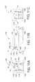
- FIG. 1Ais an illustration of a rear of an embodiment of a mid-wheel drive wheelchair
- FIG. 1Bis a view taken along lines 1 B- 1 B in FIG. 1A , illustrating a side of the mid-wheel drive wheelchair;
- FIG. 1Cis a view taken along lines 1 C- 1 C in FIG. 1B , illustrating a front of the mid-wheel drive wheelchair;
- FIG. 2is a flow chart that illustrates an embodiment of a method of controlling tipping of a mid-wheel drive wheelchair frame
- FIGS. 3A-3Cillustrate the wheelchair of FIGS. 1A-1C , where one rear caster has moved downward relative to a frame;
- FIGS. 4A-4Cillustrate the wheelchair of FIGS. 1A-1C , where the wheelchair is exhibiting a tipping behavior
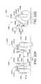
- FIG. 5is an illustration of an embodiment of a wheelchair with a fluid cylinder stabilizing assembly
- FIG. 6is an illustration of an embodiment of a wheelchair with a fluid cylinder with spring return stabilizing assembly
- FIGS. 7A-7Cillustrate an embodiment of a mid-wheel drive wheelchair that is similar to the wheelchair shown in FIGS. 1A-1C where two stabilizing members are linked;
- FIGS. 8A-8Cillustrate an embodiment of a mid-wheel drive wheelchair that is similar to the wheelchair shown in FIGS. 1A-1C that includes a single stabilizing member or assembly;
- FIGS. 9A-9Cillustrate an embodiment of a mid-wheel drive wheelchair that is similar to the wheelchair shown in FIGS. 1A-1C where two triggers or sensors are linked;
- FIGS. 10A-10Cillustrate an embodiment of a mid-wheel drive wheelchair that is similar to the wheelchair shown in FIGS. 1A-1C that includes a single trigger or sensor;
- FIGS. 11A-11Cillustrate an embodiment of a mid-wheel drive wheelchair that is similar to the wheelchair shown in FIGS. 1A-1C that includes a rear caster position sensing linkage coupled to a single trigger or sensor that indicates when both rear casters drop relative to a frame;
- FIGS. 12A-12Cillustrate the wheelchair of FIGS. 11A-11C , where one rear caster has moved downward relative to a frame;
- FIGS. 13A-13Cillustrate the wheelchair of FIGS. 11A-11C , where the wheelchair is exhibiting a tipping behavior
- FIGS. 14A-14Cillustrate an embodiment of a mid-wheel drive wheelchair that is similar to the wheelchair shown in FIGS. 1A-1C that includes a rear caster position sensing linkage coupled to a pair of triggers or sensor that indicates when both rear casters drop relative to a frame;
- FIGS. 15A-15Cillustrate the wheelchair of FIGS. 14A-14C , where one rear caster has moved downward relative to a frame;
- FIGS. 16A-16Cillustrate the wheelchair of FIGS. 14A-14C , where the wheelchair is exhibiting a tipping behavior
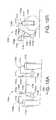
- FIG. 17Aillustrates a rear view of an embodiment of a rear caster suspension with a rear caster position sensing arrangement
- FIG. 17Bis a view taken along lines 17 B- 17 B in FIG. 17A , illustrating a side view of the rear caster suspension and rear caster position sensing arrangement;
- FIG. 17Cis a view taken along lines 17 C- 17 C in FIG. 17A , illustrating a top view of the rear caster suspension and rear caster position sensing arrangement;
- FIGS. 18A and 18Billustrate the rear caster suspension and rear caster position sensing arrangement of FIGS. 17A-17C , where one rear caster has moved downward;
- FIGS. 19A and 19Billustrate the rear caster suspension and rear caster position sensing arrangement of FIGS. 17A-17C , where both rear casters have moved downward;
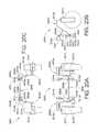
- FIGS. 20A-20Cillustrate an embodiment of a rear caster suspension and rear caster position sensing arrangement that is similar to the rear caster suspension and rear caster position sensing arrangement shown in FIGS. 17A-17C where movement of a first rear caster pivot arm depends on a position of a second rear caster pivot arm;
- FIGS. 21A and 21Billustrate the rear caster suspension and rear caster position sensing arrangement of FIGS. 20A-20C , where one rear caster has moved downward;
- FIGS. 22A and 22Billustrate the rear caster suspension and rear caster position sensing arrangement of FIGS. 20A-20C , where further downward movement of one rear caster is inhibited by a second rear caster;
- FIG. 23Aillustrates a rear of an embodiment of a rear caster suspension and rear caster position sensing arrangement
- FIG. 23Bis a view taken along lines 23 B- 23 B in FIG. 23A , illustrating a side of the rear caster suspension and rear caster position sensing arrangement;
- FIG. 23Cis a view taken along lines 23 C- 23 C in FIG. 23A , illustrating a top of the rear caster suspension and rear caster position sensing arrangement;
- FIGS. 24A-24Cillustrate the rear caster suspension and rear caster position sensing arrangement of FIGS. 23A-23C , where downward movement of one rear caster is inhibited by a second rear caster;
- FIGS. 25A-25Cillustrate an embodiment of a rear caster suspension and rear caster position sensing arrangement that is similar to the rear caster suspension and rear caster position sensing arrangement of FIGS. 23A-23C , where the rear casters are connected to a pivotable arm;
- FIG. 26illustrates an embodiment of a mid-wheel drive wheelchair that includes a tip or stability control system and front caster pivot arm that are coupled to drive assemblies;
- FIG. 27illustrates an embodiment of a mid-wheel drive wheelchair that includes a tip or stability control system and front caster pivot arms that are coupled to drive assemblies;
- FIG. 28illustrates an embodiment of a mid-wheel drive wheelchair that includes a tip or stability control system and front caster pivot arms that are coupled to drive assemblies;
- FIG. 29illustrates an embodiment of a mid-wheel drive wheelchair that includes a tip or stability control system and front caster pivot arms that are coupled to drive assemblies;
- FIG. 30illustrates an embodiment of a mid-wheel drive wheelchair that includes a tip or stability control system and front caster pivot arms that are coupled to drive assemblies;
- FIG. 31illustrates an embodiment of a mid-wheel drive wheelchair that includes a tip or stability control system and front caster pivot arms that are coupled to drive assemblies;
- FIG. 32is a perspective view of an embodiment of a mid-wheel drive wheelchair that includes a tip or stability control system
- FIG. 33is a side view of the mid-wheel drive wheelchair of FIG. 32 ;
- FIG. 34is a view taken along lines 34 - 34 in FIG. 33 ;
- FIG. 35is a view taken along lines 35 - 35 in FIG. 33 ;
- FIG. 36is a view taken along lines 36 - 33 in FIG. 33 ;
- FIG. 37is a view taken along lines 37 - 37 in FIG. 33 ;
- FIG. 38is a view of the wheelchair of FIG. 32 with components removed;
- FIG. 39is a side view of the mid-wheel drive wheelchair with components removed of FIG. 38 ;
- FIG. 40is a view taken along lines 40 - 40 in FIG. 39 ;
- FIG. 41is a view taken along lines 41 - 41 in FIG. 40 ;
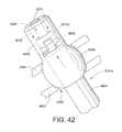
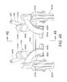
- FIG. 42is an enlarged portion of FIG. 38 as indicated by reference FIG. 42 in FIG. 38 ;
- FIG. 43is a schematic illustration of a vibration damping assembly
- FIG. 44illustrates a perspective view of a rear caster position sensing arrangement and rear caster suspension of the wheelchair illustrated by FIG. 32 ;
- FIG. 45is a side view of the rear caster position sensing arrangement and rear caster suspension of FIG. 44 ;
- FIG. 46is a view taken along lines 46 - 46 in FIG. 45 ;
- FIG. 47is a view taken along lines 47 - 47 in FIG. 45 ;
- FIG. 48is a view taken along lines 48 - 48 in FIG. 46 ;
- FIG. 49is a view taken along lines 49 - 49 in FIG. 48 ;
- FIG. 49Ais a view similar to FIG. 49 , where the rear caster position sensing arrangement has moved to an engaged position;
- FIG. 50is a view taken along lines 50 - 50 in FIG. 45 .
- suspension systemsfor vehicles, such as, wheelchairs, including, but not limited to mid-wheel drive wheelchairs, scooters, and other personal mobility vehicles.
- the drawingsillustrate the suspension systems on mid-wheel drive wheelchairs.
- the described suspensionscan be implemented on any personal mobility vehicle, including scooters and rear drive wheelchairs.
- the suspension systemsinclude a tip or stability control system.
- the control systemincludes a trigger or sensor for sensing when conditions exist that may cause the vehicle to exhibit a tipping behavior, which can be either forward or rearward, and a stabilizing member or assembly that stabilizes the suspension system to prevent any further tipping behavior.
- the trigger or sensoralso senses when the vehicle is no longer subject to conditions that may cause it to exhibit a tipping behavior and causes the stabilizing member or assembly to no longer inhibit movement of the suspension system.
- One feature of some control system embodiments disclosed hereinis that upward movement of one front caster is inhibited to prevent tipping only if upward movement of the other front caster is also inhibited.
- Another feature of some control system embodiments disclosed hereinis that the relative positions of two rear casters are sensed to determine a tipping behavior. For example, a tipping behavior may be indicated only when both rear casters move downward relative to a frame.
- FIGS. 1A, 1B, and 1Cschematically illustrate a mid-wheel drive wheelchair 100 that includes a tip or stability control system that comprises one or more sensors 112 and one or more stabilizing members or assemblies 114 .
- the control system 100can also be applied to a wide variety of other vehicles, including but not limited to, rear drive wheel chairs, front drive wheel chairs, scooters, and other personal mobility vehicles.
- the wheelchair 100includes a frame 102 , a seat 104 supported by the frame, first and second drive wheels 106 that support the frame, first and second front casters 108 a , 108 b , first and second rear casters 110 a , 110 b , one or more sensors 112 , and one or more stabilizing members or assemblies 114 .
- the term “frame”refers to any component or combination of components that are configured for mounting of a drive assembly and a caster pivot arm.
- the first and second front casters 108 a , 108 bare coupled to the frame 102 such that the front casters are moveable upwardly and downwardly with respect to the frame as indicated by double arrow 116 .
- the front castersare independently coupled to the frame 102 by separate pivot arms 118 a , 118 b .
- the pivot arms 118 a , 118 bare coupled such that movement of one pivot arm is transferred to the other pivot arm.
- a torsion barmay couple the pivot arms 108 a , 108 b .
- the first and second rear casters 110 a , 110 bare coupled to the frame 102 such that the rear casters are moveable upwardly and downwardly with respect to the frame.
- the rear castersare independently coupled to the frame 102 by separate rear caster pivot arms 120 a , 120 b .
- the rear caster pivot arms 120 a , 120 bare coupled such that movement of one pivot arm is transferred to the other pivot arm (See the embodiment of FIG. 23 for example).
- One stabilizing member 114is coupled to each front caster pivot arms 118 a , 118 b and to the frame 102 .
- any number of stabilizing members 114can be used, may take any form, and may be coupled to the front caster pivot arm and the frame in any manner that allows the stabilizing member or members to inhibit movement of one or more of the front caster pivot arms with respect to the frame in at least one direction.
- Examples of stabilizing members that may be usedinclude, but are not limited to, the stabilizing members disclosed herein and the locking members disclosed in U.S. Pat. No. 6,851,711 to Goertzen et al, United States Patent Application Publication No. 2004/0150204, and United States Patent Application Publication No. 2005/0151360 to Bertrand et al., which are all incorporated herein by reference in their entireties.
- One trigger or sensor 112is coupled to each of the rear caster pivot arms 120 a,b in the example illustrated by FIGS. 1A, 1B, and 1C .
- any number of triggers or sensors 112can be used, may take any form and may be positioned in any way that allows tipping of the frame 102 to be sensed.
- Examples of triggers or sensors that may be usedinclude, but are not limited to, the triggers or sensors disclosed herein and the triggers or sensors disclosed in U.S. Pat. No. 6,851,711 to Goertzen et al, United States Patent Application Publication No. 2004/0150204, and United States Patent Application Publication No. 2005/0151360 to Bertrand et al.
- Tippingmay be sensed in ways that are unrelated to movement of the rear casters relative to the frame. Examples of ways a tipping behavior may be sensed include, but are not limited to, the ways tipping is sensed in U.S. Pat. No. 6,851,711 to Goertzen et al, United States Patent Application Publication No. 2004/0150204, and United States Patent Application Publication No. 2005/0151360 to Bertrand et al.
- FIG. 2is a flow chart that illustrates an embodiment of a method 200 of stabilizing a mid-wheel drive wheelchair frame.
- upward and downward movement of the front casters 108 a , 108 bis allowed (block 202 ) when at least one rear caster 110 a , 110 b is in a normal operating position.
- the front casters 108 a , 108 bare locked (block 204 ) against at least upward movement relative to the frame.
- the front casters 108 a , 108 bmay be locked against both upward and downward movement or only against upward movement.
- Normal operating positions of the rear casters 110 a and 110 binclude the positions of the rear casters when the wheelchair is stationary on level ground (referred to herein as the stationary, level ground position). Normal operating positions of the rear casters 110 a and 110 b also include any position of the rear casters relative to the frame where the rear caster(s) are rotated as indicated by arrow 70 in FIG. 1B . Normal operating positions of the rear casters 110 a , 110 b also include any positions where the rear caster(s) are rotated relative to the frame 102 as indicated by arrow 72 by less than a predetermined distance or angle below the stationary, level ground position.
- the predetermined distance or angle from the stationary, level ground position in the direction indicated by arrow 72corresponds to a distance or angle that is indicative of a tipping behavior of the wheelchair.
- movement of the rear caster(s) relative to the frame in the direction indicated by arrow 72 that is greater than 1 ⁇ 2 inchmay be indicative of tipping of the wheelchair and out of the normal operating position of the rear casters.
- the normal operating position of the rear casters 110 a and 110 bwill vary from one wheelchair to another.
- FIGS. 1, 3 and 4illustrate a 100 wheelchair with a stabilizing assembly 114 that inhibits upward movement of the first and second front casters 108 a , 108 b with respect to the wheelchair frame 102 based on movement of first and second rear casters 110 a , 110 b with respect to the wheelchair frame.
- the stabilizing assembly 114allows upward and downward movement (as indicated by double arrow 116 ) of the first and second front casters 108 a , 108 b relative to the frame 102 when the first and second rear casters 110 a , 110 b are in normal operating positions relative to the frame.
- FIGS. 3A, 3B, and 3Cillustrate the wheelchair 100 where the rear caster 110 a is in a normal operating position and the rear caster 110 b has dropped below the range of normal operating positions.
- This conditionmay occur when one of the rear casters falls into a depression 302 as illustrated by FIGS. 3A, 3B, and 3C .
- This conditionmay also occur when the wheelchair travels laterally along an inclined surface.
- both of the stabilizing members 114continue to allow upward and downward movement of the first and second front casters 108 a , 108 b relative to the frame 102 .
- FIGS. 4A, 4B, and 4Cillustrate the wheelchair 100 exhibiting a tipping behavior.
- the frame 102 of the wheelchair 100is pitched forward toward the front casters 108 a , 108 b .
- the rear casters 110 a , 110 bmove downward relative to the frame 102 to maintain contact with the ground.
- This downward movementpositions both of the rear casters 110 a , 110 b below the range of normal operating positions relative to the frame 102 .
- the sensors or triggers 112sense that the rear casters 110 a , 110 b are both below the range of normal operating positions and cause the stabilizing members 114 to engage.
- engagement of the stabilizing assemblieslocks the first and second front casters 108 a , 108 b against upward movement relative to the frame, but allow the front casters to move downward as indicated by arrow 400 when the stabilizing assembly is engaged.
- the stabilizing assembly 114locks the front caster pivot arms against both upward and downward movement with respect to the pivot arm when engaged.
- engagement of the stabilizing assemblies 114greatly increase the amount of force required to move the front casters upward with respect to the frame.
- engagement of the stabilizing assemblies 114causes the stabilizing assemblies to apply additional force to move the front casters downward relative to the frame and return the frame to a normal operating position. When one or more of the rear casters return to a normal operating position relative to the frame, the sensors or triggers 112 disengage the stabilizing assembly to allow upward and downward movement of the first and second front casters relative to the frame.
- the stabilizing member, stabilizing members, or stabilizing assembly 114 or assembliescan take a wide variety of different forms.
- the stabilizing assembly 114may be a fluid cylinder 500 as illustrated by FIG. 5 .
- One fluid cylinder 500may be coupled between each front caster 108 a , 108 b at connection 501 and the frame 102 at connection 503 , or a single fluid cylinder may be coupled between the front casters and the frame.
- “coupled”refers to both direct coupling of two or more components or the indirect coupling of components such as through one or more intermediary components or structures.
- the fluid cylinder 500includes a piston 502 , a housing 504 that defines a piston chamber 506 , a rod 508 , and a valve 510 .
- the rod 508extends into the housing 504 and is connected to the piston.
- the piston 502divides the chamber 506 into two compartments 512 , 514 .
- the valve 510selectively allows fluid to flow between the two compartments when the valve is open and prevents flow between the two compartments when the valve is closed. As such, the rod 508 can move into and out of the housing 504 when the valve 510 is open and the position of the piston 502 and the rod is substantially fixed when the valve is closed.
- the valve 510When the valve 510 is open, the movement of the fluid between the chambers 512 , 514 and through the valve 510 provides a damping effect. As such, the cylinder 500 acts as a shock absorber when the valve is open and damps upward and downward movement of the front caster. In one embodiment, when the valve is “closed” fluid is allowed flow from the compartment 512 to the compartment 514 , but not from the compartment 514 to the compartment 512 . As such, the rod 508 may be moved into the housing 504 , but not out the housing when the valve 510 is closed. When the valve 510 is closed, the cylinder 500 damps downward movement of the front caster and inhibits upward movement of the front caster.
- One acceptable fluid cylinder that may be usedis model number Koa8kx-2-06-304/000N from Easylift.
- FIG. 6illustrates a cylinder 600 that is similar to the cylinder 500 illustrated in FIG. 5 , but includes a spring 602 that biases or returns the rod 508 to a retracted position.
- the actuator 600biases the front caster toward contact with the ground only when the valve 510 is open.
- the actuator 600biases the front caster toward contact with the ground when the valve 510 is open or closed.
- One acceptable fluid cylinder with a spring returnthat may be used is model number k0m2pm2-060-345-002/50N from Easylift.
- the stabilizing cylinders 500 , 600 illustrated by FIGS. 5 and 6are two examples of the wide variety of different stabilizing assemblies 114 that can be used. Any arrangement capable of inhibiting upward and/or downward movement of a front caster relative to a frame can be used. As noted above, any of the arrangements for inhibiting movement of a front caster with respect to a frame disclosed in U.S. Pat. No. 6,851,711 to Goertzen et al., United States Patent Application Publication No.: 2004/0150204 to Goertzen et al., and United States Patent Application Publication No.: 2005/0151360 to Bertrand et al. can be used.
- Stabilizing members or assemblies 114 and triggers or sensors 112may be arranged in a wide variety of different ways to inhibit further tipping when both rear casters 110 a , 110 b drop below the range of normal operating positions.
- a trigger or sensor 112is coupled to each rear caster 110 a , 110 b .
- a stabilizing member or assembly 114is coupled to each front caster 108 a , 108 b .
- the stabilizing assemblies 114are linked by a coupling 700 , such that each stabilizing member or assembly 114 will not engage unless the other stabilizing assembly also engages.
- the coupling 700may take a wide variety of different forms.
- the coupling 700may be a mechanical linkage, and electronic linkage, an electromechanical linkage or a pneumatic or hydraulic linkage.
- the stabilizing members or assemblies 114may be mechanically linked by wire, a rod or a clutch mechanism, electromechanically linked by a pair of solenoid actuators that are in electronic communication.
- the stabilizing assemblies 114are fluid actuators
- the stabilizing assembliesmay be pneumatically or hydraulically linked by conduits and valves that connect the chambers of the fluid actuators. For example, fluid devices from Easylift may be linked in this manner.
- a trigger or sensor 112is coupled to each rear caster 110 a , 110 b and a single stabilizing assembly 114 is coupled to both of the front casters 108 a , 108 b .
- the stabilizing member or assembly 114is in communication with both triggers or sensors 112 , such that the stabilizing assembly 114 will not engage unless both of the triggers or sensors 112 sense a condition that indicates a tipping behavior of the frame 102 , such as downward movement of both rear casters 110 a , 110 b relative to the frame 102 .
- the single stabilizing assembly 114may be arranged to permit independent upward and downward movement of the front casters 108 a , 108 b.
- a trigger or sensor 112is coupled to each rear caster 110 a , 110 b and a stabilizing assembly 114 is coupled to each front caster 108 a , 108 b .
- the triggers or sensors 112are linked by a coupling 900 , such that each sensor or trigger will not cause engagement of its respective stabilizing assembly 114 unless both of the sensors or triggers sense a tipping behavior of the wheelchair.
- the coupling 900may take a wide variety of different forms.
- the coupling 900may be a mechanical linkage, and electronic linkage, an electromechanical linkage or a pneumatic or hydraulic linkage.
- the triggers or sensors 112may be mechanically linked by wire or a rod, electromechanically linked by a pair of solenoid actuators that are in electronic communication, and/or pneumatically or hydraulically linked by a pair of fluid actuators that are in fluid communication.
- a single trigger or sensor 112is coupled to both rear casters 110 a , 110 and a single stabilizing assembly 114 is coupled to both of the front casters 108 a , 108 b .
- the single stabilizing assembly 114is controlled by the single trigger or sensor 112 .
- the single trigger or sensor 112will not detect a tipping behavior unless both rear casters fall below their range of normal operating positions.
- the single trigger or sensor 112causes the single stabilizing assembly 114 to engage when a tipping behavior is sensed.
- the single stabilizing assembly 114may be arranged to permit independent upward and downward movement of the front casters 108 a , 108 b when disengaged and independent downward movement of the front casters when engaged.
- FIGS. 11, 12 and 13illustrate a wheelchair 1100 with a rear caster position sensing linkage 1101 that allows a single trigger or sensor 112 to determine when both of the rear casters 110 a , 110 b have dropped below their normal operating positions with respect to the frame 102 .
- the linkage 1101 and sensor 112can be used to control a pair of stabilizing members 114 as illustrated, or a single stabilizing member (see FIG. 10 ).
- the linkage 1101is pivotally connected to the frame at pivot point 1102 .
- the linkage 1101includes a rear caster pivot arm sensing portion 1104 and a sensor activating portion 1106 .
- the rear caster pivot arm sensing portion 1104 and a sensor activating portion 1106are pivotable around the pivot point 1102 .
- the sensing portion 1104is in connection with the rear caster pivot arms 120 a , 120 b .
- the sensor activating portion 1106is in communication with the trigger or sensor 112 .
- the first and second rear caster pivot arms 120 a , 120 bmaintain the rear caster pivot arm sensing portion 1104 and the sensor activating portion 1106 in a first or disengaged position shown in FIGS. 11A, 11B, and 11C .
- the sensor 112controls the stabilizing assembly 114 to allow upward and downward movement (as indicated by double arrow 1116 ) of the first and second front casters 108 a , 108 b relative to the frame 102 .
- the sensor activating portion 1106is in engagement or close to the sensor in the first or disengaged position.
- the sensor activating portion 1106is spaced apart from the sensor in the first position or disengaged position.
- FIGS. 12A, 12B, and 12Cillustrate the wheelchair 1100 where the rear caster 110 a is in a normal operating position and the rear caster 110 b has dropped below the range of normal operating positions.
- the first rear caster pivot arms 120 amaintains the rear caster pivot arm sensing portion 1104 and the sensor activating portion 1106 in the first or disengaged position.
- FIGS. 13A, 13B, and 13Cillustrate the wheelchair 100 exhibiting a tipping behavior.
- the frame 102 of the wheelchair 100is pitched forward toward the front casters 108 a , 108 b .
- the rear casters 110 a , 110 bmove downward relative to the frame 102 to maintain contact with the ground.
- This downward movementpositions both of the rear casters 110 a , 110 b below the range of normal operating positions with respect to the frame.
- the rear caster pivot arm sensing portion 1104 and the sensor activating portion 1106pivot to a second or engaged position shown in FIGS. 13A, 13B , and 13 C.
- the sensor 112controls the stabilizing assembly 114 to inhibit at least upward movement of the first and second front casters 108 a , 108 b relative to the frame 102 .
- the sensor activating portion 1106is spaced apart from the sensor in the second or engaged position. In another embodiment, the sensor activating portion 1106 is in contact or close to the sensor in the second or engaged position.
- the linkage 1101is moved back to the disengaged position and the sensor or trigger 114 causes the stabilizing assembly to disengage and allow upward and downward movement of the front casters relative to the frame.
- FIGS. 14, 15 and 16illustrate a wheelchair 1400 with a rear caster position sensing linkage 1401 that actuates a pair of triggers or sensors 112 when both of the rear casters 110 a , 110 b have dropped below their normal operating positions with respect to the frame 102 and does not actuate either of the triggers or sensors 112 when one or more of the rear casters 110 a , 110 b are in their normal operating position with respect to the frame 102 .
- the linkage 1401 and sensors 112can be used to control a pair of stabilizing members 114 as illustrated, or a single stabilizing member (see FIG. 8 ).
- the linkage 1401is pivotally connected to the frame at pivot point 1402 .
- the linkage 1401includes a rear caster pivot arm sensing portion 1404 and a sensor activating portion 1406 .
- the rear caster pivot arm sensing portion 1404 and a sensor activating portion 1406are pivotable around the pivot point 1402 .
- the sensing portion 1404is coupled to the rear caster pivot arms 120 a , 120 b .
- the sensor activating portion 1406is in communication with both of the triggers or sensors 112 .
- the first and second rear caster pivot arms 120 a , 120 bmaintain the rear caster pivot arm sensing portion 1404 and the sensor activating portion 1406 in a first or engaged position shown in FIGS. 14A, 14B, and 14C .
- the sensor activating portion 1406When the sensor activating portion 1406 is in the first position, the sensor activating portion 1406 maintains both sensors 112 in a first state. In the first state, the two sensors 112 control the stabilizing assemblies 114 to allow upward and downward movement (as indicated by double arrow 1416 ) of the first and second front casters 108 a , 108 b relative to the frame 102 .
- FIGS. 15A, 15B, and 15Cillustrate the wheelchair 1400 where the rear caster 110 a is in a normal operating position and the rear caster 110 b has dropped below the range of normal operating positions.
- the first rear caster pivot arm 120 amaintains the rear caster pivot arm sensing portion 1404 and the sensor activating portion 1106 in the first or disengaged position.
- FIGS. 16A, 16B, and 16Cillustrate the wheelchair 1400 exhibiting a tipping behavior.
- the rear casters 110 a , 110 bmove downward, below the range of normal operating positions relative to the frame.
- the rear caster pivot arm sensing portion 1404 and the sensor activating portion 1406move to a second or engaged position shown in FIGS. 16A, 16B, and 16C .
- the sensor activating portion 1406places both sensors 112 in a second state.
- the sensors 112control the stabilizing assemblies 114 to inhibit at least upward movement of the first and second front casters 108 a , 108 b relative to the frame 102 .
- the linkage 1401is moved back to the disengaged position and both sensors or triggers 114 cause the stabilizing assemblies 114 to disengage and allow upward and downward movement of the front casters relative to the frame.
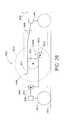
- FIGS. 17, 18 and 19illustrate an embodiment of a rear caster suspension 1700 with a rear caster position sensing arrangement 1706 .
- the rear caster suspension 1700includes a pair of rear caster assemblies 1702 a , 1702 b , a pair of sensors or triggers 1704 a , 1704 b , the rear caster position sensing arrangement 1706 , and a pair of biasing members 1708 a , 1708 b , such as springs or other resilient members.
- the rear caster position sensing arrangement 1706is in communication with both rear caster assemblies 1702 a , 1702 b .
- the rear caster position sensing arrangementcommunicates this condition to both sensors or triggers 1704 a , 1704 b .
- the rear castor position sensing arrangementcommunicates this condition to both sensors or triggers 104 a and 104 b .
- both sensors or triggers 1704 a , 1704 bare placed in an engaged state when both rear casters 1702 a , 1702 b fall below their normal operating positions and both sensors or triggers 1704 a , 1704 b are placed in a disengaged state when one or both of the rear casters are in a normal operating position.
- the conditions of the rear casterscan be communicated by the rear caster position sensing arrangement in a wide variety of different ways.
- the rear caster position sensing arrangementmay be a mechanical linkage or assembly that communicates the condition of the rear casters to the sensors, as illustrated by FIGS. 17A-17C .
- Each rear caster assembly 1702includes a caster 1710 and a pivot arm 1712 .
- the castor 1710is rotatable about an axis 1714 with respect to the pivot arm 1712 .
- the pivot arms 1712are coupled to a wheelchair frame 1701 (See FIG. 17B ) at pivots 1716 a , 1716 b .
- the sensors or triggers 1704 a , 1704 bare supported by the wheelchair frame 1701 .
- the illustrated rear caster position sensing arrangement 1706includes a pair of spaced apart trigger actuating members 1720 a , 1720 b that are coupled to the wheelchair frame 1701 at pivots 1722 a , 1722 b .
- the trigger actuating members 1720 a , 1720 bare connected together by a bar 1724 .
- the biasing members 1708 a , 1708 bare interposed between the rear caster assemblies 1702 a , 1702 b and the trigger actuating members 1720 a , 1720 b.
- the rear caster suspension 1700 and rear caster position sensing arrangement 1706can be included on any type of wheelchair to sense a tipping behavior and control one or more stabilizing members or a stabilizing assembly to inhibit further tipping. Referring to FIGS. 17A, 17B and 17C , when the rear caster assemblies 1702 a , 1702 b are in normal operating positions relative to the frame, 1701 , the biasing members 1708 a , 1708 b are compressed between the trigger actuating members 1720 a , 1720 b and the rear caster pivot arms 1712 a , 1712 b .
- the biasing members 1708 a , 1708 bforce the trigger actuating members 1708 a , 1708 b into engagement with the sensors or triggers 1704 a , 1704 b to place both of the sensors in a depressed or disengaged state.
- FIGS. 18A and 18Billustrate the rear caster suspension 1700 and rear caster position sensing arrangement 1706 where the rear caster assembly 1702 b is in a normal operating position and the rear caster assembly 1702 a has dropped below the range of normal operating positions.
- This conditionmay occur when the wheelchair travels laterally along an inclined surface 1800 .
- This conditionmay also occur when one of the rear casters falls into a depression (see FIGS. 3A, 3B, and 3C ).
- the biasing member 1708 bWhen the rear caster assembly 1702 b is in a normal operating position and the rear caster assembly 1702 a has dropped below the range of normal operating positions, the biasing member 1708 b remains compressed between the trigger actuating member 1720 b and the rear caster pivot arms 1712 b , while the biasing member 1708 a extends to a relaxed state (See FIG. 18B ).
- the biasing member 1708 bforces the trigger actuating member 1720 b into engagement with the sensor or trigger 1704 b .
- the bar 1724 that connects the trigger actuating member 1720 a to the trigger actuating member 1720 bholds the trigger actuating member 1720 a in engagement with the sensor or trigger 1704 a .
- the trigger actuating members 1720 a , 1720 bplace both of the sensors in a depressed or disengaged state when the rear casters are in the positions shown in FIGS. 18A and 18B .
- FIGS. 19A and 19Billustrate the rear caster suspension 1700 and rear caster position sensing arrangement 1706 where the rear caster assemblies 1702 a , 1702 have both dropped below the range of normal operating positions. This condition may occur when the wheelchair exhibits a tipping behavior.
- the biasing members 1708 a , 1708 bboth extend to a relaxed state and may pull the trigger actuating members 1708 a , 1708 b out of engagement with the sensors or triggers 1704 a , 1704 b to place the sensors or triggers in an engaged state.
- both sensors or triggersare returned to the disengaged state.
- FIGS. 20, 21 and 22illustrate an embodiment of a rear caster suspension 2000 and rear caster position sensing arrangement 2006 where movement of one caster assembly 2002 a is limited, depending on the position of the second caster assembly 2002 b .
- the rear caster suspensionincludes a pair of rear caster assemblies 2002 a , 2002 b , a pair of sensors or triggers 2004 a , 2004 b , the rear caster position sensing arrangement 2006 , and a pair of biasing members 2008 a , 2008 b , such as springs or other resilient members.
- compression springsare schematically represented. However, extension springs can be used, or the biasing members can take some other form.
- Each rear caster assembly 2002includes a caster 2010 , a pivot arm 2012 a , 2012 b , and a stop member 2013 a , 2013 b attached to the pivot arm.
- the pivot arms 2012are coupled to a wheelchair frame 2001 at pivots 2016 a , 2016 b (See FIG. 20B ).
- the stop members 2013 a , 2013 brotate with the pivot arms 2012 a , 2012 b about the pivots 2016 a , 2016 b .
- the sensors or triggers 2004 a , 2004 bare supported by the wheelchair frame 2001 .
- the illustrated rear caster position sensing arrangement 2006includes a pair of spaced apart trigger actuating members 2020 a , 2020 b that are coupled to the wheelchair frame 2001 at pivots 2022 a , 2022 b .
- the elongated members 2020 a , 2020 bare connected together by a bar 2024 .
- the bar 2024extends past the pivots 2022 a , 2022 b for selective engagement with the stop members 2013 a , 2013 b .
- the biasing members 2008 a , 2008 bare interposed between the rear caster assemblies 2002 a , 2002 b and the trigger actuating members 2020 a , 2020 b.
- the rear caster suspension 2000 and rear caster position sensing arrangement 2006operate to place the sensors in the disengaged and engaged states based on the positions of the rear caster assemblies 2002 a , 2002 b .
- the rear caster suspension 2000 and rear caster position sensing arrangement 2006limit the relative positions of the rear caster assemblies 2002 a , 2002 b .
- the suspension arrangement 2000does not include a rear caster position sensing arrangement, and the sensors 2004 a , 2004 b are omitted.
- the elongated members 2020 a , 2020 bmay be modified accordingly or replaced with a different arrangement for coupling the biasing members 2008 a , 2008 b to the bar 2024 .
- the biasing members 2008 a , 2008 bhold the trigger actuating members 2020 a , 2020 b against the sensors or triggers 2004 a , 2004 b (or some other stop if the sensors are omitted).
- the trigger actuating members 2020 a , 2020 bposition the bar 2024 with respect to the stop members 2013 .
- the position of the bar 2024is fixed.
- the caster assemblies 2002are free to move upwardly and downwardly with respect to one another.
- FIGS. 21A and 21Billustrate the situation where the rear caster assembly 2002 b drops, such that the stop member 2013 b rotates into contact with the bar 2024 .
- the stop member 2013 bengages the bar 2024
- further movement of the rear caster assembly 2002 bis inhibited by the bar.
- the bar 2024prevents the caster assembly 2002 a from falling into a deep depression.
- the rear caster assembly 2002 acan be moved downward by applying a downward force indicated by arrow 2050 in FIGS. 22A and 22B .
- the forceis applied by the stop member 2013 b , to the bar 2024 , and to the trigger actuating member 2020 b .
- the trigger actuating member 2020 bmoves toward the rear caster pivot arm 2012 b .
- the elongated members 2020 a , 2020 bmay move away from the triggers or sensors 2004 a , 2004 b .
- the sensors 2004 a , 2004 bare placed in the engaged state in the same manner as described with respect to the rear caster suspension and trigger arrangement 1700 .
- the sensors 2004 a , 2004 bare placed in a disengaged state in the same manner as described with respect to the rear caster suspension and trigger arrangement 1700 .
- FIGS. 23 and 24illustrate another embodiment of a rear caster suspension 2300 with a rear caster position sensing arrangement 2306 .
- the rear caster suspensionincludes a rear caster assembly 2302 , a pair of sensors or triggers 2304 a , 2304 b , the rear caster position sensing arrangement 2306 , and a biasing member 2308 , such as a spring.
- a compression springis schematically represented.
- an extension springcan be used, or the biasing member can take some other form.
- the rear caster assembly 2302includes a pair of casters 2310 a , 2310 b and a pivot arm 2312 .
- the pivot arm 2312includes a first member 2313 coupled to a wheelchair frame 2301 at a pivot 2316 (See FIG. 23B ) and a second member 2315 connected to the first member 2313 , such that the pivot arm 2312 has a generally “T-shaped” configuration.
- the castors 2310 a , 2310 bare connected to ends of the second member 2315 and are rotatable with respect to the pivot arm 2312 .
- the sensors or triggers 2304 a , 2304 bare supported by the wheelchair frame 2301 .
- the illustrated rear caster position sensing arrangement 2306includes a pair of spaced apart elongated members 2319 a , 2319 b (See FIG. 23A ) that support a trigger actuating member 2320 and are coupled to the wheelchair frame 2301 at pivots 2322 a , 2322 b .
- the rear caster position sensing arrangement 2306could also be configured to include only one member (or any other number of members) member that supports the rear caster position sensing arrangement 2306 .
- the biasing member 2308is interposed between the rear caster assembly 2302 and the trigger actuating member 2320 .
- the rear caster suspension 2300 with the rear caster position sensing arrangement 2306can be included on any type of wheelchair to sense a tipping behavior and control one or more stabilizing members or stabilizing assemblies.
- the biasing member 2308when the rear caster assembly 2302 is in a normal operating position relative to the frame 2301 , the biasing member 2308 is compressed between the trigger actuating member 2320 and the rear caster pivot arm 2312 .
- the biasing members 2308force the trigger actuating member 2308 into engagement with both of the sensors or triggers 2304 a , 2304 b to place both of the sensors in a depressed or disengaged state.
- FIGS. 24A, 24B and 24Cillustrate the rear caster suspension 2300 and the rear caster position sensing arrangement 2306 where one of the rear casters 2310 a of the rear caster assembly 2302 a encounters a depression in the support surface. Since both rear casters 2310 a , 2310 b are coupled to a common pivot arm, the rear caster 2310 a does not drop into the depression.
- the biasing member 2308remains compressed between the trigger actuating member 2320 and the rear caster pivot arms 2312 a .
- the biasing member 2308forces the trigger actuating member 1708 into engagement with the sensors or triggers 2304 a , 2304 b .
- the biasing member 2308When the rear caster assembly 2302 drops below the range of normal operating positions, the biasing member 2308 extends to a relaxed state and may pull the trigger actuating member 2308 out of engagement with the sensors or triggers 1704 a , 1704 b to place the sensors or triggers in an engaged state.
- FIGS. 25A, 25B and 25Cillustrate a rear caster suspension 2500 that is a variation of the rear caster suspension 2300 where the second member 2315 of the pivot arm is pivotally connected to the first member 2313 by a pivotal connection 2500 .
- the pivotal connectionallows the ends of the second member 2315 and the attached rear casters 2310 a , 2310 b to move upward and downward with respect to one another. When one rear caster 2310 a moves down, the other rear caster 2310 b moves up.
- Stability systemscan be used on a wide variety of vehicles.
- the wheelchairsmay include front caster pivot arms of any configuration.
- the front caster pivot armsmay be coupled to drive assemblies or the front caster pivot arms may be independent of the drive assemblies (See FIGS. 1A, 1B, 1C ).
- the front caster pivot armscan be coupled to the drive assemblies in a wide variety of different ways.
- the front caster pivot armscan be coupled to the drive assembly in any manner that transfers motion of the drive assembly to the front caster pivot arm, including but not limited to, a fixed length link, a variable length link, a flexible link, a chain, a cord, a belt, a wire, a gear train, or any other known structure for transferring motion from one structure to another structure.
- FIGS. 26-31illustrate one side of wheelchairs with stability systems and pivot arms that are coupled to a drive assembly. The other side is a mirror image in the exemplary embodiment and is therefore not described in detail.
- FIG. 26schematically illustrates a mid-wheel drive wheelchair 2600 that includes a tip or stability control system that comprises at least one tip sensor or trigger 2612 and at least one stabilizing member or assembly 2614 .
- the wheelchair 2600includes front caster pivot arms 2608 that are coupled to drive assemblies 2606 .
- Each drive assembly 2606includes a drive wheel 2615 and a motor or drive 2617 that propels the drive wheel 2615 .
- the drive 2617may comprise a motor/gear box combination, a brushless, gearless motor, or any other known arrangement for driving the drive wheel 2615 .
- the drive assembly 2606is connected to the frame 2602 at a pivotal connection 2619 . In the example illustrated by FIG. 26 , the pivotal connection 2619 is disposed below a drive axis 2621 of the drive wheel 2615 when the wheelchair 2600 is resting on flat, level ground.
- a front caster pivot arm 2608is connected to each drive assembly 2606 .
- a front caster 2631is coupled to each front caster pivot arm 2608 .
- the front caster 2631is movable upwardly and downwardly as indicated by double arrow 2616 by pivotal movement of the drive 2617 about the pivotal connection 2619 .
- Torque applied by the drive assembly 2606urges the front caster pivot arm 2608 and the front caster 2631 upward with respect to a support surface 2633 as indicated by arrow 2635 .
- the torque applied by the drive assembly 2606lifts the front caster 2631 off the support surface 2633 .
- the torque applied by the drive assembly 2606urges the front caster 2631 upward, but does not lift the front caster up off of the support surface.
- Rear casters 2610are coupled to the frame 2602 such that the rear casters are moveable upwardly and downwardly with respect to the frame.
- a stabilizing assembly 2614is coupled to each front caster pivot arm 2618 and to the frame 2602 .
- the stabilizing assemblycan take any form that allows the stabilizing assembly to inhibit tipping behavior.
- One or more triggers or sensors 2612may be coupled to rear caster pivot arms 2620 to detect a tipping behavior of the wheelchair.
- a trigger or sensorcan be arranged in any manner to detect a tipping behavior of the wheelchair and need not be coupled to a rear caster.
- the trigger or sensor 2612senses when conditions exist that may cause the vehicle to exhibit a tipping behavior and causes the locking assembly 2614 to engage when a tipping behavior is sensed to prevent any further tipping behavior.
- FIG. 27schematically illustrates a mid-wheel drive wheelchair 2700 that includes a tip or stability control system that comprises at least one tip sensor or trigger 2712 and at least one stabilizing member or assembly.
- the wheelchair 2700is similar to the wheelchair 2600 of FIG. 26 , but each front caster pivot arm 2708 includes upper and lower links 2710 a , 2710 b that define a four bar linkage.
- the upper link 2710 ais pivotally coupled to a caster support member 2711 at a pivotal connection 2780 and is fixedly connected to the drive 2617 .
- the lower link 2710 bis pivotally coupled to the caster support member 2711 at a pivotal connection 2782 and is pivotally connected to the frame 2701 at a pivotal connection 2783 .
- the drive 2617 , the links 2710 a , 2710 b , the frame 2701 , and the caster support member 2711form a four-bar linkage.
- the pivotal connections 2619 , 2780 , 2782 , 2783can be positioned at a wide variety of different locations on the frame 2701 and the caster support member 2711 and the length of the links 2706 can be selected to define the motion of the front caster as the front caster pivot arm 2708 is pivoted.
- the rear casters 2710are coupled to the frame 2701 such that the rear casters are moveable upwardly and downwardly with respect to the frame.
- a stabilizing assembly 2714is coupled to each front caster pivot arm 2718 and to the frame 2702 .
- the stabilizing assemblycan take any form and be coupled in any manner that allows the stabilizing assembly to inhibit tipping behavior.
- a stabilizing assembly 2714can be coupled to the drive 2617 .
- One or more triggers or sensors 2712are coupled to the rear caster pivot arms 2720 to detect a tipping behavior of the wheelchair.
- a trigger or sensorcan be arranged in any manner to detect a tipping behavior of the wheelchair and need not be coupled to a rear caster.
- the trigger or sensor 2712senses when conditions exist that may cause the vehicle to exhibit a tipping behavior and causes the locking assembly 2714 to engage when a tipping behavior is sensed to prevent any further tipping behavior.
- FIG. 28schematically illustrates a mid-wheel drive wheelchair 2800 that includes a tip or stability control system 2802 that comprises at least one tip sensor or trigger 2812 and at least one stabilizing member or assembly.
- Front caster pivot arms 2808are coupled to drive assemblies 2806 by a link 2809 .
- the wheelchair 2800is similar to the wheelchair 2600 of FIG. 26 , but the front caster pivot arm 2808 is pivotally coupled to the frame 2801 and is coupled to the drive assembly 2806 by the link 2809 .
- Each drive assembly 2806is mounted to the frame 2801 by a pivot arm 2820 at a drive assembly pivot axis 2822 .
- the pivot arm 2820extends forward and downward from the motor drive to the drive assembly pivot axis 2822 .
- the pivot axis 2822 of the drive assembly pivot arm 2820is below the drive wheel axis of rotation 2830 and the axis 2832 of an axle 2834 that the front caster wheel 2836 rotates around.
- a biasing membersuch as a spring may optionally be coupled between the frame 2801 and the front caster pivot arm 2808 and/or the frame and the drive assembly 2806 to bias the front caster into engagement with the support surface 2819 or a biasing member may be included in the stabilizing assembly 2814 .
- the front caster pivot arm 2808is pivotally mounted to the frame at a pivot axis 2850 .
- the pivot axis 2850 of the front caster pivot arm 2808is forward of the drive assembly pivot axis 2822 and below the axis of rotation 2830 of the drive wheel.
- the link 2809is connected to the drive assembly pivot arm 2820 at a pivotal connection 2851 and is connected to the front caster pivot arm 2808 at a pivotal connection 2852 .
- the link 2809can take a wide variety of different forms.
- the linkmay be rigid, flexible, or extendible in length.
- the linkneed not comprise a linear member for example, the link may be a gear train.
- the link 2809may be any mechanical arrangement that transfers at least some portion of motion in at least one direction of the drive assembly 2806 to the front caster pivot arm 2808 .
- the drive assembly 2806pivots and pulls the link 2809 .
- Pulling on the link 2809causes the front caster pivot arm 2808 to move upward or urges the pivot arm upward.
- the link 2809is a variable length link, such as a spring, a shock absorber, or a shock absorber with a spring return
- the drive assembly 2806pulls the link 2809 to extend the link to its maximum length or a length where the front caster pivot arm 2808 begins to pivot. Once extended, the link 2809 pulls the front caster pivot arm 2808 upward or urges the front caster pivot arm upward.
- Rear casters 2810are coupled to the frame 2801 such that the rear casters are moveable upwardly and downwardly with respect to the frame.
- a stabilizing assembly 2814is coupled to each front caster pivot arm 2808 and to the frame 2801 , to the drive assembly 2806 and the frame 2801 and/or to the link 2809 and the frame 2801 .
- the stabilizing assemblycan take any form and be positioned in any manner that allows the stabilizing assembly to inhibit a tipping behavior.
- One or more triggers or sensors 2812are coupled to the rear caster pivot arms 2820 to detect a tipping behavior of the wheelchair.
- a trigger or sensorcan take any form and be arranged in any manner to detect a tipping behavior of the wheelchair and need not be coupled to a rear caster.
- the trigger or sensor 2812senses when conditions exist that may cause the vehicle to exhibit a tipping behavior and causes the locking assembly 2814 to engage when a tipping behavior is sensed to prevent any further tipping behavior.
- FIG. 29schematically illustrates a mid-wheel drive wheelchair 2900 that includes a tip or stability control system that comprises at least one tip sensor or trigger 2912 and at least one stabilizing member or assembly 2914 .
- Front caster pivot arms 2908are coupled to drive assemblies 2906 by a link 2909 .
- the wheelchair 2900is similar to the wheelchair 2800 of FIG. 28 , but the front caster pivot arm 2908 and the drive assembly pivot arm 2920 are disposed in a crossed configuration.
- Each drive assembly 2906is mounted to a frame 2901 by a pivot arm 2920 at a drive assembly pivot axis 2922 .
- the pivot arm 2920extends forward and downward from the motor drive to the drive assembly pivot axis 2922 .
- the pivot axis 2922 of the drive assembly pivot arm 2920is below the drive wheel axis of rotation 2930 .
- the front caster pivot arm 2908is pivotally mounted to the frame at a pivot axis 2949 .
- the pivot axis 2949 of the front caster pivot arm 2908is rearward of the drive assembly pivot axis 2932 and below the axis of rotation 2930 of the drive wheel.
- the front caster pivot arm 2908 and the drive assembly pivot arm 2920are in a crossed configuration.
- the front caster pivot arm 2908 and the drive assembly pivot arm 2920may be bent or may be offset to accommodate the crossed configuration.
- the link 2909is connected to the drive assembly pivot arm 2920 at a pivotal connection 2950 and is connected to the front caster pivot arm 2908 at a pivotal connection 2952 .
- the link 2909can take a wide variety of different forms. Any link 2909 that transfers at least some portion of motion in at least one direction of the drive assembly 2906 to the front caster pivot arm 2908 can be used.
- Rear casters 2910are coupled to the frame 2901 such that the rear casters are moveable upwardly and downwardly with respect to the frame.
- a stabilizing assembly 2914is coupled to each front caster pivot arm 2908 and to the frame 2901 , to the drive assembly 2906 and the frame 2901 and/or to the link 2909 and the frame 2901 .
- One or more triggers or sensors 2912are coupled to rear caster pivot arms 2920 to detect a tipping behavior of the wheelchair.
- a trigger or sensorcan take any form and be arranged in any manner to detect a tipping behavior of the wheelchair and need not be coupled to a rear caster.
- the trigger or sensor 2912senses when conditions exist that may cause the vehicle to exhibit a tipping behavior and causes the locking assembly 2914 to engage when a tipping behavior is sensed to prevent any further tipping behavior.
- FIG. 30schematically illustrates a mid-wheel drive wheelchair 3000 that includes a tip or stability control system that comprises at least one tip sensor or trigger 3012 and at least one stabilizing member or assembly 2914 .
- Front caster pivot arms 3008are coupled to drive assemblies 3006 by a link 3009 .
- the wheelchair 3000is similar to the wheelchair 2900 of FIG. 29 , but the front caster pivot arm 3008 comprises an upper link 3011 a and a lower link 3011 b.
- the upper link 3011 ais pivotally coupled to a caster support member 3013 at a pivotal connection 3015 and is pivotally connected to the frame 3001 at a pivotal connection 3017 .
- the lower link 3011 bis pivotally coupled to the caster support member 3013 at a pivotal connection 3019 and is pivotally connected to the frame 3001 at a pivotal connection 3021 .
- the caster support member 3013may be any structure that couples the links 3011 a , 3011 b to be coupled to a front caster 3036 .
- the links 3011 a , 3011 b , the frame 3001 , and the caster support member 3013form a four-bar linkage.
- the pivotal connections 3015 , 3017 , 3019 , 3021can be positioned at a wide variety of different locations on the frame 3001 and the caster support member 3013 and the length of the links 3011 a , 3011 b can be selected to define the motion of the caster 3036 as the front caster pivot arm 3008 is pivoted. In the example illustrated by FIG.
- the front caster pivot arm 3008retracts the front caster 3008 or pivots the wheel of the front caster toward the frame as the pivot arm 3008 is lifted and extends the front caster or pivots the wheel of the front caster away from the frame as the front caster pivot arm is lowered.
- Each drive assembly 3006is mounted to the frame 3001 by a pivot arm 3020 at a drive assembly pivot axis 3022 .
- the pivot arm 3020extends forward and downward from the motor drive to the drive assembly pivot axis 3022 .
- the pivot axis 3022 of the drive assembly pivot arm 3020is below the drive wheel axis of rotation 3030 and is in front of the front caster pivot arms 3008 .
- the front caster pivot arm 3008 and the drive assembly pivot arm 3020are in a crossed configuration.
- the front caster pivot arm 3008 and the drive assembly pivot arm 3020may be bent or may be offset to accommodate the crossed configuration.
- the link 3009is connected to the drive assembly pivot arm 3020 at a pivotal connection 3050 and is connected to the front caster pivot arm 3008 at a pivotal connection 3052 .
- the link 3009can be connected to the upper link 3011 a , or the lower link 3011 b . Any link 3009 that transfers at least some portion of motion in at least one direction of the drive assembly 3006 to the front caster pivot arm 3008 can be used.
- the drive assembly 3006may pivot and pull the link 3909 . Pulling on the link 3009 causes the front caster pivot arm 3008 to move upward or urges the pivot arm upward.
- Rear casters 3010are coupled to the frame 3001 such that the rear casters are moveable upwardly and downwardly with respect to the frame.
- a stabilizing assembly 3014is coupled to each front caster pivot arm 3008 and to the frame 3001 , to the drive assembly 3006 and the frame 3001 and/or to the link 3009 and the frame 3001 .
- One or more triggers or sensors 3012are coupled to rear caster pivot arms 3020 to detect a tipping behavior of the wheelchair.
- a trigger or sensorcan take any form and can be arranged in any manner to detect a tipping behavior of the wheelchair and need not be coupled to a rear caster.
- the trigger or sensor 3012senses when conditions exist that may cause the vehicle to exhibit a tipping behavior and causes the locking assembly 3014 to engage when a tipping behavior is sensed to inhibit further tipping behavior.
- FIG. 31schematically illustrates a mid-wheel drive wheelchair 3100 that includes a tip or stability control system that comprises at least one tip sensor or trigger 3112 and at least one stabilizing or assembly 3114 .
- Front caster pivot arms 3108are coupled to drive assemblies 3106 by a link 3109 .
- the wheelchair 3100is similar to the wheelchair 2800 of FIG. 28 , but the front caster pivot arm 3108 and the drive assembly 3106 are pivotally coupled to the frame 3101 at a common pivot axis 3122 .
- Each drive assembly 3106is mounted to the frame 3101 by a pivot arm 3120 .
- the pivot arm 3120extends forward and downward from the motor drive to the common pivot axis 3122 .
- the pivot axis 3122is below the drive wheel axis of rotation 3130 and the axis 3132 that the front caster wheel 3136 rotates around.
- the link 3109is connected to the drive assembly pivot arm 3120 at a pivotal connection 3150 and is connected to the front caster pivot arm 3108 at a pivotal connection 3152 .
- the link 3109can take a wide variety of different forms.
- the linkmay be rigid, flexible, or extendible in length. Any link 3109 that transfers at least some portion of motion in at least one direction of the drive assembly 3106 to the front caster pivot arm 3108 can be used.
- the drive assembly 3106When the drive assembly 3106 is accelerated, the drive assembly 3106 may pivot and pull on the link 3109 . Pulling on the link 3109 causes the front caster pivot arm 3108 to move upward or urges the pivot arm upward.
- Rear casters 3110are coupled to the frame 3101 such that the rear casters are moveable upwardly and downwardly with respect to the frame.
- a stabilizing assembly 3114is coupled to each front caster pivot arm 3108 and to the frame 3101 , to the drive assembly 3106 and the frame 3101 and/or to the link 3109 and the frame 3101 .
- the stabilizing assemblycan take any form and be positioned in any manner that allows the stabilizing assembly to inhibit tipping behavior.
- One or more triggers or sensors 3112are coupled to the rear caster pivot arms 3110 to detect a tipping behavior of the wheelchair.
- a trigger or sensorcan take any form and be arranged in any manner to detect a tipping behavior of the wheelchair and need not be coupled to a rear caster.
- the trigger or sensor 3112senses when conditions exist that may cause the vehicle to exhibit a tipping behavior and causes the locking assembly 3114 to engage when a tipping behavior is sensed to prevent any further tipping behavior.
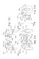
- FIGS. 32-37illustrate an example of a mid-wheel drive wheelchair 3200 that includes a control system that comprises sensors or triggers 3212 a , 3212 b and stabilizing members 3214 a , 3214 b .
- the wheelchair 3200includes a frame 3202 , a seat (not shown) is supported by the frame 3202 , first and second drive assemblies 3206 a , 3206 b , first and second front caster pivot arms 3218 a , 3218 b , first and second front casters 3208 a , 3208 b , first and second rear caster pivot arms 3220 a , 3220 b , and first and second rear casters 3210 a , 3210 b .
- a rear caster position sensing arrangement 4400(see FIGS. 44-51 ) communicates a condition of the rear caster pivot arms 3220 a , 3220 b to both of the sensors or triggers 3212 a , 3212 b.
- the illustrated frame 3202is made from sheetmetal panels, but can be constructed in any manner that is suitable for the application of the wheelchair 3200 .
- the illustrated frame 3202defines an interior space 3203 for batteries (not shown), wiring (not shown), and other wheelchair components.
- each drive assembly 3206 a , 3206 bincludes a drive wheel 3215 and a motor or drive 3217 that propels the drive wheel 3215 .
- the drive 3217may comprise a motor/gear box combination, a brushless, gearless motor, or any other known arrangement for driving the drive wheel 3215 .
- the drive 3717is coupled to the frame 3202 at a pivotal connection 3219 .
- the pivotal connection 3219is disposed below a drive axis 3221 of the drive wheel 3215 when the wheelchair 3200 is resting on flat, level ground.
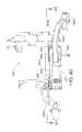
- FIG. 38-41show the wheelchair 3200 with many of the components removed to more clearly illustrate the drive 3217 , the front pivot caster pivot arm 3218 a , the rear caster pivot arm 3220 a , and the stabilizing member 3214 a mounted on one side of the frame 3202 .
- the component mounting on the other side of the frame 3202may be a mirror image, and is therefore not described in detail.
- each front caster pivot arm 3218 a , 3218 bincludes upper and lower links 3223 a , 3223 b that define a four bar linkage.
- the upper link 3223 ais pivotally coupled to a caster support member 3211 at a pivotal connection 3280 and is fixedly connected to the drive 3217 .
- the lower link 3223 bis pivotally coupled to the caster support member 3211 at a pivotal connection 3282 and is pivotally connected to the frame 3202 at a pivotal connection 3283 .
- the drive 3217 , the links 3223 a , 3223 b , the frame 3202 , and the caster support member 3211form a four-bar linkage.
- the front caster 3208 ais coupled to the caster support member 3211 .
- the front caster pivot arms 3218 a , 3218 bare independently pivotable upwardly and downwardly on the opposite sides of the frame to move the front casters 3208 a , 3208 b upwardly and downwardly with respect to the frame 3202 .
- the drive assembly 3206 awhen the drive assembly 3206 a is accelerated such that the moment arm generated by drive wheel 3215 is greater then all other moment arms around pivot axis 3219 , the drive assembly 3206 pivots about pivot axis 3219 to move the front caster pivot arm 3218 upward or urges the pivot arm upward as indicated by arrow 3301 . Resulting upward tendencies of the front caster 3208 a helps the wheelchair 3200 to traverse obstacles.
- the drive assembly 3206 boperates in the same manner or a similar manner to move or urge the front caster 3208 b upward.
- the stabilizing member 3214 acomprises a hydraulic cylinder with a spring return (see also FIGS. 5 and 6 ).
- the stabilizing member 3214 aincludes a housing 4004 , and a rod 4008 .
- the sensor or trigger 3212 ais a portion of a button 4006 that extends from the stabilizing member 3214 a .
- the position of the button 4006determines the state of the stabilizing member 3214 a .
- the rod 4008may move into and out of the housing 4004 to extend and shorten the length of the stabilizing member 3214 a .
- the rod 4008When the button 4006 is extended, the rod 4008 may move out of the housing 4004 to extend the length of the stabilizing member 3214 a , but is prevented from moving into the housing 4004 to shorten the length of the stabilizing member.
- the button 4006When the button 4006 is in the depressed position, the movement of the fluid in the stabilizing member 3214 a when the rod extends and retracts provides a damping effect.
- the stabilizing memberdamps downward movement of the front caster.
- a spring returnbiases or returns the rod 4008 to an extended position to bias the front caster toward contact with the ground.
- the stabilizing member 3214 ais pivotally connected to the frame 3202 at a pivotal connection 4020 and to the drive assembly/front caster pivot arm at a pivotal connection 4022 .
- the stabilizing member 3214 acan extend to allow the front caster to move downward with respect to the frame 3202 , but cannot retract to prevent upward movement of the front caster with respect to the frame.
- the stabilizing member 3214 aallows the front caster to move upward and downward with respect to the frame.
- the pivotal connection 4020may comprise a ball 4030 and socket 4032 connection.
- the ball 4030is mounted to the rod 4008 .
- the socket 4032is connected to the frame 3202 . If the pivotal connection 4020 is made before the pivotal connection 4022 , the ball 4030 can be turned in the socket 4032 to facilitate alignment required to make the pivotal connection 4022 . If the pivotal connection 4022 is made before the connection 4022 , the ball 4030 can be assembled in the socket 4022 , regardless of the orientation of the ball with respect to the socket. As a result, assembly of the stabilizing members 3214 a , 3214 b to the frame and to the drive assembly/front caster pivot arm is made easier.
- vibration damping assemblies 4250are coupled to the button 4006 of each stabilizing member 3214 a , 3214 b to prevent vibration of the button 4006 in the rod 4008 .
- FIG. 42illustrates a vibration damping assembly 4250 that includes a ball portion for a ball and socket connection.
- FIG. 43illustrates a vibration damping assembly 4250 where the ball is omitted and the stabilizing member 3214 a is connected to the frame by a conventional pivotal coupling or the ball is coupled to the stabilizing member at another location.
- the vibration dampingincludes a housing 4212 , a trigger extension member 4214 , and a biasing member 4216 , such as a spring or other resilient member.
- the housing 4212is disposed on the end of the rod 4008 .
- the ball 4030is defined as part of the housing 4212 .
- the housing 4212does not include a ball portion.
- the trigger extension member 4214is disposed in the housing 4212 in engagement with the control rod 4210 .
- the biasing member 4216biases the trigger extension member 4214 against the button 4006 .
- the biasing member 4216applies a preload to the button 4006 to inhibit vibration of the button 4006 in the rod 4008 .
- the force applied by the biasing member 4216is small enough that the biasing member 4216 does not depress the control rod 4210 to a point where the stabilizing member 3214 a , 3214 changes state (i.e. from an engaged state to a disengaged state).
- each rear caster pivot arm 3220 a , 3220 bis independently coupled to the frame 3202 at a pivotal connection 3602 a , 3602 b .
- Each rear caster 3210 a , 3210 bis coupled to a rear caster pivot arm 3220 a , 3220 b , such that each rear caster can rotate around a substantially vertical axis.
- FIGS. 44-50illustrates the rear caster position sensing arrangement 4400 and a rear caster suspension 4402 of the wheelchair 3200 .
- the rear caster suspension 4402includes the rear caster pivot arms 3220 a , 3220 b , the rear casters 3210 a , 3210 b , and biasing members 4408 a , 4408 b , such as a spring or other resilient member.
- a stop member 4413 a , 4413 bis attached to each pivot arm.
- the stop members 4413 a , 4413 brotate with the pivot arms 3220 a , 3220 b .
- the rear caster position sensing arrangement 4400includes a pair of spaced apart trigger engagement assemblies 4420 a , 4420 b that are coupled to the wheelchair frame at pivotal connections 4422 a , 4422 b .
- each rear caster position sensing arrangementincludes an elongated member 4423 pivotally coupled to the frame, and an adjustable trigger engagement member 4425 connected to the elongated member 4423 .
- the adjustment between the engagement member 4425 and the elongated member 4423allows the amount of rotation of the rear caster position sensing arrangement that causes engagement of the stabilizing members to be adjusted.
- the distance that the engagement members 4325 extend from the elongated members 4323is adjustable.
- the distance that the engagement members 4325 extend from the elongated membersdetermines the amount of rotation of the rear caster position sensing arrangement that is required to cause the stabilizing assemblies to engage and disengage.
- the trigger engagement assemblies 4420 a , 4420 bare replaced with the single piece trigger engagement members.
- the pivotal connections 4422 a , 4422 bare coaxial with pivotal connections 3602 a , 3602 b of the rear caster pivot arms. In another embodiment, the pivotal connections 4422 a , 4422 b are offset form the pivotal connections 3602 a , 3602 b .
- the elongated members 4420 a , 4420 bare connected together by a bar 4424 . Referring to FIGS. 45 and 51 , the bar 4424 is disposed between first and second engagement surfaces 4430 , 4432 of the stop members 4413 a , 4413 b .
- the bar 4424selectively engages the stop members 4413 a , 4413 b to limit relative movement between the first and second rear caster pivot arms 3220 a , 3320 b .
- the biasing members 4408 a , 4408 bare interposed between the rear caster pivot arms 3220 a , 3220 b and the elongated members 4420 a , 4420 b.
- the rear caster position sensing arrangement 4400operates to cause both sensors or triggers to place both of the stabilizing members 3214 a , 3214 b in the engaged and disengaged states based on the positions of the rear caster pivot arms 3320 a , 3320 b .
- FIG. 49illustrates rear caster pivot arm 3320 a in a normal operating position. Rear caster pivot arm 3320 b is not visible in FIG. 49 , because it is in the same, normal operating position, as rear caster pivot arm 3320 a . When (shown schematically in FIG.
- one or both of the rear caster pivot arms 3320 a , 3320 bare in normal operating positions relative to the frame 3202 , one or more of the biasing members 4408 a , 4408 b hold both of the trigger engagement assemblies 4420 a , 4420 b against both of the sensors or triggers 3212 a , 3212 b , such that both stabilizing members are disengaged.
- the elongated members 4420 a , 4420 bposition the bar 4424 with respect to the stop members 4413 a , 4413 b .
- the position of the bar 4424is fixed.
- the rear caster pivot arms 3320 a , 3320 bare free to move upwardly and downwardly with respect to one another.
- the stop members 4413 a , 4413 bare in contact with the bar 24 .
- the stop members 4413 a , 4413 bengage the bar 4424 .
- the bar 4424is in engagement with the engagement surface 4430 of both of the stop members.
- downward movement of only one pivot arm 3320 a , 3320 bis inhibited by the bar 4024 and the biasing member 4408 a or 4408 b of the other pivot arm.
- both pivot arms 3320 a , 3320 bcan pivot downward together relative to the frame.
- downward movement indicated by arrow 4902 of both pivot arms 3220 a( 3220 b is hidden) allows the rear caster position sensing arrangement 4400 to move away from both of the triggers 3212 a , 3212 b , allows the triggers to extend, and causes both of the locking members 3214 to disengage.
- the rear caster pivot arms 3320 a , 3320 bmove independently from the position shown in FIG. 49 in the direction of arrow 4904 . Movement of each rear caster pivot arms 3320 a , 3320 b from the position shown in FIG. 49 in the direction indicated by arrow 4902 is dependent on the other rear caster pivot arm also moving in the direction indicated by arrow 4902 .
- each stabilizing member 3214 a( 3214 b not shown) is coupled to the frame 3202 and the front caster pivot arms 3218 a , 3218 b .
- the stabilizing members 3214 a( 3214 b not shown) allow upward and downward movement of the first and second front caster pivot arms 3218 a , 3218 b relative to the frame 3202 when first and second rear casters 3210 a , 3210 b are each in a normal position relative to the frame shown in FIG. 41 , because the rear caster position sensing arrangement 4400 engages both of the triggers 3212 a , 3212 b of the stabilizing members 3214 a , 3214 b in this position.
- the frame 3202 of the wheelchairis pitched slightly forward toward the front casters 3208 a , 3208 b .
- both of the rear casters 3320 a , 3320 bmove downward relative to the frame 3202 to maintain contact with the ground.
- This downward movementmoves the rear caster position sensing arrangement 4400 away from the triggers 3212 a , 3212 b , allows the triggers to move to the extended position and causes the stabilizing assemblies 3214 a , 3214 b to engage.
- the stabilizing assemblies 3214 a , 3214 bengage to lock the first and second front casters 3208 a , 3208 b against upward movement relative to the frame, but allow the front casters to move downward when engaged.
- the stabilizing assemblies 3214 a , 3214 bmay be configured in any manner that inhibits further tipping of the wheelchair frame when the stabilizing members are engaged.
- the stabilizing assemblies 3214 a , 3214 block the front caster pivot arms against both upward and downward movement with respect to the pivot arm when engaged.
- the triggersare depressed again to disengage and allow upward and downward movement of the front casters relative to the frame.
- the rear caster position sensing arrangementis configured such that movement of one of the rear casters to a normal operating position moves the other rear caster up as well.
- pivotal connectionscan be made of any number of structures including bearing assemblies, pins, nuts and bolts, and frictionless sleeve assemblies.
- springs or shock absorberscan be added between pivoting and non-pivoting components to limit, dampen, or somewhat resist the pivotal motions of these components.
- a brake-disc locking mechanismcould be integrated into any of the pivotal connections and serve as a stabilizing member or assembly that locks components coupled to the pivotal connection from rotation when actuated and freely allows pivotal motion about the connection when not actuated. Therefore, the invention, in its broader aspects, is not limited to the specific details, the representative apparatus, and illustrative examples shown and described. Accordingly, departures can be made from such details without departing from the spirit or scope of the applicant's general inventive concept.
Landscapes
- Health & Medical Sciences (AREA)
- Life Sciences & Earth Sciences (AREA)
- Animal Behavior & Ethology (AREA)
- General Health & Medical Sciences (AREA)
- Public Health (AREA)
- Veterinary Medicine (AREA)
- Engineering & Computer Science (AREA)
- Mechanical Engineering (AREA)
- Handcart (AREA)
- Vehicle Body Suspensions (AREA)
- Supply And Distribution Of Alternating Current (AREA)
- Radio Relay Systems (AREA)
- Sorption Type Refrigeration Machines (AREA)
- Invalid Beds And Related Equipment (AREA)
- Testing And Monitoring For Control Systems (AREA)
- Body Structure For Vehicles (AREA)
Abstract
Description
Claims (5)
Priority Applications (5)
| Application Number | Priority Date | Filing Date | Title |
|---|---|---|---|
| US15/146,260US9827823B2 (en) | 2007-02-14 | 2016-05-04 | Stability control system |
| US15/822,967US10532626B2 (en) | 2007-02-14 | 2017-11-27 | Stability control system |
| US16/740,785US11097589B2 (en) | 2007-02-14 | 2020-01-13 | Stability control system |
| US17/395,565US11535078B2 (en) | 2007-02-14 | 2021-08-06 | Stability control system |
| US17/979,107US11850906B2 (en) | 2007-02-14 | 2022-11-02 | Stability control system |
Applications Claiming Priority (5)
| Application Number | Priority Date | Filing Date | Title |
|---|---|---|---|
| US90151307P | 2007-02-14 | 2007-02-14 | |
| PCT/US2008/053242WO2008100759A2 (en) | 2007-02-14 | 2008-02-07 | Stability control system |
| US52447609A | 2009-07-24 | 2009-07-24 | |
| US14/566,899US9346335B2 (en) | 2007-02-14 | 2014-12-11 | Stability control system |
| US15/146,260US9827823B2 (en) | 2007-02-14 | 2016-05-04 | Stability control system |
Related Parent Applications (1)
| Application Number | Title | Priority Date | Filing Date |
|---|---|---|---|
| US14/566,899DivisionUS9346335B2 (en) | 2007-02-14 | 2014-12-11 | Stability control system |
Related Child Applications (1)
| Application Number | Title | Priority Date | Filing Date |
|---|---|---|---|
| US15/822,967ContinuationUS10532626B2 (en) | 2007-02-14 | 2017-11-27 | Stability control system |
Publications (2)
| Publication Number | Publication Date |
|---|---|
| US20160318367A1 US20160318367A1 (en) | 2016-11-03 |
| US9827823B2true US9827823B2 (en) | 2017-11-28 |
Family
ID=39493906
Family Applications (7)
| Application Number | Title | Priority Date | Filing Date |
|---|---|---|---|
| US12/524,476Active2031-08-21US8910975B2 (en) | 2007-02-14 | 2008-02-07 | Wheelchair with suspension |
| US14/566,899ActiveUS9346335B2 (en) | 2007-02-14 | 2014-12-11 | Stability control system |
| US15/146,260ActiveUS9827823B2 (en) | 2007-02-14 | 2016-05-04 | Stability control system |
| US15/822,967Active2028-03-10US10532626B2 (en) | 2007-02-14 | 2017-11-27 | Stability control system |
| US16/740,785ActiveUS11097589B2 (en) | 2007-02-14 | 2020-01-13 | Stability control system |
| US17/395,565ActiveUS11535078B2 (en) | 2007-02-14 | 2021-08-06 | Stability control system |
| US17/979,107ActiveUS11850906B2 (en) | 2007-02-14 | 2022-11-02 | Stability control system |
Family Applications Before (2)
| Application Number | Title | Priority Date | Filing Date |
|---|---|---|---|
| US12/524,476Active2031-08-21US8910975B2 (en) | 2007-02-14 | 2008-02-07 | Wheelchair with suspension |
| US14/566,899ActiveUS9346335B2 (en) | 2007-02-14 | 2014-12-11 | Stability control system |
Family Applications After (4)
| Application Number | Title | Priority Date | Filing Date |
|---|---|---|---|
| US15/822,967Active2028-03-10US10532626B2 (en) | 2007-02-14 | 2017-11-27 | Stability control system |
| US16/740,785ActiveUS11097589B2 (en) | 2007-02-14 | 2020-01-13 | Stability control system |
| US17/395,565ActiveUS11535078B2 (en) | 2007-02-14 | 2021-08-06 | Stability control system |
| US17/979,107ActiveUS11850906B2 (en) | 2007-02-14 | 2022-11-02 | Stability control system |
Country Status (7)
| Country | Link |
|---|---|
| US (7) | US8910975B2 (en) |
| EP (3) | EP2111204B1 (en) |
| AT (1) | ATE505168T1 (en) |
| CA (3) | CA2911675C (en) |
| DE (1) | DE602008006167D1 (en) |
| DK (2) | DK2111204T3 (en) |
| WO (1) | WO2008100759A2 (en) |
Cited By (9)
| Publication number | Priority date | Publication date | Assignee | Title |
|---|---|---|---|---|
| US10525784B2 (en)* | 2016-06-29 | 2020-01-07 | Upnride Robotics Ltd. | Self-leveling mechanism and method for wheeled mobility device |
| US11213441B2 (en) | 2002-10-25 | 2022-01-04 | Invacare Corporation | Suspension for wheeled vehicles |
| US11234875B2 (en) | 2012-02-15 | 2022-02-01 | Invacare Corporation | Wheelchair suspension |
| US11464687B2 (en) | 2007-02-08 | 2022-10-11 | Invacare Coporation | Wheelchair suspension |
| US11535078B2 (en) | 2007-02-14 | 2022-12-27 | Invacare Corporation | Stability control system |
| US11839576B2 (en) | 2018-06-08 | 2023-12-12 | Sunrise Medical (Us) Llc | Dynamic rotary locking member |
| US11857470B2 (en) | 2009-10-09 | 2024-01-02 | Invacare Corporation | Wheelchair suspension |
| US11903887B2 (en) | 2020-02-25 | 2024-02-20 | Invacare Corporation | Wheelchair and suspension systems |
| US12409085B2 (en) | 2022-07-07 | 2025-09-09 | Permobil Ab | Powered midwheel drive wheelchair with standing capability |
Families Citing this family (24)
| Publication number | Priority date | Publication date | Assignee | Title |
|---|---|---|---|---|
| US6554086B1 (en)* | 2000-10-27 | 2003-04-29 | Invacare Corporation | Obstacle traversing wheelchair |
| US7040429B2 (en) | 2001-10-10 | 2006-05-09 | Invacare Corporation | Wheelchair suspension |
| US7066290B2 (en) | 2001-10-19 | 2006-06-27 | Invacare Corp. | Wheelchair suspension having pivotal motor mount |
| US7293801B2 (en) | 2003-08-18 | 2007-11-13 | Invacare Corporation | Self-stabilizing suspension for wheeled vehicles |
| EP1943995A1 (en) | 2007-01-12 | 2008-07-16 | Invacare International Sàrl | A wheeled conveyance with suspension arms for wheels |
| JP2013009849A (en)* | 2011-05-31 | 2013-01-17 | Imasen Electric Ind Co Ltd | Position control mechanism provided for wheelchair |
| US9364375B2 (en)* | 2012-01-31 | 2016-06-14 | Winco Mfg., Llc | Patient transport platform |
| EP2829258B1 (en)* | 2013-07-24 | 2016-09-21 | Next Generation Mobility Pty Ltd | Wheelchair structure and suspension assembly |
| JP6317447B2 (en) | 2013-08-28 | 2018-04-25 | アップンライド ロボティクス リミテッド | Standing wheelchair |
| US9566200B2 (en) | 2013-12-16 | 2017-02-14 | Pride Mobility Products Corporation | Elevated height wheelchair |
| TWI607926B (en)* | 2014-08-29 | 2017-12-11 | 國立清華大學 | Displacement equipment and power assist system |
| US10052247B2 (en)* | 2015-08-24 | 2018-08-21 | Dream Roller Mobility, LLC | Wheelchair with four wheel independent suspension and modular seating |
| US10245935B2 (en)* | 2015-09-17 | 2019-04-02 | Clearpath Robotics, Inc. | Mobile platform for materials transport |
| US10912688B2 (en)* | 2015-09-25 | 2021-02-09 | The United States Government As Represented By The Department Of Veterans Affairs | Mobility enhancement wheelchair |
| US11103394B1 (en)* | 2015-10-13 | 2021-08-31 | Paul C. Dickie | Power assist apparatus for hand-propelled wheelchairs |
| EP3419579B1 (en) | 2016-02-27 | 2024-11-13 | Pride Mobility Products Corporation | Adjustable height wheelchair |
| US10772774B2 (en)* | 2016-08-10 | 2020-09-15 | Max Mobility, Llc | Self-balancing wheelchair |
| US10279643B2 (en)* | 2017-02-10 | 2019-05-07 | Cnh Industrial America Llc | Position-based hydraulic leveling system and methods of using the same |
| US10335330B2 (en) | 2017-03-02 | 2019-07-02 | Travelsys4u Ltd. | Motor-driven chair steered by seat rotation |
| US10857849B2 (en)* | 2018-02-20 | 2020-12-08 | Toyota Motor Engineering & Manufacturing North America, Inc. | Vehicle intent communication based on vehicle posture |
| EP3560884B1 (en)* | 2018-04-23 | 2024-10-30 | Toyota Material Handling Manufacturing Sweden AB | Material handling vehicle and a material handling system comprising such a vehicle |
| US11148698B2 (en) | 2018-08-21 | 2021-10-19 | Clearpath Robotics Inc. | Materials handling cart |
| TWI762916B (en)* | 2020-04-28 | 2022-05-01 | 謝德貴 | Anti-skid steering assist system |
| DE102024100642B3 (en)* | 2024-01-10 | 2025-05-28 | Uwe Bernhard | Dynamically self-balancing vehicle |
Citations (369)
| Publication number | Priority date | Publication date | Assignee | Title |
|---|---|---|---|---|
| DE1399822U (en) | ||||
| DE152186C (en) | ||||
| US865514A (en) | 1906-12-04 | 1907-09-10 | Paul Muellenmeister | Sick and invalid carriage. |
| US1116086A (en) | 1913-08-25 | 1914-11-03 | Clarence E Lewis | Table-caster. |
| US1151414A (en) | 1914-07-03 | 1915-08-24 | George P Steinbach | Child's sulky. |
| GB151915A (en) | 1920-06-18 | 1920-10-07 | Frank Townshend | Improvements in pillion seats for motor cycles |
| GB154369A (en) | 1919-09-11 | 1920-12-02 | Charles Herbert Lamb | Improvements in pillion seats for motor cycles, cycles, or the like |
| FR27505E (en) | 1923-02-26 | 1924-07-28 | Suspension system applicable to saddles and seats of bicycles, motorcycles, agricultural machinery or tractors; motor vehicles or other | |
| GB265885A (en) | 1926-10-06 | 1927-02-17 | Wittkop & Co Herforderstrasse | Saddle for bicycles, motor cycles and the like |
| US1773254A (en) | 1928-12-07 | 1930-08-19 | Joseph L Becker | Stabilizer for road-grading machines |
| US1973627A (en) | 1933-03-10 | 1934-09-11 | Evan C Harter | Chair |
| GB474349A (en) | 1937-04-23 | 1937-10-29 | Max Schubert | Improvements in or relating to cycle saddles |
| US2398211A (en) | 1944-06-26 | 1946-04-09 | Indian Motocycle Company | Spring suspension for saddles |
| US2427482A (en) | 1945-12-14 | 1947-09-16 | Weissman David | Attachment for baby carriages and the like |
| US2767995A (en) | 1953-06-08 | 1956-10-23 | Robert H Stout | Tractor anti-tilting attachment |
| GB841175A (en) | 1957-01-10 | 1960-07-13 | Maurice Francois Alexandre Jul | Improvements in suspension systems for automobile vehicles |
| US2949153A (en) | 1955-06-30 | 1960-08-16 | Hickman Ind Inc | Seat structure |
| US2986200A (en) | 1959-04-02 | 1961-05-30 | Nobile Frank | Wheel chair construction |
| US3104112A (en) | 1962-07-02 | 1963-09-17 | Jesse W Crail | Stair climbing wheel chair |
| US3174176A (en) | 1963-01-03 | 1965-03-23 | Lockheed Aircraft Corp | Lock for relatively pivoted structures |
| US3191990A (en) | 1962-05-31 | 1965-06-29 | Rugg Donald Edwin | Reclining mechanism for wheelchairs and the like |
| US3195670A (en) | 1962-08-17 | 1965-07-20 | Ford Motor Co | Torsion bar vehicle suspension |
| US3210092A (en) | 1962-05-29 | 1965-10-05 | Daimler Benz Ag | Pivotal wheel suspension for motor vehicles |
| US3282605A (en) | 1965-01-08 | 1966-11-01 | Russell E Nihlean | Runabout wheelchair |
| US3314672A (en) | 1965-05-10 | 1967-04-18 | Persson Bror Gote | Resilient support for seats, especially for motor vehicles |
| US3506079A (en) | 1968-10-10 | 1970-04-14 | Herman J Madler | Six-wheeled vehicle with independent wheel suspension |
| US3573877A (en) | 1969-05-19 | 1971-04-06 | Burton H Locke | Curb-climbing attachment for wheel chairs |
| US3580591A (en) | 1968-12-24 | 1971-05-25 | Lovelace Foundation For Medica | Wheelchair attachment |
| US3589700A (en) | 1967-05-17 | 1971-06-29 | Regie National Des Usines Renq | Flexibility corrector for vehicle suspension |
| US3592282A (en) | 1969-09-12 | 1971-07-13 | Robert L Soileau | Stair-traversing wheelchair apparatus |
| US3602522A (en) | 1969-02-14 | 1971-08-31 | Rodvinon I Zamotin | Wheel chair |
| US3618968A (en) | 1969-05-01 | 1971-11-09 | Edward M Greer | Patient-operated wheelchair |
| US3627157A (en) | 1968-07-01 | 1971-12-14 | Post Office | Lifting devices |
| US3661228A (en) | 1969-12-23 | 1972-05-09 | Jay L Glasser | Wheel chair lift |
| US3664450A (en) | 1969-06-02 | 1972-05-23 | Udden Edward Carl | Electrically powered four-wheeled single vehicle |
| US3682462A (en) | 1970-09-14 | 1972-08-08 | Robert D Papousek | Shock absorbers for vehicles |
| US3689103A (en) | 1970-11-27 | 1972-09-05 | Pneumo Dynamics Corp | Variable height vehicle suspension |
| US3709313A (en) | 1971-01-21 | 1973-01-09 | Walt Disney Prod | Articulated vehicle |
| DE2256934A1 (en) | 1971-11-23 | 1973-05-30 | Smallfry Ltd | VEHICLE SUSPENSION, IN PARTICULAR FOR A MOTOR VEHICLE |
| FR2215054A5 (en) | 1973-01-23 | 1974-08-19 | Folco Zambelli Gian Matteo | |
| US3848883A (en) | 1973-08-08 | 1974-11-19 | S Breacain | Wheelchair anti-tip apparatus |
| US3862751A (en) | 1972-09-28 | 1975-01-28 | Bernard L Schwaller | Dual stage compressor spring |
| US3876012A (en) | 1972-01-18 | 1975-04-08 | Excel Ind | Anti-overturning implement vehicle |
| US3881773A (en) | 1974-06-03 | 1975-05-06 | Everest & Jennings | Reclining back wheelchair |
| US3883153A (en) | 1973-06-25 | 1975-05-13 | Bhupindar Singh | Apparatus for suppressing spring action between the wheel mounts and frame of a vehicle |
| US3893529A (en) | 1974-04-22 | 1975-07-08 | Jr Andrew Karchak | Wheelchair drive package |
| US3901527A (en) | 1973-03-08 | 1975-08-26 | Uzi Danziger | Wheel chair with extensible wheel base to facilitate ingress and egress |
| US3901337A (en) | 1971-11-24 | 1975-08-26 | Spastics Soc | Wheel chairs |
| US3905437A (en) | 1973-07-27 | 1975-09-16 | U M I Kk | Electrically drivable wheelchair |
| US3917312A (en) | 1974-07-29 | 1975-11-04 | Everst & Jennings Inc | Indoor/outdoor wheelchair frame |
| US3930551A (en) | 1973-06-09 | 1976-01-06 | Harold Cragg | Electric drive for wheel chairs |
| US3952822A (en) | 1973-03-19 | 1976-04-27 | Stiftelsen Teknisk Hjalp At Handikappade Permobilstiftelsen | Electrically powered wheel-chair for indoor and outdoor use |
| US3953054A (en) | 1973-03-19 | 1976-04-27 | Permobilstiftelsen | Hand operated wheel-chair |
| US3976152A (en) | 1973-12-05 | 1976-08-24 | Albert Bell | Wheelchair having pivotable ramp for climbing curbs |
| US4078817A (en) | 1976-06-10 | 1978-03-14 | Reme Enterprises, Inc. | Shock absorber attachment for wheelchairs or the like |
| GB1503910A (en) | 1974-11-07 | 1978-03-15 | Hanger & Co Ltd J E | Wheelchairs |
| US4108449A (en) | 1977-01-31 | 1978-08-22 | Rhodes Thomas J | Stair-climbing wheelchair |
| US4118020A (en) | 1977-08-10 | 1978-10-03 | Caterpillar Tractor Co. | Spring assembly and method of assembly thereof |
| US4119163A (en) | 1977-10-03 | 1978-10-10 | Douglas Ball | Curb climbing wheel chair |
| US4128137A (en) | 1976-02-24 | 1978-12-05 | National Research Development Corporation | Peripatetic vehicles |
| FR2399822A1 (en) | 1977-08-09 | 1979-03-09 | Dupont Lit Sa | Folding wheel chair for handicapped people - consists of frame on two drive wheels, with seat mounted by parallel arms raised and lowered by jack |
| US4190263A (en) | 1978-05-22 | 1980-02-26 | Albuquerque Patents, Ltd. | Wheelchair with shock absorber |
| GB2040237A (en) | 1978-11-16 | 1980-08-28 | Bergman P G | Dismountable wheel-chair |
| US4222449A (en) | 1978-06-08 | 1980-09-16 | Feliz Jack M | Step-climbing wheel chair |
| EP0018101A1 (en) | 1979-04-03 | 1980-10-29 | Vessa Limited | Wheelchair and method of manufacturing it |
| FR2455886A1 (en) | 1979-05-11 | 1980-12-05 | Freon Jean Francois | Electrically propelled wheelchair for handicapped person - has collapsible seat mounted on cantilever chassis with independent drive motors powering rear wheels |
| US4245847A (en) | 1979-05-24 | 1981-01-20 | Christopher Knott | Wheelchair |
| US4247125A (en) | 1978-05-08 | 1981-01-27 | Rayment Ena M | Wheelchair |
| US4264085A (en) | 1979-04-20 | 1981-04-28 | Frank Volin | Wheelchair convenience attachments |
| GB2061197A (en) | 1979-10-04 | 1981-05-13 | New Zealand Dev Finance | Modular wheel chair |
| US4310167A (en) | 1980-05-15 | 1982-01-12 | The University Of Virginia Alumni Patents Foundation | Center of gravity wheelchair with articulated chassis |
| WO1982000445A1 (en) | 1980-08-06 | 1982-02-18 | B Schultz | Vehicular suspension |
| US4333681A (en) | 1979-11-16 | 1982-06-08 | Nelson M Eugene | Power operated reclining wheelchair |
| US4337958A (en) | 1980-07-11 | 1982-07-06 | Kawasaki Motors Corp. U.S.A. | Suspension and stabilizing system for a snowmobile |
| US4341278A (en) | 1979-02-19 | 1982-07-27 | Wilhelm Meyer | Wheelchair |
| FR2498925A1 (en) | 1981-02-02 | 1982-08-06 | Guillon Andre | Attachment enabling wheelchair to climb kerb - has front and rear pairs of supplementary wheels raised and lowered by jacks and driven by endless chains |
| JPS57186589A (en) | 1981-05-08 | 1982-11-17 | Shinko Electric Co Ltd | Four-wheeled vehicle |
| US4375295A (en) | 1979-04-20 | 1983-03-01 | Frank Volin | Detachable wheelchair backrest |
| US4387325A (en) | 1981-04-15 | 1983-06-07 | Invacare Corporation | Electric wheelchair with speed control circuit |
| US4405142A (en) | 1981-03-09 | 1983-09-20 | Stainless Medical Products, Inc. | Knock down wheel chair |
| SE431393B (en) | 1982-05-03 | 1984-02-06 | Permobil Ab | STEERABLE, ENGINE DRIVE WHEEL |
| US4436320A (en) | 1981-03-25 | 1984-03-13 | Everest & Jennings, Inc. | Chassis for invalid wheelchairs |
| US4455031A (en) | 1981-11-27 | 1984-06-19 | Hosaka Wayne N | Wheelchair |
| US4455029A (en) | 1981-04-03 | 1984-06-19 | George Taylor | Wheel chairs |
| US4456295A (en) | 1981-11-12 | 1984-06-26 | Francu Nicholas J | Bicycle seat adapter |
| US4483407A (en) | 1982-03-26 | 1984-11-20 | Hitachi, Ltd. | Variable configuration track laying vehicle |
| WO1984004451A1 (en) | 1983-05-13 | 1984-11-22 | Mavispace Ltd | Stair climbing devices |
| EP0127929A1 (en) | 1983-03-16 | 1984-12-12 | CARTERS (J&A) LIMITED | Kerb-climbing device for a wheeled vehicle |
| GB2141980A (en) | 1983-06-23 | 1985-01-09 | Tuenkers Maschinenbau Gmbh | Adjustable wheelchair |
| US4500102A (en) | 1982-11-16 | 1985-02-19 | Invacare Corporation | Sports wheelchair |
| US4515385A (en) | 1981-06-08 | 1985-05-07 | Christian Dixon W | Wheelchair and attachment therefor |
| US4542918A (en) | 1981-10-27 | 1985-09-24 | The Spastics Scoiety | Foldable wheelchairs |
| US4545616A (en) | 1983-02-25 | 1985-10-08 | National Research Development Corporation | Mobile chair with elevating seat |
| US4545593A (en) | 1983-11-04 | 1985-10-08 | Farnam Jeffrey R | Enhanced mobility wheelchair |
| US4556229A (en) | 1982-07-09 | 1985-12-03 | Kleindienst Gmbh | Stair-climbing apparatus for wheelchair |
| US4565385A (en) | 1984-01-16 | 1986-01-21 | Morford Marvin A | Tiltable supporting wheelchair |
| US4592570A (en) | 1983-10-27 | 1986-06-03 | Everest & Jennings | Ultra light wheelchair |
| USRE32242E (en) | 1980-11-13 | 1986-09-09 | Quadra Wheelchairs, Inc. | Wheelchair construction |
| US4618155A (en) | 1985-11-13 | 1986-10-21 | Jayne Laurence I | Stair-climbing wheelchair |
| US4641848A (en) | 1985-04-15 | 1987-02-10 | Ayers Robert C | Wheelchair with rocking seat assembly |
| US4655471A (en) | 1986-01-13 | 1987-04-07 | Peek Gregory A | Wheelchair having adjustable backrest |
| US4687068A (en) | 1983-01-25 | 1987-08-18 | Australian Transcenders International Pty. Ltd. | Invalid's wheelchair and like conveyances |
| WO1987006205A1 (en) | 1986-04-09 | 1987-10-22 | Frost Magnus R | Chassis on wheels |
| US4720223A (en) | 1985-05-07 | 1988-01-19 | Rexnord Inc. | Controlled preload, self-retracting captive fastener assembly |
| US4721322A (en) | 1986-06-17 | 1988-01-26 | Hawkins Robert W | Anti-dive braking apparatus |
| US4721321A (en) | 1982-11-16 | 1988-01-26 | Invacare Corporation | Wheelchair with adjustable rear canes |
| US4730842A (en) | 1986-04-18 | 1988-03-15 | Wheel Ring, Inc. | Adjustable wheelchair |
| US4736983A (en) | 1986-11-26 | 1988-04-12 | Furbee Raymond D | Shock absorber for a bicycle seat |
| EP0268960A2 (en) | 1986-11-28 | 1988-06-01 | MEYRA WILHELM MEYER GmbH & Co KG | Wheel chair for the sick |
| US4759418A (en) | 1986-02-24 | 1988-07-26 | Goldenfeld Ilia V | Wheelchair drive |
| US4763910A (en) | 1985-08-23 | 1988-08-16 | Jd-Technologie Ag | Resiliently mounted, pivotable steering roll, especially for driverless vehicles |
| US4805925A (en) | 1982-11-16 | 1989-02-21 | Invacare Corporation | Adjustable rear wheel mounting assembly for wheelchairs |
| US4805712A (en) | 1986-04-01 | 1989-02-21 | The Spastics Society | Wheelchair |
| US4811966A (en) | 1987-01-13 | 1989-03-14 | The Spastics Society | Kerb climbing device |
| US4823900A (en) | 1984-05-01 | 1989-04-25 | Jeffrey Farnam | Four-wheel drive wheel-chair with compound wheels |
| EP0312969A2 (en) | 1987-10-19 | 1989-04-26 | Mulholland Designs, Inc. | Adjustable frame wheelchair |
| US4826194A (en) | 1987-10-26 | 1989-05-02 | Masami Sakita | Two-wheel vehicle with auxiliary support system |
| US4840394A (en) | 1988-04-21 | 1989-06-20 | The United States Of America As Represented By The Administrator Of The National Aeronautics And Space Administration | Articulated suspension system |
| WO1989006117A1 (en) | 1988-01-11 | 1989-07-13 | Anschütz & Co. Gmbh | Process for stabilizing a single-axle wheeled vehicle and vehicle so stabilized |
| US4861056A (en) | 1987-11-12 | 1989-08-29 | Iron Horse Productions, Inc. | Folding wheelchair with improved frame and suspension system |
| US4862983A (en) | 1984-11-26 | 1989-09-05 | Kreft Bruce W | Truck body mount |
| EP0339500A2 (en) | 1988-04-28 | 1989-11-02 | Günter Meier GmbH | Wheel chair |
| US4886294A (en) | 1988-05-12 | 1989-12-12 | Nahachewski Vladimir W | Anti-tip device for a vehicle |
| US4905972A (en) | 1985-01-10 | 1990-03-06 | The Secretary Of State For Trade And Industry In Her Britannic Majesty's Government Of The United Kingdom Of Great Britain And Northern Ireland | Damped spring |
| US4919441A (en) | 1985-04-15 | 1990-04-24 | Yamaha Hatsudoki Kabushiki Kaisha | Vehicle with steering-controlled torsion bar stabilizer |
| US4926952A (en) | 1984-05-01 | 1990-05-22 | Jeffrey Farnam | Four-wheel drive wheelchair with compound wheels |
| GB2224980A (en) | 1988-11-08 | 1990-05-23 | Peter James Rae Bradshaw | A wheelchair |
| EP0369791A1 (en) | 1988-11-16 | 1990-05-23 | Sunrise Medical Limited | Vehicle |
| WO1990006097A1 (en) | 1988-11-28 | 1990-06-14 | Mercado Medic Ab | A wheelchair with a six-wheel chassis |
| US4934626A (en) | 1988-06-07 | 1990-06-19 | Takata Corporation | Acceleration sensing device |
| US4951766A (en) | 1988-01-12 | 1990-08-28 | Octopedia Gmbh | Electric wheel-chair |
| US4962942A (en) | 1989-05-22 | 1990-10-16 | Triodyne Inc. | Minimum energy curb negotiating wheelchair |
| US4967864A (en) | 1988-10-05 | 1990-11-06 | Everest & Jennings, Inc. | Modular power drive wheelchair |
| JPH0311978A (en) | 1989-06-06 | 1991-01-21 | Electric Power Dev Co Ltd | Gas insulated water cooled thyristor valve |
| US4989890A (en) | 1986-09-30 | 1991-02-05 | Invacare Corporation | Length and width adjustable wheelchair |
| EP0419085A1 (en) | 1989-09-10 | 1991-03-27 | Propel Partnership 1987 | Electric drive attachment for wheelchairs |
| US5020816A (en) | 1987-10-19 | 1991-06-04 | Mulholland Designs, Inc. | Adjustable frame wheelchair |
| US5042607A (en) | 1987-06-22 | 1991-08-27 | Inm Industriteknik Ab | Power driven vehicle for disabled |
| US5044647A (en) | 1989-11-17 | 1991-09-03 | Folio Products, Inc. | Stabilized reclining wheelchair seat |
| US5044648A (en) | 1989-04-18 | 1991-09-03 | Knapp Thomas D | Bicycle suspension system |
| US5076602A (en) | 1990-04-27 | 1991-12-31 | Medical Composite Technology | Seating system for a wheel chair |
| US5076390A (en) | 1990-07-03 | 1991-12-31 | Haskins John T | Multiple mode wheelchair construction |
| JPH04158864A (en) | 1990-10-24 | 1992-06-01 | Yunikamu:Kk | Wheel chair |
| WO1992009463A1 (en) | 1990-11-27 | 1992-06-11 | Fortress Lite-Style, Inc. | Wheel lock mechanism for a wheelchair |
| US5123495A (en) | 1988-06-10 | 1992-06-23 | Quest Technologies, Inc. | Wheelchair stair climbing control system |
| US5125468A (en) | 1989-06-02 | 1992-06-30 | Coker Theodore R | Electric control for wheelchair drive unit |
| US5137295A (en) | 1991-02-28 | 1992-08-11 | Peek Gregory A | Wheelchair with anti-tip assembly |
| US5156226A (en) | 1988-10-05 | 1992-10-20 | Everest & Jennings, Inc. | Modular power drive wheelchair |
| EP0511113A2 (en) | 1991-04-26 | 1992-10-28 | Etablissements POIRIER Société anonyme | Personal vehicle usable in a handpropelled or motorised mode, especially a wheelchair or tricycle |
| US5176393A (en) | 1990-04-27 | 1993-01-05 | Medical Composite Technology | Modular wheelchair |
| US5180025A (en) | 1991-12-13 | 1993-01-19 | Yeh Bean Shung | Wheeled-chair chassis with a suspension mechanism |
| US5181133A (en) | 1991-05-15 | 1993-01-19 | Stereographics Corporation | Drive method for twisted nematic liquid crystal shutters for stereoscopic and other applications |
| US5180275A (en) | 1991-05-28 | 1993-01-19 | The Braun Corporation | Rotary bus lift with power stowable platform |
| US5181733A (en) | 1991-12-13 | 1993-01-26 | Tague George E | Anti-tip device for wheelchair |
| US5183133A (en) | 1991-03-13 | 1993-02-02 | Canadian Aging & Rehabilitation Product Development Corporation | Motor-driven chair |
| US5197559A (en) | 1990-09-04 | 1993-03-30 | Fortress Life-Style, Inc. | Foldable wheelchair with optional power or manual drive |
| US5203610A (en) | 1990-11-14 | 1993-04-20 | Invacare Corporation | Reclining lift chair having wheels for transport |
| US5209509A (en) | 1990-05-26 | 1993-05-11 | Gunnell, Inc. | Wheelchair footrest assembly |
| US5222567A (en) | 1991-04-26 | 1993-06-29 | Genus Inc. | Power assist device for a wheelchair |
| US5228709A (en) | 1992-09-10 | 1993-07-20 | Kung-Hsiung Wu | Wheelchair driving mechanism |
| US5230522A (en) | 1991-06-25 | 1993-07-27 | Gehlsen Paul R | Apparatus for moving a wheelchair over stepped obstacles |
| US5241876A (en) | 1991-12-17 | 1993-09-07 | Houser Carter, Inc. | Device for operating a wheelchair with one arm |
| US5248007A (en) | 1989-11-21 | 1993-09-28 | Quest Technologies, Inc. | Electronic control system for stair climbing vehicle |
| WO1993024342A1 (en) | 1992-06-02 | 1993-12-09 | Quickie Designs Inc. | Powered wheelchair with a detachable power drive assembly |
| US5290055A (en) | 1992-10-07 | 1994-03-01 | Treat Jr Merritt W | Wheelchair push bar and method |
| US5294141A (en) | 1990-11-14 | 1994-03-15 | Invacare Corporation | Attended to self propelled convertible pivoting wheelchair |
| US5297021A (en) | 1992-11-16 | 1994-03-22 | Koerlin James M | Zero shear recliner/tilt wheelchair seat |
| US5301964A (en) | 1993-03-29 | 1994-04-12 | Papac James B | Wheelchair |
| US5316328A (en) | 1993-06-14 | 1994-05-31 | Amigo Mobility International, Inc. | Bumper mounted anti-tip stabilizers for chair-mounting vehicles utilized by physically disadvantaged persons and others desiring mobility assistance, and methods of stabilizing such vehicles |
| WO1994013241A1 (en) | 1992-12-17 | 1994-06-23 | Richard Van Seenus Nederland B.V. | Wheelchair |
| WO1994015567A1 (en) | 1993-01-13 | 1994-07-21 | Ligtvoet Products B.V. | Wheelchair |
| US5341533A (en) | 1993-01-25 | 1994-08-30 | Jack Seitz | Modular ramp |
| US5366037A (en) | 1992-11-23 | 1994-11-22 | Invacare Corporation | Powered wheelchair having drive motors integrated into driven wheels |
| US5372211A (en) | 1992-10-01 | 1994-12-13 | The United States Of America As Represented By The Administrator Of The National Aeronautics And Space Administration | Method for surmounting an obstacle by a robot vehicle |
| US5403031A (en) | 1993-12-08 | 1995-04-04 | The Boler Company | Parallelogram lift axle suspension system with a control for axle caster adjustment |
| US5419571A (en) | 1993-03-08 | 1995-05-30 | Vaughan; Jack N. | Wheel chair with provisions for patient walker |
| US5435404A (en) | 1992-07-31 | 1995-07-25 | Garin, Iii; Paul V. | Powered mobility chair for individual |
| EP0677285A1 (en) | 1994-04-15 | 1995-10-18 | Invacare Corporation | Powered wheelchair with adjustable center of gravity and independent suspension |
| US5464271A (en) | 1994-04-04 | 1995-11-07 | Mcfarland; Ryan J. | Bicycle seatpost with pivotal suspension |
| US5467838A (en) | 1994-01-19 | 1995-11-21 | Wu; Donald P. H. | Automatically deployable vehicle stabilization system |
| JPH07328073A (en) | 1994-06-08 | 1995-12-19 | Haidorooritsuku:Kk | Step ascending/descending electric wheelchair |
| US5482261A (en) | 1995-02-15 | 1996-01-09 | Automatic Spring Coiling Co. | Nested spring assembly |
| US5485140A (en) | 1994-06-24 | 1996-01-16 | Bussin; George N. | Vehicle obstacle detector and alarm system |
| US5489139A (en) | 1995-04-27 | 1996-02-06 | Mcfarland; Ryan J. | Parallel link seatpost suspension |
| JPH0838552A (en) | 1994-08-02 | 1996-02-13 | Nisshin Iryoki Kk | Wheelchair |
| EP0702945A1 (en) | 1994-09-13 | 1996-03-27 | Ortopedia Gmbh | Wheelchair with adjustable frame |
| US5513875A (en) | 1991-09-09 | 1996-05-07 | Hitachi Construction Machinery Co., Ltd. | Lockable suspension system for a work vehicle having a stabilizing link |
| US5518081A (en) | 1993-07-15 | 1996-05-21 | Thibodeau; Bryan H. | All-terrain, all-weather wheelchair |
| WO1996015752A1 (en) | 1994-11-18 | 1996-05-30 | Degonda-Rehab S.A. | Wheel-chair for transporting or assisting the displacement of at least one user, particularly for a handicaped person |
| US5540297A (en) | 1994-06-15 | 1996-07-30 | Invacare (Deutschland) Gmbh | Two-motor wheelchair with battery space |
| US5562172A (en) | 1994-01-06 | 1996-10-08 | Mick; Jeffrey | Wheeled vehicle arrangement for distributing agricultural materials in fields having undulations such as soft walled levees and the like |
| US5611555A (en) | 1993-01-04 | 1997-03-18 | Vidal; Carlos C. | Articulated balancer with an oscillating axle and having locking possibilities |
| US5628377A (en) | 1995-06-16 | 1997-05-13 | M I C, Societe Anonyme | Goods-handling cart with stabilizing wheels |
| WO1997044206A1 (en) | 1996-05-21 | 1997-11-27 | Teftec Corporation | Suspension system for powered wheelchair |
| FR2749502A1 (en) | 1996-06-05 | 1997-12-12 | Gainche Jean Pierre | Wheelchair for handicapped users |
| US5701122A (en) | 1996-10-04 | 1997-12-23 | Canedy; Thomas | Electronic curb feeler |
| US5727809A (en) | 1993-11-15 | 1998-03-17 | Ordelman; Hendrik Jan | Collapsible wheelchair |
| US5727802A (en) | 1994-07-14 | 1998-03-17 | Everest & Jennings International Ltd. | Suspension wheelchair and wheelchair frame |
| EP0829247A2 (en) | 1996-09-13 | 1998-03-18 | Hank G. Torres | Wheelchair seat |
| EP0841052A2 (en) | 1996-11-12 | 1998-05-13 | Invacare Corporation | Wheelchair with camber adjustment |
| US5762155A (en) | 1994-11-29 | 1998-06-09 | Richard Van Seenus Nederland B.V. | Wheelchair frame and castor assembly |
| US5772048A (en) | 1996-04-22 | 1998-06-30 | Sopcisak; Michael Ivan | Quick-release bicycle stand |
| US5772226A (en) | 1994-03-18 | 1998-06-30 | International Diffusion Consommateurs - I.D.C. | Lifting device for a stand-up wheelchair, and a wheelchair using the same |
| USD397645S (en) | 1996-07-03 | 1998-09-01 | Pride Health Care, Inc. | Motorized wheelchair |
| JPH10248877A (en) | 1997-03-13 | 1998-09-22 | Ibaraki Pref Gov | Drive unit for electric wheelchair and electric wheelchair |
| WO1998046184A1 (en) | 1997-04-15 | 1998-10-22 | Pride Health Care, Inc. | Curb-climbing front wheel drive power wheelchair |
| US5833248A (en) | 1996-05-23 | 1998-11-10 | Exedy Corporation | Stairway ascending/descending vehicle having an arm member with a torque transmitting configuration |
| US5848658A (en) | 1997-10-06 | 1998-12-15 | Invacare Corporation | Adjustable front wheel stabilizer for power wheelchair |
| US5851019A (en) | 1997-05-01 | 1998-12-22 | Caribbean Billing International, Ltd | Wheel chair with independent suspension |
| US5855387A (en) | 1997-05-01 | 1999-01-05 | Caribbean Billing International, Ltd. | Wheel chair with independent suspension |
| USD404693S (en) | 1997-01-31 | 1999-01-26 | Pride Health Care, Inc. | Power wheelchair |
| JPH1159506A (en) | 1997-08-22 | 1999-03-02 | Sanwa Seiki Co Ltd | Cab tilt device with cab lowering prevention device |
| EP0908166A2 (en) | 1997-10-06 | 1999-04-14 | Invacare Corporation | Anti-tip assembly for power wheelchair |
| WO1999017700A1 (en) | 1997-10-06 | 1999-04-15 | Invacare Corporation | Articulating seat/chassis interface for a wheelchair |
| US5899475A (en) | 1994-11-16 | 1999-05-04 | Sunrise Medical Limited | Vehicle having wheels and castors |
| US5904214A (en) | 1997-07-11 | 1999-05-18 | Lin; David Jung-Ching | Power assist anti-tip wheel system for invalid carriage |
| EP0927551A1 (en) | 1997-06-06 | 1999-07-07 | Misawahomu Kabushiki Kaisha | Wheelchair |
| US5921532A (en) | 1994-10-07 | 1999-07-13 | Neway Anchorlok International, Inc. | Air spring with internal support member |
| DE19806500A1 (en) | 1998-02-17 | 1999-08-26 | Mannesmann Sachs Ag | Lockable piston-cylinder aggregate, especially vibration damper, between car body and axle |
| US5944131A (en) | 1996-07-03 | 1999-08-31 | Pride Health Care, Inc. | Mid-wheel drive power wheelchair |
| US5954351A (en) | 1996-09-19 | 1999-09-21 | Otto Sauer Achsenfabrik Keilberg | Vehicle suspension system and assembly and mounting plate therefor |
| US5957474A (en) | 1997-02-24 | 1999-09-28 | Pdg Inc. | Wheelchair for large individuals |
| US5988304A (en) | 1994-06-22 | 1999-11-23 | Behrendts; Mickey J. | Wheelchair combination |
| US5996716A (en) | 1996-10-25 | 1999-12-07 | Orthofab | Adjustable wheelchair |
| US6003624A (en) | 1995-06-06 | 1999-12-21 | University Of Washington | Stabilizing wheeled passenger carrier capable of traversing stairs |
| WO2000009356A1 (en) | 1998-08-14 | 2000-02-24 | Sunrise Medical Hhg Inc. | Suspension system for a wheelchair |
| WO2000008910A2 (en) | 1998-08-14 | 2000-02-24 | Sunrise Medical Hhg Inc. | Resilient suspension system for a wheelchair |
| US6029763A (en) | 1997-08-27 | 2000-02-29 | Reliance Electric Industrial Company | Worm gear assembly for a medical mobility apparatus permitting manual reverse mobility |
| WO2000012040A1 (en) | 1998-08-28 | 2000-03-09 | Alu Rehab A/S | Wheelchair provided with jacking apparatus and anti-tip device |
| EP0988848A2 (en) | 1998-09-26 | 2000-03-29 | Sopur Medizintechnik GmbH | Electrically driven wheelchair |
| US6047979A (en) | 1998-04-03 | 2000-04-11 | Geer Products Ltd. | Wheelchair anti-tipping device |
| JP2000102569A (en) | 1998-09-30 | 2000-04-11 | Misawa Homes Co Ltd | Wheelchair |
| US6062600A (en) | 1996-07-17 | 2000-05-16 | Deka Products Limited Partnership | Anti-tipping mechanism |
| CA2254372A1 (en) | 1998-11-17 | 2000-05-17 | Everest & Jennings Canadian Limited | Motorized wheelchair |
| US6079725A (en) | 1997-07-24 | 2000-06-27 | Iron Horse Productions, Inc. | Folding wheelchair with improved suspension system |
| US6079698A (en) | 1997-08-18 | 2000-06-27 | Fmc Corporation | Isolation system for vibratory equipment |
| US6095271A (en) | 1997-10-06 | 2000-08-01 | Sunrise Medical Hhg Inc. | Battery mounting system for a powered wheelchair |
| USD429665S (en) | 1999-10-29 | 2000-08-22 | Sunrise Medical Hhg Inc. | Wheelchair suspension |
| WO2000054718A1 (en) | 1999-03-17 | 2000-09-21 | Permobil Ab | An anti-tip device for a wheelchair |
| US6129165A (en) | 1996-07-03 | 2000-10-10 | Pride Mobility Products, Corporation | Curb-climbing power wheelchair |
| JP2000288032A (en) | 1999-04-12 | 2000-10-17 | Toyota Auto Body Co Ltd | Wheelchair |
| US6135222A (en) | 1998-09-11 | 2000-10-24 | Nissin Medical Industries Co., Ltd. | Installing structure for an electrically-driven wheelchair |
| WO2000066060A1 (en) | 1999-04-29 | 2000-11-09 | Tartan Rehab Ltd. | Anti-tip devices for wheeled conveyances including wheelchairs and methods related thereto |
| US6161856A (en) | 1998-11-13 | 2000-12-19 | Invacare Corporation | Wheelchair suspension system |
| US6168178B1 (en) | 1998-05-02 | 2001-01-02 | Sunrise Medical Hhg Inc. | Convertible wheelchair and a method for converting a wheelchair chassis |
| WO2001001914A1 (en) | 1999-07-02 | 2001-01-11 | Invacare Corporation | Mid-wheel drive wheelchair with rigid front wheel anti-tip stabilizer |
| US6176335B1 (en) | 1996-07-03 | 2001-01-23 | Pride Mobility Products, Corporation | Power wheelchair |
| US6179076B1 (en) | 1998-10-06 | 2001-01-30 | Sunnybrook & Women's College Health Sciences Centre | Motorized chair base |
| US6186252B1 (en) | 1996-07-03 | 2001-02-13 | Pride Mobility Products, Corporation | Foldable midwheel drive power chair |
| US6196343B1 (en) | 1998-10-23 | 2001-03-06 | Rollerchair Pty Ltd. | Mid-wheel drive wheelchair |
| JP2001070347A (en) | 1999-09-01 | 2001-03-21 | Kanayama Machinery Kk | Wheelchair |
| US6206119B1 (en) | 1999-05-05 | 2001-03-27 | Donald P. H. Wu | Electrical wheelchair with double frame structure |
| US6209670B1 (en) | 1998-11-16 | 2001-04-03 | Sunnybrook & Women's College Health Science Centre | Clutch for multi-directional transportation device |
| US6217114B1 (en) | 1995-12-21 | 2001-04-17 | Degonda-Rehab Sa | Stationary or wheeled inclinable seat arrangement, in particular for the sick or handicapped |
| JP2001104391A (en) | 1999-10-08 | 2001-04-17 | Yamaha Motor Co Ltd | Wheelchair |
| US6225894B1 (en) | 1998-09-24 | 2001-05-01 | Meritor Heavy Vehicle Systems, Llc | Roll-over detector for vehicles |
| US6234263B1 (en) | 1999-01-21 | 2001-05-22 | A & D Boivin Design | Recreational vehicle |
| US6241275B1 (en) | 1999-06-14 | 2001-06-05 | Sunrise Medical Hhg Inc. | Foldable wheelchair and link configuration for foldable wheelchair |
| US6264218B1 (en) | 1999-06-14 | 2001-07-24 | Sunrise Medical Hhg Inc. | Adjustable wheelchair frame |
| JP2001212181A (en) | 2000-02-01 | 2001-08-07 | Sadaji Kiyohara | Device of wheelchair for getting over step difference |
| US20010013437A1 (en) | 2000-02-12 | 2001-08-16 | Husted Royce H. | Removable battery for powered chairs and the like |
| JP2001258948A (en) | 2000-03-17 | 2001-09-25 | Yazaki Ind Chem Co Ltd | Wheelchair |
| EP1147969A1 (en) | 1999-10-18 | 2001-10-24 | Takenaka Kohmuten Company Limited | Traveling device |
| US6312000B1 (en) | 1999-10-29 | 2001-11-06 | Sunrise Medical Hhg Inc. | Wheelchair fender and method of mounting wheelchair fender |
| JP2001327545A (en) | 2000-05-25 | 2001-11-27 | Mimura Tekko Kk | wheelchair |
| US6322089B1 (en) | 1997-10-04 | 2001-11-27 | Otto Sauer Achsenfabrik Keilberg | Suspension for motor vehicles |
| US6341657B1 (en) | 1998-11-18 | 2002-01-29 | Electric Mobility Corporation | Suspension for central drive vehicle |
| US6341671B1 (en) | 2000-06-12 | 2002-01-29 | Douglas Ebersole | Wheelchair parking brake |
| US6347688B1 (en) | 2001-05-18 | 2002-02-19 | Steven R. Hall | Wheel chair rollback stop |
| US20020023787A1 (en) | 1999-06-03 | 2002-02-28 | Kamen Dean L. | Mechanical Improvements to a personal vehicle |
| US6357793B1 (en) | 1999-10-29 | 2002-03-19 | Sunrise Medical Hhg Inc. | Anti-tip wheel |
| US6375209B1 (en) | 1997-10-06 | 2002-04-23 | Kurt Manufacturing Company | Powered wheelchair |
| WO2002034190A2 (en) | 2000-10-27 | 2002-05-02 | Invacare Corporation | Obstacle traversing wheelchair |
| JP2002143223A (en) | 2000-11-06 | 2002-05-21 | Yasumasa Akita | Wheelchair |
| US6394738B1 (en) | 2000-02-01 | 2002-05-28 | Rite-Hite Holding Corporation | Automatic outrigger for a vehicle |
| JP2002165841A (en) | 2000-11-30 | 2002-06-11 | Yasumasa Akita | Wheelchair |
| US20020088657A1 (en) | 2001-01-11 | 2002-07-11 | Vincent Brett | Method and apparatus for motorizing a wheelchair |
| US6428020B1 (en) | 1997-10-28 | 2002-08-06 | William David Steadman | Wheeled conveyance |
| US6428029B1 (en) | 2001-02-09 | 2002-08-06 | Advanced Mobility Systems Corporation | Wheelchair frame |
| US6429541B2 (en) | 1999-12-27 | 2002-08-06 | Aisin Aw Co., Ltd. | Hybrid drive apparatus |
| US6460641B1 (en) | 2000-06-29 | 2002-10-08 | Invacare Corporation | Mid-wheel drive wheelchair with front wheel multiple bias suspension and anti-tip assembly |
| US6460869B1 (en) | 1998-08-19 | 2002-10-08 | Sollac | Transverse member for a motor vehicle rear axle assembly |
| US20020175027A1 (en) | 2001-04-10 | 2002-11-28 | Universal Medical Products, Inc. | Wheelchair brake system with anti-rollback and anti-tip capabilities |
| US6494474B1 (en) | 1999-11-01 | 2002-12-17 | Burke Mobility Products, Inc. | Adjustable wheelchair anti-tip assembly |
| EP1279392A2 (en) | 2001-07-26 | 2003-01-29 | Ulrich Alber GmbH & Co. KG | Small-sized vehicle, in particular wheelchair |
| EP1279391A2 (en) | 2001-07-26 | 2003-01-29 | Ulrich Alber GmbH & Co. KG | Small-sized vehicle, in particular wheelchair |
| US6533305B1 (en) | 2000-11-27 | 2003-03-18 | Randall G. Falk | Motorcycle front wheel suspension system having pneumatic springs and a dedicated pressure air source |
| US6533306B2 (en) | 2001-01-18 | 2003-03-18 | Pride Mobility Products Corporation | Adjustable height anti-tip wheels for a power wheelchair |
| US6543564B1 (en) | 1994-05-27 | 2003-04-08 | Deka Products Limited Partnership | Balancing personal vehicle |
| US6543798B2 (en) | 2000-04-04 | 2003-04-08 | Pride Mobility Products Corporation | Anti-tip caster suspension for a wheelchair |
| WO2003030800A1 (en) | 2001-10-10 | 2003-04-17 | Invacare Corporation | Wheelchair suspension |
| US20030075365A1 (en) | 2001-10-19 | 2003-04-24 | Fought Gerald E. | Wheelchair suspension having pivotal motor mount |
| US6568030B1 (en) | 1999-02-08 | 2003-05-27 | Kayaba Kogyo Kabushiki Kaisha | Caster |
| WO2003049664A2 (en) | 2001-12-11 | 2003-06-19 | Quigg Robert T | Stair-climbing wheelchair |
| US6581711B1 (en) | 2000-02-07 | 2003-06-24 | Robin Tuluie | Suspension assembly with compact design with low center of gravity application |
| US6588799B1 (en) | 2001-01-09 | 2003-07-08 | Angelo Sanchez | Vehicle anti-rollover device |
| US20030201632A1 (en) | 2002-04-30 | 2003-10-30 | Mulhern James P. | Power wheelchair |
| US20030205420A1 (en) | 2002-05-06 | 2003-11-06 | Mulhern James P. | Adjustable anti-tip wheels for power wheelchair |
| WO2003101364A2 (en) | 2002-05-29 | 2003-12-11 | Sunrise Medical Hhg Inc. | Control of an anti-tip wheel in wheelchairs |
| US20040004342A1 (en) | 2002-04-30 | 2004-01-08 | Mulhern James P. | Rear wheel drive power wheelchair with ground-contacting anti-tip wheels |
| US6684969B1 (en) | 2001-04-26 | 2004-02-03 | Electric Mobility Corporation | Changeable personal mobility vehicle |
| WO2004016451A2 (en) | 2002-08-16 | 2004-02-26 | Invacare Corporation | Vehicle having an anti-dive/lockout mechanism |
| US6702306B1 (en) | 1999-06-08 | 2004-03-09 | Andrew Ockwell | Pushchairs |
| US6712369B2 (en) | 2002-02-28 | 2004-03-30 | Pihsiang Machinery Mfg. Co., Ltd. | Anti-turnover mechanism of electrical wheelchair |
| US20040084230A1 (en) | 2002-10-28 | 2004-05-06 | Christopher Grymko | Transportable wheelchair |
| WO2004037569A2 (en) | 2002-10-25 | 2004-05-06 | Invacare Corporation | Suspension with releasable locking system |
| USD491115S1 (en) | 2003-07-14 | 2004-06-08 | Pride Mobility Products Corporation | Power wheelchair |
| EP1434345A1 (en) | 2002-12-18 | 2004-06-30 | Texas Instruments Incorporated | Telecommunications receiver with automatic gain control |
| JP2004202264A (en) | 2004-03-05 | 2004-07-22 | Kazuo Saito | Wheelchair |
| US20040144580A1 (en) | 2003-01-25 | 2004-07-29 | Wu Donald P H | Battery module structure of electrical vehicle |
| US20040150204A1 (en) | 2002-10-25 | 2004-08-05 | Gerald Goertzen | Suspension with releasable locking system |
| US6776430B2 (en) | 2002-09-09 | 2004-08-17 | Pride Mobility Products Corporation | Stabilizing system for a reclinable wheelchair |
| US20040168839A1 (en) | 2003-02-27 | 2004-09-02 | Wu Daniel P.H. | Wheel bracket mechanism for an electric wheelchair equipped with auxiliary wheels |
| US20040188152A1 (en) | 2003-03-25 | 2004-09-30 | Schaffner Walter E. | Power wheelchair |
| EP1479362A2 (en) | 2003-05-23 | 2004-11-24 | Pride Mobility Products, Corporation | Anti-tip wheel for a wheelchair |
| US20040262859A1 (en) | 2003-06-30 | 2004-12-30 | Turturiello George A. | Suspension system for a powered wheelchair |
| US20050034903A1 (en) | 2003-08-13 | 2005-02-17 | Wu Daniel P.H. | Suspension structure for wheelchair |
| EP1513479A1 (en) | 2002-06-20 | 2005-03-16 | Christopher James Mills | Wheeled conveyance |
| EP1522292A2 (en) | 2003-10-08 | 2005-04-13 | Pride Mobility Products Corporation | Active anti-tip wheels for power wheelchair |
| EP1522295A2 (en) | 2003-10-08 | 2005-04-13 | Pride Mobility Products, Corporation | Active anti-tip system for power wheelchairs |
| US20050077714A1 (en) | 2003-10-08 | 2005-04-14 | Mulhern James P. | Anti-tip system for wheelchairs |
| US20050127631A1 (en) | 2003-12-15 | 2005-06-16 | Schaffner Walter E. | Curb-climbing power wheelchair |
| US20050151360A1 (en) | 2003-08-18 | 2005-07-14 | Invacare Corporation | Self-stabilizing suspension for wheeled vehicles |
| US20050206124A1 (en) | 2004-03-16 | 2005-09-22 | Ronald Levi | Gear-driven anti-tip system for powered wheelchairs |
| US20050206149A1 (en) | 2004-03-16 | 2005-09-22 | Mulhern James P | Bi-directional anti-tip system for powered wheelchairs |
| EP1582189A1 (en) | 2004-03-30 | 2005-10-05 | Otto Bock HealthCare GmbH | Dismountable electric wheelchair |
| US20050225041A1 (en) | 1996-09-06 | 2005-10-13 | Longino Robert K | Independent suspension system for in-line skates having rocker arms and adjustable springs |
| US20060076748A1 (en) | 2004-10-08 | 2006-04-13 | Sunrise Medical Hhg Inc. | Wheelchair with damping mechanism |
| US20060076747A1 (en) | 2004-10-08 | 2006-04-13 | Sunrise Medical Hhg Inc. | Wheelchair suspension system |
| US20060082117A1 (en) | 2004-10-20 | 2006-04-20 | Turturiello George A | Power wheelchair |
| US20060086554A1 (en) | 2004-10-21 | 2006-04-27 | Sunrise Medical Hhg, Inc. | Wheelchair reversible between front wheel drive and rear wheel drive |
| US20060201723A1 (en) | 2005-03-10 | 2006-09-14 | Kwang Yang Motor Co., Ltd. | Wheelchair suspension |
| CN1839779A (en) | 2005-03-28 | 2006-10-04 | 光阳工业股份有限公司 | Chassis device for electric wheelchair |
| US20060266565A1 (en) | 2005-05-24 | 2006-11-30 | Fontecchio Bruce E | Articulating quad-drive wheelchair |
| WO2007011668A2 (en) | 2005-07-14 | 2007-01-25 | Pride Mobility Products Corporation | Powered wheelchair configurations and related methods of use |
| US20070018418A1 (en) | 2005-07-25 | 2007-01-25 | Shao-Shih Huang | Electric wheelchair frame |
| US20070023209A1 (en) | 2005-08-01 | 2007-02-01 | Pihsiang Machinery Mfg. Co. | Suspension structure for an electric wheelchair |
| US20070039766A1 (en) | 2005-08-18 | 2007-02-22 | Jackson Mark A | Midwheel drive wheelchair with independent front and rear suspension |
| US20070080003A1 (en) | 2005-10-11 | 2007-04-12 | Sunrise Medical Hhg, Inc. | Mode selection for wheelchairs |
| US20070095582A1 (en) | 2004-05-27 | 2007-05-03 | Exact Dynamics B.V. | Wheelchair with mechanical arm |
| US7234554B2 (en) | 2003-07-02 | 2007-06-26 | Pride Mobility Products Corporation | Rear wheel drive power wheelchair |
| WO2007079346A2 (en) | 2005-12-30 | 2007-07-12 | Olsen Christopher J | Articulated wheel assemblies and vehicles therewith |
| US20070181353A1 (en) | 2005-10-17 | 2007-08-09 | John Puskar-Pasewicz | Powered wheelchair having a side-access battery compartment |
| US20070209848A1 (en) | 2006-03-08 | 2007-09-13 | Chenghui Tang | Jointed mechanism of electric wheelchair |
| US20080053720A1 (en) | 2006-08-31 | 2008-03-06 | Kwang Yang Motor Co., Ltd. | Electric wheelchair suspension |
| US20080083573A1 (en) | 2006-10-04 | 2008-04-10 | P&F Brother Industrial Corporation | Vehicle |
| US20080087481A1 (en) | 2006-09-18 | 2008-04-17 | Pride Mobility Products Corporation | Powered wheelchair having an articulating beam and related methods of use |
| US7380824B2 (en) | 2006-03-09 | 2008-06-03 | Kwang Yang Motor Co., Ltd. | Wheelchair suspension |
| US20080157513A1 (en) | 2006-12-29 | 2008-07-03 | Merits Health Products Co., Ltd. | Anti-tip assembly for a power wheelchair |
| WO2008084462A1 (en) | 2007-01-12 | 2008-07-17 | Invacare International Sarl | A wheelchair with suspension arms for wheels |
| WO2008097879A1 (en) | 2007-02-08 | 2008-08-14 | Invacare Corporation | Wheelchair suspension |
| WO2008100759A2 (en) | 2007-02-14 | 2008-08-21 | Invacare Corporation | Stability control system |
| WO2008124953A1 (en) | 2007-04-13 | 2008-10-23 | Degonda Rehab Sa | Wheelchair having a center wheel drive |
| US7461897B2 (en) | 2003-12-05 | 2008-12-09 | Hoveround Corporation | Seat positioning and control system |
| US7506709B2 (en) | 2004-10-22 | 2009-03-24 | Frederick Kiwak | Personal mobility vehicle suspension system having a compensation mechanism |
| US20090145677A1 (en) | 2006-08-16 | 2009-06-11 | Sunrise Medical Hhg Inc. | Personal mobility vehicle having a pivoting suspension with a torque activated release mechanism |
| US20090295119A1 (en) | 2005-04-26 | 2009-12-03 | University Of Utah Research Foundation | Wheelchair advantage mobility system |
| US20100065346A1 (en) | 2007-05-23 | 2010-03-18 | 4Power4 Sprl | Steering mechanism, particularly for short vehicles |
| US7775307B2 (en) | 2007-04-25 | 2010-08-17 | Merite Health Products Co., Ltd. | Power wheelchair |
| EP2226048A1 (en) | 2009-03-02 | 2010-09-08 | Invacare International Sàrl | Motorized wheelchair |
| US7828310B2 (en) | 2009-02-25 | 2010-11-09 | Karma Medical Products Co., Ltd. | Chassis structure for mid-wheel drive power wheelchair |
| US20100301576A1 (en) | 2007-05-08 | 2010-12-02 | Eric Dugas | Wheelchair base |
| USD632229S1 (en) | 2009-04-14 | 2011-02-08 | Hoveround Corporation | Personal mobility vehicle |
| US7882909B2 (en) | 2006-09-14 | 2011-02-08 | University Of Pittsburgh | Personal vehicle |
| US20110083913A1 (en) | 2009-10-09 | 2011-04-14 | Invacare Corporation | Wheelchair suspension |
| US20110215540A1 (en) | 2007-08-24 | 2011-09-08 | Levo Ag Wohlen | Vehicle with central wheel drive, in particular a wheelchair or stand-up wheelchair |
| US8186463B2 (en) | 2005-06-24 | 2012-05-29 | Degonda Rehab Sa | Wheelchair with middle wheel drive |
| US8286738B2 (en) | 2009-07-14 | 2012-10-16 | Merits Health Products Co., Ltd. | Wheel set structure of an electric wheelchair |
| US20130207364A1 (en) | 2012-02-15 | 2013-08-15 | Invacare Corporation | Wheelchair suspension |
Family Cites Families (30)
| Publication number | Priority date | Publication date | Assignee | Title |
|---|---|---|---|---|
| DE2024750A1 (en) | 1970-05-21 | 1971-12-02 | Fichtel & Sachs Ag, 8720 Schweinfurt | Device for level control of vehicles with spring actuation of the regulator |
| US4140192A (en)* | 1977-11-02 | 1979-02-20 | The Spastics Society | Wheelchairs |
| JPS57186589U (en) | 1981-05-25 | 1982-11-26 | ||
| JPS6043052U (en) | 1983-08-31 | 1985-03-26 | ホーチキ株式会社 | transmission device |
| US4825971A (en)* | 1985-01-14 | 1989-05-02 | Bernstein Lawrence A | Universal wheeled chair |
| JPS61287503A (en) | 1985-06-10 | 1986-12-17 | 栗原工業株式会社 | Covering device |
| US4614246A (en) | 1985-07-15 | 1986-09-30 | Masse James H | Powered wheel chair |
| SE468346B (en) | 1990-06-19 | 1992-12-21 | Tour & Andersson Ab | DEVICE FOR A VERTICAL PRESSURE CASTING MACHINE AND WAY TO USE IT |
| US5209322A (en) | 1991-04-01 | 1993-05-11 | Mcmahon Robert | Elevated wheelchair device |
| DE4122263C1 (en)* | 1991-07-05 | 1993-02-25 | Degussa Ag, 6000 Frankfurt, De | |
| DE29614531U1 (en) | 1995-08-29 | 1996-11-28 | Invacare (Deutschland) GmbH, 32549 Bad Oeynhausen | wheelchair |
| FR2763840B1 (en) | 1997-05-30 | 1999-10-29 | Yves Dignat | WHEELCHAIR WITH IMPROVED SUSPENSION |
| US6131940A (en) | 1998-06-11 | 2000-10-17 | Arnoth; Frank W. | Tilt-in-space wheelchair |
| US6076619A (en) | 1998-12-10 | 2000-06-20 | Hammer; Adolph | All terrain vehicle for disabled persons |
| EP1118531A1 (en) | 2000-01-21 | 2001-07-25 | Ecole Polytechnique Federale De Lausanne | Uneven terrain vehicle |
| US20030196283A1 (en) | 2002-04-23 | 2003-10-23 | Eyal Eliav | Powered toothbrush |
| US11213441B2 (en)* | 2002-10-25 | 2022-01-04 | Invacare Corporation | Suspension for wheeled vehicles |
| US7195193B2 (en)* | 2003-12-10 | 2007-03-27 | Michael John Capps | Fence master fencing dispenser and tensioning device |
| US7150463B1 (en) | 2005-09-15 | 2006-12-19 | Sunpex Technology Co., Ltd. | Wheelchair capable of absorbing road shock |
| US20080083411A1 (en) | 2006-10-06 | 2008-04-10 | Steven Lyon Guth | Self-Sterilizing Particulate Respirator Facepiece and Method for Using Same |
| US8851214B2 (en) | 2010-07-15 | 2014-10-07 | Permobil Ab | Electric mid-wheel drive wheelchair |
| FR2991575B1 (en) | 2012-06-06 | 2014-06-13 | Power 4 4 | MOTORIZED WHEELCHAIR |
| US9566200B2 (en) | 2013-12-16 | 2017-02-14 | Pride Mobility Products Corporation | Elevated height wheelchair |
| TWI580415B (en) | 2014-08-20 | 2017-05-01 | 電能有限公司 | Front suspension system for an electric wheelchair |
| US10912688B2 (en)* | 2015-09-25 | 2021-02-09 | The United States Government As Represented By The Department Of Veterans Affairs | Mobility enhancement wheelchair |
| US11399995B2 (en)* | 2016-02-23 | 2022-08-02 | Deka Products Limited Partnership | Mobility device |
| TWI592148B (en) | 2016-06-22 | 2017-07-21 | Electric wheelchair frame | |
| EP3354247B1 (en) | 2017-01-31 | 2020-03-18 | Permobil AB | Swing arm assembly for a mid-wheel drive wheelchair |
| US10335330B2 (en) | 2017-03-02 | 2019-07-02 | Travelsys4u Ltd. | Motor-driven chair steered by seat rotation |
| WO2019195911A1 (en)* | 2018-04-10 | 2019-10-17 | Velox Manufacturing Inc. | Wheelchair suspension |
- 2008
- 2008-02-07CACA2911675Apatent/CA2911675C/enactiveActive
- 2008-02-07ATAT08729225Tpatent/ATE505168T1/ennot_activeIP Right Cessation
- 2008-02-07CACA2829909Apatent/CA2829909C/enactiveActive
- 2008-02-07EPEP08729225Apatent/EP2111204B1/enactiveActive
- 2008-02-07CACA2676724Apatent/CA2676724C/enactiveActive
- 2008-02-07USUS12/524,476patent/US8910975B2/enactiveActive
- 2008-02-07DEDE602008006167Tpatent/DE602008006167D1/enactiveActive
- 2008-02-07DKDK08729225.6Tpatent/DK2111204T3/enactive
- 2008-02-07EPEP11156051Apatent/EP2332506B1/enactiveActive
- 2008-02-07DKDK11156042.1Tpatent/DK2340800T3/enactive
- 2008-02-07EPEP11156042.1Apatent/EP2340800B1/enactiveActive
- 2008-02-07WOPCT/US2008/053242patent/WO2008100759A2/enactiveApplication Filing
- 2014
- 2014-12-11USUS14/566,899patent/US9346335B2/enactiveActive
- 2016
- 2016-05-04USUS15/146,260patent/US9827823B2/enactiveActive
- 2017
- 2017-11-27USUS15/822,967patent/US10532626B2/enactiveActive
- 2020
- 2020-01-13USUS16/740,785patent/US11097589B2/enactiveActive
- 2021
- 2021-08-06USUS17/395,565patent/US11535078B2/enactiveActive
- 2022
- 2022-11-02USUS17/979,107patent/US11850906B2/enactiveActive
Patent Citations (485)
| Publication number | Priority date | Publication date | Assignee | Title |
|---|---|---|---|---|
| DE1399822U (en) | ||||
| DE152186C (en) | ||||
| US865514A (en) | 1906-12-04 | 1907-09-10 | Paul Muellenmeister | Sick and invalid carriage. |
| US1116086A (en) | 1913-08-25 | 1914-11-03 | Clarence E Lewis | Table-caster. |
| US1151414A (en) | 1914-07-03 | 1915-08-24 | George P Steinbach | Child's sulky. |
| GB154369A (en) | 1919-09-11 | 1920-12-02 | Charles Herbert Lamb | Improvements in pillion seats for motor cycles, cycles, or the like |
| GB151915A (en) | 1920-06-18 | 1920-10-07 | Frank Townshend | Improvements in pillion seats for motor cycles |
| FR27505E (en) | 1923-02-26 | 1924-07-28 | Suspension system applicable to saddles and seats of bicycles, motorcycles, agricultural machinery or tractors; motor vehicles or other | |
| GB265885A (en) | 1926-10-06 | 1927-02-17 | Wittkop & Co Herforderstrasse | Saddle for bicycles, motor cycles and the like |
| US1773254A (en) | 1928-12-07 | 1930-08-19 | Joseph L Becker | Stabilizer for road-grading machines |
| US1973627A (en) | 1933-03-10 | 1934-09-11 | Evan C Harter | Chair |
| GB474349A (en) | 1937-04-23 | 1937-10-29 | Max Schubert | Improvements in or relating to cycle saddles |
| US2398211A (en) | 1944-06-26 | 1946-04-09 | Indian Motocycle Company | Spring suspension for saddles |
| US2427482A (en) | 1945-12-14 | 1947-09-16 | Weissman David | Attachment for baby carriages and the like |
| US2767995A (en) | 1953-06-08 | 1956-10-23 | Robert H Stout | Tractor anti-tilting attachment |
| US2949153A (en) | 1955-06-30 | 1960-08-16 | Hickman Ind Inc | Seat structure |
| GB841175A (en) | 1957-01-10 | 1960-07-13 | Maurice Francois Alexandre Jul | Improvements in suspension systems for automobile vehicles |
| US2986200A (en) | 1959-04-02 | 1961-05-30 | Nobile Frank | Wheel chair construction |
| US3210092A (en) | 1962-05-29 | 1965-10-05 | Daimler Benz Ag | Pivotal wheel suspension for motor vehicles |
| US3191990A (en) | 1962-05-31 | 1965-06-29 | Rugg Donald Edwin | Reclining mechanism for wheelchairs and the like |
| US3104112A (en) | 1962-07-02 | 1963-09-17 | Jesse W Crail | Stair climbing wheel chair |
| US3195670A (en) | 1962-08-17 | 1965-07-20 | Ford Motor Co | Torsion bar vehicle suspension |
| US3174176A (en) | 1963-01-03 | 1965-03-23 | Lockheed Aircraft Corp | Lock for relatively pivoted structures |
| US3282605A (en) | 1965-01-08 | 1966-11-01 | Russell E Nihlean | Runabout wheelchair |
| US3314672A (en) | 1965-05-10 | 1967-04-18 | Persson Bror Gote | Resilient support for seats, especially for motor vehicles |
| US3589700A (en) | 1967-05-17 | 1971-06-29 | Regie National Des Usines Renq | Flexibility corrector for vehicle suspension |
| US3627157A (en) | 1968-07-01 | 1971-12-14 | Post Office | Lifting devices |
| US3506079A (en) | 1968-10-10 | 1970-04-14 | Herman J Madler | Six-wheeled vehicle with independent wheel suspension |
| US3580591A (en) | 1968-12-24 | 1971-05-25 | Lovelace Foundation For Medica | Wheelchair attachment |
| US3602522A (en) | 1969-02-14 | 1971-08-31 | Rodvinon I Zamotin | Wheel chair |
| US3618968A (en) | 1969-05-01 | 1971-11-09 | Edward M Greer | Patient-operated wheelchair |
| US3573877A (en) | 1969-05-19 | 1971-04-06 | Burton H Locke | Curb-climbing attachment for wheel chairs |
| US3664450A (en) | 1969-06-02 | 1972-05-23 | Udden Edward Carl | Electrically powered four-wheeled single vehicle |
| US3592282A (en) | 1969-09-12 | 1971-07-13 | Robert L Soileau | Stair-traversing wheelchair apparatus |
| US3661228A (en) | 1969-12-23 | 1972-05-09 | Jay L Glasser | Wheel chair lift |
| US3682462A (en) | 1970-09-14 | 1972-08-08 | Robert D Papousek | Shock absorbers for vehicles |
| US3689103A (en) | 1970-11-27 | 1972-09-05 | Pneumo Dynamics Corp | Variable height vehicle suspension |
| US3709313A (en) | 1971-01-21 | 1973-01-09 | Walt Disney Prod | Articulated vehicle |
| DE2256934A1 (en) | 1971-11-23 | 1973-05-30 | Smallfry Ltd | VEHICLE SUSPENSION, IN PARTICULAR FOR A MOTOR VEHICLE |
| US3901337A (en) | 1971-11-24 | 1975-08-26 | Spastics Soc | Wheel chairs |
| US3876012A (en) | 1972-01-18 | 1975-04-08 | Excel Ind | Anti-overturning implement vehicle |
| US3862751A (en) | 1972-09-28 | 1975-01-28 | Bernard L Schwaller | Dual stage compressor spring |
| FR2215054A5 (en) | 1973-01-23 | 1974-08-19 | Folco Zambelli Gian Matteo | |
| US3901527A (en) | 1973-03-08 | 1975-08-26 | Uzi Danziger | Wheel chair with extensible wheel base to facilitate ingress and egress |
| US3953054A (en) | 1973-03-19 | 1976-04-27 | Permobilstiftelsen | Hand operated wheel-chair |
| US3952822A (en) | 1973-03-19 | 1976-04-27 | Stiftelsen Teknisk Hjalp At Handikappade Permobilstiftelsen | Electrically powered wheel-chair for indoor and outdoor use |
| US3930551A (en) | 1973-06-09 | 1976-01-06 | Harold Cragg | Electric drive for wheel chairs |
| US3883153A (en) | 1973-06-25 | 1975-05-13 | Bhupindar Singh | Apparatus for suppressing spring action between the wheel mounts and frame of a vehicle |
| US3905437A (en) | 1973-07-27 | 1975-09-16 | U M I Kk | Electrically drivable wheelchair |
| US3848883A (en) | 1973-08-08 | 1974-11-19 | S Breacain | Wheelchair anti-tip apparatus |
| US3976152A (en) | 1973-12-05 | 1976-08-24 | Albert Bell | Wheelchair having pivotable ramp for climbing curbs |
| US3893529A (en) | 1974-04-22 | 1975-07-08 | Jr Andrew Karchak | Wheelchair drive package |
| US3881773A (en) | 1974-06-03 | 1975-05-06 | Everest & Jennings | Reclining back wheelchair |
| US3917312A (en) | 1974-07-29 | 1975-11-04 | Everst & Jennings Inc | Indoor/outdoor wheelchair frame |
| GB1503910A (en) | 1974-11-07 | 1978-03-15 | Hanger & Co Ltd J E | Wheelchairs |
| US4128137A (en) | 1976-02-24 | 1978-12-05 | National Research Development Corporation | Peripatetic vehicles |
| US4078817A (en) | 1976-06-10 | 1978-03-14 | Reme Enterprises, Inc. | Shock absorber attachment for wheelchairs or the like |
| US4108449A (en) | 1977-01-31 | 1978-08-22 | Rhodes Thomas J | Stair-climbing wheelchair |
| FR2399822A1 (en) | 1977-08-09 | 1979-03-09 | Dupont Lit Sa | Folding wheel chair for handicapped people - consists of frame on two drive wheels, with seat mounted by parallel arms raised and lowered by jack |
| US4118020A (en) | 1977-08-10 | 1978-10-03 | Caterpillar Tractor Co. | Spring assembly and method of assembly thereof |
| US4119163A (en) | 1977-10-03 | 1978-10-10 | Douglas Ball | Curb climbing wheel chair |
| US4247125A (en) | 1978-05-08 | 1981-01-27 | Rayment Ena M | Wheelchair |
| US4190263A (en) | 1978-05-22 | 1980-02-26 | Albuquerque Patents, Ltd. | Wheelchair with shock absorber |
| US4222449A (en) | 1978-06-08 | 1980-09-16 | Feliz Jack M | Step-climbing wheel chair |
| GB2040237A (en) | 1978-11-16 | 1980-08-28 | Bergman P G | Dismountable wheel-chair |
| US4341278A (en) | 1979-02-19 | 1982-07-27 | Wilhelm Meyer | Wheelchair |
| EP0018101A1 (en) | 1979-04-03 | 1980-10-29 | Vessa Limited | Wheelchair and method of manufacturing it |
| US4375295A (en) | 1979-04-20 | 1983-03-01 | Frank Volin | Detachable wheelchair backrest |
| US4264085A (en) | 1979-04-20 | 1981-04-28 | Frank Volin | Wheelchair convenience attachments |
| FR2455886A1 (en) | 1979-05-11 | 1980-12-05 | Freon Jean Francois | Electrically propelled wheelchair for handicapped person - has collapsible seat mounted on cantilever chassis with independent drive motors powering rear wheels |
| US4245847A (en) | 1979-05-24 | 1981-01-20 | Christopher Knott | Wheelchair |
| GB2061197A (en) | 1979-10-04 | 1981-05-13 | New Zealand Dev Finance | Modular wheel chair |
| US4333681A (en) | 1979-11-16 | 1982-06-08 | Nelson M Eugene | Power operated reclining wheelchair |
| US4310167A (en) | 1980-05-15 | 1982-01-12 | The University Of Virginia Alumni Patents Foundation | Center of gravity wheelchair with articulated chassis |
| US4337958A (en) | 1980-07-11 | 1982-07-06 | Kawasaki Motors Corp. U.S.A. | Suspension and stabilizing system for a snowmobile |
| WO1982000445A1 (en) | 1980-08-06 | 1982-02-18 | B Schultz | Vehicular suspension |
| US4437678A (en) | 1980-08-06 | 1984-03-20 | Schultz Barry J | Vehicular suspension |
| USRE32242E (en) | 1980-11-13 | 1986-09-09 | Quadra Wheelchairs, Inc. | Wheelchair construction |
| FR2498925A1 (en) | 1981-02-02 | 1982-08-06 | Guillon Andre | Attachment enabling wheelchair to climb kerb - has front and rear pairs of supplementary wheels raised and lowered by jacks and driven by endless chains |
| US4405142A (en) | 1981-03-09 | 1983-09-20 | Stainless Medical Products, Inc. | Knock down wheel chair |
| US4436320A (en) | 1981-03-25 | 1984-03-13 | Everest & Jennings, Inc. | Chassis for invalid wheelchairs |
| US4455029A (en) | 1981-04-03 | 1984-06-19 | George Taylor | Wheel chairs |
| US4387325A (en) | 1981-04-15 | 1983-06-07 | Invacare Corporation | Electric wheelchair with speed control circuit |
| JPS57186589A (en) | 1981-05-08 | 1982-11-17 | Shinko Electric Co Ltd | Four-wheeled vehicle |
| US4515385A (en) | 1981-06-08 | 1985-05-07 | Christian Dixon W | Wheelchair and attachment therefor |
| US4542918A (en) | 1981-10-27 | 1985-09-24 | The Spastics Scoiety | Foldable wheelchairs |
| US4456295A (en) | 1981-11-12 | 1984-06-26 | Francu Nicholas J | Bicycle seat adapter |
| US4455031A (en) | 1981-11-27 | 1984-06-19 | Hosaka Wayne N | Wheelchair |
| US4483407A (en) | 1982-03-26 | 1984-11-20 | Hitachi, Ltd. | Variable configuration track laying vehicle |
| SE431393B (en) | 1982-05-03 | 1984-02-06 | Permobil Ab | STEERABLE, ENGINE DRIVE WHEEL |
| US4513832A (en) | 1982-05-03 | 1985-04-30 | Permobil Ab | Wheeled chassis |
| US4556229A (en) | 1982-07-09 | 1985-12-03 | Kleindienst Gmbh | Stair-climbing apparatus for wheelchair |
| US4805925A (en) | 1982-11-16 | 1989-02-21 | Invacare Corporation | Adjustable rear wheel mounting assembly for wheelchairs |
| US4500102A (en) | 1982-11-16 | 1985-02-19 | Invacare Corporation | Sports wheelchair |
| US4721321A (en) | 1982-11-16 | 1988-01-26 | Invacare Corporation | Wheelchair with adjustable rear canes |
| US4687068A (en) | 1983-01-25 | 1987-08-18 | Australian Transcenders International Pty. Ltd. | Invalid's wheelchair and like conveyances |
| US4545616A (en) | 1983-02-25 | 1985-10-08 | National Research Development Corporation | Mobile chair with elevating seat |
| EP0127929A1 (en) | 1983-03-16 | 1984-12-12 | CARTERS (J&A) LIMITED | Kerb-climbing device for a wheeled vehicle |
| WO1984004451A1 (en) | 1983-05-13 | 1984-11-22 | Mavispace Ltd | Stair climbing devices |
| GB2141980A (en) | 1983-06-23 | 1985-01-09 | Tuenkers Maschinenbau Gmbh | Adjustable wheelchair |
| US4592570A (en) | 1983-10-27 | 1986-06-03 | Everest & Jennings | Ultra light wheelchair |
| US4545593A (en) | 1983-11-04 | 1985-10-08 | Farnam Jeffrey R | Enhanced mobility wheelchair |
| US4565385A (en) | 1984-01-16 | 1986-01-21 | Morford Marvin A | Tiltable supporting wheelchair |
| US4926952A (en) | 1984-05-01 | 1990-05-22 | Jeffrey Farnam | Four-wheel drive wheelchair with compound wheels |
| US4823900A (en) | 1984-05-01 | 1989-04-25 | Jeffrey Farnam | Four-wheel drive wheel-chair with compound wheels |
| US4862983A (en) | 1984-11-26 | 1989-09-05 | Kreft Bruce W | Truck body mount |
| US4905972A (en) | 1985-01-10 | 1990-03-06 | The Secretary Of State For Trade And Industry In Her Britannic Majesty's Government Of The United Kingdom Of Great Britain And Northern Ireland | Damped spring |
| US4641848A (en) | 1985-04-15 | 1987-02-10 | Ayers Robert C | Wheelchair with rocking seat assembly |
| US4919441A (en) | 1985-04-15 | 1990-04-24 | Yamaha Hatsudoki Kabushiki Kaisha | Vehicle with steering-controlled torsion bar stabilizer |
| US4720223A (en) | 1985-05-07 | 1988-01-19 | Rexnord Inc. | Controlled preload, self-retracting captive fastener assembly |
| US4763910A (en) | 1985-08-23 | 1988-08-16 | Jd-Technologie Ag | Resiliently mounted, pivotable steering roll, especially for driverless vehicles |
| US4618155A (en) | 1985-11-13 | 1986-10-21 | Jayne Laurence I | Stair-climbing wheelchair |
| US4655471A (en) | 1986-01-13 | 1987-04-07 | Peek Gregory A | Wheelchair having adjustable backrest |
| US4759418A (en) | 1986-02-24 | 1988-07-26 | Goldenfeld Ilia V | Wheelchair drive |
| US4805712A (en) | 1986-04-01 | 1989-02-21 | The Spastics Society | Wheelchair |
| WO1987006205A1 (en) | 1986-04-09 | 1987-10-22 | Frost Magnus R | Chassis on wheels |
| US4730842A (en) | 1986-04-18 | 1988-03-15 | Wheel Ring, Inc. | Adjustable wheelchair |
| US4721322A (en) | 1986-06-17 | 1988-01-26 | Hawkins Robert W | Anti-dive braking apparatus |
| US4989890A (en) | 1986-09-30 | 1991-02-05 | Invacare Corporation | Length and width adjustable wheelchair |
| US4736983A (en) | 1986-11-26 | 1988-04-12 | Furbee Raymond D | Shock absorber for a bicycle seat |
| EP0268960A2 (en) | 1986-11-28 | 1988-06-01 | MEYRA WILHELM MEYER GmbH & Co KG | Wheel chair for the sick |
| US4811966A (en) | 1987-01-13 | 1989-03-14 | The Spastics Society | Kerb climbing device |
| US5042607A (en) | 1987-06-22 | 1991-08-27 | Inm Industriteknik Ab | Power driven vehicle for disabled |
| EP0312969A2 (en) | 1987-10-19 | 1989-04-26 | Mulholland Designs, Inc. | Adjustable frame wheelchair |
| US5020816A (en) | 1987-10-19 | 1991-06-04 | Mulholland Designs, Inc. | Adjustable frame wheelchair |
| US4826194A (en) | 1987-10-26 | 1989-05-02 | Masami Sakita | Two-wheel vehicle with auxiliary support system |
| US4861056A (en) | 1987-11-12 | 1989-08-29 | Iron Horse Productions, Inc. | Folding wheelchair with improved frame and suspension system |
| WO1989006117A1 (en) | 1988-01-11 | 1989-07-13 | Anschütz & Co. Gmbh | Process for stabilizing a single-axle wheeled vehicle and vehicle so stabilized |
| US4951766A (en) | 1988-01-12 | 1990-08-28 | Octopedia Gmbh | Electric wheel-chair |
| US4840394A (en) | 1988-04-21 | 1989-06-20 | The United States Of America As Represented By The Administrator Of The National Aeronautics And Space Administration | Articulated suspension system |
| EP0339500A2 (en) | 1988-04-28 | 1989-11-02 | Günter Meier GmbH | Wheel chair |
| US4886294A (en) | 1988-05-12 | 1989-12-12 | Nahachewski Vladimir W | Anti-tip device for a vehicle |
| US4934626A (en) | 1988-06-07 | 1990-06-19 | Takata Corporation | Acceleration sensing device |
| US5123495A (en) | 1988-06-10 | 1992-06-23 | Quest Technologies, Inc. | Wheelchair stair climbing control system |
| US4967864A (en) | 1988-10-05 | 1990-11-06 | Everest & Jennings, Inc. | Modular power drive wheelchair |
| US5156226A (en) | 1988-10-05 | 1992-10-20 | Everest & Jennings, Inc. | Modular power drive wheelchair |
| GB2224980A (en) | 1988-11-08 | 1990-05-23 | Peter James Rae Bradshaw | A wheelchair |
| WO1990005515A1 (en) | 1988-11-16 | 1990-05-31 | Sunrise Medical Ltd | Vehicle |
| EP0369791A1 (en) | 1988-11-16 | 1990-05-23 | Sunrise Medical Limited | Vehicle |
| WO1990006097A1 (en) | 1988-11-28 | 1990-06-14 | Mercado Medic Ab | A wheelchair with a six-wheel chassis |
| EP0445171A1 (en) | 1988-11-28 | 1991-09-11 | Mercado Medic Ab | A wheelchair with a six-wheel chassis. |
| US5044648A (en) | 1989-04-18 | 1991-09-03 | Knapp Thomas D | Bicycle suspension system |
| US4962942A (en) | 1989-05-22 | 1990-10-16 | Triodyne Inc. | Minimum energy curb negotiating wheelchair |
| US5125468A (en) | 1989-06-02 | 1992-06-30 | Coker Theodore R | Electric control for wheelchair drive unit |
| JPH0311978A (en) | 1989-06-06 | 1991-01-21 | Electric Power Dev Co Ltd | Gas insulated water cooled thyristor valve |
| EP0419085A1 (en) | 1989-09-10 | 1991-03-27 | Propel Partnership 1987 | Electric drive attachment for wheelchairs |
| US5113959A (en) | 1989-09-10 | 1992-05-19 | Propel Partnership 1987 | Electric drive attachment for a wheelchair |
| US5044647A (en) | 1989-11-17 | 1991-09-03 | Folio Products, Inc. | Stabilized reclining wheelchair seat |
| US5248007A (en) | 1989-11-21 | 1993-09-28 | Quest Technologies, Inc. | Electronic control system for stair climbing vehicle |
| US5076602A (en) | 1990-04-27 | 1991-12-31 | Medical Composite Technology | Seating system for a wheel chair |
| US5176393A (en) | 1990-04-27 | 1993-01-05 | Medical Composite Technology | Modular wheelchair |
| US5209509A (en) | 1990-05-26 | 1993-05-11 | Gunnell, Inc. | Wheelchair footrest assembly |
| US5076390A (en) | 1990-07-03 | 1991-12-31 | Haskins John T | Multiple mode wheelchair construction |
| US5197559A (en) | 1990-09-04 | 1993-03-30 | Fortress Life-Style, Inc. | Foldable wheelchair with optional power or manual drive |
| JPH04158864A (en) | 1990-10-24 | 1992-06-01 | Yunikamu:Kk | Wheel chair |
| US5203610A (en) | 1990-11-14 | 1993-04-20 | Invacare Corporation | Reclining lift chair having wheels for transport |
| US5294141A (en) | 1990-11-14 | 1994-03-15 | Invacare Corporation | Attended to self propelled convertible pivoting wheelchair |
| WO1992009463A1 (en) | 1990-11-27 | 1992-06-11 | Fortress Lite-Style, Inc. | Wheel lock mechanism for a wheelchair |
| US5137295A (en) | 1991-02-28 | 1992-08-11 | Peek Gregory A | Wheelchair with anti-tip assembly |
| US5183133A (en) | 1991-03-13 | 1993-02-02 | Canadian Aging & Rehabilitation Product Development Corporation | Motor-driven chair |
| EP0511113A2 (en) | 1991-04-26 | 1992-10-28 | Etablissements POIRIER Société anonyme | Personal vehicle usable in a handpropelled or motorised mode, especially a wheelchair or tricycle |
| US5222567A (en) | 1991-04-26 | 1993-06-29 | Genus Inc. | Power assist device for a wheelchair |
| US5181133A (en) | 1991-05-15 | 1993-01-19 | Stereographics Corporation | Drive method for twisted nematic liquid crystal shutters for stereoscopic and other applications |
| US5180275A (en) | 1991-05-28 | 1993-01-19 | The Braun Corporation | Rotary bus lift with power stowable platform |
| US5230522A (en) | 1991-06-25 | 1993-07-27 | Gehlsen Paul R | Apparatus for moving a wheelchair over stepped obstacles |
| US5447317A (en) | 1991-06-25 | 1995-09-05 | Gehlsen; Paul R. | Method for moving a wheelchair over stepped obstacles |
| US5513875A (en) | 1991-09-09 | 1996-05-07 | Hitachi Construction Machinery Co., Ltd. | Lockable suspension system for a work vehicle having a stabilizing link |
| US5181733A (en) | 1991-12-13 | 1993-01-26 | Tague George E | Anti-tip device for wheelchair |
| US5180025A (en) | 1991-12-13 | 1993-01-19 | Yeh Bean Shung | Wheeled-chair chassis with a suspension mechanism |
| US5241876A (en) | 1991-12-17 | 1993-09-07 | Houser Carter, Inc. | Device for operating a wheelchair with one arm |
| US5351774A (en) | 1992-06-02 | 1994-10-04 | Quickie Designs Inc. | Powered wheelchair with a detachable power drive assembly |
| WO1993024342A1 (en) | 1992-06-02 | 1993-12-09 | Quickie Designs Inc. | Powered wheelchair with a detachable power drive assembly |
| US5531284A (en) | 1992-06-02 | 1996-07-02 | Quickie Designs Inc. | Powered wheelchair with a detachable power drive assembly |
| US5435404A (en) | 1992-07-31 | 1995-07-25 | Garin, Iii; Paul V. | Powered mobility chair for individual |
| US5228709A (en) | 1992-09-10 | 1993-07-20 | Kung-Hsiung Wu | Wheelchair driving mechanism |
| US5372211A (en) | 1992-10-01 | 1994-12-13 | The United States Of America As Represented By The Administrator Of The National Aeronautics And Space Administration | Method for surmounting an obstacle by a robot vehicle |
| US5290055A (en) | 1992-10-07 | 1994-03-01 | Treat Jr Merritt W | Wheelchair push bar and method |
| US5297021A (en) | 1992-11-16 | 1994-03-22 | Koerlin James M | Zero shear recliner/tilt wheelchair seat |
| US5366037A (en) | 1992-11-23 | 1994-11-22 | Invacare Corporation | Powered wheelchair having drive motors integrated into driven wheels |
| WO1994013241A1 (en) | 1992-12-17 | 1994-06-23 | Richard Van Seenus Nederland B.V. | Wheelchair |
| US5564512A (en) | 1992-12-17 | 1996-10-15 | Richard Van Seenus Nederland B.V. | Wheelchair |
| US5611555A (en) | 1993-01-04 | 1997-03-18 | Vidal; Carlos C. | Articulated balancer with an oscillating axle and having locking possibilities |
| WO1994015567A1 (en) | 1993-01-13 | 1994-07-21 | Ligtvoet Products B.V. | Wheelchair |
| US5341533A (en) | 1993-01-25 | 1994-08-30 | Jack Seitz | Modular ramp |
| US5419571A (en) | 1993-03-08 | 1995-05-30 | Vaughan; Jack N. | Wheel chair with provisions for patient walker |
| US5301964A (en) | 1993-03-29 | 1994-04-12 | Papac James B | Wheelchair |
| US5316328A (en) | 1993-06-14 | 1994-05-31 | Amigo Mobility International, Inc. | Bumper mounted anti-tip stabilizers for chair-mounting vehicles utilized by physically disadvantaged persons and others desiring mobility assistance, and methods of stabilizing such vehicles |
| US5518081A (en) | 1993-07-15 | 1996-05-21 | Thibodeau; Bryan H. | All-terrain, all-weather wheelchair |
| US5727809A (en) | 1993-11-15 | 1998-03-17 | Ordelman; Hendrik Jan | Collapsible wheelchair |
| US5403031A (en) | 1993-12-08 | 1995-04-04 | The Boler Company | Parallelogram lift axle suspension system with a control for axle caster adjustment |
| US5562172A (en) | 1994-01-06 | 1996-10-08 | Mick; Jeffrey | Wheeled vehicle arrangement for distributing agricultural materials in fields having undulations such as soft walled levees and the like |
| US5467838A (en) | 1994-01-19 | 1995-11-21 | Wu; Donald P. H. | Automatically deployable vehicle stabilization system |
| US5772226A (en) | 1994-03-18 | 1998-06-30 | International Diffusion Consommateurs - I.D.C. | Lifting device for a stand-up wheelchair, and a wheelchair using the same |
| US5464271A (en) | 1994-04-04 | 1995-11-07 | Mcfarland; Ryan J. | Bicycle seatpost with pivotal suspension |
| US5853059A (en) | 1994-04-15 | 1998-12-29 | Invacare Corporation | Powered wheelchair with adjustable center of gravity and independent suspension |
| EP0677285A1 (en) | 1994-04-15 | 1995-10-18 | Invacare Corporation | Powered wheelchair with adjustable center of gravity and independent suspension |
| US5575348A (en) | 1994-04-15 | 1996-11-19 | Invacare Corporation | Powered wheelchair with adjustable center of gravity and independent suspension |
| US6543564B1 (en) | 1994-05-27 | 2003-04-08 | Deka Products Limited Partnership | Balancing personal vehicle |
| JPH07328073A (en) | 1994-06-08 | 1995-12-19 | Haidorooritsuku:Kk | Step ascending/descending electric wheelchair |
| US5540297A (en) | 1994-06-15 | 1996-07-30 | Invacare (Deutschland) Gmbh | Two-motor wheelchair with battery space |
| US5988304A (en) | 1994-06-22 | 1999-11-23 | Behrendts; Mickey J. | Wheelchair combination |
| US5485140A (en) | 1994-06-24 | 1996-01-16 | Bussin; George N. | Vehicle obstacle detector and alarm system |
| US5727802A (en) | 1994-07-14 | 1998-03-17 | Everest & Jennings International Ltd. | Suspension wheelchair and wheelchair frame |
| JPH0838552A (en) | 1994-08-02 | 1996-02-13 | Nisshin Iryoki Kk | Wheelchair |
| EP0702945A1 (en) | 1994-09-13 | 1996-03-27 | Ortopedia Gmbh | Wheelchair with adjustable frame |
| US5921532A (en) | 1994-10-07 | 1999-07-13 | Neway Anchorlok International, Inc. | Air spring with internal support member |
| US5899475A (en) | 1994-11-16 | 1999-05-04 | Sunrise Medical Limited | Vehicle having wheels and castors |
| CN1138825A (en) | 1994-11-18 | 1996-12-25 | 德冈达-雷哈伯有限公司 | A wheelchair that transports or assists at least one user, especially a disabled person, to move |
| US5964473A (en) | 1994-11-18 | 1999-10-12 | Degonda-Rehab S.A. | Wheelchair for transporting or assisting the displacement of at least one user, particularly for handicapped person |
| WO1996015752A1 (en) | 1994-11-18 | 1996-05-30 | Degonda-Rehab S.A. | Wheel-chair for transporting or assisting the displacement of at least one user, particularly for a handicaped person |
| US5762155A (en) | 1994-11-29 | 1998-06-09 | Richard Van Seenus Nederland B.V. | Wheelchair frame and castor assembly |
| US5482261A (en) | 1995-02-15 | 1996-01-09 | Automatic Spring Coiling Co. | Nested spring assembly |
| US5489139A (en) | 1995-04-27 | 1996-02-06 | Mcfarland; Ryan J. | Parallel link seatpost suspension |
| US6003624A (en) | 1995-06-06 | 1999-12-21 | University Of Washington | Stabilizing wheeled passenger carrier capable of traversing stairs |
| US5628377A (en) | 1995-06-16 | 1997-05-13 | M I C, Societe Anonyme | Goods-handling cart with stabilizing wheels |
| US6217114B1 (en) | 1995-12-21 | 2001-04-17 | Degonda-Rehab Sa | Stationary or wheeled inclinable seat arrangement, in particular for the sick or handicapped |
| US5772048A (en) | 1996-04-22 | 1998-06-30 | Sopcisak; Michael Ivan | Quick-release bicycle stand |
| US5772237A (en) | 1996-05-21 | 1998-06-30 | Teftec Corporation | Suspension system for powered wheelchair |
| WO1997044206A1 (en) | 1996-05-21 | 1997-11-27 | Teftec Corporation | Suspension system for powered wheelchair |
| US5833248A (en) | 1996-05-23 | 1998-11-10 | Exedy Corporation | Stairway ascending/descending vehicle having an arm member with a torque transmitting configuration |
| FR2749502A1 (en) | 1996-06-05 | 1997-12-12 | Gainche Jean Pierre | Wheelchair for handicapped users |
| USD397645S (en) | 1996-07-03 | 1998-09-01 | Pride Health Care, Inc. | Motorized wheelchair |
| US5944131A (en) | 1996-07-03 | 1999-08-31 | Pride Health Care, Inc. | Mid-wheel drive power wheelchair |
| US20010011613A1 (en) | 1996-07-03 | 2001-08-09 | Pride Mobility Products, Corporation | Mid-wheel drive power wheelchair |
| US6640916B2 (en) | 1996-07-03 | 2003-11-04 | Pride Mobility Products, Corporation | Mid-wheel drive power wheelchair |
| US6186252B1 (en) | 1996-07-03 | 2001-02-13 | Pride Mobility Products, Corporation | Foldable midwheel drive power chair |
| US6199647B1 (en) | 1996-07-03 | 2001-03-13 | Pride Mobility Products Corporation | Mid-wheel drive power wheelchair |
| US6129165A (en) | 1996-07-03 | 2000-10-10 | Pride Mobility Products, Corporation | Curb-climbing power wheelchair |
| US6176335B1 (en) | 1996-07-03 | 2001-01-23 | Pride Mobility Products, Corporation | Power wheelchair |
| US6062600A (en) | 1996-07-17 | 2000-05-16 | Deka Products Limited Partnership | Anti-tipping mechanism |
| US20050225041A1 (en) | 1996-09-06 | 2005-10-13 | Longino Robert K | Independent suspension system for in-line skates having rocker arms and adjustable springs |
| US6068280A (en) | 1996-09-13 | 2000-05-30 | Torres; Hank G. | Self-leveling seat for a wheelchair |
| EP0829247A2 (en) | 1996-09-13 | 1998-03-18 | Hank G. Torres | Wheelchair seat |
| US5954351A (en) | 1996-09-19 | 1999-09-21 | Otto Sauer Achsenfabrik Keilberg | Vehicle suspension system and assembly and mounting plate therefor |
| US5701122A (en) | 1996-10-04 | 1997-12-23 | Canedy; Thomas | Electronic curb feeler |
| US5996716A (en) | 1996-10-25 | 1999-12-07 | Orthofab | Adjustable wheelchair |
| US5851018A (en) | 1996-11-12 | 1998-12-22 | Invacare Corporation | Camber adjustment assembly for a wheelchair |
| EP0841052A2 (en) | 1996-11-12 | 1998-05-13 | Invacare Corporation | Wheelchair with camber adjustment |
| USD404693S (en) | 1997-01-31 | 1999-01-26 | Pride Health Care, Inc. | Power wheelchair |
| US5957474A (en) | 1997-02-24 | 1999-09-28 | Pdg Inc. | Wheelchair for large individuals |
| JPH10248877A (en) | 1997-03-13 | 1998-09-22 | Ibaraki Pref Gov | Drive unit for electric wheelchair and electric wheelchair |
| WO1998046184A1 (en) | 1997-04-15 | 1998-10-22 | Pride Health Care, Inc. | Curb-climbing front wheel drive power wheelchair |
| US5855387A (en) | 1997-05-01 | 1999-01-05 | Caribbean Billing International, Ltd. | Wheel chair with independent suspension |
| US5851019A (en) | 1997-05-01 | 1998-12-22 | Caribbean Billing International, Ltd | Wheel chair with independent suspension |
| US6279927B1 (en) | 1997-06-06 | 2001-08-28 | Misawahomu Kabushiki Kaisha | Wheelchair |
| EP0927551A1 (en) | 1997-06-06 | 1999-07-07 | Misawahomu Kabushiki Kaisha | Wheelchair |
| US5904214A (en) | 1997-07-11 | 1999-05-18 | Lin; David Jung-Ching | Power assist anti-tip wheel system for invalid carriage |
| US6079725A (en) | 1997-07-24 | 2000-06-27 | Iron Horse Productions, Inc. | Folding wheelchair with improved suspension system |
| US6079698A (en) | 1997-08-18 | 2000-06-27 | Fmc Corporation | Isolation system for vibratory equipment |
| JPH1159506A (en) | 1997-08-22 | 1999-03-02 | Sanwa Seiki Co Ltd | Cab tilt device with cab lowering prevention device |
| US6029763A (en) | 1997-08-27 | 2000-02-29 | Reliance Electric Industrial Company | Worm gear assembly for a medical mobility apparatus permitting manual reverse mobility |
| US6322089B1 (en) | 1997-10-04 | 2001-11-27 | Otto Sauer Achsenfabrik Keilberg | Suspension for motor vehicles |
| EP0908166A2 (en) | 1997-10-06 | 1999-04-14 | Invacare Corporation | Anti-tip assembly for power wheelchair |
| US6041876A (en) | 1997-10-06 | 2000-03-28 | Invacare Corporation | Anti-tip assembly for power wheelchair |
| US6375209B1 (en) | 1997-10-06 | 2002-04-23 | Kurt Manufacturing Company | Powered wheelchair |
| US5848658A (en) | 1997-10-06 | 1998-12-15 | Invacare Corporation | Adjustable front wheel stabilizer for power wheelchair |
| US6095271A (en) | 1997-10-06 | 2000-08-01 | Sunrise Medical Hhg Inc. | Battery mounting system for a powered wheelchair |
| EP0908165A2 (en) | 1997-10-06 | 1999-04-14 | Invacare Corporation | Adjustable front wheel stabilizer for power wheelchair |
| US6601863B1 (en) | 1997-10-06 | 2003-08-05 | Invacare Corporation | Mid-wheel drive wheelchair with rigid front wheel anti-tip stabilizer |
| US6073951A (en) | 1997-10-06 | 2000-06-13 | Invacare Corporation | Articulating seat/chassis interface for a wheelchair |
| WO1999017700A1 (en) | 1997-10-06 | 1999-04-15 | Invacare Corporation | Articulating seat/chassis interface for a wheelchair |
| US6131679A (en) | 1997-10-06 | 2000-10-17 | Invacare Corporation | Anti-tip assembly for power wheelchair |
| US6428020B1 (en) | 1997-10-28 | 2002-08-06 | William David Steadman | Wheeled conveyance |
| DE19806500A1 (en) | 1998-02-17 | 1999-08-26 | Mannesmann Sachs Ag | Lockable piston-cylinder aggregate, especially vibration damper, between car body and axle |
| US6047979A (en) | 1998-04-03 | 2000-04-11 | Geer Products Ltd. | Wheelchair anti-tipping device |
| US6168178B1 (en) | 1998-05-02 | 2001-01-02 | Sunrise Medical Hhg Inc. | Convertible wheelchair and a method for converting a wheelchair chassis |
| WO2000009356A1 (en) | 1998-08-14 | 2000-02-24 | Sunrise Medical Hhg Inc. | Suspension system for a wheelchair |
| US6234507B1 (en) | 1998-08-14 | 2001-05-22 | Sunrise Medical Hhg Inc. | Suspension system for a wheelchair |
| WO2000008910A2 (en) | 1998-08-14 | 2000-02-24 | Sunrise Medical Hhg Inc. | Resilient suspension system for a wheelchair |
| US6070898A (en) | 1998-08-14 | 2000-06-06 | Sunrise Medical, Inc. | Suspension system for a wheelchair |
| US6460869B1 (en) | 1998-08-19 | 2002-10-08 | Sollac | Transverse member for a motor vehicle rear axle assembly |
| WO2000012040A1 (en) | 1998-08-28 | 2000-03-09 | Alu Rehab A/S | Wheelchair provided with jacking apparatus and anti-tip device |
| US6135222A (en) | 1998-09-11 | 2000-10-24 | Nissin Medical Industries Co., Ltd. | Installing structure for an electrically-driven wheelchair |
| US6225894B1 (en) | 1998-09-24 | 2001-05-01 | Meritor Heavy Vehicle Systems, Llc | Roll-over detector for vehicles |
| EP0988848A2 (en) | 1998-09-26 | 2000-03-29 | Sopur Medizintechnik GmbH | Electrically driven wheelchair |
| JP2000102569A (en) | 1998-09-30 | 2000-04-11 | Misawa Homes Co Ltd | Wheelchair |
| US6179076B1 (en) | 1998-10-06 | 2001-01-30 | Sunnybrook & Women's College Health Sciences Centre | Motorized chair base |
| US6196343B1 (en) | 1998-10-23 | 2001-03-06 | Rollerchair Pty Ltd. | Mid-wheel drive wheelchair |
| US6425597B1 (en) | 1998-11-13 | 2002-07-30 | Invacare Corporation | Lightweight wheelchair frame |
| US6161856A (en) | 1998-11-13 | 2000-12-19 | Invacare Corporation | Wheelchair suspension system |
| US6209670B1 (en) | 1998-11-16 | 2001-04-03 | Sunnybrook & Women's College Health Science Centre | Clutch for multi-directional transportation device |
| CA2254372A1 (en) | 1998-11-17 | 2000-05-17 | Everest & Jennings Canadian Limited | Motorized wheelchair |
| US6341657B1 (en) | 1998-11-18 | 2002-01-29 | Electric Mobility Corporation | Suspension for central drive vehicle |
| US6234263B1 (en) | 1999-01-21 | 2001-05-22 | A & D Boivin Design | Recreational vehicle |
| US6568030B1 (en) | 1999-02-08 | 2003-05-27 | Kayaba Kogyo Kabushiki Kaisha | Caster |
| WO2000054718A1 (en) | 1999-03-17 | 2000-09-21 | Permobil Ab | An anti-tip device for a wheelchair |
| JP2000288032A (en) | 1999-04-12 | 2000-10-17 | Toyota Auto Body Co Ltd | Wheelchair |
| WO2000066060A1 (en) | 1999-04-29 | 2000-11-09 | Tartan Rehab Ltd. | Anti-tip devices for wheeled conveyances including wheelchairs and methods related thereto |
| US6206119B1 (en) | 1999-05-05 | 2001-03-27 | Donald P. H. Wu | Electrical wheelchair with double frame structure |
| US20020023787A1 (en) | 1999-06-03 | 2002-02-28 | Kamen Dean L. | Mechanical Improvements to a personal vehicle |
| US6405816B1 (en) | 1999-06-03 | 2002-06-18 | Deka Products Limited Partnership | Mechanical improvements to a personal vehicle |
| US6715845B2 (en) | 1999-06-03 | 2004-04-06 | Deka Products Limited Partnership | Mechanical improvements to a personal vehicle |
| US6702306B1 (en) | 1999-06-08 | 2004-03-09 | Andrew Ockwell | Pushchairs |
| US6264218B1 (en) | 1999-06-14 | 2001-07-24 | Sunrise Medical Hhg Inc. | Adjustable wheelchair frame |
| US6241275B1 (en) | 1999-06-14 | 2001-06-05 | Sunrise Medical Hhg Inc. | Foldable wheelchair and link configuration for foldable wheelchair |
| WO2001001914A1 (en) | 1999-07-02 | 2001-01-11 | Invacare Corporation | Mid-wheel drive wheelchair with rigid front wheel anti-tip stabilizer |
| JP2001070347A (en) | 1999-09-01 | 2001-03-21 | Kanayama Machinery Kk | Wheelchair |
| JP2001104391A (en) | 1999-10-08 | 2001-04-17 | Yamaha Motor Co Ltd | Wheelchair |
| EP1147969A1 (en) | 1999-10-18 | 2001-10-24 | Takenaka Kohmuten Company Limited | Traveling device |
| US6454286B1 (en) | 1999-10-18 | 2002-09-24 | Takenaka Komuten Co., Ltd. | Traveling device for smooth and stable movement on uneven and inclined surfaces |
| US6357793B1 (en) | 1999-10-29 | 2002-03-19 | Sunrise Medical Hhg Inc. | Anti-tip wheel |
| USD429665S (en) | 1999-10-29 | 2000-08-22 | Sunrise Medical Hhg Inc. | Wheelchair suspension |
| US6312000B1 (en) | 1999-10-29 | 2001-11-06 | Sunrise Medical Hhg Inc. | Wheelchair fender and method of mounting wheelchair fender |
| US6494474B1 (en) | 1999-11-01 | 2002-12-17 | Burke Mobility Products, Inc. | Adjustable wheelchair anti-tip assembly |
| US6429541B2 (en) | 1999-12-27 | 2002-08-06 | Aisin Aw Co., Ltd. | Hybrid drive apparatus |
| US6394738B1 (en) | 2000-02-01 | 2002-05-28 | Rite-Hite Holding Corporation | Automatic outrigger for a vehicle |
| JP2001212181A (en) | 2000-02-01 | 2001-08-07 | Sadaji Kiyohara | Device of wheelchair for getting over step difference |
| US6581711B1 (en) | 2000-02-07 | 2003-06-24 | Robin Tuluie | Suspension assembly with compact design with low center of gravity application |
| US20010013437A1 (en) | 2000-02-12 | 2001-08-16 | Husted Royce H. | Removable battery for powered chairs and the like |
| JP2001258948A (en) | 2000-03-17 | 2001-09-25 | Yazaki Ind Chem Co Ltd | Wheelchair |
| US6543798B2 (en) | 2000-04-04 | 2003-04-08 | Pride Mobility Products Corporation | Anti-tip caster suspension for a wheelchair |
| JP2001327545A (en) | 2000-05-25 | 2001-11-27 | Mimura Tekko Kk | wheelchair |
| US6341671B1 (en) | 2000-06-12 | 2002-01-29 | Douglas Ebersole | Wheelchair parking brake |
| US6460641B1 (en) | 2000-06-29 | 2002-10-08 | Invacare Corporation | Mid-wheel drive wheelchair with front wheel multiple bias suspension and anti-tip assembly |
| WO2002034190A2 (en) | 2000-10-27 | 2002-05-02 | Invacare Corporation | Obstacle traversing wheelchair |
| US7219755B2 (en) | 2000-10-27 | 2007-05-22 | Invacre Corp. | Obstacle traversing wheelchair |
| US6935448B2 (en) | 2000-10-27 | 2005-08-30 | Invacare Corporation | Obstacle traversing wheelchair |
| US7597163B2 (en) | 2000-10-27 | 2009-10-06 | Invacare Corporation | Obstacle traversing wheelchair |
| US20030168265A1 (en) | 2000-10-27 | 2003-09-11 | Gerold Goertzen | Obstacle traversing wheelchair |
| US6923280B2 (en) | 2000-10-27 | 2005-08-02 | Invacare Corporation | Obstacle traversing wheelchair |
| US20060255581A1 (en) | 2000-10-27 | 2006-11-16 | Gerold Goertzen | Obstacle traversing wheelchair |
| US20060021806A1 (en) | 2000-10-27 | 2006-02-02 | Invacare Corporation | Obstacle traversing wheelchair |
| US20120217070A1 (en) | 2000-10-27 | 2012-08-30 | Invacare Corp. | Obstacle traversing wheelchair |
| US6554086B1 (en) | 2000-10-27 | 2003-04-29 | Invacare Corporation | Obstacle traversing wheelchair |
| US8172016B2 (en) | 2000-10-27 | 2012-05-08 | Invacare Corporation | Obstacle traversing wheelchair |
| US20050225040A1 (en) | 2000-10-27 | 2005-10-13 | Gerold Goertzen | Obstacle traversing wheelchair |
| US20100013172A1 (en) | 2000-10-27 | 2010-01-21 | Invacare Corporation | Obstacle traversing wheelchair |
| US20030168264A1 (en) | 2000-10-27 | 2003-09-11 | Gerold Goertzen | Obstacle traversing wheelchair |
| JP2002143223A (en) | 2000-11-06 | 2002-05-21 | Yasumasa Akita | Wheelchair |
| US6533305B1 (en) | 2000-11-27 | 2003-03-18 | Randall G. Falk | Motorcycle front wheel suspension system having pneumatic springs and a dedicated pressure air source |
| JP2002165841A (en) | 2000-11-30 | 2002-06-11 | Yasumasa Akita | Wheelchair |
| US6588799B1 (en) | 2001-01-09 | 2003-07-08 | Angelo Sanchez | Vehicle anti-rollover device |
| US20020088657A1 (en) | 2001-01-11 | 2002-07-11 | Vincent Brett | Method and apparatus for motorizing a wheelchair |
| US6533306B2 (en) | 2001-01-18 | 2003-03-18 | Pride Mobility Products Corporation | Adjustable height anti-tip wheels for a power wheelchair |
| US6428029B1 (en) | 2001-02-09 | 2002-08-06 | Advanced Mobility Systems Corporation | Wheelchair frame |
| US20020175027A1 (en) | 2001-04-10 | 2002-11-28 | Universal Medical Products, Inc. | Wheelchair brake system with anti-rollback and anti-tip capabilities |
| US6688437B2 (en) | 2001-04-10 | 2004-02-10 | Universal Medical Products, Inc. | Wheelchair brake system with anti-rollback and anti-tip capabilities |
| US6684969B1 (en) | 2001-04-26 | 2004-02-03 | Electric Mobility Corporation | Changeable personal mobility vehicle |
| US6347688B1 (en) | 2001-05-18 | 2002-02-19 | Steven R. Hall | Wheel chair rollback stop |
| US7100716B2 (en) | 2001-07-26 | 2006-09-05 | Ulrich Alber Gmbh | Modular wheel chair |
| US20030122332A1 (en) | 2001-07-26 | 2003-07-03 | Bernd Engels | Wheel chair with monocoque-type body |
| DE10136368A1 (en) | 2001-07-26 | 2003-02-20 | Alber Ulrich Gmbh & Co Kg | Small vehicle, especially a wheelchair |
| DE10136369A1 (en) | 2001-07-26 | 2003-02-20 | Alber Ulrich Gmbh & Co Kg | Small vehicle, especially a wheelchair |
| US20030030243A1 (en) | 2001-07-26 | 2003-02-13 | Bernd Engels | Modular wheel chair |
| EP1279391A2 (en) | 2001-07-26 | 2003-01-29 | Ulrich Alber GmbH & Co. KG | Small-sized vehicle, in particular wheelchair |
| EP1279392A2 (en) | 2001-07-26 | 2003-01-29 | Ulrich Alber GmbH & Co. KG | Small-sized vehicle, in particular wheelchair |
| WO2003030800A1 (en) | 2001-10-10 | 2003-04-17 | Invacare Corporation | Wheelchair suspension |
| US7055634B2 (en) | 2001-10-10 | 2006-06-06 | Invacare Corporation | Wheelchair suspension |
| US20120217713A1 (en) | 2001-10-10 | 2012-08-30 | Invacare Corp. | Wheelchair suspension |
| US20040060748A1 (en) | 2001-10-10 | 2004-04-01 | Molnar James H. | Wheelchair suspension |
| US8172015B2 (en) | 2001-10-10 | 2012-05-08 | Invacare Corporation | Wheelchair suspension |
| EP1434545A1 (en) | 2001-10-10 | 2004-07-07 | Invacare Corporation | Wheelchair suspension |
| US20090091092A1 (en) | 2001-10-10 | 2009-04-09 | Invacare Corporation | Wheelchair suspension |
| US7472767B2 (en) | 2001-10-10 | 2009-01-06 | Invacare Corporation | Wheelchair suspension |
| US9370455B2 (en) | 2001-10-10 | 2016-06-21 | Invacare Corporation | Wheelchair suspension |
| US7040429B2 (en) | 2001-10-10 | 2006-05-09 | Invacare Corporation | Wheelchair suspension |
| US20040159476A1 (en) | 2001-10-10 | 2004-08-19 | Molnar James H. | Wheelchair suspension |
| US20060213705A1 (en) | 2001-10-10 | 2006-09-28 | Molnar James H | Wheelchair suspension |
| WO2003034969A1 (en) | 2001-10-19 | 2003-05-01 | Invacare Corporation | Wheelchair suspension having pivotal motor mount |
| US20080208394A1 (en) | 2001-10-19 | 2008-08-28 | Invacare Corporation | Wheelchair suspension |
| US20030075365A1 (en) | 2001-10-19 | 2003-04-24 | Fought Gerald E. | Wheelchair suspension having pivotal motor mount |
| US7374002B2 (en) | 2001-10-19 | 2008-05-20 | Invacare Corporation | Wheelchair suspension |
| US7066290B2 (en) | 2001-10-19 | 2006-06-27 | Invacare Corp. | Wheelchair suspension having pivotal motor mount |
| US20060249317A1 (en) | 2001-10-19 | 2006-11-09 | Fought Gerald E | Wheelchair suspension |
| US8573341B2 (en) | 2001-10-19 | 2013-11-05 | Invacare Corporation | Wheelchair suspension |
| WO2003049664A2 (en) | 2001-12-11 | 2003-06-19 | Quigg Robert T | Stair-climbing wheelchair |
| US6857490B2 (en) | 2001-12-11 | 2005-02-22 | Robert T. Quigg | Stair-climbing wheelchair |
| US6712369B2 (en) | 2002-02-28 | 2004-03-30 | Pihsiang Machinery Mfg. Co., Ltd. | Anti-turnover mechanism of electrical wheelchair |
| US20040004342A1 (en) | 2002-04-30 | 2004-01-08 | Mulhern James P. | Rear wheel drive power wheelchair with ground-contacting anti-tip wheels |
| US6938923B2 (en) | 2002-04-30 | 2005-09-06 | Pride Mobility Products Corporation | Power wheelchair |
| US20030201632A1 (en) | 2002-04-30 | 2003-10-30 | Mulhern James P. | Power wheelchair |
| US7219924B2 (en) | 2002-04-30 | 2007-05-22 | Pride Mobility Products Corporation | Rear wheel drive power wheelchair with ground-contacting anti-tip wheels |
| US6923278B2 (en) | 2002-05-06 | 2005-08-02 | Pride Mobility Products Corporation | Adjustable anti-tip wheels for power wheelchair |
| US20030205420A1 (en) | 2002-05-06 | 2003-11-06 | Mulhern James P. | Adjustable anti-tip wheels for power wheelchair |
| US20040032119A1 (en) | 2002-05-29 | 2004-02-19 | Sy Tran | Control of an anti-tip wheel in wheelchairs |
| WO2003101364A2 (en) | 2002-05-29 | 2003-12-11 | Sunrise Medical Hhg Inc. | Control of an anti-tip wheel in wheelchairs |
| EP1513479A1 (en) | 2002-06-20 | 2005-03-16 | Christopher James Mills | Wheeled conveyance |
| WO2004016451A2 (en) | 2002-08-16 | 2004-02-26 | Invacare Corporation | Vehicle having an anti-dive/lockout mechanism |
| US6851711B2 (en) | 2002-08-16 | 2005-02-08 | Invacare Corporation | Vehicle having an anti-dive/lockout mechanism |
| US20040094944A1 (en) | 2002-08-16 | 2004-05-20 | Gerald Goertzen | Vehicle having an anti-dive/lockout mechanism |
| US6776430B2 (en) | 2002-09-09 | 2004-08-17 | Pride Mobility Products Corporation | Stabilizing system for a reclinable wheelchair |
| WO2004037569A2 (en) | 2002-10-25 | 2004-05-06 | Invacare Corporation | Suspension with releasable locking system |
| US20060244249A1 (en) | 2002-10-25 | 2006-11-02 | Gerold Goertzen | Suspension for wheeled vehicles |
| US20040150204A1 (en) | 2002-10-25 | 2004-08-05 | Gerald Goertzen | Suspension with releasable locking system |
| US7083195B2 (en) | 2002-10-25 | 2006-08-01 | Invacare Corporation | Suspension with releasable locking system |
| US20040084230A1 (en) | 2002-10-28 | 2004-05-06 | Christopher Grymko | Transportable wheelchair |
| EP1434345A1 (en) | 2002-12-18 | 2004-06-30 | Texas Instruments Incorporated | Telecommunications receiver with automatic gain control |
| US20040144580A1 (en) | 2003-01-25 | 2004-07-29 | Wu Donald P H | Battery module structure of electrical vehicle |
| US7175193B2 (en) | 2003-02-27 | 2007-02-13 | Pi Hsiang Machinery Mfg. Co. | Wheel bracket mechanism for an electric wheelchair equipped with auxiliary wheels |
| US20040168839A1 (en) | 2003-02-27 | 2004-09-02 | Wu Daniel P.H. | Wheel bracket mechanism for an electric wheelchair equipped with auxiliary wheels |
| US20040188152A1 (en) | 2003-03-25 | 2004-09-30 | Schaffner Walter E. | Power wheelchair |
| US20040232683A1 (en) | 2003-05-23 | 2004-11-25 | Mulhern James P. | Anti-tip wheel for a wheelchair |
| EP1479362A2 (en) | 2003-05-23 | 2004-11-24 | Pride Mobility Products, Corporation | Anti-tip wheel for a wheelchair |
| US20040262859A1 (en) | 2003-06-30 | 2004-12-30 | Turturiello George A. | Suspension system for a powered wheelchair |
| US7234554B2 (en) | 2003-07-02 | 2007-06-26 | Pride Mobility Products Corporation | Rear wheel drive power wheelchair |
| USD491115S1 (en) | 2003-07-14 | 2004-06-08 | Pride Mobility Products Corporation | Power wheelchair |
| US20050034903A1 (en) | 2003-08-13 | 2005-02-17 | Wu Daniel P.H. | Suspension structure for wheelchair |
| FR2858764A1 (en) | 2003-08-13 | 2005-02-18 | Pi Hsiang Machinery Mfg Co | Electrically powered wheel chair has main powered wheels attached to chassis and supported by trailing link arm |
| US7021641B2 (en) | 2003-08-13 | 2006-04-04 | Pi Hsiang Machinery Mfg. Co. | Suspension structure for wheelchair |
| US7293801B2 (en) | 2003-08-18 | 2007-11-13 | Invacare Corporation | Self-stabilizing suspension for wheeled vehicles |
| US20050151360A1 (en) | 2003-08-18 | 2005-07-14 | Invacare Corporation | Self-stabilizing suspension for wheeled vehicles |
| US20050077715A1 (en) | 2003-10-08 | 2005-04-14 | Mulhern James P. | Active anti-tip system for power wheelchairs |
| US7389835B2 (en) | 2003-10-08 | 2008-06-24 | Pride Mobility Products Corporation | Active anti-tip system for power wheelchairs |
| US7413038B2 (en) | 2003-10-08 | 2008-08-19 | Pride Mobility Products Corporation | Anti-tip system for a power wheelchair |
| US20050077714A1 (en) | 2003-10-08 | 2005-04-14 | Mulhern James P. | Anti-tip system for wheelchairs |
| US7316282B2 (en) | 2003-10-08 | 2008-01-08 | Pride Mobility Products Corporation | Anti-tip system for wheelchairs |
| EP1522292A2 (en) | 2003-10-08 | 2005-04-13 | Pride Mobility Products Corporation | Active anti-tip wheels for power wheelchair |
| EP1522295A2 (en) | 2003-10-08 | 2005-04-13 | Pride Mobility Products, Corporation | Active anti-tip system for power wheelchairs |
| US20050077694A1 (en) | 2003-10-08 | 2005-04-14 | Ronald Levi | Active anti-tip wheels for power wheelchair |
| US7232008B2 (en) | 2003-10-08 | 2007-06-19 | Pride Mobility Products Corporation | Active anti-tip wheels for power wheelchair |
| US20090121532A1 (en) | 2003-12-05 | 2009-05-14 | Thomas Kruse | Seat positioning and control system |
| US7461897B2 (en) | 2003-12-05 | 2008-12-09 | Hoveround Corporation | Seat positioning and control system |
| US20050127631A1 (en) | 2003-12-15 | 2005-06-16 | Schaffner Walter E. | Curb-climbing power wheelchair |
| US7490683B2 (en) | 2003-12-15 | 2009-02-17 | Schaffner Walter E | Curb-climbing power wheelchair |
| JP2004202264A (en) | 2004-03-05 | 2004-07-22 | Kazuo Saito | Wheelchair |
| US7264272B2 (en) | 2004-03-16 | 2007-09-04 | Pride Mobility Products Corporation | Bi-directional anti-tip system for powered wheelchairs |
| US20050206149A1 (en) | 2004-03-16 | 2005-09-22 | Mulhern James P | Bi-directional anti-tip system for powered wheelchairs |
| US20050206124A1 (en) | 2004-03-16 | 2005-09-22 | Ronald Levi | Gear-driven anti-tip system for powered wheelchairs |
| EP1582189A1 (en) | 2004-03-30 | 2005-10-05 | Otto Bock HealthCare GmbH | Dismountable electric wheelchair |
| US20070095582A1 (en) | 2004-05-27 | 2007-05-03 | Exact Dynamics B.V. | Wheelchair with mechanical arm |
| US20060076747A1 (en) | 2004-10-08 | 2006-04-13 | Sunrise Medical Hhg Inc. | Wheelchair suspension system |
| US20060076748A1 (en) | 2004-10-08 | 2006-04-13 | Sunrise Medical Hhg Inc. | Wheelchair with damping mechanism |
| US20060082117A1 (en) | 2004-10-20 | 2006-04-20 | Turturiello George A | Power wheelchair |
| US20060086554A1 (en) | 2004-10-21 | 2006-04-27 | Sunrise Medical Hhg, Inc. | Wheelchair reversible between front wheel drive and rear wheel drive |
| US7506709B2 (en) | 2004-10-22 | 2009-03-24 | Frederick Kiwak | Personal mobility vehicle suspension system having a compensation mechanism |
| US7370876B2 (en) | 2005-03-10 | 2008-05-13 | Kwang Yang Motor Co., Ltd. | Wheelchair suspension |
| US20060201723A1 (en) | 2005-03-10 | 2006-09-14 | Kwang Yang Motor Co., Ltd. | Wheelchair suspension |
| CN1839779A (en) | 2005-03-28 | 2006-10-04 | 光阳工业股份有限公司 | Chassis device for electric wheelchair |
| US20090295119A1 (en) | 2005-04-26 | 2009-12-03 | University Of Utah Research Foundation | Wheelchair advantage mobility system |
| US7398842B2 (en) | 2005-05-24 | 2008-07-15 | Fontecchio Bruce E | Articulating quad-drive wheelchair |
| US20060266565A1 (en) | 2005-05-24 | 2006-11-30 | Fontecchio Bruce E | Articulating quad-drive wheelchair |
| US8186463B2 (en) | 2005-06-24 | 2012-05-29 | Degonda Rehab Sa | Wheelchair with middle wheel drive |
| US7766106B2 (en) | 2005-07-14 | 2010-08-03 | Pride Mobility Products Corporation | Powered wheelchair configurations and related methods of use |
| US20070107955A1 (en) | 2005-07-14 | 2007-05-17 | John Puskar-Pasewicz | Powered wheelchair configurations and related methods of use |
| WO2007011668A2 (en) | 2005-07-14 | 2007-01-25 | Pride Mobility Products Corporation | Powered wheelchair configurations and related methods of use |
| US20070018418A1 (en) | 2005-07-25 | 2007-01-25 | Shao-Shih Huang | Electric wheelchair frame |
| US7273118B2 (en) | 2005-07-25 | 2007-09-25 | Shao-Shih Huang | Electric wheelchair frame |
| US20070023209A1 (en) | 2005-08-01 | 2007-02-01 | Pihsiang Machinery Mfg. Co. | Suspension structure for an electric wheelchair |
| US7896394B2 (en) | 2005-08-18 | 2011-03-01 | Sunrise Medical Hhg, Inc. | Midwheel drive wheelchair with independent front and rear suspension |
| US8210556B2 (en) | 2005-08-18 | 2012-07-03 | Sunrise Medical Hhg, Inc. | Midwheel drive wheelchair with independent front and rear suspension |
| US20070039766A1 (en) | 2005-08-18 | 2007-02-22 | Jackson Mark A | Midwheel drive wheelchair with independent front and rear suspension |
| US20070080003A1 (en) | 2005-10-11 | 2007-04-12 | Sunrise Medical Hhg, Inc. | Mode selection for wheelchairs |
| US20070181353A1 (en) | 2005-10-17 | 2007-08-09 | John Puskar-Pasewicz | Powered wheelchair having a side-access battery compartment |
| US8037953B2 (en) | 2005-10-17 | 2011-10-18 | Pride Mobility Products Corporation | Powered wheelchair having a side-access battery compartment |
| WO2007079346A2 (en) | 2005-12-30 | 2007-07-12 | Olsen Christopher J | Articulated wheel assemblies and vehicles therewith |
| US7516984B2 (en) | 2006-03-08 | 2009-04-14 | Chenghui Tang | Jointed mechanism of electric wheelchair |
| US20070209848A1 (en) | 2006-03-08 | 2007-09-13 | Chenghui Tang | Jointed mechanism of electric wheelchair |
| US7380824B2 (en) | 2006-03-09 | 2008-06-03 | Kwang Yang Motor Co., Ltd. | Wheelchair suspension |
| US20090145677A1 (en) | 2006-08-16 | 2009-06-11 | Sunrise Medical Hhg Inc. | Personal mobility vehicle having a pivoting suspension with a torque activated release mechanism |
| US8113531B2 (en) | 2006-08-16 | 2012-02-14 | Sunrise Medical Hhg, Inc. | Personal mobility vehicle having a pivoting suspension with a torque activated release mechanism |
| US7556109B2 (en) | 2006-08-31 | 2009-07-07 | Kwang Yang Motor Co., Ltd. | Electric wheelchair suspension |
| US20080053720A1 (en) | 2006-08-31 | 2008-03-06 | Kwang Yang Motor Co., Ltd. | Electric wheelchair suspension |
| US7882909B2 (en) | 2006-09-14 | 2011-02-08 | University Of Pittsburgh | Personal vehicle |
| US7735591B2 (en) | 2006-09-18 | 2010-06-15 | Pride Mobility Products Corporation | Powered wheelchair having an articulating beam and related methods of use |
| US20080087481A1 (en) | 2006-09-18 | 2008-04-17 | Pride Mobility Products Corporation | Powered wheelchair having an articulating beam and related methods of use |
| US20080083573A1 (en) | 2006-10-04 | 2008-04-10 | P&F Brother Industrial Corporation | Vehicle |
| US20080157513A1 (en) | 2006-12-29 | 2008-07-03 | Merits Health Products Co., Ltd. | Anti-tip assembly for a power wheelchair |
| US20100102529A1 (en) | 2007-01-12 | 2010-04-29 | Invacare International Sarl | Wheelchair with Suspension Arms for Wheels |
| US8297388B2 (en) | 2007-01-12 | 2012-10-30 | Invacare International Sarl | Wheelchair with suspension arms |
| WO2008084462A1 (en) | 2007-01-12 | 2008-07-17 | Invacare International Sarl | A wheelchair with suspension arms for wheels |
| WO2008097879A1 (en) | 2007-02-08 | 2008-08-14 | Invacare Corporation | Wheelchair suspension |
| CN101636139A (en) | 2007-02-08 | 2010-01-27 | 英瓦卡尔公司 | Wheelchair suspension device |
| US20100084209A1 (en) | 2007-02-08 | 2010-04-08 | Invacare Corporation | Wheelchair suspension |
| US20120299262A1 (en) | 2007-02-08 | 2012-11-29 | Invacare Corporation | Wheelchair suspension |
| US8272461B2 (en) | 2007-02-08 | 2012-09-25 | Invacare Corporation | Wheelchair suspension |
| EP2111204A2 (en) | 2007-02-14 | 2009-10-28 | Invacare Corporation | Stability control system |
| US9346335B2 (en) | 2007-02-14 | 2016-05-24 | Invacare Corporation | Stability control system |
| US8910975B2 (en) | 2007-02-14 | 2014-12-16 | Invacare Corporation | Wheelchair with suspension |
| US20100004820A1 (en) | 2007-02-14 | 2010-01-07 | Invacare Corporation | Wheelchair with suspension |
| WO2008100759A2 (en) | 2007-02-14 | 2008-08-21 | Invacare Corporation | Stability control system |
| WO2008124953A1 (en) | 2007-04-13 | 2008-10-23 | Degonda Rehab Sa | Wheelchair having a center wheel drive |
| US7775307B2 (en) | 2007-04-25 | 2010-08-17 | Merite Health Products Co., Ltd. | Power wheelchair |
| US20100301576A1 (en) | 2007-05-08 | 2010-12-02 | Eric Dugas | Wheelchair base |
| US8177257B2 (en) | 2007-05-08 | 2012-05-15 | Eric Dugas | Wheelchair base |
| US20100065346A1 (en) | 2007-05-23 | 2010-03-18 | 4Power4 Sprl | Steering mechanism, particularly for short vehicles |
| US8118321B2 (en) | 2007-08-24 | 2012-02-21 | Levo Wohlen | Vehicle with central wheel drive, in particular a wheelchair or stand-up wheelchair |
| US20110215540A1 (en) | 2007-08-24 | 2011-09-08 | Levo Ag Wohlen | Vehicle with central wheel drive, in particular a wheelchair or stand-up wheelchair |
| US7828310B2 (en) | 2009-02-25 | 2010-11-09 | Karma Medical Products Co., Ltd. | Chassis structure for mid-wheel drive power wheelchair |
| EP2226048A1 (en) | 2009-03-02 | 2010-09-08 | Invacare International Sàrl | Motorized wheelchair |
| USD632229S1 (en) | 2009-04-14 | 2011-02-08 | Hoveround Corporation | Personal mobility vehicle |
| US8286738B2 (en) | 2009-07-14 | 2012-10-16 | Merits Health Products Co., Ltd. | Wheel set structure of an electric wheelchair |
| US9010470B2 (en) | 2009-10-09 | 2015-04-21 | Invacare Corporation | Wheelchair suspension |
| US20110083913A1 (en) | 2009-10-09 | 2011-04-14 | Invacare Corporation | Wheelchair suspension |
| US20130207364A1 (en) | 2012-02-15 | 2013-08-15 | Invacare Corporation | Wheelchair suspension |
| US9308143B2 (en) | 2012-02-15 | 2016-04-12 | Invacare Corporation | Wheelchair suspension |
Non-Patent Citations (284)
| Title |
|---|
| "All-Terrain Wheelchair, Designees Corner", Design News, Feb. 24, 1992, cover page and p. 54. |
| "Bike" magazine article "Softride Contour", Mar. 1994, pp. 64-65. |
| "Bike" magazine article, "Ten Underrated Products You Probably Don't Own but Maybe Should" (in part), Jan. 1994, pp. 82 and 83. |
| "Bounder Plus Power Wheelchair: Convention "Tubular" Style Frame"; http://www.wheelchairs.com/plus.htm, Accessed on the World Wide Web on Dec. 17, 2003, p. 1-4. |
| "Bruno Independent Living Aids ISP 9001 Certified"; http://www.bruno.com/power—chairs.htm, Accessed on the World Wide Web on Dec. 17, 2003, p. 1-5. |
| "Frog Legs Tires", http://mdtap.org/tt/1999.09/prod.html, Accessed on the World Wide Web on Dec. 17, 2003, p. 1-3. |
| "Frog Legs: Smooth Ride Ahead"; http://www.froglegsinc.com/index.php, Accessed on the World Wide Web on Dec. 17, 2003, p. 105. |
| "Invacare pronto M7I jr. Power Wheelchair Manual"; Accessed on the World Wide Web on Dec. 17, 2003. |
| "Invacare Storm Series TDX Power Wheelchairs Manual"; Accessed on the World Wide Web on Dec. 17, 2003, p. 1-24. |
| "Invacare Xterra Series GT Power Wheelchair Manual", Accessed on the World Wide Web on Dec. 17, 2003, p. 1-4. |
| "Jazzy 1122", Pride Mobile Products Corp., Accessed on the World Wide Web on Dec. 17, 2003, p. 1-2. |
| "Jazzy 1133", Pride Mobile Products Corp., Accessed on the World Wide Web on Dec. 17, 2003, p. 1-2. |
| "Jazzy 1170XL", Pride Mobile Products Corp., Accessed on the World Wide Web on Dec. 17, 2003, p. 1-2. |
| "Mountain Bike Action", picture and caption describing "Body Shock", Jan. 1994, pp. 48. |
| "Top End Terminator SS Sports Wheelchair", http://phc-online.com/terminator—ss.htm, Accessed on the World Wide Web on Dec. 17, 2003, p. 1-5. |
| "TransActions of the Institute of Measurement and Control", The British Library of Science Technology and Business, vol. 24, Nov. 5, 2002, 15 pgs. |
| 10 photographs (8.5 × 11) of Quickie G-424 Wheelchair obtained Nov. 24, 2004. |
| Advisory Action from Control No. 90/007,491 dated Apr. 20, 2007. |
| Advisory Action from Control No. 90/007,491 dated Nov. 22, 2006. |
| Advisory Action from U.S. Appl. No. 09/974,348 dated Feb. 27, 2004. |
| Affidavit, executed Apr. 3, 2006 by Gerold Goertzen Invacare Corporation Director of Research & Development submitted in reexamination Control No. 90/007,491, 7 pgs. |
| Affidavit, executed Apr. 3, 2006 by Mark Sullivan, Invacare Corporation Vice President of Rehab submitted in reexamination Control No. 90/007,491, 5 pgs. |
| Amended Appeal Brief from Control No. 90/007,491 dated Jun. 29, 2007. |
| Amendment for U.S. Appl. No. 09/698,481 dated Mar. 27, 2002. |
| Amendment from U.S. Appl. No. 12/522,837 dated Jun. 15, 2011. |
| Amendment in U.S. Appl. No. 12/524,476 dated Nov. 20, 2013. |
| Amendment with RCE, terminal disclaimer for U.S. Appl. No. 13/465,268 dated Oct. 15, 2013. |
| Amendments under Article 34(2)(b) PCT and Comments from PCT/IB08/050111 dated Oct. 2, 2008. |
| Appeal Brief from Control No. 90/007,491 dated Jan. 16, 2007. |
| Big Bounder Power Wheelchair: Conventional "Tubular" Style Frame; http://www.wheelchair.com/bigbounderpage.htm, Accessed on the World Wide Web on Dec. 17, 2003, p. 1-4. |
| Complaint for Patent Infringement Demand for Jury Trial, Case No. 1:06CV0517. |
| Decision on Appeal from Control No. 90/007,491 dated Nov. 19, 2008. |
| Examiner-Initiated Interview Summary from U.S. Appl. No. 12/568,728 dated Dec. 8, 2011. |
| Examiner's Answer from Control No. 90/007,491 dated Sep. 24, 2007. |
| Final Office Action from U.S. Appl. No. 14/875,110 dated Feb. 15, 2017. |
| Final Office Action from U.S. Appl. No. 15/159,264 dated Jun. 13, 2017. |
| Final Office Action in U.S. Appl. No. 12/524,476 dated Feb. 27, 2014. |
| Final Office Action in U.S. Appl. No. 13/465,268 dated Apr. 15, 2013. |
| First Office Action in U.S. Appl. No. 13/566,473 dated Dec. 6, 2012. |
| Golden Technologies advertisement video http://youtu.be/TyEvrmoaHME. |
| Hearing Attendance Confirmation from Control No. 90/007,491 dated Sep. 17, 2008. |
| International Preliminary Examination Report from PCT/US02/29996 dated Dec. 11, 2003. |
| International Preliminary Examination Report from PCT/US02/29998 dated Jan. 13, 2004. |
| International Preliminary Examination Report from PCT/US03/34124 dated Aug. 25, 2006. |
| International Preliminary Report on Patentability for International Patent Application No. PCT/IB08/050111 dated Apr. 22, 2009. |
| International Search Report and Written Opinion for PCT/US13/026441 dated Apr. 23, 2013. |
| International Search Report and Written Opinion from PCT/IB08/050111 dated Jun. 4, 2008. |
| International Search Report and Written Opinion from PCT/US03/25736 dated Dec. 28, 2004. |
| International Search Report and Written Opinion from PCT/US08/53242 dated Sep. 3, 2008. |
| International Search Report and Written Opinion from PCT/US10/51888 dated Dec. 6, 2010. |
| International Search Report from and Written Opinion from PCT/US08/52878 dated Jul. 3, 2008. |
| International Search Report from PCT/US01/42656 dated Jan. 14, 2003. |
| International Search Report from PCT/US02/29996 dated Jun. 24, 2003, 2 pgs. |
| International Search Report from PCT/US02/29998 dated Dec. 12, 2002. |
| International Search Report from PCT/US03/34124 dated Dec. 28, 2004. |
| International Search Report from PCT/US98/07543 dated Aug. 19, 1998. |
| Interview Record from U.S. Appl. No. 09/974,348 dated Oct. 28, 2003. |
| Interview Summary from Control No. 90/007,491 dated Mar. 23, 2006. |
| Interview Summary from U.S. Appl. No. 08/228,584 dated Nov. 30, 1995. |
| Interview Summary from U.S. Appl. No. 11/472,509 dated Aug. 3, 2007. |
| Interview Summary from U.S. Appl. No. 11/472,509, filed Mar. 2, 2011. |
| Kauzlarich, J. et al., "Wheelchair Caster Shimmy II: Damping", Journal for Rehabilitative Research and Development, May/Jun. 2000, vol. 37, No. 3, pp. 305-314. |
| M.J. Lawn, et al., "Modeling of a Stair-Climbing Wheelchair Mechanism with High Single-Step Capability", IEEE TransActions on Neutral Systems and Rehabilitation Engineering, vol. 11, No. 3, Sep. 2003, pp. 323-332. |
| McLauren, C., "Future Developments—Current Directions in Wheelchair Research", Journal for Rehabilitative Research and Development, Jul./Aug. 1985, vol. 42, No. 4 Suppl. No. 2, pp. 88-99. |
| Non-Final Office Action in U.S. Appl. No. 13/465,268 dated Apr. 15, 2014. |
| Non-Final Rejection from U.S. Appl. No. 11/472,509 dated Apr. 7, 2011. |
| Non-Final Rejection from U.S. Appl. No. 11/472,509 dated Mar. 3, 2011. |
| Notice of Abandonment from U.S. Appl. No. 10/044,826 dated Nov. 18, 2003. |
| Notice of Abandonment from U.S. Appl. No. 11/209,001 dated Jul. 10, 2007. |
| Notice of Allowability from U.S. Appl. No. 10/044,826 dated Jun. 14, 2005. |
| Notice of Allowance for U.S. Appl. No. 13/465,268 dated Oct. 24, 2014. |
| Notice of Allowance for U.S. Appl. No. 13/768,878 dated Dec. 11, 2015. |
| Notice of Allowance from U.S. Appl. No. 08/228,584 dated Jun. 24, 1996. |
| Notice of Allowance from U.S. Appl. No. 08/694,484 dated Jul. 31, 1998. |
| Notice of Allowance from U.S. Appl. No. 09/191,332 dated Jul. 3, 2000. |
| Notice of Allowance from U.S. Appl. No. 09/426,369 dated Oct. 20, 2000. |
| Notice of Allowance from U.S. Appl. No. 09/607,468 dated Jun. 28, 2002. |
| Notice of Allowance from U.S. Appl. No. 09/698,481 dated Dec. 12, 2002. |
| Notice of Allowance from U.S. Appl. No. 09/712,547 dated Mar. 11, 2002. |
| Notice of Allowance from U.S. Appl. No. 09/974,348 dated May 11, 2004. |
| Notice of Allowance from U.S. Appl. No. 09/974,348 dated May 20, 2005. |
| Notice of Allowance from U.S. Appl. No. 10/044,826 dated Apr. 3, 2006. |
| Notice of Allowance from U.S. Appl. No. 10/390,133 dated Jan. 11, 2005. |
| Notice of Allowance from U.S. Appl. No. 10/390,386 dated Apr. 7, 2005. |
| Notice of Allowance from U.S. Appl. No. 10/643,010 dated Sep. 30, 2004. |
| Notice of Allowance from U.S. Appl. No. 10/695,045 dated Apr. 11, 2006. |
| Notice of Allowance from U.S. Appl. No. 10/762,977 dated Feb. 23, 2006. |
| Notice of Allowance from U.S. Appl. No. 11/077,483 dated Aug. 9, 2007. |
| Notice of Allowance from U.S. Appl. No. 11/145,477 dated Jan. 8, 2007. |
| Notice of Allowance from U.S. Appl. No. 11/429,687 dated Sep. 8, 2008. |
| Notice of Allowance from U.S. Appl. No. 11/472,509 dated Nov. 14, 2011. |
| Notice of Allowance from U.S. Appl. No. 11/472,509 dated Oct. 19, 2012. |
| Notice of Allowance from U.S. Appl. No. 11/474,834 dated Jan. 17, 2008. |
| Notice of Allowance from U.S. Appl. No. 11/490,899 dated Feb. 10, 2009. |
| Notice of Allowance from U.S. Appl. No. 11/490,899 dated Jun. 6, 2007. |
| Notice of Allowance from U.S. Appl. No. 11/490,899 dated May 26, 2009. |
| Notice of Allowance from U.S. Appl. No. 12/118,099 dated Jul. 28, 2011. |
| Notice of Allowance from U.S. Appl. No. 12/118,099 dated Jul. 3, 2013. |
| Notice of Allowance from U.S. Appl. No. 12/330,554 dated Feb. 14, 2012. |
| Notice of Allowance from U.S. Appl. No. 12/330,554 dated Nov. 15, 2011. |
| Notice of Allowance from U.S. Appl. No. 12/330,554 dated Sep. 23, 2011. |
| Notice of Allowance from U.S. Appl. No. 12/522,837 dated Jul. 26, 2011. |
| Notice of Allowance from U.S. Appl. No. 12/522,837 dated Jun. 28, 2012. |
| Notice of Allowance from U.S. Appl. No. 12/523,630 dated Jun. 11, 2012. |
| Notice of Allowance from U.S. Appl. No. 12/524,476 dated Aug. 15, 2014. |
| Notice of Allowance from U.S. Appl. No. 12/568,728 dated Jan. 24, 2012. |
| Notice of Allowance from U.S. Appl. No. 12/568,728 dated Oct. 26, 2011. |
| Notice of Allowance from U.S. Appl. No. 13/413,839 dated May 1, 2014. |
| Notice of Allowance from U.S. Appl. No. 14/162,955 dated May 26, 2015. |
| Notice of Allowance from U.S. Appl. No. 14/446,735 dated Nov. 16, 2016. |
| Notice of Allowance from U.S. Appl. No. 14/486,766 dated Feb. 9, 2016. |
| Notice of Allowance from U.S. Appl. No. 14/566,899 dated Jan. 21, 2016. |
| Notice of Allowance from U.S. Appl. No. 14/585,393 dated Feb. 22, 2016. |
| Notice of Allowance from U.S. Appl. No. 15/060,121 dated May 17, 2017. |
| Notice of Allowance in U.S. Appl. No. 12/900,548 dated Dec. 18, 2014. |
| Notice of Allowance in U.S. Appl. No. 13/465,404 dated Sep. 27, 2013. |
| Notice of Allowance in U.S. Appl. No. 13/568,623 dated Apr. 2, 2014. |
| Notice of Allowance in U.S. Appl. No. 13/568,623 dated Oct. 9, 2013. |
| Notice of Appeal and Pre-Appeal Brief Request and Statement from U.S. Appl. No. 11/472,509, filed Mar. 2, 2011. |
| Notice of Appeal from Control No. 90/007,491 dated Nov. 9, 2006. |
| Notice of Hearing from Control No. 90/007,491 dated Aug. 22, 2008. |
| Office Action dated Feb. 2, 2006 from Control No. 90/007,491. |
| Office Action dated Jul. 5, 2006 from Control No. 90/007,491. |
| Office Action dated Sep. 21, 2006 from Control No. 90/007,491. |
| Office Action from related U.S. Appl. No. 10/044,826, dated Apr. 29, 2003. |
| Office Action from U.S. Appl. No. 08/228,584 dated Apr. 14, 1995. |
| Office Action from U.S. Appl. No. 08/228,584 dated Mar. 29, 1996. |
| Office Action from U.S. Appl. No. 08/228,584 dated Sep. 28, 1995. |
| Office Action from U.S. Appl. No. 08/694,484 dated Dec. 2, 1996. |
| Office Action from U.S. Appl. No. 08/694,484 dated Dec. 3, 1997. |
| Office Action from U.S. Appl. No. 08/694,484 dated Feb. 10, 1998. |
| Office Action from U.S. Appl. No. 08/694,484 dated Jul. 7, 1997. |
| Office Action from U.S. Appl. No. 09/191,332 dated Jan. 19, 2000. |
| Office Action from U.S. Appl. No. 09/607,468 dated Apr. 18, 2002. |
| Office Action from U.S. Appl. No. 09/607,468 dated Sep. 26, 2001. |
| Office Action from U.S. Appl. No. 09/712,547 dated May 23, 2001. |
| Office Action from U.S. Appl. No. 09/712,547 dated Oct. 30, 2001. |
| Office Action from U.S. Appl. No. 09/974,348 dated Feb. 27, 2003. |
| Office Action from U.S. Appl. No. 09/974,348 dated Oct. 22, 2003. |
| Office Action from U.S. Appl. No. 10/695,045 dated Feb. 22, 2005. |
| Office Action from U.S. Appl. No. 10/695,045 dated Oct. 20, 2005. |
| Office Action from U.S. Appl. No. 10/762,977 dated Aug. 11, 2005. |
| Office Action from U.S. Appl. No. 10/762,977 dated Jan. 18, 2005. |
| Office Action from U.S. Appl. No. 10/762,977 dated Oct. 25, 2005. |
| Office Action from U.S. Appl. No. 11/145,477 dated Mar. 28, 2006. |
| Office Action from U.S. Appl. No. 11/145,477 dated Sep. 8, 2006. |
| Office Action from U.S. Appl. No. 11/209,001 dated Nov. 8, 2006. |
| Office Action from U.S. Appl. No. 11/429,687 dated Apr. 9, 2008. |
| Office Action from U.S. Appl. No. 11/472,509 dated May 15, 2009. |
| Office Action from U.S. Appl. No. 11/472,509 dated May 4, 2007. |
| Office Action from U.S. Appl. No. 11/472,509 dated Nov. 30, 2007. |
| Office Action from U.S. Appl. No. 11/472,509 dated Sep. 2, 2010. |
| Office Action from U.S. Appl. No. 11/474,834 dated Mar. 21, 2007. |
| Office Action from U.S. Appl. No. 11/474,834 dated Sep. 20, 2007. |
| Office Action from U.S. Appl. No. 11/490,899 dated Jan. 9, 2007. |
| Office Action from U.S. Appl. No. 11/490,899 dated Nov. 8, 2006. |
| Office Action from U.S. Appl. No. 12/118,099 dated Oct. 28, 2010. |
| Office Action from U.S. Appl. No. 12/330,554 dated Apr. 11, 2011. |
| Office Action from U.S. Appl. No. 12/522,837 dated Feb. 15, 2011. |
| Office Action from U.S. Appl. No. 12/523,630 dated Dec. 21, 2011. |
| Office Action from U.S. Appl. No. 12/524,476 dated May 22, 2013. |
| Office Action from U.S. Appl. No. 12/568,728 dated Jan. 24, 2011. |
| Office Action from U.S. Appl. No. 12/568,728 dated Jun. 10, 2010. |
| Office Action from U.S. Appl. No. 13/413,839 dated Sep. 26, 2013. |
| Office Action from U.S. Appl. No. 13/465,268 dated Jul. 19, 2012. |
| Office Action from U.S. Appl. No. 13/768,878 dated Dec. 3, 2014. |
| Office Action from U.S. Appl. No. 14/446,735 dated Jan. 14, 2016. |
| Office Action from U.S. Appl. No. 14/486,766 dated Sep. 16, 2015. |
| Office Action from U.S. Appl. No. 14/566,899 dated Sep. 17, 2015. |
| Office Action from U.S. Appl. No. 14/585,393 dated Sep. 3, 2015. |
| Office Action from U.S. Appl. No. 14/690,678 dated Jul. 15, 2016. |
| Office Action from U.S. Appl. No. 14/690,678 dated May 10, 2017. |
| Office Action from U.S. Appl. No. 14/690,678 dated Nov. 16, 2015. |
| Office Action from U.S. Appl. No. 14/875,110 dated May 20, 2016. |
| Office Action from U.S. Appl. No. 14/875,110 dated May 24, 2017. |
| Office Action from U.S. Appl. No. 15/060,121 dated Oct. 31, 2016. |
| Office Action from U.S. Appl. No. 15/159,264 dated Nov. 17, 2016. |
| Office Action in U.S. Appl. No. 12/900,548 dated Jun. 2, 2014. |
| Office Action in U.S. Appl. No. 12/900,548 dated Sep. 9, 2013. |
| Office Action in U.S. Appl. No. 13/465,404 dated Apr. 11, 2013. |
| Office Action in U.S. Appl. No. 13/568,623 dated Feb. 1, 2013. |
| Office communication from Control No. 90/007,491 dated Jul. 3, 2008. |
| Office communication from Control No. 90/007,491 dated Mar. 14, 2008. |
| Permobil C400 Power Wheelchair, Owner's Manual, version 6, 2010, Permobil AB, Sweden, 100 pgs. |
| Permobil C500 Power Wheelchair, Owner's Manual, version 6, 2010, Permobil AB, Sweden, 100 pgs. |
| Permobil Chairman HD3 Owner's Manual dated May 2003, 52 pages. |
| Pre-Brief Appeal Conference Decision from U.S. Appl. No. 11/472,509 dated Mar. 23, 2011. |
| Pre-Brief Appeal Conference Decision from U.S. Appl. No. 14/690,678 dated Feb. 3, 2017. |
| Pre-Brief Conference Request and Notice of Appeal from U.S. Appl. No. 14/690,678 dated Dec. 19, 2016. |
| Pride Mobility, Jet 3 Ultra Owner's Manual dated Jun. 2007, 43 pages. |
| Quantum Series Owner's Manual dated Feb. 2009, 43 pages. |
| Quickie G-424 User Instruction Manual & Warranty, 930484 Rev. A (27 sheets) (alleged date not later than 2000). |
| RCE and Amendment Filed in U.S. Appl. No. 12/900,548 dated Oct. 1, 2014. |
| RCE with Remarks (Amendments to Specification) from U.S. Appl. No. 12/568,728 dated Jan. 9, 2012. |
| Record of Oral Hearing from Control No. 90/007,491 dated Nov. 13, 2008. |
| Reply Brief from Control No. 90/007,491 dated Feb. 19, 2008. |
| Reply Brief from Control No. 90/007,491 dated Nov. 21, 2007. |
| Request for Oral Hearing from Control No. 90/007,491 dated Feb. 19, 2008. |
| Request for Reexamination of U.S. Pat. No. 6,196,343, filed Apr. 28, 2006, 17 pgs. |
| Response from Control No. 90/007,491 dated Apr. 3, 2006. |
| Response from Control No. 90/007,491 dated Nov. 9, 2006. |
| Response from U.S. Appl. No. 08/228,584 dated Dec. 28, 1995. |
| Response from U.S. Appl. No. 08/228,584 dated Jul. 6, 1995. |
| Response from U.S. Appl. No. 08/228,584 dated Jun. 3, 1996. |
| Response from U.S. Appl. No. 08/694,484 dated Apr. 2, 1997. |
| Response from U.S. Appl. No. 08/694,484 dated May 4, 1998. |
| Response from U.S. Appl. No. 09/191,332 dated Apr. 18, 2000. |
| Response from U.S. Appl. No. 09/607,468 dated Dec. 21, 2001. |
| Response from U.S. Appl. No. 09/607,468 dated Jun. 21, 2002. |
| Response from U.S. Appl. No. 09/698,481 dated Mar. 27, 2002. |
| Response from U.S. Appl. No. 09/698,481 dated Oct. 29, 2002. |
| Response from U.S. Appl. No. 09/712,547 dated Aug. 23, 2001. |
| Response from U.S. Appl. No. 09/712,547 dated Jan. 28, 2002. |
| Response from U.S. Appl. No. 09/974,348 dated Apr. 16, 2004. |
| Response from U.S. Appl. No. 09/974,348 dated Jan. 26, 2004. |
| Response from U.S. Appl. No. 09/974,348 dated Jul. 28, 2003. |
| Response from U.S. Appl. No. 10/044,826 dated Aug. 16, 2004. |
| Response from U.S. Appl. No. 10/044,826 dated Jan. 20, 2004. |
| Response from U.S. Appl. No. 10/044,826 dated Oct. 29, 2003. |
| Response from U.S. Appl. No. 10/390,133 dated Dec. 20, 2004. |
| Response from U.S. Appl. No. 10/390,133 dated Feb. 11, 2004. |
| Response from U.S. Appl. No. 10/390,386 dated Mar. 16, 2005. |
| Response from U.S. Appl. No. 10/390,386 dated May 28, 2004. |
| Response from U.S. Appl. No. 10/390,386 dated Nov. 11, 2003. |
| Response from U.S. Appl. No. 10/695,045 dated Jan. 17, 2006. |
| Response from U.S. Appl. No. 10/695,045 dated Jul. 25, 2005. |
| Response from U.S. Appl. No. 10/762,977 dated May 18, 2005. |
| Response from U.S. Appl. No. 10/762,977 dated Oct. 3, 2005. |
| Response from U.S. Appl. No. 11/145,477 dated Dec. 12, 2006. |
| Response from U.S. Appl. No. 11/429,687 dated Jun. 17, 2008. |
| Response from U.S. Appl. No. 11/472,509 dated Apr. 30, 2008. |
| Response from U.S. Appl. No. 11/472,509 dated Aug. 3, 2007. |
| Response from U.S. Appl. No. 11/472,509 dated Aug. 8, 2011. |
| Response from U.S. Appl. No. 11/472,509 dated Jan. 3, 2011. |
| Response from U.S. Appl. No. 11/472,509 dated Jul. 22, 2008. |
| Response from U.S. Appl. No. 11/472,509 dated Nov. 15, 2009. |
| Response from U.S. Appl. No. 11/474,834 dated Jun. 28, 2007. |
| Response from U.S. Appl. No. 11/474,834 dated Nov. 20, 2007. |
| Response from U.S. Appl. No. 11/490,899 dated Mar. 20, 2007. |
| Response from U.S. Appl. No. 12/523,630 dated Mar. 15, 2012. |
| Response from U.S. Appl. No. 12/568,728 dated Nov. 5, 2010. |
| Response in U.S. Appl. No. 13/566,473 dated Apr. 8, 2013. |
| Response to Office Action from Control No. 90/007,491 dated Sep. 11, 2006. |
| Response to Office Action from U.S. Appl. No. 12/118,099 dated Apr. 25, 2011. |
| Response to Office Action from U.S. Appl. No. 12/330,554 dated Jul. 11, 2011. |
| Response to Office Action from U.S. Appl. No. 13/413,839 dated Feb. 26, 2014. |
| Response to Office Action from U.S. Appl. No. 13/465,268 dated Jan. 22, 2013. |
| Response to Office Action from U.S. Appl. No. 13/768,878 dated Jan. 21, 2015. |
| Response to Office Action from U.S. Appl. No. 14/446,735 dated Apr. 12, 2016. |
| Response to Office Action from U.S. Appl. No. 14/486,766 dated Dec. 8, 2015. |
| Response to Office Action from U.S. Appl. No. 14/566,899 dated Dec. 10, 2015. |
| Response to Office Action from U.S. Appl. No. 14/585,393 dated Jan. 21, 2016. |
| Response to Office Action from U.S. Appl. No. 14/690,678 dated Mar. 16, 2016. |
| Response to Office Action from U.S. Appl. No. 14/875,110 dated May 15, 2017. |
| Response to Office Action from U.S. Appl. No. 14/875,110 dated Sep. 20, 2016. |
| Response to Office Action from U.S. Appl. No. 15/060,121 dated Jan. 31, 2017. |
| Response to Office Action from U.S. Appl. No. 15/159,264 dated Feb. 17, 2017. |
| Response to Office Action in U.S. Appl. No. 12/900,548 dated Jan. 28, 2014. |
| Response to Office Action in U.S. Appl. No. 13/465,404 dated Jul. 11, 2013. |
| Response to Office Action in U.S. Appl. No. 13/568,623 dated Jun. 19, 2013. |
| Response to Restriction Requirement from U.S. Appl. No. 14/486,766 dated Aug. 10, 2015. |
| Response to Restriction Requirement in U.S. Appl. No. 12/900,548 dated Jul. 29, 2013. |
| Response to Restriction Requirement in U.S. Appl. No. 13/465,404 dated Feb. 4, 2013. |
| Response to Restriction Requirement in U.S. Appl. No. 13/768,878 dated Sep. 4, 2014. |
| Restriction /Election Requirement for U.S. Appl. No. 12/524,476 dated Dec. 31, 2012. |
| Restriction Requirement from U.S. Appl. No. 13/768,878 dated Jun. 4, 2014. |
| Restriction Requirement from U.S. Appl. No. 14/486,766 dated Jun. 8, 2015. |
| Restriction Requirement in U.S. Appl. No. 12/900,548 dated Jun. 28, 2013. |
| Restriction Requirement in U.S. Appl. No. 13/465,404 dated Jan. 3, 2013. |
| Statement as to the substance of an Interview from Control No. 90/007,491 Apr. 3, 2006. |
| Sunrise Medical, Inc., Power Products Parts Manual, 930307 Rev. K (264 double sided sheets), Jul. 2004. (Note: various dates are alleged therein based on wheelchair products listed including the Quickie G-424). |
| Supplemental Amendment after Final from U.S. Appl. No. 09/698,481 dated Nov. 27, 2002. |
| Supplemental amendment identifying cross-references to related applications from U.S. Appl. No. 11/472,509 dated Aug. 7, 2012. |
| Supplemental Examiner's Answer from Control No. 90/007,491 dated Dec. 18, 2007. |
| Supplemental Notice of Allowance from U.S. Appl. No. 10/390,133 dated Mar. 30, 2005. |
| U.S. Patent Office Action from U.S. Appl. No. 09/698,481 dated Jun. 27, 2002. |
| U.S. Patent Office Action from U.S. Appl. No. 09/698,481 dated Nov. 27, 2001. |
| U.S. Patent Office Action from U.S. Appl. No. 10/390,133 dated Aug. 8, 2003. |
| U.S. Patent Office Action from U.S. Appl. No. 10/390,133 dated Jun. 16, 2004. |
| U.S. Patent Office Action from U.S. Appl. No. 10/390,386 dated Aug. 8, 2003. |
| U.S. Patent Office Action from U.S. Appl. No. 10/390,386 dated Jan. 28, 2004. |
| U.S. Patent Office Action from U.S. Appl. No. 10/390,386 dated Oct. 12, 2004. |
| U.S. Patent Office Action from U.S. Appl. No. 11/209,001 dated Jul. 25, 2006. |
| U.S. Patent Office Advisory Action from U.S. Appl. No. 09/698,481 dated Nov. 13, 2002. |
Cited By (11)
| Publication number | Priority date | Publication date | Assignee | Title |
|---|---|---|---|---|
| US11213441B2 (en) | 2002-10-25 | 2022-01-04 | Invacare Corporation | Suspension for wheeled vehicles |
| US11464687B2 (en) | 2007-02-08 | 2022-10-11 | Invacare Coporation | Wheelchair suspension |
| US11819464B2 (en) | 2007-02-08 | 2023-11-21 | Invacare Corporation | Wheelchair suspension |
| US11535078B2 (en) | 2007-02-14 | 2022-12-27 | Invacare Corporation | Stability control system |
| US11850906B2 (en) | 2007-02-14 | 2023-12-26 | Invacare Corporation | Stability control system |
| US11857470B2 (en) | 2009-10-09 | 2024-01-02 | Invacare Corporation | Wheelchair suspension |
| US11234875B2 (en) | 2012-02-15 | 2022-02-01 | Invacare Corporation | Wheelchair suspension |
| US10525784B2 (en)* | 2016-06-29 | 2020-01-07 | Upnride Robotics Ltd. | Self-leveling mechanism and method for wheeled mobility device |
| US11839576B2 (en) | 2018-06-08 | 2023-12-12 | Sunrise Medical (Us) Llc | Dynamic rotary locking member |
| US11903887B2 (en) | 2020-02-25 | 2024-02-20 | Invacare Corporation | Wheelchair and suspension systems |
| US12409085B2 (en) | 2022-07-07 | 2025-09-09 | Permobil Ab | Powered midwheel drive wheelchair with standing capability |
Also Published As
| Publication number | Publication date |
|---|---|
| CA2829909C (en) | 2016-10-04 |
| CA2676724A1 (en) | 2008-08-21 |
| US20180170141A1 (en) | 2018-06-21 |
| US20150091262A1 (en) | 2015-04-02 |
| WO2008100759A3 (en) | 2008-11-06 |
| US9346335B2 (en) | 2016-05-24 |
| EP2340800A3 (en) | 2011-07-20 |
| US8910975B2 (en) | 2014-12-16 |
| EP2332506B1 (en) | 2012-08-22 |
| EP2340800B1 (en) | 2013-04-17 |
| US20200223278A1 (en) | 2020-07-16 |
| US20210370741A1 (en) | 2021-12-02 |
| DE602008006167D1 (en) | 2011-05-26 |
| DK2111204T3 (en) | 2011-07-18 |
| US20100004820A1 (en) | 2010-01-07 |
| WO2008100759A2 (en) | 2008-08-21 |
| US11097589B2 (en) | 2021-08-24 |
| EP2111204B1 (en) | 2011-04-13 |
| CA2911675C (en) | 2018-09-18 |
| US20160318367A1 (en) | 2016-11-03 |
| ATE505168T1 (en) | 2011-04-15 |
| CA2911675A1 (en) | 2008-08-21 |
| US11535078B2 (en) | 2022-12-27 |
| EP2111204A2 (en) | 2009-10-28 |
| EP2340800A2 (en) | 2011-07-06 |
| DK2340800T3 (en) | 2013-07-22 |
| EP2332506A1 (en) | 2011-06-15 |
| US20230051634A1 (en) | 2023-02-16 |
| CA2676724C (en) | 2013-12-17 |
| CA2829909A1 (en) | 2008-08-21 |
| US11850906B2 (en) | 2023-12-26 |
| US10532626B2 (en) | 2020-01-14 |
Similar Documents
| Publication | Publication Date | Title |
|---|---|---|
| US11097589B2 (en) | Stability control system | |
| US11234875B2 (en) | Wheelchair suspension | |
| US20210369518A1 (en) | Wheelchair suspension | |
| US10265229B2 (en) | Wheelchair suspension | |
| AU2014202550B2 (en) | Wheelchair suspension | |
| HK1152858B (en) | Wheelchair suspension |
Legal Events
| Date | Code | Title | Description |
|---|---|---|---|
| AS | Assignment | Owner name:INVACARE CORPORATION, OHIO Free format text:ASSIGNMENT OF ASSIGNORS INTEREST;ASSIGNORS:BEKOSCKE, ROBERT;JURKIEWICZ, DAMON;FOUGHT, GERALD;SIGNING DATES FROM 20070207 TO 20070213;REEL/FRAME:040150/0946 | |
| STCF | Information on status: patent grant | Free format text:PATENTED CASE | |
| MAFP | Maintenance fee payment | Free format text:PAYMENT OF MAINTENANCE FEE, 4TH YEAR, LARGE ENTITY (ORIGINAL EVENT CODE: M1551); ENTITY STATUS OF PATENT OWNER: LARGE ENTITY Year of fee payment:4 | |
| AS | Assignment | Owner name:GLAS TRUST CORPORATION LIMITED, AS COLLATERAL AGENT, UNITED KINGDOM Free format text:PATENT SECURITY AGREEMENT (TRANCHE II NOTES);ASSIGNORS:INVACARE CORPORATION;FREEDOM DESIGNS, INC.;REEL/FRAME:061131/0852 Effective date:20220726 Owner name:GLAS TRUST CORPORATION LIMITED, AS COLLATERAL AGENT, UNITED KINGDOM Free format text:PATENT SECURITY AGREEMENT (TRANCHE I NOTES);ASSIGNORS:INVACARE CORPORATION;FREEDOM DESIGNS, INC.;REEL/FRAME:061131/0833 Effective date:20220726 Owner name:GLAS TRUST CORPORATION LIMITED, AS COLLATERAL AGENT, UNITED KINGDOM Free format text:PATENT SECURITY AGREEMENT (TERM LOAN);ASSIGNORS:INVACARE CORPORATION;FREEDOM DESIGNS, INC.;REEL/FRAME:061131/0814 Effective date:20220726 | |
| AS | Assignment | Owner name:GLAS TRUST CORPORATION LIMITED, AS COLLATERAL AGENT, UNITED KINGDOM Free format text:PATENT SECURITY AGREEMENT;ASSIGNORS:INVACARE CORPORATION;MOTION CONCEPTS L.P.;FREEDOM DESIGNS, INC.;REEL/FRAME:063090/0603 Effective date:20230202 Owner name:PNC BANK, NATIONAL ASSOCIATION, PENNSYLVANIA Free format text:SECURITY INTEREST;ASSIGNORS:INVACARE CORPORATION;ADAPTIVE SWITCH LABORATORIES, INC.;FREEDOM DESIGNS, INC.;AND OTHERS;REEL/FRAME:062739/0687 Effective date:20230202 | |
| AS | Assignment | Owner name:WHITE OAK COMMERCIAL FINANCE, LLC, AS COLLATERAL AGENT, CALIFORNIA Free format text:SECURITY INTEREST;ASSIGNORS:INVACARE CORPORATION;FREEDOM DESIGNS, INC.;MOTION CONCEPTS L.P.;REEL/FRAME:063553/0217 Effective date:20230505 | |
| AS | Assignment | Owner name:FREEDOM DESIGNS, INC., CALIFORNIA Free format text:INTELLECTUAL PROPERTY RELEASE (TRANCHE II NOTES);ASSIGNOR:GLAS TRUST CORPORATION LIMITED, AS COLLATERAL AGENT;REEL/FRAME:063601/0183 Effective date:20230505 Owner name:INVACARE CORPORATION, OHIO Free format text:INTELLECTUAL PROPERTY RELEASE (TRANCHE II NOTES);ASSIGNOR:GLAS TRUST CORPORATION LIMITED, AS COLLATERAL AGENT;REEL/FRAME:063601/0183 Effective date:20230505 Owner name:MOTION CONCEPTS L.P., CANADA Free format text:INTELLECTUAL PROPERTY RELEASE (DIP PAYOFF);ASSIGNOR:GLAS TRUST CORPORATION LIMITED, AS COLLATERAL AGENT;REEL/FRAME:063594/0272 Effective date:20230505 Owner name:FREEDOM DESIGNS, INC., CALIFORNIA Free format text:INTELLECTUAL PROPERTY RELEASE (DIP PAYOFF);ASSIGNOR:GLAS TRUST CORPORATION LIMITED, AS COLLATERAL AGENT;REEL/FRAME:063594/0272 Effective date:20230505 Owner name:INVACARE CORPORATION, OHIO Free format text:INTELLECTUAL PROPERTY RELEASE (DIP PAYOFF);ASSIGNOR:GLAS TRUST CORPORATION LIMITED, AS COLLATERAL AGENT;REEL/FRAME:063594/0272 Effective date:20230505 Owner name:FREEDOM DESIGNS, INC., CALIFORNIA Free format text:INTELLECTUAL PROPERTY RELEASE (TRANCHE I NOTES);ASSIGNOR:GLAS TRUST CORPORATION LIMITED, AS COLLATERAL AGENT;REEL/FRAME:063594/0906 Effective date:20230505 Owner name:INVACARE CORPORATION, OHIO Free format text:INTELLECTUAL PROPERTY RELEASE (TRANCHE I NOTES);ASSIGNOR:GLAS TRUST CORPORATION LIMITED, AS COLLATERAL AGENT;REEL/FRAME:063594/0906 Effective date:20230505 | |
| AS | Assignment | Owner name:GLAS TRUST COMPANY LLC, AS SUCCESSOR COLLATERAL AGENT, NEW JERSEY Free format text:ASSIGNMENT OF SECURITY INTEREST IN INTELLECTUAL PROPERTY RIGHTS;ASSIGNOR:GLAS TRUST CORPORATION LIMITED, AS EXISTING COLLATERAL AGENT;REEL/FRAME:063625/0607 Effective date:20230505 | |
| AS | Assignment | Owner name:GLAS TRUST COMPANY LLC, AS COLLATERAL AGENT, NEW JERSEY Free format text:PATENT SECURITY AGREEMENT (TRANCHE I NOTES);ASSIGNORS:INVACARE CORPORATION;MOTION CONCEPTS L.P;FREEDOM DESIGNS, INC.;REEL/FRAME:064005/0231 Effective date:20230505 | |
| AS | Assignment | Owner name:GLAS TRUST COMPANY LLC, AS COLLATERAL AGENT, NEW JERSEY Free format text:PATENT SECURITY AGREEMENT (TRANCHE II NOTES);ASSIGNORS:INVACARE CORPORATION;MOTION CONCEPTS L.P;FREEDOM DESIGNS, INC.;REEL/FRAME:063637/0705 Effective date:20230505 | |
| AS | Assignment | Owner name:INVAMEX HOLDINGS LLC, OHIO Free format text:RELEASE BY SECURED PARTY;ASSIGNOR:PNC BANK, NATIONAL ASSOCIATION;REEL/FRAME:063695/0106 Effective date:20230505 Owner name:INVACARE HOLDINGS, LLC, OHIO Free format text:RELEASE BY SECURED PARTY;ASSIGNOR:PNC BANK, NATIONAL ASSOCIATION;REEL/FRAME:063695/0106 Effective date:20230505 Owner name:INVACARE CREDIT CORPORATION, OHIO Free format text:RELEASE BY SECURED PARTY;ASSIGNOR:PNC BANK, NATIONAL ASSOCIATION;REEL/FRAME:063695/0106 Effective date:20230505 Owner name:MEDBLOC, INC., OHIO Free format text:RELEASE BY SECURED PARTY;ASSIGNOR:PNC BANK, NATIONAL ASSOCIATION;REEL/FRAME:063695/0106 Effective date:20230505 Owner name:FREEDOM DESIGNS, INC., OHIO Free format text:RELEASE BY SECURED PARTY;ASSIGNOR:PNC BANK, NATIONAL ASSOCIATION;REEL/FRAME:063695/0106 Effective date:20230505 Owner name:ADAPTIVE SWITCH LABORATORIES, INC., OHIO Free format text:RELEASE BY SECURED PARTY;ASSIGNOR:PNC BANK, NATIONAL ASSOCIATION;REEL/FRAME:063695/0106 Effective date:20230505 Owner name:INVACARE CORPORATION, OHIO Free format text:RELEASE BY SECURED PARTY;ASSIGNOR:PNC BANK, NATIONAL ASSOCIATION;REEL/FRAME:063695/0106 Effective date:20230505 | |
| AS | Assignment | Owner name:WILMINGTON SAVINGS FUND SOCIETY, FSB, DELAWARE Free format text:ASSIGNMENT OF PATENT SECURITY AGREEMENT;ASSIGNOR:WHITE OAK COMMERCIAL FINANCE, LLC;REEL/FRAME:068895/0111 Effective date:20240913 | |
| AS | Assignment | Owner name:WILMINGTON SAVINGS FUND SOCIETY, FSB, AS COLLATERAL AGENT, DELAWARE Free format text:SECURITY INTEREST;ASSIGNORS:INVACARE CORPORATION;MOTION CONCEPTS L.P.;FREEDOM DESIGNS, INC.;REEL/FRAME:069340/0095 Effective date:20241029 | |
| AS | Assignment | Owner name:MOTION CONCEPTS L.P., CANADA Free format text:RELEASE BY SECURED PARTY;ASSIGNOR:WILMINGTON SAVINGS FUND SOCIETY, FSB;REEL/FRAME:069352/0322 Effective date:20241104 Owner name:FREEDOM DESIGNS, INC, CALIFORNIA Free format text:RELEASE BY SECURED PARTY;ASSIGNOR:WILMINGTON SAVINGS FUND SOCIETY, FSB;REEL/FRAME:069352/0322 Effective date:20241104 Owner name:INVACARE CORPORATION, OHIO Free format text:RELEASE BY SECURED PARTY;ASSIGNOR:WILMINGTON SAVINGS FUND SOCIETY, FSB;REEL/FRAME:069352/0322 Effective date:20241104 | |
| AS | Assignment | Owner name:MOTION CONCEPTS L.P., CANADA Free format text:RELEASE BY SECURED PARTY;ASSIGNOR:GLAS TRUST COMPANY LLC;REEL/FRAME:069386/0475 Effective date:20241105 Owner name:FREEDOM DESIGNS, INC., CALIFORNIA Free format text:RELEASE BY SECURED PARTY;ASSIGNOR:GLAS TRUST COMPANY LLC;REEL/FRAME:069386/0475 Effective date:20241105 Owner name:INVACARE CORPORATION, OHIO Free format text:RELEASE BY SECURED PARTY;ASSIGNOR:GLAS TRUST COMPANY LLC;REEL/FRAME:069386/0475 Effective date:20241105 | |
| MAFP | Maintenance fee payment | Free format text:PAYMENT OF MAINTENANCE FEE, 8TH YEAR, LARGE ENTITY (ORIGINAL EVENT CODE: M1552); ENTITY STATUS OF PATENT OWNER: LARGE ENTITY Year of fee payment:8 |