US9827020B2 - Percutaneous spinal cross link system and method - Google Patents
Percutaneous spinal cross link system and methodDownload PDFInfo
- Publication number
- US9827020B2 US9827020B2US14/201,213US201414201213AUS9827020B2US 9827020 B2US9827020 B2US 9827020B2US 201414201213 AUS201414201213 AUS 201414201213AUS 9827020 B2US9827020 B2US 9827020B2
- Authority
- US
- United States
- Prior art keywords
- connector
- cross bar
- receiving portion
- spinal fusion
- rod
- Prior art date
- Legal status (The legal status is an assumption and is not a legal conclusion. Google has not performed a legal analysis and makes no representation as to the accuracy of the status listed.)
- Active, expires
Links
Images


Classifications
- A—HUMAN NECESSITIES
- A61—MEDICAL OR VETERINARY SCIENCE; HYGIENE
- A61B—DIAGNOSIS; SURGERY; IDENTIFICATION
- A61B17/00—Surgical instruments, devices or methods
- A61B17/56—Surgical instruments or methods for treatment of bones or joints; Devices specially adapted therefor
- A61B17/58—Surgical instruments or methods for treatment of bones or joints; Devices specially adapted therefor for osteosynthesis, e.g. bone plates, screws or setting implements
- A61B17/68—Internal fixation devices, including fasteners and spinal fixators, even if a part thereof projects from the skin
- A61B17/70—Spinal positioners or stabilisers, e.g. stabilisers comprising fluid filler in an implant
- A61B17/7049—Connectors, not bearing on the vertebrae, for linking longitudinal elements together
- A—HUMAN NECESSITIES
- A61—MEDICAL OR VETERINARY SCIENCE; HYGIENE
- A61B—DIAGNOSIS; SURGERY; IDENTIFICATION
- A61B17/00—Surgical instruments, devices or methods
- A61B17/16—Instruments for performing osteoclasis; Drills or chisels for bones; Trepans
- A61B17/1613—Component parts
- A61B17/162—Chucks or tool parts which are to be held in a chuck
- A—HUMAN NECESSITIES
- A61—MEDICAL OR VETERINARY SCIENCE; HYGIENE
- A61B—DIAGNOSIS; SURGERY; IDENTIFICATION
- A61B17/00—Surgical instruments, devices or methods
- A61B17/16—Instruments for performing osteoclasis; Drills or chisels for bones; Trepans
- A61B17/1662—Instruments for performing osteoclasis; Drills or chisels for bones; Trepans for particular parts of the body
- A61B17/1671—Instruments for performing osteoclasis; Drills or chisels for bones; Trepans for particular parts of the body for the spine
- A—HUMAN NECESSITIES
- A61—MEDICAL OR VETERINARY SCIENCE; HYGIENE
- A61B—DIAGNOSIS; SURGERY; IDENTIFICATION
- A61B17/00—Surgical instruments, devices or methods
- A61B17/56—Surgical instruments or methods for treatment of bones or joints; Devices specially adapted therefor
- A61B17/58—Surgical instruments or methods for treatment of bones or joints; Devices specially adapted therefor for osteosynthesis, e.g. bone plates, screws or setting implements
- A61B17/68—Internal fixation devices, including fasteners and spinal fixators, even if a part thereof projects from the skin
- A61B17/70—Spinal positioners or stabilisers, e.g. stabilisers comprising fluid filler in an implant
- A61B17/7074—Tools specially adapted for spinal fixation operations other than for bone removal or filler handling
- A61B17/7076—Tools specially adapted for spinal fixation operations other than for bone removal or filler handling for driving, positioning or assembling spinal clamps or bone anchors specially adapted for spinal fixation
- A—HUMAN NECESSITIES
- A61—MEDICAL OR VETERINARY SCIENCE; HYGIENE
- A61B—DIAGNOSIS; SURGERY; IDENTIFICATION
- A61B17/00—Surgical instruments, devices or methods
- A61B17/56—Surgical instruments or methods for treatment of bones or joints; Devices specially adapted therefor
- A61B17/58—Surgical instruments or methods for treatment of bones or joints; Devices specially adapted therefor for osteosynthesis, e.g. bone plates, screws or setting implements
- A61B17/68—Internal fixation devices, including fasteners and spinal fixators, even if a part thereof projects from the skin
- A61B17/70—Spinal positioners or stabilisers, e.g. stabilisers comprising fluid filler in an implant
- A61B17/7074—Tools specially adapted for spinal fixation operations other than for bone removal or filler handling
- A61B17/7083—Tools for guidance or insertion of tethers, rod-to-anchor connectors, rod-to-rod connectors, or longitudinal elements
- A61B17/7085—Tools for guidance or insertion of tethers, rod-to-anchor connectors, rod-to-rod connectors, or longitudinal elements for insertion of a longitudinal element down one or more hollow screw or hook extensions, i.e. at least a part of the element within an extension has a component of movement parallel to the extension's axis
- A—HUMAN NECESSITIES
- A61—MEDICAL OR VETERINARY SCIENCE; HYGIENE
- A61B—DIAGNOSIS; SURGERY; IDENTIFICATION
- A61B17/00—Surgical instruments, devices or methods
- A61B17/56—Surgical instruments or methods for treatment of bones or joints; Devices specially adapted therefor
- A61B17/58—Surgical instruments or methods for treatment of bones or joints; Devices specially adapted therefor for osteosynthesis, e.g. bone plates, screws or setting implements
- A61B17/68—Internal fixation devices, including fasteners and spinal fixators, even if a part thereof projects from the skin
- A61B17/70—Spinal positioners or stabilisers, e.g. stabilisers comprising fluid filler in an implant
- A61B17/7074—Tools specially adapted for spinal fixation operations other than for bone removal or filler handling
- A61B17/7083—Tools for guidance or insertion of tethers, rod-to-anchor connectors, rod-to-rod connectors, or longitudinal elements
- A61B17/7086—Rod reducers, i.e. devices providing a mechanical advantage to allow a user to force a rod into or onto an anchor head other than by means of a rod-to-bone anchor locking element; rod removers
- A—HUMAN NECESSITIES
- A61—MEDICAL OR VETERINARY SCIENCE; HYGIENE
- A61B—DIAGNOSIS; SURGERY; IDENTIFICATION
- A61B17/00—Surgical instruments, devices or methods
- A61B17/56—Surgical instruments or methods for treatment of bones or joints; Devices specially adapted therefor
- A61B17/58—Surgical instruments or methods for treatment of bones or joints; Devices specially adapted therefor for osteosynthesis, e.g. bone plates, screws or setting implements
- A61B17/68—Internal fixation devices, including fasteners and spinal fixators, even if a part thereof projects from the skin
- A61B17/70—Spinal positioners or stabilisers, e.g. stabilisers comprising fluid filler in an implant
- A61B17/7074—Tools specially adapted for spinal fixation operations other than for bone removal or filler handling
- A61B17/7091—Tools specially adapted for spinal fixation operations other than for bone removal or filler handling for applying, tightening or removing longitudinal element-to-bone anchor locking elements, e.g. caps, set screws, nuts or wedges
- A—HUMAN NECESSITIES
- A61—MEDICAL OR VETERINARY SCIENCE; HYGIENE
- A61B—DIAGNOSIS; SURGERY; IDENTIFICATION
- A61B17/00—Surgical instruments, devices or methods
- A61B17/56—Surgical instruments or methods for treatment of bones or joints; Devices specially adapted therefor
- A61B17/58—Surgical instruments or methods for treatment of bones or joints; Devices specially adapted therefor for osteosynthesis, e.g. bone plates, screws or setting implements
- A61B17/88—Osteosynthesis instruments; Methods or means for implanting or extracting internal or external fixation devices
- A61B17/8863—Apparatus for shaping or cutting osteosynthesis equipment by medical personnel
- A—HUMAN NECESSITIES
- A61—MEDICAL OR VETERINARY SCIENCE; HYGIENE
- A61B—DIAGNOSIS; SURGERY; IDENTIFICATION
- A61B17/00—Surgical instruments, devices or methods
- A61B17/02—Surgical instruments, devices or methods for holding wounds open, e.g. retractors; Tractors
- A61B17/0218—Surgical instruments, devices or methods for holding wounds open, e.g. retractors; Tractors for minimally invasive surgery
- A—HUMAN NECESSITIES
- A61—MEDICAL OR VETERINARY SCIENCE; HYGIENE
- A61B—DIAGNOSIS; SURGERY; IDENTIFICATION
- A61B17/00—Surgical instruments, devices or methods
- A61B2017/0046—Surgical instruments, devices or methods with a releasable handle; with handle and operating part separable
- A—HUMAN NECESSITIES
- A61—MEDICAL OR VETERINARY SCIENCE; HYGIENE
- A61B—DIAGNOSIS; SURGERY; IDENTIFICATION
- A61B90/00—Instruments, implements or accessories specially adapted for surgery or diagnosis and not covered by any of the groups A61B1/00 - A61B50/00, e.g. for luxation treatment or for protecting wound edges
- A61B90/03—Automatic limiting or abutting means, e.g. for safety
- A61B2090/037—Automatic limiting or abutting means, e.g. for safety with a frangible part, e.g. by reduced diameter
Definitions
- the present inventionrelates to the percutaneous insertion of spinal fusion implants into the body of a patient and the affixation of those implants to the spine.
- Pedicle screw fixation constructshave been in use for decades in order to fuse adjacent vertebral segments to improve spinal stability or correct certain spinal deformities.
- Older approaches for inserting these fixation constructsinvolved open procedures, in which relatively large skin incisions were created to expose a substantial portion of the patient's spinal column, in order to allow for insertion of the pedicle screws and manipulation of spinal rods through openings in pedicle screws, such openings typically being in heads of the screws.
- pedicle screwsare inserted into the pedicles of adjacent vertebrae of a patient's spine through individual percutaneous incisions corresponding to the pedicle screws.
- Fixation or fusion rodsare then inserted into the body through one of those incisions, or through an additional incision adjacent to the most cephalad or caudal pedicle screw, and the rod is rigidly connected to the heads of the pedicle screws such that the rod extends along the longitudinal axis of the spine (i.e., along the cephalad/caudal direction) in order to fix the relative positions of the adjacent vertebrae to which the rod is connected.
- a percutaneous access devicee.g., a cannula or portal
- a percutaneous access deviceis connected to each of the pedicle screws and extends through the respective percutaneous incision.
- Such percutaneous access devicesprovide a pathway through the tissue from each incision to the respective pedicle screw, in order to aid in the insertion of a spinal rod. Examples of such percutaneous access devices are described in commonly-assigned U.S. Pat. No. 7,955,355 (“the '355 patent”) and U.S. Pat. No. 8,002,798 (“the '798 patent”), the entireties of which are hereby incorporated by reference herein as if fully set forth herein.
- the connectordesirably includes a rod receiving portion and a cross bar receiving portion.
- the rod receiving portionis desirably adapted to receive a spinal fusion rod of a spinal fusion construct therein
- the cross bar receiving portiondesirably has a receptacle therein.
- the receptacle of the cross bar receiving portionis desirably adapted to receive a cross bar therein in an orientation generally perpendicular to the spinal fusion rod when the spinal fusion rod is received within the rod receiving portion.
- the receptacle of the cross bar receiving portionis preferably defined between a first arm and a second arm.
- the armspreferably include inwardly facing threads along at least a portion of the receptacle, and the receptacle is preferably adapted to receive a threaded blocker in engagement with the threads.
- the rod receiving portion of the connectorpreferably includes a slot adapted to receive the spinal fusion rod therethrough, and the slot is preferably defined between a first arm and a second arm.
- the first and second arms defining the slotare preferably adapted to deflect relative to one another when the spinal fusion rod is inserted into the slot.
- the connector assemblydesirably includes a cannula and also desirably includes a connector in accordance with any of the aspects of the invention described above.
- a distal end of the cannulais desirably connected to the connector such that a proximal end of the cannula extends through an incision in the skin of a body of a patient when the spinal fusion rod is received within the rod receiving portion of the connector and when the spinal fusion construct is implanted in a spine of the patient.
- the cannulais preferably defined by a plurality of blades, each of which preferably has a distal end detachably connected to the cross bar receiving portion of the connector.
- the bladesare preferably each integrally formed with the cross bar receiving portion of the connector and detachably connected thereto at a frangible portion.
- the cannulapreferably includes an inner surface having threads for engaging a threaded blocker along at least a distal portion of the cannula.
- the systemdesirably includes a dilator and also desirably includes a connector assembly in accordance with any of the aspects of the invention described above.
- the dilatoris desirably adapted to define a pathway between the incision in the skin of the patent and the spinal fusion rod of the spinal fusion construct implanted in the spine.
- the pathwayis desirably adapted to receive the connector assembly through it.
- the systempreferably includes a connector inserter having a shaft, the distal end of which is preferably adapted to engage the cross bar receiving portion of the connector while the shaft is received within and extends along the cannula of the connector assembly.
- the systempreferably includes a linkage and also preferably includes a plurality of the connector assemblies in accordance with any of the aspects of the invention described above.
- the linkageis preferably adapted to simultaneously connect to the proximal end of each of the cannulas of the connector assemblies while the spinal fusion rod is received within the rod receiving portions of the connectors and while the spinal fusion construct is implanted in a spine of the body.
- the systempreferably includes a drill having an elongated extender.
- the elongated extenderis preferably adapted to be received within the cannula of the connector assembly.
- a distal end of the extenderis preferably connected to a drill bit such that the drill bit extends generally perpendicularly to the extender.
- the systempreferably includes a cross bar inserter, the distal end of which preferably has a connection structure operable to selectively secure and release the cross bar to it.
- the systempreferably includes a persuader having a tubular member adapted to receive the cannula of the connector assembly inside of it.
- the cannula of the connector assemblyis preferably defined by a plurality of blades.
- each of the bladesis preferably integrally formed with the cross bar receiving portion of the connector.
- Each of the bladesalso preferably has a distal end detachably connected to the cross bar receiving portion of the connector at a frangible portion.
- the systempreferably includes a blade remover having a channel adapted to receive one of the blades.
- the method according to this aspect of the inventiondesirably includes forming a minimally invasive pathway between an incision in the skin of a patient and a spinal fusion rod of a spinal fusion construct implanted in a spine of the patient.
- the methoddesirably also includes passing a connector through the pathway and attaching the connector to the spinal fusion rod.
- the connectordesirably has a cross bar receiving portion adapted to receive a cross bar therein in an orientation generally perpendicular to the spinal fusion rod.
- the methodpreferably includes maintaining the minimally invasive pathway with a first cannula, the distal end of which is preferably connected to the cross bar receiving portion of the connector.
- the methodpreferably includes inserting the cross bar into the body of the patient along the first cannula and through a slot along the first cannula.
- the methodpreferably includes advancing the cross bar towards the cross bar receiving portion of the connector. Such advancement is preferably performed by rotatably advancing a threaded blocker along a threaded portion of the first cannula.
- the methodpreferably includes detaching a plurality of blades defining the first cannula from the cross bar receiving portion of the connector.
- the step of detaching the bladespreferably includes breaking the blades away from the cross bar receiving portion of the connector.
- the methodpreferably includes forming a second minimally invasive pathway between a second incision in the skin of the patient and a second spinal fusion rod of the spinal fusion construct.
- the method according to this aspect of the inventionpreferably also includes passing a second connector through the second pathway and attaching the second connector to the second spinal fusion rod.
- the second connectorpreferably has a cross bar receiving portion which is adapted to receive the cross bar therein in an orientation generally perpendicular to both the spinal fusion rod and the second spinal fusion rod.
- the method according to this aspect of the inventionpreferably also includes maintaining the second minimally invasive pathway with a second cannula, the distal end of which is preferably connected to the cross bar receiving portion of the second connector.
- the methodpreferably includes attaching a linkage to the proximal ends of the first and second cannulas.
- the methodpreferably includes forming an opening in a spinous process of the spine with a drill which is inserted along the minimally invasive pathway.
- FIG. 1is a perspective view of a portion of a spine with a prior art spinal fusion construct connected thereto.
- FIG. 2is a perspective view of a construct of spinal fusion system components in accordance with aspects of the present invention.
- FIGS. 3A-Bare perspective views of components of a dilation system in accordance with an embodiment of the present invention.
- FIG. 3Cis a perspective view of an assembly of the components of FIGS. 3A and 3B .
- FIG. 4Ais a perspective view of a portion of a prior art spinal fusion construct having a percutaneous access device connected thereto.
- FIG. 4Bis a perspective view of a component of a dilation system in accordance with another embodiment of the present invention assembled with the portion of the spinal fusion construct of FIG. 4A .
- FIG. 5is a perspective view of two integrated connectors in accordance with embodiments of the present invention.
- FIGS. 6A-Bare sectional views of portions of an integrated connector of FIG. 5 .
- FIG. 7Ais a perspective view of an integrated connector of FIG. 5 assembled with a connector inserter in accordance with an embodiment of the present invention.
- FIG. 7Bis an enlarged view of a portion of the assembly of FIG. 7A .
- FIG. 8is a perspective view of a plurality of the integrated connectors of FIG. 5 assembled with a portion of a spinal fusion construct in accordance with an embodiment of the present invention.
- FIG. 9is a perspective view of a linkage assembled with integrated connectors in accordance with an embodiment of the present invention.
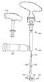
- FIG. 10is a perspective view of a right-angle drill in accordance with an embodiment of the present invention.
- FIGS. 10A-Bare perspective views of a portion of the right-angle drill of FIG. 10 in two different configurations.
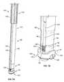
- FIG. 11Ais a perspective view of a portion of a cross bar inserter connected to a cross bar in accordance with an embodiment of the present invention.
- FIG. 11Bis a perspective view of a method of insertion of a cross bar into the assembly of FIG. 8 .
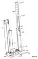
- FIG. 12Ais a perspective view of a method of persuading the cross bar into the assembly of FIG. 8 .
- FIG. 12Bis a perspective, sectional view of the method of FIG. 12A .
- FIG. 13is a perspective view of a method of removing the blades from the integrated connectors of the assembly of FIG. 8 .
- proximal and proximal mostrefer to locations closer to a user or operator of the device or method being described and that “distal” and “distal most” refer to locations further from a user or operator of the device or method being described.
- FIG. 1a perspective view illustrates a portion of a spine 10 .
- FIG. 1illustrates only the bony structures; accordingly, ligaments, cartilage, and other soft tissues are omitted for clarity.
- the spine 10has a cephalad direction 12 , a caudal direction 14 , an anterior direction 16 , a posterior direction 18 , and a medial/lateral axis 20 , all of which are oriented as shown by the arrows bearing the same reference numerals.
- “left” and “right”are used with reference to a posterior view, i.e., a view from behind the spine 10 .
- Medialrefers to a position or orientation toward a sagittal plane (i.e., plane of symmetry that separates left and right sides from each other) of the spine 10
- lateralrefers to a position or orientation relatively further from the sagittal plane.
- the spine 10 illustrated in FIG. 1includes a first vertebra 22 , a second vertebra 24 , and a third vertebra 26 .
- Connecting elements 30 of a spinal fusion constructare connected to respective pedicles 36 , 38 , 40 on the right side of the respective first, second, and third vertebrae 22 , 24 , 26 .
- the connecting elements 30each include a pedicle screw (not shown) implanted in the respective pedicles 36 , 38 , 40 and a cage 42 for receiving a spinal fusion rod 44 therein.
- the cages 42may be polyaxially coupled to the respective pedicle screws.
- Each connecting element 30may also include a set screw 45 for securing the rod 44 within the cage 42 .
- the connecting elementsmay have the same structure as the connecting elements described in the '798 patent, and the connecting elements 30 and the rod 44 may have been percutaneously inserted in the same manner as described in that patent. That is, the connecting elements 30 may have been inserted through separate incisions with the help of guide wires and/or dilators, and the rod 44 may have been inserted with the help of cannulas secured to the connecting elements 30 .
- a construct in accordance with the present inventionmay include a plurality of connecting elements 30 a with an associated rod 44 a extending generally parallel to a plurality of connecting elements 30 b with an associated rod 44 b .
- the spineis not illustrated in FIG. 2 , the construct illustrated in FIG.
- the rods 44 a and 44 bextend generally parallel to the longitudinal axis of the spine with the spinous processes of the spine extending between the rods 44 a and 44 b.
- cross links 46may extend between and be connected to both rods 44 a and 44 b . Desirably such cross links 46 help to stabilize and increase rigidity of the spinal fusion construct.
- the cross links 46may include connectors 48 secured to each rod 44 a,b and cross bars 50 received within and secured to the connectors 48 by blockers 52 , as discussed in more detail below. A system and method for percutaneously installing such cross links 46 into a spinal fusion construct follows below.
- the cross links 46may then be installed. First, the surgeon may determine at which locations along the rods 44 the cross links 46 are to be located. Although the connectors 48 of the present invention are desirably structured so as to be positionable at any location along the rods 44 , in some preferred spinal fusion constructs in accordance with the present invention the connectors 48 may be located close to the connecting elements 30 . It is believed that such placement of the cross links 46 may increase the stability of the spinal fusion construct.
- the body tissue between the skin and each of those locationsmay be dilated.
- the dilationmay be performed by inserting a dilation system including a generally tubular dilator 54 , as shown in FIG. 3A , through an incision in the skin to the desired location along the rod 44 .
- the dilator 54has a proximal end 56 and a distal end 58 and defines a passageway 57 therealong.
- the distal end 58may have an attachment portion 60 for attachment to the rod 44 .
- the attachment portion 60may include a recess 62 shaped to receive at least a portion of the rod 44 therein.
- the attachment portion 60may be structured to snap onto the rod 44 by deforming when the rod 44 is received within the recess 62 .
- a slot 64may be provided to facilitate such deformation.
- a pathway between the skin incision and the desired location along the rod 44may be sequentially dilated by a series of successively larger dilators inserted one over another, for example as discussed in the '798 patent, after which the dilator 54 may be inserted over the last of such dilators.
- a single inner dilator 66as shown in FIG.
- the inner dilator 66may be generally tubular structure sized to be closely received within the dilator 54 and having a proximal end 68 and a distal end 70 .
- the distal end 70may be tapered, as shown in FIG. 3B , in order to gently spread the tissue apart along the pathway as the inner dilator 66 is inserted.
- a dilation systemmay include a dilator 72 , as shown in FIG. 4B , which may be structured to engage a percutaneous access device connected to one of the connecting elements 30 .
- the percutaneous access devicemay be in the form of those described in the '355 patent and the '798 patent.
- the percutaneous access devicemay be a cannula 74 defined by a two blades 76 connected to opposing sides of the cage 42 .
- the blades 76may be separately formed from and detachably connectable to the cage 42 of the connecting element 30 by a distal tab 80 , as described in certain embodiments of the '798 patent.
- the cannula 74may be defined by blades that are integrally formed with the cage 42 and connected thereto by frangible portions (e.g., reduced thickness portions, which may be defined by grooves formed in either or both of the interior and exterior surfaces of cannula at the junction between the blades and the cage), whereby the blades are detachable from the cage 42 breaking the blades away from the cage 42 at the frangible portions.
- frangible portionse.g., reduced thickness portions, which may be defined by grooves formed in either or both of the interior and exterior surfaces of cannula at the junction between the blades and the cage
- the dilator 72has a proximal end 81 and a distal end 83 and defines a passageway 85 therealong, and the dilator 72 may include a generally tubular cannula 82 and an attachment structure 84 constructed to engage the blades 76 .
- the attachment structure 84may include a plurality of receivers 86 extending laterally from the cannula 82 , each of the receivers 86 having a channel 88 therealong shaped to receive one of the blades 76 therein.
- the dilator 72may be inserted into the body by inserting the proximal ends 90 of the blades 76 into the channels 88 of the receivers 86 at the distal end 83 of the dilator and advancing the dilator 72 distally through the body tissue.
- the cannula 82 of the dilatormay first pass through an incision in the skin, such as an incision adjacent to the cannula 74 defined by the blades 76 , and then may progress distally through the body tissue to a desired location along the rod 44 , such as a location adjacent to the cage 42 .
- a pathway between the skin incision and the desired location along the rod 44may be dilated in advance of the movement of the cannula 82 along that pathway.
- a dilator(not shown) having a tapered distal end, such as a dilator structured similarly to the inner dilator 66 of FIG. 3B , may be inserted along the pathway in advance of the cannula 82 .
- a dilatormay be received within the passageway 85 of the cannula 82 with the tapered distal end of the dilator projecting distally of the cannula 82 so as to gently spread the tissue apart along the pathway as the dilator 72 is inserted.
- the body tissue between the skin and each of the desired locations for the connectors 48may be dilated using one or a combination of dilation systems, such as those illustrated in FIGS. 3A-C and 4 B.
- one or more toolsmay be used to push tissue away from the desired locations for the connectors 48 .
- an elongate tool(not shown) may be inserted along the passageways 57 , 85 defined by the dilators 54 , 72 , and the distal end of such tool may be used to push any tissue away from the desired locations for the connectors 48 .
- the connectors 48may then be inserted along the passageways 57 , 85 to the desired locations along the rods 44 .
- the connectors 48may be initially connected to a percutaneous access device before placement within the body.
- the percutaneous access devicemay be in the form of a cannula 92 defined by a two blades 94 extending proximally from opposing sides of the connector 48 .
- the blades 94may be integrally formed with the connector 48 and connected thereto by frangible portions 96 at the distal end 97 of the cannula 92 , thus forming an integrated connector 98 having a proximal end 101 and a distal end 103 , with the connector 48 being located at the distal end 103 of the integrated connector 98 .
- the blades 94may be separately formed from and detachably connectable to the connector 48 , such as by distal tabs, as described in certain embodiments of the percutaneous access devices in the '798 patent.
- the blades 94may define a pass-through slot 100 extending between them.
- the percutaneous access devicemay define a slot opening radially outward in only one direction along the cannula 92 .
- a separately formed ring 102may be connected to both blades 94 , preferably towards the proximal end 99 of the cannula 92 , so as to stabilize the blades 94 and resist their becoming detached from the connector 48 prematurely.
- the ring 102may be shaped as an annular member having channels formed therethrough for receiving the blades 94 therein.
- the ring 102may be in the form of abutment member as described in the '798 patent.
- the ring 102may be connected to the blades 94 before the integrated connector 98 is inserted into the body or after the integrated connector 98 is connected to the rod 44 within the body.
- the connector 48may include a connecting member 104 and a retaining member 106 .
- the retaining member 106may be in the form of a separately formed ring encircling a portion of the connecting member 104 .
- FIG. 6Ais a cross-sectional view of a portion of an integrated connector 98 towards its distal end 103 with the retaining member 106 removed, the cross-section being taken along a plane perpendicular to the slot 100 .
- the connector 48includes a rod receiving portion 108 for receiving a rod 44 and a cross bar receiving portion 110 for receiving a cross bar 50 .
- the cross bar receiving portion 110may include two proximally extending arms 112 defining a receptacle 114 therebetween shaped to receive a cross bar 50 therein in an orientation perpendicular to the longitudinal axis 116 of the integrated connector 98 .
- the receptacle 114may be in form of a pass through slot communicating with the slot 100 of cannula 92 at the distal end 97 of the cannula 92 .
- the cannula 92may include a threaded portion 118 at least along the distal end 97 thereof, and the cross bar receiving portion 110 of the connector 48 may include a threaded portion 120 along the arms 112 thereof.
- the threaded portion 118 of the cannula 92may not be present while the threaded portion 120 of the connector 48 is present.
- the arms 112 of the cross bar receiving portion 110may each be connected to a respective one of the blades 94 at one of the frangible portions 96 .
- the frangible portions 96may be defined by reduced thickness portions, such as by one or both of interior grooves 122 and exterior grooves 124 .
- the interior and exterior grooves 122 , 124may be substantially aligned with one another along the longitudinal axis of the integrated connector 98 , as shown in FIG. 6A , to define the reduced thickness portion of the frangible portion 96 .
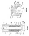
- FIG. 6Bis a cross-sectional view of a portion of an integrated connector 98 towards its distal end 103 with the retaining member 106 removed, the cross-section being taken along a plane parallel to the slot 100 and perpendicular to the view of FIG. 6A .
- the view of FIG. 6Bfocuses on the rod receiving portion 108 of the connector 48 .
- the rod receiving portion 108may include two distally extending arms 126 defining a receptacle 128 therebetween shaped to receive a rod 44 therein in an orientation perpendicular to the longitudinal axis 116 of the integrated connector 98 and generally perpendicular to the orientation of the cross bar 50 when the cross bar 50 is received within the cross bar receiving portion 110 of the connector 48 .
- the receptacle 128may be in form of a pass through slot open to the distal end 103 of the integrated connector 98 .
- the rod receiving portion 108may be structured to snap onto the rod 44 by deforming when the rod 44 is inserted into the receptacle 128 .
- the arms 126may deflect away from one another during such insertion.
- One or more slots 130 extending further into the rod receiving portion 108 from the receptacle 128may be provided to facilitate such deflection of the arms 126 .
- the opening 132 into the receptacle 128 at the distal end 103 of the integrated connector 98may also have a chamfer 134 to ease insertion of the rod 44 into the receptacle 128 and initiate the deflection of the arms 126 during such insertion.
- the retaining member 106desirably provides stiffness to the connecting member 104 , such as by restraining the arms 126 from deflecting too easily. In that manner, the retaining member 106 desirably helps to secure the connector 48 to the rod 44 by restraining the rod 44 from becoming dislodged from the receptacle 128 when not desired.
- the retaining member 106when engaged with and encircling the connecting member 104 , may engage the connecting member 104 along engagement surfaces 136 . As shown in FIG. 7B , the retaining member 106 may take the form of a generally annular ring encircling the connecting member 104 .
- the retaining member 106may include proximally-extending, arcuate deviations 138 on opposing sides of the retaining member 106 and aligned with the receptacle 128 , so as to not interfere with a rod 44 placed into and extending laterally through the receptacle 128 .
- a connector inserter 140may be engaged with an integrated connector 98 in order to assist with the insertion of the integrated connector 98 along the passageways 57 , 85 of the dilators 54 , 72 and to the desired locations along the rods 44 .
- the connector inserter 140may have a proximal end 142 and a distal end 144 with an elongate shaft 146 extending therebetween, the shaft 146 being configured to be received within the cannula 92 of the integrated connector 98 .
- the proximal end 142 of the connector inserter 140may include a handle 148
- the distal end 144 of the connector inserter 140may include a threaded portion 150 for engagement with the threaded portion 120 of the connector 48 , as shown in FIG. 7B .
- the connector inserter 140may thus be engaged with the integrated connector 98 by advancing the connector inserter 140 distally within the cannula 92 and rotating the threaded portion 150 of the connector inserter 140 into engagement with the threaded portion 120 of the connector 48 .
- the integrated connector 98may then be inserted into the body by grasping the handle 148 of the connector inserter 140 and using the connector inserter 140 to manipulate the integrated connector 98 down along the one of the passageways 57 , 85 of the dilators 54 , 72 until the rod receiving portion 108 of the connector 48 snaps into engagement with the rod 44 .
- the connector inserter 140may then be removed by rotating the threaded portion 150 of the connector inserter 140 out of engagement with the threaded portion 120 of the connector 48 and withdrawing the connector inserter 140 proximally. After any of the integrated connectors 98 are engaged with the rods 44 , the associated dilators 54 , 72 may be removed.
- a ring 102see FIG.
- a ring 102may be connected to the blades 94 before the integrated connector 98 is inserted into the body through the dilator 54 , 72 .
- FIG. 8illustrates two integrated connectors 98 connected to respective rods 44 a,b adjacent respective cages 42 a,b of respective connecting elements 30 a,b .
- the cannulas 92 of the integrated connectors 98thus desirably provide percutaneous pathways through body tissue from the connectors 48 to respective incisions in the skin.
- the connecting element 30 awould be implanted in a pedicle on one side of the longitudinal axis of the spine, and the connecting element 30 b would be implanted in a pedicle on the other side of the longitudinal axis of the spine, such that the rods 44 a and 44 b extend generally parallel to the longitudinal axis of the spine with the spinous processes of the spine extending between the rods 44 a and 44 b .
- One of the cages 42 a in FIG. 8is illustrated as having two blades 76 of a cannula 74 of a percutaneous access device connected thereto.
- the slots 100 of the integrated connectors 98may be generally aligned with one another and may extend generally perpendicular to the rods 44 a,b.
- a linkage 152may be connected to the proximal ends 101 of the integrated connectors 98 after the integrated connectors 98 are connected to the respective rods 44 a,b .
- the linkage 152may include a rail 154 having a movable link 156 slidably connected thereto and having a fixed link 158 rigidly connected to one end.
- the movable link 156may have a locked and an unlocked configuration, such that the movable link 156 freely slides along the rail 154 to vary the distance between the two links 156 , 158 in the unlocked configuration, and such that the movable link 156 resists movement along the rail 154 in the locked configuration.
- the rail 154may include graduations 160 along its length, which graduations 160 may be marked with measurements.
- Each link 156 , 158may be connected to the proximal end 101 of an integrated connector 98 , as shown in FIG. 9 , to stabilize the integrated connectors 98 .
- the graduations 160may also help to determine the distance between the connectors 98 , which may assist with the determination of an appropriate length for a cross bar 50 to be inserted between the connectors 48 .
- a pathway between the connectors 48may first be created.
- one or more elongate tools(not shown) may be passed down through the cannulas 92 of one or more of the integrated connectors 98 and through the slots 100 so as to separate or cut away tissue between the connectors 48 .
- the spinous processes between the generally parallel rods 44 a and 44 bmay interfere with the desired placement of a cross bar 50 . In such cases, a portion of the interfering bone may be removed.
- One exemplary tool for performing such bone removalincludes a right-angle drill 162 as shown in FIG. 10 .
- the right-angle drill 162may have a proximal end 166 and a distal end 168 and an elongated extender 164 extending therebetween.
- the distal end 168 of the right angle drill 162may be structured to sit stably within a receptacle 114 of a cross bar receiving portion 110 of a connector 48 .
- a drill bit 172may be connected to a drill bit attachment mechanism 170 located at the distal end 168 of the right-angle drill 162 .
- the drill bit attachment mechanism 170may be connected to the extender 164 by a right-angle bend 169 , such that the drill bit 172 extends in a generally perpendicular direction to the extender 164 .
- the drill bit attachment mechanism 170may be structured for detachable connection to the drill bit 172 .
- the drill bit 172may include a connection end 171 structured for removable insertion into a receiver opening (not shown) in the drill bit attachment mechanism 170 . After the connection end 171 is positioned within the receiver opening, a locking lever 173 may be pivoted downwardly, as shown in FIG. 10B , to secure the drill bit 172 within the drill bit attachment mechanism 170 .
- the extender 164 of the right-angle drill 162may be structured as a hollow shaft, so that a drive shaft (not shown) may be rotatably received within the extender 164 for driving the rotation of the drill bit 172 .
- the drive shaftmay be operably coupled to the drill bit 172 via a mechanism (not shown) for transmitting the rotary motion of the drive shaft through the right-angle bend 169 , such as a universal joint, a bevel gear, a worm gear, or any other suitable mechanism.
- the extender 164may include one or more holes 175 along its length, which holes 175 may communicate with the interior of the extender 164 for cleaning or other purposes.
- the proximal end 166 of the extender 164may be connected to a drive handle 174 for actuating the rotation of the drill bit 172 .
- the drive handle 174may be detachably connected to a connector (not shown) at the proximal end 166 of the extender 164 , which connector is operably coupled to the drive shaft.
- other types of drive handlese.g., drive handle 174 ′ illustrated in FIG. 10
- the right-angle drill 162may be structured such that rotation of the drive handle 174 causes rotation of the drill bit 172 (e.g., in a 1:1 ratio, although other ratios may be used).
- the right-angle drill 162may incorporate a motor for electrical power driven rotation of the drill bit 172 .
- the right-angle drill 162may include a support handle 176 located along the extender 164 between the proximal end 166 and the distal end 168 .
- the support handle 176may extend in a generally perpendicular orientation from the extender 164 .
- an appropriate drill bit 172may first be connected to the drill bit attachment mechanism 170 .
- a drill bit 172 having an appropriate lengthmay be connected to the drill bit attachment mechanism 170 .
- the right-angle drill 162may then be inserted along a cannula 92 of one of the integrated connectors 98 , and the drill bit 172 may extend through a slot 100 of the integrated connector 98 towards a location on a spinous process where the surgeon desires an opening to be formed.
- the right-angle drill 162may be positioned such that, at least initially, the distal end 168 rests in the receptacle 114 of the cross bar receiving portion 110 of a connector 48 .
- the drive handle 174may then be rotated in order to rotate the drill bit 172 and form an opening through the spinous process. Fluoroscopy may be used to help navigate the drill bit 172 within the body, and the perpendicularly extending support handle 176 may be used both to support the right-angle drill 162 and to act as a directional vector, as the support handle 176 may desirably extend generally parallel to the drill bit 172 .
- the right-angle drill 162may be removed from the body.
- the cross bar 50Before a cross bar 50 is inserted into the body and connected between two connectors 48 , the cross bar 50 may first be bent and/or cut as needed so that the cross bar 50 is appropriately sized and shaped to extend between the connectors 48 .
- the cross bar 50may be attached to a cross bar inserter 178 , as shown in FIGS. 11A-B , before insertion into the body.
- the cross bar inserter 178may be an elongate tool having a handle 184 at a proximal end 180 and a connection structure 186 at the distal end 182 for detachably connecting to a cross bar 50 .
- the proximal end 180 of the cross bar inserter 178may also include an actuator 188 configured to operate the connection structure 186 so as to selectively secure and release the cross bar 50 to the connection structure 186 .
- the handle 184 of the cross bar inserter 178may be grasped and used to manipulate the cross bar 50 down along the cannula 92 of one of the integrated connectors 98 , through the slot 100 , and across through body tissue (including through an opening in the spinous process, if applicable), as illustrated in FIG. 11B , until the cross bar 50 extends between the integrated connectors 98 in a position proximate the connectors 48 attached to each parallel rod 44 a,b.
- the cross bar 50may be moved into a final position extending between and simultaneously received by the receptacles 114 of the cross bar receiving portions 110 of each of the connectors 48 .
- the cross bar 50may be moved into that final position using the cross bar inserter 178 .
- the cross bar 50may be moved into the final position using either or a combination of a persuader 190 and a blocker inserter 192 , as shown in FIGS. 12A-B .
- the persuader 190may have a generally tubular member 191 having a distal end 194 and a proximal end 196 .
- the tubular member 191may be sized to fit over an integrated connector 98 such that the integrated connector 98 is received inside the tubular member 191 , as shown in FIGS. 12A-B .
- a handle 198may be connected to the tubular member 191 towards its proximal end 196 .
- the blocker inserter 192may be an elongate tool having a handle 204 at its proximal end 206 and a blocker interface 200 at its distal end 202 .
- the blocker interface 200may be shaped to engage a correspondingly shaped interface 208 (such as a hexagonally shaped recess) on a blocker 52 .
- the blocker 52may be an externally threaded component, similar to the set screws 45 of the connecting elements 30 implanted in the pedicles, and the threads 210 of the blocker 52 may be structured to engage the threaded portion 118 towards the distal end 97 of the cannula 92 and the threaded portion 120 of the cross bar receiving portion 110 of the connector 48 .
- the handle 198 of a persuader 190may be grasped and manipulated so that the tubular member 191 is fit over the proximal end 101 of an integrated connector 98 and advanced distally towards the transversely oriented cross bar 50 .
- the distal end 194 of the tubular member 191may contact the cross bar 50 and push it distally towards and into the final position within the receptacle 114 of the connector 48 .
- a blocker inserter 192may have a blocker 52 placed onto the blocker interface 200 at its distal end 202 , after which the blocker inserter 192 may be advanced distally between the blades 94 of the integrated connector 98 .
- the blocker inserter 192may be rotated to advance the blocker 52 along the threaded portion 118 . Further advancement of the blocker 52 may cause the threads 210 of the blocker 52 to engage and advance along the threaded portion 120 of the connector 48 .
- the blocker 52may be advanced in this manner until the cross bar 50 is securely captured within the receptacle 114 .
- the blocker 52may contact the cross bar 50 and push the cross bar 50 distally towards and into the final position within the receptacle 114 .
- both the persuader 190 and the blocker inserter 192may be used, as shown in FIGS. 12A-B .
- the persuader 190may be used to push the cross bar 50 distally, as described above, until the cross bar 50 is at least within the threaded portion 118 of the cannula 92 .
- the blocker inserter 192 connected to the blocker 52may be advanced, as described above, to push the cross bar 50 the remaining distance towards and into the final position within the receptacle 114 .
- the blocker inserter 192may be constructed as a torque wrench, such that the torque applied by the blocker interface 200 is limited to a pre-selected amount. In other embodiments, the blocker inserter 192 may not be so constructed, and a separate torque-limiting blocker inserter (not shown) may be provided. In either case, the final tightening of the blocker 52 into the connector 48 so as to secure the cross bar 50 therein may be performed with a torque limiting tool. Such a tool may be set to limit the tightening torque to, for example, 8 Nm (newton-meters).
- the cross bar 50may be released from the cross bar inserter 178 , and the cross bar inserter 178 may be removed from the body, at any point after the cross bar 50 is in a desired position within the body.
- the cross bar inserter 178may be removed before the cross bar 50 is moved into the final position using either or both of the persuader 190 and the blocker inserter 192 .
- the cross bar inserter 178may remain attached to the cross bar 50 during the final positioning with the persuader 190 and the blocker inserter 192 , preferably in a location out of the way of those tools.
- any insertion tools that remain positioned within the bodymay be removed from the body.
- the cannula 92may then be removed from the connector 48 .
- the blades 94 of the cannulamay be separately disconnected from the connector 48 and removed from the body.
- the blades 94may be disconnected from the connector 48 by breaking each of the blades 94 away from the connector 48 at the frangible portions 96 .
- FIG. 13One method for breaking the blades 94 of the integrated connector 98 away from the connector 48 is illustrated in FIG. 13 .
- Such a methodmay include separately engaging each blade 94 with a blade remover 212 .
- the blade remover 212may be an elongate tool having a proximal end 214 and a distal end 216 .
- the blade remover 212may include a handle 218 at the proximal end 214 and may have a channel 220 formed therein open to the distal end 216 .
- the channel 220may be constructed to receive a blade 94 of an integrated connector 98 therein.
- the blade remover 212may also include a spring clip 222 in communication with the channel 220 such that the spring clip 222 may securely engage a blade 94 when the blade 94 is positioned within the channel 220 , preferably in order to retain the blade 94 within the blade remover 212 after the blade 94 has been detached from the connector 48 .
- the blade remover 212may also include a release mechanism (not shown) movably engaged within the channel 220 so as to eject the blade 94 from the channel 220 after the detached blade 94 has been removed from the body.
- the release mechanismmay include a slider received within a longitudinal track along the channel 220 , such that distal movement of the slider will push the blade 94 out of the channel 220 at the distal end 216 of the blade remover 212 .
- the blade remover 212is engaged to a blade 94 by sliding the blade remover 212 distally over the blade 94 until the blade is received within the channel 220 .
- a usermay pivot the blade remover 212 , and thus the blade received therein, about the frangible portion 96 until the frangible portion 96 fractures, thus disconnecting the blade 94 from the connector 48 .
- the blade remover 212may then be removed from the body, and desirably the spring clip 222 may retain the blade 94 within the blade remover 212 until the blade remover 212 is removed from the body.
- the detached blade 94may be ejected from the channel 220 by actuating the release mechanism.
- the blade remover 212may then be used again by repeating the above steps to remove other blades 94 from the connectors 48 .
- the rod receiving portion 108is illustrated as being integrally formed with the cross bar receiving portion 110 , in other embodiments of the connectors in accordance with the present invention, the rod receiving portion may be separately formed from the cross bar receiving portion, and both such parts may be coupled together to form the connector. In one such an embodiment, the rod receiving portion and the cross bar receiving portion may be polyaxially coupled together.
- the connectors 48 described hereinare structured for direct engagement with the rods 44
- other embodiments of the connectors in accordance with the present inventionmay be otherwise engageable with portions of the spinal fusion construct.
- the connectormay be structured to straddle the cage 42 of a connecting element 30 while the connector is connected to the rod 44 on each side of the cage 42 .
- the connectormay not be engaged with the rod at all, and may instead, for example, be structured to be directly affixed to the cage 42 of a connecting element 30 .
- the various components described hereinare preferably constructed of materials safe for use in the body.
- many of the components, including the components of the integrated connector 98may be constructed from a titanium alloy.
Landscapes
- Health & Medical Sciences (AREA)
- Orthopedic Medicine & Surgery (AREA)
- Life Sciences & Earth Sciences (AREA)
- Surgery (AREA)
- Neurology (AREA)
- Heart & Thoracic Surgery (AREA)
- General Health & Medical Sciences (AREA)
- Biomedical Technology (AREA)
- Nuclear Medicine, Radiotherapy & Molecular Imaging (AREA)
- Medical Informatics (AREA)
- Molecular Biology (AREA)
- Animal Behavior & Ethology (AREA)
- Engineering & Computer Science (AREA)
- Public Health (AREA)
- Veterinary Medicine (AREA)
- Dentistry (AREA)
- Oral & Maxillofacial Surgery (AREA)
- Surgical Instruments (AREA)
- Prostheses (AREA)
Abstract
Description
Claims (21)
Priority Applications (3)
| Application Number | Priority Date | Filing Date | Title |
|---|---|---|---|
| US14/201,213US9827020B2 (en) | 2013-03-14 | 2014-03-07 | Percutaneous spinal cross link system and method |
| US15/797,592US10912590B2 (en) | 2013-03-14 | 2017-10-30 | Percutaneous spinal cross link system and method |
| US17/168,598US12059178B2 (en) | 2013-03-14 | 2021-02-05 | Percutaneous spinal cross link system and method |
Applications Claiming Priority (2)
| Application Number | Priority Date | Filing Date | Title |
|---|---|---|---|
| US201361782278P | 2013-03-14 | 2013-03-14 | |
| US14/201,213US9827020B2 (en) | 2013-03-14 | 2014-03-07 | Percutaneous spinal cross link system and method |
Related Child Applications (1)
| Application Number | Title | Priority Date | Filing Date |
|---|---|---|---|
| US15/797,592ContinuationUS10912590B2 (en) | 2013-03-14 | 2017-10-30 | Percutaneous spinal cross link system and method |
Publications (2)
| Publication Number | Publication Date |
|---|---|
| US20140277145A1 US20140277145A1 (en) | 2014-09-18 |
| US9827020B2true US9827020B2 (en) | 2017-11-28 |
Family
ID=50289444
Family Applications (3)
| Application Number | Title | Priority Date | Filing Date |
|---|---|---|---|
| US14/201,213Active2034-12-09US9827020B2 (en) | 2013-03-14 | 2014-03-07 | Percutaneous spinal cross link system and method |
| US15/797,592Active2034-06-11US10912590B2 (en) | 2013-03-14 | 2017-10-30 | Percutaneous spinal cross link system and method |
| US17/168,598Active2035-08-21US12059178B2 (en) | 2013-03-14 | 2021-02-05 | Percutaneous spinal cross link system and method |
Family Applications After (2)
| Application Number | Title | Priority Date | Filing Date |
|---|---|---|---|
| US15/797,592Active2034-06-11US10912590B2 (en) | 2013-03-14 | 2017-10-30 | Percutaneous spinal cross link system and method |
| US17/168,598Active2035-08-21US12059178B2 (en) | 2013-03-14 | 2021-02-05 | Percutaneous spinal cross link system and method |
Country Status (5)
| Country | Link |
|---|---|
| US (3) | US9827020B2 (en) |
| EP (1) | EP2777572B1 (en) |
| JP (1) | JP6340221B2 (en) |
| AU (1) | AU2014201601B2 (en) |
| CA (2) | CA2980049C (en) |
Cited By (1)
| Publication number | Priority date | Publication date | Assignee | Title |
|---|---|---|---|---|
| US20230240728A1 (en)* | 2015-10-27 | 2023-08-03 | Ctl Medical Corporation | Modular rod reduction tower and related methods |
Families Citing this family (25)
| Publication number | Priority date | Publication date | Assignee | Title |
|---|---|---|---|---|
| CN102497828B (en)* | 2009-05-20 | 2015-09-09 | 斯恩蒂斯有限公司 | What patient installed retracts part |
| US9339309B1 (en)* | 2012-10-11 | 2016-05-17 | Nuvasive, Inc. | Systems and methods for inserting cross-connectors |
| US20140257402A1 (en)* | 2013-03-08 | 2014-09-11 | The Cleveland Clinic Foundation | Surgical system for positioning a patient and marking locations for a surgical procedure |
| US20140277163A1 (en)* | 2013-03-15 | 2014-09-18 | Ryan Kretzer | Reinforcement systems for spine stabilization constructs |
| US9668789B2 (en) | 2013-03-15 | 2017-06-06 | Ebi, Llc | Reduction instrument, surgical assembly including a reduction instrument and related method |
| BR112017005408B1 (en)* | 2014-09-19 | 2022-05-10 | Duet Spine Holdings, Llc | Single-level fusion system and assembly method thereof |
| EP3193755B1 (en) | 2014-09-19 | 2022-02-09 | In Queue Innovations, LLC | Fusion systems of assembly and use |
| US10368923B2 (en)* | 2014-10-28 | 2019-08-06 | Neurostructures, Inc. | Bone fixation system |
| US9763703B2 (en) | 2015-05-05 | 2017-09-19 | Degen Medical, Inc. | Cross connectors, kits, and methods |
| US10980641B2 (en) | 2017-05-04 | 2021-04-20 | Neurostructures, Inc. | Interbody spacer |
| US10512547B2 (en) | 2017-05-04 | 2019-12-24 | Neurostructures, Inc. | Interbody spacer |
| US10456174B2 (en)* | 2017-07-31 | 2019-10-29 | Medos International Sarl | Connectors for use in systems and methods for reducing the risk of proximal junctional kyphosis |
| US10463403B2 (en) | 2017-07-31 | 2019-11-05 | Medos International Sarl | Systems and methods for reducing the risk of proximal junctional kyphosis using a bone anchor or other attachment point |
| US11076892B2 (en) | 2018-08-03 | 2021-08-03 | Neurostructures, Inc. | Anterior cervical plate |
| WO2020035958A1 (en)* | 2018-08-16 | 2020-02-20 | Medtronic Sofamor Danek, Co., Ltd. | Spinal implant system and method |
| US11071629B2 (en) | 2018-10-13 | 2021-07-27 | Neurostructures Inc. | Interbody spacer |
| US11259940B2 (en) | 2019-06-28 | 2022-03-01 | Mis Spine Ip, Llc | Systems and methods for percutaneous spinal interbody fusion (PSIF) |
| CN110680489B (en)* | 2019-11-07 | 2024-08-20 | 浙江省人民医院 | Thoracic vertebra yellow ligament ossification compound backward moving device and application method thereof |
| US11382761B2 (en) | 2020-04-11 | 2022-07-12 | Neurostructures, Inc. | Expandable interbody spacer |
| US11304817B2 (en) | 2020-06-05 | 2022-04-19 | Neurostructures, Inc. | Expandable interbody spacer |
| US11717419B2 (en) | 2020-12-10 | 2023-08-08 | Neurostructures, Inc. | Expandable interbody spacer |
| JP7702694B2 (en)* | 2021-04-08 | 2025-07-04 | ミズホ株式会社 | Percutaneous Spinal Stabilization System |
| US12059168B2 (en) | 2021-06-16 | 2024-08-13 | Ludwig David Orozco Castillo | Systems and methods for ball probe ultrasonic foraminotomy |
| US20240299065A1 (en)* | 2023-03-08 | 2024-09-12 | Nuvasive, Inc. | Percutaneous posterior fixation |
| US20250072939A1 (en)* | 2023-08-29 | 2025-03-06 | Oluwatodimu Richard Raji | Percutaneous Minimally Invasive Cross Connector System |
Citations (257)
| Publication number | Priority date | Publication date | Assignee | Title |
|---|---|---|---|---|
| US3788318A (en) | 1972-06-12 | 1974-01-29 | S Kim | Expandable cannular, especially for medical purposes |
| US3789852A (en) | 1972-06-12 | 1974-02-05 | S Kim | Expandable trochar, especially for medical purposes |
| US3892232A (en) | 1973-09-24 | 1975-07-01 | Alonzo J Neufeld | Method and apparatus for performing percutaneous bone surgery |
| US4083370A (en) | 1976-11-03 | 1978-04-11 | Taylor John D | Bloat relief tube and holder |
| US4269184A (en) | 1980-02-28 | 1981-05-26 | Montgomery William W | Silicone tracheal cannula |
| US4350151A (en) | 1981-03-12 | 1982-09-21 | Lone Star Medical Products, Inc. | Expanding dilator |
| US4409968A (en) | 1980-02-04 | 1983-10-18 | Drummond Denis S | Method and apparatus for engaging a hook assembly to a spinal column |
| US4411259A (en) | 1980-02-04 | 1983-10-25 | Drummond Denis S | Apparatus for engaging a hook assembly to a spinal column |
| US4448191A (en) | 1981-07-07 | 1984-05-15 | Rodnyansky Lazar I | Implantable correctant of a spinal curvature and a method for treatment of a spinal curvature |
| US4449532A (en) | 1980-07-08 | 1984-05-22 | Karl Storz | Dilator to facilitate endoscope insertion into the body |
| US4474046A (en) | 1982-06-18 | 1984-10-02 | Zimmer, Inc. | Rod bender |
| US4545374A (en) | 1982-09-03 | 1985-10-08 | Jacobson Robert E | Method and instruments for performing a percutaneous lumbar diskectomy |
| US4562832A (en) | 1984-01-21 | 1986-01-07 | Wilder Joseph R | Medical instrument and light pipe illumination assembly |
| US4611581A (en) | 1983-12-16 | 1986-09-16 | Acromed Corporation | Apparatus for straightening spinal columns |
| US4653481A (en) | 1985-07-24 | 1987-03-31 | Howland Robert S | Advanced spine fixation system and method |
| US4790297A (en) | 1987-07-24 | 1988-12-13 | Biotechnology, Inc. | Spinal fixation method and system |
| US4817587A (en) | 1987-08-31 | 1989-04-04 | Janese Woodrow W | Ring para-spinal retractor |
| US4862891A (en) | 1988-03-14 | 1989-09-05 | Canyon Medical Products | Device for sequential percutaneous dilation |
| US4887595A (en) | 1987-07-29 | 1989-12-19 | Acromed Corporation | Surgically implantable device for spinal columns |
| US4899729A (en) | 1985-05-30 | 1990-02-13 | Gill Steven S | Expansible cannula |
| US4913134A (en) | 1987-07-24 | 1990-04-03 | Biotechnology, Inc. | Spinal fixation system |
| US4957495A (en) | 1987-04-01 | 1990-09-18 | Patrick Kluger | Device for setting the spinal column |
| US4984564A (en) | 1989-09-27 | 1991-01-15 | Frank Yuen | Surgical retractor device |
| US5010879A (en) | 1989-03-31 | 1991-04-30 | Tanaka Medical Instrument Manufacturing Co. | Device for correcting spinal deformities |
| US5027793A (en) | 1990-03-30 | 1991-07-02 | Boehringer Mannheim Corp. | Surgical retractor |
| US5035232A (en) | 1987-10-24 | 1991-07-30 | Aesculap Ag | Retractor |
| US5125396A (en) | 1990-10-05 | 1992-06-30 | Ray R Charles | Surgical retractor |
| US5139487A (en) | 1990-11-28 | 1992-08-18 | Baber Bloomfield W | Laparoscopic surgical instrument apparatus |
| US5171279A (en) | 1992-03-17 | 1992-12-15 | Danek Medical | Method for subcutaneous suprafascial pedicular internal fixation |
| US5183464A (en) | 1991-05-17 | 1993-02-02 | Interventional Thermodynamics, Inc. | Radially expandable dilator |
| EP0528177A2 (en) | 1991-08-17 | 1993-02-24 | Aesculap Ag | Internal fixator for the correction of a lumbar spondyldisthesis |
| EP0528562A2 (en) | 1991-08-15 | 1993-02-24 | Smith & Nephew Richards Inc | Pedicle screw and percutaneous fixation of vertebrae |
| US5195541A (en) | 1991-10-18 | 1993-03-23 | Obenchain Theodore G | Method of performing laparoscopic lumbar discectomy |
| US5197971A (en) | 1990-03-02 | 1993-03-30 | Bonutti Peter M | Arthroscopic retractor and method of using the same |
| US5293863A (en) | 1992-05-08 | 1994-03-15 | Loma Linda University Medical Center | Bladed endoscopic retractor |
| US5295994A (en) | 1991-11-15 | 1994-03-22 | Bonutti Peter M | Active cannulas |
| USD346217S (en) | 1992-07-13 | 1994-04-19 | Acromed Corporation | Combined hook holder and rod mover for spinal surgery |
| WO1994009726A1 (en) | 1992-10-23 | 1994-05-11 | Smith & Nephew Richards Inc. | Internal fixators |
| US5312417A (en) | 1992-07-29 | 1994-05-17 | Wilk Peter J | Laparoscopic cannula assembly and associated method |
| DE4238339A1 (en) | 1992-11-13 | 1994-05-19 | Peter Brehm | Fastening screw for spinal column support rod - has hollow slotted head with female thread to accommodate grub-screw to firmly clamp rod in place |
| EP0611116A1 (en) | 1993-02-11 | 1994-08-17 | SMITH & NEPHEW RICHARDS, INC. | Spinal column retaining apparatus |
| US5360431A (en) | 1990-04-26 | 1994-11-01 | Cross Medical Products | Transpedicular screw system and method of use |
| US5373860A (en) | 1992-08-25 | 1994-12-20 | Catone; Guy A. | Apparatus for and method of contouring plates for bone fixation |
| US5377667A (en) | 1992-12-03 | 1995-01-03 | Michael T. Patton | Speculum for dilating a body cavity |
| US5381788A (en) | 1991-08-05 | 1995-01-17 | United States Surgical Corporation | Surgical retractor |
| US5395317A (en) | 1991-10-30 | 1995-03-07 | Smith & Nephew Dyonics, Inc. | Unilateral biportal percutaneous surgical procedure |
| US5409488A (en) | 1992-01-16 | 1995-04-25 | Ulrich; Heinrich | Spondylodesis implant |
| WO1995014437A1 (en) | 1993-11-25 | 1995-06-01 | Sofamor Danek Group, Inc. | Implant for an osteosynthesis device, particularly for the spine, and positioning instrument therefor |
| US5425732A (en) | 1992-01-16 | 1995-06-20 | Ulrich; Heinrich | Implant for internal fixation, particularly spondylodesis implant |
| US5439464A (en) | 1993-03-09 | 1995-08-08 | Shapiro Partners Limited | Method and instruments for performing arthroscopic spinal surgery |
| US5454365A (en) | 1990-11-05 | 1995-10-03 | Bonutti; Peter M. | Mechanically expandable arthroscopic retractors |
| US5464011A (en) | 1994-10-24 | 1995-11-07 | Bridge; Robert S. | Tracheostomy tube |
| US5480440A (en) | 1991-08-15 | 1996-01-02 | Smith & Nephew Richards, Inc. | Open surgical technique for vertebral fixation with subcutaneous fixators positioned between the skin and the lumbar fascia of a patient |
| US5490409A (en) | 1994-11-07 | 1996-02-13 | K-Medic, Inc. | Adjustable cam action rod bender for surgical rods |
| US5569290A (en) | 1995-01-30 | 1996-10-29 | Paul C. McAfee | Method of and apparatus for laparoscopic or endoscopic spinal surgery using an unsealed anteriorly inserted transparent trochar |
| US5591165A (en) | 1992-11-09 | 1997-01-07 | Sofamor, S.N.C. | Apparatus and method for spinal fixation and correction of spinal deformities |
| US5601562A (en) | 1995-02-14 | 1997-02-11 | Arthrex, Inc. | Forked insertion tool and metnod of arthroscopic surgery using the same |
| US5601590A (en) | 1993-02-04 | 1997-02-11 | General Surgical Innovations, Inc. | Expandable cannulas |
| WO1997014457A1 (en) | 1995-10-18 | 1997-04-24 | Stouder Albert E Jr | Adjustable length cannula and trocar |
| US5658286A (en) | 1996-02-05 | 1997-08-19 | Sava; Garard A. | Fabrication of implantable bone fixation elements |
| US5707359A (en) | 1995-11-14 | 1998-01-13 | Bufalini; Bruno | Expanding trocar assembly |
| US5720751A (en) | 1996-11-27 | 1998-02-24 | Jackson; Roger P. | Tools for use in seating spinal rods in open ended implants |
| US5741261A (en) | 1996-06-25 | 1998-04-21 | Sdgi Holdings, Inc. | Minimally invasive spinal surgical methods and instruments |
| US5743907A (en) | 1990-07-24 | 1998-04-28 | Acromed Corporation | Spinal column retaining method and apparatus |
| US5746720A (en) | 1995-10-18 | 1998-05-05 | Stouder, Jr.; Albert E. | Method and apparatus for insertion of a cannula and trocar |
| WO1998022030A1 (en) | 1996-11-18 | 1998-05-28 | University Of Massachusetts | Systems, methods, and instruments for minimally invasive surgery |
| US5762629A (en) | 1991-10-30 | 1998-06-09 | Smith & Nephew, Inc. | Oval cannula assembly and method of use |
| US5772594A (en) | 1995-10-17 | 1998-06-30 | Barrick; Earl F. | Fluoroscopic image guided orthopaedic surgery system with intraoperative registration |
| US5792044A (en) | 1996-03-22 | 1998-08-11 | Danek Medical, Inc. | Devices and methods for percutaneous surgery |
| US5795289A (en) | 1997-07-28 | 1998-08-18 | Wyttenbach; William H. | Speculum |
| WO1998038918A1 (en) | 1997-03-07 | 1998-09-11 | Mordechay Beyar | Systems for percutaneous bone and spinal stabilization, fixation and repair |
| US5814046A (en) | 1992-11-13 | 1998-09-29 | Sofamor S.N.C. | Pedicular screw and posterior spinal instrumentation |
| DE19726754A1 (en) | 1997-06-24 | 1999-02-04 | Aesculap Ag & Co Kg | Implant for fixing parts of bones in particular at spine |
| US5882344A (en) | 1995-10-18 | 1999-03-16 | Stouder, Jr.; Albert E. | Adjustable length cannula and trocar |
| USRE36221E (en) | 1989-02-03 | 1999-06-01 | Breard; Francis Henri | Flexible inter-vertebral stabilizer as well as process and apparatus for determining or verifying its tension before installation on the spinal column |
| WO1999029242A1 (en) | 1997-12-10 | 1999-06-17 | Phillips Plastics Corporation | Seal member for surgical trocar |
| US5928139A (en) | 1998-04-24 | 1999-07-27 | Koros; Tibor B. | Retractor with adjustable length blades and light pipe guides |
| US5938662A (en) | 1998-02-24 | 1999-08-17 | Beere Precision Medical Instruments, Inc. | Human spine fixation template and method of making same |
| US5944658A (en) | 1997-09-23 | 1999-08-31 | Koros; Tibor B. | Lumbar spinal fusion retractor and distractor system |
| US5957888A (en) | 1995-10-10 | 1999-09-28 | United States Surgical Corporation | Surgical cannula having a variable length |
| US5961499A (en) | 1993-02-04 | 1999-10-05 | Peter M. Bonutti | Expandable cannula |
| US5964761A (en) | 1997-07-15 | 1999-10-12 | Kambin; Parviz | Method and instruments for percutaneous arthroscopic disc removal, bone biopsy and fixation of vertebrae |
| WO1999051139A2 (en) | 1998-04-02 | 1999-10-14 | Stefanov Alexander R | A cannula of changeable length and shape |
| US5976146A (en) | 1997-07-11 | 1999-11-02 | Olympus Optical Co., Ltd. | Surgical operation system and method of securing working space for surgical operation in body |
| US6015409A (en) | 1994-05-25 | 2000-01-18 | Sdgi Holdings, Inc. | Apparatus and method for spinal fixation and correction of spinal deformities |
| US6035691A (en) | 1999-08-10 | 2000-03-14 | Lin; Ruey-Mo | Adjustable rod bending device for a corrective spinal rod which is used in a surgical operation |
| US6036692A (en) | 1997-02-12 | 2000-03-14 | Sdgi Holdings, Inc. | Rod introducer forceps |
| US6090113A (en) | 1996-12-27 | 2000-07-18 | Stryker France S.A. | Adjustable osteosynthesis system of the rachis |
| US6096042A (en)* | 1996-01-04 | 2000-08-01 | Herbert; Timothy James | Driver |
| WO2000045720A1 (en) | 1999-02-08 | 2000-08-10 | Phillips Plastics Corporation | Laparoscopic tool and method |
| EP1027988A1 (en) | 1998-08-27 | 2000-08-16 | Seiko Epson Corporation | Hydrophilic structure, ink-jet printing head, method of their production, ink-jet printer, and other structural members |
| US6123707A (en) | 1999-01-13 | 2000-09-26 | Spinal Concepts, Inc. | Reduction instrument |
| US6152871A (en) | 1996-03-22 | 2000-11-28 | Sdgi Holdings, Inc. | Apparatus for percutaneous surgery |
| US6159179A (en) | 1999-03-12 | 2000-12-12 | Simonson; Robert E. | Cannula and sizing and insertion method |
| US6162170A (en) | 1996-03-22 | 2000-12-19 | Sdgi Holdings, Inc. | Devices and methods for percutaneous surgery |
| US6175758B1 (en) | 1997-07-15 | 2001-01-16 | Parviz Kambin | Method for percutaneous arthroscopic disc removal, bone biopsy and fixation of the vertebrae |
| US6183472B1 (en) | 1998-04-09 | 2001-02-06 | Howmedica Gmbh | Pedicle screw and an assembly aid therefor |
| US6187000B1 (en) | 1998-08-20 | 2001-02-13 | Endius Incorporated | Cannula for receiving surgical instruments |
| WO2001012080A1 (en) | 1999-08-13 | 2001-02-22 | Sdgi Holdings, Inc. | Minimal exposure posterior spinal interbody instrumentation and technique |
| US6206826B1 (en) | 1997-12-18 | 2001-03-27 | Sdgi Holdings, Inc. | Devices and methods for percutaneous surgery |
| US6226548B1 (en) | 1997-09-24 | 2001-05-01 | Surgical Navigation Technologies, Inc. | Percutaneous registration apparatus and method for use in computer-assisted surgical navigation |
| US6235028B1 (en) | 2000-02-14 | 2001-05-22 | Sdgi Holdings, Inc. | Surgical guide rod |
| WO2001037744A2 (en) | 1999-11-23 | 2001-05-31 | Sdgi Holdings, Inc. | Surgical screw delivery system and method |
| WO2001041681A1 (en) | 1999-12-10 | 2001-06-14 | Nuvasive, Inc. | Facet screw and bone allograft intervertebral support and fusion system |
| WO2001056479A1 (en) | 2000-02-04 | 2001-08-09 | Hôpital Sainte-Justine | Surgical drill guide and method for using the same |
| WO2001060232A2 (en) | 2000-02-16 | 2001-08-23 | Axiamed, Inc. | Apparatus for forming curved axial bores through spinal vertebrae |
| WO2001060270A1 (en) | 2000-02-16 | 2001-08-23 | Axiamed, Inc. | Axial spinal implant and apparatus for implanting an axial spinal implant within the vertebrae of the spine |
| WO2001060263A1 (en) | 2000-02-16 | 2001-08-23 | Axiamed, Inc. | Apparatus for providing posterior or anterior trans-sacral access to spinal vertebrae |
| WO2001060234A2 (en) | 2000-02-16 | 2001-08-23 | Axiamed, Inc. | Apparatus for performing therapeutic procedures in the spine |
| US20010049498A1 (en) | 1998-08-20 | 2001-12-06 | Endius Incorporated | Sugical tool for use in expanding a cannula |
| US20010053915A1 (en) | 2000-06-13 | 2001-12-20 | Jeffrey Grossman | Percutaneous needle alignment system |
| US6332780B1 (en) | 1997-11-21 | 2001-12-25 | Synthes (U.S.A.) | Implant simulating device |
| DE10027988A1 (en) | 2000-06-06 | 2002-01-10 | Arkadiusz Kosmala | Appliance for percutaneous insertion of connection of pedicle screws has two arms of equal length with transverse connection, circular arm and circular support, |
| US6338730B1 (en) | 1993-02-04 | 2002-01-15 | Peter M. Bonutti | Method of using expandable cannula |
| US20020016583A1 (en) | 2000-02-16 | 2002-02-07 | Cragg Andrew H. | Methods of performing procedures in the spine |
| US6358266B1 (en) | 1990-03-02 | 2002-03-19 | General Surgical Innovations, Inc. | Active cannulas |
| US6368320B1 (en)* | 1997-12-09 | 2002-04-09 | (Dimso) Distribution Medicale Du Sud-Ouest | Connector for backbone osteosynthesis device |
| US6371968B1 (en) | 1996-05-09 | 2002-04-16 | Olympus Optical Co., Ltd. | Cavity retaining tool for bone surgery, a cavity retaining tool for general surgery, an endoscopic surgery system involving the use of a cavity retaining tool, and a procedure for surgery |
| US20020045904A1 (en) | 1999-01-30 | 2002-04-18 | Aesculap Ag & Co. Kg | Surgical instrument for introducing intervertebral implants |
| US20020068975A1 (en) | 2000-06-23 | 2002-06-06 | Teitelbaum George P. | Formable orthopedic fixation system with cross linking |
| US20020082600A1 (en) | 2000-06-23 | 2002-06-27 | Shaolian Samuel M. | Formable orthopedic fixation system |
| US20020082598A1 (en) | 2000-06-23 | 2002-06-27 | Teitelbaum George P. | Percutaneous vertebral fusion system |
| US20020107519A1 (en) | 2001-02-05 | 2002-08-08 | Dixon Robert A. | Dual spreader flange-tube vertebral stabilizer |
| US20020116006A1 (en) | 2001-02-21 | 2002-08-22 | Herb Cohen | Instrumentation and method for implant insertion |
| US20020161368A1 (en) | 1999-10-20 | 2002-10-31 | Foley Kevin T. | Instruments and methods for stabilization of bony structures |
| US20020161367A1 (en) | 2001-03-27 | 2002-10-31 | Ferree Bret A. | Anatomic posterior lumbar plate |
| WO2002085217A2 (en) | 2001-04-19 | 2002-10-31 | Spineology, Inc. | Stacked intermedular rods for spinal fixation |
| US6475218B2 (en) | 2000-06-30 | 2002-11-05 | Sofamor, S.N.C. | Spinal implant for an osteosynthesis device |
| US20020173796A1 (en) | 2000-02-16 | 2002-11-21 | Cragg Andrew H. | Method and apparatus for spinal augmentation |
| US20020183758A1 (en)* | 2001-06-01 | 2002-12-05 | Middleton Lance M. | Tissue cavitation device and method |
| US20020198526A1 (en) | 2000-06-23 | 2002-12-26 | Shaolian Samuel M. | Formed in place fixation system with thermal acceleration |
| US20030004517A1 (en) | 2000-09-11 | 2003-01-02 | Anderson D. Greg | Percutaneous technique and implant for expanding the spinal canal |
| US20030009172A1 (en)* | 1990-06-28 | 2003-01-09 | Bonutti Peter M. | Surgical instrument positioning system |
| US6506151B2 (en) | 1998-04-09 | 2003-01-14 | Sdgi Holdings, Inc. | Method and instrumentation for posterior interbody fusion |
| US6524320B2 (en) | 2001-05-15 | 2003-02-25 | Endius Incorporated | Cannula for receiving surgical instruments |
| US6530926B1 (en) | 2000-08-01 | 2003-03-11 | Endius Incorporated | Method of securing vertebrae |
| US20030060824A1 (en) | 2000-01-18 | 2003-03-27 | Guy Viart | Linking rod for spinal instrumentation |
| WO2003028566A1 (en) | 2001-10-04 | 2003-04-10 | Stryker Spine | Spinal osteosynthesis assembly comprising the head of an anchoring member and a tool for fixing said head |
| US20030073998A1 (en) | 2000-08-01 | 2003-04-17 | Endius Incorporated | Method of securing vertebrae |
| US20030083688A1 (en) | 2001-10-30 | 2003-05-01 | Simonson Robert E. | Configured and sized cannula |
| WO2003037170A2 (en) | 2001-10-30 | 2003-05-08 | Nuvasive, Inc. | System and methods for performing percutaneous pedicle integrity assessments |
| WO2003057055A1 (en) | 2001-12-27 | 2003-07-17 | Osteotech Inc. | Orthopedic/neurosurgical system and method for securing vertebral bone facets |
| US6607530B1 (en) | 1999-05-10 | 2003-08-19 | Highgate Orthopedics, Inc. | Systems and methods for spinal fixation |
| US6613050B1 (en) | 1996-10-24 | 2003-09-02 | Spinal Concepts, Inc. | Method and apparatus for spinal fixation |
| US20030191474A1 (en)* | 2000-02-16 | 2003-10-09 | Cragg Andrew H. | Apparatus for performing a discectomy through a trans-sacral axial bore within the vertebrae of the spine |
| US20030199871A1 (en) | 1999-10-20 | 2003-10-23 | Foley Kevin T. | Methods and instruments for endoscopic interbody surgical techniques |
| US20030199872A1 (en) | 2002-04-17 | 2003-10-23 | Stryker Spine | Rod persuader |
| WO2003088810A2 (en) | 2002-04-17 | 2003-10-30 | Ricardo Sasso | Navigation instrumentation and method for surgical device |
| US20030208202A1 (en) | 2002-05-04 | 2003-11-06 | Falahee Mark H. | Percutaneous screw fixation system |
| US6648888B1 (en) | 2002-09-06 | 2003-11-18 | Endius Incorporated | Surgical instrument for moving a vertebra |
| US20030225408A1 (en) | 2002-06-04 | 2003-12-04 | Howmedica Osteonics Corp. | Apparatus for securing a spinal rod system |
| US20040006341A1 (en) | 2000-06-23 | 2004-01-08 | Shaolian Samuel M. | Curable media for implantable medical device |
| US20040006344A1 (en) | 2002-07-02 | 2004-01-08 | Nguyen Thanh Van | Expandable percutaneous sheath |
| US6692434B2 (en) | 2000-09-29 | 2004-02-17 | Stephen Ritland | Method and device for retractor for microsurgical intermuscular lumbar arthrodesis |
| US6692473B2 (en) | 2001-05-24 | 2004-02-17 | John A. St. Cyr | Dual lumen adjustable length cannulae for liquid perfusion or lavage |
| US20040034351A1 (en) | 2002-08-14 | 2004-02-19 | Sherman Michael C. | Techniques for spinal surgery and attaching constructs to vertebral elements |
| US20040039384A1 (en) | 2002-08-21 | 2004-02-26 | Boehm Frank H. | Device and method for pertcutaneous placement of lumbar pedicle screws and connecting rods |
| WO2004021899A1 (en) | 2002-09-05 | 2004-03-18 | Endius Incorporated | System and methods for performing minimally-invasive surgical procedures |
| WO2004028382A2 (en) | 2002-09-19 | 2004-04-08 | Sdgi Holdings, Inc. | Oval dilator and retractor set and method |
| US6723095B2 (en) | 2001-12-28 | 2004-04-20 | Hemodynamics, Inc. | Method of spinal fixation using adhesive media |
| WO2004037070A2 (en) | 2002-10-25 | 2004-05-06 | Hamada James S | Minimal access lumbar diskectomy instrumentation and method |
| US20040092934A1 (en) | 2002-04-24 | 2004-05-13 | Howland Robert S. | Multi selective axis spinal fixation system |
| WO2004041100A1 (en) | 2002-10-30 | 2004-05-21 | Spinal Concepts, Inc. | Spinal stabilization system insertion and methods |
| US6740089B2 (en) | 2002-01-10 | 2004-05-25 | Thomas T. Haider | Orthopedic hook system |
| US6746449B2 (en) | 2001-09-12 | 2004-06-08 | Spinal Concepts, Inc. | Spinal rod translation instrument |
| US20040133201A1 (en) | 2000-08-01 | 2004-07-08 | Alan Shluzas | Methods and apparatuses for treating the spine through an access device |
| US20040143268A1 (en) | 2002-10-10 | 2004-07-22 | Falahee Mark H. | Percutaneous facet fixation system |
| US20040147936A1 (en) | 2003-01-28 | 2004-07-29 | Rosenberg William S. | Spinal rod approximator |
| US20040147928A1 (en) | 2002-10-30 | 2004-07-29 | Landry Michael E. | Spinal stabilization system using flexible members |
| US6770074B2 (en) | 1988-06-13 | 2004-08-03 | Gary Karlin Michelson | Apparatus for use in inserting spinal implants |
| US20040162560A1 (en) | 2003-02-19 | 2004-08-19 | Raynor Donald E. | Implant device including threaded locking mechanism |
| US20040176763A1 (en) | 1996-03-22 | 2004-09-09 | Foley Kevin T. | Methods for percutaneous surgery |
| WO2004080318A1 (en) | 2003-03-10 | 2004-09-23 | Sdgi Holdings Inc. | Posterior pedicle screw and plate system and methods |
| US20040194791A1 (en) | 1992-12-03 | 2004-10-07 | Sterman Wesley D. | Methods and systems for performing thoracoscopic coronary bypass and other procedures |
| EP1468652A1 (en) | 2003-04-16 | 2004-10-20 | Paul M. Tsou | Apparatus for endoscopic spinal surgery |
| US20040215190A1 (en) | 2003-04-25 | 2004-10-28 | Nguyen Thanh V. | System and method for minimally invasive posterior fixation |
| US20040254576A1 (en) | 2003-06-16 | 2004-12-16 | Depuy Acromed, Inc. | Rod reduction nut and driver tool |
| US20040260287A1 (en) | 2001-03-26 | 2004-12-23 | Nuvasive, Inc. | Spinal alignment system and related methods |
| US20040267279A1 (en) | 2003-04-24 | 2004-12-30 | Simon Casutt | Distance measuring instrument for pedicle screws |
| US20050010221A1 (en) | 2003-07-07 | 2005-01-13 | Dalton Brian E. | Spinal stabilization implant and method of application |
| US20050010220A1 (en) | 2003-04-24 | 2005-01-13 | Simon Casutt | Instrument system for pedicle screws |
| US20050025771A1 (en) | 2003-03-04 | 2005-02-03 | Greenville Hospital System | Antitumor agents comprising a targeting portion and an immune response triggering portion |
| US20050043741A1 (en) | 2001-03-01 | 2005-02-24 | Michelson Gary K. | Retractor for percutaneous surgery in a patient and method for use thereof |
| US20050043742A1 (en) | 2003-08-21 | 2005-02-24 | Aurelian Bruneau | Systems and methods for positioning implants relative to bone anchors in surgical approaches to the spine |
| WO2005018466A2 (en) | 2003-08-26 | 2005-03-03 | Endius, Inc. | Access systems and methods for minimally invasive surgery |
| US20050059969A1 (en) | 2003-09-17 | 2005-03-17 | Depuy Acromed, Inc. | Rod approximator |
| US20050065515A1 (en) | 2003-09-24 | 2005-03-24 | Tae-Ahn Jahng | Marking and guidance method and system for flexible fixation of a spine |
| US20050065517A1 (en) | 2003-09-24 | 2005-03-24 | Chin Kingsley Richard | Methods and devices for improving percutaneous access in minimally invasive surgeries |
| US20050070917A1 (en) | 2003-09-29 | 2005-03-31 | Justis Jeff R. | Instruments and methods for securing a connecting element along a bony segment |
| US20050080418A1 (en) | 2001-10-30 | 2005-04-14 | Simonson Robert E. | Instruments and methods for minimally invasive spine surgery |
| WO2005032358A2 (en) | 2003-10-02 | 2005-04-14 | Endius, Inc. | Methods, systems and apparatuses for performing minimally invasive spinal procedures |
| US20050085813A1 (en) | 2003-10-21 | 2005-04-21 | Innovative Spinal Technologies | System and method for stabilizing of internal structures |
| US20050090833A1 (en) | 2003-10-24 | 2005-04-28 | Dipoto Gene | Methods and apparatuses for fixation of the spine through an access device |
| US20050090822A1 (en) | 2003-10-24 | 2005-04-28 | Dipoto Gene | Methods and apparatus for stabilizing the spine through an access device |
| US20050124991A1 (en) | 2003-12-05 | 2005-06-09 | Tae-Ahn Jahng | Method and apparatus for flexible fixation of a spine |
| US20050131421A1 (en) | 2003-12-16 | 2005-06-16 | Anderson David G. | Methods and devices for minimally invasive spinal fixation element placement |
| US20050131407A1 (en) | 2003-12-16 | 2005-06-16 | Sicvol Christopher W. | Flexible spinal fixation elements |
| US20050131422A1 (en) | 2003-12-16 | 2005-06-16 | Anderson David G. | Methods and devices for spinal fixation element placement |
| US20050131408A1 (en) | 2003-12-16 | 2005-06-16 | Sicvol Christopher W. | Percutaneous access devices and bone anchor assemblies |
| US20050137593A1 (en) | 2000-10-02 | 2005-06-23 | Sulzer Spine-Tech Inc. | Temporary spinal fixation apparatuses and methods |
| US20050137461A1 (en) | 2003-12-18 | 2005-06-23 | Depuy Spine, Inc. | Telescoping blade assembly and instruments for adjusting an adjustable blade |
| WO2005060534A2 (en) | 2003-12-16 | 2005-07-07 | Depuy Spine, Inc. | Methods and devices for minimally invasive spinal fixation element placement |
| US20050149035A1 (en) | 2003-10-17 | 2005-07-07 | Nuvasive, Inc. | Surgical access system and related methods |
| US20050165396A1 (en) | 2001-07-18 | 2005-07-28 | Frederic Fortin | Flexible vertebral linking device |
| US20050171540A1 (en) | 2004-01-30 | 2005-08-04 | Roy Lim | Instruments and methods for minimally invasive spinal stabilization |
| US20050182410A1 (en) | 2002-09-06 | 2005-08-18 | Jackson Roger P. | Helical guide and advancement flange with radially loaded lip |
| US20050192570A1 (en) | 2004-02-27 | 2005-09-01 | Jackson Roger P. | Orthopedic implant rod reduction tool set and method |
| US20050245928A1 (en) | 2004-05-03 | 2005-11-03 | Innovative Spinal Technologies | System and method for displacement of bony structures |
| US20050251139A1 (en) | 2004-05-07 | 2005-11-10 | Roh Jeffrey S | Systems and methods that facilitate minimally invasive spine surgery |
| US20050277942A1 (en) | 2004-05-27 | 2005-12-15 | Kullas Karen E | Method and apparatus for delivering a prosthetic fabric into a patient |
| US20050277928A1 (en)* | 2004-06-14 | 2005-12-15 | Boschert Paul F | Spinal implant fixation assembly |
| US20050277934A1 (en) | 2004-06-10 | 2005-12-15 | Vardiman Arnold B | Rod delivery device and method |
| US20060030861A1 (en) | 2004-07-21 | 2006-02-09 | Simonson Robert E | Methods and devices for retracting tissue in minimally invasive surgery |
| US20060030839A1 (en) | 2004-07-21 | 2006-02-09 | Solco Biomedical Co., Ltd. | Pedicle screw and operating device thereof |
| US20060036252A1 (en) | 2004-08-12 | 2006-02-16 | Baynham Bret O | Polyaxial screw |
| US20060084980A1 (en) | 2004-10-05 | 2006-04-20 | Melkent Anthony J | Spinal implants and methods with extended multi-axial anchor assemblies |
| US20060111713A1 (en) | 2004-11-23 | 2006-05-25 | Jackson Roger P | Spinal fixation tool set and method |
| US20060161157A1 (en)* | 2004-02-26 | 2006-07-20 | Lawrence Mosca | Bone plate system and methods |
| US20060217735A1 (en) | 2005-03-11 | 2006-09-28 | Macdonald Joel | Bone repair device and method |
| US20060247658A1 (en) | 2005-04-28 | 2006-11-02 | Pond John D Jr | Instrument and method for guiding surgical implants and instruments during surgery |
| US20060264962A1 (en) | 2003-09-24 | 2006-11-23 | Chin Kingsley R | System and method for spinal implant placement |
| WO2006125029A2 (en) | 2005-05-18 | 2006-11-23 | Stryker Spine | System and method for orthopedic implant configuration |
| US20060293680A1 (en) | 2004-02-27 | 2006-12-28 | Jackson Roger P | Orthopedic implant rod reduction tool set and method |
| US20070043359A1 (en) | 2005-07-22 | 2007-02-22 | Moti Altarac | Systems and methods for stabilization of bone structures |
| US20070078460A1 (en)* | 2005-08-25 | 2007-04-05 | Robert Frigg | Methods of spinal fixation and instrumentation |
| US20070083210A1 (en) | 2005-09-16 | 2007-04-12 | Zimmer Spine, Inc. | Apparatus and method for minimally invasive spine surgery |
| US20070093824A1 (en) | 2005-09-22 | 2007-04-26 | Hestad Hugh D | Pedicle fixation rod alignment system |
| US20070118120A1 (en)* | 2005-11-23 | 2007-05-24 | Sdgi Holdings, Inc. | Spinous process anchoring systems and methods |
| US7261714B2 (en) | 2002-04-18 | 2007-08-28 | Aesculap Implant Systems, Inc. | Screw and rod fixation assembly and device |
| US20070233079A1 (en) | 2006-02-06 | 2007-10-04 | Stryker Spine | Rod contouring apparatus and method for percutaneous pedicle screw extension |
| US20070270817A1 (en) | 2006-04-24 | 2007-11-22 | Sdgi Holdings, Inc. | Connector apparatus |
| US20080009864A1 (en) | 2002-10-30 | 2008-01-10 | Charlie Forton | Instruments and methods for reduction of vertebral bodies |
| US20080125789A1 (en) | 2006-09-25 | 2008-05-29 | Stryker Spine | Percutaneous compression and distraction system |
| US20080125817A1 (en) | 2006-09-25 | 2008-05-29 | Stryker Spine | Rod contouring alignment linkage |
| US20080154280A1 (en)* | 2006-12-22 | 2008-06-26 | Joerg Schumacher | Surgical instrument and osteosynthesis device |
| US20080300638A1 (en)* | 2006-11-20 | 2008-12-04 | Depuy Spine, Inc. | Break-off screw extensions |
| US20080312655A1 (en)* | 2007-06-14 | 2008-12-18 | X-Spine Systems, Inc. | Polyaxial screw system and method having a hinged receiver |
| US20090156902A1 (en)* | 2002-06-26 | 2009-06-18 | Jonathan Dewey | Instruments and methods for minimally invasive tissue retraction and surgery |
| US20090177202A1 (en)* | 2005-03-31 | 2009-07-09 | Zimmer Technology, Inc. | Orthopaedic cutting instrument and method |
| US20090210007A1 (en) | 2008-02-18 | 2009-08-20 | Levy Mark M | Cross-connector assembly |
| US20090216328A1 (en) | 2004-03-19 | 2009-08-27 | Depuy Spine, Inc. | Spinal fixation element and methods |
| US20100049252A1 (en)* | 2008-08-21 | 2010-02-25 | Southern Spine, Llc | Transverse Connector Device for Extending an Existing Spinal Fixation System |
| US20100160981A1 (en)* | 2008-12-22 | 2010-06-24 | Butler Michael S | Posterior Cervical Cross Connector Assemblies |
| US7758617B2 (en) | 2005-04-27 | 2010-07-20 | Globus Medical, Inc. | Percutaneous vertebral stabilization system |
| US7811288B2 (en) | 2004-12-02 | 2010-10-12 | Zimmer Spine, Inc. | Instruments and methods for adjusting separation distance of vertebral bodies with a minimally invasive spinal stabilization procedure |
| US7842073B2 (en) | 2002-04-18 | 2010-11-30 | Aesculap Ii, Inc. | Screw and rod fixation assembly and device |
| US20110015678A1 (en) | 2004-11-23 | 2011-01-20 | Jackson Roger P | Spinal fixation tool set and method |
| US20110077692A1 (en) | 2004-02-27 | 2011-03-31 | Jackson Roger P | Dynamic spinal stabilization assemblies, tool set and method |
| US7927360B2 (en) | 2006-01-26 | 2011-04-19 | Warsaw Orthopedic, Inc. | Spinal anchor assemblies having extended receivers |
| EP2356944A1 (en) | 2010-02-17 | 2011-08-17 | Blackstone Medical, Inc. | Anti-splay apparatus |
| US20110245884A9 (en) | 2005-01-26 | 2011-10-06 | Warsaw Orthopedic, Inc. | Reducing Instrument for Spinal Surgery |
| US20120089191A1 (en) | 2005-07-22 | 2012-04-12 | Exactech, Inc. | Methods for stabilizing bone structures |
| US20120109202A1 (en) | 2010-04-30 | 2012-05-03 | Neuraxis Llc | Intersegmental motion preservation system for use in the spine and methods for use thereof |
| US20120232593A1 (en) | 2011-03-08 | 2012-09-13 | Daniel Predick | Posterior Cross Connector Assembly |
| US20130030470A1 (en)* | 2011-07-28 | 2013-01-31 | Chris Karas | Systems, methods, and apparatuses for spinal fixation |
| US20130096635A1 (en)* | 2011-10-17 | 2013-04-18 | Warsaw Orthopedic, Inc. | Extender collar system |
| US20160175014A1 (en)* | 2011-09-14 | 2016-06-23 | Band-Lok, Llc | Tether clamp and implantation system |
Family Cites Families (9)
| Publication number | Priority date | Publication date | Assignee | Title |
|---|---|---|---|---|
| SU839513A1 (en) | 1979-09-14 | 1981-06-23 | Центральный Ордена Трудовогокрасного Знамени Научно-Исследова-Тельский Институт Травматологии Иортопедии Им. H.H.Приорова | Device for guiding wires |
| WO2001012060A2 (en) | 1999-08-17 | 2001-02-22 | Board Of Regents, The University Of Texas System | Methods for noninvasive analyte sensing |
| JP5210305B2 (en)* | 2006-06-16 | 2013-06-12 | アルファテック スパイン, インコーポレイテッド | Spinal screw assembly system, system for implanting spinal screw assembly |
| WO2009055026A1 (en)* | 2007-10-23 | 2009-04-30 | Alphatec Spine, Inc. | Systems and methods for spinal fixation |
| ES2477417T3 (en) | 2008-10-23 | 2014-07-16 | Alphatec Spine, Inc. | Fixation systems for the spine |
| US9198698B1 (en)* | 2011-02-10 | 2015-12-01 | Nuvasive, Inc. | Minimally invasive spinal fixation system and related methods |
| US8740950B2 (en)* | 2011-12-08 | 2014-06-03 | Spine Wave, Inc. | Methods for percutaneously attaching a cross connector to contralateral spinal constructs |
| US10206723B2 (en)* | 2013-03-14 | 2019-02-19 | Stryker European Holdings I, Llc | Rod inserter and insertion tube |
| US20140277163A1 (en)* | 2013-03-15 | 2014-09-18 | Ryan Kretzer | Reinforcement systems for spine stabilization constructs |
- 2014
- 2014-03-07USUS14/201,213patent/US9827020B2/enactiveActive
- 2014-03-12CACA2980049Apatent/CA2980049C/enactiveActive
- 2014-03-12CACA2846152Apatent/CA2846152C/ennot_activeExpired - Fee Related
- 2014-03-13JPJP2014049652Apatent/JP6340221B2/ennot_activeExpired - Fee Related
- 2014-03-14AUAU2014201601Apatent/AU2014201601B2/ennot_activeCeased
- 2014-03-14EPEP14159769.0Apatent/EP2777572B1/enactiveActive
- 2017
- 2017-10-30USUS15/797,592patent/US10912590B2/enactiveActive
- 2021
- 2021-02-05USUS17/168,598patent/US12059178B2/enactiveActive
Patent Citations (387)
| Publication number | Priority date | Publication date | Assignee | Title |
|---|---|---|---|---|
| US3788318A (en) | 1972-06-12 | 1974-01-29 | S Kim | Expandable cannular, especially for medical purposes |
| US3789852A (en) | 1972-06-12 | 1974-02-05 | S Kim | Expandable trochar, especially for medical purposes |
| US3892232A (en) | 1973-09-24 | 1975-07-01 | Alonzo J Neufeld | Method and apparatus for performing percutaneous bone surgery |
| US4083370A (en) | 1976-11-03 | 1978-04-11 | Taylor John D | Bloat relief tube and holder |
| US4409968A (en) | 1980-02-04 | 1983-10-18 | Drummond Denis S | Method and apparatus for engaging a hook assembly to a spinal column |
| US4411259A (en) | 1980-02-04 | 1983-10-25 | Drummond Denis S | Apparatus for engaging a hook assembly to a spinal column |
| US4269184A (en) | 1980-02-28 | 1981-05-26 | Montgomery William W | Silicone tracheal cannula |
| US4449532A (en) | 1980-07-08 | 1984-05-22 | Karl Storz | Dilator to facilitate endoscope insertion into the body |
| US4350151A (en) | 1981-03-12 | 1982-09-21 | Lone Star Medical Products, Inc. | Expanding dilator |
| US4448191A (en) | 1981-07-07 | 1984-05-15 | Rodnyansky Lazar I | Implantable correctant of a spinal curvature and a method for treatment of a spinal curvature |
| US4474046A (en) | 1982-06-18 | 1984-10-02 | Zimmer, Inc. | Rod bender |
| US4545374A (en) | 1982-09-03 | 1985-10-08 | Jacobson Robert E | Method and instruments for performing a percutaneous lumbar diskectomy |
| US4611581A (en) | 1983-12-16 | 1986-09-16 | Acromed Corporation | Apparatus for straightening spinal columns |
| US4562832A (en) | 1984-01-21 | 1986-01-07 | Wilder Joseph R | Medical instrument and light pipe illumination assembly |
| US4899729A (en) | 1985-05-30 | 1990-02-13 | Gill Steven S | Expansible cannula |
| US4653481A (en) | 1985-07-24 | 1987-03-31 | Howland Robert S | Advanced spine fixation system and method |
| US4957495A (en) | 1987-04-01 | 1990-09-18 | Patrick Kluger | Device for setting the spinal column |
| US4790297A (en) | 1987-07-24 | 1988-12-13 | Biotechnology, Inc. | Spinal fixation method and system |
| US4913134A (en) | 1987-07-24 | 1990-04-03 | Biotechnology, Inc. | Spinal fixation system |
| US4887595A (en) | 1987-07-29 | 1989-12-19 | Acromed Corporation | Surgically implantable device for spinal columns |
| US4817587A (en) | 1987-08-31 | 1989-04-04 | Janese Woodrow W | Ring para-spinal retractor |
| US5035232A (en) | 1987-10-24 | 1991-07-30 | Aesculap Ag | Retractor |
| US4862891A (en) | 1988-03-14 | 1989-09-05 | Canyon Medical Products | Device for sequential percutaneous dilation |
| US6770074B2 (en) | 1988-06-13 | 2004-08-03 | Gary Karlin Michelson | Apparatus for use in inserting spinal implants |
| USRE36221E (en) | 1989-02-03 | 1999-06-01 | Breard; Francis Henri | Flexible inter-vertebral stabilizer as well as process and apparatus for determining or verifying its tension before installation on the spinal column |
| US5010879A (en) | 1989-03-31 | 1991-04-30 | Tanaka Medical Instrument Manufacturing Co. | Device for correcting spinal deformities |
| US4984564A (en) | 1989-09-27 | 1991-01-15 | Frank Yuen | Surgical retractor device |
| US6358266B1 (en) | 1990-03-02 | 2002-03-19 | General Surgical Innovations, Inc. | Active cannulas |
| US5197971A (en) | 1990-03-02 | 1993-03-30 | Bonutti Peter M | Arthroscopic retractor and method of using the same |
| US5027793A (en) | 1990-03-30 | 1991-07-02 | Boehringer Mannheim Corp. | Surgical retractor |
| US5624442A (en) | 1990-04-26 | 1997-04-29 | Cross Medical Products, Inc. | Transverse link for use with a spinal implant system |
| US5360431A (en) | 1990-04-26 | 1994-11-01 | Cross Medical Products | Transpedicular screw system and method of use |
| US20030009172A1 (en)* | 1990-06-28 | 2003-01-09 | Bonutti Peter M. | Surgical instrument positioning system |
| US6080156A (en) | 1990-07-24 | 2000-06-27 | Depuy Acromed, Inc. | Spinal column retaining method and apparatus |
| US5743907A (en) | 1990-07-24 | 1998-04-28 | Acromed Corporation | Spinal column retaining method and apparatus |
| US5125396A (en) | 1990-10-05 | 1992-06-30 | Ray R Charles | Surgical retractor |
| US5454365A (en) | 1990-11-05 | 1995-10-03 | Bonutti; Peter M. | Mechanically expandable arthroscopic retractors |
| US5139487A (en) | 1990-11-28 | 1992-08-18 | Baber Bloomfield W | Laparoscopic surgical instrument apparatus |
| US5183464A (en) | 1991-05-17 | 1993-02-02 | Interventional Thermodynamics, Inc. | Radially expandable dilator |
| US5381788A (en) | 1991-08-05 | 1995-01-17 | United States Surgical Corporation | Surgical retractor |
| EP0528562A2 (en) | 1991-08-15 | 1993-02-24 | Smith & Nephew Richards Inc | Pedicle screw and percutaneous fixation of vertebrae |
| US5584887A (en) | 1991-08-15 | 1996-12-17 | Smith & Nephew Richards, Inc. | Percutaneous screw adapter |
| US5545228A (en) | 1991-08-15 | 1996-08-13 | Smith & Nephew Richards Inc. | Offset bone bolt |
| US5480440A (en) | 1991-08-15 | 1996-01-02 | Smith & Nephew Richards, Inc. | Open surgical technique for vertebral fixation with subcutaneous fixators positioned between the skin and the lumbar fascia of a patient |
| US5242443A (en) | 1991-08-15 | 1993-09-07 | Smith & Nephew Dyonics, Inc. | Percutaneous fixation of vertebrae |
| EP0528177A2 (en) | 1991-08-17 | 1993-02-24 | Aesculap Ag | Internal fixator for the correction of a lumbar spondyldisthesis |
| US5195541A (en) | 1991-10-18 | 1993-03-23 | Obenchain Theodore G | Method of performing laparoscopic lumbar discectomy |
| US5762629A (en) | 1991-10-30 | 1998-06-09 | Smith & Nephew, Inc. | Oval cannula assembly and method of use |
| US5395317A (en) | 1991-10-30 | 1995-03-07 | Smith & Nephew Dyonics, Inc. | Unilateral biportal percutaneous surgical procedure |
| US5295994A (en) | 1991-11-15 | 1994-03-22 | Bonutti Peter M | Active cannulas |
| US5409488A (en) | 1992-01-16 | 1995-04-25 | Ulrich; Heinrich | Spondylodesis implant |
| US5425732A (en) | 1992-01-16 | 1995-06-20 | Ulrich; Heinrich | Implant for internal fixation, particularly spondylodesis implant |
| US20050038434A1 (en) | 1992-03-17 | 2005-02-17 | Mathews Hallett H. | Systems and methods for fixation of adjacent vertebrae |
| WO1993018722A1 (en) | 1992-03-17 | 1993-09-30 | Danek Medical, Inc. | Method for subcutaneous suprafascial pedicular internal fixation |
| US6033406A (en) | 1992-03-17 | 2000-03-07 | Sdgi Holdings, Inc. | Method for subcutaneous suprafascial pedicular internal fixation |
| US6793656B1 (en) | 1992-03-17 | 2004-09-21 | Sdgi Holdings, Inc. | Systems and methods for fixation of adjacent vertebrae |
| US5496322A (en) | 1992-03-17 | 1996-03-05 | Danek Medical Inc. | Method for subcutaneous suprafascial pedicular internal fixation |
| US5357983A (en) | 1992-03-17 | 1994-10-25 | Danek Medical, Inc. | Method for subcutaneous suprafascial pedicular internal fixation |
| US5728097A (en) | 1992-03-17 | 1998-03-17 | Sdgi Holding, Inc. | Method for subcutaneous suprafascial internal fixation |
| US5569248A (en) | 1992-03-17 | 1996-10-29 | Danek Medical, Inc. | Apparatus for subcutaneous suprafascial pedicular internal fixation |
| US5171279A (en) | 1992-03-17 | 1992-12-15 | Danek Medical | Method for subcutaneous suprafascial pedicular internal fixation |
| US5293863A (en) | 1992-05-08 | 1994-03-15 | Loma Linda University Medical Center | Bladed endoscopic retractor |
| USD346217S (en) | 1992-07-13 | 1994-04-19 | Acromed Corporation | Combined hook holder and rod mover for spinal surgery |
| US5312417A (en) | 1992-07-29 | 1994-05-17 | Wilk Peter J | Laparoscopic cannula assembly and associated method |
| US5373860A (en) | 1992-08-25 | 1994-12-20 | Catone; Guy A. | Apparatus for and method of contouring plates for bone fixation |
| EP0665731A1 (en) | 1992-10-23 | 1995-08-09 | Smith & Nephew, Inc. | Internal fixators |
| WO1994009726A1 (en) | 1992-10-23 | 1994-05-11 | Smith & Nephew Richards Inc. | Internal fixators |
| US5591165A (en) | 1992-11-09 | 1997-01-07 | Sofamor, S.N.C. | Apparatus and method for spinal fixation and correction of spinal deformities |
| US5814046A (en) | 1992-11-13 | 1998-09-29 | Sofamor S.N.C. | Pedicular screw and posterior spinal instrumentation |
| DE4238339A1 (en) | 1992-11-13 | 1994-05-19 | Peter Brehm | Fastening screw for spinal column support rod - has hollow slotted head with female thread to accommodate grub-screw to firmly clamp rod in place |
| US20040194791A1 (en) | 1992-12-03 | 2004-10-07 | Sterman Wesley D. | Methods and systems for performing thoracoscopic coronary bypass and other procedures |
| US5377667A (en) | 1992-12-03 | 1995-01-03 | Michael T. Patton | Speculum for dilating a body cavity |
| US6338730B1 (en) | 1993-02-04 | 2002-01-15 | Peter M. Bonutti | Method of using expandable cannula |
| US5601590A (en) | 1993-02-04 | 1997-02-11 | General Surgical Innovations, Inc. | Expandable cannulas |
| US5961499A (en) | 1993-02-04 | 1999-10-05 | Peter M. Bonutti | Expandable cannula |
| EP0611116A1 (en) | 1993-02-11 | 1994-08-17 | SMITH & NEPHEW RICHARDS, INC. | Spinal column retaining apparatus |
| US5439464A (en) | 1993-03-09 | 1995-08-08 | Shapiro Partners Limited | Method and instruments for performing arthroscopic spinal surgery |
| WO1995014437A1 (en) | 1993-11-25 | 1995-06-01 | Sofamor Danek Group, Inc. | Implant for an osteosynthesis device, particularly for the spine, and positioning instrument therefor |
| US6015409A (en) | 1994-05-25 | 2000-01-18 | Sdgi Holdings, Inc. | Apparatus and method for spinal fixation and correction of spinal deformities |
| US5464011A (en) | 1994-10-24 | 1995-11-07 | Bridge; Robert S. | Tracheostomy tube |
| US5490409A (en) | 1994-11-07 | 1996-02-13 | K-Medic, Inc. | Adjustable cam action rod bender for surgical rods |
| US5569290A (en) | 1995-01-30 | 1996-10-29 | Paul C. McAfee | Method of and apparatus for laparoscopic or endoscopic spinal surgery using an unsealed anteriorly inserted transparent trochar |
| US5601562A (en) | 1995-02-14 | 1997-02-11 | Arthrex, Inc. | Forked insertion tool and metnod of arthroscopic surgery using the same |
| US5957888A (en) | 1995-10-10 | 1999-09-28 | United States Surgical Corporation | Surgical cannula having a variable length |
| US5772594A (en) | 1995-10-17 | 1998-06-30 | Barrick; Earl F. | Fluoroscopic image guided orthopaedic surgery system with intraoperative registration |
| US5882344A (en) | 1995-10-18 | 1999-03-16 | Stouder, Jr.; Albert E. | Adjustable length cannula and trocar |
| US5746720A (en) | 1995-10-18 | 1998-05-05 | Stouder, Jr.; Albert E. | Method and apparatus for insertion of a cannula and trocar |
| WO1997014457A1 (en) | 1995-10-18 | 1997-04-24 | Stouder Albert E Jr | Adjustable length cannula and trocar |
| US5707359A (en) | 1995-11-14 | 1998-01-13 | Bufalini; Bruno | Expanding trocar assembly |
| WO1998036785A1 (en) | 1995-12-18 | 1998-08-27 | Stouder Albert E Jr | Method and apparatus for insertion of a cannula and trocar |
| US6096042A (en)* | 1996-01-04 | 2000-08-01 | Herbert; Timothy James | Driver |
| US5658286A (en) | 1996-02-05 | 1997-08-19 | Sava; Garard A. | Fabrication of implantable bone fixation elements |
| US5902231A (en) | 1996-03-22 | 1999-05-11 | Sdgi Holdings, Inc. | Devices and methods for percutaneous surgery |
| US20040176763A1 (en) | 1996-03-22 | 2004-09-09 | Foley Kevin T. | Methods for percutaneous surgery |
| US5954635A (en) | 1996-03-22 | 1999-09-21 | Sdgi Holdings Inc. | Devices and methods for percutaneous surgery |
| US20030139648A1 (en) | 1996-03-22 | 2003-07-24 | Foley Kevin Thomas | Devices and methods for percutaneous surgery |
| US6520907B1 (en) | 1996-03-22 | 2003-02-18 | Sdgi Holdings, Inc. | Methods for accessing the spinal column |
| US6425859B1 (en) | 1996-03-22 | 2002-07-30 | Sdgi Holdings, Inc. | Cannula and a retractor for percutaneous surgery |
| US5792044A (en) | 1996-03-22 | 1998-08-11 | Danek Medical, Inc. | Devices and methods for percutaneous surgery |
| US6217509B1 (en) | 1996-03-22 | 2001-04-17 | Sdgi Holdings, Inc. | Devices and methods for percutaneous surgery |
| US6007487A (en) | 1996-03-22 | 1999-12-28 | Sdgi Holdings, Inc. | Tissue retractor for use through a cannula |
| US6206822B1 (en) | 1996-03-22 | 2001-03-27 | Sdgi Holdings, Inc. | Devices and methods for percutaneous surgery |
| US6176823B1 (en) | 1996-03-22 | 2001-01-23 | Sdgi Holdings, Inc. | Fixture for supporting a viewing element within a cannula |
| US6162170A (en) | 1996-03-22 | 2000-12-19 | Sdgi Holdings, Inc. | Devices and methods for percutaneous surgery |
| US6152871A (en) | 1996-03-22 | 2000-11-28 | Sdgi Holdings, Inc. | Apparatus for percutaneous surgery |
| US6371968B1 (en) | 1996-05-09 | 2002-04-16 | Olympus Optical Co., Ltd. | Cavity retaining tool for bone surgery, a cavity retaining tool for general surgery, an endoscopic surgery system involving the use of a cavity retaining tool, and a procedure for surgery |
| US5891147A (en) | 1996-06-25 | 1999-04-06 | Sdgi Holdings, Inc. | Minimally invasive spinal surgical methods & instruments |
| US5885292A (en) | 1996-06-25 | 1999-03-23 | Sdgi Holdings, Inc. | Minimally invasive spinal surgical methods and instruments |
| US5885291A (en) | 1996-06-25 | 1999-03-23 | Sdgi Holdings, Inc. | Minimally invasive spinal surgical methods and instruments |
| US5741261A (en) | 1996-06-25 | 1998-04-21 | Sdgi Holdings, Inc. | Minimally invasive spinal surgical methods and instruments |
| US6613050B1 (en) | 1996-10-24 | 2003-09-02 | Spinal Concepts, Inc. | Method and apparatus for spinal fixation |
| WO1998022030A1 (en) | 1996-11-18 | 1998-05-28 | University Of Massachusetts | Systems, methods, and instruments for minimally invasive surgery |
| EP1006888A1 (en) | 1996-11-18 | 2000-06-14 | University of Massachusetts | Systems, methods, and instruments for minimally invasive surgery |
| US5720751A (en) | 1996-11-27 | 1998-02-24 | Jackson; Roger P. | Tools for use in seating spinal rods in open ended implants |
| US6090113A (en) | 1996-12-27 | 2000-07-18 | Stryker France S.A. | Adjustable osteosynthesis system of the rachis |
| US6036692A (en) | 1997-02-12 | 2000-03-14 | Sdgi Holdings, Inc. | Rod introducer forceps |
| US6127597A (en) | 1997-03-07 | 2000-10-03 | Discotech N.V. | Systems for percutaneous bone and spinal stabilization, fixation and repair |
| WO1998038918A1 (en) | 1997-03-07 | 1998-09-11 | Mordechay Beyar | Systems for percutaneous bone and spinal stabilization, fixation and repair |
| DE19726754A1 (en) | 1997-06-24 | 1999-02-04 | Aesculap Ag & Co Kg | Implant for fixing parts of bones in particular at spine |
| US5976146A (en) | 1997-07-11 | 1999-11-02 | Olympus Optical Co., Ltd. | Surgical operation system and method of securing working space for surgical operation in body |
| US6596008B1 (en) | 1997-07-15 | 2003-07-22 | Parviz Kambin | Method and instruments for percutaneous arthroscopic disc removal, bone biopsy and fixation of the vertebral |
| US6175758B1 (en) | 1997-07-15 | 2001-01-16 | Parviz Kambin | Method for percutaneous arthroscopic disc removal, bone biopsy and fixation of the vertebrae |
| US5964761A (en) | 1997-07-15 | 1999-10-12 | Kambin; Parviz | Method and instruments for percutaneous arthroscopic disc removal, bone biopsy and fixation of vertebrae |
| US5795289A (en) | 1997-07-28 | 1998-08-18 | Wyttenbach; William H. | Speculum |
| US5944658A (en) | 1997-09-23 | 1999-08-31 | Koros; Tibor B. | Lumbar spinal fusion retractor and distractor system |
| US6226548B1 (en) | 1997-09-24 | 2001-05-01 | Surgical Navigation Technologies, Inc. | Percutaneous registration apparatus and method for use in computer-assisted surgical navigation |
| US6332780B1 (en) | 1997-11-21 | 2001-12-25 | Synthes (U.S.A.) | Implant simulating device |
| US6368320B1 (en)* | 1997-12-09 | 2002-04-09 | (Dimso) Distribution Medicale Du Sud-Ouest | Connector for backbone osteosynthesis device |
| WO1999029242A1 (en) | 1997-12-10 | 1999-06-17 | Phillips Plastics Corporation | Seal member for surgical trocar |
| US6197002B1 (en) | 1997-12-10 | 2001-03-06 | Phillips Plastics Corporation | Laparoscopic tool and method |
| US6206826B1 (en) | 1997-12-18 | 2001-03-27 | Sdgi Holdings, Inc. | Devices and methods for percutaneous surgery |
| US5938662A (en) | 1998-02-24 | 1999-08-17 | Beere Precision Medical Instruments, Inc. | Human spine fixation template and method of making same |
| WO1999051139A2 (en) | 1998-04-02 | 1999-10-14 | Stefanov Alexander R | A cannula of changeable length and shape |
| US6506151B2 (en) | 1998-04-09 | 2003-01-14 | Sdgi Holdings, Inc. | Method and instrumentation for posterior interbody fusion |
| US6183472B1 (en) | 1998-04-09 | 2001-02-06 | Howmedica Gmbh | Pedicle screw and an assembly aid therefor |
| US5928139A (en) | 1998-04-24 | 1999-07-27 | Koros; Tibor B. | Retractor with adjustable length blades and light pipe guides |
| US20010049498A1 (en) | 1998-08-20 | 2001-12-06 | Endius Incorporated | Sugical tool for use in expanding a cannula |
| US6652553B2 (en) | 1998-08-20 | 2003-11-25 | Endius Incorporated | Surgical tool for use in expanding a cannula |
| US6800084B2 (en) | 1998-08-20 | 2004-10-05 | Endius Incorporated | Method for performing a surgical procedure and a cannula for use in performing the surgical procedure |
| US6811558B2 (en) | 1998-08-20 | 2004-11-02 | Endius Incorporated | Method for performing a surgical procedure and a cannula for use in performing the surgical procedure |
| US20010011170A1 (en) | 1998-08-20 | 2001-08-02 | Endius Incorporated | Method for performing a surgical procedure and a cannula for use in performing the surgical procedure |
| US6837891B2 (en) | 1998-08-20 | 2005-01-04 | Endius Incorporated | Cannula for receiving surgical instruments |
| US20030199884A1 (en) | 1998-08-20 | 2003-10-23 | Endius Incorporated | Method for performing a surgical procedure and a cannula for use in performing the surgical procedure |
| US6187000B1 (en) | 1998-08-20 | 2001-02-13 | Endius Incorporated | Cannula for receiving surgical instruments |
| EP1027988A1 (en) | 1998-08-27 | 2000-08-16 | Seiko Epson Corporation | Hydrophilic structure, ink-jet printing head, method of their production, ink-jet printer, and other structural members |
| US6123707A (en) | 1999-01-13 | 2000-09-26 | Spinal Concepts, Inc. | Reduction instrument |
| US20020045904A1 (en) | 1999-01-30 | 2002-04-18 | Aesculap Ag & Co. Kg | Surgical instrument for introducing intervertebral implants |
| US20010029353A1 (en) | 1999-02-08 | 2001-10-11 | Phillips Plastics, Inc. | Laparoscopic tool and method |
| WO2000045720A1 (en) | 1999-02-08 | 2000-08-10 | Phillips Plastics Corporation | Laparoscopic tool and method |
| US6159179A (en) | 1999-03-12 | 2000-12-12 | Simonson; Robert E. | Cannula and sizing and insertion method |
| US6607530B1 (en) | 1999-05-10 | 2003-08-19 | Highgate Orthopedics, Inc. | Systems and methods for spinal fixation |
| US6923811B1 (en) | 1999-05-10 | 2005-08-02 | Spray Venture Partners | Systems and methods for spinal fixation |
| US20040059333A1 (en) | 1999-05-10 | 2004-03-25 | Allen Carl | Systems, methods, devices and device kits for fixation of bones and spinal vertebrae |
| US6035691A (en) | 1999-08-10 | 2000-03-14 | Lin; Ruey-Mo | Adjustable rod bending device for a corrective spinal rod which is used in a surgical operation |
| US6200322B1 (en) | 1999-08-13 | 2001-03-13 | Sdgi Holdings, Inc. | Minimal exposure posterior spinal interbody instrumentation and technique |
| WO2001012080A1 (en) | 1999-08-13 | 2001-02-22 | Sdgi Holdings, Inc. | Minimal exposure posterior spinal interbody instrumentation and technique |
| US20060111714A1 (en) | 1999-10-20 | 2006-05-25 | Foley Kevin T | Instruments and methods for stabilization of bony structures |
| US6530929B1 (en) | 1999-10-20 | 2003-03-11 | Sdgi Holdings, Inc. | Instruments for stabilization of bony structures |
| US20030060826A1 (en) | 1999-10-20 | 2003-03-27 | Foley Kevin T. | Instruments and methods for stabilization of bony structures |
| US20020161368A1 (en) | 1999-10-20 | 2002-10-31 | Foley Kevin T. | Instruments and methods for stabilization of bony structures |
| JP2003511190A (en) | 1999-10-20 | 2003-03-25 | エスディージーアイ・ホールディングス・インコーポレーテッド | Instruments and methods for stabilizing bone structures |
| US20060200135A1 (en) | 1999-10-20 | 2006-09-07 | Sherman Michael C | Instruments and methods for stabilization of bony structures |
| US20030199871A1 (en) | 1999-10-20 | 2003-10-23 | Foley Kevin T. | Methods and instruments for endoscopic interbody surgical techniques |
| US7008422B2 (en) | 1999-10-20 | 2006-03-07 | Sdgi Holdings, Inc. | Instruments and methods for stabilization of bony structures |
| US7011660B2 (en) | 1999-10-20 | 2006-03-14 | Sdgi Holdings, Inc. | Instruments and methods for stabilization of bony structures |
| US20050021031A1 (en) | 1999-10-20 | 2005-01-27 | Foley Kevin T. | Instruments and methods for stabilization of bony structures |
| US7188626B2 (en) | 1999-10-20 | 2007-03-13 | Warsaw Orthopedic, Inc. | Instruments and methods for stabilization of bony structures |
| US6287313B1 (en) | 1999-11-23 | 2001-09-11 | Sdgi Holdings, Inc. | Screw delivery system and method |
| US20010027320A1 (en) | 1999-11-23 | 2001-10-04 | Rick Sasso | Screw delivery system and method |
| US6562046B2 (en) | 1999-11-23 | 2003-05-13 | Sdgi Holdings, Inc. | Screw delivery system and method |
| WO2001037744A2 (en) | 1999-11-23 | 2001-05-31 | Sdgi Holdings, Inc. | Surgical screw delivery system and method |
| EP1248568A2 (en) | 1999-11-23 | 2002-10-16 | SDGI Holdings, Inc. | Surgical screw delivery system and method |
| US6485518B1 (en) | 1999-12-10 | 2002-11-26 | Nuvasive | Facet screw and bone allograft intervertebral support and fusion system |
| WO2001041681A1 (en) | 1999-12-10 | 2001-06-14 | Nuvasive, Inc. | Facet screw and bone allograft intervertebral support and fusion system |
| US20030060824A1 (en) | 2000-01-18 | 2003-03-27 | Guy Viart | Linking rod for spinal instrumentation |
| WO2001056479A1 (en) | 2000-02-04 | 2001-08-09 | Hôpital Sainte-Justine | Surgical drill guide and method for using the same |
| US6235028B1 (en) | 2000-02-14 | 2001-05-22 | Sdgi Holdings, Inc. | Surgical guide rod |
| US20030191474A1 (en)* | 2000-02-16 | 2003-10-09 | Cragg Andrew H. | Apparatus for performing a discectomy through a trans-sacral axial bore within the vertebrae of the spine |
| US20020016583A1 (en) | 2000-02-16 | 2002-02-07 | Cragg Andrew H. | Methods of performing procedures in the spine |
| US6790210B1 (en) | 2000-02-16 | 2004-09-14 | Trans1, Inc. | Methods and apparatus for forming curved axial bores through spinal vertebrae |
| WO2001060234A2 (en) | 2000-02-16 | 2001-08-23 | Axiamed, Inc. | Apparatus for performing therapeutic procedures in the spine |
| US6558390B2 (en) | 2000-02-16 | 2003-05-06 | Axiamed, Inc. | Methods and apparatus for performing therapeutic procedures in the spine |
| US6558386B1 (en) | 2000-02-16 | 2003-05-06 | Trans1 Inc. | Axial spinal implant and method and apparatus for implanting an axial spinal implant within the vertebrae of the spine |
| WO2001060262A1 (en) | 2000-02-16 | 2001-08-23 | Axiamed, Inc. | Apparatus for forming shaped axial bores through spinal vertebrae |
| WO2001060263A1 (en) | 2000-02-16 | 2001-08-23 | Axiamed, Inc. | Apparatus for providing posterior or anterior trans-sacral access to spinal vertebrae |
| US6575979B1 (en) | 2000-02-16 | 2003-06-10 | Axiamed, Inc. | Method and apparatus for providing posterior or anterior trans-sacral access to spinal vertebrae |
| US20030204189A1 (en) | 2000-02-16 | 2003-10-30 | Cragg Andrew H. | Axial spinal implant and method and apparatus for implanting an axial spinal implant within the vertebrae of the spine |
| US6740090B1 (en) | 2000-02-16 | 2004-05-25 | Trans1 Inc. | Methods and apparatus for forming shaped axial bores through spinal vertebrae |
| US20010049527A1 (en) | 2000-02-16 | 2001-12-06 | Cragg Andrew H. | Methods and apparatus for performing therapeutic procedures in the spine |
| WO2003088878A1 (en) | 2000-02-16 | 2003-10-30 | Trans1 Inc. | Method and apparatus for spinal augmentation |
| US20030229353A1 (en) | 2000-02-16 | 2003-12-11 | Cragg Andrew H. | Method and apparatus for providing posterior or anterior trans-sacral access to spinal vertebrae |
| US20020173796A1 (en) | 2000-02-16 | 2002-11-21 | Cragg Andrew H. | Method and apparatus for spinal augmentation |
| WO2001060270A1 (en) | 2000-02-16 | 2001-08-23 | Axiamed, Inc. | Axial spinal implant and apparatus for implanting an axial spinal implant within the vertebrae of the spine |
| WO2001060232A2 (en) | 2000-02-16 | 2001-08-23 | Axiamed, Inc. | Apparatus for forming curved axial bores through spinal vertebrae |
| US20030195518A1 (en) | 2000-02-16 | 2003-10-16 | Cragg Andrew H. | Methods and apparatus for performing therapeutic procedures in the spine |
| DE10027988A1 (en) | 2000-06-06 | 2002-01-10 | Arkadiusz Kosmala | Appliance for percutaneous insertion of connection of pedicle screws has two arms of equal length with transverse connection, circular arm and circular support, |
| WO2001095823A1 (en) | 2000-06-13 | 2001-12-20 | Sdgi Holdings, Inc. | Percutaneous needle alignment system |
| US20010053915A1 (en) | 2000-06-13 | 2001-12-20 | Jeffrey Grossman | Percutaneous needle alignment system |
| US6605095B2 (en) | 2000-06-13 | 2003-08-12 | Sdgi Holdings, Inc. | Percutaneous needle alignment system and associated method |
| US20040106934A1 (en) | 2000-06-13 | 2004-06-03 | Sdgi Holdings, Inc. | Percutaneous Needle Alignment System |
| US6875212B2 (en) | 2000-06-23 | 2005-04-05 | Vertelink Corporation | Curable media for implantable medical device |
| US6821277B2 (en) | 2000-06-23 | 2004-11-23 | University Of Southern California Patent And Copyright Administration | Percutaneous vertebral fusion system |
| US6964667B2 (en) | 2000-06-23 | 2005-11-15 | Sdgi Holdings, Inc. | Formed in place fixation system with thermal acceleration |
| US20020082598A1 (en) | 2000-06-23 | 2002-06-27 | Teitelbaum George P. | Percutaneous vertebral fusion system |
| US6899713B2 (en) | 2000-06-23 | 2005-05-31 | Vertelink Corporation | Formable orthopedic fixation system |
| US20020082600A1 (en) | 2000-06-23 | 2002-06-27 | Shaolian Samuel M. | Formable orthopedic fixation system |
| US20020068975A1 (en) | 2000-06-23 | 2002-06-06 | Teitelbaum George P. | Formable orthopedic fixation system with cross linking |
| US20040215193A1 (en) | 2000-06-23 | 2004-10-28 | Shaolian Samuel M. | Formable orthopedic fixation system |
| US20040006341A1 (en) | 2000-06-23 | 2004-01-08 | Shaolian Samuel M. | Curable media for implantable medical device |
| US20050149022A1 (en) | 2000-06-23 | 2005-07-07 | Shaolian Samuel M. | Curable media for implantable medical device |
| US6749614B2 (en) | 2000-06-23 | 2004-06-15 | Vertelink Corporation | Formable orthopedic fixation system with cross linking |
| US20040087950A1 (en) | 2000-06-23 | 2004-05-06 | Teitelbaum George P. | Percutaneous vertebral fusion system |
| US7008424B2 (en) | 2000-06-23 | 2006-03-07 | University Of Southern California | Percutaneous vertebral fusion system |
| US20040082961A1 (en) | 2000-06-23 | 2004-04-29 | Teitelbaum George P. | Percutaneous vertebral fusion system |
| US20040082954A1 (en) | 2000-06-23 | 2004-04-29 | Teitelbaum George P. | Formable orthopedic fixation system with cross linking |
| US20020198526A1 (en) | 2000-06-23 | 2002-12-26 | Shaolian Samuel M. | Formed in place fixation system with thermal acceleration |
| US6475218B2 (en) | 2000-06-30 | 2002-11-05 | Sofamor, S.N.C. | Spinal implant for an osteosynthesis device |
| US20040133201A1 (en) | 2000-08-01 | 2004-07-08 | Alan Shluzas | Methods and apparatuses for treating the spine through an access device |
| US20040236317A1 (en) | 2000-08-01 | 2004-11-25 | Davison Thomas W. | Method of securing vertebrae |
| US20050021030A1 (en) | 2000-08-01 | 2005-01-27 | Endius Incorporated | Method of securing vertebrae |
| US20050033297A1 (en) | 2000-08-01 | 2005-02-10 | Davison Thomas W. | Method of securing vertebrae |
| US20040082960A1 (en) | 2000-08-01 | 2004-04-29 | Davison Thomas W. | Method of securing vertebrae |
| US20030073998A1 (en) | 2000-08-01 | 2003-04-17 | Endius Incorporated | Method of securing vertebrae |
| US6530926B1 (en) | 2000-08-01 | 2003-03-11 | Endius Incorporated | Method of securing vertebrae |
| US20050113833A1 (en) | 2000-08-01 | 2005-05-26 | Davison Thomas W. | Method of securing vertebrae |
| US20030004517A1 (en) | 2000-09-11 | 2003-01-02 | Anderson D. Greg | Percutaneous technique and implant for expanding the spinal canal |
| US6692434B2 (en) | 2000-09-29 | 2004-02-17 | Stephen Ritland | Method and device for retractor for microsurgical intermuscular lumbar arthrodesis |
| US20050137593A1 (en) | 2000-10-02 | 2005-06-23 | Sulzer Spine-Tech Inc. | Temporary spinal fixation apparatuses and methods |
| US20020107519A1 (en) | 2001-02-05 | 2002-08-08 | Dixon Robert A. | Dual spreader flange-tube vertebral stabilizer |
| US6929647B2 (en) | 2001-02-21 | 2005-08-16 | Howmedica Osteonics Corp. | Instrumentation and method for implant insertion |
| US20020116006A1 (en) | 2001-02-21 | 2002-08-22 | Herb Cohen | Instrumentation and method for implant insertion |
| US20050043741A1 (en) | 2001-03-01 | 2005-02-24 | Michelson Gary K. | Retractor for percutaneous surgery in a patient and method for use thereof |
| US20040260287A1 (en) | 2001-03-26 | 2004-12-23 | Nuvasive, Inc. | Spinal alignment system and related methods |
| US20020161367A1 (en) | 2001-03-27 | 2002-10-31 | Ferree Bret A. | Anatomic posterior lumbar plate |
| WO2002085217A2 (en) | 2001-04-19 | 2002-10-31 | Spineology, Inc. | Stacked intermedular rods for spinal fixation |
| US6524320B2 (en) | 2001-05-15 | 2003-02-25 | Endius Incorporated | Cannula for receiving surgical instruments |
| US6692473B2 (en) | 2001-05-24 | 2004-02-17 | John A. St. Cyr | Dual lumen adjustable length cannulae for liquid perfusion or lavage |
| US20020183758A1 (en)* | 2001-06-01 | 2002-12-05 | Middleton Lance M. | Tissue cavitation device and method |
| US20050165396A1 (en) | 2001-07-18 | 2005-07-28 | Frederic Fortin | Flexible vertebral linking device |
| WO2003020110A2 (en) | 2001-08-29 | 2003-03-13 | Vertelink Corporation | Formed in place fixation system with thermal acceleration |
| US6746449B2 (en) | 2001-09-12 | 2004-06-08 | Spinal Concepts, Inc. | Spinal rod translation instrument |
| WO2003028566A1 (en) | 2001-10-04 | 2003-04-10 | Stryker Spine | Spinal osteosynthesis assembly comprising the head of an anchoring member and a tool for fixing said head |
| US20030083688A1 (en) | 2001-10-30 | 2003-05-01 | Simonson Robert E. | Configured and sized cannula |
| WO2003037170A2 (en) | 2001-10-30 | 2003-05-08 | Nuvasive, Inc. | System and methods for performing percutaneous pedicle integrity assessments |
| US20050080418A1 (en) | 2001-10-30 | 2005-04-14 | Simonson Robert E. | Instruments and methods for minimally invasive spine surgery |
| WO2003057055A1 (en) | 2001-12-27 | 2003-07-17 | Osteotech Inc. | Orthopedic/neurosurgical system and method for securing vertebral bone facets |
| US6723095B2 (en) | 2001-12-28 | 2004-04-20 | Hemodynamics, Inc. | Method of spinal fixation using adhesive media |
| US6740089B2 (en) | 2002-01-10 | 2004-05-25 | Thomas T. Haider | Orthopedic hook system |
| WO2003079914A1 (en) | 2002-03-19 | 2003-10-02 | Depuy Acromed, Inc. | Percutaneous technique and implant for expanding the spinal canal |
| US20030199872A1 (en) | 2002-04-17 | 2003-10-23 | Stryker Spine | Rod persuader |
| WO2003088810A2 (en) | 2002-04-17 | 2003-10-30 | Ricardo Sasso | Navigation instrumentation and method for surgical device |
| US6660006B2 (en) | 2002-04-17 | 2003-12-09 | Stryker Spine | Rod persuader |
| US7261714B2 (en) | 2002-04-18 | 2007-08-28 | Aesculap Implant Systems, Inc. | Screw and rod fixation assembly and device |
| US7842073B2 (en) | 2002-04-18 | 2010-11-30 | Aesculap Ii, Inc. | Screw and rod fixation assembly and device |
| US20040092934A1 (en) | 2002-04-24 | 2004-05-13 | Howland Robert S. | Multi selective axis spinal fixation system |
| US20030208202A1 (en) | 2002-05-04 | 2003-11-06 | Falahee Mark H. | Percutaneous screw fixation system |
| EP1374786A2 (en) | 2002-06-04 | 2004-01-02 | Howmedica Osteonics Corp. | Apparatus for securing a spinal rod system |
| US20030225408A1 (en) | 2002-06-04 | 2003-12-04 | Howmedica Osteonics Corp. | Apparatus for securing a spinal rod system |
| US20090156902A1 (en)* | 2002-06-26 | 2009-06-18 | Jonathan Dewey | Instruments and methods for minimally invasive tissue retraction and surgery |
| US20040006344A1 (en) | 2002-07-02 | 2004-01-08 | Nguyen Thanh Van | Expandable percutaneous sheath |
| WO2004004584A1 (en) | 2002-07-02 | 2004-01-15 | Vertelink Corporation | Expandable percutaneous sheath |
| US20040034351A1 (en) | 2002-08-14 | 2004-02-19 | Sherman Michael C. | Techniques for spinal surgery and attaching constructs to vertebral elements |
| US7306603B2 (en) | 2002-08-21 | 2007-12-11 | Innovative Spinal Technologies | Device and method for percutaneous placement of lumbar pedicle screws and connecting rods |
| US20040039384A1 (en) | 2002-08-21 | 2004-02-26 | Boehm Frank H. | Device and method for pertcutaneous placement of lumbar pedicle screws and connecting rods |
| WO2004017847A2 (en) | 2002-08-21 | 2004-03-04 | Boehm Frank H Jr | Device and method for percutaneous placement of lumbar pedicle screws and connecting rods |
| WO2004021899A1 (en) | 2002-09-05 | 2004-03-18 | Endius Incorporated | System and methods for performing minimally-invasive surgical procedures |
| US6648888B1 (en) | 2002-09-06 | 2003-11-18 | Endius Incorporated | Surgical instrument for moving a vertebra |
| US20050182410A1 (en) | 2002-09-06 | 2005-08-18 | Jackson Roger P. | Helical guide and advancement flange with radially loaded lip |
| WO2004028382A2 (en) | 2002-09-19 | 2004-04-08 | Sdgi Holdings, Inc. | Oval dilator and retractor set and method |
| US20040143268A1 (en) | 2002-10-10 | 2004-07-22 | Falahee Mark H. | Percutaneous facet fixation system |
| WO2004037070A2 (en) | 2002-10-25 | 2004-05-06 | Hamada James S | Minimal access lumbar diskectomy instrumentation and method |
| US20040093001A1 (en) | 2002-10-25 | 2004-05-13 | Hamada James S. | Minimal access lumbar diskectomy instrumentation and method |
| WO2004037074A2 (en) | 2002-10-25 | 2004-05-06 | Endius Incorporated | Method of securing vertebrae |
| US6849064B2 (en) | 2002-10-25 | 2005-02-01 | James S. Hamada | Minimal access lumbar diskectomy instrumentation and method |
| US20120123477A1 (en) | 2002-10-30 | 2012-05-17 | Zimmer Spine, Inc. | Spinal stabilization systems and methods |
| US20040143265A1 (en) | 2002-10-30 | 2004-07-22 | Landry Michael E. | Spinal stabilization systems and methods using minimally invasive surgical procedures |
| US20080009864A1 (en) | 2002-10-30 | 2008-01-10 | Charlie Forton | Instruments and methods for reduction of vertebral bodies |
| US20040138662A1 (en) | 2002-10-30 | 2004-07-15 | Landry Michael E. | Spinal stabilization systems and methods |
| WO2004041100A1 (en) | 2002-10-30 | 2004-05-21 | Spinal Concepts, Inc. | Spinal stabilization system insertion and methods |
| JP2006504505A (en) | 2002-10-30 | 2006-02-09 | スパイナル・コンセプツ・インコーポレーテッド | Insertion and method of spinal stabilization system |
| US20040172022A1 (en) | 2002-10-30 | 2004-09-02 | Landry Michael E. | Bone fastener assembly for a spinal stabilization system |
| US7491218B2 (en) | 2002-10-30 | 2009-02-17 | Abbott Spine, Inc. | Spinal stabilization systems and methods using minimally invasive surgical procedures |
| US7250052B2 (en) | 2002-10-30 | 2007-07-31 | Abbott Spine Inc. | Spinal stabilization systems and methods |
| US20040147928A1 (en) | 2002-10-30 | 2004-07-29 | Landry Michael E. | Spinal stabilization system using flexible members |
| WO2004058045A2 (en) | 2002-12-20 | 2004-07-15 | Vertelink Corporation | Curable media for implantable medical device |
| US20040147936A1 (en) | 2003-01-28 | 2004-07-29 | Rosenberg William S. | Spinal rod approximator |
| US20040162560A1 (en) | 2003-02-19 | 2004-08-19 | Raynor Donald E. | Implant device including threaded locking mechanism |
| US20050025771A1 (en) | 2003-03-04 | 2005-02-03 | Greenville Hospital System | Antitumor agents comprising a targeting portion and an immune response triggering portion |
| WO2004080318A1 (en) | 2003-03-10 | 2004-09-23 | Sdgi Holdings Inc. | Posterior pedicle screw and plate system and methods |
| EP1468652A1 (en) | 2003-04-16 | 2004-10-20 | Paul M. Tsou | Apparatus for endoscopic spinal surgery |
| US20050010220A1 (en) | 2003-04-24 | 2005-01-13 | Simon Casutt | Instrument system for pedicle screws |
| US20040267279A1 (en) | 2003-04-24 | 2004-12-30 | Simon Casutt | Distance measuring instrument for pedicle screws |
| US20040215190A1 (en) | 2003-04-25 | 2004-10-28 | Nguyen Thanh V. | System and method for minimally invasive posterior fixation |
| US20050038432A1 (en) | 2003-04-25 | 2005-02-17 | Shaolian Samuel M. | Articulating spinal fixation rod and system |
| US7083621B2 (en) | 2003-04-25 | 2006-08-01 | Sdgi Holdings, Inc. | Articulating spinal fixation rod and system |
| US20040254576A1 (en) | 2003-06-16 | 2004-12-16 | Depuy Acromed, Inc. | Rod reduction nut and driver tool |
| US20050010221A1 (en) | 2003-07-07 | 2005-01-13 | Dalton Brian E. | Spinal stabilization implant and method of application |
| US20050043742A1 (en) | 2003-08-21 | 2005-02-24 | Aurelian Bruneau | Systems and methods for positioning implants relative to bone anchors in surgical approaches to the spine |
| WO2005020832A1 (en) | 2003-08-21 | 2005-03-10 | Sdgi Holdings, Inc. | Systems and methods for positioning implants relative to bone anchors in surgical approaches to the spine |
| WO2005018466A2 (en) | 2003-08-26 | 2005-03-03 | Endius, Inc. | Access systems and methods for minimally invasive surgery |
| WO2005023123A1 (en) | 2003-09-09 | 2005-03-17 | Endius, Inc. | Apparatuses and methods for treating the spine through an access device |
| US20050059969A1 (en) | 2003-09-17 | 2005-03-17 | Depuy Acromed, Inc. | Rod approximator |
| US20060264962A1 (en) | 2003-09-24 | 2006-11-23 | Chin Kingsley R | System and method for spinal implant placement |
| US20050065517A1 (en) | 2003-09-24 | 2005-03-24 | Chin Kingsley Richard | Methods and devices for improving percutaneous access in minimally invasive surgeries |
| US20050065515A1 (en) | 2003-09-24 | 2005-03-24 | Tae-Ahn Jahng | Marking and guidance method and system for flexible fixation of a spine |
| US20110238120A1 (en) | 2003-09-24 | 2011-09-29 | Stryker Spine | Methods and devices for improving percutaneous access in minimally invasive surgeries |
| US8002798B2 (en) | 2003-09-24 | 2011-08-23 | Stryker Spine | System and method for spinal implant placement |
| US7955355B2 (en) | 2003-09-24 | 2011-06-07 | Stryker Spine | Methods and devices for improving percutaneous access in minimally invasive surgeries |
| US20050070917A1 (en) | 2003-09-29 | 2005-03-31 | Justis Jeff R. | Instruments and methods for securing a connecting element along a bony segment |
| WO2005032358A2 (en) | 2003-10-02 | 2005-04-14 | Endius, Inc. | Methods, systems and apparatuses for performing minimally invasive spinal procedures |
| US20050149035A1 (en) | 2003-10-17 | 2005-07-07 | Nuvasive, Inc. | Surgical access system and related methods |
| US20050085813A1 (en) | 2003-10-21 | 2005-04-21 | Innovative Spinal Technologies | System and method for stabilizing of internal structures |
| US20050090833A1 (en) | 2003-10-24 | 2005-04-28 | Dipoto Gene | Methods and apparatuses for fixation of the spine through an access device |
| US20050090822A1 (en) | 2003-10-24 | 2005-04-28 | Dipoto Gene | Methods and apparatus for stabilizing the spine through an access device |
| WO2005072081A2 (en) | 2003-11-08 | 2005-08-11 | Stryker Spine | Methods and devices for improving percutaneous access in minimally invasive surgeries |
| US20050124991A1 (en) | 2003-12-05 | 2005-06-09 | Tae-Ahn Jahng | Method and apparatus for flexible fixation of a spine |
| US20050131422A1 (en) | 2003-12-16 | 2005-06-16 | Anderson David G. | Methods and devices for spinal fixation element placement |
| US20100137915A1 (en) | 2003-12-16 | 2010-06-03 | Depuy Spine, Inc. | Methods and devices for spinal fixation element placement |
| US20050131408A1 (en) | 2003-12-16 | 2005-06-16 | Sicvol Christopher W. | Percutaneous access devices and bone anchor assemblies |
| US20050131407A1 (en) | 2003-12-16 | 2005-06-16 | Sicvol Christopher W. | Flexible spinal fixation elements |
| US20050131421A1 (en) | 2003-12-16 | 2005-06-16 | Anderson David G. | Methods and devices for minimally invasive spinal fixation element placement |
| US8105361B2 (en) | 2003-12-16 | 2012-01-31 | Depuy Spine, Inc. | Methods and devices for minimally invasive spinal fixation element placement |
| WO2005060534A2 (en) | 2003-12-16 | 2005-07-07 | Depuy Spine, Inc. | Methods and devices for minimally invasive spinal fixation element placement |
| US20050154389A1 (en) | 2003-12-16 | 2005-07-14 | Depuy Spine, Inc. | Methods and devices for minimally invasive spinal fixation element placement |
| US20050137461A1 (en) | 2003-12-18 | 2005-06-23 | Depuy Spine, Inc. | Telescoping blade assembly and instruments for adjusting an adjustable blade |
| US20050171540A1 (en) | 2004-01-30 | 2005-08-04 | Roy Lim | Instruments and methods for minimally invasive spinal stabilization |
| US20060161157A1 (en)* | 2004-02-26 | 2006-07-20 | Lawrence Mosca | Bone plate system and methods |
| US7160300B2 (en) | 2004-02-27 | 2007-01-09 | Jackson Roger P | Orthopedic implant rod reduction tool set and method |
| US20120158070A1 (en) | 2004-02-27 | 2012-06-21 | Jackson Roger P | Orthopedic implant rod reductiion tool set and method |
| US20110077692A1 (en) | 2004-02-27 | 2011-03-31 | Jackson Roger P | Dynamic spinal stabilization assemblies, tool set and method |
| US20060293680A1 (en) | 2004-02-27 | 2006-12-28 | Jackson Roger P | Orthopedic implant rod reduction tool set and method |
| US20050192570A1 (en) | 2004-02-27 | 2005-09-01 | Jackson Roger P. | Orthopedic implant rod reduction tool set and method |
| US20090228056A1 (en) | 2004-02-27 | 2009-09-10 | Jackson Roger P | Orthopedic implant rod reduction tool set and method |
| US20090216328A1 (en) | 2004-03-19 | 2009-08-27 | Depuy Spine, Inc. | Spinal fixation element and methods |
| US20050245928A1 (en) | 2004-05-03 | 2005-11-03 | Innovative Spinal Technologies | System and method for displacement of bony structures |
| US20050251139A1 (en) | 2004-05-07 | 2005-11-10 | Roh Jeffrey S | Systems and methods that facilitate minimally invasive spine surgery |
| US20050277942A1 (en) | 2004-05-27 | 2005-12-15 | Kullas Karen E | Method and apparatus for delivering a prosthetic fabric into a patient |
| US20050277934A1 (en) | 2004-06-10 | 2005-12-15 | Vardiman Arnold B | Rod delivery device and method |
| US20050277928A1 (en)* | 2004-06-14 | 2005-12-15 | Boschert Paul F | Spinal implant fixation assembly |
| US20060030839A1 (en) | 2004-07-21 | 2006-02-09 | Solco Biomedical Co., Ltd. | Pedicle screw and operating device thereof |
| US20060030861A1 (en) | 2004-07-21 | 2006-02-09 | Simonson Robert E | Methods and devices for retracting tissue in minimally invasive surgery |
| US20060030858A1 (en) | 2004-07-21 | 2006-02-09 | Simonson Robert E | Methods and devices for retracting tissue in minimally invasive surgery |
| US20060036252A1 (en) | 2004-08-12 | 2006-02-16 | Baynham Bret O | Polyaxial screw |
| US20060084980A1 (en) | 2004-10-05 | 2006-04-20 | Melkent Anthony J | Spinal implants and methods with extended multi-axial anchor assemblies |
| US20110015678A1 (en) | 2004-11-23 | 2011-01-20 | Jackson Roger P | Spinal fixation tool set and method |
| US20060111713A1 (en) | 2004-11-23 | 2006-05-25 | Jackson Roger P | Spinal fixation tool set and method |
| US8192440B2 (en) | 2004-12-02 | 2012-06-05 | Zimmer Spine, Inc. | Instruments and methods for adjusting separation distance of vertebral bodies with a minimally invasive spinal stabilization procedure |
| US7811288B2 (en) | 2004-12-02 | 2010-10-12 | Zimmer Spine, Inc. | Instruments and methods for adjusting separation distance of vertebral bodies with a minimally invasive spinal stabilization procedure |
| US20110245884A9 (en) | 2005-01-26 | 2011-10-06 | Warsaw Orthopedic, Inc. | Reducing Instrument for Spinal Surgery |
| US20060217735A1 (en) | 2005-03-11 | 2006-09-28 | Macdonald Joel | Bone repair device and method |
| US20090177202A1 (en)* | 2005-03-31 | 2009-07-09 | Zimmer Technology, Inc. | Orthopaedic cutting instrument and method |
| US20100331901A1 (en) | 2005-04-27 | 2010-12-30 | Andrew Iott | Percutaneous Vertebral Stabilization System |
| US7758617B2 (en) | 2005-04-27 | 2010-07-20 | Globus Medical, Inc. | Percutaneous vertebral stabilization system |
| US20060247658A1 (en) | 2005-04-28 | 2006-11-02 | Pond John D Jr | Instrument and method for guiding surgical implants and instruments during surgery |
| WO2006116662A1 (en) | 2005-04-28 | 2006-11-02 | Warsaw Orthopedic, Inc. | Instrument and method for guiding surgical implants and instruments during surgery |
| US8177817B2 (en) | 2005-05-18 | 2012-05-15 | Stryker Spine | System and method for orthopedic implant configuration |
| US20120197302A1 (en) | 2005-05-18 | 2012-08-02 | Stryker Spine | System and method for orthopedic implant configuration |
| US20060264934A1 (en) | 2005-05-18 | 2006-11-23 | Medicinelodge, Inc. | System and method for orthopedic implant configuration |
| WO2006125029A2 (en) | 2005-05-18 | 2006-11-23 | Stryker Spine | System and method for orthopedic implant configuration |
| US20120089191A1 (en) | 2005-07-22 | 2012-04-12 | Exactech, Inc. | Methods for stabilizing bone structures |
| US20070043359A1 (en) | 2005-07-22 | 2007-02-22 | Moti Altarac | Systems and methods for stabilization of bone structures |
| US20110152940A1 (en) | 2005-08-25 | 2011-06-23 | Robert Frigg | Methods of spinal fixation and instrumentation |
| US20070078460A1 (en)* | 2005-08-25 | 2007-04-05 | Robert Frigg | Methods of spinal fixation and instrumentation |
| US20070083210A1 (en) | 2005-09-16 | 2007-04-12 | Zimmer Spine, Inc. | Apparatus and method for minimally invasive spine surgery |
| US20070093824A1 (en) | 2005-09-22 | 2007-04-26 | Hestad Hugh D | Pedicle fixation rod alignment system |
| US7699873B2 (en)* | 2005-11-23 | 2010-04-20 | Warsaw Orthopedic, Inc. | Spinous process anchoring systems and methods |
| US20070118120A1 (en)* | 2005-11-23 | 2007-05-24 | Sdgi Holdings, Inc. | Spinous process anchoring systems and methods |
| US7927360B2 (en) | 2006-01-26 | 2011-04-19 | Warsaw Orthopedic, Inc. | Spinal anchor assemblies having extended receivers |
| US20090099605A1 (en) | 2006-02-06 | 2009-04-16 | Stryker Spine | Rod contouring apparatus for percutaneous pedicle screw extension |
| US20070233079A1 (en) | 2006-02-06 | 2007-10-04 | Stryker Spine | Rod contouring apparatus and method for percutaneous pedicle screw extension |
| US20070270817A1 (en) | 2006-04-24 | 2007-11-22 | Sdgi Holdings, Inc. | Connector apparatus |
| US20080125789A1 (en) | 2006-09-25 | 2008-05-29 | Stryker Spine | Percutaneous compression and distraction system |
| US20080125817A1 (en) | 2006-09-25 | 2008-05-29 | Stryker Spine | Rod contouring alignment linkage |
| US8157809B2 (en) | 2006-09-25 | 2012-04-17 | Stryker Spine | Percutaneous compression and distraction system |
| US20080300638A1 (en)* | 2006-11-20 | 2008-12-04 | Depuy Spine, Inc. | Break-off screw extensions |
| US20080154280A1 (en)* | 2006-12-22 | 2008-06-26 | Joerg Schumacher | Surgical instrument and osteosynthesis device |
| US20080312655A1 (en)* | 2007-06-14 | 2008-12-18 | X-Spine Systems, Inc. | Polyaxial screw system and method having a hinged receiver |
| US20090210007A1 (en) | 2008-02-18 | 2009-08-20 | Levy Mark M | Cross-connector assembly |
| US20100049252A1 (en)* | 2008-08-21 | 2010-02-25 | Southern Spine, Llc | Transverse Connector Device for Extending an Existing Spinal Fixation System |
| US20100160981A1 (en)* | 2008-12-22 | 2010-06-24 | Butler Michael S | Posterior Cervical Cross Connector Assemblies |
| US20110202095A1 (en)* | 2010-02-17 | 2011-08-18 | Blackstone Medical, Inc. | Anti-splay apparatus |
| EP2356944A1 (en) | 2010-02-17 | 2011-08-17 | Blackstone Medical, Inc. | Anti-splay apparatus |
| US20120109202A1 (en) | 2010-04-30 | 2012-05-03 | Neuraxis Llc | Intersegmental motion preservation system for use in the spine and methods for use thereof |
| US20120232593A1 (en) | 2011-03-08 | 2012-09-13 | Daniel Predick | Posterior Cross Connector Assembly |
| US20130030470A1 (en)* | 2011-07-28 | 2013-01-31 | Chris Karas | Systems, methods, and apparatuses for spinal fixation |
| US20160175014A1 (en)* | 2011-09-14 | 2016-06-23 | Band-Lok, Llc | Tether clamp and implantation system |
| US20130096635A1 (en)* | 2011-10-17 | 2013-04-18 | Warsaw Orthopedic, Inc. | Extender collar system |
Non-Patent Citations (46)
| Title |
|---|
| Bare Bones; Monthly Executive Summary, vol. 12, No. 1, p. 1-4, Jan. 2003. |
| Charles Hartjen; The Atavi System, Surgical Technique Brochure. Endius, p. 1-17, undated. |
| Communication from corresponding European Application, 06 76 0048, dated Sep. 29, 2009. |
| Diapason, Surgical Texchnique Catalog, Diapasan Spinal System, Jan. 2002. |
| Encore Spine; Degenerative System, Encore Surgical Product Brochure, p. 1-6, Oct. 2002. |
| Examination report from corresponding European Application, 06 76 0048, dated Aug. 20, 2008. |
| Kambin et al, "Percutaneous Posterolateral Lumbar Discectomy and Decompression with a 6.9-millimeter cannula", The Journal of Bone and Joint Surgery, pp. 822-831, Jul. 1991. |
| Kambin et al., Anterior Column Support for Failed Fusion, Revision Spine Surgery, pp. 589-600, date not known. |
| Kambin et al., Anterior Column Support for Failed Fusion, Revision Spine Surgery, pp. 589-600, from 1999. |
| Kambin, "Arthroscopic Microdiscectomy", The Journal of Arthroscopy, vol. 8, No. 3, pp. 287-295, 1992. |
| Kambin, "Arthroscopic Microdiskectomy", The Mount Sinai Journal of Medicine, vol. 58, No. 2, Mar. 1991, pp. 159-164. |
| Kambin, "Posterolateral Percutaneous suction-excision of herniated lumbar intervertebral discs", Clinical Orthopaedics and Related Research. No. 207, pp. 37-42, Jun. 1988. |
| Kambin, Arthroscopic Lumbar Intervertebral Fusion, Chapter 95, The Adult Spine, vol. 2, pp. 2037-2046, 1997. |
| Kambin, Minimally Invasive Techniques in Spinal Surgery Current Practice, Neurosurgical Focus, wwwspineuniversecom, 16 pages, printed Aug. 24, 2005. |
| Kambin, Posterolateral Percutaneous Lumbar Discectomy and Decompression Arthroscopic Microdisectomy, Section IV. pp. 67-100, 1991. |
| Kambin, Posterolateral Percutaneous Lumbar Interbody Fusion, Arthroscopic Microdiscectomy, pp. 117-121, 1991. |
| Kambin, The Role of Minimally Invasive Surgery in Spinal Disorders, Advance Operative Orthopedics, vol. 3, pp. 147-171, 1995. |
| Leu et al., Percutaneous Fusion of the Lumbar Spine, State of the Art Reviews, vol. 6, No. 3, pp. 593-604, Sep. 1992. |
| Maxcess; Decompression Surgical Technique. Nuvasive Creative Spine Technology Product Brochure, p. 1-16, undated. |
| Maxcess; XLIF 90° Surgical Technique. Nuvasive Creative Spine Technology Product Brochure, p. 1-26, 2005. |
| Moss Miami Surgical Texhnique, DePuy, 14 pages, 1998. |
| Nex-Link; Spinal Fixation System, Spinal Concepts Web Page information, 1 page. |
| Nuvasive; SpheRx DBR Minimally Disruptive FLxation, Nuvasive web page information, undated. |
| Office Action from Japanese Application No. 2008-55422 dated Sep. 2, 2011. |
| Office Action from U.S. Appl. No. 10/868,075, dated Mar. 24, 2008. |
| Office Action from U.S. Appl. No. 10/868,075, dated Mar. 9, 2009. |
| Office Action from U.S. Appl. No. 10/868,075, dated Oct. 12, 2007. |
| Office Action from U.S. Appl. No. 10/868,075, dated Sep. 18, 2008. |
| Office Action from U.S. Appl. No. 11/178,035, dated Mar. 4, 2009. |
| Office Action from U.S. Appl. No. 11/178,035, dated May 1, 2008. |
| Office Action from U.S. Appl. No. 11/178,035, dated Nov. 13, 2009. |
| Office Action from U.S. Appl. No. 11/178,035, dated Sep. 5, 2008. |
| Office Action from U.S. Appl. No. 11/202,487, dated Aug. 5, 2009. |
| Office Action from U.S. Appl. No. 11/202,487, dated Dec. 9, 2008. |
| Office Action from U.S. Appl. No. 11/526,785, dated Jan. 8, 2009. |
| Office Action from U.S. Appl. No. 11/526,785, dated Sep. 3, 2009. |
| Office Action from U.S. Appl. No. 12/316,637, dated Oct. 17, 2011. |
| Partial European Search Report for Application No. EP14159769 dated Jun. 27, 2014. |
| Pathfinder; Minimally Invasive Pedicie Fixation System. Spinal Concepts Product Brochure p. 1-4, May 2003. |
| Pathfinder; Minimally invasive Spinal Fixation System and Surgical Technique. Spinal Concepts Product Brochure, p. 1-26, undated. |
| Smith and Nephew; 6.5mm and 4.0mm Cannulated Screws, Surgical Technique, p. 1-24, 1998. |
| Sofamor Danek; Eclipse CD Horizon Eclipse Implants and Instruments, Information from the Sofamor Danek Web page, p. 1-3, printed Mar. 29, 2005. |
| Sofamor Danek; Metrx, X-Tube, Refraction System; Sofamor Danek Web page information pg 1-2, printed Mar. 29, 2005. |
| Sofamor Danek; Sextant CD Horizon Sextant Rod Insertion System, Surgical Technique, Techniques, p. 1-29, 2003. |
| Spinal Concepts; Access Dilation Port, Spinal Concepts Web Page information 2 pages, 2004. |
| Synthes; MIRA for M.LS.S, Surgical Technique Brochure. Synthes, p. 1-7, undated. |
Cited By (1)
| Publication number | Priority date | Publication date | Assignee | Title |
|---|---|---|---|---|
| US20230240728A1 (en)* | 2015-10-27 | 2023-08-03 | Ctl Medical Corporation | Modular rod reduction tower and related methods |
Also Published As
| Publication number | Publication date |
|---|---|
| AU2014201601B2 (en) | 2018-09-20 |
| CA2846152A1 (en) | 2014-09-14 |
| JP6340221B2 (en) | 2018-06-06 |
| CA2980049C (en) | 2021-06-01 |
| US20140277145A1 (en) | 2014-09-18 |
| EP2777572A2 (en) | 2014-09-17 |
| AU2014201601A1 (en) | 2014-10-02 |
| US20180064470A1 (en) | 2018-03-08 |
| US12059178B2 (en) | 2024-08-13 |
| EP2777572B1 (en) | 2022-02-09 |
| JP2014176679A (en) | 2014-09-25 |
| EP2777572A3 (en) | 2014-10-01 |
| CA2846152C (en) | 2017-10-24 |
| US10912590B2 (en) | 2021-02-09 |
| US20210220020A1 (en) | 2021-07-22 |
| CA2980049A1 (en) | 2014-09-14 |
Similar Documents
| Publication | Publication Date | Title |
|---|---|---|
| US12059178B2 (en) | Percutaneous spinal cross link system and method | |
| US11633216B2 (en) | Spondylisthesis reduction system | |
| EP2529668B1 (en) | Apparatus for access to and/or treatment of the spine | |
| US7918878B2 (en) | Minimally invasive surgical system | |
| JP5009899B2 (en) | Percutaneous spinal fixation system | |
| US7708763B2 (en) | Methods and devices for minimally invasive spinal fixation element placement | |
| US10463405B2 (en) | Devices and methods for inserting a vertebral fixation member | |
| US9402663B2 (en) | Minimally invasive instrument set, devices and related methods | |
| EP2560564B1 (en) | Spinal surgery instrument sets | |
| US9179926B2 (en) | Minimally invasive spinal fixation guide systems and methods | |
| CA2548729C (en) | Methods and devices for minimally invasive spinal fixation element placement |
Legal Events
| Date | Code | Title | Description |
|---|---|---|---|
| AS | Assignment | Owner name:STRYKER SPINE, FRANCE Free format text:ASSIGNMENT OF ASSIGNORS INTEREST;ASSIGNORS:REITBLAT, ABRAM;TALIJAN, DAVID;DOMBROWSKI, LORI;AND OTHERS;SIGNING DATES FROM 20140827 TO 20140902;REEL/FRAME:033674/0491 | |
| AS | Assignment | Owner name:STRYKER EUROPEAN HOLDINGS VI, LLC, MICHIGAN Free format text:NUNC PRO TUNC ASSIGNMENT;ASSIGNOR:STRYKER SPINE SAS;REEL/FRAME:037152/0825 Effective date:20151008 Owner name:STRYKER EUROPEAN HOLDINGS I, LLC, MICHIGAN Free format text:NUNC PRO TUNC ASSIGNMENT;ASSIGNOR:STRYKER EUROPEAN HOLDINGS VI, LLC;REEL/FRAME:037153/0391 Effective date:20151008 | |
| STCF | Information on status: patent grant | Free format text:PATENTED CASE | |
| AS | Assignment | Owner name:STRYKER EUROPEAN OPERATIONS HOLDINGS LLC, MICHIGAN Free format text:CHANGE OF NAME;ASSIGNOR:STRYKER EUROPEAN HOLDINGS III, LLC;REEL/FRAME:052860/0716 Effective date:20190226 Owner name:STRYKER EUROPEAN HOLDINGS III, LLC, DELAWARE Free format text:NUNC PRO TUNC ASSIGNMENT;ASSIGNOR:STRYKER EUROPEAN HOLDINGS I, LLC;REEL/FRAME:052861/0001 Effective date:20200519 | |
| MAFP | Maintenance fee payment | Free format text:PAYMENT OF MAINTENANCE FEE, 4TH YEAR, LARGE ENTITY (ORIGINAL EVENT CODE: M1551); ENTITY STATUS OF PATENT OWNER: LARGE ENTITY Year of fee payment:4 | |
| AS | Assignment | Owner name:STRYKER EUROPEAN OPERATIONS HOLDINGS LLC, MICHIGAN Free format text:CHANGE OF ADDRESS;ASSIGNOR:STRYKER EUROPEAN OPERATIONS HOLDINGS LLC;REEL/FRAME:069730/0754 Effective date:20241217 | |
| AS | Assignment | Owner name:VB SPINE US OPCO LLC, DELAWARE Free format text:ASSIGNMENT OF ASSIGNORS INTEREST;ASSIGNOR:STRYKER EUROPEAN OPERATIONS HOLDINGS LLC;REEL/FRAME:071267/0099 Effective date:20250401 | |
| MAFP | Maintenance fee payment | Free format text:PAYMENT OF MAINTENANCE FEE, 8TH YEAR, LARGE ENTITY (ORIGINAL EVENT CODE: M1552); ENTITY STATUS OF PATENT OWNER: LARGE ENTITY Year of fee payment:8 | |
| AS | Assignment | Owner name:ANKURA TRUST COMPANY, LLC, AS COLLATERAL AGENT, CONNECTICUT Free format text:PATENT SECURITY AGREEMENT;ASSIGNORS:K2M, INC.;VB SPINE US OPCO LLC;VB SPINE LLC;REEL/FRAME:071682/0116 Effective date:20250616 | |
| AS | Assignment | Owner name:TEXAS CAPITAL BANK, AS COLLATERAL AGENT, TEXAS Free format text:SECURITY INTEREST;ASSIGNORS:K2M, INC.;VB SPINE US OPCO LLC;REEL/FRAME:072340/0397 Effective date:20250401 |