US9827018B2 - Spinal stabilization system - Google Patents
Spinal stabilization systemDownload PDFInfo
- Publication number
- US9827018B2 US9827018B2US13/675,189US201213675189AUS9827018B2US 9827018 B2US9827018 B2US 9827018B2US 201213675189 AUS201213675189 AUS 201213675189AUS 9827018 B2US9827018 B2US 9827018B2
- Authority
- US
- United States
- Prior art keywords
- slot
- connecting rod
- head portion
- elongate
- stabilization system
- Prior art date
- Legal status (The legal status is an assumption and is not a legal conclusion. Google has not performed a legal analysis and makes no representation as to the accuracy of the status listed.)
- Active, expires
Links
Images


Classifications
- A—HUMAN NECESSITIES
- A61—MEDICAL OR VETERINARY SCIENCE; HYGIENE
- A61B—DIAGNOSIS; SURGERY; IDENTIFICATION
- A61B17/00—Surgical instruments, devices or methods
- A61B17/56—Surgical instruments or methods for treatment of bones or joints; Devices specially adapted therefor
- A61B17/58—Surgical instruments or methods for treatment of bones or joints; Devices specially adapted therefor for osteosynthesis, e.g. bone plates, screws or setting implements
- A61B17/68—Internal fixation devices, including fasteners and spinal fixators, even if a part thereof projects from the skin
- A61B17/70—Spinal positioners or stabilisers, e.g. stabilisers comprising fluid filler in an implant
- A61B17/7001—Screws or hooks combined with longitudinal elements which do not contact vertebrae
- A61B17/7032—Screws or hooks with U-shaped head or back through which longitudinal rods pass
- A—HUMAN NECESSITIES
- A61—MEDICAL OR VETERINARY SCIENCE; HYGIENE
- A61B—DIAGNOSIS; SURGERY; IDENTIFICATION
- A61B17/00—Surgical instruments, devices or methods
- A61B17/56—Surgical instruments or methods for treatment of bones or joints; Devices specially adapted therefor
- A61B17/58—Surgical instruments or methods for treatment of bones or joints; Devices specially adapted therefor for osteosynthesis, e.g. bone plates, screws or setting implements
- A61B17/68—Internal fixation devices, including fasteners and spinal fixators, even if a part thereof projects from the skin
- A61B17/70—Spinal positioners or stabilisers, e.g. stabilisers comprising fluid filler in an implant
- A61B17/7001—Screws or hooks combined with longitudinal elements which do not contact vertebrae
- A61B17/7002—Longitudinal elements, e.g. rods
- A61B17/701—Longitudinal elements with a non-circular, e.g. rectangular, cross-section
- A—HUMAN NECESSITIES
- A61—MEDICAL OR VETERINARY SCIENCE; HYGIENE
- A61B—DIAGNOSIS; SURGERY; IDENTIFICATION
- A61B17/00—Surgical instruments, devices or methods
- A61B17/56—Surgical instruments or methods for treatment of bones or joints; Devices specially adapted therefor
- A61B17/58—Surgical instruments or methods for treatment of bones or joints; Devices specially adapted therefor for osteosynthesis, e.g. bone plates, screws or setting implements
- A61B17/68—Internal fixation devices, including fasteners and spinal fixators, even if a part thereof projects from the skin
- A61B17/70—Spinal positioners or stabilisers, e.g. stabilisers comprising fluid filler in an implant
- A61B17/7001—Screws or hooks combined with longitudinal elements which do not contact vertebrae
- A61B17/7032—Screws or hooks with U-shaped head or back through which longitudinal rods pass
- A61B17/7034—Screws or hooks with U-shaped head or back through which longitudinal rods pass characterised by a lateral opening
- A—HUMAN NECESSITIES
- A61—MEDICAL OR VETERINARY SCIENCE; HYGIENE
- A61B—DIAGNOSIS; SURGERY; IDENTIFICATION
- A61B17/00—Surgical instruments, devices or methods
- A61B17/56—Surgical instruments or methods for treatment of bones or joints; Devices specially adapted therefor
- A61B17/58—Surgical instruments or methods for treatment of bones or joints; Devices specially adapted therefor for osteosynthesis, e.g. bone plates, screws or setting implements
- A61B17/88—Osteosynthesis instruments; Methods or means for implanting or extracting internal or external fixation devices
- A61B17/8863—Apparatus for shaping or cutting osteosynthesis equipment by medical personnel
- A—HUMAN NECESSITIES
- A61—MEDICAL OR VETERINARY SCIENCE; HYGIENE
- A61B—DIAGNOSIS; SURGERY; IDENTIFICATION
- A61B90/00—Instruments, implements or accessories specially adapted for surgery or diagnosis and not covered by any of the groups A61B1/00 - A61B50/00, e.g. for luxation treatment or for protecting wound edges
- A61B90/03—Automatic limiting or abutting means, e.g. for safety
- A61B2090/037—Automatic limiting or abutting means, e.g. for safety with a frangible part, e.g. by reduced diameter
Definitions
- the present disclosurerelates to orthopedic surgical devices and, more particularly, to a spinal stabilization system.
- the spinal columnis a complex system of bones and connective tissues that provide support for the human body and protection for the spinal cord and nerves.
- the adult spineis comprised of an upper and lower portion.
- the upper portioncontains twenty-four discrete bones, which are subdivided into three areas including seven cervical vertebrae, twelve thoracic vertebrae, and five lumbar vertebrae.
- the lower portionis comprised of the sacral and coccygeal bones.
- the cylindrical shaped bones, called vertebral bodies,progressively increase in size from the upper portion downwards to the lower portion.
- the intervertebral discalong with two posterior facet joints cushion and dampen the various translational and rotational forces exerted upon the spinal column.
- the intervertebral discis a spacer located between two vertebral bodies.
- the facetsprovide stability to the posterior portion of adjacent vertebrae.
- the spinal cordis housed in the canal of the vertebral bodies. It is protected posteriorly by the lamina.
- the laminais a curved surface with three main protrusions. Two transverse processes extend laterally from the lamina, while the spinous process extends caudally and posteriorly.
- the vertebral bodies and laminaare connected by a bone bridge called the pedicle.
- the spineis a flexible structure capable of a large range of motion.
- disorders, diseases and types of injurywhich restrict the range of motion of the spine or interfere with important elements of the nervous system.
- the problemsinclude, but are not limited to, scoliosis, kyphosis, excessive lordosis, spondylolisthesis, slipped or ruptured discs, degenerative disc disease, vertebral body fracture, and tumors.
- Persons suffering from any of the above conditionstypically experience extreme or debilitating pain and often times diminished nerve function.
- These conditions and their treatmentscan be further complicated if the patient is suffering from osteoporosis, or bone tissue thinning and loss of bone density.
- Interbody implantsare widely employed in surgical processes for correcting spinal injuries and diseases.
- interbody implantsinclude interbody spacers, metal cages and cadaver and human bone implants.
- other implantsare commonly employed, such as bone screws and connecting rods.
- a spinal stabilization systemincluding a connecting rod and a bone screw.
- the connecting rodincludes an elongate rounded section, an elongate head portion, and a neck portion connecting the elongate rounded section with the elongate head portion.
- the bone screwincludes a head portion defining a slot, a shank extending longitudinally from the head portion, and a set screw configured to secure the connecting rod in the slot.
- the head portionincludes a pair of radially opposing walls defining the slot therebetween.
- the head portionincludes a trailing end and a leading end.
- the trailing endincludes a guide member defining an aperture configured and dimensioned to receive the set screw therethrough.
- the apertureis in communication with the slot.
- the guide memberinterconnects the pair of radially opposing walls.
- the guide membermay include a lip extending radially inward.
- the slotmay include a leading end portion configured to receive the elongate rounded section of the connecting rod and a trailing end portion configured to threadably engage the set screw.
- the leading end portion of the slotmay have an arcuate configuration dimensioned to accommodate a circular cross-section of the elongate rounded section of the connecting rod.
- the slotmay have a U-shaped profile.
- the pair of walls of the head portion of the bone screwmay include internal threads.
- a spinal stabilization systemincluding a connecting rod and a bone screw.
- the connecting rodincludes an elongate rounded section, an elongate head portion, and a neck portion connecting the elongate rounded section with the elongate head portion.
- the bone screwincludes a head portion defining a slot, a shank extending longitudinally from the head portion, and a set screw configured to secure the connecting rod in the slot.
- the head portionincludes a leading wall, a trailing wall, and a transverse wall connecting the leading and trailing walls. In particular, the leading and trailing walls define the slot therebetween.
- the trailing walldefines an aperture configured and dimensioned to receive the set screw therethrough. The aperture is in communication with the slot.
- the transverse wallincludes an arcuate portion configured to receive the elongate rounded section of the connecting rod.
- the trailing wallmay include a lip extending radially inward, the lip defining the aperture.
- the lipmay include threads configured to engage threads on the set screw.
- the slotmay be substantially U-shaped.
- the slotmay be substantially orthogonal to a longitudinal axis defined by the bone screw.
- a spinal stabilization systemincluding a connecting rod, a bone screw, and a loading unit.
- the connecting rodincludes an elongate rounded section, an elongate head portion, and a neck portion connecting the elongate rounded section with the elongate head portion.
- the bone screwincludes a head portion defining a slot, a shank extending longitudinally from the head portion, and a set screw configured to secure the connecting rod in the slot.
- the head portionincludes a pair of radially opposing walls defining the slot therebetween.
- the loading unitis detachably coupled with the head portion of the bone screw.
- the loading unitincludes a pair of opposing arms defining a gap therebetween, wherein the gap is configured and dimensioned to retain the connecting rod and the set screw in place.
- inner walls of the pair of opposing armsmay include threads.
- the pair of opposing armsmay have a weakened region.
- the pair of opposing armsmay include a friction fit configuration to retain the connecting rod in the gap.
- the slotmay have a U-shaped configuration.
- the slot of the bone screw and the gap defined between the pair of opposing arms of the loading unitmay be longitudinally aligned.
- a leading end portion of the slotmay have an arcuate configuration dimensioned to accommodate a circular cross-section of the elongate rounded section of the connecting rod.
- FIG. 1is a side view of a spinal stabilization system in accordance with an embodiment of the present disclosure
- FIG. 2is an end view of the spinal stabilization system of FIG. 1 ;
- FIG. 3is an exploded perspective view of the spinal stabilization system of FIG. 1 with parts separated;
- FIG. 4is a perspective view of a connecting rod of the spinal stabilization system of FIG. 1 ;
- FIG. 5is an end view of the connecting rod of FIG. 4 ;
- FIG. 6is a top view of the connecting rod of FIG. 4 ;
- FIG. 7is a side view of the connecting rod of FIG. 4 ;
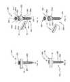
- FIG. 8is a side view of a rod bender device for use with the spinal stabilization system of FIG. 1 ;
- FIG. 9is a side cross-sectional view of the area of detail indicated in FIG. 8 ;
- FIG. 10is a perspective view of a pair of rod bender devices of FIG. 8 having the connecting rod of FIG. 4 inserted therethrough;
- FIG. 11is a perspective view of the pair of rod bender devices of FIG. 8 having the connecting rod of FIG. 4 inserted therethrough in a different orientation;
- FIG. 12is a side view of a spinal stabilization system in accordance with another embodiment of the present disclosure.
- FIG. 13is an exploded perspective view of the spinal stabilization system of FIG. 12 with parts separated;
- FIG. 14is a side view of the spinal stabilization system of FIG. 12 illustrating a placement of a connecting rod in a different orientation
- FIG. 15is an exploded perspective view of the spinal stabilization system of FIG. 14 ;
- FIG. 16is an end view of a spinal stabilization system in accordance with yet another embodiment of the present disclosure.
- FIG. 17is an exploded perspective view of the spinal stabilization system of FIG. 16 ;
- FIG. 18is an end view of the spinal stabilization system of FIG. 16 after a reduction of a connecting rod;
- FIG. 19is a side view of the spinal stabilization system of FIG. 16 with a loading unit detached from a bone screw;
- FIG. 20is an end view of the spinal stabilization system of FIG. 19 .
- distalwill refer to that portion of the instrument, apparatus, device or component thereof which is farther from the user while, the term “proximal,” will refer to that portion of the instrument, apparatus, device or component thereof which is closer to the user.
- proximalwill refer to that portion of the instrument, apparatus, device or component thereof which is closer to the user.
- cephaladis used in this application to indicate a direction toward a patient's head, while the term “caudad” indicates a direction toward the patient's feet.
- the term “medial”indicates a direction toward the middle of the body of the patient
- the term “lateral”indicates a direction toward a side of the body of the patient, i.e., away from the middle of the body of the patient.
- the term “posterior”indicates a direction toward the patient's back
- the term “anterior”indicates a direction toward the patient's front.
- Spinal stabilization system 100includes at least one bone screw 50 and a connecting rod 10 .
- Connecting rod 10is configured and dimensioned to be selectively and releasably secured to bone screw 50 .
- Connecting rod 10is defined by an elongate body of a particular length.
- the elongate bodyis made of a biocompatible material such as Titanium (Ti—CP) and its alloys (e.g., Ti-6Al-4V), Cobalt-Chrome Alloy (CoCr), or Stainless Steel (SS).
- the elongate body of connecting rod 10includes an elongate rounded section 12 having a substantially circular cross-section, an elongate head portion 14 , and a neck portion 16 that connects and transitions elongate rounded section 12 into elongate head portion 14 , thereby providing reduced stress concentration along the elongate body of connecting rod 10 .
- Neck portion 16may define a pair of concave sides joining elongate head portion 14 to elongate rounded section 12 .
- the elongate body of connecting rod 10may be monolithically formed as a unitary construct. For example, connecting rod 10 may be machined from a single piece of bar stock.
- elongate head portion 14has a non-circular cross-section. As shown, elongate head portion 14 has a substantially rectangular cross-section having suitable dimensions of, for example, about 6 mm ⁇ about 1 mm (0.246 in. ⁇ 0.039 in.). However, it is envisioned that elongate head portion 14 may have a cross-section that is substantially square, elliptical or any other shape to add rigidity to rounded section 12 of connecting rod 10 .
- elongate rounded section 12 of connecting rod 10is configured and dimensioned to be received in a slot 53 defined in a head portion 52 of bone screw 50 , as will be described in detail hereinbelow. While elongate head portion 14 of connector rod 10 is disposed above elongate rounded section 12 , elongate head portion 14 does not appreciably increase the height profile of the screw-rod combination. Connecting rod 10 affords greater strength and rigidity in comparison with ordinary circular rods with comparable dimensions. As such, connecting rod 10 and bone screw 50 construct affords greater rigidity and strength without increased bulk and profile.
- bone screw 50includes a head portion 52 configured to receive connecting rod 10 therein, a shank 54 extending longitudinally from head portion 52 , and a set screw 60 threadably coupled to head portion 52 to secure connecting rod 10 in a slot 53 defined in head portion 52 .
- Head portion 52 of bone screw 50includes a pair of radially opposing walls 56 defining slot 53 therebetween.
- Radially opposing walls 56include internal threads 57 configured for engaging external threads of set screw 60 .
- Slot 53defines a substantially U-shape channel configured and dimensioned to receive connecting rod 10 .
- Slot 53includes a leading end portion 53 a and a trailing end portion 53 b ( FIG. 2 ).
- leading end portion 53 ahas an arcuate configuration configured to accommodate a circular cross-section of rounded section 12 of connecting rod 10 .
- Trailing end portion 53 b of slot 53includes a pair of opposing guide members 51 ( FIG. 3 ) defining an aperture 51 a configured and dimensioned to receive set screw 60 therethrough.
- the pair of opposing guide members 51includes a lip 51 b extending radially inward and defining an acute angle with respect to trailing end portion 53 b of slot 53 to facilitate centering and/or insertion of set screw 60 within aperture 51 a .
- the pair of opposing guide members 51inhibits flexing of the pair of radially opposing walls 56 defining slot 53 therebetween.
- connecting rod 10is securely positioned in slot 53 defined between the pair of radially opposing walls 56 .
- connecting rod 10is inserted into slot 53 through a lateral opening 53 c defined in a lateral side of head portion 52 of bone screw 50 .
- trailing end portion 53 b of slot 53defines a substantially planar surface such that set screw 60 threadably inserted in slot 53 is substantially flush with trailing end portions 56 b of the respective walls 56 when connecting rod 10 is positioned within slot 53 and secured by set screw 60 therein.
- shank 54includes threads 55 for engagement through vertebral bodies.
- Bone screw 50may be made of a biocompatible material such as Titanium (Ti—CP) and its alloys (e.g., Ti-6Al-4V), Cobalt-Chrome Alloy (CoCr) or Stainless Steel (SS).
- Ti—CPTitanium
- CrCobalt-Chrome Alloy
- SSStainless Steel
- head portion 52 and shank 54may be monolithically formed.
- spinal stabilization system 100may further include rod bender devices 80 .
- Each rod bender devices 80define matching apertures 88 configured to receive and hold at least a portion of connecting rod 10 therein.
- Rod bender device 80includes a handle member 82 , an elongate body 84 extending distally from handle portion 82 , and an engaging portion 86 coupled to elongate body 84 .
- Elongate body 84is coupled or formed with handle member 82 and engaging portion 86 so as to reduce stress concentration.
- Handle member 82may contain scalloped sections to facilitate gripping by the user.
- Elongate body 84may have a rectangular cross-section and may define a cavity along the length thereof to reduce the weight of device.
- Engaging portion 86defines at least one aperture 88 adapted and dimensioned to receive therethrough connecting rod 10 .
- inner walls that define aperture 88are configured to permit insertion of connecting rod 10 through aperture 88 in a single orientation with respect to such aperture.
- Each aperture 88includes an arcuate end wall 88 a configured to engage elongate rounded section 12 of connecting rod 10 , an opposite substantially straight end wall 88 b configured to engage the substantially flat portion of elongate head portion 14 of connecting rod 10 , and connecting side walls 88 c connecting arcuate end wall 88 a and the substantially straight end wall 88 b .
- connecting rod 10is inserted into each aperture 88 in a single orientation.
- a plurality of apertures 88are defined in engaging portion 86 in different orientations, as shown in FIGS. 10 and 11 .
- connecting rod 10may be inserted in non-corresponding apertures 88 in rod bender devices 80 to facilitate twisting of connecting rod 10 , if necessary or desired.
- elongate body 84may be tailored to meet the needs of the surgical application to provide a suitable long moment arm necessary to provide the user a mechanical advantage to bend connecting rod 10 .
- elongate body 84may be a hollow tubular member and/or define lightening holes to reduce the weight of device 80 .
- Threaded shank 54can be driven into the desired vertebral body by providing torsional force via a driving tool (not shown) configured to mate with and grip bone screw 50 .
- driving toolnot shown
- connecting rod 10is positioned within slot 53 of head portion 52 .
- spinal stabilization system 100can be utilized to correct spinal deformity.
- the surgeonPrior to securing connecting rod 10 with bone screw 50 , the surgeon can manipulate and correct the curve of the spinal column, i.e., to manually manipulate and reduce the “rib hump.” After placing the spine in proper position, the surgeon can bend connecting rod 10 prior to securing connecting rod 10 to the first two points of the spinal column where the construct is to be attached.
- connecting rod 10by utilizing the pair of rod bender devices 80 .
- connecting rod 10is inserted through apertures 88 of rod bender devices 80 and force is applied at handle members 82 of rod bender devices 80 to appropriately contour and shape connecting rod 10 to a desired curve.
- connecting rod 10is positioned in respective slots 53 of bone screws 50 implanted in vertebral bodies.
- Set screws 60can now be threadably inserted into head portion 52 of bone screw 50 .
- the rod and bone screw combination of the present disclosuremay provide particular advantages in, e.g., scoliosis or other spinal deformity surgery, in which high stress levels are exerted upon such constructs at particular levels in the construct or over the entire length of such a construct.
- Spinal stabilization system 200includes at least one bone screw 250 and a connecting rod 10 .
- Connecting rod 10is configured and dimensioned to be selectively and releasably secured to bone screw 250 .
- Connecting rod 10is defined by an elongate body of a particular length.
- the elongate bodyis made of a biocompatible material such as Titanium (Ti—CP) and its alloys (e.g., Ti-6Al-4V), Cobalt-Chrome Alloy (CoCr), or Stainless Steel (SS).
- bone screw 250includes a head portion 252 configured to receive connecting rod 10 therein, a shank 254 extending longitudinally from head portion 252 , and a set screw 260 threadably coupled to head portion 252 to secure connecting rod 10 in a slot 253 defined in head portion 252 .
- Head portion 252 of bone screw 250includes a pair of opposing leading and trailing walls 256 a , 256 b defining slot 253 therebetween.
- trailing wall 256 bdefines an aperture 251 a configured and dimensioned to receive a set screw 260 therethrough.
- Trailing wall 256 bincludes a lip 251 extending radially inward to facilitate centering and/or insertion of set screw 60 within aperture 251 a .
- an inner surface 251 b of lip 251includes threads 251 c configured to engage external threads of set screw 260 .
- Slot 253defines a substantially U-shaped channel configured and dimensioned to receive connecting rod 10 therein.
- the U-shaped channelis rotated 90 degrees, whereby the U-shape channel of slot 253 is substantially orthogonal to a longitudinal axis “L-L” ( FIG. 12 ) defined by bone screw 250 .
- Slot 253includes an arcuate portion 253 a configured and dimensioned to accommodate a circular cross-section of rounded section 12 of connecting rod 10 .
- inner sides of leading and trailing walls 256 a , 256 b that define slot 253are substantially flat to provide a planar contact with elongate head portion 14 of connecting rod 10 . Under such a configuration, once connecting rod 10 is disposed within slot 253 , elongate head portion 14 of connecting rod 10 engages one or both of leading and trailing walls 256 a , 256 b to inhibit movement and rotation within slot 253 .
- slot 253is dimensioned such that when connecting rod 10 is positioned within slot 253 , as shown, elongate head portion 14 of connecting rod 10 engages inner side of trailing wall 256 b . Under such a configuration, flexing of trailing wall 256 b is substantially eliminated, and thereby further securing connecting rod 10 with bone screw 250 . It is further contemplated that connecting rod 10 may be positioned in slot 253 such that elongate rounded section 12 of connecting rod 10 engages arcuate portion 253 a of slot 253 , as shown in FIGS. 14 and 15 .
- Slot 253is configured and dimensioned such that when connecting rod 10 is oriented in such a manner, elongate head portion 14 engages inner surfaces of leading and trailing walls 256 a , 256 b . Under such a configuration, rotation and movement of connecting rod 10 in slot 253 is reduced. Moreover, such a configuration further eliminates flexing of trailing wall 256 when connecting rod 10 is positioned within slot 253 .
- shank 254includes threads 255 for engagement through vertebral bodies.
- Bone screw 250may be made of a biocompatible material such as Titanium (Ti—CP) and its alloys (e.g., Ti-6Al-4V), Cobalt-Chrome Alloy (CoCr) or Stainless Steel (SS).
- head portion 252 and shank 254may be monolithically formed.
- the method of using spinal stabilization system 200is substantially similar to the method of using spinal stabilization system 100 , described hereinabove, and thus will not be discussed herein.
- Spinal stabilization system 300includes at least one bone screw 350 , a loading unit 400 , and a connecting rod 10 .
- Connecting rod 10is configured and dimensioned to be selectively and releasably secured to bone screw 350 .
- Bone screw 350includes a head portion 352 configured to receive connecting rod 10 therein, a shank 354 extending longitudinally from head portion 352 , and a set screw 60 threadably coupled to head portion 352 to secure connecting rod 10 in a slot 353 defined in head portion 352 .
- Head portion 352 of bone screw 350includes a pair of radially opposing walls 356 defining slot 353 therebetween.
- Radially opposing walls 356include internal threads 357 configured for engaging external threads of set screw 60 .
- Slot 353defines a substantially U-shape channel configured and dimensioned to receive connecting rod 10 .
- Slot 353is aligned with a longitudinal axis “Z-Z” ( FIG. 16 ) defined by shank 354 of bone screw 350 .
- Slot 353includes a leading end portion 353 a and a trailing end portion 353 b ( FIG. 20 ).
- leading end portion 353 ahas an arcuate configuration configured to accommodate a circular cross-section of rounded section 12 of connecting rod 10 .
- Trailing end portion 353 b of slot 53defines a substantially planar surface such that set screw 60 threadably inserted in slot 353 is substantially flush with trailing end portions 356 b ( FIG. 20 ) of the respective walls 356 when connecting rod 10 is positioned within slot 353 and secured by set screw 60 therein, as shown in FIG. 20 .
- a loading unit 400is integrally formed with bone screw 350 .
- Loading unit 400includes a pair of opposing walls 402 , 404 defining a slot 453 ( FIG. 18 ) therebetween.
- Slot 453is configured and dimensioned to receive set screw 60 .
- Slot 453is in communication with slot 353 of bone screw 350 .
- slot 453 of loading unit 400is substantially aligned with slot 353 .
- inner walls of the pair of opposing walls 402 , 404include threads to engage external threads on set screw 60 .
- Loading unit 400includes weakened regions 410 configured to facilitate detachment of loading unit 400 from head portion 352 of bone screw 350 .
- slot 453is configured and dimensioned to provide a friction fit engagement with connecting rod 10 . In this manner, connecting rod 10 may be retained in any position along slot 453 of loading unit 400 .
- connecting rod 10is positioned in slot 453 of loading unit 400 , as shown in FIG. 16 .
- the cliniciandoes not have to place connecting rod 10 and set screw 60 with bone screw 350 in-situ.
- Set screw 60threadably engages threads of inner sides of opposing walls 402 , 404 .
- set screw 60 and connecting rod 10 positioned in slot 453 of loading unit 400are lowered by rotating set screw 60 , which urges connecting rod 10 towards a seat of slot 353 until elongate rounded section 12 of connecting rod 10 is in contact with leading end portion 353 a of slot 353 .
- a top surface of set screw 60is flush with weakened region 410 of loading unit 400 .
- the clinicianmay detach loading unit 400 from head portion 352 of bone screw 350 by, e.g., cutting through weakened region 410 using a surgical knife (not shown), as shown in FIGS. 19 and 20 .
- a surgical knifenot shown
- repeated bending of walls 402 , 404 towards and away from central longitudinal axis “Z-Z” of screw 350causes separation of walls 402 , 404 from loading unit 400 along weakened region 410 .
- Shank 354includes threads 355 for engagement through vertebral bodies.
- Bone screw 50may be made of a biocompatible material such as Titanium (Ti—CP) and its alloys (e.g., Ti-6Al-4V), Cobalt-Chrome Alloy (CoCr) or Stainless Steel (SS).
- Ti—CPTitanium
- CoCrCobalt-Chrome Alloy
- SSStainless Steel
- head portion 52 and shank 54may be monolithically formed.
- the method of using spinal stabilization system 300is substantially similar to the method of using spinal stabilization system 100 , described hereinabove, and thus will not be discussed herein.
Landscapes
- Health & Medical Sciences (AREA)
- Orthopedic Medicine & Surgery (AREA)
- Surgery (AREA)
- Life Sciences & Earth Sciences (AREA)
- Neurology (AREA)
- Medical Informatics (AREA)
- Biomedical Technology (AREA)
- Heart & Thoracic Surgery (AREA)
- Engineering & Computer Science (AREA)
- Molecular Biology (AREA)
- Animal Behavior & Ethology (AREA)
- General Health & Medical Sciences (AREA)
- Public Health (AREA)
- Veterinary Medicine (AREA)
- Nuclear Medicine, Radiotherapy & Molecular Imaging (AREA)
- Surgical Instruments (AREA)
- Prostheses (AREA)
Abstract
Description
Claims (7)
Priority Applications (2)
| Application Number | Priority Date | Filing Date | Title |
|---|---|---|---|
| US13/675,189US9827018B2 (en) | 2012-11-13 | 2012-11-13 | Spinal stabilization system |
| US15/795,929US10813670B2 (en) | 2012-11-13 | 2017-10-27 | Spinal stabilization system |
Applications Claiming Priority (1)
| Application Number | Priority Date | Filing Date | Title |
|---|---|---|---|
| US13/675,189US9827018B2 (en) | 2012-11-13 | 2012-11-13 | Spinal stabilization system |
Related Child Applications (1)
| Application Number | Title | Priority Date | Filing Date |
|---|---|---|---|
| US15/795,929DivisionUS10813670B2 (en) | 2012-11-13 | 2017-10-27 | Spinal stabilization system |
Publications (2)
| Publication Number | Publication Date |
|---|---|
| US20140135844A1 US20140135844A1 (en) | 2014-05-15 |
| US9827018B2true US9827018B2 (en) | 2017-11-28 |
Family
ID=50682429
Family Applications (2)
| Application Number | Title | Priority Date | Filing Date |
|---|---|---|---|
| US13/675,189Active2034-12-18US9827018B2 (en) | 2012-11-13 | 2012-11-13 | Spinal stabilization system |
| US15/795,929Active2032-11-21US10813670B2 (en) | 2012-11-13 | 2017-10-27 | Spinal stabilization system |
Family Applications After (1)
| Application Number | Title | Priority Date | Filing Date |
|---|---|---|---|
| US15/795,929Active2032-11-21US10813670B2 (en) | 2012-11-13 | 2017-10-27 | Spinal stabilization system |
Country Status (1)
| Country | Link |
|---|---|
| US (2) | US9827018B2 (en) |
Cited By (2)
| Publication number | Priority date | Publication date | Assignee | Title |
|---|---|---|---|---|
| US10813670B2 (en) | 2012-11-13 | 2020-10-27 | K2M, Inc. | Spinal stabilization system |
| US20230240724A1 (en)* | 2019-05-22 | 2023-08-03 | Nuvasive, Inc. | Posterior spinal fixation screws |
Families Citing this family (7)
| Publication number | Priority date | Publication date | Assignee | Title |
|---|---|---|---|---|
| WO2012006064A1 (en)* | 2010-06-28 | 2012-01-12 | K2M, Inc. | Spinal stabilization system |
| US9968408B1 (en) | 2013-03-15 | 2018-05-15 | Nuvasive, Inc. | Spinal balance assessment |
| US9421038B2 (en) | 2013-12-06 | 2016-08-23 | K2M, Inc. | Spinal stabilization system including shaped spinal rod |
| US10695099B2 (en) | 2015-02-13 | 2020-06-30 | Nuvasive, Inc. | Systems and methods for planning, performing, and assessing spinal correction during surgery |
| WO2017151949A1 (en) | 2016-03-02 | 2017-09-08 | Nuvasive, Inc. | Systems and methods for spinal correction surgical planning |
| US11090096B2 (en) | 2016-04-12 | 2021-08-17 | K2M, Inc. | Surgical rod bender |
| US11426213B1 (en)* | 2021-07-08 | 2022-08-30 | Bret Michael Berry | Vertebral fixation assembly |
Citations (33)
| Publication number | Priority date | Publication date | Assignee | Title |
|---|---|---|---|---|
| US5217497A (en) | 1990-07-04 | 1993-06-08 | Mehdian Seyed M H | Apparatus for use in the treatment of spinal disorders |
| US5261912A (en) | 1990-08-21 | 1993-11-16 | Synthes (U.S.A.) | Implant for an osteosynthesis device, in particular for spinal column correction |
| US5591235A (en)* | 1995-03-15 | 1997-01-07 | Kuslich; Stephen D. | Spinal fixation device |
| US5658286A (en) | 1996-02-05 | 1997-08-19 | Sava; Garard A. | Fabrication of implantable bone fixation elements |
| US5667508A (en) | 1996-05-01 | 1997-09-16 | Fastenetix, Llc | Unitary locking cap for use with a pedicle screw |
| US5899904A (en) | 1998-10-19 | 1999-05-04 | Third Milennium Engineering, Llc | Compression locking vertebral body screw, staple, and rod assembly |
| US5910142A (en) | 1998-10-19 | 1999-06-08 | Bones Consulting, Llc | Polyaxial pedicle screw having a rod clamping split ferrule coupling element |
| US5947969A (en) | 1998-10-19 | 1999-09-07 | Third Millennium Engineering, Llc | Rotatable locking vertebral body screw, staple and rod assembly |
| US5989250A (en)* | 1996-10-24 | 1999-11-23 | Spinal Concepts, Inc. | Method and apparatus for spinal fixation |
| US6102912A (en) | 1997-05-29 | 2000-08-15 | Sofamor S.N.C. | Vertebral rod of constant section for spinal osteosynthesis instrumentations |
| US6451021B1 (en) | 2001-02-15 | 2002-09-17 | Third Millennium Engineering, Llc | Polyaxial pedicle screw having a rotating locking element |
| US20020161368A1 (en) | 1999-10-20 | 2002-10-31 | Foley Kevin T. | Instruments and methods for stabilization of bony structures |
| US6482207B1 (en) | 2000-07-13 | 2002-11-19 | Fastenetix, Llc | Efficient assembling modular locking pedicle screw |
| US6540749B2 (en) | 2001-02-17 | 2003-04-01 | Bernd Schäfer | Bone screw |
| US6582434B2 (en) | 2000-05-10 | 2003-06-24 | Showa Ika Kohgyo Co., Ltd. | Vertebral connecting rod and spinal osteosynthesis device using the same |
| US6595992B1 (en)* | 1996-10-24 | 2003-07-22 | Spinal Concepts, Inc. | Method and apparatus for spinal fixation |
| US6644087B1 (en) | 2002-07-26 | 2003-11-11 | Third Millennium Engineering, Llc | Rod bender for bending surgical rods |
| US20050065515A1 (en) | 2003-09-24 | 2005-03-24 | Tae-Ahn Jahng | Marking and guidance method and system for flexible fixation of a spine |
| US20050273099A1 (en)* | 2002-10-07 | 2005-12-08 | Christian Baccelli | Plate fixing system |
| US20080086130A1 (en)* | 2006-10-06 | 2008-04-10 | Depuy Spine, Inc. | Torsionally stable fixation |
| US20090048632A1 (en)* | 2005-10-22 | 2009-02-19 | Paul Firkins | Spinal Support Rod Kit |
| US20090088800A1 (en)* | 2007-08-24 | 2009-04-02 | Spinal Elements, Inc. | Loop rod spinal stablization device |
| US7520879B2 (en) | 2006-02-07 | 2009-04-21 | Warsaw Orthopedic, Inc. | Surgical instruments and techniques for percutaneous placement of spinal stabilization elements |
| US7563274B2 (en)* | 2006-04-25 | 2009-07-21 | Warsaw Orthopedic, Inc. | Surgical instruments and techniques for controlling spinal motion segments with positioning of spinal stabilization elements |
| US7569061B2 (en) | 2004-11-16 | 2009-08-04 | Innovative Spinal Technologies, Inc. | Off-axis anchor guidance system |
| US20090198279A1 (en)* | 2008-02-02 | 2009-08-06 | Texas Scottish Rite Hospital For Children | Spinal Rod Link Reducer |
| US7588588B2 (en) | 2003-10-21 | 2009-09-15 | Innovative Spinal Technologies | System and method for stabilizing of internal structures |
| US7588575B2 (en) | 2003-10-21 | 2009-09-15 | Innovative Spinal Technologies | Extension for use with stabilization systems for internal structures |
| US7604653B2 (en)* | 2003-04-25 | 2009-10-20 | Kitchen Michael S | Spinal curvature correction device |
| US20100063544A1 (en)* | 2008-09-10 | 2010-03-11 | Butler Michael S | Spinal Rod |
| US7766942B2 (en)* | 2006-08-31 | 2010-08-03 | Warsaw Orthopedic, Inc. | Polymer rods for spinal applications |
| US7931676B2 (en) | 2007-01-18 | 2011-04-26 | Warsaw Orthopedic, Inc. | Vertebral stabilizer |
| US20110190823A1 (en)* | 2007-11-28 | 2011-08-04 | Zimmer Spine, Inc. | Stabilization system and method |
Family Cites Families (7)
| Publication number | Priority date | Publication date | Assignee | Title |
|---|---|---|---|---|
| FR2823095B1 (en)* | 2001-04-06 | 2004-02-06 | Ldr Medical | RACHIS OSTEOSYNTHESIS DEVICE AND PLACEMENT METHOD |
| FR2833151B1 (en)* | 2001-12-12 | 2004-09-17 | Ldr Medical | BONE ANCHORING IMPLANT WITH POLYAXIAL HEAD |
| US7674277B2 (en)* | 2004-12-01 | 2010-03-09 | Warsaw Orthopedic, Inc. | Side-loading bone anchor |
| US8182513B2 (en)* | 2005-11-24 | 2012-05-22 | Lanx, S.R.L. | Modular vertebral stabilizer |
| US7951173B2 (en)* | 2007-05-16 | 2011-05-31 | Ortho Innovations, Llc | Pedicle screw implant system |
| WO2012006064A1 (en) | 2010-06-28 | 2012-01-12 | K2M, Inc. | Spinal stabilization system |
| US9827018B2 (en) | 2012-11-13 | 2017-11-28 | K2M, Inc. | Spinal stabilization system |
- 2012
- 2012-11-13USUS13/675,189patent/US9827018B2/enactiveActive
- 2017
- 2017-10-27USUS15/795,929patent/US10813670B2/enactiveActive
Patent Citations (35)
| Publication number | Priority date | Publication date | Assignee | Title |
|---|---|---|---|---|
| US5217497A (en) | 1990-07-04 | 1993-06-08 | Mehdian Seyed M H | Apparatus for use in the treatment of spinal disorders |
| US5261912A (en) | 1990-08-21 | 1993-11-16 | Synthes (U.S.A.) | Implant for an osteosynthesis device, in particular for spinal column correction |
| US5591235A (en)* | 1995-03-15 | 1997-01-07 | Kuslich; Stephen D. | Spinal fixation device |
| US5658286A (en) | 1996-02-05 | 1997-08-19 | Sava; Garard A. | Fabrication of implantable bone fixation elements |
| US5667508A (en) | 1996-05-01 | 1997-09-16 | Fastenetix, Llc | Unitary locking cap for use with a pedicle screw |
| US5989250A (en)* | 1996-10-24 | 1999-11-23 | Spinal Concepts, Inc. | Method and apparatus for spinal fixation |
| US6595992B1 (en)* | 1996-10-24 | 2003-07-22 | Spinal Concepts, Inc. | Method and apparatus for spinal fixation |
| US6102912A (en) | 1997-05-29 | 2000-08-15 | Sofamor S.N.C. | Vertebral rod of constant section for spinal osteosynthesis instrumentations |
| US5910142A (en) | 1998-10-19 | 1999-06-08 | Bones Consulting, Llc | Polyaxial pedicle screw having a rod clamping split ferrule coupling element |
| US5947969A (en) | 1998-10-19 | 1999-09-07 | Third Millennium Engineering, Llc | Rotatable locking vertebral body screw, staple and rod assembly |
| US5899904A (en) | 1998-10-19 | 1999-05-04 | Third Milennium Engineering, Llc | Compression locking vertebral body screw, staple, and rod assembly |
| US20020161368A1 (en) | 1999-10-20 | 2002-10-31 | Foley Kevin T. | Instruments and methods for stabilization of bony structures |
| US6582434B2 (en) | 2000-05-10 | 2003-06-24 | Showa Ika Kohgyo Co., Ltd. | Vertebral connecting rod and spinal osteosynthesis device using the same |
| US6482207B1 (en) | 2000-07-13 | 2002-11-19 | Fastenetix, Llc | Efficient assembling modular locking pedicle screw |
| US6451021B1 (en) | 2001-02-15 | 2002-09-17 | Third Millennium Engineering, Llc | Polyaxial pedicle screw having a rotating locking element |
| US6540749B2 (en) | 2001-02-17 | 2003-04-01 | Bernd Schäfer | Bone screw |
| US6644087B1 (en) | 2002-07-26 | 2003-11-11 | Third Millennium Engineering, Llc | Rod bender for bending surgical rods |
| US7503918B2 (en) | 2002-10-07 | 2009-03-17 | Abbott Spine | Plate fixing system |
| US20050273099A1 (en)* | 2002-10-07 | 2005-12-08 | Christian Baccelli | Plate fixing system |
| US7604653B2 (en)* | 2003-04-25 | 2009-10-20 | Kitchen Michael S | Spinal curvature correction device |
| US20050065515A1 (en) | 2003-09-24 | 2005-03-24 | Tae-Ahn Jahng | Marking and guidance method and system for flexible fixation of a spine |
| US7588588B2 (en) | 2003-10-21 | 2009-09-15 | Innovative Spinal Technologies | System and method for stabilizing of internal structures |
| US7618442B2 (en) | 2003-10-21 | 2009-11-17 | Theken Spine, Llc | Implant assembly and method for use in an internal structure stabilization system |
| US7588575B2 (en) | 2003-10-21 | 2009-09-15 | Innovative Spinal Technologies | Extension for use with stabilization systems for internal structures |
| US7569061B2 (en) | 2004-11-16 | 2009-08-04 | Innovative Spinal Technologies, Inc. | Off-axis anchor guidance system |
| US20090048632A1 (en)* | 2005-10-22 | 2009-02-19 | Paul Firkins | Spinal Support Rod Kit |
| US7520879B2 (en) | 2006-02-07 | 2009-04-21 | Warsaw Orthopedic, Inc. | Surgical instruments and techniques for percutaneous placement of spinal stabilization elements |
| US7563274B2 (en)* | 2006-04-25 | 2009-07-21 | Warsaw Orthopedic, Inc. | Surgical instruments and techniques for controlling spinal motion segments with positioning of spinal stabilization elements |
| US7766942B2 (en)* | 2006-08-31 | 2010-08-03 | Warsaw Orthopedic, Inc. | Polymer rods for spinal applications |
| US20080086130A1 (en)* | 2006-10-06 | 2008-04-10 | Depuy Spine, Inc. | Torsionally stable fixation |
| US7931676B2 (en) | 2007-01-18 | 2011-04-26 | Warsaw Orthopedic, Inc. | Vertebral stabilizer |
| US20090088800A1 (en)* | 2007-08-24 | 2009-04-02 | Spinal Elements, Inc. | Loop rod spinal stablization device |
| US20110190823A1 (en)* | 2007-11-28 | 2011-08-04 | Zimmer Spine, Inc. | Stabilization system and method |
| US20090198279A1 (en)* | 2008-02-02 | 2009-08-06 | Texas Scottish Rite Hospital For Children | Spinal Rod Link Reducer |
| US20100063544A1 (en)* | 2008-09-10 | 2010-03-11 | Butler Michael S | Spinal Rod |
Cited By (2)
| Publication number | Priority date | Publication date | Assignee | Title |
|---|---|---|---|---|
| US10813670B2 (en) | 2012-11-13 | 2020-10-27 | K2M, Inc. | Spinal stabilization system |
| US20230240724A1 (en)* | 2019-05-22 | 2023-08-03 | Nuvasive, Inc. | Posterior spinal fixation screws |
Also Published As
| Publication number | Publication date |
|---|---|
| US10813670B2 (en) | 2020-10-27 |
| US20180049776A1 (en) | 2018-02-22 |
| US20140135844A1 (en) | 2014-05-15 |
Similar Documents
| Publication | Publication Date | Title |
|---|---|---|
| US10813670B2 (en) | Spinal stabilization system | |
| EP2584982B1 (en) | Spinal stabilization system | |
| AU2011291476B2 (en) | Spinal fixation system | |
| US9504497B2 (en) | Iliosacral polyaxial screw | |
| US9801662B2 (en) | Spinal stabilization system | |
| US9186182B2 (en) | Spinal stabilization system | |
| US10973552B2 (en) | Surgical system for bone screw insertion and rod reduction | |
| US9168068B2 (en) | Spinal stabilization system | |
| US9095378B2 (en) | Spinal stabilization system | |
| US20090292308A1 (en) | Spinal fixation system | |
| US9421038B2 (en) | Spinal stabilization system including shaped spinal rod | |
| US20170143385A1 (en) | Spinal rod reduction system | |
| US20210228241A1 (en) | Polyaxial Lateral Offset Connector | |
| US20120245693A1 (en) | Spinal fixation device | |
| AU2015203073B2 (en) | Spinal stabilization system | |
| AU2014200455B2 (en) | Spinal Fixation System |
Legal Events
| Date | Code | Title | Description |
|---|---|---|---|
| AS | Assignment | Owner name:K2M, INC., VIRGINIA Free format text:ASSIGNMENT OF ASSIGNORS INTEREST;ASSIGNORS:ARK, TIMMON;MEYER, ROBERT;BARRUS, MICHAEL;SIGNING DATES FROM 20121101 TO 20121105;REEL/FRAME:029286/0339 | |
| AS | Assignment | Owner name:SILICON VALLEY BANK, CALIFORNIA Free format text:FIRST AMENDMENT TO PATENT SECURITY AGREEMENT;ASSIGNORS:K2M, INC.;K2M UNLIMITED;K2M HOLDINGS, INC.;REEL/FRAME:034034/0097 Effective date:20141021 | |
| AS | Assignment | Owner name:SILICON VALLEY BANK, AS ADMINISTRATIVE AGENT, CALIFORNIA Free format text:SECOND AMENDMENT TO PATENT SECURITY AGREEMENT;ASSIGNORS:K2M, INC.;K2M HOLDINGS, INC.;K2M UK LIMITED;REEL/FRAME:037091/0221 Effective date:20151029 Owner name:SILICON VALLEY BANK, AS ADMINISTRATIVE AGENT, CALI Free format text:SECOND AMENDMENT TO PATENT SECURITY AGREEMENT;ASSIGNORS:K2M, INC.;K2M HOLDINGS, INC.;K2M UK LIMITED;REEL/FRAME:037091/0221 Effective date:20151029 | |
| FEPP | Fee payment procedure | Free format text:ENTITY STATUS SET TO UNDISCOUNTED (ORIGINAL EVENT CODE: BIG.) | |
| STCF | Information on status: patent grant | Free format text:PATENTED CASE | |
| AS | Assignment | Owner name:K2M HOLDINGS, INC., VIRGINIA Free format text:RELEASE BY SECURED PARTY;ASSIGNOR:SILICON VALLEY BANK;REEL/FRAME:047496/0001 Effective date:20181109 Owner name:K2M UK LIMITED, UNITED KINGDOM Free format text:RELEASE BY SECURED PARTY;ASSIGNOR:SILICON VALLEY BANK;REEL/FRAME:047496/0001 Effective date:20181109 Owner name:K2M, INC., VIRGINIA Free format text:RELEASE BY SECURED PARTY;ASSIGNOR:SILICON VALLEY BANK;REEL/FRAME:047496/0001 Effective date:20181109 | |
| MAFP | Maintenance fee payment | Free format text:PAYMENT OF MAINTENANCE FEE, 4TH YEAR, LARGE ENTITY (ORIGINAL EVENT CODE: M1551); ENTITY STATUS OF PATENT OWNER: LARGE ENTITY Year of fee payment:4 | |
| AS | Assignment | Owner name:STRYKER CORPORATION, MICHIGAN Free format text:ASSIGNMENT OF ASSIGNORS INTEREST;ASSIGNOR:K2M, INC.;REEL/FRAME:071271/0170 Effective date:20250328 | |
| AS | Assignment | Owner name:VB SPINE US OPCO LLC, DELAWARE Free format text:ASSIGNMENT OF ASSIGNORS INTEREST;ASSIGNOR:STRYKER CORPORATION;REEL/FRAME:071312/0356 Effective date:20250505 | |
| MAFP | Maintenance fee payment | Free format text:PAYMENT OF MAINTENANCE FEE, 8TH YEAR, LARGE ENTITY (ORIGINAL EVENT CODE: M1552); ENTITY STATUS OF PATENT OWNER: LARGE ENTITY Year of fee payment:8 | |
| AS | Assignment | Owner name:ANKURA TRUST COMPANY, LLC, AS COLLATERAL AGENT, CONNECTICUT Free format text:PATENT SECURITY AGREEMENT;ASSIGNORS:K2M, INC.;VB SPINE US OPCO LLC;VB SPINE LLC;REEL/FRAME:071682/0116 Effective date:20250616 |