US9827009B2 - Atraumatic arthroscopic instrument sheath - Google Patents
Atraumatic arthroscopic instrument sheathDownload PDFInfo
- Publication number
- US9827009B2 US9827009B2US14/944,083US201514944083AUS9827009B2US 9827009 B2US9827009 B2US 9827009B2US 201514944083 AUS201514944083 AUS 201514944083AUS 9827009 B2US9827009 B2US 9827009B2
- Authority
- US
- United States
- Prior art keywords
- sheath
- tube
- inflow
- outflow
- diameter
- Prior art date
- Legal status (The legal status is an assumption and is not a legal conclusion. Google has not performed a legal analysis and makes no representation as to the accuracy of the status listed.)
- Expired - Lifetime, expires
Links
Images


Classifications
- A—HUMAN NECESSITIES
- A61—MEDICAL OR VETERINARY SCIENCE; HYGIENE
- A61B—DIAGNOSIS; SURGERY; IDENTIFICATION
- A61B17/00—Surgical instruments, devices or methods
- A61B17/32—Surgical cutting instruments
- A61B17/320016—Endoscopic cutting instruments, e.g. arthroscopes, resectoscopes
- A—HUMAN NECESSITIES
- A61—MEDICAL OR VETERINARY SCIENCE; HYGIENE
- A61B—DIAGNOSIS; SURGERY; IDENTIFICATION
- A61B1/00—Instruments for performing medical examinations of the interior of cavities or tubes of the body by visual or photographical inspection, e.g. endoscopes; Illuminating arrangements therefor
- A61B1/00131—Accessories for endoscopes
- A61B1/00135—Oversleeves mounted on the endoscope prior to insertion
- A—HUMAN NECESSITIES
- A61—MEDICAL OR VETERINARY SCIENCE; HYGIENE
- A61B—DIAGNOSIS; SURGERY; IDENTIFICATION
- A61B1/00—Instruments for performing medical examinations of the interior of cavities or tubes of the body by visual or photographical inspection, e.g. endoscopes; Illuminating arrangements therefor
- A61B1/00147—Holding or positioning arrangements
- A61B1/00154—Holding or positioning arrangements using guiding arrangements for insertion
- A—HUMAN NECESSITIES
- A61—MEDICAL OR VETERINARY SCIENCE; HYGIENE
- A61B—DIAGNOSIS; SURGERY; IDENTIFICATION
- A61B1/00—Instruments for performing medical examinations of the interior of cavities or tubes of the body by visual or photographical inspection, e.g. endoscopes; Illuminating arrangements therefor
- A61B1/012—Instruments for performing medical examinations of the interior of cavities or tubes of the body by visual or photographical inspection, e.g. endoscopes; Illuminating arrangements therefor characterised by internal passages or accessories therefor
- A61B1/015—Control of fluid supply or evacuation
- A—HUMAN NECESSITIES
- A61—MEDICAL OR VETERINARY SCIENCE; HYGIENE
- A61B—DIAGNOSIS; SURGERY; IDENTIFICATION
- A61B1/00—Instruments for performing medical examinations of the interior of cavities or tubes of the body by visual or photographical inspection, e.g. endoscopes; Illuminating arrangements therefor
- A61B1/313—Instruments for performing medical examinations of the interior of cavities or tubes of the body by visual or photographical inspection, e.g. endoscopes; Illuminating arrangements therefor for introducing through surgical openings, e.g. laparoscopes
- A61B1/317—Instruments for performing medical examinations of the interior of cavities or tubes of the body by visual or photographical inspection, e.g. endoscopes; Illuminating arrangements therefor for introducing through surgical openings, e.g. laparoscopes for bones or joints, e.g. osteoscopes, arthroscopes
- A—HUMAN NECESSITIES
- A61—MEDICAL OR VETERINARY SCIENCE; HYGIENE
- A61B—DIAGNOSIS; SURGERY; IDENTIFICATION
- A61B17/00—Surgical instruments, devices or methods
- A61B17/02—Surgical instruments, devices or methods for holding wounds open, e.g. retractors; Tractors
- A61B17/0218—Surgical instruments, devices or methods for holding wounds open, e.g. retractors; Tractors for minimally invasive surgery
- A—HUMAN NECESSITIES
- A61—MEDICAL OR VETERINARY SCIENCE; HYGIENE
- A61B—DIAGNOSIS; SURGERY; IDENTIFICATION
- A61B17/00—Surgical instruments, devices or methods
- A61B17/34—Trocars; Puncturing needles
- A61B17/3417—Details of tips or shafts, e.g. grooves, expandable, bendable; Multiple coaxial sliding cannulas, e.g. for dilating
- A61B17/3421—Cannulas
- A61B17/3423—Access ports, e.g. toroid shape introducers for instruments or hands
- A61M1/0084—
- A—HUMAN NECESSITIES
- A61—MEDICAL OR VETERINARY SCIENCE; HYGIENE
- A61M—DEVICES FOR INTRODUCING MEDIA INTO, OR ONTO, THE BODY; DEVICES FOR TRANSDUCING BODY MEDIA OR FOR TAKING MEDIA FROM THE BODY; DEVICES FOR PRODUCING OR ENDING SLEEP OR STUPOR
- A61M1/00—Suction or pumping devices for medical purposes; Devices for carrying-off, for treatment of, or for carrying-over, body-liquids; Drainage systems
- A61M1/84—Drainage tubes; Aspiration tips
- A61M1/85—Drainage tubes; Aspiration tips with gas or fluid supply means, e.g. for supplying rinsing fluids or anticoagulants
- A—HUMAN NECESSITIES
- A61—MEDICAL OR VETERINARY SCIENCE; HYGIENE
- A61B—DIAGNOSIS; SURGERY; IDENTIFICATION
- A61B17/00—Surgical instruments, devices or methods
- A61B17/32—Surgical cutting instruments
- A61B17/320068—Surgical cutting instruments using mechanical vibrations, e.g. ultrasonic
- A61B2017/320084—Irrigation sleeves
- A—HUMAN NECESSITIES
- A61—MEDICAL OR VETERINARY SCIENCE; HYGIENE
- A61B—DIAGNOSIS; SURGERY; IDENTIFICATION
- A61B90/00—Instruments, implements or accessories specially adapted for surgery or diagnosis and not covered by any of the groups A61B1/00 - A61B50/00, e.g. for luxation treatment or for protecting wound edges
- A61B90/30—Devices for illuminating a surgical field, the devices having an interrelation with other surgical devices or with a surgical procedure
- A61B2090/306—Devices for illuminating a surgical field, the devices having an interrelation with other surgical devices or with a surgical procedure using optical fibres
- A—HUMAN NECESSITIES
- A61—MEDICAL OR VETERINARY SCIENCE; HYGIENE
- A61B—DIAGNOSIS; SURGERY; IDENTIFICATION
- A61B2217/00—General characteristics of surgical instruments
- A61B2217/002—Auxiliary appliance
- A61B2217/005—Auxiliary appliance with suction drainage system
- A—HUMAN NECESSITIES
- A61—MEDICAL OR VETERINARY SCIENCE; HYGIENE
- A61B—DIAGNOSIS; SURGERY; IDENTIFICATION
- A61B2217/00—General characteristics of surgical instruments
- A61B2217/002—Auxiliary appliance
- A61B2217/007—Auxiliary appliance with irrigation system
- A—HUMAN NECESSITIES
- A61—MEDICAL OR VETERINARY SCIENCE; HYGIENE
- A61B—DIAGNOSIS; SURGERY; IDENTIFICATION
- A61B90/00—Instruments, implements or accessories specially adapted for surgery or diagnosis and not covered by any of the groups A61B1/00 - A61B50/00, e.g. for luxation treatment or for protecting wound edges
- A61B90/36—Image-producing devices or illumination devices not otherwise provided for
- A61B90/361—Image-producing devices, e.g. surgical cameras
Definitions
- the inventions described belowrelate to the field of arthroscopic surgical instruments.
- surgical instrumentssuch as trocars, cannulas, and optical medical devices, including endoscopes, cystoscopes, arthroscopes, laparoscopes, etc., are inserted through small incisions or portals in a patient's body or body cavity and manipulated to perform surgical procedures within the patient.
- Minimally invasive surgical proceduressuch as arthroscopy are safer than open surgery and result in quicker patient recovery, shorter hospital stays, and lower health care costs. Accordingly, minimizing invasiveness continues to be of importance, and there is a continuing need for devices and methods that achieve this objective.
- fluid channelseffectively add to the outer diameter of the instruments.
- known endoscopic instrumentsprovide inflow/outflow through an assembly of concentric sheaths that define channels for inflow and outflow of fluids to and from the operative or surgical site.
- the fluidmay be an irrigating solution that helps maintain a clear view of the site for the physician.
- Certain known irrigating systemsprovide simultaneous and continuous inflow and outflow. These systems are known as “continuous flow” systems.
- the known inflow and outflow endoscope systemsintroduce an irrigating fluid into the surgical site.
- the endoscopehas an inflow channel defined by the inner surface of the sheath.
- the fluidpasses through the channel and exits the distal end of the sheath to irrigate the operative site.
- Fluid at the surgical sitemay be withdrawn through an outflow channel defined by the outer surface of the inner sheath and the inner surface of a surrounding outer sheath.
- the outflow channeloriginates at the distal end (front end) of the instrument and transports fluid to an exit point at the proximal end of the outer sheath.
- the diameter of these systemsrequires larger surgical portals.
- Another barrier to minimally invasive surgeryis fluid management within the surgical site.
- fluidis pumped into the joint under pressure to maintain distention in the joint for visualization and hemostasis.
- a computerized pump that precisely monitors the flow rate and intra-articular pressureusually accomplishes this. Poor fluid management, however, can lead to complications. If pressure is set too low, excessive bleeding and poor visualization could occur. If the pressure is set too high and for too long, significant swelling in the surrounding tissue can occur. During arthroscopic knee surgery, excessively high pressure could result in compartment syndrome of the leg.
- the devices and methods shown belowprovide for smaller surgical portals during arthroscopy while also providing the management of substantially simultaneous inflow and outflow of fluid to the surgical site.
- the atraumatic inflow/outflow sheathallows a surgeon to drain fluids from or introduce fluids into the surgical field, thereby keeping the surgical field clear.
- the inflow/outflow sheathis a tube having inwardly extending ribs that form multiple lumens when the arthroscope is inserted.
- the proximal portion of the sheathis provided with fluid ports, a manifold and other means of controlling the flow of fluid inside the sheath.
- the distal portion of the inflow/outflow sheathis provided with a plurality of holes.
- the distal tip of the atraumatic inflow/outflow sheathis frustoconical in shape allowing a seal to be formed between the sheath and the outer surface of a surgical instrument when an instrument is inserted into the sheath and extends distally past the distal tip of the sheath.
- Each holecommunicates with one or more of the lumens inside the tube, thereby allowing fluid to flow between the surgical field and sources or sinks located outside the patient.
- the inflow/outflow sheaththereby allows the surgeon to maintain a clear surgical field and protect the patient from accidental injury while eliminating the need for a third irrigation instrument.
- the atraumatic inflow/outflow sheathmay be provided with a working channel to enable access of additional surgical instruments to a surgical site through the sheath.
- the sheathmay also be provided with pressure ports facilitating pressure measurements to be taken from the surgical site. These measurements are used to manage the inflow and outflow of fluids to the surgical site.
- the sheathmay also be provided with illumination ports for illuminating the surgical site in order to enhance imaging during surgery.
- FIG. 1shows a method of performing arthroscopic surgery on a patient.
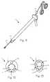
- FIG. 2shows an inflow/outflow atraumatic sheath for use with arthroscopic instruments.
- FIG. 3shows the distal portion of an atraumatic sheath and an arthroscope extending distally from the distal end of the sheath.
- FIG. 4shows the distal portion of an atraumatic sheath and an arthroscope extending distally from the distal end of the sheath.
- FIG. 5shows a cross section of the distal portion of an inflow/outflow atraumatic sheath.
- FIG. 6shows a cross section of the distal portion of an inflow/outflow atraumatic sheath.
- FIG. 7shows a cross section of the distal portion of an inflow/outflow atraumatic sheath.
- FIG. 8shows a cross section of the distal portion of an inflow/outflow atraumatic sheath.
- FIG. 9shows a cross section of the distal portion of an inflow/outflow atraumatic sheath.
- FIG. 10shows a cross section of the distal portion of an inflow/outflow atraumatic sheath.
- FIG. 11depicts an inflow/outflow atraumatic sheath with a working channel.
- FIG. 12shows the cross-section of an inflow/outflow atraumatic sheath with a working channel.
- FIG. 13shows the cross-section of an inflow/outflow atraumatic sheath with a working channel.
- FIG. 14depicts an inflow/outflow atraumatic sheath with a working channel and a reusable pressure sensor catheter.
- FIG. 15depicts an inflow/outflow sheath with a pressure sensing system.
- FIG. 16depicts an inflow/outflow sheath with a pressure sensing port.
- FIG. 17depicts a cross-section of an inflow/outflow sheath with a pressure sensing port.
- FIG. 18illustrates an inflow/outflow sheath with a pressure sensing port in use.
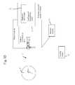
- FIG. 19depicts an inflow/outflow sheath with an illumination system.
- FIG. 20illustrates a cross-section of an inflow/outflow sheath with an illumination system.
- FIG. 1shows a method of performing arthroscopic surgery on a patient 1 by using an arthroscopic instrument such as an arthroscope 2 sheathed in an atraumatic sheath 3 .
- An arthroscopic instrumentmay be an arthroscope, endoscope, awl, pick, shaver, etc.
- the various parts of the arthroscopeare shown in phantom to indicate their positions inside the sheath.
- Various anatomical landmarks in the patient's knee 4are shown for reference, including the femur 5 , patella 6 , posterior cruciate ligament 7 , anterior cruciate ligament 8 , meniscus 9 , tibia 10 and fibula 11 .
- the surgeonintroduces the arthroscope 2 into the knee via a first incision 12 in order to visualize the surgical field.
- a trimming instrument 13is introduced through a second incision 14 to remove or trim tissue that the surgeon determines should be removed or trimmed.
- an irrigating instrumentmay be introduced through a third incision in order to irrigate the surgical field and thereby maintain a clear view.
- the irrigating instrumentmay be replaced by a combined arthroscope and inflow/outflow atraumatic sheath.
- the arthroscope 2is an optical instrument surrounded by a rigid cannula 17 having a distal edge that typically is cut at an angle. To protect the patient from unintended injury or trauma during the procedure, the arthroscope has been inserted into a resilient, outer introducer sheath or atraumatic sheath 3 that extends over the rigid cannula.
- FIG. 2illustrates the inflow/outflow atraumatic sheath 3 .
- the atraumatic sheath 3is a tube 22 with of a resilient material, such as a sterilizable polymer like soft plastic or rubber, characterized by a central lumen.
- the inner diameter of the atraumatic sheathis sized and dimensioned to closely fit over the outer diameter of an arthroscopic instrument 2 .
- the tube 22is characterized by a distal section 23 having a distal tip 19 and a proximal section.
- the distal tip of the atraumatic sheathis provided with a frustoconical shape and an opening 20 that is slightly smaller in diameter than the outer diameter of the distal tip of the arthroscope and/or the rigid cannula or other surgical instrument.
- the tipmay have an arcuate cross-section.
- the opening 20is provided in the atraumatic sheath so the surgeon may insert the endoscope 2 , or other surgical instruments, through the opening and into the surgical space.
- the distal section 23 of the sheathfurther comprises holes 25 or other openings that may be placed in fluid communication with a fluid source or vacuum source.
- the proximal section 21 of the atraumatic sheathis provided with a hub 24 manufactured from an elastomer to allow medical personnel to easily pull the atraumatic sheath over and secure the sheath to the rigid cannula, arthroscope 2 and/or arthroscopic instrument. Further, the hub 24 can be adapted for coupling to a fluid source 29 and/or a vacuum source 30 .
- the proximal section 21 of the atraumatic sheathmay also be provided with fittings, such as a locking hub or snap latches, that attach to fittings or openings disposed on the arthroscope or other instrument, thereby securing the atraumatic sheath.
- fittingssuch as a locking hub or snap latches
- the outer surface of the atraumatic sheath 3may be provided with a smooth coating to allow the arthroscope and rigid cannula to more easily move within an operating site.
- the sheathmay be provided with a Teflon® (PTFE or expanded polytetrafluoroethylene) coating or covered with a water-activated lubricant.
- the inner surface of the atraumatic sheath(the walls that define the lumen of the tube) may be provided with a non-slip coating or other high coefficient of friction coating.
- the inner surface of the atraumatic sheathmay be coated with a co-extruded tacky thermoplastic elastomer (TPE).
- TPEco-extruded tacky thermoplastic elastomer
- FIGS. 3 and 4show the distal section 23 of an inflow/outflow atraumatic sheath 3 and an arthroscope 2 extending distally from the distal tip 23 of the sheath 3 .
- the arthroscopemay then be extended distally out of the opening 20 and the surgical space visualized.
- FIG. 3shows the distal portion of an atraumatic sheath and an arthroscope extending distally from the distal end of the sheath 3 .
- Holes 25are provided in the distal portion of the sheath.
- the holes 25communicate with one or more lumens in the sheath.
- the lumen or lumenscommunicate with a vacuum source, fluid source, therapeutic agent source or a combination of sources.
- the holes 25provide for the inflow and outflow of fluids during a procedure.
- the tube 22 of the sheath and the distal tip 23are manufactured from the same flexible sterilizable polymer.
- the distal tip 23 of the inflow/outflow atraumatic sheathcan be made of an elastic material having a higher modulus of elasticity than the modulus of elasticity found in the material of the proximal portion of the sheath.
- the distal tip of the sheathhas an inner diameter that is slightly smaller than the outer diameter of most arthroscopes.
- the sheath 3When the sheath 3 is in use, a user inserts the arthroscope into the sheath 3 .
- the distal tipexpands 23 as the distal end of the arthroscope 2 slides past the distal tip of the sheath. Because the inner diameter of the tip 23 is less than the outer diameter of the arthroscope 2 , the tip will form a seal with the outer surface of the arthroscope 2 .
- FIG. 4shows the distal portion of an atraumatic sheath 3 and an arthroscope 2 extending distally from the distal tip 23 of the sheath.
- Holes 25are provided in the sheath to allow the inflow and outflow of fluids during a surgical procedure.
- a slit 36is provided in the tip and may extend into the distal section of the sheath. In use, the slit and tip expand as a user slides an arthroscope through the tip. Thus, the slit allows the sheath to accommodate larger arthroscopes or other medical instruments.
- FIGS. 5-10illustrate cross-sectional views of various configurations of the inflow/outflow atraumatic sheath.
- FIG. 5shows a cross-sectional view of the inflow/outflow sheath 3 using the inner surface 38 of the outer wall 39 of the tube 22 with the outer surface 40 of the arthroscope 2 to form inflow and outflow outer lumens.
- Relatively stiff ribs 41extending radially from the inner surface 38 of the outer wall 39 and running longitudinally along the sheath 3 form a seal with the outer surface 40 of the arthroscope, thereby creating the four outer lumens 42 , 43 , 44 , and 45 .
- the ends of the ribsmay be provided with elastic flanges 37 or extensions to enhance the seal made between the ribs 41 and the arthroscope 2 . This configuration reduces the overall size of the combined inflow/outflow sheath and arthroscope.
- the arthroscope 2is inserted into the sheath 3 through the central lumen 49 .
- the arthroscope 2may or may not be covered by a secondary protective sheath prior to insertion.
- the outer surface 40 of the arthroscope 2comes in contact with the flanges or extensions of the ribs 41 .
- a raised distinct tract, also referred to as a land,may also be used to contact the outer surface of the arthroscope 2 when the ribs 41 do not have flanges or extensions.
- the force of the outer surface 40 of the arthroscope 2 pushing against the ribs 41 and the rib flanges or rib extensionsforms a seal between the ribs 41 and the outer surface 40 of the arthroscope 2 .
- Outer lumens 42 , 43 , 44 , and 45are created by the ribs, the outer surface of the endoscope 40 , and inner surface 38 of the outer wall 39 of the inflow/outflow sheath.
- the ribsact as longitudinal struts that prevent the sheath from collapsing as they support the sheath under compression.
- the ribsreduce the unsupported span of the thin outer wall in the traverse axis, further preventing the collapse of the sheath.
- the seals formed by the contact between the ribs 41 and the outer surface 40 of the arthroscopeprevent fluids from flowing between the outer lumens 42 , 43 , 44 , and 45 .
- the outer lumens 42 , 43 , 44 , and 45facilitate the substantially continuous inflow and outflow of fluids to and from a surgical site through the holes 25 in the sheath.
- Check valves or gatesmay also be coupled to the inner surface 38 of the inflow/outflow sheath within the outer lumens 42 , 43 , 44 , and 45 to prevent outflow fluids from flowing back towards the surgical site and to prevent inflow fluids from flowing out the proximal end of the sheath.
- the inflow/outflow sheath 3 depicted in FIG. 5typically has an outer diameter measuring about 5 to 8 millimeters when the sheath is manufactured for use with arthroscopic instruments in larger joints, though this size may vary depending on the diameter of the arthroscopic instrument.
- the sheath 3has an outer diameter measuring about 2 to 5 millimeters.
- the outer wall 39 thickness of the inflow/outflow sheath 3is typically 1 millimeter or less depending on the extrusion and material comprising the tube.
- the inflow/outflow sheath 3can fit a range of arthroscopes +/ ⁇ 10% of the sheath's nominal diameter.
- the ribs 41extend from the inner surface of the inflow/outflow sheath inwardly and make a tight fit when the arthroscope is inserted, or hold the arthroscope concentrically in the sheath.
- a smaller outer diameter inflow/outflow sheath 3is particularly useful in arthroscopic surgery. Due to the unique configuration, the inflow/outflow sheath 3 is able to achieve a 30% reduction in diameter when compared to multi-lumen cannula devices requiring an inner wall of a cannula contacting the outer wall of the arthroscope.
- arthroscopic surgical techniquesuse a standard three-incision technique. A first incision is made and used to insert an inflow cannula to distend the joint. The inflow cannula is used to fill the joint with a sterile fluid to expand the joint and make room for the surgeon to see and work. A second incision is made in the patient and used to insert an arthroscope to view the surgical site.
- a third incisionis created by the surgeon to insert a specialized surgical instrument to correct the injury or abnormality.
- the jointis washed out with a stream of fluid, the instruments are removed, and the portals are closed with stitches, staples, or Steri-strips.
- surgeonshave begun to shift to a two-incision technique during arthroscopic surgery. Surgeons use one incision for inserting the arthroscope and a second incision for inserting the specialized surgical instrument. This technique eliminates a third portal by using an arthroscope with an inflow and outflow sheath.
- Sheaths currently used for inflow and outflowdo not, however, facilitate the continuous and simultaneous inflow and outflow of fluids to and from a surgical site with a sheath having a reduced diameter.
- Present sheathsonly facilitate alternating inflow and outflow of fluids to the surgical site and these sheaths are of a larger diameter requiring the incision to be larger.
- the Applicant's inflow/outflow sheath 3can facilitate the substantially simultaneous flow of fluids to and from a surgical site through the outer lumens 42 , 43 , 44 , and 45 while requiring a smaller size incision. Substantially simultaneous inflow and outflow allows the surgeon to keep the surgical site clean and the field of view clear.
- a unique feature of the Applicant's inflow/outflow sheath 3is the allowance of outflow to exceed inflow in the sheath 3 .
- Higher outflow capacityfacilitates the removal of debris and bodily fluids from the surgical site.
- Fluid pressure supplied to the inflow/outflow sheath 3is usually standard arthroscopic distension pressure at a pressure head of approximately 6 feet to 8 feet of water, but this may vary depending on the surgical application.
- Suction for use with the inflow/outflow sheath 3ranges from approximately 0 to 250 mm/Hg depending on the sheath size and surgical application.
- the inflow of fluid to a surgical sitecan be performed at the rate of 800 ml/min at 6 feet of water while outflow from the surgical site can be accomplished at the rate of 850 ml/min at 21 mm/Hg suction.
- the higher outflow capacityis able to remove both the irrigation fluid and the additional debris and bodily fluid coming from the patient during surgery.
- FIG. 6shows an inflow/outflow atraumatic sheath 3 similar to that shown in FIG. 5 .
- the relatively hard ribs 41are pleated, but still form a seal with the outer wall of the arthroscope 2 , thereby forming the lumens 42 , 43 , 44 , and 45 once the arthroscope is inserted into the sheath.
- the sheath of FIG. 6accommodates a variety of sizes of arthroscopes because the pleated ribs will bend to a degree necessary to accommodate larger sizes of arthroscopes, as shown in FIG. 7 .
- FIG. 8shows an inflow/outflow atraumatic sheath 3 similar to that shown in FIG. 6 .
- the ribs 41 of this sheathare elastic tubes that form a seal with the outer wall of the arthroscope 2 , thereby forming the outer lumens 42 , 43 , 44 , and 45 once the arthroscope is inserted into the sheath.
- the sheath of FIG. 8accommodates a variety of sizes of arthroscopes since the tubes will compress to a degree necessary to accommodate larger sizes of arthroscopes, as shown in FIG. 9 .
- FIG. 10shows a cross-section of an inflow/outflow atraumatic sheath 3 similar to that shown in FIG. 6 .
- the ribs 41 of this sheathare V-shaped and form a seal with the outer wall of the arthroscope 2 , thereby forming the outer lumens 42 , 43 , 44 , and 45 once the arthroscope is inserted into the sheath.
- the sheath of FIG. 10accommodates a variety of sizes of arthroscopes since the V-shaped ribs will compress to a degree necessary to accommodate larger sizes of arthroscopes.
- FIG. 11depicts an inflow/outflow atraumatic sheath 3 with a working channel 56 .
- a wire grasper 57is shown disposed within the working channel.
- the cross-section of an inflow/outflow atraumatic sheath with a working channelis shown in FIG. 12 .
- the atraumatic sheath 3comprises an outer wall 39 , a plurality of inward extending ribs 41 or flanges, and a working channel 56 disposed within the outer wall 39 .
- the working channelmay be disposed within a rib extending inwardly from an inner surface the outer wall that is sized and dimensioned to accommodate the working channel.
- the sheath 3is manufactured from a sterilizable polymer.
- the working channelis characterized by open proximal and distal ends and a lumen running longitudinally along the atraumatic sheath 3 .
- the proximal end of the working channelmay be coupled to an adapter 60 for guiding surgical instruments into the channel when the instrument are inserted. Further, the adapter may be used for coupling the sheath to surgical instruments.
- the outer wall 39 of the sheathis thicker in the area where the working channel is disposed.
- an arthroscopic instrumentsuch as an arthroscope is disposed within the sheath
- the inner surface 38 of the outer wall 39 of the tube 22 along with the outer surface 40 of the arthroscope 2 and the ribsform inflow and outflow outer lumens 42 and 43 .
- the working channel lumenis so sized and dimensioned as to facilitate the insertion of a surgical instrument into the working channel for use within a surgical site.
- the working channel 56may be sized and dimensioned to accommodate a variety of surgical instruments. These surgical instruments may include a therapeutic injection catheter for injecting medicinal solutions, an ablation probe, meniscal punch, suture anchor delivery device, tissue fixation device, rotating burr, a wire grasper/basket for loose body removal, a surgical stapler or a reusable pressure sensor catheter.
- surgical instrumentsmay include a therapeutic injection catheter for injecting medicinal solutions, an ablation probe, meniscal punch, suture anchor delivery device, tissue fixation device, rotating burr, a wire grasper/basket for loose body removal, a surgical stapler or a reusable pressure sensor catheter.
- the inflow/outflow atraumatic sheath 3may also be provided with a working channel 56 as depicted in FIG. 13 .
- the working channel 56is disposed within a raised and distinct tract such as a land 58 or rail having an arcuate cross-section and extending from the outer surface 59 of the outer wall of the atraumatic sheath.
- the land 58extends longitudinally along the sheath.
- Fluidsmay also be introduced to a surgical site directly through the working channel 56 .
- the working channel 56is coupled at the proximal end to a fluid source containing fluids such as fluent medications, biological agents, anesthetics, diagnostic dyes, solutions, tissue adhesives and cements, or other therapeutic agents. Fluent medications are injected from the fluid source in fluid communication with the working channel using a pump or syringe, through the working channel and into the site.
- FIG. 14depicts an inflow/outflow atraumatic sheath 3 with a working channel 56 and a reusable pressure sensor catheter 61 .
- the reusable pressure sensor catheter 61comprises an elongated shaft 62 sized and dimensioned to fit within the working channel 56 of the atraumatic sheath.
- the shaftis coupled to a transducer 63 and the transducer 63 is operably coupled to a control computer within an arthroscopy suction/irrigation pump.
- the reusable pressure sensor catheter 61When in use, the reusable pressure sensor catheter 61 is inserted into the working channel 56 of the inflow/outflow sheath. The sheath along with an arthroscopic instrument and reusable pressure sensor are then inserted into a surgical site.
- the shaft 62 of the pressure sensorallows the transducer 63 to be placed in fluid communication with the surgical site.
- the control computeris then able to take measurements from the transducer and determine the pressure at the surgical site.
- the pressure measurements takencan be displayed to a surgeon or technician and used by the control computer within the arthroscopy inflow/outflow pump to manage the inflow and outflow of fluid to the surgical site.
- FIGS. 15-17depict an inflow/outflow sheath with a pressure sensing system.
- the inflow/out sheathis provided with a pressure sensing port 66 .
- the pressure sensing port 66is characterized by a lumen extending longitudinally and disposed within the outer wall of the sheath 3 .
- the pressure sensing port lumenis disposed within a land 67 protruding inwardly from the inner surface of the outer wall of the sheath.
- the lumenis characterized by an open distal end and proximal end allowing fluid to enter the lumen.
- the lumenmay be characterized by the inner surface of the outer wall, the outer surface of the arthroscopic instrument, and ribs.
- the proximal end of the sheathfurther comprises an elastomeric hub 24 having a fitting 64 that is adapted for coupling the hub 24 to a pressure transducer 63 .
- the hub 24may be coupled to the transducer 63 through a snap fitting, compression fitting, flanged fitting, flangeless fitting, threaded fitting, or mechanical device suitable coupling components in a fluid system.
- the hubfurther comprises a fluid drain tube 70 for gravity draining of fluid from the surgical site or for coupling to a vacuum source for fluid removal from the surgical site.
- the transducer 63 in the pressure sensing systemis operably coupled to a control computer within an arthroscopy suction/irrigation pump. The transducer may be disposed anywhere between the pump and the sheath or may be disposed within the hub itself.
- the pressure sensing system having a transducer 63 and control computeris coupled to the inflow/outflow sheath.
- An arthroscopic instrumentsuch as an endoscope 2
- the outer surface 40 of the arthroscopic surgical instrumentis placed in contact with the ribs 41 and land 67 . This contact forms seals between the land and the outer surface 40 and the ribs 41 and the outer surface 40 .
- the outer surface 40 , inner surface 38 , ribs 41 , and land 67characterize outer lumens 42 and 43 .
- the sheath, along with an arthroscopic instrument 2 disposed therein,is then inserted through a portal 12 into a surgical site such as a knee 4 .
- the pressure sensing port in the sheathallows the transducer to be placed in fluid communication with the surgical site.
- the control computer 71 with feedback controlis then able to take measurements from the transducer and determine the pressure at the surgical site. Pressure measurements that are taken can be displayed to a surgeon or technician by a display 72 on the arthroscopy pump and can be used by the control computer within the arthroscopy inflow/outflow pump to manage the inflow and outflow of fluid to the surgical site. More fluid can be pumped into the surgical site or fluid may be removed by a vacuum source 30 or gravity drain 73 .
- FIGS. 19 and 20depict an inflow/outflow sheath 3 with an illumination system.
- the inflow/out flow sheath 3is provided with a one or more illumination ports 76 at the distal end of the sheath 3 .
- One or more optical fibers 77are disposed within a land 78 or rib 41 extending inwardly from the outer wall of the inflow outflow sheath.
- the optical fibersextend longitudinally along the sheath and are in optical communication with the illumination port and an illumination device.
- the illumination deviceis provided within the hub 24 coupled to the proximal section of the sheath.
- the illumination devicecomprises a circuit board and a plurality of Light Emitting Diodes (LED).
- LEDLight Emitting Diodes
- Photosensorsmay also be disposed in the illumination device when the sheath is for use with a surgical arthroscopic surgical instrument other than an arthroscope.
- a photosensoris an electric component that detects the presence of visible light, infrared transmission, and/or ultraviolet energy.
- Most photosensorscomprise a semiconductor having photoconductivity that allows the electrical conductance to vary depending on the intensity of the radiation striking the material.
- the optical fibersmay be coupled to an illumination device located outside the hub by an optical fiber connector coupled to the hub 24 .
- the LEDs in the illumination devicemay emit various wavelengths of light depending on the type of LED used. In some applications, an illumination device capable of emitting visible light may be used. In other applications, an illumination device emitting ultraviolet light may be used.
- the illumination deviceis in electrical communication with a power source such as a battery or power outlet.
- the illumination devicemay be coupled to a control computer 81 having image analysis software and hardware as well as a display for viewing and analyzing images from a surgical site.
- the endoscopeis coupled to a control computer having image analysis software and hardware as well as a display for viewing and analyzing images from a surgical site.
- the illumination device in the hubis coupled to a power source and control computer.
- the LEDs and/or the photosensors disposed within the housing of the illumination deviceare aligned with the optical fibers disposed within the outer wall, rib, or land of the inflow/outflow sheath. This alignment places the LED's and/or photosensors in optical communication with a surgical site through the illumination ports 76 when the sheath 3 is placed within a patient. Light from the LEDs is able to illuminate the surgical site.
- Optical sensors, when provided in the illumination devicecan be used for image analysis with a camera 80 and control computer.
- An arthroscopic instrumentsuch as an endoscope 2
- the outer surface 40 of the arthroscopic surgical instrumentis placed in contact with the ribs 41 and land 67 .
- This contactforms seals between the land and the outer surface 40 and one or more ribs 41 and the outer surface 40 .
- the outer surface 40 , inner surface 38 , one or more ribs 41 , and land 67characterize outer lumens 42 and 43 .
- the lumensare in fluid communication with a fluid source and/or a vacuum source and the surgical site through one or more holes 25 in the outer wall of the sheath.
- the holes in the sheathare slotted.
- the hub 24is be adapted for coupling to a fluid source 29 and/or a vacuum source 30 through a fluid manifold 82 coupled to the hub and in fluid communication with the outer lumens.
Landscapes
- Health & Medical Sciences (AREA)
- Life Sciences & Earth Sciences (AREA)
- Surgery (AREA)
- Heart & Thoracic Surgery (AREA)
- Public Health (AREA)
- Animal Behavior & Ethology (AREA)
- Biomedical Technology (AREA)
- Engineering & Computer Science (AREA)
- Veterinary Medicine (AREA)
- General Health & Medical Sciences (AREA)
- Medical Informatics (AREA)
- Molecular Biology (AREA)
- Nuclear Medicine, Radiotherapy & Molecular Imaging (AREA)
- Pathology (AREA)
- Radiology & Medical Imaging (AREA)
- Physics & Mathematics (AREA)
- Biophysics (AREA)
- Optics & Photonics (AREA)
- Orthopedic Medicine & Surgery (AREA)
- Physical Education & Sports Medicine (AREA)
- Oral & Maxillofacial Surgery (AREA)
- Pulmonology (AREA)
- Vascular Medicine (AREA)
- Anesthesiology (AREA)
- Hematology (AREA)
- Endoscopes (AREA)
- Surgical Instruments (AREA)
Abstract
Description
Claims (6)
Priority Applications (1)
| Application Number | Priority Date | Filing Date | Title |
|---|---|---|---|
| US14/944,083US9827009B2 (en) | 2004-01-29 | 2015-11-17 | Atraumatic arthroscopic instrument sheath |
Applications Claiming Priority (7)
| Application Number | Priority Date | Filing Date | Title |
|---|---|---|---|
| US10/769,629US7413542B2 (en) | 2004-01-29 | 2004-01-29 | Atraumatic arthroscopic instrument sheath |
| US11/016,274US7435214B2 (en) | 2004-01-29 | 2004-12-17 | Atraumatic arthroscopic instrument sheath |
| US11/094,626US7500947B2 (en) | 2004-01-29 | 2005-03-29 | Atraumatic arthroscopic instrument sheath |
| US12/401,451US8118731B2 (en) | 2004-01-29 | 2009-03-10 | Atraumatic arthroscopic instrument sheath |
| US13/401,500US8740773B2 (en) | 2004-01-29 | 2012-02-21 | Atraumatic arthroscopic instrument sheath |
| US14/294,612US9186044B2 (en) | 2004-01-29 | 2014-06-03 | Atraumatic arthroscopic instrument sheath |
| US14/944,083US9827009B2 (en) | 2004-01-29 | 2015-11-17 | Atraumatic arthroscopic instrument sheath |
Related Parent Applications (1)
| Application Number | Title | Priority Date | Filing Date |
|---|---|---|---|
| US14/294,612ContinuationUS9186044B2 (en) | 2004-01-29 | 2014-06-03 | Atraumatic arthroscopic instrument sheath |
Publications (2)
| Publication Number | Publication Date |
|---|---|
| US20160066950A1 US20160066950A1 (en) | 2016-03-10 |
| US9827009B2true US9827009B2 (en) | 2017-11-28 |
Family
ID=37054125
Family Applications (5)
| Application Number | Title | Priority Date | Filing Date |
|---|---|---|---|
| US11/094,626Expired - LifetimeUS7500947B2 (en) | 2004-01-29 | 2005-03-29 | Atraumatic arthroscopic instrument sheath |
| US12/401,451Expired - LifetimeUS8118731B2 (en) | 2004-01-29 | 2009-03-10 | Atraumatic arthroscopic instrument sheath |
| US13/401,500Expired - LifetimeUS8740773B2 (en) | 2004-01-29 | 2012-02-21 | Atraumatic arthroscopic instrument sheath |
| US14/294,612Expired - LifetimeUS9186044B2 (en) | 2004-01-29 | 2014-06-03 | Atraumatic arthroscopic instrument sheath |
| US14/944,083Expired - LifetimeUS9827009B2 (en) | 2004-01-29 | 2015-11-17 | Atraumatic arthroscopic instrument sheath |
Family Applications Before (4)
| Application Number | Title | Priority Date | Filing Date |
|---|---|---|---|
| US11/094,626Expired - LifetimeUS7500947B2 (en) | 2004-01-29 | 2005-03-29 | Atraumatic arthroscopic instrument sheath |
| US12/401,451Expired - LifetimeUS8118731B2 (en) | 2004-01-29 | 2009-03-10 | Atraumatic arthroscopic instrument sheath |
| US13/401,500Expired - LifetimeUS8740773B2 (en) | 2004-01-29 | 2012-02-21 | Atraumatic arthroscopic instrument sheath |
| US14/294,612Expired - LifetimeUS9186044B2 (en) | 2004-01-29 | 2014-06-03 | Atraumatic arthroscopic instrument sheath |
Country Status (4)
| Country | Link |
|---|---|
| US (5) | US7500947B2 (en) |
| EP (1) | EP1868489A4 (en) |
| JP (1) | JP5307534B2 (en) |
| WO (1) | WO2006105283A2 (en) |
Cited By (4)
| Publication number | Priority date | Publication date | Assignee | Title |
|---|---|---|---|---|
| USD974558S1 (en) | 2020-12-18 | 2023-01-03 | Stryker European Operations Limited | Ultrasonic knife |
| US12023059B2 (en) | 2018-02-02 | 2024-07-02 | Calyxo, Inc. | Devices and methods for minimally invasive kidney stone removal by combined aspiration and irrigation |
| US12256989B2 (en) | 2022-09-29 | 2025-03-25 | Calyxo, Inc. | Tool guiding device for kidney stone treatment apparatus |
| US12329399B2 (en) | 2022-03-02 | 2025-06-17 | Calyxo, Inc. | Kidney stone treatment system |
Families Citing this family (117)
| Publication number | Priority date | Publication date | Assignee | Title |
|---|---|---|---|---|
| NL1006944C2 (en) | 1997-09-04 | 1999-03-11 | Mark Hans Emanuel | Surgical endoscopic cutting device. |
| US7455666B2 (en) | 2001-07-13 | 2008-11-25 | Board Of Regents, The University Of Texas System | Methods and apparatuses for navigating the subarachnoid space |
| US10595710B2 (en)* | 2001-10-19 | 2020-03-24 | Visionscope Technologies Llc | Portable imaging system employing a miniature endoscope |
| US8038602B2 (en)* | 2001-10-19 | 2011-10-18 | Visionscope Llc | Portable imaging system employing a miniature endoscope |
| US6863651B2 (en) | 2001-10-19 | 2005-03-08 | Visionscope, Llc | Miniature endoscope with imaging fiber system |
| US20070167681A1 (en) | 2001-10-19 | 2007-07-19 | Gill Thomas J | Portable imaging system employing a miniature endoscope |
| US7226459B2 (en) | 2001-10-26 | 2007-06-05 | Smith & Nephew, Inc. | Reciprocating rotary arthroscopic surgical instrument |
| WO2005058207A1 (en) | 2003-12-11 | 2005-06-30 | Isto Technologies, Inc. | Particulate cartilage system |
| US8062214B2 (en) | 2004-08-27 | 2011-11-22 | Smith & Nephew, Inc. | Tissue resecting system |
| US20080255441A1 (en)* | 2004-12-01 | 2008-10-16 | Ron Hadani | Add-On For Invasive Probe |
| USD536790S1 (en)* | 2005-06-08 | 2007-02-13 | Karl Storz Gmbh & Co. Kg | Medical scope |
| WO2007025290A2 (en) | 2005-08-26 | 2007-03-01 | Isto Technologies, Inc. | Implants and methods for repair, replacement and treatment of joint disease |
| US9011328B2 (en) | 2005-10-18 | 2015-04-21 | Pneumoflex Systems, Llc | Oral-esophageal-gastric device with esophageal cuff to reduce gastric reflux and/or emesis |
| US9028406B2 (en) | 2005-10-18 | 2015-05-12 | Pneumoflex Systems, Llc | Oral-esophageal-gastric device to diagnose reflux and/or emesis |
| US8597184B2 (en) | 2005-10-18 | 2013-12-03 | Pneumoflex Systems, Llc | Techniques for evaluating urinary stress incontinence and use of involuntary reflex cough as a medical diagnostic tool |
| WO2007063904A1 (en)* | 2005-12-01 | 2007-06-07 | Olympus Medical Systems Corp. | Guiding long medical member and long medical device |
| US8394015B2 (en) | 2006-01-05 | 2013-03-12 | Children's Medical Center Corporation | Instrument port for minimally invasive cardiac surgery |
| US7503893B2 (en)* | 2006-02-03 | 2009-03-17 | Cannuflow, Inc. | Anti-extravasation sheath and method |
| US9814519B2 (en)* | 2006-04-20 | 2017-11-14 | Boston Scientific Scimed, Inc. | Ablation probe with ribbed insulated sheath |
| US8652090B2 (en)* | 2006-05-18 | 2014-02-18 | Cannuflow, Inc. | Anti-extravasation surgical portal plug |
| WO2008024290A2 (en)* | 2006-08-19 | 2008-02-28 | Fritsch Michael H | Devices and methods for in-vivo pathology diagnosis |
| US8357126B2 (en) | 2006-10-24 | 2013-01-22 | Cannuflow, Inc. | Anti-extravasation catheter |
| US8163549B2 (en) | 2006-12-20 | 2012-04-24 | Zimmer Orthobiologics, Inc. | Method of obtaining viable small tissue particles and use for tissue repair |
| USD583470S1 (en)* | 2007-04-12 | 2008-12-23 | Karl Storz Gmbh & Co. Kg | Medical instrument |
| US20090012629A1 (en) | 2007-04-12 | 2009-01-08 | Isto Technologies, Inc. | Compositions and methods for tissue repair |
| US7867190B2 (en)* | 2007-06-21 | 2011-01-11 | Sage Products, Inc. | Covered suction device |
| US8226548B2 (en)* | 2007-07-07 | 2012-07-24 | Cannuflow, Inc. | Rigid arthroscope system |
| DE202007009713U1 (en)* | 2007-07-10 | 2007-09-06 | Karl Storz Gmbh & Co. Kg | Surgical instrument system, has cam arranged on inner side of hollow shaft for reducing inner diameter of hollow shaft, where recess corresponding with cam is formed in shaft of medical shaft instrument |
| USD598099S1 (en)* | 2007-11-13 | 2009-08-11 | Karl Storz Gmbh & Co. Kg | Endoscope |
| WO2009152470A1 (en)* | 2008-06-13 | 2009-12-17 | The Foundry, Llc. | Methods and apparatus for joint distraction |
| US8267891B2 (en)* | 2008-12-18 | 2012-09-18 | Alcon Research, Ltd. | Gilled phacoemulsification irrigation sleeve |
| US12035902B2 (en) | 2009-03-17 | 2024-07-16 | Stryker Corporation | Method and apparatus for distracting a joint |
| USD630735S1 (en)* | 2009-09-29 | 2011-01-11 | Karl Storz Gmbh & Co. Kg | Medical device |
| US20110092955A1 (en)* | 2009-10-07 | 2011-04-21 | Purdy Phillip D | Pressure-Sensing Medical Devices, Systems and Methods, and Methods of Forming Medical Devices |
| GB0920938D0 (en)* | 2009-11-30 | 2010-01-13 | Imp Innovations Ltd | Steerable probes |
| US10376331B2 (en)* | 2010-02-12 | 2019-08-13 | Intuitive Surgical Operations, Inc. | Sheaths for jointed instruments |
| US9089351B2 (en)* | 2010-02-12 | 2015-07-28 | Intuitive Surgical Operations, Inc. | Sheath for surgical instrument |
| US9421032B2 (en)* | 2010-06-16 | 2016-08-23 | Covidien Lp | Seal port with blood collector |
| CN101889890A (en)* | 2010-06-21 | 2010-11-24 | 北京悬壶京琼医药科技发展研究院 | Periosteum stripper and fracture therapeutic equipment using same |
| US9138284B2 (en) | 2010-07-09 | 2015-09-22 | Intuitive Surgical Operations, Inc. | Electrosurgical tool cover |
| JP5844363B2 (en) | 2010-07-26 | 2016-01-13 | スティーラブル・インスツルメンツ・ベスローテン・フエンノートシャップ・メット・ベペルクテ・アーンスプラーケレイクヘイトSteerable Instruments Bvba | Kit including body invasive tube, and applicator package including the kit and applicator |
| EP2598015B1 (en) | 2010-07-26 | 2014-09-03 | Steerable Instruments B.V.B.A. | Endoscopic pressure detection assembly |
| JP5968886B2 (en)* | 2010-08-04 | 2016-08-10 | ミニマリー インべーシブ デバイシーズ, インコーポレイテッド | System and method for optimizing and maintaining operative field visualization while using a surgical microscope |
| US9155454B2 (en)* | 2010-09-28 | 2015-10-13 | Smith & Nephew, Inc. | Hysteroscopic system |
| US20120086791A1 (en)* | 2010-10-11 | 2012-04-12 | Yu Zheng | Endoscope and Angiograph System with Options for Advantages in Signal-to-Noise and Disposability |
| HK1198738A1 (en)* | 2011-05-03 | 2015-06-05 | Endosee股份有限公司 | Method and apparatus for hysteroscopy and endometrial biopsy |
| US20130303944A1 (en) | 2012-05-14 | 2013-11-14 | Intuitive Surgical Operations, Inc. | Off-axis electromagnetic sensor |
| US9452276B2 (en) | 2011-10-14 | 2016-09-27 | Intuitive Surgical Operations, Inc. | Catheter with removable vision probe |
| US20130096385A1 (en)* | 2011-10-14 | 2013-04-18 | Intuitive Surgical Operations, Inc. | Vision probe and catheter systems |
| US10238837B2 (en)* | 2011-10-14 | 2019-03-26 | Intuitive Surgical Operations, Inc. | Catheters with control modes for interchangeable probes |
| US9387048B2 (en) | 2011-10-14 | 2016-07-12 | Intuitive Surgical Operations, Inc. | Catheter sensor systems |
| EP2811919B1 (en)* | 2012-02-10 | 2020-09-09 | Merit Medical Systems, Inc. | Snare introducer |
| US8852091B2 (en) | 2012-04-04 | 2014-10-07 | Alcon Research, Ltd. | Devices, systems, and methods for pupil expansion |
| US9622646B2 (en) | 2012-06-25 | 2017-04-18 | Coopersurgical, Inc. | Low-cost instrument for endoscopically guided operative procedures |
| KR200465634Y1 (en) | 2012-08-06 | 2013-03-04 | 이영국 | Arthroscope with a derail controller |
| JP2015226556A (en)* | 2012-09-25 | 2015-12-17 | テルモ株式会社 | Medical device |
| US20140178343A1 (en) | 2012-12-21 | 2014-06-26 | Jian Q. Yao | Supports and methods for promoting integration of cartilage tissue explants |
| US9149294B2 (en) | 2013-01-24 | 2015-10-06 | Hybrid Cannula LP | Hybrid cannula and methods for manufacturing the same |
| US9119663B2 (en) | 2013-01-24 | 2015-09-01 | Hybrid Cannula LP | Hybrid cannula and methods for manufacturing the same |
| WO2014117023A1 (en)* | 2013-01-24 | 2014-07-31 | Arthrex, Inc. | Arthroscope sheath system with sensors |
| ES2738530T3 (en)* | 2013-02-25 | 2020-01-23 | Steris Instrument Man Services Inc | Rigid endoscope distal part |
| US20140276714A1 (en)* | 2013-03-15 | 2014-09-18 | Boston Scientific Scimed, Inc. | Active infusion sheath for ultrasound ablation catheter |
| RU2705046C2 (en) | 2013-04-01 | 2019-11-01 | Винод В. ПАТХИ | Lighting device |
| USD938095S1 (en) | 2013-04-01 | 2021-12-07 | Pathy Medical, Llc | Lighting device |
| EP3062867A4 (en)* | 2013-10-30 | 2017-08-02 | Faculty Physicians and Surgeons of Loma Linda University School of Medicine | Controlled pressure endoscopic and percutaneous surgery |
| USD743029S1 (en)* | 2014-03-11 | 2015-11-10 | Karl Storz Gmbh & Co. Kg | Endoscope |
| US20160278614A9 (en)* | 2014-04-02 | 2016-09-29 | Visionscope Technologies Llc | Devices and methods for minimally invasive arthroscopic surgery |
| CN106604687B (en)* | 2014-09-30 | 2019-08-16 | 莎·卡西玛尔·瓦拉巴达斯 | Sheath assembly and porous catheter for endoscopic surgery in different fields including suction, irrigation and material removal |
| US11096569B2 (en)* | 2014-10-15 | 2021-08-24 | Covidien Lp | Endoscope with a multiple diameter working section |
| DE102014118003A1 (en)* | 2014-12-05 | 2016-06-23 | Karl Storz Gmbh & Co. Kg | Endoscopic instrument and endoscopic instrument system |
| FR3031041B1 (en)* | 2014-12-26 | 2020-11-06 | Commissariat Energie Atomique | IMPLANTABLE OPTICAL BRAIN STIMULATION DEVICE INCLUDING A MULTI-CHANNEL CATHETER |
| WO2016122500A1 (en) | 2015-01-28 | 2016-08-04 | Smith & Nephew, Inc. | Tissue resection system |
| EP3261513B1 (en)* | 2015-02-27 | 2025-09-10 | Covidien LP | Oblique tip endoscope with zero degree field angle |
| CA2983341A1 (en)* | 2015-05-06 | 2016-11-10 | Rotation Medical, Inc. | Medical implant delivery system and related methods |
| EP3310241B1 (en) | 2015-06-17 | 2020-08-05 | Covidien LP | Endoscopic device with drip flange |
| WO2016205359A2 (en) | 2015-06-17 | 2016-12-22 | Smith & Nephew, Inc. | Surgical instrument with phase change cooling |
| AU2016277923B2 (en) | 2015-06-18 | 2021-02-25 | Covidien Lp | Surgical instrument with suction control |
| US10736491B2 (en)* | 2015-10-16 | 2020-08-11 | Corinth MedTech, Inc. | Surgical device and method of use |
| US10702305B2 (en) | 2016-03-23 | 2020-07-07 | Coopersurgical, Inc. | Operative cannulas and related methods |
| US10299803B2 (en) | 2016-08-04 | 2019-05-28 | Covidien Lp | Self-aligning drive coupler |
| CN106343943B (en)* | 2016-10-25 | 2017-12-01 | 上海凯利泰医疗科技股份有限公司 | A kind of joint lens device |
| EP4316389A3 (en) | 2017-01-19 | 2024-05-29 | Ohio State Innovation Foundation | Systems and methods for mechanical displacement of an esophagus |
| US10772654B2 (en) | 2017-03-02 | 2020-09-15 | Covidien Lp | Fluid-driven tissue resecting instruments, systems, and methods |
| WO2018180074A1 (en)* | 2017-03-27 | 2018-10-04 | オリンパス株式会社 | Insertion device and method for operating insertion device |
| US20180338673A1 (en)* | 2017-05-26 | 2018-11-29 | Covidien Lp | Surgical sheath and surgical apparatus including the same |
| EP4491133A3 (en) | 2017-07-25 | 2025-03-12 | Stryker European Operations Holdings LLC | Irrigation sleeves for use with surgical systems |
| US10888364B2 (en) | 2018-01-02 | 2021-01-12 | Medtronic Holding Company Sarl | Scoop cannula with deflectable wings |
| US11076920B2 (en)* | 2018-01-16 | 2021-08-03 | Microendoscopic Spine Institute, LLC | Instrumentation and surgical method for image-guided microendoscopic decompression |
| US11213316B2 (en) | 2018-03-09 | 2022-01-04 | The Children's Medical Center Corporation | Gasket with multi-leaflet valve for surgical port apparatus |
| US11284788B2 (en) | 2018-03-09 | 2022-03-29 | The Children's Medical Center Corporation | Instrument port with fluid flush system |
| US11324555B2 (en) | 2018-03-09 | 2022-05-10 | The Children's Medical Center Corporation | Instrument port including optical bulb secured to port body |
| US11547276B2 (en) | 2018-03-09 | 2023-01-10 | The Children's Medical Center Corporation | Optical bulb for surgical instrument port |
| CN109077780A (en)* | 2018-06-26 | 2018-12-25 | 陈克银 | A kind of needle knife mirror device for casting |
| US11540858B2 (en)* | 2018-10-17 | 2023-01-03 | University Of Louisville Research Foundation, Inc. | Multi-lumen arthroscopy cannula (MLAC) and methods of use |
| US11197710B2 (en) | 2018-10-26 | 2021-12-14 | Covidien Lp | Tissue resecting device including a blade lock and release mechanism |
| EP4230235A3 (en)* | 2018-12-20 | 2023-11-15 | Boston Scientific Scimed, Inc. | Flexible ureteroscope with debris suction availability |
| US10945752B2 (en) | 2019-03-20 | 2021-03-16 | Covidien Lp | Tissue resecting instrument including a rotation lock feature |
| US11883058B2 (en) | 2019-03-26 | 2024-01-30 | Covidien Lp | Jaw members, end effector assemblies, and ultrasonic surgical instruments including the same |
| CN113840578B (en) | 2019-05-29 | 2024-06-18 | 柯惠有限合伙公司 | Hysteroscopy system and method for managing patient bodily fluids |
| US11452806B2 (en) | 2019-10-04 | 2022-09-27 | Covidien Lp | Outflow collection vessels, systems, and components thereof for hysteroscopic surgical procedures |
| US11890237B2 (en) | 2019-10-04 | 2024-02-06 | Covidien Lp | Outflow collection vessels, systems, and components thereof for hysteroscopic surgical procedures |
| US20210128037A1 (en)* | 2019-10-30 | 2021-05-06 | Becton, Dickinson And Company | Blood collection system with user-adjusted pressure management and related methods |
| CN114727839A (en) | 2019-11-18 | 2022-07-08 | 瑟卡科学有限公司 | Device port for epicardial ablation with inflatable balloon |
| US11179172B2 (en) | 2019-12-05 | 2021-11-23 | Covidien Lp | Tissue resecting instrument |
| US11376032B2 (en) | 2019-12-05 | 2022-07-05 | Covidien Lp | Tissue resecting instrument |
| US11931070B1 (en) | 2020-01-30 | 2024-03-19 | Hybrid Cannula LP | Half pipe cannula and methods of manufacturing and using half pipe cannula |
| US11547782B2 (en) | 2020-01-31 | 2023-01-10 | Covidien Lp | Fluid collecting sheaths for endoscopic devices and systems |
| US11737777B2 (en) | 2020-02-05 | 2023-08-29 | Covidien Lp | Tissue resecting instruments |
| AU2021219111A1 (en)* | 2020-02-14 | 2022-10-06 | Fisher & Paykel Healthcare Limited | Directed gas flow accessory for providing gases to and venting gases from a patient |
| US11317947B2 (en) | 2020-02-18 | 2022-05-03 | Covidien Lp | Tissue resecting instrument |
| US11596429B2 (en) | 2020-04-20 | 2023-03-07 | Covidien Lp | Tissue resecting instrument |
| EP3970641B1 (en)* | 2020-09-17 | 2025-04-23 | Gyrus ACMI, Inc. d/b/a Olympus Surgical Technologies America | Endoscopic tip extender |
| US12156673B2 (en) | 2020-10-07 | 2024-12-03 | Covidien Lp | Temperature measurement device for a handpiece of a surgical instrument |
| US20220117577A1 (en)* | 2020-10-15 | 2022-04-21 | Elliot C. Schmidt | Stabilizing transnasal balloon sheath |
| US12364500B2 (en) | 2021-05-26 | 2025-07-22 | Covidien Lp | Tissue resecting instrument |
| WO2024224286A1 (en)* | 2023-04-27 | 2024-10-31 | Covidien Lp | Articulating endoscope with working channel |
| WO2025193726A1 (en)* | 2024-03-13 | 2025-09-18 | Arthrex, Inc. | Multi-lumen cannula and methods of using same |
Citations (15)
| Publication number | Priority date | Publication date | Assignee | Title |
|---|---|---|---|---|
| US4973321A (en)* | 1989-03-17 | 1990-11-27 | Michelson Gary K | Cannula for an arthroscope |
| US5449356A (en)* | 1991-10-18 | 1995-09-12 | Birtcher Medical Systems, Inc. | Multifunctional probe for minimally invasive surgery |
| US5575756A (en)* | 1993-08-16 | 1996-11-19 | Olympus Optical Co., Ltd. | Endoscope apparatus |
| US5601603A (en)* | 1993-06-16 | 1997-02-11 | White Spot Ag | Use of and process for the introduction of fibrin sealant into a puncture channel |
| US5637075A (en)* | 1994-04-25 | 1997-06-10 | Hamamatsu Ent Surgicenter | Apparatus for observing inside of body cavity |
| US5797882A (en)* | 1996-08-23 | 1998-08-25 | Becton Dickinson And Company | Arterial catheter and catheter/needle assembly with improved flow characteristics and method for its use |
| US6086542A (en)* | 1997-07-01 | 2000-07-11 | Linvatec Corporation | Pressure sensing input/output scope sheath |
| US20010056222A1 (en)* | 1999-02-18 | 2001-12-27 | Jurgen Rudischhauser | Endoscope |
| US6458076B1 (en)* | 2000-02-01 | 2002-10-01 | 5 Star Medical | Multi-lumen medical device |
| US20030004400A1 (en)* | 1999-10-14 | 2003-01-02 | Scimed Life Systems, Inc. | Endoscope and endoscopic instrument system having reduced backlash when moving the endoscopic instrument within a working channel of the endoscope |
| US6592544B1 (en)* | 1999-11-24 | 2003-07-15 | Edwards Lifesciences Corporation | Vascular access devices having hemostatic safety valve |
| US6878149B2 (en)* | 2002-03-25 | 2005-04-12 | Acueity, Inc. | Apparatus and method for intraductal abalation |
| US20050085695A1 (en)* | 2003-10-16 | 2005-04-21 | Cemal Shener | Endoscopic device |
| US20050203341A1 (en)* | 2004-03-15 | 2005-09-15 | Paradigm Optics, Incorporated | Polymer endoscopic shaft |
| US20060041186A1 (en)* | 2004-08-17 | 2006-02-23 | Vancaillie Thierry G | Continuous flow single sheath for endoscope |
Family Cites Families (67)
| Publication number | Priority date | Publication date | Assignee | Title |
|---|---|---|---|---|
| US4132227A (en)* | 1974-08-08 | 1979-01-02 | Winter & Ibe | Urological endoscope particularly resectoscope |
| US4491132A (en) | 1982-08-06 | 1985-01-01 | Zimmer, Inc. | Sheath and retractable surgical tool combination |
| SE442377B (en)* | 1984-06-29 | 1985-12-23 | Mediplast Ab | CATS, HEALTH OR SIMILAR DEVICE |
| US4646722A (en) | 1984-12-10 | 1987-03-03 | Opielab, Inc. | Protective endoscope sheath and method of installing same |
| DE3500444C2 (en)* | 1985-01-09 | 1986-10-16 | Aesculap-Werke Ag Vormals Jetter & Scheerer, 7200 Tuttlingen | Device for introducing an endoscope or a surgical tool into body cavities with a supply for a flushing medium and a suction device for this flushing medium |
| US4674500A (en) | 1985-09-27 | 1987-06-23 | Minnesota Mining And Manufacturing Company | Sheathed knife instrument |
| US4721097A (en) | 1986-10-31 | 1988-01-26 | Circon Corporation | Endoscope sheaths and method and apparatus for installation and removal |
| JPH0422721Y2 (en)* | 1986-11-29 | 1992-05-26 | ||
| US4820265A (en) | 1986-12-16 | 1989-04-11 | Minnesota Mining And Manufacturing Company | Tubing set |
| JP3167968B2 (en) | 1987-10-22 | 2001-05-21 | 北陸電気工業株式会社 | Manufacturing method of chip resistor |
| US4886049A (en) | 1988-05-17 | 1989-12-12 | Darras Robert L | Medical instrument cover |
| JP2535387B2 (en) | 1988-08-05 | 1996-09-18 | 富士通株式会社 | Optical position detector |
| US4897079A (en) | 1988-07-22 | 1990-01-30 | Allergan, Inc. | Polymeric sleeve for surgical instruments |
| JPH0641535Y2 (en) | 1988-09-22 | 1994-11-02 | 富士写真光機株式会社 | Internal diagnosis / treatment device |
| DE8814573U1 (en)* | 1988-11-18 | 1990-01-11 | BIOMET Deutschland GmbH, 14167 Berlin | endoscope |
| DE58905458D1 (en) | 1988-11-18 | 1993-10-07 | Effner Biomet Gmbh | Endoscope, especially arthroscope. |
| US4959058A (en)* | 1989-03-17 | 1990-09-25 | Michelson Gary K | Cannula having side opening |
| US5037386A (en)* | 1989-11-17 | 1991-08-06 | Minnesota Mining And Manufacturing Company | Pressure sensing scope cannula |
| JP2987452B2 (en)* | 1990-05-17 | 1999-12-06 | オリンパス光学工業株式会社 | Endoscope |
| GB9018390D0 (en) | 1990-08-22 | 1990-10-03 | Casale Enzo | Lavatory pan seat |
| US5386817A (en) | 1991-06-10 | 1995-02-07 | Endomedical Technologies, Inc. | Endoscope sheath and valve system |
| US5237984A (en) | 1991-06-24 | 1993-08-24 | Xomed-Treace Inc. | Sheath for endoscope |
| US5273545A (en) | 1991-10-15 | 1993-12-28 | Apple Medical Corporation | Endoscopic cannula with tricuspid leaf valve |
| WO1993011699A1 (en) | 1991-12-19 | 1993-06-24 | Meditron Devices, Inc. | Arthroscope having five functions |
| JP3660678B2 (en) | 1992-10-15 | 2005-06-15 | ザ ゼネラル ホスピタル コーポレーション | Infusion pump with electronically loadable drug library |
| US5337734A (en) | 1992-10-29 | 1994-08-16 | Advanced Polymers, Incorporated | Disposable sheath with optically transparent window formed continuously integral therewith |
| JPH0638902U (en)* | 1992-11-05 | 1994-05-24 | オリンパス光学工業株式会社 | Endoscope catheter |
| EP0600413A3 (en)* | 1992-11-30 | 1995-04-05 | Neuro Navigational Corp | Neuro endoscope for shunt. |
| US5527276A (en) | 1993-01-12 | 1996-06-18 | Arthroscopic Assistants, Inc. | Flexible inflow/outflow cannula |
| US5415157A (en) | 1993-02-05 | 1995-05-16 | Welcome; Steven | Damage preventing endoscope head cover |
| US5554098A (en) | 1993-02-26 | 1996-09-10 | Olympus Optical Co., Ltd. | Endoscope system including endoscope and disposable protection cover |
| US5575753A (en) | 1993-03-05 | 1996-11-19 | Olympus Optical Co., Ltd. | Endoscopic apparatus using a covered type endoscope fitted in an endoscope cover |
| JPH08500045A (en) | 1993-06-03 | 1996-01-09 | ゾーメッド トリース,インコーポレイテッド | Disposable endoscopic sheath |
| JPH08501720A (en) | 1993-07-22 | 1996-02-27 | ゾーメッド トリース,インコーポレイテッド | Disposable endoscopic sheath |
| US5643174A (en) | 1993-08-18 | 1997-07-01 | Sumitomo Bakelite Company Limited | Endoscopic guide tube with embedded coil spring |
| US5483951A (en) | 1994-02-25 | 1996-01-16 | Vision-Sciences, Inc. | Working channels for a disposable sheath for an endoscope |
| US5545150A (en) | 1994-05-06 | 1996-08-13 | Endoscopic Concepts, Inc. | Trocar |
| US5569183A (en) | 1994-06-01 | 1996-10-29 | Archimedes Surgical, Inc. | Method for performing surgery around a viewing space in the interior of the body |
| JP2802244B2 (en) | 1994-08-29 | 1998-09-24 | オリンパス光学工業株式会社 | Endoscope sheath |
| US5593394A (en)* | 1995-01-24 | 1997-01-14 | Kanesaka; Nozomu | Shaft for a catheter system |
| US5667068A (en) | 1995-06-13 | 1997-09-16 | Weaver; Stevie W. | Protective cover for an endoscope |
| US5571128A (en) | 1995-07-24 | 1996-11-05 | Shapiro; Henry | Safety surgical instrument |
| US6117068A (en) | 1995-10-19 | 2000-09-12 | Elite Genetics, Inc | Artificial insemination system |
| US6827710B1 (en)* | 1996-11-26 | 2004-12-07 | Edwards Lifesciences Corporation | Multiple lumen access device |
| US5779624A (en) | 1996-12-05 | 1998-07-14 | Boston Scientific Corporation | Sigmoid splint device for endoscopy |
| US5947990A (en) | 1997-02-24 | 1999-09-07 | Smith & Nephew, Inc. | Endoscopic surgical instrument |
| US6159160A (en)* | 1998-03-26 | 2000-12-12 | Ethicon, Inc. | System and method for controlled infusion and pressure monitoring |
| US5916145A (en) | 1998-08-07 | 1999-06-29 | Scimed Life Systems, Inc. | Device and method of using a surgical assembly with mesh sheath |
| US6126592A (en) | 1998-09-12 | 2000-10-03 | Smith & Nephew, Inc. | Endoscope cleaning and irrigation sheath |
| US6174280B1 (en) | 1998-11-19 | 2001-01-16 | Vision Sciences, Inc. | Sheath for protecting and altering the bending characteristics of a flexible endoscope |
| JP3448228B2 (en) | 1998-11-30 | 2003-09-22 | 富士写真光機株式会社 | Endoscope insertion guide tube |
| US6203537B1 (en) | 1999-02-04 | 2001-03-20 | Sorin Adrian | Laser-driven acoustic ablation catheter |
| US6447446B1 (en) | 1999-11-02 | 2002-09-10 | Medtronic Xomed, Inc. | Method and apparatus for cleaning an endoscope lens |
| GB9927338D0 (en) | 1999-11-18 | 2000-01-12 | Gyrus Medical Ltd | Electrosurgical system |
| US6808505B2 (en)* | 2000-02-01 | 2004-10-26 | Kadan Jeffrey S | Diagnostic needle arthroscopy and lavage system |
| US6585639B1 (en)* | 2000-10-27 | 2003-07-01 | Pulmonx | Sheath and method for reconfiguring lung viewing scope |
| US6712757B2 (en) | 2001-05-16 | 2004-03-30 | Stephen Becker | Endoscope sleeve and irrigation device |
| US20030018340A1 (en) | 2001-06-29 | 2003-01-23 | Branch Thomas P. | Method and apparatus for installing cannula |
| US6692431B2 (en) | 2001-09-07 | 2004-02-17 | Smith & Nephew, Inc. | Endoscopic system with a solid-state light source |
| US20030050603A1 (en) | 2001-09-12 | 2003-03-13 | Todd Erik F. | Cannula that provides bi-directional fluid flow that is regulated by a single valve |
| US20030083546A1 (en) | 2001-10-18 | 2003-05-01 | John Butler | Device |
| US7258120B2 (en)* | 2002-05-29 | 2007-08-21 | University Of Florida Research Foundation, Inc. | Endotracheal tube apparatus and method for using the same to reduce the risk of infections |
| JP2005033019A (en)* | 2003-07-04 | 2005-02-03 | Sumitomo Electric Ind Ltd | Light emitting module |
| US20050059963A1 (en)* | 2003-09-12 | 2005-03-17 | Scimed Life Systems, Inc. | Systems and method for creating transmural lesions |
| US7435214B2 (en)* | 2004-01-29 | 2008-10-14 | Cannuflow, Inc. | Atraumatic arthroscopic instrument sheath |
| WO2005072402A2 (en)* | 2004-01-29 | 2005-08-11 | Cannuflow, Inc. | Atraumatic arthroscopic instrument sheath |
| JP2008511341A (en) | 2004-05-28 | 2008-04-17 | ユー.エス. エンドスコピー グループ, インコーポレイテッド | Overtube assembly |
- 2005
- 2005-03-29USUS11/094,626patent/US7500947B2/ennot_activeExpired - Lifetime
- 2006
- 2006-03-29JPJP2008504350Apatent/JP5307534B2/enactiveActive
- 2006-03-29WOPCT/US2006/011621patent/WO2006105283A2/enactiveApplication Filing
- 2006-03-29EPEP06740032Apatent/EP1868489A4/ennot_activeWithdrawn
- 2009
- 2009-03-10USUS12/401,451patent/US8118731B2/ennot_activeExpired - Lifetime
- 2012
- 2012-02-21USUS13/401,500patent/US8740773B2/ennot_activeExpired - Lifetime
- 2014
- 2014-06-03USUS14/294,612patent/US9186044B2/ennot_activeExpired - Lifetime
- 2015
- 2015-11-17USUS14/944,083patent/US9827009B2/ennot_activeExpired - Lifetime
Patent Citations (18)
| Publication number | Priority date | Publication date | Assignee | Title |
|---|---|---|---|---|
| US4973321A (en)* | 1989-03-17 | 1990-11-27 | Michelson Gary K | Cannula for an arthroscope |
| US5449356A (en)* | 1991-10-18 | 1995-09-12 | Birtcher Medical Systems, Inc. | Multifunctional probe for minimally invasive surgery |
| US5601603A (en)* | 1993-06-16 | 1997-02-11 | White Spot Ag | Use of and process for the introduction of fibrin sealant into a puncture channel |
| US5575756A (en)* | 1993-08-16 | 1996-11-19 | Olympus Optical Co., Ltd. | Endoscope apparatus |
| US5637075A (en)* | 1994-04-25 | 1997-06-10 | Hamamatsu Ent Surgicenter | Apparatus for observing inside of body cavity |
| US5797882A (en)* | 1996-08-23 | 1998-08-25 | Becton Dickinson And Company | Arterial catheter and catheter/needle assembly with improved flow characteristics and method for its use |
| US6086542A (en)* | 1997-07-01 | 2000-07-11 | Linvatec Corporation | Pressure sensing input/output scope sheath |
| US20010056222A1 (en)* | 1999-02-18 | 2001-12-27 | Jurgen Rudischhauser | Endoscope |
| US6471639B2 (en)* | 1999-02-18 | 2002-10-29 | Karl Storz Gmbh & Co. Kg | Endoscope |
| US7033315B2 (en)* | 1999-10-14 | 2006-04-25 | Scimed Life Systems, Inc. | Endoscope and endoscopic instrument system having reduced backlash when moving the endoscopic instrument within a working channel of the endoscope |
| US20030004400A1 (en)* | 1999-10-14 | 2003-01-02 | Scimed Life Systems, Inc. | Endoscope and endoscopic instrument system having reduced backlash when moving the endoscopic instrument within a working channel of the endoscope |
| US6592544B1 (en)* | 1999-11-24 | 2003-07-15 | Edwards Lifesciences Corporation | Vascular access devices having hemostatic safety valve |
| US6458076B1 (en)* | 2000-02-01 | 2002-10-01 | 5 Star Medical | Multi-lumen medical device |
| US6878149B2 (en)* | 2002-03-25 | 2005-04-12 | Acueity, Inc. | Apparatus and method for intraductal abalation |
| US20050085695A1 (en)* | 2003-10-16 | 2005-04-21 | Cemal Shener | Endoscopic device |
| US7150713B2 (en)* | 2003-10-16 | 2006-12-19 | Smith & Nephew, Inc. | Endoscopic device |
| US20050203341A1 (en)* | 2004-03-15 | 2005-09-15 | Paradigm Optics, Incorporated | Polymer endoscopic shaft |
| US20060041186A1 (en)* | 2004-08-17 | 2006-02-23 | Vancaillie Thierry G | Continuous flow single sheath for endoscope |
Cited By (7)
| Publication number | Priority date | Publication date | Assignee | Title |
|---|---|---|---|---|
| US12023059B2 (en) | 2018-02-02 | 2024-07-02 | Calyxo, Inc. | Devices and methods for minimally invasive kidney stone removal by combined aspiration and irrigation |
| US12318099B2 (en) | 2018-02-02 | 2025-06-03 | Calyxo, Inc. | Devices and methods for minimally invasive kidney stone removal by combined aspiration and irrigation |
| USD974558S1 (en) | 2020-12-18 | 2023-01-03 | Stryker European Operations Limited | Ultrasonic knife |
| USD1045078S1 (en) | 2020-12-18 | 2024-10-01 | Stryker European Operations Limited | Ultrasonic knife |
| US12329399B2 (en) | 2022-03-02 | 2025-06-17 | Calyxo, Inc. | Kidney stone treatment system |
| US12329396B2 (en) | 2022-03-02 | 2025-06-17 | Calyxo, Inc. | Kidney stone treatment system |
| US12256989B2 (en) | 2022-09-29 | 2025-03-25 | Calyxo, Inc. | Tool guiding device for kidney stone treatment apparatus |
Also Published As
| Publication number | Publication date |
|---|---|
| US20090182201A1 (en) | 2009-07-16 |
| WO2006105283A3 (en) | 2007-12-27 |
| US20120215067A1 (en) | 2012-08-23 |
| US9186044B2 (en) | 2015-11-17 |
| US20160066950A1 (en) | 2016-03-10 |
| EP1868489A4 (en) | 2009-11-04 |
| WO2006105283A2 (en) | 2006-10-05 |
| EP1868489A2 (en) | 2007-12-26 |
| JP5307534B2 (en) | 2013-10-02 |
| US8740773B2 (en) | 2014-06-03 |
| US7500947B2 (en) | 2009-03-10 |
| US8118731B2 (en) | 2012-02-21 |
| JP2008535556A (en) | 2008-09-04 |
| US20050234298A1 (en) | 2005-10-20 |
| US20140350339A1 (en) | 2014-11-27 |
Similar Documents
| Publication | Publication Date | Title |
|---|---|---|
| US9827009B2 (en) | Atraumatic arthroscopic instrument sheath | |
| US9364204B2 (en) | Atraumatic arthroscopic instrument sheath | |
| US12226076B2 (en) | Rigid endoscope system | |
| US8123676B2 (en) | Anti-extravasation sheath | |
| US9872604B2 (en) | Atraumatic arthroscopic instrument sheath and method | |
| JP5025269B2 (en) | Noninvasive arthroscopy instrument sheath |
Legal Events
| Date | Code | Title | Description |
|---|---|---|---|
| AS | Assignment | Owner name:CANNUFLOW, INC., CALIFORNIA Free format text:ASSIGNMENT OF ASSIGNORS INTEREST;ASSIGNORS:KUCKLICK, THEODORE R.;TRIEB, MARTIN;REEL/FRAME:038094/0609 Effective date:20040805 | |
| STCF | Information on status: patent grant | Free format text:PATENTED CASE | |
| AS | Assignment | Owner name:PRISTINE SURGICAL LLC, NEW HAMPSHIRE Free format text:ASSIGNMENT OF ASSIGNORS INTEREST;ASSIGNOR:CANNUFLOW, INC.;REEL/FRAME:053594/0011 Effective date:20200611 | |
| MAFP | Maintenance fee payment | Free format text:PAYMENT OF MAINTENANCE FEE, 4TH YR, SMALL ENTITY (ORIGINAL EVENT CODE: M2551); ENTITY STATUS OF PATENT OWNER: SMALL ENTITY Year of fee payment:4 | |
| AS | Assignment | Owner name:PINEY LAKE OPPORTUNITIES ECI MASTER FUND LP, AS AGENT, CONNECTICUT Free format text:SECURITY INTEREST;ASSIGNOR:PRISTINE SURGICAL LLC;REEL/FRAME:056765/0708 Effective date:20210702 | |
| AS | Assignment | Owner name:PSIP2 LLC, NEW HAMPSHIRE Free format text:ASSIGNMENT OF ASSIGNORS INTEREST;ASSIGNOR:PRISTINE SURGICAL LLC;REEL/FRAME:060254/0452 Effective date:20220601 | |
| AS | Assignment | Owner name:PINEY LAKE OPPORTUNITIES ECI MASTER FUND LP, AS COLLATERAL AGENT, CONNECTICUT Free format text:SECURITY INTEREST;ASSIGNOR:PSIP2 LLC;REEL/FRAME:061006/0252 Effective date:20220728 | |
| FEPP | Fee payment procedure | Free format text:MAINTENANCE FEE REMINDER MAILED (ORIGINAL EVENT CODE: REM.); ENTITY STATUS OF PATENT OWNER: SMALL ENTITY |