US9824427B2 - Methods and apparatus for generating a sharp image - Google Patents
Methods and apparatus for generating a sharp imageDownload PDFInfo
- Publication number
- US9824427B2 US9824427B2US14/689,689US201514689689AUS9824427B2US 9824427 B2US9824427 B2US 9824427B2US 201514689689 AUS201514689689 AUS 201514689689AUS 9824427 B2US9824427 B2US 9824427B2
- Authority
- US
- United States
- Prior art keywords
- image
- image portion
- portions
- camera
- different
- Prior art date
- Legal status (The legal status is an assumption and is not a legal conclusion. Google has not performed a legal analysis and makes no representation as to the accuracy of the status listed.)
- Active, expires
Links
Images


Classifications
- G—PHYSICS
- G06—COMPUTING OR CALCULATING; COUNTING
- G06T—IMAGE DATA PROCESSING OR GENERATION, IN GENERAL
- G06T5/00—Image enhancement or restoration
- G06T5/73—Deblurring; Sharpening
- G06T5/003—
- G—PHYSICS
- G06—COMPUTING OR CALCULATING; COUNTING
- G06T—IMAGE DATA PROCESSING OR GENERATION, IN GENERAL
- G06T5/00—Image enhancement or restoration
- G06T5/50—Image enhancement or restoration using two or more images, e.g. averaging or subtraction
- H—ELECTRICITY
- H04—ELECTRIC COMMUNICATION TECHNIQUE
- H04N—PICTORIAL COMMUNICATION, e.g. TELEVISION
- H04N23/00—Cameras or camera modules comprising electronic image sensors; Control thereof
- H04N23/45—Cameras or camera modules comprising electronic image sensors; Control thereof for generating image signals from two or more image sensors being of different type or operating in different modes, e.g. with a CMOS sensor for moving images in combination with a charge-coupled device [CCD] for still images
- H—ELECTRICITY
- H04—ELECTRIC COMMUNICATION TECHNIQUE
- H04N—PICTORIAL COMMUNICATION, e.g. TELEVISION
- H04N5/00—Details of television systems
- H04N5/222—Studio circuitry; Studio devices; Studio equipment
- H04N5/2224—Studio circuitry; Studio devices; Studio equipment related to virtual studio applications
- H04N5/2226—Determination of depth image, e.g. for foreground/background separation
- H04N5/2258—
- G—PHYSICS
- G06—COMPUTING OR CALCULATING; COUNTING
- G06T—IMAGE DATA PROCESSING OR GENERATION, IN GENERAL
- G06T2207/00—Indexing scheme for image analysis or image enhancement
- G06T2207/10—Image acquisition modality
- G06T2207/10016—Video; Image sequence
- G—PHYSICS
- G06—COMPUTING OR CALCULATING; COUNTING
- G06T—IMAGE DATA PROCESSING OR GENERATION, IN GENERAL
- G06T2207/00—Indexing scheme for image analysis or image enhancement
- G06T2207/10—Image acquisition modality
- G06T2207/10141—Special mode during image acquisition
- G06T2207/10148—Varying focus
- H04N13/0242—
- H—ELECTRICITY
- H04—ELECTRIC COMMUNICATION TECHNIQUE
- H04N—PICTORIAL COMMUNICATION, e.g. TELEVISION
- H04N13/00—Stereoscopic video systems; Multi-view video systems; Details thereof
- H04N13/20—Image signal generators
- H04N13/204—Image signal generators using stereoscopic image cameras
- H04N13/243—Image signal generators using stereoscopic image cameras using three or more 2D image sensors
Definitions
- the present applicationrelates to generating an image and more particularly, to methods and/or apparatus for generating a sharp image based on combining captured image portions from camera modules having different depths of field.
- a scene area desired to be capturedtypically includes objects at different distances in different portions of the scene.
- a camera with a single optical chaincan set its focus to achieve a sharp image at a particular selected distance.
- objects which are not close to the selected distancemay be blurry.
- a plurality of camera modulesare used in parallel to capture images of a scene area resulting in a set of images for a scene taken by different modules.
- at least some of the camera modules, having different depths of fieldhave different focal lengths, have the same focal length but different apertures, or have the same focal length and the same aperture but different sensor pixel sizes, where the sensor pixel size is the area used by a sensor to detect one pixel.
- the methods and apparatustake advantage of the fact that different camera modules may capture images with some image portions being sharper in the image captured by one camera than the image captured by another camera module due to any of many different reasons.
- One possible reason for a difference in image sharpnessmay be that a camera module, e.g., a camera modules with a 150 mm focal length, with a larger aperture and narrower field of view, may be able to focus to a surface better than another camera modules with a narrower aperture and a larger field of view such as may be the case with a 35 mm camera module.
- the 35 mm modulemay provide sharper image portions for surfaces at other distances, e.g., further away from or closer to the camera than where the 150 mm focal length module produce a sharp image.
- Other reasons for differences in sharpness between camerasmay include that the cameras are focused differently.
- information about the optical characteristics of the individual camera modulesis used to determine a sharpness level that will be achieved for the particular individual camera module for a given object depth.
- depth information with regard to objects in different portions of one or more imagesis first determined via triangulation and/or through the use of stereo information available from the capture of multiple images of the same objects using different camera modules, e.g., having a known physical relationship to each other.
- a determinationis made as to which camera modules will have the sharpest pixels for a given object depth without having to do any frequency analysis on the captured image to determine sharpness.
- sharpnesscan be determined from determining the depth to which the image portion corresponds, e.g., based on the object(s) in the image portion, and the known camera information.
- Images captured in parallelare analyzed to identify sharp image portions.
- a sharpness level for an individual image portion corresponding to one captured imageis determined based on the depth to which the image portion corresponds, e.g., based on a depth map, and the camera module to which the image portion corresponds.
- frequency analysisis applied to the captured image and a sharpness level is assigned based on the frequency content of the image portion.
- a selected sharpest image portionsmay be, and sometimes is, of lower pixel resolution than a corresponding image portion captured by another camera module, which may have a higher pixel resolution but the image still appears more blurred. While the image content of the composite image may be generated from sharp but lower-resolution image portions for some image portions, the resulting overall image quality tends to be better given that the selected lower-resolution portions included in the composite image were sharp and the higher-resolution image portion corresponding to the same image area, which was not included in the composite image and was blurry.
- the resulting imagewill, in some embodiments, be a composite image with different portions captured at different resolutions but with all or most of the image portions being in focus providing an image with better overall quality than might be achieved using a single image captured using a camera module of the highest supported resolution but with out of focus image portions being included in the output image.
- the useris provided the option of selecting an “auto sharpen” mode of operation in which the composite image will be generated automatically based on the sharpness analysis while in a “normal” mode of operation the composite image generation is performed to maximize some other image characteristic.
- a usermay provide input on the image sharpening operation and may select portions of the image rather than the entire image to be subject to the sharpening operation.
- An exemplary method of generating an imageincludes: capturing multiple images of a scene using camera modules, at least some of said camera modules having different depths of field; determining an image portion sharpness level for each of a plurality of portions of said multiple images; and generating a composite image from said multiple images based on the determined image portion sharpness levels.
- An exemplary camera deviceincludes: a plurality of camera modules, at least some of said camera modules having different depths of field; an image capture control module configured to control said plurality of camera modules to capture multiple images of a scene; a sharpness level determination module configured to determine an image portion sharpness level for each of a plurality of portions of said multiple images; and a composite image generation module configured to generate a composite image from said multiple images based on the determined image portion sharpness levels.
- FIG. 1is a drawing showing an exemplary scene area including objects at different distances.
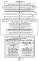
- FIG. 2Ais a first part of a flowchart of an exemplary method of generating an image in accordance with an exemplary embodiment.
- FIG. 2Bis a second part of a flowchart of an exemplary method of generating an image in accordance with an exemplary embodiment.
- FIG. 2comprises the combination of FIG. 2A and FIG. 2B .
- FIG. 3illustrates a camera device implemented in accordance with one embodiment of the present invention.
- FIG. 4is an assembly of modules, which may be included in a camera device, in accordance with an exemplary embodiment.
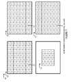
- FIG. 5is a drawing illustrating exemplary captured image areas of a scene corresponding to a plurality of camera modules in accordance with an exemplary embodiment.
- FIG. 6illustrates exemplary identified corresponding image portion corresponding to the example of FIG. 5 in accordance with an exemplary embodiment.
- FIG. 7illustrates exemplary determined sharpness level values corresponding to the example of FIG. 6 in accordance with an exemplary embodiment.
- FIG. 8illustrates an exemplary composite image of selected sharpest portions corresponding to the example of FIG. 7 in accordance with an exemplary embodiment.
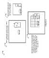
- FIG. 9illustrates an example of identifying sets of corresponding image portions corresponding to two captured images from camera modules with different focal lengths based on the comparison of detected objects in accordance with an exemplary embodiment.
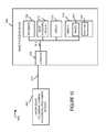
- FIG. 10illustrates a camera system including a camera device and an image processing device which can be used in accordance with the present invention.
- FIG. 1is an illustration 100 of an exemplary scene area showing objects at different distances from a camera device.
- Exemplary objectsinclude a very distant mountain range 102 , a first person 104 at the base on the mountain range, a first car 106 and a second person 108 in the far distance, a second car 110 , a third person 112 , and a fourth person 114 at medium distance, a fifth person 116 and a sixth person 118 at a near distance, and a head 120 of a seventh person at a very close distance with respect to the camera.
- a camera deviceimplementing a method in accordance with the present invention generates an overall sharp composite image by combining sharp image portions from images captured by a plurality of camera modules, e.g., optical chains, included in the camera device, at least some of said plurality of camera modules having different depths of field.
- a plurality of camera modulese.g., optical chains
- FIG. 2is a flowchart 200 of an exemplary method of generating an image in accordance with an exemplary embodiment that is implemented by a camera system.
- the camera systemmaybe a camera device such as the one shown in FIG. 3 or a combination of a camera device and an external processing device such as a computer system as shown in FIG. 10 .
- the processing devicewhich maybe, e.g., a personal computer or network based image processing device, can receive images from a camera device and processes the images to generate a composite image in accordance with the invention.
- the exemplary method of flowchart 200may be, and in various embodiments is, performed by a camera device including camera modules, and at least some of the camera modules have different focal length, have the same focal length but different apertures, or have the same focal length, same aperture and different sensor pixel sizes, where the sensor pixel size is the area used by a sensor to detect 1 pixel. These various combinations cause different camera modules to have different depths of field.
- the method 200maybe, and in some embodiments is, implemented by the exemplary camera device 300 shown in FIG. 3 and will be explained using as an example the case where the camera device 300 performs the steps shown in FIG. 2 .
- the inventionis not limited to an embodiment implemented fully in a camera device and that in some embodiments some or all of the image processing may be performed in an image processing device coupled to the camera device.
- the camera device 300is a handheld camera.
- Operationstarts in step 202 in which the camera device and, optionally the corresponding image processing device in the case of the FIG. 10 example, is powered on and initialized. Operation proceeds from step 202 to step 204 .
- the camera devicereceives user input identifying an object to focus on, e.g., user input indicates a touch of a touch screen displaying an image of a scene, the touch identifying an object in the scene. Operation proceeds from step 204 to step 206 .
- the camera devicefocuses camera modules, e.g., optical chains, based on the user identified object. While, the object the user selected for focusing the camera modules is the same, some camera modules may have more limited focus adjustment than other camera modules, and thus when the object is beyond the maximum focus distance of a module the module will be set to its maximum focus distance.
- a plurality of camera modules with different depths of fieldmay be, and sometimes are, set to focus at the same distance, e.g., in the case where the selected object to be focused on is within the focus range of multiple modules with different depth of fields. Operation proceeds from step 206 to step 208 .
- step 208the camera device captures multiple images of a scene using camera modules, e.g., optical chains. In various embodiments, the multiple images are captured in parallel. Operation proceeds from step 208 to step 209 in which a processor receives the multiple images captured in step 208 for processing.
- step 209maybe performed by the processor 308 .
- step 209maybe performed by the processor 1008 which will be used to process captured image and to generate a composite image therefrom. Generation of the depth map and/or other processing may be performed by either the processor of the camera device 308 or image processing device 1004 which is used in some but not all embodiments.
- step 210the camera device generates a depth map corresponding to said scene.
- generating a depth mapincludes processing images from different camera modules using triangulation techniques and/or processing stereo images to extract depth information.
- the depth mapmay assign objects of a captured scene to different depths with the number of possible depths depending on the particular implementation.
- the depth mapmay be represented as a grayscale image of the scene with each pixel value in the depth map corresponding to one of a possible number of different distances from the camera.
- the depth map informationcan, and in various embodiments is, used for subsequent image processing.
- the number of different depths in the depth mapmaybe limited to a predetermined number with each object, e.g., pixel or area corresponding to an object, in a scene being assigned to the depth to which it corresponds.
- step 212the camera device identifies portions of said multiple images which correspond to a same scene area, identified portions of the said multiple images corresponding to the same scene area being corresponding image portions.
- step 212includes steps 214 , 216 and 218 .
- step 214the camera device detects objects in each of said multiple images. Operation proceeds from step 214 to step 216 .
- step 216the camera device compares detected objects from different ones of said multiple images. Operation proceeds from step 216 to step 218 .
- step 218the camera device identifies image portions based on the comparison of the detected objects in said multiple images.
- Step 218includes step 220 in which the camera device identifies sets of corresponding image portions.
- step 222the camera device analyzes the image to determine an image portion sharpness level for each of a plurality of portions of said multiple images.
- step 222includes step 224 , which is performed for each individual image portion of the identified sets of corresponding image portions.
- step 224the camera device determines an image portion sharpness level for an image portion.
- step 224includes optional steps 226 and 228 .
- step 224includes optional steps 230 and 232 .
- step 226the camera device uses the generated depth map to determine a depth to which the image portion corresponds. Operation proceeds from step 226 to step 228 in which the camera device determines the image portion sharpness level based on the depth to which the image portion corresponds and the camera module used to capture the image portion. In some embodiments, at least some of the camera modules have different optical characteristics and different depths of field. In some embodiments, determining an image portion sharpness level for an image portion is based on an optical transfer function of the camera module which captured the image portion.
- the optical characteristics of the camera moduleis a function of at least one of: a depth of field setting, the focus distance, the focal length of the camera modules, and the distance from the camera to objects in said image portion as indicated based on the depth map.
- module 228determines a sharpness level for an image portion corresponding to a camera module based on depth information corresponding to the image portion, and knowledge of the lenses and their focus setting in the camera module.
- step 230the camera device performs a frequency analysis on the individual image portion. Operation proceeds from step 230 to step 232 , in which the camera device assigns a sharpness level to the individual image portion based on the frequency content of the image portion to which the sharpness level is being assigned.
- Operationproceeds from step 222 , via connecting node A 234 , to step 236 .
- step 236the camera device generates a composite image from said multiple images based on the determined image portion sharpness levels.
- Step 236includes step 238 and step 242 .
- step 238the camera device selects one image portion from each set of corresponding image portions to include in the composite image.
- Step 238includes step 240 .
- step 240for each identified set of corresponding image portions, the camera device selects, from the set of set of corresponding image portions generated by different camera modules, the image portion having the a highest sharpness level.
- at least some of the image portions in a set of corresponding image portionsare captured at different resolutions, and the selecting is performed without regard to the resolution of the image portion in said set of corresponding image portions.
- the image portions of the composite imageare non-overlapping. Operation proceeds from step 238 to step 242 , in which the camera device includes each selected image portion in the composite image.
- Operationproceeds from step 236 to step 244 , in which the camera device stores the generated composite image, e.g., in memory of the camera device. Operation proceeds from step 244 to step 246 in which the camera device displays the generated composite image, e.g., on a display screen of the camera device. Operation proceeds from step 246 to step 248 , in which the camera device transmits the generated composite image, e.g., via a wired and/or wireless interface, to one or more other devices.
- FIG. 3is a drawing of an exemplary camera device 300 in accordance with an exemplary embodiment.
- camera device 300is a portable handheld device.
- Exemplary camera device 300includes a plurality of camera modules, e.g., optical chain modules, at least some of the plurality of camera modules having different depth of field.
- Each camera module, e.g., optical chainincludes an aperture, one or more lenses, focusing control elements, e.g., for moving a lens or mirror, and a image sensor.
- the aperturesare fixed.
- the camera modulescapture images, e.g., multiple images in parallel corresponding to a scene, e.g., one image per camera module corresponding to the same scene.
- exemplary camera device 300includes one or more of: plurality of camera modules 302 , plurality of camera modules 302 ′ and plurality of camera module 302 ′′.
- Plurality of camera modules 302includes: one or more optical chains with focal length F 1 (optical chain 1 with focal length F 1 318 , . . . , optical chain n 1 with focal length F 1 320 ), a plurality of optical chains with focal length F 2 (optical chain 1 with focal length F 2 322 , . . .
- plurality of camera modules 302 ′includes: one or more optical chains with aperture 1 (optical chain 1 with aperture 1 318 ′, . . . , optical chain n 1 with aperture 1 320 ′), a plurality of optical chains with focal aperture 2 (optical chain 1 with aperture 2 322 ′, . . .
- plurality of camera modules 302 ′′includes: one or more optical chains with sensor pixel size 1 (optical chain 1 with sensor pixel size 1 318 ′′, . . . , optical chain n 1 with sensor pixel size 1 320 ′′), a plurality of optical chains with sensor pixel size 2 (optical chain 1 with sensor pixel size 2 322 ′′, . . .
- optical chain n 2 with sensor pixel size 2 324 ′′and a plurality of optical chains with sensor pixel size 3 (optical chain 1 with sensor pixel size 3 326 ′′, . . . , optical chain n 3 with sensor pixel size 3 328 ′′), where sensor pixel size 1 , sensor pixel size 2 , and sensor pixel size 3 are different.
- One exemplary sensor pixel sizeis 1.4 micron, e.g., which is a characteristic of one exemplary 8 megapixel sensor.
- Another exemplary sensor pixel sizeis 1.1 micron, which is a characteristic of one exemplary 14 megapixel sensor.
- Camera device 300further includes input devices 304 , output devices 306 , a processor 308 , e.g., a CPU, memory 310 , assembly of modules 312 , e.g., an assembly oh hardware modules such as an assembly of circuits, a wired interface 314 , and a wireless interface 315 .
- Input devices 304include switches 330 , buttons 332 , touch sensor 334 , and a microphone 336 .
- Received input via an input deviceincludes input indicating a user selection of an object on which to focus camera modules.
- Output devices 306include a display 338 , indicator lights 340 , and a speaker 342 .
- the display 338is a touch screen display which serves as both an output device for displaying an image and an input device for receiving input.
- Memory 310includes routines 344 and data/information 346 .
- Routines 344include an assembly of modules 348 , e.g., an assembly of software modules.
- Data/information 346includes, stored captured images from the camera modules, information identifying detected objects, information used to align multiple images, generated composite images, user selected information, camera module characteristic information, image portion frequency analysis information, depth map information, information identifying sets of corresponding image portions corresponding to multiple camera modules, determined image portion sharpness levels for individual image portions, determined maximum sharpness level for sets of corresponding image portions, information identifying the image portion corresponding to the determined maximum sharpness level for each of a plurality of sets of corresponding image portions.
- Wired interface 314includes a receiver 350 and a transmitter 352 , e.g., for communicating with other devices, e.g., via a network and/or the Internet. In some embodiments, generated composite images are communicated to other devices via wired interface 314 .
- Wireless interface 315includes a wireless receiver 351 coupled to receive antenna 355 and a wireless transmitter 352 coupled to transmit antenna 357 , e.g., for communicating with other devices including a wireless interface. In some embodiments, generated composite images are communicated to other devices via wireless interface 315 .
- Optical chains in plurality of camera modules( 302 , 302 ′, 302 ′′), input devices 304 , output devices 306 , processor 308 , memory 310 , assembly of modules 212 , wired interface 314 and wireless interface 314 are coupled together via a bus 316 over which the various elements may interchange data and information.
- FIG. 4is a drawing of an assembly of modules 400 , which may be included in a camera device implemented in accordance with the present invention, e.g., camera device 300 of FIG. 3 .
- Assembly of modules 400may implement steps of a method, e.g., steps of the method of flowchart 200 of FIG. 2 .
- assembly of modules 400is an assembly of circuits, which may be coupled together.
- assembly of modules 400is assembly of modules 312 of camera 300 of FIG. 3 .
- the assembly of module 400is an assembly of software modules.
- assembly of modules 400is assembly of modules 348 of memory 310 of camera 300 of FIG. 3 .
- the modules in the assembly of modules 400can, and in some embodiments are, implemented fully in hardware within the processor 308 , e.g., as individual circuits.
- the modules in the assembly of modules 400can, and in some embodiments are, implemented fully in hardware within the assembly of modules 312 , e.g., as individual circuits corresponding to the different modules.
- some of the modulesare implemented, e.g., as circuits, within the processor 308 with other modules being implemented, e.g., as circuits within assembly of modules 312 , external to and coupled to the processor.
- the level of integration of modules on the processor and/or with some modules being external to the processormay be one of design choice.
- modules in assembly of modules 400may be implemented in software and stored in the memory 310 of the camera device 300 , with the modules controlling operation of camera device 300 to implement the functions corresponding to the modules when the modules are executed by a processor, e.g., processor 308 .
- the assembly of modules 400is included in the memory 310 as assembly of modules 348 .
- various modules in assembly of modules 400are implemented as a combination of hardware and software, e.g., with another circuit external to the processor providing input to the processor 308 which then under software control operates to perform a portion of a module's function. While shown in the FIG. 3 embodiment as a single processor, e.g., computer, it should be appreciated that the processor 308 may be implemented as one or more processors, e.g., computers.
- the modulesWhen implemented in software the modules include code, which when executed by the processor 308 , configure the processor 308 to implement the function corresponding to the module.
- the memory 310is a computer program product comprising a computer readable medium comprising code, e.g., individual code for each module, for causing at least one computer, e.g., processor 308 , to implement the functions to which the modules correspond.
- Completely hardware based or completely software based modulesmay be used. However, it should be appreciated that any combination of software and hardware, e.g., circuit implemented modules may be used to implement the functions. As should be appreciated, the modules illustrated in FIG. 4 control and/or configure the camera device 300 elements therein such as the processor 308 , to perform functions of the corresponding steps illustrated in the method flowchart 200 of FIG. 2 . Thus the assembly of modules 400 includes various modules that perform functions of the corresponding steps of the method shown in FIG. 2 .
- Assembly of modules 400includes a user input reception module 404 , a focus control module 406 , an image capture control module 408 , and a depth map generation module 410 .
- Assembly of modules 400further includes a corresponding portion identification module 412 , a sharpest level determination module 422 , a composite image generation module 436 , a composite image storage module 444 , a composite image display module 446 and a composite image transmission module 448 .
- User input reception module 404is configured to receive user input identifying an object to focus on, e.g., receive user input indicating a touch on a touch screen display an image.
- Focus control module 406is configured to control camera modules of the camera device to focus based on a user-identified object, e.g.
- some camera modulesmay have more limited focus adjustment than other modules and then when the selected object is beyond the maximum focus distance of a module the module will be set to its maximum distance.
- a plurality of camera modules with different depths of fieldcan be, and sometimes are, set to focus to the same distance. For example, this scenario is the case where the object selected to be focused on is with the focus range of multiple camera modules, e.g., optical chains, with different depths of field.
- Image capture control module 408is configured to control a plurality of camera modules, e.g., optical chains, to capture multiple images of a scene, at least some of said camera modules having different depths of field. In some embodiments, at least some of the camera modules being controlled by image capture control module 408 have different focal lengths, have the same focal length but different apertures, or have the same focal length, same aperture and different pixel sensor sizes. In various embodiments, image capture control module is configured to control a plurality of camera modules to captures images of a scene in parallel. Depth map generation module 410 is configured to generate a depth map corresponding to a scene, e.g., using captured images from multiple camera modules, e.g., multiple optical chains. In some embodiments, depth map generation module 410 uses triangulation techniques. In some embodiments, depth map generation module 410 processes stereo images to obtain depth information.
- depth map generation module 410uses triangulation techniques. In some embodiments, depth map generation module 410 processes stereo images to obtain depth information.
- Corresponding image portion identification module 412is configured to identify portions of multiple images which correspond to a same scene area, identified portions of images corresponding to the same scene area being corresponding image portions.
- Corresponding portion identification module 412includes an objected detection module 414 , an object comparison module 416 and a corresponding image portion object based identification module 418 .
- Object detection module 414is configured to detect objects in multiple images.
- Object comparison module 416is configured to compare detected objects from multiple images, e.g., to find the same objects occurring in multiple images and to locate the same detected objects in multiple images, e.g., for the purposes of alignment and/or scaling.
- Corresponding image portion object based identification module 418is configured to identify portions of images which correspond to the same scene area based on a comparison of objects detected in multiple images.
- Module 418includes a corresponding image portion set identification module 420 configured to identify sets of corresponding image portions from the multiple captured images.
- Sharpest level determination module 422is configured to determine an image portion sharpness level for each of a plurality of portions of said multiple images. Sharpest level determination module 422 includes an image portion sharpness level determination module 424 . Image portion sharpness level determination module is configured to determine a image portion sharpness level for an individual image portion of a captured image.
- module 424includes an image portion depth determination module 426 configured to determine a depth to which an image portion corresponds using a generated depth map, and a depth and camera module characteristic based sharpness level determination module 428 configured to determine the image portion sharpness level based on the depth to which said image portion corresponds and the camera module used to capture the image portion.
- at least some of the camera moduleshave different optical characteristics and different depths of field.
- module 428is configured to determine an image portion sharpness level for an image portion based on an optical transfer function of the camera module which captured the image portion.
- the optical characteristics of a camera moduleis a function of at least one of a depth of field setting, the focus distance, the focal length of the camera module and the distance from the camera to objects in said image portion as indicated based on said depth map.
- module 424determines a sharpest level based on depth information corresponding to the image portion and camera module information, corresponding to the particular camera module which captured the image portion for which the sharpness level is being determined; exemplary camera module information includes lens information and focus setting information.
- module 424includes an image portion frequency analysis module 430 configured to perform a frequency analysis on an individual image portion and a sharpness level assignment module 432 configured to assign an image portion sharpness level to an individual image portion based on the frequency content of the individual image portion to which the sharpness level is being assigned.
- Composite image generation module 436is configured to generate a composite image from multiple images, e.g., based on determined image portion sharpness levels.
- Composite image generation module 436includes an image portion selection module 438 and a selected portion inclusion module 442 .
- Image portion selection module 438includes a sharpest image portion determination module 440 .
- Image portion selection module 438is configured to select from a set of corresponding image portions generated by different camera modules the image portion having the highest sharpness level.
- Sharpest image portion determination module 440is configured to determine which image portion is a set of corresponding image portions has the highest sharpness, e.g., based on a comparison of determined sharpness levels corresponding to each individual image portion in a set of corresponding image portions.
- Selected portion inclusion module 442is configured to include selected image portions in a composite image, one image portion from each of the sets of corresponding image portions, each selected image portion corresponding to an area of the composite image.
- the image portions of the composite imageare non-overlapping.
- At least some of the image portions in a set of corresponding image portionsare captured at different resolutions, and said selecting performed by image portion selection module 438 is performed without regard to the resolution of the image portion in said set of corresponding image portions.
- FIG. 5is a drawing 500 drawings 502 illustrating exemplary captured images by a plurality of camera modules included in an exemplary camera device and a table 504 identifying camera module characteristics.
- the camera modulese.g., optical chains
- Drawing 502includes a drawing 505 , a drawing 507 , a drawing 515 , and a drawing 547 .
- Drawing 505 , 507 , 515 and 547correspond to the same scene and may be viewed as aligned on top of one another.
- captured imagesare shown as being aligned.
- the alignment between captured imagesis not known or is not precise, e.g., there may be some variation that is not known in advance, and image object detection is used to align images captured by different camera module corresponding to the same scene.
- camera modules with different focal lengthshave different depths of field.
- Drawing 505illustrates camera module A image capture area 506 .
- Drawing 507illustrates camera module B image capture area 508 , camera module C image capture area 510 , camera module D image capture area 512 , and camera module E image capture area 514 .
- Drawing 515illustrates camera module F image capture area 516 , camera module G image capture area 518 , camera module H image capture area 520 , camera module I image capture area 522 , camera module J image capture area 524 , camera module K image capture area 526 , camera module L image capture area 528 , camera module M image capture area 530 camera module N image capture area 532 , camera module O image capture area 534 , camera module P image capture area 536 , camera module Q image capture area 538 camera module R image capture area 540 , camera module S image capture area 542 , camera module T image capture area 544 , and camera module U image capture area 546 .
- Drawing 547illustrates camera module V image capture area 548 .
- FIG. 6is a drawing 600 illustrating identified corresponding image portions for the captured images of FIG. 5 .
- Drawing 602illustrating exemplary image portions corresponding to the image captured by camera module A.
- Drawing 604illustrating exemplary image portions corresponding to the images captured by camera modules B, C, D, and E.
- Drawing 606illustrating exemplary image portions corresponding to the images captured by camera modules F, G, H, I, J, K, L, M, N, O, P, Q, R, S, T, and U.
- Drawing 608illustrating exemplary image portions corresponding to the image captured by camera module V.
- an individual image portionis identified by “PN 1 L 1 ”.
- a set of corresponding image portionshas the same number for “N 1 ”.
- L1identifies the module to which the individual image portion corresponds.
- one set of corresponding image portionsis: ⁇ image portion P 19 A 650 , image portion P 19 B 652 , image portion P 19 K 654 , P 19 V 656 ⁇ .
- each of the 64 sets of corresponding image portionsincludes 3 or 4 elements.
- FIG. 7is a drawing 700 illustrating determined sharpness level values for each of the individual image portions corresponding to FIG. 6 .
- an image sharpness levelis one value in the set of ⁇ 0, 1, 2, 3, 4, 5, 6, 7 ⁇ , where 7 represents the highest sharpness and 0 represents the lowest sharpness.
- Drawing 702illustrating exemplary determined sharpness levels for the individual image portions corresponding to the image captured by camera module A.
- Drawing 704illustrating exemplary determined image sharpness levels for the image portions corresponding to the images captured by camera modules B, C, D, and E.
- Drawing 706illustrating exemplary determined image sharpness levels for the individual image portions corresponding to the images captured by camera modules F, G, H, I, J, K, L, M, N, O, P, Q, R, S, T, and U.
- Drawing 708illustrating exemplary determined sharpness levels for the individual image portions corresponding to the image captured by camera module V.
- FIG. 8is a drawing 800 illustrating a composite image including selected sharpest portions of sets of corresponding image portions, one selected image portions per set of corresponding image portions.
- the selected portion in a set of corresponding image portionsis the portion with the determined highest sharpness level.
- the sharpest level for image portion P 51 D 808is the highest, image portion P 51 D 808 is included as part of generated composite image 800 of FIG. 8 .
- FIG. 9includes drawing 900 which illustrates an example of identifying sets of corresponding image portions corresponding to two captured images from camera modules with different focal lengths based on the comparison of detected objects in accordance with an exemplary embodiment.
- Drawing 900includes drawing 902 illustrating a image of scene area captured by an exemplary first camera module with a first focal length, a drawing 904 illustrating an image of the scene area captured by an exemplary second camera module with a second focal length which is different from the first focal length.
- the two images 902 , 904are, e.g., captured in parallel by different camera modules of the same camera device, the different camera modules having different depths of field.
- Drawing 906illustrates identified sets of corresponding image portions, e.g., set identified by a grid box, based on detected objects in the images, e.g., car, window, door, portion of house, etc., and known capture area size relationship information.
- objects detected in multiple imagesare used to align and/or scale the image and overlay the images and identify sets of corresponding image portions.
- FIG. 10illustrates a camera system 1000 including a camera device 1002 and an image processing device 104 which can be used in accordance with the present invention.
- the camera device 1002maybe the same or similar to the camera 300 shown in FIG. 3 .
- the camera device 1002is coupled to the image processing device 1004 via a communications link 1003 which maybe a wireless link, network link or wired link such as a USB cable.
- Image processing device 1004maybe a personal computer or network node, such as a cloud server, capable of receiving images from the camera device 1002 , processing said images, and sending one or more control signals to the camera device 1002 .
- the image processing device 1004includes an interface 1006 with which it can receive from, and send data and/or other information to the camera device 1002 .
- the image processing device 1004includes interface 1006 that is coupled via bus 1016 to a processor 1008 , image processing module 1010 , display 1012 and memory 1014 .
- the various elements coupled to the bus 1016can communicate over the bus with each other and via interface 1006 with external elements including the camera device 1002 and other network elements which can communicate with the image processing device via a network and interface 10006 .
- the processor 1008can and does receive and processes images form the camera device 1002 . Processing can include depth map generation, camera device control and/or generation of a composite image in accordance with the steps of the method shown in FIG. 2 .
- the memory 1014includes images, e.g., received images and generated composite images and one or more routines 1022 which control the image processing device to implement the steps of the methods of the invention including the image processing steps shown in FIG. 2 .
- imagese.g., received images and generated composite images
- routines 1022which control the image processing device to implement the steps of the methods of the invention including the image processing steps shown in FIG. 2 .
- Image processing module 1010maybe and sometimes is implemented as a dedicated image processing circuit responsible for generating the depth map and/or composite image in a hardware circuit.
- modulesare implemented fully in hardware, e.g., as a circuit or combination of circuit and optical elements.
- the camera system implementing the method of FIG. 2can be implemented in a single camera device, e.g., a portable handheld camera or can be implemented in a distributed manner with the camera device capturing images and various image processing operations being performed using hardware, e.g., a personal computer or network node, to perform one or more image processing operations outside the camera device.
- Various embodimentsmay be implemented using software, hardware and/or a combination of software and hardware.
- Various embodimentsare directed to apparatus, e.g., a camera device, an image processing device or a system.
- Various embodimentsare also directed to methods, e.g., a method of generating combined pixel values from sets of input pixel values corresponding to an image area where each set of pixel values may be provided by a different optical chain module.
- Various embodimentsare also directed to machine, e.g., computer, readable medium, e.g., ROM, RAM, CDs, hard discs, etc., which include machine readable instructions for controlling a machine, e.g., camera device, processor or image processing system, to implement one or more steps of one or more of the methods described in the present application.
- machinee.g., computer, readable medium, e.g., ROM, RAM, CDs, hard discs, etc.
- machinee.g., camera device, processor or image processing system
- apparatus described hereinare implemented using one or more modules to perform the steps corresponding to one or more methods.
- various featuresare implemented using modules.
- modulesmay be implemented using software, hardware or a combination of software and hardware.
- Optical chain modulesas should be appreciated include as least some hardware elements such as an image sensor and are therefore normally not implementable purely in software while other modules may be implemented fully in software.
- the modulesare implemented in hardware, the modules are implemented as circuits, e.g., of a processor and/or as a combination of hardware elements such as lenses, filters and an image sensor.
- methods and/or method stepscan, and in some embodiments are, implemented using computer executable instructions, such as software, included in a computer readable medium, e.g., a non-transitory computer readable medium, such as a memory device, e.g., RAM, floppy disk, etc. which when executed control a machine, e.g., general purpose computer or processor, with or without additional hardware, to implement all or portions of the above described methods.
- a computer readable mediume.g., a non-transitory computer readable medium, such as a memory device, e.g., RAM, floppy disk, etc.
- a machinee.g., general purpose computer or processor
- various embodimentsare directed to a computer readable medium including computer executable instructions for causing a machine, e.g., processor or computer system, to perform one or more of the steps of the above-described method(s).
- Some embodimentsare directed to a processor configured to implement one or more of the various functions, steps, acts and/or operations of one or more methods described above. Accordingly, some embodiments are directed to a processor, e.g., CPU, configured to implement some or all of the steps of the methods described herein.
- the processormay be for use in, e.g., a camera device, an image processing device or other type of system.
- the image processing deviceis a portable device including a camera, e.g., a cell phone including a camera with a processor that implements the method.
- modulesare implemented using software, in other embodiments modules are implemented in hardware, in still other embodiments the modules are implemented using a combination of hardware and/or software.
Landscapes
- Engineering & Computer Science (AREA)
- Physics & Mathematics (AREA)
- General Physics & Mathematics (AREA)
- Theoretical Computer Science (AREA)
- Multimedia (AREA)
- Signal Processing (AREA)
- Computer Vision & Pattern Recognition (AREA)
- Human Computer Interaction (AREA)
- Studio Devices (AREA)
Abstract
Description
Claims (20)
Priority Applications (1)
| Application Number | Priority Date | Filing Date | Title |
|---|---|---|---|
| US14/689,689US9824427B2 (en) | 2015-04-15 | 2015-04-17 | Methods and apparatus for generating a sharp image |
Applications Claiming Priority (2)
| Application Number | Priority Date | Filing Date | Title |
|---|---|---|---|
| US201562148155P | 2015-04-15 | 2015-04-15 | |
| US14/689,689US9824427B2 (en) | 2015-04-15 | 2015-04-17 | Methods and apparatus for generating a sharp image |
Publications (2)
| Publication Number | Publication Date |
|---|---|
| US20160309141A1 US20160309141A1 (en) | 2016-10-20 |
| US9824427B2true US9824427B2 (en) | 2017-11-21 |
Family
ID=57128612
Family Applications (1)
| Application Number | Title | Priority Date | Filing Date |
|---|---|---|---|
| US14/689,689Active2035-12-30US9824427B2 (en) | 2015-04-15 | 2015-04-17 | Methods and apparatus for generating a sharp image |
Country Status (1)
| Country | Link |
|---|---|
| US (1) | US9824427B2 (en) |
Cited By (17)
| Publication number | Priority date | Publication date | Assignee | Title |
|---|---|---|---|---|
| US9955082B2 (en) | 2013-10-18 | 2018-04-24 | Light Labs Inc. | Methods and apparatus for capturing images using optical chains and/or for using captured images |
| US9967535B2 (en) | 2015-04-17 | 2018-05-08 | Light Labs Inc. | Methods and apparatus for reducing noise in images |
| US9998638B2 (en) | 2014-12-17 | 2018-06-12 | Light Labs Inc. | Methods and apparatus for implementing and using camera devices |
| US10003738B2 (en) | 2015-12-18 | 2018-06-19 | Light Labs Inc. | Methods and apparatus for detecting and/or indicating a blocked sensor or camera module |
| US10009530B2 (en) | 2013-10-18 | 2018-06-26 | Light Labs Inc. | Methods and apparatus for synchronized image capture using camera modules with different focal lengths |
| US10051182B2 (en) | 2015-10-05 | 2018-08-14 | Light Labs Inc. | Methods and apparatus for compensating for motion and/or changing light conditions during image capture |
| US10091447B2 (en) | 2015-04-17 | 2018-10-02 | Light Labs Inc. | Methods and apparatus for synchronizing readout of multiple image sensors |
| US10129483B2 (en) | 2015-06-23 | 2018-11-13 | Light Labs Inc. | Methods and apparatus for implementing zoom using one or more moveable camera modules |
| US10205862B2 (en) | 2013-10-18 | 2019-02-12 | Light Labs Inc. | Methods and apparatus relating to a camera including multiple optical chains |
| US10225445B2 (en) | 2015-12-18 | 2019-03-05 | Light Labs Inc. | Methods and apparatus for providing a camera lens or viewing point indicator |
| US10365480B2 (en) | 2015-08-27 | 2019-07-30 | Light Labs Inc. | Methods and apparatus for implementing and/or using camera devices with one or more light redirection devices |
| US10491806B2 (en) | 2015-08-03 | 2019-11-26 | Light Labs Inc. | Camera device control related methods and apparatus |
| US10516834B2 (en) | 2015-10-06 | 2019-12-24 | Light Labs Inc. | Methods and apparatus for facilitating selective blurring of one or more image portions |
| US10670858B2 (en) | 2017-05-21 | 2020-06-02 | Light Labs Inc. | Methods and apparatus for maintaining and accurately determining the position of a moveable element |
| US10931866B2 (en) | 2014-01-05 | 2021-02-23 | Light Labs Inc. | Methods and apparatus for receiving and storing in a camera a user controllable setting that is used to control composite image generation performed after image capture |
| US11102395B2 (en) | 2019-08-16 | 2021-08-24 | Sony Corporation | Generation of media content having multi-focus video and multi-directional audio |
| WO2021223860A1 (en) | 2020-05-05 | 2021-11-11 | Fraunhofer-Gesellschaft zur Förderung der angewandten Forschung e.V. | Acquiring a digital image of an image content |
Families Citing this family (8)
| Publication number | Priority date | Publication date | Assignee | Title |
|---|---|---|---|---|
| US10237473B2 (en)* | 2015-09-04 | 2019-03-19 | Apple Inc. | Depth map calculation in a stereo camera system |
| WO2018109109A1 (en) | 2016-12-16 | 2018-06-21 | Sony Corporation | An optical scope system for capturing an image of a scene |
| CN109218572A (en)* | 2017-07-05 | 2019-01-15 | 北京臻迪科技股份有限公司 | A kind of image-pickup method, system and unmanned plane |
| US10931546B2 (en) | 2018-06-30 | 2021-02-23 | EMC IP Holding Company LLC | Data reduction techniques for a multi-sensor internet of things environment |
| US10796411B2 (en)* | 2018-07-20 | 2020-10-06 | EMC IP Holding Company LLC | Super-resolution imaging for a multi-sensor internet of things environment |
| US11405547B2 (en)* | 2019-02-01 | 2022-08-02 | Electronics And Telecommunications Research Institute | Method and apparatus for generating all-in-focus image using multi-focus image |
| CN112492212B (en)* | 2020-12-02 | 2022-05-06 | 维沃移动通信有限公司 | Photographing method, device, electronic device and storage medium |
| WO2022200844A1 (en)* | 2021-03-25 | 2022-09-29 | Telefonaktiebolaget Lm Ericsson (Publ) | Systems and methods for labeling and prioritization of sensory events in sensory environments |
Citations (164)
| Publication number | Priority date | Publication date | Assignee | Title |
|---|---|---|---|---|
| US4890133A (en) | 1987-03-26 | 1989-12-26 | Asahi Kogaku Kogyo K.K. | Autofocus camera |
| US5078479A (en) | 1990-04-20 | 1992-01-07 | Centre Suisse D'electronique Et De Microtechnique Sa | Light modulation device with matrix addressing |
| US5153569A (en) | 1990-04-24 | 1992-10-06 | Sony Corporation | Visual image display apparatus having a video display for one eye and a controllable shutter for the other eye |
| US5353068A (en) | 1992-08-31 | 1994-10-04 | Sony Corporation | Video signal combining apparatus and method |
| US5583602A (en) | 1994-04-07 | 1996-12-10 | Kyocera Corporation | Autofocus single-lens reflex camera |
| JPH1091765A (en) | 1996-09-10 | 1998-04-10 | Canon Inc | Image synthesis apparatus and method |
| US5781331A (en) | 1997-01-24 | 1998-07-14 | Roxburgh Ltd. | Optical microshutter array |
| US5889553A (en) | 1993-11-17 | 1999-03-30 | Canon Kabushiki Kaisha | Image pickup apparatus capable of high resolution imaging |
| US5975710A (en) | 1997-06-06 | 1999-11-02 | Luster; Spencer D. | Optical image field splitting system |
| US5982951A (en) | 1996-05-28 | 1999-11-09 | Canon Kabushiki Kaisha | Apparatus and method for combining a plurality of images |
| US6011661A (en) | 1998-04-07 | 2000-01-04 | Weng; Leo | Optical holder for an optical apparatus |
| US6028600A (en) | 1997-06-02 | 2000-02-22 | Sony Corporation | Rotary menu wheel interface |
| US6081670A (en) | 1999-03-05 | 2000-06-27 | Lifetouch National School Studies Inc. | Depth-of-field indicator for a camera |
| US6141034A (en) | 1995-12-15 | 2000-10-31 | Immersive Media Co. | Immersive imaging method and apparatus |
| JP2001061109A (en) | 1999-08-20 | 2001-03-06 | Japan Science & Technology Corp | Image input device |
| US20020149691A1 (en) | 1998-02-25 | 2002-10-17 | Francisco Pereira | Aperture coded camera for three dimensional imaging |
| US20030018427A1 (en) | 2001-07-21 | 2003-01-23 | Tatsuo Yokota | Display method and apparatus for navigation system |
| US20030020814A1 (en) | 2001-07-25 | 2003-01-30 | Fuji Photo Film Co., Ltd. | Image capturing apparatus |
| US20030185551A1 (en) | 2002-03-28 | 2003-10-02 | Chen Wen Ching | Simple focusable lens combination of a camera |
| US20040100479A1 (en) | 2002-05-13 | 2004-05-27 | Masao Nakano | Portable information terminal, display control device, display control method, and computer readable program therefor |
| JP2004289214A (en) | 2003-03-19 | 2004-10-14 | Minolta Co Ltd | Imaging apparatus |
| US20040227839A1 (en) | 2003-05-13 | 2004-11-18 | Stavely Donald J. | Systems and methods for determining focus from light collected by the periphery of a lens |
| US20050088546A1 (en) | 2003-10-27 | 2005-04-28 | Fuji Photo Film Co., Ltd. | Photographic apparatus |
| US20050200012A1 (en) | 2004-03-10 | 2005-09-15 | Kinsman Larry D. | Chip size image sensor camera module |
| US20060067672A1 (en) | 2004-09-21 | 2006-03-30 | Canon Kabushiki Kaisha | Photographing apparatus and control method therefor |
| JP2006106230A (en) | 2004-10-04 | 2006-04-20 | Nikon Corp | camera |
| US20060187338A1 (en) | 2005-02-18 | 2006-08-24 | May Michael J | Camera phone using multiple lenses and image sensors to provide an extended zoom range |
| US20060221218A1 (en) | 2005-04-05 | 2006-10-05 | Doron Adler | Image sensor with improved color filter |
| US20060238886A1 (en) | 2005-04-25 | 2006-10-26 | Taro Kushida | Zoom lens and image pickup apparatus |
| US20060281453A1 (en) | 2005-05-17 | 2006-12-14 | Gesturetek, Inc. | Orientation-sensitive signal output |
| US20070046776A1 (en)* | 2005-08-29 | 2007-03-01 | Hiroichi Yamaguchi | Stereoscopic display device and control method therefor |
| US20070050139A1 (en) | 2005-04-27 | 2007-03-01 | Sidman Adam D | Handheld platform stabilization system employing distributed rotation sensors |
| US20070065012A1 (en) | 2005-09-16 | 2007-03-22 | Seiko Epson Corporation | Image processing apparatus, image processing method, and program product |
| US20070127915A1 (en) | 2005-12-02 | 2007-06-07 | Premier Image Technology Corporation | Digital camera |
| JP2007164258A (en) | 2005-12-09 | 2007-06-28 | Kurabo Ind Ltd | Image composition processing apparatus and method |
| US20070177047A1 (en) | 2006-01-31 | 2007-08-02 | Hisashi Goto | Taking apparatus |
| US20070182528A1 (en) | 2000-05-08 | 2007-08-09 | Automotive Technologies International, Inc. | Vehicular Component Control Methods Based on Blind Spot Monitoring |
| JP2007201915A (en) | 2006-01-27 | 2007-08-09 | Yamaha Corp | Planar camera unit |
| US7280735B2 (en) | 2004-06-07 | 2007-10-09 | Andre Sean Thibault | Combined optical fiber wheel, beamsplitter, switch, and logic gate |
| US7315423B2 (en) | 2005-03-25 | 2008-01-01 | Fujinon Corporation | Zoom lens including four lens groups |
| US20080030592A1 (en) | 2006-08-01 | 2008-02-07 | Eastman Kodak Company | Producing digital image with different resolution portions |
| KR20080022260A (en) | 2006-09-06 | 2008-03-11 | 엘지전자 주식회사 | Zoom lens optics |
| US20080074755A1 (en) | 2006-09-07 | 2008-03-27 | Smith George E | Lens array imaging with cross-talk inhibiting optical stop structure |
| US20080084484A1 (en) | 2006-10-10 | 2008-04-10 | Nikon Corporation | Camera |
| US20080111881A1 (en) | 2006-11-09 | 2008-05-15 | Innovative Signal Analysis, Inc. | Imaging system |
| US20080180562A1 (en) | 2007-01-31 | 2008-07-31 | Canon Kabushiki Kaisha | Image pickup apparatus |
| US20080211941A1 (en) | 2007-03-01 | 2008-09-04 | Deever Aaron T | Digital camera using multiple image sensors to provide improved temporal sampling |
| US20080219654A1 (en) | 2007-03-09 | 2008-09-11 | Border John N | Camera using multiple lenses and image sensors to provide improved focusing capability |
| US20080240698A1 (en) | 2007-03-28 | 2008-10-02 | Sony Ericsson Mobile Communications Ab | Zoom control |
| US20080247745A1 (en) | 2007-04-04 | 2008-10-09 | Nilsson Rene | Camera assembly with zoom imaging and method |
| US20080251697A1 (en) | 2005-01-25 | 2008-10-16 | Samsung Electronics Co., Ltd. | Image sensor and method of fabrication |
| JP2008268937A (en) | 2007-03-29 | 2008-11-06 | Kyocera Corp | Imaging apparatus and imaging method |
| US20080278610A1 (en) | 2007-05-11 | 2008-11-13 | Micron Technology, Inc. | Configurable pixel array system and method |
| US20090086032A1 (en) | 2007-09-28 | 2009-04-02 | Altek Corporation | System for detecting and compensating camera movement and a method thereof |
| US20090136223A1 (en) | 2005-11-22 | 2009-05-28 | Matsushita Electric Industrial Co., Ltd. | Image taking device, portabe terminal device, image taking method, and program |
| US20090154821A1 (en) | 2007-12-13 | 2009-06-18 | Samsung Electronics Co., Ltd. | Method and an apparatus for creating a combined image |
| US7551358B2 (en) | 2006-07-05 | 2009-06-23 | Samsung Electro-Mechanics Co., Ltd. | Camera module having an array lens |
| US20090167923A1 (en)* | 2007-12-27 | 2009-07-02 | Ati Technologies Ulc | Method and apparatus with depth map generation |
| US7561201B2 (en) | 2004-10-01 | 2009-07-14 | Samsung Techwin Co., Ltd. | Method for operating a digital photographing apparatus using a touch screen and a digital photographing apparatus using the method |
| US20090225203A1 (en) | 2008-02-28 | 2009-09-10 | Funai Electric Co., Ltd. | Compound-eye imaging device |
| US20090278950A1 (en) | 2008-05-09 | 2009-11-12 | Micron Technology, Inc. | Lens cleaning warning system and method |
| US20090290042A1 (en) | 2008-05-23 | 2009-11-26 | Seiko Epson Corporation | Development processing device, development processing method, and storage medium of computer program for development process |
| US20100013906A1 (en) | 2008-07-17 | 2010-01-21 | Border John N | Zoom by multiple image capture |
| US20100034531A1 (en) | 2008-08-06 | 2010-02-11 | Samsung Electro-Mechanics Co., Ltd. | Camera module and method of manufacturing the same |
| US20100045774A1 (en) | 2008-08-22 | 2010-02-25 | Promos Technologies Inc. | Solid-state panoramic image capture apparatus |
| JP2010049263A (en) | 2009-09-14 | 2010-03-04 | Olympus Corp | Electronic imaging apparatus |
| US20100053414A1 (en) | 2008-01-11 | 2010-03-04 | Satoshi Tamaki | Compound eye camera module |
| US20100079635A1 (en) | 2008-09-26 | 2010-04-01 | Sharp Kabushiki Kaisha | Optical element wafer module, optical element module, method for manufacturing optical element module, electronic element wafer module, method for manufacturing electronic element module, electronic element module and electronic information device |
| US20100091089A1 (en) | 2008-10-15 | 2010-04-15 | Brian Cromwell | Infrared camera filter wheel systems and methods |
| US20100097443A1 (en) | 2008-10-16 | 2010-04-22 | Peter Lablans | Controller in a Camera for Creating a Panoramic Image |
| US20100214437A1 (en)* | 2009-02-25 | 2010-08-26 | Samsung Digital Imaging Co., Ltd. | Digital image processing apparatus, method of controlling the apparatus, and recording medium having recorded thereon a program for executing the method |
| US20100225755A1 (en) | 2006-01-20 | 2010-09-09 | Matsushita Electric Industrial Co., Ltd. | Compound eye camera module and method of producing the same |
| US7801428B2 (en) | 2006-03-14 | 2010-09-21 | Seiko Epson Corporation | Shot image display system, image receiving device, control method for image receiving device, and server |
| US20100238327A1 (en) | 2009-03-19 | 2010-09-23 | Griffith John D | Dual Sensor Camera |
| US7810511B2 (en) | 2006-05-15 | 2010-10-12 | Sony Ericsson Mobile Communications Ab | Lens cleaner |
| US20100265346A1 (en) | 2007-12-13 | 2010-10-21 | Keigo Iizuka | Camera system and method for amalgamating images to create an omni-focused image |
| JP2010256397A (en) | 2009-04-21 | 2010-11-11 | Kyocera Mita Corp | Optical scanning apparatus and image forming apparatus with the same |
| US20100283842A1 (en) | 2007-04-19 | 2010-11-11 | Dvp Technologies Ltd. | Imaging system and method for use in monitoring a field of regard |
| US20100296802A1 (en) | 2009-05-21 | 2010-11-25 | John Andrew Davies | Self-zooming camera |
| US20110025830A1 (en)* | 2009-07-31 | 2011-02-03 | 3Dmedia Corporation | Methods, systems, and computer-readable storage media for generating stereoscopic content via depth map creation |
| US20110051243A1 (en) | 2009-08-28 | 2011-03-03 | Su Yu-Hsiu | Prism type lens structure |
| KR20110022279A (en) | 2009-08-27 | 2011-03-07 | 삼성전기주식회사 | Camera module |
| US20110063325A1 (en) | 2009-09-16 | 2011-03-17 | Research In Motion Limited | Methods and devices for displaying an overlay on a device display screen |
| US20110069189A1 (en) | 2008-05-20 | 2011-03-24 | Pelican Imaging Corporation | Capturing and processing of images using monolithic camera array with heterogeneous imagers |
| US20110080655A1 (en) | 2009-10-06 | 2011-04-07 | Masao Mori | Imaging lens and imaging apparatus |
| US20110123115A1 (en) | 2009-11-25 | 2011-05-26 | Google Inc. | On-Screen Guideline-Based Selective Text Recognition |
| US20110128393A1 (en) | 2009-12-01 | 2011-06-02 | Nokia Corporation | Digital imaging |
| US20110157451A1 (en) | 2009-12-31 | 2011-06-30 | Hon Hai Precision Industry Co., Ltd. | Imaging device |
| US20110157430A1 (en) | 2009-12-28 | 2011-06-30 | Takeshi Hosoya | Image pickup apparatus having optical path reflecting zoom lens |
| US20110187878A1 (en) | 2010-02-02 | 2011-08-04 | Primesense Ltd. | Synchronization of projected illumination with rolling shutter of image sensor |
| US20110193984A1 (en) | 2010-02-05 | 2011-08-11 | Canon Kabushiki Kaisha | Imaging apparatus |
| US20110221920A1 (en) | 2010-03-11 | 2011-09-15 | Samsung Electronics Co., Ltd. | Digital photographing apparatus, method of controlling the same, and computer readable storage medium |
| US20110222167A1 (en) | 2010-03-12 | 2011-09-15 | Samsung Electronics Co., Ltd. | Compact zoom lens |
| US20110242342A1 (en) | 2010-04-05 | 2011-10-06 | Qualcomm Incorporated | Combining data from multiple image sensors |
| US20110280565A1 (en) | 2010-05-14 | 2011-11-17 | Chapman Leonard T | Dual loop camera stabilization systems and methods |
| US20110285895A1 (en) | 2010-05-21 | 2011-11-24 | Chung Shan Institute Of Science And Technology | Image Sensing Device and Processing System |
| US20120002096A1 (en) | 2010-07-05 | 2012-01-05 | Samsung Electronics Co., Ltd. | Imaging device including a plurality of imaging units |
| US20120019711A1 (en)* | 2004-10-01 | 2012-01-26 | The Board Of Trustees Of The Leland Stanford Junior Univeristy | Imaging arrangements and methods therefor |
| US20120033069A1 (en) | 2010-08-03 | 2012-02-09 | Faro Technologies Incorporated | Scanner display |
| US20120062691A1 (en) | 2010-04-06 | 2012-03-15 | Gordon Fowler | Camera Control |
| US8144230B2 (en) | 2008-06-02 | 2012-03-27 | Casio Computer Co., Ltd. | Camera, storage medium having stored therein camera control program, and camera control method |
| US8199222B2 (en) | 2007-03-05 | 2012-06-12 | DigitalOptics Corporation Europe Limited | Low-light video frame enhancement |
| US20120155848A1 (en) | 2010-12-16 | 2012-06-21 | Motorola-Mobility, Inc. | Method and System for Providing Viewfinder Operation in Mobile Device |
| US20120162464A1 (en) | 2010-12-27 | 2012-06-28 | Samsung Electronics Co., Ltd. | Digital image photographing apparatus and method of controlling the same |
| US20120188391A1 (en) | 2011-01-25 | 2012-07-26 | Scott Smith | Array camera having lenses with independent fields of view |
| US20120207462A1 (en) | 2011-02-11 | 2012-08-16 | Jeff Justice | Camera Mounting Assembly |
| US20120242881A1 (en) | 2011-03-23 | 2012-09-27 | Canon Kabushiki Kaisha | Lens apparatus and image pickup apparatus including the same |
| US20120249815A1 (en) | 2011-03-29 | 2012-10-04 | Mircrosoft Corporation | Folded imaging path camera |
| US20120257013A1 (en) | 2011-04-08 | 2012-10-11 | Sony Corporation | Analysis of 3d video |
| US20120257077A1 (en) | 2011-04-07 | 2012-10-11 | Olympus Corporation | Image pickup apparatus, image pickup method and recording device recording image processing program |
| US20120268642A1 (en) | 2011-04-21 | 2012-10-25 | Olympus Imaging Corporation | Driving apparatus and imaging apparatus using the same |
| US8320051B2 (en) | 2009-10-13 | 2012-11-27 | Panasonic Corporation | Zoom lens system, imaging device and camera |
| US20130027353A1 (en) | 2011-07-28 | 2013-01-31 | Jinwook Hyun | Touch-type portable terminal |
| US20130041221A1 (en)* | 2011-08-12 | 2013-02-14 | Intuitive Surgical Operations, Inc. | Image capture unit and an imaging pipeline with enhanced color performance in a surgical instrument and method |
| US20130050564A1 (en) | 2010-09-16 | 2013-02-28 | James E. Adams, Jr. | Producing focused videos from single captured video |
| US20130057743A1 (en) | 2011-09-02 | 2013-03-07 | Sony Corporation | Solid-state imaging device and camera system |
| US20130064531A1 (en) | 2011-09-13 | 2013-03-14 | Bruce Harold Pillman | Zoom flash with no moving parts |
| US20130076928A1 (en) | 2004-08-25 | 2013-03-28 | Protarius Filo Ag, L.L.C. | Large dynamic range cameras |
| US8417058B2 (en) | 2010-09-15 | 2013-04-09 | Microsoft Corporation | Array of scanning sensors |
| US20130088614A1 (en) | 2011-10-07 | 2013-04-11 | Jinsool LEE | Mobile terminal and method for generating an out-of-focus image |
| US20130086765A1 (en) | 2011-10-05 | 2013-04-11 | Hwan Ming Enterprise Co., Ltd | Automatic clean device for a surveillance camera |
| US20130093947A1 (en) | 2011-10-17 | 2013-04-18 | Samsung Electro-Mechanics Co., Ltd. | Camera module |
| US20130093842A1 (en) | 2011-10-12 | 2013-04-18 | Canon Kabushiki Kaisha | Image-capturing device |
| US20130100272A1 (en) | 2011-10-25 | 2013-04-25 | Sanford-Burnham Medical Research Institute | Multifunction autofocus system and method for automated microscopy |
| US20130155194A1 (en) | 2011-12-15 | 2013-06-20 | Thomson Licensing | Anagylphic stereoscopic image capture device |
| US20130153772A1 (en) | 2011-12-20 | 2013-06-20 | Heptagon Micro Optics Pte. Ltd. | Opto-electronic module and devices comprising the same |
| US20130194475A1 (en) | 2012-01-30 | 2013-08-01 | Pentax Ricoh Imaging Company, Ltd. | Digital camera |
| US8520022B1 (en) | 2012-10-24 | 2013-08-27 | Google Inc. | Method and system for improving screen readability in daylight with runtime color adjustment |
| US20130223759A1 (en) | 2012-02-28 | 2013-08-29 | Canon Kabushiki Kaisha | Image processing method and device, and program |
| US20130222676A1 (en) | 2010-10-01 | 2013-08-29 | Fujifilm Corporation | Imaging apparatus |
| EP2642757A2 (en) | 2012-03-19 | 2013-09-25 | Aptina Imaging Corporation | Imaging systems with clear filter pixels |
| US20130250125A1 (en) | 2009-03-02 | 2013-09-26 | Flir Systems, Inc. | Thermal image frame capture using de-aligned sensor array |
| US20130258044A1 (en) | 2012-03-30 | 2013-10-03 | Zetta Research And Development Llc - Forc Series | Multi-lens camera |
| US8553106B2 (en) | 2009-05-04 | 2013-10-08 | Digitaloptics Corporation | Dual lens digital zoom |
| US20130329013A1 (en)* | 2012-05-11 | 2013-12-12 | Proiam, Llc | Hand held dimension capture apparatus, system and method |
| US8619082B1 (en) | 2012-08-21 | 2013-12-31 | Pelican Imaging Corporation | Systems and methods for parallax detection and correction in images captured using array cameras that contain occlusions using subsets of images to perform depth estimation |
| US8639296B2 (en) | 2011-06-07 | 2014-01-28 | Lg Electronics Inc. | Mobile device and an image display method thereof |
| US20140049677A1 (en) | 2012-02-07 | 2014-02-20 | Olympus Imaging Corp. | Photographing apparatus and operation control method for the same |
| US8665341B2 (en) | 2010-08-27 | 2014-03-04 | Adobe Systems Incorporated | Methods and apparatus for rendering output images with simulated artistic effects from focused plenoptic camera data |
| US20140063018A1 (en) | 2012-08-29 | 2014-03-06 | JVC Kenwood Corporation | Depth estimation device, depth estimation method, depth estimation program, image processing device, image processing method, and image processing program |
| US8704944B1 (en) | 2011-02-25 | 2014-04-22 | Girling Kelly Design Group, LLC | Handheld modular digital photography system |
| US20140111650A1 (en) | 2012-10-19 | 2014-04-24 | Qualcomm Incorporated | Multi-camera system using folded optics |
| US20140152802A1 (en) | 2012-06-08 | 2014-06-05 | SeeScan, Inc. | Multi-camera pipe inspection apparatus, systems and methods |
| US8762895B2 (en) | 2012-10-28 | 2014-06-24 | Google Inc. | Camera zoom indicator in mobile devices |
| US20140192214A1 (en) | 2013-01-05 | 2014-07-10 | Tinz Optics, Inc. | Methods and apparatus for using multiple optical chains in paralell |
| US20140204244A1 (en) | 2013-01-18 | 2014-07-24 | Samsung Electronics Co., Ltd. | Method and apparatus for photographing in portable terminal |
| US20140226041A1 (en) | 2013-02-14 | 2014-08-14 | Canon Kabushiki Kaisha | Image processing apparatus, image pickup apparatus, image processing method, and non-transitory computer-readable storage medium |
| US20140267243A1 (en) | 2013-03-13 | 2014-09-18 | Pelican Imaging Corporation | Systems and Methods for Synthesizing Images from Image Data Captured by an Array Camera Using Restricted Depth of Field Depth Maps in which Depth Estimation Precision Varies |
| US20140293079A1 (en) | 2013-04-02 | 2014-10-02 | Google Inc | Camera Obstruction Detection |
| US8896655B2 (en) | 2010-08-31 | 2014-11-25 | Cisco Technology, Inc. | System and method for providing depth adaptive video conferencing |
| US20140354714A1 (en) | 2013-05-28 | 2014-12-04 | Infineon Technologies Ag | Display Device |
| US20150035824A1 (en) | 2013-08-02 | 2015-02-05 | Canon Kabushiki Kaisha | Imaging apparatus and method of controlling same |
| US20150043808A1 (en) | 2013-08-07 | 2015-02-12 | Canon Kabushiki Kaisha | Image processing apparatus, image processing method, and imaging apparatus |
| US20150049233A1 (en) | 2013-08-14 | 2015-02-19 | Samsung Electronics Co., Ltd. | Photographing apparatus and method of controlling the same |
| US9041826B2 (en) | 2005-06-02 | 2015-05-26 | The Invention Science Fund I, Llc | Capturing selected image objects |
| US20150154449A1 (en) | 2013-11-29 | 2015-06-04 | Fujitsu Limited | Method and apparatus for recognizing actions |
| US20150156399A1 (en) | 2013-11-29 | 2015-06-04 | Lite-On Electronics (Guangzhou) Limited | Automatic focusing method, and automatic focusing device, image capturing device using the same |
| US9104705B2 (en) | 2007-12-28 | 2015-08-11 | Canon Kabushiki Kaisha | Image display method, image display apparatus, image recording apparatus, and image pickup apparatus |
| US20150234149A1 (en) | 2014-02-19 | 2015-08-20 | Melvyn H. Kreitzer | Zoom lens optical system |
| US20150253647A1 (en) | 2014-03-07 | 2015-09-10 | Apple Inc. | Folded camera lens systems |
| US9135732B2 (en) | 2006-02-28 | 2015-09-15 | Microsoft Corporation | Object-level image editing |
| US20150279012A1 (en) | 2014-03-31 | 2015-10-01 | International Business Machines Corporation | Automatic focus stacking of captured images |
| US20160142610A1 (en) | 2014-11-17 | 2016-05-19 | Duelight Llc | System and method for generating a digital image |
| US9374514B2 (en) | 2013-10-18 | 2016-06-21 | The Lightco Inc. | Methods and apparatus relating to a camera including multiple optical chains |
- 2015
- 2015-04-17USUS14/689,689patent/US9824427B2/enactiveActive
Patent Citations (175)
| Publication number | Priority date | Publication date | Assignee | Title |
|---|---|---|---|---|
| US4890133A (en) | 1987-03-26 | 1989-12-26 | Asahi Kogaku Kogyo K.K. | Autofocus camera |
| US5078479A (en) | 1990-04-20 | 1992-01-07 | Centre Suisse D'electronique Et De Microtechnique Sa | Light modulation device with matrix addressing |
| US5153569A (en) | 1990-04-24 | 1992-10-06 | Sony Corporation | Visual image display apparatus having a video display for one eye and a controllable shutter for the other eye |
| US5353068A (en) | 1992-08-31 | 1994-10-04 | Sony Corporation | Video signal combining apparatus and method |
| US5889553A (en) | 1993-11-17 | 1999-03-30 | Canon Kabushiki Kaisha | Image pickup apparatus capable of high resolution imaging |
| US5583602A (en) | 1994-04-07 | 1996-12-10 | Kyocera Corporation | Autofocus single-lens reflex camera |
| US6141034A (en) | 1995-12-15 | 2000-10-31 | Immersive Media Co. | Immersive imaging method and apparatus |
| US5982951A (en) | 1996-05-28 | 1999-11-09 | Canon Kabushiki Kaisha | Apparatus and method for combining a plurality of images |
| JPH1091765A (en) | 1996-09-10 | 1998-04-10 | Canon Inc | Image synthesis apparatus and method |
| US5781331A (en) | 1997-01-24 | 1998-07-14 | Roxburgh Ltd. | Optical microshutter array |
| US6028600A (en) | 1997-06-02 | 2000-02-22 | Sony Corporation | Rotary menu wheel interface |
| US5975710A (en) | 1997-06-06 | 1999-11-02 | Luster; Spencer D. | Optical image field splitting system |
| US20020149691A1 (en) | 1998-02-25 | 2002-10-17 | Francisco Pereira | Aperture coded camera for three dimensional imaging |
| US6011661A (en) | 1998-04-07 | 2000-01-04 | Weng; Leo | Optical holder for an optical apparatus |
| US6081670A (en) | 1999-03-05 | 2000-06-27 | Lifetouch National School Studies Inc. | Depth-of-field indicator for a camera |
| JP2001061109A (en) | 1999-08-20 | 2001-03-06 | Japan Science & Technology Corp | Image input device |
| US7009652B1 (en) | 1999-08-20 | 2006-03-07 | Minolta Co. Ltd | Image input apparatus |
| US20070182528A1 (en) | 2000-05-08 | 2007-08-09 | Automotive Technologies International, Inc. | Vehicular Component Control Methods Based on Blind Spot Monitoring |
| US20030018427A1 (en) | 2001-07-21 | 2003-01-23 | Tatsuo Yokota | Display method and apparatus for navigation system |
| US20030020814A1 (en) | 2001-07-25 | 2003-01-30 | Fuji Photo Film Co., Ltd. | Image capturing apparatus |
| US20030185551A1 (en) | 2002-03-28 | 2003-10-02 | Chen Wen Ching | Simple focusable lens combination of a camera |
| US20040100479A1 (en) | 2002-05-13 | 2004-05-27 | Masao Nakano | Portable information terminal, display control device, display control method, and computer readable program therefor |
| JP2004289214A (en) | 2003-03-19 | 2004-10-14 | Minolta Co Ltd | Imaging apparatus |
| US20040227839A1 (en) | 2003-05-13 | 2004-11-18 | Stavely Donald J. | Systems and methods for determining focus from light collected by the periphery of a lens |
| US20050088546A1 (en) | 2003-10-27 | 2005-04-28 | Fuji Photo Film Co., Ltd. | Photographic apparatus |
| US20050200012A1 (en) | 2004-03-10 | 2005-09-15 | Kinsman Larry D. | Chip size image sensor camera module |
| US7280735B2 (en) | 2004-06-07 | 2007-10-09 | Andre Sean Thibault | Combined optical fiber wheel, beamsplitter, switch, and logic gate |
| US20130076928A1 (en) | 2004-08-25 | 2013-03-28 | Protarius Filo Ag, L.L.C. | Large dynamic range cameras |
| US20060067672A1 (en) | 2004-09-21 | 2006-03-30 | Canon Kabushiki Kaisha | Photographing apparatus and control method therefor |
| US20120019711A1 (en)* | 2004-10-01 | 2012-01-26 | The Board Of Trustees Of The Leland Stanford Junior Univeristy | Imaging arrangements and methods therefor |
| US7561201B2 (en) | 2004-10-01 | 2009-07-14 | Samsung Techwin Co., Ltd. | Method for operating a digital photographing apparatus using a touch screen and a digital photographing apparatus using the method |
| JP2006106230A (en) | 2004-10-04 | 2006-04-20 | Nikon Corp | camera |
| US20080251697A1 (en) | 2005-01-25 | 2008-10-16 | Samsung Electronics Co., Ltd. | Image sensor and method of fabrication |
| US20060187338A1 (en) | 2005-02-18 | 2006-08-24 | May Michael J | Camera phone using multiple lenses and image sensors to provide an extended zoom range |
| US7315423B2 (en) | 2005-03-25 | 2008-01-01 | Fujinon Corporation | Zoom lens including four lens groups |
| US20060221218A1 (en) | 2005-04-05 | 2006-10-05 | Doron Adler | Image sensor with improved color filter |
| US20060238886A1 (en) | 2005-04-25 | 2006-10-26 | Taro Kushida | Zoom lens and image pickup apparatus |
| US20070050139A1 (en) | 2005-04-27 | 2007-03-01 | Sidman Adam D | Handheld platform stabilization system employing distributed rotation sensors |
| US20060281453A1 (en) | 2005-05-17 | 2006-12-14 | Gesturetek, Inc. | Orientation-sensitive signal output |
| US9041826B2 (en) | 2005-06-02 | 2015-05-26 | The Invention Science Fund I, Llc | Capturing selected image objects |
| US20070046776A1 (en)* | 2005-08-29 | 2007-03-01 | Hiroichi Yamaguchi | Stereoscopic display device and control method therefor |
| US20070065012A1 (en) | 2005-09-16 | 2007-03-22 | Seiko Epson Corporation | Image processing apparatus, image processing method, and program product |
| US20090136223A1 (en) | 2005-11-22 | 2009-05-28 | Matsushita Electric Industrial Co., Ltd. | Image taking device, portabe terminal device, image taking method, and program |
| US20070127915A1 (en) | 2005-12-02 | 2007-06-07 | Premier Image Technology Corporation | Digital camera |
| JP2007164258A (en) | 2005-12-09 | 2007-06-28 | Kurabo Ind Ltd | Image composition processing apparatus and method |
| US8194169B2 (en) | 2006-01-20 | 2012-06-05 | Panasonic Corporation | Compound eye camera module and method of producing the same |
| US20100225755A1 (en) | 2006-01-20 | 2010-09-09 | Matsushita Electric Industrial Co., Ltd. | Compound eye camera module and method of producing the same |
| JP2007201915A (en) | 2006-01-27 | 2007-08-09 | Yamaha Corp | Planar camera unit |
| US20070177047A1 (en) | 2006-01-31 | 2007-08-02 | Hisashi Goto | Taking apparatus |
| US9135732B2 (en) | 2006-02-28 | 2015-09-15 | Microsoft Corporation | Object-level image editing |
| US7801428B2 (en) | 2006-03-14 | 2010-09-21 | Seiko Epson Corporation | Shot image display system, image receiving device, control method for image receiving device, and server |
| US7810511B2 (en) | 2006-05-15 | 2010-10-12 | Sony Ericsson Mobile Communications Ab | Lens cleaner |
| US7551358B2 (en) | 2006-07-05 | 2009-06-23 | Samsung Electro-Mechanics Co., Ltd. | Camera module having an array lens |
| US20080030592A1 (en) | 2006-08-01 | 2008-02-07 | Eastman Kodak Company | Producing digital image with different resolution portions |
| KR20080022260A (en) | 2006-09-06 | 2008-03-11 | 엘지전자 주식회사 | Zoom lens optics |
| US20080074755A1 (en) | 2006-09-07 | 2008-03-27 | Smith George E | Lens array imaging with cross-talk inhibiting optical stop structure |
| US20080084484A1 (en) | 2006-10-10 | 2008-04-10 | Nikon Corporation | Camera |
| US20080111881A1 (en) | 2006-11-09 | 2008-05-15 | Innovative Signal Analysis, Inc. | Imaging system |
| US20080180562A1 (en) | 2007-01-31 | 2008-07-31 | Canon Kabushiki Kaisha | Image pickup apparatus |
| US20080211941A1 (en) | 2007-03-01 | 2008-09-04 | Deever Aaron T | Digital camera using multiple image sensors to provide improved temporal sampling |
| US8199222B2 (en) | 2007-03-05 | 2012-06-12 | DigitalOptics Corporation Europe Limited | Low-light video frame enhancement |
| US20080219654A1 (en) | 2007-03-09 | 2008-09-11 | Border John N | Camera using multiple lenses and image sensors to provide improved focusing capability |
| US20080240698A1 (en) | 2007-03-28 | 2008-10-02 | Sony Ericsson Mobile Communications Ab | Zoom control |
| JP2008268937A (en) | 2007-03-29 | 2008-11-06 | Kyocera Corp | Imaging apparatus and imaging method |
| US8482637B2 (en) | 2007-03-29 | 2013-07-09 | Kyocera Corporation | Imaging device and imaging method having zoom optical system including a light wavefront modulation element |
| US20080247745A1 (en) | 2007-04-04 | 2008-10-09 | Nilsson Rene | Camera assembly with zoom imaging and method |
| US20100283842A1 (en) | 2007-04-19 | 2010-11-11 | Dvp Technologies Ltd. | Imaging system and method for use in monitoring a field of regard |
| US20080278610A1 (en) | 2007-05-11 | 2008-11-13 | Micron Technology, Inc. | Configurable pixel array system and method |
| US20090086032A1 (en) | 2007-09-28 | 2009-04-02 | Altek Corporation | System for detecting and compensating camera movement and a method thereof |
| US20100265346A1 (en) | 2007-12-13 | 2010-10-21 | Keigo Iizuka | Camera system and method for amalgamating images to create an omni-focused image |
| US20090154821A1 (en) | 2007-12-13 | 2009-06-18 | Samsung Electronics Co., Ltd. | Method and an apparatus for creating a combined image |
| US20090167923A1 (en)* | 2007-12-27 | 2009-07-02 | Ati Technologies Ulc | Method and apparatus with depth map generation |
| US9104705B2 (en) | 2007-12-28 | 2015-08-11 | Canon Kabushiki Kaisha | Image display method, image display apparatus, image recording apparatus, and image pickup apparatus |
| US20100053414A1 (en) | 2008-01-11 | 2010-03-04 | Satoshi Tamaki | Compound eye camera module |
| US20090225203A1 (en) | 2008-02-28 | 2009-09-10 | Funai Electric Co., Ltd. | Compound-eye imaging device |
| US8237841B2 (en) | 2008-02-28 | 2012-08-07 | Funai Electric Co., Ltd. | Compound-eye imaging device |
| US20090278950A1 (en) | 2008-05-09 | 2009-11-12 | Micron Technology, Inc. | Lens cleaning warning system and method |
| US20110069189A1 (en) | 2008-05-20 | 2011-03-24 | Pelican Imaging Corporation | Capturing and processing of images using monolithic camera array with heterogeneous imagers |
| US20090290042A1 (en) | 2008-05-23 | 2009-11-26 | Seiko Epson Corporation | Development processing device, development processing method, and storage medium of computer program for development process |
| US8144230B2 (en) | 2008-06-02 | 2012-03-27 | Casio Computer Co., Ltd. | Camera, storage medium having stored therein camera control program, and camera control method |
| US20100013906A1 (en) | 2008-07-17 | 2010-01-21 | Border John N | Zoom by multiple image capture |
| US20100034531A1 (en) | 2008-08-06 | 2010-02-11 | Samsung Electro-Mechanics Co., Ltd. | Camera module and method of manufacturing the same |
| US20100045774A1 (en) | 2008-08-22 | 2010-02-25 | Promos Technologies Inc. | Solid-state panoramic image capture apparatus |
| US20100079635A1 (en) | 2008-09-26 | 2010-04-01 | Sharp Kabushiki Kaisha | Optical element wafer module, optical element module, method for manufacturing optical element module, electronic element wafer module, method for manufacturing electronic element module, electronic element module and electronic information device |
| US20100091089A1 (en) | 2008-10-15 | 2010-04-15 | Brian Cromwell | Infrared camera filter wheel systems and methods |
| US20100097443A1 (en) | 2008-10-16 | 2010-04-22 | Peter Lablans | Controller in a Camera for Creating a Panoramic Image |
| US20100214437A1 (en)* | 2009-02-25 | 2010-08-26 | Samsung Digital Imaging Co., Ltd. | Digital image processing apparatus, method of controlling the apparatus, and recording medium having recorded thereon a program for executing the method |
| US20130250125A1 (en) | 2009-03-02 | 2013-09-26 | Flir Systems, Inc. | Thermal image frame capture using de-aligned sensor array |
| US20100238327A1 (en) | 2009-03-19 | 2010-09-23 | Griffith John D | Dual Sensor Camera |
| JP2010256397A (en) | 2009-04-21 | 2010-11-11 | Kyocera Mita Corp | Optical scanning apparatus and image forming apparatus with the same |
| US8553106B2 (en) | 2009-05-04 | 2013-10-08 | Digitaloptics Corporation | Dual lens digital zoom |
| US20100296802A1 (en) | 2009-05-21 | 2010-11-25 | John Andrew Davies | Self-zooming camera |
| US20110025830A1 (en)* | 2009-07-31 | 2011-02-03 | 3Dmedia Corporation | Methods, systems, and computer-readable storage media for generating stereoscopic content via depth map creation |
| KR20110022279A (en) | 2009-08-27 | 2011-03-07 | 삼성전기주식회사 | Camera module |
| US20110051243A1 (en) | 2009-08-28 | 2011-03-03 | Su Yu-Hsiu | Prism type lens structure |
| JP2010049263A (en) | 2009-09-14 | 2010-03-04 | Olympus Corp | Electronic imaging apparatus |
| US20110063325A1 (en) | 2009-09-16 | 2011-03-17 | Research In Motion Limited | Methods and devices for displaying an overlay on a device display screen |
| US20110080655A1 (en) | 2009-10-06 | 2011-04-07 | Masao Mori | Imaging lens and imaging apparatus |
| US8320051B2 (en) | 2009-10-13 | 2012-11-27 | Panasonic Corporation | Zoom lens system, imaging device and camera |
| US20110123115A1 (en) | 2009-11-25 | 2011-05-26 | Google Inc. | On-Screen Guideline-Based Selective Text Recognition |
| US20110128393A1 (en) | 2009-12-01 | 2011-06-02 | Nokia Corporation | Digital imaging |
| US20110157430A1 (en) | 2009-12-28 | 2011-06-30 | Takeshi Hosoya | Image pickup apparatus having optical path reflecting zoom lens |
| US20110157451A1 (en) | 2009-12-31 | 2011-06-30 | Hon Hai Precision Industry Co., Ltd. | Imaging device |
| US20110187878A1 (en) | 2010-02-02 | 2011-08-04 | Primesense Ltd. | Synchronization of projected illumination with rolling shutter of image sensor |
| US20110193984A1 (en) | 2010-02-05 | 2011-08-11 | Canon Kabushiki Kaisha | Imaging apparatus |
| US20110221920A1 (en) | 2010-03-11 | 2011-09-15 | Samsung Electronics Co., Ltd. | Digital photographing apparatus, method of controlling the same, and computer readable storage medium |
| US20110222167A1 (en) | 2010-03-12 | 2011-09-15 | Samsung Electronics Co., Ltd. | Compact zoom lens |
| US20110242342A1 (en) | 2010-04-05 | 2011-10-06 | Qualcomm Incorporated | Combining data from multiple image sensors |
| US20120062691A1 (en) | 2010-04-06 | 2012-03-15 | Gordon Fowler | Camera Control |
| US20110280565A1 (en) | 2010-05-14 | 2011-11-17 | Chapman Leonard T | Dual loop camera stabilization systems and methods |
| US20110285895A1 (en) | 2010-05-21 | 2011-11-24 | Chung Shan Institute Of Science And Technology | Image Sensing Device and Processing System |
| US20120002096A1 (en) | 2010-07-05 | 2012-01-05 | Samsung Electronics Co., Ltd. | Imaging device including a plurality of imaging units |
| US20120033069A1 (en) | 2010-08-03 | 2012-02-09 | Faro Technologies Incorporated | Scanner display |
| US8665341B2 (en) | 2010-08-27 | 2014-03-04 | Adobe Systems Incorporated | Methods and apparatus for rendering output images with simulated artistic effects from focused plenoptic camera data |
| US8896655B2 (en) | 2010-08-31 | 2014-11-25 | Cisco Technology, Inc. | System and method for providing depth adaptive video conferencing |
| US8417058B2 (en) | 2010-09-15 | 2013-04-09 | Microsoft Corporation | Array of scanning sensors |
| US20130050564A1 (en) | 2010-09-16 | 2013-02-28 | James E. Adams, Jr. | Producing focused videos from single captured video |
| US20130222676A1 (en) | 2010-10-01 | 2013-08-29 | Fujifilm Corporation | Imaging apparatus |
| US20120155848A1 (en) | 2010-12-16 | 2012-06-21 | Motorola-Mobility, Inc. | Method and System for Providing Viewfinder Operation in Mobile Device |
| US20120162464A1 (en) | 2010-12-27 | 2012-06-28 | Samsung Electronics Co., Ltd. | Digital image photographing apparatus and method of controlling the same |
| US20120188391A1 (en) | 2011-01-25 | 2012-07-26 | Scott Smith | Array camera having lenses with independent fields of view |
| US20120207462A1 (en) | 2011-02-11 | 2012-08-16 | Jeff Justice | Camera Mounting Assembly |
| US8704944B1 (en) | 2011-02-25 | 2014-04-22 | Girling Kelly Design Group, LLC | Handheld modular digital photography system |
| US20120242881A1 (en) | 2011-03-23 | 2012-09-27 | Canon Kabushiki Kaisha | Lens apparatus and image pickup apparatus including the same |
| US20120249815A1 (en) | 2011-03-29 | 2012-10-04 | Mircrosoft Corporation | Folded imaging path camera |
| US20120257077A1 (en) | 2011-04-07 | 2012-10-11 | Olympus Corporation | Image pickup apparatus, image pickup method and recording device recording image processing program |
| US20120257013A1 (en) | 2011-04-08 | 2012-10-11 | Sony Corporation | Analysis of 3d video |
| US20120268642A1 (en) | 2011-04-21 | 2012-10-25 | Olympus Imaging Corporation | Driving apparatus and imaging apparatus using the same |
| US8639296B2 (en) | 2011-06-07 | 2014-01-28 | Lg Electronics Inc. | Mobile device and an image display method thereof |
| US20130027353A1 (en) | 2011-07-28 | 2013-01-31 | Jinwook Hyun | Touch-type portable terminal |
| US20130041221A1 (en)* | 2011-08-12 | 2013-02-14 | Intuitive Surgical Operations, Inc. | Image capture unit and an imaging pipeline with enhanced color performance in a surgical instrument and method |
| US20130057743A1 (en) | 2011-09-02 | 2013-03-07 | Sony Corporation | Solid-state imaging device and camera system |
| US20130064531A1 (en) | 2011-09-13 | 2013-03-14 | Bruce Harold Pillman | Zoom flash with no moving parts |
| US20130086765A1 (en) | 2011-10-05 | 2013-04-11 | Hwan Ming Enterprise Co., Ltd | Automatic clean device for a surveillance camera |
| US20130088614A1 (en) | 2011-10-07 | 2013-04-11 | Jinsool LEE | Mobile terminal and method for generating an out-of-focus image |
| KR20130038076A (en) | 2011-10-07 | 2013-04-17 | 엘지전자 주식회사 | Mobile terminal and out-focusing image generating method thereof |
| US8780258B2 (en) | 2011-10-07 | 2014-07-15 | Lg Electronics Inc. | Mobile terminal and method for generating an out-of-focus image |
| US20130093842A1 (en) | 2011-10-12 | 2013-04-18 | Canon Kabushiki Kaisha | Image-capturing device |
| US20130093947A1 (en) | 2011-10-17 | 2013-04-18 | Samsung Electro-Mechanics Co., Ltd. | Camera module |
| US20130100272A1 (en) | 2011-10-25 | 2013-04-25 | Sanford-Burnham Medical Research Institute | Multifunction autofocus system and method for automated microscopy |
| US20130155194A1 (en) | 2011-12-15 | 2013-06-20 | Thomson Licensing | Anagylphic stereoscopic image capture device |
| US20130153772A1 (en) | 2011-12-20 | 2013-06-20 | Heptagon Micro Optics Pte. Ltd. | Opto-electronic module and devices comprising the same |
| US20130194475A1 (en) | 2012-01-30 | 2013-08-01 | Pentax Ricoh Imaging Company, Ltd. | Digital camera |
| US20140049677A1 (en) | 2012-02-07 | 2014-02-20 | Olympus Imaging Corp. | Photographing apparatus and operation control method for the same |
| US20130223759A1 (en) | 2012-02-28 | 2013-08-29 | Canon Kabushiki Kaisha | Image processing method and device, and program |
| EP2642757A2 (en) | 2012-03-19 | 2013-09-25 | Aptina Imaging Corporation | Imaging systems with clear filter pixels |
| US20130258044A1 (en) | 2012-03-30 | 2013-10-03 | Zetta Research And Development Llc - Forc Series | Multi-lens camera |
| US20130329013A1 (en)* | 2012-05-11 | 2013-12-12 | Proiam, Llc | Hand held dimension capture apparatus, system and method |
| US20140152802A1 (en) | 2012-06-08 | 2014-06-05 | SeeScan, Inc. | Multi-camera pipe inspection apparatus, systems and methods |
| US8619082B1 (en) | 2012-08-21 | 2013-12-31 | Pelican Imaging Corporation | Systems and methods for parallax detection and correction in images captured using array cameras that contain occlusions using subsets of images to perform depth estimation |
| US20140063018A1 (en) | 2012-08-29 | 2014-03-06 | JVC Kenwood Corporation | Depth estimation device, depth estimation method, depth estimation program, image processing device, image processing method, and image processing program |
| US20140111650A1 (en) | 2012-10-19 | 2014-04-24 | Qualcomm Incorporated | Multi-camera system using folded optics |
| US8520022B1 (en) | 2012-10-24 | 2013-08-27 | Google Inc. | Method and system for improving screen readability in daylight with runtime color adjustment |
| US8762895B2 (en) | 2012-10-28 | 2014-06-24 | Google Inc. | Camera zoom indicator in mobile devices |
| US20140192225A1 (en) | 2013-01-05 | 2014-07-10 | Tinz Optics, Inc. | Methods and appartus for using multiple optical chains in parallel with multiple different exposure times |
| US20140192253A1 (en) | 2013-01-05 | 2014-07-10 | Tinz Optics, Inc. | Methods and apparatus for capturing and/or processing images |
| US20140192240A1 (en) | 2013-01-05 | 2014-07-10 | Tinz Optics, Inc. | Camera methods and apparatus using optical chain modules which alter the direction of received light |
| US9282228B2 (en) | 2013-01-05 | 2016-03-08 | The Lightco Inc. | Camera methods and apparatus using optical chain modules which alter the direction of received light |
| US20140192214A1 (en) | 2013-01-05 | 2014-07-10 | Tinz Optics, Inc. | Methods and apparatus for using multiple optical chains in paralell |
| US20140192224A1 (en) | 2013-01-05 | 2014-07-10 | Tinz Optics, Inc. | Methods and apparatus for using multiple optical chains in parallel to support separate color-capture |
| US20140204244A1 (en) | 2013-01-18 | 2014-07-24 | Samsung Electronics Co., Ltd. | Method and apparatus for photographing in portable terminal |
| US20140226041A1 (en) | 2013-02-14 | 2014-08-14 | Canon Kabushiki Kaisha | Image processing apparatus, image pickup apparatus, image processing method, and non-transitory computer-readable storage medium |
| US20140267243A1 (en) | 2013-03-13 | 2014-09-18 | Pelican Imaging Corporation | Systems and Methods for Synthesizing Images from Image Data Captured by an Array Camera Using Restricted Depth of Field Depth Maps in which Depth Estimation Precision Varies |
| US20140293079A1 (en) | 2013-04-02 | 2014-10-02 | Google Inc | Camera Obstruction Detection |
| US20140354714A1 (en) | 2013-05-28 | 2014-12-04 | Infineon Technologies Ag | Display Device |
| US20150035824A1 (en) | 2013-08-02 | 2015-02-05 | Canon Kabushiki Kaisha | Imaging apparatus and method of controlling same |
| US20150043808A1 (en) | 2013-08-07 | 2015-02-12 | Canon Kabushiki Kaisha | Image processing apparatus, image processing method, and imaging apparatus |
| US20150049233A1 (en) | 2013-08-14 | 2015-02-19 | Samsung Electronics Co., Ltd. | Photographing apparatus and method of controlling the same |
| US9374514B2 (en) | 2013-10-18 | 2016-06-21 | The Lightco Inc. | Methods and apparatus relating to a camera including multiple optical chains |
| US20150154449A1 (en) | 2013-11-29 | 2015-06-04 | Fujitsu Limited | Method and apparatus for recognizing actions |
| US20150156399A1 (en) | 2013-11-29 | 2015-06-04 | Lite-On Electronics (Guangzhou) Limited | Automatic focusing method, and automatic focusing device, image capturing device using the same |
| US20150234149A1 (en) | 2014-02-19 | 2015-08-20 | Melvyn H. Kreitzer | Zoom lens optical system |
| US20150253647A1 (en) | 2014-03-07 | 2015-09-10 | Apple Inc. | Folded camera lens systems |
| US20150279012A1 (en) | 2014-03-31 | 2015-10-01 | International Business Machines Corporation | Automatic focus stacking of captured images |
| US20160142610A1 (en) | 2014-11-17 | 2016-05-19 | Duelight Llc | System and method for generating a digital image |
Non-Patent Citations (14)
| Title |
|---|
| Cao et al, A Method for Identifying Image Data Coming from Two Optical Channels in a Split Field of View Star Camera, 2014.* |
| Hsu et al, Depth Map Building Based on Pixel No. Variation and Surf, Oct. 5-9, 2014.* |
| International Search Report and Written Opinion of the International Searching Authority from International Application No. PCT/US2014/061248, pp. 1-11, dated Jan. 13, 2015. |
| International Search Report and Written Opinion of the International Searching Authority from International Application No. PCT/US2014/061257, pp. 1-12, dated Jan. 14, 2015. |
| International Search Report and Written Opinion of the International Searching Authority from International Application No. PCT/US2014/061258, pp. 1-14, dated Jan. 13, 2015. |
| International Search Report and Written Opinion of the International Searching Authority from International Application No. PCT/US2014/062306, pp. 1-12, dated Jan. 26, 2015. |
| International Search Report and Written Opinion of the International Searching Authority from International Application No. PCT/US2014/063601, pp. 1-12, dated Jan. 27, 2015. |
| International Search Report and Written Opinion of the International Searching Authority from International Application No. PCT/US2014/072907, pp. 1-11, dated Mar. 27, 2015. |
| International Search Report and Written Opinion of the International Searching Authority from International No. Application PCT/US2014/061254, pp. 1-29, dated Jan. 8, 2015. |
| International Search Report from International Application No. PCT/US14/10267, pp. 1-5, dated Jul. 8, 2014. |
| Robertson, M et al "Dynamic Range Improvement Through Multiple Exposures", 1999. [online] [retrieved on Apr. 16, 2014]:<URL:http://ieeexplore.ieee.org/xpl/login.jsp?tp=&arnumber=817091&url=http%3A%2F%2Fieeexplore.ieee.org%2Fxpls%2Fabs-all.jsp%3Farnumber%3D817091>, pp. 1-6. |
| Robertson, M et al "Dynamic Range Improvement Through Multiple Exposures", 1999. [online] [retrieved on Apr. 16, 2014]:<URL:http://ieeexplore.ieee.org/xpl/login.jsp?tp=&arnumber=817091&url=http%3A%2F%2Fieeexplore.ieee.org%2Fxpls%2Fabs—all.jsp%3Farnumber%3D817091>, pp. 1-6. |
| Segan,S. "Hands on with the 41-Megapixel Nokia PureView 808", Feb. 27, 2012, PC Mag, [online], [retrieved on Apr. 16, 2014]. Retrieved from the Internet: , URL:http://www.pcmag.com/article2/0,2817,2400773,00.asp>, pp. 1-9. |
| Written Opinion of the International Searching Authority from International Application No. PCT/US14/10267, pp. 1-29, dated Jul. 8, 2014. |
Cited By (22)
| Publication number | Priority date | Publication date | Assignee | Title |
|---|---|---|---|---|
| US10274706B2 (en) | 2013-10-18 | 2019-04-30 | Light Labs Inc. | Image capture control methods and apparatus |
| US10009530B2 (en) | 2013-10-18 | 2018-06-26 | Light Labs Inc. | Methods and apparatus for synchronized image capture using camera modules with different focal lengths |
| US10038860B2 (en) | 2013-10-18 | 2018-07-31 | Light Labs Inc. | Methods and apparatus for controlling sensors to capture images in a synchronized manner |
| US10048472B2 (en) | 2013-10-18 | 2018-08-14 | Light Labs Inc. | Methods and apparatus for implementing and/or using a camera device |
| US10509208B2 (en)* | 2013-10-18 | 2019-12-17 | Light Labs Inc. | Methods and apparatus for implementing and/or using a camera device |
| US10120159B2 (en) | 2013-10-18 | 2018-11-06 | Light Labs Inc. | Methods and apparatus for supporting zoom operations |
| US9955082B2 (en) | 2013-10-18 | 2018-04-24 | Light Labs Inc. | Methods and apparatus for capturing images using optical chains and/or for using captured images |
| US10205862B2 (en) | 2013-10-18 | 2019-02-12 | Light Labs Inc. | Methods and apparatus relating to a camera including multiple optical chains |
| US10931866B2 (en) | 2014-01-05 | 2021-02-23 | Light Labs Inc. | Methods and apparatus for receiving and storing in a camera a user controllable setting that is used to control composite image generation performed after image capture |
| US9998638B2 (en) | 2014-12-17 | 2018-06-12 | Light Labs Inc. | Methods and apparatus for implementing and using camera devices |
| US9967535B2 (en) | 2015-04-17 | 2018-05-08 | Light Labs Inc. | Methods and apparatus for reducing noise in images |
| US10091447B2 (en) | 2015-04-17 | 2018-10-02 | Light Labs Inc. | Methods and apparatus for synchronizing readout of multiple image sensors |
| US10129483B2 (en) | 2015-06-23 | 2018-11-13 | Light Labs Inc. | Methods and apparatus for implementing zoom using one or more moveable camera modules |
| US10491806B2 (en) | 2015-08-03 | 2019-11-26 | Light Labs Inc. | Camera device control related methods and apparatus |
| US10365480B2 (en) | 2015-08-27 | 2019-07-30 | Light Labs Inc. | Methods and apparatus for implementing and/or using camera devices with one or more light redirection devices |
| US10051182B2 (en) | 2015-10-05 | 2018-08-14 | Light Labs Inc. | Methods and apparatus for compensating for motion and/or changing light conditions during image capture |
| US10516834B2 (en) | 2015-10-06 | 2019-12-24 | Light Labs Inc. | Methods and apparatus for facilitating selective blurring of one or more image portions |
| US10225445B2 (en) | 2015-12-18 | 2019-03-05 | Light Labs Inc. | Methods and apparatus for providing a camera lens or viewing point indicator |
| US10003738B2 (en) | 2015-12-18 | 2018-06-19 | Light Labs Inc. | Methods and apparatus for detecting and/or indicating a blocked sensor or camera module |
| US10670858B2 (en) | 2017-05-21 | 2020-06-02 | Light Labs Inc. | Methods and apparatus for maintaining and accurately determining the position of a moveable element |
| US11102395B2 (en) | 2019-08-16 | 2021-08-24 | Sony Corporation | Generation of media content having multi-focus video and multi-directional audio |
| WO2021223860A1 (en) | 2020-05-05 | 2021-11-11 | Fraunhofer-Gesellschaft zur Förderung der angewandten Forschung e.V. | Acquiring a digital image of an image content |
Also Published As
| Publication number | Publication date |
|---|---|
| US20160309141A1 (en) | 2016-10-20 |
Similar Documents
| Publication | Publication Date | Title |
|---|---|---|
| US9824427B2 (en) | Methods and apparatus for generating a sharp image | |
| EP3776455B1 (en) | Electronic device for blurring image obtained by combining plural images based on depth information and method for driving the electronic device | |
| RU2731370C1 (en) | Method of living organism recognition and terminal device | |
| KR102566998B1 (en) | Apparatus and method for determining image sharpness | |
| CN106911922B (en) | Depth map generated from a single sensor | |
| US9253377B2 (en) | Image processing device and image processing system where de-mosaic image is generated based on shift amount estimation of pixels of captured images | |
| KR102273027B1 (en) | Method and apparatus for generating image data using a region of interest which is determined by position information | |
| EP2988488B1 (en) | Image processing apparatus, image processing apparatus control method, image pickup apparatus, and image pickup apparatus control method | |
| EP3815356B1 (en) | Electronic device and method for acquiring depth information by using at least one of cameras or depth sensor | |
| JP6098318B2 (en) | Image processing apparatus, image processing method, image processing program, and recording medium | |
| CN104680563B (en) | The generation method and device of a kind of image data | |
| JP2014138290A (en) | Imaging device and imaging method | |
| KR102173109B1 (en) | Method of processing a digital image, Computer readable storage medium of recording the method and digital photographing apparatus | |
| JP7436509B2 (en) | Information processing device, imaging device, information processing method, and program | |
| CN105100595A (en) | Image capture apparatus and method for controlling the same | |
| KR102790304B1 (en) | Create panoramas with your mobile camera | |
| JP2018151925A (en) | Terminal, character recognition system, control method of terminal and program | |
| US20130342735A1 (en) | Image processing method and image processing apparatus for performing defocus operation according to image alignment related information | |
| US10783616B2 (en) | Method and apparatus for sharing and downloading light field image | |
| JP2016099322A (en) | Imaging device, control method of imaging device, and program | |
| WO2024076531A1 (en) | Hybrid auto-focus system with robust macro object priority focusing | |
| US20250024145A1 (en) | Information processing device, information processing method, and program | |
| JP2025533878A (en) | Hybrid autofocus system with robust macro-object priority focus | |
| KR20210099820A (en) | Device, method and computer program for providing heat map | |
| JP2016036093A (en) | Imaging apparatus, control method and control program of the same, and image processing apparatus |
Legal Events
| Date | Code | Title | Description |
|---|---|---|---|
| AS | Assignment | Owner name:THE LIGHTCO INC., CALIFORNIA Free format text:ASSIGNMENT OF ASSIGNORS INTEREST;ASSIGNORS:PULLI, KARI;SHROFF, NITESH;REEL/FRAME:035725/0484 Effective date:20150527 Owner name:THE LIGHTCO INC., CALIFORNIA Free format text:ASSIGNMENT OF ASSIGNORS INTEREST;ASSIGNORS:SHROFF, SAPNA A.;LAROIA, RAJIV;REEL/FRAME:035725/0580 Effective date:20150518 | |
| AS | Assignment | Owner name:LIGHT LABS INC., CALIFORNIA Free format text:CHANGE OF NAME;ASSIGNOR:THE LIGHTCO INC.;REEL/FRAME:040478/0975 Effective date:20160915 | |
| STCF | Information on status: patent grant | Free format text:PATENTED CASE | |
| AS | Assignment | Owner name:LIGHT LABS INC., CALIFORNIA Free format text:CHANGE OF ADDRESS;ASSIGNOR:LIGHT LABS INC.;REEL/FRAME:048524/0940 Effective date:20190102 | |
| AS | Assignment | Owner name:SAMSUNG ELECTRONICS CO., LTD., KOREA, REPUBLIC OF Free format text:ASSIGNMENT OF ASSIGNORS INTEREST;ASSIGNOR:LIGHT LABS INC.;REEL/FRAME:055195/0440 Effective date:20210208 | |
| MAFP | Maintenance fee payment | Free format text:PAYMENT OF MAINTENANCE FEE, 4TH YEAR, LARGE ENTITY (ORIGINAL EVENT CODE: M1551); ENTITY STATUS OF PATENT OWNER: LARGE ENTITY Year of fee payment:4 | |
| MAFP | Maintenance fee payment | Free format text:PAYMENT OF MAINTENANCE FEE, 8TH YEAR, LARGE ENTITY (ORIGINAL EVENT CODE: M1552); ENTITY STATUS OF PATENT OWNER: LARGE ENTITY Year of fee payment:8 |