US9823339B2 - Plural anode time-of-flight sensor - Google Patents
Plural anode time-of-flight sensorDownload PDFInfo
- Publication number
- US9823339B2 US9823339B2US12/975,174US97517410AUS9823339B2US 9823339 B2US9823339 B2US 9823339B2US 97517410 AUS97517410 AUS 97517410AUS 9823339 B2US9823339 B2US 9823339B2
- Authority
- US
- United States
- Prior art keywords
- light
- time
- flight
- anode
- sensitive pixel
- Prior art date
- Legal status (The legal status is an assumption and is not a legal conclusion. Google has not performed a legal analysis and makes no representation as to the accuracy of the status listed.)
- Active, expires
Links
Images


Classifications
- G—PHYSICS
- G01—MEASURING; TESTING
- G01S—RADIO DIRECTION-FINDING; RADIO NAVIGATION; DETERMINING DISTANCE OR VELOCITY BY USE OF RADIO WAVES; LOCATING OR PRESENCE-DETECTING BY USE OF THE REFLECTION OR RERADIATION OF RADIO WAVES; ANALOGOUS ARRANGEMENTS USING OTHER WAVES
- G01S7/00—Details of systems according to groups G01S13/00, G01S15/00, G01S17/00
- G01S7/48—Details of systems according to groups G01S13/00, G01S15/00, G01S17/00 of systems according to group G01S17/00
- G01S7/483—Details of pulse systems
- G01S7/486—Receivers
- G—PHYSICS
- G01—MEASURING; TESTING
- G01S—RADIO DIRECTION-FINDING; RADIO NAVIGATION; DETERMINING DISTANCE OR VELOCITY BY USE OF RADIO WAVES; LOCATING OR PRESENCE-DETECTING BY USE OF THE REFLECTION OR RERADIATION OF RADIO WAVES; ANALOGOUS ARRANGEMENTS USING OTHER WAVES
- G01S17/00—Systems using the reflection or reradiation of electromagnetic waves other than radio waves, e.g. lidar systems
- G01S17/88—Lidar systems specially adapted for specific applications
- G01S17/89—Lidar systems specially adapted for specific applications for mapping or imaging
- G01S17/894—3D imaging with simultaneous measurement of time-of-flight at a 2D array of receiver pixels, e.g. time-of-flight cameras or flash lidar
- G—PHYSICS
- G01—MEASURING; TESTING
- G01S—RADIO DIRECTION-FINDING; RADIO NAVIGATION; DETERMINING DISTANCE OR VELOCITY BY USE OF RADIO WAVES; LOCATING OR PRESENCE-DETECTING BY USE OF THE REFLECTION OR RERADIATION OF RADIO WAVES; ANALOGOUS ARRANGEMENTS USING OTHER WAVES
- G01S7/00—Details of systems according to groups G01S13/00, G01S15/00, G01S17/00
- G01S7/48—Details of systems according to groups G01S13/00, G01S15/00, G01S17/00 of systems according to group G01S17/00
- G01S7/481—Constructional features, e.g. arrangements of optical elements
- G01S7/4816—Constructional features, e.g. arrangements of optical elements of receivers alone
- G—PHYSICS
- G01—MEASURING; TESTING
- G01S—RADIO DIRECTION-FINDING; RADIO NAVIGATION; DETERMINING DISTANCE OR VELOCITY BY USE OF RADIO WAVES; LOCATING OR PRESENCE-DETECTING BY USE OF THE REFLECTION OR RERADIATION OF RADIO WAVES; ANALOGOUS ARRANGEMENTS USING OTHER WAVES
- G01S7/00—Details of systems according to groups G01S13/00, G01S15/00, G01S17/00
- G01S7/48—Details of systems according to groups G01S13/00, G01S15/00, G01S17/00 of systems according to group G01S17/00
- G01S7/483—Details of pulse systems
- G01S7/486—Receivers
- G01S7/4861—Circuits for detection, sampling, integration or read-out
- G01S7/4863—Detector arrays, e.g. charge-transfer gates
Definitions
- Time-of-flight (TOF) camerascollect distance data from a scene. However, it can be difficult to collect accurate distance data from moving objects.
- a light-sensitive pixelincludes an evacuated cavity formed in an insulating substrate.
- the light-sensitive pixelfurther includes a photoelectric cathode for generating electrons responsive to light incident on the light-sensitive pixel.
- the photoelectric cathodeis located in the evacuated cavity.
- the light-sensitive pixelalso includes a plurality of anodes for collecting electrons generated at the photoelectric cathode.
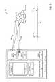
- FIG. 1schematically shows an example time-of-flight (TOF) camera in an example operating environment according to an embodiment of the present disclosure.
- TOFtime-of-flight
- FIG. 2schematically shows an example light-sensitive pixel included in a TOF camera according to an embodiment of the present disclosure.
- FIG. 3shows a method for operating a TOF camera according to an embodiment of the present disclosure.
- FIG. 4schematically shows a timing diagram for operating a TOF camera according to an embodiment of the present disclosure.
- FIG. 5shows a method for generating a normalization factor for a TOF camera according to an embodiment of the present disclosure.
- FIG. 6schematically shows another timing diagram for operating a TOF camera according to an embodiment of the present disclosure.
- Time-of-flight (TOF) camerascapture distance data.
- a three-dimensional image of an object captured by a TOF cameramay be generated based on the distance data collected.
- light pulses of any suitable wavelengthe.g., one or more wavelengths in an infrared, near infrared, visible, and/or ultraviolet region
- the image light pulsesilluminate and are reflected by the object.
- the return image lightis received at a photosensitive surface of the TOF camera.
- the TOF cameramay estimate the distance of various features of the object from the camera. Because light is typically returned relatively sooner from a near feature than from a far feature, time-dependent measurement and quantification of the return image light may provide distance information about the object's features.
- TOF camerasperform the time-dependent measurement by a “range gating” technique.
- range gatingcollection of light at the photosurface is divided (or “gated”) into plural discrete gating events of known duration.
- the TOF cameramay better distinguish return image light from ambient light, potentially improving the accuracy of the distance data.
- some TOF camerasmay intermittently transmit pulses of normalization light that are reflected from the object and collected at the TOF camera.
- the collected return normalization light measurementmay be used to calibrate the target object's reflectivity light from the light collected during the gated time periods.
- image light and normalization lightare often imaged in different frames and acquired at different times.
- the acquisition times for the two eventsmay be separated by a delay time at least equal to a time for reading and resetting each frame.
- the delay timemay cause a mismatch where the same pixel receives return image light and return normalization light from different features of an object or scene rather than from the same feature. Mismatches may also result from situations where the same pixel registers return image light and return normalization light from the same feature at different distances from the camera.
- the distance estimation derived from a mismatchmay be faulty.
- the gated time periodsmay have very short durations that may result in an inaccurate distance estimation.
- Light pulse widths, the short durations of exposure periods, and typical quantum efficiencies on the order of about 10% that characterize conventional photosurfaces used to acquire measurements of gated lightmay result in relatively large errors in the measurements due to shot noise.
- Other distance estimation errorsmay result from reduction in the modulation ratio between the on and off states of the photosurface.
- various embodiments of light-sensitive pixels for TOF cameras and methods for operating such pixelsare provided herein that reduce or substantially eliminate delay times between successive gating time periods and/or normalization time periods, such that the accuracy of the distance estimation may be comparatively increased.
- FIG. 1schematically shows an example operating environment 100 for an embodiment of a TOF camera 104 .
- TOF camera 104is configured to provide image and distance information for object 102 within a predetermined distance range 134 .
- Distance range 134includes the region of space in which distance information may be accurately generated by TOF camera 104 .
- Boundaries for distance range 134are illustrated as a near end point 136 and a far end point 138 .
- the boundariesare defined by pulse and gate widths and delay between a time at which a pulse is transmitted and a subsequent time at which the camera is gated on for a gated time period.
- TOF camera 104includes a light emitter 106 for emitting pulses of light 130 that illuminates object 102 .
- light emitter 106may be controlled by a light emission module 116 .
- light emission module 116may control one or more of pulse timing, pulse width, and wavelength of light 130 .
- Photosurface 120comprises one or more light-sensitive pixels (not shown) for collecting return image light 132 .
- light collector 108may be controlled by a light collection module 118 .
- light collection module 118may control one or more of light gating events and light normalization events for light-sensitive pixels included in photosurface 120 .
- distance estimation module 124receives return image light and/or normalization light information from light collector 108 .
- Distance estimation module 124generates distance information about object 102 based on light emission information and light collection information provided by light emission module 116 and light collection module 118 .
- photosurface 120includes one or more light-sensitive pixels for collecting return image light and return normalization light.
- FIG. 2schematically shows a single light-sensitive pixel 200 .
- light-sensitive pixel 200includes a substrate 202 in which a cavity 206 is formed.
- cavity 206may be approximately 4 microns wide and approximately 2 microns deep.
- substrate 202may be fabricated from an insulating material.
- Example materials for substrate 202include, but are not limited to, undoped silicate glass (USG) and doped or undoped silicon, though it will be appreciated that any suitable substrate material may be employed without departing from the scope of the present disclosure.
- FIG. 2also depicts an optical component 204 disposed above cavity 206 .
- optical component 204hermetically seals cavity 206 .
- Seal 208may be formed from any suitable material; for example, in some embodiments, seal 208 may include a soft metal.
- One example material for seal 208may include indium, though it will be appreciated that seal 208 may include various suitable low-volatility polymeric materials in some embodiments.
- FIG. 2depicts optical component 204 as sealing cavity 206 for a single light-sensitive pixel 200 , it will be appreciated that in some embodiments, two or more light-sensitive pixels 200 may be sealed as a unit by optical component 204 and seal 208 .
- Optical component 204includes a photoelectric cathode 210 for generating photoelectrons 216 responsive to light incident on light-sensitive pixel 200 .
- Optical component 204may be optically transparent in some embodiments, so that light in a visible range of wavelengths may pass through optical component 204 . Additionally or alternatively, in some embodiments, optical component 204 may be configured to allow light in an infrared and/or ultraviolet range of wavelengths to pass.
- photoelectric cathode 210may include a layer of photoelectric material configured to generate photoelectrons 216 in response to incident return image light 132 .
- Example photoelectric materialsinclude, but are not limited to, GaAs, CsO, and AlGaAs. However, it will be appreciated that any suitable photoelectric material may be employed without departing from the scope of the present disclosure.
- cavity 206may be evacuated so that photoelectrons 216 have a sufficiently long mean free path to reach a portion of cavity 206 wherein a plurality of anodes 212 are disposed.
- photoelectric cathode 210is included in cavity 206 and comprises a layer of photoelectric material deposited on an evacuated side of optical component 204 .
- cavity 206includes a plurality of anodes 212 for collecting photoelectrons 216 generated at photoelectric cathode 210 .
- each anode 212includes an electrode 214 electrically connected to a collector circuit 218 .
- a respective collector circuit 218collects photoelectrons 216 and outputs a resulting charge to the light collection module via output node 226 .
- Electrodes 214are spaced from photocathode 210 according to one or more predetermined design parameters for light-sensitive pixel 200 . It is believed that increasing the spacing between electrodes 214 and photocathode 210 may reduce capacitive coupling between electrodes 214 and photocathode 210 , potentially increasing a speed at which light-sensitive pixel 200 may switch between each anode 212 . Further, as described above, increasing the spacing between electrodes 214 and photocathode 210 may also reduce a probability that photoelectrons 216 may reach electrodes 214 , potentially decreasing the charge yield at electrodes 214 .
- the charge yieldmay also potentially be reduced as the spacing between electrodes 214 and photocathode 210 is reduced, as a smaller portion of photoelectrons 216 emitted from photocathode 210 may have a suitable trajectory to reach each electrode 214 .
- suitable spacingmay be influenced by an electrode bias voltage during collection, photocathode cross-section, and vacuum level within cavity 206 .
- photocathode 210may be 2 microns from electrodes 214 .
- each collector circuit 218includes a gate input node 222 for biasing respective electrode 214 .
- FIG. 2depicts a gate capacitor 224 by which a positive charge may be induced at electrode 214 relative to photocathode 210 .
- Electrode 214generates a field that attracts photoelectrons 216 for collection.
- Applying power from power supply 238 to selector node 228selectively switches current flow through an individual collector circuit 218 .
- a particular collector circuit 218may be selectively activated in response to a circuit selection signal received from a light collection module (e.g., light collection module 118 of FIG. 1 ) and power received from power supply 238 .
- a light collection modulee.g., light collection module 118 of FIG. 1
- powering selector node 228turns on output transistor 230 , connecting output node 226 to electrode 214 via amplifier 232 .
- charge collected at electrode 214may be amplified and output from collector circuit 218 .
- the number of photoelectrons 216 generated at photocathode 210is proportional to the amount of return image light 132 received at photocathode 210
- the amount of charge collected at electrode 214 and output from collector circuit 218is also proportionate to the amount of return image light 132 received at light-sensing pixel 200 .
- collector circuit 218may also include a reset node 234 for resetting anode 212 .
- a reset signal to reset node 234turns on reset transistor 236 , resetting anode 212 to a supply voltage of power supply 238 .
- light-sensitive pixel 200may be fabricated in any suitable manner without departing from the scope of the present disclosure.
- light-sensitive pixel 200may be fabricated on a silicon substrate.
- one or more subtractive processesmay be employed to pattern and etch cavity 206 on a first side of the silicon substrate.
- a through-silicon viamay be etched connecting the first side of the silicon substrate to a second, opposite side of the silicon substrate, on which a portion of collector circuit 218 may be formed via various deposition and patterning techniques.
- a suitable metallization processmay be used to fill the through-silicon via and form electrodes 214 .
- the first and second sides of the silicon substratemay refer to two silicon substrates initially separated and subsequently bonded via a suitable substrate bonding technique.
- a suitable deposition processmay be used to form photocathode 210 on optical component 204 , which may then be bonded to the silicon substrate above cavity 206 .
- FIG. 3shows a method 300 for operating a time-of-flight camera in accordance with embodiments of the present disclosure. While method 300 may be used to operate the hardware embodiments described above, it will be appreciated that method 300 may be used to operate any compatible time-of-flight camera including any compatible plural anode light-sensitive pixel.
- method 300comprises, at 302 , emitting an image light pulse from a light source of the camera, the light source configured to illuminate an object feature.
- FIG. 4shows an example time sequence 400 depicting an image light pulse 402 emitted from a light emitter and gating events including return image light collection phases performed by a plurality of anodes included in a single light-sensitive pixel.
- method 300comprises, during a first collection phase, collecting a first portion of return image light at a first anode of a light-sensitive pixel, the return image light comprising image light reflected by the object feature illuminated at least in part by the image light pulse.
- a first portion of return image lightis collected during first return image light collection phase 405 A by turning the first anode on during first return image light collection phase 405 A.
- a start time for first return image light collection phase 405 Amay be based on a predetermined near end point of a distance range for the TOF camera.
- start time 406corresponds to the near end point of a boundary of the distance range for the TOF camera.
- start time 406is set to follow image light pulse 402 by a duration that corresponds to the estimated round trip time of image light pulse 402 from the light emitter to an object at near end point 136 of FIG. 1 and back to the collector.
- method 300comprises, during a second collection phase, collecting a second portion of the return image light at a second anode of the light-sensitive pixel.
- a second portion of return image lightis collected during second return image light collection phase 405 B by turning the second anode on during the second return image light collection phase 405 B.
- an end time for a second return image light collection phasemay be based on a predetermined far end point of the distance range.
- end time 408corresponds to the far end point of the distance range for the TOF camera.
- end time 408is set to follow image light pulse 402 by a duration that corresponds to the estimated round trip time of image light pulse 402 from the light emitter to an object at far end point 138 of FIG. 1 and back to the collector.
- the last collection phasemay immediately follow the first collection phase.
- the first anodeis turned off and the second anode is turned on concurrently at anode switch time 410 .
- return image lightmay be collected without interruption between start time 406 and end time 408 . While the example shown in FIG. 4 depicts two return image light collection phases, it will be appreciated that any suitable number of gating time periods may be employed without departing from the scope of the present disclosure.
- method 300comprises normalizing the first and second portions of the return image light with a normalization factor.
- the normalization factormay account for the reflectivity of the object.
- the normalizationmay be accomplished by dividing one of the collecting phases by the sum of both collecting phases.
- the normalization factormay be generated dynamically at each depth frame by the TOF camera.
- FIG. 5shows a method 500 for dynamically generating a reflectivity normalization factor at each depth frame.
- Method 500comprises, at 502 , emitting a normalization light pulse.
- a normalization light pulse 403is emitted by the light emitter after emission of image light pulse 402 .
- normalization light pulse 403 and image light pulse 402have the same pulse width and intensity.
- the amount of lightmay be quantitatively the same between the two light pulses. This may provide an approach to scaling the amount of light collected during the return image light collection phases.
- method 500comprises, at a third anode of the light-sensitive pixel (e.g., anode 212 C of FIG. 2 ), collecting all of the return normalization light.
- the third anodeis turned on during return normalization light collection phase 413 .
- FIG. 4shows return normalization light collection phase 413 with reference to start time 406 and end time 408 , so that all of the return normalization light 412 may be collected, even if portions of the object being imaged are outside of the boundaries of the camera's range.
- method 500comprises, at 506 , defining the reflectivity normalization factor based on the return normalization light collected.
- the reflectivity normalization factormay be defined as the total return normalization light 412 collected during return normalization light collection phase 413 . This process may be dynamically repeated at each depth frame.
- Method 300may additionally or alternatively comprise compensating for ambient light to comparatively reduce measurement errors resulting in part from the influence of ambient light.
- ambient light compensationmay be achieved by collecting ambient light during a time when a light pulse is not emitted. In this way, the relative amount of ambient light present may be determined. Ambient light compensation is not always required. For example, when the integration time is short enough, the ambient light is low enough, and the accuracy requirements are relaxed enough, there might not be a need to compensate for the ambient light.
- ambient light compensationis performed, a signal is collected without operating the illumination. This can be done using any suitable approach, including using anode 212 C of FIG. 2 .
- FIG. 6shows an example time sequence 700 depicting a light pulse 702 emitted from a light emitter and various return image light collection phases and ambient light collection phases during which three anodes in a single light-sensitive pixel are sequentially activated to collected portions of return image light and portions of ambient light.
- anode 3(for example, anode 212 C of FIG. 2 ) is activated during ambient light collection phase 715 A to collect a first portion of ambient light 714 A.
- anode 3is turned off and anode 1 (for example, anode 212 A of FIG. 2 ) is turned on coincident with the start of return image light collection phase 705 A.
- the transition between anode 3 and anode 1is immediate, so that there is no gap in light collection at the pixel.
- anode switching time 710 Amay be based on a predetermined near end point of a distance range for the time-of-flight camera. In the example shown in FIG. 6 , anode switching time 710 A corresponds to the near end point of a boundary of the distance range for the TOF camera.
- anode 1is turned off and anode 2 (for example, anode 212 B of FIG. 2 ) is turned on.
- anode 2for example, anode 212 B of FIG. 2
- the transition between anode 1 and anode 2is immediate, so that there is no gap in light collection at the pixel, potentially avoiding mismatches.
- FIG. 6also depicts that, at anode switching time 710 C, anode 2 is turned off and anode 3 is turned on. Again, in the example shown in FIG. 6 , the transition between anode 2 and anode 3 is immediate, so that there is no gap in light collection at the pixel, potentially avoiding mismatches.
- anode switching time 710 Cmay be based on a predetermined far end point of a distance range for the time-of-flight camera. In the example shown in FIG. 6 , anode switching time 710 C corresponds to the far end point of the distance range for the TOF camera.
- the third anodecollects a first portion of the ambient light immediately before first return image light collection phase 705 A and a second portion of the ambient light immediately after the last return image light collection phase, shown in FIG. 6 as return image light collection phase 705 B.
- the sum of return image light collection phases 705 A and 705 Bcollects all of return image light and portions of the ambient light 714 B and 714 C.
- ambient light collection phases 715 A and 715 Bcollected portions of ambient light 714 A and 714 D without collecting any return image light
- subtraction of the ambient light collected in ambient light collection phases 715 A and 715 D from the light collected in return image light collection phases 705 A and 705 Bmay remove approximately all of the ambient light.
- a separate normalization light pulse and return normalization light collection phasemay not be needed.
- a reflectivity normalization factormay be generated by summing the light collected in return image light collection phases 705 A and 705 B of FIG. 6 .
- method 300comprises, at 314 , estimating a distance to the object feature based on one or more of the normalized portions. For example, in embodiments where the return image light is collected in two gating time periods (like return image light collection phases 405 A and 405 B in FIG. 4 and return image light collection phases 705 B and 705 C in FIG. 6 ), a relative quantitative comparison of the two gating time periods may indicate a location of the object within the distance range of the camera.
- distance (D)may be estimated as a function of a first portion of return image light (R 1 ), a second portion of return image light (R 2 ), a total amount of light returned (R 1 +R 2 ), a distance range (L), and a fixed constant (c) that depends on the electronic delay of the camera system, as shown in Equation 1 below.
- the formulamay be:
- F 1 and F 2are functions with unique and monotonic values over the practical range.
- F 1 and F 2may be a practical case when pulse shapes are not as symmetrical as shown in FIG. 4 and FIG. 6 , so the functions can be close to linear over the practical range, have double slope linearity, or other variations.
- the above described methods and processesmay be tied to a computing system including one or more computers.
- the methods and processes described hereinmay be implemented as a computer application, computer service, computer API, computer library, and/or other computer program product.
- TOF camera 104includes a logic subsystem 110 and a data-holding subsystem 112 .
- TOF camera 104may optionally include a display subsystem, communication subsystem, and/or other components not shown in FIG. 1 .
- the TOF cameramay be configured to cooperate with an off-board logic subsystem and/or an off-board data-holding subsystem.
- Logic subsystem 110may include one or more physical devices configured to execute one or more instructions.
- the logic subsystemmay be configured to execute one or more instructions that are part of one or more applications, services, programs, routines, libraries, objects, components, data structures, or other logical constructs.
- Such instructionsmay be implemented to perform a task, implement a data type, transform the state of one or more devices, or otherwise arrive at a desired result.
- Logic subsystem 110may include one or more processors that are configured to execute software instructions. Additionally or alternatively, logic subsystem 110 may include one or more hardware or firmware logic machines configured to execute hardware or firmware instructions. Processors of the logic subsystem may be single-core or multi-core, and the programs executed thereon may be configured for parallel or distributed processing. Logic subsystem 110 may optionally include individual components that are distributed throughout two or more devices, which may be remotely located and/or configured for coordinated processing. One or more aspects of logic subsystem 110 may be virtualized and executed by remotely accessible networked computing devices configured in a cloud computing configuration.
- Data-holding subsystem 112may include one or more physical, non-transitory, devices configured to hold data and/or instructions executable by the logic subsystem to implement the herein described methods and processes. When such methods and processes are implemented, the state of data-holding subsystem 112 may be transformed (e.g., to hold different data).
- data-holding subsystem 112includes one or more physical, non-transitory devices.
- aspects of the instructions described hereinmay be propagated in a transitory fashion by a pure signal (e.g., an electromagnetic signal, an optical signal, etc.) that is not held by a physical device for at least a finite duration.
- a pure signale.g., an electromagnetic signal, an optical signal, etc.
- data and/or other forms of information pertaining to the present disclosuremay be propagated by a pure signal.
- modulemay be used to describe an aspect of TOF camera 104 that is implemented to perform one or more particular functions.
- a module, program, or enginemay be instantiated via logic subsystem 110 executing instructions held by data-holding subsystem 112 .
- different modules, programs, and/or enginesmay be instantiated from the same application, service, code block, object, library, routine, API, function, etc.
- the same module, program, and/or enginemay be instantiated by different applications, services, code blocks, objects, routines, APIs, functions, etc.
- moduleprogram
- engineare meant to encompass individual or groups of executable files, data files, libraries, drivers, scripts, database records, etc.
Landscapes
- Engineering & Computer Science (AREA)
- Physics & Mathematics (AREA)
- Computer Networks & Wireless Communication (AREA)
- General Physics & Mathematics (AREA)
- Radar, Positioning & Navigation (AREA)
- Remote Sensing (AREA)
- Electromagnetism (AREA)
- Measurement Of Optical Distance (AREA)
- Optical Radar Systems And Details Thereof (AREA)
Abstract
Description
Time-of-flight (TOF) cameras collect distance data from a scene. However, it can be difficult to collect accurate distance data from moving objects.
A light-sensitive pixel includes an evacuated cavity formed in an insulating substrate. The light-sensitive pixel further includes a photoelectric cathode for generating electrons responsive to light incident on the light-sensitive pixel. The photoelectric cathode is located in the evacuated cavity. The light-sensitive pixel also includes a plurality of anodes for collecting electrons generated at the photoelectric cathode.
This Summary is provided to introduce a selection of concepts in a simplified form that are further described below in the Detailed Description. This Summary is not intended to identify key features or essential features of the claimed subject matter, nor is it intended to be used to limit the scope of the claimed subject matter. Furthermore, the claimed subject matter is not limited to implementations that solve any or all disadvantages noted in any part of this disclosure.
Time-of-flight (TOF) cameras capture distance data. Thus, a three-dimensional image of an object captured by a TOF camera may be generated based on the distance data collected. In a typical TOF camera, light pulses of any suitable wavelength (e.g., one or more wavelengths in an infrared, near infrared, visible, and/or ultraviolet region) are transmitted from the TOF camera to an object. The image light pulses illuminate and are reflected by the object. The return image light is received at a photosensitive surface of the TOF camera. By measuring the time at which the return image light is received at the photosensitive surface, the TOF camera may estimate the distance of various features of the object from the camera. Because light is typically returned relatively sooner from a near feature than from a far feature, time-dependent measurement and quantification of the return image light may provide distance information about the object's features.
It can be more difficult to generate intense light pulses for illuminating the distant object than to generate a train of light pulses comparatively less intense. Thus, some TOF cameras perform the time-dependent measurement by a “range gating” technique. In typical range gating approaches, collection of light at the photosurface is divided (or “gated”) into plural discrete gating events of known duration. By integrating the light received from multiple pulses at the photosurface, the TOF camera may better distinguish return image light from ambient light, potentially improving the accuracy of the distance data.
Further, some TOF cameras may intermittently transmit pulses of normalization light that are reflected from the object and collected at the TOF camera. The collected return normalization light measurement may be used to calibrate the target object's reflectivity light from the light collected during the gated time periods.
However, a number of factors can adversely affect the accuracy of the distance measurements described above. For example, image light and normalization light are often imaged in different frames and acquired at different times. The acquisition times for the two events may be separated by a delay time at least equal to a time for reading and resetting each frame. For an object in motion, the delay time may cause a mismatch where the same pixel receives return image light and return normalization light from different features of an object or scene rather than from the same feature. Mismatches may also result from situations where the same pixel registers return image light and return normalization light from the same feature at different distances from the camera.
Consequently, the distance estimation derived from a mismatch may be faulty. Further, for some TOF camera systems, the gated time periods may have very short durations that may result in an inaccurate distance estimation. Light pulse widths, the short durations of exposure periods, and typical quantum efficiencies on the order of about 10% that characterize conventional photosurfaces used to acquire measurements of gated light, may result in relatively large errors in the measurements due to shot noise. Other distance estimation errors may result from reduction in the modulation ratio between the on and off states of the photosurface.
Accordingly, various embodiments of light-sensitive pixels for TOF cameras and methods for operating such pixels are provided herein that reduce or substantially eliminate delay times between successive gating time periods and/or normalization time periods, such that the accuracy of the distance estimation may be comparatively increased.
As shown inFIG. 1 ,TOF camera 104 includes alight emitter 106 for emitting pulses oflight 130 that illuminatesobject 102. In some embodiments,light emitter 106 may be controlled by alight emission module 116. For example,light emission module 116 may control one or more of pulse timing, pulse width, and wavelength oflight 130.
In the example shown inFIG. 1 ,distance estimation module 124 receives return image light and/or normalization light information fromlight collector 108.Distance estimation module 124 generates distance information aboutobject 102 based on light emission information and light collection information provided bylight emission module 116 andlight collection module 118.
As described above, photosurface120 includes one or more light-sensitive pixels for collecting return image light and return normalization light.FIG. 2 schematically shows a single light-sensitive pixel 200. As shown in the example depicted inFIG. 2 , light-sensitive pixel 200 includes asubstrate 202 in which acavity 206 is formed. In one non-limiting example,cavity 206 may be approximately 4 microns wide and approximately 2 microns deep.
In some embodiments,substrate 202 may be fabricated from an insulating material. Example materials forsubstrate 202 include, but are not limited to, undoped silicate glass (USG) and doped or undoped silicon, though it will be appreciated that any suitable substrate material may be employed without departing from the scope of the present disclosure.
The example shown inFIG. 2 also depicts anoptical component 204 disposed abovecavity 206. In conjunction withseal 208,optical component 204 hermeticallyseals cavity 206.Seal 208 may be formed from any suitable material; for example, in some embodiments,seal 208 may include a soft metal. One example material forseal 208 may include indium, though it will be appreciated thatseal 208 may include various suitable low-volatility polymeric materials in some embodiments. While the example shown inFIG. 2 depictsoptical component 204 as sealingcavity 206 for a single light-sensitive pixel 200, it will be appreciated that in some embodiments, two or more light-sensitive pixels 200 may be sealed as a unit byoptical component 204 andseal 208.
In some embodiments,photoelectric cathode 210 may include a layer of photoelectric material configured to generatephotoelectrons 216 in response to incidentreturn image light 132. Example photoelectric materials include, but are not limited to, GaAs, CsO, and AlGaAs. However, it will be appreciated that any suitable photoelectric material may be employed without departing from the scope of the present disclosure. In such embodiments,cavity 206 may be evacuated so thatphotoelectrons 216 have a sufficiently long mean free path to reach a portion ofcavity 206 wherein a plurality of anodes212 are disposed. In the example shown inFIG. 2 ,photoelectric cathode 210 is included incavity 206 and comprises a layer of photoelectric material deposited on an evacuated side ofoptical component 204.
As described above,cavity 206 includes a plurality of anodes212 for collectingphotoelectrons 216 generated atphotoelectric cathode 210. In the example shown inFIG. 2 , each anode212 includes anelectrode 214 electrically connected to acollector circuit 218. In response to selection of a particular anode212 bylight collection module 118 ofFIG. 1 , arespective collector circuit 218 collectsphotoelectrons 216 and outputs a resulting charge to the light collection module viaoutput node 226.
In the example shown inFIG. 2 , eachcollector circuit 218 includes agate input node 222 for biasingrespective electrode 214. For example,FIG. 2 depicts agate capacitor 224 by which a positive charge may be induced atelectrode 214 relative tophotocathode 210.Electrode 214 generates a field that attractsphotoelectrons 216 for collection. Applying power frompower supply 238 toselector node 228 selectively switches current flow through anindividual collector circuit 218. Thus, in the embodiment shown inFIG. 2 , aparticular collector circuit 218 may be selectively activated in response to a circuit selection signal received from a light collection module (e.g.,light collection module 118 ofFIG. 1 ) and power received frompower supply 238.
As shown in the example depicted inFIG. 2 , poweringselector node 228 turns onoutput transistor 230, connectingoutput node 226 toelectrode 214 viaamplifier 232. Thus, charge collected atelectrode 214 may be amplified and output fromcollector circuit 218. Because the number ofphotoelectrons 216 generated atphotocathode 210 is proportional to the amount of return image light132 received atphotocathode 210, the amount of charge collected atelectrode 214 and output fromcollector circuit 218 is also proportionate to the amount of return image light132 received at light-sensing pixel 200.
In some embodiments,collector circuit 218 may also include areset node 234 for resetting anode212. In the example shown inFIG. 2 , application of a reset signal to resetnode 234 turns onreset transistor 236, resetting anode212 to a supply voltage ofpower supply 238.
It will be appreciated that light-sensitive pixel 200 may be fabricated in any suitable manner without departing from the scope of the present disclosure. For example, in some embodiments, light-sensitive pixel 200 may be fabricated on a silicon substrate. In such embodiments, one or more subtractive processes may be employed to pattern andetch cavity 206 on a first side of the silicon substrate. Further, a through-silicon via may be etched connecting the first side of the silicon substrate to a second, opposite side of the silicon substrate, on which a portion ofcollector circuit 218 may be formed via various deposition and patterning techniques. In some embodiments, a suitable metallization process may be used to fill the through-silicon via andform electrodes 214. It will be appreciated that, in some embodiments, the first and second sides of the silicon substrate may refer to two silicon substrates initially separated and subsequently bonded via a suitable substrate bonding technique. Finally, as explained above, a suitable deposition process may be used to formphotocathode 210 onoptical component 204, which may then be bonded to the silicon substrate abovecavity 206.
As shown inFIG. 3 ,method 300 comprises, at302, emitting an image light pulse from a light source of the camera, the light source configured to illuminate an object feature. For example,FIG. 4 shows anexample time sequence 400 depicting an imagelight pulse 402 emitted from a light emitter and gating events including return image light collection phases performed by a plurality of anodes included in a single light-sensitive pixel.
Turning back toFIG. 3 , at304,method 300 comprises, during a first collection phase, collecting a first portion of return image light at a first anode of a light-sensitive pixel, the return image light comprising image light reflected by the object feature illuminated at least in part by the image light pulse. In the example shown inFIG. 4 , a first portion of return image light is collected during first return imagelight collection phase 405A by turning the first anode on during first return imagelight collection phase 405A.
In some embodiments, a start time for first return imagelight collection phase 405A may be based on a predetermined near end point of a distance range for the TOF camera. In the example shown inFIG. 4 , starttime 406 corresponds to the near end point of a boundary of the distance range for the TOF camera. In particular, starttime 406 is set to follow imagelight pulse 402 by a duration that corresponds to the estimated round trip time of imagelight pulse 402 from the light emitter to an object atnear end point 136 ofFIG. 1 and back to the collector.
Turning back toFIG. 3 , at306,method 300 comprises, during a second collection phase, collecting a second portion of the return image light at a second anode of the light-sensitive pixel. In the example shown inFIG. 4 , a second portion of return image light is collected during second return imagelight collection phase 405B by turning the second anode on during the second return imagelight collection phase 405B.
In some embodiments, an end time for a second return image light collection phase may be based on a predetermined far end point of the distance range. In the example shown inFIG. 4 ,end time 408 corresponds to the far end point of the distance range for the TOF camera. In particular,end time 408 is set to follow imagelight pulse 402 by a duration that corresponds to the estimated round trip time of imagelight pulse 402 from the light emitter to an object atfar end point 138 ofFIG. 1 and back to the collector.
In some embodiments, the last collection phase may immediately follow the first collection phase. In the example shown inFIG. 4 , the first anode is turned off and the second anode is turned on concurrently atanode switch time 410. By immediately transitioning between anodes, return image light may be collected without interruption betweenstart time 406 and endtime 408. While the example shown inFIG. 4 depicts two return image light collection phases, it will be appreciated that any suitable number of gating time periods may be employed without departing from the scope of the present disclosure.
Continuing withFIG. 3 , at308,method 300 comprises normalizing the first and second portions of the return image light with a normalization factor. The normalization factor may account for the reflectivity of the object. The normalization may be accomplished by dividing one of the collecting phases by the sum of both collecting phases.
In some embodiments, the normalization factor may be generated dynamically at each depth frame by the TOF camera.FIG. 5 shows amethod 500 for dynamically generating a reflectivity normalization factor at each depth frame.Method 500 comprises, at502, emitting a normalization light pulse.
In the example shown inFIG. 4 , anormalization light pulse 403 is emitted by the light emitter after emission of imagelight pulse 402. As depicted inFIG. 4 ,normalization light pulse 403 and imagelight pulse 402 have the same pulse width and intensity. Thus, the amount of light may be quantitatively the same between the two light pulses. This may provide an approach to scaling the amount of light collected during the return image light collection phases.
Returning toFIG. 5 , at504,method 500 comprises, at a third anode of the light-sensitive pixel (e.g.,anode 212C ofFIG. 2 ), collecting all of the return normalization light. In the example shown inFIG. 4 , the third anode is turned on during return normalizationlight collection phase 413. For illustrative purposes,FIG. 4 shows return normalizationlight collection phase 413 with reference to starttime 406 and endtime 408, so that all of thereturn normalization light 412 may be collected, even if portions of the object being imaged are outside of the boundaries of the camera's range.
Continuing withFIG. 5 ,method 500 comprises, at506, defining the reflectivity normalization factor based on the return normalization light collected. For example, in some embodiments, the reflectivity normalization factor may be defined as the totalreturn normalization light 412 collected during return normalizationlight collection phase 413. This process may be dynamically repeated at each depth frame.
In the example shown inFIG. 6 , anode3 (for example,anode 212C ofFIG. 2 ) is activated during ambientlight collection phase 715A to collect a first portion ofambient light 714A. Atanode switching time 710A,anode 3 is turned off and anode1 (for example,anode 212A ofFIG. 2 ) is turned on coincident with the start of return imagelight collection phase 705A. In the example shown inFIG. 6 , the transition betweenanode 3 andanode 1 is immediate, so that there is no gap in light collection at the pixel.
In some embodiments,anode switching time 710A may be based on a predetermined near end point of a distance range for the time-of-flight camera. In the example shown inFIG. 6 ,anode switching time 710A corresponds to the near end point of a boundary of the distance range for the TOF camera.
As shown inFIG. 6 , atanode switching time 710B,anode 1 is turned off and anode2 (for example,anode 212B ofFIG. 2 ) is turned on. In the example shown inFIG. 6 , the transition betweenanode 1 andanode 2 is immediate, so that there is no gap in light collection at the pixel, potentially avoiding mismatches.
The example shown inFIG. 6 also depicts that, atanode switching time 710C,anode 2 is turned off andanode 3 is turned on. Again, in the example shown inFIG. 6 , the transition betweenanode 2 andanode 3 is immediate, so that there is no gap in light collection at the pixel, potentially avoiding mismatches.
In some embodiments,anode switching time 710C may be based on a predetermined far end point of a distance range for the time-of-flight camera. In the example shown inFIG. 6 ,anode switching time 710C corresponds to the far end point of the distance range for the TOF camera.
In the example shown inFIG. 6 , the third anode collects a first portion of the ambient light immediately before first return imagelight collection phase 705A and a second portion of the ambient light immediately after the last return image light collection phase, shown inFIG. 6 as return imagelight collection phase 705B. As a consequence, the sum of return image light collection phases705A and705B collects all of return image light and portions of theambient light ambient light
A separate normalization light pulse and return normalization light collection phase may not be needed. For example, a reflectivity normalization factor may be generated by summing the light collected in return image light collection phases705A and705B ofFIG. 6 .
Continuing withFIG. 3 ,method 300 comprises, at314, estimating a distance to the object feature based on one or more of the normalized portions. For example, in embodiments where the return image light is collected in two gating time periods (like return image light collection phases405A and405B inFIG. 4 and return image light collection phases705B and705C inFIG. 6 ), a relative quantitative comparison of the two gating time periods may indicate a location of the object within the distance range of the camera. Thus, in one example, distance (D) may be estimated as a function of a first portion of return image light (R1), a second portion of return image light (R2), a total amount of light returned (R1+R2), a distance range (L), and a fixed constant (c) that depends on the electronic delay of the camera system, as shown inEquation 1 below.
The above is an ideal case with linear behavior. In some cases, the formula may be:
Or other variations of R1and R2, where F1 and F2 are functions with unique and monotonic values over the practical range. F1 and F2 may be a practical case when pulse shapes are not as symmetrical as shown inFIG. 4 andFIG. 6 , so the functions can be close to linear over the practical range, have double slope linearity, or other variations.
In some embodiments, the above described methods and processes may be tied to a computing system including one or more computers. In particular, the methods and processes described herein may be implemented as a computer application, computer service, computer API, computer library, and/or other computer program product.
Returning toFIG. 1 ,TOF camera 104 includes alogic subsystem 110 and a data-holdingsubsystem 112.TOF camera 104 may optionally include a display subsystem, communication subsystem, and/or other components not shown inFIG. 1 . In other embodiments, the TOF camera may be configured to cooperate with an off-board logic subsystem and/or an off-board data-holding subsystem.
Data-holdingsubsystem 112 may include one or more physical, non-transitory, devices configured to hold data and/or instructions executable by the logic subsystem to implement the herein described methods and processes. When such methods and processes are implemented, the state of data-holdingsubsystem 112 may be transformed (e.g., to hold different data).
It is to be appreciated that data-holdingsubsystem 112 includes one or more physical, non-transitory devices. In contrast, in some embodiments aspects of the instructions described herein may be propagated in a transitory fashion by a pure signal (e.g., an electromagnetic signal, an optical signal, etc.) that is not held by a physical device for at least a finite duration. Furthermore, data and/or other forms of information pertaining to the present disclosure may be propagated by a pure signal.
The terms “module,” “program,” and “engine” may be used to describe an aspect ofTOF camera 104 that is implemented to perform one or more particular functions. In some cases, such a module, program, or engine may be instantiated vialogic subsystem 110 executing instructions held by data-holdingsubsystem 112. It is to be understood that different modules, programs, and/or engines may be instantiated from the same application, service, code block, object, library, routine, API, function, etc. Likewise, the same module, program, and/or engine may be instantiated by different applications, services, code blocks, objects, routines, APIs, functions, etc. The terms “module,” “program,” and “engine” are meant to encompass individual or groups of executable files, data files, libraries, drivers, scripts, database records, etc.
It is to be understood that the configurations and/or approaches described herein are exemplary in nature, and that these specific embodiments or examples are not to be considered in a limiting sense, because numerous variations are possible. The specific routines or methods described herein may represent one or more of any number of processing strategies. As such, various acts illustrated may be performed in the sequence illustrated, in other sequences, in parallel, or in some cases omitted. Likewise, the order of the above-described processes may be changed.
The subject matter of the present disclosure includes all novel and nonobvious combinations and subcombinations of the various processes, systems and configurations, and other features, functions, acts, and/or properties disclosed herein, as well as any and all equivalents thereof.
Claims (19)
1. A time-of-flight light-sensitive pixel in a time-of-flight camera, comprising:
a hermetically sealed evacuated cavity formed in an insulating substrate;
a photoelectric cathode for generating electrons responsive to light incident on the time-of-flight light-sensitive pixel in the time-of-flight camera; and
a plurality of anodes for collecting electrons generated at the photoelectric cathode and passing through the hermetically sealed evacuated cavity.
2. The time-of-flight light-sensitive pixel in the time-of-flight camera ofclaim 1 , wherein the plurality of anodes are configured to, during a first collection phase, collect a first portion of the light incident on the time-of-flight light-sensitive pixel at a first anode of the time-of-flight light-sensitive pixel, and during a second collection phase, collect a second portion of the light incident on the time-of-flight light-sensitive pixel at a second anode of the time-of-flight light-sensitive pixel, the second collection phase immediately following the first collection phase.
3. The time-of-flight light-sensitive pixel in the time-of-flight camera ofclaim 1 , further comprising:
an optically transparent component disposed above the hermetically sealed evacuated cavity; and
a seal for sealing the optically transparent component to the insulating substrate.
4. The time-of-flight light-sensitive pixel in the time-of-flight camera ofclaim 3 , wherein the photoelectric cathode comprises a layer of photoelectric material deposited on an evacuated side of the optically transparent component.
5. The time-of-flight light-sensitive pixel in the time-of-flight camera ofclaim 1 , wherein each anode is electrically connected with a respective collector circuit.
6. The time-of-flight light-sensitive pixel in the time-of-flight camera ofclaim 5 , wherein each collector circuit electrically connected to a particular anode comprises:
a gate input node electrically connected with that particular anode for biasing that particular anode;
an amplifier electrically connected with the gate input node for amplifying current received at that particular anode;
an output node electrically connected to the amplifier for carrying current to a light collection module;
a selector node electrically connected to the amplifier and the output node for selectively switching current flow through the output node; and
a reset node for selectively resetting that particular anode.
7. The time-of-flight light-sensitive pixel in the time-of-flight camera ofclaim 5 , wherein each collector circuit is electrically connected to a power supply configured to selectively activate each of the plurality of anodes individually.
8. The time-of-flight light-sensitive pixel in the time-of-flight camera ofclaim 5 , wherein the hermetically sealed evacuated cavity is formed on a first side of a silicon substrate, and wherein the collector circuits are formed on an opposite side of the silicon substrate, each collector circuit being electrically connected with a particular anode with an interconnect passing through a via.
9. A method for operating a time-of-flight camera, the method comprising:
emitting an image light pulse from a light source of the time-of-flight camera, the light source configured to illuminate an object with image light;
during a first collection phase, collecting a first portion of return image light at a first anode of a light-sensitive pixel, the return image light comprising image light reflected by the object;
during a second collection phase, collecting a second portion of the return image light at a second anode of the light-sensitive pixel;
normalizing the first and second portions of the return image light with a normalization factor; and
estimating a distance to the object based on one or more of the normalized first and second portions of the return image light.
10. The method ofclaim 9 , wherein the second collection phase immediately follows the first collection phase.
11. The method ofclaim 9 , further comprising generating the normalization factor by:
emitting a normalization light pulse from the light source of the time-of-flight camera;
at one of the anodes of the light-sensitive pixel, collecting return normalization light; and
defining the normalization factor based on the return normalization light collected.
12. The method ofclaim 9 , further comprising collecting ambient light at a third anode of the light-sensitive pixel.
13. The method ofclaim 12 , wherein the third anode collects a first portion of the ambient light immediately before the first collection phase and a second portion of the ambient light immediately after the second collection phase.
14. The method ofclaim 9 , wherein a start time for the first collection phase is based on a predetermined near end point of a distance range for the time-of-flight camera and wherein an end time for the second collection phase is based on a predetermined far end point of the distance range.
15. A time-of-flight camera, comprising:
a light source for illuminating an object with image light;
a plurality of time-of-flight light-sensitive pixels for collecting return image light reflected by the object, each time-of-flight light-sensitive pixel comprising:
a photoelectric cathode for generating electrons responsive to return image light incident on a corresponding time-of-flight light-sensitive pixel, and
a plurality of anodes for collecting electrons generated at the photoelectric cathode and passing through a hermetically sealed evacuated cavity between the photoelectric cathode and the plurality of anodes.
16. The time-of-flight camera ofclaim 15 , further comprising a light collection module configured to:
during a first collection phase, collect a first portion of the return image light at a first anode of a corresponding time-of-flight light-sensitive pixel; and
during a second collection phase, collect a second portion of the return image light at a second anode of the corresponding time-of-flight light-sensitive pixel, the second collection phase immediately following the first collection phase.
17. The time-of-flight camera ofclaim 16 , wherein a start time for the first collection phase is based on a predetermined near end point of a distance range for the time-of-flight camera and wherein an end time for a last collection phase is based on a predetermined far end point of the distance range.
18. The time-of-flight camera ofclaim 15 , further comprising a power supply configured to selectively activate each of the plurality of anodes individually.
19. The time-of flight camera ofclaim 16 , wherein each anode is electrically connected with a respective collector circuit, each collector circuit comprising:
a gate input node electrically connected with a particular anode for biasing that particular anode;
an amplifier electrically connected with the gate input node for amplifying current received at that particular anode;
an output node electrically connected to the amplifier for carrying current to the light collection module;
a selector node electrically connected to the amplifier and the output node for selectively switching current flow through the output node; and
a reset node for selectively resetting that particular anode.
Priority Applications (3)
| Application Number | Priority Date | Filing Date | Title |
|---|---|---|---|
| US12/975,174US9823339B2 (en) | 2010-12-21 | 2010-12-21 | Plural anode time-of-flight sensor |
| CN201110431512.XACN102590821B (en) | 2010-12-21 | 2011-12-20 | Plural anode time-of-flight sensor |
| HK12112169.6AHK1171513B (en) | 2010-12-21 | 2012-11-27 | Plural anode time-of-flight sensor |
Applications Claiming Priority (1)
| Application Number | Priority Date | Filing Date | Title |
|---|---|---|---|
| US12/975,174US9823339B2 (en) | 2010-12-21 | 2010-12-21 | Plural anode time-of-flight sensor |
Publications (2)
| Publication Number | Publication Date |
|---|---|
| US20120154573A1 US20120154573A1 (en) | 2012-06-21 |
| US9823339B2true US9823339B2 (en) | 2017-11-21 |
Family
ID=46233880
Family Applications (1)
| Application Number | Title | Priority Date | Filing Date |
|---|---|---|---|
| US12/975,174Active2034-08-03US9823339B2 (en) | 2010-12-21 | 2010-12-21 | Plural anode time-of-flight sensor |
Country Status (2)
| Country | Link |
|---|---|
| US (1) | US9823339B2 (en) |
| CN (1) | CN102590821B (en) |
Cited By (34)
| Publication number | Priority date | Publication date | Assignee | Title |
|---|---|---|---|---|
| US20180053799A1 (en)* | 2015-05-28 | 2018-02-22 | Panasonic Intellectual Property Management Co., Ltd. | Distance-measuring imaging device, distance measuring method of distance-measuring imaging device, and solid-state imaging device |
| US20180236927A1 (en)* | 2017-02-22 | 2018-08-23 | Stmicroelectronics (Research & Development) Limited | Integration of depth map device for adaptive lighting control |
| US10552979B2 (en) | 2017-09-13 | 2020-02-04 | TuSimple | Output of a neural network method for deep odometry assisted by static scene optical flow |
| US10565728B2 (en) | 2018-06-01 | 2020-02-18 | Tusimple, Inc. | Smoothness constraint for camera pose estimation |
| US10671083B2 (en) | 2017-09-13 | 2020-06-02 | Tusimple, Inc. | Neural network architecture system for deep odometry assisted by static scene optical flow |
| US10679074B2 (en) | 2017-03-10 | 2020-06-09 | Tusimple, Inc. | System and method for semantic segmentation using hybrid dilated convolution (HDC) |
| US10762673B2 (en) | 2017-08-23 | 2020-09-01 | Tusimple, Inc. | 3D submap reconstruction system and method for centimeter precision localization using camera-based submap and LiDAR-based global map |
| US10762635B2 (en) | 2017-06-14 | 2020-09-01 | Tusimple, Inc. | System and method for actively selecting and labeling images for semantic segmentation |
| US10816354B2 (en) | 2017-08-22 | 2020-10-27 | Tusimple, Inc. | Verification module system and method for motion-based lane detection with multiple sensors |
| US10942271B2 (en) | 2018-10-30 | 2021-03-09 | Tusimple, Inc. | Determining an angle between a tow vehicle and a trailer |
| US10953880B2 (en) | 2017-09-07 | 2021-03-23 | Tusimple, Inc. | System and method for automated lane change control for autonomous vehicles |
| US10953881B2 (en) | 2017-09-07 | 2021-03-23 | Tusimple, Inc. | System and method for automated lane change control for autonomous vehicles |
| US11009356B2 (en) | 2018-02-14 | 2021-05-18 | Tusimple, Inc. | Lane marking localization and fusion |
| US11010874B2 (en) | 2018-04-12 | 2021-05-18 | Tusimple, Inc. | Images for perception modules of autonomous vehicles |
| US11009365B2 (en) | 2018-02-14 | 2021-05-18 | Tusimple, Inc. | Lane marking localization |
| US11019274B2 (en) | 2018-09-10 | 2021-05-25 | Tusimple, Inc. | Adaptive illumination for a time-of-flight camera on a vehicle |
| US11023742B2 (en) | 2018-09-07 | 2021-06-01 | Tusimple, Inc. | Rear-facing perception system for vehicles |
| US11070756B2 (en) | 2018-01-24 | 2021-07-20 | Tusimple, Inc. | Method, device and system for image acquisition control |
| US11151393B2 (en) | 2017-08-23 | 2021-10-19 | Tusimple, Inc. | Feature matching and corresponding refinement and 3D submap position refinement system and method for centimeter precision localization using camera-based submap and LiDAR-based global map |
| US11292437B2 (en) | 2017-11-16 | 2022-04-05 | Beijing Tusen Weilai Technology Co., Ltd. | System and method for automated cleaning |
| US11295146B2 (en) | 2018-02-27 | 2022-04-05 | Tusimple, Inc. | System and method for online real-time multi-object tracking |
| US11292480B2 (en) | 2018-09-13 | 2022-04-05 | Tusimple, Inc. | Remote safe driving methods and systems |
| US11305782B2 (en) | 2018-01-11 | 2022-04-19 | Tusimple, Inc. | Monitoring system for autonomous vehicle operation |
| US11312334B2 (en) | 2018-01-09 | 2022-04-26 | Tusimple, Inc. | Real-time remote control of vehicles with high redundancy |
| US11500101B2 (en) | 2018-05-02 | 2022-11-15 | Tusimple, Inc. | Curb detection by analysis of reflection images |
| US11701931B2 (en) | 2020-06-18 | 2023-07-18 | Tusimple, Inc. | Angle and orientation measurements for vehicles with multiple drivable sections |
| US11810322B2 (en) | 2020-04-09 | 2023-11-07 | Tusimple, Inc. | Camera pose estimation techniques |
| US11823460B2 (en) | 2019-06-14 | 2023-11-21 | Tusimple, Inc. | Image fusion for autonomous vehicle operation |
| US11853071B2 (en) | 2017-09-07 | 2023-12-26 | Tusimple, Inc. | Data-driven prediction-based system and method for trajectory planning of autonomous vehicles |
| US11932238B2 (en) | 2020-06-29 | 2024-03-19 | Tusimple, Inc. | Automated parking technology |
| US11972690B2 (en) | 2018-12-14 | 2024-04-30 | Beijing Tusen Zhitu Technology Co., Ltd. | Platooning method, apparatus and system of autonomous driving platoon |
| US12099121B2 (en) | 2018-12-10 | 2024-09-24 | Beijing Tusen Zhitu Technology Co., Ltd. | Trailer angle measurement method and device, and vehicle |
| US12135565B2 (en) | 2020-06-26 | 2024-11-05 | Tusimple, Inc. | Adaptive sensor control |
| US12270661B2 (en) | 2018-02-14 | 2025-04-08 | Tusimple, Inc. | Lane marking localization and fusion |
Families Citing this family (5)
| Publication number | Priority date | Publication date | Assignee | Title |
|---|---|---|---|---|
| US8988508B2 (en)* | 2010-09-24 | 2015-03-24 | Microsoft Technology Licensing, Llc. | Wide angle field of view active illumination imaging system |
| US8994867B2 (en) | 2013-03-15 | 2015-03-31 | Samsung Electronics Co., Ltd. | Image sensor, operating method thereof, and device including the image sensor |
| US9866816B2 (en) | 2016-03-03 | 2018-01-09 | 4D Intellectual Properties, Llc | Methods and apparatus for an active pulsed 4D camera for image acquisition and analysis |
| US10302768B2 (en) | 2016-05-09 | 2019-05-28 | Microsoft Technology Licensing, Llc | Multipath signal removal in time-of-flight camera apparatus |
| CN108259744B (en)* | 2018-01-24 | 2020-06-23 | 北京图森智途科技有限公司 | Image acquisition control method and device, image acquisition system and TOF camera |
Citations (175)
| Publication number | Priority date | Publication date | Assignee | Title |
|---|---|---|---|---|
| US4627620A (en) | 1984-12-26 | 1986-12-09 | Yang John P | Electronic athlete trainer for improving skills in reflex, speed and accuracy |
| US4630910A (en) | 1984-02-16 | 1986-12-23 | Robotic Vision Systems, Inc. | Method of measuring in three-dimensions at high speed |
| US4645458A (en) | 1985-04-15 | 1987-02-24 | Harald Phillip | Athletic evaluation and training apparatus |
| US4695953A (en) | 1983-08-25 | 1987-09-22 | Blair Preston E | TV animation interactively controlled by the viewer |
| US4702475A (en) | 1985-08-16 | 1987-10-27 | Innovating Training Products, Inc. | Sports technique and reaction training system |
| US4711543A (en) | 1986-04-14 | 1987-12-08 | Blair Preston E | TV animation interactively controlled by the viewer |
| US4751642A (en) | 1986-08-29 | 1988-06-14 | Silva John M | Interactive sports simulation system with physiological sensing and psychological conditioning |
| US4796997A (en) | 1986-05-27 | 1989-01-10 | Synthetic Vision Systems, Inc. | Method and system for high-speed, 3-D imaging of an object at a vision station |
| US4809065A (en) | 1986-12-01 | 1989-02-28 | Kabushiki Kaisha Toshiba | Interactive system and related method for displaying data to produce a three-dimensional image of an object |
| US4817950A (en) | 1987-05-08 | 1989-04-04 | Goo Paul E | Video game control unit and attitude sensor |
| US4843568A (en) | 1986-04-11 | 1989-06-27 | Krueger Myron W | Real time perception of and response to the actions of an unencumbered participant/user |
| US4893183A (en) | 1988-08-11 | 1990-01-09 | Carnegie-Mellon University | Robotic vision system |
| US4901362A (en) | 1988-08-08 | 1990-02-13 | Raytheon Company | Method of recognizing patterns |
| US4925189A (en) | 1989-01-13 | 1990-05-15 | Braeunig Thomas F | Body-mounted video game exercise device |
| US5101444A (en) | 1990-05-18 | 1992-03-31 | Panacea, Inc. | Method and apparatus for high speed object location |
| US5148154A (en) | 1990-12-04 | 1992-09-15 | Sony Corporation Of America | Multi-dimensional user interface |
| US5184295A (en) | 1986-05-30 | 1993-02-02 | Mann Ralph V | System and method for teaching physical skills |
| WO1993010708A1 (en) | 1991-12-03 | 1993-06-10 | French Sportech Corporation | Interactive video testing and training system |
| US5229754A (en) | 1990-02-13 | 1993-07-20 | Yazaki Corporation | Automotive reflection type display apparatus |
| US5229756A (en) | 1989-02-07 | 1993-07-20 | Yamaha Corporation | Image control apparatus |
| US5239463A (en) | 1988-08-04 | 1993-08-24 | Blair Preston E | Method and apparatus for player interaction with animated characters and objects |
| US5239464A (en) | 1988-08-04 | 1993-08-24 | Blair Preston E | Interactive video system providing repeated switching of multiple tracks of actions sequences |
| EP0583061A2 (en) | 1992-07-10 | 1994-02-16 | The Walt Disney Company | Method and apparatus for providing enhanced graphics in a virtual world |
| US5288078A (en) | 1988-10-14 | 1994-02-22 | David G. Capper | Control interface apparatus |
| US5295491A (en) | 1991-09-26 | 1994-03-22 | Sam Technology, Inc. | Non-invasive human neurocognitive performance capability testing method and system |
| US5320538A (en) | 1992-09-23 | 1994-06-14 | Hughes Training, Inc. | Interactive aircraft training system and method |
| US5347306A (en) | 1993-12-17 | 1994-09-13 | Mitsubishi Electric Research Laboratories, Inc. | Animated electronic meeting place |
| US5385519A (en) | 1994-04-19 | 1995-01-31 | Hsu; Chi-Hsueh | Running machine |
| US5405152A (en) | 1993-06-08 | 1995-04-11 | The Walt Disney Company | Method and apparatus for an interactive video game with physical feedback |
| US5417210A (en) | 1992-05-27 | 1995-05-23 | International Business Machines Corporation | System and method for augmentation of endoscopic surgery |
| US5423554A (en) | 1993-09-24 | 1995-06-13 | Metamedia Ventures, Inc. | Virtual reality game method and apparatus |
| US5454043A (en) | 1993-07-30 | 1995-09-26 | Mitsubishi Electric Research Laboratories, Inc. | Dynamic and static hand gesture recognition through low-level image analysis |
| US5469740A (en) | 1989-07-14 | 1995-11-28 | Impulse Technology, Inc. | Interactive video testing and training system |
| US5471051A (en) | 1993-06-02 | 1995-11-28 | Hamamatsu Photonics K.K. | Photocathode capable of detecting position of incident light in one or two dimensions, phototube, and photodetecting apparatus containing same |
| JPH0844490A (en) | 1994-07-28 | 1996-02-16 | Matsushita Electric Ind Co Ltd | Interface device |
| US5495576A (en) | 1993-01-11 | 1996-02-27 | Ritchey; Kurtis J. | Panoramic image based virtual reality/telepresence audio-visual system and method |
| US5516105A (en) | 1994-10-06 | 1996-05-14 | Exergame, Inc. | Acceleration activated joystick |
| US5524637A (en) | 1994-06-29 | 1996-06-11 | Erickson; Jon W. | Interactive system for measuring physiological exertion |
| US5534917A (en) | 1991-05-09 | 1996-07-09 | Very Vivid, Inc. | Video image based control system |
| US5563988A (en) | 1994-08-01 | 1996-10-08 | Massachusetts Institute Of Technology | Method and system for facilitating wireless, full-body, real-time user interaction with a digitally represented visual environment |
| US5577981A (en) | 1994-01-19 | 1996-11-26 | Jarvik; Robert | Virtual reality exercise machine and computer controlled video system |
| US5580249A (en) | 1994-02-14 | 1996-12-03 | Sarcos Group | Apparatus for simulating mobility of a human |
| US5594469A (en) | 1995-02-21 | 1997-01-14 | Mitsubishi Electric Information Technology Center America Inc. | Hand gesture machine control system |
| US5597309A (en) | 1994-03-28 | 1997-01-28 | Riess; Thomas | Method and apparatus for treatment of gait problems associated with parkinson's disease |
| US5602397A (en)* | 1995-11-01 | 1997-02-11 | University Of Louisville Research Foundation, Inc. | Optical imaging system utilizing a charge amplification device |
| US5616078A (en) | 1993-12-28 | 1997-04-01 | Konami Co., Ltd. | Motion-controlled video entertainment system |
| US5617312A (en) | 1993-11-19 | 1997-04-01 | Hitachi, Ltd. | Computer system that enters control information by means of video camera |
| WO1997017598A1 (en) | 1995-11-06 | 1997-05-15 | Impulse Technology, Inc. | System for continuous monitoring of physical activity during unrestricted movement |
| US5638300A (en) | 1994-12-05 | 1997-06-10 | Johnson; Lee E. | Golf swing analysis system |
| US5641288A (en) | 1996-01-11 | 1997-06-24 | Zaenglein, Jr.; William G. | Shooting simulating process and training device using a virtual reality display screen |
| US5677560A (en)* | 1990-05-29 | 1997-10-14 | Fraunhofer Gesellschaft Zur Forderung Der Angewandten Forschung E.V. | Micromechanical component and process for the fabrication thereof |
| US5682196A (en) | 1995-06-22 | 1997-10-28 | Actv, Inc. | Three-dimensional (3D) video presentation system providing interactive 3D presentation with personalized audio responses for multiple viewers |
| US5682229A (en) | 1995-04-14 | 1997-10-28 | Schwartz Electro-Optics, Inc. | Laser range camera |
| US5690582A (en) | 1993-02-02 | 1997-11-25 | Tectrix Fitness Equipment, Inc. | Interactive exercise apparatus |
| US5703367A (en) | 1994-12-09 | 1997-12-30 | Matsushita Electric Industrial Co., Ltd. | Human occupancy detection method and system for implementing the same |
| US5704837A (en) | 1993-03-26 | 1998-01-06 | Namco Ltd. | Video game steering system causing translation, rotation and curvilinear motion on the object |
| US5715834A (en) | 1992-11-20 | 1998-02-10 | Scuola Superiore Di Studi Universitari & Di Perfezionamento S. Anna | Device for monitoring the configuration of a distal physiological unit for use, in particular, as an advanced interface for machine and computers |
| US5875108A (en) | 1991-12-23 | 1999-02-23 | Hoffberg; Steven M. | Ergonomic man-machine interface incorporating adaptive pattern recognition based control system |
| US5877803A (en) | 1997-04-07 | 1999-03-02 | Tritech Mircoelectronics International, Ltd. | 3-D image detector |
| US5913727A (en) | 1995-06-02 | 1999-06-22 | Ahdoot; Ned | Interactive movement and contact simulation game |
| US5933125A (en) | 1995-11-27 | 1999-08-03 | Cae Electronics, Ltd. | Method and apparatus for reducing instability in the display of a virtual environment |
| WO1999044698A2 (en) | 1998-03-03 | 1999-09-10 | Arena, Inc. | System and method for tracking and assessing movement skills in multidimensional space |
| US5980256A (en) | 1993-10-29 | 1999-11-09 | Carmein; David E. E. | Virtual reality system with enhanced sensory apparatus |
| US5989157A (en) | 1996-08-06 | 1999-11-23 | Walton; Charles A. | Exercising system with electronic inertial game playing |
| US5995649A (en) | 1996-09-20 | 1999-11-30 | Nec Corporation | Dual-input image processor for recognizing, isolating, and displaying specific objects from the input images |
| US6005548A (en) | 1996-08-14 | 1999-12-21 | Latypov; Nurakhmed Nurislamovich | Method for tracking and displaying user's spatial position and orientation, a method for representing virtual reality for a user, and systems of embodiment of such methods |
| US6009210A (en) | 1997-03-05 | 1999-12-28 | Digital Equipment Corporation | Hands-free interface to a virtual reality environment using head tracking |
| US6054991A (en) | 1991-12-02 | 2000-04-25 | Texas Instruments Incorporated | Method of modeling player position and movement in a virtual reality system |
| US6066075A (en) | 1995-07-26 | 2000-05-23 | Poulton; Craig K. | Direct feedback controller for user interaction |
| US6072494A (en) | 1997-10-15 | 2000-06-06 | Electric Planet, Inc. | Method and apparatus for real-time gesture recognition |
| US6073489A (en) | 1995-11-06 | 2000-06-13 | French; Barry J. | Testing and training system for assessing the ability of a player to complete a task |
| US6077201A (en) | 1998-06-12 | 2000-06-20 | Cheng; Chau-Yang | Exercise bicycle |
| US6101289A (en) | 1997-10-15 | 2000-08-08 | Electric Planet, Inc. | Method and apparatus for unencumbered capture of an object |
| US6100896A (en) | 1997-03-24 | 2000-08-08 | Mitsubishi Electric Information Technology Center America, Inc. | System for designing graphical multi-participant environments |
| US6128003A (en) | 1996-12-20 | 2000-10-03 | Hitachi, Ltd. | Hand gesture recognition system and method |
| US6130677A (en) | 1997-10-15 | 2000-10-10 | Electric Planet, Inc. | Interactive computer vision system |
| US6141463A (en) | 1997-10-10 | 2000-10-31 | Electric Planet Interactive | Method and system for estimating jointed-figure configurations |
| US6147678A (en) | 1998-12-09 | 2000-11-14 | Lucent Technologies Inc. | Video hand image-three-dimensional computer interface with multiple degrees of freedom |
| US6152856A (en) | 1996-05-08 | 2000-11-28 | Real Vision Corporation | Real time simulation using position sensing |
| US6159100A (en) | 1998-04-23 | 2000-12-12 | Smith; Michael D. | Virtual reality game |
| US6173066B1 (en) | 1996-05-21 | 2001-01-09 | Cybernet Systems Corporation | Pose determination and tracking by matching 3D objects to a 2D sensor |
| US6181343B1 (en) | 1997-12-23 | 2001-01-30 | Philips Electronics North America Corp. | System and method for permitting three-dimensional navigation through a virtual reality environment using camera-based gesture inputs |
| US6188777B1 (en) | 1997-08-01 | 2001-02-13 | Interval Research Corporation | Method and apparatus for personnel detection and tracking |
| US6215898B1 (en) | 1997-04-15 | 2001-04-10 | Interval Research Corporation | Data processing system and method |
| US6215890B1 (en) | 1997-09-26 | 2001-04-10 | Matsushita Electric Industrial Co., Ltd. | Hand gesture recognizing device |
| US6226396B1 (en) | 1997-07-31 | 2001-05-01 | Nec Corporation | Object extraction method and system |
| US6229913B1 (en) | 1995-06-07 | 2001-05-08 | The Trustees Of Columbia University In The City Of New York | Apparatus and methods for determining the three-dimensional shape of an object using active illumination and relative blurring in two-images due to defocus |
| US20010003013A1 (en) | 1995-12-20 | 2001-06-07 | Mikio Katsumata | Substrate heating apparatus, substrate heating method, semiconductor integrated circuit device, photomask and liquid crystal device |
| US6256400B1 (en) | 1998-09-28 | 2001-07-03 | Matsushita Electric Industrial Co., Ltd. | Method and device for segmenting hand gestures |
| US6283860B1 (en) | 1995-11-07 | 2001-09-04 | Philips Electronics North America Corp. | Method, system, and program for gesture based option selection |
| US6289112B1 (en) | 1997-08-22 | 2001-09-11 | International Business Machines Corporation | System and method for determining block direction in fingerprint images |
| US6299308B1 (en) | 1999-04-02 | 2001-10-09 | Cybernet Systems Corporation | Low-cost non-imaging eye tracker system for computer control |
| US6308565B1 (en) | 1995-11-06 | 2001-10-30 | Impulse Technology Ltd. | System and method for tracking and assessing movement skills in multidimensional space |
| US6316934B1 (en) | 1998-09-17 | 2001-11-13 | Netmor Ltd. | System for three dimensional positioning and tracking |
| US6363160B1 (en) | 1999-01-22 | 2002-03-26 | Intel Corporation | Interface using pattern recognition and tracking |
| US6384819B1 (en) | 1997-10-15 | 2002-05-07 | Electric Planet, Inc. | System and method for generating an animatable character |
| US6411744B1 (en) | 1997-10-15 | 2002-06-25 | Electric Planet, Inc. | Method and apparatus for performing a clean background subtraction |
| US6430997B1 (en) | 1995-11-06 | 2002-08-13 | Trazer Technologies, Inc. | System and method for tracking and assessing movement skills in multidimensional space |
| US6476834B1 (en) | 1999-05-28 | 2002-11-05 | International Business Machines Corporation | Dynamic creation of selectable items on surfaces |
| US6496598B1 (en) | 1997-09-02 | 2002-12-17 | Dynamic Digital Depth Research Pty. Ltd. | Image processing method and apparatus |
| US6503195B1 (en) | 1999-05-24 | 2003-01-07 | University Of North Carolina At Chapel Hill | Methods and systems for real-time structured light depth extraction and endoscope using real-time structured light depth extraction |
| US6507365B1 (en)* | 1998-11-30 | 2003-01-14 | Kabushiki Kaisha Toshiba | Solid-state imaging device |
| US6539931B2 (en) | 2001-04-16 | 2003-04-01 | Koninklijke Philips Electronics N.V. | Ball throwing assistant |
| US6570555B1 (en) | 1998-12-30 | 2003-05-27 | Fuji Xerox Co., Ltd. | Method and apparatus for embodied conversational characters with multimodal input/output in an interface device |
| US6633294B1 (en) | 2000-03-09 | 2003-10-14 | Seth Rosenthal | Method and apparatus for using captured high density motion for animation |
| US6640202B1 (en) | 2000-05-25 | 2003-10-28 | International Business Machines Corporation | Elastic sensor mesh system for 3-dimensional measurement, mapping and kinematics applications |
| US6661918B1 (en) | 1998-12-04 | 2003-12-09 | Interval Research Corporation | Background estimation and segmentation based on range and color |
| US6681031B2 (en) | 1998-08-10 | 2004-01-20 | Cybernet Systems Corporation | Gesture-controlled interfaces for self-service machines and other applications |
| US6714665B1 (en) | 1994-09-02 | 2004-03-30 | Sarnoff Corporation | Fully automated iris recognition system utilizing wide and narrow fields of view |
| US6731799B1 (en) | 2000-06-01 | 2004-05-04 | University Of Washington | Object segmentation with background extraction and moving boundary techniques |
| US6738066B1 (en) | 1999-07-30 | 2004-05-18 | Electric Plant, Inc. | System, method and article of manufacture for detecting collisions between video images generated by a camera and an object depicted on a display |
| US6788809B1 (en) | 2000-06-30 | 2004-09-07 | Intel Corporation | System and method for gesture recognition in three dimensions using stereo imaging and color vision |
| US6801637B2 (en) | 1999-08-10 | 2004-10-05 | Cybernet Systems Corporation | Optical body tracker |
| US6873723B1 (en) | 1999-06-30 | 2005-03-29 | Intel Corporation | Segmenting three-dimensional video images using stereo |
| US6937742B2 (en) | 2001-09-28 | 2005-08-30 | Bellsouth Intellectual Property Corporation | Gesture activated home appliance |
| US6950534B2 (en) | 1998-08-10 | 2005-09-27 | Cybernet Systems Corporation | Gesture-controlled interfaces for self-service machines and other applications |
| US7003134B1 (en) | 1999-03-08 | 2006-02-21 | Vulcan Patents Llc | Three dimensional object pose estimation which employs dense depth information |
| US7036094B1 (en) | 1998-08-10 | 2006-04-25 | Cybernet Systems Corporation | Behavior recognition system |
| US7039676B1 (en) | 2000-10-31 | 2006-05-02 | International Business Machines Corporation | Using video image analysis to automatically transmit gestures over a network in a chat or instant messaging session |
| US7042440B2 (en) | 1997-08-22 | 2006-05-09 | Pryor Timothy R | Man machine interfaces and applications |
| US7050606B2 (en) | 1999-08-10 | 2006-05-23 | Cybernet Systems Corporation | Tracking and gesture recognition system particularly suited to vehicular control applications |
| US7058204B2 (en) | 2000-10-03 | 2006-06-06 | Gesturetek, Inc. | Multiple camera control system |
| US7060957B2 (en) | 2000-04-28 | 2006-06-13 | Csem Centre Suisse D'electronique Et Microtechinique Sa | Device and method for spatially resolved photodetection and demodulation of modulated electromagnetic waves |
| US7113918B1 (en) | 1999-08-01 | 2006-09-26 | Electric Planet, Inc. | Method for video enabled electronic commerce |
| US7121946B2 (en) | 1998-08-10 | 2006-10-17 | Cybernet Systems Corporation | Real-time head tracking system for computer games and other applications |
| US7170492B2 (en) | 2002-05-28 | 2007-01-30 | Reactrix Systems, Inc. | Interactive video display system |
| US7202898B1 (en)* | 1998-12-16 | 2007-04-10 | 3Dv Systems Ltd. | Self gating photosurface |
| US20070091175A1 (en) | 1998-09-28 | 2007-04-26 | 3Dv Systems Ltd. | 3D Vision On A Chip |
| US7222078B2 (en) | 1992-08-06 | 2007-05-22 | Ferrara Ethereal Llc | Methods and systems for gathering information from units of a commodity across a network |
| US7227526B2 (en) | 2000-07-24 | 2007-06-05 | Gesturetek, Inc. | Video-based image control system |
| US7259747B2 (en) | 2001-06-05 | 2007-08-21 | Reactrix Systems, Inc. | Interactive video display system |
| US7308112B2 (en) | 2004-05-14 | 2007-12-11 | Honda Motor Co., Ltd. | Sign based human-machine interaction |
| US7317836B2 (en) | 2005-03-17 | 2008-01-08 | Honda Motor Co., Ltd. | Pose estimation based on critical point analysis |
| US20080026838A1 (en) | 2005-08-22 | 2008-01-31 | Dunstan James E | Multi-player non-role-playing virtual world games: method for two-way interaction between participants and multi-player virtual world games |
| US7348963B2 (en) | 2002-05-28 | 2008-03-25 | Reactrix Systems, Inc. | Interactive video display system |
| US7355648B1 (en) | 1999-02-16 | 2008-04-08 | 3Dv Systems Ltd. | Camera having a through the lens pixel illuminator |
| US7367887B2 (en) | 2000-02-18 | 2008-05-06 | Namco Bandai Games Inc. | Game apparatus, storage medium, and computer program that adjust level of game difficulty |
| US7379566B2 (en) | 2005-01-07 | 2008-05-27 | Gesturetek, Inc. | Optical flow based tilt sensor |
| US7379563B2 (en) | 2004-04-15 | 2008-05-27 | Gesturetek, Inc. | Tracking bimanual movements |
| US7389591B2 (en) | 2005-05-17 | 2008-06-24 | Gesturetek, Inc. | Orientation-sensitive signal output |
| WO2008088481A1 (en) | 2006-12-21 | 2008-07-24 | Redlen Technologies | The use of solder mask as a protective coating for radiation detector |
| US7412077B2 (en) | 2006-12-29 | 2008-08-12 | Motorola, Inc. | Apparatus and methods for head pose estimation and head gesture detection |
| CN101254344A (en) | 2008-04-18 | 2008-09-03 | 李刚 | Game device of field orientation corresponding display screen dot array in proportion and method |
| US7430312B2 (en) | 2005-01-07 | 2008-09-30 | Gesturetek, Inc. | Creating 3D images of objects by illuminating with infrared patterns |
| US7436496B2 (en) | 2003-02-03 | 2008-10-14 | National University Corporation Shizuoka University | Distance image sensor |
| US7450736B2 (en) | 2005-10-28 | 2008-11-11 | Honda Motor Co., Ltd. | Monocular tracking of 3D human motion with a coordinated mixture of factor analyzers |
| US7452275B2 (en) | 2001-06-29 | 2008-11-18 | Konami Digital Entertainment Co., Ltd. | Game device, game controlling method and program |
| US7489812B2 (en) | 2002-06-07 | 2009-02-10 | Dynamic Digital Depth Research Pty Ltd. | Conversion and encoding techniques |
| US20090072122A1 (en)* | 2007-09-13 | 2009-03-19 | Hiroshi Tada | Image sensor and method for manufacturing the same |
| CN101421848A (en) | 2006-04-12 | 2009-04-29 | 森米科公司 | Back-illuminated phototransistor arrays for computed tomography and other imaging applications |
| US7536032B2 (en) | 2003-10-24 | 2009-05-19 | Reactrix Systems, Inc. | Method and system for processing captured image information in an interactive video display system |
| WO2009063472A1 (en) | 2007-11-15 | 2009-05-22 | Microsoft International Holdings B.V. | Dual mode depth imaging |
| US7560701B2 (en) | 2005-08-12 | 2009-07-14 | Mesa Imaging Ag | Highly sensitive, fast pixel for use in an image sensor |
| US7574020B2 (en) | 2005-01-07 | 2009-08-11 | Gesturetek, Inc. | Detecting and tracking objects in images |
| US7576727B2 (en) | 2002-12-13 | 2009-08-18 | Matthew Bell | Interactive directed light/sound system |
| US7590262B2 (en) | 2003-05-29 | 2009-09-15 | Honda Motor Co., Ltd. | Visual tracking using depth data |
| US7593552B2 (en) | 2003-03-31 | 2009-09-22 | Honda Motor Co., Ltd. | Gesture recognition apparatus, gesture recognition method, and gesture recognition program |
| US7598942B2 (en) | 2005-02-08 | 2009-10-06 | Oblong Industries, Inc. | System and method for gesture based control system |
| US7607509B2 (en) | 2002-04-19 | 2009-10-27 | Iee International Electronics & Engineering S.A. | Safety device for a vehicle |
| US7620202B2 (en) | 2003-06-12 | 2009-11-17 | Honda Motor Co., Ltd. | Target orientation estimation using depth sensing |
| US20100039546A1 (en) | 2008-07-17 | 2010-02-18 | Microsoft International Holdings B.V. | Cmos photogate 3d camera system having improved charge sensing cell and pixel geometry |
| US7684592B2 (en) | 1998-08-10 | 2010-03-23 | Cybernet Systems Corporation | Realtime object tracking system |
| US7683954B2 (en) | 2006-09-29 | 2010-03-23 | Brainvision Inc. | Solid-state image sensor |
| US7701439B2 (en) | 2006-07-13 | 2010-04-20 | Northrop Grumman Corporation | Gesture recognition simulation system and method |
| US7702130B2 (en) | 2004-12-20 | 2010-04-20 | Electronics And Telecommunications Research Institute | User interface apparatus using hand gesture recognition and method thereof |
| US7704135B2 (en) | 2004-08-23 | 2010-04-27 | Harrison Jr Shelton E | Integrated game system, method, and device |
| US7710391B2 (en) | 2002-05-28 | 2010-05-04 | Matthew Bell | Processing an image utilizing a spatially varying pattern |
| US7729530B2 (en) | 2007-03-03 | 2010-06-01 | Sergey Antonov | Method and apparatus for 3-D data input to a personal computer with a multimedia oriented operating system |
| US20100134735A1 (en)* | 2008-11-28 | 2010-06-03 | Semiconductor Energy Laboratory Co., Ltd. | Photosensor and display device |
| US20100171813A1 (en) | 2009-01-04 | 2010-07-08 | Microsoft International Holdings B.V. | Gated 3d camera |
| CN101904165A (en) | 2007-12-21 | 2010-12-01 | 福通尼斯荷兰公司 | An image sensor array, an intensified image sensor array, an electron bombarded image sensor array device as well as a pixel sensor element for use in such an image sensor array |
| US7852262B2 (en) | 2007-08-16 | 2010-12-14 | Cybernet Systems Corporation | Wireless mobile indoor/outdoor tracking system |
| US20110074274A1 (en)* | 2009-09-30 | 2011-03-31 | Tsinghua University | Field emission cathode structure and field emission display using the same |
| US8035612B2 (en) | 2002-05-28 | 2011-10-11 | Intellectual Ventures Holding 67 Llc | Self-contained interactive video display system |
| US8072470B2 (en) | 2003-05-29 | 2011-12-06 | Sony Computer Entertainment Inc. | System and method for providing a real-time three-dimensional interactive environment |
- 2010
- 2010-12-21USUS12/975,174patent/US9823339B2/enactiveActive
- 2011
- 2011-12-20CNCN201110431512.XApatent/CN102590821B/enactiveActive
Patent Citations (196)
| Publication number | Priority date | Publication date | Assignee | Title |
|---|---|---|---|---|
| US4695953A (en) | 1983-08-25 | 1987-09-22 | Blair Preston E | TV animation interactively controlled by the viewer |
| US4630910A (en) | 1984-02-16 | 1986-12-23 | Robotic Vision Systems, Inc. | Method of measuring in three-dimensions at high speed |
| US4627620A (en) | 1984-12-26 | 1986-12-09 | Yang John P | Electronic athlete trainer for improving skills in reflex, speed and accuracy |
| US4645458A (en) | 1985-04-15 | 1987-02-24 | Harald Phillip | Athletic evaluation and training apparatus |
| US4702475A (en) | 1985-08-16 | 1987-10-27 | Innovating Training Products, Inc. | Sports technique and reaction training system |
| US4843568A (en) | 1986-04-11 | 1989-06-27 | Krueger Myron W | Real time perception of and response to the actions of an unencumbered participant/user |
| US4711543A (en) | 1986-04-14 | 1987-12-08 | Blair Preston E | TV animation interactively controlled by the viewer |
| US4796997A (en) | 1986-05-27 | 1989-01-10 | Synthetic Vision Systems, Inc. | Method and system for high-speed, 3-D imaging of an object at a vision station |
| US5184295A (en) | 1986-05-30 | 1993-02-02 | Mann Ralph V | System and method for teaching physical skills |
| US4751642A (en) | 1986-08-29 | 1988-06-14 | Silva John M | Interactive sports simulation system with physiological sensing and psychological conditioning |
| US4809065A (en) | 1986-12-01 | 1989-02-28 | Kabushiki Kaisha Toshiba | Interactive system and related method for displaying data to produce a three-dimensional image of an object |
| US4817950A (en) | 1987-05-08 | 1989-04-04 | Goo Paul E | Video game control unit and attitude sensor |
| US5239464A (en) | 1988-08-04 | 1993-08-24 | Blair Preston E | Interactive video system providing repeated switching of multiple tracks of actions sequences |
| US5239463A (en) | 1988-08-04 | 1993-08-24 | Blair Preston E | Method and apparatus for player interaction with animated characters and objects |
| US4901362A (en) | 1988-08-08 | 1990-02-13 | Raytheon Company | Method of recognizing patterns |
| US4893183A (en) | 1988-08-11 | 1990-01-09 | Carnegie-Mellon University | Robotic vision system |
| US5288078A (en) | 1988-10-14 | 1994-02-22 | David G. Capper | Control interface apparatus |
| US4925189A (en) | 1989-01-13 | 1990-05-15 | Braeunig Thomas F | Body-mounted video game exercise device |
| US5229756A (en) | 1989-02-07 | 1993-07-20 | Yamaha Corporation | Image control apparatus |
| US5469740A (en) | 1989-07-14 | 1995-11-28 | Impulse Technology, Inc. | Interactive video testing and training system |
| US5229754A (en) | 1990-02-13 | 1993-07-20 | Yazaki Corporation | Automotive reflection type display apparatus |
| US5101444A (en) | 1990-05-18 | 1992-03-31 | Panacea, Inc. | Method and apparatus for high speed object location |
| US5677560A (en)* | 1990-05-29 | 1997-10-14 | Fraunhofer Gesellschaft Zur Forderung Der Angewandten Forschung E.V. | Micromechanical component and process for the fabrication thereof |
| US5148154A (en) | 1990-12-04 | 1992-09-15 | Sony Corporation Of America | Multi-dimensional user interface |
| US5534917A (en) | 1991-05-09 | 1996-07-09 | Very Vivid, Inc. | Video image based control system |
| US5295491A (en) | 1991-09-26 | 1994-03-22 | Sam Technology, Inc. | Non-invasive human neurocognitive performance capability testing method and system |
| US6054991A (en) | 1991-12-02 | 2000-04-25 | Texas Instruments Incorporated | Method of modeling player position and movement in a virtual reality system |
| WO1993010708A1 (en) | 1991-12-03 | 1993-06-10 | French Sportech Corporation | Interactive video testing and training system |
| US5875108A (en) | 1991-12-23 | 1999-02-23 | Hoffberg; Steven M. | Ergonomic man-machine interface incorporating adaptive pattern recognition based control system |
| US5417210A (en) | 1992-05-27 | 1995-05-23 | International Business Machines Corporation | System and method for augmentation of endoscopic surgery |
| EP0583061A2 (en) | 1992-07-10 | 1994-02-16 | The Walt Disney Company | Method and apparatus for providing enhanced graphics in a virtual world |
| US7222078B2 (en) | 1992-08-06 | 2007-05-22 | Ferrara Ethereal Llc | Methods and systems for gathering information from units of a commodity across a network |
| US5320538A (en) | 1992-09-23 | 1994-06-14 | Hughes Training, Inc. | Interactive aircraft training system and method |
| US5715834A (en) | 1992-11-20 | 1998-02-10 | Scuola Superiore Di Studi Universitari & Di Perfezionamento S. Anna | Device for monitoring the configuration of a distal physiological unit for use, in particular, as an advanced interface for machine and computers |
| US5495576A (en) | 1993-01-11 | 1996-02-27 | Ritchey; Kurtis J. | Panoramic image based virtual reality/telepresence audio-visual system and method |
| US5690582A (en) | 1993-02-02 | 1997-11-25 | Tectrix Fitness Equipment, Inc. | Interactive exercise apparatus |
| US5704837A (en) | 1993-03-26 | 1998-01-06 | Namco Ltd. | Video game steering system causing translation, rotation and curvilinear motion on the object |
| US5471051A (en) | 1993-06-02 | 1995-11-28 | Hamamatsu Photonics K.K. | Photocathode capable of detecting position of incident light in one or two dimensions, phototube, and photodetecting apparatus containing same |
| US5405152A (en) | 1993-06-08 | 1995-04-11 | The Walt Disney Company | Method and apparatus for an interactive video game with physical feedback |
| US5454043A (en) | 1993-07-30 | 1995-09-26 | Mitsubishi Electric Research Laboratories, Inc. | Dynamic and static hand gesture recognition through low-level image analysis |
| US5423554A (en) | 1993-09-24 | 1995-06-13 | Metamedia Ventures, Inc. | Virtual reality game method and apparatus |
| US5980256A (en) | 1993-10-29 | 1999-11-09 | Carmein; David E. E. | Virtual reality system with enhanced sensory apparatus |
| US5617312A (en) | 1993-11-19 | 1997-04-01 | Hitachi, Ltd. | Computer system that enters control information by means of video camera |
| US5347306A (en) | 1993-12-17 | 1994-09-13 | Mitsubishi Electric Research Laboratories, Inc. | Animated electronic meeting place |
| US5616078A (en) | 1993-12-28 | 1997-04-01 | Konami Co., Ltd. | Motion-controlled video entertainment system |
| US5577981A (en) | 1994-01-19 | 1996-11-26 | Jarvik; Robert | Virtual reality exercise machine and computer controlled video system |
| US5580249A (en) | 1994-02-14 | 1996-12-03 | Sarcos Group | Apparatus for simulating mobility of a human |
| US5597309A (en) | 1994-03-28 | 1997-01-28 | Riess; Thomas | Method and apparatus for treatment of gait problems associated with parkinson's disease |
| US5385519A (en) | 1994-04-19 | 1995-01-31 | Hsu; Chi-Hsueh | Running machine |
| US5524637A (en) | 1994-06-29 | 1996-06-11 | Erickson; Jon W. | Interactive system for measuring physiological exertion |
| JPH0844490A (en) | 1994-07-28 | 1996-02-16 | Matsushita Electric Ind Co Ltd | Interface device |
| US5563988A (en) | 1994-08-01 | 1996-10-08 | Massachusetts Institute Of Technology | Method and system for facilitating wireless, full-body, real-time user interaction with a digitally represented visual environment |
| US6714665B1 (en) | 1994-09-02 | 2004-03-30 | Sarnoff Corporation | Fully automated iris recognition system utilizing wide and narrow fields of view |
| US5516105A (en) | 1994-10-06 | 1996-05-14 | Exergame, Inc. | Acceleration activated joystick |
| US5638300A (en) | 1994-12-05 | 1997-06-10 | Johnson; Lee E. | Golf swing analysis system |
| US5703367A (en) | 1994-12-09 | 1997-12-30 | Matsushita Electric Industrial Co., Ltd. | Human occupancy detection method and system for implementing the same |
| US5594469A (en) | 1995-02-21 | 1997-01-14 | Mitsubishi Electric Information Technology Center America Inc. | Hand gesture machine control system |
| US5682229A (en) | 1995-04-14 | 1997-10-28 | Schwartz Electro-Optics, Inc. | Laser range camera |
| US5913727A (en) | 1995-06-02 | 1999-06-22 | Ahdoot; Ned | Interactive movement and contact simulation game |
| US6229913B1 (en) | 1995-06-07 | 2001-05-08 | The Trustees Of Columbia University In The City Of New York | Apparatus and methods for determining the three-dimensional shape of an object using active illumination and relative blurring in two-images due to defocus |
| US5682196A (en) | 1995-06-22 | 1997-10-28 | Actv, Inc. | Three-dimensional (3D) video presentation system providing interactive 3D presentation with personalized audio responses for multiple viewers |
| US6066075A (en) | 1995-07-26 | 2000-05-23 | Poulton; Craig K. | Direct feedback controller for user interaction |
| US5602397A (en)* | 1995-11-01 | 1997-02-11 | University Of Louisville Research Foundation, Inc. | Optical imaging system utilizing a charge amplification device |
| US7038855B2 (en) | 1995-11-06 | 2006-05-02 | Impulse Technology Ltd. | System and method for tracking and assessing movement skills in multidimensional space |
| US6876496B2 (en) | 1995-11-06 | 2005-04-05 | Impulse Technology Ltd. | System and method for tracking and assessing movement skills in multidimensional space |
| US6308565B1 (en) | 1995-11-06 | 2001-10-30 | Impulse Technology Ltd. | System and method for tracking and assessing movement skills in multidimensional space |
| US6430997B1 (en) | 1995-11-06 | 2002-08-13 | Trazer Technologies, Inc. | System and method for tracking and assessing movement skills in multidimensional space |
| US6765726B2 (en) | 1995-11-06 | 2004-07-20 | Impluse Technology Ltd. | System and method for tracking and assessing movement skills in multidimensional space |
| US7359121B2 (en) | 1995-11-06 | 2008-04-15 | Impulse Technology Ltd. | System and method for tracking and assessing movement skills in multidimensional space |
| WO1997017598A1 (en) | 1995-11-06 | 1997-05-15 | Impulse Technology, Inc. | System for continuous monitoring of physical activity during unrestricted movement |
| US6073489A (en) | 1995-11-06 | 2000-06-13 | French; Barry J. | Testing and training system for assessing the ability of a player to complete a task |
| US6098458A (en) | 1995-11-06 | 2000-08-08 | Impulse Technology, Ltd. | Testing and training system for assessing movement and agility skills without a confining field |
| US6283860B1 (en) | 1995-11-07 | 2001-09-04 | Philips Electronics North America Corp. | Method, system, and program for gesture based option selection |
| US5933125A (en) | 1995-11-27 | 1999-08-03 | Cae Electronics, Ltd. | Method and apparatus for reducing instability in the display of a virtual environment |
| US20010003013A1 (en) | 1995-12-20 | 2001-06-07 | Mikio Katsumata | Substrate heating apparatus, substrate heating method, semiconductor integrated circuit device, photomask and liquid crystal device |
| US5641288A (en) | 1996-01-11 | 1997-06-24 | Zaenglein, Jr.; William G. | Shooting simulating process and training device using a virtual reality display screen |
| US6152856A (en) | 1996-05-08 | 2000-11-28 | Real Vision Corporation | Real time simulation using position sensing |
| US6173066B1 (en) | 1996-05-21 | 2001-01-09 | Cybernet Systems Corporation | Pose determination and tracking by matching 3D objects to a 2D sensor |
| US5989157A (en) | 1996-08-06 | 1999-11-23 | Walton; Charles A. | Exercising system with electronic inertial game playing |
| US6005548A (en) | 1996-08-14 | 1999-12-21 | Latypov; Nurakhmed Nurislamovich | Method for tracking and displaying user's spatial position and orientation, a method for representing virtual reality for a user, and systems of embodiment of such methods |
| US5995649A (en) | 1996-09-20 | 1999-11-30 | Nec Corporation | Dual-input image processor for recognizing, isolating, and displaying specific objects from the input images |
| US6128003A (en) | 1996-12-20 | 2000-10-03 | Hitachi, Ltd. | Hand gesture recognition system and method |
| US6009210A (en) | 1997-03-05 | 1999-12-28 | Digital Equipment Corporation | Hands-free interface to a virtual reality environment using head tracking |
| US6100896A (en) | 1997-03-24 | 2000-08-08 | Mitsubishi Electric Information Technology Center America, Inc. | System for designing graphical multi-participant environments |
| US5877803A (en) | 1997-04-07 | 1999-03-02 | Tritech Mircoelectronics International, Ltd. | 3-D image detector |
| US6215898B1 (en) | 1997-04-15 | 2001-04-10 | Interval Research Corporation | Data processing system and method |
| US6226396B1 (en) | 1997-07-31 | 2001-05-01 | Nec Corporation | Object extraction method and system |
| US6188777B1 (en) | 1997-08-01 | 2001-02-13 | Interval Research Corporation | Method and apparatus for personnel detection and tracking |
| US7042440B2 (en) | 1997-08-22 | 2006-05-09 | Pryor Timothy R | Man machine interfaces and applications |
| US6289112B1 (en) | 1997-08-22 | 2001-09-11 | International Business Machines Corporation | System and method for determining block direction in fingerprint images |
| US6496598B1 (en) | 1997-09-02 | 2002-12-17 | Dynamic Digital Depth Research Pty. Ltd. | Image processing method and apparatus |
| US6215890B1 (en) | 1997-09-26 | 2001-04-10 | Matsushita Electric Industrial Co., Ltd. | Hand gesture recognizing device |
| US6141463A (en) | 1997-10-10 | 2000-10-31 | Electric Planet Interactive | Method and system for estimating jointed-figure configurations |
| US6384819B1 (en) | 1997-10-15 | 2002-05-07 | Electric Planet, Inc. | System and method for generating an animatable character |
| US7746345B2 (en) | 1997-10-15 | 2010-06-29 | Hunter Kevin L | System and method for generating an animatable character |
| US7184048B2 (en) | 1997-10-15 | 2007-02-27 | Electric Planet, Inc. | System and method for generating an animatable character |
| US6072494A (en) | 1997-10-15 | 2000-06-06 | Electric Planet, Inc. | Method and apparatus for real-time gesture recognition |
| US6101289A (en) | 1997-10-15 | 2000-08-08 | Electric Planet, Inc. | Method and apparatus for unencumbered capture of an object |
| US6411744B1 (en) | 1997-10-15 | 2002-06-25 | Electric Planet, Inc. | Method and apparatus for performing a clean background subtraction |
| US6256033B1 (en) | 1997-10-15 | 2001-07-03 | Electric Planet | Method and apparatus for real-time gesture recognition |
| US6130677A (en) | 1997-10-15 | 2000-10-10 | Electric Planet, Inc. | Interactive computer vision system |
| USRE42256E1 (en) | 1997-10-15 | 2011-03-29 | Elet Systems L.L.C. | Method and apparatus for performing a clean background subtraction |
| US6181343B1 (en) | 1997-12-23 | 2001-01-30 | Philips Electronics North America Corp. | System and method for permitting three-dimensional navigation through a virtual reality environment using camera-based gesture inputs |
| WO1999044698A2 (en) | 1998-03-03 | 1999-09-10 | Arena, Inc. | System and method for tracking and assessing movement skills in multidimensional space |
| US6159100A (en) | 1998-04-23 | 2000-12-12 | Smith; Michael D. | Virtual reality game |
| US6077201A (en) | 1998-06-12 | 2000-06-20 | Cheng; Chau-Yang | Exercise bicycle |
| US6950534B2 (en) | 1998-08-10 | 2005-09-27 | Cybernet Systems Corporation | Gesture-controlled interfaces for self-service machines and other applications |
| US7668340B2 (en) | 1998-08-10 | 2010-02-23 | Cybernet Systems Corporation | Gesture-controlled interfaces for self-service machines and other applications |
| US7460690B2 (en) | 1998-08-10 | 2008-12-02 | Cybernet Systems Corporation | Gesture-controlled interfaces for self-service machines and other applications |
| US6681031B2 (en) | 1998-08-10 | 2004-01-20 | Cybernet Systems Corporation | Gesture-controlled interfaces for self-service machines and other applications |
| US7121946B2 (en) | 1998-08-10 | 2006-10-17 | Cybernet Systems Corporation | Real-time head tracking system for computer games and other applications |
| US7684592B2 (en) | 1998-08-10 | 2010-03-23 | Cybernet Systems Corporation | Realtime object tracking system |
| US7036094B1 (en) | 1998-08-10 | 2006-04-25 | Cybernet Systems Corporation | Behavior recognition system |
| US6316934B1 (en) | 1998-09-17 | 2001-11-13 | Netmor Ltd. | System for three dimensional positioning and tracking |
| US6256400B1 (en) | 1998-09-28 | 2001-07-03 | Matsushita Electric Industrial Co., Ltd. | Method and device for segmenting hand gestures |
| US20070091175A1 (en) | 1998-09-28 | 2007-04-26 | 3Dv Systems Ltd. | 3D Vision On A Chip |
| US6507365B1 (en)* | 1998-11-30 | 2003-01-14 | Kabushiki Kaisha Toshiba | Solid-state imaging device |
| US6661918B1 (en) | 1998-12-04 | 2003-12-09 | Interval Research Corporation | Background estimation and segmentation based on range and color |
| US6147678A (en) | 1998-12-09 | 2000-11-14 | Lucent Technologies Inc. | Video hand image-three-dimensional computer interface with multiple degrees of freedom |
| US7202898B1 (en)* | 1998-12-16 | 2007-04-10 | 3Dv Systems Ltd. | Self gating photosurface |
| US6570555B1 (en) | 1998-12-30 | 2003-05-27 | Fuji Xerox Co., Ltd. | Method and apparatus for embodied conversational characters with multimodal input/output in an interface device |
| US6363160B1 (en) | 1999-01-22 | 2002-03-26 | Intel Corporation | Interface using pattern recognition and tracking |
| US7355648B1 (en) | 1999-02-16 | 2008-04-08 | 3Dv Systems Ltd. | Camera having a through the lens pixel illuminator |
| US7003134B1 (en) | 1999-03-08 | 2006-02-21 | Vulcan Patents Llc | Three dimensional object pose estimation which employs dense depth information |
| US6299308B1 (en) | 1999-04-02 | 2001-10-09 | Cybernet Systems Corporation | Low-cost non-imaging eye tracker system for computer control |
| US6503195B1 (en) | 1999-05-24 | 2003-01-07 | University Of North Carolina At Chapel Hill | Methods and systems for real-time structured light depth extraction and endoscope using real-time structured light depth extraction |
| US6476834B1 (en) | 1999-05-28 | 2002-11-05 | International Business Machines Corporation | Dynamic creation of selectable items on surfaces |
| US6873723B1 (en) | 1999-06-30 | 2005-03-29 | Intel Corporation | Segmenting three-dimensional video images using stereo |
| US6738066B1 (en) | 1999-07-30 | 2004-05-18 | Electric Plant, Inc. | System, method and article of manufacture for detecting collisions between video images generated by a camera and an object depicted on a display |
| US7113918B1 (en) | 1999-08-01 | 2006-09-26 | Electric Planet, Inc. | Method for video enabled electronic commerce |
| US7760182B2 (en) | 1999-08-01 | 2010-07-20 | Subutai Ahmad | Method for video enabled electronic commerce |
| US7050606B2 (en) | 1999-08-10 | 2006-05-23 | Cybernet Systems Corporation | Tracking and gesture recognition system particularly suited to vehicular control applications |
| US6801637B2 (en) | 1999-08-10 | 2004-10-05 | Cybernet Systems Corporation | Optical body tracker |
| US7367887B2 (en) | 2000-02-18 | 2008-05-06 | Namco Bandai Games Inc. | Game apparatus, storage medium, and computer program that adjust level of game difficulty |
| US6633294B1 (en) | 2000-03-09 | 2003-10-14 | Seth Rosenthal | Method and apparatus for using captured high density motion for animation |
| US7060957B2 (en) | 2000-04-28 | 2006-06-13 | Csem Centre Suisse D'electronique Et Microtechinique Sa | Device and method for spatially resolved photodetection and demodulation of modulated electromagnetic waves |
| US6640202B1 (en) | 2000-05-25 | 2003-10-28 | International Business Machines Corporation | Elastic sensor mesh system for 3-dimensional measurement, mapping and kinematics applications |
| US6731799B1 (en) | 2000-06-01 | 2004-05-04 | University Of Washington | Object segmentation with background extraction and moving boundary techniques |
| US6788809B1 (en) | 2000-06-30 | 2004-09-07 | Intel Corporation | System and method for gesture recognition in three dimensions using stereo imaging and color vision |
| US7898522B2 (en) | 2000-07-24 | 2011-03-01 | Gesturetek, Inc. | Video-based image control system |
| US7227526B2 (en) | 2000-07-24 | 2007-06-05 | Gesturetek, Inc. | Video-based image control system |
| US7421093B2 (en) | 2000-10-03 | 2008-09-02 | Gesturetek, Inc. | Multiple camera control system |
| US7058204B2 (en) | 2000-10-03 | 2006-06-06 | Gesturetek, Inc. | Multiple camera control system |
| US7555142B2 (en) | 2000-10-03 | 2009-06-30 | Gesturetek, Inc. | Multiple camera control system |
| US7039676B1 (en) | 2000-10-31 | 2006-05-02 | International Business Machines Corporation | Using video image analysis to automatically transmit gestures over a network in a chat or instant messaging session |
| US6539931B2 (en) | 2001-04-16 | 2003-04-01 | Koninklijke Philips Electronics N.V. | Ball throwing assistant |
| US7259747B2 (en) | 2001-06-05 | 2007-08-21 | Reactrix Systems, Inc. | Interactive video display system |
| US7834846B1 (en) | 2001-06-05 | 2010-11-16 | Matthew Bell | Interactive video display system |
| US7452275B2 (en) | 2001-06-29 | 2008-11-18 | Konami Digital Entertainment Co., Ltd. | Game device, game controlling method and program |
| US7680298B2 (en) | 2001-09-28 | 2010-03-16 | At&T Intellectual Property I, L. P. | Methods, systems, and products for gesture-activated appliances |
| US6937742B2 (en) | 2001-09-28 | 2005-08-30 | Bellsouth Intellectual Property Corporation | Gesture activated home appliance |
| US7607509B2 (en) | 2002-04-19 | 2009-10-27 | Iee International Electronics & Engineering S.A. | Safety device for a vehicle |
| US8035624B2 (en) | 2002-05-28 | 2011-10-11 | Intellectual Ventures Holding 67 Llc | Computer vision based touch screen |
| US7348963B2 (en) | 2002-05-28 | 2008-03-25 | Reactrix Systems, Inc. | Interactive video display system |
| US7170492B2 (en) | 2002-05-28 | 2007-01-30 | Reactrix Systems, Inc. | Interactive video display system |
| US8035612B2 (en) | 2002-05-28 | 2011-10-11 | Intellectual Ventures Holding 67 Llc | Self-contained interactive video display system |
| US8035614B2 (en) | 2002-05-28 | 2011-10-11 | Intellectual Ventures Holding 67 Llc | Interactive video window |
| US7710391B2 (en) | 2002-05-28 | 2010-05-04 | Matthew Bell | Processing an image utilizing a spatially varying pattern |
| US7489812B2 (en) | 2002-06-07 | 2009-02-10 | Dynamic Digital Depth Research Pty Ltd. | Conversion and encoding techniques |
| US7576727B2 (en) | 2002-12-13 | 2009-08-18 | Matthew Bell | Interactive directed light/sound system |
| US7436496B2 (en) | 2003-02-03 | 2008-10-14 | National University Corporation Shizuoka University | Distance image sensor |
| US7593552B2 (en) | 2003-03-31 | 2009-09-22 | Honda Motor Co., Ltd. | Gesture recognition apparatus, gesture recognition method, and gesture recognition program |
| US8072470B2 (en) | 2003-05-29 | 2011-12-06 | Sony Computer Entertainment Inc. | System and method for providing a real-time three-dimensional interactive environment |
| US7590262B2 (en) | 2003-05-29 | 2009-09-15 | Honda Motor Co., Ltd. | Visual tracking using depth data |
| US7620202B2 (en) | 2003-06-12 | 2009-11-17 | Honda Motor Co., Ltd. | Target orientation estimation using depth sensing |
| US7536032B2 (en) | 2003-10-24 | 2009-05-19 | Reactrix Systems, Inc. | Method and system for processing captured image information in an interactive video display system |
| US7809167B2 (en) | 2003-10-24 | 2010-10-05 | Matthew Bell | Method and system for processing captured image information in an interactive video display system |
| US7379563B2 (en) | 2004-04-15 | 2008-05-27 | Gesturetek, Inc. | Tracking bimanual movements |
| US7308112B2 (en) | 2004-05-14 | 2007-12-11 | Honda Motor Co., Ltd. | Sign based human-machine interaction |
| US7704135B2 (en) | 2004-08-23 | 2010-04-27 | Harrison Jr Shelton E | Integrated game system, method, and device |
| US7702130B2 (en) | 2004-12-20 | 2010-04-20 | Electronics And Telecommunications Research Institute | User interface apparatus using hand gesture recognition and method thereof |
| US7574020B2 (en) | 2005-01-07 | 2009-08-11 | Gesturetek, Inc. | Detecting and tracking objects in images |
| US7379566B2 (en) | 2005-01-07 | 2008-05-27 | Gesturetek, Inc. | Optical flow based tilt sensor |
| US7570805B2 (en) | 2005-01-07 | 2009-08-04 | Gesturetek, Inc. | Creating 3D images of objects by illuminating with infrared patterns |
| US7430312B2 (en) | 2005-01-07 | 2008-09-30 | Gesturetek, Inc. | Creating 3D images of objects by illuminating with infrared patterns |
| US7598942B2 (en) | 2005-02-08 | 2009-10-06 | Oblong Industries, Inc. | System and method for gesture based control system |
| US7317836B2 (en) | 2005-03-17 | 2008-01-08 | Honda Motor Co., Ltd. | Pose estimation based on critical point analysis |
| US7389591B2 (en) | 2005-05-17 | 2008-06-24 | Gesturetek, Inc. | Orientation-sensitive signal output |
| US7560701B2 (en) | 2005-08-12 | 2009-07-14 | Mesa Imaging Ag | Highly sensitive, fast pixel for use in an image sensor |
| US20080026838A1 (en) | 2005-08-22 | 2008-01-31 | Dunstan James E | Multi-player non-role-playing virtual world games: method for two-way interaction between participants and multi-player virtual world games |
| US7450736B2 (en) | 2005-10-28 | 2008-11-11 | Honda Motor Co., Ltd. | Monocular tracking of 3D human motion with a coordinated mixture of factor analyzers |
| CN101421848A (en) | 2006-04-12 | 2009-04-29 | 森米科公司 | Back-illuminated phototransistor arrays for computed tomography and other imaging applications |
| US7701439B2 (en) | 2006-07-13 | 2010-04-20 | Northrop Grumman Corporation | Gesture recognition simulation system and method |
| US7683954B2 (en) | 2006-09-29 | 2010-03-23 | Brainvision Inc. | Solid-state image sensor |
| WO2008088481A1 (en) | 2006-12-21 | 2008-07-24 | Redlen Technologies | The use of solder mask as a protective coating for radiation detector |
| US7412077B2 (en) | 2006-12-29 | 2008-08-12 | Motorola, Inc. | Apparatus and methods for head pose estimation and head gesture detection |
| US7729530B2 (en) | 2007-03-03 | 2010-06-01 | Sergey Antonov | Method and apparatus for 3-D data input to a personal computer with a multimedia oriented operating system |
| US7852262B2 (en) | 2007-08-16 | 2010-12-14 | Cybernet Systems Corporation | Wireless mobile indoor/outdoor tracking system |
| US20090072122A1 (en)* | 2007-09-13 | 2009-03-19 | Hiroshi Tada | Image sensor and method for manufacturing the same |
| WO2009063472A1 (en) | 2007-11-15 | 2009-05-22 | Microsoft International Holdings B.V. | Dual mode depth imaging |
| CN101904165A (en) | 2007-12-21 | 2010-12-01 | 福通尼斯荷兰公司 | An image sensor array, an intensified image sensor array, an electron bombarded image sensor array device as well as a pixel sensor element for use in such an image sensor array |
| CN101254344A (en) | 2008-04-18 | 2008-09-03 | 李刚 | Game device of field orientation corresponding display screen dot array in proportion and method |
| US20100039546A1 (en) | 2008-07-17 | 2010-02-18 | Microsoft International Holdings B.V. | Cmos photogate 3d camera system having improved charge sensing cell and pixel geometry |
| US20100134735A1 (en)* | 2008-11-28 | 2010-06-03 | Semiconductor Energy Laboratory Co., Ltd. | Photosensor and display device |
| US20100171813A1 (en) | 2009-01-04 | 2010-07-08 | Microsoft International Holdings B.V. | Gated 3d camera |
| US20110074274A1 (en)* | 2009-09-30 | 2011-03-31 | Tsinghua University | Field emission cathode structure and field emission display using the same |
Non-Patent Citations (30)
| Title |
|---|
| "Simulation and Training", 1994, Division Incorporated. |
| "Virtual High Anxiety", Tech Update, Aug. 1995, pp. 22. |
| Aggarwal et al., "Human Motion Analysis: A Review", IEEE Nonrigid and Articulated Motion Workshop, 1997, University of Texas at Austin, Austin, TX. |
| Azarbayejani et al., "Visually Controlled Graphics", Jun. 1993, vol. 15, No. 6, IEEE Transactions on Pattern Analysis and Machine Intelligence. |
| Breen et al., "Interactive Occlusion and Collusion of Real and Virtual Objects in Augmented Reality", Technical Report ECRC-95-02, 1995, European Computer-Industry Research Center GmbH, Munich, Germany. |
| Brogan et al., "Dynamically Simulated Characters in Virtual Environments", Sep./Oct. 1998, pp. 2-13, vol. 18, Issue 5, IEEE Computer Graphics and Applications. |
| Fisher et al., "Virtual Environment Display System", ACM Workshop on Interactive 3D Graphics, Oct. 1986, Chapel Hill, NC. |
| Freeman et al., "Television Control by Hand Gestures", Dec. 1994, Mitsubishi Electric Research Laboratories, TR94-24, Caimbridge, MA. |
| Granieri et al., "Simulating Humans in VR", The British Computer Society, Oct. 1994, Academic Press. |
| Hasegawa et al., "Human-Scale Haptic Interaction with a Reactive Virtual Human in a Real-Time Physics Simulator", Jul. 2006, vol. 4, No. 3, Article 6C, ACM Computers in Entertainment, New York, NY. |
| He, "Generation of Human Body Models", Apr. 2005, University of Auckland, New Zealand. |
| Hongo et al., "Focus of Attention for Face and Hand Gesture Recognition Using Multiple Cameras", Mar. 2000, pp. 156-161, 4th IEEE International Conference on Automatic Face and Gesture Recognition, Grenoble, France. |
| Isard et al., "Condensation—Conditional Density Propagation for Visual Tracking", 1998, pp. 5-28, International Journal of Computer Vision 29(1), Netherlands. |
| Kanade et al., "A Stereo Machine for Video-rate Dense Depth Mapping and Its New Applications", IEEE Computer Society Conference on Computer Vision and Pattern Recognition, 1996, pp. 196-202,The Robotics Institute, Carnegie Mellon University, Pittsburgh, PA. |
| Kawakita, et al., "Axi-Vision Camera ˜real-time distance-mapping camera!", Retrieved at <<http://citeseerx.ist.psu.edu/viewdoc/download?doi=10.1.1.113.2293&rep=rep1&type=pdf >>,Aug. 1, 2000 vol. 39, No. 22 Applied Optics, pp. 3931-3939. |
| Kohler, "Special Topics of Gesture Recognition Applied in Intelligent Home Environments", In Proceedings of the Gesture Workshop, 1998, pp. 285-296, Germany. |
| Kohler, "Technical Details and Ergonomical Aspects of Gesture Recognition applied in Intelligent Home Environments", 1997, Germany. |
| Kohler, "Vision Based Remote Control in Intelligent Home Environments", University of Erlangen-Nuremberg/Germany, 1996, pp. 147-154, Germany. |
| Livingston, "Vision-based Tracking with Dynamic Structured Light for Video See-through Augmented Reality", 1998, University of North Carolina at Chapel Hill, North Carolina, USA. |
| Miyagawa et al., "CCD-Based Range Finding Sensor", Oct. 1997, pp. 1648-1652, vol. 44 No. 10, IEEE Transactions on Electron Devices. |
| Pavlovic et al., "Visual Interpretation of Hand Gestures for Human-Computer Interaction: A Review", Jul. 1997, pp. 677-695, vol. 19, No. 7, IEEE Transactions on Pattern Analysis and Machine Intelligence. |
| Qian et al., "A Gesture-Driven Multimodal Interactive Dance System", Jun. 2004, pp. 1579-1582, IEEE International Conference on Multimedia and Expo (ICME), Taipei, Taiwan. |
| Ringbeck, et al., "A 3D Time of Flight Camera for Object Detection", Retrieved at <<http://www.ifm-electronic.com/obj/O1D—Paper-PMD.pdf >>, Optical 3-D Measurement Techniques, Jul. 12, 2007, pp. 10. |
| Rosenhahn et al., "Automatic Human Model Generation", 2005, pp. 41-48, University of Auckland (CITR), New Zealand. |
| Shao et al., "An Open System Architecture for a Multimedia and Multimodal User Interface", Aug. 24, 1998, Japanese Society for Rehabilitation of Persons with Disabilities (JSRPD), Japan. |
| Sheridan et al., "Virtual Reality Check", Technology Review, Oct. 1993, pp. 22-28, vol. 96, No. 7. |
| State Intellectual Property Office of China, Office Action of Chinese Patent Application No. 201110431512.X, dated Sep. 23, 2013, 13 pages. |
| Stevens, "Flights into Virtual Reality Treating Real World Disorders", The Washington Post, Mar. 27, 1995, Science Psychology, 2 pages. |
| Wren et al., "Pfinder: Real-Time Tracking of the Human Body", MIT Media Laboratory Perceptual Computing Section Technical Report No. 353, Jul. 1997, vol. 19, No. 7, pp. 780-785, IEEE Transactions on Pattern Analysis and Machine Intelligence, Caimbridge, MA. |
| Zhao, "Dressed Human Modeling, Detection, and Parts Localization", 2001, The Robotics Institute, Carnegie Mellon University, Pittsburgh, PA. |
Cited By (64)
| Publication number | Priority date | Publication date | Assignee | Title |
|---|---|---|---|---|
| US11769775B2 (en) | 2015-05-28 | 2023-09-26 | Nuvoton Technology Corporation Japan | Distance-measuring imaging device, distance measuring method of distance-measuring imaging device, and solid-state imaging device |
| US20180053799A1 (en)* | 2015-05-28 | 2018-02-22 | Panasonic Intellectual Property Management Co., Ltd. | Distance-measuring imaging device, distance measuring method of distance-measuring imaging device, and solid-state imaging device |
| US10903254B2 (en)* | 2015-05-28 | 2021-01-26 | Panasonic Semiconductor Solutions Co., Ltd. | Distance-measuring imaging device, distance measuring method of distance-measuring imaging device, and solid-state imaging device |
| US20180236927A1 (en)* | 2017-02-22 | 2018-08-23 | Stmicroelectronics (Research & Development) Limited | Integration of depth map device for adaptive lighting control |
| US10189399B2 (en)* | 2017-02-22 | 2019-01-29 | Stmicroelectronics (Research & Development) Limited | Integration of depth map device for adaptive lighting control |
| US11010616B2 (en) | 2017-03-10 | 2021-05-18 | Tusimple, Inc. | System and method for semantic segmentation using hybrid dilated convolution (HDC) |
| US10679074B2 (en) | 2017-03-10 | 2020-06-09 | Tusimple, Inc. | System and method for semantic segmentation using hybrid dilated convolution (HDC) |
| US10762635B2 (en) | 2017-06-14 | 2020-09-01 | Tusimple, Inc. | System and method for actively selecting and labeling images for semantic segmentation |
| US11573095B2 (en) | 2017-08-22 | 2023-02-07 | Tusimple, Inc. | Verification module system and method for motion-based lane detection with multiple sensors |
| US12276516B2 (en) | 2017-08-22 | 2025-04-15 | Tusimple, Inc. | Verification module system and method for motion-based lane detection with multiple sensors |
| US10816354B2 (en) | 2017-08-22 | 2020-10-27 | Tusimple, Inc. | Verification module system and method for motion-based lane detection with multiple sensors |
| US11874130B2 (en) | 2017-08-22 | 2024-01-16 | Tusimple, Inc. | Verification module system and method for motion-based lane detection with multiple sensors |
| US10762673B2 (en) | 2017-08-23 | 2020-09-01 | Tusimple, Inc. | 3D submap reconstruction system and method for centimeter precision localization using camera-based submap and LiDAR-based global map |
| US11846510B2 (en) | 2017-08-23 | 2023-12-19 | Tusimple, Inc. | Feature matching and correspondence refinement and 3D submap position refinement system and method for centimeter precision localization using camera-based submap and LiDAR-based global map |
| US12228409B2 (en) | 2017-08-23 | 2025-02-18 | Tusimple, Inc. | Feature matching and correspondence refinement and 3D submap position refinement system and method for centimeter precision localization using camera-based submap and LiDAR-based global map |
| US11151393B2 (en) | 2017-08-23 | 2021-10-19 | Tusimple, Inc. | Feature matching and corresponding refinement and 3D submap position refinement system and method for centimeter precision localization using camera-based submap and LiDAR-based global map |
| US10953881B2 (en) | 2017-09-07 | 2021-03-23 | Tusimple, Inc. | System and method for automated lane change control for autonomous vehicles |
| US11853071B2 (en) | 2017-09-07 | 2023-12-26 | Tusimple, Inc. | Data-driven prediction-based system and method for trajectory planning of autonomous vehicles |
| US10953880B2 (en) | 2017-09-07 | 2021-03-23 | Tusimple, Inc. | System and method for automated lane change control for autonomous vehicles |
| US10552979B2 (en) | 2017-09-13 | 2020-02-04 | TuSimple | Output of a neural network method for deep odometry assisted by static scene optical flow |
| US10671083B2 (en) | 2017-09-13 | 2020-06-02 | Tusimple, Inc. | Neural network architecture system for deep odometry assisted by static scene optical flow |
| US11752982B2 (en) | 2017-11-16 | 2023-09-12 | Beijing Tusen Weilai Technology Co., Ltd. | System and method for automated cleaning |
| US11292437B2 (en) | 2017-11-16 | 2022-04-05 | Beijing Tusen Weilai Technology Co., Ltd. | System and method for automated cleaning |
| US12071101B2 (en) | 2018-01-09 | 2024-08-27 | Tusimple, Inc. | Real-time remote control of vehicles with high redundancy |
| US11312334B2 (en) | 2018-01-09 | 2022-04-26 | Tusimple, Inc. | Real-time remote control of vehicles with high redundancy |
| US12122398B2 (en) | 2018-01-11 | 2024-10-22 | Tusimple, Inc. | Monitoring system for autonomous vehicle operation |
| US11305782B2 (en) | 2018-01-11 | 2022-04-19 | Tusimple, Inc. | Monitoring system for autonomous vehicle operation |
| US11070756B2 (en) | 2018-01-24 | 2021-07-20 | Tusimple, Inc. | Method, device and system for image acquisition control |
| US12270661B2 (en) | 2018-02-14 | 2025-04-08 | Tusimple, Inc. | Lane marking localization and fusion |
| US11009365B2 (en) | 2018-02-14 | 2021-05-18 | Tusimple, Inc. | Lane marking localization |
| US11852498B2 (en) | 2018-02-14 | 2023-12-26 | Tusimple, Inc. | Lane marking localization |
| US11009356B2 (en) | 2018-02-14 | 2021-05-18 | Tusimple, Inc. | Lane marking localization and fusion |
| US11740093B2 (en) | 2018-02-14 | 2023-08-29 | Tusimple, Inc. | Lane marking localization and fusion |
| US12352592B2 (en) | 2018-02-14 | 2025-07-08 | Tusimple, Inc. | Lane marking localization |
| US11295146B2 (en) | 2018-02-27 | 2022-04-05 | Tusimple, Inc. | System and method for online real-time multi-object tracking |
| US12387348B2 (en) | 2018-02-27 | 2025-08-12 | Tusimple, Inc. | System and method for online real-time multi-object tracking |
| US11830205B2 (en) | 2018-02-27 | 2023-11-28 | Tusimple, Inc. | System and method for online real-time multi- object tracking |
| US11010874B2 (en) | 2018-04-12 | 2021-05-18 | Tusimple, Inc. | Images for perception modules of autonomous vehicles |
| US12175637B2 (en) | 2018-04-12 | 2024-12-24 | Tusimple, Inc. | Images for perception modules of autonomous vehicles |
| US11694308B2 (en) | 2018-04-12 | 2023-07-04 | Tusimple, Inc. | Images for perception modules of autonomous vehicles |
| US11500101B2 (en) | 2018-05-02 | 2022-11-15 | Tusimple, Inc. | Curb detection by analysis of reflection images |
| US11195300B2 (en) | 2018-06-01 | 2021-12-07 | Tusimple, Inc. | Smoothness constraint for camera pose estimation |
| US10565728B2 (en) | 2018-06-01 | 2020-02-18 | Tusimple, Inc. | Smoothness constraint for camera pose estimation |
| US11704909B2 (en) | 2018-09-07 | 2023-07-18 | Tusimple, Inc. | Rear-facing perception system for vehicles |
| US12374120B2 (en) | 2018-09-07 | 2025-07-29 | Tusimple, Inc. | Rear-facing perception system for vehicles |
| US11023742B2 (en) | 2018-09-07 | 2021-06-01 | Tusimple, Inc. | Rear-facing perception system for vehicles |
| US11523067B2 (en) | 2018-09-10 | 2022-12-06 | Tusimple, Inc. | Adaptive illumination for a time-of-flight camera on a vehicle |
| US11877066B2 (en) | 2018-09-10 | 2024-01-16 | Tusimple, Inc. | Adaptive illumination for a time-of-flight camera on a vehicle |
| US11019274B2 (en) | 2018-09-10 | 2021-05-25 | Tusimple, Inc. | Adaptive illumination for a time-of-flight camera on a vehicle |
| US12244933B2 (en) | 2018-09-10 | 2025-03-04 | Tusimple, Inc. | Adaptive illumination for a time-of-flight camera on a vehicle |
| US12202492B2 (en) | 2018-09-13 | 2025-01-21 | Tusimple, Inc. | Remote safe driving methods and systems |
| US11292480B2 (en) | 2018-09-13 | 2022-04-05 | Tusimple, Inc. | Remote safe driving methods and systems |
| US10942271B2 (en) | 2018-10-30 | 2021-03-09 | Tusimple, Inc. | Determining an angle between a tow vehicle and a trailer |
| US11714192B2 (en) | 2018-10-30 | 2023-08-01 | Tusimple, Inc. | Determining an angle between a tow vehicle and a trailer |
| US12241975B2 (en) | 2018-10-30 | 2025-03-04 | Tusimple, Inc. | Determining an angle between a tow vehicle and a trailer |
| US12099121B2 (en) | 2018-12-10 | 2024-09-24 | Beijing Tusen Zhitu Technology Co., Ltd. | Trailer angle measurement method and device, and vehicle |
| US11972690B2 (en) | 2018-12-14 | 2024-04-30 | Beijing Tusen Zhitu Technology Co., Ltd. | Platooning method, apparatus and system of autonomous driving platoon |
| US12293668B2 (en) | 2018-12-14 | 2025-05-06 | Beijing Tusen Zhitu Technology Co., Ltd. | Platooning method, apparatus and system of autonomous driving platoon |
| US11823460B2 (en) | 2019-06-14 | 2023-11-21 | Tusimple, Inc. | Image fusion for autonomous vehicle operation |
| US11810322B2 (en) | 2020-04-09 | 2023-11-07 | Tusimple, Inc. | Camera pose estimation techniques |
| US12077024B2 (en) | 2020-06-18 | 2024-09-03 | Tusimple, Inc. | Angle and orientation measurements for vehicles with multiple drivable sections |
| US11701931B2 (en) | 2020-06-18 | 2023-07-18 | Tusimple, Inc. | Angle and orientation measurements for vehicles with multiple drivable sections |
| US12135565B2 (en) | 2020-06-26 | 2024-11-05 | Tusimple, Inc. | Adaptive sensor control |
| US11932238B2 (en) | 2020-06-29 | 2024-03-19 | Tusimple, Inc. | Automated parking technology |
Also Published As
| Publication number | Publication date |
|---|---|
| CN102590821B (en) | 2014-07-30 |
| CN102590821A (en) | 2012-07-18 |
| US20120154573A1 (en) | 2012-06-21 |
| HK1171513A1 (en) | 2013-03-28 |
Similar Documents
| Publication | Publication Date | Title |
|---|---|---|
| US9823339B2 (en) | Plural anode time-of-flight sensor | |
| CN109791205B (en) | Method for subtracting background light from exposure values of pixel cells in an imaging array and pixel cell for use in the method | |
| US8610043B2 (en) | Proximity sensor having an array of single photon avalanche diodes and circuitry for switching off illumination source and associated method, computer readable medium and firmware | |
| CN110546530B (en) | Pixel structure | |
| KR101751090B1 (en) | Range image sensor | |
| US9313434B2 (en) | Pixel circuit with capacitor discharge indicative of number of events | |
| US10708511B2 (en) | Three-dimensional motion obtaining apparatus and three-dimensional motion obtaining method | |
| EP2966856A1 (en) | A high dynamic range pixel and a method for operating it | |
| WO2021120403A1 (en) | Depth measurement device and method | |
| US11221410B2 (en) | Light sensor, electronic device, computation apparatus, and method for measuring distance between light sensor and sensing object | |
| US11994586B2 (en) | Using time-of-flight and pseudo-random bit sequences to measure distance to object | |
| US11709271B2 (en) | Time of flight sensing system and image sensor used therein | |
| WO2021051480A1 (en) | Dynamic histogram drawing-based time of flight distance measurement method and measurement system | |
| CN110895336A (en) | Object Detection Device Based on Avalanche Diode | |
| US20200096619A1 (en) | Time of flight sensor | |
| US20120133617A1 (en) | Application using a single photon avalanche diode (spad) | |
| EP3579021A1 (en) | Three-dimensional motion acquisition device and three-dimensional motion acquisition method | |
| JP2012083213A (en) | Distance sensor and distance image sensor | |
| CN115616608B (en) | Single photon three-dimensional imaging distance super-resolution method and system | |
| HK1171513B (en) | Plural anode time-of-flight sensor | |
| US11742370B2 (en) | Time-of-flight pixel with vertical photogates | |
| US20220317270A1 (en) | Time-of-Flight Imaging System and Method and Computer Program for Operating a Time-of-Flight Imaging System | |
| CN210112102U (en) | Image depth information measurement device based on DLL delay-locked loop | |
| CN111580125B (en) | Time-of-flight module and control method thereof, and electronic device | |
| EP4535032A1 (en) | Distance image capturing device and distance image capturing method |
Legal Events
| Date | Code | Title | Description |
|---|---|---|---|
| AS | Assignment | Owner name:MICROSOFT CORPORATION, WASHINGTON Free format text:ASSIGNMENT OF ASSIGNORS INTEREST;ASSIGNOR:COHEN, DAVID;REEL/FRAME:025673/0039 Effective date:20101221 | |
| AS | Assignment | Owner name:MICROSOFT TECHNOLOGY LICENSING, LLC, WASHINGTON Free format text:ASSIGNMENT OF ASSIGNORS INTEREST;ASSIGNOR:MICROSOFT CORPORATION;REEL/FRAME:034544/0001 Effective date:20141014 | |
| STCF | Information on status: patent grant | Free format text:PATENTED CASE | |
| MAFP | Maintenance fee payment | Free format text:PAYMENT OF MAINTENANCE FEE, 4TH YEAR, LARGE ENTITY (ORIGINAL EVENT CODE: M1551); ENTITY STATUS OF PATENT OWNER: LARGE ENTITY Year of fee payment:4 | |
| MAFP | Maintenance fee payment | Free format text:PAYMENT OF MAINTENANCE FEE, 8TH YEAR, LARGE ENTITY (ORIGINAL EVENT CODE: M1552); ENTITY STATUS OF PATENT OWNER: LARGE ENTITY Year of fee payment:8 |