US9822341B2 - Tissue harvesting - Google Patents
Tissue harvestingDownload PDFInfo
- Publication number
- US9822341B2 US9822341B2US14/313,847US201414313847AUS9822341B2US 9822341 B2US9822341 B2US 9822341B2US 201414313847 AUS201414313847 AUS 201414313847AUS 9822341 B2US9822341 B2US 9822341B2
- Authority
- US
- United States
- Prior art keywords
- tissue
- particles
- filter
- biocompatible gel
- gel
- Prior art date
- Legal status (The legal status is an assumption and is not a legal conclusion. Google has not performed a legal analysis and makes no representation as to the accuracy of the status listed.)
- Active
Links
Images


Classifications
- C—CHEMISTRY; METALLURGY
- C12—BIOCHEMISTRY; BEER; SPIRITS; WINE; VINEGAR; MICROBIOLOGY; ENZYMOLOGY; MUTATION OR GENETIC ENGINEERING
- C12N—MICROORGANISMS OR ENZYMES; COMPOSITIONS THEREOF; PROPAGATING, PRESERVING, OR MAINTAINING MICROORGANISMS; MUTATION OR GENETIC ENGINEERING; CULTURE MEDIA
- C12N5/00—Undifferentiated human, animal or plant cells, e.g. cell lines; Tissues; Cultivation or maintenance thereof; Culture media therefor
- C12N5/06—Animal cells or tissues; Human cells or tissues
- C12N5/0602—Vertebrate cells
- C12N5/0652—Cells of skeletal and connective tissues; Mesenchyme
- C12N5/0653—Adipocytes; Adipose tissue
- A—HUMAN NECESSITIES
- A61—MEDICAL OR VETERINARY SCIENCE; HYGIENE
- A61B—DIAGNOSIS; SURGERY; IDENTIFICATION
- A61B17/00—Surgical instruments, devices or methods
- A61B17/16—Instruments for performing osteoclasis; Drills or chisels for bones; Trepans
- A61B17/1635—Instruments for performing osteoclasis; Drills or chisels for bones; Trepans for grafts, harvesting or transplants
- A—HUMAN NECESSITIES
- A61—MEDICAL OR VETERINARY SCIENCE; HYGIENE
- A61B—DIAGNOSIS; SURGERY; IDENTIFICATION
- A61B17/00—Surgical instruments, devices or methods
- A61B17/32—Surgical cutting instruments
- A61B17/320016—Endoscopic cutting instruments, e.g. arthroscopes, resectoscopes
- A61B17/32002—Endoscopic cutting instruments, e.g. arthroscopes, resectoscopes with continuously rotating, oscillating or reciprocating cutting instruments
- A—HUMAN NECESSITIES
- A61—MEDICAL OR VETERINARY SCIENCE; HYGIENE
- A61B—DIAGNOSIS; SURGERY; IDENTIFICATION
- A61B17/00—Surgical instruments, devices or methods
- A61B17/32—Surgical cutting instruments
- A61B17/3205—Excision instruments
- A—HUMAN NECESSITIES
- A61—MEDICAL OR VETERINARY SCIENCE; HYGIENE
- A61M—DEVICES FOR INTRODUCING MEDIA INTO, OR ONTO, THE BODY; DEVICES FOR TRANSDUCING BODY MEDIA OR FOR TAKING MEDIA FROM THE BODY; DEVICES FOR PRODUCING OR ENDING SLEEP OR STUPOR
- A61M1/00—Suction or pumping devices for medical purposes; Devices for carrying-off, for treatment of, or for carrying-over, body-liquids; Drainage systems
- A61M1/0056—
- A—HUMAN NECESSITIES
- A61—MEDICAL OR VETERINARY SCIENCE; HYGIENE
- A61M—DEVICES FOR INTRODUCING MEDIA INTO, OR ONTO, THE BODY; DEVICES FOR TRANSDUCING BODY MEDIA OR FOR TAKING MEDIA FROM THE BODY; DEVICES FOR PRODUCING OR ENDING SLEEP OR STUPOR
- A61M1/00—Suction or pumping devices for medical purposes; Devices for carrying-off, for treatment of, or for carrying-over, body-liquids; Drainage systems
- A61M1/71—Suction drainage systems
- A61M1/79—Filters for solid matter
- A—HUMAN NECESSITIES
- A61—MEDICAL OR VETERINARY SCIENCE; HYGIENE
- A61B—DIAGNOSIS; SURGERY; IDENTIFICATION
- A61B10/00—Instruments for taking body samples for diagnostic purposes; Other methods or instruments for diagnosis, e.g. for vaccination diagnosis, sex determination or ovulation-period determination; Throat striking implements
- A61B10/02—Instruments for taking cell samples or for biopsy
- A61B10/0233—Pointed or sharp biopsy instruments
- A61B10/025—Pointed or sharp biopsy instruments for taking bone, bone marrow or cartilage samples
- A—HUMAN NECESSITIES
- A61—MEDICAL OR VETERINARY SCIENCE; HYGIENE
- A61B—DIAGNOSIS; SURGERY; IDENTIFICATION
- A61B10/00—Instruments for taking body samples for diagnostic purposes; Other methods or instruments for diagnosis, e.g. for vaccination diagnosis, sex determination or ovulation-period determination; Throat striking implements
- A61B10/02—Instruments for taking cell samples or for biopsy
- A61B10/0233—Pointed or sharp biopsy instruments
- A61B10/0283—Pointed or sharp biopsy instruments with vacuum aspiration, e.g. caused by retractable plunger or by connected syringe
- A—HUMAN NECESSITIES
- A61—MEDICAL OR VETERINARY SCIENCE; HYGIENE
- A61B—DIAGNOSIS; SURGERY; IDENTIFICATION
- A61B17/00—Surgical instruments, devices or methods
- A61B2017/00969—Surgical instruments, devices or methods used for transplantation
- A—HUMAN NECESSITIES
- A61—MEDICAL OR VETERINARY SCIENCE; HYGIENE
- A61B—DIAGNOSIS; SURGERY; IDENTIFICATION
- A61B2217/00—General characteristics of surgical instruments
- A61B2217/002—Auxiliary appliance
- A61B2217/005—Auxiliary appliance with suction drainage system
- A—HUMAN NECESSITIES
- A61—MEDICAL OR VETERINARY SCIENCE; HYGIENE
- A61M—DEVICES FOR INTRODUCING MEDIA INTO, OR ONTO, THE BODY; DEVICES FOR TRANSDUCING BODY MEDIA OR FOR TAKING MEDIA FROM THE BODY; DEVICES FOR PRODUCING OR ENDING SLEEP OR STUPOR
- A61M2202/00—Special media to be introduced, removed or treated
- A61M2202/0014—Special media to be introduced, removed or treated removed from the body
- A—HUMAN NECESSITIES
- A61—MEDICAL OR VETERINARY SCIENCE; HYGIENE
- A61M—DEVICES FOR INTRODUCING MEDIA INTO, OR ONTO, THE BODY; DEVICES FOR TRANSDUCING BODY MEDIA OR FOR TAKING MEDIA FROM THE BODY; DEVICES FOR PRODUCING OR ENDING SLEEP OR STUPOR
- A61M2202/00—Special media to be introduced, removed or treated
- A61M2202/08—Lipoids
Definitions
- the present disclosurerelates to tissue harvesting.
- Articular cartilagelines the ends of bones and facilitates frictionless movement of joints. Damage to the cartilage caused by injury or disease does not heal and the pathological changes resulting from this damage can be a source of great pain; limiting mobility and having a significant detrimental impact on the quality of life. Over time, lesions are likely to degenerate into osteoarthritis. Injury is not the only cause of osteoarthritis, with genetics, obesity, joint biomechanics, diet and age all playing a role.
- Known surgical techniques for treating damaged cartilagecomprise lavage and debridement (joint is flushed with fluid and damaged tissue removed providing temporary symptom relief); microfracture (penetration of the subchondral bone to stimulate bleeding in to the cartilage lesion in an effort to promote a fibrocartilage healing response); periosteal grafts (autologous periosteum is grafted into the defect site and sutured or glued into place); mosaicplasty (plugs of cartilage and bone are harvested from low weight bearing regions of the joint and transplanted into the defect); and autologous chondrocyte implantation (ACI) (cells are isolated and expanded from a cartilage biopsy from a non-weight bearing location, and the cells are re-introduced into the defect in a second procedure approximately six weeks later either in suspension or on a scaffold (Matrix-guided ACI-MACI)).
- lavage and debridementjoint is flushed with fluid and damaged tissue removed providing temporary symptom relief
- tissue harvesting techniques described belowcan be used to repair, regenerate, and/or augment tissue in a range of surgical or cosmetic applications.
- the symptoms arising from such damagecomprise pain, joint locking, instability, and stiffness, and the damage predisposes the cartilage and joint to wear and degeneration which can lead to osteoarthritis and the need for total knee replacement.
- the tissue harvesting techniquescan be used to treat focal and degenerative cartilage lesions before a total joint replacement is indicated and can postpone or obviate the need for a total joint replacement.
- the techniquesenable the surgical team to purify a unique population of repair cells from tissue from the patient, such as, for example, synovial/adipose tissue, and deliver the cells back into the patient's joint to stimulate a hyaline-like cartilage repair in a single surgical procedure.
- the repair cellsare harvested arthroscopically from a site local to the defect (i.e. within the joint), the repair cells of a desired range are isolated, for example, by filtering, and the isolated cells are mixed in an unprocessed state (e.g., without further culturing, concentrating, etc.) with a biocompatible gel. The mixture of gel and the isolated harvested cells is then provided to the repair site.
- the adipose tissue harvestedis a fat pad or corpus adiposum, which is a localised accumulation of encapsulated adipose tissue.
- Fat padscan be found, for example in the cheek (corpus adiposum buccae) and also found within certain joints where they are referred to as the infrapatellar, navicular, olecranon, scaphoid, pronator quadratus, and preachilles fat pads. These pads may act as a cushion to absorb forces generated across the joint and also may help to distribute lubricants in the joint cavity.
- the infrapatellar fat padalso referred to as Hoffa's pad and adipose synovium, comprises synovium and subsynovial adipose tissues and lies beneath the patella (kneecap) separating it from the femoral condyle.
- the infrapatellar fat padvaries in size and volume, but generally comprises two large basal prominences lying on either side of the intrachondylar notch. In situations where forces are directed at the patella, the infrapatellar fat pad acts as a shock absorber, protecting the underlying structures.
- the infrapatellar fat padundergoes a number of changes, which comprise, without limitation, the fat pad volume increasing secondary to oedema and haemorrhage due to increased subsynovial vascularisation and the subsequent infiltration of the fat pad with macrophages.
- progenitor cells contained within the fragments of fat padcould be directed along, for instance, the osteogenic, adipogenic, chondrogenic, myogenic, neurogenic lineages giving rise to bone, cartilage, muscle or nerve tissue.
- the progenitor cellsmigrate out of the fragments and integrate into the surrounding tissue, thereby allowing the progenitor cells to differentiate into the appropriate endogenous cell type(s).
- the fat pad tissuecan be autogeneic tissue, allogeneic tissue, xenogeneic tissue and combinations thereof.
- autogeneic tissueis particularly desirable as it substantially reduces the potential for an immunogenic host response and tissue rejection.
- autogenic fat padis to be used, a specific consideration for the surgeon is how readily accessible the fat pad is during the primary surgical procedure. For example, if a surgeon is repairing a cartilage defect within the femoral plateau, then it would be appropriate to use the infrapatellar fat pad. This will minimise the incisions that the surgeon has to make and therefore improve the outcome and the welfare of patient.
- the infrapatellar fat padis a joint tissue that is easily accessible to the orthopedic surgeon and is present in sufficient quantity to load a number of scaffolds for use in cartilage repair, particularly of focal defects. Furthermore, the use of the infrapatellar fat pad substantially reduces the possibility of secondary site morbidity when compared to other tissue sources, such as bone marrow aspirations, and substantially reduces the need to enrich the progenitor cells to show therapeutic effect.
- the present disclosurerelates to an apparatus for tissue collection comprising:
- a housingdefining an inlet and an outlet
- a first filterdisposed within the housing
- a second filterdisposed within the housing, the second filter configured to isolate tissue particles of a desired size that pass through the first filter under the application of an aspiration force applied through the housing.
- the apparatusfurther comprises a third filter disposed in the housing between the first and second filters.
- the second filteris configured to isolate tissue particles of a desired size that pass through the first and third filters under the application of the aspiration force applied through the housing.
- the first and second filters disposed within the housingdefine an interior space within the housing, wherein the apparatus further comprises a port disposed within the housing and in fluid-flow communication with the interior space defined within the housing.
- the apparatusfurther comprises an introducer configured to comprise a gel.
- the introduceris configured to be coupled to the outlet of the housing to introduce the gel into the interior space of the housing, such that in use, the gel passes through the second filter and removes isolated tissue particles collected on the second filter, and wherein the gel and isolated tissue particles collect in the interior space of the housing.
- the apparatusfurther comprises a mixer and a receiver. The mixer and the receiver are configured to be releasably coupled to the port to receive the gel and isolated tissue particles from the interior space of the housing.
- the first filtercomprises a set of pores having a pore size of about 0.6 mm to about 2.4 mm
- the second filtercomprises a set of pores having a pore size of about 0.5 mm to about 50 ⁇ m
- the third filtercomprises a set of pores having a pore size of about 0.6 mm to about 1 mm.
- the apparatusfurther comprises a fluid-flow conduit in the interior space of the housing and in fluid-flow communication with the inlet and the outlet.
- the apparatusfurther comprises a second port disposed in the housing. The first port and the second port are in fluid-flow communication with the conduit.
- the apparatusfurther comprises a first valve and a second valve, the first and second valves configured to allow for selective control of fluid flow between the inlet and the outlet and the first and second ports.
- the inletis in fluid communication with a surgical blade and the outlet is in fluid communication with an aspiration source.
- the housingcomprises a removable lid.
- the first filteris disposed within the lid.
- the third filteris disposed within the lid between the first filter and the second filter.
- the second filtercomprises a basket mesh or a substantially frusto-conical configuration.
- the second filteris releasably coupled to the housing or the lid.
- the apparatusfurther comprises a container shaped to receive the second filter therein upon removal of the second filter from the housing.
- the present disclosurerelates to a method of harvesting tissue comprising isolating particles of a desired range from cut tissue aspirated through a tissue cutter, mixing the isolated particles in an unprocessed state with a biocompatible gel, and collecting the mixed particles and gel in an introducer for implantation into a surgical site.
- Implementationsmay comprise one or more of the following features.
- isolating the particles of a desired rangecomprises passing the cut tissue through a first filter and a second filter.
- the second filtercomprises openings sized to permit collection of the particles of the desired range on the second filter.
- the methodfurther comprises passing the biocompatible gel through the second filter to remove isolated particles collected on the second filter prior to mixing the isolated particles with the biocompatible gel.
- Mixing the isolated particles and the gelcomprises passing the isolated particles and gel through a mixer coupled to the introducer.
- Mixing the isolated particles and the gelalso comprises placing the second filter with the collected particles in a container configured to receive the second filter therein and introducing the biocompatible gel into the container.
- the collecting stepcomprises aspirating the mixed isolated particles and the gel from the container into the introducer.
- the cut tissueis synovial or adipose tissue.
- the isolating stepcomprises collecting particles of the desired range in a filter of a tissue collection device solely under the application of an aspiration force applied through the tissue collection device to the aspiration lumen of the tissue cutter to aspirate tissue therethrough.
- Advantagesmay comprise eliminating the risk of disease transmission and immune response associated with treatment using allograft; enabling cartilage repair procedures to be performed in focal lesions in older as well as young patients; minimizing damage to the donor site; isolating tissue fragments which are within a specific size range; minimizing intervention from the surgeon; and harvesting tissue, loading tissue within a gel in an expedient manner, and providing the tissue-containing gel for tissue repair in a sterile manner in a single surgical procedure.
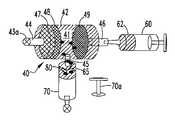
- FIG. 1is an illustration of a tissue harvesting assembly shown in use.
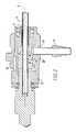
- FIG. 2is a cross-sectional view of the surgical blade hub of the assembly of FIG. 1 .
- FIG. 3is a perspective view of a tissue collection apparatus of the assembly of FIG. 1 .
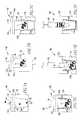
- FIGS. 4 a -4 dschematically illustrate use of the tissue collection apparatus of FIG. 3 to isolate tissue particles of a desired size and to prepare a mixture of tissue-containing gel for tissue repair.
- FIG. 5is an illustration of an alternative tissue harvesting assembly shown in use.
- FIG. 6is a cross-sectional view of a tissue collection apparatus of the assembly of FIG. 5 .
- FIGS. 7 a -7 fschematically illustrate use of the tissue collection apparatus of FIG. 6 to isolate tissue particles of a desired size and to prepare a mixture of tissue-containing gel for tissue repair.
- FIG. 8is an illustration of an alternative implementation of the tissue collection apparatus of the assembly of FIG. 1 .
- FIG. 9is a cross-section view of the tissue collection apparatus of FIG. 8 .
- a tissue harvesting assembly 100comprises a surgical blade 10 used to cut or resect bodily tissue T, such as synovial or adipose tissue, from a donor site, coupled to a tissue collection device 40 for isolating cut tissue of a desired size aspirated through the surgical blade 10 .
- tissue collection device 40for isolating cut tissue of a desired size aspirated through the surgical blade 10 .
- the isolated cut tissueis loaded into, or mixed with, an appropriate carrier, such as a biocompatible gel, and introduced at a tissue repair site.
- the donor site and the repair siteare within the same joint to minimize trauma to the patient and provide for a more expedient surgical procedure.
- Surgical blade 10uses a tube-in-tube construction to shear tissue disposed between cutting edges of an elongate outer non-rotating tubular member 12 and an elongate inner rotating tubular member 14 , as more fully explained in U.S. Pat. No. 5,871,493, which is incorporated herein by reference in its entirety.
- the surgical blade 10comprises a handpiece 20 coupled to the tubular members 12 , 14 via a hub 22 .
- the outer tubular member 12has a proximal end 12 a fixed to the hub 22 and a distal end 12 b defining an opening 15 forming a cutting port or window.
- the inner tubular member 14is rotatably received in the outer tubular member 12 and has a distal end 14 a with a cutting edge (not shown).
- the inner tubular member 14defines an aspiration lumen 16 ( FIG. 2 ) communicating with the cutting edge to remove cut tissue and fluid from a surgical site.
- the cutting edge of the inner tubular member 14is positioned adjacent the opening 15 of the outer tubular member 12 .
- the hub 22 ( FIG. 1 ) of the surgical blade 10is coupled to the outer tubular member 12 via an opening 41 formed in the hub 22 .
- the inner tubular member 14is rotatably received within the outer tubular member 12 and defines the aspiration lumen 16 extending longitudinally through the inner tubular member 14 .
- the inner tubular member 14further defines one or more openings 45 formed through a side wall 14 b of the member 14 within the hub region of the blade 10 , which are in fluid communication with the aspiration lumen 16 and a chamber 26 defined within hub 22 .
- Hub 22further comprises a side port 24 formed through a side wall 28 of hub 22 and in fluid communication with the chamber 26 .
- the side port 24extends in a direction substantially transverse to the longitudinal axis L of the inner tubular member 14 . Coupled to the side port 24 is a tubing connector 29 . The side port 24 provides a pathway for fluid and cut tissue to flow from the surgical blade 10 to the tissue collection device 40 .
- the tissue harvesting assembly 100comprises an introducer 60 ( FIGS. 4B-4D ) and a mixer 65 ( FIGS. 4B-4D ).
- the tissue collection device 40is coupled to the blade 10 via a flexible tubing 50 .
- the tissue collection device 40comprises a substantially cylindrical housing 42 having an inlet 44 and an outlet 46 .
- the inlet 44couples the tubing 50 to the tissue collection device 40 .
- the outlet 46is provided to couple the tissue collection device 40 to a source of vacuum 90 ( FIG. 1 ), such as a vacuum pump or other suitable apparatus for providing aspiration during the surgical procedure, via a tubing 52 .
- a collection apparatus(not shown) can be coupled to the tissue collection device 40 via the tubing 52 to collect tissue and fluid that passes through the tissue collection device 40 .
- Filtration devicessuch as disc filters 47 , 48 , and 49 , are positioned within the housing 42 with filter 47 disposed closest to or adjacent the inlet 44 , filter 49 disposed closest to or adjacent the outlet 46 , and filter 48 disposed between filters 47 and 49 .
- the filters 47 , 48 , and 49 and the housing 42cooperate to define an interior space 41 within the housing 42 .
- the housing 42comprises a port 45 disposed therein, which is in fluid-flow communication with the interior space 41 of the housing 42 .
- the filter 47comprises a set of pores having a pore size of about 0.6 mm to about 2.4 mm
- the filter 48comprises a set of pores having a pore size of about 0.6 mm to about 1 mm
- the filter 49comprises a set of pores having a pore size of about 0.5 mm to about 50 ⁇ m.
- the filters 47 and 48filter out larger tissue particles and allow smaller particles to pass through.
- the filter 49then filters out particles 71 ( FIG. 4B ) of a desired size and allow particles smaller than the desired size to pass through. While two filters 47 , 48 are shown in this implementation, the tissue collection device 40 may comprise only one of the filters 47 , 48 used in conjunction with the filter 49 to collect tissue particles 71 of a desired size.
- the introducer 60( FIGS. 4B-4D ), for example, a syringe, contains a suitable volume (e.g., about 1 ml) of a biocompatible gel 62 . After particle collection, the syringe 60 is used to inject the biocompatible gel 62 into the housing 42 to allow the recovery of the tissue particles 71 collected by the filter 49 as will be discussed in more detail below.
- the mixer 65( FIGS. 4B-4D ), such as a static mixer, is releasably coupled to the port 45 to receive the gel 62 and isolated tissue particles 71 from the interior space 41 of the housing and to create a mixture 80 of gel 62 and tissue particles 71 .
- a receiver 70( FIGS. 4B-4D ) is releasably coupled to the mixer 65 to receive the mixture 80 from the mixer 65 and to, for example, provide the mixture 80 to a surgical site.
- the surgical blade 10is brought into contact with a desired bodily tissue, such as synovial or adipose tissue ( FIG. 1 ).
- a desired bodily tissuesuch as synovial or adipose tissue ( FIG. 1 ).
- the operatorcuts a desired amount of tissue from the donor site using the blade 10 .
- the vacuum source 90aspirates fluid and the cut tissue through the aspiration lumen 16 of the inner tubular member 14 to the tissue collection device 40 .
- the port 45 in the housing 42is closed ( FIG. 4A ), using, for example, a valve, stop, plug, or other suitable device 43 .
- the filter 47removes undesirable cut tissue from the fluid pathway, such as particles larger than, for example, about 0.6 mm to about 2.4 mm.
- the filter 48After passing through the filter 47 , the remainder of the fluid and cut tissue pass through the filter 48 , which removes undesirable cut tissue from the fluid pathway, such as particles larger than, for example, about 0.6 mm to about 1 mm.
- the remainder of the fluid and cut tissuepass through the filter 49 where tissue particles 71 of a desired size, such as particles larger than, for example, about 0.5 mm to about 50 ⁇ m are isolated and/or retained on the filter 49 .
- the remainder of the cut tissue and fluid volumepass through the tissue collection device 40 and are aspirated to the collection apparatus (not shown).
- the inlet 44 of the housing 42is closed off using, for example, a valve, stop, plug, or other suitable device 43 a , the housing 40 is removed from the tubing 50 , 52 , and the receiver 70 and static mixer 65 are attached to the port 45 , using, for example, a Luer Lock (not shown) or other suitable connector ( FIG. 4B ).
- the syringe 60 containing the gel 62is coupled to the outlet 46 , for example, by a Luer lock (not shown) or other suitable connection.
- the gel 62is then injected into the housing 40 and through the filter 49 to mix with and expel the tissue particles 71 from the filter 49 ( FIG. 4C ).
- the expelled tissue particles 71 and the gel 62pass through the interior space 41 of the housing 42 and are forced through the port 45 to the mixer 65 ( FIG. 4C ).
- the mixer 65mixes the tissue particles 71 and the gel 62 to promote even distribution of the tissue particles 71 within the gel 62 , creating a mixture 80 , which flows into the syringe 70 ( FIGS. 4C-4D ).
- the operatorremoves the syringe 70 from the mixer 65 and attaches the plunger 70 a of the syringe 70 ( FIGS. 4 c - d ).
- the operatorthen applies the mixture 80 at a desired location, such as the surgical site shown in FIG. 1 , or the mixture 80 can be placed onto a tissue scaffold or used for further processing.
- FIGS. 5, 6, and 7A-7FAn alternative implementation of a tissue harvesting assembly 200 is illustrated in FIGS. 5, 6, and 7A-7F .
- the tissue harvesting assembly 200comprises a tissue collection device 140 and an introducer 160 ( FIGS. 7E-7F ), for example, a syringe, containing a suitable volume (e.g., about 1 ml) of gel 62 .
- the tissue collection device 140comprises a substantially cylindrical housing 142 having an inlet 44 and an outlet 46 .
- the housing 142comprises a lid 143 that is releasably coupled to the housing 142 using, for example mating threads (not shown), a friction fit, or other suitable connection.
- Filtration devicessuch as disc filters 147 , 148 and a filter 149 having a substantially frusto-conical or basket configuration, are positioned within the housing 142 , with filter 147 disposed closest to or adjacent the inlet 44 , filter 149 disposed closest to or adjacent the outlet 46 , and filter 148 disposed between filters 147 and 149 .
- the filters 147 , 148are disposed within the lid 143 , and the filter 149 is removably attached to an underside 143 a of the lid 143 , using, for example, threads (not shown), a friction fit, or other suitable connection.
- the housing 140comprises one or more projecting ribs 145 ( FIG. 6 ) disposed about the interior of the cylindrical housing 140 .
- the ribs 145are configured and shaped to receive the filter 149 and to releasably hold the filter 149 , for example, by a friction fit, within the housing 140 .
- the filter 147comprises a set of pores having a pore size of about 0.6 mm to about 2.4 mm, the filter 148 comprises a set of pores having a pore size of about 0.6 mm to about 1 mm, and the filter 149 comprises a set of pores having a pore size of about 0.5 mm to about 50 ⁇ m.
- the filters 147 and 148filter out larger tissue particles and allow smaller particles to pass through.
- the filter 149then filters out particles 71 ( FIG. 7B ) of a desired size and allow particles smaller than the desired size to pass through. While two filters 147 , 148 are shown, the tissue collection device 140 may comprise only one of the filters 147 , 148 used in conjunction with the filter 149 to collect tissue particles 71 of a desired size.
- the assembly 200further comprises a container 170 defining a cavity 170 a ( FIGS. 7C-7F ) configured and shaped to receive the filter 149 in a fluid-tight manner therein.
- An upper portion 170 b of the container 170is configured with threads, or other suitable mating connections, to receive the lid 143 of the housing 140 as will be described in more detail below.
- the introducer 160( FIGS. 7E-7F ), for example, a syringe, contains a suitable volume (e.g., about 1 ml) of gel 62 .
- the syringe 160is used to mix the gel 62 with the tissue particles 71 to create a mixture 80 within the container 170 , and thereafter, to aspirate the mixture 80 from the container 170 .
- the surgical blade 10is brought into contact with a desired bodily tissue, such as synovial or adipose tissue ( FIG. 5 ).
- a desired bodily tissuesuch as synovial or adipose tissue ( FIG. 5 ).
- the operatorcuts a desired amount of tissue from the donor site using the blade 10 .
- the vacuum source 90aspirates fluid and the cut tissue through the aspiration lumen 16 of the inner tubular member 14 to the tissue collection device 140 .
- the fluid and cut tissueflow through the filter 147 , which removes undesirable cut tissue from the fluid pathway, such as particles larger than, for example, about 0.6 mm to about 2.4 mm.
- the filter 148After passing through the filter 147 , the remainder of the fluid and cut tissue pass through the filter 148 , which removes undesirable cut tissue from the fluid pathway, such as particles larger than, for example, about 0.6 mm to about 1 mm.
- the remainder of the fluid and cut tissuepass through the filter 149 where tissue particles 71 ( FIG. 7B ) of a desired size, such as particles larger than, for example, about 0.5 mm to about 50 ⁇ m are isolated and/or retained on the filter 149 .
- tissue particles 71FIG. 7B
- tissue particles 71FIG. 7B
- the remainder of the cut tissue and fluid volumepass through the tissue collection device 140 and are aspirated to the collection apparatus (not shown).
- the lid 143is removed from the housing 142 ( FIG. 7B ) and coupled to the upper portion 170 b of the container 170 ( FIG. 7C-7D ).
- the cavity 170 areceives the filter 149 in a fluid-tight manner, via, for example, a friction fit, between the filter 149 and the cavity 170 a .
- the two sets of threaded connectionsmay be configured such that when the lid 143 is unscrewed from the container 170 , the filter 149 is unscrewed from the lid 143 .
- the cavity 170 a of the container 170is configured to provide a sufficient force to retain the filter 149 upon removal of the lid 143 from the container.
- the operatoruses the syringe 160 to inject the gel 62 within the cavity 170 a .
- the gel 62mixes with the tissue particles 71 to form a mixture 80 of tissue and gel ( FIG. 7E ).
- the mixture 80is then aspirated from the container 170 using the syringe 160 ( FIG. 7F ).
- the operatormay apply the mixture 80 at a desired location, such as the surgical site shown in FIG. 5 , or the mixture 80 can be placed onto a tissue scaffold or used as a feed for further processing.
- a tissue collection device 240comprises a housing 242 having an inlet 244 and an outlet 246 . Positioned within the housing 242 are filters 247 and 249 . Filter 247 is disposed adjacent the inlet 244 and filter 249 is disposed adjacent the outlet 246 . Extending between the inlet 244 and the outlet 246 is a fluid-flow conduit 250 in fluid-flow communication with the inlet 244 , the outlet 246 and the filters 247 and 249 .
- the housing 242further comprises ports 252 and 254 in fluid-flow communication with the conduit 250 via conduits 252 a and 254 a , respectively.
- conduits 250 and 252 a and conduits 250 and 254 aare three-way valves 256 , 258 , respectively, that control flow of fluid and tissue or cells between the inlet 244 and the outlet 246 , and flow of gel and a mixture of gel and tissue or cells between the ports 252 and 254 , as will be described in more detail below.
- the filter 247comprises a set of pores having a pore size in the range of about 0.6 mm to about 2.4 mm to allow particles smaller than the pore sizes to pass through the filter 247 and the filter 249 comprises a set of pores having a pore size of about 50 ⁇ m to about 0.5 mm to capture particles larger than about 50 ⁇ m in the filter 249 .
- the operatorcuts a desired amount of tissue from a donor site using the surgical blade 10 , as described above, and fluid and cut tissue are aspirated through the tissue collection device 240 via the inlet 244 .
- the ports 252 and 254are closed to fluid flow by the three-way valves 256 and 258 .
- the filter 247removes undesirable cut tissue from the fluid pathway, such as particles in the range of larger than about 0.6 mm to about 2.4 mm.
- the fluid and cut tissuepass through the conduit 250 and through the filter 249 where tissue particles of a desired size, such as particles larger than, for example, about 0.5 mm to about 50 ⁇ m are isolated and/or retained on the filter 249 .
- tissue particles of a desired sizesuch as particles larger than, for example, about 0.5 mm to about 50 ⁇ m are isolated and/or retained on the filter 249 .
- the remainder of the cut tissue and fluid volumepass through the tissue collection device 240 and are aspirated to a collection apparatus (not shown).
- the inlet 244 of the housing 242is closed off to fluid flow and the port 252 is opened to fluid flow using, for example, three-way valve 256 .
- the outlet 246 of the housing 242is closed off to fluid flow and the port 254 is opened to fluid flow using, for example, three-way valve 258 .
- the receiver 70and optionally, the static mixer 65 , discussed above, can then be attached to the port 252 .
- the syringe 60 containing the gel 62is then coupled to the port 254 and the gel 62 is injected into the housing 240 and through the filter 249 to mix with and expel the tissue particles (not shown) from the filter 249 .
- the expelled tissue particles and gel 62pass through the conduit 250 and are forced through the port 252 to, for example, the mixer 65 ( FIG. 4C ) and into the receiver 70 as described above.
- each of the tissue collection devices 40 , 140 , and 240can be loaded with biological components by other methods.
- cell pellets cultured in vitrocan be aspirated (e.g. using a vacuum source) through one of the tissue collection devices 40 , 140 , 240 and then mixed with a biocompatible gel in the manner described above.
- tissue collection devices 40 , 140 , 240have been described as coupled to the blade 10 via a flexible tubing 50 , the devices 40 , 140 , 240 could be directly coupled to, for example, the port 24 of the blade 10 (see FIGS. 1 and 5 ).
- tissue collection devices 40 , 140 , 240have been described as including substantially cylindrical housings 42 , 142 , and 242 , respectively, housings 42 , 142 , and 242 could be any suitable shape.
- the syringes 60 , 160have been described as containing a volume of about 1 ml of a biocompatible gel 62 , the syringes 60 , 160 could contain more or less of the gel 62 depending on the size of the defect to be treated.
- the mixture 80 of gel 62 and tissue particles 71may be realized solely within the interior space 41 of the housing 42 , and the syringe 70 can be directly coupled to the port 45 to recover the mixture 80 directly from the interior space 41 of the housing 42 .
- the outlet 46 of the tissue collection device 140can be plugged or otherwise sealed and the mixture 80 of gel 62 and tissue particles 71 can be realized directly in the tissue collective device 140 .
- filtration deviceshave been described as either disk-shaped or basket-shaped filters, other suitable filtration devices having any number of possible geometric shapes may be employed. Such examples comprise nucleated cell, microfiltration, tubular, or hollow fiber filtration devices, having, for example, square, cylindrical, tubular, or round geometries.
- any filtration surface that contacts any of the relevant compositions of the tissue, fluid, or other surgical materialsis sterile or can be readily sterilized.
- the injectable gel 62may comprise any suitable biological or synthetic gels.
- the gelcan comprise hyaluronic acid, alginate, cross-linked alginate, collagen, fibrin glue, fibrin clot, poly(N-isopropulacrylamide), agarose, chitin, chitosan, cellulose, polysaccharides, poly(oxyalkylene), a copolymer of poly(ethylene oxide)-poly(propylene oxide), poly(vinyl alcohol), polyacrylate, Matrigel, or blends thereof.
- the apparatuses and systems described hereinmay be considered disposable, although they may be reused upon sterilization, such as by gamma irradiation, ethylene oxide, formalin, hydrogen peroxide, or sodium hypochlorite.
- the filters and syringes discussed hereinmay be commercially obtained.
- the apparatus and componentsmay be plastic, metal, or other suitable material.
- tubing connector 29( FIG. 2 ) being in communication with the aspiration lumen 16 of the inner tubular member 14 via the chamber 26
- the tubing connector 29could be directly coupled to the inner tubular member 14 .
- the tubing connector 29can be coupled to the side port 24 using any suitable form of connection, including glue, weld, press fit, or, alternatively, the tubing connector 29 can be formed as one piece with the hub 22 .
- the tubing connectors described hereincan be made from plastic, metal, or any other suitable materials.
- tissue harvesting assemblyhas been described as including a surgical blade 10 used to cut or resect bodily tissue, such as soft tissue
- tissue harvesting assemblycan comprise an apparatus containing a curet or burr, for example, to remove bodily tissue, such as bone tissue.
Landscapes
- Health & Medical Sciences (AREA)
- Life Sciences & Earth Sciences (AREA)
- Engineering & Computer Science (AREA)
- Biomedical Technology (AREA)
- Surgery (AREA)
- Heart & Thoracic Surgery (AREA)
- General Health & Medical Sciences (AREA)
- Animal Behavior & Ethology (AREA)
- Public Health (AREA)
- Veterinary Medicine (AREA)
- Nuclear Medicine, Radiotherapy & Molecular Imaging (AREA)
- Medical Informatics (AREA)
- Molecular Biology (AREA)
- Orthopedic Medicine & Surgery (AREA)
- Zoology (AREA)
- Organic Chemistry (AREA)
- Biotechnology (AREA)
- Bioinformatics & Cheminformatics (AREA)
- Genetics & Genomics (AREA)
- Wood Science & Technology (AREA)
- Chemical & Material Sciences (AREA)
- Hematology (AREA)
- Anesthesiology (AREA)
- Vascular Medicine (AREA)
- Oral & Maxillofacial Surgery (AREA)
- Dentistry (AREA)
- Transplantation (AREA)
- Cell Biology (AREA)
- General Engineering & Computer Science (AREA)
- Biochemistry (AREA)
- Microbiology (AREA)
- Rheumatology (AREA)
- Materials For Medical Uses (AREA)
- Surgical Instruments (AREA)
Abstract
Description
Claims (12)
Priority Applications (2)
| Application Number | Priority Date | Filing Date | Title |
|---|---|---|---|
| US14/313,847US9822341B2 (en) | 2007-03-30 | 2014-06-24 | Tissue harvesting |
| US15/786,068US20180037866A1 (en) | 2007-03-30 | 2017-10-17 | Method of Tissue Harvesting |
Applications Claiming Priority (8)
| Application Number | Priority Date | Filing Date | Title |
|---|---|---|---|
| US90925307P | 2007-03-30 | 2007-03-30 | |
| GB0715429AGB0715429D0 (en) | 2007-08-08 | 2007-08-08 | Fat pad fragments |
| GB0715429.7 | 2007-08-08 | ||
| US99221007P | 2007-12-04 | 2007-12-04 | |
| US666208P | 2008-01-25 | 2008-01-25 | |
| US666308P | 2008-01-25 | 2008-01-25 | |
| US12/058,910US8795194B2 (en) | 2007-03-30 | 2008-03-31 | Tissue harvesting |
| US14/313,847US9822341B2 (en) | 2007-03-30 | 2014-06-24 | Tissue harvesting |
Related Parent Applications (1)
| Application Number | Title | Priority Date | Filing Date |
|---|---|---|---|
| US12/058,910DivisionUS8795194B2 (en) | 2007-03-30 | 2008-03-31 | Tissue harvesting |
Related Child Applications (1)
| Application Number | Title | Priority Date | Filing Date |
|---|---|---|---|
| US15/786,068ContinuationUS20180037866A1 (en) | 2007-03-30 | 2017-10-17 | Method of Tissue Harvesting |
Publications (2)
| Publication Number | Publication Date |
|---|---|
| US20140308742A1 US20140308742A1 (en) | 2014-10-16 |
| US9822341B2true US9822341B2 (en) | 2017-11-21 |
Family
ID=39795599
Family Applications (8)
| Application Number | Title | Priority Date | Filing Date |
|---|---|---|---|
| US12/058,910Active2030-09-21US8795194B2 (en) | 2007-03-30 | 2008-03-31 | Tissue harvesting |
| US12/059,180Active2031-01-25US8696674B2 (en) | 2007-03-30 | 2008-03-31 | Tissue harvesting |
| US14/192,306AbandonedUS20140249513A1 (en) | 2007-03-30 | 2014-02-27 | Tissue harvesting |
| US14/192,231ActiveUS9909103B2 (en) | 2007-03-30 | 2014-02-27 | Tissue harvesting |
| US14/313,827ActiveUS9777257B2 (en) | 2007-03-30 | 2014-06-24 | Tissue harvesting |
| US14/313,847ActiveUS9822341B2 (en) | 2007-03-30 | 2014-06-24 | Tissue harvesting |
| US14/313,775AbandonedUS20140309651A1 (en) | 2007-03-30 | 2014-06-24 | Tissue Harvesting |
| US15/786,068AbandonedUS20180037866A1 (en) | 2007-03-30 | 2017-10-17 | Method of Tissue Harvesting |
Family Applications Before (5)
| Application Number | Title | Priority Date | Filing Date |
|---|---|---|---|
| US12/058,910Active2030-09-21US8795194B2 (en) | 2007-03-30 | 2008-03-31 | Tissue harvesting |
| US12/059,180Active2031-01-25US8696674B2 (en) | 2007-03-30 | 2008-03-31 | Tissue harvesting |
| US14/192,306AbandonedUS20140249513A1 (en) | 2007-03-30 | 2014-02-27 | Tissue harvesting |
| US14/192,231ActiveUS9909103B2 (en) | 2007-03-30 | 2014-02-27 | Tissue harvesting |
| US14/313,827ActiveUS9777257B2 (en) | 2007-03-30 | 2014-06-24 | Tissue harvesting |
Family Applications After (2)
| Application Number | Title | Priority Date | Filing Date |
|---|---|---|---|
| US14/313,775AbandonedUS20140309651A1 (en) | 2007-03-30 | 2014-06-24 | Tissue Harvesting |
| US15/786,068AbandonedUS20180037866A1 (en) | 2007-03-30 | 2017-10-17 | Method of Tissue Harvesting |
Country Status (5)
| Country | Link |
|---|---|
| US (8) | US8795194B2 (en) |
| EP (2) | EP2139400B1 (en) |
| AT (1) | ATE515979T1 (en) |
| AU (2) | AU2008232516B2 (en) |
| WO (2) | WO2008121920A1 (en) |
Cited By (2)
| Publication number | Priority date | Publication date | Assignee | Title |
|---|---|---|---|---|
| US20160333305A1 (en)* | 2015-05-15 | 2016-11-17 | Black Tie Medical Inc. | Device and Method for Breaking Down and Sizing Harvested Fat |
| US12128334B2 (en)* | 2018-09-05 | 2024-10-29 | Kin Mun Chin | Filter press with threadably advanced filtrate receiving plunger |
Families Citing this family (75)
| Publication number | Priority date | Publication date | Assignee | Title |
|---|---|---|---|---|
| US9232959B2 (en) | 2007-01-02 | 2016-01-12 | Aquabeam, Llc | Multi fluid tissue resection methods and devices |
| US12290277B2 (en) | 2007-01-02 | 2025-05-06 | Aquabeam, Llc | Tissue resection with pressure sensing |
| US8795194B2 (en) | 2007-03-30 | 2014-08-05 | Smith & Nephew, Inc. | Tissue harvesting |
| ES2769535T3 (en) | 2008-03-06 | 2020-06-26 | Aquabeam Llc | Tissue ablation and cauterization with optical energy carried in a fluid stream |
| US8801725B2 (en) | 2008-03-10 | 2014-08-12 | Zimmer Orthobiologics, Inc. | Instruments and methods used when repairing a defect on a tissue surface |
| US8100874B1 (en) | 2009-05-22 | 2012-01-24 | Donnell Mark Jordan | Tissue refining device |
| US9867788B2 (en)* | 2009-07-09 | 2018-01-16 | Boston Scientific Scimed, Inc. | Multi-chamber cellular mixing and delivery system and method |
| US10588609B2 (en) | 2010-02-04 | 2020-03-17 | Procept Biorobotics Corporation | Gene analysis and generation of stem cell methods and apparatus |
| US8790321B2 (en) | 2010-04-21 | 2014-07-29 | Genesis Medical Devices, LLC | Apparatus, system, and method for harvesting improved bone graft material with reamer-irrigator-aspirator (RIA) device |
| US8858546B2 (en)* | 2010-05-12 | 2014-10-14 | Ethicon Endo-Surgery, Inc. | Instrument for debriding fistula and applying therapeutic cells |
| US8986331B2 (en) | 2010-05-12 | 2015-03-24 | Ethicon Endo-Surgery, Inc. | Instrument for debriding fistula and applying therapeutic cells |
| EP2389881B1 (en)* | 2010-05-26 | 2013-12-11 | Human Med AG | Device for separating and draining tissue cells from a biological structure using a liquid jet |
| US20110295238A1 (en)* | 2010-05-26 | 2011-12-01 | Human Med Ag | Device for fluid jet-supported separation and suctioning of tissue cells from a biological structure |
| US9113916B2 (en) | 2010-08-31 | 2015-08-25 | Zimmer, Inc. | Drill bit for osteochondral drilling with guiding element and uses thereof |
| US8435305B2 (en) | 2010-08-31 | 2013-05-07 | Zimmer, Inc. | Osteochondral graft delivery device and uses thereof |
| WO2012047286A1 (en)* | 2010-10-04 | 2012-04-12 | Spinesmith Partners L.P. | Device and method for delivering mechanically released cells from liposuction aspirates |
| WO2012148502A2 (en)* | 2011-04-28 | 2012-11-01 | Spinesmith Partners Lp | Lipoaspirate stem cell separation system and methods thereof |
| US9480464B2 (en) | 2011-07-29 | 2016-11-01 | New York University | Tissue collection system |
| US9186166B2 (en)* | 2011-09-01 | 2015-11-17 | Depuy Mitek, Llc | Tissue shavers |
| HK1197964A2 (en) | 2011-12-03 | 2015-02-27 | DePuy Synthes Products, Inc. | Safe cutting heads and systems for fast removal of a target tissue |
| EP3351196A1 (en) | 2012-02-29 | 2018-07-25 | Procept Biorobotics Corporation | Automated image-guided tissue resection and treatment |
| IN2014KN02620A (en)* | 2012-04-30 | 2015-05-08 | Univ Johns Hopkins | |
| US9307961B2 (en)* | 2012-06-29 | 2016-04-12 | Carefusion 2200, Inc. | Fine needle aspiration biopsy device |
| EP4039236A1 (en) | 2013-02-20 | 2022-08-10 | Cytrellis Biosystems, Inc. | System for tightening a region of skin |
| US9867939B2 (en) | 2013-03-12 | 2018-01-16 | Allergan, Inc. | Adipose tissue combinations, devices, and uses thereof |
| US20140350516A1 (en) | 2013-05-23 | 2014-11-27 | Allergan, Inc. | Mechanical syringe accessory |
| EP3021768B1 (en)* | 2013-07-19 | 2020-08-19 | DePuy Synthes Products, Inc. | An anti-clogging device for a vacuum-assisted, tissue removal system |
| AU2014306273B2 (en) | 2013-08-09 | 2019-07-11 | Cytrellis Biosystems, Inc. | Methods and apparatuses for skin treatment using non-thermal tissue ablation |
| BR112016005036A2 (en) | 2013-09-06 | 2020-04-07 | Procept Biorobotics Corp | automated image guided tissue resection device |
| US9248384B2 (en) | 2013-10-02 | 2016-02-02 | Allergan, Inc. | Fat processing system |
| US9782193B2 (en) | 2013-12-11 | 2017-10-10 | Medos International Sàrl | Tissue shaving device having a fluid removal path |
| US11464500B2 (en)* | 2014-03-09 | 2022-10-11 | Spinesmith Holdings, Llc | Combined trocar and cannula bone marrow aspiration device with integral valve and ports for aspiration, and methods for using same |
| US10029048B2 (en) | 2014-05-13 | 2018-07-24 | Allergan, Inc. | High force injection devices |
| US9925068B2 (en) | 2014-05-30 | 2018-03-27 | Treace Medical Concepts, Inc. | Bone harvester and bone marrow removal system and method |
| CN104161562B (en)* | 2014-06-16 | 2017-05-24 | 李万里 | Minimally invasive bone fetcher |
| JP6651471B2 (en) | 2014-06-30 | 2020-02-19 | プロセプト バイオロボティクス コーポレイション | Fluid jet tissue ablation and cold coagulation (AQUABLATION) method and apparatus |
| EP3188667B1 (en) | 2014-09-05 | 2020-12-09 | PROCEPT BioRobotics Corporation | Apparatus for isolation of cells |
| EP4477143A3 (en) | 2014-09-05 | 2025-03-19 | PROCEPT BioRobotics Corporation | Physician controlled tissue resection integrated with treatment mapping of target organ images |
| CA2967636A1 (en) | 2014-11-14 | 2016-05-19 | Cytrellis Biosystems, Inc. | Devices and methods for ablation of the skin |
| EP3268063A4 (en) | 2015-03-10 | 2018-10-31 | Allergan Pharmaceuticals Holdings (Ireland) Unlimited Company | Multiple needle injector |
| US10231743B2 (en)* | 2015-03-24 | 2019-03-19 | Stryker European Holdings I, Llc | Bone marrow harvesting device and storage methods |
| EP3291738B1 (en)* | 2015-05-07 | 2024-02-14 | Avitus Orthopaedics, Inc. | Systems for bone and tissue harvesting |
| CN108348266A (en)* | 2015-11-25 | 2018-07-31 | 史密夫和内修有限公司 | Tissue capture device for cartilage autograft transfer system |
| ES2919935T3 (en)* | 2016-03-15 | 2022-07-29 | Interscope Inc | Surgical console, sample receiver and insertable endoscopic instrument for tissue extraction |
| CN109310827B (en) | 2016-04-08 | 2021-09-07 | 阿勒根公司 | Suction and Injection Devices |
| AU2016418409B2 (en) | 2016-08-12 | 2022-08-11 | Tobra Medical, Inc. | Collection system for surgical use |
| CN109922740B (en) | 2016-09-21 | 2022-08-23 | 希特利斯生物系统有限公司 | Device and method for cosmetic skin reconstruction |
| EP3544518B1 (en) | 2016-11-23 | 2025-10-15 | C. R. Bard, Inc. | Single insertion multiple sample biopsy apparatus |
| WO2018213705A2 (en) | 2017-05-18 | 2018-11-22 | Medline Industries, Inc. | Removable inlet manifold for a medical waste collection system |
| JP6380868B1 (en)* | 2017-06-05 | 2018-08-29 | オーソセル・リミテッド | Medical treatment kit and related methods |
| US11667877B2 (en)* | 2017-08-23 | 2023-06-06 | Imad E. SHEHADI | Tissue processing apparatus, a filter and a method for processing tissue therefrom |
| CN107744404A (en)* | 2017-09-30 | 2018-03-02 | 中国人民解放军第三军医大学第附属医院 | Subpatellar fat pad fragment of tissue collection system and collection method in Arthroscopic Operative |
| EP3716861B1 (en) | 2017-11-30 | 2024-10-23 | C. R. Bard, Inc. | Sample container for a biopsy apparatus |
| US10980549B2 (en)* | 2018-02-14 | 2021-04-20 | DePuy Synthes Products, Inc. | Graft filter with locking graft filter element and graft extractor |
| US11065372B2 (en)* | 2018-03-27 | 2021-07-20 | Gyrus Acmi, Inc. | Needle system restrictor |
| CN108379663B (en)* | 2018-04-24 | 2023-05-26 | 中国人民解放军第四军医大学 | Device and method for trapping and enriching cells in porous regular body scaffold material |
| EP3806756B1 (en)* | 2018-06-13 | 2024-01-03 | Stryker European Operations Limited | Bone fragment collector and processor |
| CA3012795C (en)* | 2018-07-30 | 2020-05-26 | Ruslan MOLCHANOV | Bone dust trap |
| US12042175B2 (en)* | 2019-02-13 | 2024-07-23 | Stryker European Operations Limited | Bone material harvesting device |
| US10471188B1 (en) | 2019-04-12 | 2019-11-12 | Stryker Corporation | Manifold for filtering medical waste being drawn under vacuum into a medical waste collection system |
| US12350418B2 (en) | 2019-04-12 | 2025-07-08 | Stryker Corporation | Manifold for a medical waste collection system |
| US11318242B2 (en) | 2019-04-12 | 2022-05-03 | Stryker Corporation | Manifold for a medical waste collection system |
| USD956967S1 (en) | 2019-11-11 | 2022-07-05 | Stryker Corporation | Manifold housing for a medical waste collection device |
| USD996640S1 (en) | 2019-11-11 | 2023-08-22 | Stryker Corporation | Specimen collection tray |
| USD930850S1 (en) | 2019-11-20 | 2021-09-14 | Stryker Corporation | Specimen collection tray |
| USD919799S1 (en) | 2019-11-11 | 2021-05-18 | Stryker Corporation | Manifold housing for a medical waste collection device |
| USD1031076S1 (en) | 2019-11-20 | 2024-06-11 | Stryker Corporation | Specimen collection tray |
| EP4076290B1 (en) | 2019-12-18 | 2024-07-31 | Stryker European Operations Limited | Bone fragment collector and processor |
| US11786266B2 (en)* | 2020-02-14 | 2023-10-17 | Arthrex, Inc. | Variable particle size tissue collector |
| US20230309971A1 (en)* | 2020-09-04 | 2023-10-05 | Arthrex, Inc. | Systems for capturing cells |
| KR102654900B1 (en)* | 2021-10-20 | 2024-04-26 | 주식회사 로킷헬스케어 | Apparatus for collecting infrapatellar fat pad |
| US12023046B2 (en)* | 2022-03-11 | 2024-07-02 | The Cleveland Clinic Foundation | Bone dust collector device |
| EP4279575A1 (en) | 2022-05-20 | 2023-11-22 | Albert-Ludwigs-Universität Freiburg | Device and method for particle isolation |
| DE102022121041A1 (en)* | 2022-08-19 | 2024-02-22 | H & B Electronic Gmbh & Co. Kg | Collection device |
| AU2022490560A1 (en) | 2022-11-30 | 2025-06-05 | Euromi | Size-classifier of adipocyte cells and liposuction system comprising same |
Citations (79)
| Publication number | Priority date | Publication date | Assignee | Title |
|---|---|---|---|---|
| US3921496A (en) | 1974-11-04 | 1975-11-25 | J Frank Helderman | Fastener assembly |
| DE3417248A1 (en) | 1984-05-10 | 1985-11-14 | Alois 4040 Neuss Ferch | Apparatus for separating out solids from liquids |
| US4605414A (en) | 1984-06-06 | 1986-08-12 | John Czajka | Reconstruction of a cruciate ligament |
| US4790850A (en) | 1986-03-14 | 1988-12-13 | Richards Medical Company | Phosthetic ligament |
| US4964992A (en) | 1989-03-21 | 1990-10-23 | Goldsmith Susan H | Method of making membrane-type filter and product thereof |
| US5071420A (en) | 1991-04-25 | 1991-12-10 | Depuy Du Pont Orthopaedics | Isometry testing device |
| US5077012A (en) | 1989-01-10 | 1991-12-31 | La Mina Ltd. | Device for detecting disease markers |
| US5084050A (en) | 1984-12-14 | 1992-01-28 | Klaus Draenert | Implant for bone reinforcement and for anchoring bone screws, implants and implant parts |
| US5108381A (en) | 1991-03-11 | 1992-04-28 | Kolozsi William Z | Tissue sample collection trap |
| US5139520A (en) | 1990-01-31 | 1992-08-18 | American Cyanamid Company | Method for acl reconstruction |
| US5197976A (en) | 1991-09-16 | 1993-03-30 | Atrium Medical Corporation | Manually separable multi-lumen vascular graft |
| WO1993015694A1 (en) | 1992-02-14 | 1993-08-19 | Board Of Regents, The University Of Texas System | Multi-phase bioerodible implant/carrier and method of manufacturing and using same |
| US5383878A (en) | 1990-09-04 | 1995-01-24 | Hip Developments Pty Ltd. | Surgical screw |
| US5439684A (en) | 1989-09-21 | 1995-08-08 | Osteotech, Inc. | Shaped, swollen demineralized bone and its use in bone repair |
| EP0669105A2 (en) | 1994-02-23 | 1995-08-30 | SMITH & NEPHEW DYONICS INC | Endoscopic resection instrument |
| US5456721A (en) | 1991-07-11 | 1995-10-10 | Legrand; Jean-Jacques | Device for reinforcing a ligament transplant during reconstructive surgery |
| US5456274A (en) | 1993-10-28 | 1995-10-10 | Selbee; Kathie | Hair band with removable cover |
| US5490750A (en) | 1994-06-09 | 1996-02-13 | Gundy; William P. | Anchoring device for a threaded member |
| US5626751A (en) | 1992-07-15 | 1997-05-06 | Daiichi Pharmaceutical Co., Ltd. | Filter unit and high-pressure sizing apparatus |
| US5632748A (en) | 1993-06-14 | 1997-05-27 | Linvatec Corporation | Endosteal anchoring device for urging a ligament against a bone surface |
| US5641256A (en) | 1994-06-09 | 1997-06-24 | Npc, Inc. | Anchoring device for a threaded member |
| US5671695A (en) | 1994-07-28 | 1997-09-30 | Depuy Inc. | Replacement ligament graft passer and method |
| US5683419A (en) | 1995-06-06 | 1997-11-04 | Thal; Raymond | Knotless suture anchor assembly |
| US5713904A (en) | 1997-02-12 | 1998-02-03 | Third Millennium Engineering, Llc | Selectively expandable sacral fixation screw-sleeve device |
| US5716359A (en) | 1995-05-30 | 1998-02-10 | Asahi Kogaku Kogyo Kabushiki Kaisha | Anchor and method for fixing a screw in bone |
| US5766134A (en) | 1995-07-18 | 1998-06-16 | Atrion Medical Products, Inc. | Autogenous bone specimen collector |
| US5769894A (en) | 1997-02-05 | 1998-06-23 | Smith & Nephew, Inc. | Graft attachment device and method of attachment |
| US5770073A (en) | 1996-03-15 | 1998-06-23 | Minntech Corporation | Combined cardiotomy and venous reservoir |
| US5804366A (en)* | 1995-02-09 | 1998-09-08 | Baxter International Inc. | Method and apparatus for sodding microvessel cells onto a synthetic vascular graft |
| US5817032A (en) | 1996-05-14 | 1998-10-06 | Biopath Automation Llc. | Means and method for harvesting and handling tissue samples for biopsy analysis |
| US5827217A (en)* | 1996-09-04 | 1998-10-27 | Silver; Frederick H. | Process and apparatus for harvesting tissue for processing tissue and process and apparatus for re-injecting processed tissue |
| US5876452A (en) | 1992-02-14 | 1999-03-02 | Board Of Regents, University Of Texas System | Biodegradable implant |
| US5899938A (en) | 1996-11-27 | 1999-05-04 | Joseph H. Sklar | Graft ligament anchor and method for attaching a graft ligament to a bone |
| US5935129A (en) | 1997-03-07 | 1999-08-10 | Innovasive Devices, Inc. | Methods and apparatus for anchoring objects to bone |
| US5964764A (en) | 1998-03-24 | 1999-10-12 | Hugh S. West, Jr. | Apparatus and methods for mounting a ligament graft to a bone |
| US5984926A (en) | 1998-02-24 | 1999-11-16 | Jones; A. Alexander M. | Bone screw shimming and bone graft containment system and method |
| WO1999059500A2 (en) | 1996-07-03 | 1999-11-25 | The Cleveland Clinic Foundation | Apparatus and methods for preparing an implantable graft |
| US6013853A (en) | 1992-02-14 | 2000-01-11 | The University Of Texas System | Continuous release polymeric implant carrier |
| US6071284A (en) | 1995-10-30 | 2000-06-06 | Biomedical Enterprises, Inc. | Materials collection system and uses thereof |
| US6203572B1 (en) | 1999-02-09 | 2001-03-20 | Linvatec Corporation | Device and method for ligament reconstruction |
| US6299763B1 (en) | 1999-04-09 | 2001-10-09 | Arthur Ashman | Autogenous bone and cell filter trap |
| US20020055749A1 (en) | 1997-02-25 | 2002-05-09 | Philip Stuart Esnouf | Surgical aid for connective tissue grafting and method for employing same |
| US6409750B1 (en) | 1999-02-01 | 2002-06-25 | Board Of Regents, The University Of Texas System | Woven bifurcated and trifurcated stents and methods for making the same |
| US20020108622A1 (en) | 1997-02-12 | 2002-08-15 | Whelan Jeffery M. | Method of loading tendons into the knee |
| US6454808B1 (en) | 1998-01-28 | 2002-09-24 | M-E-System Inc. | Finger joint prosthesis |
| US20020161449A1 (en) | 2001-02-28 | 2002-10-31 | Muschler George F. | Composite bone marrow graft material with method and kit |
| US20030036801A1 (en) | 2001-07-16 | 2003-02-20 | Schwartz Herbert E. | Cartilage repair apparatus and method |
| US6533816B2 (en) | 1999-02-09 | 2003-03-18 | Joseph H. Sklar | Graft ligament anchor and method for attaching a graft ligament to a bone |
| US20030093034A1 (en) | 2001-11-09 | 2003-05-15 | King-Ming Chang | Method and apparatus for preparing and culturing cells |
| US20030114936A1 (en) | 1998-10-12 | 2003-06-19 | Therics, Inc. | Complex three-dimensional composite scaffold resistant to delimination |
| US20030130594A1 (en) | 2002-01-02 | 2003-07-10 | Hynes Richard A. | Autogenous bone collection and delivery system |
| WO2003073945A1 (en) | 2002-03-07 | 2003-09-12 | Sandor George K B | Bone chip harvesting trap |
| WO2003101306A1 (en) | 2002-05-31 | 2003-12-11 | Vidacare Corporation | Apparatus and method to access the bone marrow |
| EP1378209A1 (en) | 2001-03-06 | 2004-01-07 | Atsushi Takahashi | Self-bone collecting and mixingly agitating device |
| US20040078090A1 (en) | 2002-10-18 | 2004-04-22 | Francois Binette | Biocompatible scaffolds with tissue fragments |
| US20040097828A1 (en) | 2002-11-18 | 2004-05-20 | Pellegrino Richard C. | Bone marrow aspiration system |
| US6746483B1 (en) | 2000-03-16 | 2004-06-08 | Smith & Nephew, Inc. | Sheaths for implantable fixation devices |
| US20040193071A1 (en) | 2003-03-28 | 2004-09-30 | Ethicon, Inc. | Tissue collection device and methods |
| US6840770B2 (en) | 2001-12-28 | 2005-01-11 | Mcdevitt Dennis | Expandable polymer dental implant and method of use |
| US20050038520A1 (en) | 2003-08-11 | 2005-02-17 | Francois Binette | Method and apparatus for resurfacing an articular surface |
| US20050049521A1 (en) | 2000-11-06 | 2005-03-03 | Suros Surgical Systems, Inc. | Collection filter for biopsy apparatus |
| US20050059905A1 (en) | 2003-09-11 | 2005-03-17 | Robert Boock | Tissue extraction and maceration device |
| US20050125077A1 (en) | 2003-12-05 | 2005-06-09 | Harmon Alexander M. | Viable tissue repair implants and methods of use |
| WO2005110278A2 (en) | 2003-04-29 | 2005-11-24 | Musculoskeletal Transplant Foundation | Cartilage repair mixture containing allograft chondrocytes |
| US20060121609A1 (en) | 2004-09-21 | 2006-06-08 | Yannas Ioannis V | Gradient scaffolding and methods of producing the same |
| US20060141623A1 (en) | 2002-04-08 | 2006-06-29 | Millenium Biologix, Inc. | Automated tissue engineering system |
| WO2006098293A1 (en) | 2005-03-15 | 2006-09-21 | Atsushi Takahashi | Autologous bone collection device having enhanced suction efficiency |
| US20060213374A1 (en)* | 2005-03-23 | 2006-09-28 | Shippert Ronald D | Tissue transplantation method and apparatus |
| US7115100B2 (en) | 2002-11-15 | 2006-10-03 | Ethicon, Inc. | Tissue biopsy and processing device |
| US20070016100A1 (en) | 2002-05-31 | 2007-01-18 | Miller Larry J | Apparatus and Methods to Harvest Bone and Bone Marrow |
| US7220283B2 (en) | 2005-01-24 | 2007-05-22 | Exactech, Inc. | Prosthesis including a mechanism for attaching a first component to a second component |
| US20070156161A1 (en)* | 2005-12-29 | 2007-07-05 | Weadock Kevin S | Method and device for repositioning tissue |
| US20070185585A1 (en) | 2004-03-09 | 2007-08-09 | Brat Bracy | Implant Scaffold Combined With Autologous Tissue, Allogenic Tissue, Cultured Tissue, or combinations Thereof |
| US7279008B2 (en) | 2000-03-16 | 2007-10-09 | Smith & Nephew, Inc. | Sheaths for implantable fixation devices |
| US20080125863A1 (en) | 2006-11-28 | 2008-05-29 | Mckay William F | Implant designs and methods of improving cartilage repair |
| US20080177200A1 (en) | 2007-01-23 | 2008-07-24 | Jimro Co., Ltd. | Bone marrow harvesting drill |
| US20090202963A1 (en) | 2001-12-28 | 2009-08-13 | Incumed, Inc. | Expandable polymer dental implant and method of use |
| US7637872B1 (en) | 2003-04-07 | 2009-12-29 | William Casey Fox | Bone marrow aspiration and biomaterial mixing system |
| EP2139400A1 (en) | 2007-03-30 | 2010-01-06 | Smith & Nephew, Inc. | Tissue harvesting |
Family Cites Families (6)
| Publication number | Priority date | Publication date | Assignee | Title |
|---|---|---|---|---|
| US3231091A (en)* | 1962-10-29 | 1966-01-25 | Pfaudler Permutit Inc | Separator |
| US6020196A (en)* | 1996-05-09 | 2000-02-01 | Baxter International Inc. | Devices for harvesting and homogenizing adipose tissue containing autologous endothelial cells |
| US7588732B2 (en)* | 2004-03-30 | 2009-09-15 | Genesis Biosystems, Inc. | Autologus tissue harvesting and irrigation device |
| US7713232B2 (en)* | 2005-11-04 | 2010-05-11 | Medrad, Inc. | System for washing and processing of cells for delivery thereof to tissue |
| US20080262616A1 (en)* | 2007-04-18 | 2008-10-23 | Warsaw Orthopedic, Inc. | Osteochondral graft and method of use for repairing an articular cartilage defect site |
| JP2010531142A (en)* | 2007-06-22 | 2010-09-24 | サークル バイオロジクス、 エルエルシー. | Liquid concentrator, autologous concentrated body fluid, and methods of use thereof |
- 2008
- 2008-03-31USUS12/058,910patent/US8795194B2/enactiveActive
- 2008-03-31AUAU2008232516Apatent/AU2008232516B2/ennot_activeCeased
- 2008-03-31EPEP08744717Apatent/EP2139400B1/ennot_activeNot-in-force
- 2008-03-31USUS12/059,180patent/US8696674B2/enactiveActive
- 2008-03-31WOPCT/US2008/058821patent/WO2008121920A1/enactiveApplication Filing
- 2008-04-08EPEP08745282Apatent/EP2142102B1/ennot_activeNot-in-force
- 2008-04-08WOPCT/US2008/059624patent/WO2008122057A1/enactiveApplication Filing
- 2008-04-08ATAT08745282Tpatent/ATE515979T1/ennot_activeIP Right Cessation
- 2008-04-08AUAU2008232461Apatent/AU2008232461B2/ennot_activeCeased
- 2014
- 2014-02-27USUS14/192,306patent/US20140249513A1/ennot_activeAbandoned
- 2014-02-27USUS14/192,231patent/US9909103B2/enactiveActive
- 2014-06-24USUS14/313,827patent/US9777257B2/enactiveActive
- 2014-06-24USUS14/313,847patent/US9822341B2/enactiveActive
- 2014-06-24USUS14/313,775patent/US20140309651A1/ennot_activeAbandoned
- 2017
- 2017-10-17USUS15/786,068patent/US20180037866A1/ennot_activeAbandoned
Patent Citations (87)
| Publication number | Priority date | Publication date | Assignee | Title |
|---|---|---|---|---|
| US3921496A (en) | 1974-11-04 | 1975-11-25 | J Frank Helderman | Fastener assembly |
| DE3417248A1 (en) | 1984-05-10 | 1985-11-14 | Alois 4040 Neuss Ferch | Apparatus for separating out solids from liquids |
| US4605414A (en) | 1984-06-06 | 1986-08-12 | John Czajka | Reconstruction of a cruciate ligament |
| US5084050A (en) | 1984-12-14 | 1992-01-28 | Klaus Draenert | Implant for bone reinforcement and for anchoring bone screws, implants and implant parts |
| US4790850A (en) | 1986-03-14 | 1988-12-13 | Richards Medical Company | Phosthetic ligament |
| US5077012A (en) | 1989-01-10 | 1991-12-31 | La Mina Ltd. | Device for detecting disease markers |
| US4964992A (en) | 1989-03-21 | 1990-10-23 | Goldsmith Susan H | Method of making membrane-type filter and product thereof |
| US5439684A (en) | 1989-09-21 | 1995-08-08 | Osteotech, Inc. | Shaped, swollen demineralized bone and its use in bone repair |
| US5139520A (en) | 1990-01-31 | 1992-08-18 | American Cyanamid Company | Method for acl reconstruction |
| US5383878A (en) | 1990-09-04 | 1995-01-24 | Hip Developments Pty Ltd. | Surgical screw |
| US5108381A (en) | 1991-03-11 | 1992-04-28 | Kolozsi William Z | Tissue sample collection trap |
| US5071420A (en) | 1991-04-25 | 1991-12-10 | Depuy Du Pont Orthopaedics | Isometry testing device |
| US5456721A (en) | 1991-07-11 | 1995-10-10 | Legrand; Jean-Jacques | Device for reinforcing a ligament transplant during reconstructive surgery |
| US5197976A (en) | 1991-09-16 | 1993-03-30 | Atrium Medical Corporation | Manually separable multi-lumen vascular graft |
| US5876452A (en) | 1992-02-14 | 1999-03-02 | Board Of Regents, University Of Texas System | Biodegradable implant |
| US5607474A (en) | 1992-02-14 | 1997-03-04 | Board Of Regents, University Of Texas System | Multi-phase bioerodible implant/carrier and method of manufacturing and using same |
| WO1993015694A1 (en) | 1992-02-14 | 1993-08-19 | Board Of Regents, The University Of Texas System | Multi-phase bioerodible implant/carrier and method of manufacturing and using same |
| US6013853A (en) | 1992-02-14 | 2000-01-11 | The University Of Texas System | Continuous release polymeric implant carrier |
| US5626751A (en) | 1992-07-15 | 1997-05-06 | Daiichi Pharmaceutical Co., Ltd. | Filter unit and high-pressure sizing apparatus |
| US5632748A (en) | 1993-06-14 | 1997-05-27 | Linvatec Corporation | Endosteal anchoring device for urging a ligament against a bone surface |
| US5456274A (en) | 1993-10-28 | 1995-10-10 | Selbee; Kathie | Hair band with removable cover |
| EP0669105A2 (en) | 1994-02-23 | 1995-08-30 | SMITH & NEPHEW DYONICS INC | Endoscopic resection instrument |
| US5490750A (en) | 1994-06-09 | 1996-02-13 | Gundy; William P. | Anchoring device for a threaded member |
| US5641256A (en) | 1994-06-09 | 1997-06-24 | Npc, Inc. | Anchoring device for a threaded member |
| US5671695A (en) | 1994-07-28 | 1997-09-30 | Depuy Inc. | Replacement ligament graft passer and method |
| US5804366A (en)* | 1995-02-09 | 1998-09-08 | Baxter International Inc. | Method and apparatus for sodding microvessel cells onto a synthetic vascular graft |
| US5716359A (en) | 1995-05-30 | 1998-02-10 | Asahi Kogaku Kogyo Kabushiki Kaisha | Anchor and method for fixing a screw in bone |
| US5683419A (en) | 1995-06-06 | 1997-11-04 | Thal; Raymond | Knotless suture anchor assembly |
| US5720765A (en) | 1995-06-06 | 1998-02-24 | Thal; Raymond | Knotless suture anchor assembly |
| US5766134A (en) | 1995-07-18 | 1998-06-16 | Atrion Medical Products, Inc. | Autogenous bone specimen collector |
| US6071284A (en) | 1995-10-30 | 2000-06-06 | Biomedical Enterprises, Inc. | Materials collection system and uses thereof |
| US5770073A (en) | 1996-03-15 | 1998-06-23 | Minntech Corporation | Combined cardiotomy and venous reservoir |
| US5817032A (en) | 1996-05-14 | 1998-10-06 | Biopath Automation Llc. | Means and method for harvesting and handling tissue samples for biopsy analysis |
| WO1999059500A2 (en) | 1996-07-03 | 1999-11-25 | The Cleveland Clinic Foundation | Apparatus and methods for preparing an implantable graft |
| US5827217A (en)* | 1996-09-04 | 1998-10-27 | Silver; Frederick H. | Process and apparatus for harvesting tissue for processing tissue and process and apparatus for re-injecting processed tissue |
| US5899938A (en) | 1996-11-27 | 1999-05-04 | Joseph H. Sklar | Graft ligament anchor and method for attaching a graft ligament to a bone |
| US5769894A (en) | 1997-02-05 | 1998-06-23 | Smith & Nephew, Inc. | Graft attachment device and method of attachment |
| US5713904A (en) | 1997-02-12 | 1998-02-03 | Third Millennium Engineering, Llc | Selectively expandable sacral fixation screw-sleeve device |
| US20020108622A1 (en) | 1997-02-12 | 2002-08-15 | Whelan Jeffery M. | Method of loading tendons into the knee |
| US6602290B2 (en) | 1997-02-25 | 2003-08-05 | Centerpulse Orthopedics Inc. | Surgical aid for connective tissue grafting and method for employing same |
| US20020055749A1 (en) | 1997-02-25 | 2002-05-09 | Philip Stuart Esnouf | Surgical aid for connective tissue grafting and method for employing same |
| US5935129A (en) | 1997-03-07 | 1999-08-10 | Innovasive Devices, Inc. | Methods and apparatus for anchoring objects to bone |
| US6454808B1 (en) | 1998-01-28 | 2002-09-24 | M-E-System Inc. | Finger joint prosthesis |
| US5984926A (en) | 1998-02-24 | 1999-11-16 | Jones; A. Alexander M. | Bone screw shimming and bone graft containment system and method |
| US5964764A (en) | 1998-03-24 | 1999-10-12 | Hugh S. West, Jr. | Apparatus and methods for mounting a ligament graft to a bone |
| US20030114936A1 (en) | 1998-10-12 | 2003-06-19 | Therics, Inc. | Complex three-dimensional composite scaffold resistant to delimination |
| US6409750B1 (en) | 1999-02-01 | 2002-06-25 | Board Of Regents, The University Of Texas System | Woven bifurcated and trifurcated stents and methods for making the same |
| US6203572B1 (en) | 1999-02-09 | 2001-03-20 | Linvatec Corporation | Device and method for ligament reconstruction |
| US6533816B2 (en) | 1999-02-09 | 2003-03-18 | Joseph H. Sklar | Graft ligament anchor and method for attaching a graft ligament to a bone |
| US6299763B1 (en) | 1999-04-09 | 2001-10-09 | Arthur Ashman | Autogenous bone and cell filter trap |
| US7279008B2 (en) | 2000-03-16 | 2007-10-09 | Smith & Nephew, Inc. | Sheaths for implantable fixation devices |
| US6746483B1 (en) | 2000-03-16 | 2004-06-08 | Smith & Nephew, Inc. | Sheaths for implantable fixation devices |
| US7407512B2 (en) | 2000-03-16 | 2008-08-05 | Smith & Nephew, Inc. | Sheaths for implantable fixation devices |
| US20050049521A1 (en) | 2000-11-06 | 2005-03-03 | Suros Surgical Systems, Inc. | Collection filter for biopsy apparatus |
| US20020161449A1 (en) | 2001-02-28 | 2002-10-31 | Muschler George F. | Composite bone marrow graft material with method and kit |
| US20040115590A1 (en) | 2001-03-06 | 2004-06-17 | Atsushi Takahashi | Self bone collecting and mixingly agitating device |
| EP1378209A1 (en) | 2001-03-06 | 2004-01-07 | Atsushi Takahashi | Self-bone collecting and mixingly agitating device |
| US20030036801A1 (en) | 2001-07-16 | 2003-02-20 | Schwartz Herbert E. | Cartilage repair apparatus and method |
| US20030093034A1 (en) | 2001-11-09 | 2003-05-15 | King-Ming Chang | Method and apparatus for preparing and culturing cells |
| US20090202963A1 (en) | 2001-12-28 | 2009-08-13 | Incumed, Inc. | Expandable polymer dental implant and method of use |
| US6840770B2 (en) | 2001-12-28 | 2005-01-11 | Mcdevitt Dennis | Expandable polymer dental implant and method of use |
| US20030130594A1 (en) | 2002-01-02 | 2003-07-10 | Hynes Richard A. | Autogenous bone collection and delivery system |
| WO2003073945A1 (en) | 2002-03-07 | 2003-09-12 | Sandor George K B | Bone chip harvesting trap |
| US20060141623A1 (en) | 2002-04-08 | 2006-06-29 | Millenium Biologix, Inc. | Automated tissue engineering system |
| WO2003101306A1 (en) | 2002-05-31 | 2003-12-11 | Vidacare Corporation | Apparatus and method to access the bone marrow |
| US20070016100A1 (en) | 2002-05-31 | 2007-01-18 | Miller Larry J | Apparatus and Methods to Harvest Bone and Bone Marrow |
| US20040078090A1 (en) | 2002-10-18 | 2004-04-22 | Francois Binette | Biocompatible scaffolds with tissue fragments |
| US7115100B2 (en) | 2002-11-15 | 2006-10-03 | Ethicon, Inc. | Tissue biopsy and processing device |
| US20050288605A1 (en) | 2002-11-18 | 2005-12-29 | Pellegrino Richard C | Bone marrow aspiration system |
| US20040097828A1 (en) | 2002-11-18 | 2004-05-20 | Pellegrino Richard C. | Bone marrow aspiration system |
| US20040193071A1 (en) | 2003-03-28 | 2004-09-30 | Ethicon, Inc. | Tissue collection device and methods |
| US7637872B1 (en) | 2003-04-07 | 2009-12-29 | William Casey Fox | Bone marrow aspiration and biomaterial mixing system |
| WO2005110278A2 (en) | 2003-04-29 | 2005-11-24 | Musculoskeletal Transplant Foundation | Cartilage repair mixture containing allograft chondrocytes |
| US20050038520A1 (en) | 2003-08-11 | 2005-02-17 | Francois Binette | Method and apparatus for resurfacing an articular surface |
| US20050059905A1 (en) | 2003-09-11 | 2005-03-17 | Robert Boock | Tissue extraction and maceration device |
| US7611473B2 (en) | 2003-09-11 | 2009-11-03 | Ethicon, Inc. | Tissue extraction and maceration device |
| US20050125077A1 (en) | 2003-12-05 | 2005-06-09 | Harmon Alexander M. | Viable tissue repair implants and methods of use |
| US20070185585A1 (en) | 2004-03-09 | 2007-08-09 | Brat Bracy | Implant Scaffold Combined With Autologous Tissue, Allogenic Tissue, Cultured Tissue, or combinations Thereof |
| US20060121609A1 (en) | 2004-09-21 | 2006-06-08 | Yannas Ioannis V | Gradient scaffolding and methods of producing the same |
| US7220283B2 (en) | 2005-01-24 | 2007-05-22 | Exactech, Inc. | Prosthesis including a mechanism for attaching a first component to a second component |
| WO2006098293A1 (en) | 2005-03-15 | 2006-09-21 | Atsushi Takahashi | Autologous bone collection device having enhanced suction efficiency |
| US20090306669A1 (en) | 2005-03-15 | 2009-12-10 | Atsushi Takahashi | Autologous bone collection device having enhanced suction efficiency |
| US20060213374A1 (en)* | 2005-03-23 | 2006-09-28 | Shippert Ronald D | Tissue transplantation method and apparatus |
| US20070156161A1 (en)* | 2005-12-29 | 2007-07-05 | Weadock Kevin S | Method and device for repositioning tissue |
| US20080125863A1 (en) | 2006-11-28 | 2008-05-29 | Mckay William F | Implant designs and methods of improving cartilage repair |
| US20080177200A1 (en) | 2007-01-23 | 2008-07-24 | Jimro Co., Ltd. | Bone marrow harvesting drill |
| EP2139400A1 (en) | 2007-03-30 | 2010-01-06 | Smith & Nephew, Inc. | Tissue harvesting |
Non-Patent Citations (13)
| Title |
|---|
| Communication Puruant to Article 94(3) EPC for European Patent Application No. 08744717.3 dated Jan. 26, 2010. |
| English Translation and Notice of Reasons for Rejection for Japanese Patent Application No. 2010-501291 dated Jul. 23, 2013, 7 pages. |
| English Translation for Japanese Office Action for Japanese Application No. 2014-130218 dated Mar. 9, 2015, 4 pages. |
| Hangody, Laszlo, et al. "Arthroscopic autogenous osteochondral mosaicplasty for the treatment of femoral condylar articular defects A preliminary report." Knee Surgery, Sports Traumatology, Arthroscopy 5.4 (1997): 262-267.* |
| International Search Report and Written Opinion for PCT/US2008/058821 dated Jul. 18, 2008. |
| International Search Report for International Patent Application No. PCT/US2008/059624 dated Jul. 17, 2008. |
| International Search Report on Patentability for International Patent Application No. PCT/US2008/058821 dated Oct. 6, 2009, 8 pages. |
| Notice of Reasons for Rejection for Japanese Patent Application No. 2010-501274 dated Dec. 11, 2012. |
| Notice of Reasons for Rejection for Japanese Patent Application No. 2010-501291 dated Dec. 11, 2012. |
| Patent Examination REport No. 1 for Australian Patent Application No. 2008232461 dated Sep. 12, 2012. |
| Patent Examination Report No. 1 for Australian Patent Application No. 2008232516 dated Jul. 23, 2012. |
| Patent Examination Report No. 2 for Australian Patent Application No. 2008232516 dated May 21, 2013, 3 pages. |
| Ruano-Ravina, A., and M. Jato Diaz. "Autologous chondrocyte implantation: a systematic review." Osteoarthritis and cartilage 14.1 (2006): 47-51.* |
Cited By (3)
| Publication number | Priority date | Publication date | Assignee | Title |
|---|---|---|---|---|
| US20160333305A1 (en)* | 2015-05-15 | 2016-11-17 | Black Tie Medical Inc. | Device and Method for Breaking Down and Sizing Harvested Fat |
| US10927347B2 (en)* | 2015-05-15 | 2021-02-23 | Black Tie Medical Inc. | Device and method for breaking down and sizing harvested fat |
| US12128334B2 (en)* | 2018-09-05 | 2024-10-29 | Kin Mun Chin | Filter press with threadably advanced filtrate receiving plunger |
Also Published As
| Publication number | Publication date |
|---|---|
| US20140309651A1 (en) | 2014-10-16 |
| US8696674B2 (en) | 2014-04-15 |
| WO2008122057A8 (en) | 2008-11-27 |
| US8795194B2 (en) | 2014-08-05 |
| AU2008232461B2 (en) | 2013-07-04 |
| US9777257B2 (en) | 2017-10-03 |
| AU2008232516A1 (en) | 2008-10-09 |
| US20180037866A1 (en) | 2018-02-08 |
| WO2008121920A1 (en) | 2008-10-09 |
| US20080243029A1 (en) | 2008-10-02 |
| US9909103B2 (en) | 2018-03-06 |
| EP2139400A1 (en) | 2010-01-06 |
| EP2142102B1 (en) | 2011-07-13 |
| WO2008122057A1 (en) | 2008-10-09 |
| EP2139400B1 (en) | 2011-01-12 |
| US20080243028A1 (en) | 2008-10-02 |
| AU2008232516B2 (en) | 2013-08-22 |
| US20140249513A1 (en) | 2014-09-04 |
| AU2008232461A1 (en) | 2008-10-09 |
| EP2142102A1 (en) | 2010-01-13 |
| US20140309652A1 (en) | 2014-10-16 |
| US20140288534A1 (en) | 2014-09-25 |
| US20140308742A1 (en) | 2014-10-16 |
| ATE515979T1 (en) | 2011-07-15 |
Similar Documents
| Publication | Publication Date | Title |
|---|---|---|
| US9822341B2 (en) | Tissue harvesting | |
| US11622777B2 (en) | Tissue trap for chondral autograft transfer system | |
| JP5357139B2 (en) | Tissue collection | |
| Piuzzi et al. | Analysis of cell therapies used in clinical trials for the treatment of osteonecrosis of the femoral head: a systematic review of the literature | |
| JP2024167232A (en) | ATRAUMATICALLY FORMED TISSUE COMPOSITIONS, DEVICES, AND METHODS OF PREPARATION AND TREATMENT - Patent application | |
| JP5899273B2 (en) | Tissue collection | |
| AU2014306024A1 (en) | Delivery needle with elevator/paddle for micronized allograft tissue | |
| US20180161022A1 (en) | Orthopaedic medical device | |
| Lorenz et al. | Minced cartilage procedure for one-stage arthroscopic repair of chondral defects at the glenohumeral joint | |
| Jacobsen et al. | The role of intraoperative bone marrow aspirate stem cell concentration as a bone grafting technique | |
| Domínguez et al. | Autograft Cartilage Repair/Restorative Techniques in a Single Step | |
| CA3186091A1 (en) | Autologous adipose tissue for treatment of orthopedic conditions | |
| Theiss | Bone Grafting Technique for Thoracolumbar Pedicle Screw & Rod Systems: A Supplement |
Legal Events
| Date | Code | Title | Description |
|---|---|---|---|
| AS | Assignment | Owner name:SMITH & NEPHEW, INC., TENNESSEE Free format text:ASSIGNMENT OF ASSIGNORS INTEREST;ASSIGNOR:SMITH, GRAHAM;REEL/FRAME:033242/0092 Effective date:20080319 Owner name:SMITH & NEPHEW, INC., TENNESSEE Free format text:ASSIGNMENT OF ASSIGNORS INTEREST;ASSIGNOR:SMITH & NEPHEW UK LIMITED;REEL/FRAME:033242/0153 Effective date:20080327 Owner name:SMITH & NEPHEW, INC., TENNESSEE Free format text:ASSIGNMENT OF ASSIGNORS INTEREST;ASSIGNOR:SMITH, GRAHAM;REEL/FRAME:033242/0103 Effective date:20080319 Owner name:SMITH & NEPHEW UK LIMITED, UNITED KINGDOM Free format text:ASSIGNMENT OF ASSIGNORS INTEREST;ASSIGNORS:CURRAN, STEPHEN;HOWARD, MARK;SMITH, MARK;SIGNING DATES FROM 20080320 TO 20080331;REEL/FRAME:033242/0168 Owner name:SMITH & NEPHEW UK LIMITED, UNITED KINGDOM Free format text:ASSIGNMENT OF ASSIGNORS INTEREST;ASSIGNORS:HOWARD, MARK;CURRAN, STEPHEN;SMITH, MARK;SIGNING DATES FROM 20080320 TO 20080331;REEL/FRAME:033242/0114 Owner name:SMITH & NEPHEW, INC., TENNESSEE Free format text:ASSIGNMENT OF ASSIGNORS INTEREST;ASSIGNOR:SMITH, GRAHAM;REEL/FRAME:033242/0189 Effective date:20080319 Owner name:SMITH & NEPHEW UK LIMITED, UNITED KINGDOM Free format text:ASSIGNMENT OF ASSIGNORS INTEREST;ASSIGNORS:CURRAN, STEPHEN;HOWARD, MARK;HUTSON, ELIZABETH;SIGNING DATES FROM 20080320 TO 20080326;REEL/FRAME:033242/0084 Owner name:SMITH & NEPHEW, INC., TENNESSEE Free format text:ASSIGNMENT OF ASSIGNORS INTEREST;ASSIGNOR:SMITH & NEPHEW UK LIMITED;REEL/FRAME:033242/0146 Effective date:20080327 Owner name:SMITH & NEPHEW, INC., TENNESSEE Free format text:ASSIGNMENT OF ASSIGNORS INTEREST;ASSIGNOR:SMITH & NEPHEW UK LIMITED;REEL/FRAME:033242/0101 Effective date:20080327 Owner name:SMITH & NEPHEW, INC., TENNESSEE Free format text:ASSIGNMENT OF ASSIGNORS INTEREST;ASSIGNOR:SMITH & NEPHEW UK LIMITED;REEL/FRAME:033242/0192 Effective date:20080327 Owner name:SMITH & NEPHEW UK LIMITED, UNITED KINGDOM Free format text:ASSIGNMENT OF ASSIGNORS INTEREST;ASSIGNORS:SMITH, MARK;HOWARD, MARK;SIGNING DATES FROM 20080320 TO 20080331;REEL/FRAME:033242/0148 | |
| STCF | Information on status: patent grant | Free format text:PATENTED CASE | |
| MAFP | Maintenance fee payment | Free format text:PAYMENT OF MAINTENANCE FEE, 4TH YEAR, LARGE ENTITY (ORIGINAL EVENT CODE: M1551); ENTITY STATUS OF PATENT OWNER: LARGE ENTITY Year of fee payment:4 | |
| FEPP | Fee payment procedure | Free format text:MAINTENANCE FEE REMINDER MAILED (ORIGINAL EVENT CODE: REM.); ENTITY STATUS OF PATENT OWNER: LARGE ENTITY |