US9821703B2 - Steering wheel light bar - Google Patents
Steering wheel light barDownload PDFInfo
- Publication number
- US9821703B2 US9821703B2US15/075,519US201615075519AUS9821703B2US 9821703 B2US9821703 B2US 9821703B2US 201615075519 AUS201615075519 AUS 201615075519AUS 9821703 B2US9821703 B2US 9821703B2
- Authority
- US
- United States
- Prior art keywords
- infrared light
- light emitting
- emitting diodes
- steering
- steering apparatus
- Prior art date
- Legal status (The legal status is an assumption and is not a legal conclusion. Google has not performed a legal analysis and makes no representation as to the accuracy of the status listed.)
- Active
Links
Images


Classifications
- B—PERFORMING OPERATIONS; TRANSPORTING
- B60—VEHICLES IN GENERAL
- B60Q—ARRANGEMENT OF SIGNALLING OR LIGHTING DEVICES, THE MOUNTING OR SUPPORTING THEREOF OR CIRCUITS THEREFOR, FOR VEHICLES IN GENERAL
- B60Q1/00—Arrangement of optical signalling or lighting devices, the mounting or supporting thereof or circuits therefor
- B—PERFORMING OPERATIONS; TRANSPORTING
- B60—VEHICLES IN GENERAL
- B60K—ARRANGEMENT OR MOUNTING OF PROPULSION UNITS OR OF TRANSMISSIONS IN VEHICLES; ARRANGEMENT OR MOUNTING OF PLURAL DIVERSE PRIME-MOVERS IN VEHICLES; AUXILIARY DRIVES FOR VEHICLES; INSTRUMENTATION OR DASHBOARDS FOR VEHICLES; ARRANGEMENTS IN CONNECTION WITH COOLING, AIR INTAKE, GAS EXHAUST OR FUEL SUPPLY OF PROPULSION UNITS IN VEHICLES
- B60K35/00—Instruments specially adapted for vehicles; Arrangement of instruments in or on vehicles
- B60K35/20—Output arrangements, i.e. from vehicle to user, associated with vehicle functions or specially adapted therefor
- B60K35/21—Output arrangements, i.e. from vehicle to user, associated with vehicle functions or specially adapted therefor using visual output, e.g. blinking lights or matrix displays
- B—PERFORMING OPERATIONS; TRANSPORTING
- B60—VEHICLES IN GENERAL
- B60K—ARRANGEMENT OR MOUNTING OF PROPULSION UNITS OR OF TRANSMISSIONS IN VEHICLES; ARRANGEMENT OR MOUNTING OF PLURAL DIVERSE PRIME-MOVERS IN VEHICLES; AUXILIARY DRIVES FOR VEHICLES; INSTRUMENTATION OR DASHBOARDS FOR VEHICLES; ARRANGEMENTS IN CONNECTION WITH COOLING, AIR INTAKE, GAS EXHAUST OR FUEL SUPPLY OF PROPULSION UNITS IN VEHICLES
- B60K35/00—Instruments specially adapted for vehicles; Arrangement of instruments in or on vehicles
- B60K35/20—Output arrangements, i.e. from vehicle to user, associated with vehicle functions or specially adapted therefor
- B60K35/28—Output arrangements, i.e. from vehicle to user, associated with vehicle functions or specially adapted therefor characterised by the type of the output information, e.g. video entertainment or vehicle dynamics information; characterised by the purpose of the output information, e.g. for attracting the attention of the driver
- B—PERFORMING OPERATIONS; TRANSPORTING
- B60—VEHICLES IN GENERAL
- B60K—ARRANGEMENT OR MOUNTING OF PROPULSION UNITS OR OF TRANSMISSIONS IN VEHICLES; ARRANGEMENT OR MOUNTING OF PLURAL DIVERSE PRIME-MOVERS IN VEHICLES; AUXILIARY DRIVES FOR VEHICLES; INSTRUMENTATION OR DASHBOARDS FOR VEHICLES; ARRANGEMENTS IN CONNECTION WITH COOLING, AIR INTAKE, GAS EXHAUST OR FUEL SUPPLY OF PROPULSION UNITS IN VEHICLES
- B60K35/00—Instruments specially adapted for vehicles; Arrangement of instruments in or on vehicles
- B60K35/60—Instruments characterised by their location or relative disposition in or on vehicles
- B—PERFORMING OPERATIONS; TRANSPORTING
- B60—VEHICLES IN GENERAL
- B60K—ARRANGEMENT OR MOUNTING OF PROPULSION UNITS OR OF TRANSMISSIONS IN VEHICLES; ARRANGEMENT OR MOUNTING OF PLURAL DIVERSE PRIME-MOVERS IN VEHICLES; AUXILIARY DRIVES FOR VEHICLES; INSTRUMENTATION OR DASHBOARDS FOR VEHICLES; ARRANGEMENTS IN CONNECTION WITH COOLING, AIR INTAKE, GAS EXHAUST OR FUEL SUPPLY OF PROPULSION UNITS IN VEHICLES
- B60K35/00—Instruments specially adapted for vehicles; Arrangement of instruments in or on vehicles
- B60K35/80—Arrangements for controlling instruments
- B—PERFORMING OPERATIONS; TRANSPORTING
- B60—VEHICLES IN GENERAL
- B60Q—ARRANGEMENT OF SIGNALLING OR LIGHTING DEVICES, THE MOUNTING OR SUPPORTING THEREOF OR CIRCUITS THEREFOR, FOR VEHICLES IN GENERAL
- B60Q3/00—Arrangement of lighting devices for vehicle interiors; Lighting devices specially adapted for vehicle interiors
- B60Q3/20—Arrangement of lighting devices for vehicle interiors; Lighting devices specially adapted for vehicle interiors for lighting specific fittings of passenger or driving compartments; mounted on specific fittings of passenger or driving compartments
- B60Q3/283—Steering wheels; Gear levers
- B—PERFORMING OPERATIONS; TRANSPORTING
- B60—VEHICLES IN GENERAL
- B60Q—ARRANGEMENT OF SIGNALLING OR LIGHTING DEVICES, THE MOUNTING OR SUPPORTING THEREOF OR CIRCUITS THEREFOR, FOR VEHICLES IN GENERAL
- B60Q3/00—Arrangement of lighting devices for vehicle interiors; Lighting devices specially adapted for vehicle interiors
- B60Q3/80—Circuits; Control arrangements
- B—PERFORMING OPERATIONS; TRANSPORTING
- B60—VEHICLES IN GENERAL
- B60Q—ARRANGEMENT OF SIGNALLING OR LIGHTING DEVICES, THE MOUNTING OR SUPPORTING THEREOF OR CIRCUITS THEREFOR, FOR VEHICLES IN GENERAL
- B60Q9/00—Arrangement or adaptation of signal devices not provided for in one of main groups B60Q1/00 - B60Q7/00, e.g. haptic signalling
- B—PERFORMING OPERATIONS; TRANSPORTING
- B62—LAND VEHICLES FOR TRAVELLING OTHERWISE THAN ON RAILS
- B62D—MOTOR VEHICLES; TRAILERS
- B62D1/00—Steering controls, i.e. means for initiating a change of direction of the vehicle
- B62D1/02—Steering controls, i.e. means for initiating a change of direction of the vehicle vehicle-mounted
- B62D1/04—Hand wheels
- B62D1/046—Adaptations on rotatable parts of the steering wheel for accommodation of switches
- B—PERFORMING OPERATIONS; TRANSPORTING
- B62—LAND VEHICLES FOR TRAVELLING OTHERWISE THAN ON RAILS
- B62D—MOTOR VEHICLES; TRAILERS
- B62D1/00—Steering controls, i.e. means for initiating a change of direction of the vehicle
- B62D1/02—Steering controls, i.e. means for initiating a change of direction of the vehicle vehicle-mounted
- B62D1/04—Hand wheels
- B62D1/06—Rims, e.g. with heating means; Rim covers
- B62D1/065—Steering wheels with heating and ventilating means
- B60K2350/203—
- B60K2350/928—
- B—PERFORMING OPERATIONS; TRANSPORTING
- B60—VEHICLES IN GENERAL
- B60K—ARRANGEMENT OR MOUNTING OF PROPULSION UNITS OR OF TRANSMISSIONS IN VEHICLES; ARRANGEMENT OR MOUNTING OF PLURAL DIVERSE PRIME-MOVERS IN VEHICLES; AUXILIARY DRIVES FOR VEHICLES; INSTRUMENTATION OR DASHBOARDS FOR VEHICLES; ARRANGEMENTS IN CONNECTION WITH COOLING, AIR INTAKE, GAS EXHAUST OR FUEL SUPPLY OF PROPULSION UNITS IN VEHICLES
- B60K2360/00—Indexing scheme associated with groups B60K35/00 or B60K37/00 relating to details of instruments or dashboards
- B60K2360/16—Type of output information
- B60K2360/178—Warnings
- B—PERFORMING OPERATIONS; TRANSPORTING
- B60—VEHICLES IN GENERAL
- B60K—ARRANGEMENT OR MOUNTING OF PROPULSION UNITS OR OF TRANSMISSIONS IN VEHICLES; ARRANGEMENT OR MOUNTING OF PLURAL DIVERSE PRIME-MOVERS IN VEHICLES; AUXILIARY DRIVES FOR VEHICLES; INSTRUMENTATION OR DASHBOARDS FOR VEHICLES; ARRANGEMENTS IN CONNECTION WITH COOLING, AIR INTAKE, GAS EXHAUST OR FUEL SUPPLY OF PROPULSION UNITS IN VEHICLES
- B60K2360/00—Indexing scheme associated with groups B60K35/00 or B60K37/00 relating to details of instruments or dashboards
- B60K2360/20—Optical features of instruments
- B60K2360/33—Illumination features
- B60K2360/336—Light guides
- B—PERFORMING OPERATIONS; TRANSPORTING
- B60—VEHICLES IN GENERAL
- B60K—ARRANGEMENT OR MOUNTING OF PROPULSION UNITS OR OF TRANSMISSIONS IN VEHICLES; ARRANGEMENT OR MOUNTING OF PLURAL DIVERSE PRIME-MOVERS IN VEHICLES; AUXILIARY DRIVES FOR VEHICLES; INSTRUMENTATION OR DASHBOARDS FOR VEHICLES; ARRANGEMENTS IN CONNECTION WITH COOLING, AIR INTAKE, GAS EXHAUST OR FUEL SUPPLY OF PROPULSION UNITS IN VEHICLES
- B60K2360/00—Indexing scheme associated with groups B60K35/00 or B60K37/00 relating to details of instruments or dashboards
- B60K2360/77—Instrument locations other than the dashboard
- B60K2360/782—Instrument locations other than the dashboard on the steering wheel
- B—PERFORMING OPERATIONS; TRANSPORTING
- B60—VEHICLES IN GENERAL
- B60Q—ARRANGEMENT OF SIGNALLING OR LIGHTING DEVICES, THE MOUNTING OR SUPPORTING THEREOF OR CIRCUITS THEREFOR, FOR VEHICLES IN GENERAL
- B60Q2500/00—Special features or arrangements of vehicle interior lamps
- Y—GENERAL TAGGING OF NEW TECHNOLOGICAL DEVELOPMENTS; GENERAL TAGGING OF CROSS-SECTIONAL TECHNOLOGIES SPANNING OVER SEVERAL SECTIONS OF THE IPC; TECHNICAL SUBJECTS COVERED BY FORMER USPC CROSS-REFERENCE ART COLLECTIONS [XRACs] AND DIGESTS
- Y10—TECHNICAL SUBJECTS COVERED BY FORMER USPC
- Y10T—TECHNICAL SUBJECTS COVERED BY FORMER US CLASSIFICATION
- Y10T74/00—Machine element or mechanism
- Y10T74/20—Control lever and linkage systems
- Y10T74/20576—Elements
- Y10T74/20732—Handles
- Y10T74/20834—Hand wheels
Definitions
- This inventiongenerally relates to a steering apparatus including a light element. More specifically, the invention relates to a vehicle steering wheel including a light element providing indication and warning signals to the user.
- Various advanced driver assistance systemsincorporate visual, acoustic and/or sensor warnings.
- Visual interfaces for these assistance systemsmust minimize both driver reaction time to warnings and the workload on the driver to comprehend and respond to the warning or information.
- Conventional instrument panel and center-stack displaysrequire the driver's attention be drawn away from navigating the vehicle.
- idealized heads up displayscan be jarring and sometimes distracting to the driver. Therefore, a need in the art exists for a driver assistance system that utilizes the driver's peripheral vision and allows the driver to keep both hands on the wheel while maintaining focus in their direct line of sight. In doing so, drivers can gain valuable and important reaction time in critical driving situations.
- An aspect of the present disclosureis directed to a steering apparatus for a vehicle including a steering grip, a light element, a PCB, and a processor.
- the steering gripmay be configured for gripping to facilitate control of a vehicle.
- the light elementcan be associated with the PCB and the PCB may be mounted to the steering grip.
- the PCBcan be thermally coupled to a heat exchange component.
- the processormay be connected in communication with the PCB and may be configured to direct operation of the light element.
- FIG. 1is a partial view of an exemplary steering apparatus
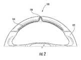
- FIG. 2is a partial view of an exemplary steering apparatus
- FIG. 3Ais a schematic cross-section view of an exemplary steering grip
- FIG. 3Bis a partial view of a top section of an exemplary steering grip
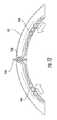
- FIG. 3Cis a schematic partial cross-section view of an exemplary steering grip and light element
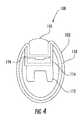
- FIG. 4is a schematic partial cross-section view of an exemplary steering grip and light element
- FIG. 5Ais a partial cross-section view of an exemplary light element
- FIG. 5Bis a partial cross-section view of an exemplary light element
- FIG. 5Cis a partial cross-section view of an exemplary light element
- FIG. 6Ais a plan view of an exemplary steering grip
- FIG. 6Bis a plan view of an exemplary steering grip
- FIG. 6Cis a plan view of an exemplary steering grip
- FIG. 6Dis a plan view of an exemplary steering grip
- FIG. 7is a partial plan view of an exemplary steering grip and light element
- FIG. 8is a partial plan view of an exemplary steering grip and light element
- FIG. 9is a partial plan view of an exemplary steering grip and light element
- FIG. 10is a partial plan view of an exemplary steering grip and light element
- FIG. 11is a partial plan view of an exemplary steering grip and light element
- FIG. 12is a partial plan view of an exemplary steering grip and light element
- FIG. 13is a schematic computer system architecture of an exemplary steering apparatus.
- FIG. 14is a schematic computer system architecture of an exemplary steering apparatus.
- FIG. 1is a partial plan view of an exemplary steering apparatus 100 having a steering grip 102 .
- the steering grip 102can be configured for gripping to facilitate control of the vehicle.
- the steering grip 102may be mounted on a fixed component (not shown) such that it is rotationally movable about a steering axis.
- An exemplary fixed componentcan include, for example, a steering column, which receives a steering spindle that extends along the steering axis and serves to transmit the rotational movement of the steering grip 102 to the wheels of the motor vehicle.
- the steering grip 102can include a single continuous grip portion or any number of unique grip sections.
- the steering grip 102can include an annular ring shape with an outer contour that is essentially circular in shape.
- the steering grip 102can define any suitable shape including, for example, circular, elliptical, square, rectangular, or any other regular or irregular shape.
- the steering apparatus 100also includes a light element 104 for providing indication and/or warning light signals to the driver of the vehicle.
- the light element 104can include, for example, a liquid crystal display (LCD), thin-film-transistor display, active-matrix display, a segmented display (e.g., improved black nematic (INB), super twisted nematic (STN), etc.), a light-emitting diode (LED), a liquid crystal display, laser, halogen, fluorescent, an infra-red (IR) LED illuminator, or any other suitable light emitting element.
- LCDliquid crystal display
- INBimproved black nematic
- STNsuper twisted nematic
- LEDlight-emitting diode
- IRinfra-red
- the light elementcan include a light pipe (not shown) having a start and end LEDs located at opposite ends of a (solid or hollow) molded plastic rod.
- the steering apparatus 100can also include a reflective material or surface for recycling light emitted from the light element 104 and can be used to direct light to the driver.
- illumination of the IR LEDmay also provide a desirable heat effect to the steering grip 102 and may direct heat towards the driver's hands.
- a steering grip 102may include a heat element, usually a heater mesh, used to provide a heat effect on the steering grip 102 .
- the heat meshmay be wrapped around the steering grip 102 and/or incorporated into the grip cover material.
- the heat meshdoes not cover over the portion of the steering grip 102 including the light element 104 thereby resulting in a gap in the heat effect.
- IR LEDsmay be used as the light element 104 to provide the heat effect in the area of the light element 104 , thereby providing a full heat effect at the surface of the steering grip 102 .
- the heat meshcovers, partially or entirely, the portion of the steering grip 102 including the light element 104 , thereby reducing and/or eliminating any gap in the heat effect.
- the light element 104can display a single color or multiple colors.
- the exemplary LEDcan include a single color LED, a bi-color LED, and a tri-color LED.
- the steering apparatus 100can include a single light element 104 or any number of light elements 104 .
- different types of light elements 104may be implemented on the same steering apparatus 100 .
- a steering grip 102may include both standard LEDs and IR LEDs.
- the light element 104can be located at any portion of the steering grip 102 .
- the light element 104can be located on an interior edge of the steering grip 102 .
- the light element 104can be located on an exterior edge of the steering grip 102 . In an alternate implementation (not shown), the light element 104 can be located on a front or back face of the steering grip 102 .
- the light element 104can be provided in a direction defined by the perimeter/diameter of the steering grip 102 . For example, as illustrated in FIG. 1 , the light element 104 can extend along the direction of the upper half of the steering grip 102 on the inner diameter of the steering grip 102 .
- the light elementcan define any suitable shape including, for example, circular, elliptical, square, rectangular, or any other regular or irregular shape. For example, as illustrated in FIG.
- the exemplary light element 104is provided with an elongated shape having curvilinear sides.
- the light element 104can include a vertical element 106 extending in a radial direction of the steering grip 102 .
- FIG. 3Aprovides a schematic side cross-section view of an exemplary steering grip 102 .
- the exemplary steering grip 102includes a light element 104 positioned on the inner diameter of the steering grip 102 .
- FIG. 3Aillustrates that the body of the steering grip 102 and the light element 104 can be sized and configured such that the body of the steering grip 102 shields the light element from ambient light 108 .
- the light element 104is shielded from ambient light 108 directed at the upper portion/top side of the steering grip 102 . Because the light element 104 is shielded from ambient light 108 , a lower intensity light signal may be used.
- a daylight warning intensity of the light element 104may be about 150 to about 800 nit. In a particular implementation, the daylight intensity of the light element 104 may be about 150 to about 500 nit. In another implementation, the daylight intensity of the light element 104 may be about 150 to about 250 nit. In another example, the daylight intensity of the light element 104 may be at least about 250 nit. In another example, the daylight intensity of the light element 104 may be at least about 150 nit. In a further exemplary implementation, because there is less ambient light at nighttime and because the light element 104 is shielding from the existing ambient light 108 , the nighttime warning intensity of the light element 104 may be at least about 5 to about 50 nit.
- the nighttime warning intensity of the light element 104may be at least about 5 to about 25 nit. In another example, the nighttime warning intensity of the light element 104 may be at least about 5 to about 15 nit. In another example, the nighttime warning intensity of the light element 104 may be at least about 5 to about 10 nit. In another example, the nighttime warning intensity of the light element 104 may be at least about 5 nit.
- a lens 110is configured to cover the light element 104 .
- the lens 110may be sized and shaped to correspond to the size and shape of the light element 104 .
- the outer surface of the lens 110may be adjacent to the exterior surface of the steering grip 102 .
- the lens 110may provide a surface that is congruent with the exterior surface of the steering grip 102 .
- the lens 110may provide an outer surface that has a different general shape than the profile defined by the steering grip 102 .
- the outer lens 110may comprise a fully or partially transparent, translucent, or opaque body.
- the outer lens 110can be constructed from a hard or soft material.
- the outer lens 110can include a surface feature or texture to provide a grip or “feel” to the driver.
- the outer lens 110can be constructed from a single layer of material or multiple layers of material.
- the outer lens 110may filter, direct, or otherwise modify the properties of the light signals emitted from the light element 104 .
- the lens 110is configured to shield the light element 104 from ambient light.
- the steering grip 102also includes a frame 112 providing the support structure for the steering grip 102 , a carrier 114 mounted to the frame 112 and configured to engage a PCB 116 and/or control circuitry for supporting and controlling operation of the light element 104 .
- the carrier 114may be sized and shaped to facilitate attachment to various frame 112 , PCB 116 , and outer lens 110 structures.
- the carrier 114can be mounted to the frame 112 using screws, hooks, clips, or any other form of mechanical fastener known in the art.
- An exemplary carrier 114may be joined with the frame 112 using a thermally conductive “gap pad” or other thermally conductive adhesive.
- the frame 112may also define the support structure for central hub and spokes of the steering grip 103 .
- the carrier 114is not required and the PCB 116 and/or control circuitry is coupled to the frame 112 of the steering grip 102 .
- an exemplary steering grip 102includes a covering 118 configured to cover the exterior of the steering grip 102 body and provide a surface for the driver to handle during operation of the vehicle.
- the covering 118may also, partially or fully, cover the lens 110 without severely impacting light transmission to the driver. It is contemplated, that, when covering the lens 110 , the covering 118 conceals the lens 110 and light element 104 when not illuminated.
- Exemplary covering 118 materialsinclude, for example, leather, cloth, polyurethane foam, and various other synthetic materials.
- the light emitted from the light element 104is filtered and guided to maximize the light signal directed through the outer lens 110 .
- light emitted from the light element 104is recycled using a solid acrylic lens 118 .
- the lens 118may be trapezoidal in shape such that light is reflected in the desired direction (i.e., at the driver).
- reflective surfaces of the carrier 114are painted white or other highly reflective color to ensure that light is reflected in the desired direction and not refracted internal to the system. Fillers and fibers can be added to the outer lens 110 and/or the lens 118 to direct light toward the driver and to increase the brightness of the light output the outer lens 110 .
- brightness enhancing films 120can be used to direct light to the driver.
- the exemplary brightness enhancing films 120may be used individually or multiple films may be stacked together. As illustrated in FIG. 5B , multiple brightness enhancing films 120 may be stacked adjacent to the lens 118 .
- diffusing films 122 and/or textured lens surfacesmay be used where high light intensity is not needed. As illustrated in FIG. 5B , diffusing films may be located adjacent to the brightness enhancing films 120 . In an alternate implementation, a diffusing film 122 may be located adjacent to the LED 116 . Light passes through the diffusing films 122 and into the brightness enhancing films 120 . Another diffusing film 122 may be located adjacent to the brightness enhancing films 120 and the lens 110 .
- the brightness of the output lightis increased.
- Any order or combination of brightness enhancing films 120 , diffusing films 122 , and lenses 118 / 110are contemplated.
- the brightness enhancing films 120 and diffusing films 122may be stacked and oriented in such a way that the ambient light entering the lens 110 cannot pass through the lens 110 . Blocking the ambient light allows the lens 110 to have a higher transmission rate while preventing internal components of the light assembly and steering grip 102 from being seen by the driver on from the outside.
- the light element 104can be associated with circuitry for controlling operation of the light signal provided by the light element 104 .
- the light element 104may be wired directly to control circuitry of the steering apparatus 100 .
- the light element 104may include a T-type LED that can be wired through an inline resistor to a steering apparatus 100 power source.
- the light element 104can be associated with a PCB (not shown) or processor mounted to or associated with the electronic control unit of the vehicle.
- the PCB/processorcan be configured to provide operation instructions from the vehicle to the light element 104 .
- the light element 104may be associated with a PCB 116 configured to provide operation instructions to the light element 104 .
- the light element 104can by physically mounted to the surface of the PCB 116 .
- the PCB 116can include, for example, rigid, semi-rigid, and flexible-type PCBs 116 .
- An example PCB 116can include a flex circuit wherein the LEDs 116 are mounted to backing material that acts as a heat sink.
- the backing materialcan include, for example, an aluminum flex backing. Other types and combinations of PCBs are contemplated.
- the PCB 116can be mounted to the steering grip 102 .
- the PCB 116 and/or control circuitryis mounted to the frame 112 of the steering grip 102 via carrier 114 .
- the PCB 116 and/control circuitryis mounted directly to the frame 112 of the steering grip 102 .
- the board material of an exemplary PCB 116may be constructed of FR-4 (G-10) glass reinforced epoxy laminate.
- FR-4has a poor thermal conductivity (approximately 0.003 W/cm ⁇ C.°)
- the frame 112may be constructed of materials having high thermal conductivity including, for example, magnesium alloy (diecast) (1.575 W/cm ⁇ C.°), aluminum alloy (diecast) (2.165 W/cm ⁇ C.°), and steel (low carbon) (0.669 W/cm ⁇ C.°)
- the PCB 116can be thermally coupled to a heat exchange component associated with the steering grip 102 .
- the heat exchange componentcan be configured to transfer heat from the PCB 116 to the steering grip 102 .
- the heat exchange componentmay comprise, for example, a thermally conductive resin, an epoxy, a polymer, and/or a metal.
- the steering grip 102may be coupled to the central hub and spokes such that heat from the light element 104 can be transferred from the steering grip 102 to the spokes and central hub of the steering grip 102 .
- the exemplary heat exchange componentIn a high intensity environment (5 nit or greater), in order to ensure driver comfort in handling the steering grip 102 and to prolong life of the light element 104 (in hours of illumination), the exemplary heat exchange component must dissipate heat from the light elements 104 at a rate sufficient to ensure that the surface temperature of the steering grip 102 does not exceed, approximately, 45° C.
- the steering apparatus 100may not include a heat exchange component.
- the heat output by the light elements 104will be not necessitate the use of a heat exchange component for dissipating heat from the light source 104 .
- the steering apparatus 100can include a single PCB 116 or multiple PCBs 116 located along the steering grip 102 .
- the steering grip 102may include a single PCB 116 spanning the entire perimeter of the steering grip 102 thereby providing a 360° illumination system.
- the steering grip 102may include a single PCB 116 along the upper half of the perimeter defined by the steering grip 102 .
- the steering grip 102may include multiple PCBs 116 .
- a steering grip 102 including multiple PCBscan provide for less likelihood that a PCB 116 will break upon impact and/or airbag deployment.
- locating multiple PCBs 116 along the diameter of the steering grip 102 , and in particular along the upper half of the steering grip rim 102helps to reduce the probability that a PCB 116 will break under a load at the 12 o'clock position on the rim of the steering wheel grip 102 . As illustrated in FIG.
- the steering grip 102may include multiple PCBs 116 , including, for example, PCB 116 A may be located on a right portion of the steering grip 102 diameter and PCB 116 B may be located on a left portion of the steering grip diameter.
- the steering grip 102may include three PCBs 116 .
- PCB 116 Amay be located on a right portion of the steering grip 102 , PCB 116 B on a left portion of the steering grip, and PCB 116 C on a top center portion of the steering grip 102 , between PCBs 116 A and 116 B.
- the steering grip 102may include a PCB 116 located on a lower portion of the steering grip 102 . Any number of locations and quantities of PCB 116 are considered within the disclosed implementation.
- the PCB 116includes a single zone or multiple zones for directing operation of the light element 104 .
- the PCB 116may include one zone for controlling operation of the light element 104 .
- the PCB 116may control the light element 104 based on instructions provided to the corresponding zone of the PCB 116 .
- the light element 104may include a single light source, such as one LED, or it may include multiple light sources, i.e., multiple LEDs.
- the PCB 116can provide separate instructions to each of the individual LEDs within the same zone.
- the PCB 116can include multiple zones, for example, two or more zones, each associated with a different light element 104 or group of light elements 104 . Each zone can be configured to provide separate operating instructions to their respective light elements 104 .
- the LEDsmay be arranged into groups and each group of LEDs assigned a zone on the PCB 116 .
- the PCB 116may include 36 LED-style light elements 104 .
- the exemplary PCB 116may be divided into four zones, each zone associated with 9 LEDs. The PCB 116 can control operation of the LEDs in each of the four zones separately based on the instructions provided by the respective zones.
- the PCB 116can include a number of zones corresponding to the number of light elements 104 present on the PCB 116 , where each zone provides operation instructions to its corresponding light individual element 104 .
- an exemplary PCB 116may include 36 LED-style light elements 104 and 36 zones corresponding to each of the 36 LEDs. The PCB can individually control operation of each of the 36 LEDs based on instructions provided to each of the corresponding 36 zones.
- the steering apparatus 100may include a processor connected in communication with the PCB 116 .
- the processormay be configured to direct operation of the light element 104 .
- the processorcan be associated with the steering apparatus 100 .
- the processormay be located on or proximate the PCB 116 of the steering grip 102 .
- the processormay be located on or otherwise associated with the electronic control unit (ECU) of the vehicle.
- the processormay be located on or otherwise associated with an other vehicle system.
- ECUelectronice control unit
- wired and/or wireless communication linesmay be provided from the alternate system to the light element 104 .
- the light element 104 and/or the PCB 116may be connected to the vehicle's electronic control unit (ECU) by a wire run from the ECU unit to the light element 104 /PCB 116 .
- ECUelectronice control unit
- particular zones on the PCB 116may communicate with a processor associated with a system other than the steering apparatus 100 and/or the steering grip 102 , and communication lines (i.e., data and/or power wires) may be provided from the alternate system to the zoned PCB 116 .
- communication linesi.e., data and/or power wires
- the light element 104 , PCB 116 , and the processorare connected in communication with the vehicle by two wires where the first wire may provide a power source to the light element 104 , PCB 116 , and the processor and the second wire provides a data connection between the steering apparatus 100 and the vehicle.
- the light element 104 , PCB 116 , and the processormay be connected in communication with the vehicle by two wires, one including multiple communication lines and the second wire including power source.
- the first wiremay include 6 communication lines for directing the operation of the corresponding zones
- the second wiremay be a power source for providing power to the PCB 116 .
- the light element 104 , PCB 116 , and the processormay, alternatively, be in communication with the vehicle at only a power source.
- the processormay be configured to receive information from the vehicle.
- Information received from the vehiclemay include, for example, GPS (global positioning system) information, navigation information, foreign object proximity information, vehicle performance information, general warning information, course information, positioning information available from on-board sensor, such as cameras, radar, LIDAR (light detection and ranging) systems, vehicle communication system information, and any other information relevant to the operation of the vehicle, the status of the user, and/or the functioning of the steering apparatus 100 .
- GPSglobal positioning system
- navigation informationfor example, navigation information, foreign object proximity information, vehicle performance information, general warning information, course information, positioning information available from on-board sensor, such as cameras, radar, LIDAR (light detection and ranging) systems, vehicle communication system information, and any other information relevant to the operation of the vehicle, the status of the user, and/or the functioning of the steering apparatus 100 .
- LIDARlight detection and ranging
- Navigation informationmay include, for example, a preparation for course change (e.g., lane recommendation in anticipation of pending course change), a navigation course change (e.g., instructions for following determined route and/or notification that the determined route has been recalculated), and a distance to course change (e.g., distance to turn).
- Foreign object proximity informationmay include, for example, the distance and direction to an identified foreign object, the size of a foreign object, and the relative speed and direction of the foreign object.
- Vehicle performance informationmay include, for example, on/off operation of the vehicle, battery life/status, fuel level, fuel efficiency, engine RPM, vehicle oversteer, vehicle understeer, turbocharger/supercharger boost pressure, an electrical vehicle (eV) status, stop and go vehicle mode, steering grip 102 straight-ahead position, vehicle lateral acceleration, autonomous vehicle driving state information, and adaptive cruise control state information.
- General vehicle warning informationmay include, for example, occupant restraint information, airbag status information, door or window open/ajar, low tire pressure, vehicle entertainment and communication system status (e.g., incoming call, Bluetooth activated, audio volume, etc.).
- Course informationmay include, for example, a measure of a course remaining (e.g., a racing lap time countdown as a binary clock, lap segments, time segments, etc.) and a measure of the course remaining/completed (e.g., quantity of racing laps).
- a measure of a course remaininge.g., a racing lap time countdown as a binary clock, lap segments, time segments, etc.
- a measure of the course remaining/completede.g., quantity of racing laps
- Operation of the light element 104may be directed in response to information received from the steering apparatus 100 and/or information received from the vehicle.
- the light element 104may be used to provide information and warning signals to the driver of the vehicle.
- the light element 104may be used to provide an aesthetically pleasing/decorative effect.
- the light element 104may be used at vehicle start up to provide a decorative effect in addition to providing an indication to the driver of the vehicle's operation status.
- Directing illumination of the light element 104may include, for example, the on/off state of the light element 104 , intensity, design/pattern, on/off illumination cycle, color, or any other feature of the light element that can be controlled or otherwise manipulated.
- the on/off status of the light element 104can be controlled.
- the quantity of light elements 104 illuminated at a given timecan be used to indicate the magnitude and/or scale of the warning or event, the greater the number illuminated the greater the threat and/or importance of the warning/event.
- the intensity of the light elements 104can be used to indicate the magnitude and/or scale of the warning or event, the greater the light intensity the greater the threat and/or importance of the warning/event.
- the on/off illumination cycle or frequency of illumination of the light element 104can also be controlled to create a flashing or strobe-like effect.
- a high frequency on/off illumination cyclemay be used to indicate an important and/or time sensitive event to the driver such as an impact or collision warning.
- the light element 104can illuminate a particular design or pattern to provide certain visual cues to the driver.
- the light element 104can illuminate a design/pattern representative of a certain image or symbol used to convey a message to the driver.
- the light element 104can illuminate in a pattern representative of navigation and/or warning information (e.g., arrow at various orientations with respect to the driver/steering apparatus 100 ).
- the light element 104can illuminate in a pattern representative of an image representative of vehicle performance (e.g., engine performance, tire status, battery, fuel, oversteer/understeer, traction control, audio, Bluetooth, etc.)
- Representative patterns/designscan include, for example, an image/icon of an engine, wheel/tire, battery, fuel gage, temperature gauge/thermostat, steering wheel, radio, Bluetooth logo, etc.
- a strobed/flashing light signalmay be used to illuminate the driver's eyes for use in camera-based driver monitoring systems.
- the operation of the exemplary IR illuminator-type light element 104may be timed in communication with a camera, or other sensing device, and a processor to capture an image of the driver's eyes.
- the use of IR LEDscan be used to mitigate light reflection when the driver is wearing eye glasses.
- the selection of a light element 104 for illumination at a certain positioncan also be used to indicate the relative position of the warning or event. For example, if an impact or collision warning is anticipated at the front driver's side section of the car, the light element 104 at a corresponding position on the steering grip 102 (i.e., upper left quadrant) may be illuminated. Similarly, the on/off illumination cycle may be used to create a motion effect. The perceived direction of the light pattern can be used to indicate the relative direction of warning.
- an on/off illumination pattern starting from the center of the steering grip 102 and progressing toward the left side of the grip 102may create an illuminated wave-like effect toward the left that can be used to indicate a warning/event associated with the left side of the vehicle or an indication to the driver of a pending course change in a navigational setting.
- a pattern of illumination of the light element 104can also be controlled.
- the light elements 104may be sized and located such that a shape or pattern may be created by illuminating particular light elements 104 .
- the color of the light element 104can also be controlled.
- the color of the light elementmay be used to indicate the severity or a threat level associated with a particular event. For example, colors such as red, yellow, and green can be used to indicate the escalating severity/threat associated with a particular event, red indicating severe, yellow a moderately severe/warning, and green little or no threat.
- controlling the color of the light element 104may be used to indicate a vehicle status or provide general driver indications. For example, colors such as blue or white may be used to indicate general vehicle status and driver indication.
- illumination combinationsare provided as exemplary and should not be considered limiting on the disclosed invention. Additional and alternative light element 104 locations and configurations are contemplated. Various combinations of light element 104 operation may be utilized to indicate the relative position and/or threat levels associated with a particular warning/event, as well as provide general status information to the driver.
- operation of the light element 104may be directed in response to information received from the vehicle and/or information received from the steering apparatus 100 .
- Information received from the vehiclecan include, for example, GPS information, on-board sensor information, camera information, communication system information, and lane position information.
- the operation of the light element 104may be directed to provide the driver with a lane departure warning.
- An exemplary lane departure warning indication wherein the light position indicates the direction of the threat eventis illustrated in FIG. 7 .
- the illuminated light element 104may be centered on the steering grip 102 (Position 1 ).
- the light elements 104 on the left side of the steering grip 102are illuminated (Position 2 ). As the vehicle moves progressively further toward the left side of the lane of travel, light elements 104 further along the left side of the steering grip 102 are illuminated (Position 3 and Position 4 ). Alternatively, as the vehicle moves to the right side of the lane of travel, the light elements 104 on right side of the steering grip are illuminated (Position 2 ). As the vehicle moves progressively further toward the right side of the lane of travel, the light elements 104 further along the right side of the steering grip are illuminated (Position 3 and Position 4 ). In an exemplary implementation, the time to lane cross may be used to determine the threat level associated with the vehicles direction of travel.
- both the quantity and position of lightsmay be used to indicate the relative position and/or threat level associated with the warning/event.
- An exemplary lane departure warning indicationwherein the quantity and position of illuminated light elements 104 are used to indicate the relative position and/or threat level of the warning or event is provided in FIG. 8 .
- the illuminated light element 104may be centered on the steering grip 102 (Position 1 ).
- information received from the vehiclee.g., GPS information, on-board sensor information, camera information, communication system information, and lane position information
- additional light elements 104 on the left side of the steering grip 102are illuminated (Position 2 ).
- additional light elements 104 further along the left side of the steering grip 102are illuminated (Position 3 and Position 4 ).
- additional light elements 104 on right side of the steering gripare illuminated (Position 2 ).
- additional light elements 104 further along the right side of the steering gripare illuminated (Position 3 and Position 4 ).
- the time to lane crossmay be used to determine the threat level associated with the vehicles direction of travel and the rate and quantity of the illumination of the additional light elements 104 are illuminated.
- the color of the illuminated light elementsmay be used to indicate the relative position and threat level associated with the warning/event.
- An exemplary lane departure warning indicationwherein the color and position of the illuminated light elements 104 are used to indicate the relative position and/or threat level of the warning or event is provided in FIG. 9 .
- the illuminated light element 104When the vehicle is in a straight ahead orientation, the illuminated light element 104 may be centered on the steering grip 102 .
- the illuminated light elementmay be provided in a color that indicates no threat/warning associated with the given lane position. As illustrated in FIG. 9 , the illuminated light element may be green when the steering grip 102 is a centered/straight ahead position (Position 1 ).
- the light elements 104 on the left side of the steering grip 102 or the light elements 104 on the right side of the steering grip 102are illuminated.
- An initial indication of lane departuremay be provided by green illuminated light elements 104 (Position 2 ).
- light elements 104 further along the left/right side of the steering grip 102are illuminated. These light elements may indicate a moderate threat/warning and may be provided, for example, by yellow illuminated light elements 104 (Position 3 ).
- the light elements 104 further along the left/right side of the steering grip 102are illuminated. These light elements may indicate a severe and/or immediate threat and may be provided, for example, by red illuminated light elements 104 (Position 4 ).
- the time to lane crossmay be used to determine the threat level associated with the vehicles direction of travel.
- the vertical element 106can include be used to indicate the relative position and threat level associated with a particular warning/event. As illustrated in FIG. 10 , the vertical element 106 may include a plurality of light elements 104 . When the vehicle is in a straight ahead orientation, the light elements 104 centered in the vertical element 106 may be illuminated (Position 1 ). Because the relative threat/warning level in the straight ahead position is minimal, the illuminated light element 104 in Position 1 may be green.
- the light elements 104 on the left or right side, respectively, of the vertical element 106are illuminated.
- an initial indication that the vehicle is tending toward the left side of the lane of travelmay be provided by illumination of the light elements 104 on the left side of the vertical element (Position 2 ).
- These light elements 104may indicate a moderate threat/warning and may be provided, for example, by yellow illuminated light elements 104 .
- the light elements 104may change colors from yellow to red, indicating that the threat level associated with the lane departure has escalated from moderate to severe and/or immediate.
- the vertical element 106can be used to indicate the relative position and/or threat level associated an impact/collision warning.
- the vertical element 106may include a plurality of light elements 104 .
- the operation of the light elements 104may be directed in response to foreign object proximity information received from the vehicle. Illumination of the light elements 104 may indicate the presence of a foreign object within a predetermined distance of the vehicle and/or a distance to the foreign object.
- the light elements 104 located on the steering grip 102illuminate. For example, as the object is approaching the light elements 104 may illuminate in a wave pattern suggesting the direction of the object and/or the proximity of the object to the vehicle.
- the light elements 104may illuminate in an illumination pattern, at a greater on/off frequency, at a particular quantity of light elements 104 , with greater intensity, and/or varying colors as the direction and/or the proximity of the object to the vehicle change.
- the vertical light element 106can be used in conjunction with the light elements 104 position on the side of the steering grip 102 .
- the light elements 104can be used to guide the driver in operation of the vehicle.
- An exemplary steering apparatus 100can be used guide a driver into a parking space.
- the light elements 104can be used to direct the driver to aim the vehicle in a particular manner.
- Operation of the light elements 104can include, for example, on/off illumination, illumination pattern, on/off cycling, intensity, and color. It is contemplated that operation of the light elements 104 of the vertical element 106 may be independent from the operation of the light elements 104 included along the diameter of the steering grip 102 .
- the light elements 104 of the vertical element 106may be used to indicate proximity to a foreign object (e.g., parked car) while the light elements 104 included along the diameter of the steering grip 102 as used to provide directional and navigation information to the user.
- the light elements 104 included along the diameter of the steering grip 102can illuminate at a location and frequency to suggest the direction of travel of the vehicle.
- the operation of the light elements 104 of the vertical element 106may be in cooperation with the light elements 104 included along the diameter of the steering grip 102 .
- both the vertical and radial light elements 104may be used to provide navigation information to suggest the direction of travel of the vehicle.
- the vertical and/or radial light elements 104may be used to indicate a difference between the posted speed limit and the actual speed of the vehicle.
- the steering apparatus 100may receive information including GPS information and vehicle performance information.
- the GPS informationmay include information associated with a posted speed limit at the vehicle's current location.
- the vehicle performance informationmay include information associated with the actual speed of the vehicle.
- the vehicle and/or the steering apparatus 100can determine that the vehicle is exceeding the posted speed limit and the operation of the light elements 104 may be directed to indicate a threat/warning associated with speed of the vehicle.
- the steering apparatusmay include a sensor (not shown) located on the steering grip 102 .
- the sensormay detect the driver input and/or touch on the steering grip.
- Exemplary sensorsinclude, for example, capacitive sensors, pressure sensors, and conductivity/resistivity sensors.
- the sensormay be in communication with the PCB 116 and/or the processor.
- the driver's inputmay be transmitted to the electronic control unit of the vehicle.
- the steering apparatus 100may be configured to receive autonomous driving state information and/or adaptive cruise control information from the vehicle.
- the autonomous driving state informationmay indicate that the vehicle is operating autonomously and not under human control.
- the adaptive cruise control informationmay include whether the adaptive cruise control feature is engaged.
- Adaptive cruise controlmaintains a set distance between the car immediately in front of the driver's vehicle and/or stops the vehicle completely when an emergency situation is identified.
- some vehiclesdirect acceleration/braking of the vehicle in addition to controlling steering (e.g., to keep the vehicle within the lane when braking).
- steeringe.g., to keep the vehicle within the lane when braking
- the autonomous driving state of the vehiclemay disengage (e.g., stop and go traffic), in these situations it is also that the driver holding the steering grip 103 .
- operation of the light element 104may be directed to indicate that the vehicle is not operating under human control or that human operation of the vehicle is necessary and the driver is required to engage the steering grip 102 .
- the steering apparatus 100also includes an acoustic display and/or a haptic display devices that work exclusively from or in conjunction with the light element 104 .
- the haptic displayscan include, for example, vibrators arranged on the steering grip 102 /steering apparatus 100 such that vibration of the steering grip 102 is felt by the driver in every grip position.
- the steering apparatus 100may be configured to direct operation of the vibrator in response to information received from the vehicle, information received from the steering grip 102 , and/or input information received from the driver at the steering grip 102 . Operation of the vibrator can include, for example manipulating the frequency and intensity the produced vibration.
- the logical operations described herein with respect to the various figuresmay be implemented (1) as a sequence of computer implemented acts or program modules (i.e., software) running on a computing device, (2) as interconnected machine logic circuits or circuit modules (i.e., hardware) within the computing device and/or (3) a combination of software and hardware of the computing device.
- the logical operations discussed hereinare not limited to any specific combination of hardware and software. The implementation is a matter of choice dependent on the performance and other requirements of the computing device. Accordingly, the logical operations described herein are referred to variously as operations, structural devices, acts, or modules. These operations, structural devices, acts and modules may be implemented in software, in firmware, in special purpose digital logic, and any combination thereof.
- FIG. 13provides an example computing device upon which embodiments of the invention may be implemented.
- the computing device 1300may include a bus or other communication mechanism for communicating information among various components of the computing device 1300 .
- computing device 1300typically includes at least one processing unit 1306 and system memory 1304 .
- system memory 1304may be volatile (such as random access memory (RAM)), non-volatile (such as read-only memory (ROM), flash memory, etc.), or some combination of the two.
- RAMrandom access memory
- ROMread-only memory
- flash memoryetc.
- the processing unit 1306may be a standard programmable processor that performs arithmetic and logic operations necessary for operation of the computing device 1300 .
- Computing device 1300may have additional features/functionality.
- computing device 1300may include additional storage such as removable storage 1308 and non-removable storage 1310 including, but not limited to, magnetic or optical disks or tapes.
- Computing device 1300may also contain network connection(s) 1316 that allow the device to communicate with other devices.
- Computing device 1300may also have input device(s) 1314 such as a keyboard, mouse, touch screen, etc.
- Output device(s) 1312such as a display, speakers, printer, etc. may also be included.
- the additional devicesmay be connected to the bus in order to facilitate communication of data among the components of the computing device 1300 . All these devices are well known in the art and need not be discussed at length here.
- the processing unit 1306may be configured to execute program code encoded in tangible, computer-readable media.
- Computer-readable mediarefers to any media that is capable of providing data that causes the computing device 1300 (i.e., a machine) to operate in a particular fashion.
- Various computer-readable mediamay be utilized to provide instructions to the processing unit 1306 for execution.
- Common forms of computer-readable mediainclude, for example, magnetic media, optical media, physical media, memory chips or cartridges, a carrier wave, or any other medium from which a computer can read.
- Example computer-readable mediamay include, but is not limited to, volatile media, non-volatile media and transmission media.
- Volatile and non-volatile mediamay be implemented in any method or technology for storage of information such as computer readable instructions, data structures, program modules or other data and common forms are discussed in detail below.
- Transmission mediamay include coaxial cables, copper wires and/or fiber optic cables, as well as acoustic or light waves, such as those generated during radio-wave and infra-red data communication.
- Example tangible, computer-readable recording mediainclude, but are not limited to, an integrated circuit (e.g., field-programmable gate array or application-specific IC), a hard disk, an optical disk, a magneto-optical disk, a floppy disk, a magnetic tape, a holographic storage medium, a solid-state device, RAM, ROM, electrically erasable program read-only memory (EEPROM), flash memory or other memory technology, CD-ROM, digital versatile disks (DVD) or other optical storage, magnetic cassettes, magnetic tape, magnetic disk storage or other magnetic storage devices.
- an integrated circuite.g., field-programmable gate array or application-specific IC
- a hard diske.g., an optical disk, a magneto-optical disk, a floppy disk, a magnetic tape, a holographic storage medium, a solid-state device, RAM, ROM, electrically erasable program read-only memory (EEPROM), flash memory or other memory technology, CD-ROM, digital versatile disks (
- the processing unit 1306may execute program code stored in the system memory 1304 .
- the busmay carry data to the system memory 1304 , from which the processing unit 1306 receives and executes instructions.
- the data received by the system memory 1304may optionally be stored on the removable storage 1308 or the non-removable storage 1310 before or after execution by the processing unit 1306 .
- Computing device 1300typically includes a variety of computer-readable media.
- Computer-readable mediacan be any available media that can be accessed by device 1300 and includes both volatile and non-volatile media, removable and non-removable media.
- Computer storage mediainclude volatile and non-volatile, and removable and non-removable media implemented in any method or technology for storage of information such as computer readable instructions, data structures, program modules or other data.
- System memory 1304 , removable storage 1308 , and non-removable storage 510are all examples of computer storage media.
- Computer storage mediainclude, but are not limited to, RAM, ROM, electrically erasable program read-only memory (EEPROM), flash memory or other memory technology, CD-ROM, digital versatile disks (DVD) or other optical storage, magnetic cassettes, magnetic tape, magnetic disk storage or other magnetic storage devices, or any other medium which can be used to store the desired information and which can be accessed by computing device 1300 . Any such computer storage media may be part of computing device 1300 .
- the various techniques described hereinmay be implemented in connection with hardware or software or, where appropriate, with a combination thereof.
- the methods and apparatuses of the presently disclosed subject matter, or certain aspects or portions thereofmay take the form of program code (i.e., instructions) embodied in tangible media, such as floppy diskettes, CD-ROMs, hard drives, or any other machine-readable storage medium wherein, when the program code is loaded into and executed by a machine, such as a computing device, the machine becomes an apparatus for practicing the presently disclosed subject matter.
- the computing deviceIn the case of program code execution on programmable computers, the computing device generally includes a processor, a storage medium readable by the processor (including volatile and non-volatile memory and/or storage elements), at least one input device, and at least one output device.
- One or more programsmay implement or utilize the processes described in connection with the presently disclosed subject matter, e.g., through the use of an application programming interface (API), reusable controls, or the like.
- APIapplication programming interface
- Such programsmay be implemented in a high level procedural or object-oriented programming language to communicate with a computer system.
- the program(s)can be implemented in assembly or machine language, if desired. In any case, the language may be a compiled or interpreted language and it may be combined with hardware implementations.
- FIG. 14provides schematic illustration of an exemplary computer architecture upon which the invention may be implemented.
- the computing device 1400may include a processing unit 1406 and a memory 1404 .
- the memory 1404may include various registers. Exemplary registers may include an LED enable register, an LED location register, and LED color register, and an LED intensity register.
- the computing device 1400may include a light element driver for providing illumination instructions to the light element 104 .
- the computing device 1400may include a bus 1402 or other communication mechanism for communicating information among various components of the computing device 1400 .
- the bus 1402may provide a communication link between the computing device 1400 and the vehicle.
- the bus 1402may provide a communication link between the computing device 1400 and various vehicle components.
- Information transmitted by the bus 1402may include, for example, lane departure warning signal information, GPS signal information, general warning signal information, and vehicle performance indication signal information.
- An exemplary implementationmay include a clock spring 1408 associated with the processing unit 1406 and the communication bus 1402 .
- the clock spring 1408may provide an electrical connection/communication link between when the processing unit 1406 is located proximate the steering grip 102 /steering apparatus 100 .
- An exemplary clock spring 1408includes a rotary-type electrical connection that permits rotation of the steering grip 102 while maintaining an electrical connection with the bus 1402 .
- the clock spring 1408may include a static element, generally mounted to the steering column, and a rotating element, generally mounted to the steering grip 102 .
Landscapes
- Engineering & Computer Science (AREA)
- Mechanical Engineering (AREA)
- Chemical & Material Sciences (AREA)
- Combustion & Propulsion (AREA)
- Transportation (AREA)
- Human Computer Interaction (AREA)
- Steering Controls (AREA)
- Lighting Device Outwards From Vehicle And Optical Signal (AREA)
- Illuminated Signs And Luminous Advertising (AREA)
Abstract
Description
Claims (18)
Priority Applications (2)
| Application Number | Priority Date | Filing Date | Title |
|---|---|---|---|
| US15/075,519US9821703B2 (en) | 2012-10-23 | 2016-03-21 | Steering wheel light bar |
| US15/722,512US10059250B2 (en) | 2012-10-23 | 2017-10-02 | Steering wheel light bar |
Applications Claiming Priority (3)
| Application Number | Priority Date | Filing Date | Title |
|---|---|---|---|
| US201261717542P | 2012-10-23 | 2012-10-23 | |
| US14/061,383US9308856B2 (en) | 2012-10-23 | 2013-10-23 | Steering wheel light bar |
| US15/075,519US9821703B2 (en) | 2012-10-23 | 2016-03-21 | Steering wheel light bar |
Related Parent Applications (1)
| Application Number | Title | Priority Date | Filing Date |
|---|---|---|---|
| US14/061,383ContinuationUS9308856B2 (en) | 2012-10-23 | 2013-10-23 | Steering wheel light bar |
Related Child Applications (1)
| Application Number | Title | Priority Date | Filing Date |
|---|---|---|---|
| US15/722,512ContinuationUS10059250B2 (en) | 2012-10-23 | 2017-10-02 | Steering wheel light bar |
Publications (2)
| Publication Number | Publication Date |
|---|---|
| US20160200343A1 US20160200343A1 (en) | 2016-07-14 |
| US9821703B2true US9821703B2 (en) | 2017-11-21 |
Family
ID=50484839
Family Applications (3)
| Application Number | Title | Priority Date | Filing Date |
|---|---|---|---|
| US14/061,383ActiveUS9308856B2 (en) | 2012-10-23 | 2013-10-23 | Steering wheel light bar |
| US15/075,519ActiveUS9821703B2 (en) | 2012-10-23 | 2016-03-21 | Steering wheel light bar |
| US15/722,512ActiveUS10059250B2 (en) | 2012-10-23 | 2017-10-02 | Steering wheel light bar |
Family Applications Before (1)
| Application Number | Title | Priority Date | Filing Date |
|---|---|---|---|
| US14/061,383ActiveUS9308856B2 (en) | 2012-10-23 | 2013-10-23 | Steering wheel light bar |
Family Applications After (1)
| Application Number | Title | Priority Date | Filing Date |
|---|---|---|---|
| US15/722,512ActiveUS10059250B2 (en) | 2012-10-23 | 2017-10-02 | Steering wheel light bar |
Country Status (5)
| Country | Link |
|---|---|
| US (3) | US9308856B2 (en) |
| JP (1) | JP6394603B2 (en) |
| CN (2) | CN110877568B (en) |
| DE (1) | DE112013005118T5 (en) |
| WO (1) | WO2014066477A1 (en) |
Cited By (9)
| Publication number | Priority date | Publication date | Assignee | Title |
|---|---|---|---|---|
| US20170166116A1 (en)* | 2015-12-14 | 2017-06-15 | Toyoda Gosei Co., Ltd. | Steering wheel |
| US10696217B2 (en) | 2017-01-04 | 2020-06-30 | Joyson Safety Systems Acquisition | Vehicle illumination systems and methods |
| US10780908B2 (en) | 2014-07-23 | 2020-09-22 | Joyson Safety Systems Acquisition Llc | Steering grip light bar systems |
| US11130443B1 (en) | 2020-12-09 | 2021-09-28 | Autoliv Asp, Inc. | Light bar assemblies for a steering wheel |
| US11198387B1 (en) | 2020-12-09 | 2021-12-14 | Autoliv Asp, Inc. | Heat dissipation of a light bar assembly of a steering wheel |
| US11267499B1 (en) | 2020-12-09 | 2022-03-08 | Autoliv Asp, Inc. | Wrapping for a steering wheel |
| US11312294B1 (en) | 2020-12-10 | 2022-04-26 | Autolive Asp, Inc. | Light bar assemblies for a steering wheel |
| US11390211B2 (en)* | 2020-01-17 | 2022-07-19 | Toyoda Gosei Co., Ltd. | Steering wheel |
| US11772700B2 (en) | 2018-03-08 | 2023-10-03 | Joyson Safety Systems Acquisition Llc | Vehicle illumination systems and methods |
Families Citing this family (96)
| Publication number | Priority date | Publication date | Assignee | Title |
|---|---|---|---|---|
| CN104736412B (en) | 2012-10-23 | 2018-06-29 | Tk控股公司 | Steering wheel lamp bar |
| DE112013005126T5 (en) | 2012-10-23 | 2015-07-16 | Tk Holdings Inc. | Steering Wheel lightbar |
| WO2014066477A1 (en) | 2012-10-23 | 2014-05-01 | Tk Holdings Inc. | Steering wheel light bar |
| US9463736B2 (en) | 2013-11-21 | 2016-10-11 | Ford Global Technologies, Llc | Illuminated steering assembly |
| US9481297B2 (en) | 2013-11-21 | 2016-11-01 | Ford Global Technologies, Llc | Illuminated steering assembly |
| EP2907730B1 (en) | 2014-01-29 | 2017-09-06 | Steering Solutions IP Holding Corporation | Hands on steering wheel detect |
| MX353483B (en)* | 2014-03-26 | 2018-01-16 | Nissan Motor | Vehicular information provision device. |
| JP2016032257A (en)* | 2014-07-30 | 2016-03-07 | 株式会社デンソー | Driver monitoring device |
| US10532659B2 (en) | 2014-12-30 | 2020-01-14 | Joyson Safety Systems Acquisition Llc | Occupant monitoring systems and methods |
| US9533687B2 (en) | 2014-12-30 | 2017-01-03 | Tk Holdings Inc. | Occupant monitoring systems and methods |
| US10614328B2 (en) | 2014-12-30 | 2020-04-07 | Joyson Safety Acquisition LLC | Occupant monitoring systems and methods |
| US9580012B2 (en)* | 2015-03-02 | 2017-02-28 | Tk Holdings Inc. | Vehicle object detection and notification system |
| JP6237685B2 (en)* | 2015-04-01 | 2017-11-29 | トヨタ自動車株式会社 | Vehicle control device |
| WO2016172709A1 (en)* | 2015-04-24 | 2016-10-27 | Tk Holdings Inc. | Steering wheel light bar |
| USD806729S1 (en) | 2015-04-24 | 2018-01-02 | Tk Holdings, Inc. | Display screen with graphical user interface |
| US10351159B2 (en) | 2015-05-01 | 2019-07-16 | Steering Solutions Ip Holding Corporation | Retractable steering column with a radially projecting attachment |
| US10589774B2 (en) | 2015-05-01 | 2020-03-17 | Steering Solutions Ip Holding Corporation | Counter rotation steering wheel |
| US9919724B2 (en) | 2015-05-29 | 2018-03-20 | Steering Solutions Ip Holding Corporation | Retractable steering column with manual retrieval |
| US10343706B2 (en) | 2015-06-11 | 2019-07-09 | Steering Solutions Ip Holding Corporation | Retractable steering column system, vehicle having the same, and method |
| US11560169B2 (en) | 2015-06-11 | 2023-01-24 | Steering Solutions Ip Holding Corporation | Retractable steering column system and method |
| DE102016110791A1 (en) | 2015-06-15 | 2016-12-15 | Steering Solutions Ip Holding Corporation | Gesture control for a retractable steering wheel |
| CN106256651B (en) | 2015-06-16 | 2019-06-04 | 操纵技术Ip控股公司 | Retractable steering column assembly and method |
| US9828016B2 (en) | 2015-06-24 | 2017-11-28 | Steering Solutions Ip Holding Corporation | Retractable steering column system, vehicle having the same, and method |
| DE102016111473A1 (en) | 2015-06-25 | 2016-12-29 | Steering Solutions Ip Holding Corporation | STATIONARY STEERING WHEEL ASSEMBLY AND METHOD |
| US20160375931A1 (en) | 2015-06-25 | 2016-12-29 | Steering Solutions Ip Holding Corporation | Rotation control system for a steering wheel and method |
| US9944307B2 (en) | 2015-06-26 | 2018-04-17 | Steering Solutions Ip Holding Corporation | Steering assembly and method of monitoring a space within vehicle |
| US10112639B2 (en) | 2015-06-26 | 2018-10-30 | Steering Solutions Ip Holding Corporation | Vehicle steering arrangement and method of making same |
| US9840271B2 (en) | 2015-06-29 | 2017-12-12 | Steering Solutions Ip Holding Corporation | Retractable steering column with rake limiter |
| DE102015110381A1 (en)* | 2015-06-29 | 2016-12-29 | Valeo Schalter Und Sensoren Gmbh | Method for operating a driver assistance system for a motor vehicle with representation of an optical warning signal on a display element of a steering handle, driver assistance system and motor vehicle |
| US9845103B2 (en) | 2015-06-29 | 2017-12-19 | Steering Solutions Ip Holding Corporation | Steering arrangement |
| US9849904B2 (en) | 2015-07-31 | 2017-12-26 | Steering Solutions Ip Holding Corporation | Retractable steering column with dual actuators |
| US9845106B2 (en) | 2015-08-31 | 2017-12-19 | Steering Solutions Ip Holding Corporation | Overload protection for belt drive mechanism |
| US10160472B2 (en) | 2015-10-20 | 2018-12-25 | Steering Solutions Ip Holding Corporation | Steering column with stationary hub |
| US9809155B2 (en) | 2015-10-27 | 2017-11-07 | Steering Solutions Ip Holding Corporation | Retractable steering column assembly having lever, vehicle having retractable steering column assembly, and method |
| US10029725B2 (en) | 2015-12-03 | 2018-07-24 | Steering Solutions Ip Holding Corporation | Torque feedback system for a steer-by-wire vehicle, vehicle having steering column, and method of providing feedback in vehicle |
| US10082791B2 (en)* | 2016-01-26 | 2018-09-25 | GM Global Technology Operations LLC | Autonomous vehicle control system and method |
| DE102016001178A1 (en)* | 2016-02-03 | 2017-08-03 | Audi Ag | motor vehicle |
| FR3047718B1 (en)* | 2016-02-17 | 2019-07-12 | Autoliv Development Ab | WHEEL OF VEHICLE |
| US10322682B2 (en) | 2016-03-03 | 2019-06-18 | Steering Solutions Ip Holding Corporation | Steering wheel with keyboard |
| KR101806675B1 (en)* | 2016-03-25 | 2017-12-07 | 현대자동차주식회사 | Stitchless leather steering wheel |
| US10496102B2 (en) | 2016-04-11 | 2019-12-03 | Steering Solutions Ip Holding Corporation | Steering system for autonomous vehicle |
| DE102017108692B4 (en) | 2016-04-25 | 2024-09-26 | Steering Solutions Ip Holding Corporation | Control of an electric power steering system using system state predictions |
| US10396584B2 (en)* | 2016-04-25 | 2019-08-27 | Visteon Global Technologies, Inc. | Wireless charging steering wheel |
| CN105799768A (en)* | 2016-05-09 | 2016-07-27 | 北京新能源汽车股份有限公司 | Steering wheel and vehicle with same |
| US10351161B2 (en) | 2016-05-27 | 2019-07-16 | Steering Solutions Ip Holding Corporation | Steering column with manual retraction |
| CN107521547B (en) | 2016-06-21 | 2020-03-10 | 操纵技术Ip控股公司 | Self-locking telescopic actuator for steering column assembly |
| US10457313B2 (en) | 2016-06-28 | 2019-10-29 | Steering Solutions Ip Holding Corporation | ADAS wheel locking device |
| US10363958B2 (en) | 2016-07-26 | 2019-07-30 | Steering Solutions Ip Holding Corporation | Electric power steering mode determination and transitioning |
| US10160477B2 (en) | 2016-08-01 | 2018-12-25 | Steering Solutions Ip Holding Corporation | Electric power steering column assembly |
| CN106184504A (en)* | 2016-08-19 | 2016-12-07 | 广东濠绅科技有限公司 | A kind of intelligent child's bicycle with light prompting function |
| US10189496B2 (en) | 2016-08-22 | 2019-01-29 | Steering Solutions Ip Holding Corporation | Steering assembly having a telescope drive lock assembly |
| US10384708B2 (en) | 2016-09-12 | 2019-08-20 | Steering Solutions Ip Holding Corporation | Intermediate shaft assembly for steer-by-wire steering system |
| US10160473B2 (en) | 2016-09-13 | 2018-12-25 | Steering Solutions Ip Holding Corporation | Steering column decoupling system |
| US10144383B2 (en) | 2016-09-29 | 2018-12-04 | Steering Solutions Ip Holding Corporation | Steering wheel with video screen and airbag |
| US10399591B2 (en) | 2016-10-03 | 2019-09-03 | Steering Solutions Ip Holding Corporation | Steering compensation with grip sensing |
| JP6461066B2 (en)* | 2016-10-13 | 2019-01-30 | 矢崎総業株式会社 | Production lighting device for vehicle |
| US10239552B2 (en) | 2016-10-14 | 2019-03-26 | Steering Solutions Ip Holding Corporation | Rotation control assembly for a steering column |
| US10481602B2 (en) | 2016-10-17 | 2019-11-19 | Steering Solutions Ip Holding Corporation | Sensor fusion for autonomous driving transition control |
| CN109890684B (en)* | 2016-10-26 | 2021-09-28 | 本田技研工业株式会社 | Vehicle control device |
| US10421475B2 (en) | 2016-11-15 | 2019-09-24 | Steering Solutions Ip Holding Corporation | Electric actuator mechanism for retractable steering column assembly with manual override |
| US10310605B2 (en) | 2016-11-15 | 2019-06-04 | Steering Solutions Ip Holding Corporation | Haptic feedback for steering system controls |
| US9862403B1 (en) | 2016-11-29 | 2018-01-09 | Steering Solutions Ip Holding Corporation | Manually retractable steering column assembly for autonomous vehicle |
| US10351160B2 (en) | 2016-11-30 | 2019-07-16 | Steering Solutions Ip Holding Corporation | Steering column assembly having a sensor assembly |
| US10780915B2 (en) | 2016-12-07 | 2020-09-22 | Steering Solutions Ip Holding Corporation | Vehicle steering system having a user experience based automated driving to manual driving transition system and method |
| USD847190S1 (en) | 2017-01-04 | 2019-04-30 | Joyson Safety Systems Acquisition Llc | Steering wheel display screen with graphical user interface |
| US10370022B2 (en) | 2017-02-13 | 2019-08-06 | Steering Solutions Ip Holding Corporation | Steering column assembly for autonomous vehicle |
| US10385930B2 (en) | 2017-02-21 | 2019-08-20 | Steering Solutions Ip Holding Corporation | Ball coupling assembly for steering column assembly |
| DE102017204529A1 (en) | 2017-03-17 | 2018-09-20 | Volkswagen Aktiengesellschaft | Arrangement for attentiveness control of the driver of a vehicle and method for driving a device for attentiveness control of the driver of a vehicle |
| US10449927B2 (en) | 2017-04-13 | 2019-10-22 | Steering Solutions Ip Holding Corporation | Steering system having anti-theft capabilities |
| DE102017208762A1 (en)* | 2017-05-23 | 2018-11-29 | Bayerische Motoren Werke Aktiengesellschaft | Driving system for automated driving with means for marking areas on the steering wheel and corresponding method |
| DE102017208763A1 (en) | 2017-05-23 | 2018-11-29 | Bayerische Motoren Werke Aktiengesellschaft | A driving system for automated driving with a steering wheel display for displaying the distance to an end point for automated driving and method for displaying the distance |
| DE102018112814B4 (en) | 2017-06-01 | 2022-02-24 | Joyson Safety Systems Germany Gmbh | vehicle lighting device |
| JP6525352B2 (en)* | 2017-09-29 | 2019-06-05 | 株式会社Subaru | Driving support device and driving support method |
| DE102017218402A1 (en) | 2017-10-13 | 2019-04-18 | Joyson Safety Systems Germany Gmbh | Steering wheel arrangement for a motor vehicle |
| EP3486140B1 (en) | 2017-11-20 | 2021-01-20 | Steering Solutions IP Holding Corporation | Vision based active steering system |
| US10875566B2 (en) | 2018-03-22 | 2020-12-29 | Steering Solutions Ip Holding Corporation | Stow release assembly for a manually adjustable steering column assembly |
| CN110539691A (en)* | 2018-05-28 | 2019-12-06 | 长城汽车股份有限公司 | Steering wheel rotation reminding device and steering wheel |
| US10974756B2 (en) | 2018-07-31 | 2021-04-13 | Steering Solutions Ip Holding Corporation | Clutch device latching system and method |
| US10884249B2 (en)* | 2018-10-23 | 2021-01-05 | Panasonic Automotive Systems Company Of America, Division Of Panasonic Corporation Of North America | Combiner head up display with separate infrared function |
| EP3894275B1 (en) | 2018-12-11 | 2025-04-02 | Ess-Help, Inc. | Enhanced operation of vehicle hazard and lighting communication systems |
| CN109720271A (en)* | 2018-12-28 | 2019-05-07 | 广州小鹏汽车科技有限公司 | A kind of steering wheel modulated structure and steering wheel |
| DE102019202020B4 (en)* | 2019-02-15 | 2022-05-25 | Hyundai Motor Company | Steering control device with an indicator light system for a motor vehicle and method for operating an indicator light system of a steering control device |
| CA3133773A1 (en)* | 2019-03-15 | 2020-09-24 | Ess-Help, Inc. | Control of high visibility vehicle light communication systems |
| CN111746387A (en)* | 2019-03-28 | 2020-10-09 | 上海擎感智能科技有限公司 | Vehicle-mounted road deviation prompting method, device and system |
| AU2020248490B2 (en) | 2019-03-28 | 2021-11-18 | Emergency Safety Solutions, Inc. | Remote vehicle hazard and communication beacon |
| US11325523B2 (en) | 2019-04-02 | 2022-05-10 | Pony Ai Inc. | Lighting element control for an autonomous vehicle |
| US11180079B2 (en)* | 2020-01-07 | 2021-11-23 | Joyson Safety Systems Acquisition Llc | Steering wheel assembly with covered light source |
| US11263890B1 (en) | 2020-09-01 | 2022-03-01 | Carol Garwood | Vehicle occupancy reminder |
| CN112498536B (en)* | 2020-11-26 | 2021-11-30 | 安徽辰吉新能源科技有限公司 | Automatic steering system of steering headlamp |
| CN112572598A (en)* | 2020-12-18 | 2021-03-30 | 赵洁 | Combined switch mounted on automobile steering column |
| US11634071B2 (en) | 2021-01-12 | 2023-04-25 | Ford Global Technologies, Llc | Trailer sideswipe avoidance system |
| DE102021103067A1 (en) | 2021-02-10 | 2022-08-11 | Bayerische Motoren Werke Aktiengesellschaft | WARNING ISSUE FOR MOTOR VEHICLE |
| EP4335679A1 (en)* | 2022-09-06 | 2024-03-13 | KNORR-BREMSE Systeme für Nutzfahrzeuge GmbH | System and method for providing well distinguishable warning levels for obstacles in different visibility areas in the vicinity of a vehicle |
| US12221036B2 (en) | 2022-10-05 | 2025-02-11 | Ford Global Technologies, Llc | Trailer sideswipe avoidance system |
| JP2024087590A (en)* | 2022-12-19 | 2024-07-01 | 豊田合成株式会社 | Steering Wheel |
| US20240367666A1 (en)* | 2023-05-01 | 2024-11-07 | Fca Us Llc | Steering input with light source |
Citations (95)
| Publication number | Priority date | Publication date | Assignee | Title |
|---|---|---|---|---|
| US3485974A (en) | 1968-05-20 | 1969-12-23 | Switches Inc | Momentary contact switches for control of accessory circuits |
| US4664127A (en)* | 1984-08-28 | 1987-05-12 | Aisin Seiki Kabushiki Kaisha | Vehicle-loaded heartbeat meter |
| US4835512A (en) | 1988-03-07 | 1989-05-30 | Bratton Daniel W | Steering wheel high beam headlight indicator |
| US4993281A (en) | 1989-05-05 | 1991-02-19 | Miller Jess J | Flexible steering wheel heat shield |
| US5203226A (en) | 1990-04-17 | 1993-04-20 | Toyoda Gosei Co., Ltd. | Steering wheel provided with luminous display device |
| US5516143A (en) | 1994-06-20 | 1996-05-14 | Morton International, Inc. | Windowed airbag cover |
| US5558364A (en) | 1995-06-07 | 1996-09-24 | Larry J. Winget | Plastic air bag cover having an integrated light source |
| FR2744976A1 (en) | 1996-02-19 | 1997-08-22 | Renault | STEERING WHEEL FOR A MOTOR VEHICLE WHICH A SECTOR OF THE RIM CONTAINS MEANS OF INFORMATION |
| US5661839A (en) | 1996-03-22 | 1997-08-26 | The University Of British Columbia | Light guide employing multilayer optical film |
| US5666102A (en) | 1996-07-24 | 1997-09-09 | United Technologies Automotive Systems, Inc. | Vehicle signals incorporated into steering wheel rim |
| EP0801373A1 (en) | 1996-01-16 | 1997-10-15 | Lumitex, Inc. | Light emitting panel assemblies for use in automotive applications and the like |
| JPH1059190A (en) | 1996-08-23 | 1998-03-03 | Toyoda Gosei Co Ltd | Steering wheel device |
| JP2000153769A (en) | 1998-11-19 | 2000-06-06 | Nissan Motor Co Ltd | Automatic vehicle steering system |
| DE20018732U1 (en) | 2000-10-30 | 2001-01-11 | Petri Ag, 63743 Aschaffenburg | Steering wheel for motor vehicles |
| US6190026B1 (en) | 1997-10-24 | 2001-02-20 | Matthew G. Moore | Illuminated automotive emblem |
| JP2001055149A (en) | 1999-08-17 | 2001-02-27 | Toyoda Gosei Co Ltd | Steering wheel with indicator |
| US6296380B1 (en) | 1999-03-18 | 2001-10-02 | Aboud Dawli | Lighted steering wheel |
| DE20014731U1 (en) | 2000-08-25 | 2002-01-17 | R.D.I. Deutschland Autoteile + Vertriebs Gmbh, 58313 Herdecke | Steering wheel for motor vehicles |
| US20020068605A1 (en) | 2000-08-03 | 2002-06-06 | Stanley Winfield Scott | Manual mobile-communication interface |
| DE10113493A1 (en) | 2001-03-19 | 2002-09-26 | Bayerische Motoren Werke Ag | Vehicle steering wheel incorporates light conductors, especially in the wheel skeleton, to indicate the steering setting under all light conditions and also give visual warnings on the status of battery or oil pressure and the like |
| WO2002096745A1 (en) | 2001-05-30 | 2002-12-05 | Secto Design & Innovation | Control unit |
| US6538405B1 (en) | 2000-04-28 | 2003-03-25 | The Cherry Corporation | Accessory control system |
| US20030121360A1 (en) | 2000-05-24 | 2003-07-03 | Takata-Petri Ag | Steering-wheel cover |
| US6651526B1 (en) | 1999-09-06 | 2003-11-25 | Yamaha Corporation | Steering wheel and manufacturing method therefor |
| US6668682B1 (en) | 1998-07-23 | 2003-12-30 | Takata-Petri Ag | Steering wheel comprising a decorative covering |
| US6703999B1 (en) | 2000-11-13 | 2004-03-09 | Toyota Jidosha Kabushiki Kaisha | System for computer user interface |
| US20040045396A1 (en) | 2000-10-03 | 2004-03-11 | Makoto Hosokawa | Composite molded article, steering wheel and production method therefor |
| JP2004148911A (en) | 2002-10-29 | 2004-05-27 | Yazaki Corp | Display device in steering |
| US6768067B2 (en) | 2002-11-01 | 2004-07-27 | Kabushiki Kaisha Tokai Rika Denki Seisakusho | Switch device in steering wheel and steering wheel |
| US6817100B2 (en) | 2000-10-25 | 2004-11-16 | Kabushiki Kaisha Tokai-Rika Denki Seisakusho | Steering wheel and method for manufacturing steering wheel |
| US20050021190A1 (en) | 2003-07-24 | 2005-01-27 | Worrell Barry C. | Method and apparatus for accessing vehicle systems |
| WO2005025936A2 (en) | 2003-09-18 | 2005-03-24 | Fumio Watanabe | Steering wheel for vehicle, vehicle, and direction indication device |
| US20050189159A1 (en) | 2004-02-10 | 2005-09-01 | Takata-Petri Ag | Steering wheel for a motor vehicle |
| US20060070795A1 (en) | 2003-04-04 | 2006-04-06 | Takata-Petri Ag | Steering wheel for motor vehicles |
| WO2006076903A1 (en) | 2005-01-19 | 2006-07-27 | Takata-Petri Ag | Steering wheel assembly for a motor vehicle |
| DE102005013202A1 (en) | 2005-03-16 | 2006-09-28 | Takata-Petri Ag | Steering wheel switch has piezoelectric force or capacitive contact sensors arranged under steering wheel lining or airbag module cover and aligned individually to operating switches on lining or cover |
| US20060236807A1 (en) | 2005-03-17 | 2006-10-26 | Toyoda Gosei Co., Ltd. | Steering wheel |
| WO2006127835A2 (en) | 2005-05-25 | 2006-11-30 | Spectrum Cubic, Inc. | Vehicle steering wheel and method for making same |
| US7143663B2 (en) | 2003-01-30 | 2006-12-05 | Key Safety Systems, Inc. | Steering wheel with thermoplastic composites |
| US7173536B2 (en) | 2004-08-28 | 2007-02-06 | Landon Duval | Substance detection and alarm using a spectrometer built into a steering wheel assembly |
| JP2007114379A (en) | 2005-10-19 | 2007-05-10 | Toyota Motor Corp | Electronics |
| JP2007153048A (en) | 2005-12-02 | 2007-06-21 | Nippon Plast Co Ltd | Steering wheel with indicator |
| US20080061954A1 (en) | 2006-08-30 | 2008-03-13 | Kulas Charles J | Visual indicators on vehicle steering |
| US7377186B2 (en) | 2004-07-26 | 2008-05-27 | Transbiotec, Inc. | Engagement of a sensor system with a vehicle operating device |
| US7468656B1 (en) | 2005-03-29 | 2008-12-23 | Frank Donald E | Rear-end collision warning light system |
| JP2009018722A (en) | 2007-07-12 | 2009-01-29 | Panasonic Corp | In-vehicle information presentation device |
| US20090063053A1 (en) | 2007-09-04 | 2009-03-05 | International Business Machines Corporation | Method and system for blind spot identification and warning utilizing visual indicators |
| US20090096937A1 (en) | 2007-08-16 | 2009-04-16 | Bauer Frederick T | Vehicle Rearview Assembly Including a Display for Displaying Video Captured by a Camera and User Instructions |
| US7525449B1 (en) | 2003-10-20 | 2009-04-28 | Teleflex Megatech, Inc. | Status light for switch on boat steering wheel |
| US20090189373A1 (en) | 2005-08-10 | 2009-07-30 | Schramm Michael R | Steering Apparatus |
| US20090223321A1 (en) | 2004-07-30 | 2009-09-10 | Ferrari S.P.A. | Vehicle Steering Wheel |
| WO2009111098A2 (en) | 2008-03-02 | 2009-09-11 | Altair Engineering, Inc. | Lens and heatsink assembly for a led light tube |
| US20090319095A1 (en) | 2008-06-20 | 2009-12-24 | Tk Holdings Inc. | Vehicle driver messaging system and method |
| JP2010017007A (en) | 2008-07-04 | 2010-01-21 | Yazaki Corp | Charge monitoring device |
| CN101639181A (en) | 2009-08-07 | 2010-02-03 | 广东昭信光电科技有限公司 | Direct type backlighting system |
| US7672759B1 (en) | 2004-02-24 | 2010-03-02 | Teleflex Megatech, Inc. | Communication with a steering wheel switch |
| US7679495B2 (en) | 2003-06-02 | 2010-03-16 | Robert Bosch Gmbh | Displaying unit and method for displaying a steering-wheel angle, to be modified, of a motor vehicle |
| US7680574B2 (en) | 2004-03-04 | 2010-03-16 | Gm Global Technology Operations, Inc. | Vehicle information system with steering wheel controller |
| WO2010051090A1 (en) | 2008-10-27 | 2010-05-06 | Autoliv Asp, Inc. | Method for illuminating colors in a backlit driver airbag emblem |
| US20100107806A1 (en) | 2007-01-26 | 2010-05-06 | Corinaldi Alessandro Alcide Gi | Vehicle Steering-Wheel Cover |
| CN201487849U (en) | 2009-09-07 | 2010-05-26 | 南京汉德森科技股份有限公司 | Heat sink substrate for AC LED light source |
| WO2010087931A1 (en) | 2009-01-30 | 2010-08-05 | Autoliv Asp, Inc. | Methods for illumination of driver airbag emblems |
| US7786886B2 (en) | 2006-12-15 | 2010-08-31 | Hyundai Motor Company | Display system and method for steering wheel of vehicle |
| US20100218641A1 (en) | 2007-09-06 | 2010-09-02 | Delf Neumann | Steering wheel assembly for a motor vehicle |
| JP2010241275A (en) | 2009-04-06 | 2010-10-28 | Honda Motor Co Ltd | Vehicle steering wheel |
| WO2010131305A1 (en) | 2009-05-15 | 2010-11-18 | パナソニック株式会社 | Electric power line communication apparatus and electric power line communication system |
| US20110153160A1 (en) | 2007-09-06 | 2011-06-23 | Takata-Petri Ag | Steering wheel assembly for a motor vehicle |
| US7969531B1 (en) | 2007-03-08 | 2011-06-28 | Jabil Circuit, Inc. | Integrated multi-function light guide for LCD backlighting |
| US7987030B2 (en) | 2005-05-25 | 2011-07-26 | GM Global Technology Operations LLC | Vehicle illumination system and method |
| US20110187518A1 (en) | 2010-02-02 | 2011-08-04 | Ford Global Technologies, Llc | Steering wheel human/machine interface system and method |
| US7997612B2 (en) | 2006-09-04 | 2011-08-16 | Autoliv Development Ab | Steering wheel arrangement |
| US20110198999A1 (en) | 2008-10-20 | 2011-08-18 | Koninklijke Philips Electronics N.V. | Led light |
| US20110198201A1 (en) | 2010-02-12 | 2011-08-18 | Chuang Chih-Kai | Steering wheel having a direction light button |
| US8061861B2 (en) | 2008-10-27 | 2011-11-22 | Autoliv Asp, Inc. | Method for illuminating colors in a backlit driver airbag emblem |
| US8067709B2 (en) | 2008-05-26 | 2011-11-29 | Daesung Electric Co., Ltd | Haptic steering wheel switch device and haptic steering wheel switch system including the same |
| US20120013490A1 (en) | 2010-07-19 | 2012-01-19 | Apple Inc. | Illumination of input device |
| US8136425B2 (en) | 2005-11-10 | 2012-03-20 | Tk Holdings Inc. | Back light of steering wheel |
| JP2012093584A (en) | 2010-10-27 | 2012-05-17 | Toyota Central R&D Labs Inc | Optical coupler, optical scanner and spectrometer |
| US20120146776A1 (en) | 2010-12-14 | 2012-06-14 | Honda Motor Co., Ltd. | In-vehicle power line communication system |
| US20120150387A1 (en)* | 2010-12-10 | 2012-06-14 | Tk Holdings Inc. | System for monitoring a vehicle driver |
| US8210564B2 (en) | 2008-11-19 | 2012-07-03 | Trw Automotive Safety Systems Gmbh | Interior lining part for a motor vehicle |
| CN202371573U (en) | 2011-11-28 | 2012-08-08 | 广州市芯光元光电科技有限公司 | Underwater LED (Light-Emitting Diode) lamp |
| US8269452B2 (en) | 2008-07-04 | 2012-09-18 | Yazaki Corporation | Battery charge monitoring device |
| US20120267222A1 (en) | 2011-04-25 | 2012-10-25 | Daesung Electric Co., Ltd. | Haptic steering wheel switch apparatus |
| US20130152721A1 (en) | 2011-12-15 | 2013-06-20 | Chrysler Group Llc | Steering wheel damper and alternate power storage device |
| US20140109719A1 (en) | 2012-10-23 | 2014-04-24 | Tk Holdings, Inc. | Steering Wheel Light Bar |
| US20140111324A1 (en) | 2012-10-23 | 2014-04-24 | Tk Holding, Inc. | Steering Wheel Light Bar |
| US20140111325A1 (en) | 2012-10-23 | 2014-04-24 | Tk Holdings, Inc. | Steering Wheel Light Bar |
| US20140111736A1 (en) | 2012-10-24 | 2014-04-24 | Samsung Electronics Co., Ltd. | Curved display apparatus |
| US8761565B1 (en) | 2009-04-16 | 2014-06-24 | Fusion Optix, Inc. | Arcuate lightguide and light emitting device comprising the same |
| US20140244115A1 (en) | 2013-02-25 | 2014-08-28 | Denso Corporation | Driving support apparatus |
| US20140375785A1 (en)* | 2013-06-19 | 2014-12-25 | Raytheon Company | Imaging-based monitoring of stress and fatigue |
| US9134729B1 (en) | 2010-04-28 | 2015-09-15 | Google Inc. | User interface for displaying internal state of autonomous driving system |
| US9223638B2 (en) | 2012-09-24 | 2015-12-29 | Sap Se | Lockless spin buffer |
| US20160257248A1 (en) | 2015-03-02 | 2016-09-08 | Tk Holdings Inc. | Vehicle object detection and notification system |
Family Cites Families (1)
| Publication number | Priority date | Publication date | Assignee | Title |
|---|---|---|---|---|
| JP2010143391A (en)* | 2008-12-18 | 2010-07-01 | Tokai Rika Co Ltd | Direction indicator |
- 2013
- 2013-10-23WOPCT/US2013/066330patent/WO2014066477A1/enactiveApplication Filing
- 2013-10-23JPJP2015538153Apatent/JP6394603B2/enactiveActive
- 2013-10-23CNCN201911223739.8Apatent/CN110877568B/enactiveActive
- 2013-10-23CNCN201380055394.4Apatent/CN104755354B/enactiveActive
- 2013-10-23USUS14/061,383patent/US9308856B2/enactiveActive
- 2013-10-23DEDE112013005118.4Tpatent/DE112013005118T5/enactivePending
- 2016
- 2016-03-21USUS15/075,519patent/US9821703B2/enactiveActive
- 2017
- 2017-10-02USUS15/722,512patent/US10059250B2/enactiveActive
Patent Citations (114)
| Publication number | Priority date | Publication date | Assignee | Title |
|---|---|---|---|---|
| US3485974A (en) | 1968-05-20 | 1969-12-23 | Switches Inc | Momentary contact switches for control of accessory circuits |
| US4664127A (en)* | 1984-08-28 | 1987-05-12 | Aisin Seiki Kabushiki Kaisha | Vehicle-loaded heartbeat meter |
| US4835512A (en) | 1988-03-07 | 1989-05-30 | Bratton Daniel W | Steering wheel high beam headlight indicator |
| US4993281A (en) | 1989-05-05 | 1991-02-19 | Miller Jess J | Flexible steering wheel heat shield |
| US5203226A (en) | 1990-04-17 | 1993-04-20 | Toyoda Gosei Co., Ltd. | Steering wheel provided with luminous display device |
| US5516143A (en) | 1994-06-20 | 1996-05-14 | Morton International, Inc. | Windowed airbag cover |
| US5558364A (en) | 1995-06-07 | 1996-09-24 | Larry J. Winget | Plastic air bag cover having an integrated light source |
| EP0801373A1 (en) | 1996-01-16 | 1997-10-15 | Lumitex, Inc. | Light emitting panel assemblies for use in automotive applications and the like |
| US5895115A (en) | 1996-01-16 | 1999-04-20 | Lumitex, Inc. | Light emitting panel assemblies for use in automotive applications and the like |
| FR2744976A1 (en) | 1996-02-19 | 1997-08-22 | Renault | STEERING WHEEL FOR A MOTOR VEHICLE WHICH A SECTOR OF THE RIM CONTAINS MEANS OF INFORMATION |
| US5661839A (en) | 1996-03-22 | 1997-08-26 | The University Of British Columbia | Light guide employing multilayer optical film |
| US5666102A (en) | 1996-07-24 | 1997-09-09 | United Technologies Automotive Systems, Inc. | Vehicle signals incorporated into steering wheel rim |
| WO1998003365A1 (en) | 1996-07-24 | 1998-01-29 | Ut Automotive Dearborn, Inc. | Display unit on a vehicle steering wheel |
| JPH1059190A (en) | 1996-08-23 | 1998-03-03 | Toyoda Gosei Co Ltd | Steering wheel device |
| US6190026B1 (en) | 1997-10-24 | 2001-02-20 | Matthew G. Moore | Illuminated automotive emblem |
| US6668682B1 (en) | 1998-07-23 | 2003-12-30 | Takata-Petri Ag | Steering wheel comprising a decorative covering |
| JP2000153769A (en) | 1998-11-19 | 2000-06-06 | Nissan Motor Co Ltd | Automatic vehicle steering system |
| US6296380B1 (en) | 1999-03-18 | 2001-10-02 | Aboud Dawli | Lighted steering wheel |
| JP2001055149A (en) | 1999-08-17 | 2001-02-27 | Toyoda Gosei Co Ltd | Steering wheel with indicator |
| US6651526B1 (en) | 1999-09-06 | 2003-11-25 | Yamaha Corporation | Steering wheel and manufacturing method therefor |
| US6538405B1 (en) | 2000-04-28 | 2003-03-25 | The Cherry Corporation | Accessory control system |
| US20030121360A1 (en) | 2000-05-24 | 2003-07-03 | Takata-Petri Ag | Steering-wheel cover |
| US20020068605A1 (en) | 2000-08-03 | 2002-06-06 | Stanley Winfield Scott | Manual mobile-communication interface |
| DE20014731U1 (en) | 2000-08-25 | 2002-01-17 | R.D.I. Deutschland Autoteile + Vertriebs Gmbh, 58313 Herdecke | Steering wheel for motor vehicles |
| US20040045396A1 (en) | 2000-10-03 | 2004-03-11 | Makoto Hosokawa | Composite molded article, steering wheel and production method therefor |
| US6817100B2 (en) | 2000-10-25 | 2004-11-16 | Kabushiki Kaisha Tokai-Rika Denki Seisakusho | Steering wheel and method for manufacturing steering wheel |
| DE20018732U1 (en) | 2000-10-30 | 2001-01-11 | Petri Ag, 63743 Aschaffenburg | Steering wheel for motor vehicles |
| US6703999B1 (en) | 2000-11-13 | 2004-03-09 | Toyota Jidosha Kabushiki Kaisha | System for computer user interface |
| DE10113493A1 (en) | 2001-03-19 | 2002-09-26 | Bayerische Motoren Werke Ag | Vehicle steering wheel incorporates light conductors, especially in the wheel skeleton, to indicate the steering setting under all light conditions and also give visual warnings on the status of battery or oil pressure and the like |
| WO2002096745A1 (en) | 2001-05-30 | 2002-12-05 | Secto Design & Innovation | Control unit |
| JP2004148911A (en) | 2002-10-29 | 2004-05-27 | Yazaki Corp | Display device in steering |
| US6768067B2 (en) | 2002-11-01 | 2004-07-27 | Kabushiki Kaisha Tokai Rika Denki Seisakusho | Switch device in steering wheel and steering wheel |
| US7143663B2 (en) | 2003-01-30 | 2006-12-05 | Key Safety Systems, Inc. | Steering wheel with thermoplastic composites |
| US7414520B2 (en) | 2003-04-04 | 2008-08-19 | Takata-Petri Ag | Steering wheel for motor vehicles |
| US20060070795A1 (en) | 2003-04-04 | 2006-04-06 | Takata-Petri Ag | Steering wheel for motor vehicles |
| US7679495B2 (en) | 2003-06-02 | 2010-03-16 | Robert Bosch Gmbh | Displaying unit and method for displaying a steering-wheel angle, to be modified, of a motor vehicle |
| US20050021190A1 (en) | 2003-07-24 | 2005-01-27 | Worrell Barry C. | Method and apparatus for accessing vehicle systems |
| JP2005088792A (en) | 2003-09-18 | 2005-04-07 | Fumio Watanabe | Steering wheel for vehicle and vehicle |
| WO2005025936A2 (en) | 2003-09-18 | 2005-03-24 | Fumio Watanabe | Steering wheel for vehicle, vehicle, and direction indication device |
| US7525449B1 (en) | 2003-10-20 | 2009-04-28 | Teleflex Megatech, Inc. | Status light for switch on boat steering wheel |
| US20050189159A1 (en) | 2004-02-10 | 2005-09-01 | Takata-Petri Ag | Steering wheel for a motor vehicle |
| US7672759B1 (en) | 2004-02-24 | 2010-03-02 | Teleflex Megatech, Inc. | Communication with a steering wheel switch |
| US7680574B2 (en) | 2004-03-04 | 2010-03-16 | Gm Global Technology Operations, Inc. | Vehicle information system with steering wheel controller |
| US7377186B2 (en) | 2004-07-26 | 2008-05-27 | Transbiotec, Inc. | Engagement of a sensor system with a vehicle operating device |
| US20090223321A1 (en) | 2004-07-30 | 2009-09-10 | Ferrari S.P.A. | Vehicle Steering Wheel |
| US7173536B2 (en) | 2004-08-28 | 2007-02-06 | Landon Duval | Substance detection and alarm using a spectrometer built into a steering wheel assembly |
| US20080023253A1 (en) | 2005-01-19 | 2008-01-31 | Takata-Petri Ag | Steering wheel assembly for a motor vehicle |
| US7605694B2 (en) | 2005-01-19 | 2009-10-20 | Takata-Petri Ag | Steering wheel assembly for a motor vehicle |
| US7602278B2 (en) | 2005-01-19 | 2009-10-13 | Takata-Petri Ag | Steering wheel assembly for a motor vehicle |
| WO2006076903A1 (en) | 2005-01-19 | 2006-07-27 | Takata-Petri Ag | Steering wheel assembly for a motor vehicle |
| DE102005013202A1 (en) | 2005-03-16 | 2006-09-28 | Takata-Petri Ag | Steering wheel switch has piezoelectric force or capacitive contact sensors arranged under steering wheel lining or airbag module cover and aligned individually to operating switches on lining or cover |
| US20060236807A1 (en) | 2005-03-17 | 2006-10-26 | Toyoda Gosei Co., Ltd. | Steering wheel |
| US7468656B1 (en) | 2005-03-29 | 2008-12-23 | Frank Donald E | Rear-end collision warning light system |
| US7987030B2 (en) | 2005-05-25 | 2011-07-26 | GM Global Technology Operations LLC | Vehicle illumination system and method |
| WO2006127835A2 (en) | 2005-05-25 | 2006-11-30 | Spectrum Cubic, Inc. | Vehicle steering wheel and method for making same |
| US20080202282A1 (en) | 2005-05-25 | 2008-08-28 | Spectrum Cubic, Inc. | Vehicle Steering Wheel and Method For Making Same |
| US20090189373A1 (en) | 2005-08-10 | 2009-07-30 | Schramm Michael R | Steering Apparatus |
| JP2007114379A (en) | 2005-10-19 | 2007-05-10 | Toyota Motor Corp | Electronics |
| US8136425B2 (en) | 2005-11-10 | 2012-03-20 | Tk Holdings Inc. | Back light of steering wheel |
| JP2007153048A (en) | 2005-12-02 | 2007-06-21 | Nippon Plast Co Ltd | Steering wheel with indicator |
| US20080061954A1 (en) | 2006-08-30 | 2008-03-13 | Kulas Charles J | Visual indicators on vehicle steering |
| US7605693B2 (en) | 2006-08-30 | 2009-10-20 | Kulas Charles J | Visual indicators on vehicle steering wheel displayed in response to hand position |
| US7997612B2 (en) | 2006-09-04 | 2011-08-16 | Autoliv Development Ab | Steering wheel arrangement |
| US7786886B2 (en) | 2006-12-15 | 2010-08-31 | Hyundai Motor Company | Display system and method for steering wheel of vehicle |
| US20100107806A1 (en) | 2007-01-26 | 2010-05-06 | Corinaldi Alessandro Alcide Gi | Vehicle Steering-Wheel Cover |
| US7969531B1 (en) | 2007-03-08 | 2011-06-28 | Jabil Circuit, Inc. | Integrated multi-function light guide for LCD backlighting |
| JP2009018722A (en) | 2007-07-12 | 2009-01-29 | Panasonic Corp | In-vehicle information presentation device |
| US20090096937A1 (en) | 2007-08-16 | 2009-04-16 | Bauer Frederick T | Vehicle Rearview Assembly Including a Display for Displaying Video Captured by a Camera and User Instructions |
| US20090063053A1 (en) | 2007-09-04 | 2009-03-05 | International Business Machines Corporation | Method and system for blind spot identification and warning utilizing visual indicators |
| US8645001B2 (en) | 2007-09-04 | 2014-02-04 | International Business Machines Corporation | Method and system for blind spot identification and warning utilizing visual indicators |
| US20110153160A1 (en) | 2007-09-06 | 2011-06-23 | Takata-Petri Ag | Steering wheel assembly for a motor vehicle |
| US20100218641A1 (en) | 2007-09-06 | 2010-09-02 | Delf Neumann | Steering wheel assembly for a motor vehicle |
| WO2009111098A2 (en) | 2008-03-02 | 2009-09-11 | Altair Engineering, Inc. | Lens and heatsink assembly for a led light tube |
| US8067709B2 (en) | 2008-05-26 | 2011-11-29 | Daesung Electric Co., Ltd | Haptic steering wheel switch device and haptic steering wheel switch system including the same |
| US20090319095A1 (en) | 2008-06-20 | 2009-12-24 | Tk Holdings Inc. | Vehicle driver messaging system and method |
| CN102066181A (en) | 2008-06-20 | 2011-05-18 | Tk控股公司 | Vehicle driver messaging system and method |
| JP2010017007A (en) | 2008-07-04 | 2010-01-21 | Yazaki Corp | Charge monitoring device |
| US8269452B2 (en) | 2008-07-04 | 2012-09-18 | Yazaki Corporation | Battery charge monitoring device |
| US20110198999A1 (en) | 2008-10-20 | 2011-08-18 | Koninklijke Philips Electronics N.V. | Led light |
| US8061861B2 (en) | 2008-10-27 | 2011-11-22 | Autoliv Asp, Inc. | Method for illuminating colors in a backlit driver airbag emblem |
| WO2010051090A1 (en) | 2008-10-27 | 2010-05-06 | Autoliv Asp, Inc. | Method for illuminating colors in a backlit driver airbag emblem |
| US8210564B2 (en) | 2008-11-19 | 2012-07-03 | Trw Automotive Safety Systems Gmbh | Interior lining part for a motor vehicle |
| WO2010087931A1 (en) | 2009-01-30 | 2010-08-05 | Autoliv Asp, Inc. | Methods for illumination of driver airbag emblems |
| JP2010241275A (en) | 2009-04-06 | 2010-10-28 | Honda Motor Co Ltd | Vehicle steering wheel |
| US8761565B1 (en) | 2009-04-16 | 2014-06-24 | Fusion Optix, Inc. | Arcuate lightguide and light emitting device comprising the same |
| WO2010131305A1 (en) | 2009-05-15 | 2010-11-18 | パナソニック株式会社 | Electric power line communication apparatus and electric power line communication system |
| CN101639181A (en) | 2009-08-07 | 2010-02-03 | 广东昭信光电科技有限公司 | Direct type backlighting system |
| CN201487849U (en) | 2009-09-07 | 2010-05-26 | 南京汉德森科技股份有限公司 | Heat sink substrate for AC LED light source |
| CN201998981U (en) | 2010-02-02 | 2011-10-05 | 福特环球技术公司 | Human/machine interface system for motor vehicle |
| US20110187518A1 (en) | 2010-02-02 | 2011-08-04 | Ford Global Technologies, Llc | Steering wheel human/machine interface system and method |
| US20110198201A1 (en) | 2010-02-12 | 2011-08-18 | Chuang Chih-Kai | Steering wheel having a direction light button |
| US9134729B1 (en) | 2010-04-28 | 2015-09-15 | Google Inc. | User interface for displaying internal state of autonomous driving system |
| US20120013490A1 (en) | 2010-07-19 | 2012-01-19 | Apple Inc. | Illumination of input device |
| JP2012093584A (en) | 2010-10-27 | 2012-05-17 | Toyota Central R&D Labs Inc | Optical coupler, optical scanner and spectrometer |
| US20120150387A1 (en)* | 2010-12-10 | 2012-06-14 | Tk Holdings Inc. | System for monitoring a vehicle driver |
| JP2012129742A (en) | 2010-12-14 | 2012-07-05 | Honda Motor Co Ltd | Power line communication device for vehicle |
| US20120146776A1 (en) | 2010-12-14 | 2012-06-14 | Honda Motor Co., Ltd. | In-vehicle power line communication system |
| US20120267222A1 (en) | 2011-04-25 | 2012-10-25 | Daesung Electric Co., Ltd. | Haptic steering wheel switch apparatus |
| CN202371573U (en) | 2011-11-28 | 2012-08-08 | 广州市芯光元光电科技有限公司 | Underwater LED (Light-Emitting Diode) lamp |
| US20130152721A1 (en) | 2011-12-15 | 2013-06-20 | Chrysler Group Llc | Steering wheel damper and alternate power storage device |
| US9223638B2 (en) | 2012-09-24 | 2015-12-29 | Sap Se | Lockless spin buffer |
| WO2014066476A1 (en) | 2012-10-23 | 2014-05-01 | Tk Holdings Inc. | Steering wheel light bar |
| WO2014066477A1 (en) | 2012-10-23 | 2014-05-01 | Tk Holdings Inc. | Steering wheel light bar |
| US20140111325A1 (en) | 2012-10-23 | 2014-04-24 | Tk Holdings, Inc. | Steering Wheel Light Bar |
| WO2014066512A1 (en) | 2012-10-23 | 2014-05-01 | Tk Holdings Inc. | Steering wheel light bar |
| US20140111324A1 (en) | 2012-10-23 | 2014-04-24 | Tk Holding, Inc. | Steering Wheel Light Bar |
| US20140109719A1 (en) | 2012-10-23 | 2014-04-24 | Tk Holdings, Inc. | Steering Wheel Light Bar |
| US9308856B2 (en) | 2012-10-23 | 2016-04-12 | Tk Holdings, Inc. | Steering wheel light bar |
| US9308857B2 (en) | 2012-10-23 | 2016-04-12 | Tk Holdings Inc. | Steering wheel light bar |
| US20160200246A1 (en) | 2012-10-23 | 2016-07-14 | Tk Holdings Inc. | Steering wheel light bar |
| US20140111736A1 (en) | 2012-10-24 | 2014-04-24 | Samsung Electronics Co., Ltd. | Curved display apparatus |
| US20140244115A1 (en) | 2013-02-25 | 2014-08-28 | Denso Corporation | Driving support apparatus |
| US20140375785A1 (en)* | 2013-06-19 | 2014-12-25 | Raytheon Company | Imaging-based monitoring of stress and fatigue |
| US20160257248A1 (en) | 2015-03-02 | 2016-09-08 | Tk Holdings Inc. | Vehicle object detection and notification system |
Non-Patent Citations (29)
| Title |
|---|
| Co-pending U.S. Appl. No. 15/075,527, filed Mar. 21, 2016. |
| English translation of the International Preliminary Report on Patentability (Chapter I or Chapter II of the Patent Cooperation Treaty) from the International Bureau of WIPO for International Application No. PCT/DE2008/001527 dated Apr. 7, 2010, 17 pages. |
| Final Office Action, dated Aug. 25, 2015, received in connection with U.S. Appl. No. 14/061,383. |
| Final Office Action, dated Aug. 25, 2015, received in connection with U.S. Appl. No. 14/061,408. |
| International Preliminary Report on Patentability, Apr. 28, 2015, received in connection with International Patent Application No. PCT/US2013/066329. |
| International Preliminary Report on Patentability, Apr. 28, 2015, received in connection with International Patent Application No. PCT/US2013/066330. |
| International Search Report and Written Opinion conducted in International Application No. PCT/US2016/29218, dated Aug. 5, 2016. |
| International Search Report and Written Opinion dated, Feb. 7, 2014, received in connection with International Patent Application No. PCT/US2013/066329. |
| International Search Report and Written Opinion dated, Feb. 7, 2014, received in connection with International Patent Application No. PCT/US2013/066330. |
| International Search Report and Written Opinion, dated Feb. 7, 2014, received in connection with International Patent Application No. PCT/US2013/066399. |
| Non final office action for U.S. Appl. No. 14/061,383 dated Feb. 18, 2015. |
| Non-Final Office Action issued in U.S. Appl. No. 14/806,325, dated May 11, 2017. |
| Non-final Office Action, dated Feb. 18, 2015, received in connection with U.S. Appl. No. 14/061,383. |
| Non-final Office Action, dated Feb. 18, 2015, received in connection with U.S. Appl. No. 14/061,408. |
| Non-final Office Action, dated Mar. 13, 2015, received in connection with U.S. Appl. No. 14/061,397. |
| Office Action in U.S. Appl. No. 14/307,780, dated Mar. 28, 2017. |
| Office Action in U.S. Appl. No. 14/307,780, dated Oct. 28, 2016. |
| Office Action issued in Chinese Application No. 201380055391.0, dated Jun. 29, 2016. |
| Office Action issued in Chinese Application No. 201380055394.4, dated Jun. 28, 2016. |
| Office Action issued in Chinese Application No. 201380055405.9, dated Jun. 2, 2016. |
| Office Action issued in counterpart Japanese Application No. 2010-523275 dated Jun. 5, 2012 (2 pages) and an English translation of the same (1 page). |
| Office Action issued in Japanese Application No. JP2015-538152, dated Aug. 29, 2017. |
| Office Action issued in Japanese Application No. JP2015-538153, dated Aug. 29, 2017. |
| Office Action issued in Japanese Application No. JP2015-538159, dated Aug. 29, 2017. |
| Office Action issued in U.S. Appl. No. 15/075,527, dated Sep. 20, 2016. |
| PCT/US2013/066329, filed Oct. 23, 2013, International Search Report and Written Opinion dated Feb. 7, 2014. |
| PCT/US2013/066399, filed Oct. 23, 2013, International Search Report and Written Opinion dated Feb. 7, 2014. |
| Second Office Action issued in Chinese Application No. 201380055391.0, dated Apr. 19, 2017. |
| Third Office Action issued in Chinese Application No. 201380055394.4, dated Sep. 8, 2017. |
Cited By (15)
| Publication number | Priority date | Publication date | Assignee | Title |
|---|---|---|---|---|
| US12344303B2 (en) | 2014-07-23 | 2025-07-01 | Joyson Safety Systems Acquisition Llc | Steering grip light bar systems |
| US10780908B2 (en) | 2014-07-23 | 2020-09-22 | Joyson Safety Systems Acquisition Llc | Steering grip light bar systems |
| US11834093B2 (en) | 2014-07-23 | 2023-12-05 | Joyson Safety Systems Acquisition Llc | Steering grip light bar systems |
| US11242080B2 (en) | 2014-07-23 | 2022-02-08 | Joyson Safety Systems Acquisition Llc | Steering grip light bar systems |
| US20170166116A1 (en)* | 2015-12-14 | 2017-06-15 | Toyoda Gosei Co., Ltd. | Steering wheel |
| US10246012B2 (en)* | 2015-12-14 | 2019-04-02 | Toyoda Gosei Co., Ltd. | Steering wheel |
| US11208037B2 (en) | 2017-01-04 | 2021-12-28 | Joyson Safety Systems Acquisition Llc | Vehicle illumination systems and methods |
| US10696217B2 (en) | 2017-01-04 | 2020-06-30 | Joyson Safety Systems Acquisition | Vehicle illumination systems and methods |
| US11772700B2 (en) | 2018-03-08 | 2023-10-03 | Joyson Safety Systems Acquisition Llc | Vehicle illumination systems and methods |
| US12122443B2 (en) | 2018-03-08 | 2024-10-22 | Joyson Safety Systems Acquisition Llc | Vehicle illumination systems and methods |
| US11390211B2 (en)* | 2020-01-17 | 2022-07-19 | Toyoda Gosei Co., Ltd. | Steering wheel |
| US11198387B1 (en) | 2020-12-09 | 2021-12-14 | Autoliv Asp, Inc. | Heat dissipation of a light bar assembly of a steering wheel |
| US11267499B1 (en) | 2020-12-09 | 2022-03-08 | Autoliv Asp, Inc. | Wrapping for a steering wheel |
| US11130443B1 (en) | 2020-12-09 | 2021-09-28 | Autoliv Asp, Inc. | Light bar assemblies for a steering wheel |
| US11312294B1 (en) | 2020-12-10 | 2022-04-26 | Autolive Asp, Inc. | Light bar assemblies for a steering wheel |
Also Published As
| Publication number | Publication date |
|---|---|
| CN104755354A (en) | 2015-07-01 |
| JP6394603B2 (en) | 2018-09-26 |
| JP2016501760A (en) | 2016-01-21 |
| US10059250B2 (en) | 2018-08-28 |
| CN110877568A (en) | 2020-03-13 |
| US20140111324A1 (en) | 2014-04-24 |
| US20180118089A1 (en) | 2018-05-03 |
| DE112013005118T5 (en) | 2015-08-27 |
| US9308856B2 (en) | 2016-04-12 |
| CN110877568B (en) | 2023-05-05 |
| CN104755354B (en) | 2019-12-06 |
| US20160200343A1 (en) | 2016-07-14 |
| WO2014066477A1 (en) | 2014-05-01 |
Similar Documents
| Publication | Publication Date | Title |
|---|---|---|
| US10059250B2 (en) | Steering wheel light bar | |
| US10179541B2 (en) | Steering wheel light bar | |
| US9233638B2 (en) | Steering wheel light bar | |
| US10036843B2 (en) | Steering wheel light bar | |
| US11208037B2 (en) | Vehicle illumination systems and methods | |
| US11772700B2 (en) | Vehicle illumination systems and methods |
Legal Events
| Date | Code | Title | Description |
|---|---|---|---|
| AS | Assignment | Owner name:TK HOLDINGS INC., MICHIGAN Free format text:ASSIGNMENT OF ASSIGNORS INTEREST;ASSIGNORS:LISSEMAN, JASON CARL;GARDNER, VALERIE DAWN;VAN'TZELFDE, DWAYNE;AND OTHERS;SIGNING DATES FROM 20121030 TO 20121113;REEL/FRAME:038114/0119 | |
| STCF | Information on status: patent grant | Free format text:PATENTED CASE | |
| AS | Assignment | Owner name:DEUTSCHE BANK TRUST COMPANY AMERICAS, NEW YORK Free format text:INTELLECTUAL PROPERTY SECURITY AGREEMENT SUPPLEMENT;ASSIGNOR:JOYSON SAFETY SYSTEMS ACQUISITION LLC;REEL/FRAME:045959/0305 Effective date:20180410 | |
| AS | Assignment | Owner name:JOYSON SAFETY SYSTEMS ACQUISITION LLC, MICHIGAN Free format text:ASSIGNMENT OF ASSIGNORS INTEREST;ASSIGNOR:TK HOLDINGS INC.;REEL/FRAME:046173/0180 Effective date:20180410 | |
| MAFP | Maintenance fee payment | Free format text:PAYMENT OF MAINTENANCE FEE, 4TH YEAR, LARGE ENTITY (ORIGINAL EVENT CODE: M1551); ENTITY STATUS OF PATENT OWNER: LARGE ENTITY Year of fee payment:4 | |
| AS | Assignment | Owner name:DEUTSCHE BANK TRUST COMPANY AMERICAS, AS SECURITY AGENT FOR THE SECURED PARTIES, NEW YORK Free format text:SECURITY INTEREST;ASSIGNOR:JOYSON SAFETY SYSTEMS ACQUISITION LLC;REEL/FRAME:057828/0411 Effective date:20211004 Owner name:JOYSON SAFETY SYSTEMS ACQUISITION LLC, MICHIGAN Free format text:RELEASE BY SECURED PARTY;ASSIGNOR:DEUTSCHE BANK TRUST COMPANY AMERICAS, AS SECURITY AGENT FOR THE SECURED PARTIES;REEL/FRAME:057775/0726 Effective date:20211004 | |
| MAFP | Maintenance fee payment | Free format text:PAYMENT OF MAINTENANCE FEE, 8TH YEAR, LARGE ENTITY (ORIGINAL EVENT CODE: M1552); ENTITY STATUS OF PATENT OWNER: LARGE ENTITY Year of fee payment:8 |