US9821097B2 - Body cavity drainage devices including drainage tubes having inline portions and related methods - Google Patents
Body cavity drainage devices including drainage tubes having inline portions and related methodsDownload PDFInfo
- Publication number
- US9821097B2 US9821097B2US14/318,568US201414318568AUS9821097B2US 9821097 B2US9821097 B2US 9821097B2US 201414318568 AUS201414318568 AUS 201414318568AUS 9821097 B2US9821097 B2US 9821097B2
- Authority
- US
- United States
- Prior art keywords
- drainage tube
- body cavity
- cavity drainage
- activation apparatus
- distal end
- Prior art date
- Legal status (The legal status is an assumption and is not a legal conclusion. Google has not performed a legal analysis and makes no representation as to the accuracy of the status listed.)
- Active, expires
Links
Images


Classifications
- A61M1/008—
- A—HUMAN NECESSITIES
- A61—MEDICAL OR VETERINARY SCIENCE; HYGIENE
- A61B—DIAGNOSIS; SURGERY; IDENTIFICATION
- A61B1/00—Instruments for performing medical examinations of the interior of cavities or tubes of the body by visual or photographical inspection, e.g. endoscopes; Illuminating arrangements therefor
- A61B1/005—Flexible endoscopes
- A61B1/0051—Flexible endoscopes with controlled bending of insertion part
- A61B1/0052—Constructional details of control elements, e.g. handles
- A—HUMAN NECESSITIES
- A61—MEDICAL OR VETERINARY SCIENCE; HYGIENE
- A61B—DIAGNOSIS; SURGERY; IDENTIFICATION
- A61B1/00—Instruments for performing medical examinations of the interior of cavities or tubes of the body by visual or photographical inspection, e.g. endoscopes; Illuminating arrangements therefor
- A61B1/00163—Optical arrangements
- A61B1/00165—Optical arrangements with light-conductive means, e.g. fibre optics
- A—HUMAN NECESSITIES
- A61—MEDICAL OR VETERINARY SCIENCE; HYGIENE
- A61B—DIAGNOSIS; SURGERY; IDENTIFICATION
- A61B1/00—Instruments for performing medical examinations of the interior of cavities or tubes of the body by visual or photographical inspection, e.g. endoscopes; Illuminating arrangements therefor
- A61B1/04—Instruments for performing medical examinations of the interior of cavities or tubes of the body by visual or photographical inspection, e.g. endoscopes; Illuminating arrangements therefor combined with photographic or television appliances
- A61B1/042—Instruments for performing medical examinations of the interior of cavities or tubes of the body by visual or photographical inspection, e.g. endoscopes; Illuminating arrangements therefor combined with photographic or television appliances characterised by a proximal camera, e.g. a CCD camera
- A—HUMAN NECESSITIES
- A61—MEDICAL OR VETERINARY SCIENCE; HYGIENE
- A61B—DIAGNOSIS; SURGERY; IDENTIFICATION
- A61B90/00—Instruments, implements or accessories specially adapted for surgery or diagnosis and not covered by any of the groups A61B1/00 - A61B50/00, e.g. for luxation treatment or for protecting wound edges
- A61B90/36—Image-producing devices or illumination devices not otherwise provided for
- A61B90/37—Surgical systems with images on a monitor during operation
- A—HUMAN NECESSITIES
- A61—MEDICAL OR VETERINARY SCIENCE; HYGIENE
- A61M—DEVICES FOR INTRODUCING MEDIA INTO, OR ONTO, THE BODY; DEVICES FOR TRANSDUCING BODY MEDIA OR FOR TAKING MEDIA FROM THE BODY; DEVICES FOR PRODUCING OR ENDING SLEEP OR STUPOR
- A61M1/00—Suction or pumping devices for medical purposes; Devices for carrying-off, for treatment of, or for carrying-over, body-liquids; Drainage systems
- A61M1/84—Drainage tubes; Aspiration tips
- A—HUMAN NECESSITIES
- A61—MEDICAL OR VETERINARY SCIENCE; HYGIENE
- A61M—DEVICES FOR INTRODUCING MEDIA INTO, OR ONTO, THE BODY; DEVICES FOR TRANSDUCING BODY MEDIA OR FOR TAKING MEDIA FROM THE BODY; DEVICES FOR PRODUCING OR ENDING SLEEP OR STUPOR
- A61M25/00—Catheters; Hollow probes
- A61M25/01—Introducing, guiding, advancing, emplacing or holding catheters
- A61M25/0105—Steering means as part of the catheter or advancing means; Markers for positioning
- A61M25/0133—Tip steering devices
- A61M25/0136—Handles therefor
- A—HUMAN NECESSITIES
- A61—MEDICAL OR VETERINARY SCIENCE; HYGIENE
- A61M—DEVICES FOR INTRODUCING MEDIA INTO, OR ONTO, THE BODY; DEVICES FOR TRANSDUCING BODY MEDIA OR FOR TAKING MEDIA FROM THE BODY; DEVICES FOR PRODUCING OR ENDING SLEEP OR STUPOR
- A61M25/00—Catheters; Hollow probes
- A61M25/01—Introducing, guiding, advancing, emplacing or holding catheters
- A61M25/0105—Steering means as part of the catheter or advancing means; Markers for positioning
- A61M25/0133—Tip steering devices
- A61M25/0147—Tip steering devices with movable mechanical means, e.g. pull wires
- A—HUMAN NECESSITIES
- A61—MEDICAL OR VETERINARY SCIENCE; HYGIENE
- A61B—DIAGNOSIS; SURGERY; IDENTIFICATION
- A61B17/00—Surgical instruments, devices or methods
- A61B17/00234—Surgical instruments, devices or methods for minimally invasive surgery
- A61B2017/00292—Surgical instruments, devices or methods for minimally invasive surgery mounted on or guided by flexible, e.g. catheter-like, means
- A61B2017/003—Steerable
- A61B2017/00318—Steering mechanisms
- A61B2017/00323—Cables or rods
- A61B2017/00327—Cables or rods with actuating members moving in opposite directions
- A—HUMAN NECESSITIES
- A61—MEDICAL OR VETERINARY SCIENCE; HYGIENE
- A61B—DIAGNOSIS; SURGERY; IDENTIFICATION
- A61B50/00—Containers, covers, furniture or holders specially adapted for surgical or diagnostic appliances or instruments, e.g. sterile covers
- A61B2050/005—Containers, covers, furniture or holders specially adapted for surgical or diagnostic appliances or instruments, e.g. sterile covers with a lid or cover
- A—HUMAN NECESSITIES
- A61—MEDICAL OR VETERINARY SCIENCE; HYGIENE
- A61B—DIAGNOSIS; SURGERY; IDENTIFICATION
- A61B50/00—Containers, covers, furniture or holders specially adapted for surgical or diagnostic appliances or instruments, e.g. sterile covers
- A61B50/30—Containers specially adapted for packaging, protecting, dispensing, collecting or disposing of surgical or diagnostic appliances or instruments
- A61B2050/314—Flexible bags or pouches
- A—HUMAN NECESSITIES
- A61—MEDICAL OR VETERINARY SCIENCE; HYGIENE
- A61B—DIAGNOSIS; SURGERY; IDENTIFICATION
- A61B90/00—Instruments, implements or accessories specially adapted for surgery or diagnosis and not covered by any of the groups A61B1/00 - A61B50/00, e.g. for luxation treatment or for protecting wound edges
- A61B90/36—Image-producing devices or illumination devices not otherwise provided for
- A61B90/361—Image-producing devices, e.g. surgical cameras
- A61B2090/3614—Image-producing devices, e.g. surgical cameras using optical fibre
- A—HUMAN NECESSITIES
- A61—MEDICAL OR VETERINARY SCIENCE; HYGIENE
- A61B—DIAGNOSIS; SURGERY; IDENTIFICATION
- A61B50/00—Containers, covers, furniture or holders specially adapted for surgical or diagnostic appliances or instruments, e.g. sterile covers
- A61B50/30—Containers specially adapted for packaging, protecting, dispensing, collecting or disposing of surgical or diagnostic appliances or instruments
- A—HUMAN NECESSITIES
- A61—MEDICAL OR VETERINARY SCIENCE; HYGIENE
- A61M—DEVICES FOR INTRODUCING MEDIA INTO, OR ONTO, THE BODY; DEVICES FOR TRANSDUCING BODY MEDIA OR FOR TAKING MEDIA FROM THE BODY; DEVICES FOR PRODUCING OR ENDING SLEEP OR STUPOR
- A61M2209/00—Ancillary equipment
- A61M2209/10—Equipment for cleaning
- A—HUMAN NECESSITIES
- A61—MEDICAL OR VETERINARY SCIENCE; HYGIENE
- A61M—DEVICES FOR INTRODUCING MEDIA INTO, OR ONTO, THE BODY; DEVICES FOR TRANSDUCING BODY MEDIA OR FOR TAKING MEDIA FROM THE BODY; DEVICES FOR PRODUCING OR ENDING SLEEP OR STUPOR
- A61M2210/00—Anatomical parts of the body
- A61M2210/10—Trunk
- A61M2210/101—Pleural cavity
Definitions
- Embodiments of the inventionrelate to body cavity drainage devices and related devices and methods.
- Drainage devicesespecially for the evacuation of a pleural cavity, may consist of a hollow, flexible tube inserted through an incision into the pleural cavity.
- the shape and configuration of the pleural cavityoften necessitates multiple incisions to be made to permit the drainage tube to reach various locations in the pleural cavity.
- the need for multiple incisionsmay generally result in an extended hospital stay for a patient suffering from a severe case of pleurisy.
- a body cavity drainage devicein one embodiment, includes a drainage tube with a distal end configured for insertion into the body cavity of a patient, a fluid outlet at a proximal end of the drainage tube, and an activation apparatus coupled to the drainage tube between the proximal end of the drainage tube and the distal end of the drainage tube.
- the activation apparatusmay be configured to alter a position of the distal end of the drainage tube in response to an input at a control device of the activation apparatus.
- a first portion of the drainage tube extending from the activation apparatus toward the distal endmaybe at least substantially coaxial with a second portion of the drainage tube extending from the activation apparatus toward the proximal end.
- a body cavity drainage devicein another embodiment, includes a body cavity drainage tube with a distal end configured for insertion into a body cavity of a patient and a proximal end with a fluid outlet, and an activation apparatus configured to bend the body cavity drainage tube.
- the activation apparatusmay be disposed on the body cavity drainage device along the body cavity drainage tube intermediate the distal end and the proximal end.
- a method of forming a body cavity drainage devicemay include coupling an activation apparatus to a body cavity drainage tube intermediate a proximal end and distal end of the body cavity drainage tube, the distal end configured for insertion into a body cavity of a patient and the proximal end including a fluid outlet, the activation apparatus configured to bend the body cavity drainage tube in response to a torque input at a control device.
- the methodmay also include inserting at least one flexible member through at least one respective lumen in a wall of the body cavity drainage tube, and operatively connecting the at least one flexible member to the activation apparatus.
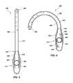
- FIG. 1shows a top view of a drainage device according to an embodiment of the present disclosure
- FIG. 2shows a side view of the drainage device of FIG. 1 ;
- FIG. 3shows a top cross-sectional view of the drainage device of FIG. 1 ;
- FIG. 4shows a top cross-sectional view of the drainage device of FIG. 1 in a bent position
- FIG. 5shows an enlarged top view of an activation apparatus according to an embodiment of the present disclosure
- FIG. 6shows a side cross-sectional view of the activation apparatus of FIG. 5 ;
- FIG. 7shows a schematic side view of a drainage device according to an embodiment of the present disclosure
- FIG. 8shows a side view of a drainage tube placement tool according to an embodiment of the present disclosure
- FIG. 9shows a detail view of the drainage tube placement tool of FIG. 8 disposed within a drainage tube
- FIG. 10shows a cross-sectional detail view of the drainage tube placement tool of FIG. 8 disposed within a drainage tube
- FIG. 11shows a side view of a drainage tube placement tool according to another embodiment of the present disclosure.
- FIG. 12shows a side view of a cleaning device for a drainage tube according to an embodiment of the present disclosure
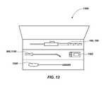
- FIG. 13shows a top view of a surgical kit including a drainage device and a drainage tube placement tool according to an embodiment of the present disclosure
- FIG. 14shows a cross-sectional view of a drainage device according to an embodiment of the present disclosure.
- distalrelates to an end of a device configured to be inserted into the body cavity of a patient
- proximalrelates to an end of a device configured to be outside of a patient
- a body cavity drainage devicein one embodiment, includes a body cavity drainage tube with a proximal end and a distal end.
- the proximal end of the body cavity drainage tubemay be connected to an activation apparatus including a rotatable control device and a compliant locking mechanism.
- Rotation of the rotatable control devicemay cause the distal end of the body cavity drainage tube to move relative to the proximal end of the drainage tube.
- the compliant locking mechanismIn an unlocked position, the compliant locking mechanism may allow rotation of the rotatable control device.
- the compliant locking mechanismIn a locked position, the compliant locking mechanism may substantially prevent rotation of the rotatable control device until a predetermined torque value is applied to the rotatable control device.
- a body cavity drainage devicein another embodiment, includes a body cavity drainage tube extending along a central axis between a proximal end and a distal end.
- a fluid outletmay be oriented substantially coaxially with the drainage tube.
- the proximal end of the body cavity drainage tubemay be attached to an activation apparatus.
- the activation apparatusmay include a rotatable control device for controlling a position of the distal end of the body cavity drainage tube.
- a packageincluding at least three of a body cavity drainage device, a drainage tube placement tool, a drainage tube cleaning device, and a visualization device may be provided to a user.
- FIG. 1shows a drainage device 100 according to an embodiment of the present disclosure.
- the drainage device 100may include a drainage tube 102 configured to provide drainage to a body cavity defined by or surrounded by soft tissue.
- the drainage device 100may be used to withdraw infection exudates from a pleural cavity by applying suction to the drainage tube 102 .
- positive pressuremay be applied to the drainage tube 102 , such as to introduce a fluid into the drainage tube 102 and/or body cavity, such as to dissolve material to be removed or to dislodge flow restrictions within the drainage tube 102 .
- the drainage device 100is described herein relative to use with pleural cavities, the present disclosure is not so limited. Accordingly, the drainage device 100 , elements thereof, and accompanying elements described in the present disclosure may be used for drainage from or introduction of fluids into other body cavities such as, by way of non-limiting example, veins, arteries, abdominal cavities, cranial cavities, etc.
- the drainage tube 102may include a proximal end 104 and a distal end 106 .
- the drainage tube 102may include at least one of an axial opening 108 in the distal end 106 and one or more lateral openings 110 proximate the distal end 106 into an open lumen of the drainage tube 102 .
- the drainage device 100may be configured to inhibit damage to the soft tissue surrounding the cavity while a portion of the drainage device 100 is inserted into the cavity or moved about within the cavity.
- the distal end 106 of the drainage device 100may include a substantially blunted geometry to prevent damage to the body cavity.
- the distal end 106may not have any sharp, pointed, or abrupt edges that, if present, could puncture or otherwise damage soft tissue of a body cavity.
- the drainage device 100may include any and all of the features and characteristics of the drainage devices described in U.S. patent application Ser. No. 13/840,986, filed Mar. 15, 2013 and published as US 2013/0211385, which is incorporated herein by reference for all that it discloses.
- the axial opening 108 and the one or more lateral openings 110may have an average diameter that is substantially the same size or smaller than an average inside diameter of the drainage tube 102 . Sizing the axial opening 108 and the one or more lateral openings in this manner relative to the inside diameter of the drainage tube 102 may ensure that any clots (e.g., blood clots) suctioned into the drainage tube 102 are sufficiently small to pass through the drainage tube 102 without obstructing (e.g., clogging) the drainage tube 102 .
- any clotse.g., blood clots
- the proximal end 104 of the drainage tube 102may be coupled to an activation apparatus 112 that may include a control device 114 .
- the control device 114may be, for example, a knob configured to be manually manipulated (e.g., rotated) by a user, such as a practitioner, physician, nurse, patient, or care provider.
- FIG. 2shows a side view of the drainage device 100 of FIG. 1 .
- the drainage device 100may include a fluid outlet 202 in fluid communication with the drainage tube 102 and may be configured for connection to a vacuum source for removal of material from a body cavity or to a source of one or more treatments to be introduced into the body cavity.
- the fluid outlet 202may be an integral extension of the drainage tube 102 .
- FIG. 3shows a cross-sectional view of the drainage device 100 of FIG. 1 .
- An activation apparatus 112may be attached at or near the proximal end 104 of the drainage tube 102 .
- the activation apparatus 112may include a pinion gear 302 , a first rack 304 , and a second rack 306 .
- the first and second racks 304 , 306may be complementary to and meshed with the pinion gear 302 .
- First and second flexible members 308 , 310may be attached to the first and second racks 304 and 306 , respectively.
- the first and second flexible members 308 , 310may have an elongate shape and may include, for example, metallic wires made from steel, titanium, nitinol, or other metals or alloys. Additionally or alternatively, the first and second flexible members 308 , 310 may include synthetic or natural fibers. As a further example, such wires or fibers may include a single strand or multiple strands of one or more materials bundled or woven together. The first and second flexible members 308 , 310 may be disposed within closed lumens within a wall 312 of the drainage tube 102 .
- the lumens through which the first and second flexible members 308 , 310 extendmay not be in fluid communication with the open lumen defined by the drainage tube 102 or with an exterior of the drainage tube 102 .
- the flexible members 308 , 310may be completely laterally enclosed within the wall 312 of the drainage tube 102 .
- the lumensmay be positioned within the wall of the drainage tube 102 such that each of the flexible members 308 , 310 is substantially directly opposite the other across a diameter of the drainage tube 102 .
- FIG. 4shows another cross-sectional view of the drainage device 100 of FIG. 1 .
- the pinion gear 302may rotate in response to an applied torque 402 .
- the torque 402may be applied by a user manually operating the control device 114 ( FIG. 1 ), which may be connected to the pinion gear 302 .
- Other embodimentsmay include an automated system configured to operate the control device 114 .
- Rotation of the pinion gear 302may cause generally linear movement of the first rack 304 in a first direction 404 and a corresponding generally linear movement of the second rack 306 in a second, opposite direction 406 .
- Movement of the first rack 304may create tension in the first flexible member 308 , which imparts a compressive force to a first side 408 of the drainage tube 102 .
- Movement of the second rack 306may allow slack in the second flexible member 310 .
- the compressive force from the first flexible member 308may cause the drainage tube 102 to contract along the first side 408 in which the first flexible member 308 is disposed and lengthen along a second side 410 in which the second flexible member 310 is disposed, causing the drainage tube 102 to assume an arcuate (e.g., bent) shape, such as the shape shown in FIG. 4 .
- the magnitude of the applied torque 402 and the corresponding refraction of the first flexible member 308may determine the extent of curvature imparted to the drainage tube 102 .
- Torquemay be applied in a direction opposite the direction indicated in FIG. 4 , resulting in curvature of the drainage tube 102 in an opposite direction to the curvature shown.
- the drainage device 100may be configured such that the distal end 106 may rotate at least about 360° from a first fully curved position (e.g., pointing down and to the left in the perspective shown in FIG. 4 ) to a second, opposite fully curved position (e.g., pointing down and to the right from the same perspective).
- the drainage device 100may include one or more optical fibers extending through lumens formed in the wall 312 of the drainage tube 102 and terminating at or near the distal end 106 .
- Such optical fibersmay be connected to a visualization device (e.g., a camera providing an image to an electronic display) to assist a user in placing or moving the drainage tube 102 within a patient's body cavity.
- the activation apparatus 112may include a compliant locking mechanism 500 .
- the compliant locking mechanism 500may have a locked position in which the compliant locking mechanism 500 maintains the control device 114 in a predetermined position selected by a user. The user may release (e.g., place the compliant locking mechanism 500 in an unlocked position) the compliant locking mechanism 500 to facilitate rotation of the control device 114 .
- the compliant locking mechanism 500may be configured to allow rotation of the control device 114 under a sufficiently high applied torque 402 ( FIG. 4 ) even when the compliant locking mechanism is in the locked position.
- the compliant locking mechanism 500may include a lock lever 502 with a proximal end 504 pivotably affixed to a main housing portion 506 of the activation apparatus 112 .
- the proximal end 504 of the lock lever 502may be resiliently (e.g., elastically) attached to the main housing portion 506 .
- the lock lever 502may be integrally molded with the main housing portion 506 (e.g., by an injection molding process).
- the lock lever 502may include a flexible structural portion (i.e., the resilient attachment of the proximal end 504 to the main housing portion 506 ) for rotating the lock lever 502 between the locked and unlocked positions.
- the lock lever 502may be attached to the main housing portion 506 with, e.g., a pinned hinge, and may be biased to a locked position by an elastic biasing element (e.g., a spring).
- a distal end 508 of the lock lever 502may include serrations (e.g., gear teeth) 510 configured to substantially mesh with gear teeth 512 of the pinion gear 302 .
- the serrations 510 of the distal end 508 of the lock lever 502may mesh with the gear teeth 512 of the pinion gear 302 and inhibit rotation of the pinion gear 302 when a torque is not applied (or an insufficient torque is applied) to the control device 114 , thereby fixing the control device 114 at a desired position.
- the usermay depress the lock lever 502 with a force 602 , as shown in FIG. 6 .
- the lock lever 502may pivot at the proximal end 504 , and the serrations 510 ( FIG. 5 ) of the distal end 508 may move downward (with reference to the orientation of FIG. 6 ) to clear (i.e., disengage from) the gear teeth 512 of the pinion gear 302 and facilitate rotation of the control device 114 and pinion gear 302 .
- the usermay then rotate the control device 114 to the desired position and release the lock lever 502 to maintain the control device 114 in the selected position.
- the usermay leave the lock lever 502 in the locked position, and apply torque to the control device 114 .
- the lock lever 502may elastically deform at one or more locations, e.g., at an angled juncture 604 .
- mechanical interaction between the serrations 510 ( FIG. 5 ) and the gear teeth 512may force the distal end 508 of the lock lever 502 in direction 606 , i.e., away from the pinion gear 302 .
- the lock lever 502may elastically deform enough to enable the serrations 510 ( FIG.
- the compliant lock mechanism 500may enable a user to adjust the position of the control device 114 without depressing the lock lever 502 , while maintaining the position of the control device 114 in the absence of a sufficiently high applied torque.
- the compliant lock mechanism 500may be configured such that it avoids or reduces movement of the control device 114 resulting from incidental contact when in the locked position, but allows movement at a threshold level of applied torque.
- a level of applied torquemay be, by way of example and not limitation, a torque value of greater than about 0.5 lb ⁇ ft (0.68 N ⁇ m), greater than about 1.0 lb ⁇ ft (1.36 N ⁇ m), or greater than about 5.0 lb ⁇ ft (6.8 N ⁇ m).
- a method of draining fluid from a body cavitymay include positioning a distal end of a tube of a body cavity drainage device at a first position within the body cavity. Fluid may be drained from the body cavity through the distal end of the tube of the body cavity drainage device while the distal end of the tube is in the first position.
- a usermay depress a locking lever to unlock a rotatable control device of the body cavity drainage device external to the body cavity.
- the usermay move the distal end of the tube of the body cavity drainage device to a second, different position within the body cavity.
- Moving the distal end of the tube of the body cavity drainage devicemay include rotating the rotatable control device of the body cavity drainage device, and the rotatable control device may be coupled to the distal end of the tube of the body cavity drainage device by flexible members.
- a drainage devicemay include a fluid outlet that is substantially aligned with the drainage tube.
- a drainage tube 702extends along a central axis A c , through an activation apparatus 704 , and to a fluid outlet 706 also aligned along the central axis A c .
- a single tube extending through the activation apparatus 704may form the drainage tube 702 and the fluid outlet 706 .
- the drainage device 700may comprise a unitary drainage tube 702 with a distal end 708 for insertion into a body cavity of a patient, a proximal end 710 including a fluid outlet 706 , and an activation apparatus 704 disposed on the drainage tube 702 between the proximal end 710 and the distal end 708 .
- the drainage tube 702 and the fluid outlet 706may be two separate tubes coupled (e.g., bonded, press-fit, glued) together.
- a control device 714may be disposed in a position offset from a central axis A c of the drainage tube 702 .
- At least one flexible member 718may extend from the control device 714 along an at least partially curvilinear (i.e., arcuate) path 720 .
- the at least one flexible member 718may be constrained to the curvilinear path 720 by guides 716 in the activation apparatus 704 and channels in the drainage tube 702 .
- the control device 714 , the at least one flexible member 718 , and the drainage tube 702may function in a similar manner to that described above in connection with FIGS. 3 and 4 .
- the activation apparatus 704may further include a compliant locking mechanism, as described above in connection with FIGS. 5 and 6 .
- the drainage tube placement tool 800may include a handle 802 affixed to a shaft 804 at a proximal end 806 .
- the shaft 804may be substantially straight, or may include a curved portion 810 near a distal end 808 , as shown in FIG. 8 .
- the shaft 804may have a substantially circular cross-sectional shape.
- the shaft 804may have a different cross-sectional shape, such as an elliptical shape, a rectilinear shape, or combinations thereof.
- the shaft 804may include a shoulder 812 (e.g., a step) where the cross-sectional shape of the shaft 804 varies from a first diameter 814 to a second, smaller diameter 816 .
- the shoulder 812may be disposed proximate the distal end 808 of the shaft 804 .
- the shoulder 812may be positioned within about one (1) inch (25.4 mm) or less of the distal end 808 of the shaft 804 .
- the shouldermay be disposed proximate the handle portion 802 , or the drainage tube placement tool 800 may not include a shoulder.
- a usermay insert the shaft 804 of the drainage tube placement tool 800 through a lateral opening 910 of a drainage tube 902 .
- the lateral opening 910may be similar to the lateral openings 110 described in connection with FIGS. 1 and 2 .
- the lateral opening 910may include features configured to facilitate insertion of the drainage tube placement tool 800 within the drainage tube 902 .
- a slit 912may extend from a periphery of the lateral opening 910 into a wall 914 of the drainage tube 902 .
- the slit 912may at least partially open, as shown in FIG. 9 , to ease passage of the drainage tube placement tool 800 through the drainage tube 902 .
- the slit 912may substantially close, and the diameter of the lateral opening 910 may be substantially similar to the diameter of other lateral openings 916 .
- Suction applied to the drainage tube 902 after removal of the drainage tube placement tool 800may also assist the slit 912 to close.
- the diameter of the lateral opening 910may be greater than the diameter of other lateral openings 110 .
- the drainage tube placement tool 800may be configured to stop at a predetermined insertion distance within the drainage tube 902 .
- the usermay continue to insert the drainage tube placement tool 800 within the drainage tube 902 until the shoulder 812 of the shaft 804 of the drainage tube placement tool 800 abuts a ferrule 1000 disposed near the distal end 106 of the drainage tube 902 and the shoulder 812 prevents further insertion of the placement tool 800 within the drainage tube 902 .
- the portion of the shaft 804 having the second diameter 816may enter an axial opening 1002 of the ferrule 1000 .
- the distal end 808 ( FIG. 8 ) of the drainage tube placement tool 800may be disposed proximate a distal end 1004 of the drainage tube 902 .
- the axial opening 1002 of the ferrule 1000may have a diameter smaller than an inside diameter of the drainage tube 102 .
- the shaft 804 of the drainage tube placement tool 800may have a length sufficient to extend through the lateral opening 910 of the body cavity drainage tube 902 , through a central lumen of the body cavity drainage tube 902 , and position the distal end 808 of the shaft 804 past the distal end 1004 of the drainage tube 902 .
- the distal end 808 of the shaft 804may protrude beyond the distal end 1004 of the drainage tube 902 .
- At least one of the flexible members 308 , 310 ( FIG. 3 ) or 718 ( FIG. 7 )may be attached to the ferrule 1000 .
- the ferrule 1000may be coupled to a control device (e.g., control device 114 ( FIG. 3 ) or control device 714 ( FIG. 7 )) of an activation apparatus (e.g., activation apparatus 112 ( FIG. 3 ) or activation apparatus 704 ( FIG. 7 )) through one or more flexible members 308 , 310 , and 718 .
- a control devicee.g., control device 114 ( FIG. 3 ) or control device 714 ( FIG. 7 )
- an activation apparatuse.g., activation apparatus 112 ( FIG. 3 ) or activation apparatus 704 ( FIG. 7 )
- the drainage tube placement tool 800may contribute additional stiffness (i.e., rigidity) to the drainage tube 902 to enable a user to insert the drainage tube 902 through an incision in a patient's body and into, e.g., the pleural cavity, without collapsing (e.g., kinking) the drainage tube 902 .
- the drainage tube placement tool 800may be made from a material having a greater modulus of elasticity (i.e., a greater stiffness) than the material of the drainage tube 902 .
- a usermay insert the distal end 812 of the drainage tube placement tool 800 into the drainage tube 902 , grasp the handle 802 , and insert the drainage tube 902 with the drainage tube placement tool 800 disposed therein through an incision and into the body cavity. The user may then remove the drainage tube placement tool 800 from the drainage tube 902 , leaving at least a portion of the drainage tube 902 disposed within the body cavity.
- the curved portion 810 of the drainage tube placement tool 800may be shaped to ease insertion of the drainage tube 902 with the drainage tube placement tool 800 disposed therein within a body cavity of a particular configuration.
- the curved portion 810 of the drainage tube placement tool 800may have a shape of a desired path the drainage tube 902 may follow as the drainage tube 902 is inserted into a body cavity.
- the curvemay facilitate directing the placement of the drainage tube 902 within the body cavity.
- the drainage tube placement tool 1100may include a shaft 1104 with a shoulder 1102 disposed near a proximal end 1106 of the shaft 1104 .
- a distal end 1108 of the shaft 1104may be inserted in a lateral opening 910 , 916 ( FIG. 9 ) of a drainage tube 902 .
- the shoulder 1102may abut a wall 914 ( FIG. 9 ) of the drainage tube 902 surrounding the lateral opening 910 , 916 at a predetermined insertion distance.
- the shoulder 1102may be absent, and a handle 1110 may abut against the lateral opening 910 , 916 to stop further insertion of the drainage tube placement tool 1100 into a drainage tube.
- the drainage tube placement tool 1100may be used with a drainage tube device that does or does not include a ferrule 1000 ( FIG. 10 ).
- the drainage tube placement tool 1100may be used with a drainage device according to the present disclosure, e.g., drainage devices 100 , 700 , or may be used with prior art drainage devices.
- the shaft 1104 of the drainage tube placement tool 1100may be substantially straight.
- the shaft 1104 of the drainage tube placement tool 1100may include a curved portion 810 like that shown in the embodiment of FIG. 8 .
- the shaft 804 , 1104 of the drainage tube placement tool 800 , 1100may be hollow (e.g., may include a channel therethrough) to accommodate a guide wire for aiding placement of the drainage tube within a body cavity and/or to accommodate one or more optical fibers therein.
- a guide wiremay be placed in a desired location through a hollow needle, and one or more dilators may be threaded over the guide wire to expand an incision made by the hollow needle through the skin and/or other tissue.
- the drainage tube placement tool 800 , 1100may be inserted into a drainage tube 100 , 700 as described above, and the guide wire may be threaded through the drainage tube placement tool 800 , 1100 .
- a distal end of the drainage tube 100 , 700may then be placed in the body cavity through the expanded incision using the guide wire.
- one or more optical fibersmay be inserted through the channel of the drainage tube placement tool 800 , 1100 .
- the one or more optical fibersmay be connected to a visualization device (e.g., a camera in communication with an electronic display) to assist the user in placing a drainage tube 100 , 700 within the body cavity.
- FIG. 12shows an embodiment of a cleaning device 1200 according to the present disclosure.
- the cleaning device 1200may include a handle 1202 , a shaft 1204 , and a cleaning instrument 1206 .
- the cleaning instrument 1206may be configured to be inserted through an fluid outlet 202 , 704 ( FIGS. 2 and 7 ) of the drainage device 100 , 700 .
- the cleaning instrument 1206may be inserted into the drainage device 100 , 700 while a portion of the drainage tube 102 remains disposed within a body cavity.
- the cleaning instrument 1206may be configured to retrieve solid matter, e.g., blood clots or other coagulations of physiological fluids, from the drainage tube 102 .
- a usermay remove a vacuum source from the fluid outlet 202 , 704 of the drainage device 100 , 700 .
- the usermay then insert the cleaning instrument 1206 into the fluid outlet 202 , 704 , grasp the handle 1202 , and feed the cleaning device 1200 into the drainage tube 102 until the cleaning instrument 1206 contacts the solid matter.
- the usermay remove the cleaning device 1200 and solid matter from the drainage tube 102 and reconnect the vacuum source to the fluid outlet 202 , 704 .
- the cleaning instrument 1206may comprise a coil of resilient material, such as a metal alloy or a polymer.
- the cleaning instrument 1206may have a helical shape, which may be rotated within the drainage tube 102 to force the solid matter out of the drainage tube 102 .
- a surgical kit 1300may include at least a drainage device 100 , 700 and a drainage tube placement tool 800 , 1100 .
- Each of the drainage device 100 , 700 and the drainage tube placement tool 800 , 1100 in the surgical kit 1300may be substantially as described above.
- the surgical kit 1300may also include one or more of a cleaning device 1200 for removal of obstructions in the drainage device 100 , 700 , a guide wire to facilitate placement of the drainage device 100 , 700 , at least one dilator for expanding an incision to facilitate placement of the drainage device 100 , 700 , and a visualization device 1302 to facilitate placement of the drainage device 100 , 700 .
- the visualization device 1302may include, for example, a fiber optic scope and/or a camera.
- the elements in the surgical kit 1300may provide complementary tools for a surgeon or other practitioner to use for draining a patient's body cavity. Each of the elements in the surgical kit 1300 or portions thereof may be sterilized and otherwise prepared for use in surgery. In addition, one or more of the elements in the surgical kit 1300 may be provided at least partially within a sterile envelope, protective covering, enclosure, or other container within the surgical kit 1300 for additional protection from contamination or damage.
- FIG. 14illustrates an embodiment of a drainage device 1400 including an activation apparatus 1412 and a detachable drainage tube 1402 .
- the activation apparatus 1412 and detachable drainage tube 1402may be configured to be detachably coupled together for positioning the detachable drainage tube 1402 in a body cavity (e.g., for initial insertion and/or for repositioning within the body cavity).
- the activation apparatus 1412 and detachable drainage tube 1402may be selectively detached from each other, such as to provide increased mobility to a patient.
- the detachable drainage tube 1402may include at least some similar features as the drainage tube 102 described above.
- the detachable drainage tube 1402may include a proximal end 1404 , a distal end 1406 , and one or more lateral openings 1410 proximate the distal end 1406 of the detachable drainage tube 1402 .
- the detachable drainage tube 1402may also include elongated flexible members 1408 extending from the proximal end 1404 to at or near the distal end 1406 of the detachable drainage tube 1402 , which may be disposed within lumens longitudinally extending through a sidewall of the detachable drainage tube 1402 .
- the activation apparatus 1412may include at least some similar features as the activation apparatus 112 described above.
- the activation apparatus 1412may include a control device 1414 , such as a knob or other element configured to be manually manipulated (e.g., rotated) by a user to remotely move the distal end 1406 of the detachable drainage tube 1402 when coupled thereto.
- the control device 1414may include a pinion configured to engage with first and second racks 1416 , 1418 .
- the proximal end 1404 of the detachable drainage tube 1402may be configured to couple the detachable drainage tube 1402 to the activation apparatus 1412 , and the activation apparatus 1412 may be configured to couple with the detachable drainage tube 1402 in a complementary fashion.
- a linking element 1420may be coupled to a proximal end of each of the elongated flexible members 1408 for operably connecting each of the elongated flexible members 1408 to a respective one of the first and second racks 1416 , 1418 .
- each linking element 1420may include a hook and each of the first and second racks 1416 , 1418 may include a complementary slot or hook 1421 .
- the hook of the linking element 1420may latch onto the complementary slot or hook 1421 of the respective one of the first and second racks 1416 , 1418 .
- the linking element 1420may include a notch (e.g., an annular notch) and each of the first and second racks 1416 , 1418 may include a complementary ridge or O-ring configured to deflect and snap into the notch of the linking element 1420 when the detachable drainage tube 1402 is operably connected to the activation apparatus 1412 .
- the activation apparatus 1412may include a suction tube 1422 that may be configured to form a fluid seal with a proximal end of the detachable drainage tube 1402 when the detachable drainage tube 1402 is operably connected to the activation apparatus 1412 . Accordingly, suction may be applied to the suction tube 1422 to draw fluids from a body cavity through the detachable drainage tube 1402 .
- the drainage device 1400may be used to withdraw fluids from a body cavity of a patient by inserting the distal end 1406 of the detachable drainage tube 1402 into the body cavity and, prior to or after insertion of the distal end 1406 of the detachable drainage tube 1402 , operably coupling the activation apparatus 1412 to the proximal end 1404 of the detachable drainage tube 1402 .
- a fluid sealmay be formed between the detachable drainage tube 1402 and the suction tube 1422 and the linking elements 1420 may be coupled to the first and second racks 1416 , 1418 .
- the activation apparatus 1412may be used to remotely position the distal end 1406 of the detachable drainage tube 1402 within the body cavity.
- the activation apparatus 1412may also be detached from the detachable drainage tube 1402 , such as to enable increased patient mobility.
- the linking elements 1420may be decoupled from the first and second racks 1416 , 1418 , and the detachable drainage tube 1402 may be decoupled from the suction tube 1422 .
- the proximal end of the detachable drainage tube 1402may be capped or plugged to inhibit fluid from inadvertently draining out of the detachable drainage tube 1402 .
- the surgical kit 1300may, in some embodiments, include the drainage device 1400 in a detached or an attached configuration.
- more than one detachable drainage tube 1406such as identical detachable drainage tubes 1406 or detachable drainage tubes 1406 of different lengths, diameters, materials, stiffnesses, etc., may be included in the surgical kit 1300 .
Landscapes
- Health & Medical Sciences (AREA)
- Life Sciences & Earth Sciences (AREA)
- Surgery (AREA)
- Engineering & Computer Science (AREA)
- Heart & Thoracic Surgery (AREA)
- Veterinary Medicine (AREA)
- Animal Behavior & Ethology (AREA)
- Public Health (AREA)
- Biomedical Technology (AREA)
- General Health & Medical Sciences (AREA)
- Biophysics (AREA)
- Nuclear Medicine, Radiotherapy & Molecular Imaging (AREA)
- Optics & Photonics (AREA)
- Physics & Mathematics (AREA)
- Medical Informatics (AREA)
- Molecular Biology (AREA)
- Radiology & Medical Imaging (AREA)
- Pathology (AREA)
- Anesthesiology (AREA)
- Hematology (AREA)
- Pulmonology (AREA)
- Mechanical Engineering (AREA)
- Vascular Medicine (AREA)
- Gynecology & Obstetrics (AREA)
- Oral & Maxillofacial Surgery (AREA)
- External Artificial Organs (AREA)
- Media Introduction/Drainage Providing Device (AREA)
Abstract
Description
Claims (18)
Priority Applications (3)
| Application Number | Priority Date | Filing Date | Title |
|---|---|---|---|
| US14/318,568US9821097B2 (en) | 2014-06-27 | 2014-06-27 | Body cavity drainage devices including drainage tubes having inline portions and related methods |
| PCT/US2015/038112WO2015200854A1 (en) | 2014-06-27 | 2015-06-26 | Body cavity drainage devices including drainage tubes having inline portions and related methods |
| US15/809,758US11058806B2 (en) | 2014-06-27 | 2017-11-10 | Body cavity drainage devices including drainage tubes having inline portions and related methods |
Applications Claiming Priority (1)
| Application Number | Priority Date | Filing Date | Title |
|---|---|---|---|
| US14/318,568US9821097B2 (en) | 2014-06-27 | 2014-06-27 | Body cavity drainage devices including drainage tubes having inline portions and related methods |
Related Child Applications (1)
| Application Number | Title | Priority Date | Filing Date |
|---|---|---|---|
| US15/809,758ContinuationUS11058806B2 (en) | 2014-06-27 | 2017-11-10 | Body cavity drainage devices including drainage tubes having inline portions and related methods |
Publications (2)
| Publication Number | Publication Date |
|---|---|
| US20150374890A1 US20150374890A1 (en) | 2015-12-31 |
| US9821097B2true US9821097B2 (en) | 2017-11-21 |
Family
ID=54929381
Family Applications (2)
| Application Number | Title | Priority Date | Filing Date |
|---|---|---|---|
| US14/318,568Active2035-05-11US9821097B2 (en) | 2014-06-27 | 2014-06-27 | Body cavity drainage devices including drainage tubes having inline portions and related methods |
| US15/809,758Active2035-07-02US11058806B2 (en) | 2014-06-27 | 2017-11-10 | Body cavity drainage devices including drainage tubes having inline portions and related methods |
Family Applications After (1)
| Application Number | Title | Priority Date | Filing Date |
|---|---|---|---|
| US15/809,758Active2035-07-02US11058806B2 (en) | 2014-06-27 | 2017-11-10 | Body cavity drainage devices including drainage tubes having inline portions and related methods |
Country Status (1)
| Country | Link |
|---|---|
| US (2) | US9821097B2 (en) |
Cited By (5)
| Publication number | Priority date | Publication date | Assignee | Title |
|---|---|---|---|---|
| US10029036B2 (en) | 2014-06-27 | 2018-07-24 | Merit Medical Systems, Inc. | Placement tools for body cavity drainage devices and related methods |
| US10232150B2 (en) | 2010-03-11 | 2019-03-19 | Merit Medical Systems, Inc. | Body cavity drainage devices and related methods |
| US10286183B2 (en) | 2015-11-25 | 2019-05-14 | Merit Medical Systems, Inc. | Steerable sheath catheter and methods of use |
| US11058806B2 (en) | 2014-06-27 | 2021-07-13 | The Seaberg Company, Inc. | Body cavity drainage devices including drainage tubes having inline portions and related methods |
| US11559662B2 (en) | 2018-04-13 | 2023-01-24 | Merit Medical Systems, Inc. | Steerable drainage devices |
Families Citing this family (3)
| Publication number | Priority date | Publication date | Assignee | Title |
|---|---|---|---|---|
| EP3057517B1 (en)* | 2013-10-15 | 2020-04-08 | Stryker Corporation | Device for creating a void space in a living tissue, the device including a handle with a control knob that can be set regardless of the orientation of the handle |
| US11849986B2 (en) | 2019-04-24 | 2023-12-26 | Stryker Corporation | Systems and methods for off-axis augmentation of a vertebral body |
| CN112156251B (en)* | 2020-10-31 | 2023-07-07 | 河南医学高等专科学校 | Anti-blocking effusion drainage device for cardiovascular department |
Citations (140)
| Publication number | Priority date | Publication date | Assignee | Title |
|---|---|---|---|---|
| US2393002A (en) | 1944-05-03 | 1946-01-15 | Smith Minton Larkin | Kidney catheter |
| US2898917A (en) | 1958-04-07 | 1959-08-11 | American Cystoscope Makers Inc | Surgical retaining device |
| US3225762A (en) | 1963-10-25 | 1965-12-28 | Yolan R Guttman | Intravenous stylet catheter |
| US3416532A (en) | 1964-07-24 | 1968-12-17 | Grossman Alan Richard | Drainage tube with means for scraping away debris therewithin |
| US3610231A (en)* | 1967-07-21 | 1971-10-05 | Olympus Optical Co | Endoscope |
| US3683929A (en) | 1970-12-28 | 1972-08-15 | Extracorporeal Med Spec | Device for draining cerebrospinal fluid in cases of hydrocephalus |
| US3830238A (en) | 1972-11-07 | 1974-08-20 | Deknatel Inc | Surgical drainage system with pressure measuring device |
| US3863641A (en) | 1972-09-29 | 1975-02-04 | Inst Pentru Creatie Stintific | Thoracic drainage catheter |
| US3937418A (en) | 1975-01-13 | 1976-02-10 | Lawrence Peska Associates, Inc. | Retractable dog leash |
| US3943929A (en) | 1974-11-15 | 1976-03-16 | The Kendall Company | Multi-chamber container and method |
| US4068383A (en) | 1975-10-09 | 1978-01-17 | Hoechstmass Balzer Gmbh & Co. | Tape measure reel |
| US4105031A (en) | 1975-10-10 | 1978-08-08 | Deknatel, Inc. | Attachable expansion chamber for pleural drainage device |
| US4202510A (en) | 1978-12-04 | 1980-05-13 | Stanish Walter F | Retractable pet leash |
| US4203430A (en) | 1976-12-16 | 1980-05-20 | Nagashige Takahashi | Device for controlling curvature of an end section in an endoscope |
| US4228802A (en) | 1977-06-15 | 1980-10-21 | Medical Products Institute Incorporated | Self-inflating and self-cleaning catheter assembly |
| US4439189A (en) | 1981-06-18 | 1984-03-27 | Bentley Laboratories, Inc. | Pleural drainage system |
| US4571239A (en) | 1982-03-01 | 1986-02-18 | Heyman Arnold M | Catheter-stylet assembly for slipover urethral instruments |
| US4580551A (en)* | 1984-11-02 | 1986-04-08 | Warner-Lambert Technologies, Inc. | Flexible plastic tube for endoscopes and the like |
| US4608982A (en) | 1984-03-07 | 1986-09-02 | Pollard Clifford W | Forceps |
| US4692154A (en) | 1986-06-02 | 1987-09-08 | Illinois Tool Works Inc. | Catheter guide |
| US4769019A (en) | 1987-02-13 | 1988-09-06 | Sherwood Medical Company | Drainage apparatus |
| US4862891A (en) | 1988-03-14 | 1989-09-05 | Canyon Medical Products | Device for sequential percutaneous dilation |
| US4883474A (en) | 1986-07-30 | 1989-11-28 | David S. Sheridan | Thoracic catheter |
| US4920980A (en) | 1987-09-14 | 1990-05-01 | Cordis Corporation | Catheter with controllable tip |
| US5026358A (en) | 1986-10-07 | 1991-06-25 | Pfizer Products Hospital Group Inc. | Drainage device |
| US5040543A (en) | 1990-07-25 | 1991-08-20 | C. R. Bard, Inc. | Movable core guidewire |
| US5047018A (en) | 1989-08-14 | 1991-09-10 | Minnesota Mining And Manufacturing Company | Catheter and stylet assembly having dual position stylet |
| US5108368A (en) | 1990-01-04 | 1992-04-28 | Pilot Cardiovascular System, Inc. | Steerable medical device |
| US5141503A (en) | 1991-01-29 | 1992-08-25 | Sewell Jr Frank K | Wound suction drainage system |
| US5157813A (en) | 1991-10-31 | 1992-10-27 | William Carroll | Shoelace tensioning device |
| US5205830A (en) | 1991-11-12 | 1993-04-27 | Arrow International Investment Corporation | Catheter assembly |
| US5207661A (en) | 1991-06-07 | 1993-05-04 | Smiths Industries Public Limited Company | Body fluid drainage assembly |
| WO1993025264A1 (en) | 1992-06-18 | 1993-12-23 | Nikomed Aps | A device for fixating a drainage tube, and a drainage tube assembly |
| US5297310A (en) | 1993-01-21 | 1994-03-29 | Dennis Cox | Cleaning brush for endoscopes |
| US5300050A (en) | 1986-10-07 | 1994-04-05 | Deknatel Technology Corporation | Drainage device |
| RU2012371C1 (en) | 1992-03-10 | 1994-05-15 | Анатолий Иванович Борисов | Catheter |
| US5312357A (en) | 1991-11-04 | 1994-05-17 | Drager Medical Electonic B.V. | Catheter |
| US5364351A (en)* | 1992-11-13 | 1994-11-15 | Ep Technologies, Inc. | Catheter steering mechanism |
| US5370610A (en) | 1993-02-09 | 1994-12-06 | Reynolds; James R. | Surgical drainage tube system |
| US5397321A (en) | 1993-07-30 | 1995-03-14 | Ep Technologies, Inc. | Variable curve electrophysiology catheter |
| US5409462A (en) | 1993-12-30 | 1995-04-25 | Cordis Corporation | Cyst puncture catheter assembly |
| US5409468A (en) | 1991-09-13 | 1995-04-25 | Sachse; Hans | Arrangement comprising a ureter tube, an auxiliary tube as well as a mandrin |
| US5540648A (en) | 1992-08-17 | 1996-07-30 | Yoon; Inbae | Medical instrument stabilizer with anchoring system and methods |
| US5601087A (en) | 1992-11-18 | 1997-02-11 | Spectrascience, Inc. | System for diagnosing tissue with guidewire |
| US5616131A (en) | 1992-09-23 | 1997-04-01 | Lasersurge, Inc. | Apparatus and method for anchoring surgical instrumentation |
| US5630795A (en) | 1991-08-02 | 1997-05-20 | Olympus Optical Co., Ltd. | Cleaning tube apparatus for endoscope |
| US5653696A (en) | 1984-05-14 | 1997-08-05 | Surgical Systems & Instruments, Inc. | Stent unclogging method |
| US5772670A (en) | 1995-10-18 | 1998-06-30 | Brosa; Ramon Bofill | Forceps for the surgical introduction of catheters and the like |
| US5807341A (en) | 1996-12-11 | 1998-09-15 | Team Medical Llc | Medical catheter dressing device |
| US5895400A (en) | 1997-06-27 | 1999-04-20 | Abela; George S. | Catheter with bristles |
| US5897534A (en) | 1996-08-29 | 1999-04-27 | Team Medical, Llc | Body fluids and solids drainage system |
| WO1999052481A1 (en) | 1998-04-16 | 1999-10-21 | Beth Israel Deaconess Medical Center | Catheter apparatus having an improved shape-memory alloy cuff and inflatable on-demand balloon for creating a bypass graft in vivo |
| US5987344A (en) | 1996-08-08 | 1999-11-16 | Medtronic, Inc. | Handle for catheter assembly with multifunction wire |
| US6045623A (en) | 1997-04-24 | 2000-04-04 | Cannon; Bradley Jay | Method and apparatus for cleaning catheter lumens |
| US6146355A (en)* | 1996-12-30 | 2000-11-14 | Myelotec, Inc. | Steerable catheter |
| US6171277B1 (en)* | 1997-12-01 | 2001-01-09 | Cordis Webster, Inc. | Bi-directional control handle for steerable catheter |
| US6183450B1 (en) | 1999-06-04 | 2001-02-06 | William A Lois | Catheter de-clogging device |
| US6193691B1 (en) | 1999-03-30 | 2001-02-27 | Depuy Orthopaedics, Inc. | Catheter system |
| US20010005785A1 (en) | 1999-12-22 | 2001-06-28 | Hans Sachse | Probe for the small intestines |
| US6254581B1 (en) | 1998-09-18 | 2001-07-03 | Creighton University | Pleural cavity drainage device |
| US20010007922A1 (en) | 1995-06-28 | 2001-07-12 | Schneider (Europe) Gmbh | Vascular pressure measuring device |
| US6468260B1 (en) | 1999-05-07 | 2002-10-22 | Biosense Webster, Inc. | Single gear drive bidirectional control handle for steerable catheter |
| US6500167B1 (en) | 1997-09-05 | 2002-12-31 | Biosense Webster, Inc. | Omni-directional steerable catheter |
| US6514273B1 (en) | 2000-03-22 | 2003-02-04 | Endovascular Technologies, Inc. | Device for removal of thrombus through physiological adhesion |
| US6530935B2 (en) | 1996-02-02 | 2003-03-11 | Regents Of The University Of California, The | Clot capture coil and method of using the same |
| US6530913B1 (en) | 1997-04-04 | 2003-03-11 | Jeffrey Giba | Steerable catheter |
| US6638253B2 (en) | 2001-07-17 | 2003-10-28 | Eugene Michael Breznock | Method and apparatus for chest drainage |
| US20030208252A1 (en) | 2001-05-14 | 2003-11-06 | O' Boyle Gary S. | Mri ablation catheter |
| US20030225364A1 (en) | 2002-06-04 | 2003-12-04 | Stanford, Office Of Technology Licensing | Device and method for rapid aspiration and collection of body tissue from within an enclosed body space |
| US20040035017A1 (en) | 2002-08-20 | 2004-02-26 | Ching-Chun Yang | Second brake of measuring tape |
| US20040116852A1 (en) | 2002-12-17 | 2004-06-17 | Scopton Paul M. | Rapid exchange dilation catheter for non-vascular applications |
| US6907992B2 (en) | 2002-02-28 | 2005-06-21 | Kimberly-Clark Worldwide, Inc. | Surgical kit for “push” type percutaneous endoscopic gastrostomy procedures |
| US20050184186A1 (en) | 2004-02-20 | 2005-08-25 | Chung Haap Tsoi | Retractable cable winder |
| US20050277875A1 (en)* | 2004-06-15 | 2005-12-15 | Selkee Thomas V | Steering mechanism for bi-directional catheter |
| US20060069311A1 (en)* | 2004-09-30 | 2006-03-30 | Roy Sullivan | Manually controlled endoscope |
| US7037290B2 (en) | 2002-12-16 | 2006-05-02 | Medtronic, Inc. | Multi-lumen steerable catheter |
| US20060142695A1 (en) | 2004-12-28 | 2006-06-29 | Knudson John C | Long travel steerable catheter actuator |
| US20060173449A1 (en)* | 2004-11-15 | 2006-08-03 | Shiva Sharareh | Catheter with microfabricated temperature sensing |
| US20060217667A1 (en)* | 2005-03-11 | 2006-09-28 | Accisano Nicholas G Iii | Drainage catheter hub with locking cam |
| US20060264925A1 (en)* | 2004-11-15 | 2006-11-23 | Shiva Sharareh | Catheter with multiple microfabricated temperature sensors |
| US20060264988A1 (en) | 2003-05-02 | 2006-11-23 | Metolius Biomedical, Llc | Body-space drainage-tube debris removal |
| US20060280773A1 (en) | 1999-08-05 | 2006-12-14 | Broncus Technologies, Inc. | Methods and devices for maintaining patency of surgically created channels in a body organ |
| US20070016133A1 (en) | 2005-07-05 | 2007-01-18 | Futurematrix Interventional, Inc. | Rapid exchange balloon dilation catheter having reinforced multi-lumen distal portion |
| US20070060997A1 (en) | 2005-09-15 | 2007-03-15 | Jan De Boer | Multi-lumen steerable catheter |
| US20070078455A1 (en) | 1997-06-20 | 2007-04-05 | Rassoll Rashidi | Electrophysiology/ablation catheter and remote actuator therefor |
| US20070156116A1 (en) | 2005-12-30 | 2007-07-05 | Gonzalez Pablo A | Dual-lever bi-directional handle |
| US20070167923A1 (en) | 2005-11-30 | 2007-07-19 | Wilson-Cook Medical Inc. D/B/A/ Cook Endoscopy | Short wire PEG and PEG-J tube |
| US20070287993A1 (en) | 2006-06-13 | 2007-12-13 | Hinman Cameron D | Tool with rotation lock |
| US20080021415A1 (en) | 2006-04-07 | 2008-01-24 | Anthony Durkin | Device suitable for connection to a substantially tubular element |
| US20080045921A1 (en) | 2003-11-25 | 2008-02-21 | Anderson Neil L | Modular Catheter |
| US20080097293A1 (en) | 2006-09-11 | 2008-04-24 | Boston Scientific Scimed, Inc. | Steerable catheter with rapid exchange lumen |
| US7407128B1 (en) | 2007-08-16 | 2008-08-05 | Hsi-Fan Chang | Cord reel box |
| US20080236209A1 (en) | 2007-03-28 | 2008-10-02 | Checkpoint Systems, Inc. | Cable wrap security device |
| US20090005771A1 (en)* | 2007-06-28 | 2009-01-01 | Chad Allen Lieber | Optical Pyrometric Catheter for Tissue Temperature Monitoring During Cardiac Ablation |
| US20090012365A1 (en) | 2005-07-22 | 2009-01-08 | Olympus Medical Systems Corp. | Endoscope |
| US7497854B2 (en) | 2004-05-07 | 2009-03-03 | Ethicon Endo-Surgery, Inc. | Method and instrument for effecting anastomosis of respective tissues defining two body lumens |
| US20090062769A1 (en) | 2007-04-13 | 2009-03-05 | Boston Scientific Scimed, Inc. | Rapid exchange catheter converter |
| US7578814B2 (en) | 2005-08-05 | 2009-08-25 | Merit Medical Systems, Inc. | Drainage catheter with lockable hub |
| US20090227900A1 (en) | 2008-03-10 | 2009-09-10 | Isaac Kim | Corewire design and construction for medical devices |
| US20090270800A1 (en)* | 2008-04-24 | 2009-10-29 | Medtronic Vascular, Inc. | Aspiration Catheter Having Selectively Deformable Tip |
| US20090270838A1 (en) | 2008-04-24 | 2009-10-29 | Medtronic Vascular, Inc. | Catheter Flushing Mandrel |
| US20090299327A1 (en) | 2008-06-02 | 2009-12-03 | Lorna Vista Medical, Inc. | Inflatable medical devices |
| US20100101061A1 (en) | 2005-06-27 | 2010-04-29 | Shin Kyung Inc. | Shoelace tightening device |
| US20100137775A1 (en) | 2008-11-25 | 2010-06-03 | Spiracur Inc. | Device for delivery of reduced pressure to body surfaces |
| US7740623B2 (en) | 2001-01-13 | 2010-06-22 | Medtronic, Inc. | Devices and methods for interstitial injection of biologic agents into tissue |
| US20100168731A1 (en) | 2008-12-31 | 2010-07-01 | Ardian, Inc. | Apparatus, systems, and methods for achieving intravascular, thermally-induced renal neuromodulation |
| US7758586B2 (en) | 2003-05-02 | 2010-07-20 | Atrium Medical Corporation | Method and apparatus for introducing catheters |
| US20100191057A1 (en) | 2008-07-28 | 2010-07-29 | Jansen Lex P | Penetrating member with direct visualization |
| US20100222664A1 (en) | 2008-08-22 | 2010-09-02 | C. R. Bard. Inc. | Catheter assembly including ecg sensor and magnetic assemblies |
| US20100249490A1 (en) | 2009-03-27 | 2010-09-30 | Circulite, Inc. | Transseptal cannula device, coaxial balloon delivery device, and methods of using the same |
| US20100249520A1 (en) | 2009-03-31 | 2010-09-30 | Shelton Iv Frederick E | Method Of Surgical Access |
| US20100264244A1 (en) | 2009-04-16 | 2010-10-21 | Cameron Nicholas Spencer | Flexible conduit storage device |
| US20110062268A1 (en) | 2009-09-17 | 2011-03-17 | Chi-Wen Cheng | Retractable cable device having protecting function |
| US20110077498A1 (en)* | 2009-09-29 | 2011-03-31 | Mcdaniel Benjamin D | Catheter with biased planar deflection |
| RU2415682C1 (en) | 2009-12-22 | 2011-04-10 | Государственное образовательное учреждение высшего профессионального образования "БАШКИРСКИЙ ГОСУДАРСТВЕННЫЙ МЕДИЦИНСКИЙ УНИВЕРСИТЕТ ФЕДЕРАЛЬНОГО АГЕНТСТВА ПО ЗДРАВООХРАНЕНИЮ И СОЦИАЛЬНОМУ РАЗВИТИЮ" | Draining device for pleural cavity |
| US20110213300A1 (en) | 2004-03-23 | 2011-09-01 | Boston Scientific Scimed, Inc. | In-vivo visualization system |
| US20110224647A1 (en) | 2010-03-11 | 2011-09-15 | Lazarus Harrison M | Body cavity drainage devices and related methods |
| US20110264089A1 (en)* | 2010-04-26 | 2011-10-27 | Michael Olen Zirkle | Irrigated catheter with internal position sensor |
| US20110282153A1 (en) | 2010-01-29 | 2011-11-17 | Olympus Medical Systems Corp. | Insertion instrument endoscope |
| US20120116161A1 (en)* | 2009-04-09 | 2012-05-10 | Nieman Timothy R | Optically guided medical tube and control unit assembly and methods of use |
| US20120157921A1 (en) | 2007-09-28 | 2012-06-21 | Codman & Shurtleff, Inc. | Catheter For Reduced Reflux in Targeted Tissue Delivery of a Therapeutic Agent |
| US20120172703A1 (en)* | 2010-12-30 | 2012-07-05 | Maribeth Esguerra | Catheter with single axial sensors |
| US8220460B2 (en) | 2004-11-19 | 2012-07-17 | Portaero, Inc. | Evacuation device and method for creating a localized pleurodesis |
| US8246752B2 (en) | 2008-01-25 | 2012-08-21 | Clear Catheter Systems, Inc. | Methods and devices to clear obstructions from medical tubes |
| US20130023840A1 (en) | 2009-09-30 | 2013-01-24 | Gunnar Loske | Vacuum Sponge Drainage |
| US20130046250A1 (en)* | 2009-12-02 | 2013-02-21 | Sanofi-Aventis Deutschland Gmbh | Drive Mechanism for Drug Delivery Devices |
| US8388759B2 (en) | 2008-01-25 | 2013-03-05 | Clear Catheter Systems, Inc. | Methods and devices to clear obstructions from medical tubes |
| US8409070B2 (en) | 2007-10-26 | 2013-04-02 | Xoft, Inc. | Brachytherapy apparatus and method for use with minimally invasive surgeries of the lung |
| US20130158379A1 (en)* | 2011-12-15 | 2013-06-20 | Thomas V. Selkee | Self-holding medical device control handle with cam actuated clutch mechanism |
| US20130204087A1 (en) | 2012-02-06 | 2013-08-08 | Cook Medical Technologies Llc | Body cavity access tube assembly and method of use |
| US20130211385A1 (en) | 2010-03-11 | 2013-08-15 | Harrison M. Lazarus | Body cavity drainage devices and related methods |
| US20130253505A1 (en)* | 2012-03-26 | 2013-09-26 | Jeffrey W. Schultz | Catheter with composite construction |
| US20130276718A1 (en) | 2012-04-19 | 2013-10-24 | Rollo Pet Company, Llc | Apparatus for retraction and extension of a leash or other flexible material |
| US20130310767A1 (en) | 2010-11-16 | 2013-11-21 | C2C Developement, LLC | Seal tip catheter devices or methods |
| US20140150782A1 (en) | 2012-12-04 | 2014-06-05 | Endoclear Llc | Closed suction cleaning devices, systems and methods |
| US20140193138A1 (en) | 2013-01-10 | 2014-07-10 | Ilan Koren | System and a method for constructing and for exchanging multimedia content |
| US20140290014A1 (en) | 2013-03-27 | 2014-10-02 | Danny Lee Myrick | Device for securely tying shoelaces and method of use |
| US20150148595A1 (en) | 2013-11-25 | 2015-05-28 | Avent, Inc. | Method of Placing a Drainage Catheter System |
| US20150374959A1 (en)* | 2014-06-27 | 2015-12-31 | Harrison M. Lazarus | Body cavity drainage devices with locking devices and related methods |
| US20150374889A1 (en)* | 2014-06-27 | 2015-12-31 | Harrison M. Lazarus | Surgical kits for body cavity drainage and related methods |
Family Cites Families (50)
| Publication number | Priority date | Publication date | Assignee | Title |
|---|---|---|---|---|
| US3867945A (en) | 1973-05-14 | 1975-02-25 | Wendell M Long | Catheter stylets |
| US5211644A (en) | 1991-09-20 | 1993-05-18 | Pmt Corporation | Process and apparatus for a dermal graft |
| US5571085A (en)* | 1995-03-24 | 1996-11-05 | Electro-Catheter Corporation | Steerable open lumen catheter |
| US6007531A (en)* | 1995-11-21 | 1999-12-28 | Catheter Imaging Systems, Inc. | Steerable catheter having disposable module and sterilizable handle and method of connecting same |
| AU2632001A (en)* | 2000-01-06 | 2001-07-16 | Raymond L. Bedell | Steerable fiberoptic epidural balloon catheter and scope |
| US20050131393A1 (en) | 2001-03-09 | 2005-06-16 | Scimed Life Systems, Inc. | Systems, methods and devices relating to delivery of medical implants |
| US6776765B2 (en) | 2001-08-21 | 2004-08-17 | Synovis Life Technologies, Inc. | Steerable stylet |
| US7306574B2 (en)* | 2002-01-17 | 2007-12-11 | Optivia Medical, Llc | Steerable dilatation system, dilator, and related methods for stepped dilatation |
| US7083595B2 (en) | 2002-05-01 | 2006-08-01 | Scimed Lipe Systems, Inc. | Medical catheter assembly and method of using the same |
| US20030236493A1 (en) | 2002-06-25 | 2003-12-25 | Medamicus, Inc. | Articulating handle for a deflectable catheter and method therefor |
| US7594903B2 (en)* | 2002-09-25 | 2009-09-29 | Abbott Cardiovascular Systems Inc. | Controlling shaft bending moment and whipping in a tendon deflection or other tendon system |
| USD669577S1 (en) | 2003-11-05 | 2012-10-23 | Kimberly-Clark Worldwide, Inc. | Cannula with band markings |
| US8052609B2 (en)* | 2005-04-15 | 2011-11-08 | Imacor Inc. | Connectorized probe with serial engagement mechanism |
| US8070685B2 (en)* | 2005-04-15 | 2011-12-06 | Imacor Inc. | Connectorized probe for transesophageal echocardiography |
| USD669168S1 (en) | 2005-11-18 | 2012-10-16 | Carefusion 2200, Inc. | Vertebral augmentation needle |
| EP2491870A1 (en)* | 2006-01-09 | 2012-08-29 | Cook Medical Technologies LLC | Deflectable tip access sheath |
| JP2009538189A (en) | 2006-05-22 | 2009-11-05 | オーソヴィータ・インコーポレーテッド | Delivery of multi-component compositions |
| US8057530B2 (en) | 2006-06-30 | 2011-11-15 | Tyco Healthcare Group Lp | Medical devices with amorphous metals, and methods therefor |
| GB2446124B (en) | 2007-02-02 | 2009-09-09 | Laerdal Medical As | Device for Monitoring Respiration |
| CA2677596C (en) | 2007-03-23 | 2014-12-16 | Invatec Technology Center Gmbh | Endoluminal prosthesis |
| JP5362708B2 (en) | 2007-05-31 | 2013-12-11 | ボストン サイエンティフィック リミテッド | Flexible endoscope |
| US8088163B1 (en) | 2008-02-06 | 2012-01-03 | Kleiner Jeffrey B | Tools and methods for spinal fusion |
| US8979744B2 (en) | 2008-09-08 | 2015-03-17 | Covidien Lp | Tunneling system |
| WO2010046874A2 (en) | 2008-10-24 | 2010-04-29 | Hospitech Respiration Ltd. | Method and system for ventilation |
| US9028509B2 (en) | 2008-12-05 | 2015-05-12 | Boston Scientific Scimed, Inc. | Insertion device for delivery of a mesh carrier |
| US8287532B2 (en)* | 2009-04-13 | 2012-10-16 | Biosense Webster, Inc. | Epicardial mapping and ablation catheter |
| US20100298642A1 (en)* | 2009-05-19 | 2010-11-25 | Ethicon Endo-Surgery, Inc. | Manipulatable guide system and methods for natural orifice translumenal endoscopic surgery |
| WO2010141837A1 (en)* | 2009-06-05 | 2010-12-09 | Vance Products Incorporated, D/B/A/ Cook Urological Incorporated | Access sheath and needle assembly for delivering therapeutic material |
| US8439970B2 (en)* | 2009-07-14 | 2013-05-14 | Edwards Lifesciences Corporation | Transapical delivery system for heart valves |
| US20110144576A1 (en)* | 2009-12-14 | 2011-06-16 | Voyage Medical, Inc. | Catheter orientation control system mechanisms |
| US8568417B2 (en)* | 2009-12-18 | 2013-10-29 | Charles River Engineering Solutions And Technologies, Llc | Articulating tool and methods of using |
| WO2011079620A1 (en) | 2009-12-31 | 2011-07-07 | Feng Qingliang | Device for puncturing body and introducing catheter |
| US8906013B2 (en) | 2010-04-09 | 2014-12-09 | Endosense Sa | Control handle for a contact force ablation catheter |
| US8702594B2 (en)* | 2010-10-21 | 2014-04-22 | Avram Allan Edidin | Imaging system having a quick connect coupling interface |
| US10058235B2 (en)* | 2011-03-01 | 2018-08-28 | Sanovas Intellectual Property, Llc | Steerable catheter |
| EP2793991B1 (en) | 2011-12-22 | 2019-02-06 | Boston Scientific Scimed, Inc. | Steerable sheath handle pulley mechanism |
| USD726304S1 (en) | 2012-03-22 | 2015-04-07 | Terumo Kabushiki Kaisha | Medicament sprayer |
| US9402604B2 (en)* | 2012-07-20 | 2016-08-02 | Covidien Lp | Apparatus for endoscopic procedures |
| USD732160S1 (en) | 2012-08-30 | 2015-06-16 | Terumo Kabushiki Kaisha | Intravenous catheter |
| USD718440S1 (en) | 2012-11-07 | 2014-11-25 | Karl Storz Gmbh & Co. Kg | Angled medical screwdriver |
| USD708741S1 (en) | 2012-11-08 | 2014-07-08 | Anchor Orthopedics Xt Inc | Handle for a medical device |
| USD724725S1 (en) | 2012-12-24 | 2015-03-17 | Hui-Yu Chang | Video stylet |
| US20170050017A1 (en) | 2013-02-25 | 2017-02-23 | Cosman Medical, Inc. | Electrosurgical System |
| USD710495S1 (en) | 2013-03-18 | 2014-08-05 | Mao-Tsun Wu | Peripherally inserted central catheter |
| US10398499B2 (en)* | 2013-05-24 | 2019-09-03 | Biosense Webster (Israel) Ltd. | Configurable control handle for catheters and other surgical tool |
| US9101356B1 (en)* | 2013-07-31 | 2015-08-11 | Christopher S. Jordan | Steerable suture instrument |
| USD728781S1 (en) | 2013-10-01 | 2015-05-05 | Dentsply International Inc. | Dental material dispenser tip |
| US9498602B2 (en) | 2014-05-20 | 2016-11-22 | Oscor Inc. | Guided intravascular catheter sheath having bi-directional steering assembly |
| US9821097B2 (en) | 2014-06-27 | 2017-11-21 | Merit Medical Systems, Inc. | Body cavity drainage devices including drainage tubes having inline portions and related methods |
| JP7074666B2 (en) | 2015-11-25 | 2022-05-24 | メリット・メディカル・システムズ・インコーポレイテッド | Maneuverable sheath catheter and how to use |
- 2014
- 2014-06-27USUS14/318,568patent/US9821097B2/enactiveActive
- 2017
- 2017-11-10USUS15/809,758patent/US11058806B2/enactiveActive
Patent Citations (142)
| Publication number | Priority date | Publication date | Assignee | Title |
|---|---|---|---|---|
| US2393002A (en) | 1944-05-03 | 1946-01-15 | Smith Minton Larkin | Kidney catheter |
| US2898917A (en) | 1958-04-07 | 1959-08-11 | American Cystoscope Makers Inc | Surgical retaining device |
| US3225762A (en) | 1963-10-25 | 1965-12-28 | Yolan R Guttman | Intravenous stylet catheter |
| US3416532A (en) | 1964-07-24 | 1968-12-17 | Grossman Alan Richard | Drainage tube with means for scraping away debris therewithin |
| US3610231A (en)* | 1967-07-21 | 1971-10-05 | Olympus Optical Co | Endoscope |
| US3683929A (en) | 1970-12-28 | 1972-08-15 | Extracorporeal Med Spec | Device for draining cerebrospinal fluid in cases of hydrocephalus |
| US3863641A (en) | 1972-09-29 | 1975-02-04 | Inst Pentru Creatie Stintific | Thoracic drainage catheter |
| US3830238A (en) | 1972-11-07 | 1974-08-20 | Deknatel Inc | Surgical drainage system with pressure measuring device |
| US3943929A (en) | 1974-11-15 | 1976-03-16 | The Kendall Company | Multi-chamber container and method |
| US3937418A (en) | 1975-01-13 | 1976-02-10 | Lawrence Peska Associates, Inc. | Retractable dog leash |
| US4068383A (en) | 1975-10-09 | 1978-01-17 | Hoechstmass Balzer Gmbh & Co. | Tape measure reel |
| US4105031A (en) | 1975-10-10 | 1978-08-08 | Deknatel, Inc. | Attachable expansion chamber for pleural drainage device |
| US4203430A (en) | 1976-12-16 | 1980-05-20 | Nagashige Takahashi | Device for controlling curvature of an end section in an endoscope |
| US4228802A (en) | 1977-06-15 | 1980-10-21 | Medical Products Institute Incorporated | Self-inflating and self-cleaning catheter assembly |
| US4202510A (en) | 1978-12-04 | 1980-05-13 | Stanish Walter F | Retractable pet leash |
| US4439189A (en) | 1981-06-18 | 1984-03-27 | Bentley Laboratories, Inc. | Pleural drainage system |
| US4571239A (en) | 1982-03-01 | 1986-02-18 | Heyman Arnold M | Catheter-stylet assembly for slipover urethral instruments |
| US4608982A (en) | 1984-03-07 | 1986-09-02 | Pollard Clifford W | Forceps |
| US5653696A (en) | 1984-05-14 | 1997-08-05 | Surgical Systems & Instruments, Inc. | Stent unclogging method |
| US4580551A (en)* | 1984-11-02 | 1986-04-08 | Warner-Lambert Technologies, Inc. | Flexible plastic tube for endoscopes and the like |
| US4692154A (en) | 1986-06-02 | 1987-09-08 | Illinois Tool Works Inc. | Catheter guide |
| US4883474A (en) | 1986-07-30 | 1989-11-28 | David S. Sheridan | Thoracic catheter |
| US5026358A (en) | 1986-10-07 | 1991-06-25 | Pfizer Products Hospital Group Inc. | Drainage device |
| US5300050A (en) | 1986-10-07 | 1994-04-05 | Deknatel Technology Corporation | Drainage device |
| US4769019A (en) | 1987-02-13 | 1988-09-06 | Sherwood Medical Company | Drainage apparatus |
| US4920980A (en) | 1987-09-14 | 1990-05-01 | Cordis Corporation | Catheter with controllable tip |
| US4862891A (en) | 1988-03-14 | 1989-09-05 | Canyon Medical Products | Device for sequential percutaneous dilation |
| US5047018A (en) | 1989-08-14 | 1991-09-10 | Minnesota Mining And Manufacturing Company | Catheter and stylet assembly having dual position stylet |
| US5108368A (en) | 1990-01-04 | 1992-04-28 | Pilot Cardiovascular System, Inc. | Steerable medical device |
| US5040543A (en) | 1990-07-25 | 1991-08-20 | C. R. Bard, Inc. | Movable core guidewire |
| US5141503A (en) | 1991-01-29 | 1992-08-25 | Sewell Jr Frank K | Wound suction drainage system |
| US5207661A (en) | 1991-06-07 | 1993-05-04 | Smiths Industries Public Limited Company | Body fluid drainage assembly |
| US5630795A (en) | 1991-08-02 | 1997-05-20 | Olympus Optical Co., Ltd. | Cleaning tube apparatus for endoscope |
| US5409468A (en) | 1991-09-13 | 1995-04-25 | Sachse; Hans | Arrangement comprising a ureter tube, an auxiliary tube as well as a mandrin |
| US5157813A (en) | 1991-10-31 | 1992-10-27 | William Carroll | Shoelace tensioning device |
| US5312357A (en) | 1991-11-04 | 1994-05-17 | Drager Medical Electonic B.V. | Catheter |
| US5205830A (en) | 1991-11-12 | 1993-04-27 | Arrow International Investment Corporation | Catheter assembly |
| RU2012371C1 (en) | 1992-03-10 | 1994-05-15 | Анатолий Иванович Борисов | Catheter |
| WO1993025264A1 (en) | 1992-06-18 | 1993-12-23 | Nikomed Aps | A device for fixating a drainage tube, and a drainage tube assembly |
| US5540648A (en) | 1992-08-17 | 1996-07-30 | Yoon; Inbae | Medical instrument stabilizer with anchoring system and methods |
| US5616131A (en) | 1992-09-23 | 1997-04-01 | Lasersurge, Inc. | Apparatus and method for anchoring surgical instrumentation |
| US5364351A (en)* | 1992-11-13 | 1994-11-15 | Ep Technologies, Inc. | Catheter steering mechanism |
| US5456664A (en) | 1992-11-13 | 1995-10-10 | Ep Technologies, Inc. | Catheter steering mechanism |
| US5601087A (en) | 1992-11-18 | 1997-02-11 | Spectrascience, Inc. | System for diagnosing tissue with guidewire |
| US5297310A (en) | 1993-01-21 | 1994-03-29 | Dennis Cox | Cleaning brush for endoscopes |
| US5370610A (en) | 1993-02-09 | 1994-12-06 | Reynolds; James R. | Surgical drainage tube system |
| US5397321A (en) | 1993-07-30 | 1995-03-14 | Ep Technologies, Inc. | Variable curve electrophysiology catheter |
| US5409462A (en) | 1993-12-30 | 1995-04-25 | Cordis Corporation | Cyst puncture catheter assembly |
| US20010007922A1 (en) | 1995-06-28 | 2001-07-12 | Schneider (Europe) Gmbh | Vascular pressure measuring device |
| US5772670A (en) | 1995-10-18 | 1998-06-30 | Brosa; Ramon Bofill | Forceps for the surgical introduction of catheters and the like |
| US6530935B2 (en) | 1996-02-02 | 2003-03-11 | Regents Of The University Of California, The | Clot capture coil and method of using the same |
| US5987344A (en) | 1996-08-08 | 1999-11-16 | Medtronic, Inc. | Handle for catheter assembly with multifunction wire |
| US5897534A (en) | 1996-08-29 | 1999-04-27 | Team Medical, Llc | Body fluids and solids drainage system |
| US5807341A (en) | 1996-12-11 | 1998-09-15 | Team Medical Llc | Medical catheter dressing device |
| US6146355A (en)* | 1996-12-30 | 2000-11-14 | Myelotec, Inc. | Steerable catheter |
| US6530913B1 (en) | 1997-04-04 | 2003-03-11 | Jeffrey Giba | Steerable catheter |
| US6045623A (en) | 1997-04-24 | 2000-04-04 | Cannon; Bradley Jay | Method and apparatus for cleaning catheter lumens |
| US20070078455A1 (en) | 1997-06-20 | 2007-04-05 | Rassoll Rashidi | Electrophysiology/ablation catheter and remote actuator therefor |
| US5895400A (en) | 1997-06-27 | 1999-04-20 | Abela; George S. | Catheter with bristles |
| US6500167B1 (en) | 1997-09-05 | 2002-12-31 | Biosense Webster, Inc. | Omni-directional steerable catheter |
| US6171277B1 (en)* | 1997-12-01 | 2001-01-09 | Cordis Webster, Inc. | Bi-directional control handle for steerable catheter |
| WO1999052481A1 (en) | 1998-04-16 | 1999-10-21 | Beth Israel Deaconess Medical Center | Catheter apparatus having an improved shape-memory alloy cuff and inflatable on-demand balloon for creating a bypass graft in vivo |
| US6254581B1 (en) | 1998-09-18 | 2001-07-03 | Creighton University | Pleural cavity drainage device |
| US6193691B1 (en) | 1999-03-30 | 2001-02-27 | Depuy Orthopaedics, Inc. | Catheter system |
| US6468260B1 (en) | 1999-05-07 | 2002-10-22 | Biosense Webster, Inc. | Single gear drive bidirectional control handle for steerable catheter |
| US6183450B1 (en) | 1999-06-04 | 2001-02-06 | William A Lois | Catheter de-clogging device |
| US20060280773A1 (en) | 1999-08-05 | 2006-12-14 | Broncus Technologies, Inc. | Methods and devices for maintaining patency of surgically created channels in a body organ |
| US20010005785A1 (en) | 1999-12-22 | 2001-06-28 | Hans Sachse | Probe for the small intestines |
| US6514273B1 (en) | 2000-03-22 | 2003-02-04 | Endovascular Technologies, Inc. | Device for removal of thrombus through physiological adhesion |
| US7740623B2 (en) | 2001-01-13 | 2010-06-22 | Medtronic, Inc. | Devices and methods for interstitial injection of biologic agents into tissue |
| US20030208252A1 (en) | 2001-05-14 | 2003-11-06 | O' Boyle Gary S. | Mri ablation catheter |
| US6638253B2 (en) | 2001-07-17 | 2003-10-28 | Eugene Michael Breznock | Method and apparatus for chest drainage |
| US6907992B2 (en) | 2002-02-28 | 2005-06-21 | Kimberly-Clark Worldwide, Inc. | Surgical kit for “push” type percutaneous endoscopic gastrostomy procedures |
| US20030225364A1 (en) | 2002-06-04 | 2003-12-04 | Stanford, Office Of Technology Licensing | Device and method for rapid aspiration and collection of body tissue from within an enclosed body space |
| US20040035017A1 (en) | 2002-08-20 | 2004-02-26 | Ching-Chun Yang | Second brake of measuring tape |
| US7037290B2 (en) | 2002-12-16 | 2006-05-02 | Medtronic, Inc. | Multi-lumen steerable catheter |
| US20040116852A1 (en) | 2002-12-17 | 2004-06-17 | Scopton Paul M. | Rapid exchange dilation catheter for non-vascular applications |
| US7758586B2 (en) | 2003-05-02 | 2010-07-20 | Atrium Medical Corporation | Method and apparatus for introducing catheters |
| US20110040285A1 (en) | 2003-05-02 | 2011-02-17 | Medical Device Innovations, LLC | Body-space drainage-tube debris removal |
| US20060264988A1 (en) | 2003-05-02 | 2006-11-23 | Metolius Biomedical, Llc | Body-space drainage-tube debris removal |
| US20080045921A1 (en) | 2003-11-25 | 2008-02-21 | Anderson Neil L | Modular Catheter |
| US20050184186A1 (en) | 2004-02-20 | 2005-08-25 | Chung Haap Tsoi | Retractable cable winder |
| US20110213300A1 (en) | 2004-03-23 | 2011-09-01 | Boston Scientific Scimed, Inc. | In-vivo visualization system |
| US7497854B2 (en) | 2004-05-07 | 2009-03-03 | Ethicon Endo-Surgery, Inc. | Method and instrument for effecting anastomosis of respective tissues defining two body lumens |
| US20050277875A1 (en)* | 2004-06-15 | 2005-12-15 | Selkee Thomas V | Steering mechanism for bi-directional catheter |
| US20060069311A1 (en)* | 2004-09-30 | 2006-03-30 | Roy Sullivan | Manually controlled endoscope |
| US20060264925A1 (en)* | 2004-11-15 | 2006-11-23 | Shiva Sharareh | Catheter with multiple microfabricated temperature sensors |
| US20060173449A1 (en)* | 2004-11-15 | 2006-08-03 | Shiva Sharareh | Catheter with microfabricated temperature sensing |
| US8220460B2 (en) | 2004-11-19 | 2012-07-17 | Portaero, Inc. | Evacuation device and method for creating a localized pleurodesis |
| US20060142695A1 (en) | 2004-12-28 | 2006-06-29 | Knudson John C | Long travel steerable catheter actuator |
| US20060217667A1 (en)* | 2005-03-11 | 2006-09-28 | Accisano Nicholas G Iii | Drainage catheter hub with locking cam |
| US20100101061A1 (en) | 2005-06-27 | 2010-04-29 | Shin Kyung Inc. | Shoelace tightening device |
| US20070016133A1 (en) | 2005-07-05 | 2007-01-18 | Futurematrix Interventional, Inc. | Rapid exchange balloon dilation catheter having reinforced multi-lumen distal portion |
| US20090012365A1 (en) | 2005-07-22 | 2009-01-08 | Olympus Medical Systems Corp. | Endoscope |
| US7578814B2 (en) | 2005-08-05 | 2009-08-25 | Merit Medical Systems, Inc. | Drainage catheter with lockable hub |
| US20070060997A1 (en) | 2005-09-15 | 2007-03-15 | Jan De Boer | Multi-lumen steerable catheter |
| US20070167923A1 (en) | 2005-11-30 | 2007-07-19 | Wilson-Cook Medical Inc. D/B/A/ Cook Endoscopy | Short wire PEG and PEG-J tube |
| US20070156116A1 (en) | 2005-12-30 | 2007-07-05 | Gonzalez Pablo A | Dual-lever bi-directional handle |
| US20080021415A1 (en) | 2006-04-07 | 2008-01-24 | Anthony Durkin | Device suitable for connection to a substantially tubular element |
| US20070287993A1 (en) | 2006-06-13 | 2007-12-13 | Hinman Cameron D | Tool with rotation lock |
| US20080097293A1 (en) | 2006-09-11 | 2008-04-24 | Boston Scientific Scimed, Inc. | Steerable catheter with rapid exchange lumen |
| US20080236209A1 (en) | 2007-03-28 | 2008-10-02 | Checkpoint Systems, Inc. | Cable wrap security device |
| US20090062769A1 (en) | 2007-04-13 | 2009-03-05 | Boston Scientific Scimed, Inc. | Rapid exchange catheter converter |
| US20090005771A1 (en)* | 2007-06-28 | 2009-01-01 | Chad Allen Lieber | Optical Pyrometric Catheter for Tissue Temperature Monitoring During Cardiac Ablation |
| US7407128B1 (en) | 2007-08-16 | 2008-08-05 | Hsi-Fan Chang | Cord reel box |
| US20120157921A1 (en) | 2007-09-28 | 2012-06-21 | Codman & Shurtleff, Inc. | Catheter For Reduced Reflux in Targeted Tissue Delivery of a Therapeutic Agent |
| US8409070B2 (en) | 2007-10-26 | 2013-04-02 | Xoft, Inc. | Brachytherapy apparatus and method for use with minimally invasive surgeries of the lung |
| US8246752B2 (en) | 2008-01-25 | 2012-08-21 | Clear Catheter Systems, Inc. | Methods and devices to clear obstructions from medical tubes |
| US8388759B2 (en) | 2008-01-25 | 2013-03-05 | Clear Catheter Systems, Inc. | Methods and devices to clear obstructions from medical tubes |
| US20090227900A1 (en) | 2008-03-10 | 2009-09-10 | Isaac Kim | Corewire design and construction for medical devices |
| US20090270838A1 (en) | 2008-04-24 | 2009-10-29 | Medtronic Vascular, Inc. | Catheter Flushing Mandrel |
| US20090270800A1 (en)* | 2008-04-24 | 2009-10-29 | Medtronic Vascular, Inc. | Aspiration Catheter Having Selectively Deformable Tip |
| US20090299327A1 (en) | 2008-06-02 | 2009-12-03 | Lorna Vista Medical, Inc. | Inflatable medical devices |
| US20100191057A1 (en) | 2008-07-28 | 2010-07-29 | Jansen Lex P | Penetrating member with direct visualization |
| US20100222664A1 (en) | 2008-08-22 | 2010-09-02 | C. R. Bard. Inc. | Catheter assembly including ecg sensor and magnetic assemblies |
| US20100137775A1 (en) | 2008-11-25 | 2010-06-03 | Spiracur Inc. | Device for delivery of reduced pressure to body surfaces |
| US20100168731A1 (en) | 2008-12-31 | 2010-07-01 | Ardian, Inc. | Apparatus, systems, and methods for achieving intravascular, thermally-induced renal neuromodulation |
| US20100249490A1 (en) | 2009-03-27 | 2010-09-30 | Circulite, Inc. | Transseptal cannula device, coaxial balloon delivery device, and methods of using the same |
| US20100249520A1 (en) | 2009-03-31 | 2010-09-30 | Shelton Iv Frederick E | Method Of Surgical Access |
| US20120116161A1 (en)* | 2009-04-09 | 2012-05-10 | Nieman Timothy R | Optically guided medical tube and control unit assembly and methods of use |
| US20100264244A1 (en) | 2009-04-16 | 2010-10-21 | Cameron Nicholas Spencer | Flexible conduit storage device |
| US20110062268A1 (en) | 2009-09-17 | 2011-03-17 | Chi-Wen Cheng | Retractable cable device having protecting function |
| US20110077498A1 (en)* | 2009-09-29 | 2011-03-31 | Mcdaniel Benjamin D | Catheter with biased planar deflection |
| US20130023840A1 (en) | 2009-09-30 | 2013-01-24 | Gunnar Loske | Vacuum Sponge Drainage |
| US20130046250A1 (en)* | 2009-12-02 | 2013-02-21 | Sanofi-Aventis Deutschland Gmbh | Drive Mechanism for Drug Delivery Devices |
| RU2415682C1 (en) | 2009-12-22 | 2011-04-10 | Государственное образовательное учреждение высшего профессионального образования "БАШКИРСКИЙ ГОСУДАРСТВЕННЫЙ МЕДИЦИНСКИЙ УНИВЕРСИТЕТ ФЕДЕРАЛЬНОГО АГЕНТСТВА ПО ЗДРАВООХРАНЕНИЮ И СОЦИАЛЬНОМУ РАЗВИТИЮ" | Draining device for pleural cavity |
| US20110282153A1 (en) | 2010-01-29 | 2011-11-17 | Olympus Medical Systems Corp. | Insertion instrument endoscope |
| US20130211385A1 (en) | 2010-03-11 | 2013-08-15 | Harrison M. Lazarus | Body cavity drainage devices and related methods |
| US20110224647A1 (en) | 2010-03-11 | 2011-09-15 | Lazarus Harrison M | Body cavity drainage devices and related methods |
| US20110264089A1 (en)* | 2010-04-26 | 2011-10-27 | Michael Olen Zirkle | Irrigated catheter with internal position sensor |
| US20130310767A1 (en) | 2010-11-16 | 2013-11-21 | C2C Developement, LLC | Seal tip catheter devices or methods |
| US20120172703A1 (en)* | 2010-12-30 | 2012-07-05 | Maribeth Esguerra | Catheter with single axial sensors |
| US20130158379A1 (en)* | 2011-12-15 | 2013-06-20 | Thomas V. Selkee | Self-holding medical device control handle with cam actuated clutch mechanism |
| US20130204087A1 (en) | 2012-02-06 | 2013-08-08 | Cook Medical Technologies Llc | Body cavity access tube assembly and method of use |
| US20130253505A1 (en)* | 2012-03-26 | 2013-09-26 | Jeffrey W. Schultz | Catheter with composite construction |
| US20130276718A1 (en) | 2012-04-19 | 2013-10-24 | Rollo Pet Company, Llc | Apparatus for retraction and extension of a leash or other flexible material |
| US20140150782A1 (en) | 2012-12-04 | 2014-06-05 | Endoclear Llc | Closed suction cleaning devices, systems and methods |
| US20140193138A1 (en) | 2013-01-10 | 2014-07-10 | Ilan Koren | System and a method for constructing and for exchanging multimedia content |
| US20140290014A1 (en) | 2013-03-27 | 2014-10-02 | Danny Lee Myrick | Device for securely tying shoelaces and method of use |
| US20150148595A1 (en) | 2013-11-25 | 2015-05-28 | Avent, Inc. | Method of Placing a Drainage Catheter System |
| US20150374959A1 (en)* | 2014-06-27 | 2015-12-31 | Harrison M. Lazarus | Body cavity drainage devices with locking devices and related methods |
| US20150374889A1 (en)* | 2014-06-27 | 2015-12-31 | Harrison M. Lazarus | Surgical kits for body cavity drainage and related methods |
Non-Patent Citations (6)
| Title |
|---|
| "Catheter prevents clogging," Research & Development, <<http://www.rdmag.com/printpdf/award-winners/2011/08/catheter-prevents-clogging, Aug. 14, 2011>>, 3 pages. |
| "Express Dry Seal Chest Drain, Instructions for Use," Atrium, www.atriummed.com (2003) 2 pages. |
| "Medical pleuroscopy", <http://www.cancercenter.com/treatments/medical-pleuroscopy/>, Cancer Treatment Centers of America, retrieved Aug. 19, 2013, 2 Pages. |
| "Rocket® Cardiothoracic Range," Rocketmedical, Issue 1, R89947, Jan. 2011, 23 pages. |
| Ben-Isaac et al., "Flexible Fiberoptic Pleuroscopy: Pleural and Lung Biopsy*," Experimental Approaches, Chest Journal No. 67, <http://journal.publications.chestnet.org/data/Journals/CHEST/20966/573.pdf>, May 5, 1975, pp. 573-576. |
| International Preliminary Report on Patentability with Written Opinion for International Application No. PCT/US2015/038112, dated Dec. 27, 2016, 5 pages. |
Cited By (5)
| Publication number | Priority date | Publication date | Assignee | Title |
|---|---|---|---|---|
| US10232150B2 (en) | 2010-03-11 | 2019-03-19 | Merit Medical Systems, Inc. | Body cavity drainage devices and related methods |
| US10029036B2 (en) | 2014-06-27 | 2018-07-24 | Merit Medical Systems, Inc. | Placement tools for body cavity drainage devices and related methods |
| US11058806B2 (en) | 2014-06-27 | 2021-07-13 | The Seaberg Company, Inc. | Body cavity drainage devices including drainage tubes having inline portions and related methods |
| US10286183B2 (en) | 2015-11-25 | 2019-05-14 | Merit Medical Systems, Inc. | Steerable sheath catheter and methods of use |
| US11559662B2 (en) | 2018-04-13 | 2023-01-24 | Merit Medical Systems, Inc. | Steerable drainage devices |
Also Published As
| Publication number | Publication date |
|---|---|
| US11058806B2 (en) | 2021-07-13 |
| US20150374890A1 (en) | 2015-12-31 |
| US20180085504A1 (en) | 2018-03-29 |
Similar Documents
| Publication | Publication Date | Title |
|---|---|---|
| US9649415B2 (en) | Surgical kits for body cavity drainage and related methods | |
| US9604033B2 (en) | Body cavity drainage devices with locking devices and related methods | |
| US11058806B2 (en) | Body cavity drainage devices including drainage tubes having inline portions and related methods | |
| US11534190B2 (en) | Medical systems, devices, and related methods | |
| US11395579B2 (en) | Portable endoscope with disposable steerable cannula | |
| US20200281772A1 (en) | Insertion system for deploying a ventilation device | |
| US9775674B2 (en) | Suction lithotripsy apparatus, method and kit | |
| US7815045B2 (en) | Mid-stream flushing adapter assembly | |
| EP3189798B1 (en) | Endoscopic treatment instrument, treatment instrument unit, and treatment system | |
| EP3200673B1 (en) | Ureteroscope and attachment device therefor | |
| JP2006522657A (en) | Ureteral access sheath | |
| KR20170058403A (en) | Balloon catheter assembly | |
| EP3216380A1 (en) | Assist tool and endoscope system | |
| WO2015200854A1 (en) | Body cavity drainage devices including drainage tubes having inline portions and related methods | |
| US10029036B2 (en) | Placement tools for body cavity drainage devices and related methods | |
| US10537361B2 (en) | Access device having a fluid pathway and methods of using the same | |
| JP2009232949A (en) | Guiding catheter |
Legal Events
| Date | Code | Title | Description |
|---|---|---|---|
| AS | Assignment | Owner name:LAZARUS MEDICAL TECHNOLOGIES, LLC, UTAH Free format text:ASSIGNMENT OF ASSIGNORS INTEREST;ASSIGNOR:LAZARUS, HARRISON, M.D.;REEL/FRAME:042460/0368 Effective date:20170522 | |
| AS | Assignment | Owner name:MERIT MEDICAL SYSTEMS, INC., UTAH Free format text:ASSIGNMENT OF ASSIGNORS INTEREST;ASSIGNOR:LAZARUS MEDICAL TECHNOLOGIES, LLC;REEL/FRAME:042812/0572 Effective date:20170616 | |
| AS | Assignment | Owner name:WELLS FARGO BANK, NATIONAL ASSOCIATION, AS ADMINISTRATIVE AGENT, NORTH CAROLINA Free format text:SECURITY INTEREST;ASSIGNOR:MERIT MEDICAL SYSTEMS, INC.;REEL/FRAME:043706/0746 Effective date:20170915 Owner name:WELLS FARGO BANK, NATIONAL ASSOCIATION, AS ADMINIS Free format text:SECURITY INTEREST;ASSIGNOR:MERIT MEDICAL SYSTEMS, INC.;REEL/FRAME:043706/0746 Effective date:20170915 | |
| FEPP | Fee payment procedure | Free format text:ENTITY STATUS SET TO UNDISCOUNTED (ORIGINAL EVENT CODE: BIG.) | |
| STCF | Information on status: patent grant | Free format text:PATENTED CASE | |
| CC | Certificate of correction | ||
| AS | Assignment | Owner name:LAZARUS MEDICAL TECHNOLOGIES, LLC, UTAH Free format text:ASSIGNMENT OF ASSIGNORS INTEREST;ASSIGNOR:MERIT MEDICAL SYSTEMS, INC.;REEL/FRAME:051237/0092 Effective date:20190524 | |
| AS | Assignment | Owner name:THE SEABERG COMPANY, INC., DBA SAM MEDICAL, OREGON Free format text:LICENSE;ASSIGNOR:LAZARUS MEDICAL TECHNOLOGIES, LLC;REEL/FRAME:052434/0956 Effective date:20200118 | |
| AS | Assignment | Owner name:THE SEABERG COMPANY, INC., DBA SAM MEDICAL, OREGON Free format text:LICENSE;ASSIGNOR:LAZARUS MEDICAL TECHNOLOGIES, LLC;REEL/FRAME:054101/0905 Effective date:20201012 | |
| MAFP | Maintenance fee payment | Free format text:PAYMENT OF MAINTENANCE FEE, 4TH YEAR, LARGE ENTITY (ORIGINAL EVENT CODE: M1551); ENTITY STATUS OF PATENT OWNER: LARGE ENTITY Year of fee payment:4 | |
| FEPP | Fee payment procedure | Free format text:ENTITY STATUS SET TO SMALL (ORIGINAL EVENT CODE: SMAL); ENTITY STATUS OF PATENT OWNER: SMALL ENTITY | |
| MAFP | Maintenance fee payment | Free format text:PAYMENT OF MAINTENANCE FEE, 8TH YR, SMALL ENTITY (ORIGINAL EVENT CODE: M2552); ENTITY STATUS OF PATENT OWNER: SMALL ENTITY Year of fee payment:8 |