US9820858B2 - Knee implants and instruments - Google Patents
Knee implants and instrumentsDownload PDFInfo
- Publication number
- US9820858B2 US9820858B2US14/665,511US201514665511AUS9820858B2US 9820858 B2US9820858 B2US 9820858B2US 201514665511 AUS201514665511 AUS 201514665511AUS 9820858 B2US9820858 B2US 9820858B2
- Authority
- US
- United States
- Prior art keywords
- cut block
- fin
- posterior
- tibial tray
- pin
- Prior art date
- Legal status (The legal status is an assumption and is not a legal conclusion. Google has not performed a legal analysis and makes no representation as to the accuracy of the status listed.)
- Expired - Fee Related
Links
Images


Classifications
- A—HUMAN NECESSITIES
- A61—MEDICAL OR VETERINARY SCIENCE; HYGIENE
- A61F—FILTERS IMPLANTABLE INTO BLOOD VESSELS; PROSTHESES; DEVICES PROVIDING PATENCY TO, OR PREVENTING COLLAPSING OF, TUBULAR STRUCTURES OF THE BODY, e.g. STENTS; ORTHOPAEDIC, NURSING OR CONTRACEPTIVE DEVICES; FOMENTATION; TREATMENT OR PROTECTION OF EYES OR EARS; BANDAGES, DRESSINGS OR ABSORBENT PADS; FIRST-AID KITS
- A61F2/00—Filters implantable into blood vessels; Prostheses, i.e. artificial substitutes or replacements for parts of the body; Appliances for connecting them with the body; Devices providing patency to, or preventing collapsing of, tubular structures of the body, e.g. stents
- A61F2/02—Prostheses implantable into the body
- A61F2/30—Joints
- A61F2/38—Joints for elbows or knees
- A61F2/389—Tibial components
- A—HUMAN NECESSITIES
- A61—MEDICAL OR VETERINARY SCIENCE; HYGIENE
- A61B—DIAGNOSIS; SURGERY; IDENTIFICATION
- A61B17/00—Surgical instruments, devices or methods
- A61B17/14—Surgical saws
- A61B17/15—Guides therefor
- A61B17/154—Guides therefor for preparing bone for knee prosthesis
- A61B17/155—Cutting femur
- A—HUMAN NECESSITIES
- A61—MEDICAL OR VETERINARY SCIENCE; HYGIENE
- A61F—FILTERS IMPLANTABLE INTO BLOOD VESSELS; PROSTHESES; DEVICES PROVIDING PATENCY TO, OR PREVENTING COLLAPSING OF, TUBULAR STRUCTURES OF THE BODY, e.g. STENTS; ORTHOPAEDIC, NURSING OR CONTRACEPTIVE DEVICES; FOMENTATION; TREATMENT OR PROTECTION OF EYES OR EARS; BANDAGES, DRESSINGS OR ABSORBENT PADS; FIRST-AID KITS
- A61F2/00—Filters implantable into blood vessels; Prostheses, i.e. artificial substitutes or replacements for parts of the body; Appliances for connecting them with the body; Devices providing patency to, or preventing collapsing of, tubular structures of the body, e.g. stents
- A61F2/02—Prostheses implantable into the body
- A61F2/30—Joints
- A61F2/30767—Special external or bone-contacting surface, e.g. coating for improving bone ingrowth
- A61F2/30771—Special external or bone-contacting surface, e.g. coating for improving bone ingrowth applied in original prostheses, e.g. holes or grooves
- A61F2002/30878—Special external or bone-contacting surface, e.g. coating for improving bone ingrowth applied in original prostheses, e.g. holes or grooves with non-sharp protrusions, for instance contacting the bone for anchoring, e.g. keels, pegs, pins, posts, shanks, stems, struts
- A61F2002/30879—Ribs
- A—HUMAN NECESSITIES
- A61—MEDICAL OR VETERINARY SCIENCE; HYGIENE
- A61F—FILTERS IMPLANTABLE INTO BLOOD VESSELS; PROSTHESES; DEVICES PROVIDING PATENCY TO, OR PREVENTING COLLAPSING OF, TUBULAR STRUCTURES OF THE BODY, e.g. STENTS; ORTHOPAEDIC, NURSING OR CONTRACEPTIVE DEVICES; FOMENTATION; TREATMENT OR PROTECTION OF EYES OR EARS; BANDAGES, DRESSINGS OR ABSORBENT PADS; FIRST-AID KITS
- A61F2/00—Filters implantable into blood vessels; Prostheses, i.e. artificial substitutes or replacements for parts of the body; Appliances for connecting them with the body; Devices providing patency to, or preventing collapsing of, tubular structures of the body, e.g. stents
- A61F2/02—Prostheses implantable into the body
- A61F2/30—Joints
- A61F2/30767—Special external or bone-contacting surface, e.g. coating for improving bone ingrowth
- A61F2/30771—Special external or bone-contacting surface, e.g. coating for improving bone ingrowth applied in original prostheses, e.g. holes or grooves
- A61F2002/30878—Special external or bone-contacting surface, e.g. coating for improving bone ingrowth applied in original prostheses, e.g. holes or grooves with non-sharp protrusions, for instance contacting the bone for anchoring, e.g. keels, pegs, pins, posts, shanks, stems, struts
- A61F2002/30884—Fins or wings, e.g. longitudinal wings for preventing rotation within the bone cavity
- A—HUMAN NECESSITIES
- A61—MEDICAL OR VETERINARY SCIENCE; HYGIENE
- A61F—FILTERS IMPLANTABLE INTO BLOOD VESSELS; PROSTHESES; DEVICES PROVIDING PATENCY TO, OR PREVENTING COLLAPSING OF, TUBULAR STRUCTURES OF THE BODY, e.g. STENTS; ORTHOPAEDIC, NURSING OR CONTRACEPTIVE DEVICES; FOMENTATION; TREATMENT OR PROTECTION OF EYES OR EARS; BANDAGES, DRESSINGS OR ABSORBENT PADS; FIRST-AID KITS
- A61F2/00—Filters implantable into blood vessels; Prostheses, i.e. artificial substitutes or replacements for parts of the body; Appliances for connecting them with the body; Devices providing patency to, or preventing collapsing of, tubular structures of the body, e.g. stents
- A61F2/02—Prostheses implantable into the body
- A61F2/30—Joints
- A61F2/30767—Special external or bone-contacting surface, e.g. coating for improving bone ingrowth
- A61F2/30771—Special external or bone-contacting surface, e.g. coating for improving bone ingrowth applied in original prostheses, e.g. holes or grooves
- A61F2002/30878—Special external or bone-contacting surface, e.g. coating for improving bone ingrowth applied in original prostheses, e.g. holes or grooves with non-sharp protrusions, for instance contacting the bone for anchoring, e.g. keels, pegs, pins, posts, shanks, stems, struts
- A61F2002/30891—Plurality of protrusions
- A—HUMAN NECESSITIES
- A61—MEDICAL OR VETERINARY SCIENCE; HYGIENE
- A61F—FILTERS IMPLANTABLE INTO BLOOD VESSELS; PROSTHESES; DEVICES PROVIDING PATENCY TO, OR PREVENTING COLLAPSING OF, TUBULAR STRUCTURES OF THE BODY, e.g. STENTS; ORTHOPAEDIC, NURSING OR CONTRACEPTIVE DEVICES; FOMENTATION; TREATMENT OR PROTECTION OF EYES OR EARS; BANDAGES, DRESSINGS OR ABSORBENT PADS; FIRST-AID KITS
- A61F2220/00—Fixations or connections for prostheses classified in groups A61F2/00 - A61F2/26 or A61F2/82 or A61F9/00 or A61F11/00 or subgroups thereof
- A61F2220/0008—Fixation appliances for connecting prostheses to the body
Definitions
- the present disclosurerelates to orthopedic implants and instruments.
- a knee arthroplasty systemmay include a tibial tray component for mounting to a prepared proximal tibia.
- the tibial tray componentmay be unicondylar, replacing one condyle of the proximal tibia, or bicondylar, replacing two condyles.
- the knee arthroplasty systemmay also include a femoral component for mounting to a prepared distal femur and interacting with the tibial tray component.
- the knee arthroplasty systemmay also include an articular insert component for mounting between the tibial tray component and the femoral component, and for articular motion with at least one of the tibial tray component and the femoral component.
- the femoral component and articular insert componentmay be unicondylar or bicondylar. Frequently, unicondylar components are used together, or bicondylar components are used together, however mixed use is contemplated.
- a patellar componentmay also be provided in some knee arthroplasty systems.
- a knee arthroplasty systemmay also include surgical instruments for use in preparing the tibia, femur, and/or patella.
- a tibial tray componentthat includes a tibial tray portion with a post portion protruding from a bone-contacting side of the tibial tray portion.
- the tibial tray portionmay include ribs extending along the bone-facing side in areas of high stress during the gait cycle.
- the post portionmay include at least one fin projecting outwardly from the post portion and extending along a portion of the length of the post portion.
- a cut block assemblyincludes a cut block and at least one pin.
- the cut blockmay include several mounting locations for the pin.
- the pinmay include an anti-rotation portion and a tapered free end.
- An objective of the inventionis to disclose a system comprising a tibial tray component comprising a tibial tray portion and a cut block assembly comprising a cut block and at least one pin coupled to the cut block, wherein the pin comprises an anti-rotation portion.
- Another objective of the inventionis to disclose a system comprising a tibial tray component comprising a tibial tray portion and a post portion, wherein the post portion protrudes from a bone-facing side of the tibial tray portion, wherein the post portion comprises a longitudinal fin which protrudes from the post portion, wherein the fin projects anteriorly when the tibial tray component is operatively mounted to a prepared proximal tibia.
- Still another objective of the inventionis to disclose a system comprising a tibial tray component comprising a tibial tray portion, wherein the tibial tray portion comprises a bone-facing side, wherein the bone-facing side comprises at least one protruding rib extending in an area of high service stress when the tibial tray component is operatively mounted to a prepared proximal tibia.
- Yet still another objective of the inventionis to disclose a system comprising a cut block assembly comprising a cut block and at least one pin coupled to the cut block, wherein the pin comprises a tapered free end.
- Another objective of the inventionis to disclose a system comprising a cut block assembly comprising a cut block and at least one pin coupled to the cut block, wherein the cut block comprises a plurality of mounting locations for coupling the pin to the cut block.
- FIG. 1is an anterior superior isometric view of a tibial tray component
- FIG. 2is an anterior inferior isometric view of the tibial tray component of FIG. 1 ;
- FIG. 3is a posterior superior isometric view of the tibial tray component of FIG. 1 ;
- FIG. 4is a posterior inferior isometric view of the tibial tray component of FIG. 1 ;
- FIG. 5is an inferior view of the tibial tray component of FIG. 1 ;
- FIG. 6is a side view of the tibial tray component of FIG. 1 ;
- FIG. 7is an isometric view of a femoral cut block assembly
- FIG. 8is another isometric view of the femoral cut block assembly of FIG. 7 ;
- FIG. 9is a superior view of the femoral cut block assembly of FIG. 7 ;
- FIG. 10is a side view of the femoral cut block assembly of FIG. 7 ;
- FIG. 11is an oblique view of the femoral cut block assembly of FIG. 7 ;
- FIG. 12is an isometric view of another femoral cut block assembly
- FIG. 13is another isometric view of the femoral cut block assembly of FIG. 12 ;
- FIG. 14is another isometric view of the femoral cut block assembly of FIG. 12 ;
- FIG. 15is a superior view of the femoral cut block assembly of FIG. 12 ;
- FIG. 16is a side view of the femoral cut block assembly of FIG. 12 ;
- FIG. 17is an isometric view of a pin for use in a femoral cut block assembly.
- Identical reference numeralsdo not necessarily indicate an identical structure. Rather, the same reference numeral may be used to indicate a similar feature or a feature with similar functionality. Not every feature of each example is labeled in every figure in which that example appears, in order to keep the figures clear. Similar reference numbers (e.g., those that are identical except for the first numeral) may be used to indicate similar features in different examples.
- a sagittal planedivides a body into right and left portions.
- a mid-sagittal planedivides the body into bilaterally symmetric right and left halves.
- a coronal planedivides a body into anterior and posterior portions.
- a transverse planedivides a body into superior and inferior portions.
- Anteriormeans toward the front of the body.
- Posteriormeans toward the back of the body.
- Superiormeans toward the head.
- Inferiormeans toward the feet.
- Medialmeans toward the midline of the body.
- Lateralmeans away from the midline of the body.
- Axialmeans toward a central axis of the body.
- Abaxialaway from a central axis of the body.
- Ipsilateralmeans on the same side of the body. Contralateral means on the opposite side of the body.
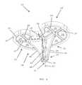
- a bicondylartibial tray component 10may include a tray portion 12 and a post portion 14 .
- the tray portion 12may include a superior side 16 , an inferior side 18 , and a peripheral wall 20 extending between the superior side 16 and the inferior side 18 .
- the superior side 16may be referred to as a joint-facing side since it faces toward the knee joint when the tibial tray component 10 is operatively mounted to a prepared proximal tibia.
- the superior side 16may include an articular surface for articulation with a natural or artificial distal femoral condyle or condyles. However, in the example shown, the superior side 16 is adapted for engagement with an articular insert component (not shown) and thus lacks an articular surface.
- the superior side 16includes a locking feature 22 and a superior surface 24 .
- the locking feature in this exampleincludes a posterior portion, seen in FIG. 1 , and/or an anterior portion, seen in FIG. 3 .
- the superior surface 24may be complementary to a corresponding inferior surface of an articular insert component. In this example, the superior surface 24 may be planar, concave, or convex.
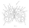
- the inferior side 18may be referred to as a bone-facing side since it faces toward the tibia when the tibial tray component 10 is operatively mounted to a prepared proximal tibia.
- the inferior side 18may include adaptations, features, and/or coatings to enhance short-term and/or long-term fixation directly to bone, or indirectly through a medium such as bone cement.
- the inferior side 18may include one or more ribs 26 and an inferior surface 28 .
- the ribs 26may be located anywhere on the inferior side 18 of the tibial tray portion 12 .
- the ribs 26may be located in areas that experience the highest service stresses and/or service forces during at least a portion of a gait cycle (a single gait cycle begins with ground contact by a selected foot, and ends with the next ground contact by the selected foot). These areas may, for example, extend across the tibial tray portion 12 generally from anterior to posterior, coinciding with the direction of knee flexion and extension motion. These areas may also include an arcuate quality coinciding with the direction of relative axial rotation of the tibia relative to the femur.
- Forces and/or stresses in the tibial tray component 10may be due to loading by a natural or artificial distal femoral condyle or condyles, and may be transferred directly due to direct articulation, or indirectly through an intermediate articular insert component. It will be appreciated that the force and/or stress distribution in any given tibial tray component 10 will depend upon many factors, such as the nominal or basic design of the implant component(s), their tolerances and materials, and the geometry, fit, and compliance of surrounding bony structures.
- an anterior-posterior rib 26 ′extends across each condyle of the tibial tray portion 12 .
- a central anterior-posterior rib 25extends across the tibial tray portion 12 and intersects the post portion 14 .
- Oblique ribs 27extend postero-laterally from the post portion 14 .
- a peripheral rib 29extends around the tibial tray portion 12 , congruent with the peripheral wall 20 .
- the ribsmay extend medio-laterally, oblique antero-laterally, radially, or annularly.
- the ribs 26may be angled, bent, curved, wavy, or otherwise depart from straight.
- the inferior surface 28may extend across the inferior side except where the ribs 26 are located. The inferior surface 28 may therefore appear to be segmental, discontinuous, or interrupted; however, the various portions of the inferior surface 28 may form a congruent continuous planar, convex, or concave surface.
- the interior corners formed between the ribs 26 and the inferior surface 28may be radiused or filleted to reduce stress concentrations; exterior corners may also be radiused or otherwise blunted.
- the peripheral wall 20may mimic, duplicate, or approximate a natural profile of a proximal tibia from a superior view. While the peripheral wall 20 is shown extending intact around the perimeter of the tibial tray portion 12 , one or more interruptions, apertures, passageways, protrusions, or other discontinuities may be present. As one example, the peripheral wall 20 may include an indentation for registration with a corresponding surgical instrument.
- the post portion 14extends from the inferior side 18 .
- a proximal portion 30 of the post portion 14couples or mounts to the inferior side 18 .
- the proximal portion 30 of the post portion 14may be located so as to intersect one or more ribs 26 .
- the proximal portion 30intersects the central anterior-posterior rib 25 and the oblique ribs 27 , as shown in FIG. 5 .
- a platform 34may be included at the intersection of the proximal portion 30 and the ribs 26 .
- a distal portion 32 of the post portion 14may terminate at a free end located a distance from the tibial tray portion 12 .
- the post portion 14may include one or more fins 36 which may project radially from a longitudinal axis 15 of the post portion 14 .
- the fin 36limits rotation of the tibial tray component 10 about the axis 15 when the tibial tray component 10 is operatively mounted to a prepared proximal tibia.
- the fin 36also adds structural support to the tibial tray component, particularly in the juncture between the inferior side 18 and the post portion 14 .
- each fin from the post portionmay be the same as, or different from, other fins around the post portion.
- the thickness of each finmay be the same as, or different from, other fins around the post portion.
- the length of each finmay be the same as, or different from, other fins around the post portion.
- the height and thickness of a finmay be constant or variable over the length of that fin.
- the anterior fin 36may project anteriorly from the post portion 14 , and may project in line with the central anterior-posterior rib 25 .
- the anterior fin 36may extend along the full length of the post portion 14 as shown in the illustrated example, or just a portion of the length.
- the anterior fin 36may extend along only the proximal 30 portion of the post portion 14 .
- the anterior fin 36may include a chamfer 44 or taper which reduces the height of the anterior fin 36 as the anterior fin progresses from proximal to distal along the post portion 14 .
- the chamfer 44extends along a portion of the fin 36 .
- the chamfer 44may extend the full length of the fin 36 in other examples.
- a straight chamferis shown, but convex or concave chamfers are contemplated.
- the chamfered fin 36occupies less volume than would a non-chamfered or straight full-height fin.
- the chamfer designreduces volume in the distal portion 32 of the post portion 14 , which is the leading end of the post portion 14 during insertion of the post portion into a prepared proximal tibia. Therefore, less bone removal is required where the tibia naturally tapers to the diaphysis.
- the right fin 38may project obliquely postero-laterally from the post portion 14 , and may project in line with the oblique ribs 27 .
- the right fin 38may extend along the full length of the post portion 14 as shown in the illustrated example, or just a portion of the length.
- the right fin 38may extend along only the proximal 30 portion of the post portion 14 .
- the right fin 38may include a chamfer 46 or taper which reduces the height of the right fin 38 as the right fin progresses from proximal to distal along the post portion 14 .
- the chamfer 46extends along a portion of the fin 38 .
- the chamfer 46may extend the full length of the fin 38 in other examples.
- a concave chamferis shown, but convex or straight chamfers are contemplated.
- the chamfered fin 38occupies less volume than would a non-chamfered or straight full-height fin.
- the chamfer designreduces volume in the distal portion 32 of the post portion 14 , which is the leading end of the post portion 14 during insertion of the post portion into a prepared proximal tibia. Therefore, less bone removal is required where the tibia naturally tapers to the diaphysis.
- the left fin 40may be a mirror image of the right fin 38 .
- the posterior fin 42may project posteriorly from the post portion 14 , and may project in line with the central anterior-posterior rib 25 .
- the posterior fin 42may extend along the full length of the post portion 14 as shown in the illustrated example, or just a portion of the length.
- the posterior fin 42may extend along only the proximal 30 portion of the post portion 14 .
- the posterior fin 42may include a chamfer 48 or taper which reduces the height of the posterior fin 42 as the posterior fin progresses from proximal to distal along the post portion 14 .
- the chamfer 48extends along a portion of the fin 42 .
- the chamfer 48may extend the full length of the fin 42 in other examples.
- a straight chamferis shown, but convex or concave chamfers are contemplated.
- the chamfered fin 42occupies less volume than would a non-chamfered or straight full-height fin.
- the chamfer designreduces volume in the distal portion 32 of the post portion 14 , which is the leading end of the post portion 14 during insertion of the post portion into a prepared proximal tibia. Therefore, less bone removal is required where the tibia naturally tapers to the diaphysis.
- a cut block assembly 50includes a cut block 52 and at least one pin 54 .
- the cut block assembly 50may be used during a total knee arthroplasty procedure to guide saw cuts to the distal femur.
- the cut block 52may include a superior side 56 , an inferior side 58 , and at least one lateral side 60 .
- the illustrated exampleincludes six lateral sides 60 , 62 , 64 , 66 , 68 , 70 .
- Lateral side 62may be referred to as a chamfer, as it forms oblique angles with adjacent lateral sides 60 and 64 .
- lateral side 70may be referred to as a chamfer, as it forms oblique angles with adjacent lateral sides 60 and 68 .
- the cut block 52may also include one or more slots 72 .
- the illustrated exampleincludes six slots 72 , 74 , 76 , 78 , 80 , 82 .
- Slot 74may intersect slot 72 to form a passageway through the cut block 52 between the superior side 56 and the inferior side 58 .
- Slot 76may intersect slot 78 .
- the cut block 52may also include one or more apertures 84 .
- the illustrated exampleincludes eight apertures 84 , 86 , 88 , 90 , 92 , 94 , 100 , 102 .
- Apertures 84 and 86intersect aperture 88 and extend no farther.
- apertures 92 and 94intersect aperture 90 and extend no farther.
- the cut block 52may also include one or more alcoves 96 .
- the illustrated exampleincludes two alcoves 96 , 98 .
- Alcove 96intersects aperture 88 and extends no farther.
- Alcove 98intersects aperture 90 and extends no farther.
- a proximal portion 104 of the pin 54may couple or mount to the cut block 52 , such as by integral formation, press fit, threads, latching, spring detents, magnetic detents, or the like.
- a distal portion 106 of the pin 54may extend away from the cut block 52 , and may terminate in a free-end.
- the proximal portion 104 of the pin 54may include an anti-rotation portion 108 with a square or rectangular cross section, as may be appreciated in FIGS. 7 and 9 .
- the portion 108may alternatively have a triangular or hexagonal shape, or another shape that resists rotation.
- the distal portion 106 of the pin 54may include a tapered portion 110 , as may be appreciated in FIGS.
- the tapered portionis conical, although pyramidal tapered portions are contemplated.
- the tapered portion 110may extend along a portion of the length of the pin 54 , or may extend along the entire length of the pin.
- the example shownincludes a second pin 112 , which may be identical to pin 54 .
- the cut block assembly 50may be used early in the preparation of a distal femur.
- two holesmay be drilled into the distal femur, one in the distal aspect of each condyle.
- a drill guide or jigmay be used to align, orient, and position the holes relative to anatomical landmarks on the femur and/or to each other.
- the free ends of the pins 54 , 112may be inserted into the holes, and the pins advanced until the superior side 56 contacts the distal aspect of the femur. As the pins 54 , 112 advance within the holes, the fit of the pins becomes tighter and tighter along the tapered portion 110 .
- the corners of the squareshave an interference fit with the holes.
- the cornersmay gradually cut into the bone or force the bone out of the way.
- the square pegs in the round holes, with an interference fit,provides secure fixation of the cut block assembly 50 in the host bone.
- the cut block assembly 50may thus be described as a four in one cut block assembly 150 .
- the four in one designationrefers to the slots 72 , 74 , 76 , 78 , 80 , 82 which may guide a cutting tool, such as a saw blade, to make anterior, posterior, and two chamfer cuts in the distal femur with one cut block, without repositioning the cut block.
- another cut block assembly 150includes a cut block 152 and at least one pin 154 .
- the cut block assembly 150may be used during a total knee arthroplasty procedure to guide saw cuts to the distal femur.
- the cut block 152may include a superior side 156 , an inferior side 158 , and at least one lateral side 160 .
- the illustrated exampleincludes six lateral sides 160 , 162 , 164 , 166 , 168 , 170 .
- Lateral side 162may be referred to as a chamfer, as it forms oblique angles with adjacent lateral sides 160 and 164 .
- lateral side 170may be referred to as a chamfer, as it forms oblique angles with adjacent lateral sides 160 and 168 .
- the cut block 152may also include one or more slots 172 .
- the illustrated exampleincludes six slots 172 , 174 , 176 , 178 , 180 , 182 .
- Slot 174may intersect slot 172 to form a passageway through the cut block 152 between the superior side 156 and the inferior side 158 .
- Slot 176may intersect slot 178 .
- the cut block 152may also include one or more apertures 184 .
- the illustrated exampleincludes eight apertures 184 , 186 , 188 , 190 , 192 , 194 , 200 , 202 .
- Apertures 184 and 186intersect aperture 188 and extend no farther.
- apertures 192 and 194intersect aperture 190 and extend no farther.
- the cut block 152may also include one or more alcoves 196 .
- the illustrated exampleincludes two alcoves 196 , 198 .
- Alcove 196intersects aperture 188 and extends no farther.
- Alcove 198intersects aperture 190 and extends no farther.
- the cut block 152may include at least one pin mounting location, such as hole 214 that receives at least a portion of the pin 154 .
- the hole(s)may include internal threads or other connection features or retention means for coupling to the pin 154 .
- the hole(s)may alternatively be made with a clearance fit, line to line fit, or interference fit with the pin 154 . Any hole may receive any pin.
- Other mounting locationsmay include internal or external features.
- the cut block 152may include indicia, markings, or labels to indicate the use of the holes 214 , 216 , 218 , 220 .
- the cut block 152includes markings “POS” adjacent to holes 214 , 216 , indicating that these holes are located for use with posterior referencing, as discussed below.
- the cut block 152includes markings “ANT” adjacent to holes 218 , 220 , indicating that these holes are located for use with anterior referencing. Holes 218 , 220 are also closer together than holes 214 , 216 to reduce the likelihood that a user will erroneously use the “ANT” holes 218 , 220 in the cut block 152 with posterior referencing, or vice versa.
- a proximal portion 204 of the pin 154may couple to the cut block 152 , such as by integral formation, press fit, threads, latching, spring detents, magnetic detents, or the like.
- a distal portion 206 of the pin 154may extend away from the cut block 152 , and may terminate in a free end.
- the proximal portion 204 of the pin 154may include an anti-rotation portion 208 with a square or rectangular cross section, as may be appreciated in FIG. 15 .
- the portion 208may alternatively have a triangular or hexagonal shape, or another shape that resists rotation.
- the distal portion 206 of the pin 154may include a tapered portion 210 , as may be appreciated in FIG.
- the tapered portionis conical, although pyramidal tapered portions are contemplated.
- the tapered portion 210may extend along a portion of the length of the pin 154 , or may extend along the entire length of the pin.
- the example shownincludes a second pin 212 , which may be identical to pin 154 .
- Pins 54 , 154 , 112 , 212may all be identical and interchangeable between cut blocks 52 , 152 .
- the cut block assembly 150may be used early in the preparation of a distal femur.
- two holesmay be drilled into the distal femur, one in the distal aspect of each condyle.
- a drill guide or jigmay be used to align, orient, and position the holes relative to anatomical landmarks on the femur and/or to each other.
- the location of the holesmay be determined based on referencing the anterior portion or the posterior portion of the distal femur.
- the pins 152 , 212may be secured in holes 218 , 220 , which are labeled “ANT” ( FIG. 15 ).
- the pins 152 , 212may be secured in holes 214 , 216 , which are labeled “POS” ( FIG. 15 ).
- the free ends of the pins 154 , 212may be inserted into the holes, and the pins advanced until the superior side 156 contacts the distal aspect of the femur.
- the fit of the pinsbecomes tighter and tighter along the tapered portion 210 .
- the corners of the squareshave an interference fit with the holes. The corners may gradually cut into the bone or force the bone out of the way.
- the square pegs in the round holes, with an interference fitprovides secure fixation of the cut block assembly 150 in the host bone.
- the cut block assembly 150may thus be described as a two position four in one cut block assembly 150 .
- the two position designationrefers to the “ANT” and “POS” positions for the pins.
- the four in one designationrefers to the slots 172 , 174 , 176 , 178 , 180 , 182 which may guide a cutting tool, such as a saw blade, to make anterior, posterior, and two chamfer cuts in the distal femur with one cut block, without repositioning the cut block.
- the components disclosed hereinmay be fabricated from metals, alloys, polymers, plastics, ceramics, glasses, composite materials, or combinations thereof, including but not limited to: PEEK, titanium, titanium alloys, commercially pure titanium grade 2, ASTM F67, Nitinol, cobalt chrome, stainless steel, ultra high molecular weight polyethylene (UHMWPE), biocompatible materials, and biodegradable materials, among others. Different materials may be used for different parts. Different materials may be used within a single part. Any component disclosed herein may be colored, coded or otherwise marked to make it easier for a user to identify the type and size of the component, the setting, the function(s) of the component, and the like.
- Coupledis defined as connected, although not necessarily directly, and not necessarily mechanically.
- a step of a method or an element of a devicethat “comprises,” “has,” “includes” or “contains” one or more features, possesses those one or more features, but is not limited to possessing only those one or more features.
- a device or structure that is configured in a certain wayis configured in at least that way, but may also be configured in ways that are not listed.
Landscapes
- Health & Medical Sciences (AREA)
- Life Sciences & Earth Sciences (AREA)
- Orthopedic Medicine & Surgery (AREA)
- Surgery (AREA)
- Biomedical Technology (AREA)
- Veterinary Medicine (AREA)
- Oral & Maxillofacial Surgery (AREA)
- Public Health (AREA)
- General Health & Medical Sciences (AREA)
- Engineering & Computer Science (AREA)
- Animal Behavior & Ethology (AREA)
- Heart & Thoracic Surgery (AREA)
- Physical Education & Sports Medicine (AREA)
- Transplantation (AREA)
- Medical Informatics (AREA)
- Molecular Biology (AREA)
- Dentistry (AREA)
- Nuclear Medicine, Radiotherapy & Molecular Imaging (AREA)
- Cardiology (AREA)
- Vascular Medicine (AREA)
- Prostheses (AREA)
Abstract
Description
Claims (12)
Priority Applications (1)
| Application Number | Priority Date | Filing Date | Title |
|---|---|---|---|
| US14/665,511US9820858B2 (en) | 2015-03-23 | 2015-03-23 | Knee implants and instruments |
Applications Claiming Priority (1)
| Application Number | Priority Date | Filing Date | Title |
|---|---|---|---|
| US14/665,511US9820858B2 (en) | 2015-03-23 | 2015-03-23 | Knee implants and instruments |
Publications (2)
| Publication Number | Publication Date |
|---|---|
| US20160278929A1 US20160278929A1 (en) | 2016-09-29 |
| US9820858B2true US9820858B2 (en) | 2017-11-21 |
Family
ID=56973874
Family Applications (1)
| Application Number | Title | Priority Date | Filing Date |
|---|---|---|---|
| US14/665,511Expired - Fee RelatedUS9820858B2 (en) | 2015-03-23 | 2015-03-23 | Knee implants and instruments |
Country Status (1)
| Country | Link |
|---|---|
| US (1) | US9820858B2 (en) |
Cited By (11)
| Publication number | Priority date | Publication date | Assignee | Title |
|---|---|---|---|---|
| US10925537B2 (en) | 2016-03-23 | 2021-02-23 | Canary Medical Inc. | Implantable reporting processor for an alert implant |
| US11071456B2 (en)* | 2014-09-17 | 2021-07-27 | Canary Medical Inc. | Devices, systems and methods for using and monitoring medical devices |
| US11191479B2 (en) | 2016-03-23 | 2021-12-07 | Canary Medical Inc. | Implantable reporting processor for an alert implant |
| US11730603B2 (en) | 2020-09-03 | 2023-08-22 | Globus Medical, Inc. | Systems and methods for knee arthroplasty |
| US11844697B2 (en) | 2020-09-03 | 2023-12-19 | Globus Medical, Inc. | Systems and methods for knee arthroplasty |
| US11998349B2 (en) | 2013-03-15 | 2024-06-04 | Canary Medical Inc. | Devices, systems and methods for monitoring hip replacements |
| US12097044B2 (en) | 2013-06-23 | 2024-09-24 | Canary Medical Inc. | Devices, systems and methods for monitoring knee replacements |
| US12142376B2 (en) | 2019-06-06 | 2024-11-12 | Canary Medical Inc. | Intelligent joint prosthesis |
| US12138181B2 (en) | 2019-06-06 | 2024-11-12 | Canary Medical Inc. | Intelligent joint prosthesis |
| EP4494609A1 (en)* | 2023-07-17 | 2025-01-22 | Aesculap AG | Orthopaedic knee joint prosthesis |
| US12440153B2 (en) | 2021-12-06 | 2025-10-14 | Canary Medical Inc. | Implantable reporting processor for an alert implant |
Families Citing this family (9)
| Publication number | Priority date | Publication date | Assignee | Title |
|---|---|---|---|---|
| AU201711075S (en)* | 2017-02-22 | 2017-03-06 | Orthopaedic surgery cutting block guide | |
| US10905436B2 (en) | 2017-03-02 | 2021-02-02 | Optimotion Implants, Llc | Knee arthroplasty systems and methods |
| US12083027B2 (en) | 2017-03-02 | 2024-09-10 | Optimotion Implants LLC | Universal femoral trial system and methods |
| US11406502B2 (en) | 2017-03-02 | 2022-08-09 | Optimotion Implants LLC | Orthopedic implants and methods |
| US10307260B2 (en)* | 2017-05-09 | 2019-06-04 | Depuy Ireland Unlimited Company | Tibial tray with fixation features |
| EP4268772A3 (en)* | 2017-10-26 | 2023-12-13 | Smith & Nephew, Inc. | Orthopedic implants |
| CA3209018A1 (en)* | 2022-08-22 | 2024-02-22 | Zimmer, Inc. | Tibial prosthesis with distal features for cemented fixation |
| USD1076093S1 (en) | 2023-01-25 | 2025-05-20 | Healthium Medtech Limited | Tibial button |
| EP4473945A1 (en)* | 2023-06-09 | 2024-12-11 | CeramTec GmbH | Tibial tray with a tibial tray shaft structure and an artificial knee joint |
Citations (54)
| Publication number | Priority date | Publication date | Assignee | Title |
|---|---|---|---|---|
| US5129909A (en)* | 1991-03-13 | 1992-07-14 | Sutherland Charles J | Apparatus and method for making precise bone cuts in total knee replacement |
| US5364401A (en)* | 1992-10-08 | 1994-11-15 | Wright Medical Technology, Inc. | External alignment system for preparing a femur for an implant |
| US5702461A (en)* | 1994-10-27 | 1997-12-30 | Biomedical Engineering Trust I | Prosthesis fixturing device |
| US5709689A (en)* | 1995-09-25 | 1998-01-20 | Wright Medical Technology, Inc. | Distal femur multiple resection guide |
| US5716361A (en)* | 1995-11-02 | 1998-02-10 | Masini; Michael A. | Bone cutting guides for use in the implantation of prosthetic joint components |
| US5824103A (en)* | 1997-05-12 | 1998-10-20 | Howmedica Inc. | Tibial prosthesis |
| US5911723A (en)* | 1996-05-28 | 1999-06-15 | Howmedice International Inc. | Surgical apparatus |
| US6258095B1 (en)* | 1998-03-28 | 2001-07-10 | Stryker Technologies Corporation | Methods and tools for femoral intermedullary revision surgery |
| US6355045B1 (en)* | 2000-12-28 | 2002-03-12 | Depuy Orthopaedics, Inc. | Method and apparatus for surgically preparing a tibia for implantation of a prosthetic implant component which has an offset stem |
| US20050075640A1 (en)* | 2003-10-03 | 2005-04-07 | Howmedica Osteonics Corp. | Punch apparatus and method for surgery |
| US20050209605A1 (en)* | 2002-12-20 | 2005-09-22 | Grimm James E | Navigated orthopaedic guide and method |
| US20060157543A1 (en)* | 2004-11-10 | 2006-07-20 | Stanley Abkowitz | Fine grain titanium-alloy article and articles with clad porous titanium surfaces |
| US20060184176A1 (en)* | 2005-02-17 | 2006-08-17 | Zimmer Technology, Inc. | Tibial trialing assembly and method of trialing a tibial implant |
| US7104997B2 (en)* | 2003-06-19 | 2006-09-12 | Lionberger Jr David R | Cutting guide apparatus and surgical method for use in knee arthroplasty |
| US20060241634A1 (en)* | 2005-02-21 | 2006-10-26 | Wright Medical Technology, Inc. | Instruments for minimally invasive surgery total knee arthroplasty |
| US20060265079A1 (en)* | 2005-05-19 | 2006-11-23 | Howmedica Osteonics Corp. | Modular keel tibial component |
| US20070010890A1 (en)* | 2005-07-08 | 2007-01-11 | Howmedica Osteonics Corp. | Modular tibial baseplate |
| US20070055268A1 (en)* | 2005-08-17 | 2007-03-08 | Aesculap Ag & Co. Kg | Cutting blocks for a surgical procedure and methods for using cutting blocks |
| US20070118138A1 (en)* | 2005-10-26 | 2007-05-24 | Jai-Gon Seo | Alignment and connection device of femur cutter and tibia cutter and method of knee arthroplasty using the same |
| US20070173946A1 (en)* | 2000-01-14 | 2007-07-26 | Bonutti Peter M | Inlaid articular implant |
| US20070203582A1 (en)* | 2006-02-28 | 2007-08-30 | Howmedica Osteonics Corp. | Modular tibial implant |
| US20070233140A1 (en)* | 2006-02-27 | 2007-10-04 | Biomet Manufacturing Corp. | Femoral adjustment device and associated method |
| US20070226986A1 (en)* | 2006-02-15 | 2007-10-04 | Ilwhan Park | Arthroplasty devices and related methods |
| US20070233137A1 (en)* | 2006-02-15 | 2007-10-04 | Jai-Gon Seo | Tibia cutter |
| US20070255412A1 (en)* | 2006-04-18 | 2007-11-01 | Binyamin Hajaj | Prosthetic device |
| US20070282451A1 (en)* | 2006-05-31 | 2007-12-06 | Biomet Manufacturing Corp. | Prosthesis and implementation system |
| US20070288030A1 (en)* | 2006-06-09 | 2007-12-13 | Biomet Manufacturing Corp. | Patient Specific Knee Alignment Guide And Associated Method |
| US20080015602A1 (en)* | 2006-06-22 | 2008-01-17 | Howmedica Osteonics Corp. | Cutting block for bone resection |
| US20080183177A1 (en)* | 2005-06-09 | 2008-07-31 | Biomet Manufacturing Corp. | Instrumentation And Method For Implanting A Curved Stem Tibial Tray |
| US20090084491A1 (en)* | 2007-09-25 | 2009-04-02 | Biomet Manufacturing Corp. | Cementless Tibial Tray |
| US20090125114A1 (en)* | 2007-10-10 | 2009-05-14 | Biomet Manufacturing Corp. | Knee joint prosthesis system and method for implantation |
| US20090265011A1 (en)* | 2008-04-17 | 2009-10-22 | Mandell Steven L | Femoral component of an artificial knee joint |
| US20100298947A1 (en)* | 2009-04-22 | 2010-11-25 | Unger Anthony S | Precision Total Knee Arthroplasty |
| US20110082559A1 (en)* | 2009-10-06 | 2011-04-07 | Wright Medical Technology, Inc. | Tibial implant base |
| US20110190898A1 (en)* | 2010-01-29 | 2011-08-04 | Lenz Nathaniel M | Cruciate-retaining knee prosthesis |
| USD651316S1 (en)* | 2010-06-04 | 2011-12-27 | Zimmer, Inc. | Femoral cut guide |
| US20120245589A1 (en)* | 2009-11-02 | 2012-09-27 | Synvasive Technology, Inc. | Bone positioning device and method |
| US8323288B2 (en)* | 2007-09-30 | 2012-12-04 | Depuy Products, Inc. | Customized patient-specific bone cutting blocks |
| US20130006377A1 (en)* | 2011-06-30 | 2013-01-03 | Waite Ii David W | Surgical instruments for use in surgically preparing a tibia for implantation of a prosthetic component |
| US20130006376A1 (en)* | 2011-06-30 | 2013-01-03 | Wogoman Thomas E | Method of using a trialing system for a knee prosthesis |
| US20130218284A1 (en)* | 2012-02-16 | 2013-08-22 | Mobius Medical LLC | Tibial baseplate assembly for knee joint prosthesis |
| US20130296865A1 (en)* | 2012-05-04 | 2013-11-07 | Luke J. Aram | Customized patient-specific orthopaedic pin guides |
| USD694884S1 (en)* | 2012-02-06 | 2013-12-03 | Zimmer, Inc. | Cut guide |
| US20130325014A1 (en)* | 2012-05-30 | 2013-12-05 | Benjamin J. Sordelet | Method of surgically preparing a patient's femur |
| US20140277539A1 (en)* | 2013-03-14 | 2014-09-18 | Michael A. Cook | Orthopaedic tibial prosthesis having tibial augments |
| US20140277541A1 (en)* | 2013-03-15 | 2014-09-18 | Joseph G. Wyss | Surgical instrument and method of same |
| US20140343558A1 (en)* | 2011-11-21 | 2014-11-20 | Smith & Nephew, Inc. | Methods of Designing Molds for Machining Cost Reduction |
| US20140364857A1 (en)* | 2012-02-07 | 2014-12-11 | Conformis, Inc. | Joint Arthroplasty Devices, Systems, and Methods |
| US20150025645A1 (en)* | 2012-02-17 | 2015-01-22 | Corentec Co., Ltd. | Artificial knee joint |
| US8986390B2 (en)* | 2011-06-30 | 2015-03-24 | Depuy (Ireland) | Method of trialing a knee prosthesis |
| US20150190236A1 (en)* | 2014-01-07 | 2015-07-09 | Derek James Wallace McMinn | Knee prosthesis |
| US20150202048A1 (en)* | 2012-08-24 | 2015-07-23 | Anatomic | Prosthetic tibial base and prosthetic tibial insert intended to be immobilized on such a prosthetic tibial base |
| US20150238316A1 (en)* | 2014-02-27 | 2015-08-27 | United Orthopedic Corp. | Stack-up assembly for tibial insert trial |
| US20150313727A1 (en)* | 2014-04-30 | 2015-11-05 | II David W. Waite | Tibial trial system for a knee prosthesis |
- 2015
- 2015-03-23USUS14/665,511patent/US9820858B2/ennot_activeExpired - Fee Related
Patent Citations (56)
| Publication number | Priority date | Publication date | Assignee | Title |
|---|---|---|---|---|
| US5129909A (en)* | 1991-03-13 | 1992-07-14 | Sutherland Charles J | Apparatus and method for making precise bone cuts in total knee replacement |
| US5364401A (en)* | 1992-10-08 | 1994-11-15 | Wright Medical Technology, Inc. | External alignment system for preparing a femur for an implant |
| US5702461A (en)* | 1994-10-27 | 1997-12-30 | Biomedical Engineering Trust I | Prosthesis fixturing device |
| US5709689A (en)* | 1995-09-25 | 1998-01-20 | Wright Medical Technology, Inc. | Distal femur multiple resection guide |
| US5716361A (en)* | 1995-11-02 | 1998-02-10 | Masini; Michael A. | Bone cutting guides for use in the implantation of prosthetic joint components |
| US5911723A (en)* | 1996-05-28 | 1999-06-15 | Howmedice International Inc. | Surgical apparatus |
| US5824103A (en)* | 1997-05-12 | 1998-10-20 | Howmedica Inc. | Tibial prosthesis |
| US6258095B1 (en)* | 1998-03-28 | 2001-07-10 | Stryker Technologies Corporation | Methods and tools for femoral intermedullary revision surgery |
| US20070173946A1 (en)* | 2000-01-14 | 2007-07-26 | Bonutti Peter M | Inlaid articular implant |
| US6355045B1 (en)* | 2000-12-28 | 2002-03-12 | Depuy Orthopaedics, Inc. | Method and apparatus for surgically preparing a tibia for implantation of a prosthetic implant component which has an offset stem |
| US20050209605A1 (en)* | 2002-12-20 | 2005-09-22 | Grimm James E | Navigated orthopaedic guide and method |
| US7104997B2 (en)* | 2003-06-19 | 2006-09-12 | Lionberger Jr David R | Cutting guide apparatus and surgical method for use in knee arthroplasty |
| US20050075640A1 (en)* | 2003-10-03 | 2005-04-07 | Howmedica Osteonics Corp. | Punch apparatus and method for surgery |
| US20060157543A1 (en)* | 2004-11-10 | 2006-07-20 | Stanley Abkowitz | Fine grain titanium-alloy article and articles with clad porous titanium surfaces |
| US20060184176A1 (en)* | 2005-02-17 | 2006-08-17 | Zimmer Technology, Inc. | Tibial trialing assembly and method of trialing a tibial implant |
| US20060241634A1 (en)* | 2005-02-21 | 2006-10-26 | Wright Medical Technology, Inc. | Instruments for minimally invasive surgery total knee arthroplasty |
| US20060265079A1 (en)* | 2005-05-19 | 2006-11-23 | Howmedica Osteonics Corp. | Modular keel tibial component |
| US20080183177A1 (en)* | 2005-06-09 | 2008-07-31 | Biomet Manufacturing Corp. | Instrumentation And Method For Implanting A Curved Stem Tibial Tray |
| US20070010890A1 (en)* | 2005-07-08 | 2007-01-11 | Howmedica Osteonics Corp. | Modular tibial baseplate |
| US7695519B2 (en)* | 2005-07-08 | 2010-04-13 | Howmedica Osteonics Corp. | Modular tibial baseplate |
| US20070055268A1 (en)* | 2005-08-17 | 2007-03-08 | Aesculap Ag & Co. Kg | Cutting blocks for a surgical procedure and methods for using cutting blocks |
| US20070118138A1 (en)* | 2005-10-26 | 2007-05-24 | Jai-Gon Seo | Alignment and connection device of femur cutter and tibia cutter and method of knee arthroplasty using the same |
| US20070226986A1 (en)* | 2006-02-15 | 2007-10-04 | Ilwhan Park | Arthroplasty devices and related methods |
| US20070233137A1 (en)* | 2006-02-15 | 2007-10-04 | Jai-Gon Seo | Tibia cutter |
| US20070233140A1 (en)* | 2006-02-27 | 2007-10-04 | Biomet Manufacturing Corp. | Femoral adjustment device and associated method |
| US20070203582A1 (en)* | 2006-02-28 | 2007-08-30 | Howmedica Osteonics Corp. | Modular tibial implant |
| US20070255412A1 (en)* | 2006-04-18 | 2007-11-01 | Binyamin Hajaj | Prosthetic device |
| US20070282451A1 (en)* | 2006-05-31 | 2007-12-06 | Biomet Manufacturing Corp. | Prosthesis and implementation system |
| US20070288030A1 (en)* | 2006-06-09 | 2007-12-13 | Biomet Manufacturing Corp. | Patient Specific Knee Alignment Guide And Associated Method |
| US20080015602A1 (en)* | 2006-06-22 | 2008-01-17 | Howmedica Osteonics Corp. | Cutting block for bone resection |
| US20090084491A1 (en)* | 2007-09-25 | 2009-04-02 | Biomet Manufacturing Corp. | Cementless Tibial Tray |
| US8323288B2 (en)* | 2007-09-30 | 2012-12-04 | Depuy Products, Inc. | Customized patient-specific bone cutting blocks |
| US20090125114A1 (en)* | 2007-10-10 | 2009-05-14 | Biomet Manufacturing Corp. | Knee joint prosthesis system and method for implantation |
| US20090265011A1 (en)* | 2008-04-17 | 2009-10-22 | Mandell Steven L | Femoral component of an artificial knee joint |
| US20100298947A1 (en)* | 2009-04-22 | 2010-11-25 | Unger Anthony S | Precision Total Knee Arthroplasty |
| US20110082559A1 (en)* | 2009-10-06 | 2011-04-07 | Wright Medical Technology, Inc. | Tibial implant base |
| US20120245589A1 (en)* | 2009-11-02 | 2012-09-27 | Synvasive Technology, Inc. | Bone positioning device and method |
| US20110190898A1 (en)* | 2010-01-29 | 2011-08-04 | Lenz Nathaniel M | Cruciate-retaining knee prosthesis |
| USD651316S1 (en)* | 2010-06-04 | 2011-12-27 | Zimmer, Inc. | Femoral cut guide |
| US20130006377A1 (en)* | 2011-06-30 | 2013-01-03 | Waite Ii David W | Surgical instruments for use in surgically preparing a tibia for implantation of a prosthetic component |
| US20130006376A1 (en)* | 2011-06-30 | 2013-01-03 | Wogoman Thomas E | Method of using a trialing system for a knee prosthesis |
| US20150134070A1 (en)* | 2011-06-30 | 2015-05-14 | Depuy (Ireland) | Surgical instruments and method for use in surgically preparing a tibia for implantation of a prosthetic component |
| US8986390B2 (en)* | 2011-06-30 | 2015-03-24 | Depuy (Ireland) | Method of trialing a knee prosthesis |
| US20140343558A1 (en)* | 2011-11-21 | 2014-11-20 | Smith & Nephew, Inc. | Methods of Designing Molds for Machining Cost Reduction |
| USD694884S1 (en)* | 2012-02-06 | 2013-12-03 | Zimmer, Inc. | Cut guide |
| US20140364857A1 (en)* | 2012-02-07 | 2014-12-11 | Conformis, Inc. | Joint Arthroplasty Devices, Systems, and Methods |
| US20130218284A1 (en)* | 2012-02-16 | 2013-08-22 | Mobius Medical LLC | Tibial baseplate assembly for knee joint prosthesis |
| US20150025645A1 (en)* | 2012-02-17 | 2015-01-22 | Corentec Co., Ltd. | Artificial knee joint |
| US20130296865A1 (en)* | 2012-05-04 | 2013-11-07 | Luke J. Aram | Customized patient-specific orthopaedic pin guides |
| US20130325014A1 (en)* | 2012-05-30 | 2013-12-05 | Benjamin J. Sordelet | Method of surgically preparing a patient's femur |
| US20150202048A1 (en)* | 2012-08-24 | 2015-07-23 | Anatomic | Prosthetic tibial base and prosthetic tibial insert intended to be immobilized on such a prosthetic tibial base |
| US20140277539A1 (en)* | 2013-03-14 | 2014-09-18 | Michael A. Cook | Orthopaedic tibial prosthesis having tibial augments |
| US20140277541A1 (en)* | 2013-03-15 | 2014-09-18 | Joseph G. Wyss | Surgical instrument and method of same |
| US20150190236A1 (en)* | 2014-01-07 | 2015-07-09 | Derek James Wallace McMinn | Knee prosthesis |
| US20150238316A1 (en)* | 2014-02-27 | 2015-08-27 | United Orthopedic Corp. | Stack-up assembly for tibial insert trial |
| US20150313727A1 (en)* | 2014-04-30 | 2015-11-05 | II David W. Waite | Tibial trial system for a knee prosthesis |
Cited By (31)
| Publication number | Priority date | Publication date | Assignee | Title |
|---|---|---|---|---|
| US11998349B2 (en) | 2013-03-15 | 2024-06-04 | Canary Medical Inc. | Devices, systems and methods for monitoring hip replacements |
| US12097044B2 (en) | 2013-06-23 | 2024-09-24 | Canary Medical Inc. | Devices, systems and methods for monitoring knee replacements |
| US11786126B2 (en) | 2014-09-17 | 2023-10-17 | Canary Medical Inc. | Devices, systems and methods for using and monitoring medical devices |
| US12426784B2 (en) | 2014-09-17 | 2025-09-30 | Canary Medical Inc. | Devices, systems and methods for using and monitoring medical devices |
| US12285234B2 (en) | 2014-09-17 | 2025-04-29 | Canary Medical Inc. | Devices, systems and methods for using and monitoring medical devices |
| US11071456B2 (en)* | 2014-09-17 | 2021-07-27 | Canary Medical Inc. | Devices, systems and methods for using and monitoring medical devices |
| US11596308B2 (en) | 2014-09-17 | 2023-03-07 | Canary Medical Inc. | Devices, systems and methods for using and monitoring medical devices |
| US11638555B2 (en) | 2016-03-23 | 2023-05-02 | Canary Medical Inc. | Implantable reporting processor for an alert implant |
| US12226228B2 (en) | 2016-03-23 | 2025-02-18 | Canary Medical Inc. | Implantable reporting processor for an alert implant |
| US11779273B2 (en) | 2016-03-23 | 2023-10-10 | Canary Medical Inc. | Implantable reporting processor for an alert implant |
| US10925537B2 (en) | 2016-03-23 | 2021-02-23 | Canary Medical Inc. | Implantable reporting processor for an alert implant |
| US11020053B2 (en) | 2016-03-23 | 2021-06-01 | Canary Medical Inc. | Implantable reporting processor for an alert implant |
| US11896391B2 (en) | 2016-03-23 | 2024-02-13 | Canary Medical Inc. | Implantable reporting processor for an alert implant |
| US11540772B2 (en) | 2016-03-23 | 2023-01-03 | Canary Medical Inc. | Implantable reporting processor for an alert implant |
| US11191479B2 (en) | 2016-03-23 | 2021-12-07 | Canary Medical Inc. | Implantable reporting processor for an alert implant |
| US12419574B2 (en) | 2016-03-23 | 2025-09-23 | Canary Medical Inc. | Implantable reporting processor for an alert implant |
| US12285267B2 (en) | 2016-03-23 | 2025-04-29 | Canary Medical Inc. | Implantable reporting processor for an alert implant |
| US11045139B2 (en) | 2016-03-23 | 2021-06-29 | Canary Medical Inc. | Implantable reporting processor for an alert implant |
| US12159714B2 (en) | 2019-06-06 | 2024-12-03 | Canary Medical Inc. | Intelligent joint prosthesis |
| US12176104B2 (en) | 2019-06-06 | 2024-12-24 | Canary Medical Inc. | Intelligent joint prosthesis |
| US12232985B2 (en) | 2019-06-06 | 2025-02-25 | Canary Medical Inc. | Intelligent joint prosthesis |
| US12232984B2 (en) | 2019-06-06 | 2025-02-25 | Canary Medical Inc. | Intelligent joint prosthesis |
| US12239552B2 (en) | 2019-06-06 | 2025-03-04 | Canary Medical Inc. | Intelligent joint prosthesis |
| US12138181B2 (en) | 2019-06-06 | 2024-11-12 | Canary Medical Inc. | Intelligent joint prosthesis |
| US12142376B2 (en) | 2019-06-06 | 2024-11-12 | Canary Medical Inc. | Intelligent joint prosthesis |
| US12293828B2 (en) | 2019-06-06 | 2025-05-06 | Canary Medical Inc. | Intelligent joint prosthesis |
| US11730603B2 (en) | 2020-09-03 | 2023-08-22 | Globus Medical, Inc. | Systems and methods for knee arthroplasty |
| US12121449B2 (en) | 2020-09-03 | 2024-10-22 | Globus Medical, Inc. | Systems and methods for knee arthroplasty |
| US11844697B2 (en) | 2020-09-03 | 2023-12-19 | Globus Medical, Inc. | Systems and methods for knee arthroplasty |
| US12440153B2 (en) | 2021-12-06 | 2025-10-14 | Canary Medical Inc. | Implantable reporting processor for an alert implant |
| EP4494609A1 (en)* | 2023-07-17 | 2025-01-22 | Aesculap AG | Orthopaedic knee joint prosthesis |
Also Published As
| Publication number | Publication date |
|---|---|
| US20160278929A1 (en) | 2016-09-29 |
Similar Documents
| Publication | Publication Date | Title |
|---|---|---|
| US9820858B2 (en) | Knee implants and instruments | |
| JP7400045B2 (en) | System and method for preparing a patient's femur for orthopedic joint replacement procedures | |
| EP2313029B1 (en) | Sloped knee prosthesis system | |
| EP3082658B1 (en) | Low profile mobile/fixed prosthetic knee systems | |
| EP3275406B1 (en) | Total knee implant prosthesis assembly | |
| JP6965281B2 (en) | Orthopedic surgical instrument system for surgical preparation of a patient's femur | |
| CN110636818B (en) | Femoral prosthesis with size augmentation and size reduction capabilities | |
| US20140371866A1 (en) | Tibial implant devices, systems, and methods | |
| US20040143336A1 (en) | Two-piece modular patellar prosthetic system | |
| US20060241635A1 (en) | Prosthetic revision knee system | |
| JP2004202233A (en) | Artificial thighbone constituent equipped with modular sleeve | |
| EP2008621A1 (en) | Orthopaedic prosthesis | |
| EP3355834B1 (en) | Tibial prosthesis for tibia with varus resection | |
| EP3302370B1 (en) | Bearing trial system | |
| JP2022153485A (en) | Gap gage and unit capable of checking flexion gap prior to cutting of posterior femur | |
| US20170367833A1 (en) | Cruciate retaining knee implants and methods for implanting cruciate retaining knee implants | |
| CN114040733A (en) | Orthopedic implant system with bone-protecting features | |
| AU2004202933A1 (en) | Multi-piece modular patellar prosthetic system |
Legal Events
| Date | Code | Title | Description |
|---|---|---|---|
| AS | Assignment | Owner name:MODAL MANUFACTURING, LLC, FLORIDA Free format text:ASSIGNMENT OF ASSIGNORS INTEREST;ASSIGNORS:HARRIS, THOMAS BRADLEY;RYNEARSON, ANDREW MEREDITH;REEL/FRAME:035231/0354 Effective date:20150323 | |
| STCF | Information on status: patent grant | Free format text:PATENTED CASE | |
| AS | Assignment | Owner name:HARRIS, THOMAS BRADLEY, FLORIDA Free format text:ASSIGNMENT OF ASSIGNORS INTEREST;ASSIGNOR:MODAL MANUFACTURING, LLC;REEL/FRAME:046649/0668 Effective date:20180813 | |
| AS | Assignment | Owner name:MODAL MANUFACTURING, LLC, FLORIDA Free format text:ASSIGNMENT OF ASSIGNORS INTEREST;ASSIGNOR:HARRIS, THOMAS BRADLEY;REEL/FRAME:047940/0742 Effective date:20190108 | |
| FEPP | Fee payment procedure | Free format text:MAINTENANCE FEE REMINDER MAILED (ORIGINAL EVENT CODE: REM.); ENTITY STATUS OF PATENT OWNER: SMALL ENTITY | |
| LAPS | Lapse for failure to pay maintenance fees | Free format text:PATENT EXPIRED FOR FAILURE TO PAY MAINTENANCE FEES (ORIGINAL EVENT CODE: EXP.); ENTITY STATUS OF PATENT OWNER: SMALL ENTITY | |
| STCH | Information on status: patent discontinuation | Free format text:PATENT EXPIRED DUE TO NONPAYMENT OF MAINTENANCE FEES UNDER 37 CFR 1.362 | |
| FP | Lapsed due to failure to pay maintenance fee | Effective date:20211121 |