US9818053B2 - Identification of objects using frequency characteristics of RFID tags - Google Patents
Identification of objects using frequency characteristics of RFID tagsDownload PDFInfo
- Publication number
- US9818053B2 US9818053B2US12/747,548US74754808AUS9818053B2US 9818053 B2US9818053 B2US 9818053B2US 74754808 AUS74754808 AUS 74754808AUS 9818053 B2US9818053 B2US 9818053B2
- Authority
- US
- United States
- Prior art keywords
- frequency
- rfid tags
- information
- rfid
- detected
- Prior art date
- Legal status (The legal status is an assumption and is not a legal conclusion. Google has not performed a legal analysis and makes no representation as to the accuracy of the status listed.)
- Active, expires
Links
Images


Classifications
- G—PHYSICS
- G06—COMPUTING OR CALCULATING; COUNTING
- G06K—GRAPHICAL DATA READING; PRESENTATION OF DATA; RECORD CARRIERS; HANDLING RECORD CARRIERS
- G06K17/00—Methods or arrangements for effecting co-operative working between equipments covered by two or more of main groups G06K1/00 - G06K15/00, e.g. automatic card files incorporating conveying and reading operations
- G—PHYSICS
- G06—COMPUTING OR CALCULATING; COUNTING
- G06K—GRAPHICAL DATA READING; PRESENTATION OF DATA; RECORD CARRIERS; HANDLING RECORD CARRIERS
- G06K19/00—Record carriers for use with machines and with at least a part designed to carry digital markings
- G06K19/06—Record carriers for use with machines and with at least a part designed to carry digital markings characterised by the kind of the digital marking, e.g. shape, nature, code
- G06K19/067—Record carriers with conductive marks, printed circuits or semiconductor circuit elements, e.g. credit or identity cards also with resonating or responding marks without active components
- G06K19/0672—Record carriers with conductive marks, printed circuits or semiconductor circuit elements, e.g. credit or identity cards also with resonating or responding marks without active components with resonating marks
- G—PHYSICS
- G06—COMPUTING OR CALCULATING; COUNTING
- G06K—GRAPHICAL DATA READING; PRESENTATION OF DATA; RECORD CARRIERS; HANDLING RECORD CARRIERS
- G06K19/00—Record carriers for use with machines and with at least a part designed to carry digital markings
- G06K19/06—Record carriers for use with machines and with at least a part designed to carry digital markings characterised by the kind of the digital marking, e.g. shape, nature, code
- G06K19/067—Record carriers with conductive marks, printed circuits or semiconductor circuit elements, e.g. credit or identity cards also with resonating or responding marks without active components
- G06K19/07—Record carriers with conductive marks, printed circuits or semiconductor circuit elements, e.g. credit or identity cards also with resonating or responding marks without active components with integrated circuit chips
- G06K19/0723—Record carriers with conductive marks, printed circuits or semiconductor circuit elements, e.g. credit or identity cards also with resonating or responding marks without active components with integrated circuit chips the record carrier comprising an arrangement for non-contact communication, e.g. wireless communication circuits on transponder cards, non-contact smart cards or RFIDs
- G06K19/0724—Record carriers with conductive marks, printed circuits or semiconductor circuit elements, e.g. credit or identity cards also with resonating or responding marks without active components with integrated circuit chips the record carrier comprising an arrangement for non-contact communication, e.g. wireless communication circuits on transponder cards, non-contact smart cards or RFIDs the arrangement being a circuit for communicating at a plurality of frequencies, e.g. for managing time multiplexed communication over at least two antennas of different types
- G—PHYSICS
- G06—COMPUTING OR CALCULATING; COUNTING
- G06K—GRAPHICAL DATA READING; PRESENTATION OF DATA; RECORD CARRIERS; HANDLING RECORD CARRIERS
- G06K7/00—Methods or arrangements for sensing record carriers, e.g. for reading patterns
- G06K7/10—Methods or arrangements for sensing record carriers, e.g. for reading patterns by electromagnetic radiation, e.g. optical sensing; by corpuscular radiation
- G06K7/10009—Methods or arrangements for sensing record carriers, e.g. for reading patterns by electromagnetic radiation, e.g. optical sensing; by corpuscular radiation sensing by radiation using wavelengths larger than 0.1 mm, e.g. radio-waves or microwaves
- G06K7/10019—Methods or arrangements for sensing record carriers, e.g. for reading patterns by electromagnetic radiation, e.g. optical sensing; by corpuscular radiation sensing by radiation using wavelengths larger than 0.1 mm, e.g. radio-waves or microwaves resolving collision on the communication channels between simultaneously or concurrently interrogated record carriers.
- G06K7/10069—Methods or arrangements for sensing record carriers, e.g. for reading patterns by electromagnetic radiation, e.g. optical sensing; by corpuscular radiation sensing by radiation using wavelengths larger than 0.1 mm, e.g. radio-waves or microwaves resolving collision on the communication channels between simultaneously or concurrently interrogated record carriers. the collision being resolved in the frequency domain, e.g. by hopping from one frequency to the other
- G06K2017/0035—
Definitions
- the present applicationrelates to object identification by way of radio-frequency identification (RFID) tags.
- RFIDradio-frequency identification
- An RFID tagtypically includes two portions: 1) an integrated circuit for storing information, processing information, and modulating or demodulating a radio frequency (RF) signal (and possibly other specialized functions); and 2) an antenna for receiving and transmitting radio frequency signals.
- RFID tagscan include passive RFID tags, active RFID tags, and semi-active RFID tags.
- a passive RFID tagis powered by incoming radio frequency signals received from an RFID reader, and does not include an internal power source.
- an active RFID tagincludes an internal power source for powering an integrated circuit and transmitting a radio frequency signal to an RFID reader.
- a semi-active RFID taghas an internal power source to supply power to an integrated circuit but not to provide power for broadcasting a signal and vice versa.
- RFID tagsare designed to communicate over one of four predefined frequency ranges: low (approximately 125 KHz), high (approximately 13.56 MHz), ultra high frequency (UHF) (approximately 850 MHz to 900 MHz), or microwave (approximately 2.45 GHz).
- Lowapproximately 125 KHz
- highapproximately56 MHz
- ultra high frequencyUHF
- microwaveapproximately 2.45 GHz
- Non-similar frequencieshave different characteristics with respect to radio waves; accordingly, different frequencies are better suited for different applications with respect to RFID technologies.
- RFID tags that are designed to transmit at low frequenciesrequire less power when compared to RFID tags that are designed to transmit at ultra high frequencies (UHF).
- UHFultra high frequencies
- information transmitted at a low frequencyis better able to penetrate non-metallic substances when compared with information transmitted at UHF.
- informationmay be transmitted over greater distances using UHF.
- a palletmay include a thousand items and thus may include a thousand RFID tags. If the RFID tags are passive, each of the thousand RFID tags must be powered by radio waves transmitted by an RFID reader, each integrated circuit must be accessed, and information must be transmitted from each RFID tag. This would require a significant amount of time.
- a method for identifying an objectcomprises detecting a frequency over which an RFID tag communicates and identifying the object based at least in part upon the detected frequency.
- an apparatus that identifies an objectcomprises a frequency detector that detects a frequency over which an RFID tag communicates and an object identifier that identifies the object based at least in part upon the detected frequency.
- a computer-readable mediumcomprising instructions that, when executed by a processor, perform acts of performing a frequency scan for spectral agile radio RFID tags, preparing a list of detected RFID tags based at least in part upon frequencies detected during the frequency scan, constructing a list of potential objects based at least in part upon the detected frequencies, and constructing a list of identified objects based at least in part upon a context assigned to the spectral agile radio RFID tags.
- a data repositoryincludes frequency patterns that correspond to a plurality of objects, wherein an object is identified by comparing an observed frequency pattern with at least a subset of the frequency patterns in the data repository.
- FIG. 1depicts an apparatus that identifies an object.
- FIG. 2depicts an apparatus that identifies an object.
- FIG. 3depicts an apparatus that identifies an object.
- FIG. 4depicts an apparatus that identifies an object.
- FIG. 5depicts a method for identifying an object.
- FIG. 6depicts a method for identifying an object.
- FIG. 7depicts a method for identifying an object.
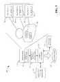
- the apparatus 100includes a plurality of RFID tags 102 , 104 , and 106 that correspond to the object 108 .
- the object 108is for instance a tangible object, such as a medical supply cart that includes a plurality of different types of medicines and/or medical equipment, or an intangible object, such as a treatment plan for a patient.
- the RFID tags 102 , 104 , and 106are embedded in the object 108 , attached to the object 108 , and/or embedded or attached to objects that collectively define an intangible object.
- the RFID tags 102 , 104 , and 106are passive RFID tags, active RFID tags, semi-active RFID tags, or a combination thereof. Moreover, the RFID tags are not confined to the four frequencies that are typically assigned to RFID tags, but instead are capable of communicating over various portions of the frequency spectrum. For instance, spectrum agile radio (SARA) technologies open spectrum use in space and time to allow devices to transmit over frequencies that have heretofore been restricted to certain types of communications. Accordingly, as alluded to above, the RFID tags 102 , 104 , and 106 are designed to communicate over a wide range of frequencies (e.g., in accordance with SARA protocols).
- SARAspectrum agile radio
- An RFID reader 110optionally includes a transmitter (not shown) that emits radio waves that provide power to RFID tags 102 , 104 , and 106 if they are passive RFID tags.
- the RFID reader 110also receives signals transmitted from the RFID tags 102 , 104 , and 106 , wherein the signals include information that identifies the RFID tags 102 , 104 , and 106 and/or other content stored in memory.
- the apparatus 100additionally includes a frequency detector 112 that detects a frequency used by the RFID tags 102 , 104 , and 106 to transmit information.
- the frequency detector 112is capable of performing a frequency sweep and detecting frequencies used by the RFID tags 102 , 104 , and 106 to transmit information, wherein a frequency sweep can monitor frequencies that are continuous over a range or monitoring discrete frequencies.
- the apparatus 100also optionally includes a location detector 114 that analyzes frequencies used by the RFID tags 102 , 104 , and 106 and detects locations of the RFID tags 102 , 104 , and 106 relative to the RFID reader 110 and relative to one another based upon the detected frequencies and strength of signals emitted by the RFID tags 102 , 104 , and 106 .
- a frequency pattern generator 116receives frequency information detected by the frequency detector 112 and creates a frequency pattern based upon the received information.
- Frequency patterns created by the frequency pattern generator 116have the general form of ⁇ Af1; Bf2; . . . . Xfn ⁇ , where A, B, and X are integers that indicate a number of RFID tags that transmit information over frequencies f, and n is a number of frequencies detected.
- a frequency patternincludes frequencies used by the RFID tags 102 , 104 , and 106 and a number of RFID tags that use each frequency.
- An example frequency patternis provided below for illustrative purposes.
- the apparatusalso optionally includes a context analyzer 118 that determines a context corresponding to the apparatus 100 .
- the determined contextindicates, for instance, that the object 108 is an object related to healthcare (e.g., a healthcare object), an object in an industrial setting (e.g., an industrial object), an object in a retail setting (e.g., a retail object), etc.
- An object identifier 120receives the frequency pattern created by the frequency pattern generator 116 and compares the frequency pattern to known frequency patterns in a frequency pattern repository 122 , which is a computer-readable medium.
- the object identifier 120also optionally uses contextual information provided by the context analyzer 118 when comparing the received frequency pattern with frequency patterns in the frequency pattern repository 122 .
- the object identifier 120Based upon the comparison of the received frequency pattern and the frequency patterns in the frequency pattern repository 122 , the object identifier 120 outputs an identification 124 that identifies the object 108 .
- the identification 124is output to a display screen or a printer, and/or stored in a computer-readable medium, or the like.
- the object 108is identified based primarily on frequencies used by the RFID tags 102 , 104 , and 106 and not based solely upon content of the RFID tags 102 , 104 , and 106 . Therefore, the object 108 may be identified in less time using less power when compared to conventional manners for identifying objects by way of RFID technologies, as unique identity and content need not be read from each RFID tag to identify an object.
- the RFID reader 110 , the frequency pattern generator 116 , the context analyzer 118 , the object identifier 120 , and the frequency pattern repository 122may be included in a single device, such as a handheld apparatus. In another example, at least some of the aforementioned modules and the frequency pattern repository 122 may be included in separate devices; for instance, the frequency pattern repository 122 may be located on a server that is accessible by way of the Internet or an intranet.
- the object to be identifiedis abstract—a treatment plan for a patient 202 , such as what medicine a patient requires, location (e.g., operating room, emergency room, . . . ) a patient should be directed to, and the like.
- a plurality of devicesare attached to the patient 202 or embedded in the patient 202 , and each of the devices has a corresponding RFID tag.
- a first RFID tag 204corresponds to a microphone
- a second RFID tag 206corresponds to an oxygen sensor
- a third RFID tag 208corresponds to a blood-pressure sensor
- a fourth RFID tag 210corresponds to an accelerometer
- a fifth RFID tag 212corresponds to a temperature sensor
- a sixth RFID tag 214corresponds to an electrocardiogram.
- a subset of the RFID tags 204 - 214are designed to transmit information at frequencies that are conventionally not used by RFID tags—accordingly, a frequency at which an RFID tag transmits information is indicative of an identity of the RFID tag and thus indicative of an entity that corresponds to the RFID tag.
- a subset of the RFID tagsmay be designed in accordance with SARA protocols.
- the RFID reader 110outputs radio waves that are used to power the RFID tags 204 - 214 if they are passive RFID tags.
- the RFID reader 110also optionally receives content of one or more of the RFID tags 204 - 214 .
- the frequency detector 112performs a frequency scan on the patient 202 and detects frequencies used by the RFID tags 204 - 214 .
- the frequency pattern generator 116generates a frequency pattern based upon the frequencies detected by the frequency detector 112 .
- the object identifier 120receives the frequency pattern determined by the frequency pattern generator 116 and also receives a current context (e.g., healthcare treatment plans) from the context analyzer 118 .
- a current contexte.g., healthcare treatment plans
- the object identifier 120accesses the frequency pattern repository 122 and compares frequency patterns therein that correspond to the determined context with the frequency pattern generated by the frequency pattern generator 116 .
- the object identifier 120identifies the object (e.g., the treatment plan for the patient 202 ) based upon the comparison and outputs the identification 124 .
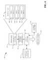
- FIG. 3an example apparatus 300 for identifying an object is illustrated.
- the objectis again intangible—the configuration of healthcare equipment with respect to a patient 302 .
- First and second pieces of equipment, 304 and 306monitor parameters of the patient 302 .
- the first piece of equipment 304is a processing device that processes the heart rate of the patient 302
- the second piece of equipment 306is a processing device that processes the blood pressure of the patient 302 .
- a third piece of equipment 308is a display monitor that displays processed information output by the first and second pieces of equipment 304 and 306 , respectively.
- First, second, and third RFID tags 310 , 312 , and 314correspond with the first, second, and third pieces of equipment 304 , 306 , and 308 , respectively.
- Fourth and fifth RFID tags 316 and 318correspond to sensors, coupled to the patient 302 , that are used to detect heart rate and blood pressure of the patient, and correspond to equipment 304 and 306 , respectively.
- frequencies used by the RFID tags 310 - 318are not confined to conventional frequencies of RFID tags, and thus a frequency is indicative of an identity of an object.
- the RFID reader 110outputs radio waves that are used to power the RFID tags 310 - 318 if they are passive RFID tags.
- the RFID reader 110also optionally receives content of one or more of the RFID tags 310 - 318 .
- the frequency detector 112performs a frequency sweep on the patient and detects frequencies used by the RFID tags 310 - 318 , and the frequency pattern generator 116 generates a frequency pattern based upon the frequencies detected by the frequency detector 112 .
- the object identifier 120receives the frequency pattern determined by the frequency pattern generator 116 and also receives a current context (e.g., healthcare configurations) from the context analyzer 118 .
- a current contexte.g., healthcare configurations
- the contextis either set by an operator of the apparatus 300 or automatically set based upon location of the apparatus 300 , time of day, day of week, or other suitable information.
- the object identifier 120accesses the frequency pattern repository 122 and compares frequency patterns therein that correspond to the determined context with the frequency pattern generated by the frequency pattern generator 116 .
- the object identifier 120identifies the object (e.g., the configuration of healthcare equipment with respect to the patient 202 ) based upon the comparison and outputs the identification 124 .
- the object to be identifiedis a composition of substances on a medical cart 402 .
- the medical cart 402may include several hundred medicine containers, and it may be desirable to quickly determine if the medical cart 402 includes any controlled substances.
- frequencies used by RFID tags on the medical cart 402can be determined and used to ascertain a composition of substances.
- the medical cart 402includes three different items 404 , 406 , and 408 .
- the items 404 - 408are containers that include medical substances.
- Each of the items 404 , 406 , and 408has a corresponding RFID tag 410 , 412 , and 414 , wherein the RFID tags 410 - 414 transmit at different frequencies (e.g., frequencies that are not conventionally used by RFID tags).
- the RFID reader 110outputs radio waves that are used to power the RFID tags 410 - 414 if they are passive RFID tags.
- the frequency detector 112performs a frequency scan on the medical cart 402 and detects frequencies used by the RFID tags 410 - 414 .
- the frequency pattern generator 116generates a frequency pattern based upon the frequencies detected by the frequency detector 112 .
- the object identifier 120receives the frequency pattern determined by the frequency pattern generator 116 and also receives a current context (e.g., medical cart compositions) from the context analyzer 118 .
- the object identifier 120accesses the frequency pattern repository 122 and compares frequency patterns therein that correspond to the determined context with the frequency pattern generated by the frequency pattern generator 116 .
- the object identifier 120identifies the object (e.g., the composition of the medical cart 402 ) based upon the comparison and outputs the identification 124 . Similar comparisons can be used to track inventory.
- RFID tagse.g., a frequency pattern
- location information determined by the location detector 114can be used together with the frequency information to identify an object (e.g., location of items with respect to one another may be indicative of object identity).
- identity of one or more RFID tags and/or content of one or more RFID tagsmay be used to identify an object.
- an RFID tagmay be represented as a tuple of ⁇ f, id, content>, where f is the frequency that the RFID tag uses to transmit information, id is the identification of the RFID tag, and content is the content saved in the memory of the RFID tag. More complex patterns can be expressed by using these three components of the tuple.
- a frequency pattern generated by the frequency pattern generator 116may not uniquely identify an object. Accordingly, content of one or more RFID tags may be read to uniquely identify the object.
- aspects described hereinmay be used in other contexts.
- objects (tangible or intangible) in a retail setting, in an industrial setting, or other suitable settingare identifiable by using frequency patterns.
- aspects described hereinmay be used in connection with inventory tracking in an industrial, retail, healthcare, etc. environment, quality control in an industrial, retail, healthcare, etc. environment, and the like.
- aspects described hereinmay be used to verify/suggest treatment in a healthcare facility, relay data to a hospital information system (HIS), a radiology information system (RIS), or other suitable healthcare systems.
- HIShospital information system
- RISradiology information system
- aspects described hereinmay be employed in connection with identifying an object and determining whether the object has security clearance with respect to a desirably accessed area based upon a current context, identifying items in a recipe for a batch application, such as manufacture of pharmaceuticals, and other applications.
- a context used to identify a tangible or intangible objectmay be administrative, such that an administrator defines an enterprise.
- an enterprisemay be a healthcare institution including hospitals and clinics, a group of manufacturing facilities, etc.
- Contextmay also be defined by a regulatory body, such as the Food and Drug Administration, and used to identify objects that are to be regulated.
- contextmay be used in a security setting. For instance, a context may be defined by a location, a time, or a condition related to a security state.
- Contextmay also be defined by weather conditions, such that a tangible or intangible object is identified based at least in part upon current weather conditions such as temperature, humidity, particles detected in the air (rain, snow, sand, etc.). Still further, these and other contexts may depend upon space (geographic coordinates), space, time, user identity, security condition, user activity, and many more. Accordingly, it can be discerned that aspects herein may be used in a wide variety of industries and contexts, and are not limited to use in the field of healthcare.
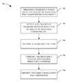
- a method 500 for identifying an objectis illustrated.
- a scan for SARA RFID tagsis undertaken.
- SARA RFID tagsare designed to operate in accordance with SARA protocols, and therefore may transmit over frequencies that are not conventionally used by RFID tags.
- a list of detected tagsis prepared, wherein the list is prepared based upon detected frequencies of the SARA RFID tags.
- An example listis (1 f1, 1 f2, 1 f3, 1 f4, 1 f5, 1 f6).
- a list of potential objectsis constructed, wherein the potential objects have a threshold amount of similarity with respect to frequencies of SARA RFID tags.
- a list of identified objectsis constructed based upon context.
- the contextmay indicate that Object 1 is the object identified.
- a method 600 for identifying an objectis illustrated.
- a frequency over which an RFID tag communicatesis detected.
- a frequencycan be indicative of an identity of an RFID tag.
- the objectis identified based at least in part upon the detected frequency.
- a method 700 for identifying an objectis illustrated.
- a frequency sweepis performed over a plurality of RFID tags that correspond to an object.
- a plurality of frequencies over which the plurality of RFID tags communicateare detected, and at 706 a frequency pattern is prepared.
- the frequency patternis compared with known frequency patterns.
- the objectis identified based upon the comparison.
- functions performed by one or more of the modules described abovecan be realized by executing instructions in a computer-readable medium.
- a processormay access a computer-readable medium and execute instructions therein to detect frequencies used by RFID tags, generate frequency patterns, and compare frequency patterns with known frequency patterns.
Landscapes
- Engineering & Computer Science (AREA)
- Physics & Mathematics (AREA)
- General Physics & Mathematics (AREA)
- Theoretical Computer Science (AREA)
- Health & Medical Sciences (AREA)
- Computer Networks & Wireless Communication (AREA)
- Toxicology (AREA)
- Microelectronics & Electronic Packaging (AREA)
- Computer Hardware Design (AREA)
- Electromagnetism (AREA)
- General Health & Medical Sciences (AREA)
- Artificial Intelligence (AREA)
- Computer Vision & Pattern Recognition (AREA)
- Near-Field Transmission Systems (AREA)
Abstract
Description
- 1f1; 2f2; 1f3; 2f4; 1f5
The above frequency pattern indicates that one RFID tag was found to be transmitting at a first frequency, two RFID tags were found to be transmitting at a second frequency, one RFID tag was found to be transmitting at a third frequency, two RFID tags were found to be transmitting at a fourth frequency, and one RFID tag was found to be transmitting at a fifth frequency. While shown as solely including detected frequencies and numbers of RFID tags, it is to be understood that thefrequency pattern generator 116 can generate a pattern that includes frequencies detected as well as content and/or unique identity of one or more RFID tags.
- 1f1; 2f2; 1f3; 2f4; 1f5
Claims (15)
Priority Applications (1)
| Application Number | Priority Date | Filing Date | Title |
|---|---|---|---|
| US12/747,548US9818053B2 (en) | 2007-12-19 | 2008-12-09 | Identification of objects using frequency characteristics of RFID tags |
Applications Claiming Priority (3)
| Application Number | Priority Date | Filing Date | Title |
|---|---|---|---|
| US1497007P | 2007-12-19 | 2007-12-19 | |
| US12/747,548US9818053B2 (en) | 2007-12-19 | 2008-12-09 | Identification of objects using frequency characteristics of RFID tags |
| PCT/IB2008/055182WO2009081303A1 (en) | 2007-12-19 | 2008-12-09 | Identification of objects using frequency characteristics of rfid tags |
Publications (2)
| Publication Number | Publication Date |
|---|---|
| US20110133903A1 US20110133903A1 (en) | 2011-06-09 |
| US9818053B2true US9818053B2 (en) | 2017-11-14 |
Family
ID=40473400
Family Applications (1)
| Application Number | Title | Priority Date | Filing Date |
|---|---|---|---|
| US12/747,548Active2032-10-01US9818053B2 (en) | 2007-12-19 | 2008-12-09 | Identification of objects using frequency characteristics of RFID tags |
Country Status (8)
| Country | Link |
|---|---|
| US (1) | US9818053B2 (en) |
| EP (1) | EP2225702B1 (en) |
| JP (1) | JP5498397B2 (en) |
| CN (1) | CN101903894A (en) |
| BR (1) | BRPI0821198A2 (en) |
| DK (1) | DK2225702T3 (en) |
| ES (1) | ES2555208T3 (en) |
| WO (1) | WO2009081303A1 (en) |
Cited By (2)
| Publication number | Priority date | Publication date | Assignee | Title |
|---|---|---|---|---|
| US20210012171A1 (en)* | 2018-03-13 | 2021-01-14 | University Of Louisville | Frequency selective surfaces for tracking, labeling and identification |
| US12062757B2 (en) | 2019-07-01 | 2024-08-13 | A123 Systems Llc | Systems and methods for a composite solid-state battery cell with an ionically conductive polymer electrolyte |
Families Citing this family (16)
| Publication number | Priority date | Publication date | Assignee | Title |
|---|---|---|---|---|
| US9361568B2 (en) | 2005-12-09 | 2016-06-07 | Tego, Inc. | Radio frequency identification tag with hardened memory system |
| US9418263B2 (en) | 2005-12-09 | 2016-08-16 | Tego, Inc. | Operating systems for an RFID tag |
| US9542577B2 (en)* | 2005-12-09 | 2017-01-10 | Tego, Inc. | Information RFID tagging facilities |
| US8451070B2 (en)* | 2010-09-09 | 2013-05-28 | Raytheon Company | Self-powered microelectromechanical oscillator |
| US8115623B1 (en) | 2011-03-28 | 2012-02-14 | Robert M Green | Method and system for hand basket theft detection |
| US8094026B1 (en) | 2011-05-02 | 2012-01-10 | Robert M Green | Organized retail crime detection security system and method |
| WO2013052937A1 (en) | 2011-10-06 | 2013-04-11 | Nant Holdings Ip, Llc | Healthcare object recognition systems and methods |
| US20140327520A1 (en)* | 2013-05-02 | 2014-11-06 | Infineon Technologies Ag | Radio identification arrangement and method for indicating the position of a physical object |
| US9358405B2 (en) | 2013-12-02 | 2016-06-07 | Elektra Ab (Publ) | Controlling access to radiotherapy systems |
| US9953193B2 (en) | 2014-09-30 | 2018-04-24 | Tego, Inc. | Operating systems for an RFID tag |
| CN104939992B (en)* | 2015-06-05 | 2017-06-27 | 上海市浦东新区人民医院 | An Intelligent Mobile System for Radiological Examination of Critically Ill Patients |
| JP6032327B2 (en)* | 2015-06-24 | 2016-11-24 | カシオ計算機株式会社 | Terminal device and program |
| CN106404807A (en)* | 2016-11-08 | 2017-02-15 | 邦达诚科技(常州)有限公司 | Work monitoring system of diagnostic machine and monitoring method thereof |
| WO2018165146A1 (en) | 2017-03-06 | 2018-09-13 | Cummins Filtration Ip, Inc. | Genuine filter recognition with filter monitoring system |
| DK3640853T3 (en)* | 2017-06-14 | 2022-05-09 | Shinetsu Polymer Co | RF MARK HAND TOOLS AND PROCEDURE FOR ATTACHING RF MARKS ON HAND TOOLS |
| CN114680653B (en)* | 2020-12-31 | 2024-06-21 | 广东美的厨房电器制造有限公司 | Cooking utensils |
Citations (34)
| Publication number | Priority date | Publication date | Assignee | Title |
|---|---|---|---|---|
| JPS5478097A (en) | 1977-12-05 | 1979-06-21 | Nippon Koushiyuuha Kk | Packaged article radio wave identifying system |
| JPS6310293A (en) | 1986-07-01 | 1988-01-16 | Mitsubishi Electric Corp | Contactless identification information reader |
| US5119070A (en)* | 1989-01-25 | 1992-06-02 | Tokai Metals Co., Ltd. | Resonant tag |
| US5786764A (en)* | 1995-06-07 | 1998-07-28 | Engellenner; Thomas J. | Voice activated electronic locating systems |
| JPH11174149A (en) | 1997-12-12 | 1999-07-02 | Katsuhiko Osumi | Device for recognizing person to be nursed |
| DE19802975A1 (en)* | 1998-01-22 | 1999-07-29 | Sensor Technos Co Ltd | Retrieving information from LC resonance tag to discriminate counterfeit articles |
| JP2000049655A (en) | 1998-07-28 | 2000-02-18 | Kobayashi Musen Kk | Automatic frequency identification system for lc resonance tag |
| US6127928A (en)* | 1998-02-10 | 2000-10-03 | E-Tag Systems, Inc. | Method and apparatus for locating and tracking documents and other objects |
| US20020145036A1 (en)* | 2001-04-04 | 2002-10-10 | Otto Jerome A. | Radio frequency identification system and method |
| US20030197612A1 (en)* | 2002-03-26 | 2003-10-23 | Kabushiki Kaisha Toshiba | Method of and computer program product for monitoring person's movements |
| GB2390511A (en) | 2002-07-05 | 2004-01-07 | Iain Douglas Cameron | Locating items using frequencies of radio tags |
| US20040066281A1 (en)* | 2002-10-02 | 2004-04-08 | Hughes Michael A. | System and method to identify multiple RFID tags |
| US20040066279A1 (en)* | 2002-10-02 | 2004-04-08 | Hughes Michael A. | RFID system and method including tag ID compression |
| US20040075560A1 (en)* | 2002-10-09 | 2004-04-22 | Rf Saw Components, Incorporated | Transfer function system for determining an identifier on a surface acoustic wave identification tag and method of operating the same |
| JP2004198139A (en) | 2002-12-16 | 2004-07-15 | Aruze Corp | Object identification device |
| JP2004205451A (en) | 2002-12-26 | 2004-07-22 | Aruze Corp | Object recognition device |
| US20040155106A1 (en)* | 2002-11-15 | 2004-08-12 | Schmidtberg Rupert A. | Methods and apparatus for communicating condition information associated with an item |
| US20050278776A1 (en) | 2004-06-10 | 2005-12-15 | Kenji Kitagawa | Personal authentication system |
| CN1711564A (en) | 2002-11-15 | 2005-12-21 | 信得有限公司 | RF identification tag for communicating condition information associated with an item |
| WO2006005148A2 (en) | 2004-07-08 | 2006-01-19 | Itautec Philco S/A - Grupo Itautec Philco | System and method for automatic detection of associations among objects |
| WO2006048806A1 (en) | 2004-11-03 | 2006-05-11 | Koninklijke Philips Electronics N.V. | Configuring spectrum agile devices by means of labels storing spektrum opportunity parameters |
| US20060220856A1 (en)* | 2005-04-01 | 2006-10-05 | Cisco Technology, Inc. | Dynamic and hybrid RFID |
| US20060238307A1 (en)* | 2002-01-09 | 2006-10-26 | Bauer Donald G | Intelligent station using multiple RF antennae and inventory control system and method incorporating same |
| US20060250253A1 (en)* | 2005-03-29 | 2006-11-09 | Zhong-Min Liu | RFID conveyor system and method |
| US20060267731A1 (en)* | 2005-05-31 | 2006-11-30 | Chen Thomas C H | System and apparatus of Internet-linked RFID sensor network for object identifying, sensing, monitoring, tracking and networking |
| US20060290473A1 (en) | 2005-06-27 | 2006-12-28 | Honeywell International Inc. | ID tags with Frequency diversity |
| WO2007000740A1 (en) | 2005-06-28 | 2007-01-04 | Koninklijke Philips Electronics, N.V. | System and method for opportunistic spectrum-sharing by spectrum agile radios (sara) |
| US20070030116A1 (en) | 2005-08-03 | 2007-02-08 | Kamilo Feher | Multimode communication system |
| US20070129983A1 (en) | 2005-12-01 | 2007-06-07 | Siemens Medical Solutions Health Services Corporation | Task and Workflow Management System for Healthcare and other Applications |
| JP2008182573A (en)* | 2007-01-25 | 2008-08-07 | Matsushita Electric Works Ltd | Radio authentication system, and entry/exit control system using the same |
| US20090279725A1 (en)* | 2008-05-07 | 2009-11-12 | Garmin International, Inc. | Radio with hearing loss compensation |
| US20100225454A1 (en)* | 2009-03-03 | 2010-09-09 | Fujitsu Limited | Wireless tag control method, wireless tag, and wireless tag control program |
| US20100316334A1 (en)* | 2007-10-15 | 2010-12-16 | Dr. Anthony Kewitsch | Scalable and modular automated fiber optic cross-connect systems |
| US8979756B2 (en) | 2005-05-06 | 2015-03-17 | Koninklijke Philips N.V. | Wireless medical monitoring device |
- 2008
- 2008-12-09DKDK08865872.9Tpatent/DK2225702T3/enactive
- 2008-12-09ESES08865872.9Tpatent/ES2555208T3/enactiveActive
- 2008-12-09JPJP2010538972Apatent/JP5498397B2/ennot_activeExpired - Fee Related
- 2008-12-09BRBRPI0821198-1Apatent/BRPI0821198A2/ennot_activeApplication Discontinuation
- 2008-12-09WOPCT/IB2008/055182patent/WO2009081303A1/enactiveApplication Filing
- 2008-12-09USUS12/747,548patent/US9818053B2/enactiveActive
- 2008-12-09CNCN2008801211002Apatent/CN101903894A/enactivePending
- 2008-12-09EPEP08865872.9Apatent/EP2225702B1/enactiveActive
Patent Citations (36)
| Publication number | Priority date | Publication date | Assignee | Title |
|---|---|---|---|---|
| JPS5478097A (en) | 1977-12-05 | 1979-06-21 | Nippon Koushiyuuha Kk | Packaged article radio wave identifying system |
| JPS6310293A (en) | 1986-07-01 | 1988-01-16 | Mitsubishi Electric Corp | Contactless identification information reader |
| US5119070A (en)* | 1989-01-25 | 1992-06-02 | Tokai Metals Co., Ltd. | Resonant tag |
| US5786764A (en)* | 1995-06-07 | 1998-07-28 | Engellenner; Thomas J. | Voice activated electronic locating systems |
| JPH11174149A (en) | 1997-12-12 | 1999-07-02 | Katsuhiko Osumi | Device for recognizing person to be nursed |
| DE19802975A1 (en)* | 1998-01-22 | 1999-07-29 | Sensor Technos Co Ltd | Retrieving information from LC resonance tag to discriminate counterfeit articles |
| US6094133A (en)* | 1998-01-22 | 2000-07-25 | Sensor Technos Co., Ltd. | Method of displaying information by using an LC resonance tag |
| US6127928A (en)* | 1998-02-10 | 2000-10-03 | E-Tag Systems, Inc. | Method and apparatus for locating and tracking documents and other objects |
| JP2000049655A (en) | 1998-07-28 | 2000-02-18 | Kobayashi Musen Kk | Automatic frequency identification system for lc resonance tag |
| US20020145036A1 (en)* | 2001-04-04 | 2002-10-10 | Otto Jerome A. | Radio frequency identification system and method |
| US20060238307A1 (en)* | 2002-01-09 | 2006-10-26 | Bauer Donald G | Intelligent station using multiple RF antennae and inventory control system and method incorporating same |
| US20030197612A1 (en)* | 2002-03-26 | 2003-10-23 | Kabushiki Kaisha Toshiba | Method of and computer program product for monitoring person's movements |
| GB2390511A (en) | 2002-07-05 | 2004-01-07 | Iain Douglas Cameron | Locating items using frequencies of radio tags |
| US20040066281A1 (en)* | 2002-10-02 | 2004-04-08 | Hughes Michael A. | System and method to identify multiple RFID tags |
| US20040066279A1 (en)* | 2002-10-02 | 2004-04-08 | Hughes Michael A. | RFID system and method including tag ID compression |
| US20040075560A1 (en)* | 2002-10-09 | 2004-04-22 | Rf Saw Components, Incorporated | Transfer function system for determining an identifier on a surface acoustic wave identification tag and method of operating the same |
| US20040155106A1 (en)* | 2002-11-15 | 2004-08-12 | Schmidtberg Rupert A. | Methods and apparatus for communicating condition information associated with an item |
| CN1711564A (en) | 2002-11-15 | 2005-12-21 | 信得有限公司 | RF identification tag for communicating condition information associated with an item |
| US7091861B2 (en) | 2002-11-15 | 2006-08-15 | Sensitech Inc. | RF identification tag for communicating condition information associated with an item |
| JP2004198139A (en) | 2002-12-16 | 2004-07-15 | Aruze Corp | Object identification device |
| JP2004205451A (en) | 2002-12-26 | 2004-07-22 | Aruze Corp | Object recognition device |
| US20050278776A1 (en) | 2004-06-10 | 2005-12-15 | Kenji Kitagawa | Personal authentication system |
| WO2006005148A2 (en) | 2004-07-08 | 2006-01-19 | Itautec Philco S/A - Grupo Itautec Philco | System and method for automatic detection of associations among objects |
| WO2006048806A1 (en) | 2004-11-03 | 2006-05-11 | Koninklijke Philips Electronics N.V. | Configuring spectrum agile devices by means of labels storing spektrum opportunity parameters |
| US20060250253A1 (en)* | 2005-03-29 | 2006-11-09 | Zhong-Min Liu | RFID conveyor system and method |
| US20060220856A1 (en)* | 2005-04-01 | 2006-10-05 | Cisco Technology, Inc. | Dynamic and hybrid RFID |
| US8979756B2 (en) | 2005-05-06 | 2015-03-17 | Koninklijke Philips N.V. | Wireless medical monitoring device |
| US20060267731A1 (en)* | 2005-05-31 | 2006-11-30 | Chen Thomas C H | System and apparatus of Internet-linked RFID sensor network for object identifying, sensing, monitoring, tracking and networking |
| US20060290473A1 (en) | 2005-06-27 | 2006-12-28 | Honeywell International Inc. | ID tags with Frequency diversity |
| WO2007000740A1 (en) | 2005-06-28 | 2007-01-04 | Koninklijke Philips Electronics, N.V. | System and method for opportunistic spectrum-sharing by spectrum agile radios (sara) |
| US20070030116A1 (en) | 2005-08-03 | 2007-02-08 | Kamilo Feher | Multimode communication system |
| US20070129983A1 (en) | 2005-12-01 | 2007-06-07 | Siemens Medical Solutions Health Services Corporation | Task and Workflow Management System for Healthcare and other Applications |
| JP2008182573A (en)* | 2007-01-25 | 2008-08-07 | Matsushita Electric Works Ltd | Radio authentication system, and entry/exit control system using the same |
| US20100316334A1 (en)* | 2007-10-15 | 2010-12-16 | Dr. Anthony Kewitsch | Scalable and modular automated fiber optic cross-connect systems |
| US20090279725A1 (en)* | 2008-05-07 | 2009-11-12 | Garmin International, Inc. | Radio with hearing loss compensation |
| US20100225454A1 (en)* | 2009-03-03 | 2010-09-09 | Fujitsu Limited | Wireless tag control method, wireless tag, and wireless tag control program |
Non-Patent Citations (1)
| Title |
|---|
| English Translation of Japanese Document: JP2004198139; Published on Jul. 15, 2004; Translated on Mar. 3, 2014.* |
Cited By (3)
| Publication number | Priority date | Publication date | Assignee | Title |
|---|---|---|---|---|
| US20210012171A1 (en)* | 2018-03-13 | 2021-01-14 | University Of Louisville | Frequency selective surfaces for tracking, labeling and identification |
| US11687753B2 (en)* | 2018-03-13 | 2023-06-27 | University Of Louisville | Frequency selective surfaces for tracking, labeling and identification |
| US12062757B2 (en) | 2019-07-01 | 2024-08-13 | A123 Systems Llc | Systems and methods for a composite solid-state battery cell with an ionically conductive polymer electrolyte |
Also Published As
| Publication number | Publication date |
|---|---|
| CN101903894A (en) | 2010-12-01 |
| EP2225702B1 (en) | 2015-10-21 |
| WO2009081303A1 (en) | 2009-07-02 |
| JP5498397B2 (en) | 2014-05-21 |
| US20110133903A1 (en) | 2011-06-09 |
| ES2555208T3 (en) | 2015-12-29 |
| EP2225702A1 (en) | 2010-09-08 |
| BRPI0821198A2 (en) | 2015-06-16 |
| JP2011508300A (en) | 2011-03-10 |
| DK2225702T3 (en) | 2015-12-14 |
Similar Documents
| Publication | Publication Date | Title |
|---|---|---|
| US9818053B2 (en) | Identification of objects using frequency characteristics of RFID tags | |
| US10248817B2 (en) | Reading RFID tags in defined spatial locations | |
| US8217793B2 (en) | Rogue RFID detector | |
| EP2208390B1 (en) | Methods and systems of sharing power in a multiple radio frequency network node rfid tag | |
| US7489242B2 (en) | RFID multiple range method and system | |
| US7423516B2 (en) | Systems and methods for approximating the location of an RFID tag | |
| EP1958172B1 (en) | Multiple radio frequency network node rfid tag | |
| US20050088304A1 (en) | Mobile RFID management method and system | |
| US20180025313A1 (en) | System, methods and device for tracking surgical sponges | |
| US20090138303A1 (en) | Activity Inference And Reactive Feedback | |
| Camacho-Cogollo et al. | RFID technology in health care | |
| US20130088354A1 (en) | System, Method and Device for Tracking Surgical Sponges | |
| US11334728B2 (en) | Interrogator and interrogation system employing the same | |
| US20120313757A1 (en) | Interrogator and Interrogation System Employing the Same | |
| US20230084032A1 (en) | Systems and methods for localizing retained surgical items combining rfid tags and computer vision | |
| WO2010150031A1 (en) | System for locating and registration of mobile units moving in zones defined by access points | |
| Pappu et al. | RFID in hospitals: Issues and Solutions | |
| US9396425B1 (en) | Systems and methods for locating objects using RFID technology and alerting mechanisms | |
| Azmi et al. | Radio frequency identification (RFID) range test for animal activity monitoring | |
| US20230094991A1 (en) | System, Device, Product, Apparatus, and Method for Reading Syringe Information | |
| Porter et al. | Effect of active interference on the performance of radio frequency identification systems | |
| Cheng et al. | Accurate location tracking based on active RFID for health and safety monitoring | |
| US20240238047A1 (en) | Inventory systems and methods for retained surgical item detection | |
| Hosaka et al. | Experimental trial to detect medical engineering equipments in hospital by passive UHF RFID tag | |
| Littman | Implementing RFID technology in hospital environments |
Legal Events
| Date | Code | Title | Description |
|---|---|---|---|
| AS | Assignment | Owner name:KONINKLIJKE PHILIPS ELECTRONICS N. V., NETHERLANDS Free format text:ASSIGNMENT OF ASSIGNORS INTEREST;ASSIGNOR:ALSAFADI, YASSER;REEL/FRAME:025802/0648 Effective date:20110211 | |
| STCF | Information on status: patent grant | Free format text:PATENTED CASE | |
| MAFP | Maintenance fee payment | Free format text:PAYMENT OF MAINTENANCE FEE, 4TH YEAR, LARGE ENTITY (ORIGINAL EVENT CODE: M1551); ENTITY STATUS OF PATENT OWNER: LARGE ENTITY Year of fee payment:4 | |
| AS | Assignment | Owner name:KONINKLIJKE PHILIPS N.V., NETHERLANDS Free format text:CHANGE OF NAME;ASSIGNOR:KONINKLIJKE PHILIPS ELECTRONICS N.V.;REEL/FRAME:062559/0328 Effective date:20130515 | |
| AS | Assignment | Owner name:BEIJING XIAOMI MOBILE SOFTWARE CO., LTD., CHINA Free format text:ASSIGNMENT OF ASSIGNORS INTEREST;ASSIGNOR:KONINKLIJKE PHILIPS N.V.;REEL/FRAME:062796/0545 Effective date:20220503 | |
| MAFP | Maintenance fee payment | Free format text:PAYMENT OF MAINTENANCE FEE, 8TH YEAR, LARGE ENTITY (ORIGINAL EVENT CODE: M1552); ENTITY STATUS OF PATENT OWNER: LARGE ENTITY Year of fee payment:8 |