US9816350B2 - Delayed opening pressure actuated ported sub for subterranean use - Google Patents
Delayed opening pressure actuated ported sub for subterranean useDownload PDFInfo
- Publication number
- US9816350B2 US9816350B2US14/270,045US201414270045AUS9816350B2US 9816350 B2US9816350 B2US 9816350B2US 201414270045 AUS201414270045 AUS 201414270045AUS 9816350 B2US9816350 B2US 9816350B2
- Authority
- US
- United States
- Prior art keywords
- pressure
- housing
- assembly
- plug
- rupture disc
- Prior art date
- Legal status (The legal status is an assumption and is not a legal conclusion. Google has not performed a legal analysis and makes no representation as to the accuracy of the status listed.)
- Active, expires
Links
Images


Classifications
- E—FIXED CONSTRUCTIONS
- E21—EARTH OR ROCK DRILLING; MINING
- E21B—EARTH OR ROCK DRILLING; OBTAINING OIL, GAS, WATER, SOLUBLE OR MELTABLE MATERIALS OR A SLURRY OF MINERALS FROM WELLS
- E21B34/00—Valve arrangements for boreholes or wells
- E21B34/06—Valve arrangements for boreholes or wells in wells
- E21B34/10—Valve arrangements for boreholes or wells in wells operated by control fluid supplied from outside the borehole
- E21B34/108—Valve arrangements for boreholes or wells in wells operated by control fluid supplied from outside the borehole with time delay systems, e.g. hydraulic impedance mechanisms
- E—FIXED CONSTRUCTIONS
- E21—EARTH OR ROCK DRILLING; MINING
- E21B—EARTH OR ROCK DRILLING; OBTAINING OIL, GAS, WATER, SOLUBLE OR MELTABLE MATERIALS OR A SLURRY OF MINERALS FROM WELLS
- E21B34/00—Valve arrangements for boreholes or wells
- E21B34/06—Valve arrangements for boreholes or wells in wells
- E21B34/063—Valve or closure with destructible element, e.g. frangible disc
- E—FIXED CONSTRUCTIONS
- E21—EARTH OR ROCK DRILLING; MINING
- E21B—EARTH OR ROCK DRILLING; OBTAINING OIL, GAS, WATER, SOLUBLE OR MELTABLE MATERIALS OR A SLURRY OF MINERALS FROM WELLS
- E21B34/00—Valve arrangements for boreholes or wells
- E21B34/06—Valve arrangements for boreholes or wells in wells
- E21B34/12—Valve arrangements for boreholes or wells in wells operated by movement of casings or tubings
- E21B34/125—Valve arrangements for boreholes or wells in wells operated by movement of casings or tubings with time delay systems, e.g. hydraulic impedance mechanisms
- E21B2034/007—
- E—FIXED CONSTRUCTIONS
- E21—EARTH OR ROCK DRILLING; MINING
- E21B—EARTH OR ROCK DRILLING; OBTAINING OIL, GAS, WATER, SOLUBLE OR MELTABLE MATERIALS OR A SLURRY OF MINERALS FROM WELLS
- E21B2200/00—Special features related to earth drilling for obtaining oil, gas or water
- E21B2200/06—Sleeve valves
- E—FIXED CONSTRUCTIONS
- E21—EARTH OR ROCK DRILLING; MINING
- E21B—EARTH OR ROCK DRILLING; OBTAINING OIL, GAS, WATER, SOLUBLE OR MELTABLE MATERIALS OR A SLURRY OF MINERALS FROM WELLS
- E21B2200/00—Special features related to earth drilling for obtaining oil, gas or water
- E21B2200/08—Down-hole devices using materials which decompose under well-bore conditions
Definitions
- the field of the inventionis pressure operated ported subs opened with sleeve movement and more particularly where the sleeve is actuated with a delay to allow a pressure test of a string followed by sleeve actuation at a far lower pressure than the string test pressure.
- Timers and signal devicesadd complexity and expense and the present invention accomplishes a time delay economically and reliably.
- a disintegrating plugis first exposed to well fluids during the pressure test of the string. After a time the plug disintegrates sufficiently to allow tubing pressure access to a second rupture disc mounted in a pressure balanced chamber. Then when it is desired to shift the sleeve the second rupture disc is deliberately broken at a lower pressure level than the test pressure to allow entry of tubing pressure to a piston that is referenced to a low pressure such as atmospheric. The large differential pressure on the piston then shifts the sleeve.
- the opening of the portsprovides formation access for a variety of operations such as fracturing, acidizing, injecting or conditioning.
- a ported subis operated with a pressure actuated shifting sleeve.
- a first rupture discis set at a lower pressure than the test pressure for the tubing string that houses the ported sub.
- the first rupture discbreaks at a lower pressure than the string test pressure to expose well fluids to a disintegrating plug.
- the plugdisintegrates over time to then expose tubing pressure to a chamber and a second rupture disc with the chamber configured to have no effect on moving the sliding sleeve.
- the second discbreaks exposing a piston to tubing pressure on one side and trapped low pressure being the opposite side of the string.
- the differentialmoves the sleeve to open a port to let tools be pumped into position without a need to perforate.
- FIG. 1is a section view of the pressure actuated sliding sleeve ported sub
- FIG. 1 ais a closer view of the rupture discs and plug of FIG. 1 ;
- FIG. 2is a section view of the first rupture disc
- FIG. 3is a section view of the disintegrating plug between rupture discs
- FIG. 4is a section view of the second rupture disc
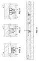
- FIG. 5is the view of FIG. 1 with tubing pressure applied
- FIG. 6is the view of FIG. 5 with the first rupture disc broken during a pressure test of the string
- FIG. 7is the view of FIG. 6 with the disintegrating plug compromised
- FIG. 8is a shifted view of the sliding sleeve of FIG. 1 ;
- FIG. 8 ais a closer view of parts of the sliding sleeve of FIG. 8 .
- the housing 10has end connections 12 and 14 to connect to a tubular string that is not shown.
- Housing 10has ports 16 that are initially closed by sleeve 18 with seals 20 and 22 straddling ports 16 .
- a low pressure variable volume chamber 24is defined between sleeve 18 and housing 10 as well as seals 26 and 28 .
- Seal 26is on housing 10 and seal 28 moves with sleeve 18 .
- a first rupture disc 30is set for a pressure below the intended test pressure for the tubular string that is connected at end connections 12 and 14 .
- Behind rupture disc 30is a variable volume chamber 32 defined by the housing 10 , the sleeve 18 , seal 28 and seal 34 that are both mounted to the sleeve 18 .
- a disintegrating plug 35initially isolates chamber 32 from passage 36 that leads to the second rupture disc 38 .
- Variable volume chamber 40is defined by housing 10 , sleeve 18 , seal 34 and seal 42 . Seal 34 and seal 42 are on the sleeve 18 .
- Chamber 24is at low or atmospheric pressure.
- FIG. 5The pressure is built up to the tubing string test pressure which is higher than the burst pressure of the first rupture disc 30 .
- the rupture disc 30breaks to allow tubing fluid 44 into chamber 32 .
- Sleeve 18is in force balance from pressure migrating into chamber 32 so it still does not move.
- the tubing pressureis raised to the desired string test pressure with the first rupture disc now broken.
- the pressure testis designed to end before the plug 35 is undermined. This allows the tubing pressure to be lowered first before the disintegration of plug 35 can open passage 36 .
- FIG. 7shows the plug has been undermined to open passage 36 to tubing fluid 44 .
- An application of the pressure operated sleeveis in a cemented casing where circulation needs to be established to allow pumping down equipment particularly in a horizontal portion of a borehole. Perforation is not needed to open up such a circulation path.
- the pressure actuated sleevecan be placed just above a cement shoe so that pressure can be built up to the string test pressure and on the way to that pressure the first rupture disc breaks and starts the clock in a sense on the disintegration of the plug.
- the plugcan be made of different materials depending on the time needed to conduct the pressure test to conclusion and then reduce the tubing pressure.
- One such materialis a controlled electrolytic material (CEM) that has been described in US Publication 2011/0136707 and related applications filed the same day.
Landscapes
- Life Sciences & Earth Sciences (AREA)
- Engineering & Computer Science (AREA)
- Geology (AREA)
- Mining & Mineral Resources (AREA)
- Physics & Mathematics (AREA)
- Environmental & Geological Engineering (AREA)
- Fluid Mechanics (AREA)
- General Life Sciences & Earth Sciences (AREA)
- Geochemistry & Mineralogy (AREA)
- Investigating Strength Of Materials By Application Of Mechanical Stress (AREA)
Abstract
Description
Claims (24)
Priority Applications (1)
| Application Number | Priority Date | Filing Date | Title |
|---|---|---|---|
| US14/270,045US9816350B2 (en) | 2014-05-05 | 2014-05-05 | Delayed opening pressure actuated ported sub for subterranean use |
Applications Claiming Priority (1)
| Application Number | Priority Date | Filing Date | Title |
|---|---|---|---|
| US14/270,045US9816350B2 (en) | 2014-05-05 | 2014-05-05 | Delayed opening pressure actuated ported sub for subterranean use |
Publications (2)
| Publication Number | Publication Date |
|---|---|
| US20150315873A1 US20150315873A1 (en) | 2015-11-05 |
| US9816350B2true US9816350B2 (en) | 2017-11-14 |
Family
ID=54354900
Family Applications (1)
| Application Number | Title | Priority Date | Filing Date |
|---|---|---|---|
| US14/270,045Active2035-12-02US9816350B2 (en) | 2014-05-05 | 2014-05-05 | Delayed opening pressure actuated ported sub for subterranean use |
Country Status (1)
| Country | Link |
|---|---|
| US (1) | US9816350B2 (en) |
Cited By (14)
| Publication number | Priority date | Publication date | Assignee | Title |
|---|---|---|---|---|
| US20180334882A1 (en)* | 2017-05-19 | 2018-11-22 | Frac Technology AS | Downhole tool |
| CN108956326A (en)* | 2018-07-20 | 2018-12-07 | 四川省劲腾环保建材有限公司 | A kind of method and device detecting solid brick flexural strength |
| US10294755B2 (en) | 2012-04-27 | 2019-05-21 | Tejas Research & Engineering, Llc | Dual barrier injection valve with a variable orifice |
| US10378312B2 (en) | 2012-04-27 | 2019-08-13 | Tejas Research & Engineering, Llc | Tubing retrievable injection valve assembly |
| CN110566159A (en)* | 2019-09-23 | 2019-12-13 | 中国石油集团川庆钻探工程有限公司 | oil-gas well fracturing transformation process adopting time-delay opening toe end sliding sleeve |
| WO2020021353A1 (en) | 2018-07-25 | 2020-01-30 | Downhole Products Limited | Overpressure toe valve with atmospheric chamber |
| US10619452B1 (en)* | 2019-07-31 | 2020-04-14 | Vertice Oil Tools | Methods and systems for creating an interventionless conduit to formation in wells with cased hole |
| US10704361B2 (en) | 2012-04-27 | 2020-07-07 | Tejas Research & Engineering, Llc | Method and apparatus for injecting fluid into spaced injection zones in an oil/gas well |
| WO2021144632A1 (en) | 2020-01-14 | 2021-07-22 | Downhole Products Limited | Toe valve with vented atmospheric chamber |
| US11268347B2 (en)* | 2017-07-24 | 2022-03-08 | National Oilwell Varco, L.P. | Testable sliding sleeve valve |
| US11454087B2 (en) | 2018-09-25 | 2022-09-27 | Advanced Upstream Ltd. | Delayed opening port assembly |
| US11939836B2 (en) | 2020-08-31 | 2024-03-26 | Advanced Upstream Ltd. | Port sub with delayed opening sequence |
| US20240167360A1 (en)* | 2020-10-14 | 2024-05-23 | John Tyler Thomason | Payload deployment tools and methods of using same |
| US12123281B2 (en) | 2022-03-18 | 2024-10-22 | Torsch Inc. | Barrier member |
Families Citing this family (9)
| Publication number | Priority date | Publication date | Assignee | Title |
|---|---|---|---|---|
| US9598931B2 (en)* | 2014-06-24 | 2017-03-21 | Halliburton Energy Services Inc. | Multi-acting downhole tool arrangement |
| CA2918299C (en)* | 2015-01-21 | 2023-11-21 | Trican Completion Solutions Ltd | Burst port sub with dissolvable barrier |
| US10036229B2 (en)* | 2015-02-13 | 2018-07-31 | Weatherford Technology Holdings, Llc | Time delay toe sleeve |
| US10060213B2 (en)* | 2015-10-14 | 2018-08-28 | Baker Hughes, A Ge Company, Llc | Residual pressure differential removal mechanism for a setting device for a subterranean tool |
| US10337285B2 (en)* | 2016-12-12 | 2019-07-02 | Innovex Downhole Solutions, Inc. | Time-delayed downhole tool |
| CN109296348B (en)* | 2018-10-31 | 2023-09-15 | 中国石油集团川庆钻探工程有限公司 | Toe end sliding sleeve capable of being opened in time delay mode |
| WO2020117229A1 (en)* | 2018-12-05 | 2020-06-11 | Halliburton Energy Services, Inc. | Downhole apparatus |
| US12129738B2 (en) | 2021-01-20 | 2024-10-29 | Schlumberger Technology Corporation | Multicycle valve system |
| GB2615099A (en)* | 2022-01-27 | 2023-08-02 | Hill Radtke Cameron | A pressure testable toe sleeve and a method for pressure testing a wellbore |
Citations (76)
| Publication number | Priority date | Publication date | Assignee | Title |
|---|---|---|---|---|
| US3189044A (en) | 1959-04-21 | 1965-06-15 | Phillip S Sizer | Pressure differential operated safety valve |
| US3442328A (en) | 1967-12-11 | 1969-05-06 | Schlumberger Technology Corp | Well tool valve actuators |
| US3570594A (en) | 1969-03-13 | 1971-03-16 | Howell M Hamilton | Subsurface control apparatus for use in oil and gas wells |
| US3662834A (en) | 1970-06-03 | 1972-05-16 | Schlumberger Technology Corp | Methods and apparatus for completing production wells |
| US3896667A (en) | 1973-10-26 | 1975-07-29 | Texas Dynamatics | Method and apparatus for actuating downhole devices |
| US3930540A (en) | 1972-09-11 | 1976-01-06 | Halliburton Company | Wellbore circulating valve |
| US3964544A (en) | 1975-06-20 | 1976-06-22 | Halliburton Company | Pressure operated isolation valve for use in a well testing and treating apparatus, and its method of operation |
| US3986554A (en) | 1975-05-21 | 1976-10-19 | Schlumberger Technology Corporation | Pressure controlled reversing valve |
| US4109724A (en) | 1977-10-27 | 1978-08-29 | Halliburton Company | Oil well testing valve with liquid spring |
| US4257484A (en) | 1980-03-10 | 1981-03-24 | Whitley Oran D | Pressure differential circulating valve |
| US4330039A (en) | 1980-07-07 | 1982-05-18 | Geo Vann, Inc. | Pressure actuated vent assembly for slanted wellbores |
| US4403659A (en) | 1981-04-13 | 1983-09-13 | Schlumberger Technology Corporation | Pressure controlled reversing valve |
| US4434854A (en) | 1980-07-07 | 1984-03-06 | Geo Vann, Inc. | Pressure actuated vent assembly for slanted wellbores |
| US4691779A (en) | 1986-01-17 | 1987-09-08 | Halliburton Company | Hydrostatic referenced safety-circulating valve |
| US4718494A (en) | 1985-12-30 | 1988-01-12 | Schlumberger Technology Corporation | Methods and apparatus for selectively controlling fluid communication between a pipe string and a well bore annulus |
| US4970655A (en) | 1988-11-01 | 1990-11-13 | American Registration Systems, Inc. | Automatic fee collecting and receipt dispensing system |
| US4979569A (en) | 1989-07-06 | 1990-12-25 | Schlumberger Technology Corporation | Dual action valve including at least two pressure responsive members |
| US4991654A (en) | 1989-11-08 | 1991-02-12 | Halliburton Company | Casing valve |
| US5044444A (en) | 1989-04-28 | 1991-09-03 | Baker Hughes Incorporated | Method and apparatus for chemical treatment of subterranean well bores |
| US5325917A (en) | 1991-10-21 | 1994-07-05 | Halliburton Company | Short stroke casing valve with positioning and jetting tools therefor |
| US5355959A (en) | 1992-09-22 | 1994-10-18 | Halliburton Company | Differential pressure operated circulating and deflation valve |
| US5425424A (en)* | 1994-02-28 | 1995-06-20 | Baker Hughes Incorporated | Casing valve |
| US5649597A (en) | 1995-07-14 | 1997-07-22 | Halliburton Company | Differential pressure test/bypass valve and method for using the same |
| US5810087A (en) | 1996-01-24 | 1998-09-22 | Schlumberger Technology Corporation | Formation isolation valve adapted for building a tool string of any desired length prior to lowering the tool string downhole for performing a wellbore operation |
| US5819853A (en) | 1995-08-08 | 1998-10-13 | Schlumberger Technology Corporation | Rupture disc operated valves for use in drill stem testing |
| US5840087A (en) | 1996-09-18 | 1998-11-24 | Bell Communications Research, Inc. | Method for making laminated rechargeable battery cells |
| US5954135A (en) | 1997-01-17 | 1999-09-21 | Halliburton Energy Services, Inc. | Method and apparatus for establishing fluid communication within a subterranean well |
| US6035880A (en) | 1997-05-01 | 2000-03-14 | Halliburton Energy Services, Inc. | Pressure activated switch valve |
| US6186227B1 (en) | 1999-04-21 | 2001-02-13 | Schlumberger Technology Corporation | Packer |
| US6286594B1 (en) | 1997-10-09 | 2001-09-11 | Ocre (Scotland) Limited | Downhole valve |
| US6293346B1 (en) | 1998-09-21 | 2001-09-25 | Schlumberger Technology Corporation | Method and apparatus for relieving pressure |
| US6308783B2 (en) | 1996-04-26 | 2001-10-30 | Schlumberger Technology Corporation | Wellbore flow control device |
| US6386289B1 (en) | 1998-02-12 | 2002-05-14 | Schlumberger Technology Corporation | Reclosable circulating valve for well completion systems |
| US6470970B1 (en) | 1998-08-13 | 2002-10-29 | Welldynamics Inc. | Multiplier digital-hydraulic well control system and method |
| US6550541B2 (en) | 2000-05-12 | 2003-04-22 | Schlumberger Technology Corporation | Valve assembly |
| US6604583B1 (en) | 1998-03-19 | 2003-08-12 | International Construction Equipment B.V. | Vibrating device and a method for driving an object by vibration |
| US6659186B2 (en) | 2000-05-12 | 2003-12-09 | Schlumberger Technology Corporation | Valve assembly |
| US6684950B2 (en) | 2001-03-01 | 2004-02-03 | Schlumberger Technology Corporation | System for pressure testing tubing |
| US20040045724A1 (en) | 2000-11-03 | 2004-03-11 | Mark Buyers | Hydraulic setting tool with pressure multiplier |
| US6722469B1 (en) | 2002-06-14 | 2004-04-20 | Kenneth F. Weger, Jr. | Guard plate and safety anchor |
| US6945331B2 (en) | 2002-07-31 | 2005-09-20 | Schlumberger Technology Corporation | Multiple interventionless actuated downhole valve and method |
| US6948561B2 (en) | 2002-07-12 | 2005-09-27 | Baker Hughes Incorporated | Indexing apparatus |
| US20080066923A1 (en) | 2006-09-18 | 2008-03-20 | Baker Hughes Incorporated | Dissolvable downhole trigger device |
| US20090071642A1 (en) | 2005-07-22 | 2009-03-19 | Baker Hughes Incorporated | Downhole trigger apparatus |
| US7562713B2 (en) | 2006-02-21 | 2009-07-21 | Schlumberger Technology Corporation | Downhole actuation tools |
| WO2009105128A1 (en) | 2008-02-20 | 2009-08-27 | Baker Hughes Incorporated | Downhole trigger apparatus |
| US7640988B2 (en) | 2005-03-18 | 2010-01-05 | Exxon Mobil Upstream Research Company | Hydraulically controlled burst disk subs and methods for their use |
| US7703510B2 (en) | 2007-08-27 | 2010-04-27 | Baker Hughes Incorporated | Interventionless multi-position frac tool |
| US7762324B2 (en) | 2007-12-04 | 2010-07-27 | Baker Hughes Incorporated | Bypass crossover sub selector for multi-zone fracturing processes |
| US20100200243A1 (en) | 2007-10-19 | 2010-08-12 | Daniel Purkis | Method and device |
| US20100236781A1 (en) | 2009-03-20 | 2010-09-23 | Integrated Production Services Ltd. | Method and apparatus for perforating multiple wellbore intervals |
| US7841412B2 (en) | 2007-02-21 | 2010-11-30 | Baker Hughes Incorporated | Multi-purpose pressure operated downhole valve |
| US7845416B2 (en) | 2005-11-11 | 2010-12-07 | Bj Services Company | Hydraulic sleeve valve with position indication, alignment, and bypass |
| US20100314562A1 (en)* | 2009-06-10 | 2010-12-16 | Baker Hughes Incorporated | Delay activated valve and method |
| US20110056679A1 (en) | 2009-09-09 | 2011-03-10 | Schlumberger Technology Corporation | System and method for controlling actuation of downhole tools |
| US7909095B2 (en) | 2008-10-07 | 2011-03-22 | Halliburton Energy Services, Inc. | Valve device and associated methods of selectively communicating between an interior and an exterior of a tubular string |
| US7913770B2 (en) | 2008-06-30 | 2011-03-29 | Baker Hughes Incorporated | Controlled pressure equalization of atmospheric chambers |
| US20110100643A1 (en) | 2008-04-29 | 2011-05-05 | Packers Plus Energy Services Inc. | Downhole sub with hydraulically actuable sleeve valve |
| US20110114324A1 (en) | 2009-11-13 | 2011-05-19 | Baker Hughes Incorporated | Modular hydraulic operator for a subterranean tool |
| US20110278017A1 (en) | 2009-05-07 | 2011-11-17 | Packers Plus Energy Services Inc. | Sliding sleeve sub and method and apparatus for wellbore fluid treatment |
| US20120006553A1 (en) | 2010-07-07 | 2012-01-12 | Baker Hughes Incorporated | Injection Valve with Indexing Mechanism |
| US20120048559A1 (en) | 2010-08-31 | 2012-03-01 | Schlumberger Technology Corporation | Methods for completing multi-zone production wells using sliding sleeve valve assembly |
| US8171994B2 (en) | 2007-08-16 | 2012-05-08 | Baker Hughes Incorporated | Multi-position valve for fracturing and sand control and associated completion methods |
| US20120138311A1 (en) | 2010-11-01 | 2012-06-07 | Oiltool Engineering Services, Inc. | Method and Apparatus for Single-Trip Time Progressive Wellbore Treatment |
| US20120186803A1 (en) | 2011-01-21 | 2012-07-26 | Baker Hughes Incorporated | Combined Fracturing Outlet and Production Port for a Tubular String |
| US20120211242A1 (en) | 2011-02-21 | 2012-08-23 | Patel Dinesh R | Multi-stage valve actuator |
| US8267178B1 (en)* | 2011-09-01 | 2012-09-18 | Team Oil Tools, Lp | Valve for hydraulic fracturing through cement outside casing |
| US8276670B2 (en) | 2009-04-27 | 2012-10-02 | Schlumberger Technology Corporation | Downhole dissolvable plug |
| US20120267119A1 (en) | 2011-04-22 | 2012-10-25 | Patel Dinesh R | Interventionless operation of downhole tool |
| US20120279723A1 (en)* | 2011-05-02 | 2012-11-08 | Peak Completion Technologies, Inc. | Downhole Tool |
| US20120285702A1 (en) | 2011-05-11 | 2012-11-15 | Schlumberger Technology Corporation | System and method for actuating tools downhole |
| US20130062124A1 (en) | 2011-09-09 | 2013-03-14 | Baker Hughes Incorporated | Drilling Apparatus Including a Fluid Bypass Device and Methods of Using Same |
| US8555960B2 (en) | 2011-07-29 | 2013-10-15 | Baker Hughes Incorporated | Pressure actuated ported sub for subterranean cement completions |
| US20140102703A1 (en) | 2012-10-15 | 2014-04-17 | Baker Hughes Incorporated | Pressure Actuated Ported Sub for Subterranean Cement Completions |
| US20140251620A1 (en)* | 2013-03-07 | 2014-09-11 | Kevin R. George | Method and Apparatus for Establishing Injection into a Cased Bore Hole using a Time Delay Toe Injection Apparatus |
| US20160237781A1 (en)* | 2015-02-13 | 2016-08-18 | Weatherford Technology Holdings, Llc | Time Delay Toe Sleeve |
- 2014
- 2014-05-05USUS14/270,045patent/US9816350B2/enactiveActive
Patent Citations (79)
| Publication number | Priority date | Publication date | Assignee | Title |
|---|---|---|---|---|
| US3189044A (en) | 1959-04-21 | 1965-06-15 | Phillip S Sizer | Pressure differential operated safety valve |
| US3442328A (en) | 1967-12-11 | 1969-05-06 | Schlumberger Technology Corp | Well tool valve actuators |
| US3570594A (en) | 1969-03-13 | 1971-03-16 | Howell M Hamilton | Subsurface control apparatus for use in oil and gas wells |
| US3662834A (en) | 1970-06-03 | 1972-05-16 | Schlumberger Technology Corp | Methods and apparatus for completing production wells |
| US3930540A (en) | 1972-09-11 | 1976-01-06 | Halliburton Company | Wellbore circulating valve |
| US3896667A (en) | 1973-10-26 | 1975-07-29 | Texas Dynamatics | Method and apparatus for actuating downhole devices |
| US3986554A (en) | 1975-05-21 | 1976-10-19 | Schlumberger Technology Corporation | Pressure controlled reversing valve |
| US3964544A (en) | 1975-06-20 | 1976-06-22 | Halliburton Company | Pressure operated isolation valve for use in a well testing and treating apparatus, and its method of operation |
| US4109724A (en) | 1977-10-27 | 1978-08-29 | Halliburton Company | Oil well testing valve with liquid spring |
| US4257484A (en) | 1980-03-10 | 1981-03-24 | Whitley Oran D | Pressure differential circulating valve |
| US4330039A (en) | 1980-07-07 | 1982-05-18 | Geo Vann, Inc. | Pressure actuated vent assembly for slanted wellbores |
| US4434854A (en) | 1980-07-07 | 1984-03-06 | Geo Vann, Inc. | Pressure actuated vent assembly for slanted wellbores |
| US4403659A (en) | 1981-04-13 | 1983-09-13 | Schlumberger Technology Corporation | Pressure controlled reversing valve |
| US4718494A (en) | 1985-12-30 | 1988-01-12 | Schlumberger Technology Corporation | Methods and apparatus for selectively controlling fluid communication between a pipe string and a well bore annulus |
| US4691779A (en) | 1986-01-17 | 1987-09-08 | Halliburton Company | Hydrostatic referenced safety-circulating valve |
| US4970655A (en) | 1988-11-01 | 1990-11-13 | American Registration Systems, Inc. | Automatic fee collecting and receipt dispensing system |
| US5044444A (en) | 1989-04-28 | 1991-09-03 | Baker Hughes Incorporated | Method and apparatus for chemical treatment of subterranean well bores |
| US4979569A (en) | 1989-07-06 | 1990-12-25 | Schlumberger Technology Corporation | Dual action valve including at least two pressure responsive members |
| US4991654A (en) | 1989-11-08 | 1991-02-12 | Halliburton Company | Casing valve |
| US5325917A (en) | 1991-10-21 | 1994-07-05 | Halliburton Company | Short stroke casing valve with positioning and jetting tools therefor |
| US5355959A (en) | 1992-09-22 | 1994-10-18 | Halliburton Company | Differential pressure operated circulating and deflation valve |
| US5425424A (en)* | 1994-02-28 | 1995-06-20 | Baker Hughes Incorporated | Casing valve |
| US5649597A (en) | 1995-07-14 | 1997-07-22 | Halliburton Company | Differential pressure test/bypass valve and method for using the same |
| US5819853A (en) | 1995-08-08 | 1998-10-13 | Schlumberger Technology Corporation | Rupture disc operated valves for use in drill stem testing |
| US5950733A (en) | 1996-01-24 | 1999-09-14 | Schlumberger Technology Corporation | Formation isolation valve |
| US5810087A (en) | 1996-01-24 | 1998-09-22 | Schlumberger Technology Corporation | Formation isolation valve adapted for building a tool string of any desired length prior to lowering the tool string downhole for performing a wellbore operation |
| US6308783B2 (en) | 1996-04-26 | 2001-10-30 | Schlumberger Technology Corporation | Wellbore flow control device |
| US5840087A (en) | 1996-09-18 | 1998-11-24 | Bell Communications Research, Inc. | Method for making laminated rechargeable battery cells |
| US5954135A (en) | 1997-01-17 | 1999-09-21 | Halliburton Energy Services, Inc. | Method and apparatus for establishing fluid communication within a subterranean well |
| US6035880A (en) | 1997-05-01 | 2000-03-14 | Halliburton Energy Services, Inc. | Pressure activated switch valve |
| US6286594B1 (en) | 1997-10-09 | 2001-09-11 | Ocre (Scotland) Limited | Downhole valve |
| US6386289B1 (en) | 1998-02-12 | 2002-05-14 | Schlumberger Technology Corporation | Reclosable circulating valve for well completion systems |
| US6604583B1 (en) | 1998-03-19 | 2003-08-12 | International Construction Equipment B.V. | Vibrating device and a method for driving an object by vibration |
| US6470970B1 (en) | 1998-08-13 | 2002-10-29 | Welldynamics Inc. | Multiplier digital-hydraulic well control system and method |
| US6293346B1 (en) | 1998-09-21 | 2001-09-25 | Schlumberger Technology Corporation | Method and apparatus for relieving pressure |
| US6186227B1 (en) | 1999-04-21 | 2001-02-13 | Schlumberger Technology Corporation | Packer |
| US6550541B2 (en) | 2000-05-12 | 2003-04-22 | Schlumberger Technology Corporation | Valve assembly |
| US6659186B2 (en) | 2000-05-12 | 2003-12-09 | Schlumberger Technology Corporation | Valve assembly |
| US20040045724A1 (en) | 2000-11-03 | 2004-03-11 | Mark Buyers | Hydraulic setting tool with pressure multiplier |
| US6684950B2 (en) | 2001-03-01 | 2004-02-03 | Schlumberger Technology Corporation | System for pressure testing tubing |
| US6722469B1 (en) | 2002-06-14 | 2004-04-20 | Kenneth F. Weger, Jr. | Guard plate and safety anchor |
| US6948561B2 (en) | 2002-07-12 | 2005-09-27 | Baker Hughes Incorporated | Indexing apparatus |
| US6945331B2 (en) | 2002-07-31 | 2005-09-20 | Schlumberger Technology Corporation | Multiple interventionless actuated downhole valve and method |
| US7640988B2 (en) | 2005-03-18 | 2010-01-05 | Exxon Mobil Upstream Research Company | Hydraulically controlled burst disk subs and methods for their use |
| US20090071642A1 (en) | 2005-07-22 | 2009-03-19 | Baker Hughes Incorporated | Downhole trigger apparatus |
| US7845416B2 (en) | 2005-11-11 | 2010-12-07 | Bj Services Company | Hydraulic sleeve valve with position indication, alignment, and bypass |
| US7562713B2 (en) | 2006-02-21 | 2009-07-21 | Schlumberger Technology Corporation | Downhole actuation tools |
| US20080066923A1 (en) | 2006-09-18 | 2008-03-20 | Baker Hughes Incorporated | Dissolvable downhole trigger device |
| US7841412B2 (en) | 2007-02-21 | 2010-11-30 | Baker Hughes Incorporated | Multi-purpose pressure operated downhole valve |
| US8171994B2 (en) | 2007-08-16 | 2012-05-08 | Baker Hughes Incorporated | Multi-position valve for fracturing and sand control and associated completion methods |
| US7703510B2 (en) | 2007-08-27 | 2010-04-27 | Baker Hughes Incorporated | Interventionless multi-position frac tool |
| US20100200243A1 (en) | 2007-10-19 | 2010-08-12 | Daniel Purkis | Method and device |
| US7762324B2 (en) | 2007-12-04 | 2010-07-27 | Baker Hughes Incorporated | Bypass crossover sub selector for multi-zone fracturing processes |
| WO2009105128A1 (en) | 2008-02-20 | 2009-08-27 | Baker Hughes Incorporated | Downhole trigger apparatus |
| US20110100643A1 (en) | 2008-04-29 | 2011-05-05 | Packers Plus Energy Services Inc. | Downhole sub with hydraulically actuable sleeve valve |
| US7913770B2 (en) | 2008-06-30 | 2011-03-29 | Baker Hughes Incorporated | Controlled pressure equalization of atmospheric chambers |
| US7909095B2 (en) | 2008-10-07 | 2011-03-22 | Halliburton Energy Services, Inc. | Valve device and associated methods of selectively communicating between an interior and an exterior of a tubular string |
| US20100236781A1 (en) | 2009-03-20 | 2010-09-23 | Integrated Production Services Ltd. | Method and apparatus for perforating multiple wellbore intervals |
| US8276670B2 (en) | 2009-04-27 | 2012-10-02 | Schlumberger Technology Corporation | Downhole dissolvable plug |
| US20110278017A1 (en) | 2009-05-07 | 2011-11-17 | Packers Plus Energy Services Inc. | Sliding sleeve sub and method and apparatus for wellbore fluid treatment |
| US20100314562A1 (en)* | 2009-06-10 | 2010-12-16 | Baker Hughes Incorporated | Delay activated valve and method |
| US20110056679A1 (en) | 2009-09-09 | 2011-03-10 | Schlumberger Technology Corporation | System and method for controlling actuation of downhole tools |
| US20110114324A1 (en) | 2009-11-13 | 2011-05-19 | Baker Hughes Incorporated | Modular hydraulic operator for a subterranean tool |
| US20120006553A1 (en) | 2010-07-07 | 2012-01-12 | Baker Hughes Incorporated | Injection Valve with Indexing Mechanism |
| US20120048559A1 (en) | 2010-08-31 | 2012-03-01 | Schlumberger Technology Corporation | Methods for completing multi-zone production wells using sliding sleeve valve assembly |
| US20120138311A1 (en) | 2010-11-01 | 2012-06-07 | Oiltool Engineering Services, Inc. | Method and Apparatus for Single-Trip Time Progressive Wellbore Treatment |
| US20120186803A1 (en) | 2011-01-21 | 2012-07-26 | Baker Hughes Incorporated | Combined Fracturing Outlet and Production Port for a Tubular String |
| WO2012115868A2 (en) | 2011-02-21 | 2012-08-30 | Schlumberger Canada Limited | Multi-stage valve actuator |
| US20120211242A1 (en) | 2011-02-21 | 2012-08-23 | Patel Dinesh R | Multi-stage valve actuator |
| WO2012145735A1 (en) | 2011-04-22 | 2012-10-26 | Schlumberger Canada Limited | Interventionless operation of downhole tool |
| US20120267119A1 (en) | 2011-04-22 | 2012-10-25 | Patel Dinesh R | Interventionless operation of downhole tool |
| US20120279723A1 (en)* | 2011-05-02 | 2012-11-08 | Peak Completion Technologies, Inc. | Downhole Tool |
| US20120285702A1 (en) | 2011-05-11 | 2012-11-15 | Schlumberger Technology Corporation | System and method for actuating tools downhole |
| US8555960B2 (en) | 2011-07-29 | 2013-10-15 | Baker Hughes Incorporated | Pressure actuated ported sub for subterranean cement completions |
| US8267178B1 (en)* | 2011-09-01 | 2012-09-18 | Team Oil Tools, Lp | Valve for hydraulic fracturing through cement outside casing |
| US20130062124A1 (en) | 2011-09-09 | 2013-03-14 | Baker Hughes Incorporated | Drilling Apparatus Including a Fluid Bypass Device and Methods of Using Same |
| US20140102703A1 (en) | 2012-10-15 | 2014-04-17 | Baker Hughes Incorporated | Pressure Actuated Ported Sub for Subterranean Cement Completions |
| US20140251620A1 (en)* | 2013-03-07 | 2014-09-11 | Kevin R. George | Method and Apparatus for Establishing Injection into a Cased Bore Hole using a Time Delay Toe Injection Apparatus |
| US20160237781A1 (en)* | 2015-02-13 | 2016-08-18 | Weatherford Technology Holdings, Llc | Time Delay Toe Sleeve |
Non-Patent Citations (3)
| Title |
|---|
| Delta Stim Initiator Valve Drawing, HAL24633, Date unknown, 1 page. |
| McCoy, J.N., et al., "Timer Control of Beam Pump Run Time Reduces Operating Expense", Presented at the Forty-Sixth Annual Southwestern Petroleum Short Course in Lubbock, Texas, Apr. 21-22, 1999, 16 pages. |
| Schlumberger, KickStart Rupture Disc Valve, Date unknown, 1 page. |
Cited By (18)
| Publication number | Priority date | Publication date | Assignee | Title |
|---|---|---|---|---|
| US10704361B2 (en) | 2012-04-27 | 2020-07-07 | Tejas Research & Engineering, Llc | Method and apparatus for injecting fluid into spaced injection zones in an oil/gas well |
| US10294755B2 (en) | 2012-04-27 | 2019-05-21 | Tejas Research & Engineering, Llc | Dual barrier injection valve with a variable orifice |
| US10378312B2 (en) | 2012-04-27 | 2019-08-13 | Tejas Research & Engineering, Llc | Tubing retrievable injection valve assembly |
| US20180334882A1 (en)* | 2017-05-19 | 2018-11-22 | Frac Technology AS | Downhole tool |
| US10787884B2 (en)* | 2017-05-19 | 2020-09-29 | Frac Technology AS | Downhole tool having a dissolvable plug |
| US11268347B2 (en)* | 2017-07-24 | 2022-03-08 | National Oilwell Varco, L.P. | Testable sliding sleeve valve |
| CN108956326A (en)* | 2018-07-20 | 2018-12-07 | 四川省劲腾环保建材有限公司 | A kind of method and device detecting solid brick flexural strength |
| US11428073B2 (en) | 2018-07-25 | 2022-08-30 | Downhole Products Limited | Overpressure toe valve with atmospheric chamber |
| WO2020021353A1 (en) | 2018-07-25 | 2020-01-30 | Downhole Products Limited | Overpressure toe valve with atmospheric chamber |
| US11454087B2 (en) | 2018-09-25 | 2022-09-27 | Advanced Upstream Ltd. | Delayed opening port assembly |
| US10619452B1 (en)* | 2019-07-31 | 2020-04-14 | Vertice Oil Tools | Methods and systems for creating an interventionless conduit to formation in wells with cased hole |
| CN110566159B (en)* | 2019-09-23 | 2021-05-04 | 中国石油集团川庆钻探工程有限公司 | Oil-gas well fracturing transformation process adopting time-delay opening toe end sliding sleeve |
| CN110566159A (en)* | 2019-09-23 | 2019-12-13 | 中国石油集团川庆钻探工程有限公司 | oil-gas well fracturing transformation process adopting time-delay opening toe end sliding sleeve |
| WO2021144632A1 (en) | 2020-01-14 | 2021-07-22 | Downhole Products Limited | Toe valve with vented atmospheric chamber |
| US11920432B2 (en) | 2020-01-14 | 2024-03-05 | Downhole Products Limited | Toe valve with vented atmospheric chamber |
| US11939836B2 (en) | 2020-08-31 | 2024-03-26 | Advanced Upstream Ltd. | Port sub with delayed opening sequence |
| US20240167360A1 (en)* | 2020-10-14 | 2024-05-23 | John Tyler Thomason | Payload deployment tools and methods of using same |
| US12123281B2 (en) | 2022-03-18 | 2024-10-22 | Torsch Inc. | Barrier member |
Also Published As
| Publication number | Publication date |
|---|---|
| US20150315873A1 (en) | 2015-11-05 |
Similar Documents
| Publication | Publication Date | Title |
|---|---|---|
| US9816350B2 (en) | Delayed opening pressure actuated ported sub for subterranean use | |
| US7963342B2 (en) | Downhole isolation valve and methods for use | |
| US10082002B2 (en) | Multi-stage fracturing with smart frack sleeves while leaving a full flow bore | |
| US9441440B2 (en) | Downhole tools, system and method of using | |
| US9441437B2 (en) | Electronic rupture discs for interventionless barrier plug | |
| US9441446B2 (en) | Electronic rupture discs for interventionaless barrier plug | |
| US9121247B2 (en) | Method and apparatus for establishing injection into a cased bore hole using a time delay toe injection apparatus | |
| DK179965B1 (en) | Multi-zone fracturing with full wellbore access | |
| US10036229B2 (en) | Time delay toe sleeve | |
| US20140251620A1 (en) | Method and Apparatus for Establishing Injection into a Cased Bore Hole using a Time Delay Toe Injection Apparatus | |
| US20150337629A1 (en) | Using dynamic underbalance to increase well productivity | |
| US9284801B2 (en) | Actuator switch for a downhole tool, tool and method | |
| US20160298417A1 (en) | System for Resealing Borehole Access | |
| CA2892128C (en) | Method and apparatus for establishing injection into a cased bore hole using a time delay toe injection apparatus | |
| US8684087B1 (en) | Downhole flow control using perforator and membrane | |
| US9404350B2 (en) | Flow-activated flow control device and method of using same in wellbores | |
| GB2433083A (en) | Tool initiation system using motion and pressure sensors | |
| CA2886176C (en) | Downhole flow control using perforator and membrane | |
| WO2024174023A1 (en) | Apparatus for selectively isolating segments of a wellbore |
Legal Events
| Date | Code | Title | Description |
|---|---|---|---|
| AS | Assignment | Owner name:BAKER HUGHES INCORPORATED, TEXAS Free format text:ASSIGNMENT OF ASSIGNORS INTEREST;ASSIGNORS:MAILAND, JASON C.;ELLIOTT, CHRISTOPHER K.;ROBERTS, TYLER C.;SIGNING DATES FROM 20140506 TO 20140519;REEL/FRAME:033308/0094 | |
| AS | Assignment | Owner name:BAKER HUGHES, A GE COMPANY, LLC, TEXAS Free format text:MERGER AND CHANGE OF NAME;ASSIGNORS:BAKER HUGHES INCORPORATED;BAKER HUGHES, A GE COMPANY, LLC;REEL/FRAME:044117/0775 Effective date:20170703 | |
| STCF | Information on status: patent grant | Free format text:PATENTED CASE | |
| MAFP | Maintenance fee payment | Free format text:PAYMENT OF MAINTENANCE FEE, 4TH YEAR, LARGE ENTITY (ORIGINAL EVENT CODE: M1551); ENTITY STATUS OF PATENT OWNER: LARGE ENTITY Year of fee payment:4 | |
| AS | Assignment | Owner name:BAKER HUGHES HOLDINGS LLC, TEXAS Free format text:CHANGE OF NAME;ASSIGNOR:BAKER HUGHES, A GE COMPANY, LLC;REEL/FRAME:061037/0086 Effective date:20200413 | |
| AS | Assignment | Owner name:BAKER HUGHES HOLDINGS LLC, TEXAS Free format text:CHANGE OF NAME;ASSIGNOR:BAKER HUGHES, A GE COMPANY, LLC;REEL/FRAME:060818/0965 Effective date:20200413 | |
| MAFP | Maintenance fee payment | Free format text:PAYMENT OF MAINTENANCE FEE, 8TH YEAR, LARGE ENTITY (ORIGINAL EVENT CODE: M1552); ENTITY STATUS OF PATENT OWNER: LARGE ENTITY Year of fee payment:8 |