US9814862B2 - Reentry catheter and method thereof - Google Patents
Reentry catheter and method thereofDownload PDFInfo
- Publication number
- US9814862B2 US9814862B2US14/128,050US201214128050AUS9814862B2US 9814862 B2US9814862 B2US 9814862B2US 201214128050 AUS201214128050 AUS 201214128050AUS 9814862 B2US9814862 B2US 9814862B2
- Authority
- US
- United States
- Prior art keywords
- catheter
- reentry
- lumen
- port
- cannula
- Prior art date
- Legal status (The legal status is an assumption and is not a legal conclusion. Google has not performed a legal analysis and makes no representation as to the accuracy of the status listed.)
- Active, expires
Links
- 238000000034methodMethods0.000titleclaimsabstractdescription52
- 210000004204blood vesselAnatomy0.000claimsdescription17
- 230000037361pathwayEffects0.000claimsdescription7
- 230000036961partial effectEffects0.000abstractdescription10
- 238000003780insertionMethods0.000abstractdescription5
- 230000037431insertionEffects0.000abstractdescription5
- 239000003550markerSubstances0.000description159
- 239000000463materialSubstances0.000description42
- 238000013459approachMethods0.000description21
- 238000002594fluoroscopyMethods0.000description21
- 238000012800visualizationMethods0.000description19
- 210000001367arteryAnatomy0.000description18
- 230000008901benefitEffects0.000description17
- 238000011282treatmentMethods0.000description14
- 230000035515penetrationEffects0.000description12
- 230000008569processEffects0.000description12
- 210000002435tendonAnatomy0.000description12
- 208000034693LacerationDiseases0.000description11
- 230000007246mechanismEffects0.000description11
- 238000007794visualization techniqueMethods0.000description11
- 238000005520cutting processMethods0.000description10
- 230000000153supplemental effectEffects0.000description10
- HWLDNSXPUQTBOD-UHFFFAOYSA-Nplatinum-iridium alloyChemical compound[Ir].[Pt]HWLDNSXPUQTBOD-UHFFFAOYSA-N0.000description9
- 238000003466weldingMethods0.000description9
- 229920001343polytetrafluoroethylenePolymers0.000description8
- 239000004810polytetrafluoroethyleneSubstances0.000description8
- 229920002614Polyether block amidePolymers0.000description7
- 239000011248coating agentSubstances0.000description7
- 238000000576coating methodMethods0.000description7
- 238000000926separation methodMethods0.000description7
- 239000004642PolyimideSubstances0.000description6
- 239000003292glueSubstances0.000description6
- 229920001721polyimidePolymers0.000description6
- 239000010935stainless steelSubstances0.000description6
- 229910001220stainless steelInorganic materials0.000description6
- 208000027418Wounds and injuryDiseases0.000description5
- 230000003902lesionEffects0.000description5
- 230000033001locomotionEffects0.000description5
- 238000000465mouldingMethods0.000description5
- -1polyethylenePolymers0.000description5
- 238000004804windingMethods0.000description5
- 230000017531blood circulationEffects0.000description4
- 238000010276constructionMethods0.000description4
- 238000002608intravascular ultrasoundMethods0.000description4
- 239000004698PolyethyleneSubstances0.000description3
- 229910045601alloyInorganic materials0.000description3
- 239000000956alloySubstances0.000description3
- 210000003484anatomyAnatomy0.000description3
- 210000002808connective tissueAnatomy0.000description3
- 238000002224dissectionMethods0.000description3
- 238000011068loading methodMethods0.000description3
- 229910052751metalInorganic materials0.000description3
- 239000002184metalSubstances0.000description3
- 229910001000nickel titaniumInorganic materials0.000description3
- HLXZNVUGXRDIFK-UHFFFAOYSA-Nnickel titaniumChemical compound[Ti].[Ti].[Ti].[Ti].[Ti].[Ti].[Ti].[Ti].[Ti].[Ti].[Ti].[Ni].[Ni].[Ni].[Ni].[Ni].[Ni].[Ni].[Ni].[Ni].[Ni].[Ni].[Ni].[Ni].[Ni]HLXZNVUGXRDIFK-UHFFFAOYSA-N0.000description3
- 230000003287optical effectEffects0.000description3
- 229920002647polyamidePolymers0.000description3
- 229920000573polyethylenePolymers0.000description3
- 229920000642polymerPolymers0.000description3
- 230000009467reductionEffects0.000description3
- 230000002792vascularEffects0.000description3
- 229920000271Kevlar®Polymers0.000description2
- 239000004696Poly ether ether ketoneSubstances0.000description2
- 239000004952PolyamideSubstances0.000description2
- 229910000831SteelInorganic materials0.000description2
- 230000005540biological transmissionEffects0.000description2
- 230000002308calcificationEffects0.000description2
- 230000001684chronic effectEffects0.000description2
- 238000007796conventional methodMethods0.000description2
- 230000006378damageEffects0.000description2
- 238000013461designMethods0.000description2
- 230000010339dilationEffects0.000description2
- 230000003073embolic effectEffects0.000description2
- 208000014674injuryDiseases0.000description2
- 238000013152interventional procedureMethods0.000description2
- 239000004761kevlarSubstances0.000description2
- 238000003475laminationMethods0.000description2
- 238000000608laser ablationMethods0.000description2
- 238000004519manufacturing processMethods0.000description2
- 150000002739metalsChemical class0.000description2
- 238000012986modificationMethods0.000description2
- 230000004048modificationEffects0.000description2
- 229920000728polyesterPolymers0.000description2
- 229920002530polyetherether ketonePolymers0.000description2
- 229920000098polyolefinPolymers0.000description2
- 229920002635polyurethanePolymers0.000description2
- 239000004814polyurethaneSubstances0.000description2
- 238000012545processingMethods0.000description2
- 238000007674radiofrequency ablationMethods0.000description2
- 230000002829reductive effectEffects0.000description2
- 230000004044responseEffects0.000description2
- 230000000717retained effectEffects0.000description2
- 239000010959steelSubstances0.000description2
- 239000012815thermoplastic materialSubstances0.000description2
- 239000010409thin filmSubstances0.000description2
- 210000001519tissueAnatomy0.000description2
- 210000005166vasculatureAnatomy0.000description2
- BQCIDUSAKPWEOX-UHFFFAOYSA-N1,1-DifluoroetheneChemical compoundFC(F)=CBQCIDUSAKPWEOX-UHFFFAOYSA-N0.000description1
- 206010003210ArteriosclerosisDiseases0.000description1
- 201000001320AtherosclerosisDiseases0.000description1
- 208000037260Atherosclerotic PlaqueDiseases0.000description1
- 101150082208DIABLO geneProteins0.000description1
- 229920006370KynarPolymers0.000description1
- 239000004677NylonSubstances0.000description1
- 208000005764Peripheral Arterial DiseaseDiseases0.000description1
- 208000030831Peripheral arterial occlusive diseaseDiseases0.000description1
- 206010034576Peripheral ischaemiaDiseases0.000description1
- 239000004721Polyphenylene oxideSubstances0.000description1
- 239000004743PolypropyleneSubstances0.000description1
- RTAQQCXQSZGOHL-UHFFFAOYSA-NTitaniumChemical compound[Ti]RTAQQCXQSZGOHL-UHFFFAOYSA-N0.000description1
- 230000004913activationEffects0.000description1
- 238000006243chemical reactionMethods0.000description1
- 239000003153chemical reaction reagentSubstances0.000description1
- 229920001577copolymerPolymers0.000description1
- 230000008021depositionEffects0.000description1
- 238000006073displacement reactionMethods0.000description1
- 229940079593drugDrugs0.000description1
- 239000003814drugSubstances0.000description1
- 238000012377drug deliveryMethods0.000description1
- 230000000694effectsEffects0.000description1
- 229920001971elastomerPolymers0.000description1
- 239000000806elastomerSubstances0.000description1
- 229920001746electroactive polymerPolymers0.000description1
- 238000011010flushing procedureMethods0.000description1
- 239000002783friction materialSubstances0.000description1
- 230000006870functionEffects0.000description1
- 230000036541healthEffects0.000description1
- 238000007654immersionMethods0.000description1
- 238000010348incorporationMethods0.000description1
- 230000010354integrationEffects0.000description1
- 238000002697interventional radiologyMethods0.000description1
- 238000011542limb amputationMethods0.000description1
- 230000014759maintenance of locationEffects0.000description1
- 238000002483medicationMethods0.000description1
- 208000010125myocardial infarctionDiseases0.000description1
- 229920001778nylonPolymers0.000description1
- 239000013307optical fiberSubstances0.000description1
- 230000000149penetrating effectEffects0.000description1
- 230000002093peripheral effectEffects0.000description1
- 229920000570polyetherPolymers0.000description1
- 229920001155polypropylenePolymers0.000description1
- 230000001681protective effectEffects0.000description1
- 230000002441reversible effectEffects0.000description1
- 239000007787solidSubstances0.000description1
- 239000000126substanceSubstances0.000description1
- 238000013151thrombectomyMethods0.000description1
- 239000010936titaniumSubstances0.000description1
- 229910052719titaniumInorganic materials0.000description1
- 238000012546transferMethods0.000description1
- 230000007704transitionEffects0.000description1
- 238000013519translationMethods0.000description1
- 230000000007visual effectEffects0.000description1
Images


Classifications
- A—HUMAN NECESSITIES
- A61—MEDICAL OR VETERINARY SCIENCE; HYGIENE
- A61M—DEVICES FOR INTRODUCING MEDIA INTO, OR ONTO, THE BODY; DEVICES FOR TRANSDUCING BODY MEDIA OR FOR TAKING MEDIA FROM THE BODY; DEVICES FOR PRODUCING OR ENDING SLEEP OR STUPOR
- A61M25/00—Catheters; Hollow probes
- A61M25/01—Introducing, guiding, advancing, emplacing or holding catheters
- A61M25/0194—Tunnelling catheters
- A—HUMAN NECESSITIES
- A61—MEDICAL OR VETERINARY SCIENCE; HYGIENE
- A61B—DIAGNOSIS; SURGERY; IDENTIFICATION
- A61B17/00—Surgical instruments, devices or methods
- A61B17/34—Trocars; Puncturing needles
- A61B17/3417—Details of tips or shafts, e.g. grooves, expandable, bendable; Multiple coaxial sliding cannulas, e.g. for dilating
- A61B17/3421—Cannulas
- A61B17/3423—Access ports, e.g. toroid shape introducers for instruments or hands
- A—HUMAN NECESSITIES
- A61—MEDICAL OR VETERINARY SCIENCE; HYGIENE
- A61M—DEVICES FOR INTRODUCING MEDIA INTO, OR ONTO, THE BODY; DEVICES FOR TRANSDUCING BODY MEDIA OR FOR TAKING MEDIA FROM THE BODY; DEVICES FOR PRODUCING OR ENDING SLEEP OR STUPOR
- A61M25/00—Catheters; Hollow probes
- A61M25/0021—Catheters; Hollow probes characterised by the form of the tubing
- A61M25/0023—Catheters; Hollow probes characterised by the form of the tubing by the form of the lumen, e.g. cross-section, variable diameter
- A61M25/0026—Multi-lumen catheters with stationary elements
- A61M25/003—Multi-lumen catheters with stationary elements characterized by features relating to least one lumen located at the distal part of the catheter, e.g. filters, plugs or valves
- A—HUMAN NECESSITIES
- A61—MEDICAL OR VETERINARY SCIENCE; HYGIENE
- A61M—DEVICES FOR INTRODUCING MEDIA INTO, OR ONTO, THE BODY; DEVICES FOR TRANSDUCING BODY MEDIA OR FOR TAKING MEDIA FROM THE BODY; DEVICES FOR PRODUCING OR ENDING SLEEP OR STUPOR
- A61M25/00—Catheters; Hollow probes
- A61M25/0067—Catheters; Hollow probes characterised by the distal end, e.g. tips
- A61M25/0074—Dynamic characteristics of the catheter tip, e.g. openable, closable, expandable or deformable
- A—HUMAN NECESSITIES
- A61—MEDICAL OR VETERINARY SCIENCE; HYGIENE
- A61M—DEVICES FOR INTRODUCING MEDIA INTO, OR ONTO, THE BODY; DEVICES FOR TRANSDUCING BODY MEDIA OR FOR TAKING MEDIA FROM THE BODY; DEVICES FOR PRODUCING OR ENDING SLEEP OR STUPOR
- A61M25/00—Catheters; Hollow probes
- A61M25/01—Introducing, guiding, advancing, emplacing or holding catheters
- A61M25/0105—Steering means as part of the catheter or advancing means; Markers for positioning
- A61M25/0108—Steering means as part of the catheter or advancing means; Markers for positioning using radio-opaque or ultrasound markers
- A—HUMAN NECESSITIES
- A61—MEDICAL OR VETERINARY SCIENCE; HYGIENE
- A61M—DEVICES FOR INTRODUCING MEDIA INTO, OR ONTO, THE BODY; DEVICES FOR TRANSDUCING BODY MEDIA OR FOR TAKING MEDIA FROM THE BODY; DEVICES FOR PRODUCING OR ENDING SLEEP OR STUPOR
- A61M25/00—Catheters; Hollow probes
- A61M25/01—Introducing, guiding, advancing, emplacing or holding catheters
- A61M25/0172—Exchanging a guidewire while keeping the catheter in place
- A—HUMAN NECESSITIES
- A61—MEDICAL OR VETERINARY SCIENCE; HYGIENE
- A61B—DIAGNOSIS; SURGERY; IDENTIFICATION
- A61B17/00—Surgical instruments, devices or methods
- A61B17/22—Implements for squeezing-off ulcers or the like on inner organs of the body; Implements for scraping-out cavities of body organs, e.g. bones; for invasive removal or destruction of calculus using mechanical vibrations; for removing obstructions in blood vessels, not otherwise provided for
- A61B2017/22038—Implements for squeezing-off ulcers or the like on inner organs of the body; Implements for scraping-out cavities of body organs, e.g. bones; for invasive removal or destruction of calculus using mechanical vibrations; for removing obstructions in blood vessels, not otherwise provided for with a guide wire
- A61B2017/22042—Details of the tip of the guide wire
- A61B2017/22044—Details of the tip of the guide wire with a pointed tip
- A—HUMAN NECESSITIES
- A61—MEDICAL OR VETERINARY SCIENCE; HYGIENE
- A61B—DIAGNOSIS; SURGERY; IDENTIFICATION
- A61B17/00—Surgical instruments, devices or methods
- A61B17/22—Implements for squeezing-off ulcers or the like on inner organs of the body; Implements for scraping-out cavities of body organs, e.g. bones; for invasive removal or destruction of calculus using mechanical vibrations; for removing obstructions in blood vessels, not otherwise provided for
- A61B2017/22094—Implements for squeezing-off ulcers or the like on inner organs of the body; Implements for scraping-out cavities of body organs, e.g. bones; for invasive removal or destruction of calculus using mechanical vibrations; for removing obstructions in blood vessels, not otherwise provided for for crossing total occlusions, i.e. piercing
- A61B2017/22095—Implements for squeezing-off ulcers or the like on inner organs of the body; Implements for scraping-out cavities of body organs, e.g. bones; for invasive removal or destruction of calculus using mechanical vibrations; for removing obstructions in blood vessels, not otherwise provided for for crossing total occlusions, i.e. piercing accessing a blood vessel true lumen from the sub-intimal space
- A—HUMAN NECESSITIES
- A61—MEDICAL OR VETERINARY SCIENCE; HYGIENE
- A61M—DEVICES FOR INTRODUCING MEDIA INTO, OR ONTO, THE BODY; DEVICES FOR TRANSDUCING BODY MEDIA OR FOR TAKING MEDIA FROM THE BODY; DEVICES FOR PRODUCING OR ENDING SLEEP OR STUPOR
- A61M25/00—Catheters; Hollow probes
- A61M2025/0004—Catheters; Hollow probes having two or more concentrically arranged tubes for forming a concentric catheter system
- A—HUMAN NECESSITIES
- A61—MEDICAL OR VETERINARY SCIENCE; HYGIENE
- A61M—DEVICES FOR INTRODUCING MEDIA INTO, OR ONTO, THE BODY; DEVICES FOR TRANSDUCING BODY MEDIA OR FOR TAKING MEDIA FROM THE BODY; DEVICES FOR PRODUCING OR ENDING SLEEP OR STUPOR
- A61M25/00—Catheters; Hollow probes
- A61M2025/0008—Catheters; Hollow probes having visible markings on its surface, i.e. visible to the naked eye, for any purpose, e.g. insertion depth markers, rotational markers or identification of type
- A—HUMAN NECESSITIES
- A61—MEDICAL OR VETERINARY SCIENCE; HYGIENE
- A61M—DEVICES FOR INTRODUCING MEDIA INTO, OR ONTO, THE BODY; DEVICES FOR TRANSDUCING BODY MEDIA OR FOR TAKING MEDIA FROM THE BODY; DEVICES FOR PRODUCING OR ENDING SLEEP OR STUPOR
- A61M25/00—Catheters; Hollow probes
- A61M25/0021—Catheters; Hollow probes characterised by the form of the tubing
- A61M25/0023—Catheters; Hollow probes characterised by the form of the tubing by the form of the lumen, e.g. cross-section, variable diameter
- A61M25/0026—Multi-lumen catheters with stationary elements
- A61M2025/0037—Multi-lumen catheters with stationary elements characterized by lumina being arranged side-by-side
- A—HUMAN NECESSITIES
- A61—MEDICAL OR VETERINARY SCIENCE; HYGIENE
- A61M—DEVICES FOR INTRODUCING MEDIA INTO, OR ONTO, THE BODY; DEVICES FOR TRANSDUCING BODY MEDIA OR FOR TAKING MEDIA FROM THE BODY; DEVICES FOR PRODUCING OR ENDING SLEEP OR STUPOR
- A61M25/00—Catheters; Hollow probes
- A61M25/0067—Catheters; Hollow probes characterised by the distal end, e.g. tips
- A61M25/0074—Dynamic characteristics of the catheter tip, e.g. openable, closable, expandable or deformable
- A61M2025/0079—Separate user-activated means, e.g. guidewires, guide tubes, balloon catheters or sheaths, for sealing off an orifice, e.g. a lumen or side holes, of a catheter
- A—HUMAN NECESSITIES
- A61—MEDICAL OR VETERINARY SCIENCE; HYGIENE
- A61M—DEVICES FOR INTRODUCING MEDIA INTO, OR ONTO, THE BODY; DEVICES FOR TRANSDUCING BODY MEDIA OR FOR TAKING MEDIA FROM THE BODY; DEVICES FOR PRODUCING OR ENDING SLEEP OR STUPOR
- A61M25/00—Catheters; Hollow probes
- A61M25/01—Introducing, guiding, advancing, emplacing or holding catheters
- A61M2025/018—Catheters having a lateral opening for guiding elongated means lateral to the catheter
- A—HUMAN NECESSITIES
- A61—MEDICAL OR VETERINARY SCIENCE; HYGIENE
- A61M—DEVICES FOR INTRODUCING MEDIA INTO, OR ONTO, THE BODY; DEVICES FOR TRANSDUCING BODY MEDIA OR FOR TAKING MEDIA FROM THE BODY; DEVICES FOR PRODUCING OR ENDING SLEEP OR STUPOR
- A61M25/00—Catheters; Hollow probes
- A61M25/01—Introducing, guiding, advancing, emplacing or holding catheters
- A61M2025/0183—Rapid exchange or monorail catheters
- A—HUMAN NECESSITIES
- A61—MEDICAL OR VETERINARY SCIENCE; HYGIENE
- A61M—DEVICES FOR INTRODUCING MEDIA INTO, OR ONTO, THE BODY; DEVICES FOR TRANSDUCING BODY MEDIA OR FOR TAKING MEDIA FROM THE BODY; DEVICES FOR PRODUCING OR ENDING SLEEP OR STUPOR
- A61M25/00—Catheters; Hollow probes
- A61M25/01—Introducing, guiding, advancing, emplacing or holding catheters
- A61M25/0194—Tunnelling catheters
- A61M2025/0197—Tunnelling catheters for creating an artificial passage within the body, e.g. in order to go around occlusions
- A—HUMAN NECESSITIES
- A61—MEDICAL OR VETERINARY SCIENCE; HYGIENE
- A61M—DEVICES FOR INTRODUCING MEDIA INTO, OR ONTO, THE BODY; DEVICES FOR TRANSDUCING BODY MEDIA OR FOR TAKING MEDIA FROM THE BODY; DEVICES FOR PRODUCING OR ENDING SLEEP OR STUPOR
- A61M25/00—Catheters; Hollow probes
- A61M25/0043—Catheters; Hollow probes characterised by structural features
- A61M25/005—Catheters; Hollow probes characterised by structural features with embedded materials for reinforcement, e.g. wires, coils, braids
- A—HUMAN NECESSITIES
- A61—MEDICAL OR VETERINARY SCIENCE; HYGIENE
- A61M—DEVICES FOR INTRODUCING MEDIA INTO, OR ONTO, THE BODY; DEVICES FOR TRANSDUCING BODY MEDIA OR FOR TAKING MEDIA FROM THE BODY; DEVICES FOR PRODUCING OR ENDING SLEEP OR STUPOR
- A61M25/00—Catheters; Hollow probes
- A61M25/0067—Catheters; Hollow probes characterised by the distal end, e.g. tips
- A61M25/0068—Static characteristics of the catheter tip, e.g. shape, atraumatic tip, curved tip or tip structure
- A61M25/0069—Tip not integral with tube
Definitions
- the inventiongenerally relates to a method and apparatus for crossing an obstruction in a tubular member, and more particularly to a medical device and method for crossing an occlusion or partial occlusion in a subintimal or interstitial space of the vasculature.
- Atherosclerosisis a common human ailment arising from the deposition of a fatty-like substance, such as atheroma, or plaque on the walls of major blood vessels. These deposits occur within the peripheral arterial system which feeds the limbs of the body and also occur within the coronary arterial system which feeds the heart. These deposits accumulate in localized areas, narrow the vascular lumen, and eventually cause restriction of normal blood flow. In some cases, the deposits result in a chronic partial or total occlusion. Such restriction can lead to serious health risks including critical limbischaemia, peripheral arterial disease, and heart attack. If blood flow cannot be adequately restored through surgical or endovascular intervention, the probability of limb amputation and other patient injury increases dramatically.
- the inventionis directed to a medical device and method thereof that substantially obviates one or more of the problems due to limitations and disadvantages of the related art.
- An advantage of the inventionis improved stability of the device when oriented within the blood vessel through minimization of the effect of stored torsional forces within the shaft.
- Another advantage of the inventionis improved stability and control of the distal tip during deployment of the cannula or interventional wire upon reentry from the subintimal space to the vessel lumen thereby preventing the device from backing out or further separating the intima from the adventitia.
- Yet another advantage of the inventionis improved visualization regarding the direction in which the cannula or interventional wire will deploy thereby preventing dissection or other vessel injury upon reentry.
- Another advantage of the inventionis improved tracking and control, thereby allowing a physician or operator to re-enter the vessel lumen at their preferred location close to the distal end of the total occlusion.
- Still another advantage of the inventionis the reduction in the force required to cross the subintimal layer during device reentry into the true vessel lumen due to the articulating cannula or sharp member.
- Yet another advantage of the inventionis the reduction in the overall required size of the device since a long rigid element is not needed at the distal tip to support large reentry forces.
- Still another advantage of the inventionis improved stability and control of the distal tip during deployment of the cannula or interventional wire upon reentry from the subintimal space to the true vessel lumen thereby preventing the device from backing out or further separating the intima from the adventitia.
- Another advantage of the inventionis the reduction in the overall size of the device since a long, permanent distal tip extension is not required to support reentry forces.
- Yet another advantage of the inventionis the reduced tip stiffness profile which provides improved tracking through tortuous anatomy compared to prior art.
- a method for crossing an obstruction in a blood vesselincludes advancing a first wire into an interstitial space of a vessel.
- a rapid exchange catheteris advanced into the subintimal space with the aid of the first wire. That is, the rapid exchange catheter is advanced along the first wire with the aid of the exchange port.
- a second wireis advanced down a central lumen of the rapid exchange catheter and the second wire is advanced through a lateral port of the rapid exchange catheter system into the lumen of the blood vessel.
- reentry into the lumen of a vesselis accomplished at a location immediately distal to the total occlusion.
- a cannulais configured to exit the lateral port and into the true lumen of the vessel from the subintimal space prior to the second wire being advanced through the lateral port.
- a cannulaneed not be utilized.
- a catheter systemthat includes a catheter having a proximal end, a distal end, lateral port, and a first lumen configured to receive a first wire.
- the first lumenextends longitudinally through at least the lateral port of the catheter.
- the catheteralso includes a second lumen having a portion extending distally of the lateral port and also extending through at least the distal end of the catheter.
- the first and second lumensare discontinuous with each other.
- the catheterfurther includes an exchange port, e.g., an RX port, arranged along an exterior portion of the catheter body and configured to receive a second wire.
- the RX portpermits the second wire to extend through the RX port and through the second lumen out the distal end of the catheter.
- the reentry catheterincludes a catheter body having a proximal end, a distal end, at least one lumen, and at least one lateral port.
- An exchange portis arranged on at least a distal portion of the catheter body, the exchange port includes at least one lumen configured to receive a guidewire and the catheter body is configured to track over the guidewire to a treatment site.
- a rotating reentry cutteris arranged near the distal end of the catheter with a pivot point coupled to a rigid distal catheter portion and at least one sharp leading edge.
- the distal end of the rotating reentry cutteris configured to deploy through at least one lateral port of the catheter from a first stowed position to a second deployed position with a leading edge of the rotating reentry cutter positioned to penetrate the interstitial space of an artery.
- a tether, coil, linkage or other suitable control mechanismis coupled to a portion of the rotating reentry cutter to apply an eccentric force which subsequently causes the rotating reentry cutter to rotate from a first stowed position to a second deployed position.
- Application of an opposite eccentric loadcauses the rotary reentry cutter to return from the extended or deployed position to a fully retracted position within the rigid distal portion.
- the reentry catheteris designed to be utilized with a conventional guidewire and/or a conventional guidewire with a micro-support catheter.
- the reentry cathetercan include an internal ramp or wedge, or the like, to guide the crossing support catheter or guidewire out a distal port or out the lateral port from a first position within the subintimal space to a second position within the vessel true lumen.
- the curvature of the rotating reentry cuttercan be used as a deflecting guide to direct the reentry crossing guidewire from a first position within the subintimal space, through the lateral port, along the curvature of the cutter, through the laceration zone created by the cutter, and into a second position within the vessel true lumen.
- the wirecan be retained in a channel, retaining rings, or the like along the outer most distal edge of the rotating reentry device when it is in a deployed position to serve as a guide to direct the wire through the laceration created by the rotating reentry cutter.
- Another embodiment of the inventionis directed towards a method of crossing an obstruction in a blood vessel with a reentry catheter in a subintimal space of a vessel.
- the methodincludes advancing a first guidewire into a lumen of the vessel towards the obstruction in the vessel. Advancing the first guidewire into the subintimal space of the vessel to a location distal of the obstruction and advancing a catheter comprising a rotating reentry cutter over the guidewire to a location where a port of the catheter is at a location distal of the obstruction.
- the reentry cathetermay be advanced in an over the guidewire configuration through a lumen of the catheter body or via an exchange port.
- the methodfurther includes application of an eccentric force to the rotating reentry cutter which rotates the sharp edge from a protective stowed position to a second deployed position such that the sharp leading edge penetrates at least partially through the subintimal vessel layers.
- Actuation of the deployment forcemay be performed through a handle control actuation mechanism near the proximal end of the device as known in the art.
- a push or pull forceis applied to the reentry catheter causing the sharp edge of the rotating reentry cutter to lacerate the subintimal layers of the vessel.
- the lacerationcan be controlled by controls, as known in the art, such that the catheter moves proximally a controlled or fixed distance.
- a wire, internal support catheter, or interventional deviceis then deployed through either a distal port or through the lateral port from within the subintimal space of the vessel to a second location within a true lumen of the vessel.
- the methodmay include returning the rotary reentry cutter from the second location to the first location and removing the reentry catheter and support catheter, if using, from the vessel.
- a second wire or the original wire in an over the wire configurationis advanced down a central lumen of a reentry cannula that is configured to deploy through at least one port created by the separation of the distal portion of the catheter to gain access to a vessel true lumen from a subintimal space.
- the operatoractivates the reentry cannula through either a push or pull mechanism which subsequently either extends a split portion of the distal tip of the catheter distally or retracts a second split portion of the distal tip proximally to provide stability in both the lateral and axial directions upon reaction to the penetration force of cannula re-entry into the vessel true lumen.
- reentry into the true lumen of a vesselis accomplished at a location immediately distal to the total occlusion. It is noted that other locations may also be used for reentry. This embodiment provides for a longer distal extension than is present in currently available in the related art.
- the reentry cannulais configured to exit the at least one port created by the separation of the distal portion of the catheter and cross into the true lumen of the vessel from the subintimal space prior to advancement of an intervention wire through the distal port.
- a catheter systemthat includes a catheter having a proximal end, a distal end, a split catheter distal tip, at least one lumen, and at least one port exposed upon separation of the split catheter distal tip. At least one lumen extends longitudinally through the at least one lateral port of the catheter.
- the catheterincludes a reentry cannula which is configured to gain access to a vessel true lumen from a subintimal space.
- the reentry cannulais configured to penetrate the vessel layers adjacent to the at least one lateral port.
- the reentry cannulais configured to have a hollow portion to receive a supplemental treatment device, such as, an interventional guide wire.
- the reentry catheterincludes a catheter body including a proximal end, a distal end, at least one lumen, and at least one port.
- An exchange portis arranged on at least a distal portion of the catheter body and the exchange port includes at least one lumen configured to receive a guidewire and the catheter body is configured to track over the guidewire to a treatment site.
- a reentry cannulais slidably arranged within the lumen of the catheter body and is configured to deploy through the catheter body port created upon separation of at least one portion of the distal portion of the elongated catheter.
- the reentry cannulais configured to deploy from a first location within the interstitial space of an artery to a second location within a true lumen of the artery upon application of a push or pull control force at a proximal portion the reentry cannula.
- Still yet another aspect of the inventionis directed towards a reentry catheter for use in forming a pathway in an interstitial space of an artery.
- the reentry catheterincludes a catheter body having a proximal end, a distal end, at least one lumen, and at least one port.
- An exchange portis arranged on at least a distal portion of the catheter body. The exchange port is configured to receive a guidewire and the catheter body is configured to track over the guidewire to a treatment site.
- a reentry cannulahaving a proximal end, a distal end, at least one lumen is configured to be slidably positioned within the lumen of the catheter body.
- the reentry catheterincludes a distal portion configured to slidably separate along the catheter longitudinal axis to provide lateral and axial stability and control to counteract forces realized upon penetration of the reentry cannula through the subintimal vessel layers. Further, the separation of the distal portion of catheter creates an at least one port.
- the reentry cannulais configured to deploy through the at least one port from a first location within the interstitial space of an artery to a second location within a true lumen of the artery upon application of a force to the tether.
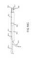
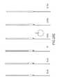
- FIG. 1illustrates an exemplary side view of a reentry catheter according to an embodiment of the invention
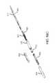
- FIG. 2illustrates an exemplary perspective view of the reentry catheter shown in FIG. 1 ;
- FIG. 3illustrates an exemplary internal view of the reentry catheter shown in FIG. 1 ;
- FIG. 4illustrates an exemplary end view of the reentry catheter shown in FIG. 1 ;
- FIG. 5illustrates an exemplary end view of a reentry catheter according to another embodiment of the invention
- FIG. 6illustrates an exemplary end view of a reentry catheter according to another embodiment of the invention.
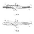
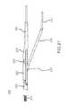
- FIG. 7illustrates a close-up partial cross-sectional view of a distal portion of the reentry catheter shown in FIG. 1 with a cannula in a retracted position;
- FIG. 8illustrates a close-up partial cross-sectional view of a distal portion the reentry catheter shown in FIG. 1 with a cannula in an advanced position;
- FIG. 9illustrates a close-up cross-sectional view of a distal portion of the reentry catheter according to FIG. 1 with a cannula in a retracted position;
- FIG. 10illustrates a close-up cross-sectional view of a distal portion of the reentry catheter shown in FIG. 9 with a cannula in an advanced position;
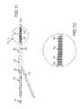
- FIG. 11illustrates a partially deconstructed side-view of the reentry catheter shown in FIG. 1 ;
- FIG. 12illustrates a close-up view of a distal portion of the reentry catheter shown in FIG. 11 ;
- FIG. 13illustrates a close-up view of a distal portion of the reentry catheter shown in FIG. 1 ;
- FIG. 14Aillustrates a close-up view of a distal portion of the reentry catheter shown in FIG. 1 ;
- FIG. 15Aillustrates an exemplary perspective view of a reentry catheter according to another embodiment of the invention.
- FIG. 15Billustrates an exemplary side-view of the reentry catheter shown in FIG. 15A ;
- FIG. 16Aillustrates an exemplary side view of a reentry catheter in a first configuration according to an embodiment of the invention
- FIG. 16Billustrates an exemplary side view of the reentry catheter in FIG. 16A in a second configuration
- FIG. 16Cillustrates an exemplary side view of the reentry catheter in FIG. 16A in a third configuration
- FIG. 16Dillustrates an exploded view of components of the reentry catheter in FIG. 16A ;
- FIG. 16Eillustrates a cross-sectional view of the reentry catheter in FIG. 16A along line C to C 1 ;
- FIG. 16Fillustrates a cross-sectional view of the reentry catheter in FIG. 16A along line D to D 1 ;
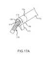
- FIG. 17Aillustrates a perspective view of the reentry catheter according to another embodiment of the invention.
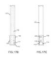
- FIG. 17Billustrates an exemplary side view of the reentry catheter illustrated in FIG. 17A ;
- FIG. 17Cillustrates an exemplary bottom view of a reentry catheter illustrated in FIG. 17A ;
- FIG. 17Dillustrates an end view of a cannula used in the reentry catheter illustrated in FIG. 17A ;
- FIG. 17Eillustrates an exemplary side view of the reentry catheter illustrated in FIG. 17A in a deployed position
- FIG. 17Fillustrates a side view of the reentry catheter according to another embodiment of the invention.
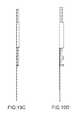
- FIG. 17Gillustrates a cutting head of the reentry catheter in FIG. 17F ;
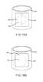
- FIG. 18Aillustrates a marker band in accordance with another embodiment of the invention.
- FIG. 18Billustrates a marker band in accordance with another embodiment of the invention.
- FIG. 19Aillustrates a perspective view of a marker band in accordance with another embodiment of the invention.
- FIG. 19Billustrates a top down view of a marker band in accordance with another embodiment of the invention.
- FIG. 19Cillustrates the marker band of FIG. 19A on a reentry catheter in a first orientation
- FIG. 19Dillustrates the marker band of FIG. 19B on a reentry catheter in a second orientation
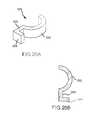
- FIG. 20Aillustrates a perspective view of a marker band in accordance with another embodiment of the invention.
- FIG. 20Billustrates a top down view of a marker band in accordance with another embodiment of the invention.
- FIG. 20Cillustrates the marker band of FIG. 20A on a reentry catheter in a first orientation
- FIG. 20Dillustrates the marker band of FIG. 20B on a reentry catheter in a second orientation
- FIG. 21Aillustrates a top view of a marker band in accordance with another embodiment of the invention.
- FIG. 21Billustrates the marker band of FIG. 21A on a reentry catheter in a first orientation
- FIG. 22Aillustrates a top view of a marker band in accordance with another embodiment of the invention.
- FIG. 22Billustrates the marker band of FIG. 22A on a reentry catheter in a first orientation
- FIG. 23Aillustrates a top view of a marker band in accordance with another embodiment of the invention.
- FIG. 23Billustrates the marker band of FIG. 22A on a reentry catheter in a first orientation
- FIG. 23Cillustrates the marker band of FIG. 22A on a reentry catheter in a second orientation
- FIG. 23Dillustrates the marker band of FIG. 22A on a reentry catheter in a third orientation
- FIG. 23Eillustrates a catheter with the marker band shown in FIG. 23A in various orientation from 60 left anterior oblique (LAO) to 60 right anterior oblique (RAO).
- LAOleft anterior oblique
- REOright anterior oblique
- FIG. 23Fillustrates a catheter with the marker band shown in FIG. 23A on a reentry catheter in various orientations from 60 left anterior oblique (LAO) to 60 right anterior oblique (RAO);
- FIG. 24Aillustrates a top view of a marker band in accordance with another embodiment of the invention.
- FIG. 24Billustrates the marker band of FIG. 24A on a reentry catheter in a first orientation
- FIG. 24Cillustrates the marker band of FIG. 24A on a reentry catheter in a second orientation
- FIG. 24Dillustrates the marker band of FIG. 24A on a reentry catheter in a third orientation.
- FIG. 24Eillustrates a catheter with the marker band shown in FIG. 23A in various orientations from 60 left anterior oblique (LAO) to 60 right anterior oblique (RAO).
- LAOleft anterior oblique
- REOright anterior oblique
- FIG. 24Fillustrates a catheter with the marker band shown in FIG. 23A on a reentry catheter in various orientations from 60 left anterior oblique (LAO) to 60 right anterior oblique (RAO);
- FIG. 25Aillustrates a top view of a marker band in accordance with another embodiment of the invention.
- FIG. 25Billustrates the marker band of FIG. 25A on a reentry catheter in a first orientation
- FIG. 25Cillustrates the marker band of FIG. 25A on a reentry catheter in a second orientation
- FIG. 25Dillustrates the marker band of FIG. 25A on a reentry catheter in a third orientation.
- FIG. 25Eillustrates a catheter with the marker band shown in FIG. 25A in various orientations from 60 left anterior oblique (LAO) to 60 right anterior oblique (RAO);
- FIG. 25Fillustrates catheter with the marker band shown in FIG. 25A on a reentry catheter in various orientation from 60 left anterior oblique (LAO) to 60 right anterior oblique (RAO).
- LAOleft anterior oblique
- REOright anterior oblique
- FIGS. 26A-26Fillustrates an exemplary method for using a medical device of FIG. 1 ;
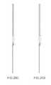
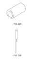
- FIG. 27illustrates a device manufactured as described in Example 1.
- FIG. 28illustrates a photograph of a reentry device manufactured as described in Example 2.
- the inventiongenerally relates to a method and system for crossing an obstruction, e.g., a chronic total occlusion in a blood vessel, and more particularly to a medical device method for crossing an occlusion in a subintimal or interstitial space of an artery.
- Subintimal or interstitial region or spaceis at a location beneath at least a portion of intima and preferably at a location contained between the intima and the adventitia of the vessel.
- tubular member, artery, vessel and bodily passableare used interchangeably throughout the specification.
- An embodiment of the inventionis directed towards a rapid exchange catheter for insertion into a subintimal space.
- the catheterincludes a proximal end, a distal end, lateral port, and a first lumen configured to receive a first wire.
- the first lumenextends longitudinally through at least the lateral port of the catheter.
- the catheteralso includes a second lumen having a portion extending distally of the lateral port and also extending through at least the distal end of the catheter.
- the first and second lumensare discontinuous with each other.
- the catheterfurther includes an exchange port, e.g., an RX port, arranged along an exterior portion of the catheter body and configured to receive a second wire.
- the RX portpermits the second wire to extend through the RX port and through the second lumen out the distal end of the catheter.
- the catheteris configured to advance with the second wire via the RX port. This is not an over the wire advancement as known to physicians skilled in the art, but rather utilizes the RX port which permits rapid transfer and aids in orientation of the catheter as described herein.
- the catheterincludes a proximal end, a distal end, at least one port, and at least one lumen.
- the at least one lumenextends longitudinally through a port of the catheter.
- the cathetermay also include an exchange port, e.g., RX port, arranged along an exterior portion of the catheter body and configured to receive a second wire or guide wire.
- the exchange portmay be broken into two or more segments along the length of the catheter.
- a reentry catheterfor use in forming a pathway in an interstitial space of an artery.
- the reentry catheterincludes a catheter body having a proximal end, a distal end, at least one lumen, and at least one lateral port.
- a rotating reentry cutteris arranged within the distal end portion of the catheter body and includes a leading edge and pivot attachment points coupled with the catheter body.
- at least a portion of the rotating reentry cutter leading edgeis configured with one or more sharp surfaces.
- the cutting surfacemay extend along the entire surface of the leading edge of the rotating reentry cutter.
- the cutting surfaceis configured to gain access from the subintimal or interstitial region or space to the true lumen of the vessel.
- the leading edge of the rotating reentry cutteris configured to deploy through the at least one lateral port from a first location within the interstitial space of an artery to a second location within a true lumen of the artery upon application of a substantially eccentric force to a portion of the rotating reentry cutter.
- At least one actuatorsuch a as tendon, tether, coil, cable, linkage of other suitable mechanism is coupled to a portion of the rotating reentry cutter configured to provide the application of a substantially eccentric force in relation to the pivot point.
- a control handlemay be incorporated near the proximal end of the reentry cutter for application of the eccentric force and/or for controlled displacement of the rotating cutter mechanism across the subintimal vessel layers.
- Still another embodiment of inventionis directed towards a catheter for insertion into a subintimal space.
- the catheterincludes a proximal end, a distal end, and at least one lumen for receiving a guide wire, and a distal portion of the catheter configured to split longitudinally to provide lateral and axial support. At least one port is exposed upon separation of the split catheter distal tip. At least one lumen extends longitudinally through the at least one port of the catheter.
- the catheterincludes a reentry member, e.g., a cannula, which is configured to gain access to a vessel true lumen from a subintimal space.
- the cannulais configured to penetrate the vessel layers adjacent to the at least one port.
- the cannulais configured to have a hollow portion to receive an interventional guide wire.
- the at least one lumenextends longitudinally through at least the port of the catheter.
- the reentry catheterincludes a catheter body having a proximal end, a distal end, at least one lumen, and at least one port.
- An exchange portis arranged on at least a distal portion of the catheter body.
- the exchange portincludes at least one lumen configured to receive a guidewire and the catheter body is configured to track over the guidewire to a treatment site.
- the reentry cannulaincludes a proximal end, a distal end, at least one lumen extending from the proximal end to the distal end.
- a tendonis coupled to a distal end portion of the reentry catheter. The tendon is configured to unlock the distal portion mechanism and the linear extension of the reentry cannula. The tendon can also be used to aid in the retraction of the split catheter distal portion from an extended to closed configuration.
- the reentry cannulaincludes a lumen for receiving a guide wire or supplemental treatment device.
- the supplemental treatment devicemay include guide wires, medical instruments, balloons, stents, laser catheters, optical fibers, visualization devices, medications and other medical instruments known in the art.
- the lumen portion of the reentry memberis configured to receive a guide wire having a diameter in a range from about 0.01 inches to about 0.04 inches or larger.
- a catheter systemin yet another embodiment, includes a catheter body having a proximal end, a distal end, a split distal portion, and at least one lumen wherein the lumen includes an opening.
- the split distal portionis configured to separate upon actuation of a pull or push mechanism to expose the at least one port, to provide a space for extension of the reentry cannula, and to allow the reentry cannula to reenter the true vessel lumen from the subintimal space.
- the split distal portionis configured to slide linearly while preventing radial expansion or separation.
- the reentry cannulais moveable, flexible and/or bendable from a first configuration to a second configuration, e.g., a retracted position to an operative position.
- the movementmay be achieved upon application of a force, e.g., an axial push force or pull force applied to a portion of the reentry cannula.
- the forcemay be generated with at least one of a push member; ramp; wedge; and electrically activated materials, including electroactive polymers, thermo-active polymers, electroactive metals and combinations thereof.
- these electrically activated materialsmay be activated with an electrical signal such as current or voltage as known in the art.
- the catheter body or the reentry membermay be constructed as described in U.S. Pat. No. 7,951,186, which is hereby incorporated by reference.
- the reentry cannulamay have a load or force built into the member.
- the reentry cannulamay have pre-resilient shape contained within the rigid distal portion of the catheter or other structure that prevents movement. After the split distal portion separates or other structure is removed, the reentry cannula is released from a first position to second position.
- any catheter hereinmay include an exchange port, e.g., RX port, arranged along an exterior portion of the catheter body and configured to receive a second wire or guide wire.
- the exchange portmay be broken into two or more segments along the length of the catheter.
- the first wire and second wireare guidewires, which may have diameters in a range from about 0.01 inches to about 0.04 inches or larger.
- the diameter of the first and second wiremay be different.
- the lateral portis oriented in range from about 0 degrees to about 180 degrees relative to the exchange port, preferably at about 25 degrees to about 90 degrees relative to the exchange port, and more preferably between about 40 degrees and about 75 degrees relative to the exchange port.
- the cathetermay be constructed from various materials as known in the art.
- the cathetermay be constructed from materials such as polyesters; polyurethanes; polyamides; polyolefins including polyethylene and polypropylene; and any copolymers thereof.
- suitable materialsinclude, but are not limited to: nylon; polyester elastomer; polyether/block polyamide, such as PEBAX, Hytrel, and/or Arnitel; polyamid such as Grilamid; flouro-polymer, such as Kynar; polyether ether ketone (PEEK); polyethylene (PE); polyurethane; polyolefin copolymer (POC); and tetrafluoroethylenes, such as polytetrafluoroethylene (PTFE).
- nylonpolyester elastomer
- polyether/block polyamidesuch as PEBAX, Hytrel, and/or Arnitel
- polyamidsuch as Grilamid
- flouro-polymersuch as Kynar
- PEEKpolyether
- the cathetermay comprise coils as described in U.S. Publication No. 2010/0063534, which is hereby incorporated by reference as if fully set forth herein.
- the cannulacan be constructed of various materials, e.g., steel, alloy, nitinol, combinations thereof and the like.
- the cannulais configured to permit other devices to be operated through the lumen of the cannula, e.g., a balloon, cutting device, guidewire, and the like.
- the cannulamay be configured to have a predetermined shape, i.e., resilient shape, straight shape, curved shaped, memory shape.
- the cannulamay also be sized to accommodate a wide range of guidewire diameters ranging from about 0.01 inches to about 0.04 inches or larger.
- Suitable materials for the split distal portioninclude rigid materials including but not limited to stainless steel, reinforced polymers, titanium, alloys, other metals or rigid materials coated with a biocompatible coating, and combinations thereof and the like.
- Another embodiment of the inventionis directed towards a method for crossing an obstruction in blood vessel.
- the methodincludes advancing a first wire into an interstitial space of a vessel.
- an undersized low profile balloon or other intervention dilation devicemay be used to pre-dilate the subintimal space prior to introduction of the rapid exchange catheter.
- a rapid exchange catheteris advanced into the subintimal space with the first wire. That is, the rapid exchange catheter is advanced along the first wire with the aid of the exchange port.
- a second wireis advanced down a central lumen of the rapid exchange catheter and the second wire is advanced through a lateral port of the rapid exchange catheter system into the lumen of the blood vessel.
- a cannulais configured to exit the lateral port into the true lumen of the vessel from the subintimal space prior to the second wire being advanced through the lateral port.
- a cannulaneed not be utilized.
- Another embodiment of the inventionis directed towards a method for crossing an obstruction in a blood vessel.
- the methodincludes advancing a first guide wire through a true lumen of vessel and into an interstitial space of the vessel.
- an undersized low profile balloon or other intervention dilation devicemay be used to pre-dilate the subintimal space prior to introduction of the reentry catheter.
- the reentry catheteris advanced into the subintimal space through either an over the wire or via a rapid exchange technique with the reentry member in a stowed position.
- the catheterthen advances through the subintimal space until the lateral port is distal to the total occlusion.
- the orientation and the location of the catheter and its lateral port with respect to the occlusionmay be directed through the use of radiopaque markers and visualization techniques known in the art.
- the operatormoves the reentry cannula or the split distal catheter portion from the stowed or locked position and subsequently separates the bottom and top layers of the split distal portion such that a cantilevered distal extension is in position to provide lateral and axial stability upon reentry.
- the reentry cannulais then advanced adjacent the at least one port and advanced for a precise penetration between the subintimal space and the true vessel lumen.
- a second interventional guide wirein the case of a rapid exchange catheter, or the first guide wire for an over the wire configuration is advanced into the vessel lumen through the hollow portion of the reentry member.
- the reentry membermay be retracted and the reentry cannula is refracted, the split catheter distal portion is retracted and locked, and the entire reentry catheter removed.
- more than one wiremay also be used in the over the wire technique.
- kitsincludes a catheter according to embodiments of the invention and directions for use.
- the kitmay also include a supplemental treatment device, e.g., a balloon, optical catheter, visualization catheter, stent, embolic protection device and the like.
- the kitmay include valves and other devices that may be used in medical procedures.
- FIG. 1illustrates a side view of a reentry catheter according to an embodiment of the invention.
- FIG. 2illustrates a perspective view of the reentry catheter shown in FIG. 1 .
- FIG. 3illustrates an internal view of the reentry catheter shown in FIG. 1 .
- a reentry catheteraccording to this embodiment is generally depicted as reference number 100 .
- the catheter 100is configured to permit a user to cross an obstruction, e.g., partial or total occlusion, in a subintimal space of a vessel.
- the catheter 100also enables fast and simple true lumen reentry without the need for visualization, e.g., IVUS visualization.
- the visualizationmay be active or passive as known in the art or described with reference towards U.S. Patent Application Publication No. 2005/0171478, which is hereby incorporated by reference.
- the catheter 100is flexible and has a proximal end 102 and a distal end 104 .
- the proximal end 102is attached to a handle (not shown).
- a shaft 106extends from the proximal end 102 of the catheter to the distal end of a rigid shroud 108 .
- a lateral port 110is located near the distal end and preferably in the rigid shroud 108 .
- a lateral portmay also be located in the shaft 106 and/or molded end portion 118 .
- the shaft 106includes a central lumen (not shown) extending at least partially along the entire shaft 106 .
- a flexible cannula 112may be contained in the inner lumen of the shaft 106 along substantially the length of the catheter 100 .
- the distal end of the shaft 106is connected to the proximal end of the shroud 108 , preferably by a laser weld, glue, over-molding or the like as known in the art.
- the cannula 112can be configured to permit other devices or supplemental devices to be operated through the lumen of the cannula 112 , e.g., balloon, cutting device, guidewire, filters, optical devices, e.g., RF or laser ablation devices, and the like.
- the cannula 112may be configured to have a predetermined shape, i.e., resilient shape, straight shape, curved shaped, memory shape.
- the cannula 112may also be sized to accommodate a wide range of guidewire diameters ranging from about 0.01 inches to about 0.04 inches or larger.
- a second guidewire 121having the foregoing dimensions is configured to exit a lumen of the cannula 112 in a preferred embodiment.
- an exchange port 114e.g., a rapid exchange port, is eccentrically located near the distal end of the shaft 106 .
- the port 114includes a jacketed polyimide tube trimmed flush to the profile of the device after processing to facilitate tracking and back loading of a guidewire 116 .
- the guidewire 116can have a diameter in a range from about 0.01 inches to about 0.04 inches or greater and be constructed of a range of materials as known in the art.
- the wire 116may have lubricous coating, e.g., PVP thin film or PTFE, and/or a predetermined shape.
- a molded end portion 118is coupled to the distal end of the shroud 108 .
- the molded end portion 118is configured to provide improved lateral support for launching the cannula 112 from a subintimal space to a vessel true lumen.
- the molded end portion 118provides an optional lateral extension, which is configured to provide stability during the initial orientation of the device over the central arc of the lesion.
- the molded end portion 118is configured to contain a wire guide 120 .
- the wire guide 120is configured to deliver a guidewire 116 from the exchange port 114 to the molded end portion 118 .
- the guidewire 116exits the distal end of the rapid exchange port 114 , enters the proximal end of the wire guide 120 and exits through a lumen near the distal end 104 of the molded end portion 118 .
- the wire lumensare interrupted to maintain compatibility with smaller profile crossover sheaths.
- the use of a discontinuous wire guideallows the outer diameter of the device to be smaller than would otherwise be required if a wire guide tube (not shown) were to travel parallel to the shaft center lumen along the rapid exchange port 114 , along the shroud 108 , and along the molded end portion 118 .
- Another embodiment of the inventionutilizes a non-discontinuous wire guide.
- the alignment of the exchange port 114 and the wire guide 120allow for back loading of the exchange wire 116 .
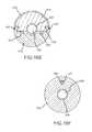
- FIG. 4illustrates an exemplary end view of the reentry catheter shown in FIG. 1 .
- FIG. 5illustrates an exemplary end view of a reentry catheter according to another embodiment of the invention.
- FIG. 6illustrates an exemplary end view of a reentry catheter according to another embodiment of the invention.
- an angle ⁇is defined between the axis of the rapid exchange port 114 and the central lumen axis of the lateral port 110 .
- FIG. 4shows a reentry catheter 100 where the angle ⁇ is at about a 90 degree orientation between the axis of the lateral port 110 and a central lumen axis of the rapid exchange port 114 .
- FIG. 5illustrates a reentry catheter 100 where angle ⁇ is at about a 65 degree orientation between the axis of the lateral port 110 and a central lumen axis of the exchange port 114 .
- FIG. 6shows a reentry catheter 100 where angle ⁇ includes about a 180 degree orientation between the axis of the lateral port 110 and a central lumen axis of the rapid exchange port 114 .
- the cannula 112would exit out the central lumen of the catheter and the rigid shroud 108 .
- the catheteris optimally sized for use in a 4 mm vessel where the natural tendency of the catheter will be to align along the outer surface of the vessel layer with the cannula in the launched position either oriented radially toward the central axis of the true vessel lumen or radially outward in a direction approximately 180 degrees away from the true vessel lumen central axis.
- the angle ⁇may be optimally sized for a particular vessel size, e.g. a 4 mm vessel, operation of the device is not restricted to a specific vessel size.
- angle ⁇may be in a range from about 0 degrees to about 360 degrees, preferably angle ⁇ is in a range from about 25 degrees to about 90 degrees, and more preferably angle ⁇ is in a range from about 40 degrees to about 75 degrees.
- FIG. 7illustrates a close-up partial cross-sectional view of a distal portion the reentry catheter shown in FIG. 1 with a cannula in a retracted position.
- FIG. 8illustrates a close-up partial cross-sectional view of a distal portion of the reentry catheter shown in FIG. 1 with a cannula in an advanced position.
- FIG. 9illustrates a close-up cross-sectional view of a distal portion of the reentry catheter according to FIG. 1 with a cannula in a retracted position.
- FIG. 10illustrates a close-up cross-sectional view of a distal portion of the reentry catheter shown in FIG. 9 with a cannula in an advanced position.
- the catheter 100includes an internal shaped tube 122 within the rigid shroud 108 near the lateral port 110 .
- the cannula 112is configured to exit through the lateral port 110 along an arc formed by the internal shaped tube 122 .
- the arc upon exit from the lateral portmay range from about 5 degrees to about 95 degrees measured from the central longitudinal axis of the catheter.
- the internal shaped tube 122includes an arc shaped end region upon exit from the lateral port ranges from about 5 degrees to about 85 degrees and preferably about 20 degrees to about 45 degrees.
- the internal shaped tube 122is contained within the rigid shroud 108 and is not integrated directly into the molded end portion 118 or shaft 106 .
- the internal shaped tubemay be integrated directly into the molded end portion 118 or shaft 106 and the lateral port may exit at that location.
- a deflection rampis utilized to guide the cannula 112 or wire 116 towards the inner lumen of a vessel.
- the catheter in this embodimentincludes a deflection ramp 124 near the lateral port 110 .
- the deflection ramp 124is positioned in the shroud 108 .
- the flexible cannula 112is configured to be deflected by the ramp 124 and exit the lateral port 110 .
- the angle of the ramp 124can range from about 5 degrees to about 85 degrees and preferably from about 20 degrees to about 45 degrees with respect to the central lumen axis of the shaft 106 . This preferred angle of exit for the cannula through the lateral port and into the true vessel lumen provides a clear advantage.
- a more orthogonal approachrelies on the hoop strength of the vessel to support reentry forces.
- the vessel wallmay tend to pull away from the cannula tip such that penetration will require an increased force application and possible multiple attempts to successfully enter the true vessel lumen.
- This feature coupled with the improved torsional strength of the shaft, as described below,results in more consistent reentry at a preferred location closer to the distal end of the occlusion.
- FIG. 11illustrates a partially deconstructed side-view of the reentry catheter shown in FIG. 1 .
- FIG. 12illustrates a close-up view of a distal portion of the reentry catheter shown in FIG. 11 .
- the catheter 100includes a shaft 106 that can be constructed of materials as discussed therein.
- the shaft 106includes a triplex coil construction also referred to as a drive cable or torque tube.
- This triplex coilincludes an outer jacket 150 and three coils each wound in opposite directions and then fixed at the ends by welding.
- the three coilsinclude a first coil 152 , a second coil 154 , and a third coil 156 .
- the distal end of the coil jacket 150is attached to the proximal end of the rigid shroud 108 by a laser weld or other attachment procedure as known in the art.
- the cannula 112is contained in an inner lumen defined by the coils.
- This coil designprovides enhanced flexibility for navigating tortuous vasculature while delivering superior torque transmission and torque control properties compared to a braided or double braided shaft.
- the coilscan be constructed of stainless steel flat wire, alloy wire, or other metal.
- the shaftmay also be constructed of other conventional materials, i.e., braided, double braided, and the like as known in the art.
- the windings of the coilsare orientated oppositely with respect to each adjacent coil.
- An optional molded end portion 118is configured to provide improved lateral support for launch of cannula 112 from a subintimal space to a vessel true lumen.
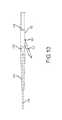
- FIG. 13illustrates a close-up view of a distal portion of the reentry catheter shown in FIG. 1 .
- FIG. 14Aillustrates a close-up view of a distal portion of the reentry catheter shown in FIG. 1 .
- the catheter 100optionally may include at least one orientation marker 128 or a plurality of orientation markers (not shown).
- the orientation markers 128are configured to ensure orientation of the lateral port towards the true lumen of the vessel.
- the orientation markers 128may also be configured to determine a spatial relationship of other attributes of the catheter, e.g., the spatial location of the distal end of the catheter 104 .
- the marker 128is arranged near a distal portion of the catheter 100 .
- the marker 128is configured as a radiopaque band around a distal portion of the rigid shroud 108 at a proximal portion of the molded tip 118 . The over molded tip 118 would then be secured over the marker band.
- the marker 128may be in the form of a marker band as described herein and epoxied, welded, soldered or press fit over the distal end of the rigid shroud 108 .
- the flexible molded tip 118then fits over the marker band 118 .
- cut outs or windows 1806 on the marker bandare configured such that different views on fluoroscopic images enable the operator to align the lateral port 110 so that the cannula 112 or other instrument, e.g., guidewire, working element, and the like, could be aligned such that deployment directs the cannula toward the true lumen of the vessel rather than in a direction away from the true lumen of the vessel.
- the catheter 100includes at least one orientation marker 128 or a plurality of orientation markers (not shown).
- the orientation markersare configured to ensure orientation of the lateral port towards the true lumen of the vessel.
- the orientation markersmay also be configured to determine a spatial relationship of other attributes of the catheter, e.g., the spatial location of the distal end of the catheter.
- the marker 128is arranged near a distal portion of the catheter.
- the marker 128is configured as a radiopaque band around a distal portion of the rigid shroud 108 at a proximal portion of the molded tip 118 . The over molded tip 118 would then be secured over the marker band.
- the marker band 128 in this embodimentincludes a second pattern cut out 132 in the form of two longitudinal slots 134 as described herein with reference to FIGS. 18A-25F .
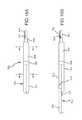
- FIG. 15Aillustrates an exemplary perspective view of a reentry catheter according to another embodiment of the invention.
- FIG. 15Billustrates an exemplary side-view of the reentry catheter shown in FIG. 15A .
- a reentry catheteraccording to this embodiment is generally depicted as reference number 200 .
- the catheter 200is configured to permit a user to cross an occlusion in a subintimal space of a vessel.
- the catheter 200is similar to the catheter described with reference to FIGS. 1-3 . That is, the catheter 200 enables fast and simple true lumen reentry without the need for active guided visualization, e.g., IVUS visualization, at a location near the physician's preferred location distal the total occlusion.
- the catheter 200is flexible and has a proximal end 202 and a distal end 204 .
- the proximal end 202is attached to a handle (not shown).
- a shaft 206extends from the proximal end 202 of the catheter to the distal end of a rigid shroud 208 .
- a lateral port 210is located near the distal end and preferably in the rigid shroud 208 .
- the shaft 206includes a central lumen (not shown) extending at least partially along the entire shaft 206 .
- a flexible cannula 212may be contained in the inner lumen of the shaft 206 along substantially the length of the catheter 200 .
- the distal end of the shaft 206is connected to the proximal end of the shroud 208 preferably by a laser weld, glue, or the like as known in the art.
- the cannula 212can be configured to permit other devices to be operated through the lumen of the cannula 212 , e.g., a balloon, cutting device, guidewire, and the like.
- the cannula 212may be configured to have a predetermined shape, i.e., resilient shape, straight shape, curved shaped, memory shape.
- the cannula 212may also be sized to accommodate a guidewire 215 .
- the guidewire 215may have a diameter in a range from about 0.01 inches to about 0.04 inches or larger.
- the cannula 212can have a lumen sized to support the delivery of vascular treatments through the subintimal space into the vessel true lumen without the assistance of a separate cannula or treatment guidewire.
- a port 214e.g., a rapid exchange port is eccentrically located near the distal end of the shaft 206 .
- the port 214includes a jacketed polyimide tube trimmed flush to the profile of the device after processing to facilitate tracking and back loading of a wire 216 , e.g., an exchange wire.
- the wire 216e.g., an exchange wire, can range in diameter from about 0.01 inches to about 0.04 inches or larger and be constructed of a range of materials as known in the art.
- the wire 216may have lubricous coating, e.g., PVP thin film or PTFE, and/or a predetermined shape. In this embodiment, there is no molded end portion as shown in FIGS. 1-3 .
- FIG. 16Aillustrates an exemplary side view of a reentry catheter in a first configuration according to an embodiment of the invention.
- FIG. 16Billustrates an exemplary side view of the reentry catheter in FIG. 16A in a second configuration.
- FIG. 16Cillustrates an exemplary side view of the reentry catheter in FIG. 16A in a third configuration.
- a reentry catheteraccording to this embodiment is generally depicted as reference number 1600 .
- the catheteris configured to permit a user to cross an obstruction, e.g., a partial or total occlusion, in a subintimal space of a vessel.
- the catheteralso enables fast and simple true lumen reentry without the need for active visualization, e.g., IVUS visualization.
- Visualizationmay be used to assist procedures of the invention, e.g., the visualization may be active or passive.
- visualization featuresare added as described with reference towards U.S. Patent Application Publication No. 2005/0171478, which is hereby incorporated by reference.
- the catheter 1600includes a split tip distal portion 1602 coupled to a shaft coupler 1604 and a catheter shaft 1606 including at least one lumen 1608 .
- the lumen 1608 of the catheter shaft 1606is configured to receive a reentry cannula 1610 slidably disposed within the at least one lumen 1608 .
- the cannula 1610can be configured to permit other devices to be operated through the lumen of the cannula 1610 , e.g., a balloon, cutting device, guidewire, and the like.
- the cannula 1610may be configured to have a predetermined shape, i.e., resilient shape, straight shape, curved shaped, memory shape.
- the cannula 1610may also be sized to accommodate a wide range of guidewire diameters such as guidewire diameters in a range from about 0.01 inches to about 0.04 inches or larger.
- the cannula 1610can have a lumen sized to support the delivery of vascular treatments through the subintimal space into the vessel is true lumen without the assistance of a separate cannula or treatment guidewire.
- the reentry cannula 1610may be configured to permit other devices or supplemental devices to be operated through the lumen of the cannula.
- the supplemental devicesmay include a balloon, a cutting device, a thrombectomy device, a guidewire, filters, e.g., an embolic filter, optical devices, RF or laser ablation devices or combinations and the like.
- the reentry cannulamay be configured to have a predetermined shape, e.g., pre-resilient shape, straight shape, curved shaped, memory shape and combinations of the same.
- the catheteris flexible and has a proximal end and a distal end.
- the proximal endis attached to a handle (not shown).
- the shaft 1606extends from the proximal end of the catheter to the distal end of a shaft coupler 1604 or the split distal portion 1602 .
- the shaft 1606may be constructed of conventional techniques.
- the shaft 1606includes braided, double braided, or triplex construction as described with reference to FIGS. 11 and 12 herein.
- the first orientation in FIG. 16Ais a closed configuration or the split tip 1602 portion in a home position.
- the catheter 1600is in a second and third configuration.
- the second configurationis positioned having the split tip 1602 in an open configuration, e.g., one portion of the split tip extends past another portion of the split tip to expose a port or opening 1612 .
- the extensioncan either occur as a result of the cannula 1610 pushing an upper split tip portion 1614 past a bottom split tip portion 1619 or by translation of a push force directly on the split tip top portion.
- a distal portmay also be located in the shaft.
- the shaft 1606includes at least one lumen extending at least partially along the entire shaft and exiting out of the catheter distal end.
- the cannula 1610extends out of a port or opening 1612 of the catheter 1600 , e.g., deflects off a ramp on an internal portion of the catheter.
- a wire 1616e.g., Kevlar tendon having a high tensile strength and low bend stiffness is configured to retract the upper split 1614 tip from an extended position to a home position.
- the tendon 1616is coupled to an upper split 1614 tip at a location 1618 .
- FIG. 16Dillustrates an exploded view of the components of the reentry catheter in FIG. 16A .
- the various catheter componentsare illustrated and include a distal end of shaft 1606 connected to the proximal end of a rigid shaft coupler 1604 .
- the shaft 1606is connected to the shaft coupler 1604 by laser welding, glue, over-molding or other techniques as known in the art.
- the distal end of the coupler 1604is coupled with the rigid shroud cover 1615 and the split tip bottom portion 1619 .
- the shroud cover 1615may include stainless steel or other suitable material.
- the split tip top portion 1614is slidably coupled with the split tip bottom portion 1619 .
- a lumen 1608is disposed in the catheter shaft 1606 , and can be fabricated of PTFE or other suitable thermoplastic material as known in the art.
- the lumenmay optionally include a liner 1620 made of thermoplastic material, e.g., a PTFE liner.
- a reentry cannula 1610made of nitinol or other suitable material as described herein, is disposed within at least one lumen 1608 and extends from the proximal end to the distal portion of the catheter.
- a tendon 1616made of Kevlar or other suitable material with a high tensile strength and a low bend stiffness, is coupled to a distal portion of the reentry cannula and fastened to a proximal portion of the split tip top.
- the tendon 1616may also be arranged in a lumen 1617 , e.g., PTFE braided lumen.
- a flexible atraumatic tipmay be attached to the distal end of the split tip top by laser weld, glue, over-molding or the like.
- FIG. 16Eillustrates a cross-sectional view of the reentry catheter in FIG. 16A along line C to C 1 .
- FIG. 16Fillustrates a cross-sectional view of the reentry catheter in FIG. 16A along line D to D 1 .
- the split tip top portion 1614 and split tip bottom portion 1619are keyed in a dove tail configuration 1624 to provide a slidably locking interface.
- Hard stops 1626are incorporated in the split tip to prevent over extension of the split top portion 1614 .
- the shroud cover 1615is welded at least at weld joints 1627 to the split tip bottom 1619 thereby prohibiting the cannula from exiting through a port 180 degrees opposite the desired reentry direction. While a dovetail configuration is shown, other keyed or locking interfaces can be utilized. Additionally, linear slides or bearing surfaces can also be incorporated. Referring now to FIG.
- a cross-section view of the catheter shaft at a location proximal to the shaft coupleris depicted.
- a lumen 1617is constructed of a low friction material, such as PTFE, within the catheter shaft.
- This lumen 1617contains the tendon 1616 which is used to control the retraction of the split upper tip 1614 from an extended to a stored or home position.
- the distal tip portionis docked in a non-extended and locked position and the reentry catheter is docked in a straight position, as shown in FIG. 16A while traversing through an artery and into or reversed out of the subintimal vessel space.
- At least one marker as described hereinis disposed on the body of the catheter near its distal end or integrated within the body of the catheter.
- the radiopaque markeris used with standard visualization techniques, e.g. fluoroscopy, to guide the catheter through the body and into position in the subintimal space, to position the port 1612 and rotating reentry cannula 1610 at a desired location distal to the occlusion, and to determine whether the rotating reentry cutter is in the stowed, ready, or in a fully deployed position.
- an operatorcould mechanically control and position the device as similarly described with reference to FIGS. 26A-26F .
- a usercould open the split tip 1602 when the catheter after the catheter is in the desired position at a location distal to the occlusion.
- an operatorcould mechanically control the reentry cannula by holding the catheter and advancing the cannula such that the distal end pushes or extends the split tip top 1614 to provide a cantilevered support and opening 1612 .
- the operatorcould extend the split tip top 1614 by exertion of a push or other appropriate force applied to the proximal end of the split tip top 1614 with a mechanical rod or other means.
- a handlemay be configured to transmit force from the proximal end of the catheter to a proximal portion of the reentry cannula 1610 and/or the split tip top 1614 .
- the hard stops 1627 in the split tip bottom 1619prevent the overextension of the split tip top 1614 and the locking interface between the split tip top and the split tip bottom prevents relative radial motion.
- the split tip top 1614extends from a direct pushing force of the distal end of the reentry cannula against the distal tip of the split tip top 1614 .
- This movement of the reentry cannulais from an orientation of about parallel to the vessel wall to an orientation between about 0 and about 180 degrees of the vessel wall and more preferably between about 5 and about 90 degrees with respect to the vessel wall and allowing the leading edge of the cannula to penetrate the vessel wall.
- the operatorwould open the split tip 1602 with a push or other appropriate force applied to its proximal end.
- the cannulawould then be moved from stowed to ready and then launch position as shown in FIG. 26D .
- This movement of the reentry cannulais from an orientation of about parallel to the vessel wall to an orientation between about 0 and about 180 degrees of the vessel wall and more preferably between about 5 and about 90 degrees with respect to the vessel wall and allowing the leading edge of the cannula to penetrate the vessel wall.
- the split tip top in its fully extended positionprovides necessary lateral and axial support to prevent the device from backing out in response to the reentry forces encountered, particularly in the presence of calcified tissue.
- mechanical advantage componentssuch as levers, manual gearing or electro-mechanical gearing may be incorporated near the proximal end of the catheter and more preferably in the handle such that the reentry cannula may be mechanically controlled through a simple one-handed operation.
- the activation mechanismmay be linked to a simple handle such that the operator either rotates a knob or activates a mechanical or electro-mechanical control element to transition from a ready to an articulated or flexed configuration.
- the intervention guidewire or another appropriate devicemay be passed through the shaft lumen and the lumen of the reentry cannula into the true vessel lumen.
- the vessel walltends to pull away from a more traditional reentry cannula tip such that penetration will require an increased force application and possible multiple attempts to successfully enter the lumen.
- the use of a split tip top in its fully extended positionprovides necessary lateral and axial support to prevent the device from backing out in response to the reentry forces encountered, particularly in the presence of calcified tissue.
- the use of the split distal tipovercomes this challenge posed by the prior art and allows the operator to reenter at their preferred location easily and repeatedly.
- the use of the split tip catheterresults in more consistent reentry at a location closer to the distal point of the occlusion as compared to the use of a simple catheter with an extended flexible tip as known in the art.
- the profile of the cathetercan be much smaller than reentry devices known in the art since the distal split extending portion can be of sufficient length to support the moment created from the reactionary forces on the catheter during reentry.
- Known reentry devicesincorporate a flexible distal extension that is limited in length due to the larger tip profile. This restriction is necessary to ensure tracking and control through tortuous anatomy.
- This inventionovercomes the problems with the prior art by allowing for a longer and more rigid distal support structure upon reentry while maintaining a substantially reduced profile while traversing through tortuous anatomy.
- the reentry cannulaAfter the proper reentry of the reentry cannula has been confirmed to be directed towards the true lumen of the vessel, another instrument, e.g., a guidewire, working element, and the like, exits the cannula's distal port and reenters the vessel.
- another instrumente.g., a guidewire, working element, and the like, exits the cannula's distal port and reenters the vessel.
- the intervention guidewire or intervention deviceOnce the intervention guidewire or intervention device is in position, the reentry cannula is retracted back into the cannula exit port of the catheter, the tendon is activated with a pull force to return the extended split tip top to its un-retracted position, and the catheter is removed leaving the interventional device or guidewire in position.
- both the catheter and guidewiremay be left in place. Now that the total occlusion is crossed various interventional procedures as known in the art may be performed.
- a balloon cathetermay be used to dilate the subintimal space along with possible stent placement (not shown) to provide an alternative lumen through the subintimal space and back into the true vessel to restore adequate blood flow post-procedure.
- FIG. 17Aillustrates a perspective view of the reentry catheter according to another embodiment of the invention.
- FIG. 17Billustrates an exemplary side view of the reentry catheter illustrated in FIG. 17A .
- FIG. 17Cillustrates an exemplary bottom view of a reentry catheter illustrated in FIG. 17A .
- FIG. 17Dillustrates an end view of a cannula used in the reentry catheter illustrated in FIG. 17A .
- FIG. 17Eillustrates an exemplary side view of the reentry catheter illustrated in FIG. 17A in a deployed position.
- a reentry catheteris generally depicted as reference number 1700 .
- the reentry catheter 1700includes a catheter body or flexible shaft 1702 connected to a rigid shroud 1704 .
- the shaft 1702includes at least one lumen 1706 , at least one lateral port 1708 and at least one distal port 1710 .
- the cathetercan be alternatively configured with an exchange port (not shown), e.g., an exchange port shown in FIGS. 15A-15B .
- a rotating reentry cutter 1712is disposed within the rigid shroud 1704 and coupled to the shroud at pivot points 1714 .
- the rotating reentry cutter 1712is configured to rotate about the pivot axis 1714 from a stowed position within the rigid shroud 1704 to a fully deployed position.
- the shaftmay be constructed of conventional techniques or constructed as described herein.
- the shaftincludes braided, double braided, or by triplex construction as described herein with reference to FIGS. 11-12 .
- the distal end of the shaftis connected to the proximal end of the shroud preferably by a laser weld, glue, over-molding or the like as known in the art.
- a flexible atraumatic tipmay be attached to the distal end of the shroud 1704 preferably by a laser weld, glue, over-molding or the like as known in the art.
- the shroud 1704 or covermay extend to the catheter distal end and be formed with an atraumatic tip profile.
- an over molded distal extension (not shown) of the cathetermay be incorporated to provide additional support during device orientation and during launch of the rotating reentry cutter.
- the rotating reentry cutter 1712is docked within a channel of the rigid shroud, as shown in FIGS. 17B and 17C while traversing through an artery and into or reversed out of the subintimal vessel space.
- a retractable shroud or covermay be used to protect the vessel during catheter transport through the body.
- the lumen 1706may be configured to receive a secondary treatment device 1716 , e.g., a flexible crossing support catheter.
- a secondary treatment device 1716e.g., a flexible crossing support catheter.
- the lumen 1706 of the reentry catheter 1700is sized to accommodate a wide range of guidewire diameters such as guidewire diameters in a range from about 0.01 inches to about 0.04 inches or larger.
- the guidewirepasses through a lumen of the reentry catheter and passes through the distal end of the catheter as would be the case when the catheter travels through the body and into or out of the subintimal space.
- a support catheter 1716is shown passing through a lumen of the reentry catheter and passing through the distal end of the catheter as would be the case when the support catheter is used to enter the vessel true lumen.
- the lumen of the catheteris designed to allow insertion or integration of a support catheter 1716 at least partially within the catheter inner lumen 1710 .
- the catheter inner lumen 1706can also be sized to support a flexible support or crossing catheter, such as a QuickCross® Extreme catheter (The Spectranetics Corporation, Colorado Springs, Colo.).
- a support catheter with a distal end, a proximal end, a distal port, and at least one lumenis coupled with the reentry catheter and contained within the at least one catheter lumen.
- the support catheteris not directly integrated with the reentry catheter.
- the support catheteris integrated within the reentry catheter.
- the support catheteris configured within at least a portion of the distal end of the reentry catheter.
- the support cathetercan extend substantially from the proximal to the distal end of the reentry catheter.
- the support catheteris configured to slidably move within the at least one lumen of the reentry catheter such that the support catheter can extend beyond at least one port of the reentry catheter.
- the support catheteris further configured for use with a conventional guidewire or supplemental treatment device within at least one lumen.
- the rotating reentry cutter 1712is configured to receive a guidewire 1717 or other supplemental instrument as described herein.
- an operatorcan control or operate the rotating reentry cutter 1712 by holding the catheter in place and by actuating at least one push or pull control element 1718 at a proximal location.
- an eccentric forceis applied to the rotating reentry cutter 1712 at a distance away from the pivot point 1714 by at least one push or pull member 1718 , such that a leading edge 1713 of the rotating of the cutter 1712 moves from a first position contained within the rigid shroud into a second position such that the leading edge is either adjacent to or penetrating vessel layers.
- the pull element or actuator 1718can be a tether, tendon, coil, linkage or other suitable mechanism and is coupled to a portion of the rotating reentry cutter 1712 to apply an eccentric force to the rotating reentry cutter.
- Preferably two tendons or control elementsare attached to the cutter. These control elements can be linked to a handle and actuated through simple one-handed operation such as slides, knobs, and the like as known in the art. Application of an opposite eccentric load causes the rotary reentry cutter to return from the extended or deployed position to a fully retracted position within the rigid distal portion.
- a control element 1718is used to transmit force from the proximal end of the catheter to a portion of the rotating reentry cutter 1712 at distance from the pivot point 1714 .
- the location of the control element 1718 and the placement of the coupled endare such that a moment is created causing the rotating reentry cutter 1712 to rotate about its pivot joint 1714 from a stowed to a deployed position.
- the reentry catheter 1700is configured to permit a user to cross an obstruction, e.g., a partial or total occlusion, in a subintimal space of a vessel.
- the catheter 1700also enables fast and simple true lumen reentry without the need for active visualization, e.g., IVUS visualization.
- Visualizationmay be used to assist procedures of the invention, e.g., the visualization may be active or passive.
- visualization features or systemsare added as described with reference towards U.S. Patent Application Publication No. 2005/0171478, which is hereby incorporated by reference.
- At least one markere.g., a radiopaque marker
- a radiopaque markeris disposed on the body of the catheter near its distal end or integrated within the body of the catheter.
- the radiopaque markeris used with standard visualization techniques, e.g. fluoroscopy, to guide the catheter through the body and into position in the subintimal space, to position the lateral port and rotating reentry cutter at a desired location distal to the occlusion, and to determine whether the rotating reentry cutter is in the stowed, ready, or in a fully deployed position.
- the reentry catheter 1700includes a reentry cutter 1712 in a stowed position within the rigid shroud 1704 at a location more proximal than shown in FIG. 17A .
- This more proximal positionallows for the leading edge of the cutter 1712 to be stowed near the distal end of the catheter and provides more clearance for supplemental devices, e.g., clearance for the crossing guidewire or a support catheter, such as the QuickCross® Extreme (The Spectranetics Corporation, Colorado Springs, Colo.), through a lateral port.
- the advantage of this configurationis that the crossing reentry guidewire is positioned adjacent to the location of the laceration in the subintimal layers created by the rotating reentry cutter.
- an internal ramp(not shown), or the like, can be integrated in the distal end of the catheter shaft and the proximal end of the rigid shroud to guide the reentry guidewire or support catheter through a lateral port.
- the reentry guidewirecan also be fed through an exchange port and enter the body of the catheter at a point proximate to the lateral port.
- Such a configurationmay provide the advantage of lower friction forces and improved ease-of-use when the reentry catheter is removed from the vessel upon successful crossing of the occlusion.
- the reentry cathetercan be either a traditional over the wire configuration or a rapid exchange configuration.
- a single guidewirecan be utilized through the lumen of the catheter.
- one guidewirecan pass through at least one lumen and at least one distal port or at least one exchange port while a second guidewire is used to reenter the true lumen of the vessel from a position distal to the occlusion.
- FIG. 17Fillustrates a side view of the reentry catheter according to another embodiment of the invention.
- FIG. 17Gillustrates a cutting head of the reentry catheter in FIG. 17F .
- the reentry catheter 1700includes a rotating reentry cutter 1712 rotabably coupled with a pivot 1714 attachment unit.
- the cutter 1712has a curvature 1721 on its surface adjacent to the reentry guidewire's lateral exit port that is used to deflect the reentry guidewire in a direction toward the true lumen of the vessel.
- the curvature 1721 of the cutting bladecan be used as a deflecting guide to direct the reentry crossing guidewire 1725 from a first position within a subintimal space, through the lateral port 1708 , along the curvature of the guidewire, through the laceration zone created by the rotating reentry cutter 1712 and into a second position within the vessel true lumen.
- An internal ramp (not shown) within the distal portion of the cathetercan also serve to direct the crossing guidewire through the laceration.
- a guidewire 1723may be slidably arranged on a curvature 1721 of the rotating cutter 1712 .
- the wire 1723may be a crossing guidewire and be retained in a channel, retaining rings, or the like, along an edge of the rotating reentry cutter 1712 to serve as a guide to direct the wire 1723 through the laceration created by the rotating reentry cutter when deployed.
- the reentry guidewire 1723could be loaded and locked onto the rotating reentry cutter prior to the entry of the catheter into the body.
- At least one marker as described hereinis disposed on the body of the catheter near its distal end or integrated within the body of the catheter.
- the radiopaque markeris used with standard visualization techniques, e.g. fluoroscopy, to guide the catheter through the body and into position in the subintimal space, to position the port and rotating reentry cannula at a desired location distal to the occlusion, and to determine whether the rotating reentry cutter is in a stowed, ready, or fully deployed position.
- FIGS. 26A-26Fthe crossing of an obstruction in a blood vessel with a reentry catheter in a subintimal space of a vessel is described.
- an eccentric loadcould be applied, as described herein, to rotate the cutter once the reentry catheter is in position within the subintimal space at a location distal to a total occlusion ( FIG. 26C ).
- the crossing guidewire 1723is released from its locked position and then guided through the laceration into the true lumen of the vessel.
- the guidewire 1723may include lubricious coating and have a diameter in a range from about 0.01 inches to about 0.04 inches or larger.
- the guidewiremay be shapeable, deformable, or have other attributes designed for crossing an occlusion directly or indirectly.
- the actuation of the deployment forcemay be performed through a handle control actuation mechanism near the proximal end of the device as known in the art.
- an axial pull or push forceis applied to the reentry catheter causing the sharp edge of the rotating reentry cutter 1712 to lacerate the subintimal layers of the vessel ( FIG. 26D ).
- the length of the lacerationcan be limited by controls, known in the art, such that the catheter moves a controlled or fixed distance.
- a wire, internal support catheter, or interventional deviceis then deployed through a distal port from within the subintimal space of the vessel to a second location within a true lumen of the vessel.
- An internal wedge or ramp near the distal end of the reentry cathetercan deflect the crossing device towards the true lumen of the vessel.
- the crossing deviceexits a lateral port and is directed towards the true vessel lumen by a variety of means as described herein including the use of a ramp or wedge, guidance along the inner curvature of the rotating cutter device, or retention of the guidewire within a channel or retaining mechanism such that it is directed towards the laceration formed by the rotating reentry cutter and towards the vessel true lumen.
- the methodmay include returning the rotating reentry cutter from the second location to the first location and removing the reentry catheter and support catheter ( FIG. 17C , closed position), if using, from the vessel ( FIG. 26F ).
- FIG. 18Aillustrates a marker band in accordance with another embodiment of the invention.
- FIG. 18Billustrates a marker band in accordance with another embodiment of the invention.
- FIGS. 18A and 18Bgenerally depict a marker or marker band 1802 .
- the marker band 1802includes is formed as a band and includes a first window cut out 1806 and a second window cut out 1804 . This embodiment is directed towards a negative window approach.
- the first or second cut out windowmay be configured into any number of geometric configurations, e.g., discrete directional shapes, such as but not limited to letters, e.g., “D”, “P”, “E”, “F”; having a mirror image that differs from the original image; unique shapes such as arrows, multiple rectangular slots; or other directional configurations and combinations thereof.
- the marker band 1802is formed from material that is visible under fluoroscopy, e.g., radiopaque materials. More specifically, FIG. 18A illustrates an embodiment with a second pattern cut out 1802 in the form of an arrow 1808 .
- FIG. 18Billustrates an embodiment with a second pattern cut out 1804 in the form of a “D” shape 1810
- FIG. 19Aillustrates a perspective view of a marker band in accordance with another embodiment of the invention.
- FIG. 19Billustrates a top down view of a marker band in accordance with another embodiment of the invention.
- FIG. 19Cillustrates a marker band of FIG. 19A on a reentry catheter in a first orientation.
- FIG. 19Dillustrates a marker band of FIG. 19B on a reentry catheter in a second orientation.
- a marker bandis generally depicted as reference number 1900 .
- the marker band 1900uses a positive approach rather the negative window band approach show in FIGS. 18A-18B .
- the marker band or marker 1900is formed from material that is visible under fluoroscopy, e.g., radiopaque materials.
- the marker band 1900is formed with platinum iridium materials.
- the marker band 1900is configured to be attached to a distal portion of any catheter described herein.
- the marker band 1900includes a first ring 1902 , a second ring 1904 , and an oversized central portion 1906 extending only partially in a circular manner.
- a first longitudinal strip 1908connects the first ring 1902 to a central portion 1906 and a second longitudinal strip 1910 connects the second ring 1904 to a central portion 1906 .
- FIG. 19Cillustrates a marker band of FIG. 19A on a reentry catheter in a first orientation.
- FIG. 19Dillustrates a marker band of FIG. 19B on a reentry catheter in a second orientation.
- the marker band 1900is attached to a distal portion of the reentry catheter with a laser tack welding process in a configuration to indicate a specific orientation of a lateral port of the reentry catheter.
- the marker bandis attached to at the distal end of a rigid shroud of the laser catheter, however, other orientations and locations on the reentry catheter are possible.
- the orientation of the lateral port with respect to a vessel wall or other desired trajectorycan be determined under a fluoroscopy visualization technique.
- FIG. 19Cshows an anteroposterior (AP) view and in this configuration the maker orientation under fluoroscopy shows a lateral port aligned on top of a vessel such that the cannula (not shown) can be extended into a vessel.
- FIG. 19Dshows that the cannula will extend into a vessel true lumen.
- FIG. 20Aillustrates a perspective view of a marker band in accordance with another embodiment of the invention.
- FIG. 20Billustrates a top down view of a marker band in accordance with another embodiment of the invention.
- FIG. 20Cillustrates a marker band of FIG. 20A on a reentry catheter in a first orientation.
- FIG. 20Dillustrates a marker band of FIG. 20B on a reentry catheter in a second orientation.
- a marker or marker bandis generally depicted as reference number 2000 .
- the marker band 2000uses a positive approach rather than the negative window band approach show in FIGS. 18A-18B .
- the marker band 2000is formed from material that is visible under fluoroscopy, e.g., radiopaque materials.
- the marker band 2000is formed with platinum iridium materials.
- the marker band 2000is configured to be attached to a distal portion of any catheter described herein.
- the marker 2000includes half circle region 2002 , a straight region 2004 , and another straight region 2006 at an orthogonal orientation to the straight region 2004 .
- the marker band 2000is attached to a distal portion of the reentry catheter with a laser welding process in a configuration to indicate a specific orientation of a lateral port of the reentry catheter.
- the half circle region 2002is used as an indicator of the cannula launch direction under fluoroscopy visualization.
- FIG. 20Cshows an anteroposterior (AP) view and in this configuration the marker orientation under fluoroscopy shows a lateral port aligned on top of a vessel such that the cannula (not shown) can be extended into a vessel.
- FIG. 20Dshows an orientation such that the cannula will extend into a vessel true lumen, e.g., at 30 RAO.
- FIG. 21Aillustrates a top view of a marker band in accordance with another embodiment of the invention.
- FIG. 21Billustrates a marker band of FIG. 21A on a reentry catheter in a first orientation.
- a marker band or markeris generally depicted as reference number 2100 .
- the marker band 2100uses a positive approach rather than the negative window band approach show in FIGS. 18A-18B .
- the marker band 2100is formed from material that is visible under fluoroscopy, e.g., radiopaque materials. In this embodiment, the marker band 2100 is formed with platinum iridium materials.
- the marker band 2100is configured to be attached to a distal portion of any catheter described herein.
- the marker band or marker 2100includes a tip portion 2102 and a cut portion 2104 . More specifically, the cut portion 2104 is at an angle from about 15 degrees to about 75 degrees into the paper.
- the band 2100is attached to a distal portion of the reentry catheter with a laser welding process in a configuration to indicate a specific orientation of a lateral port of the reentry catheter.
- a fluoroscopy visualization techniquethe orientation of the lateral port with respect to a vessel wall or other desired trajectory can be determined.
- FIG. 21Bshows an anteroposterior (AP) view and in this configuration the maker orientation under fluoroscopy shows a lateral port aligned on top of a vessel such that the cannula (not shown) can be extended into a vessel.
- APanteroposterior
- FIG. 22Aillustrates a top view of a marker band in accordance with another embodiment of the invention.
- FIG. 22Billustrates a marker band of FIG. 22A on a reentry catheter in a first orientation.
- a marker band or markeris generally depicted as reference number 2200 .
- the marker band 2200uses a positive approach rather than the negative window band approach show in FIGS. 18A-18B .
- the marker band 2200is formed from material that is visible under fluoroscopy, e.g., radiopaque materials.
- the marker band 2200is formed with platinum iridium materials.
- the marker band 2200is configured to be attached to a distal portion of any catheter described herein.
- the marker band 2200includes an oval geometry.
- the band 2200is attached to a distal portion of the reentry catheter with a laser welding process in a configuration to indicate a specific orientation of a lateral port of the reentry catheter.
- a fluoroscopy visualization techniquethe orientation of the lateral port with respect to a vessel wall or other desired trajectory can be determined.
- FIG. 22Bshows an anteroposterior (AP) view and in this configuration the marker orientation under fluoroscopy shows a lateral port aligned on top of a vessel such that the cannula (not shown) can be extended into a vessel.
- APanteroposterior
- FIG. 23Aillustrates a top view of marker band in accordance with another embodiment of the invention.
- FIG. 23Billustrates the marker band of FIG. 22A on a reentry catheter in a first orientation.
- FIG. 23Cillustrates the marker band of FIG. 22A on a reentry catheter in a second orientation.
- FIG. 23Dillustrates the marker band of FIG. 22A on a reentry catheter in a third orientation.
- the marker band or markeris generally depicted as reference number 2300 .
- the marker band 2300uses a positive approach rather than the negative window band approach shown in FIGS. 18A-18B .
- the marker band 2300is formed from material that is visible under fluoroscopy, e.g., radiopaque materials.
- the marker band 2300is formed with platinum iridium materials.
- the marker band 2300is configured to be attached to a distal portion of any catheter described herein.
- the marker band 2300includes two vertical slots 2302 and 2304 , respectively.
- the band 2300is attached to a distal portion of the reentry catheter with a laser welding process in a configuration to indicate a specific orientation of a lateral port of the reentry catheter.
- the guidewire 2306 of the deviceis on the left and in this orientation the cannula (or lateral port) would be pointing into the page as indicated by the arrow.
- the guidewire 2304 of the deviceis on the right and in this orientation the cannula (or lateral port) would be pointing out of the page as indicated by the arrow.
- FIG. 23Dthe guidewire 2304 of the device is on the right and in this orientation the cannula (or lateral port) is not aligned.
- FIG. 23Eillustrates a catheter with a marker band shown in FIG. 23A in various orientations from 60 left anterior oblique (LAO) to 60 right anterior oblique (RAO).
- LAOleft anterior oblique
- RAOright anterior oblique
- FIG. 23Fillustrates a catheter with a marker band shown in FIG. 23A on a reentry catheter in various orientations from 60 left anterior oblique (LAO) to 60 right anterior oblique (RAO).
- LAOleft anterior oblique
- RAOright anterior oblique
- FIG. 24Aillustrates a top view of a marker band in accordance with another embodiment of the invention.
- FIG. 24Billustrates the marker band of FIG. 24A on a reentry catheter in a first orientation.
- FIG. 24Cillustrates the marker band of FIG. 24A on a reentry catheter in a second orientation.
- FIG. 24Dillustrates the marker band of FIG. 24A on a reentry catheter in a third orientation.
- the marker band or markeris generally depicted as reference number 2400 .
- the marker band 2400uses a negative approach.
- the marker band 2400is formed from material that is visible under fluoroscopy, e.g., radiopaque materials.
- the marker band 2400is formed with platinum iridium materials.
- the marker band 2400is configured to be attached to a distal portion of any catheter described herein.
- the marker band 2400includes two “D” type shape 2402 .
- the band 2400is attached to a distal portion of the reentry catheter with a laser welding process in a configuration to indicate a specific orientation of a lateral port of the reentry catheter.
- a clear “D” type shapeis shown and the guidewire 2404 of the device is on the left and in this orientation the cannula (or lateral port) would be pointing into the page as indicated by the arrow.
- FIG. 24Ca reverse D type shape is shown and the guidewire 2404 of the device is on the right and in this orientation the cannula (or lateral port) would be pointing out of the page as indicated by the arrow.
- FIG. 24Dthe guidewire of the device is on the right and in this orientation the cannula (or lateral port) is not aligned as indicated by the arrow.
- FIG. 24Eillustrates a catheter with the marker band shown in FIG. 24A in various orientation from 60 left anterior oblique (LAO) to 60 right anterior oblique (RAO).
- LAOleft anterior oblique
- RAOright anterior oblique
- FIG. 24Fillustrates a catheter with the marker band shown in FIG. 24A on a reentry catheter in various orientations from 60 left anterior oblique (LAO) to 60 right anterior oblique (RAO).
- LAOleft anterior oblique
- RAOright anterior oblique
- FIG. 25Aillustrates a top view of a marker band in accordance with another embodiment of the invention.
- FIG. 25Billustrates the marker band of FIG. 25A on a reentry catheter in a first orientation.
- FIG. 25Cillustrates the marker band of FIG. 25A on a reentry catheter in a second orientation.
- FIG. 25Dillustrates the marker band of FIG. 25A on a reentry catheter in a third orientation.
- the marker band or markeris generally depicted as reference number 2500 .
- the marker band 2500uses a negative approach.
- the marker band 2500is formed from materials that are visible under fluoroscopy, e.g., radiopaque materials.
- the marker band 2500is formed with platinum iridium materials.
- the marker band 2500is configured to be attached to a distal portion of any catheter described herein.
- the marker band 2400includes a first arrow region 2502 and a second arrow region 2504 .
- the band 2500is attached to a distal portion of the reentry catheter with a laser welding process in a configuration to indicate a specific orientation a lateral port of the reentry catheter.
- a first arrow region 2502 and a second arrow region 2504is shown and the guidewire of the device could either be on the left or right of the device due to the symmetry of the first arrow region 2502 and the second arrow region 2504 .
- the orientation of the cannula (or lateral port)would be pointing into the page or out of the page as indicated by the arrows.
- FIG. 25Ca second arrow 2504 is clearly shown and a first arrow 2502 is partially shown.
- the cannulais misaligned in this orientation and the cannula (or lateral port) is pointing in a direction as indicated by the arrow.
- the guidewire of the deviceis on either the left or right of the device and the cannula (or lateral port) is pointing in a direction as indicated by the arrow.
- FIG. 25Eillustrates a catheter with a marker band shown in FIG. 25A in various orientation from 60 left anterior oblique (LAO) to 60 right anterior oblique (RAO).
- LAOleft anterior oblique
- RAOright anterior oblique
- FIG. 25Fillustrates a catheter with the marker band shown in FIG. 25A on a reentry catheter in various orientations from 60 left anterior oblique (LAO) to 60 right anterior oblique (RAO).
- LAOleft anterior oblique
- RAOright anterior oblique
- FIGS. 26A-26Fillustrates an exemplary method for using a medical device of FIG. 1 .
- a guidewire 2602is advanced to an occlusion 2604 in an attempt by the physician to cross the occlusion to use conventional interventional devices such as laser atherectomy catheters, balloons, drug delivery devices, stents and the like.
- This advancement of the guidewire 2602is done in accordance with techniques known in the field of cardiology, interventional radiology and the like.
- the physicianis unable to cross through the lesion from the proximal lesion end to a point distal to the lesion through the true lumen of the vessel.
- the guidewire 2602may unintentionally or intentionally enter the subintimal space 2606 after reaching the total occlusion 2604 .
- the guidewire 2602may include lubricious coating and have a diameter in a range from about 0.01 inches to about 0.04 inches or larger.
- the guidewire 2602may be shapeable, deformable, or have other attributes designed for crossing an occlusion directly or indirectly.
- a reentry catheter 100is advanced over an RX port 114 into the subintimal space 2606 .
- any catheter described hereinmay also be used and reference to catheter 100 is done merely out of convenience.
- the catheter 100is advanced to a position distal to the occlusion 2604 .
- the catheter 100is oriented to a position such that the lateral port 110 is distal to the occlusion 2604 .
- the orientation of the catheter 100may be conducted with utilization of the marker band cut outs or windows 132 , 134 on the marker band as described previously.
- the catheteris configured such that different views of fluoroscopic images enable the operator to align the lateral port 110 so that the cannula 112 or other instrument, e.g., guidewire, working element, and the like, is aligned with a true lumen of the vessel. It is noted that other active or passive visualization techniques as known in the art may also be utilized to orient the lateral port 110 with a true lumen.
- the molded tip 118is configured to provide stability and alignment for reentry position along the arc length of the artery.
- the lateral extension of the molded tipis configured to provide stability during the initial orientation of the device over the central arc of the lesion.
- the lateral portwill naturally either be oriented into the true lumen or oriented about 180 degree from the true lumen.
- the markerse.g., radiopaque markers, are configured to permit an operator to rotate the device if needed prior to launching the cannula into the vessel for reentry.
- the catheterin another embodiment, includes a cannula, e.g., a straight cannula, which is configured to exit the lateral port at an angle in a range from about 5 degrees to about 90 degrees, more preferably at an angle in a range from about 5 degrees to about 45 degrees.
- a cannulae.g., a straight cannula
- Exiting the lateral port at an angle as describedallows for less force to be applied on the catheter.
- a more orthogonal approachrelies on the hoop strength of the vessel to support reentry forces. During penetration, the vessel wall will pull away from the cannula tip such that penetration will require increased force application and possible multiple attempts to successfully enter the lumen.
- the longitudinal strength of the vessel wallsupports penetration creating a lateral dissection plane through the vessel wall. This results in less resistance to penetration and more consistent reentry at the desired location. Therefore, it is believed that the angle of cannula entry in combination with the tensile strength of the shaft obtained from tri-coil construction allows the operator to re-enter the true lumen easily and repeatably at their preferred location. Moreover, it is thought that the lower approach angle results in more consistent reentry at a location closer to the distal point of the occlusion as compared to the orthogonal approach through the use of a curved cannula with or without a curved shroud.
- incorporation of a tricoil component to the designimproves the pushability and trackability of the device through the subintimal space and through the entry and reentry processes.
- the tricoil memberimproves torque transmission from the proximal to the distal end of the device while retaining the device is overall flexibility.
- the improved torque controlcompared to prior art allows the operator to control the orientation of the distal end of the catheter with increased accuracy and precision.
- a cannula 112 or other instrumentexits the lateral port 110 and reenters the vessel.
- a second guidewire 2603is configured to exit the lumen of the cannula 112 and into the true lumen of the vessel.
- the cannulais retracted back into the lateral port 110 of the catheter 100 and the catheter and guidewire 2606 are removed as shown in FIG. 26F .
- both the catheter ( 100 ) and guidewire 2602may be left in place.
- a balloon catheter(not shown) may be used to dilate the subintimal space along with possible stent placement (not shown) to provide an alternative lumen through the subintimal space and back into the true vessel to restore adequate blood flow post-procedure.
- Example 1illustrates the manufacture of a reentry device according to an aspect of the invention.
- the reentry catheteris generally depicted as reference number 2700 .
- a custom manufactured tri-coil shaft 2702was obtained from Heraeus Medical Components of St. Paul, Minn.
- the tri-coil shafthas an overall outer diameter of about 0.05 inches, an inner overall diameter of about 0.04 inches and an overall length of about 48 inches.
- the tri-coil shaftincludes three separate coil windings of stainless steel flat wire.
- the outer winding and innermost windingsare manufactured to a specification of 6-Filar close wound, left-hand sided and the inner windings are manufactured at a specification of 6-Filar close wound right-hand sided.
- the tri-coil shaftis covered or jacketed with PEBAX through a lamination process.
- the tri-coil shafthas a lumen of about 0.04 inches diameter that extends from a proximal end to a distal end.
- a polyimide tube 2704is coupled to the PEBAX jacket using a PEBAX lamination process similar to that used for jacketing the tri-coil shaft.
- the polyimide tubewas obtained from MicoLumen, Inc. of Tampa, Fla. and has a dimension of about 12 inches in length, about 0.026 inches in outside diameter, and about 0.002 inches in wall thickness.
- the PEBAX jacket and polyimide tubeis coated with hydrophilic coating using a combination of reagents obtained from Surmodics of Eden Praire, Minn. The coating was done through a simple immersion process.
- a stainless steel structure 2706was fabricated with dimensions of about 0.26 inches in length and 0.06 inches in outer diameter.
- the structureincludes a side port of about 0.10 inches in length with a nominal width of about 0.040 inches.
- the lumen of the stainless structureincludes a ramp at an angle of about 25 degrees configured to deflect the cannula 2710 and guidewire 2712 out a lateral port 2714 .
- a cylindrical platinum iridium marker band 2716was manufactured by Johnson Matthey from the United Kingdom. This marker band has an outer diameter of about 0.04 inches, an inner diameter of about 0.030 inches, and an overall length of about 0.075 inches.
- a first rectangular cutout window with rounded cornersis centered along one circumferential side of the marker band with a length of about 0.045 inches and width of about 0.03 inches.
- a second cutout pattern comprised of two narrower rectangular windowsis centered at an orientation of 180 degrees relative to the center of the first cutout window. The narrower rectangular windows have rounded corners and dimensions of about 0.045 inches in length and 0.01 inches in width.
- a solid band of material with a width of about 0.010 inchesseparates the two narrower rectangular window components.
- the marker bandis laser tack welded to the distal end of the rigid shroud in four places at an orientation of about 90 degrees between each weld.
- the distal end of the tri-coil shaftis laser welded to the proximal end of the rigid shroud through four tack welds also oriented about 90 degrees apart around the circumference of the shaft.
- a custom PEBAX micro-molded end portion 1818 having a length of 0.58 incheswas obtained from Mikrotech, LLC, of Diablo Calif. This molded end portion is micro-molded over the distal portion of the shroud which contains the laser tack welded marker band.
- a second platinum iridium marker 2720is molded into the distal tip of the molded end portion such that the second marker is integral to and completely encapsulated within the molded end portion to provide reference to the placement of the exchange guidewire within the tip during the reentry procedure.
- the second markeris 0.19 inches from the end of distal end of the end portion.
- the most distal end of the molded end portionis designed with a radiused, atraumatic profile.
- a cannula 2710 made of nitinol material with an inner diameter of 0.023 inches and a wall thickness of 0.0025 incheswas fabricated.
- the length of the cannulais 60 inches.
- the distal end of the cannulais cut to an angle of 25 degrees to provide a sharp surface.
- the distal face of the cannulais star point ground to a minimum of 40% and a maximum of 60% of bevel length.
- the cannula lumen and the exchange port lumenare configured to accept wires up to 0.018 inches in diameter.
- a handle(not shown) is attached to the proximal end of the welded coil assembly. The handle contains luers and attachments for flushing and attachments for the cannula.
- Example 2illustrates the manufacture of a reentry device according to an aspect of the invention.
- the reentry catheteris generally depicted as reference number 2800 .
- the deviceis constructed in the same manner as described for Example 1 using the same components including a PEBAX jacketed tri-coil shaft 2802 , rigid shroud 2804 with a lateral port and internal deflection ramp, a cylindrical marker band 2806 , and a polyimide exchange port 2808 with the exception that a molded end portion is not overmolded on the distal end of the rigid shroud.
- FIG. 28there are a number of visualization techniques that may be used with this catheter. Here a fluoroscopy visualization method was used.
- the exchange guidewire 2810 and/or marker band 2806can be used as a visual cue regarding the orientation of the lateral port with respect to the true vessel lumen.
- the reentry catheteris shown in the correct orientation for deployment of the cannula into the vessel true lumen.
- the cathetermust be rotated about 180 degrees prior to cannula deployment.
Landscapes
- Health & Medical Sciences (AREA)
- Life Sciences & Earth Sciences (AREA)
- Animal Behavior & Ethology (AREA)
- Veterinary Medicine (AREA)
- Public Health (AREA)
- Engineering & Computer Science (AREA)
- Biomedical Technology (AREA)
- Heart & Thoracic Surgery (AREA)
- General Health & Medical Sciences (AREA)
- Anesthesiology (AREA)
- Hematology (AREA)
- Pulmonology (AREA)
- Biophysics (AREA)
- Surgery (AREA)
- Pathology (AREA)
- Nuclear Medicine, Radiotherapy & Molecular Imaging (AREA)
- Medical Informatics (AREA)
- Molecular Biology (AREA)
- Surgical Instruments (AREA)
- Media Introduction/Drainage Providing Device (AREA)
Abstract
Description
Claims (5)
Priority Applications (1)
| Application Number | Priority Date | Filing Date | Title |
|---|---|---|---|
| US14/128,050US9814862B2 (en) | 2011-06-30 | 2012-06-29 | Reentry catheter and method thereof |
Applications Claiming Priority (5)
| Application Number | Priority Date | Filing Date | Title |
|---|---|---|---|
| US201161503477P | 2011-06-30 | 2011-06-30 | |
| US201161533024P | 2011-09-09 | 2011-09-09 | |
| US201161533019P | 2011-09-09 | 2011-09-09 | |
| US14/128,050US9814862B2 (en) | 2011-06-30 | 2012-06-29 | Reentry catheter and method thereof |
| PCT/US2012/045011WO2013003757A2 (en) | 2011-06-30 | 2012-06-29 | Reentry catheter and method thereof |
Related Parent Applications (1)
| Application Number | Title | Priority Date | Filing Date |
|---|---|---|---|
| PCT/US2012/045011A-371-Of-InternationalWO2013003757A2 (en) | 2011-06-30 | 2012-06-29 | Reentry catheter and method thereof |
Related Child Applications (1)
| Application Number | Title | Priority Date | Filing Date |
|---|---|---|---|
| US15/725,089ContinuationUS10709872B2 (en) | 2011-06-30 | 2017-10-04 | Reentry catheter and method thereof |
Publications (2)
| Publication Number | Publication Date |
|---|---|
| US20140371718A1 US20140371718A1 (en) | 2014-12-18 |
| US9814862B2true US9814862B2 (en) | 2017-11-14 |
Family
ID=47424822
Family Applications (2)
| Application Number | Title | Priority Date | Filing Date |
|---|---|---|---|
| US14/128,050Active2032-12-31US9814862B2 (en) | 2011-06-30 | 2012-06-29 | Reentry catheter and method thereof |
| US15/725,089Active2032-07-09US10709872B2 (en) | 2011-06-30 | 2017-10-04 | Reentry catheter and method thereof |
Family Applications After (1)
| Application Number | Title | Priority Date | Filing Date |
|---|---|---|---|
| US15/725,089Active2032-07-09US10709872B2 (en) | 2011-06-30 | 2017-10-04 | Reentry catheter and method thereof |
Country Status (2)
| Country | Link |
|---|---|
| US (2) | US9814862B2 (en) |
| WO (1) | WO2013003757A2 (en) |
Cited By (7)
| Publication number | Priority date | Publication date | Assignee | Title |
|---|---|---|---|---|
| US20180043134A1 (en)* | 2011-06-30 | 2018-02-15 | The Spectranetics Corporation | Reentry catheter and method thereof |
| US10603467B2 (en) | 2011-06-30 | 2020-03-31 | The Spectranetics Corporation | Reentry catheter and method thereof |
| US10772683B2 (en) | 2014-05-18 | 2020-09-15 | Eximo Medical Ltd. | System for tissue ablation using pulsed laser |
| US11576724B2 (en) | 2011-02-24 | 2023-02-14 | Eximo Medical Ltd. | Hybrid catheter for vascular intervention |
| US11684420B2 (en) | 2016-05-05 | 2023-06-27 | Eximo Medical Ltd. | Apparatus and methods for resecting and/or ablating an undesired tissue |
| US12038322B2 (en) | 2022-06-21 | 2024-07-16 | Eximo Medical Ltd. | Devices and methods for testing ablation systems |
| US12376904B1 (en) | 2020-09-08 | 2025-08-05 | Angiodynamics, Inc. | Dynamic laser stabilization and calibration system |
Families Citing this family (94)
| Publication number | Priority date | Publication date | Assignee | Title |
|---|---|---|---|---|
| US9345510B2 (en) | 2010-07-01 | 2016-05-24 | Avinger, Inc. | Atherectomy catheters with longitudinally displaceable drive shafts |
| US10548478B2 (en) | 2010-07-01 | 2020-02-04 | Avinger, Inc. | Balloon atherectomy catheters with imaging |
| WO2014039096A1 (en) | 2012-09-06 | 2014-03-13 | Avinger, Inc. | Re-entry stylet for catheter |
| US11382653B2 (en) | 2010-07-01 | 2022-07-12 | Avinger, Inc. | Atherectomy catheter |
| US9949754B2 (en) | 2011-03-28 | 2018-04-24 | Avinger, Inc. | Occlusion-crossing devices |
| EP2691038B1 (en) | 2011-03-28 | 2016-07-20 | Avinger, Inc. | Occlusion-crossing devices, imaging, and atherectomy devices |
| US8956376B2 (en) | 2011-06-30 | 2015-02-17 | The Spectranetics Corporation | Reentry catheter and method thereof |
| US9402981B2 (en) | 2011-09-19 | 2016-08-02 | Boston Scientific Scimed, Inc. | Subintimal re-entry catheter and retrograde recanalization |
| EP3653151A1 (en) | 2011-10-17 | 2020-05-20 | Avinger, Inc. | Atherectomy catheters and non-contact actuation mechanism for catheters |
| US9345406B2 (en) | 2011-11-11 | 2016-05-24 | Avinger, Inc. | Occlusion-crossing devices, atherectomy devices, and imaging |
| US9351757B2 (en)* | 2012-01-17 | 2016-05-31 | Covidien Lp | Material removal device and method of use |
| US9557156B2 (en) | 2012-05-14 | 2017-01-31 | Avinger, Inc. | Optical coherence tomography with graded index fiber for biological imaging |
| EP2849660B1 (en) | 2012-05-14 | 2021-08-25 | Avinger, Inc. | Atherectomy catheter drive assemblies |
| WO2013172970A1 (en) | 2012-05-14 | 2013-11-21 | Avinger, Inc. | Atherectomy catheters with imaging |
| JP6085674B2 (en) | 2012-05-24 | 2017-02-22 | ボストン サイエンティフィック サイムド,インコーポレイテッドBoston Scientific Scimed,Inc. | Subintimal re-entry device |
| US9498247B2 (en) | 2014-02-06 | 2016-11-22 | Avinger, Inc. | Atherectomy catheters and occlusion crossing devices |
| US11284916B2 (en) | 2012-09-06 | 2022-03-29 | Avinger, Inc. | Atherectomy catheters and occlusion crossing devices |
| US20140074108A1 (en)* | 2012-09-10 | 2014-03-13 | Cook Medical Technologies Llc | Reentry device |
| US9272121B2 (en)* | 2013-03-13 | 2016-03-01 | Invatec S.P.A. | Side lumen reentry catheters and related methods |
| WO2014143064A1 (en)* | 2013-03-15 | 2014-09-18 | Avinger, Inc. | Chronic total occlusion crossing devices with imaging |
| US11096717B2 (en) | 2013-03-15 | 2021-08-24 | Avinger, Inc. | Tissue collection device for catheter |
| CN105228514B (en) | 2013-03-15 | 2019-01-22 | 阿维格公司 | Optical Pressure Sensor Assembly |
| US9844383B2 (en) | 2013-05-08 | 2017-12-19 | Embolx, Inc. | Devices and methods for low pressure tumor embolization |
| US9205226B2 (en) | 2013-05-08 | 2015-12-08 | Embolx, Inc. | Device and methods for transvascular tumor embolization with integrated flow regulation |
| EP3019096B1 (en) | 2013-07-08 | 2023-07-05 | Avinger, Inc. | System for identification of elastic lamina to guide interventional therapy |
| US9301777B2 (en) | 2013-07-29 | 2016-04-05 | Invatec S.P.A. | Occlusion bypassing apparatuses and methods for bypassing an occlusion in a blood vessel |
| US9308356B2 (en) | 2013-07-29 | 2016-04-12 | Invatec S.P.A. | Occlusion bypassing apparatuses and methods for bypassing an occlusion in a blood vessel |
| US9364642B2 (en) | 2013-08-14 | 2016-06-14 | Invatec S.P.A. | Balloon catheter systems and methods for bypassing an occlusion in a blood vessel |
| US9320874B2 (en) | 2013-08-15 | 2016-04-26 | Invatec S.P.A. | Catheter systems with a blocking mechanism and methods for bypassing an occlusion in a blood vessel |
| US10864041B2 (en)* | 2014-01-29 | 2020-12-15 | Baylis Medical Company Inc. | Side-port catheter |
| MX2016010141A (en) | 2014-02-06 | 2017-04-06 | Avinger Inc | Atherectomy catheters and occlusion crossing devices. |
| US9446222B2 (en) | 2014-03-05 | 2016-09-20 | Invatec S.P.A. | Catheter assemblies and methods for stabilizing a catheter assembly within a subintimal space |
| WO2015175176A1 (en)* | 2014-05-13 | 2015-11-19 | Acclarent, Inc. | Apparatus for treating disorders of the ear, nose, and throat |
| US10098650B2 (en) | 2014-06-09 | 2018-10-16 | Boston Scientific Scimed, Inc. | Systems and methods for treating atherosclerotic plaque |
| US10357277B2 (en) | 2014-07-08 | 2019-07-23 | Avinger, Inc. | High speed chronic total occlusion crossing devices |
| US10391282B2 (en) | 2014-07-08 | 2019-08-27 | Teleflex Innovations S.À.R.L. | Guidewires and methods for percutaneous occlusion crossing |
| US10456557B2 (en) | 2014-08-14 | 2019-10-29 | Invatec S.P.A. | Occlusion bypassing apparatus with varying flexibility and methods for bypassing an occlusion in a blood vessel |
| US10568520B2 (en) | 2015-07-13 | 2020-02-25 | Avinger, Inc. | Micro-molded anamorphic reflector lens for image guided therapeutic/diagnostic catheters |
| US10172632B2 (en) | 2015-09-22 | 2019-01-08 | Medtronic Vascular, Inc. | Occlusion bypassing apparatus with a re-entry needle and a stabilization tube |
| US10327791B2 (en) | 2015-10-07 | 2019-06-25 | Medtronic Vascular, Inc. | Occlusion bypassing apparatus with a re-entry needle and a distal stabilization balloon |
| JP6927986B2 (en) | 2016-01-25 | 2021-09-01 | アビンガー・インコーポレイテッドAvinger, Inc. | OCT imaging catheter with delay compensation |
| US12268824B2 (en) | 2018-07-27 | 2025-04-08 | Embolx, Inc. | Shaped catheter tip for tracking over a guidewire through turns in the vasculature |
| US11464948B2 (en) | 2016-02-16 | 2022-10-11 | Embolx, Inc. | Balloon catheters and methods of manufacture and use |
| US9550046B1 (en) | 2016-02-16 | 2017-01-24 | Embolx, Inc. | Balloon catheter and methods of fabrication and use |
| US10350382B1 (en) | 2018-06-08 | 2019-07-16 | Embolx, Inc. | High torque catheter and methods of manufacture |
| WO2017147493A1 (en) | 2016-02-24 | 2017-08-31 | Incept, Llc | Enhanced flexibility neurovascular catheter |
| EP3435892B1 (en) | 2016-04-01 | 2024-04-03 | Avinger, Inc. | Atherectomy catheter with serrated cutter |
| US9962180B2 (en) | 2016-04-27 | 2018-05-08 | Covidien Lp | Catheter including drive assembly for rotating and reciprocating tissue-removing element |
| US11344327B2 (en) | 2016-06-03 | 2022-05-31 | Avinger, Inc. | Catheter device with detachable distal end |
| WO2018006041A1 (en) | 2016-06-30 | 2018-01-04 | Avinger, Inc. | Atherectomy catheter with shapeable distal tip |
| EP3500151A4 (en) | 2016-08-18 | 2020-03-25 | Neptune Medical Inc. | DEVICE AND METHOD FOR IMPROVED VISUALIZATION OF THE SMALL BOWEL |
| JP7264581B2 (en) | 2017-01-06 | 2023-04-25 | インセプト、リミテッド、ライアビリティ、カンパニー | Antithrombotic coating for aneurysm treatment devices |
| US11364077B2 (en) | 2017-03-24 | 2022-06-21 | The Spectranetics Corporation | Laser energy delivery devices including distal tip orientation indicators |
| US11058491B2 (en) | 2017-03-24 | 2021-07-13 | The Spectranetics Corporation | Laser energy delivery devices including distal tip orientation indicators |
| EP3700615B1 (en) | 2017-10-26 | 2022-08-24 | Teleflex Life Sciences Limited | Subintimal catheter device and assembly |
| US12167867B2 (en) | 2018-04-19 | 2024-12-17 | Avinger, Inc. | Occlusion-crossing devices |
| US11395665B2 (en)* | 2018-05-01 | 2022-07-26 | Incept, Llc | Devices and methods for removing obstructive material, from an intravascular site |
| AU2019262972B2 (en) | 2018-05-01 | 2025-02-27 | Incept, Llc | Devices and methods for removing obstructive material from an intravascular site |
| CN112292174A (en)* | 2018-06-04 | 2021-01-29 | 艾普斯顿姆外围技术有限公司 | Axial sharp needle reentry device |
| US11517335B2 (en) | 2018-07-06 | 2022-12-06 | Incept, Llc | Sealed neurovascular extendable catheter |
| US11471582B2 (en) | 2018-07-06 | 2022-10-18 | Incept, Llc | Vacuum transfer tool for extendable catheter |
| CN112714658A (en) | 2018-07-19 | 2021-04-27 | 海王星医疗公司 | Dynamic rigidized composite medical structure |
| US11701049B2 (en)* | 2018-12-14 | 2023-07-18 | Heartbeam, Inc. | Hand held device for automatic cardiac risk and diagnostic assessment |
| US12420069B2 (en) | 2018-12-19 | 2025-09-23 | Covidien Lp | Internal carotid artery thrombectomy devices and methods |
| US11766539B2 (en) | 2019-03-29 | 2023-09-26 | Incept, Llc | Enhanced flexibility neurovascular catheter |
| WO2020206101A1 (en) | 2019-04-05 | 2020-10-08 | Traverse Vascular, Inc. | Reentry catheters for traversing chronic total occlusions |
| WO2020214221A1 (en) | 2019-04-17 | 2020-10-22 | Neptune Medical Inc. | Dynamically rigidizing composite medical structures |
| WO2021242884A1 (en)* | 2020-05-26 | 2021-12-02 | Neptune Medical Inc. | Rigidizing devices |
| US11793392B2 (en) | 2019-04-17 | 2023-10-24 | Neptune Medical Inc. | External working channels |
| CA3137699A1 (en) | 2019-05-13 | 2020-11-19 | Branislav Vajdic | Compact mobile three-lead cardiac monitoring device |
| US12402946B2 (en) | 2019-06-19 | 2025-09-02 | Boston Scientific Scimed, Inc. | Breakdown of laser pulse energy for breakup of vascular calcium |
| US20200398025A1 (en)* | 2019-06-24 | 2020-12-24 | Orbusneich Medical Pte. Ltd. | Multi-lumen catheter |
| US12280223B2 (en) | 2019-06-26 | 2025-04-22 | Boston Scientific Scimed, Inc. | Focusing element for plasma system to disrupt vascular lesions |
| US12409298B2 (en) | 2019-08-20 | 2025-09-09 | Embolx, Inc. | Catheters and methods of manufacture and use |
| US11134859B2 (en) | 2019-10-15 | 2021-10-05 | Imperative Care, Inc. | Systems and methods for multivariate stroke detection |
| CN114746033B (en) | 2019-10-18 | 2025-01-10 | 阿维格公司 | Blocking crossing device |
| US20210316127A1 (en) | 2019-12-18 | 2021-10-14 | Imperative Care, Inc. | Hemostasis valve |
| US20230248502A1 (en) | 2019-12-18 | 2023-08-10 | Imperative Care, Inc. | Sterile field clot capture module for use in thrombectomy system |
| US12274497B2 (en) | 2019-12-18 | 2025-04-15 | Bolt Medical, Inc. | Multiplexer for laser-driven intravascular lithotripsy device |
| EP4076611A4 (en) | 2019-12-18 | 2023-11-15 | Imperative Care, Inc. | Methods and systems for treating venous thromboembolic disease |
| US11638637B2 (en) | 2019-12-18 | 2023-05-02 | Imperative Care, Inc. | Method of removing embolic material with thrombus engagement tool |
| WO2021144203A1 (en)* | 2020-01-16 | 2021-07-22 | Biotronik Ag | Catheter and assembly comprising a positional identifier for a medical implant |
| CN113747934B (en) | 2020-03-10 | 2024-07-09 | 因普瑞缇夫护理公司 | Enhanced flexibility neurovascular catheter |
| DE102020204155A1 (en)* | 2020-03-31 | 2021-09-30 | Siemens Healthcare Gmbh | Microcatheter guidewire unit, robotic catheter system and medical system |
| US12295654B2 (en) | 2020-06-03 | 2025-05-13 | Boston Scientific Scimed, Inc. | System and method for maintaining balloon integrity within intravascular lithotripsy device with plasma generator |
| WO2022115193A1 (en)* | 2020-11-24 | 2022-06-02 | RampTech, LLC | Systems and methods for restoring patency across an obstruction |
| EP4277548B1 (en) | 2021-01-12 | 2025-06-04 | Bolt Medical, Inc. | Balloon assembly for valvuloplasty catheter system |
| KR20230133374A (en) | 2021-01-29 | 2023-09-19 | 넵튠 메디컬 인코포레이티드 | Device and method for preventing inadvertent movement of a dynamic stiffening device |
| US20230052862A1 (en) | 2021-08-12 | 2023-02-16 | Imperative Care, Inc. | Sterile packaging assembly for robotic interventional device |
| USD1077996S1 (en) | 2021-10-18 | 2025-06-03 | Imperative Care, Inc. | Inline fluid filter |
| WO2023154235A1 (en)* | 2022-02-09 | 2023-08-17 | Edwards Lifesciences Corporation | Hollow needle for delivering a guidewire |
| KR20250003955A (en) | 2022-04-27 | 2025-01-07 | 넵튠 메디컬 인코포레이티드 | Sanitary outer covering for endoscope |
| US12330292B2 (en) | 2023-09-28 | 2025-06-17 | Neptune Medical Inc. | Telescoping robot |
| US12171917B1 (en) | 2024-01-08 | 2024-12-24 | Imperative Care, Inc. | Devices for blood capture and reintroduction during aspiration procedure |
Citations (197)
| Publication number | Priority date | Publication date | Assignee | Title |
|---|---|---|---|---|
| US3853004A (en) | 1971-10-20 | 1974-12-10 | Eastman Oil Well Survey Co | Methods and systems for measuring, displaying and recording time-rate of penetration |
| US4227293A (en) | 1978-12-11 | 1980-10-14 | The Kendall Company | Method of catheter manufacture |
| US4552554A (en) | 1984-06-25 | 1985-11-12 | Medi-Tech Incorporated | Introducing catheter |
| US4664112A (en) | 1985-08-12 | 1987-05-12 | Intravascular Surgical Instruments, Inc. | Catheter based surgical methods and apparatus therefor |
| US4712547A (en) | 1985-06-07 | 1987-12-15 | Ludwig Bonnet | Instrument for slitting stenoses in bodily passages |
| US4774949A (en) | 1983-06-14 | 1988-10-04 | Fogarty Thomas J | Deflector guiding catheter |
| US4784636A (en) | 1987-04-30 | 1988-11-15 | Schneider-Shiley (U.S.A.) Inc. | Balloon atheroectomy catheter |
| US4926858A (en) | 1984-05-30 | 1990-05-22 | Devices For Vascular Intervention, Inc. | Atherectomy device for severe occlusions |
| US4994067A (en) | 1989-02-17 | 1991-02-19 | American Biomed, Inc. | Distal atherectomy catheter |
| US5047040A (en) | 1987-11-05 | 1991-09-10 | Devices For Vascular Intervention, Inc. | Atherectomy device and method |
| US5053044A (en) | 1988-01-11 | 1991-10-01 | Devices For Vascular Intervention, Inc. | Catheter and method for making intravascular incisions |
| US5066288A (en) | 1988-07-06 | 1991-11-19 | Ethicon, Inc. | Safety trocar |
| US5092872A (en) | 1989-07-28 | 1992-03-03 | Jacob Segalowitz | Valvulotome catheter |
| US5100426A (en) | 1989-07-26 | 1992-03-31 | Fts Engineering, Inc. | Catheter for performing an atherectomy procedure |
| US5104382A (en) | 1991-01-15 | 1992-04-14 | Ethicon, Inc. | Trocar |
| US5135531A (en) | 1984-05-14 | 1992-08-04 | Surgical Systems & Instruments, Inc. | Guided atherectomy system |
| US5234450A (en) | 1989-07-28 | 1993-08-10 | Jacob Segalowitz | Valvulotome catheter |
| US5242461A (en) | 1991-07-22 | 1993-09-07 | Dow Corning Wright | Variable diameter rotating recanalization catheter and surgical method |
| US5279551A (en) | 1992-01-29 | 1994-01-18 | Vascular Products, Inc. | Trocar catheter |
| US5287861A (en) | 1992-10-30 | 1994-02-22 | Wilk Peter J | Coronary artery by-pass method and associated catheter |
| US5308354A (en) | 1991-07-15 | 1994-05-03 | Zacca Nadim M | Atherectomy and angioplasty method and apparatus |
| US5334211A (en) | 1984-05-14 | 1994-08-02 | Surgical System & Instruments, Inc. | Lumen tracking atherectomy system |
| US5336176A (en) | 1991-12-06 | 1994-08-09 | Inbae Yoon | Automatic retractable safety penetrating instrument |
| US5391177A (en) | 1993-02-12 | 1995-02-21 | Schwartz; Daniel M. | Ophthalmic lance |
| US5409019A (en) | 1992-10-30 | 1995-04-25 | Wilk; Peter J. | Coronary artery by-pass method |
| US5413581A (en) | 1990-10-04 | 1995-05-09 | Schneider (Europe) A.G. | Method of using a balloon dilatation catheter and a guidewire |
| US5423846A (en) | 1991-10-21 | 1995-06-13 | Cathco, Inc. | Dottering auger catheter system |
| US5429497A (en) | 1991-08-08 | 1995-07-04 | Murata Manufacturing Co., Ltd. | Apparatus for sintering ceramic formed bodies |
| US5443497A (en) | 1993-11-22 | 1995-08-22 | The Johns Hopkins University | Percutaneous prosthetic by-pass graft and method of use |
| US5443443A (en) | 1984-05-14 | 1995-08-22 | Surgical Systems & Instruments, Inc. | Atherectomy system |
| US5512044A (en) | 1994-10-11 | 1996-04-30 | Duer; Edward Y. | Embolic cutting catheter |
| US5536251A (en) | 1993-02-22 | 1996-07-16 | Heartport, Inc. | Thoracoscopic devices and methods for arresting the heart |
| US5558665A (en) | 1994-06-24 | 1996-09-24 | Archimedes Surgical, Inc. | Surgical instrument and method for intraluminal retraction of an anatomic structure |
| US5596990A (en) | 1995-06-06 | 1997-01-28 | Yock; Paul | Rotational correlation of intravascular ultrasound image with guide catheter position |
| US5601588A (en) | 1994-09-29 | 1997-02-11 | Olympus Optical Co., Ltd. | Endoscopic puncture needle |
| WO1997013471A1 (en) | 1995-10-13 | 1997-04-17 | Transvascular, Inc. | A device, system and method for interstitial transvascular intervention |
| WO1997013463A1 (en) | 1995-10-13 | 1997-04-17 | Transvascular, Inc. | Methods and apparatus for bypassing arterial obstructions and/or performing other transvascular procedures |
| US5628761A (en) | 1994-07-08 | 1997-05-13 | Rizik; David G. | Guide wire passage creation device |
| US5632755A (en) | 1992-11-09 | 1997-05-27 | Endo Vascular Intruments, Inc. | Intra-artery obstruction clearing apparatus and methods |
| US5649941A (en) | 1995-01-10 | 1997-07-22 | Interventional Technologies Inc. | Improved vascular incisor/dilator |
| US5651781A (en) | 1995-04-20 | 1997-07-29 | Grace-Wells Technology Partners No. 1, L.P. | Surgical cutting instrument |
| US5658311A (en) | 1996-07-05 | 1997-08-19 | Schneider (Usa) Inc. | High pressure expander bundle for large diameter stent deployment |
| US5690664A (en) | 1993-09-13 | 1997-11-25 | United States Surgical Corporation | Trocar having movable blade |
| US5695469A (en) | 1994-12-09 | 1997-12-09 | Segal; Jerome | Vascular dilatation device and method |
| US5702390A (en) | 1996-03-12 | 1997-12-30 | Ethicon Endo-Surgery, Inc. | Bioplar cutting and coagulation instrument |
| US5728129A (en) | 1989-02-17 | 1998-03-17 | American Biomed, Inc. | Distal atherectomy catheter |
| US5776154A (en) | 1996-02-20 | 1998-07-07 | Cardiothoracic Systems, Inc. | Surgical instruments for making precise incisions in a cardiac vessel |
| US5836868A (en) | 1992-11-13 | 1998-11-17 | Scimed Life Systems, Inc. | Expandable intravascular occlusion material removal devices and methods of use |
| US5841893A (en) | 1989-07-12 | 1998-11-24 | Hitachi, Ltd. | Inspection data analyzing system |
| US5902263A (en) | 1997-02-12 | 1999-05-11 | Prolifix Medical, Inc. | Apparatus and method for removing stenotic material from stents |
| US5935108A (en) | 1997-11-14 | 1999-08-10 | Reflow, Inc. | Recanalization apparatus and devices for use therein and method |
| US5938671A (en) | 1997-11-14 | 1999-08-17 | Reflow, Inc. | Recanalization apparatus and devices for use therein and method |
| US5941893A (en) | 1996-12-02 | 1999-08-24 | Angiotrax, Inc. | Apparatus for transluminally performing surgery |
| US5951567A (en) | 1997-07-24 | 1999-09-14 | Cardiogenesis Corporation | Introducer for channel forming device |
| US5972019A (en) | 1996-07-25 | 1999-10-26 | Target Therapeutics, Inc. | Mechanical clot treatment device |
| US6024730A (en) | 1996-11-08 | 2000-02-15 | Smiths Industries Plc | Catheter assemblies and inner cannulae |
| US6027514A (en) | 1997-12-17 | 2000-02-22 | Fox Hollow Technologies, Inc. | Apparatus and method for removing occluding material from body lumens |
| US6066149A (en) | 1997-09-30 | 2000-05-23 | Target Therapeutics, Inc. | Mechanical clot treatment device with distal filter |
| US6080171A (en) | 1992-10-07 | 2000-06-27 | Scimed Life Systems, Inc. | Ablation devices and methods of use |
| US6081738A (en) | 1998-01-15 | 2000-06-27 | Lumend, Inc. | Method and apparatus for the guided bypass of coronary occlusions |
| US6080175A (en) | 1998-07-29 | 2000-06-27 | Corvascular, Inc. | Surgical cutting instrument and method of use |
| US6096054A (en) | 1998-03-05 | 2000-08-01 | Scimed Life Systems, Inc. | Expandable atherectomy burr and method of ablating an occlusion from a patient's blood vessel |
| US6155264A (en) | 1997-03-06 | 2000-12-05 | Scimed Life Systems, Inc. | Percutaneous bypass by tunneling through vessel wall |
| US6196230B1 (en) | 1998-09-10 | 2001-03-06 | Percardia, Inc. | Stent delivery system and method of use |
| US20010000041A1 (en) | 1997-12-19 | 2001-03-15 | Selmon Matthew R. | Methods and apparatus for crossing vascular occlusions |
| US6231546B1 (en) | 1998-01-13 | 2001-05-15 | Lumend, Inc. | Methods and apparatus for crossing total occlusions in blood vessels |
| US6238406B1 (en) | 1997-03-06 | 2001-05-29 | Scimed Life Systems, Inc. | Percutaneous myocardial revascularization growth factor mediums and method |
| US20010014821A1 (en) | 1998-11-16 | 2001-08-16 | Mohamad Ike Juman | Balloon catheter and stent delivery system having enhanced stent retention |
| US20010029387A1 (en) | 1993-09-07 | 2001-10-11 | Wolf Philip L. | Safety shielded, reusable trocar |
| US6302875B1 (en) | 1996-10-11 | 2001-10-16 | Transvascular, Inc. | Catheters and related devices for forming passageways between blood vessels or other anatomical structures |
| US20010031981A1 (en) | 2000-03-31 | 2001-10-18 | Evans Michael A. | Method and device for locating guidewire and treating chronic total occlusions |
| US20010034547A1 (en)* | 1998-09-10 | 2001-10-25 | Percardia, Inc. | Delivery methods for left ventricular conduit |
| US6402778B2 (en) | 1995-03-02 | 2002-06-11 | Scimed Life Systems, Inc. | Stent installation method using balloon catheter having stepped compliance curve |
| US6419685B2 (en) | 1996-08-23 | 2002-07-16 | Scimed Life Systems, Inc. | Balloon catheter with stent securement means |
| US6419659B1 (en) | 2000-02-10 | 2002-07-16 | Medventure Technology Corp | Lipid pool aspiration arrangement for the treatment of vulnerable atherosclerosis plaque |
| US20020103459A1 (en) | 2000-12-05 | 2002-08-01 | Sparks Kurt D. | Catheter system for vascular re-entry from a sub-intimal space |
| US6432129B2 (en) | 2000-02-22 | 2002-08-13 | Scimed Life Systems, Inc. | Stent delivery system |
| US6475226B1 (en) | 1999-02-03 | 2002-11-05 | Scimed Life Systems, Inc. | Percutaneous bypass apparatus and method |
| US6488693B2 (en) | 2000-01-26 | 2002-12-03 | Hearport, Inc. | Vascular incisor and method |
| US6506178B1 (en) | 2000-11-10 | 2003-01-14 | Vascular Architects, Inc. | Apparatus and method for crossing a position along a tubular body structure |
| US6506200B1 (en) | 1995-07-13 | 2003-01-14 | Origin Medsystems, Inc. | Tissue separation cannula and method |
| US20030014100A1 (en) | 2001-05-08 | 2003-01-16 | Maria Meens Hendrik Jozef | Balloon catheter with stent and method for manufacturing it |
| US20030032999A1 (en) | 2001-08-07 | 2003-02-13 | Medtronic Ave, Inc. | Balloon stent assembly system and method |
| US6533753B1 (en) | 2000-04-07 | 2003-03-18 | Philip Haarstad | Apparatus and method for the treatment of an occluded lumen |
| US6533755B2 (en) | 1999-09-17 | 2003-03-18 | Scimed Life Systems, Inc. | Balloon with reversed cones |
| US6544230B1 (en) | 1998-03-31 | 2003-04-08 | Transvascular, Inc. | Catheters, systems and methods for percutaneous in situ arterio-venous bypass |
| US6569129B1 (en) | 2000-09-13 | 2003-05-27 | Mayo Foundation For Medical Education And Research | Biological revascularization |
| US20030109809A1 (en) | 2001-12-07 | 2003-06-12 | Jimmy Jen | Catheter deployment device |
| US6579302B2 (en) | 2001-03-06 | 2003-06-17 | Cordis Corporation | Total occlusion guidewire device |
| US6589274B2 (en) | 2001-03-23 | 2003-07-08 | Medtronic Ave, Inc. | Stent delivery catheter and method of making same |
| US6592568B2 (en) | 2001-01-11 | 2003-07-15 | Scimed Life Systems, Inc. | Balloon assembly for stent delivery catheter |
| US6596005B1 (en) | 1998-03-05 | 2003-07-22 | Scimed Life Systems, Inc. | Steerable ablation burr |
| US6602225B2 (en) | 2001-02-28 | 2003-08-05 | Scimed Life Systems, Inc | Substantially circular catheter assembly |
| US20030171799A1 (en) | 1998-04-21 | 2003-09-11 | Lee Jeong S. | Stent deploying catheter system and balloon catheter |
| US6676667B2 (en) | 1999-03-31 | 2004-01-13 | Scimed Life Systems, Inc. | Stent security balloon/balloon catheter |
| US20040044392A1 (en) | 1999-05-03 | 2004-03-04 | Jomed Gmbh | Stent catheter system |
| US6702777B2 (en) | 1998-02-05 | 2004-03-09 | Biosense, Inc. | Apparatus and method for intracardiac therapy using sensor for heart wall thickness |
| US6736841B2 (en) | 1999-03-31 | 2004-05-18 | Scimed Life Systems, Inc. | Textured and/or marked balloon for stent delivery |
| US20040170782A1 (en) | 2000-02-28 | 2004-09-02 | Scimed Life Systems, Inc. | Balloon structure with PTFE component |
| US20040181252A1 (en) | 1999-11-19 | 2004-09-16 | Boyle Christopher T. | Balloon catheter having metal balloon and method of making same |
| US6796963B2 (en) | 2001-07-10 | 2004-09-28 | Myocardial Therapeutics, Inc. | Flexible tissue injection catheters with controlled depth penetration |
| US6808531B2 (en) | 2001-04-17 | 2004-10-26 | Scimed Life Systems, Inc. | In-stent ablative tool |
| US6818001B2 (en) | 2000-04-05 | 2004-11-16 | Pathway Medical Technologies, Inc. | Intralumenal material removal systems and methods |
| US20040230219A1 (en) | 2003-05-12 | 2004-11-18 | Roucher Leo R. | Anchoring, supporting and centering catheter system for treating chronic total occlusions |
| US20050004649A1 (en) | 2001-06-26 | 2005-01-06 | Scimed Life Systems, Inc. | Radiopaque balloon |
| US20050021002A1 (en)* | 2003-06-10 | 2005-01-27 | Deckman Robert K. | Catheter systems and methods for crossing vascular occlusions |
| US20050027248A1 (en) | 2003-07-29 | 2005-02-03 | Terumo Kabushiki Kaisha | Catheter with expandable member |
| US20050038382A1 (en) | 2001-08-03 | 2005-02-17 | Scimed Life Systems, Inc. | Method for stabilizing balloon during dilatation |
| US20050049672A1 (en) | 2003-03-24 | 2005-03-03 | Murphy Kieran P. | Stent delivery system and method using a balloon for a self-expandable stent |
| US20050049574A1 (en) | 2003-09-02 | 2005-03-03 | Velocimed Dmc, Inc. | Devices and methods for crossing a chronic total occlusion |
| US20050055078A1 (en) | 2003-09-04 | 2005-03-10 | Medtronic Vascular, Inc. | Stent with outer slough coating |
| US20050059938A1 (en) | 2003-09-16 | 2005-03-17 | The Board Of Trustees Of The University Of Illinois | Apparatus and methods for dilating vasospasm of small intracranial arteries |
| US20050075711A1 (en) | 2003-10-03 | 2005-04-07 | Neary Anthony J. | Balloon catheter with selectable diameter and expandable length |
| US20050085889A1 (en) | 2003-10-17 | 2005-04-21 | Rangarajan Sundar | Stent with detachable ends |
| US20050085845A1 (en) | 2003-10-16 | 2005-04-21 | Minvasys, Sa | Catheter system for stenting bifurcated vessels |
| US20050090888A1 (en) | 2003-10-28 | 2005-04-28 | Hines Richard A. | Pleated stent assembly |
| US20050090853A1 (en) | 2002-07-23 | 2005-04-28 | Duchamp Jacky G. | Catheter having a multilayered shaft section with a reinforcing mandrel |
| US20050096722A1 (en) | 2003-07-17 | 2005-05-05 | Biotronik Gmbh & Co. Kg | Stent implantation system and vessel support |
| US6890348B2 (en) | 1995-03-24 | 2005-05-10 | Scimed Life Systems, Inc. | Selective coating of a balloon catheter with lubricious material for stent deployment |
| US20050102020A1 (en) | 2000-07-24 | 2005-05-12 | Jeffrey Grayzel | Stiffened balloon catheter for dilatation and stenting |
| US20050107819A1 (en) | 2003-11-14 | 2005-05-19 | Medtronic Vascular, Inc. | Catheter with a sectional guidewire shaft |
| US20050118370A1 (en) | 2003-08-18 | 2005-06-02 | Medtronic Vascular, Inc. | Hyper-elastic, high strength dilatation balloon made from multi-block copolymers |
| US20050119731A1 (en) | 2001-02-26 | 2005-06-02 | Brucker Gregory G. | Bifurcated stent and delivery system |
| US20050131444A1 (en) | 2000-02-11 | 2005-06-16 | Ricci Donald R. | Stent delivery system and method of use |
| US6923827B2 (en) | 1995-09-18 | 2005-08-02 | Gore Enterprise Holdings, Inc. | Balloon catheter device |
| US20050171478A1 (en) | 1998-01-13 | 2005-08-04 | Selmon Matthew R. | Catheter system for crossing total occlusions in vasculature |
| US6942681B2 (en) | 2001-02-16 | 2005-09-13 | Cordis Corporation | Method of balloon catheter stent delivery system with ridges |
| US20050209559A1 (en) | 2004-03-19 | 2005-09-22 | Medtronic Vascular, Inc. A Delaware Corporation | Apparatus and methods for the treatment of chronic total occlusions |
| US20050273021A1 (en) | 2003-10-23 | 2005-12-08 | Robert Burgermeister | Steerable balloon catheter |
| US20050271844A1 (en) | 2004-06-07 | 2005-12-08 | Scimed Life Systems, Inc. | Artificial silk reinforcement of PTCA balloon |
| US20050273149A1 (en) | 2004-06-08 | 2005-12-08 | Tran Thomas T | Bifurcated stent delivery system |
| US20050273153A1 (en) | 2001-12-18 | 2005-12-08 | Linvatec Biomaterials, Inc. | Method and apparatus for delivering a stent into a body lumen |
| US20050277979A1 (en) | 2001-08-22 | 2005-12-15 | Gerald Dorros | Apparatus and methods for treating stroke and controlling cerebral flow characteristics |
| US20050278011A1 (en) | 2004-06-10 | 2005-12-15 | Peckham John E | Stent delivery system |
| US20050288629A1 (en) | 2004-06-23 | 2005-12-29 | Christopher Kunis | Cutting balloon and process |
| US20060009832A1 (en) | 2004-07-09 | 2006-01-12 | Conor Medsystems, Inc. | Balloon catheter and method and system for securing a stent to a balloon catheter |
| US20060009737A1 (en) | 2004-07-12 | 2006-01-12 | Whiting James S | Methods and devices for transseptal access |
| US20060025843A1 (en) | 2004-07-27 | 2006-02-02 | The Cleveland Clinic Foundation | Apparatus for treating atherosclerosis |
| US20060030924A1 (en) | 2003-10-16 | 2006-02-09 | Minvasys, Sa | Catheter system for stenting bifurcated vessels |
| US20060030922A1 (en) | 2004-08-05 | 2006-02-09 | Medtronic Vascular, Inc. | Intraluminal stent assembly and method of deploying the same |
| US20060047336A1 (en) | 2004-08-25 | 2006-03-02 | Gale David C | Stent-catheter assembly with a releasable connection for stent retention |
| US20060074476A1 (en) | 2004-09-28 | 2006-04-06 | Holman Thomas J | Rotatable sheath, assembly and method of manufacture of same |
| US20060085058A1 (en) | 2004-10-20 | 2006-04-20 | Rosenthal Arthur L | System and method for delivering a biologically active material to a body lumen |
| US20060106448A1 (en) | 2004-03-04 | 2006-05-18 | Yoav Shaked | Vessel treatment devices |
| US20060129179A1 (en) | 2004-12-13 | 2006-06-15 | Jan Weber | Medical devices formed with a sacrificial structure and processes of forming the same |
| US20060135909A1 (en) | 2004-12-22 | 2006-06-22 | Holman Thomas J | Catheter assembly with tapered joints and method of manufacture |
| US7083639B2 (en) | 2001-09-26 | 2006-08-01 | Medtronic Vascular, Inc. | Stent delivery catheter with grooved balloon and methods of making same |
| US20060173440A1 (en) | 2001-01-17 | 2006-08-03 | Medtronic Vascular, Inc. | Microcatheter Devices and Methods for Targeted Substance Delivery |
| US20060184186A1 (en) | 2005-02-16 | 2006-08-17 | Medtronic Vascular, Inc. | Drilling guidewire for treating chronic total occlusion |
| US20060235458A1 (en) | 2005-04-15 | 2006-10-19 | Amir Belson | Instruments having an external working channel |
| US7137990B2 (en) | 2000-08-21 | 2006-11-21 | Micrus Endovascular Corporation | Manipulatable delivery catheter for occlusive devices (II) |
| US20060276749A1 (en) | 1998-01-13 | 2006-12-07 | Selmon Matthew R | Catheter systems for crossing total occlusions in vasculature |
| US7147655B2 (en) | 2001-03-29 | 2006-12-12 | Xtent, Inc. | Balloon catheter for multiple adjustable stent deployment |
| US20070021685A1 (en) | 2005-05-04 | 2007-01-25 | Abbott Laboratories Abbott Vascular Devices | Guidewire apparatus with an expandable portion and methods of use |
| US7172575B2 (en) | 2003-03-05 | 2007-02-06 | Advanced Cardiovascular Systems, Inc. | Catheter balloon having a lubricious coating |
| US7172621B2 (en) | 2004-09-24 | 2007-02-06 | Laurence Theron | Method of performing protected angioplasty and stenting at a carotid bifurcation |
| US7175607B2 (en) | 2003-03-06 | 2007-02-13 | Advanced Cardiovascular Systems, Inc. | Catheter balloon liner with variable thickness and method for making same |
| US7201770B2 (en) | 2000-03-21 | 2007-04-10 | Cordis Corporation | Everting balloon stent delivery system having tapered leading edge |
| US20070093780A1 (en) | 2005-09-12 | 2007-04-26 | Kugler Chad J | Endovascular devices and methods for exploiting intramural space |
| US7226472B2 (en) | 2002-10-15 | 2007-06-05 | Boston Scientific Scimed, Inc. | Catheter balloon with advantageous cone design |
| US20070208368A1 (en) | 2006-02-13 | 2007-09-06 | Osamu Katoh | Recanalizing occluded vessels using controlled antegrade and retrograde tracking |
| US7273485B2 (en) | 2003-03-20 | 2007-09-25 | Advanced Cardiovascular Systems, Inc. | Balloon catheter having a shaft with a variable stiffness inner tubular member |
| US20070250036A1 (en) | 2006-04-25 | 2007-10-25 | Boston Scientific Scimed, Inc. | Variable stiffness catheter assembly |
| US20070265563A1 (en) | 2006-05-11 | 2007-11-15 | Heuser Richard R | Device for treating chronic total occlusion |
| US20070276419A1 (en) | 2006-05-26 | 2007-11-29 | Fox Hollow Technologies, Inc. | Methods and devices for rotating an active element and an energy emitter on a catheter |
| US7314588B2 (en) | 2003-06-24 | 2008-01-01 | Advanced Cardiovascular Systems, Inc. | Balloon catheter having a balloon with a thickened wall portion |
| WO2008005888A2 (en) | 2006-06-30 | 2008-01-10 | Atheromed, Inc. | Atherectomy devices and methods |
| US7329267B2 (en) | 2002-12-23 | 2008-02-12 | Boston Scientific Scimed, Inc. | Medical cutting devices and methods of use |
| US7344557B2 (en) | 2003-11-12 | 2008-03-18 | Advanced Stent Technologies, Inc. | Catheter balloon systems and methods |
| US20080097247A1 (en) | 2006-09-06 | 2008-04-24 | Boston Scientific Scimed, Inc. | Medical device including structure for crossing an occlusion in a vessel |
| US20080114390A1 (en) | 2006-11-13 | 2008-05-15 | Medtronic Vascular Inc. | Catheter Device for Support of a Guidewire in Crossing a Lesion |
| US20080125748A1 (en)* | 2006-09-25 | 2008-05-29 | Medtronic Vascular, Inc. | High Torque, Low Profile Catheters and Methods for Transluminal Interventions |
| US20080140101A1 (en) | 2006-12-07 | 2008-06-12 | Revascular Therapeutic, Inc. | Apparatus for crossing occlusions or stenoses |
| US20080154172A1 (en) | 2006-12-20 | 2008-06-26 | Medtronic Vascular, Inc. | Low Profile Catheters and Methods for Treatment of Chronic Total Occlusions and Other Disorders |
| US7399291B2 (en) | 2004-12-02 | 2008-07-15 | Syntheon, Llc. | Catheter for treatment of total occlusions and methods for manufacture and use of the catheter |
| US20080228171A1 (en) | 2006-11-21 | 2008-09-18 | Kugler Chad J | Endovascular devices and methods for exploiting intramural space |
| US20080234717A1 (en) | 2007-03-20 | 2008-09-25 | Medtronic Vascular, Inc. | Helical Screw Puncture Tip |
| US20080243067A1 (en) | 2007-03-29 | 2008-10-02 | Dan Rottenberg | Lumen reentry devices and methods |
| US20080249465A1 (en) | 2007-04-06 | 2008-10-09 | John Kenneth Ryder | Fixed wire dilatation catheter with an elongateable distal end |
| US20090088685A1 (en) | 2006-11-21 | 2009-04-02 | Chad John Kugler | Endovascular devices and methods for exploiting intramural space |
| US20090093829A1 (en) | 2007-10-09 | 2009-04-09 | Cook Incorporated | Chronic total occlusion (CTO) removal device |
| US20090124857A1 (en) | 2007-11-13 | 2009-05-14 | Viola Frank J | System and method for rigidizing flexible medical implements |
| US7553324B2 (en) | 2003-10-14 | 2009-06-30 | Xtent, Inc. | Fixed stent delivery devices and methods |
| US20090171430A1 (en) | 2007-12-31 | 2009-07-02 | Boston Scientific Scimed, Inc. | Bifurcation stent delivery system and methods |
| US7572270B2 (en) | 2001-02-16 | 2009-08-11 | Cordis Corporation | Balloon catheter stent delivery system with ridges |
| US20090209910A1 (en) | 2008-02-05 | 2009-08-20 | Chad John Kugler | Crossing occlusions in blood vessels |
| US20090234378A1 (en) | 2007-10-22 | 2009-09-17 | Atheromed, Inc. | Atherectomy devices and methods |
| US7604621B2 (en) | 2003-07-30 | 2009-10-20 | Boston Scientific Scimed, Inc. | Bifurcated stent delivery system |
| US20090270888A1 (en) | 2008-04-23 | 2009-10-29 | Patel Himanshu N | Catheter System and Method for Boring through Blocked Vascular Passages |
| US7632288B2 (en) | 2003-05-12 | 2009-12-15 | Boston Scientific Scimed, Inc. | Cutting balloon catheter with improved pushability |
| US20100063534A1 (en) | 2006-11-21 | 2010-03-11 | Chad John Kugler | Endovascular devices and methods for exploiting intramural space |
| US20100286626A1 (en) | 2007-12-21 | 2010-11-11 | Petersen Scott R | Longitudinally incompressible, laterally flexible interior shaft for catheter |
| US20100317973A1 (en) | 2009-06-12 | 2010-12-16 | Henry Nita | Device and method for vascular re-entry |
| US7951186B2 (en) | 2006-04-25 | 2011-05-31 | Boston Scientific Scimed, Inc. | Embedded electroactive polymer structures for use in medical devices |
| WO2013003757A2 (en) | 2011-06-30 | 2013-01-03 | The Spectranetics Corporation | Reentry catheter and method thereof |
| US20130006167A1 (en) | 2011-06-30 | 2013-01-03 | Alvarez Jeffery B | Reentry Catheter and Method Thereof |
| US8956376B2 (en) | 2011-06-30 | 2015-02-17 | The Spectranetics Corporation | Reentry catheter and method thereof |
Family Cites Families (1)
| Publication number | Priority date | Publication date | Assignee | Title |
|---|---|---|---|---|
| US8114144B2 (en)* | 2007-10-17 | 2012-02-14 | Abbott Cardiovascular Systems Inc. | Rapid-exchange retractable sheath self-expanding delivery system with incompressible inner member and flexible distal assembly |
- 2012
- 2012-06-29WOPCT/US2012/045011patent/WO2013003757A2/enactiveApplication Filing
- 2012-06-29USUS14/128,050patent/US9814862B2/enactiveActive
- 2017
- 2017-10-04USUS15/725,089patent/US10709872B2/enactiveActive
Patent Citations (224)
| Publication number | Priority date | Publication date | Assignee | Title |
|---|---|---|---|---|
| US3853004A (en) | 1971-10-20 | 1974-12-10 | Eastman Oil Well Survey Co | Methods and systems for measuring, displaying and recording time-rate of penetration |
| US4227293A (en) | 1978-12-11 | 1980-10-14 | The Kendall Company | Method of catheter manufacture |
| US4774949A (en) | 1983-06-14 | 1988-10-04 | Fogarty Thomas J | Deflector guiding catheter |
| US5135531A (en) | 1984-05-14 | 1992-08-04 | Surgical Systems & Instruments, Inc. | Guided atherectomy system |
| US5443443A (en) | 1984-05-14 | 1995-08-22 | Surgical Systems & Instruments, Inc. | Atherectomy system |
| US5334211A (en) | 1984-05-14 | 1994-08-02 | Surgical System & Instruments, Inc. | Lumen tracking atherectomy system |
| US4926858A (en) | 1984-05-30 | 1990-05-22 | Devices For Vascular Intervention, Inc. | Atherectomy device for severe occlusions |
| EP0166212A2 (en) | 1984-06-25 | 1986-01-02 | Medi-Tech, Incorporated | Introducing catheter |
| US4552554A (en) | 1984-06-25 | 1985-11-12 | Medi-Tech Incorporated | Introducing catheter |
| US4712547A (en) | 1985-06-07 | 1987-12-15 | Ludwig Bonnet | Instrument for slitting stenoses in bodily passages |
| US4664112A (en) | 1985-08-12 | 1987-05-12 | Intravascular Surgical Instruments, Inc. | Catheter based surgical methods and apparatus therefor |
| US4784636A (en) | 1987-04-30 | 1988-11-15 | Schneider-Shiley (U.S.A.) Inc. | Balloon atheroectomy catheter |
| US5047040A (en) | 1987-11-05 | 1991-09-10 | Devices For Vascular Intervention, Inc. | Atherectomy device and method |
| US5053044A (en) | 1988-01-11 | 1991-10-01 | Devices For Vascular Intervention, Inc. | Catheter and method for making intravascular incisions |
| US5066288A (en) | 1988-07-06 | 1991-11-19 | Ethicon, Inc. | Safety trocar |
| US4994067A (en) | 1989-02-17 | 1991-02-19 | American Biomed, Inc. | Distal atherectomy catheter |
| US5728129A (en) | 1989-02-17 | 1998-03-17 | American Biomed, Inc. | Distal atherectomy catheter |
| US5841893A (en) | 1989-07-12 | 1998-11-24 | Hitachi, Ltd. | Inspection data analyzing system |
| US5100426A (en) | 1989-07-26 | 1992-03-31 | Fts Engineering, Inc. | Catheter for performing an atherectomy procedure |
| US5092872A (en) | 1989-07-28 | 1992-03-03 | Jacob Segalowitz | Valvulotome catheter |
| US5234450A (en) | 1989-07-28 | 1993-08-10 | Jacob Segalowitz | Valvulotome catheter |
| US5413581A (en) | 1990-10-04 | 1995-05-09 | Schneider (Europe) A.G. | Method of using a balloon dilatation catheter and a guidewire |
| US5104382A (en) | 1991-01-15 | 1992-04-14 | Ethicon, Inc. | Trocar |
| US5308354A (en) | 1991-07-15 | 1994-05-03 | Zacca Nadim M | Atherectomy and angioplasty method and apparatus |
| US5242461A (en) | 1991-07-22 | 1993-09-07 | Dow Corning Wright | Variable diameter rotating recanalization catheter and surgical method |
| US5429497A (en) | 1991-08-08 | 1995-07-04 | Murata Manufacturing Co., Ltd. | Apparatus for sintering ceramic formed bodies |
| US5423846A (en) | 1991-10-21 | 1995-06-13 | Cathco, Inc. | Dottering auger catheter system |
| US5336176A (en) | 1991-12-06 | 1994-08-09 | Inbae Yoon | Automatic retractable safety penetrating instrument |
| US5279551A (en) | 1992-01-29 | 1994-01-18 | Vascular Products, Inc. | Trocar catheter |
| US6080171A (en) | 1992-10-07 | 2000-06-27 | Scimed Life Systems, Inc. | Ablation devices and methods of use |
| US5287861A (en) | 1992-10-30 | 1994-02-22 | Wilk Peter J | Coronary artery by-pass method and associated catheter |
| US5409019A (en) | 1992-10-30 | 1995-04-25 | Wilk; Peter J. | Coronary artery by-pass method |
| US5643298A (en) | 1992-11-09 | 1997-07-01 | Nordgren; Gregory N. | Intra-artery obstruction clearing apparatus and methods |
| US5632755A (en) | 1992-11-09 | 1997-05-27 | Endo Vascular Intruments, Inc. | Intra-artery obstruction clearing apparatus and methods |
| US5746758A (en) | 1992-11-09 | 1998-05-05 | Evi Corporation | Intra-artery obstruction clearing apparatus and methods |
| US5836868A (en) | 1992-11-13 | 1998-11-17 | Scimed Life Systems, Inc. | Expandable intravascular occlusion material removal devices and methods of use |
| US5391177A (en) | 1993-02-12 | 1995-02-21 | Schwartz; Daniel M. | Ophthalmic lance |
| US5536251A (en) | 1993-02-22 | 1996-07-16 | Heartport, Inc. | Thoracoscopic devices and methods for arresting the heart |
| US20010029387A1 (en) | 1993-09-07 | 2001-10-11 | Wolf Philip L. | Safety shielded, reusable trocar |
| US5690664A (en) | 1993-09-13 | 1997-11-25 | United States Surgical Corporation | Trocar having movable blade |
| US5443497A (en) | 1993-11-22 | 1995-08-22 | The Johns Hopkins University | Percutaneous prosthetic by-pass graft and method of use |
| US5558665A (en) | 1994-06-24 | 1996-09-24 | Archimedes Surgical, Inc. | Surgical instrument and method for intraluminal retraction of an anatomic structure |
| US5628761A (en) | 1994-07-08 | 1997-05-13 | Rizik; David G. | Guide wire passage creation device |
| US5601588A (en) | 1994-09-29 | 1997-02-11 | Olympus Optical Co., Ltd. | Endoscopic puncture needle |
| US5512044A (en) | 1994-10-11 | 1996-04-30 | Duer; Edward Y. | Embolic cutting catheter |
| US5695469A (en) | 1994-12-09 | 1997-12-09 | Segal; Jerome | Vascular dilatation device and method |
| US5649941A (en) | 1995-01-10 | 1997-07-22 | Interventional Technologies Inc. | Improved vascular incisor/dilator |
| US6402778B2 (en) | 1995-03-02 | 2002-06-11 | Scimed Life Systems, Inc. | Stent installation method using balloon catheter having stepped compliance curve |
| US6890348B2 (en) | 1995-03-24 | 2005-05-10 | Scimed Life Systems, Inc. | Selective coating of a balloon catheter with lubricious material for stent deployment |
| US7476214B2 (en) | 1995-03-24 | 2009-01-13 | Scimed Life Systems, Inc. | Selective coating of a balloon catheter with lubricious material for stent deployment |
| US5651781A (en) | 1995-04-20 | 1997-07-29 | Grace-Wells Technology Partners No. 1, L.P. | Surgical cutting instrument |
| US5724977A (en) | 1995-06-06 | 1998-03-10 | Cardiovascular Imaging Systems Inc. | Rotational correlation of intravascular ultrasound image with guide catheter position |
| US5879305A (en) | 1995-06-06 | 1999-03-09 | Cardiovascular Imaging Systems, Inc. | Rotational correlation of intravascular ultrasound image with guide catheter position |
| US5596990A (en) | 1995-06-06 | 1997-01-28 | Yock; Paul | Rotational correlation of intravascular ultrasound image with guide catheter position |
| US6506200B1 (en) | 1995-07-13 | 2003-01-14 | Origin Medsystems, Inc. | Tissue separation cannula and method |
| US6923827B2 (en) | 1995-09-18 | 2005-08-02 | Gore Enterprise Holdings, Inc. | Balloon catheter device |
| US7179270B2 (en) | 1995-10-13 | 2007-02-20 | Medtronic Vascular, Inc. | Methods for bypassing total or near-total obstructions in arteries or other anatomical conduits |
| JP2006181370A (en) | 1995-10-13 | 2006-07-13 | Transvascular Inc | Method and apparatus for bypassing arterial obstructions and/or performing other transvascular procedures |
| US20030236542A1 (en) | 1995-10-13 | 2003-12-25 | Transvascular, Inc. | Methods for bypassing or near-total obstructions in arteries or other anatomical conduits |
| US6190353B1 (en) | 1995-10-13 | 2001-02-20 | Transvascular, Inc. | Methods and apparatus for bypassing arterial obstructions and/or performing other transvascular procedures |
| WO1997013463A1 (en) | 1995-10-13 | 1997-04-17 | Transvascular, Inc. | Methods and apparatus for bypassing arterial obstructions and/or performing other transvascular procedures |
| US6655386B1 (en) | 1995-10-13 | 2003-12-02 | Transvascular, Inc. | Transluminal method for bypassing arterial obstructions |
| US5830222A (en) | 1995-10-13 | 1998-11-03 | Transvascular, Inc. | Device, system and method for intersititial transvascular intervention |
| WO1997013471A1 (en) | 1995-10-13 | 1997-04-17 | Transvascular, Inc. | A device, system and method for interstitial transvascular intervention |
| US5776154A (en) | 1996-02-20 | 1998-07-07 | Cardiothoracic Systems, Inc. | Surgical instruments for making precise incisions in a cardiac vessel |
| US5702390A (en) | 1996-03-12 | 1997-12-30 | Ethicon Endo-Surgery, Inc. | Bioplar cutting and coagulation instrument |
| US5658311A (en) | 1996-07-05 | 1997-08-19 | Schneider (Usa) Inc. | High pressure expander bundle for large diameter stent deployment |
| US5972019A (en) | 1996-07-25 | 1999-10-26 | Target Therapeutics, Inc. | Mechanical clot treatment device |
| US6419685B2 (en) | 1996-08-23 | 2002-07-16 | Scimed Life Systems, Inc. | Balloon catheter with stent securement means |
| US6881216B2 (en) | 1996-08-23 | 2005-04-19 | Boston Scientific Scimed, Inc. | Balloon catheter with stent securement means |
| US6506201B2 (en) | 1996-08-23 | 2003-01-14 | Scimed Life Systems, Inc. | Balloon catheter with stent securement means |
| US6302875B1 (en) | 1996-10-11 | 2001-10-16 | Transvascular, Inc. | Catheters and related devices for forming passageways between blood vessels or other anatomical structures |
| US6024730A (en) | 1996-11-08 | 2000-02-15 | Smiths Industries Plc | Catheter assemblies and inner cannulae |
| US5941893A (en) | 1996-12-02 | 1999-08-24 | Angiotrax, Inc. | Apparatus for transluminally performing surgery |
| US5902263A (en) | 1997-02-12 | 1999-05-11 | Prolifix Medical, Inc. | Apparatus and method for removing stenotic material from stents |
| US6155264A (en) | 1997-03-06 | 2000-12-05 | Scimed Life Systems, Inc. | Percutaneous bypass by tunneling through vessel wall |
| US6238406B1 (en) | 1997-03-06 | 2001-05-29 | Scimed Life Systems, Inc. | Percutaneous myocardial revascularization growth factor mediums and method |
| US5951567A (en) | 1997-07-24 | 1999-09-14 | Cardiogenesis Corporation | Introducer for channel forming device |
| US6066149A (en) | 1997-09-30 | 2000-05-23 | Target Therapeutics, Inc. | Mechanical clot treatment device with distal filter |
| US5935108A (en) | 1997-11-14 | 1999-08-10 | Reflow, Inc. | Recanalization apparatus and devices for use therein and method |
| US5938671A (en) | 1997-11-14 | 1999-08-17 | Reflow, Inc. | Recanalization apparatus and devices for use therein and method |
| US6027514A (en) | 1997-12-17 | 2000-02-22 | Fox Hollow Technologies, Inc. | Apparatus and method for removing occluding material from body lumens |
| US20010000041A1 (en) | 1997-12-19 | 2001-03-15 | Selmon Matthew R. | Methods and apparatus for crossing vascular occlusions |
| US20060276749A1 (en) | 1998-01-13 | 2006-12-07 | Selmon Matthew R | Catheter systems for crossing total occlusions in vasculature |
| US6719725B2 (en) | 1998-01-13 | 2004-04-13 | Lumend, Inc. | Re-entry catheter |
| US6221049B1 (en) | 1998-01-13 | 2001-04-24 | Lumend, Inc. | Methods and apparatus for crossing vascular occlusions |
| US6231546B1 (en) | 1998-01-13 | 2001-05-15 | Lumend, Inc. | Methods and apparatus for crossing total occlusions in blood vessels |
| US6235000B1 (en) | 1998-01-13 | 2001-05-22 | Lumend, Inc. | Apparatus for crossing total occlusion in blood vessels |
| US6511458B2 (en) | 1998-01-13 | 2003-01-28 | Lumend, Inc. | Vascular re-entry catheter |
| US20050171478A1 (en) | 1998-01-13 | 2005-08-04 | Selmon Matthew R. | Catheter system for crossing total occlusions in vasculature |
| US6081738A (en) | 1998-01-15 | 2000-06-27 | Lumend, Inc. | Method and apparatus for the guided bypass of coronary occlusions |
| US6702777B2 (en) | 1998-02-05 | 2004-03-09 | Biosense, Inc. | Apparatus and method for intracardiac therapy using sensor for heart wall thickness |
| US6596005B1 (en) | 1998-03-05 | 2003-07-22 | Scimed Life Systems, Inc. | Steerable ablation burr |
| US6096054A (en) | 1998-03-05 | 2000-08-01 | Scimed Life Systems, Inc. | Expandable atherectomy burr and method of ablating an occlusion from a patient's blood vessel |
| US6544230B1 (en) | 1998-03-31 | 2003-04-08 | Transvascular, Inc. | Catheters, systems and methods for percutaneous in situ arterio-venous bypass |
| US20030171799A1 (en) | 1998-04-21 | 2003-09-11 | Lee Jeong S. | Stent deploying catheter system and balloon catheter |
| US6080175A (en) | 1998-07-29 | 2000-06-27 | Corvascular, Inc. | Surgical cutting instrument and method of use |
| US6196230B1 (en) | 1998-09-10 | 2001-03-06 | Percardia, Inc. | Stent delivery system and method of use |
| US20010034547A1 (en)* | 1998-09-10 | 2001-10-25 | Percardia, Inc. | Delivery methods for left ventricular conduit |
| US6217527B1 (en) | 1998-09-30 | 2001-04-17 | Lumend, Inc. | Methods and apparatus for crossing vascular occlusions |
| US20010014821A1 (en) | 1998-11-16 | 2001-08-16 | Mohamad Ike Juman | Balloon catheter and stent delivery system having enhanced stent retention |
| US6475226B1 (en) | 1999-02-03 | 2002-11-05 | Scimed Life Systems, Inc. | Percutaneous bypass apparatus and method |
| US6676667B2 (en) | 1999-03-31 | 2004-01-13 | Scimed Life Systems, Inc. | Stent security balloon/balloon catheter |
| US7056323B2 (en) | 1999-03-31 | 2006-06-06 | Scimed Life Systems, Inc. | Stent security balloon/balloon catheter |
| US6736841B2 (en) | 1999-03-31 | 2004-05-18 | Scimed Life Systems, Inc. | Textured and/or marked balloon for stent delivery |
| US20040044392A1 (en) | 1999-05-03 | 2004-03-04 | Jomed Gmbh | Stent catheter system |
| US6533755B2 (en) | 1999-09-17 | 2003-03-18 | Scimed Life Systems, Inc. | Balloon with reversed cones |
| US20040181252A1 (en) | 1999-11-19 | 2004-09-16 | Boyle Christopher T. | Balloon catheter having metal balloon and method of making same |
| US6488693B2 (en) | 2000-01-26 | 2002-12-03 | Hearport, Inc. | Vascular incisor and method |
| US6419659B1 (en) | 2000-02-10 | 2002-07-16 | Medventure Technology Corp | Lipid pool aspiration arrangement for the treatment of vulnerable atherosclerosis plaque |
| US20050131444A1 (en) | 2000-02-11 | 2005-06-16 | Ricci Donald R. | Stent delivery system and method of use |
| US6432129B2 (en) | 2000-02-22 | 2002-08-13 | Scimed Life Systems, Inc. | Stent delivery system |
| US20040170782A1 (en) | 2000-02-28 | 2004-09-02 | Scimed Life Systems, Inc. | Balloon structure with PTFE component |
| US7201770B2 (en) | 2000-03-21 | 2007-04-10 | Cordis Corporation | Everting balloon stent delivery system having tapered leading edge |
| US20010031981A1 (en) | 2000-03-31 | 2001-10-18 | Evans Michael A. | Method and device for locating guidewire and treating chronic total occlusions |
| US6818001B2 (en) | 2000-04-05 | 2004-11-16 | Pathway Medical Technologies, Inc. | Intralumenal material removal systems and methods |
| US6533753B1 (en) | 2000-04-07 | 2003-03-18 | Philip Haarstad | Apparatus and method for the treatment of an occluded lumen |
| US20050102020A1 (en) | 2000-07-24 | 2005-05-12 | Jeffrey Grayzel | Stiffened balloon catheter for dilatation and stenting |
| US20060015133A1 (en) | 2000-07-24 | 2006-01-19 | Jeffrey Grayzel | Stiffened balloon catheter for dilatation and stenting |
| US7137990B2 (en) | 2000-08-21 | 2006-11-21 | Micrus Endovascular Corporation | Manipulatable delivery catheter for occlusive devices (II) |
| US6569129B1 (en) | 2000-09-13 | 2003-05-27 | Mayo Foundation For Medical Education And Research | Biological revascularization |
| US6506178B1 (en) | 2000-11-10 | 2003-01-14 | Vascular Architects, Inc. | Apparatus and method for crossing a position along a tubular body structure |
| US7004173B2 (en) | 2000-12-05 | 2006-02-28 | Lumend, Inc. | Catheter system for vascular re-entry from a sub-intimal space |
| US20020103459A1 (en) | 2000-12-05 | 2002-08-01 | Sparks Kurt D. | Catheter system for vascular re-entry from a sub-intimal space |
| US6592568B2 (en) | 2001-01-11 | 2003-07-15 | Scimed Life Systems, Inc. | Balloon assembly for stent delivery catheter |
| US20060173440A1 (en) | 2001-01-17 | 2006-08-03 | Medtronic Vascular, Inc. | Microcatheter Devices and Methods for Targeted Substance Delivery |
| US6942681B2 (en) | 2001-02-16 | 2005-09-13 | Cordis Corporation | Method of balloon catheter stent delivery system with ridges |
| US7572270B2 (en) | 2001-02-16 | 2009-08-11 | Cordis Corporation | Balloon catheter stent delivery system with ridges |
| US20050119731A1 (en) | 2001-02-26 | 2005-06-02 | Brucker Gregory G. | Bifurcated stent and delivery system |
| US6602225B2 (en) | 2001-02-28 | 2003-08-05 | Scimed Life Systems, Inc | Substantially circular catheter assembly |
| US6579302B2 (en) | 2001-03-06 | 2003-06-17 | Cordis Corporation | Total occlusion guidewire device |
| US6589274B2 (en) | 2001-03-23 | 2003-07-08 | Medtronic Ave, Inc. | Stent delivery catheter and method of making same |
| US7147655B2 (en) | 2001-03-29 | 2006-12-12 | Xtent, Inc. | Balloon catheter for multiple adjustable stent deployment |
| US6808531B2 (en) | 2001-04-17 | 2004-10-26 | Scimed Life Systems, Inc. | In-stent ablative tool |
| US20030014100A1 (en) | 2001-05-08 | 2003-01-16 | Maria Meens Hendrik Jozef | Balloon catheter with stent and method for manufacturing it |
| US20050004649A1 (en) | 2001-06-26 | 2005-01-06 | Scimed Life Systems, Inc. | Radiopaque balloon |
| US6796963B2 (en) | 2001-07-10 | 2004-09-28 | Myocardial Therapeutics, Inc. | Flexible tissue injection catheters with controlled depth penetration |
| US20050038382A1 (en) | 2001-08-03 | 2005-02-17 | Scimed Life Systems, Inc. | Method for stabilizing balloon during dilatation |
| US20030032999A1 (en) | 2001-08-07 | 2003-02-13 | Medtronic Ave, Inc. | Balloon stent assembly system and method |
| US20050277979A1 (en) | 2001-08-22 | 2005-12-15 | Gerald Dorros | Apparatus and methods for treating stroke and controlling cerebral flow characteristics |
| US7083639B2 (en) | 2001-09-26 | 2006-08-01 | Medtronic Vascular, Inc. | Stent delivery catheter with grooved balloon and methods of making same |
| US6663577B2 (en) | 2001-12-07 | 2003-12-16 | Abbott Laboratories | Catheter deployment device |
| US20030109809A1 (en) | 2001-12-07 | 2003-06-12 | Jimmy Jen | Catheter deployment device |
| US20050273153A1 (en) | 2001-12-18 | 2005-12-08 | Linvatec Biomaterials, Inc. | Method and apparatus for delivering a stent into a body lumen |
| US20050090853A1 (en) | 2002-07-23 | 2005-04-28 | Duchamp Jacky G. | Catheter having a multilayered shaft section with a reinforcing mandrel |
| US7226472B2 (en) | 2002-10-15 | 2007-06-05 | Boston Scientific Scimed, Inc. | Catheter balloon with advantageous cone design |
| US7329267B2 (en) | 2002-12-23 | 2008-02-12 | Boston Scientific Scimed, Inc. | Medical cutting devices and methods of use |
| US7172575B2 (en) | 2003-03-05 | 2007-02-06 | Advanced Cardiovascular Systems, Inc. | Catheter balloon having a lubricious coating |
| US7175607B2 (en) | 2003-03-06 | 2007-02-13 | Advanced Cardiovascular Systems, Inc. | Catheter balloon liner with variable thickness and method for making same |
| US7273485B2 (en) | 2003-03-20 | 2007-09-25 | Advanced Cardiovascular Systems, Inc. | Balloon catheter having a shaft with a variable stiffness inner tubular member |
| US20050049672A1 (en) | 2003-03-24 | 2005-03-03 | Murphy Kieran P. | Stent delivery system and method using a balloon for a self-expandable stent |
| US7632288B2 (en) | 2003-05-12 | 2009-12-15 | Boston Scientific Scimed, Inc. | Cutting balloon catheter with improved pushability |
| US20040230219A1 (en) | 2003-05-12 | 2004-11-18 | Roucher Leo R. | Anchoring, supporting and centering catheter system for treating chronic total occlusions |
| US20050021002A1 (en)* | 2003-06-10 | 2005-01-27 | Deckman Robert K. | Catheter systems and methods for crossing vascular occlusions |
| US7314588B2 (en) | 2003-06-24 | 2008-01-01 | Advanced Cardiovascular Systems, Inc. | Balloon catheter having a balloon with a thickened wall portion |
| US20050096722A1 (en) | 2003-07-17 | 2005-05-05 | Biotronik Gmbh & Co. Kg | Stent implantation system and vessel support |
| US20050027248A1 (en) | 2003-07-29 | 2005-02-03 | Terumo Kabushiki Kaisha | Catheter with expandable member |
| US7604621B2 (en) | 2003-07-30 | 2009-10-20 | Boston Scientific Scimed, Inc. | Bifurcated stent delivery system |
| US20050118370A1 (en) | 2003-08-18 | 2005-06-02 | Medtronic Vascular, Inc. | Hyper-elastic, high strength dilatation balloon made from multi-block copolymers |
| US20050049574A1 (en) | 2003-09-02 | 2005-03-03 | Velocimed Dmc, Inc. | Devices and methods for crossing a chronic total occlusion |
| US20050055078A1 (en) | 2003-09-04 | 2005-03-10 | Medtronic Vascular, Inc. | Stent with outer slough coating |
| US20050059938A1 (en) | 2003-09-16 | 2005-03-17 | The Board Of Trustees Of The University Of Illinois | Apparatus and methods for dilating vasospasm of small intracranial arteries |
| US20050075711A1 (en) | 2003-10-03 | 2005-04-07 | Neary Anthony J. | Balloon catheter with selectable diameter and expandable length |
| US7553324B2 (en) | 2003-10-14 | 2009-06-30 | Xtent, Inc. | Fixed stent delivery devices and methods |
| US20060030924A1 (en) | 2003-10-16 | 2006-02-09 | Minvasys, Sa | Catheter system for stenting bifurcated vessels |
| US20050085845A1 (en) | 2003-10-16 | 2005-04-21 | Minvasys, Sa | Catheter system for stenting bifurcated vessels |
| US20050085889A1 (en) | 2003-10-17 | 2005-04-21 | Rangarajan Sundar | Stent with detachable ends |
| US20050273021A1 (en) | 2003-10-23 | 2005-12-08 | Robert Burgermeister | Steerable balloon catheter |
| US20050090888A1 (en) | 2003-10-28 | 2005-04-28 | Hines Richard A. | Pleated stent assembly |
| US7344557B2 (en) | 2003-11-12 | 2008-03-18 | Advanced Stent Technologies, Inc. | Catheter balloon systems and methods |
| US20050107819A1 (en) | 2003-11-14 | 2005-05-19 | Medtronic Vascular, Inc. | Catheter with a sectional guidewire shaft |
| US20060106448A1 (en) | 2004-03-04 | 2006-05-18 | Yoav Shaked | Vessel treatment devices |
| US20050209559A1 (en) | 2004-03-19 | 2005-09-22 | Medtronic Vascular, Inc. A Delaware Corporation | Apparatus and methods for the treatment of chronic total occlusions |
| US20050271844A1 (en) | 2004-06-07 | 2005-12-08 | Scimed Life Systems, Inc. | Artificial silk reinforcement of PTCA balloon |
| US20050273149A1 (en) | 2004-06-08 | 2005-12-08 | Tran Thomas T | Bifurcated stent delivery system |
| US20050278011A1 (en) | 2004-06-10 | 2005-12-15 | Peckham John E | Stent delivery system |
| US20050288629A1 (en) | 2004-06-23 | 2005-12-29 | Christopher Kunis | Cutting balloon and process |
| US20060009832A1 (en) | 2004-07-09 | 2006-01-12 | Conor Medsystems, Inc. | Balloon catheter and method and system for securing a stent to a balloon catheter |
| US20060009737A1 (en) | 2004-07-12 | 2006-01-12 | Whiting James S | Methods and devices for transseptal access |
| US20060025843A1 (en) | 2004-07-27 | 2006-02-02 | The Cleveland Clinic Foundation | Apparatus for treating atherosclerosis |
| US20060030922A1 (en) | 2004-08-05 | 2006-02-09 | Medtronic Vascular, Inc. | Intraluminal stent assembly and method of deploying the same |
| US20060047336A1 (en) | 2004-08-25 | 2006-03-02 | Gale David C | Stent-catheter assembly with a releasable connection for stent retention |
| US7172621B2 (en) | 2004-09-24 | 2007-02-06 | Laurence Theron | Method of performing protected angioplasty and stenting at a carotid bifurcation |
| US20060074476A1 (en) | 2004-09-28 | 2006-04-06 | Holman Thomas J | Rotatable sheath, assembly and method of manufacture of same |
| US20060085058A1 (en) | 2004-10-20 | 2006-04-20 | Rosenthal Arthur L | System and method for delivering a biologically active material to a body lumen |
| US7399291B2 (en) | 2004-12-02 | 2008-07-15 | Syntheon, Llc. | Catheter for treatment of total occlusions and methods for manufacture and use of the catheter |
| US20060129179A1 (en) | 2004-12-13 | 2006-06-15 | Jan Weber | Medical devices formed with a sacrificial structure and processes of forming the same |
| US20060135909A1 (en) | 2004-12-22 | 2006-06-22 | Holman Thomas J | Catheter assembly with tapered joints and method of manufacture |
| US20060184186A1 (en) | 2005-02-16 | 2006-08-17 | Medtronic Vascular, Inc. | Drilling guidewire for treating chronic total occlusion |
| US20060235458A1 (en) | 2005-04-15 | 2006-10-19 | Amir Belson | Instruments having an external working channel |
| US20070021685A1 (en) | 2005-05-04 | 2007-01-25 | Abbott Laboratories Abbott Vascular Devices | Guidewire apparatus with an expandable portion and methods of use |
| US20070093780A1 (en) | 2005-09-12 | 2007-04-26 | Kugler Chad J | Endovascular devices and methods for exploiting intramural space |
| US20070208368A1 (en) | 2006-02-13 | 2007-09-06 | Osamu Katoh | Recanalizing occluded vessels using controlled antegrade and retrograde tracking |
| US7951186B2 (en) | 2006-04-25 | 2011-05-31 | Boston Scientific Scimed, Inc. | Embedded electroactive polymer structures for use in medical devices |
| US20070250036A1 (en) | 2006-04-25 | 2007-10-25 | Boston Scientific Scimed, Inc. | Variable stiffness catheter assembly |
| US20070265563A1 (en) | 2006-05-11 | 2007-11-15 | Heuser Richard R | Device for treating chronic total occlusion |
| US20070276419A1 (en) | 2006-05-26 | 2007-11-29 | Fox Hollow Technologies, Inc. | Methods and devices for rotating an active element and an energy emitter on a catheter |
| WO2008005888A2 (en) | 2006-06-30 | 2008-01-10 | Atheromed, Inc. | Atherectomy devices and methods |
| US20080097247A1 (en) | 2006-09-06 | 2008-04-24 | Boston Scientific Scimed, Inc. | Medical device including structure for crossing an occlusion in a vessel |
| US20080125748A1 (en)* | 2006-09-25 | 2008-05-29 | Medtronic Vascular, Inc. | High Torque, Low Profile Catheters and Methods for Transluminal Interventions |
| US20080114390A1 (en) | 2006-11-13 | 2008-05-15 | Medtronic Vascular Inc. | Catheter Device for Support of a Guidewire in Crossing a Lesion |
| US20080228171A1 (en) | 2006-11-21 | 2008-09-18 | Kugler Chad J | Endovascular devices and methods for exploiting intramural space |
| US20100063534A1 (en) | 2006-11-21 | 2010-03-11 | Chad John Kugler | Endovascular devices and methods for exploiting intramural space |
| US20090088685A1 (en) | 2006-11-21 | 2009-04-02 | Chad John Kugler | Endovascular devices and methods for exploiting intramural space |
| US20080140101A1 (en) | 2006-12-07 | 2008-06-12 | Revascular Therapeutic, Inc. | Apparatus for crossing occlusions or stenoses |
| US20080154172A1 (en) | 2006-12-20 | 2008-06-26 | Medtronic Vascular, Inc. | Low Profile Catheters and Methods for Treatment of Chronic Total Occlusions and Other Disorders |
| US20080234717A1 (en) | 2007-03-20 | 2008-09-25 | Medtronic Vascular, Inc. | Helical Screw Puncture Tip |
| US20080243065A1 (en) | 2007-03-29 | 2008-10-02 | Dan Rottenberg | Lumen reentry devices and methods |
| US20080243067A1 (en) | 2007-03-29 | 2008-10-02 | Dan Rottenberg | Lumen reentry devices and methods |
| US20080249465A1 (en) | 2007-04-06 | 2008-10-09 | John Kenneth Ryder | Fixed wire dilatation catheter with an elongateable distal end |
| US20090093829A1 (en) | 2007-10-09 | 2009-04-09 | Cook Incorporated | Chronic total occlusion (CTO) removal device |
| US20090234378A1 (en) | 2007-10-22 | 2009-09-17 | Atheromed, Inc. | Atherectomy devices and methods |
| US20090124857A1 (en) | 2007-11-13 | 2009-05-14 | Viola Frank J | System and method for rigidizing flexible medical implements |
| US20100286626A1 (en) | 2007-12-21 | 2010-11-11 | Petersen Scott R | Longitudinally incompressible, laterally flexible interior shaft for catheter |
| US20090171430A1 (en) | 2007-12-31 | 2009-07-02 | Boston Scientific Scimed, Inc. | Bifurcation stent delivery system and methods |
| US20090209910A1 (en) | 2008-02-05 | 2009-08-20 | Chad John Kugler | Crossing occlusions in blood vessels |
| US20090270888A1 (en) | 2008-04-23 | 2009-10-29 | Patel Himanshu N | Catheter System and Method for Boring through Blocked Vascular Passages |
| US20100317973A1 (en) | 2009-06-12 | 2010-12-16 | Henry Nita | Device and method for vascular re-entry |
| WO2013003757A2 (en) | 2011-06-30 | 2013-01-03 | The Spectranetics Corporation | Reentry catheter and method thereof |
| US20130006167A1 (en) | 2011-06-30 | 2013-01-03 | Alvarez Jeffery B | Reentry Catheter and Method Thereof |
| US8956376B2 (en) | 2011-06-30 | 2015-02-17 | The Spectranetics Corporation | Reentry catheter and method thereof |
| US8998936B2 (en) | 2011-06-30 | 2015-04-07 | The Spectranetics Corporation | Reentry catheter and method thereof |
| US20150119910A1 (en) | 2011-06-30 | 2015-04-30 | The Spectranetics Corporation | Reentry catheter and method thereof |
| US20150165163A1 (en) | 2011-06-30 | 2015-06-18 | The Spectranetics Corporation | Reentry catheter and method thereof |
Non-Patent Citations (24)
| Title |
|---|
| Belli et al., Peripheral Vascular Occlusions: Mechanical Recanalization with a Metal Laser, 1990. |
| Bolia et al., "Recanalisation of Femora-Popliteal Occlusions: Improving Success Rate by Subintimal Recanalisation," Clin Radiol, May 1989, vol. 40(3), p. 325. |
| Bolia et al., "Recanalisation of Femora-Popliteal Occlusions: Improving Success Rate by Subintimal Recanalisation," Clinical Radiology, May 1989;40(3):325. |
| Bolia et al., Percutaneous Extraluminal (Subintimal) Recanalization of a Brachial Artery, 1996. |
| Bolia et al., Percutaneous Transluminal Angioplasty of Occlusions of the Femoral and Popliteal, 1990. |
| Bolia et al., Recanalization of Iliac Artery Occlusion by Subintimal Using the Ipsilateral and the, 1997. |
| Bolia et al., Subintimal and Intraluminal Recanalisation of Occluded Crural Arteries by, 1994. |
| Braun, "Guide Wire-assisted Placement of Non-End-Hole Nasoenteric Feeding Tubes,", Feb. 2007. |
| Glasby et al., "Subintimal angioplasty," C212, 2008, vol. VI(1), pp. 12-16. |
| Heenan et al., Clinics in Interventional Radiology: Percutaneous Transluminal Angioplasty by a, 1994. |
| International Search Report and Written Opinion issued in PC/US2012/052858 dated Jan. 25, 2013, 10 pages. |
| International Search Report and Written Opinion issued in PCT/US2012/045011 dated Jan. 7, 2013, 10 pages. |
| International Search Report and Written Opinion issued in PCT/US2012/052852 dated Nov. 2, 2012, 8 pages. |
| Mathis et al., Use of a Guide Catheter as a Temporary Stent during Microcatheter, May 1998. |
| Miyayama et al., Use of a Catheter with a Large Side Hole for Selective Catheterization of the, 2001. |
| Murphy et al., Use of a Curved Needle for True Lumen Re-entry during Subintimal Iliac Artery, 1997. |
| Nasim et al., Intentional Extraluminal Recanalisation of the Femoropopliteal Segment Following, 1996. |
| Nydahl et al., Subintimal Angioplasty of Infrapopliteal Occlusions in Critically Ischaemic, 1997. |
| Office Action issued for U.S. Appl. No. 13/229,378 dated Sep. 6, 2013, 10 pages. |
| Office Action issued in U.S. Appl. No. 13/229,392 dated Nov. 7 2013, 10 pages. |
| Reekers et al., Percutaneous intentional extraluminal (subintimal) recanalization: How to do it, 1998. |
| Reekers et al., Percutaneous Intentional Extraluminal Recanalisation of the Femoropopliteal, 1994. |
| U.S. Appl. No. 15/227,800 entitled Reentry Catheter and Method Thereof, filed Aug. 3, 2016. |
| Won et al., Microcatheter Placement through a Side Hole Created in a 5-F Catheter into, 2004. |
Cited By (11)
| Publication number | Priority date | Publication date | Assignee | Title |
|---|---|---|---|---|
| US11576724B2 (en) | 2011-02-24 | 2023-02-14 | Eximo Medical Ltd. | Hybrid catheter for vascular intervention |
| US12042223B2 (en) | 2011-02-24 | 2024-07-23 | Eximo Medical Ltd. | Hybrid catheter for vascular intervention |
| US20180043134A1 (en)* | 2011-06-30 | 2018-02-15 | The Spectranetics Corporation | Reentry catheter and method thereof |
| US10603467B2 (en) | 2011-06-30 | 2020-03-31 | The Spectranetics Corporation | Reentry catheter and method thereof |
| US10709872B2 (en)* | 2011-06-30 | 2020-07-14 | The Spectranetics Corporation | Reentry catheter and method thereof |
| US10772683B2 (en) | 2014-05-18 | 2020-09-15 | Eximo Medical Ltd. | System for tissue ablation using pulsed laser |
| US10792103B2 (en) | 2014-05-18 | 2020-10-06 | Eximo Medical Ltd. | System for tissue ablation using pulsed laser |
| US11116573B2 (en) | 2014-05-18 | 2021-09-14 | Eximo Medical Ltd | System for tissue ablation using pulsed laser |
| US11684420B2 (en) | 2016-05-05 | 2023-06-27 | Eximo Medical Ltd. | Apparatus and methods for resecting and/or ablating an undesired tissue |
| US12376904B1 (en) | 2020-09-08 | 2025-08-05 | Angiodynamics, Inc. | Dynamic laser stabilization and calibration system |
| US12038322B2 (en) | 2022-06-21 | 2024-07-16 | Eximo Medical Ltd. | Devices and methods for testing ablation systems |
Also Published As
| Publication number | Publication date |
|---|---|
| US10709872B2 (en) | 2020-07-14 |
| WO2013003757A2 (en) | 2013-01-03 |
| WO2013003757A3 (en) | 2013-02-28 |
| US20180043134A1 (en) | 2018-02-15 |
| US20140371718A1 (en) | 2014-12-18 |
Similar Documents
| Publication | Publication Date | Title |
|---|---|---|
| US10709872B2 (en) | Reentry catheter and method thereof | |
| US10603467B2 (en) | Reentry catheter and method thereof | |
| US10183151B2 (en) | Reentry catheter and method thereof | |
| US12251128B2 (en) | Endovascular devices and methods for exploiting intramural space | |
| US12295597B2 (en) | Endovascular devices and methods for exploiting intramural space | |
| US11065028B2 (en) | Method and apparatus for placing a catheter within a vasculature | |
| EP2934311B1 (en) | Smooth transition catheters | |
| US12268828B2 (en) | Double concentric guidewire | |
| ES2993314T3 (en) | Reentry catheters for traversing chronic total occlusions | |
| WO2016044211A1 (en) | Vascular re-entry catheter | |
| RU2766520C1 (en) | Catheter device | |
| WO2023180414A1 (en) | Catheter, catheter handle and method of navigating a catheter |
Legal Events
| Date | Code | Title | Description |
|---|---|---|---|
| AS | Assignment | Owner name:THE SPECTRANETICS CORPORATION, COLORADO Free format text:AGREEMENT FOR PROTECTION OF TRADE SECRETS AND CONFIDENTIAL INFORMATION;ASSIGNOR:LINDSTROM, JEFF;REEL/FRAME:032604/0711 Effective date:20080106 Owner name:THE SPECTRANETICS CORPORATION, COLORADO Free format text:ASSIGNMENT OF ASSIGNORS INTEREST;ASSIGNORS:ALVAREZ, JEFFREY B.;GODLESKI, CHRISTINE;BOWE, WADE A.;AND OTHERS;SIGNING DATES FROM 20140228 TO 20140313;REEL/FRAME:032598/0683 | |
| FEPP | Fee payment procedure | Free format text:PETITION RELATED TO MAINTENANCE FEES GRANTED (ORIGINAL EVENT CODE: PTGR); ENTITY STATUS OF PATENT OWNER: LARGE ENTITY | |
| AS | Assignment | Owner name:WELLS FARGO BANK, NATIONAL ASSOCIATION, COLORADO Free format text:SECURITY INTEREST;ASSIGNOR:THE SPECTRANETICS CORPORATION;REEL/FRAME:036055/0156 Effective date:20150626 | |
| AS | Assignment | Owner name:THE SPECTRANETICS CORPORATION, COLORADO Free format text:RELEASE BY SECURED PARTY;ASSIGNOR:WELLS FARGO BANK, NATIONAL ASSOCIATION;REEL/FRAME:037268/0793 Effective date:20151208 Owner name:MIDCAP FINANCIAL TRUST, AS AGENT, MARYLAND Free format text:SECURITY INTEREST (TERM);ASSIGNOR:THE SPECTRANETICS CORPORATION;REEL/FRAME:037269/0506 Effective date:20151207 Owner name:MIDCAP FINANCIAL TRUST, AS AGENT, MARYLAND Free format text:SECURITY INTEREST (REVOLVER);ASSIGNOR:THE SPECTRANETICS CORPORATION;REEL/FRAME:037269/0425 Effective date:20151207 | |
| AS | Assignment | Owner name:ANGIOSCORE INC., CALIFORNIA Free format text:RELEASE BY SECURED PARTY;ASSIGNOR:MIDCAP FINANCIAL TRUST;REEL/FRAME:043518/0066 Effective date:20170809 Owner name:THE SPECTRANETICS CORPORATION, COLORADO Free format text:RELEASE BY SECURED PARTY;ASSIGNOR:MIDCAP FINANCIAL TRUST;REEL/FRAME:043518/0066 Effective date:20170809 Owner name:THE SPECTRANETICS CORPORATION, COLORADO Free format text:RELEASE BY SECURED PARTY;ASSIGNOR:MIDCAP FINANCIAL TRUST;REEL/FRAME:043518/0142 Effective date:20170809 Owner name:ANGIOSCORE INC., CALIFORNIA Free format text:RELEASE BY SECURED PARTY;ASSIGNOR:MIDCAP FINANCIAL TRUST;REEL/FRAME:043518/0142 Effective date:20170809 | |
| STCF | Information on status: patent grant | Free format text:PATENTED CASE | |
| CC | Certificate of correction | ||
| MAFP | Maintenance fee payment | Free format text:PAYMENT OF MAINTENANCE FEE, 4TH YEAR, LARGE ENTITY (ORIGINAL EVENT CODE: M1551); ENTITY STATUS OF PATENT OWNER: LARGE ENTITY Year of fee payment:4 | |
| MAFP | Maintenance fee payment | Free format text:PAYMENT OF MAINTENANCE FEE, 8TH YEAR, LARGE ENTITY (ORIGINAL EVENT CODE: M1552); ENTITY STATUS OF PATENT OWNER: LARGE ENTITY Year of fee payment:8 |