US9814612B2 - Stent-graft with positioning anchor - Google Patents
Stent-graft with positioning anchorDownload PDFInfo
- Publication number
- US9814612B2 US9814612B2US14/697,433US201514697433AUS9814612B2US 9814612 B2US9814612 B2US 9814612B2US 201514697433 AUS201514697433 AUS 201514697433AUS 9814612 B2US9814612 B2US 9814612B2
- Authority
- US
- United States
- Prior art keywords
- anchor
- graft
- stent
- wall
- catheter
- Prior art date
- Legal status (The legal status is an assumption and is not a legal conclusion. Google has not performed a legal analysis and makes no representation as to the accuracy of the status listed.)
- Expired - Fee Related
Links
- 239000012530fluidSubstances0.000claimsabstractdescription58
- 239000011800void materialSubstances0.000claimsabstractdescription48
- 210000000709aortaAnatomy0.000claimsdescription55
- 239000000463materialSubstances0.000claimsdescription44
- 206010002329AneurysmDiseases0.000claimsdescription43
- 230000017531blood circulationEffects0.000claimsdescription18
- 230000037361pathwayEffects0.000claimsdescription8
- 210000001105femoral arteryAnatomy0.000claimsdescription2
- 238000002594fluoroscopyMethods0.000claims1
- 238000002513implantationMethods0.000abstractdescription50
- 210000001367arteryAnatomy0.000description49
- 238000000034methodMethods0.000description38
- 239000007943implantSubstances0.000description23
- 210000002254renal arteryAnatomy0.000description22
- 230000015572biosynthetic processEffects0.000description13
- 208000007536ThrombosisDiseases0.000description12
- 210000002376aorta thoracicAnatomy0.000description11
- 230000006870functionEffects0.000description10
- 210000003090iliac arteryAnatomy0.000description9
- 238000000576coating methodMethods0.000description7
- 230000007547defectEffects0.000description7
- 239000011248coating agentSubstances0.000description6
- 239000007788liquidSubstances0.000description6
- 238000004519manufacturing processMethods0.000description6
- 208000007474aortic aneurysmDiseases0.000description5
- 238000003384imaging methodMethods0.000description5
- 230000008569processEffects0.000description5
- 239000007787solidSubstances0.000description5
- 210000003484anatomyAnatomy0.000description4
- 239000011159matrix materialSubstances0.000description4
- 238000004873anchoringMethods0.000description3
- 230000008859changeEffects0.000description3
- 238000006243chemical reactionMethods0.000description3
- CSCPPACGZOOCGX-UHFFFAOYSA-NAcetoneChemical compoundCC(C)=OCSCPPACGZOOCGX-UHFFFAOYSA-N0.000description2
- 229920004934Dacron®Polymers0.000description2
- 238000005266castingMethods0.000description2
- 230000006835compressionEffects0.000description2
- 238000007906compressionMethods0.000description2
- 238000002591computed tomographyMethods0.000description2
- 238000010276constructionMethods0.000description2
- 238000005520cutting processMethods0.000description2
- 230000003247decreasing effectEffects0.000description2
- 238000005516engineering processMethods0.000description2
- 239000006261foam materialSubstances0.000description2
- 238000003780insertionMethods0.000description2
- 230000037431insertionEffects0.000description2
- 230000005012migrationEffects0.000description2
- 238000013508migrationMethods0.000description2
- 230000004048modificationEffects0.000description2
- 238000012986modificationMethods0.000description2
- 229920000052poly(p-xylylene)Polymers0.000description2
- 239000005020polyethylene terephthalateSubstances0.000description2
- 239000011343solid materialSubstances0.000description2
- 239000002904solventSubstances0.000description2
- 230000009466transformationEffects0.000description2
- 238000007666vacuum formingMethods0.000description2
- 238000007740vapor depositionMethods0.000description2
- XLYOFNOQVPJJNP-UHFFFAOYSA-NwaterSubstancesOXLYOFNOQVPJJNP-UHFFFAOYSA-N0.000description2
- 239000004215Carbon black (E152)Substances0.000description1
- 229920006328StyrofoamPolymers0.000description1
- 230000004888barrier functionEffects0.000description1
- 230000008901benefitEffects0.000description1
- 230000000740bleeding effectEffects0.000description1
- 239000008280bloodSubstances0.000description1
- 210000004369bloodAnatomy0.000description1
- 230000036772blood pressureEffects0.000description1
- 238000009937briningMethods0.000description1
- 230000005465channelingEffects0.000description1
- 239000003795chemical substances by applicationSubstances0.000description1
- 238000002485combustion reactionMethods0.000description1
- 230000008878couplingEffects0.000description1
- 238000010168coupling processMethods0.000description1
- 238000005859coupling reactionMethods0.000description1
- 238000007598dipping methodMethods0.000description1
- 230000009977dual effectEffects0.000description1
- 230000000694effectsEffects0.000description1
- 230000001747exhibiting effectEffects0.000description1
- 239000000945fillerSubstances0.000description1
- 239000006260foamSubstances0.000description1
- 229930195733hydrocarbonNatural products0.000description1
- 150000002430hydrocarbonsChemical class0.000description1
- 230000001788irregularEffects0.000description1
- 210000003734kidneyAnatomy0.000description1
- 238000002595magnetic resonance imagingMethods0.000description1
- 238000005259measurementMethods0.000description1
- 238000002844meltingMethods0.000description1
- 230000008018meltingEffects0.000description1
- 230000035515penetrationEffects0.000description1
- 230000008439repair processEffects0.000description1
- 238000007493shaping processMethods0.000description1
- 239000002195soluble materialSubstances0.000description1
- 238000009987spinningMethods0.000description1
- 239000008261styrofoamSubstances0.000description1
- 238000013519translationMethods0.000description1
- 238000002604ultrasonographyMethods0.000description1
Images


Classifications
- A—HUMAN NECESSITIES
- A61—MEDICAL OR VETERINARY SCIENCE; HYGIENE
- A61F—FILTERS IMPLANTABLE INTO BLOOD VESSELS; PROSTHESES; DEVICES PROVIDING PATENCY TO, OR PREVENTING COLLAPSING OF, TUBULAR STRUCTURES OF THE BODY, e.g. STENTS; ORTHOPAEDIC, NURSING OR CONTRACEPTIVE DEVICES; FOMENTATION; TREATMENT OR PROTECTION OF EYES OR EARS; BANDAGES, DRESSINGS OR ABSORBENT PADS; FIRST-AID KITS
- A61F2/00—Filters implantable into blood vessels; Prostheses, i.e. artificial substitutes or replacements for parts of the body; Appliances for connecting them with the body; Devices providing patency to, or preventing collapsing of, tubular structures of the body, e.g. stents
- A61F2/95—Instruments specially adapted for placement or removal of stents or stent-grafts
- A61F2/958—Inflatable balloons for placing stents or stent-grafts
- A—HUMAN NECESSITIES
- A61—MEDICAL OR VETERINARY SCIENCE; HYGIENE
- A61F—FILTERS IMPLANTABLE INTO BLOOD VESSELS; PROSTHESES; DEVICES PROVIDING PATENCY TO, OR PREVENTING COLLAPSING OF, TUBULAR STRUCTURES OF THE BODY, e.g. STENTS; ORTHOPAEDIC, NURSING OR CONTRACEPTIVE DEVICES; FOMENTATION; TREATMENT OR PROTECTION OF EYES OR EARS; BANDAGES, DRESSINGS OR ABSORBENT PADS; FIRST-AID KITS
- A61F2/00—Filters implantable into blood vessels; Prostheses, i.e. artificial substitutes or replacements for parts of the body; Appliances for connecting them with the body; Devices providing patency to, or preventing collapsing of, tubular structures of the body, e.g. stents
- A61F2/02—Prostheses implantable into the body
- A61F2/04—Hollow or tubular parts of organs, e.g. bladders, tracheae, bronchi or bile ducts
- A61F2/06—Blood vessels
- A61F2/07—Stent-grafts
- A—HUMAN NECESSITIES
- A61—MEDICAL OR VETERINARY SCIENCE; HYGIENE
- A61F—FILTERS IMPLANTABLE INTO BLOOD VESSELS; PROSTHESES; DEVICES PROVIDING PATENCY TO, OR PREVENTING COLLAPSING OF, TUBULAR STRUCTURES OF THE BODY, e.g. STENTS; ORTHOPAEDIC, NURSING OR CONTRACEPTIVE DEVICES; FOMENTATION; TREATMENT OR PROTECTION OF EYES OR EARS; BANDAGES, DRESSINGS OR ABSORBENT PADS; FIRST-AID KITS
- A61F2/00—Filters implantable into blood vessels; Prostheses, i.e. artificial substitutes or replacements for parts of the body; Appliances for connecting them with the body; Devices providing patency to, or preventing collapsing of, tubular structures of the body, e.g. stents
- A61F2/02—Prostheses implantable into the body
- A61F2/04—Hollow or tubular parts of organs, e.g. bladders, tracheae, bronchi or bile ducts
- A61F2/06—Blood vessels
- A61F2002/061—Blood vessels provided with means for allowing access to secondary lumens
- A—HUMAN NECESSITIES
- A61—MEDICAL OR VETERINARY SCIENCE; HYGIENE
- A61F—FILTERS IMPLANTABLE INTO BLOOD VESSELS; PROSTHESES; DEVICES PROVIDING PATENCY TO, OR PREVENTING COLLAPSING OF, TUBULAR STRUCTURES OF THE BODY, e.g. STENTS; ORTHOPAEDIC, NURSING OR CONTRACEPTIVE DEVICES; FOMENTATION; TREATMENT OR PROTECTION OF EYES OR EARS; BANDAGES, DRESSINGS OR ABSORBENT PADS; FIRST-AID KITS
- A61F2/00—Filters implantable into blood vessels; Prostheses, i.e. artificial substitutes or replacements for parts of the body; Appliances for connecting them with the body; Devices providing patency to, or preventing collapsing of, tubular structures of the body, e.g. stents
- A61F2/02—Prostheses implantable into the body
- A61F2/04—Hollow or tubular parts of organs, e.g. bladders, tracheae, bronchi or bile ducts
- A61F2/06—Blood vessels
- A61F2002/065—Y-shaped blood vessels
- A—HUMAN NECESSITIES
- A61—MEDICAL OR VETERINARY SCIENCE; HYGIENE
- A61F—FILTERS IMPLANTABLE INTO BLOOD VESSELS; PROSTHESES; DEVICES PROVIDING PATENCY TO, OR PREVENTING COLLAPSING OF, TUBULAR STRUCTURES OF THE BODY, e.g. STENTS; ORTHOPAEDIC, NURSING OR CONTRACEPTIVE DEVICES; FOMENTATION; TREATMENT OR PROTECTION OF EYES OR EARS; BANDAGES, DRESSINGS OR ABSORBENT PADS; FIRST-AID KITS
- A61F2/00—Filters implantable into blood vessels; Prostheses, i.e. artificial substitutes or replacements for parts of the body; Appliances for connecting them with the body; Devices providing patency to, or preventing collapsing of, tubular structures of the body, e.g. stents
- A61F2/02—Prostheses implantable into the body
- A61F2/04—Hollow or tubular parts of organs, e.g. bladders, tracheae, bronchi or bile ducts
- A61F2/06—Blood vessels
- A61F2/07—Stent-grafts
- A61F2002/077—Stent-grafts having means to fill the space between stent-graft and aneurysm wall, e.g. a sleeve
- A—HUMAN NECESSITIES
- A61—MEDICAL OR VETERINARY SCIENCE; HYGIENE
- A61F—FILTERS IMPLANTABLE INTO BLOOD VESSELS; PROSTHESES; DEVICES PROVIDING PATENCY TO, OR PREVENTING COLLAPSING OF, TUBULAR STRUCTURES OF THE BODY, e.g. STENTS; ORTHOPAEDIC, NURSING OR CONTRACEPTIVE DEVICES; FOMENTATION; TREATMENT OR PROTECTION OF EYES OR EARS; BANDAGES, DRESSINGS OR ABSORBENT PADS; FIRST-AID KITS
- A61F2230/00—Geometry of prostheses classified in groups A61F2/00 - A61F2/26 or A61F2/82 or A61F9/00 or A61F11/00 or subgroups thereof
- A61F2230/0063—Three-dimensional shapes
- A61F2230/0069—Three-dimensional shapes cylindrical
- A—HUMAN NECESSITIES
- A61—MEDICAL OR VETERINARY SCIENCE; HYGIENE
- A61F—FILTERS IMPLANTABLE INTO BLOOD VESSELS; PROSTHESES; DEVICES PROVIDING PATENCY TO, OR PREVENTING COLLAPSING OF, TUBULAR STRUCTURES OF THE BODY, e.g. STENTS; ORTHOPAEDIC, NURSING OR CONTRACEPTIVE DEVICES; FOMENTATION; TREATMENT OR PROTECTION OF EYES OR EARS; BANDAGES, DRESSINGS OR ABSORBENT PADS; FIRST-AID KITS
- A61F2240/00—Manufacturing or designing of prostheses classified in groups A61F2/00 - A61F2/26 or A61F2/82 or A61F9/00 or A61F11/00 or subgroups thereof
- A61F2240/001—Designing or manufacturing processes
- A61F2240/002—Designing or making customized prostheses
- A—HUMAN NECESSITIES
- A61—MEDICAL OR VETERINARY SCIENCE; HYGIENE
- A61F—FILTERS IMPLANTABLE INTO BLOOD VESSELS; PROSTHESES; DEVICES PROVIDING PATENCY TO, OR PREVENTING COLLAPSING OF, TUBULAR STRUCTURES OF THE BODY, e.g. STENTS; ORTHOPAEDIC, NURSING OR CONTRACEPTIVE DEVICES; FOMENTATION; TREATMENT OR PROTECTION OF EYES OR EARS; BANDAGES, DRESSINGS OR ABSORBENT PADS; FIRST-AID KITS
- A61F2250/00—Special features of prostheses classified in groups A61F2/00 - A61F2/26 or A61F2/82 or A61F9/00 or A61F11/00 or subgroups thereof
- A61F2250/0003—Special features of prostheses classified in groups A61F2/00 - A61F2/26 or A61F2/82 or A61F9/00 or A61F11/00 or subgroups thereof having an inflatable pocket filled with fluid, e.g. liquid or gas
Definitions
- the following inventionrelates to stent-grafts for implantation into body lumens for support of the body lumens and to provide for repair and proper fluid flow through the body lumen. More particularly, this invention relates to stent-grafts which include anchors to keep the stent-grafts in a desired position, especially when implanted intraluminally, and most particularly to stent-grafts for intra-luminal implantation into the aortic artery of a human patient.
- Stentsare known in the surgical arts which are implanted intraluminally or otherwise and expanded to support the lumen and maintain fluid flow through the lumen. Such stents are often used in arteries where blood flow has become restricted with the stent propping the artery open to maintain proper fluid flow.
- graftscan be taken from other body lumens of the patient, or be in the form of an artificial prosthesis.
- Such graftscan replace a portion of the damaged artery or be implanted intraluminally or otherwise within the damaged section of the artery without removal of the damaged artery itself. The graft then supports blood flow within the damaged artery.
- graftsFor grafts to function properly, they must be held in place where desired within the artery or other lumen.
- One technique for maintaining the proper position of the graftis to utilize a stent within a portion of the graft with the stent radially expanded to hold the portion of the graft adjacent the stent in position relative to the artery or other body lumen.
- a graft held in place by a stentcan be provided as a single assembly for implantation, being then often referred to as a stent-graft.
- the stentcan be coextensive with the graft or only provided at specific locations along the graft.
- the stentboth acts to hold the graft in the desired position and also to maintain the desired open cross-section of the artery to maintain proper blood flow.
- a graftis configured to both provide a substitute channel for flow of fluid through a body lumen and to keep the body lumen propped open, it can be referred to as a stent-graft also, even if it does not include a separate stent-like structure which is providing this support function.
- One body lumen which is particularly suited to treatment of damage therein with a stent-graftis the aorta when it has developed an aneurysm.
- Such an aortic aneurysmcan occur anywhere between the heart and the iliac arteries, resulting in an undesirable widening of at least a portion of the artery. Once such an aneurysm has formed, it is susceptible to rupture with a high probability of resulting mortality. It is known in the art to install a stent-graft in the aorta where the aneurysm exists.
- the stent-graftprovides a new channel for blood flow through the region of the aneurysm, taking stress off of the arterial wall where the aneurysm exists so that the aneurysm will not rupture, and also channeling blood flow through the stent-graft so that even if the aneurysm were to rupture, internal bleeding would not result.
- the portion of the aorta which has the aneurysm thereincan either be removed or remain in place if the stent-graft is delivered intraluminally or otherwise, within the portion of the aorta having the aneurysm.
- One challenge presented by implantation of stent-grafts within the aortais how to maintain the position of the stent-graft precisely where desired. It is desirable to avoid or minimize the need for suturing through the walls of the aorta so that the aorta walls can remain unpenetrated, and to avoid stressing the walls of the aneurysm by utilizing a stent which provides too great of radial pressure outward on the wall of the aorta.
- the relatively high blood flow and blood pressure existing within the aortaputs forces upon the stent-graft which present the possibility of dislodging the stent-graft from its desired position.
- a stent-graftwhich is well designed for an average patient to be either too large, too small or the wrong shape to be effectively held in place without damaging the aorta once implanted.
- a typical prior art stent-graftwill tend to block or limit flow to such lateral arteries, decreasing blood circulation to these portions of the patient, and decreasing the effectiveness of the procedure.
- This inventionprovides a stent-graft which is configured to be securely anchored within a body lumen such as the aorta.
- the stent-graftcan be in the form of a positioning anchor alone, or a combination of a positioning anchor and a stent-graft extending from the positioning anchor, or in the form of a stent-graft alone with some of the anchoring aspects according to this invention built into the stent-graft itself.
- the positioning anchor according to this inventionis preferably a double walled generally tubular structure with a void between an inner wall and an outer wall of the anchor.
- a primary fluid conduitis thus defined by the inner wall of the anchor, providing the generally tubular structure for the anchor.
- Lateral fluid conduitsare also preferably provided which extend laterally from the primary fluid conduit and out of the anchor.
- the contour of the walls of the anchoris provided in a custom fashion matching the particular luminal geometry of the patient in which implantation is to occur.
- the size, shape and position of the lateral fluid conduits within arms extending from the anchorare preferably precisely positioned where needed to allow these arms of the anchor to extend at least partially into the lateral arteries or other lateral lumens located within the patient at the site where implantation is to occur.
- Radially expandable stentscan circumscribe the arms of the anchor to secure the arms within lateral lumens within the patient.
- the void between the inner wall and outer wall of the anchoris preferably fellable with a fixation media so that the anchor can be inflated, brining the outer wall into contact with walls of the aorta or other body lumen at the implantation site.
- the fixation mediacan provide a rigidifying effect for the anchor, helping to maintain a geometry of the anchor within the aorta. Because the contour of the anchor matches the geometry of the patient at the implantation site, the anchor resists movement of the anchor, and any stent-graft coupled thereto, away from the implantation site.
- the walls of the anchorwith the desired geometry, either with the anchor in a single walled form or in a double walled form.
- the voidcan be totally open or can be spanned by interconnections functioning as “quilting” to maintain a maximum distance that the inner wall and outer wall can be spaced from each other.
- the anchor and other portions of the stent-graftcan optionally be lined along the inner wall with a liner if such a liner is desired for the particular implantation procedure being conducted.
- patient luminal geometryis mapped utilizing imaging technology known in the art to create a data file corresponding with the patient's luminal geometry.
- This data filecan then be used to create a three-dimensional virtual model of the patient geometry as well as a desired geometry for the anchor, any stent-graft, and optionally a lumen shaper balloon to be utilized to precisely expand and support the anchor during expansion and inflation/fixation of the anchor.
- RPrapid prototyping
- Deploymentcan occur in any desired fashion, with intra-luminal implantation considered most preferred.
- intra-luminal implantationthe lumen shaper balloon is collapsed upon a catheter with the anchor collapsed down upon the lumen shaper balloon.
- the catheteris then inserted as is known in the art into the aorta or other body lumen in an intra-luminal fashion.
- the lumen shaper balloonWhen the catheter is properly positioned, typically with the assistance of imaging technology to verify its position, the lumen shaper balloon is expanded to cause the anchor to be expanded with arms of the anchor extending into the lateral lumens for proper support of the anchor. The lumen shaper balloon then remains inflated while the fixation media is delivered into the void between the inner wall and outer wall of the anchor, causing inflation of the anchor. The lumen shaper balloon maintains the position of the inner wall during such filling of the void, causing the outer wall to expand away from the inner wall until it comes into contact with the luminal wall of the patient or other tissues or deposits which may have collected within the lumen and are to be abutted by the outer wall of the anchor. Once this fixation media has been delivered, and optionally has been allowed to set through a desired rigidity, the lumen shaper balloon can be deflated for removal of the lumen shaper balloon along with the catheter for completion of the procedure.
- a stent-graftis to be included along with the anchor, such a stent-graft can be implanted along with the anchor or in a secondary procedure with the stent-graft coupled to the anchor.
- the lumen shaper ballooncan be configured to appropriately support the stent-graft and expand it into the desired position.
- fixation mediacan be utilized to fill this void in the stent-graft, either in a common procedure with the inflation of the anchor, or in a secondary procedure.
- the implantincluding either the anchor alone, anchor and stent-graft or stent-graft alone remains in place with fluid flow through the lumen occurring through the interior tubular structure of the finally implanted structure, with the anchor or corresponding portions of the stent-graft fitting snugly within the patient's luminal geometry to maintain proper position for the anchor and/or stent-graft. Proper fluid flow is thus maintained through the primary fluid conduit of the lumen, as well as maintaining fluid flow through the lateral lumen extending from the primary lumen through lateral fluid conduits within the anchor and/or stent-graft.
- a primary object of the present inventionis to provide a stent-graft which securely maintains its position within a body lumen while avoiding or minimizing penetration of the luminal wall and avoiding or minimizing stress placed upon the luminal wall.
- Another object of the present inventionis to provide a stent-graft which can support fluid flow through a body lumen main pathway while also maintaining fluid flow to lateral lumens coupled to the primary lumen.
- Another object of the present inventionis to provide a stent-graft which can fill at least a portion of a space within an aneurysm within a body lumen and provide a channel for fluid flow past the location of the aneurysm.
- Another object of the present inventionis to provide a stent-graft which can be customized in shape and form to match particular luminal geometry of a particular patient.
- Another object of the present inventionis to provide a stent-graft which can be delivered intraluminally and remain securely affixed at an implantation site.
- Another object of the present inventionis to provide methods for manufacturing stent-grafts which include an inner wall and an outer wall with a void therebetween.
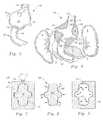
- FIG. 1is a perspective view of an anchor for a stent-graft or for use alone, according to this invention.
- FIG. 2is a full sectional front elevation view of that which is shown in FIG. 1 .
- FIG. 3is a perspective view of that which is shown in FIG. 1 after inflation of a void between an inner wall and an outer wall of the anchor.
- FIG. 4is a full sectional view of that which is shown in FIG. 3 and including associated patient geometry surrounding the anchor.
- FIG. 5is a perspective view of a combination anchor and stent-graft and with the anchor shown inflated.
- FIG. 6is a full sectional view of that which is shown in FIG. 5 shown within patient anatomy, and revealing the single walled structure of the stent-graft of this embodiment along with the double walled structure of the anchor of this embodiment.
- FIG. 7is a full sectional view of a cavity mold revealing one method for forming a single walled anchor and/or stent-graft according to this invention.
- FIG. 8is a full sectional view of a mandrel mold for use in the formation of a single walled anchor and/or stent-graft according to this invention.
- FIG. 9is a full sectional view of a rotating mold which can be used to form a single walled form of the anchor and/or stent-graft according to this invention.
- FIG. 10is a perspective view of a sacrificial mandrel for use in the formation of the double walled anchor of FIG. 1 .
- FIG. 11is a full sectional view of the sacrificial mandrel of FIG. 10 .
- FIG. 12is a perspective view of the sacrificial mandrel revealing cut lines for the cutting of the mandrel into sections, as a first step in a quilting process to provide interconnections between an inner wall and an outer wall of an anchor formed with the sacrificial mandrel shown therein.
- FIG. 13is a perspective view of that which is shown in FIG. 12 after cutting of the mandrel into sections and at the beginning of a coating process for individual sections of the sacrificial mandrel.
- FIG. 14is a perspective view of the sacrificial mandrel after having been reassembled and receiving a second coating to form the anchor with quilting included therein.
- FIG. 15is a perspective view of the anchor with internal quilting not visible within an interior thereof.
- FIG. 16is a full sectional top plan view of the anchor and mandrel together and revealing the orientation of the quilting interconnection between the inner wall and the outer wall and with the sacrificial mandrel still included therein.
- FIG. 17is a perspective view of a quilting mandrel which includes slits therein to form quilting interconnections between the inner wall and the outer wall of the anchor after the quilting mandrel is coating with the material forming the anchor.
- FIG. 18is a full sectional top plan view of a portion of that which is shown in FIG. 15 or 17 after removal of the sacrificial mandrel from within the voids of the anchor and revealing one orientation for the quilting between the inner wall and the outer wall of the anchor.
- FIG. 19is a top plan view similar to that which is shown in FIG. 18 , but illustrating thicker interconnections between the inner wall and the outer wall of the anchor.
- FIG. 20is a sectional top plan view similar to that which is shown in FIGS. 18 and 19 , but with interconnections with irregular widths forming quilting between the inner wall and the outer wall of the anchor.
- FIG. 21is a perspective view of the quilting mandrel with a liner included therein.
- FIGS. 22-24reveal a sequence of steps associated with the positioning of the liner within the mandrel or onto an anchor after formation of the anchor upon the mandrel, especially when a double wall of the liner material is desired to be provided adjacent the inner wall of the anchor.
- FIG. 25is a perspective view of the lumen shaper balloon according to the preferred embodiment for use in expanding the anchor of this invention.
- FIG. 26is a flow chart identifying the sequence of steps in the formation of a custom anchor, lumen shaper balloon and/or stent-graft with a particular geometry matching the particular luminal geometry of a patient to be treated with the device of this invention.
- FIGS. 27-32reveal steps in the process of delivering the anchor intraluminally to an implantation site.
- FIG. 33is a front elevation view in partial section of a human patient's aorta with a customized stent-graft with anchor according to this invention implanted therein.
- FIG. 34is a front elevation view in partial section of a patient's aorta with an anchor and stent-graft implanted therein especially at an aortic arch to treat an aneurysm therein.
- FIG. 35is a perspective view of a stent-graft with positioning anchor and with a portion of the stent-graft shown with a single walled and with a portion of the stent graft including separate toroidal sections in the form of double walls for at least a portion of the stent-graft.
- FIG. 36is a front elevation view of a patient with the stent-graft and anchor of FIG. 35 implanted within the patient and shown in full section.
- FIG. 37is a full sectional view of a portion of that which is shown in FIG. 36 adjacent where a single walled portion of the stent-graft is provided and where thrombus is present within an aortic aneurysm within the patient.
- FIG. 38is a perspective view of a custom configured combined stent-graft with positioning anchor for treatment of a particular patient's aortic aneurysm with a double walled anchor and single walled stent-graft indicated.
- FIG. 39is a front elevation view of a patient's anatomy with the stent-graft with positioning anchor of FIG. 38 implanted therein and shown in full section.
- FIG. 40is a top plan full sectional view of a portion of that which is shown in FIG. 39 revealing the position of the single walled stent-graft surrounded by thrombus within the aorta of the patient.
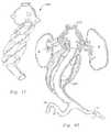
- FIG. 41is a perspective view of an alternative combination stent-graft with positioning anchor where both the positioning anchor and the stent-graft are formed together and are double walled in construction, having been custom manufactured to match a particular patient's arterial geometry.
- FIG. 42is a front elevation view of a patient's anatomy in section showing the stent-graft with positioning anchor of FIG. 41 in full section implanted therein, and particularly showing how stents are utilized to hold arms of the anchor in position relative to renal arteries of the patient and with the double walled stent-graft extending from the anchor.
- FIG. 43is a side elevation view of the aorta of the patient shown in FIG. 42 , and revealing how the superior messengerteric artery is located relative to one of the renal arteries.
- FIG. 44is a perspective view of the stent-graft of FIG. 41 shown from a side so that the arms of the anchor positioned for insertion within the messengerteric arteries are shown, and with radially expandable stents thereon for holding of the arms of the anchor in the desired positions, along with a stent for supporting an upper end of the anchor.
- reference numeral 10is directed to an anchor ( FIGS. 1-4 ) for use either alone or in combination with a stent-graft 40 to treat a damaged lumen such as an aorta A ( FIG. 4 ) by providing a primary fluid conduit 22 for bypass fluid flow through the damaged area.
- the anchor 10includes arms such as renal arms 16 , 18 which extend laterally for positioning within the renal arteries RA or other lateral arteries LA to assist in maintaining a position of the anchor 10 .
- the anchor 10can be inflated, such as with a fixation media M to secure the position of the anchor 10 within the aorta A or other body lumen.
- a stent-graft 40( FIG. 5 ) can be formed with or attached to the anchor 10 to further extend the primary fluid conduit for bypass fluid flow through the damaged portion of the aorta A.
- the anchor 10is preferably double walled including an inner wall 20 inboard of an outer wall 30 ( FIG. 2 ).
- a void 35is provided between the walls 20 , 30 .
- Arms 16 , 18preferably extend laterally from a primary fluid conduit 22 extending through the anchor 10 .
- the outer wall 30expands away from the inner wall 20 (along arrow B of FIG. 2 ) to fill a defect such as an aneurysm within the aorta A and to fix the position of the anchor 10 .
- the arms 16 , 18 of the anchor 10extend into lateral arteries such as the renal arteries RA to further assist in maintaining the desired position for the anchor 10 .
- the anchor 10can be utilized alone or can have a stent-graft 40 ( FIGS. 5 and 6 ) attached thereto or formed therewith to extend the primary fluid conduit 22 as needed to bypass damaged portions of the aorta A.
- the stent-graft 40can be single walled or double walled in form ( FIGS. 41-44 ) to help fill and support any aneurismal space which is desired to be filled within the aorta A or other body lumen in which the implant is positioned.
- the anchor 10preferably has a geometry provided to match a geometry of the patient at the implantation site for the anchor 10 .
- the anchor 10can either be manufactured to approximate typical patient geometry or custom manufactured as described in detail below, to match a particular patient's luminal anatomy at an implantation site.
- FIGS. 1-4depict an anchor 10 of somewhat simplified typical geometry for an anchor 10 configured for implantation at a junction between the aorta A of the patient and renal arteries RA leading to kidneys K of the patient.
- the anchor 10preferably has a particular geometry as follows.
- the anchor 10is preferably generally tubular in form surrounding a primary fluid conduit 22 between an upper end 12 and a lower end 14 .
- Multiple armspreferably surround lateral fluid conduits 24 extending away from the primary fluid conduit 22 .
- Such armscan include a superior messengerteric artery (SMA) arm 15 ( FIG. 3 ) and first and second renal arms 16 , 18 .
- SMAsuperior messengerteric artery
- These arms 15 , 16 , 18arc located where desired so that these arms 15 , 16 , 18 can extend at least partially into lateral arteries of the corresponding name within the patient.
- the anchor 10can be single walled to provide at least some of the desired function according to this invention, but is most preferably double walled in form. If the anchor 10 is single walled, it would typically be utilized in a patient which does not have an aneurysm or other defect at the location where the anchor 10 is to be implanted.
- the arms, such as the arms 15 , 16 , 18 of such a single walled anchorwould be positioned into corresponding arterial pathways extending from the aorta or other lumen into which the anchor is to be implanted. Most preferably, radially expandable stents would be located adjacent these arms and radially expanded to bring such arms 15 , 16 , 18 of the anchor 10 into intimate contact with these lateral arteries.
- a radial expandable stentcan be utilized adjacent the upper end 12 and/or the lower end 14 to hold the ends 12 , 14 of the anchor 10 securely in contact with the wall of the aorta A.
- additional attachment structurescould be utilized including sutures, staples, or other attachment structures known in the art to secure such a single walled anchor at the desired implantation site.
- Such a single walled anchor according to this inventionmight support a single walled stent-graft, or a double walled stent-graft which would typically pass through a portion of the aorta A or other body lumen which is damaged.
- Such a single walled stent-graftwould include a single wall which could merely extend the primary fluid channel away from the single walled anchor or could be provided as a separate piece configured to be attachable to such a single walled anchor, either outside of the patient or intraluminally during implantation of the single walled anchor and the stent-graft.
- the stent-graft 40would typically have an upper end 42 ( FIGS. 5 and 6 ) for formation with the anchor 10 or for attachment to the anchor 10 .
- the anchor 10is double walled, as particularly shown in FIGS. 1-4 , or with varying geometries to match a particular geometry of a particular patient at a specific desired implantation site, either within the aorta or in other arteries or body lumens where implantation is desired.
- the anchor 10is capable of undergoing an inflation and fixation procedure to assist in holding the anchor 10 in the desired implantation site location, and to fill an aneurysm or other defect space within the aorta A or other body lumen.
- a fixation matrix Mis delivered into the void 35 between the inner wall 20 and the outer wall 30 .
- the inner wall 20is preferably supported to prevent the inner wall 20 from collapsing inwardly into the primary fluid channel 22 .
- Such supportis preferably provided by a lumen shaper balloon which has been inflated inboard of the inner wall 20 .
- One such lumen shaper balloon 110is shown in FIG. 25 which could be utilized along with the anchor 10 of FIG. 1 during filling of the void 35 within the anchor 10 .
- the void 35can only expand to receive the fixation matrix M by having the artery wall 30 expand away from the inner wall 20 , along arrow B of FIG. 2 .
- This expansioncan both cause the outer wall 30 to expand into an aneurismal space or other defect and to enlarge the overall size of the anchor 10 to prevent the anchor 10 from moving away from its desired implantation site.
- the anchor 10has been expanded with the fixation matrix M so that the anchor 10 fills the space at the junction between the aorta A and the renal arteries RA such that the anchor 10 is securely held in position by the matching geometry between the anchor 10 and the patient geometry at that implantation site.
- a fixation methodologyis generally analogous to the means by which a glove remains upon the hand due to matching geometry between inboard and outboard structures.
- This fixation methodologycan be further enhanced by having the fixation media M formed of a material having a desired hardness which is either originally existing for the media M or which occurs in the media M after some transformation of the media M.
- the media Mcould be initially presented into the void 35 in the form of a gas which undergoes a phase change or other transformation into a liquid or solid form either through a temperature change, a chemical reaction with agents located within the void 35 or a sufficient time for a gaseous matrix to set into a liquid or solid form.
- the fixation media Mcan be originally delivered as a liquid which could either remain liquid or undergo some level of firmness enhancement, such as by setting into a gel, or hardening into a solid, either by temperature change, chemical reaction or other setting procedure.
- the media Mcould be delivered with multiple different components which would react together within the void 35 to solidify the media M within the void 35 to a desired level of firmness.
- Such firmnesscan both enhance the support with which the anchor 10 supports the wall of the aorta A, and can assist in holding the anchor 10 itself and any stent-graft 40 coupled to the anchor 10 fixed at the desired position within the patient.
- the anchor 10can be formed from a variety of different materials, either being formed from a single material or multiple different materials in combination.
- the material forming the anchor 10is at least one layer of material which is impervious to fluid migration therethrough, either directly or by the inclusion of a fluid barrier liner, such as adjacent the inner wall 20 of the anchor 10 .
- the anchor 10is formed from a layer of moldable material. Such a moldable material could be in the form of a polymeric hydrocarbon.
- the anchor 10 itself, and/or an accompanying stent-graft 40could be formed from parylene with a Dacron liner.
- the anchor 10could be provided without a liner or formed entirely out of Dacron. Other materials exhibiting bio-compatibility and sufficient preclusion of fluid migration therethrough would also be suitable for formation of the anchor 10 and stent-graft 40 according to this invention.
- the material forming the anchor 10preferably is flexible to facilitate collapsing of the anchor 10 and the stent-graft onto a catheter for intra-luminal implantation. Such flexibility also assists in allowing the catheter to follow curving arterial pathways during intra-luminal delivery to the implantation site. Additionally, the material forming the anchor 10 and the stent-graft 40 is preferably substantially inelastic, at least within an operating range of pressures and forces with which the material encounters during implantation and function according to this invention. Some elasticity could be accommodated, provided that such an elasticity does not interfere with the function of the anchor 10 and stent-graft 40 .
- the anchor 10 and other portions of the stent-graft 40can be formed of any suitable method which provides the anchor 10 with the desired geometry and from the materials having the desired functional characteristics to function properly according to this invention. If the anchor 10 is to be formed in a single walled manner, one option includes use of a two-piece cavity mold 50 ( FIG. 7 ), including an outer form 52 and an inner form 54 . A cavity 56 between the forms 52 , 54 is accessed through an entrance 58 for the material to enter the cavity mold 50 .
- Such formingcan generally be referred to as casting with the more specific manufacturing method utilizing such a mold including merely pouring the material into the mold, utilizing a vacuum to pull material into the mold, or utilizing some form of compression between the forms 52 , 54 or compression or pressurization of the material at the entrance 58 to flow the material forming the anchor 10 entirely into the cavity mold 50 .
- a mandrel mold 60which includes an inner mandrel 62 upon which a layer 64 of the material is deposited. Such material can be delivered, along arrow D of FIG. 8 , to form the layer 64 upon the mandrel mold 60 . Such delivery can occur by vapor deposition within a vacuum, dipping of the mandrel into fluid material for formation of the anchor 10 which can later harden, or with utilization of vacuum forming, such as where a layer of the material is sucked onto the inner mandrel 62 by small vacuum holes formed within the inner mandrel 62 .
- a rotating mold 70which includes an outer form 72 only, with an entrance 74 leading into a void within the outer form 72 .
- a layer 76is formed upon surfaces within the form 72 .
- This layer 76can be formed such as by filling the mold 70 with material through the entrance 74 and then spinning the mold 70 until a layer of the material with which the anchor is to be formed is applied to surfaces of the form 72 by forces applied along arrow E.
- vapor depositioncan occur within the mold 70 , gas pressure can be applied to blow the material against surfaces of the mold 70 , or a vacuum forming technique can be utilized where small vacuum ports are included within the outer form 72 extending into the cavity within the mold 70 to suck the material forming the layer 76 , typically originally provided in a solid sheet form, up against surfaces of the mold 70 .
- a vacuum forming techniquecan be utilized where small vacuum ports are included within the outer form 72 extending into the cavity within the mold 70 to suck the material forming the layer 76 , typically originally provided in a solid sheet form, up against surfaces of the mold 70 .
- FIGS. 7-9are suitable for forming a single walled anchor, most particularly. With some modification, some of these manufacturing methods could similarly be utilized for forming at least one of the walls of a double walled anchor 10 or for formation of both the inner wall 20 and the outer wall 30 of such an anchor 10 .
- a sacrificial mandrel 80which can be utilized according to a preferred embodiment to form the double walled anchor 10 of this invention.
- the sacrificial mandrel 80is essentially identical in size and contour to the void 35 of the anchor 10 , such as that shown in FIGS. 1 and 2 .
- Such a sacrificial mandrel 80can be manufactured utilizing various suitable casting or other forming techniques.
- the sacrificial mandrel 80would be formed of a material which can be readily destroyed for removal after formation of the double walled anchor 10 about the sacrificial mandrel 80 , leaving the void 35 within the anchor 10 .
- the sacrificial mandrel 80can be formed of a water soluble material, so that once it comes into contact with water it liquefies and can be removed leaving the void 35 within the anchor 10 .
- the sacrificial mandrel 80can be formed from a material which easily dissolves when an appropriate solvent is applied.
- the sacrificial mandrel 80could be formed of a foam material, such as Styrofoam, which would react with a solvent such as acetone to pass entirely into solution and be poured out of the void 35 in the form of a liquid.
- a solventsuch as acetone
- Such removal of the sacrificial mandrel 80would typically occur by forming a hole somewhere in the anchor 10 leading into the void 35 , or removal of the sacrificial mandrel 80 after it has been so dissolved.
- sacrificial mandrel 80from a material which can be readily oxidized, such as by combustion or otherwise gasified by a chemical reaction to allow the sacrificial mandrel 80 to be removed in the form of a gas out of the void 35 within the anchor 10 .
- the sacrificial mandrel 80could be formed from a solid material, such as a wax, which has a suitable melting point so that it can merely be heated until it changes phase into a liquid or gaseous form, to then be removed from the void 35 within the anchor 10 .
- the sacrificial mandrel 80could be formed from an easily fracturable solid material, such that sharp blows to the anchor 10 with the sacrificial mandrel 80 included therein would cause the sacrificial mandrel 80 to shatter into small solid pieces which could be removed from an appropriate hole leading into the void 35 within the anchor 10 .
- Such shatteringcould also be provided by appropriately tuned vibrations, or ultrasonic waves, which might be directed at the sacrificial mandrel through the walls 20 , 30 of the anchor 10 .
- the sacrificial mandrel 80be removed from the void 35 , it is also conceivable that the sacrificial mandrel 80 would remain in some form within the void 35 and be implanted along with the anchor 10 .
- the sacrificial mandrelis formed of a collapsible foam material which has any resiliency and shape memory, it could be collapsed upon a catheter with an appropriate sheath to hold the anchor lain its collapsed form. Once reaching the implantation site, the retraction of the sheath would cause such resilient foam to expand within the void 35 to the desired expanded position.
- additional materialcould be provided along with the material forming the sacrificial mandrel 80 , to further increases the size of the void 35 and/or to solidify the material forming the sacrificial mandrel 80 further, to enhance a firmness of the anchor 10 .
- the sacrificial mandrel 80would not necessarily be sacrificed, but rather remain in a position within the void 35 of the anchor 10 .
- first quilting methodallows for the providing of interconnections between the inner wall 20 and outer wall 30 of the anchor 10 or corresponding portions of a double walled stent-graft, such as the toroidal sections of the stent-graft shown in FIGS. 35 and 41-44 .
- the sacrificial mandrel 80can be sliced along lines dividing the sacrificial mandrel 80 into separate sections 82 ( FIG. 13 ). Such sections would be cut in orientations where the interconnection walls would be desired. Individual sections 82 would then be coated with a first coating 84 ( FIG.
- each section 82 of the sacrificial mandrel 80is entirely coated with the material with which the anchor 10 is to be formed.
- the sections 82would be reassembled ( FIG. 14 ) to again form the sacrificial mandrel 80 as it was originally constructed.
- a second coating 86is then applied to the exterior of the outer wall 30 and the interior of the inner wall 20 . This second coating 86 reattaches separate sections 82 of the sacrificial mandrel 80 back together.
- multiple separate chambersare included within the void 35 .
- the finished anchor/mandrel combination 90has a similar form ( FIG. 15 ) as the sacrificial mandrel 80 ( FIG. 10 ) and the desired finished construction for the anchor 10 ( FIG. 1 ).
- the multiple interconnectionsextend between the inner wall 20 and outer wall 30 , as particularly shown in the sectional view of FIG. 16 .
- the sectional configuration of the anchor 10can be as shown in FIG. 18 .
- the first coating 84FIG. 13
- thicker interconnectionsprovide wide quilting 106 between chambers in the void 35 ( FIG. 19 ).
- FIG. 17provides a quilting mandrel 100 similar to the sacrificial mandrel 80 ( FIG. 10 ) except that slits 102 are provided at various locations passing through the quilted mandrel 100 .
- These slits 102can have various different widths or tapering widths depending on whether thin quilting 105 ( FIG. 18 ) is desired or wide quilting 106 ( FIG. 19 ) is desired or whether tapered quilting 108 ( FIG. 20 ) is desired.
- the quilting mandrel 100When the quilting mandrel 100 is sprayed or vapor deposited with the material forming the anchor 10 , some of the material passes through the slits 102 to form the quilting between the inner wall 20 and the outer wall 30 of the anchor 10 .
- the void 35is provided with interconnection regions existing where the slits are provided within the quilting mandrel 100 .
- the anchor 10can include a liner 104 , such as adjacent the inner wall 20 .
- a liner 104is shown in FIG. 21 within the quilting mandrel 100 .
- This liner 104could be provided along with the quilting mandrel 100 so that formation of the walls 20 , 30 occurs with the liner 104 in position to bond the liner 104 to the material forming the walls 20 , 30 .
- the liner 104can be provided later after forming the inner wall 20 and outer wall 30 of the anchor 10 upon the sacrificial mandrel 80 or the quilting mandrel 100 .
- Such a liner 104can be attached to the anchor 10 before implantation of the anchor 10 or such a liner 104 can be provided during implantation or after implantation of the anchor 10 .
- a rod 109can be utilized to double back the liner 104 upon itself.
- a rod 109can be one portion of a circular tube such that a double walled liner 104 becomes a quadruple walled liner 104 , when the rod 109 is moved downwardly such as in FIGS. 22-24 , or can be changed from a single walled liner 104 to a double walled liner 104 if the rod 109 is in the form of a single rod 109 between two liners 104 .
- the liner 104can include holes therein adjacent where lateral arms are located within the anchor 10 , or can be continuous in those locations in a fashion precluding blood flow to lateral arteries, if desired. For instance, if a lateral artery is not particularly needed for blood flow, such a lateral artery can merely be utilized as an anchoring point for the arms of the anchor 10 , and not maintain blood flow therethrough. Preferably however, any liner 104 includes appropriate holes adjacent the arms of the anchor 10 so that blood flow is maintained through the lateral arteries adjacent where the anchor 10 is implanted.
- the shaper balloon 110is provided to expand the anchor 10 after translation of the anchor 10 with the catheter to the implantation site.
- the lumen shaper balloon 110is also provided to support the inner wall 20 of the anchor 10 during inflation of the void 35 in the anchor 10 with fixation media M.
- the lumen shaper balloon 110preferably includes a geometry matching generally that of the inner wall 20 of the anchor 10 .
- the lumen shaper balloon 110thus includes a top 112 spaced from a bottom 114 . Arms 116 extend away from the exterior surface of the shaper balloon 110 .
- the shaper balloon 110is preferably enclosed so that the top 112 and bottom 114 are enclosed with at least one access port for the delivery of an inflation fluid into the lumen shaper balloon 110 .
- knobs 118are located at the ends of each of the arms 115 which are enclosed to allow the lumen shaper balloon 110 to be inflated without any holes where leakage would occur. These knobs 118 preferably inflate to a larger diameter than adjacent arms.
- the knobs 118can be located adjacent where radially expandable stents are to be expanded between the anchor 10 and the lateral artery walls of the patient. The knobs 118 thus provide the radial force necessary to expand the radial expandable stent to the diameter desired.
- such radial expandable stentscan be delivered in a separate procedure after general positioning of the anchor 10 .
- the shaper balloon 110is custom manufactured to a geometry matching a contour of the particular patient's body lumen geometry where the anchor 10 is to be implanted.
- a custom shaper balloon 110is provided particularly adapted for expansion, inflation and proper positioning of the custom anchor 10 at the implantation site.
- the lumen shaper balloon 110would typically be a single walled structure, such that the manufacturing techniques particularly illustrated in FIGS. 7-9 and discussed in detail above would be suitable for formation of the lumen shaper balloon 110 .
- patient imaging informationin the form of X-rays, computer tomography (CT) scans, ultrasound data, magnetic resonance imaging (MRI) data or other imaging data are acquired and converted into a data file such as that which can be read by a computer aided drafting (CAD) file or other corresponding data coding methodology.
- CTcomputer tomography
- MRImagnetic resonance imaging
- This imaging informationcan be viewed, such as by a physician or other medical treatment planners to determine how best to treat any defects in the body lumens being imaged.
- the treatment plannercan construct a desired geometry for the anchor 10 and/or stent-graft 40 which would match the particular patient's luminal geometry at the treatment site. Some or all of this process of constructing a desired geometry for the anchor 10 and/or the stent-graft 40 could similarly occur in an automated fashion by a computer recognizing the geometry of the patient's body lumen and taking appropriate measurements to construct a desirable anchor 10 and/or stent-graft 40 .
- Data files corresponding with the geometry of the desired anchor 10 and desired lumen shaper balloon 110are then sent to a rapid prototyping (RP) machine, such as that provided by Z-Corp or 3-D Systems.
- the rapid prototyping machinethen creates actual three-dimensional models, preferably of full size, for the anchor 10 and the lumen shaper balloon 110 .
- These 3-D models of the anchor 10 and lumen shaper balloon 110can then either be used directly or indirectly to form mandrels or other molds which will then be used in formation of the final anchor 10 and lumen shaper balloon 110 .
- the mandrelis removed as is discussed in detail above to provide voids 35 where desired within the anchor 10 .
- the final shaper balloon 110 and anchor 10can then be collapsed upon a catheter or other deployment device for use in the implantation procedure, to be delivered to the implantation site.
- a lateral viewis provided with the primary fluid conduit extending vertically in the form of a human patient's aorta and with lateral arteries in the form of the superior messengerteric artery (SMA) and a second lateral artery LA, such as the inferior messengerteric artery.
- SMAsuperior messengerteric artery
- LAsecond lateral artery LA
- a delivery catheter 120which includes the shaper balloon 160 collapsed upon the delivery catheter 120 and with the anchor 150 overlying and collapsed upon the shaper balloon 160 .
- a sheath 140overlies the anchor 150 and shaper balloon 160 to assist in holding the shaper balloon 160 and anchor 150 in their collapsed configuration.
- the delivery catheter 120can then be fed through an insertion site, such as in the femoral artery of one of the legs of the patient, up to the aorta A or other implantation site.
- a guide wire 122is preferably provided to assist in steering the delivery catheter 120 along the desired arterial pathway up to the aorta A.
- a seal balloon 130is provided near a tip of the delivery catheter 120 .
- This seal balloon 130can be initially inflated, such as through a fluid delivery conduit within the delivery catheter 120 and with an outlet at the seal balloon 130 .
- the seal balloon 130can thus be expanded to block off the aorta A.
- a tip of the delivery catheter 120includes a bypass inlet 124 to a hollow center of the delivery catheter 120 , or other pathway extending to the bypass outlet 126 . In this way, blood flow F can be diverted through the delivery catheter 120 during the positioning, expansion and inflation procedure for the anchor 150 .
- the shaper balloon 160is then inflated by delivery of an appropriate inflation fluid into the shaper balloon 160 .
- Thiscauses the anchor 150 to be expanded to its fully expanded (but uninflated) form ( FIG. 29 ).
- arms 152 in the anchor 150begin to protrude with the assistance of the arms 162 of the shaper balloon 160 .
- the delivery catheter 120can be further rotated if necessary to make sure that the arms 152 are oriented where desired so that the arms 152 feed into the lateral artery LA and superior messengerteric artery SMA for proper positioning of the anchor 150 .
- the shaper balloon 160has been fully inflated, the entire aneurysm X has not typically been entirely filled. However, the arms 152 , of the anchor 150 should extend into the lateral arteries LA extending off of the aorta A.
- a collar 170can be provided within the anchor 150 which is in the form of a separate void which can be initially filled to provide added structure to the anchor 150 and to further assist in preventing the anchor 150 from slipping within the aorta A. Such filling of the collar 170 can occur through a filler tube 172 leading to the collar 170 .
- Fixation media Mis then delivered through the media delivery tube 180 ( FIG. 31 ) to expand the outer wall 156 away from the inner wall 154 and fill the void 155 between these walls 154 , 156 . As discussed in detail above, the fixation media M is then allowed to harden to the desired firmness according to the type of fixation media M utilized. If desired, radial expandable stents can be radial expanded within the arms 152 of the anchor 150 to secure the arms 152 where desired within lateral arteries, and/or adjacent an upper end and/or a lower end of the anchor 150 .
- the lumen shaper balloonwhich has remained inflated to ensure that the primary fluid conduit through the anchor 150 remains fully open during setting and filling of the void 155 with the media M, can be deflated along with the seal balloon 130 .
- the delivery catheter 120 , fill balloon 130 and lumen shaper balloon 160can then be retracted out of the anchor 150 .
- portions of a stent-graftarc coupled to the anchor 150 , they can be inflated before movement of the delivery catheter 120 , or with a balloon such as the seal balloon 130 utilized to expand the stent-graft as the delivery catheter 120 is retracted. Once the delivery catheter 120 and lumen shaper balloon 160 has been removed, blood flow F′ occurs through the anchor 150 and with blood allowed to flow through the lateral arteries coupled to the aorta A at the implantation site.
- a similar procedurecould be utilized for delivery of an anchor to the aortic arch, or to a location above the renal arteries, or to a location below the renal arteries, depending on the particular treatment plan indicated for the patient's condition.
- An analogous delivery procedurewould be utilized for the expansion and inflation of a double walled stent-graft according to this invention with the exception that no arms would be included which would require positioning into lateral arteries.
- Such a stent-graftcan be provided along with the anchor or implanted in a separate follow-up procedure after positioning of the anchor.
- an aneurysm Xis presented within an aorta A which is primarily below the renal arteries RA and above the iliac arteries IA, but close to the iliac arteries IA.
- This aneurysm Xincludes a significant amount of thrombus T in at least one portion of the aneurysm X.
- a stent-graft with renal anchor 200is custom manufactured to have a geometry similar to that depicted in FIG. 33 .
- the anchor portionis generally in the form of a single walled anchor which includes stents 210 in arms of the anchor which extend into the renal arteries, the superior messengerteric artery SMA and other lateral arteries LA. Additional stents 210 support upper and lower ends of the anchor adjacent walls of the aorta A.
- a series of toroidsare manufactured along with the stent-graft portion of the implant 200 . These toroids are generally similar to those shown in the stent-graft with positioning anchor 600 of FIGS. 41-44 . Once these toroidal sections have been filled with fixation media M, they fill portions of the aneurysm X which are not already filled with thrombus T. A final channel is provided which extends through the aneurysm X down to the iliac arteries IA. In this case, the stent-graft portion splits into two separate channels to feed each of the iliac arteries IA separately. Stents can be provided at the ends of these separate channels to support the lower most ends of the implant 200 .
- a stent-graft with aortic arch anchor 300is depicted.
- the patient's aortic arch and portions of the aorta above the renal arteriesincludes an aneurysm therein.
- the position of the patient's heart His shown in broken lines for reference.
- the aneurysm Xboth exists within the aortic arch and below the aortic arch.
- An anchoris provided which includes two walls so that the anchor portion of the implant can be expanded, as well as toroidal sections on the stent-graft portion of the implant 300 .
- the aortic arch anchoris custom manufactured to have lateral artery arms positioned where desired to match the particular patient geometry, so that the aortic arch anchor, once expanded, will securely hold both the anchor and the stent-graft in the desired position.
- Media Mfills both the void within the aortic arch anchor and in the stent-graft, extending from the aortic arch anchor to fill excess space within the aneurysm X.
- the patienthas an aortic aneurysm which includes both a junction between the aorta and the renal arteries and an aneurysm X extending down to near the iliac arteries IA.
- a sufficient amount of thrombus Texists in a midpoint of the aneurysm that the stent-graft portion of the proposed implant 400 need only be a single walled stent-graft at upper portions thereof.
- Stent 410supports upper end of implant 400 adjacent walls of the aorta A.
- Lower portions of the stent-graftinclude toroidal Tillable sections so that the stent-graft is double walled in this lower region.
- the anchor portion of the implant 400is double walled, similar to the embodiment of FIGS. 3 and 4 .
- This exampleillustrates how portions of the aneurysm X can be filled with media within the anchor and portions of the aneurysm X can be filled with media through the toroids on the stent-graft, with still further portions of the aneurysm X filled with the thrombus T already existing within the aneurysm X, and with potentially other portions of the aneurysm X remaining unfilled where it is deemed that such a void is not disadvantageous.
- the aneurysmstops sufficiently short of the iliac arteries IA.
- FIG. 37provides a cross-section of a portion of the stent-graft which is single walled, and illustrating how the thrombus T can act to support the stent-graft within the aorta A.
- FIGS. 38-40provide a fourth example for the function of the invention of this application.
- the patienthas an aneurysm with a significant amount of thrombus T in the lower portion thereof, but without a significant amount of thrombus near the junction with the renal arteries RA.
- a stent-graft with positioning anchor 500is manufactured as shown in FIG. 38 .
- This stent-graft with positioning anchoris configured to utilize the renal arteries primarily for anchoring of the anchor and the stent-graft portions of the implant 500 .
- Stent 510supports upper end of anchor 500 adjacent walls of the aorta A.
- Fixation media Mis utilized to expand the anchor portion of the implant 500 to fill the void adjacent the renal arteries RA. Because lower portions of the aneurysm X include a significant amount of thrombus T which is already effectively positioned to support the stent-graft portion of the implant 500 , the stent-graft portion can be merely a single walled stent-graft extending entirely down from the anchor portion of the implant 500 , without any toroidal sections which require any filling. In this example the stent-graft is shown with dual tubes at lower ends extending into each of the iliac arteries IA. FIG. 40 again illustrates a cross-section where the stent-graft portion of the implant 500 is supported by thrombus T.
- FIGS. 41-44show a fifth example where an implant 600 in the form of custom stent-graft with renal artery anchor is provided according to this invention.
- a stent-graft with positioning anchoris custom manufactured to match the patient's particular geometry, in a situation where an aneurysm X exists both at the junction of the aorta with the renal arteries RA and with the aneurysm X extending below the junction with the renal arteries RA.
- Insufficient thrombus Texists to provide adequate support for the stent-graft portion extending below the anchor portion of the implant 600 .
- a series of toroidsare included on the stent-graft portion which can be separately filled with fixation media M similar to the inflation of the anchor portion of the implant 600 .
- FIG. 42radially expandable stents 610 are shown to illustrate how the anchor portion of the implant 600 is held both within the renal arteries RA and within the aorta A ( FIG. 42 ).
- FIG. 43clearly illustrates the geometry of the aneurysm X from a side view with FIG. 44 showing the implant 600 from a side view to further illustrate the positioning of stents 610 , particularly for use in holding the various arms of the anchor portion of the implant 600 within lateral arteries to secure the anchor portion of the implant 600 in the desired implantation position within the patient.
Landscapes
- Health & Medical Sciences (AREA)
- Engineering & Computer Science (AREA)
- Biomedical Technology (AREA)
- Heart & Thoracic Surgery (AREA)
- Oral & Maxillofacial Surgery (AREA)
- Transplantation (AREA)
- Cardiology (AREA)
- Vascular Medicine (AREA)
- Life Sciences & Earth Sciences (AREA)
- Animal Behavior & Ethology (AREA)
- General Health & Medical Sciences (AREA)
- Public Health (AREA)
- Veterinary Medicine (AREA)
- Pulmonology (AREA)
- Gastroenterology & Hepatology (AREA)
- Prostheses (AREA)
Abstract
Description
Claims (15)
Priority Applications (1)
| Application Number | Priority Date | Filing Date | Title |
|---|---|---|---|
| US14/697,433US9814612B2 (en) | 2002-09-20 | 2015-10-21 | Stent-graft with positioning anchor |
Applications Claiming Priority (4)
| Application Number | Priority Date | Filing Date | Title |
|---|---|---|---|
| US41250102P | 2002-09-20 | 2002-09-20 | |
| US10/668,901US20040116997A1 (en) | 2002-09-20 | 2003-09-22 | Stent-graft with positioning anchor |
| US11/876,458US9113999B2 (en) | 2002-09-20 | 2007-10-22 | Methods for deploying a positioning anchor with a stent-graft |
| US14/697,433US9814612B2 (en) | 2002-09-20 | 2015-10-21 | Stent-graft with positioning anchor |
Related Parent Applications (1)
| Application Number | Title | Priority Date | Filing Date |
|---|---|---|---|
| US11/876,458DivisionUS9113999B2 (en) | 2002-09-20 | 2007-10-22 | Methods for deploying a positioning anchor with a stent-graft |
Publications (2)
| Publication Number | Publication Date |
|---|---|
| US20160030215A1 US20160030215A1 (en) | 2016-02-04 |
| US9814612B2true US9814612B2 (en) | 2017-11-14 |
Family
ID=32030890
Family Applications (3)
| Application Number | Title | Priority Date | Filing Date |
|---|---|---|---|
| US10/668,901AbandonedUS20040116997A1 (en) | 2002-09-20 | 2003-09-22 | Stent-graft with positioning anchor |
| US11/876,458Expired - Fee RelatedUS9113999B2 (en) | 2002-09-20 | 2007-10-22 | Methods for deploying a positioning anchor with a stent-graft |
| US14/697,433Expired - Fee RelatedUS9814612B2 (en) | 2002-09-20 | 2015-10-21 | Stent-graft with positioning anchor |
Family Applications Before (2)
| Application Number | Title | Priority Date | Filing Date |
|---|---|---|---|
| US10/668,901AbandonedUS20040116997A1 (en) | 2002-09-20 | 2003-09-22 | Stent-graft with positioning anchor |
| US11/876,458Expired - Fee RelatedUS9113999B2 (en) | 2002-09-20 | 2007-10-22 | Methods for deploying a positioning anchor with a stent-graft |
Country Status (4)
| Country | Link |
|---|---|
| US (3) | US20040116997A1 (en) |
| EP (1) | EP1542616B1 (en) |
| AU (1) | AU2003272682C1 (en) |
| WO (1) | WO2004026183A2 (en) |
Families Citing this family (126)
| Publication number | Priority date | Publication date | Assignee | Title |
|---|---|---|---|---|
| US20060292206A1 (en)* | 2001-11-26 | 2006-12-28 | Kim Steven W | Devices and methods for treatment of vascular aneurysms |
| US7147661B2 (en) | 2001-12-20 | 2006-12-12 | Boston Scientific Santa Rosa Corp. | Radially expandable stent |
| US6793678B2 (en) | 2002-06-27 | 2004-09-21 | Depuy Acromed, Inc. | Prosthetic intervertebral motion disc having dampening |
| EP1542616B1 (en) | 2002-09-20 | 2015-04-22 | Endologix, Inc. | Stent-graft with positioning anchor |
| US7481821B2 (en) | 2002-11-12 | 2009-01-27 | Thomas J. Fogarty | Embolization device and a method of using the same |
| US20040260382A1 (en) | 2003-02-12 | 2004-12-23 | Fogarty Thomas J. | Intravascular implants and methods of using the same |
| AU2004212942A1 (en) | 2003-02-14 | 2004-09-02 | Depuy Spine, Inc. | In-situ formed intervertebral fusion device |
| US20040267367A1 (en) | 2003-06-30 | 2004-12-30 | Depuy Acromed, Inc | Intervertebral implant with conformable endplate |
| US20050015110A1 (en) | 2003-07-18 | 2005-01-20 | Fogarty Thomas J. | Embolization device and a method of using the same |
| CA2563426C (en) | 2004-05-05 | 2013-12-24 | Direct Flow Medical, Inc. | Unstented heart valve with formed in place support structure |
| ATE540640T1 (en) | 2004-07-22 | 2012-01-15 | Nellix Inc | SYSTEMS FOR THE TREATMENT OF ENDOVASCULAR ANEURYSMS |
| US8048145B2 (en) | 2004-07-22 | 2011-11-01 | Endologix, Inc. | Graft systems having filling structures supported by scaffolds and methods for their use |
| US8066759B2 (en)* | 2005-02-04 | 2011-11-29 | Boston Scientific Scimed, Inc. | Resonator for medical device |
| CA2599460A1 (en)* | 2005-04-28 | 2006-11-02 | Nellix, Inc. | Graft systems having filling structures supported by scaffolds and methods for their use |
| US7595469B2 (en)* | 2005-05-24 | 2009-09-29 | Boston Scientific Scimed, Inc. | Resonator for medical device |
| CA2610669A1 (en)* | 2005-06-07 | 2006-12-14 | Direct Flow Medical, Inc. | Stentless aortic valve replacement with high radial strength |
| JP2009500121A (en) | 2005-07-07 | 2009-01-08 | ネリックス・インコーポレーテッド | System and method for treatment of an intraluminal aneurysm |
| US7279664B2 (en)* | 2005-07-26 | 2007-10-09 | Boston Scientific Scimed, Inc. | Resonator for medical device |
| US7304277B2 (en)* | 2005-08-23 | 2007-12-04 | Boston Scientific Scimed, Inc | Resonator with adjustable capacitor for medical device |
| US7524282B2 (en)* | 2005-08-29 | 2009-04-28 | Boston Scientific Scimed, Inc. | Cardiac sleeve apparatus, system and method of use |
| US7423496B2 (en)* | 2005-11-09 | 2008-09-09 | Boston Scientific Scimed, Inc. | Resonator with adjustable capacitance for medical device |
| US20070150041A1 (en)* | 2005-12-22 | 2007-06-28 | Nellix, Inc. | Methods and systems for aneurysm treatment using filling structures |
| US20070150052A1 (en)* | 2005-12-23 | 2007-06-28 | Santilli Albert N | Manufacture of prosthetic tissue heart components |
| GB0603685D0 (en)* | 2006-02-23 | 2006-04-05 | Angiomed Ag | Vascular prosthesis for aneurysms, set of vascular prostheses, method for manufacturing a vascular prosthesis and method for inserting a vascular prosthesis |
| US8828074B2 (en)* | 2006-04-21 | 2014-09-09 | Medtronic Vascular, Inc. | Stent graft having short tube graft for branch vessel |
| EP2015846A2 (en)* | 2006-04-24 | 2009-01-21 | Ekos Corporation | Ultrasound therapy system |
| US20090209988A1 (en)* | 2006-05-17 | 2009-08-20 | Syntach Ag | Patient configured device, a kit and a method for treatment of disorders in the heart rhythm regulation system |
| US7790273B2 (en)* | 2006-05-24 | 2010-09-07 | Nellix, Inc. | Material for creating multi-layered films and methods for making the same |
| US20080172073A1 (en)* | 2006-06-16 | 2008-07-17 | Searete Llc, A Limited Liability Corporation Of The State Of Delaware | Active blood vessel sleeve |
| US8551155B2 (en)* | 2006-06-16 | 2013-10-08 | The Invention Science Fund I, Llc | Stent customization system and method |
| US20080133040A1 (en)* | 2006-06-16 | 2008-06-05 | Searete Llc, A Limited Liability Corporation Of The State Of Delaware | Methods and systems for specifying a blood vessel sleeve |
| US8550344B2 (en)* | 2006-06-16 | 2013-10-08 | The Invention Science Fund I, Llc | Specialty stents with flow control features or the like |
| US8034110B2 (en) | 2006-07-31 | 2011-10-11 | Depuy Spine, Inc. | Spinal fusion implant |
| GB0617219D0 (en) | 2006-08-31 | 2006-10-11 | Barts & London Nhs Trust | Blood vessel prosthesis and delivery apparatus |
| US7935144B2 (en) | 2006-10-19 | 2011-05-03 | Direct Flow Medical, Inc. | Profile reduction of valve implant |
| US8133213B2 (en) | 2006-10-19 | 2012-03-13 | Direct Flow Medical, Inc. | Catheter guidance through a calcified aortic valve |
| WO2008070863A2 (en) | 2006-12-07 | 2008-06-12 | Interventional Spine, Inc. | Intervertebral implant |
| US20080188923A1 (en)* | 2007-02-01 | 2008-08-07 | Jack Fa-De Chu | Endovascular devices to protect aneurysmal wall |
| US20080228259A1 (en)* | 2007-03-16 | 2008-09-18 | Jack Fa-De Chu | Endovascular devices and methods to protect aneurysmal wall |
| US8900307B2 (en) | 2007-06-26 | 2014-12-02 | DePuy Synthes Products, LLC | Highly lordosed fusion cage |
| WO2009026563A2 (en)* | 2007-08-23 | 2009-02-26 | Direct Flow Medical, Inc. | Translumenally implantable heart valve with formed in place support |
| US8663309B2 (en) | 2007-09-26 | 2014-03-04 | Trivascular, Inc. | Asymmetric stent apparatus and method |
| US8066755B2 (en) | 2007-09-26 | 2011-11-29 | Trivascular, Inc. | System and method of pivoted stent deployment |
| US8226701B2 (en) | 2007-09-26 | 2012-07-24 | Trivascular, Inc. | Stent and delivery system for deployment thereof |
| US10159557B2 (en) | 2007-10-04 | 2018-12-25 | Trivascular, Inc. | Modular vascular graft for low profile percutaneous delivery |
| US8083789B2 (en) | 2007-11-16 | 2011-12-27 | Trivascular, Inc. | Securement assembly and method for expandable endovascular device |
| US8328861B2 (en) | 2007-11-16 | 2012-12-11 | Trivascular, Inc. | Delivery system and method for bifurcated graft |
| US8795577B2 (en) | 2007-11-30 | 2014-08-05 | Cook Medical Technologies Llc | Needle-to-needle electrospinning |
| US8128677B2 (en) | 2007-12-12 | 2012-03-06 | Intact Vascular LLC | Device and method for tacking plaque to a blood vessel wall |
| US10166127B2 (en) | 2007-12-12 | 2019-01-01 | Intact Vascular, Inc. | Endoluminal device and method |
| US9375327B2 (en) | 2007-12-12 | 2016-06-28 | Intact Vascular, Inc. | Endovascular implant |
| US10022250B2 (en) | 2007-12-12 | 2018-07-17 | Intact Vascular, Inc. | Deployment device for placement of multiple intraluminal surgical staples |
| US7896911B2 (en) | 2007-12-12 | 2011-03-01 | Innovasc Llc | Device and method for tacking plaque to blood vessel wall |
| US9603730B2 (en) | 2007-12-12 | 2017-03-28 | Intact Vascular, Inc. | Endoluminal device and method |
| EP2237748B1 (en) | 2008-01-17 | 2012-09-05 | Synthes GmbH | An expandable intervertebral implant |
| EP2242454A1 (en)* | 2008-02-13 | 2010-10-27 | Nellix, Inc. | Graft endoframe having axially variable characteristics |
| GB0803302D0 (en)* | 2008-02-22 | 2008-04-02 | Barts & London Nhs Trust | Blood vessel prosthesis and delivery apparatus |
| US8936641B2 (en) | 2008-04-05 | 2015-01-20 | DePuy Synthes Products, LLC | Expandable intervertebral implant |
| EP2278939B1 (en) | 2008-04-25 | 2021-04-14 | Endologix LLC | Stent graft delivery system |
| CA2726452A1 (en)* | 2008-06-04 | 2009-12-30 | Nellix, Inc. | Docking apparatus and methods of use |
| EP2299931B1 (en) | 2008-06-04 | 2020-01-08 | Endologix, Inc. | Sealing apparatus |
| US20100016833A1 (en)* | 2008-07-15 | 2010-01-21 | Ogle Matthew F | Devices for the Treatment of Vascular Aneurysm |
| US10045868B2 (en)* | 2009-03-04 | 2018-08-14 | W. L. Gore & Associates Inc. | Atraumatic vascular graft removal sheath |
| US9526620B2 (en) | 2009-03-30 | 2016-12-27 | DePuy Synthes Products, Inc. | Zero profile spinal fusion cage |
| US10772717B2 (en) | 2009-05-01 | 2020-09-15 | Endologix, Inc. | Percutaneous method and device to treat dissections |
| JP2012525239A (en) | 2009-05-01 | 2012-10-22 | エンドロジックス、インク | Transcutaneous methods and devices for treating dissociation (priority information and incorporation by reference) |
| EP2435677A4 (en)* | 2009-05-26 | 2014-12-03 | Inentec Inc | Regenerator for syngas cleanup and energy recovery in gasifier systems |
| WO2011017123A2 (en) | 2009-07-27 | 2011-02-10 | Endologix, Inc. | Stent graft |
| US8444624B2 (en)* | 2009-10-19 | 2013-05-21 | Vatrix Medical, Inc. | Vascular medical devices with sealing elements and procedures for the treatment of isolated vessel sections |
| US8637109B2 (en)* | 2009-12-03 | 2014-01-28 | Cook Medical Technologies Llc | Manufacturing methods for covering endoluminal prostheses |
| US9168138B2 (en) | 2009-12-09 | 2015-10-27 | DePuy Synthes Products, Inc. | Aspirating implants and method of bony regeneration |
| US9393129B2 (en) | 2009-12-10 | 2016-07-19 | DePuy Synthes Products, Inc. | Bellows-like expandable interbody fusion cage |
| US20110276078A1 (en) | 2009-12-30 | 2011-11-10 | Nellix, Inc. | Filling structure for a graft system and methods of use |
| US9433501B2 (en) | 2010-05-19 | 2016-09-06 | Direct Flow Medical, Inc. | Inflation media for implants |
| WO2011153110A2 (en)* | 2010-05-29 | 2011-12-08 | Innovasc Llc | Stent device having focal elevating elements for minimal surface area contact with lumen walls |
| US9907560B2 (en) | 2010-06-24 | 2018-03-06 | DePuy Synthes Products, Inc. | Flexible vertebral body shavers |
| US8979860B2 (en) | 2010-06-24 | 2015-03-17 | DePuy Synthes Products. LLC | Enhanced cage insertion device |
| US8623091B2 (en) | 2010-06-29 | 2014-01-07 | DePuy Synthes Products, LLC | Distractible intervertebral implant |
| US9402732B2 (en) | 2010-10-11 | 2016-08-02 | DePuy Synthes Products, Inc. | Expandable interspinous process spacer implant |
| US9393100B2 (en) | 2010-11-17 | 2016-07-19 | Endologix, Inc. | Devices and methods to treat vascular dissections |
| US8801768B2 (en) | 2011-01-21 | 2014-08-12 | Endologix, Inc. | Graft systems having semi-permeable filling structures and methods for their use |
| EP2693980B1 (en) | 2011-04-06 | 2022-07-13 | Endologix LLC | System for endovascular aneurysm treatment |
| US10285831B2 (en) | 2011-06-03 | 2019-05-14 | Intact Vascular, Inc. | Endovascular implant |
| US20150127031A1 (en)* | 2011-08-26 | 2015-05-07 | EBM Corporation | Bloodstream simulation system for simulating blood vessel treatment effect, method therefor, and computer software program |
| US20130289690A1 (en) | 2011-11-01 | 2013-10-31 | Hira V. Thapliyal | Personalized prosthesis and methods of use |
| US9175427B2 (en) | 2011-11-14 | 2015-11-03 | Cook Medical Technologies Llc | Electrospun patterned stent graft covering |
| CN110464520A (en) | 2012-01-25 | 2019-11-19 | 因特脉管有限公司 | Intracavitary unit and method |
| US8992595B2 (en) | 2012-04-04 | 2015-03-31 | Trivascular, Inc. | Durable stent graft with tapered struts and stable delivery methods and devices |
| US9498363B2 (en) | 2012-04-06 | 2016-11-22 | Trivascular, Inc. | Delivery catheter for endovascular device |
| US9811613B2 (en)* | 2012-05-01 | 2017-11-07 | University Of Washington Through Its Center For Commercialization | Fenestration template for endovascular repair of aortic aneurysms |
| US9283078B2 (en) | 2012-09-21 | 2016-03-15 | Materialise N.V. | Patient-specific intraluminal implants |
| JP6270856B2 (en)* | 2012-10-05 | 2018-01-31 | マテリアライズ エン.フェー. | Customized aortic stent device and method of making same |
| US10154918B2 (en) | 2012-12-28 | 2018-12-18 | Cook Medical Technologies Llc | Endoluminal prosthesis with fiber matrix |
| US9717601B2 (en) | 2013-02-28 | 2017-08-01 | DePuy Synthes Products, Inc. | Expandable intervertebral implant, system, kit and method |
| US9522070B2 (en) | 2013-03-07 | 2016-12-20 | Interventional Spine, Inc. | Intervertebral implant |
| BR112015022688B1 (en) | 2013-03-14 | 2020-10-06 | Endologix, Inc. | METHOD FOR FORMING A MATERIAL IN SITU THROUGH INCREASING THE VOLUME OF AN EXPANDABLE MEMBER OF A MEDICAL DEVICE |
| DE102013103176A1 (en)* | 2013-03-28 | 2014-10-02 | Acandis Gmbh & Co. Kg | Method for producing a patient-specific implant |
| US10285829B2 (en)* | 2014-05-12 | 2019-05-14 | 3D Systems, Inc. | System and method for fabricating custom medical implant devices |
| DE102014113836B4 (en)* | 2014-09-24 | 2021-05-06 | Acandis Gmbh | Method for producing a patient-specific, endovascular implant |
| US10172612B2 (en) | 2015-01-21 | 2019-01-08 | Covidien Lp | Surgical instruments with force applier and methods of use |
| US9375336B1 (en) | 2015-01-29 | 2016-06-28 | Intact Vascular, Inc. | Delivery device and method of delivery |
| US9433520B2 (en) | 2015-01-29 | 2016-09-06 | Intact Vascular, Inc. | Delivery device and method of delivery |
| US11426290B2 (en) | 2015-03-06 | 2022-08-30 | DePuy Synthes Products, Inc. | Expandable intervertebral implant, system, kit and method |
| US10575975B2 (en) | 2015-04-22 | 2020-03-03 | Aneumed, Inc. | Personalized prosthesis and methods of deployment |
| US20170019895A1 (en)* | 2015-07-17 | 2017-01-19 | Qualcomm Technologies International, Ltd. | Signaling method for improved ofdma-based data ack/ba frame exchange in wireless network systems |
| US10993824B2 (en) | 2016-01-01 | 2021-05-04 | Intact Vascular, Inc. | Delivery device and method of delivery |
| WO2017187174A1 (en)* | 2016-04-26 | 2017-11-02 | Cambridge Enterprise Limited | Patient-specific endovascular devices |
| EP3474784A2 (en) | 2016-06-28 | 2019-05-01 | Eit Emerging Implant Technologies GmbH | Expandable and angularly adjustable intervertebral cages with articulating joint |
| US11510788B2 (en) | 2016-06-28 | 2022-11-29 | Eit Emerging Implant Technologies Gmbh | Expandable, angularly adjustable intervertebral cages |
| WO2018045097A1 (en)* | 2016-08-31 | 2018-03-08 | Endologix, Inc. | Systems and methods with stent and filling structure |
| US10973526B2 (en)* | 2016-10-05 | 2021-04-13 | Arizona Board Of Regents On Behalf Of Arizona State University | Customized endovascular devices and methods pertaining thereto |
| US10888433B2 (en) | 2016-12-14 | 2021-01-12 | DePuy Synthes Products, Inc. | Intervertebral implant inserter and related methods |
| US10398563B2 (en) | 2017-05-08 | 2019-09-03 | Medos International Sarl | Expandable cage |
| US11344424B2 (en) | 2017-06-14 | 2022-05-31 | Medos International Sarl | Expandable intervertebral implant and related methods |
| US10940016B2 (en) | 2017-07-05 | 2021-03-09 | Medos International Sarl | Expandable intervertebral fusion cage |
| US11660218B2 (en) | 2017-07-26 | 2023-05-30 | Intact Vascular, Inc. | Delivery device and method of delivery |
| EP3784169A4 (en)* | 2018-04-23 | 2022-02-16 | Endologix LLC | Modulation of inflammatory response following endovascular treatment |
| CN112292221B (en) | 2018-05-21 | 2023-06-13 | 悉尼大学 | Method for producing castings |
| US11446156B2 (en) | 2018-10-25 | 2022-09-20 | Medos International Sarl | Expandable intervertebral implant, inserter instrument, and related methods |
| FR3091483B1 (en) | 2019-01-03 | 2023-05-12 | Ass Marie Lannelongue | Automated stent manufacturing process |
| FI3941392T3 (en) | 2019-03-20 | 2025-07-28 | Inqb8 Medical Tech Llc | Aortic dissection implant |
| US11426286B2 (en) | 2020-03-06 | 2022-08-30 | Eit Emerging Implant Technologies Gmbh | Expandable intervertebral implant |
| KR20230065992A (en) | 2020-09-07 | 2023-05-12 | 프론티어 바이오 코포레이션 | Systems and methods for creating objects with conduits for specific vascular applications |
| US11850160B2 (en) | 2021-03-26 | 2023-12-26 | Medos International Sarl | Expandable lordotic intervertebral fusion cage |
| US11752009B2 (en) | 2021-04-06 | 2023-09-12 | Medos International Sarl | Expandable intervertebral fusion cage |
| US12090064B2 (en) | 2022-03-01 | 2024-09-17 | Medos International Sarl | Stabilization members for expandable intervertebral implants, and related systems and methods |
Citations (340)
| Publication number | Priority date | Publication date | Assignee | Title |
|---|---|---|---|---|
| US4565738A (en) | 1983-06-01 | 1986-01-21 | Imperial Chemical Industries, Plc | Multiple-layer polyolefin films |
| US4638803A (en) | 1982-09-30 | 1987-01-27 | Rand Robert W | Medical apparatus for inducing scar tissue formation in a body |
| US4641653A (en) | 1978-06-02 | 1987-02-10 | Rockey Arthur G | Medical sleeve |
| US4704126A (en) | 1985-04-15 | 1987-11-03 | Richards Medical Company | Chemical polishing process for titanium and titanium alloy surgical implants |
| US4710192A (en) | 1985-12-30 | 1987-12-01 | Liotta Domingo S | Diaphragm and method for occlusion of the descending thoracic aorta |
| US4728328A (en) | 1984-10-19 | 1988-03-01 | Research Corporation | Cuffed tubular organic prostheses |
| US4731073A (en) | 1981-02-13 | 1988-03-15 | Thoratec Laboratories Corporation | Arterial graft prosthesis |
| US4733665A (en) | 1985-11-07 | 1988-03-29 | Expandable Grafts Partnership | Expandable intraluminal graft, and method and apparatus for implanting an expandable intraluminal graft |
| US4743258A (en) | 1984-04-27 | 1988-05-10 | Japan Medical Supply Co., Ltd. | Polymer materials for vascular prostheses |
| US4763654A (en) | 1986-09-10 | 1988-08-16 | Jang G David | Tandem independently inflatable/deflatable multiple diameter balloon angioplasty catheter systems and method of use |
| US4856516A (en) | 1989-01-09 | 1989-08-15 | Cordis Corporation | Endovascular stent apparatus and method |
| US4858264A (en) | 1986-09-02 | 1989-08-22 | The United States Of America As Represented By The Secretary Of The Air Force | Ultrasonic assisted protective coating removal |
| US4892544A (en) | 1988-03-07 | 1990-01-09 | Dow Corning Wright Corporation | Methods for forming hollow, porous-surfaced elastomeric bodies |
| US4976692A (en) | 1990-09-13 | 1990-12-11 | Travenol Laboratories (Israel) Ltd. | Catheter particularly useful for inducing labor and/or for the application of a pharmaceutical substance to the cervix of the uterus |
| US5002532A (en) | 1987-01-06 | 1991-03-26 | Advanced Cardiovascular Systems, Inc. | Tandem balloon dilatation catheter |
| DE4010975A1 (en) | 1990-03-28 | 1991-10-02 | Guenter Dr Siebert | Nasal membrane pressure instrument - has controller between pressure source and inflatable balloon |
| US5074845A (en) | 1989-07-18 | 1991-12-24 | Baxter International Inc. | Catheter with heat-fused balloon with waist |
| US5104404A (en) | 1989-10-02 | 1992-04-14 | Medtronic, Inc. | Articulated stent |
| US5108417A (en) | 1990-09-14 | 1992-04-28 | Interface Biomedical Laboratories Corp. | Anti-turbulent, anti-thrombogenic intravascular stent |
| US5122154A (en) | 1990-08-15 | 1992-06-16 | Rhodes Valentine J | Endovascular bypass graft |
| US5133732A (en) | 1987-10-19 | 1992-07-28 | Medtronic, Inc. | Intravascular stent |
| US5139480A (en) | 1990-08-22 | 1992-08-18 | Biotech Laboratories, Inc. | Necking stents |
| US5156620A (en) | 1991-02-04 | 1992-10-20 | Pigott John P | Intraluminal graft/stent and balloon catheter for insertion thereof |
| JPH04322665A (en) | 1991-02-05 | 1992-11-12 | Kanji Inoue | Apparatus for introucing medium into human body |
| US5195984A (en) | 1988-10-04 | 1993-03-23 | Expandable Grafts Partnership | Expandable intraluminal graft |
| US5217484A (en) | 1991-06-07 | 1993-06-08 | Marks Michael P | Retractable-wire catheter device and method |
| US5222970A (en) | 1991-09-06 | 1993-06-29 | William A. Cook Australia Pty. Ltd. | Method of and system for mounting a vascular occlusion balloon on a delivery catheter |
| US5234437A (en) | 1991-12-12 | 1993-08-10 | Target Therapeutics, Inc. | Detachable pusher-vasoocclusion coil assembly with threaded coupling |
| US5242399A (en) | 1990-04-25 | 1993-09-07 | Advanced Cardiovascular Systems, Inc. | Method and system for stent delivery |
| US5250071A (en) | 1992-09-22 | 1993-10-05 | Target Therapeutics, Inc. | Detachable embolic coil assembly using interlocking clasps and method of use |
| US5261916A (en) | 1991-12-12 | 1993-11-16 | Target Therapeutics | Detachable pusher-vasoocclusive coil assembly with interlocking ball and keyway coupling |
| US5263964A (en) | 1992-05-06 | 1993-11-23 | Coil Partners Ltd. | Coaxial traction detachment apparatus and method |
| US5292331A (en) | 1989-08-24 | 1994-03-08 | Applied Vascular Engineering, Inc. | Endovascular support device |
| US5314444A (en) | 1987-03-13 | 1994-05-24 | Cook Incorporated | Endovascular stent and delivery system |
| US5316023A (en) | 1992-01-08 | 1994-05-31 | Expandable Grafts Partnership | Method for bilateral intra-aortic bypass |
| US5330528A (en) | 1989-12-01 | 1994-07-19 | British Technology Group Limited | Vascular surgical devices |
| US5334024A (en) | 1990-03-21 | 1994-08-02 | Core-Vent Corporation | Transfer abutment |
| US5334217A (en) | 1992-01-21 | 1994-08-02 | Regents Of The University Of Minnesota | Septal defect closure device |
| US5350397A (en) | 1992-11-13 | 1994-09-27 | Target Therapeutics, Inc. | Axially detachable embolic coil assembly |
| US5352199A (en) | 1993-05-28 | 1994-10-04 | Numed, Inc. | Balloon catheter |
| US5375612A (en) | 1992-04-07 | 1994-12-27 | B. Braun Celsa | Possibly absorbable blood filter |
| US5383892A (en) | 1991-11-08 | 1995-01-24 | Meadox France | Stent for transluminal implantation |
| US5421955A (en) | 1991-10-28 | 1995-06-06 | Advanced Cardiovascular Systems, Inc. | Expandable stents and method for making same |
| US5423849A (en) | 1993-01-15 | 1995-06-13 | Target Therapeutics, Inc. | Vasoocclusion device containing radiopaque fibers |
| US5425744A (en) | 1991-11-05 | 1995-06-20 | C. R. Bard, Inc. | Occluder for repair of cardiac and vascular defects |
| US5425739A (en) | 1989-03-09 | 1995-06-20 | Avatar Design And Development, Inc. | Anastomosis stent and stent selection system |
| US5441515A (en) | 1993-04-23 | 1995-08-15 | Advanced Cardiovascular Systems, Inc. | Ratcheting stent |
| US5441510A (en) | 1993-09-01 | 1995-08-15 | Technology Development Center | Bi-axial cutter apparatus for catheter |
| US5443477A (en) | 1994-02-10 | 1995-08-22 | Stentco, Inc. | Apparatus and method for deployment of radially expandable stents by a mechanical linkage |
| US5443496A (en) | 1992-03-19 | 1995-08-22 | Medtronic, Inc. | Intravascular radially expandable stent |
| US5449373A (en) | 1994-03-17 | 1995-09-12 | Medinol Ltd. | Articulated stent |
| EP0679372A2 (en) | 1994-04-25 | 1995-11-02 | Advanced Cardiovascular Systems, Inc. | Radiopaque stent markers |
| US5485667A (en) | 1994-03-03 | 1996-01-23 | Kleshinski; Stephen J. | Method for attaching a marker to a medical instrument |
| US5494029A (en) | 1992-09-29 | 1996-02-27 | Hood Laboratories | Laryngeal stents |
| US5496277A (en) | 1990-04-12 | 1996-03-05 | Schneider (Usa) Inc. | Radially expandable body implantable device |
| US5507767A (en) | 1992-01-15 | 1996-04-16 | Cook Incorporated | Spiral stent |
| US5507769A (en) | 1994-10-18 | 1996-04-16 | Stentco, Inc. | Method and apparatus for forming an endoluminal bifurcated graft |
| US5507771A (en) | 1992-06-15 | 1996-04-16 | Cook Incorporated | Stent assembly |
| US5514115A (en) | 1993-07-07 | 1996-05-07 | Device For Vascular Intervention, Inc. | Flexible housing for intracorporeal use |
| US5522882A (en) | 1994-10-21 | 1996-06-04 | Impra, Inc. | Method and apparatus for balloon expandable stent-graft delivery |
| US5531741A (en) | 1994-08-18 | 1996-07-02 | Barbacci; Josephine A. | Illuminated stents |
| US5534024A (en) | 1994-11-04 | 1996-07-09 | Aeroquip Corporation | Intraluminal stenting graft |
| US5545210A (en) | 1994-09-22 | 1996-08-13 | Advanced Coronary Technology, Inc. | Method of implanting a permanent shape memory alloy stent |
| US5549662A (en) | 1994-11-07 | 1996-08-27 | Scimed Life Systems, Inc. | Expandable stent using sliding members |
| US5549663A (en) | 1994-03-09 | 1996-08-27 | Cordis Corporation | Endoprosthesis having graft member and exposed welded end junctions, method and procedure |
| US5554181A (en) | 1994-05-04 | 1996-09-10 | Regents Of The University Of Minnesota | Stent |
| US5562641A (en) | 1993-05-28 | 1996-10-08 | A Bromberg & Co. Ltd. | Two way shape memory alloy medical stent |
| US5562698A (en) | 1994-03-09 | 1996-10-08 | Cook Incorporated | Intravascular treatment system |
| US5562728A (en) | 1983-12-09 | 1996-10-08 | Endovascular Tech Inc | Endovascular grafting apparatus, system and method and devices for use therewith |
| US5569295A (en) | 1993-12-28 | 1996-10-29 | Advanced Cardiovascular Systems, Inc. | Expandable stents and method for making same |
| US5578074A (en) | 1994-12-22 | 1996-11-26 | Target Therapeutics, Inc. | Implant delivery method and assembly |
| US5578149A (en) | 1995-05-31 | 1996-11-26 | Global Therapeutics, Inc. | Radially expandable stent |
| US5591228A (en) | 1995-05-09 | 1997-01-07 | Edoga; John K. | Methods for treating abdominal aortic aneurysms |
| US5591230A (en) | 1994-09-07 | 1997-01-07 | Global Therapeutics, Inc. | Radially expandable stent |
| US5591223A (en) | 1992-11-23 | 1997-01-07 | Children's Medical Center Corporation | Re-expandable endoprosthesis |
| US5591226A (en) | 1995-01-23 | 1997-01-07 | Schneider (Usa) Inc. | Percutaneous stent-graft and method for delivery thereof |
| US5591195A (en) | 1995-10-30 | 1997-01-07 | Taheri; Syde | Apparatus and method for engrafting a blood vessel |
| US5593417A (en) | 1995-11-27 | 1997-01-14 | Rhodes; Valentine J. | Intravascular stent with secure mounting means |
| US5601600A (en) | 1995-09-08 | 1997-02-11 | Conceptus, Inc. | Endoluminal coil delivery system having a mechanical release mechanism |
| US5605530A (en) | 1995-03-23 | 1997-02-25 | Fischell; Robert E. | System for safe implantation of radioisotope stents |
| US5607442A (en) | 1995-11-13 | 1997-03-04 | Isostent, Inc. | Stent with improved radiopacity and appearance characteristics |
| US5607445A (en) | 1992-06-18 | 1997-03-04 | American Biomed, Inc. | Stent for supporting a blood vessel |
| US5609605A (en) | 1994-08-25 | 1997-03-11 | Ethicon, Inc. | Combination arterial stent |
| US5617878A (en) | 1996-05-31 | 1997-04-08 | Taheri; Syde A. | Stent and method for treatment of aortic occlusive disease |
| US5624411A (en) | 1993-04-26 | 1997-04-29 | Medtronic, Inc. | Intravascular stent and method |
| US5630840A (en) | 1993-01-19 | 1997-05-20 | Schneider (Usa) Inc | Clad composite stent |
| WO1997017912A1 (en) | 1995-11-13 | 1997-05-22 | Corvita Corporation | Expandable supportive bifurcated endoluminal grafts |
| US5632760A (en) | 1994-10-20 | 1997-05-27 | Cordis Corporation | Balloon catheter for stent implantation |
| US5632762A (en) | 1995-11-09 | 1997-05-27 | Hemodynamics, Inc. | Ostial stent balloon |
| US5632771A (en) | 1993-07-23 | 1997-05-27 | Cook Incorporated | Flexible stent having a pattern formed from a sheet of material |
| US5632763A (en) | 1995-01-19 | 1997-05-27 | Cordis Corporation | Bifurcated stent and method for implanting same |
| US5634941A (en) | 1992-08-18 | 1997-06-03 | Ultrasonic Sensing And Monitoring Systems, Inc. | Vascular graft bypass apparatus |
| WO1997019653A1 (en) | 1995-11-27 | 1997-06-05 | Rhodes Valentine J | Endovascular prosthesis with improved sealing means for aneurysmal arterial disease and method of use |
| US5636641A (en) | 1994-07-25 | 1997-06-10 | Advanced Cardiovascular Systems, Inc. | High strength member for intracorporeal use |
| USD380266S (en) | 1994-12-30 | 1997-06-24 | Cook Incorporated | Implantable, actively expandable stent |
| USD380831S (en) | 1992-08-06 | 1997-07-08 | William Cook Europe A/S | Implantable self-expanding stent |
| US5662614A (en) | 1995-05-09 | 1997-09-02 | Edoga; John K. | Balloon expandable universal access sheath |
| US5674241A (en) | 1995-02-22 | 1997-10-07 | Menlo Care, Inc. | Covered expanding mesh stent |
| US5676697A (en) | 1996-07-29 | 1997-10-14 | Cardiovascular Dynamics, Inc. | Two-piece, bifurcated intraluminal graft for repair of aneurysm |
| US5683449A (en) | 1995-02-24 | 1997-11-04 | Marcade; Jean Paul | Modular bifurcated intraluminal grafts and methods for delivering and assembling same |
| US5690643A (en) | 1996-02-20 | 1997-11-25 | Leocor, Incorporated | Stent delivery system |
| US5693067A (en) | 1992-09-02 | 1997-12-02 | Board Of Regents, The University Of Texas System | Intravascular device |
| US5693088A (en) | 1993-11-08 | 1997-12-02 | Lazarus; Harrison M. | Intraluminal vascular graft |
| US5693038A (en) | 1993-09-30 | 1997-12-02 | Japan Absorbent Technology Institute | Sanitary article with improved fitness |
| US5697971A (en) | 1996-06-11 | 1997-12-16 | Fischell; Robert E. | Multi-cell stent with cells having differing characteristics |
| US5709707A (en) | 1995-10-30 | 1998-01-20 | Children's Medical Center Corporation | Self-centering umbrella-type septal closure device |
| US5718713A (en) | 1997-04-10 | 1998-02-17 | Global Therapeutics, Inc. | Surgical stent having a streamlined contour |
| US5723004A (en) | 1993-10-21 | 1998-03-03 | Corvita Corporation | Expandable supportive endoluminal grafts |
| US5725568A (en) | 1995-06-27 | 1998-03-10 | Scimed Life Systems, Inc. | Method and device for recanalizing and grafting arteries |
| US5728131A (en) | 1995-06-12 | 1998-03-17 | Endotex Interventional Systems, Inc. | Coupling device and method of use |
| US5728068A (en) | 1994-06-14 | 1998-03-17 | Cordis Corporation | Multi-purpose balloon catheter |
| US5733303A (en) | 1994-03-17 | 1998-03-31 | Medinol Ltd. | Flexible expandable stent |
| US5735892A (en) | 1993-08-18 | 1998-04-07 | W. L. Gore & Associates, Inc. | Intraluminal stent graft |
| US5741327A (en) | 1997-05-06 | 1998-04-21 | Global Therapeutics, Inc. | Surgical stent featuring radiopaque markers |
| US5741333A (en) | 1995-04-12 | 1998-04-21 | Corvita Corporation | Self-expanding stent for a medical device to be introduced into a cavity of a body |
| US5746691A (en) | 1997-06-06 | 1998-05-05 | Global Therapeutics, Inc. | Method for polishing surgical stents |
| US5755773A (en) | 1996-06-04 | 1998-05-26 | Medtronic, Inc. | Endoluminal prosthetic bifurcation shunt |
| US5755769A (en) | 1992-03-12 | 1998-05-26 | Laboratoire Perouse Implant | Expansible endoprosthesis for a human or animal tubular organ, and fitting tool for use thereof |
| US5755778A (en) | 1996-10-16 | 1998-05-26 | Nitinol Medical Technologies, Inc. | Anastomosis device |
| US5766151A (en) | 1991-07-16 | 1998-06-16 | Heartport, Inc. | Endovascular system for arresting the heart |
| US5769882A (en) | 1995-09-08 | 1998-06-23 | Medtronic, Inc. | Methods and apparatus for conformably sealing prostheses within body lumens |
| US5776161A (en) | 1995-10-16 | 1998-07-07 | Instent, Inc. | Medical stents, apparatus and method for making same |
| US5782907A (en) | 1995-07-13 | 1998-07-21 | Devices For Vascular Intervention, Inc. | Involuted spring stent and graft assembly and method of use |
| US5785679A (en) | 1995-07-19 | 1998-07-28 | Endotex Interventional Systems, Inc. | Methods and apparatus for treating aneurysms and arterio-venous fistulas |
| US5788626A (en) | 1995-11-21 | 1998-08-04 | Schneider (Usa) Inc | Method of making a stent-graft covered with expanded polytetrafluoroethylene |
| US5797953A (en) | 1994-03-18 | 1998-08-25 | Cook Incorporated | Helical embolization coil |
| US5800512A (en) | 1996-01-22 | 1998-09-01 | Meadox Medicals, Inc. | PTFE vascular graft |
| US5800393A (en) | 1997-03-07 | 1998-09-01 | Sahota; Harvinder | Wire perfusion catheter |
| US5800525A (en) | 1997-06-04 | 1998-09-01 | Vascular Science, Inc. | Blood filter |
| US5800514A (en) | 1996-05-24 | 1998-09-01 | Meadox Medicals, Inc. | Shaped woven tubular soft-tissue prostheses and methods of manufacturing |
| US5807404A (en) | 1996-09-19 | 1998-09-15 | Medinol Ltd. | Stent with variable features to optimize support and method of making such stent |
| US5810872A (en) | 1997-03-14 | 1998-09-22 | Kanesaka; Nozomu | Flexible stent |
| US5824056A (en) | 1994-05-16 | 1998-10-20 | Medtronic, Inc. | Implantable medical device formed from a refractory metal having a thin coating disposed thereon |
| US5824054A (en) | 1997-03-18 | 1998-10-20 | Endotex Interventional Systems, Inc. | Coiled sheet graft stent and methods of making and use |
| US5824036A (en) | 1995-09-29 | 1998-10-20 | Datascope Corp | Stent for intraluminal grafts and device and methods for delivering and assembling same |
| US5824040A (en) | 1995-12-01 | 1998-10-20 | Medtronic, Inc. | Endoluminal prostheses and therapies for highly variable body lumens |
| US5824049A (en) | 1995-06-07 | 1998-10-20 | Med Institute, Inc. | Coated implantable medical device |
| US5824037A (en) | 1995-10-03 | 1998-10-20 | Medtronic, Inc. | Modular intraluminal prostheses construction and methods |
| US5827321A (en) | 1997-02-07 | 1998-10-27 | Cornerstone Devices, Inc. | Non-Foreshortening intraluminal prosthesis |
| US5836966A (en) | 1997-05-22 | 1998-11-17 | Scimed Life Systems, Inc. | Variable expansion force stent |
| US5843160A (en) | 1996-04-01 | 1998-12-01 | Rhodes; Valentine J. | Prostheses for aneurysmal and/or occlusive disease at a bifurcation in a vessel, duct, or lumen |
| US5843175A (en) | 1997-06-13 | 1998-12-01 | Global Therapeutics, Inc. | Enhanced flexibility surgical stent |
| WO1998053761A1 (en) | 1997-05-26 | 1998-12-03 | William A. Cook Australia Pty. Ltd. | A prosthesis and a method and means of deploying a prosthesis |
| US5846246A (en) | 1994-10-21 | 1998-12-08 | Cordis Corporation | Dual-balloon rapid-exchange stent delivery catheter with guidewire channel |
| US5846261A (en) | 1994-07-08 | 1998-12-08 | Aga Medical Corp. | Percutaneous catheter directed occlusion devices |
| US5849037A (en) | 1995-04-12 | 1998-12-15 | Corvita Corporation | Self-expanding stent for a medical device to be introduced into a cavity of a body, and method for its preparation |
| WO1999000073A1 (en) | 1997-06-28 | 1999-01-07 | Anson Medical Limited | Expandable device |
| US5860998A (en) | 1996-11-25 | 1999-01-19 | C. R. Bard, Inc. | Deployment device for tubular expandable prosthesis |
| US5863627A (en) | 1997-08-26 | 1999-01-26 | Cardiotech International, Inc. | Hydrolytically-and proteolytically-stable polycarbonate polyurethane silicone copolymers |
| US5867762A (en) | 1994-05-26 | 1999-02-02 | Rafferty; Kevin | Masking tape |
| US5868685A (en) | 1995-11-14 | 1999-02-09 | Devices For Vascular Intervention | Articulated guidewire |
| US5868708A (en) | 1997-05-07 | 1999-02-09 | Applied Medical Resources Corporation | Balloon catheter apparatus and method |
| US5868782A (en) | 1996-12-24 | 1999-02-09 | Global Therapeutics, Inc. | Radially expandable axially non-contracting surgical stent |
| US5871537A (en) | 1996-02-13 | 1999-02-16 | Scimed Life Systems, Inc. | Endovascular apparatus |
| US5873907A (en) | 1998-01-27 | 1999-02-23 | Endotex Interventional Systems, Inc. | Electrolytic stent delivery system and methods of use |
| US5876448A (en) | 1992-05-08 | 1999-03-02 | Schneider (Usa) Inc. | Esophageal stent |
| US5879381A (en) | 1996-03-10 | 1999-03-09 | Terumo Kabushiki Kaisha | Expandable stent for implanting in a body |
| US5888660A (en) | 1995-11-16 | 1999-03-30 | Soten S.R.L. | Heat-shrinkable co-extruded multilayer polyolefin film having an improved heat seal resistance |
| US5919224A (en) | 1997-02-12 | 1999-07-06 | Schneider (Usa) Inc | Medical device having a constricted region for occluding fluid flow in a body lumen |
| US5928279A (en) | 1996-07-03 | 1999-07-27 | Baxter International Inc. | Stented, radially expandable, tubular PTFE grafts |
| US5931866A (en) | 1998-02-24 | 1999-08-03 | Frantzen; John J. | Radially expandable stent featuring accordion stops |
| US5944750A (en) | 1997-06-30 | 1999-08-31 | Eva Corporation | Method and apparatus for the surgical repair of aneurysms |
| US5947991A (en) | 1997-01-07 | 1999-09-07 | Cowan; Robert K. | Single balloon device for cervix |
| WO1999044539A2 (en) | 1998-03-05 | 1999-09-10 | Scimed Life Systems, Inc. | Dilatation and stent delivery system for bifurcation lesions |
| US5976178A (en) | 1996-11-07 | 1999-11-02 | Vascular Science Inc. | Medical grafting methods |
| US5984955A (en) | 1997-09-11 | 1999-11-16 | Wisselink; Willem | System and method for endoluminal grafting of bifurcated or branched vessels |
| US5994750A (en) | 1994-11-07 | 1999-11-30 | Canon Kabushiki Kaisha | Microstructure and method of forming the same |
| US6007573A (en) | 1996-09-18 | 1999-12-28 | Microtherapeutics, Inc. | Intracranial stent and method of use |
| US6015431A (en) | 1996-12-23 | 2000-01-18 | Prograft Medical, Inc. | Endolumenal stent-graft with leak-resistant seal |
| US6022359A (en) | 1999-01-13 | 2000-02-08 | Frantzen; John J. | Stent delivery system featuring a flexible balloon |
| US6033434A (en) | 1995-06-08 | 2000-03-07 | Ave Galway Limited | Bifurcated endovascular stent and methods for forming and placing |
| US6042606A (en) | 1997-09-29 | 2000-03-28 | Cook Incorporated | Radially expandable non-axially contracting surgical stent |
| WO2000029060A2 (en) | 1998-11-19 | 2000-05-25 | Percusurge, Inc. | Low volume syringe and method for inflating surgical balloons |
| US6083259A (en) | 1998-11-16 | 2000-07-04 | Frantzen; John J. | Axially non-contracting flexible radially expandable stent |
| US6093199A (en) | 1998-08-05 | 2000-07-25 | Endovascular Technologies, Inc. | Intra-luminal device for treatment of body cavities and lumens and method of use |
| US6099548A (en) | 1998-07-28 | 2000-08-08 | Taheri; Syde A. | Apparatus and method for deploying an aortic arch graft |
| US6110198A (en) | 1995-10-03 | 2000-08-29 | Medtronic Inc. | Method for deploying cuff prostheses |
| WO2000051522A1 (en) | 1999-03-03 | 2000-09-08 | Clifford Rowan Murch | Inflatable intraluminal graft |
| US6123715A (en) | 1994-07-08 | 2000-09-26 | Amplatz; Curtis | Method of forming medical devices; intravascular occlusion devices |
| US6124523A (en) | 1995-03-10 | 2000-09-26 | Impra, Inc. | Encapsulated stent |
| US6132457A (en) | 1997-10-22 | 2000-10-17 | Triad Vascular Systems, Inc. | Endovascular graft having longitudinally displaceable sections |
| US6152943A (en) | 1998-08-14 | 2000-11-28 | Incept Llc | Methods and apparatus for intraluminal deposition of hydrogels |
| US6152144A (en) | 1998-11-06 | 2000-11-28 | Appriva Medical, Inc. | Method and device for left atrial appendage occlusion |
| US6168592B1 (en) | 1996-07-26 | 2001-01-02 | Target Therapeutics, Inc. | Aneurysm closure device assembly |
| US6187034B1 (en) | 1999-01-13 | 2001-02-13 | John J. Frantzen | Segmented stent for flexible stent delivery system |
| US6187033B1 (en) | 1997-09-04 | 2001-02-13 | Meadox Medicals, Inc. | Aortic arch prosthetic graft |
| US6190406B1 (en) | 1998-01-09 | 2001-02-20 | Nitinal Development Corporation | Intravascular stent having tapered struts |
| US6190402B1 (en) | 1996-06-21 | 2001-02-20 | Musc Foundation For Research Development | Insitu formable and self-forming intravascular flow modifier (IFM) and IFM assembly for deployment of same |
| US6196230B1 (en) | 1998-09-10 | 2001-03-06 | Percardia, Inc. | Stent delivery system and method of use |
| US6203732B1 (en) | 1998-07-02 | 2001-03-20 | Intra Therapeutics, Inc. | Method for manufacturing intraluminal device |
| WO2001021108A1 (en) | 1999-09-23 | 2001-03-29 | Edwards Lifesciences Corporation | Implants for the use in the treatment of aneurysms |
| US6214022B1 (en) | 1996-02-20 | 2001-04-10 | Cardiothoracic Systems, Inc. | Perfusion device for maintaining blood flow in a vessel while isolating an anastomosis |
| US6235050B1 (en) | 1994-05-12 | 2001-05-22 | Endovascular Technologies, Inc. | System and method for intraluminally deploying a bifurcated graft |
| US6241761B1 (en) | 2000-01-26 | 2001-06-05 | Cabg Medical, Inc. | Stented grafts for coupling vascular members |
| US6254633B1 (en) | 1997-02-12 | 2001-07-03 | Corvita Corporation | Delivery device for a medical device having a constricted region |
| US6261305B1 (en) | 1998-02-12 | 2001-07-17 | Eclips Systems Inc. | Endovascular prothesis with expandable leaf portion |
| US6280466B1 (en) | 1999-12-03 | 2001-08-28 | Teramed Inc. | Endovascular graft system |
| US20010020184A1 (en) | 1998-09-30 | 2001-09-06 | Mark Dehdashtian | Methods and apparatus for intraluminal placement of a bifurcated intraluminal graft |
| WO2001066038A2 (en) | 2000-03-03 | 2001-09-13 | Cook Incorporated | Endovascular device having a stent |
| US6290722B1 (en) | 2000-03-13 | 2001-09-18 | Endovascular Technologies, Inc. | Tacky attachment method of covered materials on stents |
| US6290731B1 (en) | 1998-03-30 | 2001-09-18 | Cordis Corporation | Aortic graft having a precursor gasket for repairing an abdominal aortic aneurysm |
| US6293960B1 (en) | 1998-05-22 | 2001-09-25 | Micrus Corporation | Catheter with shape memory polymer distal tip for deployment of therapeutic devices |
| US6296603B1 (en) | 1998-05-26 | 2001-10-02 | Isostent, Inc. | Radioactive intraluminal endovascular prosthesis and method for the treatment of aneurysms |
| US20010027337A1 (en) | 2000-02-22 | 2001-10-04 | Richard A. Arrest, Esq | Stent delivery system |
| US6299604B1 (en) | 1998-08-20 | 2001-10-09 | Cook Incorporated | Coated implantable medical device |
| US6299597B1 (en) | 1993-09-16 | 2001-10-09 | Scimed Life Systems, Inc. | Percutaneous repair of cardiovascular anomalies and repair compositions |
| US6312462B1 (en) | 1999-09-22 | 2001-11-06 | Impra, Inc. | Prosthesis for abdominal aortic aneurysm repair |
| US6312463B1 (en) | 2000-02-01 | 2001-11-06 | Endotex Interventional Systems, Inc. | Micro-porous mesh stent with hybrid structure |
| US20010044655A1 (en) | 1996-09-13 | 2001-11-22 | Meadox Medicals, Inc. | ePTFE small caliber vascular grafts with significant patency enhancement via a surface coating which contains covalently bonded heparin |
| US6325819B1 (en) | 1996-08-19 | 2001-12-04 | Cook Incorporated | Endovascular prosthetic device, an endovascular graft prothesis with such a device, and a method for repairing an abdominal aortic aneurysm |
| US6325816B1 (en) | 1998-08-19 | 2001-12-04 | Artemis Medical, Inc. | Target tissue localization method |
| US6331184B1 (en) | 1999-12-10 | 2001-12-18 | Scimed Life Systems, Inc. | Detachable covering for an implantable medical device |
| US6331191B1 (en) | 1997-11-25 | 2001-12-18 | Trivascular Inc. | Layered endovascular graft |
| US6344056B1 (en) | 1999-12-29 | 2002-02-05 | Edwards Lifesciences Corp. | Vascular grafts for bridging a vessel side branch |
| US20020026217A1 (en) | 2000-04-26 | 2002-02-28 | Steven Baker | Apparatus and method for repair of perigraft flow |
| US20020045848A1 (en) | 2000-05-10 | 2002-04-18 | Ali Jaafar | Apparatus and method for treatment of cerebral aneurysms, arterial-vascular malformations and arterial fistulas |
| US20020045931A1 (en) | 1996-09-26 | 2002-04-18 | David Sogard | Support structure/membrane composite medical device |
| US20020052643A1 (en) | 2000-08-02 | 2002-05-02 | Wholey Michael H. | Tapered endovascular stent graft and method of treating abdominal aortic aneurysms and distal iliac aneurysms |
| US6395019B2 (en) | 1998-02-09 | 2002-05-28 | Trivascular, Inc. | Endovascular graft |
| US20020077594A1 (en) | 2000-12-19 | 2002-06-20 | Scimed Life Systems, Inc. | Drug delivery catheter having a highly compliant balloon with infusion holes |
| US6409757B1 (en) | 1999-09-15 | 2002-06-25 | Eva Corporation | Method and apparatus for supporting a graft assembly |
| US6432131B1 (en) | 1995-01-31 | 2002-08-13 | Boston Scientific Corporation | Method and apparatus for intraluminally implanting an endovascular aortic graft |
| US6451047B2 (en) | 1995-03-10 | 2002-09-17 | Impra, Inc. | Encapsulated intraluminal stent-graft and methods of making same |
| US6463317B1 (en) | 1998-05-19 | 2002-10-08 | Regents Of The University Of Minnesota | Device and method for the endovascular treatment of aneurysms |
| WO2002078569A2 (en) | 2001-03-28 | 2002-10-10 | Cook Incorporated | Modular stent graft assembly and use thereof |
| US20020151956A1 (en) | 2001-04-11 | 2002-10-17 | Trivascular, Inc. | Delivery system and method for endovascular graft |
| US20020151953A1 (en) | 2001-04-11 | 2002-10-17 | Trivascular, Inc. | Delivery system and method for bifurcated endovascular graft |
| US20020151958A1 (en) | 2000-03-03 | 2002-10-17 | Chuter Timothy A.M. | Large vessel stents and occluders |
| US20020156518A1 (en) | 2001-03-23 | 2002-10-24 | Hassan Tehrani | Branched aortic arch stent graft and method of deployment |
| US20020165521A1 (en) | 2001-05-04 | 2002-11-07 | Iulian Cioanta | Low thermal resistance elastic sleeves for medical device balloons |
| US20020169497A1 (en) | 2001-01-02 | 2002-11-14 | Petra Wholey | Endovascular stent system and method of providing aneurysm embolization |
| US20020183629A1 (en) | 2001-05-31 | 2002-12-05 | Fitz Matthew Joseph | Implantable device for monitoring aneurysm sac parameters |
| WO2002102282A1 (en) | 2001-06-19 | 2002-12-27 | Vortex Innovation Limited | Devices for repairing aneurysms |
| US20030009132A1 (en) | 2001-04-13 | 2003-01-09 | Tricardia Llc | Syringe system |
| US6506204B2 (en) | 1996-01-24 | 2003-01-14 | Aga Medical Corporation | Method and apparatus for occluding aneurysms |
| US20030014075A1 (en) | 2001-07-16 | 2003-01-16 | Microvention, Inc. | Methods, materials and apparatus for deterring or preventing endoleaks following endovascular graft implanation |
| US20030028209A1 (en) | 2001-07-31 | 2003-02-06 | Clifford Teoh | Expandable body cavity liner device |
| US6527799B2 (en) | 1998-10-29 | 2003-03-04 | Conor Medsystems, Inc. | Expandable medical device with ductile hinges |
| US20030051735A1 (en) | 2001-07-26 | 2003-03-20 | Cook Biotech Incorporated | Vessel closure member, delivery apparatus, and method of inserting the member |
| US6544276B1 (en) | 1996-05-20 | 2003-04-08 | Medtronic Ave. Inc. | Exchange method for emboli containment |
| US6547804B2 (en) | 2000-12-27 | 2003-04-15 | Scimed Life Systems, Inc. | Selectively permeable highly distensible occlusion balloon |
| US20030074056A1 (en) | 1998-03-04 | 2003-04-17 | Scimed Life Systems, Inc. | Stent having variable properties and method of its use |
| US20030078647A1 (en) | 1999-08-05 | 2003-04-24 | Franco Vallana | Angioplasty stent adapted to counter restenosis, respective kit and components |
| WO2003032869A1 (en) | 2001-10-16 | 2003-04-24 | Scimed Life Systems, Inc. | Aortic artery aneurysm endovascular prosthesis |
| US6554858B2 (en) | 1996-04-25 | 2003-04-29 | Corvita Europe | Intraluminal endoprosthesis for ramifying the ducts of a human or animal body and method of manufacture thereof |
| WO2003037222A2 (en) | 2001-10-26 | 2003-05-08 | Cook Incorporated | Endoluminal graft |
| US20030109916A1 (en)* | 2001-12-07 | 2003-06-12 | Don Michael T. Anthony | Distal protection double balloon catheter |
| US6579301B1 (en) | 2000-11-17 | 2003-06-17 | Syntheon, Llc | Intragastric balloon device adapted to be repeatedly varied in volume without external assistance |
| WO2003053288A1 (en) | 2001-12-20 | 2003-07-03 | Trivascular, Inc. | Advanced endovascular graft |
| FR2834199A1 (en) | 2001-12-27 | 2003-07-04 | Doron Carmi | Endoprosthesis for use in endoluminal medium, especially for treatment of aneurysms, comprises tube surrounded by expandable annular pouch |
| EP1325717A2 (en) | 2002-01-08 | 2003-07-09 | Cordis Corporation | Stent graft with branch leg |
| US20030130720A1 (en) | 2002-01-08 | 2003-07-10 | Depalma Donald F. | Modular aneurysm repair system |
| US20030130725A1 (en) | 2002-01-08 | 2003-07-10 | Depalma Donald F. | Sealing prosthesis |
| US6592614B2 (en) | 1996-01-05 | 2003-07-15 | Medtronic Ave, Inc. | Cuffed endoluminal prosthesis |
| US20030135269A1 (en) | 2002-01-16 | 2003-07-17 | Swanstrom Lee L. | Laparoscopic-assisted endovascular/endoluminal graft placement |
| US20030204242A1 (en) | 2002-04-24 | 2003-10-30 | Zarins Christopher K. | Endoluminal prosthetic assembly and extension method |
| US20030204249A1 (en) | 2002-04-25 | 2003-10-30 | Michel Letort | Endovascular stent graft and fixation cuff |
| US6645242B1 (en) | 2000-12-11 | 2003-11-11 | Stephen F. Quinn | Bifurcated side-access intravascular stent graft |
| US6656220B1 (en) | 2002-06-17 | 2003-12-02 | Advanced Cardiovascular Systems, Inc. | Intravascular stent |
| US20030225446A1 (en) | 2002-05-29 | 2003-12-04 | William A. Cook Australia Pty Ltd. | Multi-piece prosthesis deployment apparatus |
| US6663667B2 (en) | 1999-12-29 | 2003-12-16 | Edwards Lifesciences Corporation | Towel graft means for enhancing tissue ingrowth in vascular grafts |
| US6663607B2 (en) | 1999-07-12 | 2003-12-16 | Scimed Life Systems, Inc. | Bioactive aneurysm closure device assembly and kit |
| WO2004004603A1 (en) | 2002-07-02 | 2004-01-15 | The Foundry Inc. | Methods and devices for treating aneurysms |
| US6679300B1 (en) | 2002-01-14 | 2004-01-20 | Thermogenesis Corp. | Biological adhesive loading station and method |
| US20040016997A1 (en) | 2002-07-24 | 2004-01-29 | Mitsubishi Denki Kabushiki Kaisha | Socket for semiconductor package |
| US6695833B1 (en) | 2000-09-27 | 2004-02-24 | Nellix, Inc. | Vascular stent-graft apparatus and forming method |
| WO2004026183A2 (en) | 2002-09-20 | 2004-04-01 | Nellix, Inc. | Stent-graft with positioning anchor |
| US20040082989A1 (en) | 2002-08-20 | 2004-04-29 | Cook Incorporated | Stent graft with improved proximal end |
| US6729356B1 (en) | 2000-04-27 | 2004-05-04 | Endovascular Technologies, Inc. | Endovascular graft for providing a seal with vasculature |
| US6730119B1 (en) | 2000-10-06 | 2004-05-04 | Board Of Regents Of The University Of Texas System | Percutaneous implantation of partially covered stents in aneurysmally dilated arterial segments with subsequent embolization and obliteration of the aneurysm cavity |
| WO2004037116A2 (en) | 2002-10-22 | 2004-05-06 | The University Of Miami | Endograft device to inhibit endoleak and migration |
| US20040091543A1 (en) | 2002-10-23 | 2004-05-13 | Barbara Bell | Embolic compositions |
| WO2004045393A2 (en) | 2002-11-20 | 2004-06-03 | Fogarty, Thomas, J. | Devices and methods for treatment of vascular aneurysms |
| US20040147811A1 (en) | 2001-12-14 | 2004-07-29 | Diederich Chris J | Catheter based balloon for therapy modification and positioning of tissue |
| US20040153025A1 (en) | 2003-02-03 | 2004-08-05 | Seifert Paul S. | Systems and methods of de-endothelialization |
| US6776771B2 (en) | 2000-09-14 | 2004-08-17 | Tuborg Engineering | Adaptive balloon with improved flexibility |
| US20040193245A1 (en) | 2003-03-26 | 2004-09-30 | The Foundry, Inc. | Devices and methods for treatment of abdominal aortic aneurysm |
| US20040215172A1 (en) | 2003-04-25 | 2004-10-28 | Jack Chu | In situ blood vessel and aneurysm treatment |
| US20040220522A1 (en) | 1996-04-01 | 2004-11-04 | Medtronic, Inc. | Catheter with autoinflating, autoregulating balloon |
| US20040243057A1 (en) | 2001-10-25 | 2004-12-02 | Jakob Vinten-Johansen | Catheter for modified perfusion |
| US6843803B2 (en) | 1995-12-01 | 2005-01-18 | Medtronic Vascular, Inc. | Bifurcated intraluminal prostheses construction and methods |
| US20050027238A1 (en) | 2002-05-15 | 2005-02-03 | Mallinckrodt Inc. | Hydraulic remote for a medical fluid injector |
| US20050028484A1 (en) | 2003-06-20 | 2005-02-10 | Littlewood Richard W. | Method and apparatus for sleeving compressed bale materials |
| US20050065592A1 (en) | 2003-09-23 | 2005-03-24 | Asher Holzer | System and method of aneurism monitoring and treatment |
| US6878161B2 (en) | 1996-01-05 | 2005-04-12 | Medtronic Vascular, Inc. | Stent graft loading and deployment device and method |
| US6878164B2 (en) | 1997-09-05 | 2005-04-12 | C. R. Bard, Inc. | Short body endoprosthesis |
| US20050090804A1 (en) | 2003-10-22 | 2005-04-28 | Trivascular, Inc. | Endoluminal prosthesis endoleak management |
| US6887268B2 (en) | 1998-03-30 | 2005-05-03 | Cordis Corporation | Extension prosthesis for an arterial repair |
| US20050096731A1 (en) | 2002-07-11 | 2005-05-05 | Kareen Looi | Cell seeded expandable body |
| US6918926B2 (en) | 2002-04-25 | 2005-07-19 | Medtronic Vascular, Inc. | System for transrenal/intraostial fixation of endovascular prosthesis |
| US6945989B1 (en) | 2000-09-18 | 2005-09-20 | Endotex Interventional Systems, Inc. | Apparatus for delivering endoluminal prostheses and methods of making and using them |
| US20050215989A1 (en) | 2004-03-23 | 2005-09-29 | Cryocath Technologies Inc. | Method and apparatus for inflating and deflating balloon catheters |
| US6958051B2 (en) | 2001-10-29 | 2005-10-25 | Scimed Life Systems, Inc. | Dual balloon valve control with pressure indicator |
| US6960227B2 (en) | 2002-06-24 | 2005-11-01 | Cordis Neurovascular, Inc. | Expandable stent and delivery system |
| US20050245891A1 (en) | 2004-04-13 | 2005-11-03 | Mccormick Paul | Method and apparatus for decompressing aneurysms |
| US20050251251A1 (en) | 1996-12-31 | 2005-11-10 | Alain Cribier | Valve prosthesis for implantation in body channels |
| US6964667B2 (en) | 2000-06-23 | 2005-11-15 | Sdgi Holdings, Inc. | Formed in place fixation system with thermal acceleration |
| US20060015173A1 (en) | 2003-05-06 | 2006-01-19 | Anton Clifford | Endoprosthesis having foot extensions |
| WO2006012567A2 (en) | 2004-07-22 | 2006-02-02 | Nellix, Inc. | Methods and systems for endovascular aneurysm treatment |
| US7001431B2 (en) | 1994-05-06 | 2006-02-21 | Disc Dynamics, Inc. | Intervertebral disc prosthesis |
| US7022100B1 (en) | 1999-09-03 | 2006-04-04 | A-Med Systems, Inc. | Guidable intravascular blood pump and related methods |
| US20060074481A1 (en) | 2004-10-04 | 2006-04-06 | Gil Vardi | Graft including expandable cuff |
| US20060135942A1 (en) | 2004-10-28 | 2006-06-22 | Medtronic Vascular, Inc. | Methods and Devices to Deliver Injected Agents to an Aneurysm Site |
| US20060142836A1 (en) | 2004-09-28 | 2006-06-29 | William A. Cook Australia Pty. Ltd. | Device for treating aortic dissection |
| US20060155369A1 (en) | 1998-09-30 | 2006-07-13 | Bard Peripheral Vascular, Inc. | Selective adherence of stent-graft coverings |
| US20060161244A1 (en) | 2003-05-02 | 2006-07-20 | Jacques Seguin | Vascular graft and deployment system |
| US20060184109A1 (en) | 2003-02-10 | 2006-08-17 | Lothar Gobel | Device to be used in healing processes |
| US7105012B2 (en) | 2001-06-19 | 2006-09-12 | Eva Corporation | Positioning assembly and method of use |
| US20060206197A1 (en) | 2002-12-30 | 2006-09-14 | Hesham Morsi | Endovascular balloon graft |
| US7112217B1 (en) | 1998-03-16 | 2006-09-26 | Cordis Corporation | Biluminal endovascular graft system |
| US20060222596A1 (en) | 2005-04-01 | 2006-10-05 | Trivascular, Inc. | Non-degradable, low swelling, water soluble radiopaque hydrogel polymer |
| US7122052B2 (en) | 2003-09-29 | 2006-10-17 | Stout Medical Group Lp | Integral support stent graft assembly |
| WO2006116725A2 (en) | 2005-04-28 | 2006-11-02 | Nellix, Inc. | Graft systems having filling structures supported by scaffolds and methods for their use |
| US20060265043A1 (en) | 2002-09-30 | 2006-11-23 | Evgenia Mandrusov | Method and apparatus for treating vulnerable plaque |
| US7147661B2 (en) | 2001-12-20 | 2006-12-12 | Boston Scientific Santa Rosa Corp. | Radially expandable stent |
| WO2007008600A2 (en) | 2005-07-07 | 2007-01-18 | Nellix, Inc. | Systems and methods for endovascular aneurysm treatment |
| US20070032850A1 (en) | 2004-12-16 | 2007-02-08 | Carlos Ruiz | Separable sheath and method for insertion of a medical device into a bodily vessel using a separable sheath |
| US7175651B2 (en) | 2001-07-06 | 2007-02-13 | Andrew Kerr | Stent/graft assembly |
| US20070043420A1 (en) | 2005-08-17 | 2007-02-22 | Medtronic Vascular, Inc. | Apparatus and method for stent-graft release using a cap |
| US7229472B2 (en) | 2000-11-16 | 2007-06-12 | Cordis Corporation | Thoracic aneurysm repair prosthesis and system |
| US20070150041A1 (en) | 2005-12-22 | 2007-06-28 | Nellix, Inc. | Methods and systems for aneurysm treatment using filling structures |
| US20070162109A1 (en) | 2006-01-11 | 2007-07-12 | Luis Davila | Intraluminal stent graft |
| US20070208416A1 (en) | 2005-04-04 | 2007-09-06 | Janet Burpee | Flexible stent |
| US20070276477A1 (en) | 2006-05-24 | 2007-11-29 | Nellix, Inc. | Material for creating multi-layered films and methods for making the same |
| WO2007142916A2 (en) | 2006-05-30 | 2007-12-13 | Incept, Llc | Materials formable in situ within a medical device |
| US7326237B2 (en) | 2002-01-08 | 2008-02-05 | Cordis Corporation | Supra-renal anchoring prosthesis |
| US20080154368A1 (en) | 2006-12-21 | 2008-06-26 | Warsaw Orthopedic, Inc. | Curable orthopedic implant devices configured to harden after placement in vivo by application of a cure-initiating energy before insertion |
| US20080228259A1 (en) | 2007-03-16 | 2008-09-18 | Jack Fa-De Chu | Endovascular devices and methods to protect aneurysmal wall |
| US20080294237A1 (en) | 2007-04-04 | 2008-11-27 | Jack Fa-De Chu | Inflatable devices and methods to protect aneurysmal wall |
| US20090099649A1 (en) | 2007-10-04 | 2009-04-16 | Chobotov Michael V | Modular vascular graft for low profile percutaneous delivery |
| US20090209855A1 (en) | 2008-02-19 | 2009-08-20 | Aga Medical Corporation | Medical devices for treating a target site and associated method |
| US20090216125A1 (en) | 1999-01-25 | 2009-08-27 | Lenker Jay A | Reslution optical & ultrasound devices for imaging and treatment of body lumens |
| US20090319029A1 (en) | 2008-06-04 | 2009-12-24 | Nellix, Inc. | Docking apparatus and methods of use |
| US20100004728A1 (en) | 2008-02-13 | 2010-01-07 | Nellix, Inc. | Graft endoframe having axially variable characteristics |
| US20100036360A1 (en) | 2008-04-25 | 2010-02-11 | Nellix, Inc. | Stent graft delivery system |
| US7708773B2 (en) | 2005-01-21 | 2010-05-04 | Gen4 Llc | Modular stent graft employing bifurcated graft and leg locking stent elements |
| US20100217383A1 (en) | 1995-10-30 | 2010-08-26 | Medtronic Vascular, Inc. | Apparatus for Engrafting a Blood Vessel |
| US7828838B2 (en) | 2001-11-28 | 2010-11-09 | Aptus Endosystems, Inc. | Devices, systems, and methods for prosthesis delivery and implantation, including a prosthesis assembly |
| US8048145B2 (en) | 2004-07-22 | 2011-11-01 | Endologix, Inc. | Graft systems having filling structures supported by scaffolds and methods for their use |
| US8945199B2 (en) | 2008-06-04 | 2015-02-03 | Nellix, Inc. | Sealing apparatus and methods of use |
Family Cites Families (6)
| Publication number | Priority date | Publication date | Assignee | Title |
|---|---|---|---|---|
| US380266A (en)* | 1888-03-27 | moeeis | ||
| US380831A (en)* | 1888-04-10 | Cash register and indicator | ||
| US2928279A (en)* | 1955-09-01 | 1960-03-15 | North American Aviation Inc | Stagnation air temperature measuring device |
| US5199226A (en)* | 1990-01-26 | 1993-04-06 | E. B. Thomas | Method and apparatus for removing outer coatings from pipe |
| US5184984A (en)* | 1991-10-02 | 1993-02-09 | Murphy John P | Chain catcher for bicycles |
| US6241671B1 (en)* | 1998-11-03 | 2001-06-05 | Stereotaxis, Inc. | Open field system for magnetic surgery |
- 2003
- 2003-09-22EPEP20030754880patent/EP1542616B1/ennot_activeExpired - Lifetime
- 2003-09-22WOPCT/US2003/030171patent/WO2004026183A2/ennot_activeApplication Discontinuation
- 2003-09-22AUAU2003272682Apatent/AU2003272682C1/ennot_activeCeased
- 2003-09-22USUS10/668,901patent/US20040116997A1/ennot_activeAbandoned
- 2007
- 2007-10-22USUS11/876,458patent/US9113999B2/ennot_activeExpired - Fee Related
- 2015
- 2015-10-21USUS14/697,433patent/US9814612B2/ennot_activeExpired - Fee Related
Patent Citations (414)
| Publication number | Priority date | Publication date | Assignee | Title |
|---|---|---|---|---|
| US4641653A (en) | 1978-06-02 | 1987-02-10 | Rockey Arthur G | Medical sleeve |
| US4731073A (en) | 1981-02-13 | 1988-03-15 | Thoratec Laboratories Corporation | Arterial graft prosthesis |
| US4638803A (en) | 1982-09-30 | 1987-01-27 | Rand Robert W | Medical apparatus for inducing scar tissue formation in a body |
| US4565738A (en) | 1983-06-01 | 1986-01-21 | Imperial Chemical Industries, Plc | Multiple-layer polyolefin films |
| US5562728A (en) | 1983-12-09 | 1996-10-08 | Endovascular Tech Inc | Endovascular grafting apparatus, system and method and devices for use therewith |
| US4743258A (en) | 1984-04-27 | 1988-05-10 | Japan Medical Supply Co., Ltd. | Polymer materials for vascular prostheses |
| US4728328A (en) | 1984-10-19 | 1988-03-01 | Research Corporation | Cuffed tubular organic prostheses |
| US4704126A (en) | 1985-04-15 | 1987-11-03 | Richards Medical Company | Chemical polishing process for titanium and titanium alloy surgical implants |
| US4733665A (en) | 1985-11-07 | 1988-03-29 | Expandable Grafts Partnership | Expandable intraluminal graft, and method and apparatus for implanting an expandable intraluminal graft |
| US4733665B1 (en) | 1985-11-07 | 1994-01-11 | Expandable Grafts Partnership | Expandable intraluminal graft,and method and apparatus for implanting an expandable intraluminal graft |
| US4733665C2 (en) | 1985-11-07 | 2002-01-29 | Expandable Grafts Partnership | Expandable intraluminal graft and method and apparatus for implanting an expandable intraluminal graft |
| US4710192A (en) | 1985-12-30 | 1987-12-01 | Liotta Domingo S | Diaphragm and method for occlusion of the descending thoracic aorta |
| US4858264A (en) | 1986-09-02 | 1989-08-22 | The United States Of America As Represented By The Secretary Of The Air Force | Ultrasonic assisted protective coating removal |
| US4763654A (en) | 1986-09-10 | 1988-08-16 | Jang G David | Tandem independently inflatable/deflatable multiple diameter balloon angioplasty catheter systems and method of use |
| US5002532A (en) | 1987-01-06 | 1991-03-26 | Advanced Cardiovascular Systems, Inc. | Tandem balloon dilatation catheter |
| US5314444A (en) | 1987-03-13 | 1994-05-24 | Cook Incorporated | Endovascular stent and delivery system |
| US5133732A (en) | 1987-10-19 | 1992-07-28 | Medtronic, Inc. | Intravascular stent |
| US4892544A (en) | 1988-03-07 | 1990-01-09 | Dow Corning Wright Corporation | Methods for forming hollow, porous-surfaced elastomeric bodies |
| US5195984A (en) | 1988-10-04 | 1993-03-23 | Expandable Grafts Partnership | Expandable intraluminal graft |
| US5902332A (en) | 1988-10-04 | 1999-05-11 | Expandable Grafts Partnership | Expandable intraluminal graft |
| US4856516A (en) | 1989-01-09 | 1989-08-15 | Cordis Corporation | Endovascular stent apparatus and method |
| US5425739A (en) | 1989-03-09 | 1995-06-20 | Avatar Design And Development, Inc. | Anastomosis stent and stent selection system |
| US5074845A (en) | 1989-07-18 | 1991-12-24 | Baxter International Inc. | Catheter with heat-fused balloon with waist |
| US5292331A (en) | 1989-08-24 | 1994-03-08 | Applied Vascular Engineering, Inc. | Endovascular support device |
| US5104404A (en) | 1989-10-02 | 1992-04-14 | Medtronic, Inc. | Articulated stent |
| US5330528A (en) | 1989-12-01 | 1994-07-19 | British Technology Group Limited | Vascular surgical devices |
| US5334024A (en) | 1990-03-21 | 1994-08-02 | Core-Vent Corporation | Transfer abutment |
| DE4010975A1 (en) | 1990-03-28 | 1991-10-02 | Guenter Dr Siebert | Nasal membrane pressure instrument - has controller between pressure source and inflatable balloon |
| US5496277A (en) | 1990-04-12 | 1996-03-05 | Schneider (Usa) Inc. | Radially expandable body implantable device |
| US5242399A (en) | 1990-04-25 | 1993-09-07 | Advanced Cardiovascular Systems, Inc. | Method and system for stent delivery |
| US5122154A (en) | 1990-08-15 | 1992-06-16 | Rhodes Valentine J | Endovascular bypass graft |
| US5139480A (en) | 1990-08-22 | 1992-08-18 | Biotech Laboratories, Inc. | Necking stents |
| US4976692A (en) | 1990-09-13 | 1990-12-11 | Travenol Laboratories (Israel) Ltd. | Catheter particularly useful for inducing labor and/or for the application of a pharmaceutical substance to the cervix of the uterus |
| US5108417A (en) | 1990-09-14 | 1992-04-28 | Interface Biomedical Laboratories Corp. | Anti-turbulent, anti-thrombogenic intravascular stent |
| US5156620A (en) | 1991-02-04 | 1992-10-20 | Pigott John P | Intraluminal graft/stent and balloon catheter for insertion thereof |
| JPH04322665A (en) | 1991-02-05 | 1992-11-12 | Kanji Inoue | Apparatus for introucing medium into human body |
| US5217484A (en) | 1991-06-07 | 1993-06-08 | Marks Michael P | Retractable-wire catheter device and method |
| US5766151A (en) | 1991-07-16 | 1998-06-16 | Heartport, Inc. | Endovascular system for arresting the heart |
| US5222970A (en) | 1991-09-06 | 1993-06-29 | William A. Cook Australia Pty. Ltd. | Method of and system for mounting a vascular occlusion balloon on a delivery catheter |
| US5421955B1 (en) | 1991-10-28 | 1998-01-20 | Advanced Cardiovascular System | Expandable stents and method for making same |
| US6056776A (en) | 1991-10-28 | 2000-05-02 | Advanced Cardiovascular System, Inc. | Expandable stents and method for making same |
| US5514154A (en) | 1991-10-28 | 1996-05-07 | Advanced Cardiovascular Systems, Inc. | Expandable stents |
| US5766238A (en) | 1991-10-28 | 1998-06-16 | Advanced Cardiovascular Systems, Inc. | Expandable stents and method for making same |
| US5421955A (en) | 1991-10-28 | 1995-06-06 | Advanced Cardiovascular Systems, Inc. | Expandable stents and method for making same |
| US5735893A (en) | 1991-10-28 | 1998-04-07 | Advanced Cardiovascular Systems, Inc. | Expandable stents and method for making same |
| US6066167A (en) | 1991-10-28 | 2000-05-23 | Advanced Cardiovascular Systems, Inc. | Expandable stents |
| US6066168A (en) | 1991-10-28 | 2000-05-23 | Advanced Cardiovascular Systems, Inc. | Expandable stents and method for making same |
| US5728158A (en) | 1991-10-28 | 1998-03-17 | Advanced Cardiovascular Systems, Inc. | Expandable stents |
| US5603721A (en) | 1991-10-28 | 1997-02-18 | Advanced Cardiovascular Systems, Inc. | Expandable stents and method for making same |
| US5425744A (en) | 1991-11-05 | 1995-06-20 | C. R. Bard, Inc. | Occluder for repair of cardiac and vascular defects |
| US5383892A (en) | 1991-11-08 | 1995-01-24 | Meadox France | Stent for transluminal implantation |
| US5261916A (en) | 1991-12-12 | 1993-11-16 | Target Therapeutics | Detachable pusher-vasoocclusive coil assembly with interlocking ball and keyway coupling |
| US5234437A (en) | 1991-12-12 | 1993-08-10 | Target Therapeutics, Inc. | Detachable pusher-vasoocclusion coil assembly with threaded coupling |
| US5316023A (en) | 1992-01-08 | 1994-05-31 | Expandable Grafts Partnership | Method for bilateral intra-aortic bypass |
| US5507767A (en) | 1992-01-15 | 1996-04-16 | Cook Incorporated | Spiral stent |
| US5334217A (en) | 1992-01-21 | 1994-08-02 | Regents Of The University Of Minnesota | Septal defect closure device |
| US5755769A (en) | 1992-03-12 | 1998-05-26 | Laboratoire Perouse Implant | Expansible endoprosthesis for a human or animal tubular organ, and fitting tool for use thereof |
| US5443496A (en) | 1992-03-19 | 1995-08-22 | Medtronic, Inc. | Intravascular radially expandable stent |
| US5375612A (en) | 1992-04-07 | 1994-12-27 | B. Braun Celsa | Possibly absorbable blood filter |
| US5263964A (en) | 1992-05-06 | 1993-11-23 | Coil Partners Ltd. | Coaxial traction detachment apparatus and method |
| US5876448A (en) | 1992-05-08 | 1999-03-02 | Schneider (Usa) Inc. | Esophageal stent |
| US5507771A (en) | 1992-06-15 | 1996-04-16 | Cook Incorporated | Stent assembly |
| US5607445A (en) | 1992-06-18 | 1997-03-04 | American Biomed, Inc. | Stent for supporting a blood vessel |
| USD380831S (en) | 1992-08-06 | 1997-07-08 | William Cook Europe A/S | Implantable self-expanding stent |
| US5634941A (en) | 1992-08-18 | 1997-06-03 | Ultrasonic Sensing And Monitoring Systems, Inc. | Vascular graft bypass apparatus |
| US5693067A (en) | 1992-09-02 | 1997-12-02 | Board Of Regents, The University Of Texas System | Intravascular device |
| US5250071A (en) | 1992-09-22 | 1993-10-05 | Target Therapeutics, Inc. | Detachable embolic coil assembly using interlocking clasps and method of use |
| US5494029A (en) | 1992-09-29 | 1996-02-27 | Hood Laboratories | Laryngeal stents |
| US5350397A (en) | 1992-11-13 | 1994-09-27 | Target Therapeutics, Inc. | Axially detachable embolic coil assembly |
| US5591223A (en) | 1992-11-23 | 1997-01-07 | Children's Medical Center Corporation | Re-expandable endoprosthesis |
| US5423849A (en) | 1993-01-15 | 1995-06-13 | Target Therapeutics, Inc. | Vasoocclusion device containing radiopaque fibers |
| US5630840A (en) | 1993-01-19 | 1997-05-20 | Schneider (Usa) Inc | Clad composite stent |
| US5441515A (en) | 1993-04-23 | 1995-08-15 | Advanced Cardiovascular Systems, Inc. | Ratcheting stent |
| US5618299A (en) | 1993-04-23 | 1997-04-08 | Advanced Cardiovascular Systems, Inc. | Ratcheting stent |
| US5624411A (en) | 1993-04-26 | 1997-04-29 | Medtronic, Inc. | Intravascular stent and method |
| US5562641A (en) | 1993-05-28 | 1996-10-08 | A Bromberg & Co. Ltd. | Two way shape memory alloy medical stent |
| US5352199A (en) | 1993-05-28 | 1994-10-04 | Numed, Inc. | Balloon catheter |
| US5776114A (en) | 1993-07-07 | 1998-07-07 | Devices For Vascular Intervention, Inc. | Flexible housing for intracorporeal use |
| US5948184A (en) | 1993-07-07 | 1999-09-07 | Devices For Vascular Intervention, Inc. | Flexible housing for intracorporeal use |
| US5514115A (en) | 1993-07-07 | 1996-05-07 | Device For Vascular Intervention, Inc. | Flexible housing for intracorporeal use |
| US5632771A (en) | 1993-07-23 | 1997-05-27 | Cook Incorporated | Flexible stent having a pattern formed from a sheet of material |
| US5735892A (en) | 1993-08-18 | 1998-04-07 | W. L. Gore & Associates, Inc. | Intraluminal stent graft |
| US5441510A (en) | 1993-09-01 | 1995-08-15 | Technology Development Center | Bi-axial cutter apparatus for catheter |
| US6299597B1 (en) | 1993-09-16 | 2001-10-09 | Scimed Life Systems, Inc. | Percutaneous repair of cardiovascular anomalies and repair compositions |
| US5693038A (en) | 1993-09-30 | 1997-12-02 | Japan Absorbent Technology Institute | Sanitary article with improved fitness |
| US5723004A (en) | 1993-10-21 | 1998-03-03 | Corvita Corporation | Expandable supportive endoluminal grafts |
| US5693088A (en) | 1993-11-08 | 1997-12-02 | Lazarus; Harrison M. | Intraluminal vascular graft |
| US5569295A (en) | 1993-12-28 | 1996-10-29 | Advanced Cardiovascular Systems, Inc. | Expandable stents and method for making same |
| US5443477A (en) | 1994-02-10 | 1995-08-22 | Stentco, Inc. | Apparatus and method for deployment of radially expandable stents by a mechanical linkage |
| US5485667A (en) | 1994-03-03 | 1996-01-23 | Kleshinski; Stephen J. | Method for attaching a marker to a medical instrument |
| US5562698A (en) | 1994-03-09 | 1996-10-08 | Cook Incorporated | Intravascular treatment system |
| US5549663A (en) | 1994-03-09 | 1996-08-27 | Cordis Corporation | Endoprosthesis having graft member and exposed welded end junctions, method and procedure |
| US5733303A (en) | 1994-03-17 | 1998-03-31 | Medinol Ltd. | Flexible expandable stent |
| US5449373A (en) | 1994-03-17 | 1995-09-12 | Medinol Ltd. | Articulated stent |
| US5797953A (en) | 1994-03-18 | 1998-08-25 | Cook Incorporated | Helical embolization coil |
| EP0679372A2 (en) | 1994-04-25 | 1995-11-02 | Advanced Cardiovascular Systems, Inc. | Radiopaque stent markers |
| US5725572A (en) | 1994-04-25 | 1998-03-10 | Advanced Cardiovascular Systems, Inc. | Radiopaque stent |
| US5554181A (en) | 1994-05-04 | 1996-09-10 | Regents Of The University Of Minnesota | Stent |
| US7001431B2 (en) | 1994-05-06 | 2006-02-21 | Disc Dynamics, Inc. | Intervertebral disc prosthesis |
| US6235050B1 (en) | 1994-05-12 | 2001-05-22 | Endovascular Technologies, Inc. | System and method for intraluminally deploying a bifurcated graft |
| US5824056A (en) | 1994-05-16 | 1998-10-20 | Medtronic, Inc. | Implantable medical device formed from a refractory metal having a thin coating disposed thereon |
| US5867762A (en) | 1994-05-26 | 1999-02-02 | Rafferty; Kevin | Masking tape |
| US5728068A (en) | 1994-06-14 | 1998-03-17 | Cordis Corporation | Multi-purpose balloon catheter |
| US6682546B2 (en) | 1994-07-08 | 2004-01-27 | Aga Medical Corporation | Intravascular occlusion devices |
| US6123715A (en) | 1994-07-08 | 2000-09-26 | Amplatz; Curtis | Method of forming medical devices; intravascular occlusion devices |
| US5846261A (en) | 1994-07-08 | 1998-12-08 | Aga Medical Corp. | Percutaneous catheter directed occlusion devices |
| US5636641A (en) | 1994-07-25 | 1997-06-10 | Advanced Cardiovascular Systems, Inc. | High strength member for intracorporeal use |
| US5531741A (en) | 1994-08-18 | 1996-07-02 | Barbacci; Josephine A. | Illuminated stents |
| US5609605A (en) | 1994-08-25 | 1997-03-11 | Ethicon, Inc. | Combination arterial stent |
| US5591230A (en) | 1994-09-07 | 1997-01-07 | Global Therapeutics, Inc. | Radially expandable stent |
| US5545210A (en) | 1994-09-22 | 1996-08-13 | Advanced Coronary Technology, Inc. | Method of implanting a permanent shape memory alloy stent |
| US5507769A (en) | 1994-10-18 | 1996-04-16 | Stentco, Inc. | Method and apparatus for forming an endoluminal bifurcated graft |
| US5632760A (en) | 1994-10-20 | 1997-05-27 | Cordis Corporation | Balloon catheter for stent implantation |
| US5846246A (en) | 1994-10-21 | 1998-12-08 | Cordis Corporation | Dual-balloon rapid-exchange stent delivery catheter with guidewire channel |
| US5522882A (en) | 1994-10-21 | 1996-06-04 | Impra, Inc. | Method and apparatus for balloon expandable stent-graft delivery |
| US5607468A (en) | 1994-11-04 | 1997-03-04 | Aeroquip Corporation | Method of manufacturing an intraluminal stenting graft |
| US5534024A (en) | 1994-11-04 | 1996-07-09 | Aeroquip Corporation | Intraluminal stenting graft |
| US5549662A (en) | 1994-11-07 | 1996-08-27 | Scimed Life Systems, Inc. | Expandable stent using sliding members |
| US5994750A (en) | 1994-11-07 | 1999-11-30 | Canon Kabushiki Kaisha | Microstructure and method of forming the same |
| US5578074A (en) | 1994-12-22 | 1996-11-26 | Target Therapeutics, Inc. | Implant delivery method and assembly |
| USD380266S (en) | 1994-12-30 | 1997-06-24 | Cook Incorporated | Implantable, actively expandable stent |
| US5632763A (en) | 1995-01-19 | 1997-05-27 | Cordis Corporation | Bifurcated stent and method for implanting same |
| US5591226A (en) | 1995-01-23 | 1997-01-07 | Schneider (Usa) Inc. | Percutaneous stent-graft and method for delivery thereof |
| US6432131B1 (en) | 1995-01-31 | 2002-08-13 | Boston Scientific Corporation | Method and apparatus for intraluminally implanting an endovascular aortic graft |
| US5674241A (en) | 1995-02-22 | 1997-10-07 | Menlo Care, Inc. | Covered expanding mesh stent |
| US5683449A (en) | 1995-02-24 | 1997-11-04 | Marcade; Jean Paul | Modular bifurcated intraluminal grafts and methods for delivering and assembling same |
| US6451047B2 (en) | 1995-03-10 | 2002-09-17 | Impra, Inc. | Encapsulated intraluminal stent-graft and methods of making same |
| US6124523A (en) | 1995-03-10 | 2000-09-26 | Impra, Inc. | Encapsulated stent |
| US5605530A (en) | 1995-03-23 | 1997-02-25 | Fischell; Robert E. | System for safe implantation of radioisotope stents |
| US5741333A (en) | 1995-04-12 | 1998-04-21 | Corvita Corporation | Self-expanding stent for a medical device to be introduced into a cavity of a body |
| US5849037A (en) | 1995-04-12 | 1998-12-15 | Corvita Corporation | Self-expanding stent for a medical device to be introduced into a cavity of a body, and method for its preparation |
| US5591228A (en) | 1995-05-09 | 1997-01-07 | Edoga; John K. | Methods for treating abdominal aortic aneurysms |
| US5662614A (en) | 1995-05-09 | 1997-09-02 | Edoga; John K. | Balloon expandable universal access sheath |
| US5578149A (en) | 1995-05-31 | 1996-11-26 | Global Therapeutics, Inc. | Radially expandable stent |
| US5824049A (en) | 1995-06-07 | 1998-10-20 | Med Institute, Inc. | Coated implantable medical device |
| US6033434A (en) | 1995-06-08 | 2000-03-07 | Ave Galway Limited | Bifurcated endovascular stent and methods for forming and placing |
| US5728131A (en) | 1995-06-12 | 1998-03-17 | Endotex Interventional Systems, Inc. | Coupling device and method of use |
| US5725568A (en) | 1995-06-27 | 1998-03-10 | Scimed Life Systems, Inc. | Method and device for recanalizing and grafting arteries |
| US5782907A (en) | 1995-07-13 | 1998-07-21 | Devices For Vascular Intervention, Inc. | Involuted spring stent and graft assembly and method of use |
| US20040044358A1 (en) | 1995-07-19 | 2004-03-04 | Farhad Khosravi | Methods and apparatus for treating aneurysms and arterio-venous fistulas |
| US5785679A (en) | 1995-07-19 | 1998-07-28 | Endotex Interventional Systems, Inc. | Methods and apparatus for treating aneurysms and arterio-venous fistulas |
| US6231562B1 (en) | 1995-07-19 | 2001-05-15 | Endotex Interventional Systems, Inc. | Methods and apparatus for treating aneurysms and arterio-venous fistulas |
| US20030036745A1 (en) | 1995-07-19 | 2003-02-20 | Endotex Interventional Systems, Inc. | Methods and apparatus for treating aneurysms and arterio-venous fistulas |
| US6613037B2 (en) | 1995-07-19 | 2003-09-02 | Farhad Khosravi | Methods and apparatus for treating aneurysms and arterio-venous fistulas |
| US5769882A (en) | 1995-09-08 | 1998-06-23 | Medtronic, Inc. | Methods and apparatus for conformably sealing prostheses within body lumens |
| US5601600A (en) | 1995-09-08 | 1997-02-11 | Conceptus, Inc. | Endoluminal coil delivery system having a mechanical release mechanism |
| US6656214B1 (en) | 1995-09-08 | 2003-12-02 | Medtronic Ave, Inc. | Methods and apparatus for conformably sealing prostheses within body lumens |
| US5824036A (en) | 1995-09-29 | 1998-10-20 | Datascope Corp | Stent for intraluminal grafts and device and methods for delivering and assembling same |
| US5824037A (en) | 1995-10-03 | 1998-10-20 | Medtronic, Inc. | Modular intraluminal prostheses construction and methods |
| US6110198A (en) | 1995-10-03 | 2000-08-29 | Medtronic Inc. | Method for deploying cuff prostheses |
| US6193745B1 (en) | 1995-10-03 | 2001-02-27 | Medtronic, Inc. | Modular intraluminal prosteheses construction and methods |
| US6123722A (en) | 1995-10-03 | 2000-09-26 | Medtronics, Inc. | Stitched stent grafts and methods for their fabrication |
| US5776161A (en) | 1995-10-16 | 1998-07-07 | Instent, Inc. | Medical stents, apparatus and method for making same |
| US5709707A (en) | 1995-10-30 | 1998-01-20 | Children's Medical Center Corporation | Self-centering umbrella-type septal closure device |
| US6334869B1 (en) | 1995-10-30 | 2002-01-01 | World Medical Manufacturing Corporation | Endoluminal prosthesis |
| US5591195A (en) | 1995-10-30 | 1997-01-07 | Taheri; Syde | Apparatus and method for engrafting a blood vessel |
| US20100217383A1 (en) | 1995-10-30 | 2010-08-26 | Medtronic Vascular, Inc. | Apparatus for Engrafting a Blood Vessel |
| US5632762A (en) | 1995-11-09 | 1997-05-27 | Hemodynamics, Inc. | Ostial stent balloon |
| WO1997017912A1 (en) | 1995-11-13 | 1997-05-22 | Corvita Corporation | Expandable supportive bifurcated endoluminal grafts |
| US5607442A (en) | 1995-11-13 | 1997-03-04 | Isostent, Inc. | Stent with improved radiopacity and appearance characteristics |
| US5868685A (en) | 1995-11-14 | 1999-02-09 | Devices For Vascular Intervention | Articulated guidewire |
| US5888660A (en) | 1995-11-16 | 1999-03-30 | Soten S.R.L. | Heat-shrinkable co-extruded multilayer polyolefin film having an improved heat seal resistance |
| US5788626A (en) | 1995-11-21 | 1998-08-04 | Schneider (Usa) Inc | Method of making a stent-graft covered with expanded polytetrafluoroethylene |
| US5665117A (en) | 1995-11-27 | 1997-09-09 | Rhodes; Valentine J. | Endovascular prosthesis with improved sealing means for aneurysmal arterial disease and method of use |
| US5593417A (en) | 1995-11-27 | 1997-01-14 | Rhodes; Valentine J. | Intravascular stent with secure mounting means |
| WO1997019653A1 (en) | 1995-11-27 | 1997-06-05 | Rhodes Valentine J | Endovascular prosthesis with improved sealing means for aneurysmal arterial disease and method of use |
| US6843803B2 (en) | 1995-12-01 | 2005-01-18 | Medtronic Vascular, Inc. | Bifurcated intraluminal prostheses construction and methods |
| US6283991B1 (en) | 1995-12-01 | 2001-09-04 | Medtronics Inc. | Endoluminal prostheses and therapies for highly variable body lumens |
| US5824040A (en) | 1995-12-01 | 1998-10-20 | Medtronic, Inc. | Endoluminal prostheses and therapies for highly variable body lumens |
| US6878161B2 (en) | 1996-01-05 | 2005-04-12 | Medtronic Vascular, Inc. | Stent graft loading and deployment device and method |
| US6592614B2 (en) | 1996-01-05 | 2003-07-15 | Medtronic Ave, Inc. | Cuffed endoluminal prosthesis |
| US5800512A (en) | 1996-01-22 | 1998-09-01 | Meadox Medicals, Inc. | PTFE vascular graft |
| US6506204B2 (en) | 1996-01-24 | 2003-01-14 | Aga Medical Corporation | Method and apparatus for occluding aneurysms |
| US5871537A (en) | 1996-02-13 | 1999-02-16 | Scimed Life Systems, Inc. | Endovascular apparatus |
| US6214022B1 (en) | 1996-02-20 | 2001-04-10 | Cardiothoracic Systems, Inc. | Perfusion device for maintaining blood flow in a vessel while isolating an anastomosis |
| US5690643A (en) | 1996-02-20 | 1997-11-25 | Leocor, Incorporated | Stent delivery system |
| US5879381A (en) | 1996-03-10 | 1999-03-09 | Terumo Kabushiki Kaisha | Expandable stent for implanting in a body |
| US20040220522A1 (en) | 1996-04-01 | 2004-11-04 | Medtronic, Inc. | Catheter with autoinflating, autoregulating balloon |
| US5843160A (en) | 1996-04-01 | 1998-12-01 | Rhodes; Valentine J. | Prostheses for aneurysmal and/or occlusive disease at a bifurcation in a vessel, duct, or lumen |
| US6554858B2 (en) | 1996-04-25 | 2003-04-29 | Corvita Europe | Intraluminal endoprosthesis for ramifying the ducts of a human or animal body and method of manufacture thereof |
| US6544276B1 (en) | 1996-05-20 | 2003-04-08 | Medtronic Ave. Inc. | Exchange method for emboli containment |
| US5800514A (en) | 1996-05-24 | 1998-09-01 | Meadox Medicals, Inc. | Shaped woven tubular soft-tissue prostheses and methods of manufacturing |
| US5617878A (en) | 1996-05-31 | 1997-04-08 | Taheri; Syde A. | Stent and method for treatment of aortic occlusive disease |
| US5755773A (en) | 1996-06-04 | 1998-05-26 | Medtronic, Inc. | Endoluminal prosthetic bifurcation shunt |
| US5697971A (en) | 1996-06-11 | 1997-12-16 | Fischell; Robert E. | Multi-cell stent with cells having differing characteristics |
| US6190402B1 (en) | 1996-06-21 | 2001-02-20 | Musc Foundation For Research Development | Insitu formable and self-forming intravascular flow modifier (IFM) and IFM assembly for deployment of same |
| US5928279A (en) | 1996-07-03 | 1999-07-27 | Baxter International Inc. | Stented, radially expandable, tubular PTFE grafts |
| US6168592B1 (en) | 1996-07-26 | 2001-01-02 | Target Therapeutics, Inc. | Aneurysm closure device assembly |
| US5676697A (en) | 1996-07-29 | 1997-10-14 | Cardiovascular Dynamics, Inc. | Two-piece, bifurcated intraluminal graft for repair of aneurysm |
| US6325819B1 (en) | 1996-08-19 | 2001-12-04 | Cook Incorporated | Endovascular prosthetic device, an endovascular graft prothesis with such a device, and a method for repairing an abdominal aortic aneurysm |
| US20010044655A1 (en) | 1996-09-13 | 2001-11-22 | Meadox Medicals, Inc. | ePTFE small caliber vascular grafts with significant patency enhancement via a surface coating which contains covalently bonded heparin |
| US6007573A (en) | 1996-09-18 | 1999-12-28 | Microtherapeutics, Inc. | Intracranial stent and method of use |
| US5807404A (en) | 1996-09-19 | 1998-09-15 | Medinol Ltd. | Stent with variable features to optimize support and method of making such stent |
| US20020045931A1 (en) | 1996-09-26 | 2002-04-18 | David Sogard | Support structure/membrane composite medical device |
| US5755778A (en) | 1996-10-16 | 1998-05-26 | Nitinol Medical Technologies, Inc. | Anastomosis device |
| US5976178A (en) | 1996-11-07 | 1999-11-02 | Vascular Science Inc. | Medical grafting methods |
| US5860998A (en) | 1996-11-25 | 1999-01-19 | C. R. Bard, Inc. | Deployment device for tubular expandable prosthesis |
| US6015431A (en) | 1996-12-23 | 2000-01-18 | Prograft Medical, Inc. | Endolumenal stent-graft with leak-resistant seal |
| US5868782A (en) | 1996-12-24 | 1999-02-09 | Global Therapeutics, Inc. | Radially expandable axially non-contracting surgical stent |
| US20050251251A1 (en) | 1996-12-31 | 2005-11-10 | Alain Cribier | Valve prosthesis for implantation in body channels |
| US5947991A (en) | 1997-01-07 | 1999-09-07 | Cowan; Robert K. | Single balloon device for cervix |
| US5827321A (en) | 1997-02-07 | 1998-10-27 | Cornerstone Devices, Inc. | Non-Foreshortening intraluminal prosthesis |
| US6254633B1 (en) | 1997-02-12 | 2001-07-03 | Corvita Corporation | Delivery device for a medical device having a constricted region |
| US5919224A (en) | 1997-02-12 | 1999-07-06 | Schneider (Usa) Inc | Medical device having a constricted region for occluding fluid flow in a body lumen |
| US5800393A (en) | 1997-03-07 | 1998-09-01 | Sahota; Harvinder | Wire perfusion catheter |
| US5810872A (en) | 1997-03-14 | 1998-09-22 | Kanesaka; Nozomu | Flexible stent |
| US5824054A (en) | 1997-03-18 | 1998-10-20 | Endotex Interventional Systems, Inc. | Coiled sheet graft stent and methods of making and use |
| US5718713A (en) | 1997-04-10 | 1998-02-17 | Global Therapeutics, Inc. | Surgical stent having a streamlined contour |
| US5741327A (en) | 1997-05-06 | 1998-04-21 | Global Therapeutics, Inc. | Surgical stent featuring radiopaque markers |
| US5868708A (en) | 1997-05-07 | 1999-02-09 | Applied Medical Resources Corporation | Balloon catheter apparatus and method |
| US5836966A (en) | 1997-05-22 | 1998-11-17 | Scimed Life Systems, Inc. | Variable expansion force stent |
| US7435253B1 (en) | 1997-05-26 | 2008-10-14 | William A. Cook Australia Pty Ltd | Prosthesis and a method and means of deploying a prosthesis |
| WO1998053761A1 (en) | 1997-05-26 | 1998-12-03 | William A. Cook Australia Pty. Ltd. | A prosthesis and a method and means of deploying a prosthesis |
| US5800525A (en) | 1997-06-04 | 1998-09-01 | Vascular Science, Inc. | Blood filter |
| US5746691A (en) | 1997-06-06 | 1998-05-05 | Global Therapeutics, Inc. | Method for polishing surgical stents |
| US5843175A (en) | 1997-06-13 | 1998-12-01 | Global Therapeutics, Inc. | Enhanced flexibility surgical stent |
| WO1999000073A1 (en) | 1997-06-28 | 1999-01-07 | Anson Medical Limited | Expandable device |
| US5944750A (en) | 1997-06-30 | 1999-08-31 | Eva Corporation | Method and apparatus for the surgical repair of aneurysms |
| US5863627A (en) | 1997-08-26 | 1999-01-26 | Cardiotech International, Inc. | Hydrolytically-and proteolytically-stable polycarbonate polyurethane silicone copolymers |
| US6187033B1 (en) | 1997-09-04 | 2001-02-13 | Meadox Medicals, Inc. | Aortic arch prosthetic graft |
| US6878164B2 (en) | 1997-09-05 | 2005-04-12 | C. R. Bard, Inc. | Short body endoprosthesis |
| US5984955A (en) | 1997-09-11 | 1999-11-16 | Wisselink; Willem | System and method for endoluminal grafting of bifurcated or branched vessels |
| US6042606A (en) | 1997-09-29 | 2000-03-28 | Cook Incorporated | Radially expandable non-axially contracting surgical stent |
| US6132457A (en) | 1997-10-22 | 2000-10-17 | Triad Vascular Systems, Inc. | Endovascular graft having longitudinally displaceable sections |
| US6331191B1 (en) | 1997-11-25 | 2001-12-18 | Trivascular Inc. | Layered endovascular graft |
| US6190406B1 (en) | 1998-01-09 | 2001-02-20 | Nitinal Development Corporation | Intravascular stent having tapered struts |
| US5873907A (en) | 1998-01-27 | 1999-02-23 | Endotex Interventional Systems, Inc. | Electrolytic stent delivery system and methods of use |
| US20030216802A1 (en) | 1998-02-09 | 2003-11-20 | Trivascular, Inc. | Endovascular graft |
| US6395019B2 (en) | 1998-02-09 | 2002-05-28 | Trivascular, Inc. | Endovascular graft |
| US6261305B1 (en) | 1998-02-12 | 2001-07-17 | Eclips Systems Inc. | Endovascular prothesis with expandable leaf portion |
| US5931866A (en) | 1998-02-24 | 1999-08-03 | Frantzen; John J. | Radially expandable stent featuring accordion stops |
| US20030074056A1 (en) | 1998-03-04 | 2003-04-17 | Scimed Life Systems, Inc. | Stent having variable properties and method of its use |
| WO1999044539A2 (en) | 1998-03-05 | 1999-09-10 | Scimed Life Systems, Inc. | Dilatation and stent delivery system for bifurcation lesions |
| US7112217B1 (en) | 1998-03-16 | 2006-09-26 | Cordis Corporation | Biluminal endovascular graft system |
| US6290731B1 (en) | 1998-03-30 | 2001-09-18 | Cordis Corporation | Aortic graft having a precursor gasket for repairing an abdominal aortic aneurysm |
| US6887268B2 (en) | 1998-03-30 | 2005-05-03 | Cordis Corporation | Extension prosthesis for an arterial repair |
| US6463317B1 (en) | 1998-05-19 | 2002-10-08 | Regents Of The University Of Minnesota | Device and method for the endovascular treatment of aneurysms |
| US6293960B1 (en) | 1998-05-22 | 2001-09-25 | Micrus Corporation | Catheter with shape memory polymer distal tip for deployment of therapeutic devices |
| US6296603B1 (en) | 1998-05-26 | 2001-10-02 | Isostent, Inc. | Radioactive intraluminal endovascular prosthesis and method for the treatment of aneurysms |
| US6203732B1 (en) | 1998-07-02 | 2001-03-20 | Intra Therapeutics, Inc. | Method for manufacturing intraluminal device |
| US6099548A (en) | 1998-07-28 | 2000-08-08 | Taheri; Syde A. | Apparatus and method for deploying an aortic arch graft |
| US6093199A (en) | 1998-08-05 | 2000-07-25 | Endovascular Technologies, Inc. | Intra-luminal device for treatment of body cavities and lumens and method of use |
| US6152943A (en) | 1998-08-14 | 2000-11-28 | Incept Llc | Methods and apparatus for intraluminal deposition of hydrogels |
| US6325816B1 (en) | 1998-08-19 | 2001-12-04 | Artemis Medical, Inc. | Target tissue localization method |
| US6299604B1 (en) | 1998-08-20 | 2001-10-09 | Cook Incorporated | Coated implantable medical device |
| US6196230B1 (en) | 1998-09-10 | 2001-03-06 | Percardia, Inc. | Stent delivery system and method of use |
| US20020019665A1 (en) | 1998-09-30 | 2002-02-14 | Mark Dehdashtian | Methods and apparatus for intraluminal placement of a bifurcated intraluminal graft |
| US6375675B2 (en) | 1998-09-30 | 2002-04-23 | Edwards Lifesciences Corp. | Methods and apparatus for intraluminal placement of a bifurcated intraluminal graft |
| US6576007B2 (en) | 1998-09-30 | 2003-06-10 | Edwards Lifesciences Corporation | Methods and apparatus for intraluminal placement of a bifurcated intraluminal graft |
| US20060155369A1 (en) | 1998-09-30 | 2006-07-13 | Bard Peripheral Vascular, Inc. | Selective adherence of stent-graft coverings |
| US20010020184A1 (en) | 1998-09-30 | 2001-09-06 | Mark Dehdashtian | Methods and apparatus for intraluminal placement of a bifurcated intraluminal graft |
| US6527799B2 (en) | 1998-10-29 | 2003-03-04 | Conor Medsystems, Inc. | Expandable medical device with ductile hinges |
| US6152144A (en) | 1998-11-06 | 2000-11-28 | Appriva Medical, Inc. | Method and device for left atrial appendage occlusion |
| US6083259A (en) | 1998-11-16 | 2000-07-04 | Frantzen; John J. | Axially non-contracting flexible radially expandable stent |
| WO2000029060A2 (en) | 1998-11-19 | 2000-05-25 | Percusurge, Inc. | Low volume syringe and method for inflating surgical balloons |
| US6187034B1 (en) | 1999-01-13 | 2001-02-13 | John J. Frantzen | Segmented stent for flexible stent delivery system |
| US6022359A (en) | 1999-01-13 | 2000-02-08 | Frantzen; John J. | Stent delivery system featuring a flexible balloon |
| US20090216125A1 (en) | 1999-01-25 | 2009-08-27 | Lenker Jay A | Reslution optical & ultrasound devices for imaging and treatment of body lumens |
| WO2000051522A1 (en) | 1999-03-03 | 2000-09-08 | Clifford Rowan Murch | Inflatable intraluminal graft |
| US6663607B2 (en) | 1999-07-12 | 2003-12-16 | Scimed Life Systems, Inc. | Bioactive aneurysm closure device assembly and kit |
| US20030078647A1 (en) | 1999-08-05 | 2003-04-24 | Franco Vallana | Angioplasty stent adapted to counter restenosis, respective kit and components |
| US7022100B1 (en) | 1999-09-03 | 2006-04-04 | A-Med Systems, Inc. | Guidable intravascular blood pump and related methods |
| US6409757B1 (en) | 1999-09-15 | 2002-06-25 | Eva Corporation | Method and apparatus for supporting a graft assembly |
| US6312462B1 (en) | 1999-09-22 | 2001-11-06 | Impra, Inc. | Prosthesis for abdominal aortic aneurysm repair |
| WO2001021108A1 (en) | 1999-09-23 | 2001-03-29 | Edwards Lifesciences Corporation | Implants for the use in the treatment of aneurysms |
| US6280466B1 (en) | 1999-12-03 | 2001-08-28 | Teramed Inc. | Endovascular graft system |
| US6331184B1 (en) | 1999-12-10 | 2001-12-18 | Scimed Life Systems, Inc. | Detachable covering for an implantable medical device |
| US6663667B2 (en) | 1999-12-29 | 2003-12-16 | Edwards Lifesciences Corporation | Towel graft means for enhancing tissue ingrowth in vascular grafts |
| US6344056B1 (en) | 1999-12-29 | 2002-02-05 | Edwards Lifesciences Corp. | Vascular grafts for bridging a vessel side branch |
| US6241761B1 (en) | 2000-01-26 | 2001-06-05 | Cabg Medical, Inc. | Stented grafts for coupling vascular members |
| US6312463B1 (en) | 2000-02-01 | 2001-11-06 | Endotex Interventional Systems, Inc. | Micro-porous mesh stent with hybrid structure |
| US20010027337A1 (en) | 2000-02-22 | 2001-10-04 | Richard A. Arrest, Esq | Stent delivery system |
| US20020151958A1 (en) | 2000-03-03 | 2002-10-17 | Chuter Timothy A.M. | Large vessel stents and occluders |
| JP2003525692A (en) | 2000-03-03 | 2003-09-02 | クック インコーポレイティド | Medical equipment |
| US20010027338A1 (en) | 2000-03-03 | 2001-10-04 | Cook Incorporated | Endovascular device having a stent |
| US6827735B2 (en) | 2000-03-03 | 2004-12-07 | Cook Incorporated | Endovascular device having a stent |
| WO2001066038A2 (en) | 2000-03-03 | 2001-09-13 | Cook Incorporated | Endovascular device having a stent |
| US6290722B1 (en) | 2000-03-13 | 2001-09-18 | Endovascular Technologies, Inc. | Tacky attachment method of covered materials on stents |
| US20020026217A1 (en) | 2000-04-26 | 2002-02-28 | Steven Baker | Apparatus and method for repair of perigraft flow |
| US6729356B1 (en) | 2000-04-27 | 2004-05-04 | Endovascular Technologies, Inc. | Endovascular graft for providing a seal with vasculature |
| US20020045848A1 (en) | 2000-05-10 | 2002-04-18 | Ali Jaafar | Apparatus and method for treatment of cerebral aneurysms, arterial-vascular malformations and arterial fistulas |
| US6692486B2 (en) | 2000-05-10 | 2004-02-17 | Minnesota Medical Physics, Llc | Apparatus and method for treatment of cerebral aneurysms, arterial-vascular malformations and arterial fistulas |
| US6964667B2 (en) | 2000-06-23 | 2005-11-15 | Sdgi Holdings, Inc. | Formed in place fixation system with thermal acceleration |
| US6773454B2 (en) | 2000-08-02 | 2004-08-10 | Michael H. Wholey | Tapered endovascular stent graft and method of treating abdominal aortic aneurysms and distal iliac aneurysms |
| US20020052643A1 (en) | 2000-08-02 | 2002-05-02 | Wholey Michael H. | Tapered endovascular stent graft and method of treating abdominal aortic aneurysms and distal iliac aneurysms |
| US6776771B2 (en) | 2000-09-14 | 2004-08-17 | Tuborg Engineering | Adaptive balloon with improved flexibility |
| US6945989B1 (en) | 2000-09-18 | 2005-09-20 | Endotex Interventional Systems, Inc. | Apparatus for delivering endoluminal prostheses and methods of making and using them |
| US6695833B1 (en) | 2000-09-27 | 2004-02-24 | Nellix, Inc. | Vascular stent-graft apparatus and forming method |
| US20040167607A1 (en) | 2000-09-27 | 2004-08-26 | Frantzen John J. | Vascular stent-graft apparatus |
| US20040215316A1 (en) | 2000-10-06 | 2004-10-28 | The Board Of Regents Of The University Of Texas System | Percutaneous implantation of partially covered stents in aneurysmally dilated arterial segments with subsequent embolization and obliteration of the aneurysm cavity |
| US6730119B1 (en) | 2000-10-06 | 2004-05-04 | Board Of Regents Of The University Of Texas System | Percutaneous implantation of partially covered stents in aneurysmally dilated arterial segments with subsequent embolization and obliteration of the aneurysm cavity |
| US7229472B2 (en) | 2000-11-16 | 2007-06-12 | Cordis Corporation | Thoracic aneurysm repair prosthesis and system |
| US7314483B2 (en) | 2000-11-16 | 2008-01-01 | Cordis Corp. | Stent graft with branch leg |
| US6579301B1 (en) | 2000-11-17 | 2003-06-17 | Syntheon, Llc | Intragastric balloon device adapted to be repeatedly varied in volume without external assistance |
| US6645242B1 (en) | 2000-12-11 | 2003-11-11 | Stephen F. Quinn | Bifurcated side-access intravascular stent graft |
| US20020077594A1 (en) | 2000-12-19 | 2002-06-20 | Scimed Life Systems, Inc. | Drug delivery catheter having a highly compliant balloon with infusion holes |
| US6547804B2 (en) | 2000-12-27 | 2003-04-15 | Scimed Life Systems, Inc. | Selectively permeable highly distensible occlusion balloon |
| US20020169497A1 (en) | 2001-01-02 | 2002-11-14 | Petra Wholey | Endovascular stent system and method of providing aneurysm embolization |
| US20020156518A1 (en) | 2001-03-23 | 2002-10-24 | Hassan Tehrani | Branched aortic arch stent graft and method of deployment |
| WO2002078569A2 (en) | 2001-03-28 | 2002-10-10 | Cook Incorporated | Modular stent graft assembly and use thereof |
| US6733521B2 (en) | 2001-04-11 | 2004-05-11 | Trivascular, Inc. | Delivery system and method for endovascular graft |
| WO2002083038A2 (en) | 2001-04-11 | 2002-10-24 | Trivascular, Inc. | Delivery system and method for bifurcated graft |
| US20020151953A1 (en) | 2001-04-11 | 2002-10-17 | Trivascular, Inc. | Delivery system and method for bifurcated endovascular graft |
| US20020151956A1 (en) | 2001-04-11 | 2002-10-17 | Trivascular, Inc. | Delivery system and method for endovascular graft |
| US20030004560A1 (en) | 2001-04-11 | 2003-01-02 | Trivascular, Inc. | Delivery system and method for bifurcated graft |
| US6761733B2 (en) | 2001-04-11 | 2004-07-13 | Trivascular, Inc. | Delivery system and method for bifurcated endovascular graft |
| US20030009132A1 (en) | 2001-04-13 | 2003-01-09 | Tricardia Llc | Syringe system |
| US20020165521A1 (en) | 2001-05-04 | 2002-11-07 | Iulian Cioanta | Low thermal resistance elastic sleeves for medical device balloons |
| US20020183629A1 (en) | 2001-05-31 | 2002-12-05 | Fitz Matthew Joseph | Implantable device for monitoring aneurysm sac parameters |
| US7105012B2 (en) | 2001-06-19 | 2006-09-12 | Eva Corporation | Positioning assembly and method of use |
| US7682383B2 (en) | 2001-06-19 | 2010-03-23 | Marie Therese Robin | Devices for repairing aneurysms |
| US20040204755A1 (en) | 2001-06-19 | 2004-10-14 | Robin Marie Therese | Devices for repairing aneurysms |
| WO2002102282A1 (en) | 2001-06-19 | 2002-12-27 | Vortex Innovation Limited | Devices for repairing aneurysms |
| US7175651B2 (en) | 2001-07-06 | 2007-02-13 | Andrew Kerr | Stent/graft assembly |
| US20030014075A1 (en) | 2001-07-16 | 2003-01-16 | Microvention, Inc. | Methods, materials and apparatus for deterring or preventing endoleaks following endovascular graft implanation |
| JP2004537353A (en) | 2001-07-16 | 2004-12-16 | マイクロ ベンション インコーポレイテッド | Methods, materials and devices for preventing or preventing endoleakage following implantation of an endovascular graft |
| WO2003007785A2 (en) | 2001-07-16 | 2003-01-30 | Microvention, Inc. | Methods, materials and apparatus for deterring or preventing endoleaks following endovascular graft implantation |
| US20050004660A1 (en) | 2001-07-16 | 2005-01-06 | Microvention, Inc. | Methods, materials and apparatus for deterring or preventing endoleaks following endovascular graft implantation |
| US20030051735A1 (en) | 2001-07-26 | 2003-03-20 | Cook Biotech Incorporated | Vessel closure member, delivery apparatus, and method of inserting the member |
| US20030028209A1 (en) | 2001-07-31 | 2003-02-06 | Clifford Teoh | Expandable body cavity liner device |
| WO2003032869A1 (en) | 2001-10-16 | 2003-04-24 | Scimed Life Systems, Inc. | Aortic artery aneurysm endovascular prosthesis |
| JP2005505380A (en) | 2001-10-16 | 2005-02-24 | ボストン サイエンティフィック リミテッド | Endovascular prosthesis for aortic aneurysms |
| US20040243057A1 (en) | 2001-10-25 | 2004-12-02 | Jakob Vinten-Johansen | Catheter for modified perfusion |
| US20030093145A1 (en) | 2001-10-26 | 2003-05-15 | Cook Incorporated | Endoluminal graft |
| WO2003037222A2 (en) | 2001-10-26 | 2003-05-08 | Cook Incorporated | Endoluminal graft |
| US6958051B2 (en) | 2001-10-29 | 2005-10-25 | Scimed Life Systems, Inc. | Dual balloon valve control with pressure indicator |
| US20070055355A1 (en) | 2001-11-26 | 2007-03-08 | Thomas J. Fogarty | Devices and methods for treatment of vascular aneurysms |
| US20070061005A1 (en) | 2001-11-26 | 2007-03-15 | Thomas Fogarty | Devices and methods for treatment of vascular aneurysms |
| US20060292206A1 (en) | 2001-11-26 | 2006-12-28 | Kim Steven W | Devices and methods for treatment of vascular aneurysms |
| US20070050008A1 (en) | 2001-11-26 | 2007-03-01 | Thomas Fogarty | Devices and methods for treatment of vascular aneurysms |
| US7828838B2 (en) | 2001-11-28 | 2010-11-09 | Aptus Endosystems, Inc. | Devices, systems, and methods for prosthesis delivery and implantation, including a prosthesis assembly |
| US20030109916A1 (en)* | 2001-12-07 | 2003-06-12 | Don Michael T. Anthony | Distal protection double balloon catheter |
| US20040147811A1 (en) | 2001-12-14 | 2004-07-29 | Diederich Chris J | Catheter based balloon for therapy modification and positioning of tissue |
| WO2003053288A1 (en) | 2001-12-20 | 2003-07-03 | Trivascular, Inc. | Advanced endovascular graft |
| US7147661B2 (en) | 2001-12-20 | 2006-12-12 | Boston Scientific Santa Rosa Corp. | Radially expandable stent |
| FR2834199A1 (en) | 2001-12-27 | 2003-07-04 | Doron Carmi | Endoprosthesis for use in endoluminal medium, especially for treatment of aneurysms, comprises tube surrounded by expandable annular pouch |
| EP1325717A2 (en) | 2002-01-08 | 2003-07-09 | Cordis Corporation | Stent graft with branch leg |
| US20030130720A1 (en) | 2002-01-08 | 2003-07-10 | Depalma Donald F. | Modular aneurysm repair system |
| US20030130725A1 (en) | 2002-01-08 | 2003-07-10 | Depalma Donald F. | Sealing prosthesis |
| US7326237B2 (en) | 2002-01-08 | 2008-02-05 | Cordis Corporation | Supra-renal anchoring prosthesis |
| US6679300B1 (en) | 2002-01-14 | 2004-01-20 | Thermogenesis Corp. | Biological adhesive loading station and method |
| US20030135269A1 (en) | 2002-01-16 | 2003-07-17 | Swanstrom Lee L. | Laparoscopic-assisted endovascular/endoluminal graft placement |
| US20030204242A1 (en) | 2002-04-24 | 2003-10-30 | Zarins Christopher K. | Endoluminal prosthetic assembly and extension method |
| US7131991B2 (en) | 2002-04-24 | 2006-11-07 | Medtronic Vascular, Inc. | Endoluminal prosthetic assembly and extension method |
| US6918926B2 (en) | 2002-04-25 | 2005-07-19 | Medtronic Vascular, Inc. | System for transrenal/intraostial fixation of endovascular prosthesis |
| US20030204249A1 (en) | 2002-04-25 | 2003-10-30 | Michel Letort | Endovascular stent graft and fixation cuff |
| US20050027238A1 (en) | 2002-05-15 | 2005-02-03 | Mallinckrodt Inc. | Hydraulic remote for a medical fluid injector |
| US20030225446A1 (en) | 2002-05-29 | 2003-12-04 | William A. Cook Australia Pty Ltd. | Multi-piece prosthesis deployment apparatus |
| US6656220B1 (en) | 2002-06-17 | 2003-12-02 | Advanced Cardiovascular Systems, Inc. | Intravascular stent |
| US6960227B2 (en) | 2002-06-24 | 2005-11-01 | Cordis Neurovascular, Inc. | Expandable stent and delivery system |
| WO2004004603A1 (en) | 2002-07-02 | 2004-01-15 | The Foundry Inc. | Methods and devices for treating aneurysms |
| JP2005532120A (en) | 2002-07-02 | 2005-10-27 | ザ ファウンドリー インコーポレイテッド | Methods and devices for treating aneurysms |
| US20050096731A1 (en) | 2002-07-11 | 2005-05-05 | Kareen Looi | Cell seeded expandable body |
| US20040016997A1 (en) | 2002-07-24 | 2004-01-29 | Mitsubishi Denki Kabushiki Kaisha | Socket for semiconductor package |
| US20040082989A1 (en) | 2002-08-20 | 2004-04-29 | Cook Incorporated | Stent graft with improved proximal end |
| WO2004026183A2 (en) | 2002-09-20 | 2004-04-01 | Nellix, Inc. | Stent-graft with positioning anchor |
| US20080039923A1 (en) | 2002-09-20 | 2008-02-14 | Nellix, Inc. | Stent-graft with positioning anchor |
| US20040116997A1 (en) | 2002-09-20 | 2004-06-17 | Taylor Charles S. | Stent-graft with positioning anchor |
| US20060265043A1 (en) | 2002-09-30 | 2006-11-23 | Evgenia Mandrusov | Method and apparatus for treating vulnerable plaque |
| WO2004037116A2 (en) | 2002-10-22 | 2004-05-06 | The University Of Miami | Endograft device to inhibit endoleak and migration |
| US20040098096A1 (en) | 2002-10-22 | 2004-05-20 | The University Of Miami | Endograft device to inhibit endoleak and migration |
| US20040091543A1 (en) | 2002-10-23 | 2004-05-13 | Barbara Bell | Embolic compositions |
| WO2004045393A2 (en) | 2002-11-20 | 2004-06-03 | Fogarty, Thomas, J. | Devices and methods for treatment of vascular aneurysms |
| US20060206197A1 (en) | 2002-12-30 | 2006-09-14 | Hesham Morsi | Endovascular balloon graft |
| US20040153025A1 (en) | 2003-02-03 | 2004-08-05 | Seifert Paul S. | Systems and methods of de-endothelialization |
| US20060184109A1 (en) | 2003-02-10 | 2006-08-17 | Lothar Gobel | Device to be used in healing processes |
| US20040193245A1 (en) | 2003-03-26 | 2004-09-30 | The Foundry, Inc. | Devices and methods for treatment of abdominal aortic aneurysm |
| US20040215172A1 (en) | 2003-04-25 | 2004-10-28 | Jack Chu | In situ blood vessel and aneurysm treatment |
| US20060161244A1 (en) | 2003-05-02 | 2006-07-20 | Jacques Seguin | Vascular graft and deployment system |
| US20060015173A1 (en) | 2003-05-06 | 2006-01-19 | Anton Clifford | Endoprosthesis having foot extensions |
| US20050028484A1 (en) | 2003-06-20 | 2005-02-10 | Littlewood Richard W. | Method and apparatus for sleeving compressed bale materials |
| US20050065592A1 (en) | 2003-09-23 | 2005-03-24 | Asher Holzer | System and method of aneurism monitoring and treatment |
| US7122052B2 (en) | 2003-09-29 | 2006-10-17 | Stout Medical Group Lp | Integral support stent graft assembly |
| US20050090804A1 (en) | 2003-10-22 | 2005-04-28 | Trivascular, Inc. | Endoluminal prosthesis endoleak management |
| US20050215989A1 (en) | 2004-03-23 | 2005-09-29 | Cryocath Technologies Inc. | Method and apparatus for inflating and deflating balloon catheters |
| US20050245891A1 (en) | 2004-04-13 | 2005-11-03 | Mccormick Paul | Method and apparatus for decompressing aneurysms |
| US8182525B2 (en) | 2004-07-22 | 2012-05-22 | Endologix, Inc. | Methods and systems for endovascular aneurysm treatment |
| US20060025853A1 (en) | 2004-07-22 | 2006-02-02 | Nellix, Inc. | Methods and systems for endovascular aneurysm treatment |
| US7530988B2 (en) | 2004-07-22 | 2009-05-12 | Nellix, Inc. | Methods and systems for endovascular aneurysm treatment |
| US8048145B2 (en) | 2004-07-22 | 2011-11-01 | Endologix, Inc. | Graft systems having filling structures supported by scaffolds and methods for their use |
| JP2008510502A (en) | 2004-07-22 | 2008-04-10 | ネリックス・インコーポレーテッド | Methods and systems for endovascular aneurysm treatment |
| WO2006012567A2 (en) | 2004-07-22 | 2006-02-02 | Nellix, Inc. | Methods and systems for endovascular aneurysm treatment |
| US20120046684A1 (en) | 2004-07-22 | 2012-02-23 | Endologix, Inc. | Graft Systems Having Filling Structures Supported by Scaffolds and Methods for Their Use |
| US20060142836A1 (en) | 2004-09-28 | 2006-06-29 | William A. Cook Australia Pty. Ltd. | Device for treating aortic dissection |
| US20060074481A1 (en) | 2004-10-04 | 2006-04-06 | Gil Vardi | Graft including expandable cuff |
| US20060135942A1 (en) | 2004-10-28 | 2006-06-22 | Medtronic Vascular, Inc. | Methods and Devices to Deliver Injected Agents to an Aneurysm Site |
| US20070032850A1 (en) | 2004-12-16 | 2007-02-08 | Carlos Ruiz | Separable sheath and method for insertion of a medical device into a bodily vessel using a separable sheath |
| US7708773B2 (en) | 2005-01-21 | 2010-05-04 | Gen4 Llc | Modular stent graft employing bifurcated graft and leg locking stent elements |
| US20060222596A1 (en) | 2005-04-01 | 2006-10-05 | Trivascular, Inc. | Non-degradable, low swelling, water soluble radiopaque hydrogel polymer |
| US20070208416A1 (en) | 2005-04-04 | 2007-09-06 | Janet Burpee | Flexible stent |
| WO2006116725A2 (en) | 2005-04-28 | 2006-11-02 | Nellix, Inc. | Graft systems having filling structures supported by scaffolds and methods for their use |
| US7666220B2 (en) | 2005-07-07 | 2010-02-23 | Nellix, Inc. | System and methods for endovascular aneurysm treatment |
| EP1903985A2 (en) | 2005-07-07 | 2008-04-02 | Nellix, Inc. | Systems and methods for endovascular aneurysm treatment |
| US8906084B2 (en) | 2005-07-07 | 2014-12-09 | Nellix, Inc. | System and methods for endovascular aneurysm treatment |
| WO2007008600A2 (en) | 2005-07-07 | 2007-01-18 | Nellix, Inc. | Systems and methods for endovascular aneurysm treatment |
| US20070043420A1 (en) | 2005-08-17 | 2007-02-22 | Medtronic Vascular, Inc. | Apparatus and method for stent-graft release using a cap |
| US20070150041A1 (en) | 2005-12-22 | 2007-06-28 | Nellix, Inc. | Methods and systems for aneurysm treatment using filling structures |
| US20070162109A1 (en) | 2006-01-11 | 2007-07-12 | Luis Davila | Intraluminal stent graft |
| US7790273B2 (en) | 2006-05-24 | 2010-09-07 | Nellix, Inc. | Material for creating multi-layered films and methods for making the same |
| US20070276477A1 (en) | 2006-05-24 | 2007-11-29 | Nellix, Inc. | Material for creating multi-layered films and methods for making the same |
| US7951448B2 (en) | 2006-05-24 | 2011-05-31 | Nellix, Inc. | Material for creating multi-layered films and methods for making the same |
| WO2007142916A2 (en) | 2006-05-30 | 2007-12-13 | Incept, Llc | Materials formable in situ within a medical device |
| US7872068B2 (en) | 2006-05-30 | 2011-01-18 | Incept Llc | Materials formable in situ within a medical device |
| US8044137B2 (en) | 2006-05-30 | 2011-10-25 | Incept Llc | Materials formable in situ within a medical device |
| US20080154368A1 (en) | 2006-12-21 | 2008-06-26 | Warsaw Orthopedic, Inc. | Curable orthopedic implant devices configured to harden after placement in vivo by application of a cure-initiating energy before insertion |
| US20080228259A1 (en) | 2007-03-16 | 2008-09-18 | Jack Fa-De Chu | Endovascular devices and methods to protect aneurysmal wall |
| US20080294237A1 (en) | 2007-04-04 | 2008-11-27 | Jack Fa-De Chu | Inflatable devices and methods to protect aneurysmal wall |
| US20090099649A1 (en) | 2007-10-04 | 2009-04-16 | Chobotov Michael V | Modular vascular graft for low profile percutaneous delivery |
| US20100004728A1 (en) | 2008-02-13 | 2010-01-07 | Nellix, Inc. | Graft endoframe having axially variable characteristics |
| US20090209855A1 (en) | 2008-02-19 | 2009-08-20 | Aga Medical Corporation | Medical devices for treating a target site and associated method |
| US20100036360A1 (en) | 2008-04-25 | 2010-02-11 | Nellix, Inc. | Stent graft delivery system |
| US8926682B2 (en) | 2008-04-25 | 2015-01-06 | Nellix, Inc. | Stent graft delivery system |
| US20090319029A1 (en) | 2008-06-04 | 2009-12-24 | Nellix, Inc. | Docking apparatus and methods of use |
| US8945199B2 (en) | 2008-06-04 | 2015-02-03 | Nellix, Inc. | Sealing apparatus and methods of use |
Non-Patent Citations (18)
| Title |
|---|
| Carmi et al., "Endovascular stent-graft adapted to the endoluminal environment: prototype of a new endoluminal approach," J Endovasc Ther. Jun. 2002;9(3):380-381. |
| Donayre et al., "Fillable Endovascular Aneurysm Repair," Endovascular Today, pp. 64-66, Jan. 2009. |
| Examination Report of European Application No. 03754880.7, dated Dec. 16, 2010, 5 pages. |
| Examination Report of European Application No. 03754880.7, dated Dec. 22, 2011, 4 pages. |
| Examination Report of European Application No. 03754880.7, dated Feb. 22, 2013, 4 pages. |
| Examination Report of European Application No. 03754880.7, dated Jun. 29, 2012, 4 pages. |
| Examination report of European Application No. 06751879.5, dated Mar. 24, 2014, 5 pages. |
| Examination report of European Application No. 09733719.0 dated Nov. 7, 2013, 6 pages. |
| Examination Report of Japanese Patent Application No. 2011-506487, dated Jun. 11, 2013, 7 pages. |
| Examination Report of Japanese Patent Application No. 2011-506487, dated May 7, 2014, 7 pages. |
| Gilling-Smith, "Stent Graft Migration After Endovascular Aneurysm Repair," presented at 25th International Charing Cross Symposium, Apr. 13, 2003 [Power Point Presentation and Transcript], 56 pages total. |
| Journal of Endovascular Therapy; Apr. 2000; pp. 111, 114, 132-140; vol. 7′ No. 2; International Society of Endovascular Specialists; Phoenix, AZ. |
| Patrick W. Serruys and Michael JB Kutryk; Handbook of Coronary Stents, Second Edition; 1998; pp. 45, 55, 78, 103, 112, 132, 158, 174, 185, 190, 207, 215, 230, 239; Martin Dunitz; UK. |
| Shan-e-ali Haider et al. Sac behavior after aneurysm treatment with the Gore Excluder low-permeability aortic endoprosthesis: 12-month comparison to the original Excluder device. Journal of Vascular Surgery. vol. 44, No. 4. 694-700. Oct. 2006. |
| Susan M. Trocciola et al. The development of endotension is associated with increased transmission of pressure and serous components in porous expanded polytetrafluoroethylene stent-grafts: Characterization using a canine model. Journal of Vascular Surgery. Jan. 2006. pp. 109-116. |
| U.S. Appl. No. 60/855,889, filed Oct. 31, 2006; first named inventor: Steven L. Herbowy. |
| U.S. Appl. No. 61/052,059, filed May 9, 2008; first named inventor: Gwendolyn A. Watanabe. |
| William Tanski, Mark Fillinger. Outcomes of original and low-permeability Gore Excluder endoprosthesis for endovascular abdominal aortic aneurysm repair. Journal of Vascular Surgery. Feb. 2007. p. 243-249. |
Also Published As
| Publication number | Publication date |
|---|---|
| WO2004026183A2 (en) | 2004-04-01 |
| US20040116997A1 (en) | 2004-06-17 |
| WO2004026183A3 (en) | 2005-01-13 |
| EP1542616A2 (en) | 2005-06-22 |
| AU2003272682C1 (en) | 2009-07-16 |
| AU2003272682B2 (en) | 2009-02-19 |
| EP1542616B1 (en) | 2015-04-22 |
| AU2003272682A1 (en) | 2004-04-08 |
| US20160030215A1 (en) | 2016-02-04 |
| US20080039923A1 (en) | 2008-02-14 |
| US9113999B2 (en) | 2015-08-25 |
Similar Documents
| Publication | Publication Date | Title |
|---|---|---|
| US9814612B2 (en) | Stent-graft with positioning anchor | |
| JP6511095B2 (en) | Personalized prosthesis and method of use | |
| US8182525B2 (en) | Methods and systems for endovascular aneurysm treatment | |
| JP4222481B2 (en) | Graft | |
| US6231562B1 (en) | Methods and apparatus for treating aneurysms and arterio-venous fistulas | |
| US20150265394A1 (en) | Devices and methods for treatment of abdominal aortic aneurysms | |
| JP2020189171A (en) | Personalized prosthesis and methods of deployment | |
| JPH04231954A (en) | Method and apparatus for repairing aortic implant and abdominal aortic tumor | |
| JP2019514619A (en) | System and method having an implant body, an inflatable fill channel, and a fill structure | |
| EP1311210B1 (en) | Method of manufacturing custom intravascular devices | |
| JP2019529008A (en) | Systems and methods having stents and filling structures | |
| US12251299B2 (en) | Method for automated production of a vascular endoprosthesis | |
| US12246498B2 (en) | Patient specific system and method to repair aortic aneurysms | |
| AU699556B2 (en) | Method for repairing an abdominal aortic aneurysm |
Legal Events
| Date | Code | Title | Description |
|---|---|---|---|
| AS | Assignment | Owner name:NELLIX, INC., CALIFORNIA Free format text:ASSIGNMENT OF ASSIGNORS INTEREST;ASSIGNOR:ENDOLOGIX, INC.;REEL/FRAME:035505/0785 Effective date:20140317 | |
| AS | Assignment | Owner name:NELLIX, INC., CALIFORNIA Free format text:ASSIGNMENT OF ASSIGNORS INTEREST;ASSIGNORS:TAYLOR, CHARLES S.;GESHLIDER, ROBERT A.;JOHANSSON, PETER;AND OTHERS;SIGNING DATES FROM 20031027 TO 20060810;REEL/FRAME:036835/0152 | |
| AS | Assignment | Owner name:DEERFIELD PRIVATE DESIGN FUND IV, L.P., AS AGENT, Free format text:SECURITY INTEREST;ASSIGNORS:ENDOLOGIX, INC.;NELLIX, INC.;TRIVASCULAR, INC.;REEL/FRAME:042141/0354 Effective date:20170403 Owner name:DEERFIELD ELGX REVOLVER, LLC, AS AGENT, NEW YORK Free format text:SECURITY INTEREST;ASSIGNORS:ENDOLOGIX, INC.;NELLIX, INC.;TRIVASCULAR, INC.;REEL/FRAME:042146/0454 Effective date:20170403 Owner name:DEERFIELD PRIVATE DESIGN FUND IV, L.P., AS AGENT, NEW YORK Free format text:SECURITY INTEREST;ASSIGNORS:ENDOLOGIX, INC.;NELLIX, INC.;TRIVASCULAR, INC.;REEL/FRAME:042141/0354 Effective date:20170403 | |
| STCF | Information on status: patent grant | Free format text:PATENTED CASE | |
| AS | Assignment | Owner name:TRIVASCULAR, INC., CALIFORNIA Free format text:RELEASE BY SECURED PARTY;ASSIGNOR:DEERFIELD ELGX REVOLVER, LLC, AS AGENT;REEL/FRAME:045059/0971 Effective date:20180112 Owner name:ENDOLOGIX, INC., CALIFORNIA Free format text:RELEASE BY SECURED PARTY;ASSIGNOR:DEERFIELD ELGX REVOLVER, LLC, AS AGENT;REEL/FRAME:045059/0971 Effective date:20180112 Owner name:NELLIX, INC., CALIFORNIA Free format text:RELEASE BY SECURED PARTY;ASSIGNOR:DEERFIELD ELGX REVOLVER, LLC, AS AGENT;REEL/FRAME:045059/0971 Effective date:20180112 | |
| AS | Assignment | Owner name:DEERFIELD ELGX REVOLVER, LLC, AS AGENT, NEW YORK Free format text:SECURITY INTEREST;ASSIGNORS:ENDOLOGIX, INC.;NELLIX, INC.;TRIVASCULAR, INC.;REEL/FRAME:046762/0169 Effective date:20180809 | |
| AS | Assignment | Owner name:ENDOLOGIX LLC, CALIFORNIA Free format text:CHANGE OF NAME;ASSIGNOR:ENDOLOGIX, INC.;REEL/FRAME:053971/0135 Effective date:20201001 Owner name:DEERFIELD PRIVATE DESIGN FUND IV, L.P., NEW YORK Free format text:SECURITY INTEREST;ASSIGNORS:ENDOLOGIX LLC (F/K/A ENDOLOGIX, INC.);NELLIX, INC.;TRIVASCULAR TECHNOLOGIES, INC.;AND OTHERS;REEL/FRAME:053971/0052 Effective date:20201001 | |
| AS | Assignment | Owner name:SILICON VALLEY BANK, CALIFORNIA Free format text:SECURITY INTEREST;ASSIGNOR:NELLIX, INC.;REEL/FRAME:055794/0708 Effective date:20210330 | |
| FEPP | Fee payment procedure | Free format text:MAINTENANCE FEE REMINDER MAILED (ORIGINAL EVENT CODE: REM.); ENTITY STATUS OF PATENT OWNER: LARGE ENTITY | |
| LAPS | Lapse for failure to pay maintenance fees | Free format text:PATENT EXPIRED FOR FAILURE TO PAY MAINTENANCE FEES (ORIGINAL EVENT CODE: EXP.); ENTITY STATUS OF PATENT OWNER: LARGE ENTITY | |
| STCH | Information on status: patent discontinuation | Free format text:PATENT EXPIRED DUE TO NONPAYMENT OF MAINTENANCE FEES UNDER 37 CFR 1.362 | |
| FP | Lapsed due to failure to pay maintenance fee | Effective date:20211114 |