US9814516B2 - Deployment mechanisms for multi-function surgical instruments - Google Patents
Deployment mechanisms for multi-function surgical instrumentsDownload PDFInfo
- Publication number
- US9814516B2 US9814516B2US14/543,200US201414543200AUS9814516B2US 9814516 B2US9814516 B2US 9814516B2US 201414543200 AUS201414543200 AUS 201414543200AUS 9814516 B2US9814516 B2US 9814516B2
- Authority
- US
- United States
- Prior art keywords
- assembly
- selector
- deployable
- housing
- end effector
- Prior art date
- Legal status (The legal status is an assumption and is not a legal conclusion. Google has not performed a legal analysis and makes no representation as to the accuracy of the status listed.)
- Active, expires
Links
- 230000007246mechanismEffects0.000titledescription2
- 239000012636effectorSubstances0.000claimsabstractdescription46
- 230000000694effectsEffects0.000claimsabstractdescription4
- 230000007704transitionEffects0.000claimsdescription4
- 230000004913activationEffects0.000description10
- 230000000712assemblyEffects0.000description3
- 238000000429assemblyMethods0.000description3
- 230000004048modificationEffects0.000description2
- 238000012986modificationMethods0.000description2
- 230000002146bilateral effectEffects0.000description1
- 230000000994depressogenic effectEffects0.000description1
- 238000007789sealingMethods0.000description1
Images


Classifications
- A—HUMAN NECESSITIES
- A61—MEDICAL OR VETERINARY SCIENCE; HYGIENE
- A61B—DIAGNOSIS; SURGERY; IDENTIFICATION
- A61B18/00—Surgical instruments, devices or methods for transferring non-mechanical forms of energy to or from the body
- A61B18/04—Surgical instruments, devices or methods for transferring non-mechanical forms of energy to or from the body by heating
- A61B18/12—Surgical instruments, devices or methods for transferring non-mechanical forms of energy to or from the body by heating by passing a current through the tissue to be heated, e.g. high-frequency current
- A61B18/14—Probes or electrodes therefor
- A61B18/1442—Probes having pivoting end effectors, e.g. forceps
- A61B18/1445—Probes having pivoting end effectors, e.g. forceps at the distal end of a shaft, e.g. forceps or scissors at the end of a rigid rod
- A—HUMAN NECESSITIES
- A61—MEDICAL OR VETERINARY SCIENCE; HYGIENE
- A61B—DIAGNOSIS; SURGERY; IDENTIFICATION
- A61B17/00—Surgical instruments, devices or methods
- A61B2017/00367—Details of actuation of instruments, e.g. relations between pushing buttons, or the like, and activation of the tool, working tip, or the like
- A—HUMAN NECESSITIES
- A61—MEDICAL OR VETERINARY SCIENCE; HYGIENE
- A61B—DIAGNOSIS; SURGERY; IDENTIFICATION
- A61B17/00—Surgical instruments, devices or methods
- A61B17/28—Surgical forceps
- A61B17/29—Forceps for use in minimally invasive surgery
- A61B17/2909—Handles
- A61B2017/2912—Handles transmission of forces to actuating rod or piston
- A—HUMAN NECESSITIES
- A61—MEDICAL OR VETERINARY SCIENCE; HYGIENE
- A61B—DIAGNOSIS; SURGERY; IDENTIFICATION
- A61B18/00—Surgical instruments, devices or methods for transferring non-mechanical forms of energy to or from the body
- A61B2018/00571—Surgical instruments, devices or methods for transferring non-mechanical forms of energy to or from the body for achieving a particular surgical effect
- A61B2018/00607—Coagulation and cutting with the same instrument
- A—HUMAN NECESSITIES
- A61—MEDICAL OR VETERINARY SCIENCE; HYGIENE
- A61B—DIAGNOSIS; SURGERY; IDENTIFICATION
- A61B18/00—Surgical instruments, devices or methods for transferring non-mechanical forms of energy to or from the body
- A61B18/04—Surgical instruments, devices or methods for transferring non-mechanical forms of energy to or from the body by heating
- A61B18/12—Surgical instruments, devices or methods for transferring non-mechanical forms of energy to or from the body by heating by passing a current through the tissue to be heated, e.g. high-frequency current
- A61B18/1206—Generators therefor
- A61B2018/1246—Generators therefor characterised by the output polarity
- A61B2018/1253—Generators therefor characterised by the output polarity monopolar
- A—HUMAN NECESSITIES
- A61—MEDICAL OR VETERINARY SCIENCE; HYGIENE
- A61B—DIAGNOSIS; SURGERY; IDENTIFICATION
- A61B18/00—Surgical instruments, devices or methods for transferring non-mechanical forms of energy to or from the body
- A61B18/04—Surgical instruments, devices or methods for transferring non-mechanical forms of energy to or from the body by heating
- A61B18/12—Surgical instruments, devices or methods for transferring non-mechanical forms of energy to or from the body by heating by passing a current through the tissue to be heated, e.g. high-frequency current
- A61B18/1206—Generators therefor
- A61B2018/1246—Generators therefor characterised by the output polarity
- A61B2018/126—Generators therefor characterised by the output polarity bipolar
- A—HUMAN NECESSITIES
- A61—MEDICAL OR VETERINARY SCIENCE; HYGIENE
- A61B—DIAGNOSIS; SURGERY; IDENTIFICATION
- A61B18/00—Surgical instruments, devices or methods for transferring non-mechanical forms of energy to or from the body
- A61B18/04—Surgical instruments, devices or methods for transferring non-mechanical forms of energy to or from the body by heating
- A61B18/12—Surgical instruments, devices or methods for transferring non-mechanical forms of energy to or from the body by heating by passing a current through the tissue to be heated, e.g. high-frequency current
- A61B18/14—Probes or electrodes therefor
- A61B2018/1405—Electrodes having a specific shape
- A61B2018/1422—Hook
- A—HUMAN NECESSITIES
- A61—MEDICAL OR VETERINARY SCIENCE; HYGIENE
- A61B—DIAGNOSIS; SURGERY; IDENTIFICATION
- A61B18/00—Surgical instruments, devices or methods for transferring non-mechanical forms of energy to or from the body
- A61B18/04—Surgical instruments, devices or methods for transferring non-mechanical forms of energy to or from the body by heating
- A61B18/12—Surgical instruments, devices or methods for transferring non-mechanical forms of energy to or from the body by heating by passing a current through the tissue to be heated, e.g. high-frequency current
- A61B18/14—Probes or electrodes therefor
- A61B18/1442—Probes having pivoting end effectors, e.g. forceps
- A61B2018/1452—Probes having pivoting end effectors, e.g. forceps including means for cutting
- A61B2018/1455—Probes having pivoting end effectors, e.g. forceps including means for cutting having a moving blade for cutting tissue grasped by the jaws
- A—HUMAN NECESSITIES
- A61—MEDICAL OR VETERINARY SCIENCE; HYGIENE
- A61B—DIAGNOSIS; SURGERY; IDENTIFICATION
- A61B18/00—Surgical instruments, devices or methods for transferring non-mechanical forms of energy to or from the body
- A61B18/04—Surgical instruments, devices or methods for transferring non-mechanical forms of energy to or from the body by heating
- A61B18/12—Surgical instruments, devices or methods for transferring non-mechanical forms of energy to or from the body by heating by passing a current through the tissue to be heated, e.g. high-frequency current
- A61B18/14—Probes or electrodes therefor
- A61B2018/1467—Probes or electrodes therefor using more than two electrodes on a single probe
- A—HUMAN NECESSITIES
- A61—MEDICAL OR VETERINARY SCIENCE; HYGIENE
- A61B—DIAGNOSIS; SURGERY; IDENTIFICATION
- A61B18/00—Surgical instruments, devices or methods for transferring non-mechanical forms of energy to or from the body
- A61B18/04—Surgical instruments, devices or methods for transferring non-mechanical forms of energy to or from the body by heating
- A61B18/12—Surgical instruments, devices or methods for transferring non-mechanical forms of energy to or from the body by heating by passing a current through the tissue to be heated, e.g. high-frequency current
- A61B18/14—Probes or electrodes therefor
- A61B2018/1475—Electrodes retractable in or deployable from a housing
Definitions
- the present disclosurerelates to surgical instruments and, more particularly, to deployment mechanisms for deploying, e.g., actuating, one or more components of a surgical instrument.
- a surgical forcepsmay include a movable handle that is selectively compressible relative to a stationary handle for moving first and second jaw members of the forceps between spaced-apart and approximated positions for grasping tissue therebetween.
- a forcepsmay further include a trigger for selectively deploying a knife between the jaw members to cut tissue grasped therebetween.
- additional deployment structures or deployment structures capable of actuating more than one componentare required.
- multiple deployment structures and/or combined deployment structuresmay be limited by spatial constraints within the housing of the surgical instrument, functional constraints of the components, e.g., where a combined deployment structure imparts additional force requirements for deploying one or more of the components coupled thereto, and/or may overly complicate the operable components of the surgical instrument.
- distalrefers to the portion that is being described that is further from a user
- proximalrefers to the portion that is being described that is closer to a user
- a surgical instrumentincluding a housing, a shaft extending distally from the housing, an end effector assembly disposed at a distal end of the shaft, a deployable assembly selectively movable relative to the end effector assembly between a storage position and a deployed position, and a selector assembly operably associated with the deployable assembly.
- the selector assemblyincludes a selector member extending from the housing for manual manipulation thereof. The selector member is manually translatable relative to the housing between a first position and a second position.
- the selector memberIn the second position of the selector member, the selector member is manually rotatable relative to the housing for transitioning the selector assembly between a first state, wherein the selector member is decoupled relative to the deployable assembly, and a second state, wherein the selector member is coupled to the deployable assembly such that movement of the selector member from the second position to the first position effects movement of the deployable assembly from the storage position to the deployed position.
- the end effector assemblyincludes first and second jaw members.
- One or both of the jaw membersis movable relative to the other between a spaced-apart position and an approximated position for grasping tissue therebetween.
- each of the first and second jaw membersincludes an electrically-conductive tissue-contacting surface.
- the electrically-conductive tissue-contacting surfacesare configured to conduct energy therebetween and through tissue grasped between the first and second jaw members to treat tissue in a bipolar mode.
- the deployable assemblyincludes an energizable member and an insulative sleeve.
- the energizable member and insulative sleeveare configured to move together between the storage position and the deployed position. Further, the energizable member may be configured to conduct energy to tissue to treat tissue in a monopolar mode.
- the insulative sleevein the deployed position, is disposed about the end effector assembly and the energizable member extends distally from the end effector assembly.
- the first position of the selector membercorresponds to a more-distal position of the selector member relative to the housing.
- the second position of the selector membercorresponds to a more-proximal position of the selector member relative to the housing.
- the deployable assemblyincludes an elongate member defining at least one cut-out and the selector assembly includes at least one arm defining at least one tab. Each tab is configured for receipt within one of the cut-outs when the selector member is disposed in the second position and the second state to engage the selector assembly with the deployable assembly.
- the deployable assemblyin the first state of the selector member, is maintained in position during movement of the selector member between the first and second positions.
- Another surgical instrumentincludes a housing, a shaft extending distally from the housing, an end effector assembly disposed at a distal end of the shaft, a deployable assembly, and a selector assembly.
- the end effector assemblyincludes first and second jaw members. At least one of the first and second jaw members is movable relative to the other between a spaced-apart position and an approximated position for grasping tissue therebetween.
- the first and second jaw membersare configured to conduct energy therebetween and through tissue grasped therebetween to treat tissue in a bipolar mode.
- the deployable assemblyincludes an insulative sleeve and an energizable member.
- the deployable assemblyis selectively movable relative to the end effector assembly between a storage position, wherein the insulative sleeve and the energizable member are positioned proximally of the end effector assembly, and a deployed position, wherein the insulative sleeve is disposed about the end effector assembly and the energizable member extends distally from the end effector assembly.
- the selector assemblyis operably associated with the deployable assembly and is transitionable between a disengaged condition, wherein the selector assembly is disengaged from the deployable assembly such that the deployable assembly is unaffected by movement of the selector assembly, and an engaged condition, wherein the selector assembly is engaged with the deployable assembly such that movement of the selector assembly moves the deployable assembly between the storage position and the deployed position.
- the selector assemblyincludes a selector member translatable relative to the housing between an inserted position, wherein the selector member extends into the housing, and a withdrawn position, wherein the selector member extends proximally from the housing, for moving the deployable assembly between the storage position and the deployed position when the selector assembly is disposed in the engaged condition.
- the deployable assemblyis maintained in its position upon translation of the selector member between the inserted and withdrawn positions with the selector assembly disposed in the disengaged condition.
- rotation of the selector member from a first orientation to a second orientation with the selector member disposed in the withdrawn positiontransitions the selector assembly from the disengaged condition to the engaged condition.
- the deployable assemblyincludes an elongate member defining at least one cut-out and the selector assembly includes at least one arm defining at least one tab. Each tab is received within one of the cut-outs when the selector assembly is disposed in the engaged condition to engage the selector assembly with the deployable assembly.
- the at least one tabis offset from the respective cut-out in the disengaged condition of the selector assembly.
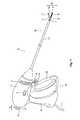
- FIG. 1is a front, perspective view of an endoscopic surgical forceps configured for use in accordance with the present disclosure
- FIG. 2Ais an enlarged, front, perspective view of an end effector assembly of the forceps of FIG. 1 , wherein the jaw members of the end effector assembly are disposed in a spaced-apart position and wherein the monopolar assembly is disposed in a storage position;
- FIG. 2Bis an enlarged, front, perspective view of the end effector assembly of FIG. 2A , wherein the jaw members are disposed in an approximated position and wherein the monopolar assembly is disposed in the storage position;
- FIG. 2Cis an enlarged, front, perspective view of the end effector assembly of FIG. 2A , wherein the jaw members are disposed in the approximated position and wherein the monopolar assembly is transitioning from the storage position to a deployed position;
- FIG. 2Dis an enlarged, front, perspective view of the end effector assembly of FIG. 2A , wherein the monopolar assembly is disposed in the deployed position;
- FIG. 3Ais a longitudinal, cross-sectional view of the end effector assembly of FIG. 2A with the jaw members disposed in the spaced-apart position and wherein the knife is disposed in a retracted position;
- FIG. 3Bis a longitudinal, cross-sectional view of the end effector assembly of FIG. 2A with the jaw members disposed in the approximated position and wherein the knife is disposed in an extended position;
- FIG. 4is an enlarged, longitudinal, cross-sectional view of the proximal end of the forceps of FIG. 1 with portions removed to illustrate the internal components of the selector assembly and the monopolar assembly of the forceps of FIG. 1 ;
- FIG. 5is a perspective view of the selector assembly and the monopolar assembly of the forceps of FIG. 1 ;
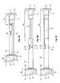
- FIG. 6Ais a perspective view of the selector assembly of FIG. 5 coupled to the monopolar assembly and disposed in an inserted, disengaged position;
- FIG. 6Bis a perspective view of the selector assembly of FIG. 5 coupled to the monopolar assembly and disposed in a withdrawn, disengaged position;
- FIG. 6Cis a perspective view of the selector assembly of FIG. 5 coupled to the monopolar assembly and disposed in a withdrawn, engaged position.
- a forceps provided in accordance with the present disclosureis shown generally identified by reference numeral 10 .
- Forceps 10is configured to operate in both a bipolar mode, e.g., for grasping, treating, and/or dissecting tissue, and a monopolar mode, e.g., for treating and/or dissecting tissue.
- a bipolar modee.g., for grasping, treating, and/or dissecting tissue
- a monopolar modee.g., for treating and/or dissecting tissue.
- forceps 10includes a housing 20 , a handle assembly 30 , a trigger assembly 60 , a rotating assembly 70 , a selector assembly 80 , an end effector assembly 100 , and a deployable monopolar assembly 200 .
- Forceps 10further includes a shaft 12 having a distal end configured to mechanically engage end effector assembly 100 and a proximal end that mechanically engages housing 20 .
- Forceps 10also includes an electrosurgical cable 2 that connects forceps 10 to a generator (not shown) or other suitable power source, although forceps 10 may alternatively be configured as a battery powered instrument.
- Cable 2includes wires (not shown) extending therethrough that have sufficient length to extend through shaft 12 in order to provide electrical energy to at least one electrically-conductive surface 112 , 122 ( FIG. 2A ) of jaw members 110 , 120 , respectively, of end effector assembly 100 , e.g., upon activation of activation switch 4 in a bipolar mode.
- One or more of the wires (not shown) of cable 2extends through housing 20 in order to provide electrical energy to deployable monopolar assembly 200 , e.g., upon activation of activation switch 4 in a monopolar mode.
- Rotating assembly 70is rotatable in either direction to rotate end effector assembly 100 and deployable monopolar assembly 200 relative to housing 20 .
- Housing 20houses the internal working components of forceps 10 , which are described in detail below.
- end effector assembly 100is attached at a distal end of shaft 12 and includes opposing jaw members 110 , 120 pivotably coupled to one another.
- Each of the jaw members 110 and 120includes a jaw body 111 , 121 supporting the respective electrically-conductive surface 112 , 122 , and a respective proximally-extending jaw flange 114 , 124 .
- Flanges 114 , 124are pivotably coupled to one another to permit movement of jaw members 110 , 120 relative to one another between a spaced-apart position ( FIG. 2A ) and an approximated position ( FIG. 2B ) for grasping tissue between surfaces 112 , 122 .
- One or both of surfaces 112 , 122are adapted to connect to a source of energy (not explicitly shown), e.g., via the wires (not shown) of cable 2 ( FIG. 1 ) and are configured to conduct energy through tissue grasped therebetween to treat, e.g., seal, tissue. More specifically, in some embodiments, end effector assembly 100 defines a bipolar configuration wherein surface 112 is charged to a first electrical potential and surface 122 is charged to a second, different electrical potential such that an electrical potential gradient is created for conducting energy between surfaces 112 , 122 and through tissue grasped therebetween for treating e.g., sealing, tissue.
- Activation switch 4FIG.
- End effector assembly 100is designed as a unilateral assembly, i.e., where jaw member 120 is fixed relative to shaft 12 and jaw member 110 is movable relative to shaft 12 and fixed jaw member 120 .
- end effector assembly 100may alternatively be configured as a bilateral assembly, i.e., where both jaw member 110 and jaw member 120 are movable relative to one another and to shaft 12 .
- a knife channel 115 , 125may be defined within one or both of jaw members 110 , 120 to permit reciprocation of a knife 184 ( FIGS. 3A and 3B ) therethrough, e.g., upon actuation of a trigger 62 of trigger assembly 60 , to cut tissue grasped between jaw members 110 , 120 .
- deployable monopolar assembly 200includes an insulative sleeve 210 , an energizable rod member 220 , a proximal hub assembly 230 ( FIGS. 4 and 5 ), and a biasing member (not shown).
- Insulative sleeve 210is slidably disposed about shaft 12 and is selectively movable about and relative to shaft 12 and end effector assembly 100 between a storage position ( FIG. 2B ), wherein insulative sleeve 210 is disposed proximally of end effector assembly 100 , and a deployed position ( FIG.
- insulative sleeve 210is substantially disposed about end effector assembly 100 so as to electrically insulate surfaces 112 , 122 of jaw members 110 , 120 , respectively, from the surroundings of insulative sleeve 210 .
- Energizable rod member 220extends through sleeve 210 and distally therefrom, ultimately defining an electrically-conductive distal tip 224 .
- the one or more wires(not shown) extending from cable 2 through housing 20 (see FIG. 1 ), are coupled to energizable rod member 220 to provide energy to energizable rod member 220 , e.g., upon actuation of activation switch 4 ( FIG. 1 ) in a monopolar mode, for treating tissue in a monopolar mode of operation.
- Energizable rod member 220is movable between a storage position ( FIG.
- distal tip 224 of energizable rod member 220is positioned adjacent proximal flange 124 of jaw member 120 , and a deployed position ( FIG. 2D ), wherein distal tip 224 of rod member 220 extends distally from the distal ends of jaw members 110 , 120 .
- distal tip 224 of energizable rod member 220 of deployable monopolar assembly 200is disposed within insulated groove 126 defined within proximal flange 124 of jaw member 120 , although other configurations are also contemplated.
- Insulated groove 126electrically-insulates distal tip 224 of energizable rod member 220 from electrically-conductive surfaces 112 , 122 of jaw members 110 , 120 , respectively, and from surrounding tissue when disposed in the storage position.
- distal tip 224 of energizable rod member 220may only be insulated from surface 112 (or surface 122 ). In such configurations, distal tip 224 of energizable rod member 220 is capable of being energized to the same polarity as surface 122 (or surface 112 ). In the deployed position of energizable rod member 220 , as shown in FIG.
- distal tip 224 of energizable rod member 220extends distally from end effector assembly 100 and insulative sleeve 210 , which substantially surrounds end effector assembly 100 in the deployed position. In this position, energy may be applied to distal tip 224 of energizable rod member 220 to treat tissue, e.g., via activation of activation switch 4 ( FIG. 1 ) in the monopolar mode.
- Distal tip 224may be hook-shaped (as shown), or may define any other suitable configuration, e.g., linear, circular, angled, etc.
- proximal hub assembly 230includes an outer collar 232 , an inner base 234 , and an elongated member 236 .
- Outer collar 232is coupled to insulative sleeve 210 at the proximal end of insulative sleeve 210 .
- Inner base 234is coupled to energizable rod member 220 at the proximal end of energizable rod member 220 .
- both insulative sleeve 210 and energizable rod member 220are coupled to proximal hub assembly 230 such that insulative sleeve 210 and energizable rod member 220 are capable of being moved together between their respective storage positions ( FIG. 2B ), e.g., the storage condition of deployable monopolar assembly 200 , and their respective deployed positions ( FIG. 2D ), e.g., the deployed condition of deployable monopolar assembly 200 , upon selective translation of proximal hub assembly 230 through housing 20 , as will be detailed below.
- Elongated member 236 of proximal hub assembly 230is coupled to and extends proximally from inner base member 234 .
- Elongated member 236defines a generally cylindrical-shaped configuration, although other configurations are also contemplated, and includes a pair of opposed engagement cut-outs 238 defined therein towards the proximal end thereof, the importance of which is detailed below.
- the biasing member (not shown) of deployable monopolar assembly 200may be positioned about insulative sleeve 210 distally of outer collar 232 of proximal hub assembly 230 , within insulative sleeve distally of inner base 234 of proximal hub assembly 230 , or in any other suitable position so as to bias proximal hub assembly 230 and, thus, insulative sleeve 210 and energizable rod member 220 proximally towards the respective storage positions thereof, although other suitable biasing members and/or biasing configurations are also contemplated.
- handle assembly 30includes a movable handle 40 and a fixed handle 50 .
- Fixed handle 50is integrally associated with housing 20 and movable handle 40 is movable relative to fixed handle 50 .
- Movable handle 40is movable relative to fixed handle 50 between an initial position, wherein movable handle 40 is spaced from fixed handle 50 , and a compressed position, wherein movable handle 40 is compressed towards fixed handle 50 .
- a biasing member(not shown) may be provided to bias movable handle 40 towards the initial position.
- Movable handle 40is ultimately connected to a drive assembly 140 (portions removed from FIG. 4 ) that, together, mechanically cooperate to impart movement of jaw members 110 , 120 between the spaced-apart position ( FIG. 2A ), corresponding to the initial position of movable handle 40 , and the approximated position ( FIG. 2B ), corresponding to the compressed position of movable handle 40 .
- Any suitable drive assembly 140 for this purposemay be provided.
- trigger assembly 60includes trigger 62 that is operably coupled to a knife assembly 180 (portions removed from FIG. 4 ).
- Knife assembly 180includes a knife drive bar 182 having a knife 184 extending from the distal end thereof.
- a knife biasing member(not shown) may be disposed about knife drive bar 182 to bias knife assembly 180 proximally.
- Trigger 62 of trigger assembly 60is selectively actuatable from an un-actuated position to an actuated position to advance knife 184 from a retracted position ( FIG. 3A ), wherein knife 184 is disposed proximally of jaw members 110 , 120 , to an extended position ( FIG. 3B ), wherein knife 184 extends at least partially between jaw members 110 , 120 and through knife channels 115 , 125 , respectively, to cut tissue grasped between jaw members 110 , 120 .
- selector assembly 80is translatable relative to housing 20 between an inserted position ( FIGS. 1 and 6A ), wherein selector assembly 80 is substantially disposed within housing 20 , and a withdrawn position ( FIGS. 6B and 6C ), wherein selector assembly 80 extends further proximally from housing 20 .
- selector assembly 80is transitionable between first orientation corresponding to a first state of selector assembly 80 (see FIG.
- selector assembly 80is disengaged from deployable monopolar assembly 200 , e.g., such that deployable monopolar assembly 200 remains disposed in the storage condition regardless of the translation of selector assembly 80 , and a second orientation corresponding to a second state of selector assembly 80 (see FIG. 6C ), wherein selector assembly 80 is engaged with deployable monopolar assembly 200 such that selector assembly 80 may be translated between the withdrawn position and the inserted position for selectively transitioning deployable monopolar assembly 200 between the storage condition and the deployed condition, respectively.
- Selector assembly 80is rotatable and translatable relative to housing 20 , and includes a plunger 82 and a pair of spaced-apart arms 85 extending distally from plunger 82 .
- Plunger 82extends proximally through an aperture defined within housing 20 and includes a body portion 83 and a manipulation knob 84 that facilitates manual manipulation of plunger 82 from the exterior of housing 20 .
- Arms 85extend distally from plunger 82 through housing 20 and are positioned on opposed sides of elongated member 236 of deployable monopolar assembly 200 .
- Each arm 85includes a free end having an inwardly-extending tab 86 disposed thereon. In the inserted position of selector assembly 80 ( FIGS.
- tabs 86 of arms 85are positioned adjacent the distal end of elongated member 236 .
- tabs 86 of arms 85are positioned adjacent cut-outs 238 defined within elongated member 236 . More specifically, with selector assembly 80 disposed in the withdrawn position and the first orientation ( FIG. 6B ), tabs 86 of arms 85 are rotationally offset from respective cut-outs 238 of elongated member 236 such that selector assembly 80 remains disengaged from deployable monopolar assembly 200 .
- selector assembly 80is rotated to the second orientation ( FIG.
- tabs 86 of arms 85are positioned adjacent respective cut-outs 238 of elongated member 236 .
- the free ends of arms 85may be resiliently biased towards a generally linear configuration, may be resiliently biased inwardly towards one another, or may be otherwise configured such that, with selector assembly 80 disposed in the withdrawn position and the second orientation, tabs 86 of arms 85 are engaged within cut-outs 238 of elongated member 238 to thereby operably engage selector assembly 80 with deployable monopolar assembly 200 .
- this engaged conditiontranslation of selector assembly 80 , e.g., via manual translation of plunger 82 relative to housing 20 , may be effected to transition deployable monopolar assembly 200 between the storage condition ( FIG. 2A ) and the deployed condition ( FIG. 2D ).
- forceps 10in both the bipolar mode, e.g., for grasping, treating and/or cutting tissue, and the monopolar mode, e.g., for electrical/electromechanical tissue treatment, is described.
- deployable monopolar assembly 200is disposed in the storage condition ( FIG. 2A ) and selector assembly 80 is disposed in the inserted position and the first orientation ( FIG. 6A ).
- Jaw members 110 , 120are initially disposed in the spaced-apart position and trigger assembly 60 is disposed in the un-actuated position such that knife 184 is disposed in the retracted position ( FIG. 3A ).
- end effector assembly 100may be maneuvered into position such that tissue to be grasped, treated, e.g., sealed, and/or cut, is disposed between jaw members 110 , 120 .
- movable handle 40is depressed, or pulled proximally relative to fixed handle 50 such that jaw member 110 is pivoted relative to jaw member 120 from the spaced-apart position to the approximated position to grasp tissue therebetween ( FIG. 2B ).
- energymay be supplied, e.g., via activation of switch 4 , to surface 112 of jaw member 110 and/or surface 122 of jaw member 120 and conducted through tissue to treat tissue, e.g., to effect a tissue seal or otherwise treat tissue in the bipolar mode of operation.
- knife 184 of knife assembly 180may be deployed from within shaft 12 to between jaw members 110 , 120 , e.g., via actuation of trigger 62 of trigger assembly 60 (see FIG. 1 ), to cut tissue grasped therebetween (see FIGS. 3A and 3B ).
- trigger 62may be released to allow knife 184 to return under bias to the retracted position.
- jaw members 110 , 120may be moved back to the spaced-apart position ( FIG. 2A ) to release the treated and/or divided tissue.
- selector assembly 80is disposed in the inserted position and the first orientation ( FIG. 6A ).
- selector assembly 80is initially translated proximally from the inserted position ( FIG. 6A ) to the withdrawn position ( FIG. 6B ), e.g., via grasping and manually translating manipulation knob 84 of plunger 82 proximally relative to housing 20 .
- selector assembly 80is rotated from the first orientation ( FIG. 6B ) to the second orientation ( FIG.
- selector assembly 80may thereafter be translated distally, e.g., further into housing 20 , to transition deployable monopolar assembly 200 from the storage condition ( FIG. 2A ) to the deployed condition ( FIG. 2D ).
- activation switch 4may be actuated to supply energy to energizable rod member 220 of deployable monopolar assembly 200 to treat tissue with monopolar energy.
- manipulation knob 84 of selector assembly 80may be translated proximally, e.g., withdrawn from housing 20 , such that deployable monopolar assembly 200 is transitioned from the deployed condition ( FIG. 2D ) back to the storage condition ( FIG. 2A ).
- selector assembly 80may be rotated back to the first orientation ( FIG. 6B ) to disengage deployable monopolar assembly 200 from selector assembly 80 and, ultimately, back to the inserted position ( FIG. 6A ) to retain deployable monopolar assembly 200 in the storage condition ( FIG. 2A ).
Landscapes
- Health & Medical Sciences (AREA)
- Surgery (AREA)
- Engineering & Computer Science (AREA)
- Life Sciences & Earth Sciences (AREA)
- Biomedical Technology (AREA)
- Otolaryngology (AREA)
- Nuclear Medicine, Radiotherapy & Molecular Imaging (AREA)
- Plasma & Fusion (AREA)
- Physics & Mathematics (AREA)
- Heart & Thoracic Surgery (AREA)
- Medical Informatics (AREA)
- Molecular Biology (AREA)
- Animal Behavior & Ethology (AREA)
- General Health & Medical Sciences (AREA)
- Public Health (AREA)
- Veterinary Medicine (AREA)
- Surgical Instruments (AREA)
Abstract
Description
Claims (13)
Priority Applications (2)
| Application Number | Priority Date | Filing Date | Title |
|---|---|---|---|
| US14/543,200US9814516B2 (en) | 2014-11-17 | 2014-11-17 | Deployment mechanisms for multi-function surgical instruments |
| EP15191292.0AEP3020353B1 (en) | 2014-11-17 | 2015-10-23 | Deployment mechanisms for multi-function surgical instruments |
Applications Claiming Priority (1)
| Application Number | Priority Date | Filing Date | Title |
|---|---|---|---|
| US14/543,200US9814516B2 (en) | 2014-11-17 | 2014-11-17 | Deployment mechanisms for multi-function surgical instruments |
Publications (2)
| Publication Number | Publication Date |
|---|---|
| US20160135866A1 US20160135866A1 (en) | 2016-05-19 |
| US9814516B2true US9814516B2 (en) | 2017-11-14 |
Family
ID=54360175
Family Applications (1)
| Application Number | Title | Priority Date | Filing Date |
|---|---|---|---|
| US14/543,200Active2036-01-22US9814516B2 (en) | 2014-11-17 | 2014-11-17 | Deployment mechanisms for multi-function surgical instruments |
Country Status (2)
| Country | Link |
|---|---|
| US (1) | US9814516B2 (en) |
| EP (1) | EP3020353B1 (en) |
Cited By (2)
| Publication number | Priority date | Publication date | Assignee | Title |
|---|---|---|---|---|
| USD844138S1 (en)* | 2015-07-17 | 2019-03-26 | Covidien Lp | Handle assembly of a multi-function surgical instrument |
| USD844139S1 (en)* | 2015-07-17 | 2019-03-26 | Covidien Lp | Monopolar assembly of a multi-function surgical instrument |
Citations (56)
| Publication number | Priority date | Publication date | Assignee | Title |
|---|---|---|---|---|
| US5312391A (en) | 1992-07-29 | 1994-05-17 | Wilk Peter J | Laparoscopic instrument assembly |
| US5318589A (en) | 1992-04-15 | 1994-06-07 | Microsurge, Inc. | Surgical instrument for endoscopic surgery |
| US5324254A (en) | 1990-05-25 | 1994-06-28 | Phillips Edward H | Tool for laparoscopic surgery |
| US5401274A (en) | 1992-04-20 | 1995-03-28 | Olympus Optical Co., Ltd. | High-frequency treating instrument |
| US5445638A (en) | 1993-03-08 | 1995-08-29 | Everest Medical Corporation | Bipolar coagulation and cutting forceps |
| US5458598A (en) | 1993-12-02 | 1995-10-17 | Cabot Technology Corporation | Cutting and coagulating forceps |
| US5556397A (en) | 1994-10-26 | 1996-09-17 | Laser Centers Of America | Coaxial electrosurgical instrument |
| US5735873A (en) | 1996-12-19 | 1998-04-07 | Maclean; David S. | Surgical tool handle |
| US5792164A (en) | 1994-12-19 | 1998-08-11 | Lakatos; Nick | Surgical instrument |
| US5893863A (en) | 1989-12-05 | 1999-04-13 | Yoon; Inbae | Surgical instrument with jaws and movable internal hook member for use thereof |
| US5919202A (en) | 1989-12-05 | 1999-07-06 | Yoon; Inbae | Surgical instrument with jaws and movable internal needle and method for use thereof |
| US6113596A (en) | 1996-12-30 | 2000-09-05 | Enable Medical Corporation | Combination monopolar-bipolar electrosurgical instrument system, instrument and cable |
| US6156009A (en) | 1996-12-05 | 2000-12-05 | Comedicus Incorporated | Apparatus for accessing the pericardial space |
| US6190386B1 (en) | 1999-03-09 | 2001-02-20 | Everest Medical Corporation | Electrosurgical forceps with needle electrodes |
| US6270497B1 (en) | 1998-08-27 | 2001-08-07 | Olympus Optical Co., Ltd. | High-frequency treatment apparatus having control mechanism for incising tissue after completion of coagulation by high-frequency treatment tool |
| US6299625B1 (en) | 1998-08-12 | 2001-10-09 | Karl Storz Gmbh & Co. Kg | Handle for a medical instrument |
| US20020049442A1 (en) | 1999-07-27 | 2002-04-25 | Roberts Troy W. | Biopsy sampler |
| US6387094B1 (en) | 1998-10-30 | 2002-05-14 | Karl Storz Gmbh & Co. Kg | Medical instrument for dissecting tissue |
| US6551313B1 (en) | 2001-05-02 | 2003-04-22 | John M. Levin | Electrosurgical instrument with separate cutting and coagulating members |
| US6679882B1 (en) | 1998-06-22 | 2004-01-20 | Lina Medical Aps | Electrosurgical device for coagulating and for making incisions, a method of severing blood vessels and a method of coagulating and for making incisions in or severing tissue |
| US6699206B2 (en) | 1998-03-03 | 2004-03-02 | Senorx, Inc. | Breast biopsy system and methods |
| US20040116920A1 (en) | 2002-12-11 | 2004-06-17 | Scimed Life Systems, Inc. | Angle indexer for medical devices |
| US6808525B2 (en) | 2001-08-27 | 2004-10-26 | Gyrus Medical, Inc. | Bipolar electrosurgical hook probe for cutting and coagulating tissue |
| US20040236326A1 (en) | 2001-01-24 | 2004-11-25 | Schulze Dale R. | Electrosurgical instrument with closing tube for conducting RF energy and moving jaws |
| US20050187547A1 (en) | 2004-02-25 | 2005-08-25 | Yoshihiko Sugi | High frequency treatment device having a pair of jaws with electrodes |
| US6942662B2 (en) | 2001-12-27 | 2005-09-13 | Gyrus Group Plc | Surgical Instrument |
| US7033356B2 (en) | 2002-07-02 | 2006-04-25 | Gyrus Medical, Inc. | Bipolar electrosurgical instrument for cutting desiccating and sealing tissue |
| US7063699B2 (en) | 2001-01-24 | 2006-06-20 | Ethicon, Inc. | Electrosurgical instrument with minimally invasive jaws |
| US7128254B2 (en) | 2004-09-07 | 2006-10-31 | Ethicon Endo-Surgery, Inc. | Surgical stapling instrument incorporating a multistroke firing mechanism having a rotary slip-clutch transmission |
| US7232440B2 (en) | 2003-11-17 | 2007-06-19 | Sherwood Services Ag | Bipolar forceps having monopolar extension |
| US7367976B2 (en) | 2003-11-17 | 2008-05-06 | Sherwood Services Ag | Bipolar forceps having monopolar extension |
| US7402162B2 (en) | 2004-03-24 | 2008-07-22 | Hoya Corporation | High frequency treatment instrument for endoscope |
| US20080215050A1 (en) | 2007-03-02 | 2008-09-04 | Ethicon Endo-Surgery, Inc. | Tissue engaging hemostasis device |
| US7510562B2 (en) | 2003-07-08 | 2009-03-31 | Terumo Corporation | Vein dissector, cauterizing and ligating apparatus for endoscopic harvesting of blood vessels |
| US20090125027A1 (en) | 2006-04-11 | 2009-05-14 | Klaus Fischer | Multifunction device for endoscopic surgery |
| US20090125026A1 (en) | 2007-11-13 | 2009-05-14 | Boston Scientific Scimed, Inc. | Apparatus system and method for coagulating and cutting tissue |
| US20090131974A1 (en) | 2004-12-29 | 2009-05-21 | Surgitech Norway As | Instrument, particularly for use in laparoscopic surgery |
| US7588570B2 (en) | 2003-06-09 | 2009-09-15 | Tohru Tani | Medical treatment instrument and medical treatment apparatus including the same |
| US20090254084A1 (en) | 2008-04-08 | 2009-10-08 | Naito Kimihiko | High-frequency treatment apparatus |
| US7658311B2 (en) | 2007-06-22 | 2010-02-09 | Ethicon Endo-Surgery, Inc. | Surgical stapling instrument with a geared return mechanism |
| US7758577B2 (en) | 2006-12-05 | 2010-07-20 | Ethicon Endo-Surgery, Inc. | Monopolar resection device and method of use |
| US20100185197A1 (en) | 2009-01-21 | 2010-07-22 | Satomi Sakao | Medical treatment apparatus, treatment instrument and treatment method for living tissue using energy |
| US20100185196A1 (en) | 2009-01-21 | 2010-07-22 | Satomi Sakao | Medical treatment apparatus, treatment instrument and treatment method for living tissue using energy |
| US7815636B2 (en) | 2005-11-29 | 2010-10-19 | Ethicon Endo-Surgery, Inc. | Auto-safety shut-off for energy based devices |
| US7819872B2 (en) | 2005-09-30 | 2010-10-26 | Covidien Ag | Flexible endoscopic catheter with ligasure |
| US20100292690A1 (en) | 2009-03-02 | 2010-11-18 | Bovie Medical Corporation | Surgical apparatus for tissue sealing and cutting |
| US20110087173A1 (en) | 2009-10-12 | 2011-04-14 | Sibbitt Jr Wilmer L | Automatic syringes |
| US20110087218A1 (en) | 2009-10-09 | 2011-04-14 | Ethicon Endo-Surgery, Inc. | Surgical instrument comprising first and second drive systems actuatable by a common trigger mechanism |
| US20110130757A1 (en) | 2008-06-30 | 2011-06-02 | Celon Ag Medical Instruments | Electrosurgical instrument |
| US20110264093A1 (en) | 2010-04-22 | 2011-10-27 | Ethicon Endo-Surgery, Inc. | Electrosurgical instrument comprising closing and firing systems |
| US20120116396A1 (en)* | 2010-11-05 | 2012-05-10 | Price Daniel W | Surgical instrument with modular end effector |
| US20120330351A1 (en) | 2009-09-30 | 2012-12-27 | Aegis Medical Innovations Inc. | Tissue capture and occlusion systems and methods |
| US8353437B2 (en) | 2007-06-22 | 2013-01-15 | Ethicon Endo-Surgery, Inc. | Surgical stapling instrument with a geared return mechanism |
| EP2679185A1 (en) | 2012-06-29 | 2014-01-01 | Covidien LP | Surgical forceps |
| US20140046327A1 (en) | 2011-04-11 | 2014-02-13 | Waismed Ltd. | Intraosseous Device For Inserting A Cannula Into A Bone |
| US20140276797A1 (en) | 2013-03-15 | 2014-09-18 | GYRUS ACMI, INC., d/b/a Olympus Surgical Technologies America | Combination electrosurgical device |
- 2014
- 2014-11-17USUS14/543,200patent/US9814516B2/enactiveActive
- 2015
- 2015-10-23EPEP15191292.0Apatent/EP3020353B1/enactiveActive
Patent Citations (59)
| Publication number | Priority date | Publication date | Assignee | Title |
|---|---|---|---|---|
| US5893863A (en) | 1989-12-05 | 1999-04-13 | Yoon; Inbae | Surgical instrument with jaws and movable internal hook member for use thereof |
| US5919202A (en) | 1989-12-05 | 1999-07-06 | Yoon; Inbae | Surgical instrument with jaws and movable internal needle and method for use thereof |
| US5324254A (en) | 1990-05-25 | 1994-06-28 | Phillips Edward H | Tool for laparoscopic surgery |
| US5318589A (en) | 1992-04-15 | 1994-06-07 | Microsurge, Inc. | Surgical instrument for endoscopic surgery |
| US5401274A (en) | 1992-04-20 | 1995-03-28 | Olympus Optical Co., Ltd. | High-frequency treating instrument |
| US5312391A (en) | 1992-07-29 | 1994-05-17 | Wilk Peter J | Laparoscopic instrument assembly |
| US5445638A (en) | 1993-03-08 | 1995-08-29 | Everest Medical Corporation | Bipolar coagulation and cutting forceps |
| US5445638B1 (en) | 1993-03-08 | 1998-05-05 | Everest Medical Corp | Bipolar coagulation and cutting forceps |
| US5458598A (en) | 1993-12-02 | 1995-10-17 | Cabot Technology Corporation | Cutting and coagulating forceps |
| US5556397A (en) | 1994-10-26 | 1996-09-17 | Laser Centers Of America | Coaxial electrosurgical instrument |
| US5792164A (en) | 1994-12-19 | 1998-08-11 | Lakatos; Nick | Surgical instrument |
| US6156009A (en) | 1996-12-05 | 2000-12-05 | Comedicus Incorporated | Apparatus for accessing the pericardial space |
| US5735873A (en) | 1996-12-19 | 1998-04-07 | Maclean; David S. | Surgical tool handle |
| US6113596A (en) | 1996-12-30 | 2000-09-05 | Enable Medical Corporation | Combination monopolar-bipolar electrosurgical instrument system, instrument and cable |
| US6699206B2 (en) | 1998-03-03 | 2004-03-02 | Senorx, Inc. | Breast biopsy system and methods |
| US6679882B1 (en) | 1998-06-22 | 2004-01-20 | Lina Medical Aps | Electrosurgical device for coagulating and for making incisions, a method of severing blood vessels and a method of coagulating and for making incisions in or severing tissue |
| US6299625B1 (en) | 1998-08-12 | 2001-10-09 | Karl Storz Gmbh & Co. Kg | Handle for a medical instrument |
| US6270497B1 (en) | 1998-08-27 | 2001-08-07 | Olympus Optical Co., Ltd. | High-frequency treatment apparatus having control mechanism for incising tissue after completion of coagulation by high-frequency treatment tool |
| US6387094B1 (en) | 1998-10-30 | 2002-05-14 | Karl Storz Gmbh & Co. Kg | Medical instrument for dissecting tissue |
| US6190386B1 (en) | 1999-03-09 | 2001-02-20 | Everest Medical Corporation | Electrosurgical forceps with needle electrodes |
| US20020049442A1 (en) | 1999-07-27 | 2002-04-25 | Roberts Troy W. | Biopsy sampler |
| US7063699B2 (en) | 2001-01-24 | 2006-06-20 | Ethicon, Inc. | Electrosurgical instrument with minimally invasive jaws |
| US20040236326A1 (en) | 2001-01-24 | 2004-11-25 | Schulze Dale R. | Electrosurgical instrument with closing tube for conducting RF energy and moving jaws |
| US6551313B1 (en) | 2001-05-02 | 2003-04-22 | John M. Levin | Electrosurgical instrument with separate cutting and coagulating members |
| US6808525B2 (en) | 2001-08-27 | 2004-10-26 | Gyrus Medical, Inc. | Bipolar electrosurgical hook probe for cutting and coagulating tissue |
| US6942662B2 (en) | 2001-12-27 | 2005-09-13 | Gyrus Group Plc | Surgical Instrument |
| US7033356B2 (en) | 2002-07-02 | 2006-04-25 | Gyrus Medical, Inc. | Bipolar electrosurgical instrument for cutting desiccating and sealing tissue |
| US20040116920A1 (en) | 2002-12-11 | 2004-06-17 | Scimed Life Systems, Inc. | Angle indexer for medical devices |
| US7588570B2 (en) | 2003-06-09 | 2009-09-15 | Tohru Tani | Medical treatment instrument and medical treatment apparatus including the same |
| US7510562B2 (en) | 2003-07-08 | 2009-03-31 | Terumo Corporation | Vein dissector, cauterizing and ligating apparatus for endoscopic harvesting of blood vessels |
| US8257352B2 (en) | 2003-11-17 | 2012-09-04 | Covidien Ag | Bipolar forceps having monopolar extension |
| US7367976B2 (en) | 2003-11-17 | 2008-05-06 | Sherwood Services Ag | Bipolar forceps having monopolar extension |
| US7445621B2 (en) | 2003-11-17 | 2008-11-04 | Covidien Ag | Bipolar forceps having monopolar extension |
| US7232440B2 (en) | 2003-11-17 | 2007-06-19 | Sherwood Services Ag | Bipolar forceps having monopolar extension |
| US20050187547A1 (en) | 2004-02-25 | 2005-08-25 | Yoshihiko Sugi | High frequency treatment device having a pair of jaws with electrodes |
| US7402162B2 (en) | 2004-03-24 | 2008-07-22 | Hoya Corporation | High frequency treatment instrument for endoscope |
| US7128254B2 (en) | 2004-09-07 | 2006-10-31 | Ethicon Endo-Surgery, Inc. | Surgical stapling instrument incorporating a multistroke firing mechanism having a rotary slip-clutch transmission |
| US20090131974A1 (en) | 2004-12-29 | 2009-05-21 | Surgitech Norway As | Instrument, particularly for use in laparoscopic surgery |
| US7819872B2 (en) | 2005-09-30 | 2010-10-26 | Covidien Ag | Flexible endoscopic catheter with ligasure |
| US7815636B2 (en) | 2005-11-29 | 2010-10-19 | Ethicon Endo-Surgery, Inc. | Auto-safety shut-off for energy based devices |
| US20090125027A1 (en) | 2006-04-11 | 2009-05-14 | Klaus Fischer | Multifunction device for endoscopic surgery |
| US7758577B2 (en) | 2006-12-05 | 2010-07-20 | Ethicon Endo-Surgery, Inc. | Monopolar resection device and method of use |
| US20080215050A1 (en) | 2007-03-02 | 2008-09-04 | Ethicon Endo-Surgery, Inc. | Tissue engaging hemostasis device |
| US7658311B2 (en) | 2007-06-22 | 2010-02-09 | Ethicon Endo-Surgery, Inc. | Surgical stapling instrument with a geared return mechanism |
| US8353437B2 (en) | 2007-06-22 | 2013-01-15 | Ethicon Endo-Surgery, Inc. | Surgical stapling instrument with a geared return mechanism |
| US20090125026A1 (en) | 2007-11-13 | 2009-05-14 | Boston Scientific Scimed, Inc. | Apparatus system and method for coagulating and cutting tissue |
| US20090254084A1 (en) | 2008-04-08 | 2009-10-08 | Naito Kimihiko | High-frequency treatment apparatus |
| US20110130757A1 (en) | 2008-06-30 | 2011-06-02 | Celon Ag Medical Instruments | Electrosurgical instrument |
| US20100185197A1 (en) | 2009-01-21 | 2010-07-22 | Satomi Sakao | Medical treatment apparatus, treatment instrument and treatment method for living tissue using energy |
| US20100185196A1 (en) | 2009-01-21 | 2010-07-22 | Satomi Sakao | Medical treatment apparatus, treatment instrument and treatment method for living tissue using energy |
| US20100292690A1 (en) | 2009-03-02 | 2010-11-18 | Bovie Medical Corporation | Surgical apparatus for tissue sealing and cutting |
| US20120330351A1 (en) | 2009-09-30 | 2012-12-27 | Aegis Medical Innovations Inc. | Tissue capture and occlusion systems and methods |
| US20110087218A1 (en) | 2009-10-09 | 2011-04-14 | Ethicon Endo-Surgery, Inc. | Surgical instrument comprising first and second drive systems actuatable by a common trigger mechanism |
| US20110087173A1 (en) | 2009-10-12 | 2011-04-14 | Sibbitt Jr Wilmer L | Automatic syringes |
| US20110264093A1 (en) | 2010-04-22 | 2011-10-27 | Ethicon Endo-Surgery, Inc. | Electrosurgical instrument comprising closing and firing systems |
| US20120116396A1 (en)* | 2010-11-05 | 2012-05-10 | Price Daniel W | Surgical instrument with modular end effector |
| US20140046327A1 (en) | 2011-04-11 | 2014-02-13 | Waismed Ltd. | Intraosseous Device For Inserting A Cannula Into A Bone |
| EP2679185A1 (en) | 2012-06-29 | 2014-01-01 | Covidien LP | Surgical forceps |
| US20140276797A1 (en) | 2013-03-15 | 2014-09-18 | GYRUS ACMI, INC., d/b/a Olympus Surgical Technologies America | Combination electrosurgical device |
Non-Patent Citations (1)
| Title |
|---|
| European Search Report issued in corresponding application No. EP 15191292.0 on Jan. 19, 2016. |
Cited By (2)
| Publication number | Priority date | Publication date | Assignee | Title |
|---|---|---|---|---|
| USD844138S1 (en)* | 2015-07-17 | 2019-03-26 | Covidien Lp | Handle assembly of a multi-function surgical instrument |
| USD844139S1 (en)* | 2015-07-17 | 2019-03-26 | Covidien Lp | Monopolar assembly of a multi-function surgical instrument |
Also Published As
| Publication number | Publication date |
|---|---|
| EP3020353A1 (en) | 2016-05-18 |
| EP3020353B1 (en) | 2018-02-28 |
| US20160135866A1 (en) | 2016-05-19 |
Similar Documents
| Publication | Publication Date | Title |
|---|---|---|
| US11864822B2 (en) | Deployment mechanisms for surgical instruments | |
| US20210161585A1 (en) | Multi-function surgical instruments | |
| US9918784B2 (en) | Surgical forceps | |
| US9987076B2 (en) | Multi-function surgical instruments | |
| US12048473B2 (en) | Deployment mechanism for surgical instruments | |
| US20170303995A1 (en) | Switch assemblies for multi-function surgical instruments and surgical instruments incorporating the same | |
| US10631920B2 (en) | Deployment mechanism for surgical instruments | |
| US9814517B2 (en) | Deployment mechanisms for multi-function surgical instruments | |
| US9814516B2 (en) | Deployment mechanisms for multi-function surgical instruments |
Legal Events
| Date | Code | Title | Description |
|---|---|---|---|
| AS | Assignment | Owner name:COVIDIEN ENGINEERING SERVICES PRIVATE LIMITED, IND Free format text:ASSIGNMENT OF ASSIGNORS INTEREST;ASSIGNOR:JADHAV, AMARSINH D.;REEL/FRAME:034195/0452 Effective date:20141030 Owner name:COVIDIEN ENGINEERING SERVICES PRIVATE LIMITED, IND Free format text:ASSIGNMENT OF ASSIGNORS INTEREST;ASSIGNOR:KULKARNI, ABHIJIT G.;REEL/FRAME:034195/0743 Effective date:20141030 Owner name:COVIDIEN ENGINEERING SERVICES PRIVATE LIMITED, IND Free format text:ASSIGNMENT OF ASSIGNORS INTEREST;ASSIGNOR:CHELLADURAI, THIYAGARAJAN;REEL/FRAME:034196/0964 Effective date:20141030 | |
| AS | Assignment | Owner name:COVIDIEN AG, SWITZERLAND Free format text:ASSIGNMENT OF ASSIGNORS INTEREST;ASSIGNOR:COVIDIEN PRIVATE LIMITED;REEL/FRAME:035498/0819 Effective date:20150324 Owner name:COVIDIEN LP, MASSACHUSETTS Free format text:ASSIGNMENT OF ASSIGNORS INTEREST;ASSIGNOR:COVIDIEN AG;REEL/FRAME:035498/0889 Effective date:20150408 Owner name:COVIDIEN PRIVATE LIMITED, SINGAPORE Free format text:ASSIGNMENT OF ASSIGNORS INTEREST;ASSIGNOR:COVIDIEN ENGINEERING SERVICES PRIVATE LIMITED;REEL/FRAME:035498/0729 Effective date:20150317 | |
| STCF | Information on status: patent grant | Free format text:PATENTED CASE | |
| MAFP | Maintenance fee payment | Free format text:PAYMENT OF MAINTENANCE FEE, 4TH YEAR, LARGE ENTITY (ORIGINAL EVENT CODE: M1551); ENTITY STATUS OF PATENT OWNER: LARGE ENTITY Year of fee payment:4 | |
| MAFP | Maintenance fee payment | Free format text:PAYMENT OF MAINTENANCE FEE, 8TH YEAR, LARGE ENTITY (ORIGINAL EVENT CODE: M1552); ENTITY STATUS OF PATENT OWNER: LARGE ENTITY Year of fee payment:8 |