US9814511B2 - Variable geometry cooling chamber - Google Patents
Variable geometry cooling chamberDownload PDFInfo
- Publication number
- US9814511B2 US9814511B2US11/476,928US47692806AUS9814511B2US 9814511 B2US9814511 B2US 9814511B2US 47692806 AUS47692806 AUS 47692806AUS 9814511 B2US9814511 B2US 9814511B2
- Authority
- US
- United States
- Prior art keywords
- shaping element
- medical device
- geometric configuration
- shaping
- geometric
- Prior art date
- Legal status (The legal status is an assumption and is not a legal conclusion. Google has not performed a legal analysis and makes no representation as to the accuracy of the status listed.)
- Expired - Fee Related, expires
Links
- 238000001816coolingMethods0.000titledescription2
- 238000007493shaping processMethods0.000claimsabstractdescription62
- 239000012781shape memory materialSubstances0.000claimsdescription6
- 230000007704transitionEffects0.000claimsdescription4
- 229910001092metal group alloyInorganic materials0.000claims1
- 239000012530fluidSubstances0.000abstractdescription25
- 238000002347injectionMethods0.000abstractdescription9
- 239000007924injectionSubstances0.000abstractdescription9
- 238000004891communicationMethods0.000abstractdescription8
- 230000003902lesionEffects0.000description14
- 238000000034methodMethods0.000description7
- 239000002826coolantSubstances0.000description6
- 239000000463materialSubstances0.000description6
- 238000002679ablationMethods0.000description3
- 239000013013elastic materialSubstances0.000description3
- 238000010276constructionMethods0.000description2
- 230000007246mechanismEffects0.000description2
- 230000006793arrhythmiaEffects0.000description1
- 206010003119arrhythmiaDiseases0.000description1
- 230000008859changeEffects0.000description1
- 230000008878couplingEffects0.000description1
- 238000010168coupling processMethods0.000description1
- 238000005859coupling reactionMethods0.000description1
- 238000001514detection methodMethods0.000description1
- 238000011161developmentMethods0.000description1
- 230000010339dilationEffects0.000description1
- 230000000694effectsEffects0.000description1
- 239000004744fabricSubstances0.000description1
- 238000009413insulationMethods0.000description1
- 238000012986modificationMethods0.000description1
- 230000004048modificationEffects0.000description1
- 229910001000nickel titaniumInorganic materials0.000description1
- 238000011160researchMethods0.000description1
- 238000001356surgical procedureMethods0.000description1
- 238000007669thermal treatmentMethods0.000description1
Images


Classifications
- A—HUMAN NECESSITIES
- A61—MEDICAL OR VETERINARY SCIENCE; HYGIENE
- A61B—DIAGNOSIS; SURGERY; IDENTIFICATION
- A61B18/00—Surgical instruments, devices or methods for transferring non-mechanical forms of energy to or from the body
- A61B18/02—Surgical instruments, devices or methods for transferring non-mechanical forms of energy to or from the body by cooling, e.g. cryogenic techniques
- A—HUMAN NECESSITIES
- A61—MEDICAL OR VETERINARY SCIENCE; HYGIENE
- A61M—DEVICES FOR INTRODUCING MEDIA INTO, OR ONTO, THE BODY; DEVICES FOR TRANSDUCING BODY MEDIA OR FOR TAKING MEDIA FROM THE BODY; DEVICES FOR PRODUCING OR ENDING SLEEP OR STUPOR
- A61M29/00—Dilators with or without means for introducing media, e.g. remedies
- A61M29/02—Dilators made of swellable material
- A—HUMAN NECESSITIES
- A61—MEDICAL OR VETERINARY SCIENCE; HYGIENE
- A61B—DIAGNOSIS; SURGERY; IDENTIFICATION
- A61B17/00—Surgical instruments, devices or methods
- A61B17/00234—Surgical instruments, devices or methods for minimally invasive surgery
- A61B2017/00238—Type of minimally invasive operation
- A61B2017/00243—Type of minimally invasive operation cardiac
- A61B2017/00256—Creating an electrical block
- A—HUMAN NECESSITIES
- A61—MEDICAL OR VETERINARY SCIENCE; HYGIENE
- A61B—DIAGNOSIS; SURGERY; IDENTIFICATION
- A61B17/00—Surgical instruments, devices or methods
- A61B2017/00831—Material properties
- A61B2017/00867—Material properties shape memory effect
- A—HUMAN NECESSITIES
- A61—MEDICAL OR VETERINARY SCIENCE; HYGIENE
- A61B—DIAGNOSIS; SURGERY; IDENTIFICATION
- A61B17/00—Surgical instruments, devices or methods
- A61B17/22—Implements for squeezing-off ulcers or the like on inner organs of the body; Implements for scraping-out cavities of body organs, e.g. bones; for invasive removal or destruction of calculus using mechanical vibrations; for removing obstructions in blood vessels, not otherwise provided for
- A61B2017/22051—Implements for squeezing-off ulcers or the like on inner organs of the body; Implements for scraping-out cavities of body organs, e.g. bones; for invasive removal or destruction of calculus using mechanical vibrations; for removing obstructions in blood vessels, not otherwise provided for with an inflatable part, e.g. balloon, for positioning, blocking, or immobilisation
- A—HUMAN NECESSITIES
- A61—MEDICAL OR VETERINARY SCIENCE; HYGIENE
- A61B—DIAGNOSIS; SURGERY; IDENTIFICATION
- A61B18/00—Surgical instruments, devices or methods for transferring non-mechanical forms of energy to or from the body
- A61B2018/00053—Mechanical features of the instrument of device
- A61B2018/00214—Expandable means emitting energy, e.g. by elements carried thereon
- A61B2018/0022—Balloons
- A—HUMAN NECESSITIES
- A61—MEDICAL OR VETERINARY SCIENCE; HYGIENE
- A61B—DIAGNOSIS; SURGERY; IDENTIFICATION
- A61B18/00—Surgical instruments, devices or methods for transferring non-mechanical forms of energy to or from the body
- A61B18/02—Surgical instruments, devices or methods for transferring non-mechanical forms of energy to or from the body by cooling, e.g. cryogenic techniques
- A61B2018/0212—Surgical instruments, devices or methods for transferring non-mechanical forms of energy to or from the body by cooling, e.g. cryogenic techniques using an instrument inserted into a body lumen, e.g. catheter
- A—HUMAN NECESSITIES
- A61—MEDICAL OR VETERINARY SCIENCE; HYGIENE
- A61B—DIAGNOSIS; SURGERY; IDENTIFICATION
- A61B18/00—Surgical instruments, devices or methods for transferring non-mechanical forms of energy to or from the body
- A61B18/02—Surgical instruments, devices or methods for transferring non-mechanical forms of energy to or from the body by cooling, e.g. cryogenic techniques
- A61B2018/0231—Characteristics of handpieces or probes
- A61B2018/0262—Characteristics of handpieces or probes using a circulating cryogenic fluid
- A—HUMAN NECESSITIES
- A61—MEDICAL OR VETERINARY SCIENCE; HYGIENE
- A61M—DEVICES FOR INTRODUCING MEDIA INTO, OR ONTO, THE BODY; DEVICES FOR TRANSDUCING BODY MEDIA OR FOR TAKING MEDIA FROM THE BODY; DEVICES FOR PRODUCING OR ENDING SLEEP OR STUPOR
- A61M25/00—Catheters; Hollow probes
- A61M25/10—Balloon catheters
- A61M2025/1043—Balloon catheters with special features or adapted for special applications
- A61M2025/1093—Balloon catheters with special features or adapted for special applications having particular tip characteristics
- A—HUMAN NECESSITIES
- A61—MEDICAL OR VETERINARY SCIENCE; HYGIENE
- A61M—DEVICES FOR INTRODUCING MEDIA INTO, OR ONTO, THE BODY; DEVICES FOR TRANSDUCING BODY MEDIA OR FOR TAKING MEDIA FROM THE BODY; DEVICES FOR PRODUCING OR ENDING SLEEP OR STUPOR
- A61M29/00—Dilators with or without means for introducing media, e.g. remedies
- A61M29/02—Dilators made of swellable material
- A61M2029/025—Dilators made of swellable material characterised by the guiding element
Definitions
- the present inventionrelates to a method and system having a variable geometry treatment element in a medical device, and in particular, to a cooling chamber of a medical device capable of having multiple geometric configurations.
- Minimally invasive devicessuch as catheters, are often employed for surgical procedure, including those involving ablation, dilation, and the like.
- an ablation proceduremay involve creating a series of inter-connecting lesions in order to electrically isolate tissue believed to be the source of an arrhythmia.
- a physicianmay employ several different catheters having variations in the geometry and/or dimensions of the ablative element in order to produce the desired ablation pattern.
- Each cathetermay have a unique geometry for creating a specific lesion pattern, with the multiple catheters being sequentially removed and replaced to create the desired multiple lesions.
- Exchanging these various catheters during a procedurecan cause inaccuracies or movement in the placement and location of the distal tip with respect to the tissue to be ablated, and may further add to the time required to perform the desired treatment.
- These potential inaccuracies and extended duration of the particular procedureincrease the risk to the patient undergoing treatment. Accordingly, it would be desirable to provide a single medical device having the ability to provide ablative patterns of various shapes, without the need for additional catheters or the like having a single geometric orientation, and thus, limited in the ability to provide multiple ablative patterns.
- the present inventionadvantageously provides a medical device having an elongate body defining a proximal portion, a distal portion, and a fluid injection lumen.
- the medical devicemay also include a guidewire lumen at least partially disposed within the elongate body, wherein the guidewire lumen includes a proximal end and a distal end.
- a tip portionmay be coupled to the distal end of the guidewire lumen, where the tip portion can define a cavity in fluid communication with the fluid injection lumen.
- the medical devicemay further include an expandable element coupled to the elongate body, the expandable element defining a proximal end and a distal end, such that the proximal end may be coupled to the distal portion of the catheter body, with the distal end being coupled to either the tip portion or the guidewire lumen.
- the expandable elementmay also be in fluid communication with the fluid injection lumen.
- a shaping elementmay be provided such that the shaping element at least partially surrounds the expandable element, with the shaping element being configurable in a first geometric configuration and a second geometric configuration.
- FIG. 1illustrates an embodiment of a medical device in accordance with the present invention
- FIG. 2shows an additional view of an embodiment of a medical device in accordance with the present invention
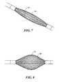
- FIG. 3shows a geometric configuration of an embodiment of a medical device in accordance with the present invention
- FIG. 4depicts an additional geometric configuration of an embodiment of a medical device in accordance with the present invention.
- FIG. 5illustrates another geometric configuration of an embodiment of a medical device in accordance with the present invention
- FIG. 6shows still another geometric configuration of an embodiment of a medical device in accordance with the present invention.
- FIG. 7depicts an additional geometric configuration of an embodiment of a medical device in accordance with the present invention.
- FIG. 8illustrates another geometric configuration of an embodiment of a medical device in accordance with the present invention.
- FIG. 9shows still another geometric configuration of an embodiment of a medical device in accordance with the present invention.
- FIG. 10shows still another geometric configuration of an embodiment of a medical device in accordance with the present invention.
- FIG. 11depicts an additional geometric configuration of an embodiment of a medical device in accordance with the present invention.
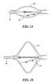
- FIG. 12illustrates another geometric configuration of an embodiment of a medical device in accordance with the present invention.
- FIG. 13shows still another geometric configuration of an embodiment of a medical device in accordance with the present invention.
- FIG. 14depicts an additional geometric configuration of an embodiment of a medical device in accordance with the present invention.
- FIG. 15illustrates an embodiment of a medical device in accordance with the present invention.
- FIG. 16shows an embodiment of a medical device in accordance with the present invention.
- an embodiment of the present inventionprovides a medical device 10 defining an elongate body 12 such as a catheter.
- the elongate body 12may define a proximal portion and a distal portion, and may further include one or more lumens disposed within the elongate body thereby providing mechanical, electrical, and/or fluid communication between the proximal portion of the elongate body 12 and the distal portion of the elongate body.
- the elongate body 12may include an injection lumen 14 and an exhaust lumen defining a fluid flow path therethrough.
- the elongate bodymay include a guidewire lumen 16 extending along at least a portion of the length of the elongate body 12 for over-the-wire applications, where the guidewire lumen 16 may define a proximal end and a distal end.
- the guidewire lumen 16may be disposed within the elongate body 12 such that the distal end of the guidewire lumen 16 extends beyond the and out of the distal portion of the elongate body 12 .
- the elongate body 12may further include a deflection mechanism whereby the elongate body and components coupled thereto may be maneuvered in one or more planes of motion.
- a pull wire with a proximal end and a distal endmay have its distal end anchored to the elongate body at or near the distal end.
- the proximal end of the pull wiremay be anchored to a knob or lever 18 controllable and responsive to an input from an operator or physician.
- the medical device 10 of the present inventionmay include a tip portion 20 towards the distal portion of the elongate body 12 , which may be coupled to a portion of the guidewire lumen 16 .
- the tip portion 20may circumscribe a portion of the distal end of the guidewire lumen 16 .
- the tip portion 20may define a cavity in fluid communication with the injection lumen 14 , yet be isolated from fluid communication with the guidewire lumen 16 , i.e., the tip portion 20 may be able to receive a fluid therein while the guidewire lumen 16 remains excluded form any fluid flow originating and/or flowing through the elongate body 12 of the catheter.
- the tip portion 20may be able to receive a fluid flow, such as a coolant, thereby allowing the tip portion 20 to thermally affect a desired tissue region and/or to create a spot lesion or focalized ablative pattern.
- the medical device 10 of the present inventionmay further include a shaping element 22 coupled to the distal portion of the elongate body 12 that is configurable into a plurality of geometric configurations, such as those shown in FIGS. 3-14 .
- the shaping element 22may define a mesh, braided mesh or wire structure, and may be constructed from a combination of elastic materials, non-elastic materials, and/or shape-memory materials, such as nickel-titanium alloy or the like, for example.
- the term “mesh”is intended to include any element having an openwork fabric or structure, and may include but is not limited to, an interconnected network of wire-like segments, a sheet of material having numerous apertures and/or portions of material removed, or the like.
- a particular geometric configuration of the shaping element 22may be achieved through the application of mechanical force, thermal energy, and/or electrical energy.
- the shaping element 22may be predisposed and/or biased towards a first geometric configuration, which may include a substantially elongated, cylindrical shape.
- the shaping element 22may be selectively transitioned from the first geometric configuration to a second geometric configuration, having a substantially spherical shape, for example.
- the transition from a first particular configuration to a second particular configuration of the shaping element 22may be achieved by the application of mechanical, thermal, or electrical forces. Further, the transition may be a result of particular material properties exhibited by the construction of the shaping element 22 .
- the shaping element 22may include a mesh structure including components made from a shape-memory material, as well as components made from a relatively non-elastic material. The components made from the shape-memory material may be predisposed and/or biased towards a first geometric configuration, while the non-elastic components may be predisposed and/or biased towards a second geometric configuration.
- a first thermal conditionsuch a temperature range between 10° C.
- the shape-memory materialmay be dominant over the non-elastic components, causing the shaping element 22 to retain the first geometric configuration.
- the shape-memory componentsmay become increasingly pliable, thereby allowing the non-elastic components to dominate and causing the shaping element 22 to assume the second geometric configuration.
- a shaping element 22 being configurable into multiple geometric configurationsmay include a shaping element 22 constructed from a single material being predisposed and/or biased towards a first geometric configuration.
- the medical device of the present inventionmay include an actuator element 24 that may impart a mechanical force on the shaping element 22 and/or a component coupled thereto to overcome the predisposition of the shaping element 22 to retain the first geometric configuration.
- the actuator element 24may include a pull wire or the like affixed to a portion of the shaping element 22 and/or portions of the medical device in proximity to the shaping element, such as the guidewire lumen 16 .
- a portion of the shaping element 22may be coupled to a portion of the movable guidewire lumen 16 .
- the guidewire lumen 16may be longitudinally moved in a proximal direction, whereby the predisposed first geometric configuration of the shaping element 22 is attained. However, the guidewire lumen 16 may then be moved in a distal direction, thereby tensioning the shaping element 22 in order to overcome the bias of the shaping element. As a result, the shaping element 22 attains a second geometric configuration different than the first geometric configuration.
- the actuator element 24may include a push rod or other mechanical coupling for imparting a mechanical and/or physical force on the shaping element 22 to overcome and thereby dominate the first geometric configuration that the shaping element 22 may be predisposed to provide. For example, as shown in FIGS.
- a pull wire 25may be coupled to a portion of the shaping element 22 for tensioning and/or loosening of the shaping element 22 during a procedure.
- the shaping element 22may be slideably disposed about the guidewire lumen 16 such that the guidewire lumen 16 remains in place while the shaping element 22 is manipulated into the desired configuration.
- the shaping element 22may be electrically conductive.
- the shaping element 22may be used to provide the ability to map electrical properties of a particular tissue region, such as in the heart, whereby an electrocardiogram may be obtained.
- the shaping element 22may be used to provide a conductive surface for delivering radiofrequency energy to a particular tissue site, and/or to provide the ability to measure a relative impedance and/or resistance for the purpose of fluid leak detection.
- the medical device 10 of the present inventionmay further include an expandable element 26 at least partially disposed on the elongate catheter body 12 , and may further be disposed within a portion of the shaping element 22 .
- the expandable element 26may include a balloon or other expandable structure, which may define a proximal end coupled to the distal portion of the elongate body 12 of the catheter, while further defining a distal end coupled to the tip portion and/or the distal end of the guidewire lumen 16 .
- the expandable element 26may have any of a myriad of shapes, and may further include one or more material layers providing for puncture resistance, radiopacity, or the like.
- the expandable element 26may be in communication with the fluid injection and exhaust lumens of the medical device as described above, i.e., a fluid flow path may provide an inflation fluid, such as a cryogenic fluid or the like, to the interior of the expandable element 26 .
- the expandable element 26may be inflated within the shaping element 22 , thereby conforming to the shape of the shaping element 22 .
- the shaping element 22may be used to provide a guide and/or “shell” within which the expandable element 26 may be inflated to ensure a desired geometric configuration and/or a desired volume.
- the shaping element 22may, therefore, limit certain portions of the expandable element 26 from expanding, while other areas or regions of the expandable element 26 may be stretched. As portions of the expandable element 26 are stretched, the particular thermal properties of that region may change, i.e., the stretched portions may more readily conduct thermal energy than portions of the expandable element 26 that have not been stretched to the same extent, if at all. Accordingly, the shaping element 22 may provide a particular shape or geometric configuration in which particular areas of the expandable element 26 are allowed to stretch to thereby conduct heat more readily, while other portions of the expandable element 26 are not stretched to provide a degree of thermal insulation. As a result, the shaping element 22 and thus the expandable element 26 may be configured to provide varying thermal conductivity to different regions of tissue while the medical device 10 remains in a fixed position.
- the medical device of the present inventionmay be coupled to a console 28 , which may contain a fluid supply and exhaust, as well as various control mechanisms for operation of the medical device 10 .
- An exemplary use of the medical device 10 of the present inventionmay include making multiple ablative lesions having varying geometric shapes and/or dimensions on a desired tissue region.
- the distal portion of the medical device 10may be positioned in proximity to a tissue region to be treated.
- the tip portion 20 of the medical device 10may be subjected to a fluid flow, including a cryogenic coolant or the like, to create a focalized and/or spot lesion within a desired tissue region.
- the shaping element 22 of the medical device 10may be in a first geometric configuration, such as an elongated cylindrical shape, for example.
- a fluidsuch as a cryogenic coolant
- a fluidsuch as a cryogenic coolant
- the expandable element 26may be inflated such that portions of the expandable element protrude through a mesh construct of the shaping element 22 to contact and/or be in position to thermally affect the desired tissue region, while substantially retaining the geometric configuration of the shaping element 22 .
- coolantmay be circulated through the expandable element 26 in order to thermally affect the tissue region and/or to create a tissue lesion having a desired shape, such as a linear tissue lesion.
- the flow of coolant through the expandable element 26may be discontinued such that the expandable element 26 s at least partially deflated.
- the medical device 10may then be repositioned in proximity to a tissue region where additional thermal treatment may be performed.
- the shaping element 22may subsequently be transitioned from the first geometric configuration to the second geometric configuration, which may include a substantially spherical shape, for example. The transition may be achieved by imparting a mechanical, thermal, and/or electrical force on the shaping element, and may further include manipulation of the actuator element 24 .
- the expandable element 26may once again be inflated within the shaping element 22 , using the aforementioned coolant, for example.
- the second geometric configurationmay be used to impart a second tissue lesion and/or thermally affected area having a varied geometric pattern and/or dimension to that of the first tissue lesion, such as a substantially circular shape, for example.
- a shaping elementcapable of more than two configurations may be employed and achieved through a combination of mechanical, thermal, and/or electrical forces, as well as through characteristics provided through material selection in the construction of the shaping element.
- a particular geometric configurationmay include circular, conical, concave, convex, rounded, or flattened features and/or combinations thereof. Accordingly, an embodiment of the medical device of the present invention may be able to provide focal lesions, circular lesions, linear lesions, circumferential lesions, and combinations thereof.
Landscapes
- Health & Medical Sciences (AREA)
- Life Sciences & Earth Sciences (AREA)
- Surgery (AREA)
- Public Health (AREA)
- Animal Behavior & Ethology (AREA)
- Engineering & Computer Science (AREA)
- Biomedical Technology (AREA)
- Heart & Thoracic Surgery (AREA)
- Veterinary Medicine (AREA)
- Nuclear Medicine, Radiotherapy & Molecular Imaging (AREA)
- General Health & Medical Sciences (AREA)
- Otolaryngology (AREA)
- Molecular Biology (AREA)
- Medical Informatics (AREA)
- Vascular Medicine (AREA)
- Anesthesiology (AREA)
- Hematology (AREA)
- Surgical Instruments (AREA)
- Media Introduction/Drainage Providing Device (AREA)
Abstract
Description
Claims (6)
Priority Applications (8)
| Application Number | Priority Date | Filing Date | Title |
|---|---|---|---|
| US11/476,928US9814511B2 (en) | 2006-06-28 | 2006-06-28 | Variable geometry cooling chamber |
| CA2754636ACA2754636C (en) | 2006-06-28 | 2007-06-19 | Variable geometry cooling chamber |
| EP07719991AEP2037993A4 (en) | 2006-06-28 | 2007-06-19 | Variable geometry cooling chamber |
| CA2653716ACA2653716C (en) | 2006-06-28 | 2007-06-19 | Variable geometry cooling chamber |
| PCT/CA2007/001075WO2008000065A1 (en) | 2006-06-28 | 2007-06-19 | Variable geometry cooling chamber |
| US12/609,463US20100114269A1 (en) | 2006-06-28 | 2009-10-30 | Variable geometry balloon catheter and method |
| US15/808,512US10682171B2 (en) | 2006-06-28 | 2017-11-09 | Variable geometry cooling chamber |
| US16/871,165US11633225B2 (en) | 2006-06-28 | 2020-05-11 | Variable geometry cooling chamber |
Applications Claiming Priority (1)
| Application Number | Priority Date | Filing Date | Title |
|---|---|---|---|
| US11/476,928US9814511B2 (en) | 2006-06-28 | 2006-06-28 | Variable geometry cooling chamber |
Related Child Applications (2)
| Application Number | Title | Priority Date | Filing Date |
|---|---|---|---|
| US12/609,463Continuation-In-PartUS20100114269A1 (en) | 2006-06-28 | 2009-10-30 | Variable geometry balloon catheter and method |
| US15/808,512DivisionUS10682171B2 (en) | 2006-06-28 | 2017-11-09 | Variable geometry cooling chamber |
Publications (2)
| Publication Number | Publication Date |
|---|---|
| US20080009851A1 US20080009851A1 (en) | 2008-01-10 |
| US9814511B2true US9814511B2 (en) | 2017-11-14 |
Family
ID=38845064
Family Applications (3)
| Application Number | Title | Priority Date | Filing Date |
|---|---|---|---|
| US11/476,928Expired - Fee RelatedUS9814511B2 (en) | 2006-06-28 | 2006-06-28 | Variable geometry cooling chamber |
| US15/808,512Active2027-04-16US10682171B2 (en) | 2006-06-28 | 2017-11-09 | Variable geometry cooling chamber |
| US16/871,165Active2026-10-14US11633225B2 (en) | 2006-06-28 | 2020-05-11 | Variable geometry cooling chamber |
Family Applications After (2)
| Application Number | Title | Priority Date | Filing Date |
|---|---|---|---|
| US15/808,512Active2027-04-16US10682171B2 (en) | 2006-06-28 | 2017-11-09 | Variable geometry cooling chamber |
| US16/871,165Active2026-10-14US11633225B2 (en) | 2006-06-28 | 2020-05-11 | Variable geometry cooling chamber |
Country Status (4)
| Country | Link |
|---|---|
| US (3) | US9814511B2 (en) |
| EP (1) | EP2037993A4 (en) |
| CA (2) | CA2653716C (en) |
| WO (1) | WO2008000065A1 (en) |
Families Citing this family (26)
| Publication number | Priority date | Publication date | Assignee | Title |
|---|---|---|---|---|
| US9814511B2 (en) | 2006-06-28 | 2017-11-14 | Medtronic Cryocath Lp | Variable geometry cooling chamber |
| US20100114269A1 (en)* | 2006-06-28 | 2010-05-06 | Medtronic Cryocath Lp | Variable geometry balloon catheter and method |
| WO2009114701A1 (en) | 2008-03-13 | 2009-09-17 | Boston Scientific Scimed, Inc. | Cryo-ablation refrigerant distribution catheter |
| US8298218B2 (en)* | 2009-07-29 | 2012-10-30 | Medtronic Cryocath Lp | Compliant balloon |
| US20120089047A1 (en) | 2010-08-05 | 2012-04-12 | Medtronic Vascular, Inc. | Cryoablation apparatuses, systems, and methods for renal neuromodulation |
| JP5922129B2 (en) | 2010-09-22 | 2016-05-24 | アクラレント インコーポレイテッド | Medical device for treatment of sinus opening |
| US20120158104A1 (en) | 2010-10-26 | 2012-06-21 | Medtronic Ardian Luxembourg S.A.R.L. | Neuromodulation cryotherapeutic devices and associated systems and methods |
| US9060754B2 (en) | 2010-10-26 | 2015-06-23 | Medtronic Ardian Luxembourg S.A.R.L. | Neuromodulation cryotherapeutic devices and associated systems and methods |
| US20120283714A1 (en)* | 2011-05-02 | 2012-11-08 | Teresa Ann Mihalik | Methods of treatment with compliant elements and wire structures |
| US20120283715A1 (en)* | 2011-05-02 | 2012-11-08 | Teresa Ann Mihalik | Electrical sensing systems and methods of use for treating tissue |
| US20120283713A1 (en)* | 2011-05-02 | 2012-11-08 | Teresa Ann Mihalik | Compliant sleeves coupled with wire structures for cryoablation |
| CN103619274A (en)* | 2011-05-02 | 2014-03-05 | 美敦力 | Compliant cannula with attached wire structure for cryoablation |
| US9084592B2 (en)* | 2011-07-11 | 2015-07-21 | C2 Therapeutics, Inc. | Focal ablation assembly |
| US9387031B2 (en) | 2011-07-29 | 2016-07-12 | Medtronic Ablation Frontiers Llc | Mesh-overlayed ablation and mapping device |
| US10058312B2 (en)* | 2011-10-26 | 2018-08-28 | Medtronic Cryocath Lp | Systems and methods for cryoadhesive transseptal punctures |
| US9113911B2 (en) | 2012-09-06 | 2015-08-25 | Medtronic Ablation Frontiers Llc | Ablation device and method for electroporating tissue cells |
| WO2015048806A2 (en) | 2013-09-30 | 2015-04-02 | Nidus Medical, Llc | Apparatus and methods for treating rhinitis |
| US9763743B2 (en) | 2014-07-25 | 2017-09-19 | Arrinex, Inc. | Apparatus and method for treating rhinitis |
| US10271899B2 (en) | 2015-03-18 | 2019-04-30 | Medtronic Cryocath Lp | Multi-function device with treatment and sensing capabilities |
| US9861422B2 (en) | 2015-06-17 | 2018-01-09 | Medtronic, Inc. | Catheter breach loop feedback fault detection with active and inactive driver system |
| EP3413822B1 (en) | 2016-02-11 | 2023-08-30 | Arrinex, Inc. | Device for image guided post-nasal nerve ablation |
| CN109600988B (en) | 2016-06-15 | 2021-08-31 | 阿里内克斯股份有限公司 | Devices and methods for treating the lateral surface of the nasal cavity |
| US10939965B1 (en) | 2016-07-20 | 2021-03-09 | Arrinex, Inc. | Devices and methods for treating a nerve of the nasal cavity using image guidance |
| US11253312B2 (en) | 2016-10-17 | 2022-02-22 | Arrinex, Inc. | Integrated nasal nerve detector ablation-apparatus, nasal nerve locator, and methods of use |
| EP3614940B1 (en) | 2017-04-28 | 2024-11-20 | Arrinex, Inc. | Systems for locating blood vessels in the treatment of rhinitis |
| WO2020055728A1 (en)* | 2018-09-10 | 2020-03-19 | Medtronic Vascular, Inc. | Tissue-removing catheter with guidewire detection sensor |
Citations (63)
| Publication number | Priority date | Publication date | Assignee | Title |
|---|---|---|---|---|
| US5071407A (en)* | 1990-04-12 | 1991-12-10 | Schneider (U.S.A.) Inc. | Radially expandable fixation member |
| US5221261A (en)* | 1990-04-12 | 1993-06-22 | Schneider (Usa) Inc. | Radially expandable fixation member |
| US5250069A (en)* | 1987-02-27 | 1993-10-05 | Terumo Kabushiki Kaisha | Catheter equipped with expansible member and production method thereof |
| US5352199A (en)* | 1993-05-28 | 1994-10-04 | Numed, Inc. | Balloon catheter |
| US5409640A (en)* | 1990-10-12 | 1995-04-25 | The Procter & Gamble Company | Cleansing compositions |
| US5423771A (en)* | 1992-12-01 | 1995-06-13 | Intelliwire, Inc. | Flexible elongate device having a distal extremity of adjustable stiffness and method |
| US5447497A (en) | 1992-08-06 | 1995-09-05 | Scimed Life Systems, Inc | Balloon catheter having nonlinear compliance curve and method of using |
| US5536252A (en) | 1994-10-28 | 1996-07-16 | Intelliwire, Inc. | Angioplasty catheter with multiple coaxial balloons |
| US5603731A (en)* | 1994-11-21 | 1997-02-18 | Whitney; Douglass G. | Method and apparatus for thwarting thrombosis |
| US5653684A (en)* | 1992-06-26 | 1997-08-05 | Schneider (Usa), Inc. | Catheter with expandable wire mesh tip |
| US5690670A (en)* | 1989-12-21 | 1997-11-25 | Davidson; James A. | Stents of enhanced biocompatibility and hemocompatibility |
| US5772681A (en) | 1993-03-02 | 1998-06-30 | Metra Aps | Dilation catheter |
| US5779698A (en)* | 1989-01-18 | 1998-07-14 | Applied Medical Resources Corporation | Angioplasty catheter system and method for making same |
| US5799384A (en)* | 1992-03-19 | 1998-09-01 | Medtronic, Inc. | Intravascular radially expandable stent |
| US5836874A (en)* | 1996-04-08 | 1998-11-17 | Ep Technologies, Inc. | Multi-function electrode structures for electrically analyzing and heating body tissue |
| US5846238A (en)* | 1996-01-19 | 1998-12-08 | Ep Technologies, Inc. | Expandable-collapsible electrode structures with distal end steering or manipulation |
| US5853411A (en)* | 1996-01-19 | 1998-12-29 | Ep Technologies, Inc. | Enhanced electrical connections for electrode structures |
| US5868708A (en)* | 1997-05-07 | 1999-02-09 | Applied Medical Resources Corporation | Balloon catheter apparatus and method |
| EP0896211A2 (en) | 1997-08-04 | 1999-02-10 | Gynecare, Inc. | Apparatus and method for leak detection |
| US5871483A (en)* | 1996-01-19 | 1999-02-16 | Ep Technologies, Inc. | Folding electrode structures |
| US5891136A (en)* | 1996-01-19 | 1999-04-06 | Ep Technologies, Inc. | Expandable-collapsible mesh electrode structures |
| US5910154A (en) | 1997-05-08 | 1999-06-08 | Embol-X, Inc. | Percutaneous catheter and guidewire having filter and medical device deployment |
| US5925038A (en)* | 1996-01-19 | 1999-07-20 | Ep Technologies, Inc. | Expandable-collapsible electrode structures for capacitive coupling to tissue |
| US5928193A (en) | 1997-10-03 | 1999-07-27 | Boston Scientific Corporation | Balloon catheterization |
| US5954742A (en)* | 1996-03-16 | 1999-09-21 | Osypka; Peter | Dilatation catheter |
| US6053913A (en)* | 1998-09-10 | 2000-04-25 | Tu; Lily Chen | Rapid exchange stented balloon catheter having ablation capabilities |
| US6081749A (en)* | 1997-08-13 | 2000-06-27 | Surx, Inc. | Noninvasive devices, methods, and systems for shrinking of tissues |
| WO2000042932A1 (en) | 1999-01-25 | 2000-07-27 | Cryocath Technologies, Inc. | Closed loop catheter coolant system |
| US6221006B1 (en)* | 1998-02-10 | 2001-04-24 | Artemis Medical Inc. | Entrapping apparatus and method for use |
| US20010011182A1 (en)* | 1997-11-12 | 2001-08-02 | William Dubrul | Biological passageway occlusion removal |
| US20010012951A1 (en)* | 1999-07-16 | 2001-08-09 | Bates Mark C. | Emboli filtration system having integral strut arrangement and methods of use |
| US6273886B1 (en)* | 1998-02-19 | 2001-08-14 | Curon Medical, Inc. | Integrated tissue heating and cooling apparatus |
| US6283959B1 (en)* | 1999-08-23 | 2001-09-04 | Cyrocath Technologies, Inc. | Endovascular cryotreatment catheter |
| US6312407B1 (en) | 1995-06-05 | 2001-11-06 | Medtronic Percusurge, Inc. | Occlusion of a vessel |
| US20020029052A1 (en)* | 2000-04-07 | 2002-03-07 | Bacchus Vascular, Inc. | Methods and device for percutaneous remote endarterectomy |
| US20020032406A1 (en) | 1996-10-10 | 2002-03-14 | Kusleika Richard S. | Catheter for tissue dilatation and drug delivery |
| US20020045894A1 (en) | 1999-02-24 | 2002-04-18 | Cryovascular Systems, Inc. | Safety cryotherapy catheter |
| US20020123765A1 (en)* | 2000-06-29 | 2002-09-05 | Concentric Medical, Inc. | Systems, methods and devices for removing obstructions from a blood vessel |
| US6547814B2 (en)* | 1998-09-30 | 2003-04-15 | Impra, Inc. | Selective adherence of stent-graft coverings |
| WO2003039338A2 (en) | 2001-11-02 | 2003-05-15 | Imetrx, Inc. | Methods and apparatus for cryo-therapy |
| US20030139803A1 (en)* | 2000-05-30 | 2003-07-24 | Jacques Sequin | Method of stenting a vessel with stent lumenal diameter increasing distally |
| US6626861B1 (en) | 1998-04-22 | 2003-09-30 | Applied Medical Resources | Balloon catheter apparatus and method |
| US6635068B1 (en)* | 1998-02-10 | 2003-10-21 | Artemis Medical, Inc. | Occlusion, anchoring, tensioning and flow direction apparatus and methods for use |
| US20030236533A1 (en)* | 2002-06-20 | 2003-12-25 | The Regents Of The University Of California | Shape memory polymer actuator and catheter |
| US20040020333A1 (en) | 2002-08-01 | 2004-02-05 | Poole Daniel L. | Self adjusting grooved pliers |
| US20040054367A1 (en) | 2002-09-16 | 2004-03-18 | Jimenez Teodoro S. | Ablation catheter having shape-changing balloon |
| US6748953B2 (en)* | 2002-06-11 | 2004-06-15 | Scimed Life Systems, Inc. | Method for thermal treatment of type II endoleaks in arterial aneurysms |
| US6811550B2 (en) | 1999-03-15 | 2004-11-02 | Cryovascular Systems, Inc. | Safety cryotherapy catheter |
| US20040220560A1 (en)* | 2003-04-29 | 2004-11-04 | Briscoe Roderick E. | Endocardial dispersive electrode for use with a monopolar RF ablation pen |
| US20040260333A1 (en)* | 1997-11-12 | 2004-12-23 | Dubrul William R. | Medical device and method |
| US6952615B2 (en) | 2001-09-28 | 2005-10-04 | Shutaro Satake | Radiofrequency thermal balloon catheter |
| US20060009756A1 (en)* | 2004-05-14 | 2006-01-12 | Francischelli David E | Method and devices for treating atrial fibrillation by mass ablation |
| US6989009B2 (en) | 2002-04-19 | 2006-01-24 | Scimed Life Systems, Inc. | Cryo balloon |
| US20060100475A1 (en)* | 2004-11-05 | 2006-05-11 | White Jack C | Expandable brachytherapy device |
| US20060155322A1 (en)* | 2005-01-07 | 2006-07-13 | Medtronic Vascular, Inc. | Distal protection device for filtering and occlusion |
| US7097643B2 (en) | 2003-03-03 | 2006-08-29 | Sinus Rhythm Technologies, Inc. | Electrical block positioning devices and methods of use therefor |
| US20060270982A1 (en) | 2005-05-13 | 2006-11-30 | Mihalik Teresa A | Compliant balloon catheter |
| US20060271093A1 (en) | 2005-05-27 | 2006-11-30 | Holman Thomas J | Fiber mesh controlled expansion balloon catheter |
| US20070106302A1 (en)* | 2005-11-04 | 2007-05-10 | Ethicon Endo-Surgery, Inc | Lumen traversing device |
| US20070129751A1 (en) | 2004-04-21 | 2007-06-07 | Acclarent, Inc. | Devices, systems and methods useable for treating frontal sinusitis |
| WO2008000065A1 (en) | 2006-06-28 | 2008-01-03 | Cryocath Technologies Inc. | Variable geometry cooling chamber |
| US20080172084A1 (en)* | 2007-01-11 | 2008-07-17 | Ev3 Inc. | Convertible embolic protection devices and methods of use |
| US20110213403A1 (en)* | 2010-02-23 | 2011-09-01 | Maria Aboytes | Devices and methods for vascular recanalization |
Family Cites Families (6)
| Publication number | Priority date | Publication date | Assignee | Title |
|---|---|---|---|---|
| US5255679A (en)* | 1992-06-02 | 1993-10-26 | Cardiac Pathways Corporation | Endocardial catheter for mapping and/or ablation with an expandable basket structure having means for providing selective reinforcement and pressure sensing mechanism for use therewith, and method |
| US6640120B1 (en)* | 2000-10-05 | 2003-10-28 | Scimed Life Systems, Inc. | Probe assembly for mapping and ablating pulmonary vein tissue and method of using same |
| DE202004021953U1 (en)* | 2003-09-12 | 2013-06-19 | Vessix Vascular, Inc. | Selectable eccentric remodeling and / or ablation of atherosclerotic material |
| US7727228B2 (en)* | 2004-03-23 | 2010-06-01 | Medtronic Cryocath Lp | Method and apparatus for inflating and deflating balloon catheters |
| US20100114269A1 (en)* | 2006-06-28 | 2010-05-06 | Medtronic Cryocath Lp | Variable geometry balloon catheter and method |
| CN108652736B (en)* | 2012-05-18 | 2022-06-10 | 努瓦拉公司 | Compact delivery pulmonary treatment system and method of improving pulmonary function |
- 2006
- 2006-06-28USUS11/476,928patent/US9814511B2/ennot_activeExpired - Fee Related
- 2007
- 2007-06-19EPEP07719991Apatent/EP2037993A4/ennot_activeWithdrawn
- 2007-06-19CACA2653716Apatent/CA2653716C/ennot_activeExpired - Fee Related
- 2007-06-19CACA2754636Apatent/CA2754636C/ennot_activeExpired - Fee Related
- 2007-06-19WOPCT/CA2007/001075patent/WO2008000065A1/enactiveApplication Filing
- 2017
- 2017-11-09USUS15/808,512patent/US10682171B2/enactiveActive
- 2020
- 2020-05-11USUS16/871,165patent/US11633225B2/enactiveActive
Patent Citations (67)
| Publication number | Priority date | Publication date | Assignee | Title |
|---|---|---|---|---|
| US5250069A (en)* | 1987-02-27 | 1993-10-05 | Terumo Kabushiki Kaisha | Catheter equipped with expansible member and production method thereof |
| US5779698A (en)* | 1989-01-18 | 1998-07-14 | Applied Medical Resources Corporation | Angioplasty catheter system and method for making same |
| US5690670A (en)* | 1989-12-21 | 1997-11-25 | Davidson; James A. | Stents of enhanced biocompatibility and hemocompatibility |
| US5221261A (en)* | 1990-04-12 | 1993-06-22 | Schneider (Usa) Inc. | Radially expandable fixation member |
| US5496277A (en)* | 1990-04-12 | 1996-03-05 | Schneider (Usa) Inc. | Radially expandable body implantable device |
| US5071407A (en)* | 1990-04-12 | 1991-12-10 | Schneider (U.S.A.) Inc. | Radially expandable fixation member |
| US5409640A (en)* | 1990-10-12 | 1995-04-25 | The Procter & Gamble Company | Cleansing compositions |
| US5799384A (en)* | 1992-03-19 | 1998-09-01 | Medtronic, Inc. | Intravascular radially expandable stent |
| US5653684A (en)* | 1992-06-26 | 1997-08-05 | Schneider (Usa), Inc. | Catheter with expandable wire mesh tip |
| US5447497A (en) | 1992-08-06 | 1995-09-05 | Scimed Life Systems, Inc | Balloon catheter having nonlinear compliance curve and method of using |
| US5423771A (en)* | 1992-12-01 | 1995-06-13 | Intelliwire, Inc. | Flexible elongate device having a distal extremity of adjustable stiffness and method |
| US5772681A (en) | 1993-03-02 | 1998-06-30 | Metra Aps | Dilation catheter |
| US5352199A (en)* | 1993-05-28 | 1994-10-04 | Numed, Inc. | Balloon catheter |
| US5536252A (en) | 1994-10-28 | 1996-07-16 | Intelliwire, Inc. | Angioplasty catheter with multiple coaxial balloons |
| US5603731A (en)* | 1994-11-21 | 1997-02-18 | Whitney; Douglass G. | Method and apparatus for thwarting thrombosis |
| US6312407B1 (en) | 1995-06-05 | 2001-11-06 | Medtronic Percusurge, Inc. | Occlusion of a vessel |
| US5871483A (en)* | 1996-01-19 | 1999-02-16 | Ep Technologies, Inc. | Folding electrode structures |
| US5925038A (en)* | 1996-01-19 | 1999-07-20 | Ep Technologies, Inc. | Expandable-collapsible electrode structures for capacitive coupling to tissue |
| US5846238A (en)* | 1996-01-19 | 1998-12-08 | Ep Technologies, Inc. | Expandable-collapsible electrode structures with distal end steering or manipulation |
| US5853411A (en)* | 1996-01-19 | 1998-12-29 | Ep Technologies, Inc. | Enhanced electrical connections for electrode structures |
| US5891136A (en)* | 1996-01-19 | 1999-04-06 | Ep Technologies, Inc. | Expandable-collapsible mesh electrode structures |
| US5954742A (en)* | 1996-03-16 | 1999-09-21 | Osypka; Peter | Dilatation catheter |
| US5836874A (en)* | 1996-04-08 | 1998-11-17 | Ep Technologies, Inc. | Multi-function electrode structures for electrically analyzing and heating body tissue |
| US20020032406A1 (en) | 1996-10-10 | 2002-03-14 | Kusleika Richard S. | Catheter for tissue dilatation and drug delivery |
| US5868708A (en)* | 1997-05-07 | 1999-02-09 | Applied Medical Resources Corporation | Balloon catheter apparatus and method |
| US5910154A (en) | 1997-05-08 | 1999-06-08 | Embol-X, Inc. | Percutaneous catheter and guidewire having filter and medical device deployment |
| EP0896211A2 (en) | 1997-08-04 | 1999-02-10 | Gynecare, Inc. | Apparatus and method for leak detection |
| US6081749A (en)* | 1997-08-13 | 2000-06-27 | Surx, Inc. | Noninvasive devices, methods, and systems for shrinking of tissues |
| US5928193A (en) | 1997-10-03 | 1999-07-27 | Boston Scientific Corporation | Balloon catheterization |
| US6517514B1 (en) | 1997-10-03 | 2003-02-11 | Boston Scientific Corporation | Balloon catheterization |
| US20040260333A1 (en)* | 1997-11-12 | 2004-12-23 | Dubrul William R. | Medical device and method |
| US20010011182A1 (en)* | 1997-11-12 | 2001-08-02 | William Dubrul | Biological passageway occlusion removal |
| US6221006B1 (en)* | 1998-02-10 | 2001-04-24 | Artemis Medical Inc. | Entrapping apparatus and method for use |
| US6635068B1 (en)* | 1998-02-10 | 2003-10-21 | Artemis Medical, Inc. | Occlusion, anchoring, tensioning and flow direction apparatus and methods for use |
| US6273886B1 (en)* | 1998-02-19 | 2001-08-14 | Curon Medical, Inc. | Integrated tissue heating and cooling apparatus |
| US6626861B1 (en) | 1998-04-22 | 2003-09-30 | Applied Medical Resources | Balloon catheter apparatus and method |
| US6053913A (en)* | 1998-09-10 | 2000-04-25 | Tu; Lily Chen | Rapid exchange stented balloon catheter having ablation capabilities |
| US6547814B2 (en)* | 1998-09-30 | 2003-04-15 | Impra, Inc. | Selective adherence of stent-graft coverings |
| WO2000042932A1 (en) | 1999-01-25 | 2000-07-27 | Cryocath Technologies, Inc. | Closed loop catheter coolant system |
| US20020045894A1 (en) | 1999-02-24 | 2002-04-18 | Cryovascular Systems, Inc. | Safety cryotherapy catheter |
| US6811550B2 (en) | 1999-03-15 | 2004-11-02 | Cryovascular Systems, Inc. | Safety cryotherapy catheter |
| US20010012951A1 (en)* | 1999-07-16 | 2001-08-09 | Bates Mark C. | Emboli filtration system having integral strut arrangement and methods of use |
| US6283959B1 (en)* | 1999-08-23 | 2001-09-04 | Cyrocath Technologies, Inc. | Endovascular cryotreatment catheter |
| US20020029052A1 (en)* | 2000-04-07 | 2002-03-07 | Bacchus Vascular, Inc. | Methods and device for percutaneous remote endarterectomy |
| US20030139803A1 (en)* | 2000-05-30 | 2003-07-24 | Jacques Sequin | Method of stenting a vessel with stent lumenal diameter increasing distally |
| US20020123765A1 (en)* | 2000-06-29 | 2002-09-05 | Concentric Medical, Inc. | Systems, methods and devices for removing obstructions from a blood vessel |
| US6952615B2 (en) | 2001-09-28 | 2005-10-04 | Shutaro Satake | Radiofrequency thermal balloon catheter |
| WO2003039338A2 (en) | 2001-11-02 | 2003-05-15 | Imetrx, Inc. | Methods and apparatus for cryo-therapy |
| US6989009B2 (en) | 2002-04-19 | 2006-01-24 | Scimed Life Systems, Inc. | Cryo balloon |
| US6748953B2 (en)* | 2002-06-11 | 2004-06-15 | Scimed Life Systems, Inc. | Method for thermal treatment of type II endoleaks in arterial aneurysms |
| US20030236533A1 (en)* | 2002-06-20 | 2003-12-25 | The Regents Of The University Of California | Shape memory polymer actuator and catheter |
| US20040020333A1 (en) | 2002-08-01 | 2004-02-05 | Poole Daniel L. | Self adjusting grooved pliers |
| US20040054367A1 (en) | 2002-09-16 | 2004-03-18 | Jimenez Teodoro S. | Ablation catheter having shape-changing balloon |
| US7097643B2 (en) | 2003-03-03 | 2006-08-29 | Sinus Rhythm Technologies, Inc. | Electrical block positioning devices and methods of use therefor |
| US20040220560A1 (en)* | 2003-04-29 | 2004-11-04 | Briscoe Roderick E. | Endocardial dispersive electrode for use with a monopolar RF ablation pen |
| US20090138008A1 (en)* | 2003-04-29 | 2009-05-28 | Medtronic, Inc. | Endocardial Dispersive Electrode for Use with a Monopolar RF Ablation Pen |
| US7497857B2 (en)* | 2003-04-29 | 2009-03-03 | Medtronic, Inc. | Endocardial dispersive electrode for use with a monopolar RF ablation pen |
| US20070129751A1 (en) | 2004-04-21 | 2007-06-07 | Acclarent, Inc. | Devices, systems and methods useable for treating frontal sinusitis |
| US20060009756A1 (en)* | 2004-05-14 | 2006-01-12 | Francischelli David E | Method and devices for treating atrial fibrillation by mass ablation |
| US20060100475A1 (en)* | 2004-11-05 | 2006-05-11 | White Jack C | Expandable brachytherapy device |
| US20060155322A1 (en)* | 2005-01-07 | 2006-07-13 | Medtronic Vascular, Inc. | Distal protection device for filtering and occlusion |
| US20060270982A1 (en) | 2005-05-13 | 2006-11-30 | Mihalik Teresa A | Compliant balloon catheter |
| US20060271093A1 (en) | 2005-05-27 | 2006-11-30 | Holman Thomas J | Fiber mesh controlled expansion balloon catheter |
| US20070106302A1 (en)* | 2005-11-04 | 2007-05-10 | Ethicon Endo-Surgery, Inc | Lumen traversing device |
| WO2008000065A1 (en) | 2006-06-28 | 2008-01-03 | Cryocath Technologies Inc. | Variable geometry cooling chamber |
| US20080172084A1 (en)* | 2007-01-11 | 2008-07-17 | Ev3 Inc. | Convertible embolic protection devices and methods of use |
| US20110213403A1 (en)* | 2010-02-23 | 2011-09-01 | Maria Aboytes | Devices and methods for vascular recanalization |
Also Published As
| Publication number | Publication date |
|---|---|
| WO2008000065A1 (en) | 2008-01-03 |
| EP2037993A4 (en) | 2009-09-02 |
| CA2653716C (en) | 2011-12-20 |
| CA2754636C (en) | 2014-06-03 |
| US20180064482A1 (en) | 2018-03-08 |
| EP2037993A1 (en) | 2009-03-25 |
| US20200268429A1 (en) | 2020-08-27 |
| CA2754636A1 (en) | 2008-01-03 |
| US20080009851A1 (en) | 2008-01-10 |
| CA2653716A1 (en) | 2008-01-03 |
| US11633225B2 (en) | 2023-04-25 |
| US10682171B2 (en) | 2020-06-16 |
Similar Documents
| Publication | Publication Date | Title |
|---|---|---|
| US11633225B2 (en) | Variable geometry cooling chamber | |
| CA2776924C (en) | Variable geometry balloon catheter and method | |
| US10383677B2 (en) | Balloon catheter with deformable fluid delivery conduit | |
| EP2459090B1 (en) | Configurable treatment balloon having variable tension and shape | |
| US9220555B2 (en) | Cryo-ablation device with deployable injection tube | |
| US20120283715A1 (en) | Electrical sensing systems and methods of use for treating tissue | |
| CA2834749C (en) | Compliant sleeves coupled with wire structures for cryoablation | |
| US20120283713A1 (en) | Compliant sleeves coupled with wire structures for cryoablation | |
| US20120283714A1 (en) | Methods of treatment with compliant elements and wire structures |
Legal Events
| Date | Code | Title | Description |
|---|---|---|---|
| AS | Assignment | Owner name:CRYOCATH TECHNOLOGIES INC., CANADA Free format text:ASSIGNMENT OF ASSIGNORS INTEREST;ASSIGNORS:WITTENBERGER, DAN;ABBOUD, MARWAN;DEAC, IOANA;SIGNING DATES FROM 20060725 TO 20060802;REEL/FRAME:018282/0230 Owner name:CRYOCATH TECHNOLOGIES INC., CANADA Free format text:ASSIGNMENT OF ASSIGNORS INTEREST;ASSIGNORS:WITTENBERGER, DAN;ABBOUD, MARWAN;DEAC, IOANA;REEL/FRAME:018282/0230;SIGNING DATES FROM 20060725 TO 20060802 | |
| AS | Assignment | Owner name:MEDTRONIC CRYOCATH LP, CANADA Free format text:ASSIGNMENT OF ASSIGNORS INTEREST;ASSIGNOR:CRYOCATH TECHNOLOGIES INC.;REEL/FRAME:023119/0651 Effective date:20090814 Owner name:MEDTRONIC CRYOCATH LP,CANADA Free format text:ASSIGNMENT OF ASSIGNORS INTEREST;ASSIGNOR:CRYOCATH TECHNOLOGIES INC.;REEL/FRAME:023119/0651 Effective date:20090814 | |
| FEPP | Fee payment procedure | Free format text:ENTITY STATUS SET TO UNDISCOUNTED (ORIGINAL EVENT CODE: BIG.) | |
| STCF | Information on status: patent grant | Free format text:PATENTED CASE | |
| FEPP | Fee payment procedure | Free format text:MAINTENANCE FEE REMINDER MAILED (ORIGINAL EVENT CODE: REM.); ENTITY STATUS OF PATENT OWNER: LARGE ENTITY | |
| LAPS | Lapse for failure to pay maintenance fees | Free format text:PATENT EXPIRED FOR FAILURE TO PAY MAINTENANCE FEES (ORIGINAL EVENT CODE: EXP.); ENTITY STATUS OF PATENT OWNER: LARGE ENTITY | |
| STCH | Information on status: patent discontinuation | Free format text:PATENT EXPIRED DUE TO NONPAYMENT OF MAINTENANCE FEES UNDER 37 CFR 1.362 | |
| FP | Lapsed due to failure to pay maintenance fee | Effective date:20211114 |