US9814499B2 - Intramedullary fracture fixation devices and methods - Google Patents
Intramedullary fracture fixation devices and methodsDownload PDFInfo
- Publication number
- US9814499B2 US9814499B2US14/861,355US201514861355AUS9814499B2US 9814499 B2US9814499 B2US 9814499B2US 201514861355 AUS201514861355 AUS 201514861355AUS 9814499 B2US9814499 B2US 9814499B2
- Authority
- US
- United States
- Prior art keywords
- aperture
- bone
- fastener
- screw
- actuator
- Prior art date
- Legal status (The legal status is an assumption and is not a legal conclusion. Google has not performed a legal analysis and makes no representation as to the accuracy of the status listed.)
- Active, expires
Links
Images


Classifications
- A—HUMAN NECESSITIES
- A61—MEDICAL OR VETERINARY SCIENCE; HYGIENE
- A61B—DIAGNOSIS; SURGERY; IDENTIFICATION
- A61B17/00—Surgical instruments, devices or methods
- A61B17/56—Surgical instruments or methods for treatment of bones or joints; Devices specially adapted therefor
- A61B17/58—Surgical instruments or methods for treatment of bones or joints; Devices specially adapted therefor for osteosynthesis, e.g. bone plates, screws or setting implements
- A61B17/68—Internal fixation devices, including fasteners and spinal fixators, even if a part thereof projects from the skin
- A61B17/72—Intramedullary devices, e.g. pins or nails
- A61B17/7233—Intramedullary devices, e.g. pins or nails with special means of locking the nail to the bone
- A—HUMAN NECESSITIES
- A61—MEDICAL OR VETERINARY SCIENCE; HYGIENE
- A61B—DIAGNOSIS; SURGERY; IDENTIFICATION
- A61B17/00—Surgical instruments, devices or methods
- A61B17/16—Instruments for performing osteoclasis; Drills or chisels for bones; Trepans
- A61B17/17—Guides or aligning means for drills, mills, pins or wires
- A61B17/1725—Guides or aligning means for drills, mills, pins or wires for applying transverse screws or pins through intramedullary nails or pins
- A—HUMAN NECESSITIES
- A61—MEDICAL OR VETERINARY SCIENCE; HYGIENE
- A61B—DIAGNOSIS; SURGERY; IDENTIFICATION
- A61B17/00—Surgical instruments, devices or methods
- A61B17/56—Surgical instruments or methods for treatment of bones or joints; Devices specially adapted therefor
- A61B17/58—Surgical instruments or methods for treatment of bones or joints; Devices specially adapted therefor for osteosynthesis, e.g. bone plates, screws or setting implements
- A61B17/68—Internal fixation devices, including fasteners and spinal fixators, even if a part thereof projects from the skin
- A61B17/683—Internal fixation devices, including fasteners and spinal fixators, even if a part thereof projects from the skin comprising bone transfixation elements, e.g. bolt with a distal cooperating element such as a nut
- A—HUMAN NECESSITIES
- A61—MEDICAL OR VETERINARY SCIENCE; HYGIENE
- A61B—DIAGNOSIS; SURGERY; IDENTIFICATION
- A61B17/00—Surgical instruments, devices or methods
- A61B17/56—Surgical instruments or methods for treatment of bones or joints; Devices specially adapted therefor
- A61B17/58—Surgical instruments or methods for treatment of bones or joints; Devices specially adapted therefor for osteosynthesis, e.g. bone plates, screws or setting implements
- A61B17/68—Internal fixation devices, including fasteners and spinal fixators, even if a part thereof projects from the skin
- A61B17/72—Intramedullary devices, e.g. pins or nails
- A61B17/7208—Flexible pins, e.g. ENDER pins
- A—HUMAN NECESSITIES
- A61—MEDICAL OR VETERINARY SCIENCE; HYGIENE
- A61B—DIAGNOSIS; SURGERY; IDENTIFICATION
- A61B17/00—Surgical instruments, devices or methods
- A61B17/56—Surgical instruments or methods for treatment of bones or joints; Devices specially adapted therefor
- A61B17/58—Surgical instruments or methods for treatment of bones or joints; Devices specially adapted therefor for osteosynthesis, e.g. bone plates, screws or setting implements
- A61B17/68—Internal fixation devices, including fasteners and spinal fixators, even if a part thereof projects from the skin
- A61B17/72—Intramedullary devices, e.g. pins or nails
- A61B17/7233—Intramedullary devices, e.g. pins or nails with special means of locking the nail to the bone
- A61B17/7258—Intramedullary devices, e.g. pins or nails with special means of locking the nail to the bone with laterally expanding parts, e.g. for gripping the bone
- A61B17/7266—Intramedullary devices, e.g. pins or nails with special means of locking the nail to the bone with laterally expanding parts, e.g. for gripping the bone with fingers moving radially outwardly
- A—HUMAN NECESSITIES
- A61—MEDICAL OR VETERINARY SCIENCE; HYGIENE
- A61B—DIAGNOSIS; SURGERY; IDENTIFICATION
- A61B17/00—Surgical instruments, devices or methods
- A61B17/56—Surgical instruments or methods for treatment of bones or joints; Devices specially adapted therefor
- A61B17/58—Surgical instruments or methods for treatment of bones or joints; Devices specially adapted therefor for osteosynthesis, e.g. bone plates, screws or setting implements
- A61B17/68—Internal fixation devices, including fasteners and spinal fixators, even if a part thereof projects from the skin
- A61B17/84—Fasteners therefor or fasteners being internal fixation devices
- A61B17/846—Nails or pins, i.e. anchors without movable parts, holding by friction only, with or without structured surface
- A61B17/848—Kirschner wires, i.e. thin, long nails
- A—HUMAN NECESSITIES
- A61—MEDICAL OR VETERINARY SCIENCE; HYGIENE
- A61B—DIAGNOSIS; SURGERY; IDENTIFICATION
- A61B17/00—Surgical instruments, devices or methods
- A61B17/56—Surgical instruments or methods for treatment of bones or joints; Devices specially adapted therefor
- A61B17/58—Surgical instruments or methods for treatment of bones or joints; Devices specially adapted therefor for osteosynthesis, e.g. bone plates, screws or setting implements
- A61B17/68—Internal fixation devices, including fasteners and spinal fixators, even if a part thereof projects from the skin
- A61B17/84—Fasteners therefor or fasteners being internal fixation devices
- A61B17/86—Pins or screws or threaded wires; nuts therefor
- A—HUMAN NECESSITIES
- A61—MEDICAL OR VETERINARY SCIENCE; HYGIENE
- A61B—DIAGNOSIS; SURGERY; IDENTIFICATION
- A61B90/00—Instruments, implements or accessories specially adapted for surgery or diagnosis and not covered by any of the groups A61B1/00 - A61B50/00, e.g. for luxation treatment or for protecting wound edges
- A61B90/03—Automatic limiting or abutting means, e.g. for safety
- A61B2090/031—Automatic limiting or abutting means, e.g. for safety torque limiting
Definitions
- Embodiments of the present inventionrelate to devices, tools and methods for providing reinforcement of bones. More specifically, the present invention relates to devices, tools and methods for providing reconstruction and reinforcement of bones, including diseased, osteoporotic and/or fractured bones.
- Bone fracturesare a common medical condition both in the young and old segments of the population.
- osteoporosishas become more of a significant medical concern in part due to the risk of osteoporotic fractures.
- Osteoporosis and osteoarthritisare among the most common conditions to affect the musculoskeletal system, as well as frequent causes of locomotor pain and disability. Osteoporosis can occur in both human and animal subjects (e.g. horses).
- Osteoporosis (OP) and osteoarthritis (OA)occur in a substantial portion of the human population over the age of fifty.
- One current treatment of bone fracturesincludes surgically resetting the fractured bone. After the surgical procedure, the fractured area of the body (i.e., where the fractured bone is located) is often placed in an external cast for an extended period of time to ensure that the fractured bone heals properly. This can take several months for the bone to heal and for the patient to remove the cast before resuming normal activities.
- an intramedullary (IM) rod or nailis used to align and stabilize the fracture.
- IMintramedullary
- a metal rodis placed inside a canal of a bone and fixed in place, typically at both ends.
- FixionTM IMNail
- Placement of conventional IM rodsare typically a “line of sight” and require access collinear with the center line of the IM canal. Invariably, this line of sight access violates, disrupts, and causes damage to important soft tissue structures such as ligaments, tendons, cartilage, fascia, and epidermis. This approach requires incision, access to the canal, and placement of the IM nail. The nail can be subsequently removed or left in place.
- a conventional IM nail procedurerequires a similar, but possibly larger, opening to the space, a long metallic nail being placed across the fracture, and either subsequent removal, and or when the nail is not removed, a long term implant of the IM nail.
- the outer diameter of the IM nailmust be selected for the minimum inside diameter of the space. Therefore, portions of the IM nail may not be in contact with the canal. Further, micro-motion between the bone and the IM nail may cause pain or necrosis of the bone. In still other cases, infection can occur.
- the IM nailmay be removed after the fracture has healed. This requires a subsequent surgery with all of the complications and risks of a later intrusive procedure. In general, rigid IM rods or nails are difficult to insert, can damage the bone and require additional incisions for cross-screws to attach the rods or nails to the bone.
- the bone fixation devicemay include an elongate body with a longitudinal axis, and/or having a flexible state and a rigid state.
- the devicefurther may include a plurality of grippers disposed at longitudinally-spaced locations along the elongate body, a rigid hub connected to the elongate body, and an actuator that is operably-connected to the grippers to deploy the grippers from a first shape to an expanded second shape.
- the elongate body and the rigid hubmay or may not be collinear or parallel.
- a bone fixation deviceis provided with an elongate body; an oblong aperture in the elongate body configured to accept a screw; an bone engaging mechanism disposed within the elongate body; an actuator operably connected to the bone engaging mechanism to actuate the bone engaging mechanism from a disengaged configuration to an engaged configuration, wherein the actuator comprises a ramped surface that is slideably coupled to an interior surface of the bone engaging mechanism, wherein proximally moving the ramped surface of the actuator causes the ramped surface to slideably engage the interior surface of the bone engaging mechanism at an angle thereby pivoting the bone engaging mechanism away from the elongate body to deploy the bone engaging mechanism into the engaged configuration; and wherein the screw is configured to be pushed from a first position within the oblong aperture to a second position within the oblong aperture to reduce a fracture.
- a screw driverconfigured to engage with a corresponding hex socket
- the screw driveris provided with a shaft having a proximal end and a distal end; the distal end having a hex tip comprising at least six flats and a slot bisecting at least two of the six flats; and wherein the hex tip is deformed outward to create an interference with the corresponding hex socket.
- One such methodcomprises providing an elongate fixation device having a proximal end, a distal end, an oblong aperture, and a radially expandable gripper; extending the radially expandable gripper away from the elongate fixation device by moving a ramped surface of an actuator head toward the proximal end thereby engaging the radially expandable gripper with a surface of an intramedullary canal of a first bone segment; inserting a first screw into a second bone segment and through the oblong aperture; and translating the first screw to reduce a distance between the first bone segment and the second bone segment.
- a system for installing a screwincluding a bone fixation device having an elongate body; an oblong aperture in the elongate body configured to accept the screw, a bone engaging mechanism, and an actuator operably coupled to the bone engaging mechanism to actuate the bone engaging mechanism from a disengaged configuration to an engaged configuration; and a combination tool operably connected to the elongate body, wherein the combination tool comprises at least one bore configured to align with the oblong aperture in the elongate body.
- One such methodcomprises providing an elongate body having an oblong aperture and a bone engaging mechanism; coupling the elongate body with a combination tool having a first bore configured to accept a K-wire; extending the elongate body into a canal of the bone of the first bone segment; extending the K-wire through the first bore and into the second bone segment; and manipulating the combination tool to reposition the first bone segment relative to the second bone segment.
- One such methodcomprises extending a first K-wire into the first bone segment and a second K-wire into the second bone segment; coupling the first K-wire and the second K-wire to a distractor; manipulating the distractor to reposition the first bone segment relative to the second bone segment; reaming a canal in the first bone segment and the second bone segment; coupling an elongate body having an oblong aperture with a combination tool; and inserting the elongate body into the canal.
- a reamer configured to be used with boneis provided with a shaft having a proximal end and a distal end; the distal end having at least one spiral cutting edge having a first diameter; the proximal end having a handle; and wherein a portion of the shaft has a diameter less than the first diameter.
- a method of using a bone fixation deviceincluding the steps of providing an elongate body having a bone engaging mechanism; extending the elongate body into a canal of a bone; and actuating the bone engaging mechanism from a disengaged configuration to an engaged configuration, wherein in the engaged configuration, the bone engaging mechanism pivots away from the elongate body to deploy the bone engaging mechanism against the wall of the canal.
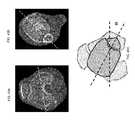
- a method of inserting a devicecan include the step of inserting a device within the intramedullary canal of a fibula, the device comprising one or more apertures.
- the methodcan include the step of inserting a first fastener through the device in a lateral-medial direction.
- the methodcan include the step of inserting a second fastener through the device, the second screw angled from the first screw by angle alpha.
- the methodcan include the step of inserting a third fastener through the device, the third screw angled from the first screw by angle beta, wherein the third screw extends into the tibia.
- the methodcan include the step of actuating a mechanism of the device to grip the intramedullary canal of a fibula.
- angle alphais between 45-75 degrees. In some embodiments, angle beta is between 10-40 degrees.
- the methodcan include the step of translating the first fastener within an aperture of the device toward the mechanism.
- the methodcan include the step of rotating the first fastener, wherein the rotation of the first fastener causes translation of the first fastener within an aperture of the device toward the mechanism.
- actuating the mechanismcomprises deflecting three members towards the intramedullary canal.
- the first fastener and the second fastenerare contained within the fibula.
- the third fasteneris a screw.
- the methodcan include the step of passing at least one of the first fastener, the second fastener, and the third fastener through an aperture in a tool aligned with an aperture in the device.
- the methodcan include the step of inserting K-wires within bones portion near a fracture and rotating the bone portions using the K-wires.
- rotating the bone portionsfurther comprises rotating a knob of a distractor.
- a devicein some embodiments, can include an elongate body comprising at least a first aperture, a second aperture and a third aperture. In some embodiments, the elongate body sized to be inserted within the fibula.
- the devicecan include a first fastener configured to be inserted through the first aperture in a lateral-medial direction.
- the devicecan include a second fastener configured to be inserted through the second aperture. In some embodiments, the second aperture angled from the first aperture by angle alpha.
- the devicecan include a third fastener configured to be inserted through the third aperture. In some embodiments, the third aperture angled from the first screw by angle beta. In some embodiments, the third fastener has a longer length than the first fastener and the second fastener.
- the devicecan include an actuator configured to actuate a portion of the device to grip the intramedullary canal of a fibula.
- angle alphais 60 degrees. In some embodiments, angle beta is 25 degrees.
- the first apertureis oblong, wherein the first fastener is configured to translate within the first aperture toward the actuator. In some embodiments, the portion comprises three members configured to deflect towards the intramedullary canal. In some embodiments, the first fastener and the second fastener are sized to be contained within the fibula. In some embodiments, the third fastener is sized to extend into the tibia. In some embodiments, the third fastener is a screw.
- the devicecan include a tool comprising at least a fourth aperture aligned with the first aperture, a fifth aperture aligned with the second aperture and a sixth aperture aligned with the third aperture.
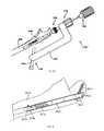
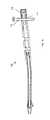
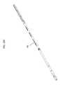
- FIG. 1is a perspective view of an embodiment of a bone fixation device implanted in a bone.
- FIG. 2is another perspective view of the implanted device of FIG. 1 .
- FIG. 3is a longitudinal cross-section view of the bone fixation device of FIG. 1 in a non-deployed state.
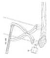
- FIG. 4is a plan view of a combination deployment tool that may be used with the bone fixation device of FIG. 1 .
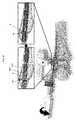
- FIG. 5is a cross-section view of the tool and device shown in FIG. 4 .
- FIG. 6is a perspective view of the tool and device shown in FIG. 4 .
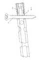
- FIG. 7Ais a cross-section view of the implanted device of FIG. 1 .
- FIG. 7Bis a plan view of an alternative combination deployment tool that may be used with the bone fixation device of FIG. 1 .
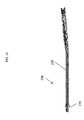
- FIG. 8is a perspective view of an alternative embodiment of the implanted device of FIG. 1 .
- FIG. 9is a perspective view of another alternative embodiment of the implanted device of FIG. 1 .
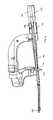
- FIG. 10Ais a perspective view of another embodiment of a bone fixation device shown deployed in a fractured clavicle.
- FIG. 10Bis perspective view of the device shown in FIG. 10A shown in a deployed state.
- FIG. 10Cis a side elevation view of the device shown in FIG. 10A shown in a retracted or undeployed state.
- FIG. 10Dis a side elevation view of the device shown in FIG. 10A shown in a deployed state.
- FIG. 10Eis a cross-sectional view of the device shown in FIG. 10A shown in a retracted or undeployed state.
- FIG. 10Fis a cross-sectional view of the device shown in FIG. 10A shown in a deployed state.
- FIG. 10Gis a perspective view of a gripper of the device shown in FIG. 10A shown in a retracted or undeployed state.
- FIG. 10His a side elevation view of a gripper and actuator of the device shown in FIG. 10A shown in a retracted or undeployed state.
- FIG. 10Iis a perspective view of a gripper and actuator of the device shown in FIG. 10A shown in a deployed state.
- FIG. 11is perspective view of another embodiment of a bone fixation device shown in a retracted or undeployed state.
- FIG. 12is perspective view of the device shown in FIG. 11 shown in a deployed state.
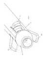
- FIG. 13is perspective view of the distal end of the device shown in FIG. 12 shown in a deployed state.
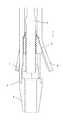
- FIG. 14is a cross-sectional view of the device shown in FIG. 12 shown in a deployed state.
- FIG. 15is a cross-sectional view of the distal end of the device shown in FIG. 12 shown in a deployed state.
- FIG. 16Ais perspective view of the device shown in FIG. 12 shown in a deployed state prior to insertion of a screw.
- FIG. 16Bis perspective view of the device shown in FIG. 16A shown in a deployed state during insertion of the screw.
- FIG. 16Cis perspective view of the device shown in FIG. 16A shown in a deployed state after translation of the screw.
- FIG. 17is a cross-sectional view of the device shown in FIG. 16C shown in a deployed state after translation of the screw.
- FIG. 18is a cross-sectional view of the device shown in FIG. 16C shown in a deployed state after insertion of a cap.
- FIG. 19is a cross-sectional view of the proximal end of the device shown in FIG. 18 shown in a deployed state after insertion of a cap.
- FIG. 20is a perspective view of the another embodiment of a bone fixation device shown in a deployed state
- FIG. 21is a perspective view of an embodiment of a tool.
- FIG. 22is a perspective view the tool shown in FIG. 21 coupled to the bone fixation device of FIG. 12
- FIG. 23is a perspective view of the system shown in FIG. 22 shown in a deployed state during insertion of the screw.
- FIG. 24is cross-sectional view of the system shown in FIG. 22 shown in a deployed state during insertion of the screw.
- FIG. 25is cross-sectional view of the system shown in FIG. 22 shown in a deployed state after translation of the screw.
- FIG. 26is cross-sectional view of the proximal end of the system shown in FIG. 22 shown in a deployed state after translation of the screw.
- FIG. 27is cross-sectional view of the proximal end of the system shown in FIG. 22 shown in a deployed state after insertion of a cap.
- FIG. 28Ais a perspective view of the device shown in FIG. 16A during insertion of the screw.
- FIG. 28Bis a perspective view of the device shown in FIG. 16A shown in a deployed state after translation of the screw.
- FIG. 29is a perspective view of an embodiment of a screw driver.
- FIG. 30is a perspective view of the distal end of the screw driver of FIG. 29 .
- FIGS. 31A-31Iare various views of entry points of the tibia to implant the device of FIGS. 1-30 .
- FIGS. 32A-32Jare various method steps to implant the device of FIGS. 1-30 .
- FIGS. 33A-33Gare various steps of methods to implant the device of FIGS. 1-30 .
- FIGS. 34A-34Dare various steps of methods to implant the device of FIGS. 1-30 .
- FIGS. 35A-35Bare perspective views of another embodiment of a bone fixation device shown in a deployed state.
- FIG. 36is a perspective view of the distal end of the device shown in FIG. 35A in a deployed state.
- FIG. 37is a longitudinal cross-section view of the bone fixation device of FIG. 35A in a deployed state
- FIGS. 38A-38Dare schematic views of the device shown in FIG. 35A .
- FIGS. 39A-39Bare perspective views of the proximal end of the device shown in FIG. 35A .
- FIG. 40is a perspective view of the device shown in FIG. 35A during insertion of a compression screw.
- FIGS. 41A-41Bare perspective views of the device shown in FIG. 35A shown in a deployed state during syndesmosis fixation.
- FIG. 42is a view of the anatomy.
- FIGS. 43A-43Care views of the anatomy.
- FIGS. 44A-44Sare various method steps to implant the device of FIGS. 35-41B .
- FIGS. 45A-45Oare various tools to implant the device of FIGS. 35-41B .
- boneis often described as a specialized connective tissue that serves three major functions anatomically.
- boneprovides a mechanical function by providing structure and muscular attachment for movement.
- boneprovides a metabolic function by providing a reserve for calcium and phosphate.
- boneprovides a protective function by enclosing bone marrow and vital organs.
- Bonescan be categorized as long bones (e.g. radius, femur, tibia and humerus) and flat bones (e.g. skull, scapula and mandible). Each bone type has a different embryological template. Further each bone type contains cortical and trabecular bone in varying proportions.
- the devices of this inventioncan be adapted for use in any of the bones of the body as will be appreciated by those skilled in the art.
- Cortical boneforms the shaft, or diaphysis, of long bones and the outer shell of flat bones.
- the cortical boneprovides the main mechanical and protective function.
- the trabecular bone(cancellous) is found at the end of the long bones, or the epiphysis, and inside the cortex of flat bones.
- the trabecular boneconsists of a network of interconnecting trabecular plates and rods and is the major site of bone remodeling and resorption for mineral homeostasis. During development, the zone of growth between the epiphysis and diaphysis is the metaphysis.
- woven bonewhich lacks the organized structure of cortical or cancellous bone, is the first bone laid down during fracture repair.
- the bone segmentsare positioned in proximity to each other in a manner that enables woven bone to be laid down on the surface of the fracture.
- This description of anatomy and physiologyis provided in order to facilitate an understanding of the invention. Persons of skill in the art will also appreciate that the scope and nature of the invention is not limited by the anatomy discussion provided. Further, it will be appreciated there can be variations in anatomical characteristics of an individual patient, as a result of a variety of factors, which are not described herein. Further, it will be appreciated there can be variations in anatomical characteristics between bones which are not described herein.
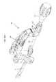
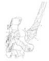
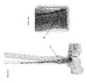
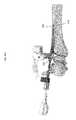
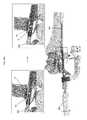
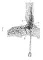
- FIGS. 1 and 2are perspective views of an embodiment of a bone fixation device 3100 having a proximal end 3102 (nearest the surgeon) and a distal end 3104 (further from surgeon) and positioned within the bone space of a patient according to the invention.
- device 3100is shown implanted in the upper (or proximal) end of an ulna 3106 .
- the proximal end and distal endrefers to the position of an end of the device relative to the remainder of the device or the opposing end as it appears in the drawing.
- the proximal endcan be used to refer to the end manipulated by the user or physician.
- the distal endcan be used to refer to the end of the device that is inserted and advanced within the bone and is furthest away from the physician.
- proximal and distalcould change in another context, e.g. the anatomical context in which proximal and distal use the patient as reference, or where the entry point is distal from the surgeon.
- the deviceWhen implanted within a patient, the device can be held in place with suitable fasteners such as wire, screws, nails, bolts, nuts and/or washers.
- the device 3100is used for fixation of fractures of the proximal or distal end of long bones such as intracapsular, intertrochanteric, intercervical, supracondular, or condular fractures of the femur; for fusion of a joint; or for surgical procedures that involve cutting a bone.
- the devices 3100may be implanted or attached through the skin so that a pulling force (traction may be applied to the skeletal system).
- the design of the metaphyseal fixation device 3100 depictedis adapted to provide a bone engaging mechanism or gripper 3108 adapted to engage target bone of a patient from the inside of the bone.
- the deviceis designed to facilitate bone healing when placed in the intramedullary space within a post fractured bone.
- This device 3100has a gripper 3108 positioned distally and shown deployed radially outward against the wall of the intramedullary cavity. On entry into the cavity, gripper 3108 is flat and retracted ( FIG. 3 ). Upon deployment, gripper 3108 pivots radially outward and grips the diaphyseal bone from the inside of the bone.
- a flexible-to-rigid body portion 3114may also be provided, and in this embodiment is positioned between gripper 3108 and hub 3112 . It may be provided with wavy spiral cuts 3116 for that purpose, as will be described in more detail below.
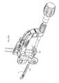
- FIG. 3shows a longitudinal cross-section of device 3100 in a non-deployed configuration.
- gripper 3108includes two pairs of opposing bendable gripping members 3118 . Two of the bendable gripping members 3118 are shown in FIG. 3 , while the other two (not shown in FIG. 3 ) are located at the same axial location but offset by 90 degrees. Each bendable gripping member 3118 has a thinned portion 3120 that permits bending as the opposite distal end 3122 of member 3118 is urged radially outward, such that member 3118 pivots about thinned portion 3120 . When extended, distal ends 3122 of bendable members 3118 contact the inside of the bone to anchor the distal portion of device 3100 to the bone.
- the grippermay comprise 1, 2, 3, 4, 5, 6 or more bendable members similar to members 3118 shown.
- bendable members 3118 of gripper 3108are urged radially outward by a ramped surface on actuator head 3124 .
- Actuator head 3124is formed on the distal end of actuator 3126 .
- the proximal end of actuator 3126is threaded to engage a threaded bore of drive member 3128 .
- the proximal end of drive member 3128is provided with a keyed socket 3130 for receiving the tip of a rotary driver tool 3132 (shown in FIG. 5 ) through the proximal bore of device 3100 .
- rotary driver tool 3132turns drive member 3128
- actuator 3126is drawn in a proximal direction to outwardly actuate gripper members 3118 .
- a hemispherical tip cover 3134may be provided at the distal end of the device as shown to act as a blunt obturator. This arrangement facilitates penetration of bone (e.g. an intramedullary space) by device 3100 while keeping the tip of device 3100 from digging into bone during insertion.
- bonee.g. an intramedullary space
- device 3100may include one or more flexible-to-rigid body portions 3114 .
- This featureis flexible upon entry into bone and rigid upon application of compressive axial force provided by tensioning actuator 3126 .
- Various embodiments of a flexible-to-rigid portionmay be used, including dual helical springs whose inner and outer tubular components coil in opposite directions, a chain of ball bearings with flats or roughened surfaces, a chain of cylinders with flats, features, cones, spherical or pointed interdigitating surfaces, wavy-helical cut tubes, two helical cut tubes in opposite directions, linear wires with interdigitating coils, and bellows-like structures.
- the design of the flexible-to-rigid tubular body portion 3114allows a single-piece design to maximize the transformation of the same body from a very flexible member that minimizes strength in bending to a rigid body that maximizes strength in bending and torsion.
- the flexible membertransforms to a rigid member when compressive forces are applied in the axial direction at each end, such as by an actuator similar to 3126 .
- the body portion 3114is made, for example, by a near-helical cut 3116 on a tubular member at an angle of incidence to the axis somewhere between 0 and 180 degrees from the longitudinal axis of the tubular body portion 3114 .
- the near-helical cut or wavy-helical cutmay be formed by the superposition of a helical curve added to a cyclic curve that produces waves of frequencies equal or greater than zero per turn around the circumference and with cyclic amplitude greater than zero.
- the waves of one segmentnest with those on either side of it, thus increasing the torque, bending strength and stiffness of the tubular body when subjective to compressive forces.
- the tapered surfaces formed by the incident angleallow each turn to overlap or interdigitate with the segment on either side of it, thus increasing the bending strength when the body is in compression.
- the cutscan be altered in depth and distance between the cuts on the longitudinal axis along the length of body portion 3114 to variably alter the flexible-to-rigid characteristics of the tubular body along its length.
- the cuts 3116 in body portion 3114allow an otherwise rigid member to increase its flexibility to a large degree during deployment.
- the tubular membercan have constant or varying internal and external diameters. This design reduces the number of parts of the flexible-to-rigid body portion of the device and allows insertion and extraction of the device through a curved entry port in the bone while maximizing its rigidity once inserted.
- Application and removal of compressive forces provided by a parallel member such as wire(s), tension ribbons, a sheath, wound flexible cable, or actuator 3126 as shownwill transform the body from flexible to rigid and vice versa.
- body portion 3114changes from being flexible to rigid to better secure the bone fracture.
- Rotating drive member 3128 in the opposite directioncauses body portion 3114 to change from a rigid to a flexible state, such as for removing device 3100 if needed in the initial procedure or during a subsequent procedure after the bone fracture(s) have partially or completely healed.
- Body portion 3114may be provided with a solid longitudinal portion 3136 (as seen in FIGS.
- cuts 3116are a series of individual cuts each traversing less than 360 degrees in circumference, rather than a single, continuous helical cut.
- This solid portion 3136can aid in removal of device 3100 by keeping body portion 3114 from extending axially like a spring.
- FIG. 4illustrates a combination tool 3138 useful for inserting device 3100 , actuating gripper 3108 , compressing flexible-to-rigid body portion 3114 , approximating the fracture in bone 3106 , aligning anchor screw(s) 3110 , and removing device 3100 , if desired.
- tool 3138includes an L-shaped body 3140 that mounts the other components of the tool and also serves as a handle.
- the main components of tool 3138are a device attachment portion 3142 , a rotary driver 3132 , an approximating driver 3144 , and a screw alignment portion 3146 .
- FIG. 5shows a cross-section of the tool 3138 and device 3100 illustrated in FIG. 4 .
- device attachment portion 3142includes a knob 3148 rigidly coupled to a tube 3150 which is rotatably mounted within sleeve 3152 .
- Sleeve 3152in turn is fixedly mounted to tool body 3140 .
- the distal end of tube 3150is provided with external threads for engaging the internal threads on the proximal end of device 3100 .
- both the distal end of sleeve 3152 and the proximal end of device 3100may be provided with semicircular steps that inter-engage to prevent device 3100 from rotating with respect to sleeve 3152 .
- device 3100can be prevented from rotating when it is secured to tool 3138 by tube 3150 of device attachment portion 3142 .
- the mating semicircular stepsalso serve to position device 3100 in a particular axial and angular orientation with respect to tool 3138 for aligning screws with screw holes, as will be later described.
- Rotary driver 3132may be used to actuate gripper 3108 and compress flexible-to-rigid body portion 3114 after device 3100 is inserted into bone 3106 .
- Driver 3132may also be used to allow body portion 3114 to decompress and gripper 3108 to retract if removal of device 3100 from bone 3106 is desired.
- driver 3132includes knob 3154 , torsion spring 3156 , hub 3158 , bushing 3160 and shaft 3162 .
- the distal end of shaft 3162is provided with a mating tip 3164 , such as one having a hex-key shape, for engaging with keyed socket 3130 of device 3100 (seen in FIG. 3 ), such that turning driver shaft 3162 turns drive member 3128 and axially actuates actuator 3126 , as described above.
- the proximal end of shaft 3162may be fitted with a bushing 3160 , such as with a press-fit.
- Hub 3158may be secured over bushing 3160 , such as with a pin through bushing 3160 and shaft 3162 .
- knob 3154is rotatably mounted over hub 3158 and bushing 3160 such that knob 3154 can rotate independently from shaft 3162 .
- a torsion spring 3156may be used to couple knob 3154 to hub 3158 as shown to create a torque limiting and/or torque measuring driver. With this indirect coupling arrangement, as knob 3154 is rotated about shaft 3162 , spring 3156 urges hub 3158 and shaft 3162 to rotate in the same direction.
- Rotational resistance applied by device 3100 to shaft tip 3164will increase in this embodiment as gripper 3108 engages bone 3106 , and flexible-to-rigid body portion 3114 compresses. As more torque is applied to knob 3154 , it will advance rotationally with respect to hub 3158 as torsion spring 3156 undergoes more stress. Markings may be provided on knob 3154 and hub 3158 to indicate the torque being applied. In this manner, a surgeon can use driver 3132 to apply torque to device 3100 in a predetermined range. This can help ensure that gripper 3108 is adequately set in bone 3106 , body portion 3114 is sufficiently compressed, and excessive torque is not being applied that might damage device 3100 , bone 3106 or cause slippage therebetween.
- a slip clutch or other mechanismmay be provided to allow the applied torque to be limited or indicated.
- driver 3132may be configured to “click” into or out of a detent position when a desired torque is reached, thus allowing the surgeon to apply a desired torque without needing to observe any indicia on the driver.
- the driver knobmay be selectably or permanently coupled to shaft 3162 directly.
- the approximating driver portion 3144 of tool 3138may be used to compress one or more fractures in bone 3106 .
- Approximating driver 3144includes knob 3166 located on sleeve 3152 .
- Knob 3166may be knurled on an outer circumference, and have threads on at least a portion of its axial bore. The internal threads of knob 3166 engage with mating external threads on sleeve 3152 such that when knob 3166 is rotated it advances axially with respect to sleeve 3152 .
- sleeve 3152is prevented from moving away from the bone.
- knob 3166As knob 3166 is advanced axially toward bone 3106 , it serves to approximate bone fractures located between gripper 3108 and knob 3166 . Suitable thread pitch and knob circumference may be selected to allow a surgeon to supply a desired approximating force to bone 3106 by using a reasonable rotation force on knob 3166 . In alternative embodiments (not shown), a torque indicating and/or torque limiting mechanism as described above may be incorporated into approximating driver 3144 .
- tool 3138may also include a screw alignment portion 3146 .
- alignment portion 3146includes a removable alignment tube 3168 and two bores 3170 and 3172 through tool body 3140 .
- a single bore or more than two boresmay be used, with or without the use of separate alignment tube(s).
- alignment tube 3168is first received in bore 3170 as shown. In this position, tube 3168 is in axial alignment with angled hole 3174 at the distal end 3102 of device 3100 . As described above, the mating semicircular steps of device 3100 and sleeve 3152 position angled hole 3174 in its desired orientation. With this arrangement, a drill bit, screw driver, screw and/or other fastening device or tool may be inserted through the bore of tube 3168 such that the device(s) are properly aligned with hole 3174 . The outward end of alignment tube 3168 may also serve as a depth guide to stop a drill bit, screw and/or other fastener from penetrating bone 3106 beyond a predetermined depth.
- Alignment tube 3168may be withdrawn from bore 3170 as shown, and inserted in bore 3172 . In this position, tube 3168 aligns with hole 3176 of device 3100 . As described above, a drill bit, screw driver, screw and/or other fastening device may be inserted through the bore of tube 3168 such that the device(s) are properly aligned with hole 3176 .
- FIG. 6shows alignment tube 3168 of tool 3138 aligning screw 3110 with angled hole 3174 at the distal end of device 3100 , as described above.
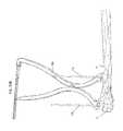
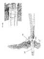
- FIG. 7Ashows a first screw 3110 received through angled hole 3174 and a second screw 3110 received through hole 3176 in device 3100 and into bone 3106 .
- Screws 3110may be installed manually or with the aid of tool 3138 as described above.
- the heads of screws 3110may be configured to be self-countersinking such that they remain substantially beneath the outer surface of the bone when installed, as shown, so as to not interfere with adjacent tissue.
- the proximal end 3102 of device 3100is secured to bone 3106 with two screws 3110 , and the distal end 3104 is secured by gripper 3108 . In this manner, any bone fractures located between the proximal screw 3110 and distal gripper 3108 may be approximated and rigidly held together by device 3100 .
- more than one grippermay be used, or only screws or other fasteners without grippers may be used to secure device 3100 within bone 3106 .
- the device shown in FIG. 1could be configured with a second gripper located between screw 3110 and the middle of the device if the fracture is located more at the mid-shaft of the bone.
- more than two screws or other fastenersmay be used, or only grippers without fasteners may be used.
- holes such as 3174 and 3176 as shown and described abovecan be preformed in the implantable device. In other embodiments, some or all of the holes can be drilled or otherwise formed in situ after the device is implanted in the bone.
- combination tool 3138may be removed by turning knob 3148 to disengage threads of tube 3150 from threads within the proximal end 3102 of device 3100 .
- An end plug 3178may be threaded into the proximal end 3102 of device 3100 to preventing growth of tissue into implanted device 3100 .
- Device 3100may be left in bone 3106 permanently, or it may be removed by performing the above described steps in reverse. In particular, plug 3178 is removed, tool 3138 is attached, screws 3110 are removed, gripper 3108 is retracted, and device 3100 is pulled out using tool 3138 .
- FIG. 7Bshows an alternative embodiment of a combination tool 3138 ′ useful for inserting device 3100 , actuating gripper 3108 , compressing flexible-to-rigid body portion 3114 , approximating the fracture in bone 3106 , aligning anchor screw(s) 3110 , and removing device 3100 , if desired.
- exemplary tool 3138 ′includes an L-shaped body 3140 ′ that mounts the other components of the tool and also serves as a handle.
- the main components of tool 3138 ′are a device attachment portion 3142 , a rotary driver 3132 , an approximating driver 3144 , and a screw alignment portion 3146 .
- Tool 3138 ′is constructed to allow one or more screw holes to be formed in vivo, and/or allow screw(s) to be aligned with such screw holes or preformed screw holes, through flexible-to-rigid body portion 3114 of device 3100 .
- Tool 3138 ′may be configured to allow the screw hole(s) may be formed at an angle through body portion 3114 , and/or formed perpendicularly to the longitudinal axis of device 3100 .
- Tool 3138 ′may also include the capability to form screw holes or align screws for insertion in the proximal hub portion of device 3100 as described above.
- Tool 3138 ′may be used to form screw hole(s) in flexible-to-rigid body portion 3114 by guiding a drill bit with alignment tube 3168 .
- Screw hole(s)may also be formed directly in body portion 3114 without pre-forming or drilling holes in vivo, but by placing a screw directly into body portion 3114 , such as with a self-tapping screw guided with alignment tube 3168 .
- Internal components within device 3100may be configured such that screw(s) pass though it or pass around it.
- the actuatorcomprises one or more cables, leaving enough room within body portion 3114 so that a screw can avoid the actuator(s), or move it/them out of the way when passing into or through body portion 3114 .
- the one or more actuatorsare large enough to allow one or more screws to pass through it/them without impeding the operation of the actuator(s).
- the screw(s)only enter one wall of tubular body portion 3114 without entering the interior space of the body portion.
- FIGS. 8 and 9show alternative embodiments similar to device 3100 described above.
- Device 3100 ′ shown in FIG. 8is essentially identical to device 3100 described above but is shorter in length and utilizes a single anchor screw 3110 at its proximal end 3102 .
- Device 3100 ′′ shown in FIG. 9is similar to device 3100 ′, but is shorter still.
- the devicesmay be configured to have a nominal diameter of 3 mm, 4 mm, 5 mm or 6 mm. It is envisioned that all three device designs 3100 , 3100 ′ and 3100 ′′ may each be provided in all three diameters such that the chosen device is suited for the particular fracture(s) and anatomy in which it is implanted.
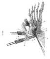
- FIGS. 10A-10Ishow another embodiment of a bone fixation device constructed according to aspects of the invention.
- FIG. 10Ais a perspective view showing the exemplary device 3200 deployed in a fractured clavicle 3202 .
- Device 3200is similar to device 3100 described above and shown in FIGS. 1-7A , but has a gripper 3204 located near its proximal end, another gripper 3206 located at a more distal location, and a flexible-to-rigid body portion 3208 located near the distal end of the device.
- a bone screw 3210 and gripper 3204are configured to secure device 3200 inside bone 3202 on the proximal side of fracture 3212
- gripper 3206 and flexible-to-rigid body portion 3208are configured to secure device 3200 on the distal side of fracture 3212 .
- construction and operation of device 3200is much like that of device 3100 described above.
- each of the two grippers 3204 and 3206has four outwardly expanding arms 3214 . These arms are spaced at 90 degree intervals around the circumference of the device body.
- the arms 3214 of gripper 3204may be offset by 45 degrees from arms 3214 of gripper 3206 as shown in the figures to distribute the forces applied by grippers 3204 and 3206 on the bone 3202 .
- a single actuator 3216may be used to deploy both grippers 3204 and 3206 .
- Actuator 3216may also be used to axially compress flexible-to-rigid body portion 3208 to make it substantially rigid.
- At least a portion of actuator 3216may be flexible to allow flexible-to-rigid body portion 3208 to assume a curved shape, as seen in FIGS. 10A and 10B .
- the actuatormay be rigid and faulted with the desired straight and/or curved shape to match the flexible-to-rigid body portion.
- FIGS. 10G-10Ifurther details of an exemplary gripper 3204 are shown.
- FIGS. 10G and 10Hshow gripper 3204 with bendable arms 3214 in a retracted state.
- cam 3218 of actuator 3216is driven axially into the distal ramped ends of arms 3214 , arms 3214 bend at thinned portions 3220 to move radially outward toward the deployed position shown in FIG. 10I .
- Notches 3222may be provided in the distal ends of arms 3214 as shown to allow arms 3214 to better grip interior bone surfaces. Without departing from the scope of the invention, one, two, three, or more bendable arms may be used.
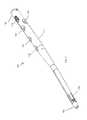
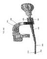
- FIGS. 11 and 12are perspective views of an embodiment of a bone fixation device 100 having a proximal end 102 (nearest the surgeon) and a distal end 104 (further from surgeon) and positioned within the bone space of a patient according to the invention.
- device 100is configured to be implanted in the fibula, but other configurations for other bony segments are contemplated.
- the proximal end and distal endrefers to the position of an end of the device relative to the remainder of the device or the opposing end as it appears in the drawing.
- the proximal endcan be used to refer to the end manipulated by the user or physician.
- the distal endcan be used to refer to the end of the device that is inserted and advanced within the bone and is furthest away from the physician.
- proximal and distalcould change in another context, e.g. the anatomical context in which proximal and distal use the patient as reference, or where the entry point is distal from the surgeon.
- the deviceWhen implanted within a patient, the device can be held in place with suitable fasteners such as wire, screws, nails, bolts, nuts and/or washers.
- the device 100is used for fixation of fractures of the proximal or distal end of long bones such as intracapsular, intertrochanteric, intercervical, supracondular, or condular fractures of the fibula; for fusion of a joint; or for surgical procedures that involve cutting a bone.
- the devices 100may be implanted or attached through the skin so that a pulling force (traction may be applied to the skeletal system).
- the design of the fixation device 100 depictedis adapted to provide a bone engaging mechanism or gripper 108 adapted to engage target bone of a patient from the inside of the bone.
- the device 100is designed to facilitate bone healing when placed in the intramedullary space within a post fractured bone.
- This device 100has a gripper 108 positioned distally and shown deployed radially outward against the wall of the intramedullary cavity. On entry into the cavity, gripper 108 is flat and retracted ( FIG. 11 ). Upon deployment, gripper 108 pivots radially outward and grips the diaphyseal bone from the inside of the bone.
- the device 100can include a hub 112 comprising one or more aperture 114 , 116 .
- One or more screws 110 placed through apertures 114 , 116 through the hub 112lock the device 100 to the bone, as described below. Hence, the metaphysis and the diaphysis are joined.
- FIGS. 12-13shows a perspective view of the device 100 in a deployed configuration.
- gripper 108includes three opposing bendable gripping members 118 .
- Three bendable gripping members 118are shown in FIG. 12 , each located at the same axial location but offset by 120 degrees.
- Each bendable gripping member 118has a thinned portion 120 that permits bending as the opposite distal end 122 of bendable gripping member 118 is urged radially outward, such that bendable gripping member 118 pivots about thinned portion 120 .
- distal ends 122 of bendable members 118contact the inside of the bone to anchor the distal portion of device 100 to the bone.
- the grippermay comprise 1, 2, 3, 4, 5, 6 or more bendable gripping members similar to bendable gripping members 118 shown.
- FIG. 13shows a hemispherical tip cover 134 may be provided at the distal end 104 of the device 100 to act as a blunt obturator. This arrangement facilitates penetration of bone (e.g. an intramedullary space) by device 100 while keeping the tip of device 100 from digging into bone during insertion.
- bonee.g. an intramedullary space
- FIG. 14shows a longitudinal cross-sectional view of the device 100 in a deployed configuration.
- FIG. 15shows the distal end of the device 100 .
- bendable gripping members 118 of gripper 108are urged radially outward by a ramped surface on actuator head 124 .
- Actuator head 124is threaded onto the distal end of actuator 126 .
- the proximal end of actuator 126has a keyed socket 130 for receiving the tip of the tip of a screw driver through the proximal bore of device 100 .
- the keyed socket 130is hex shaped. As screw driver turns actuator 126 , a threaded surface of the actuator 126 rotates in relation to the actuator head 124 .
- the actuator head 124This causes the actuator head 124 to be drawn in a proximal direction toward the proximal end 102 of the device 100 as the actuator head 124 traverses the threaded surface of the actuator 126 .
- the ramped surface on the actuator head 124outwardly actuates bendable gripping members 118 .
- the device 100may include a stop to prevent translation of the actuator 126 .
- the actuator 126may include one or more bends to match the shape of the device 100 .
- the actuatormay 126 may be flexible or have a flexible portion between the keyed socket 130 and the threaded surface. In other embodiments, the actuator 126 is integrally formed with the actuator head 124 .
- the actuator head 124As a tool pulls the actuator 126 , the actuator head 124 is drawn in a proximal direction toward the proximal end 102 of the device 100 .
- the ramped surface on the actuator head 124outwardly actuates bendable gripping members 118 .
- FIG. 16A-Cillustrates a method of inserting the screw 110 into the aperture 114 .
- the screw 110can be inserted with a combination tool, described herein.
- the screw 110is aligned with the aperture 114 .
- the screw 110is oriented perpendicular to the longitudinal axis of the hub 112 .
- the aperture 114has at least one dimension greater that the diameter of the screw 110 .
- the at least one dimensioncan be aligned with the longitudinal axis of the hub 112 and/or the longitudinal axis of the device 100 .
- the aperture 114can be generally oblong, elliptical or tear shaped. The shape of the aperture 114 allows the screw 110 to translate within the aperture 114 .
- the screw 110can be inserted into the aperture 114 near the proximal end 102 of the device 100 .
- the screwcan be translated toward the distal end 104 of the device 100 while within the aperture 114 .
- FIG. 16Bshows the screw 110 inserted in the aperture 114 near the proximal end 102 of the device 100 .
- FIG. 16Cshows the screw 110 translated within the aperture 114 toward the distal end 104 of the device 100 .
- FIGS. 17-19shows a longitudinal cross-sectional view of the device 100 of FIG. 16C after the screw 110 has been translated.
- a cap 128can be provided to maintain the position of the screw 110 .
- the cap 128can prevent the screw 110 from translating within the aperture 114 toward the proximal end 102 of the device 100 .
- the cap 128can be inserted within the proximal bore of the device 100 until the distal end of the cap abuts the screw 110 .
- the proximal borecan be threaded and the cap 128 can include complementary threads. Other configurations of caps 128 are contemplated.
- FIG. 20shows a perspective view of the device 100 ′.
- Device 100 ′is substantially similar to device 100 described above.
- the shape of the body of the device 100 ′has a different taper near the distal end of the hub 112 ′
- FIGS. 21-22shows a top and a side view of a combination tool 138 useful for inserting device 100 , actuating gripper 108 , approximating the fracture in bone, aligning one or more anchor screw(s) 110 , and/or removing device 100 , if desired.
- the main components of tool 138are a hub 158 , a T-shaped body 140 , a device attachment portion 142 , a rotary driver 132 , and an alignment tube 168 .
- the combination tool 138can be assembled as follows.
- Hub 158is configured to abut the proximal end 102 of the device 100 (seen in FIG. 22 ).
- the proximal end 102includes a notch and the hub 158 includes a protrusion.
- Hub 158is coupled to the T-shaped body 140 .
- the hub 158is integrally formed with the T-shaped body 140 .
- hub 158is coupled to the T-shaped body 140 with a lock (shown in FIG. 24 ).
- T-shaped body 140couples with the hub 158 and can also serves as a handle.
- Device attachment portion 142prevents removal of the hub 158 and the T-shaped body from the device 100 .
- Device attachment portion 142includes a knob 152 connected with a tube 160 (seen in FIG. 25-26 ).
- the distal end of the tube 160has a mating configuration 166 to engage the proximal bore of the device 100 (shown in FIG. 26 ).
- the mating configuration 166is threads that engaging the threaded proximal bore of the device 100 .
- the knob 152facilitates rotation of the tube 160 .
- the tube 160 of the device attachment portion 142is inserted into the hub 158 until the mating configuration 166 of the tube 160 engages the proximal bore of the device 100 .
- the tube 160is partially inserted within proximal bore of the device 100 prior to inserting the screw 110 .
- the tube 160does not obstruct the aperture 114 prior to inserting the screw 110 .
- Further rotation of the knob 152causes the knob 152 to abut the T-shaped body 140 .
- the knob 152 of the device attachment portion 142rigidly couples the hub 158 and the T-shaped body 140 with the device 100 .
- the rotary driver 132can be partially inserted within the device attachment portion 142 prior to inserting the screw 110 .
- the rotary driver 132can be inserted within the device attachment portion 142 after inserting the screw 110 .
- the device attachment portion 142has a lock that prevents translation of the rotatory driver 132 prior to inserting the screw 110 .
- the lockcan be released by rotating the lock within the device attachment portion 142 until the lock no longer prevents translation of the shaft 162 .
- the lockcan ensure that the shaft 162 is not obstructing the aperture 114 prior to inserting the screw 110 .
- the alignment tube 168is shown in FIGS. 21-23 .
- the alignment tube 168can be coupled to the T-shaped body 140 .
- the combination tool 138is in place when the device attachment portion 142 rigidly couples the hub 158 and the T-shaped body 140 to the device 100 .
- the removable alignment tube 168aligns with the proximal end of the aperture 114 .
- the T-shaped body 140includes a plurality of bores 170 , 172 . In alternative embodiments (not shown), a single bore or more than two bores may be used, with or without the use of separate alignment tube(s).
- the alignment tube 168may include one or more slots.
- the alignment tube 168includes two longitudinally extending slots 174 .
- the alignment tube 168can be oversized to create an interference between the alignment tube 168 and the bore 170 .
- the slots 174allow the alignment tube 168 to compress to fit within the bore 170 .
- the design of the alignment tube 168allows the alignment tube 168 to be retained within the T-shaped body 140 and be held rigidly in place.
- alignment tube 168is first received in bore 170 (seen in FIG. 21 ). In this position, alignment tube 168 is in axial alignment with aperture 114 at the proximal end 102 of device 100 . As described above, the mating configuration of device 100 and hub 158 position aperture 114 in its desired orientation. With this arrangement, a drill bit, screw driver, screw and/or other fastening device or tool may be inserted through the bore of alignment tube 168 such that the device(s) are properly aligned with aperture 114 . The outward end of alignment tube 168 may also serve as a depth guide to stop a drill bit, screw and/or other fastener from penetrating bone beyond a predetermined depth. FIG.
- FIG. 22shows alignment tube 168 with aperture 114 at the distal end of device 100 , as described above. Inserting the screw 110 through the alignment tube 168 ensures that the screw 110 will have the placement as shown in FIG. 16B .
- the alignment tube 168allows proper placement of the screw 110 even if the aperture 114 or other portions of the device 100 are obstructed from the view of the surgeon.
- the T-shaped body 140includes other bores 172 that align with apertures 116 .
- Alignment tube 168may be withdrawn from bore 170 as shown, and inserted in another bore 172 .
- the alignment tube 168can be inserted within these bores 172 to align and insert other screws 110 into apertures 116 . In this position, alignment tube 168 aligns with aperture 116 of device 100 .
- a drill bit, screw driver, screw and/or other fastening devicemay be inserted through the bore of alignment tube 168 such that the device(s) are properly aligned with aperture 116 .
- FIGS. 23-24show a screw 110 received through aperture 114 .
- Screws 110may be installed manually or with the aid of tool 138 as described above.
- the heads of screws 110may be configured to be self-countersinking such that they remain substantially beneath the outer surface of the bone when installed, as shown, so as to not interfere with adjacent tissue.
- the rotatory driver 132remains stationary during insertion of the screw 110 .
- the rotatory driver 132does not obstruct the aperture 114 .
- FIG. 25-26show the rotatory driver 132 may be used to translate the screw 110 within the aperture 114 .
- rotatory driver 132includes knob 154 and shaft 162 .
- the distal end of shaft 162is provided with a mating configuration 164 , such as threads, for engaging with device attachment portion 142 .
- the mating configurationcan prevent disengagement between the device attachment portion 142 and the rotatory driver 132 .
- Suitable thread pitch and knob circumferencemay be selected to allow a surgeon to supply a desired force to the screw 100 by using a reasonable rotation force on knob 154 .
- the threadsare removed.
- the knob 154can be translated toward the distal end 104 of the device 100 instead of rotating the knob 154 .
- the device attachment portion 142can act as a bearing to align the shaft 126 with the proximal bore of the device 100 .
- a torque indicating and/or torque limiting mechanism as described abovemay be incorporated into the device attachment portion 142 and/or rotatory driver 132 .
- FIG. 16shows the position of the screw 110 after translation within the aperture 114 .
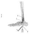
- FIG. 28A-28Billustrates a method of inserting the screw 110 into the aperture 114 in relation to bone segments 2 and 4 .
- Bone segment 2is near the proximal end 102 of the device 100 .
- Bone segment 4is near the distal end 104 of the device 100 .
- the bone segment 4is held in place gripper 108 adapted to engage bone segment 4 from the inside of the bone.
- This device 100has a gripper 108 positioned distally and shown deployed radially outward against the wall of the intramedullary cavity. Upon deployment, gripper 108 pivots radially outward and grips the diaphyseal bone from the inside of the bone.
- the proximal bore of the device 100is not obstructed by the bone screw 110 allowing a screw driver to actuate the actuator 126 thereby translating the actuator head 124 (seen in FIG. 15 ).
- the gripper 108engages bone segment 204 prior to insertion of the screw 110 .
- the gripper 108engages bone segment 204 after insertion of the screw 110 but prior to translation of the bone screw.
- the screw 110can be inserted with a combination tool 138 .
- the screw 110is aligned with the aperture 114 .
- the screw 110is oriented perpendicular to the longitudinal axis of bone.
- the screw 110penetrates bone segment 2 .
- the screw 110extends past the device 100 to rigidly fix the screw 110 to the bone segment 2 .
- the aperture 114has at least one dimension greater that the diameter of the screw 110 .
- the at least one dimensioncan be aligned with the longitudinal axis of the bone and/or the longitudinal axis of the device 100 .
- the screw 110can be translated with respect to the aperture 114 .
- the shape of the aperture 114allows the screw 110 to translate within the aperture 114 .
- the screw 110can be inserted into the aperture 114 near the proximal end 102 of the device 100 .
- the screwcan be translated toward the distal end 104 of the device 100 while within the aperture 114 .
- FIG. 28Bshows the screw 110 translated within the aperture 114 toward the distal end 104 of the device 100 .
- the bone segment 2translates with the screw 110 . With the bone segment 4 held in place by the gripper 108 , the translation of the screw 110 and the bone segment 2 reduces the fractures and/or aligns the bone segments 4 , 2 . As screw 110 is advanced axially toward bone segment 4 , the screw 110 serves to approximate bone fractures located between gripper 108 and screw 110 .
- additional screwscan be inserted into the bores 172 and through the bone segments 2 , 4 after translation of the screw 110 within the aperture 114 .
- the bores 172are aligned with the other apertures 116 before and after the translation of the screw 110 within the aperture 114 .
- the apertures 116are substantially circular and do not permit the additional screws to translate within the apertures 116 .
- the additional screwsare inserted after the screw 110 in translated within the aperture 114 .
- the apertures 116are oblong and allow the additional screws to translate therewithin.
- the bone segment 2 in this embodimentwould have multiple points of fixation between screws and the bone segments 2 , 4 prior to translation.
- the distal end 104is secured by gripper 108 .
- any bone fractures located between the proximal screw 110 and distal gripper 108may be approximated and rigidly held together by device 100 .
- more than one grippermay be used.
- the device shown in FIGS. 28A-28Bcould be configured with a second gripper located between gripper 108 and the middle of the device if the fracture is located more at the mid-shaft of the bone.
- screws or other fastenersmay be used to secure the distal end 104 of the device 100 to the bone.
- more than two screws or other fastenersmay be used, or only grippers without fasteners may be used.
- combination tool 138may be removed by turning device attachment portion 142 to disengage threads of tube 160 from threads within the proximal bore of device 100 .
- the hub 158can be disengaged from the proximal end 102 of the device 100 .
- the cap 128may be threaded into the proximal end 102 of device 100 to preventing growth of tissue into implanted device 100 .
- Device 100may be left in bone permanently, or it may be removed by performing the above described steps in reverse. In particular, cap 128 is removed, tool 138 is attached, one or more screws 110 are removed, gripper 108 is retracted, and device 100 is pulled out using tool 138 .
- FIG. 29shows a perspective view of an embodiment of a screw driver 300 .
- the screw driver 300may be configured to engage the keyed socket 130 of the actuator 126 (seen in FIG. 14 ).
- the screw driver 300may be configured to engage the keyed socket 148 of the screw 110 (seen in FIG. 16A ).
- the screw driver 300includes a proximal end 302 and a distal end 304 .
- the proximal end 302can have a mating configuration such as a flattened surface.
- the mating surfacecan engage a knob to facilitate rotation.
- the mating surfacecan engage a power source such a drill.
- the mating configurationcan be a hand grip.
- the screw driver 300can be sized and shaped to fit within the proximal bore of the device 100 .
- the screw driver 300can be sized and shaped to fit within the alignment tube 168 .
- the distal end 304includes a hex tip 306 .
- All the hex flats 308are sized to fit a female hex of the corresponding keyed socket 130 , 148 .
- each flat 308is 2.5 mm but other sizes are contemplated.
- the hex tip 306includes a slot 310 across one pair of flats 308 .
- the slot 310bisects the pair of flats 308 .
- the slot 310extends into the screw driver 300 , beyond the hex tip 306 . The depth and width of the slot 310 depends on the retaining force with the actuator 126 or with the screw 110 .
- the hex tip 306is then deformed outward to create an interference between the screw driver 300 and the keyed socket 130 , 148 .
- the interferenceis on the order of 0.003′′ (e.g., 0.002′′, 003′′, 0.004′′, 0.005′′, between 0.002′′ and 0.005′′, etc.).
- the material of the screw driver 300is selected maintain the deformed state.
- One suitable materialis heat treated stainless steel.
- the configuration of the screw driver 300prevents stripping of the keyed socket 130 , 148 .
- an elastomercould be inserted into the slot 310 to provide additional spring back if needed.
- the devicemay be made from a variety of materials such as metal, composite, plastic or amorphous materials, which include, but are not limited to, steel, stainless steel, cobalt chromium plated steel, titanium, nickel titanium alloy (nitinol), superelastic alloy, and polymethylmethacrylate (PMMA).
- the devicemay also include other polymeric materials that are biocompatible and provide mechanical strength, that include polymeric material with ability to carry and delivery therapeutic agents, that include bioabsorbable properties, as well as composite materials and composite materials of titanium and polyetheretherketone (PEEK), composite materials of polymers and minerals, composite materials of polymers and glass fibers, composite materials of metal, polymer, and minerals.
- PEEKpolyetheretherketone
- each of the aforementioned types of devicemay further be coated with proteins from synthetic or animal source, or include collagen coated structures, and radioactive or brachytherapy materials.
- the construction of the supporting framework or devicemay include radio-opaque markers or components that assist in their location during and after placement in the bone or other region of the musculo-skeletal systems.
- the reinforcement devicemay, in one embodiment, be osteo incorporating, such that the reinforcement device may be integrated into the bone.
- a low weight to volume devicedeployed in conjunction with other suitable materials to form a composite structure in-situ.
- suitable materialsmay include, but are not limited to, bone cement, high density polyethylene, KaptonTM, polyetheretherketone (PEEK), and other engineering polymers.
- the devicemay be electrically, thermally, or mechanically passive or active at the deployed site within the body.
- the shape of the devicemay be dynamically modified using thermal, electrical or mechanical manipulation.
- the nitinol devicemay be expanded or contracted once deployed, to move the bone or other region of the musculo-skeletal system or area of the anatomy by using one or more of thermal, electrical or mechanical approaches.
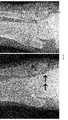
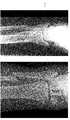
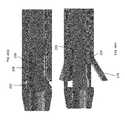
- FIGS. 31A-31Hshow the anatomy of the fibula.
- the fibulais a leg bone located below the knee.
- the fibulais connected to the tibia and is the slenderest of the long bones in the human body.
- the arrowshows the entry point of the device within the patient.
- the distal end 104would extend toward the knee in the intramedullary canal.
- the proximal end 102would be toward the ankle.
- FIGS. 32A-32Jare various method steps to implant the device of FIGS. 1-30 .
- FIGS. 32A-32Jshows the device 100 and the tool 138 , but any of the devices described herein can be inserted using one or more of the following method steps.
- FIG. 32Ashows the assembled tool 138 useful for inserting device 100 (not shown) into bone.
- Hub 158is configured to abut the proximal end 102 of the device 100 .
- Hub 158is coupled to the T-shaped body 140 .
- Device attachment portion 142prevents removal of the hub 158 and the T-shaped body from the device 100 .
- Device attachment portion 142includes a knob 152 that abut the T-shaped body 140 .
- the knob 152 of the device attachment portion 142rigidly couples the hub 158 and the T-shaped body 140 with the device 100 .
- Screwdriver 155can be inserted into the knob 152 of the device attachment portion 142 .
- the assembled tool 138is shown removed from the bone in FIG. 22 .
- FIG. 32Bshows a cross-sectional view of the inserted device 100 .
- the device 100is inserted into the fibula.
- T-shaped body 140can serve as a handle to facilitate insertion of the device 100 .
- knob 152 , knob 154 (not shown) and or screwdriver 155are used to facilitate insertion of the device 100 .
- Distal end 104 of device 100can be inserted into the bone before the proximal end 102 of the device 100 .
- Device 100is inserted into bone segments 2 and 4 .
- Bone segment 2is near the proximal end 102 of the device 100 and bone segment 4 is near the distal end 104 of the device 100 .
- Device 100is in the undeployed state during insertion.
- gripper 108is not actuated by actuator 126 .
- Distal ends 122 of bendable gripping members 118do not contact the inside of the bone to anchor the distal portion 104 of device 100 to the bone.
- Device 100can remain in the undeployed state until the fracture is reduced. The device 100 is inserted into the bone until the device 100 is inserted into both bone segments 2 , 4 and therefore spans the fracture.
- the boneis a fibula.
- Bone segment 2is the distal portion of the fibula and bone segment 4 is a proximal segment of the fibula.
- bone segment 2is the proximal portion of the fibula and bone segment 4 is a distal segment of the fibula.
- the method described hereincan be used with other bones, such as the femur, humerus, tibia, radius, ulna, and clavicle.
- the insertion of the device 100does not align the fracture.
- one fragment of the bonee.g., bone segment 2
- another fragment of the bonee.g., bone segment 204
- Further manipulation of the bone segment 2 and/or the bone segment 204may be necessary.
- the bone segments 2 , 4may be misaligned posteriorly or anteriorly, as those terms are commonly understood anatomically.
- the bone segments 2 , 4may be misaligned distally or proximally, as those terms are commonly understood anatomically.
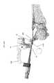
- FIG. 32Cshows the use of K-wires 178 to reduce the fracture.
- K-wires 178can be inserted into bone segment 2 .
- T-shaped body 140includes bores 176 sized to accept K-wires 178 . Bores 176 are also shown in FIG. 21 .
- K-wires 178are inserted through bores 176 and into the bone segment 2 .
- bone segment 2is the distal portion of the fibula.
- the K-wiresmay be inserted into bone segment 4 .
- K-wiresmay be inserted one or more bone segments (bone segment 2 , bone segment 4 , additional bone segments).
- K-wires 178are inserted into bone segment 2 , but any number of K-wires 178 can be used (e.g., one, two, three, four, five, six, etc.). In the illustrated method, K-wires 178 are substantially parallel, but other configures are possible. K-wires 178 may be coaxial, coplanar, parallel, perpendicular, skewed, or any other configuration.
- K-wires 178are positioned on either side of a proximal-distal line.
- K-wires 178pass through the bone segment 2 on either side of the device 100 .
- one or more K-wires 178pass on the anterior side of the device 100 .
- one or more K-wires 178pass on the posterior side of the device 100 . The location and number of K-wires will depend on the nature of the fracture.
- FIG. 32Dshows the insertion of the K-wires 178 into the bone segment 2 . Movement of K-wires 178 can cause movement of bone segment 2 .
- T-shaped body 140can also serve as a handle to facilitate movement of K-wires 178 .
- knob 152is used to facilitate movement of K-wires 178 .
- K-wires 178 and bone segment 2are pulled away from the bone segment 4 to increase the gap between bone segments 2 , 4 .
- K-wires 178 and bone segment 2are pushed toward the bone segment 4 to decrease the gap between bone segments 2 , 4 .
- K-wires 178 and bone segment 2are rotated relative to the bone segment 4 to alter the gap between bone segments 2 , 4 .
- the device 100remains positioned with bone segments 2 , 4 during this motion to align bone segments 2 , 4 .
- FIGS. 32E-32Fshow the fracture is reduced. By manipulating (e.g., pulling, pushing, twisting) the K-wires 178 , the fracture can be manually reduced.
- K-wires 178are driven through the bone segment 2 .
- K-wires 178can be driven into the talus (not shown) to maintain the position of the bone segment 2 .
- K-wires 178can be driven into any stable surface to maintain the position.
- FIG. 32Gshows that in some methods, the gripper 108 is deployed to maintain the position of one or more the bone segments 2 , 4 . In some methods, gripper 108 can be deployed to maintain the position of bone segment 4 . In some methods, the gripper 108 is not deployed until the fracture is reduced by manipulating the K-wires 178 . In some methods, the gripper 108 is deployed prior to manipulating the K-wires 178 . In some methods, the gripper 108 is deployed during manipulation of the K-wires 178 .
- bendable gripping members 118 of gripper 108are urged radially outward by a ramped surface on actuator head 124 .
- Actuator head 124is threaded onto the distal end of actuator 126 .
- screw driver 155turns actuator 126
- a threaded surface of the actuator 126rotates in relation to the actuator head 124 .
- Thiscauses the actuator head 124 to be drawn in a proximal direction toward the proximal end 102 of the device 100 as the actuator head 124 traverses the threaded surface of the actuator 126 .
- the ramped surface on the actuator head 124outwardly actuates gripper members 118 .
- the device 100may include a stop to prevent translation of the actuator 126 .
- FIG. 32Gshows the method of immobilizing both bone segments 2 , 4 .
- Gripper 108prohibits movement of the bone segment 4 .
- K-wires 178prohibit movement of bone segment 2 .
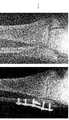
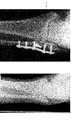
- FIGS. 32H-32Jshow various views of the bone with the device 100 .
- screw 110(not shown) is inserted into aperture 114 of device 100 .
- Screw 110may be guided by removable alignment tube 168 as shown in FIG. 23 .
- Screw 110can be coupled to the bone segment 2 during insertion of screw 110 .
- screw 110will extend transverse to the device 100 .
- one or more K-wires 178remain in place while the screw 110 is inserted.
- Screw 110can be located within the aperture 114 and coupled to the bone segment 2 .
- the bone segments 2 , 4have been previously aligned by manipulating K-wires 178 .
- shaft 162FIG. 26
- shaft 162is translated toward the distal end 104 of the device 100 toward the screw 110 .
- Further translation of shaft 162will push screw 110 and bone segment 2 .
- Further rotation of the rotary driver 132causes the screw 110 to translate within the aperture 114 .
- Screw 110 and bone segment 2can be pushed toward the distal end 104 of the device 100 .
- screw 110functions to approximate the bone fracture.
- K-wires 178translate when the screw 110 is translated.
- T-shaped body 140 and K-wires 178translate when the screw 110 is translated.
- FIGS. 33A-33Gare various method steps to implant the device of FIGS. 1-30 .
- FIGS. 33A-33Gshows the device 100 , but any of the devices described herein can be inserted using one or more of the following method steps.
- FIG. 33Ashows a fibula fracture. Typical fibula fractures result in a compressed and rotated bone fragments. Bone segment 2 is the distal fragment of the fibula and bone segment 4 is the proximal fragment of the fibula. In other methods, bone segment 2 is the proximal fragment of the fibula and bone segment 4 is a distal fragment of the fibula.
- FIG. 33Bshows a Schumann style distractor 180 .
- the Schumann style distractor 180can separate the compressed bone segments 2 , 4 by actuating the handles.
- the Schumann style distractor 180can rotate the bone segments 2 , 4 by deforming the K-wires 178 relative to each other.
- K-wires 178 inserted through the Schumann style distractor 180are position on either side of a proximal-distal line.
- K-wires 178pass through the bone segments 2 , 4 on either side of the device 100 .
- one or more K-wires 178pass on the anterior side of the device 100 .
- one or more K-wires 178pass on the posterior side of the device 100 .
- the location and number of K-wireswill depend on the nature of the fracture.
- FIG. 33Cshows the fracture is reduced by distracting the bone segments 2 , 4 and if necessary rotating the bone segments 2 , 4 relative to each other.
- FIGS. 33D-33Eshows the insertion of a reamer 182 to prepare the bone segments 2 , 4 .
- a reameris a drill.
- a reamer 182is driven through the bone segments 2 , 4 . Strategic placement of the K-wires 178 allows the reamer 182 to pass through the bone segments 2 , 4 without interfering with the K-wires 178 .
- FIG. 33Fshows an embodiment of the reamer 182 .
- the reamer 182has a proximal end and a distal end.
- the distal endcan include at least one spiral cutting edge having a first diameter.
- the proximal endcan include a handle.
- the handlecan be manipulated by a user.
- the handlecan be coupled to a power tool.
- a portion of the shaft of the reamer 182has a diameter less than the first diameter (e.g., an area of reduced diameter).
- the reamer 182includes a through lumen.
- the through lumen of the reamer 182can be inserted over a guiding wire.
- the shank of the reamer 182can have a reduced diameter to increase the flexibility.
- a radiographic depth indicator on the shankindicates when the proper drilling depth is achieved.
- FIG. 33Gshows the implant 100 (not shown) can be inserted with the combination tool 138 while maintaining the reduction with the Schumann style distractor 180 .
- T-shaped body 140can also serve as a handle to facilitate insertion of the device 100 .
- Grippers 108can be deployed (as shown in FIGS. 32G-32I ). Screw 110 may be guided through the device 100 .
- shaft 162FIG. 26
- FIGS. 34A-34Dare various method steps to implant the device of FIGS. 1-30 .
- FIGS. 34A-34Dshows the device 100 , but any of the devices described herein can be inserted using one or more of the following method steps.
- FIG. 34Ashows an alternative style distractor 184 .
- This distractor 184can allow rotation of the bone segment 2 without requiring wire deformation of one or more K-wires 178 .
- FIGS. 34A and 34Cshow a compressed and rotated bone segment 2 .
- Knob 186 of distractor 184can be rotated to rotate the bone segment 2 .
- FIGS. 34A and 34Cshow the bone segment 2 in the original position.
- FIGS. 34B and 34Dshow the bone segment 2 rotated to a new position.
- FIGS. 35A and 35Bare perspective views of an embodiment of a bone fixation device 200 having a proximal end 202 (nearest the surgeon) and a distal end 204 (further from surgeon) and positioned within the bone space of a patient according to the invention.
- the bone fixation device 200can be similar to bone fixation device 100 , and can include any feature or combination of features described herein.
- device 200is configured to be implanted in the fibula, but other configurations for other bony segments are contemplated.
- the proximal end and distal endrefers to the position of an end of the device relative to the remainder of the device or the opposing end as it appears in the drawing.
- the proximal endcan be used to refer to the end manipulated by the user or physician.
- the distal endcan be used to refer to the end of the device that is inserted and advanced within the bone and is furthest away from the physician.
- proximal and distalcould change in another context, e.g. the anatomical context in which proximal and distal use the patient as reference, or where the entry point is distal from the surgeon.
- the deviceWhen implanted within a patient, the device can be held in place with suitable fasteners such as wire, screws, nails, bolts, nuts and/or washers.
- the device 200is used for fixation of fractures of the proximal or distal end of long bones such as intracapsular, intertrochanteric, intercervical, supracondular, or condular fractures of the fibula; for fusion of a joint; or for surgical procedures that involve cutting a bone.
- the devices 200may be implanted or attached through the skin so that a pulling force (traction may be applied to the skeletal system).
- the design of the fixation device 200 depictedis adapted to provide a bone engaging mechanism or gripper 208 adapted to engage target bone of a patient from the inside of the bone.
- the device 200is designed to facilitate bone healing when placed in the intramedullary space within a post fractured bone.
- This device 200has a gripper 208 positioned distally and shown deployed radially outward against the wall of the intramedullary cavity in FIG. 36 . On entry into the cavity, gripper 208 is flat and retracted, as described herein. Upon deployment, gripper 208 pivots radially outward and grips the diaphyseal bone from the inside of the bone.
- FIG. 35Bshows a perspective view of the device 200 in a deployed configuration.
- gripper 208includes opposing bendable gripping members 218 .
- the bendable gripping members 218can be referred to as talons.
- Three bendable gripping members 218are shown in FIG. 36 , but other configurations are contemplated.
- Each bendable gripping member 218is located at the same axial location but offset by 120 degrees.
- Each bendable gripping member 218has a thinned portion 220 that permits bending as the opposite distal end 222 of bendable gripping member 218 is urged radially outward, such that bendable gripping member 218 pivots about thinned portion 220 .
- the device 200has triangular bendable gripping members 218 which are ideal for fixation in the triangular fibula canal.
- the bone canalcan be any shape including circular, non-circular or triangular.
- the gripper 208can have any shape gripping members 218 to correspond with the anatomical canal. In alternative embodiments (not shown), the gripper may comprise 1, 2, 3, 4, 5, 6 or more bendable gripping members similar to bendable gripping members 218 shown.
- FIG. 35Bshows a hemispherical tip cover 234 may be provided at the distal end 204 of the device 200 to act as a blunt obturator. This arrangement facilitates penetration of bone (e.g. an intramedullary space) by device 200 while keeping the tip of device 200 from digging into bone during insertion.
- bonee.g. an intramedullary space
- FIG. 37shows a longitudinal cross-section of device 200 in a deployed configuration.
- the device 200includes an actuator 226 to deploy the device 200 from a un-deployed configuration to the deployed configuration.
- the actuator 226interacts with the bendable gripping members 218 to splay the bendable gripping members 218 outward from the device 200 .
- FIGS. 38A-38Dshow various views of the device 200 .
- the device 200can include a hub 212 comprising one or more aperture 10 , 12 , 14 , 16 , 18 .
- Each aperture 10 , 12 , 14 , 16 , 18has an angle corresponding to the anatomy of the patient. Some apertures accept one type or length of screw. Some apertures accept another type or length of screw.
- One or more screws 20 , 22are placed through apertures 10 , 12 , 14 , 16 , 18 through the hub 212 to lock the device 200 to the bone, as described below. Hence, the metaphysis and the diaphysis are joined.
- the screws 20are distal screws.
- the screws 20have a length between 12 mm and 20 mm.
- the screws 20have a diameter of 2.7 mm.
- the screws 20are locking screws.
- the screws 20engage cortical bone.
- the screws 20are multi-planar.
- the screws 20are locking screws which can resist back-out. Multi-planar screws 20 are stronger in pull out, torsions, tension and compression.
- Two screws 20can have the same orientation.
- Aperture 10 and 14can have the same orientation.
- Apertures 10 and 14can position screws 20 in the lateral-medial directions, as described herein.
- One screws 20can have a different orientation.
- Aperture 12can have a different orientation than apertures 10 and 14 .
- Apertures 12can position screw 20 in the anterior-posterior direction.
- the aperture 12is externally rotated in relation to the transepicondylar axis.
- the aperture 12is rotated anteriorly from the coronal plane.
- the screw 20 through aperture 12is placed obliquely an angle alpha.
- the angle alphais approximately 60 degrees from anteromedial to posterolateral in the transverse plane.
- the aperture 12is oriented 60 degree anteriorly.
- the devicemay comprise a 40 degree, 45 degree, 50 degree, 55 degree, 60 degree, 65 degree, 70 degree, 75 degree, 80 degree, or different anterior angle similar to angle of the aperture 12 shown.
- the aperture 12may form an anterior angle of, for example, approximately 30 degrees, approximately 35 degrees, approximately 40 degrees, approximately 45 degrees, approximately 50 degrees, approximately 55 degrees, approximately 60 degrees, approximately 65 degrees, approximately 70 degrees, approximately 75 degrees, approximately 80 degrees, approximately 85 degrees, approximately 90 degrees etc.
- the aperture 12may form an angle of, for example, between 50-60 degrees, between 55-65 degrees, between 60-70 degrees, between 65-75 degrees, etc.
- the aperture 12may form an angle of, for example, between 40-60 degrees, between 45-65 degrees, between 50-70 degrees, between 55-75 degrees, between 60-80 degrees, between 65-85 degrees etc.
- the aperture 12may form an angle of, for example, between 50-70 degrees, between 45-75 degrees, or between 40-80 degrees, etc.
- the screws 22are syndesmotic screws.
- the screws 22have a length between 40 mm and 70 mm.
- the screws 22have a diameter of 3.5 mm.
- the screws 22are non-locking screws.
- the screws 22engage cortical bone.
- the screws 22are double-lead threads, which rotate twice as fast to engage bone.
- FIG. 38Ashows three screws 20 and two screws 22 , but other configurations are contemplated.
- the devicemay comprise 1, 2, 3, 4, 5, 6 or more screws similar to screw 20 shown.
- the devicemay comprise 1, 2, 3, 4, 5, 6 or more screws similar to screw 22 shown.
- Aperture 16 and 18can have the same orientation. Apertures 16 and 18 can position screws 22 , as described herein.
- the apertures 16 and 18are externally rotated in relation to the transepicondylar axis.
- the apertures 16 and 18are rotated posteriorly from the coronal plane.
- the aperture 12can position the screw 20 in an opposite direction from the coronal plane than the apertures 16 and 18 .
- the screws 22are placed obliquely an angle beta. The angle is approximately 25 degrees from posterolateral to anteromedial in the transverse plane.
- the apertures 16 and 18are oriented 25 degree posteriorly.
- the devicemay comprise 10 degree, 15 degree, 20 degree, 25 degree, 30 degree, 35 degree, 40 degree, 45 degree, 50 degree, or different degree posteriorangle similar to angle of the apertures 16 and 18 shown.
- the apertures 16 and 18may form a posterior angle of, for example, approximately 10 degrees, approximately 15 degrees, approximately 20 degrees, approximately 25 degrees, approximately 30 degrees, approximately 35 degrees, approximately 40 degrees, approximately 45 degrees, approximately 50 degrees, etc.
- the apertures 16 and 18may form a posterior angle of, for example, between 15-25 degrees, between 20-30 degrees, between 25-35 degrees, between 30-40 degrees, etc.
- the apertures 16 and 18may form a posterior angle of, for example, between 5-25 degrees, between 10-30 degrees, between 15-35 degrees, between 20-40 degrees, between 25-45 degrees, or between 30-50 degrees, etc.
- the apertures 16 and 18may form a posterior angle of, for example, between 20-30 degrees, between 15-35 degrees, between 10-40 degrees, or between 5-45 degrees, etc.
- the device 200has a 6 degree bend between the hub 212 and the distal end 204 as shown in FIG. 38B .
- the devicemay comprise 1 degree, 2 degree, 3 degree, 4 degree, 5 degree, 6 degree, 7 degree, 8 degree, 9 degree, 10 degree, 11 degree, 12 degree, 13 degree, 14 degree, 15 degree, or different degree bend similar to bend shown.
- the device 200has a left configuration and a right configuration.
- proximal diameters3 mm, 3.8 mm
- lengths130 mm, 180 mm
- there are many possible configurationse.g., 3 mm ⁇ 130 mm left and right, 3.8 mm ⁇ 130 mm left and right, 3 mm ⁇ 180 mm left and right, 3.8 mm ⁇ 180 mm left and right).
- FIGS. 39A-39Bshow other views of the screws 20 , 22 .
- the apertures 16 and 18are 25 degree anteriorly.
- the aperture 12has a 30 degree orientation from directly anterior.
- FIG. 40illustrates a method of inserting a compression screw 24 into an aperture 10 .
- the compression screw 24can be substantially similar or identical to screw 20 .
- the screw 24can be inserted with a combination tool, described herein.
- the screw 24is aligned with the aperture 10 .
- the screw 24is oriented perpendicular to the longitudinal axis of the hub 212 .
- the aperture 10has at least one dimension greater that the diameter of the screw 24 .
- the at least one dimensioncan be aligned with the longitudinal axis of the hub 212 and/or the longitudinal axis of the device 200 .
- the aperture 10can be generally oblong, elliptical or tear shaped. The shape of the aperture 10 allows the screw 24 to translate within the aperture 8 .
- the screw 24can be inserted into the aperture 10 near the proximal end 202 of the device 200 .
- the screwcan be translated toward the distal end 204 of the device 200 while within the aperture 8 .
- FIG. 40Ashows the screw 24 inserted in the aperture 10 near the proximal end 202 of the device 200 .
- FIG. 40shows the screw 24 translated within the aperture 10 toward the distal end 204 of the device 200 .
- the screw 24translates automatically due to the shape of the aperture 8 . As the screw 24 is rotated, the screw 24 encounters resistance of the aperture 8 . In order to continue to rotate, the screw 24 translates itself within the aperture 10 toward the distal end 204 of the device 200 .
- FIGS. 41A-41Bshow syndesmosis fixation.
- the screws 22are syndesmotic screws, as described herein.
- the screws 22are parallel to the ankle joint.
- the screws 22are anatomically oriented 25 degrees anteriorly.
- the screws 22are anatomically oriented.
- FIG. 42shows the anatomical joint.
- the fibulasits posterior to the tibia.
- the fibulais connected to the tibia by the syndesmosis ligament.
- the syndesmosis ligamentis comprised of the anterior tibiofibular ligament, the posterior tibiofibular ligament and the interosseous membrane.
- the syndesmosis jointis where the fibular incisura notch in the tibia meets the fibular. Referring back to FIGS. 41A-41B , the angle of the screws 22 reduces syndesmotic injury anatomically.
- FIGS. 43A-43Bshows data from a study.
- transsyndesmotic screwsare placed obliquely 30° from posterolateral to anteromedial in the transverse plane.
- Thirty-eight CT scans of the relevant anatomywere used to examine the rotational profile of the axis of the syndesmotic joint in relation to the transepicondylar axis.
- FIG. 43Ashows a line drawn between the femoral epicondyles.
- FIG. 43Bshows the rotation of the syndesmosis 10 mm superior to the ankle joint.
- FIG. 43Cshows syndesmosis rotation superimposed on the transepicondylar axis. The average angle was 32° ⁇ 6°.
- the axis of the distal tibiofibular jointwas 32° ⁇ 6° externally rotated in relation to the transepicondylar axis.
- This studydemonstrates that the axis of the uninjured distal tibiofibular joint is approximately 30° externally rotated in relation to the transepicondylar axis.
- FIGS. 44A-44Sare various method steps to implant the device 200 of FIGS. 35-41B .
- FIGS. 44A-44Sshows the device 200 , but any of the devices described herein can be inserted using one or more of the following method steps.
- FIG. 44Ashows the method step of reducing the fracture.
- the lateral malleolusare reduced percutaneously before reaming.
- a tool 402such as the clamp shown in FIG. 44A is used to reduce the fracture.
- Other commercially available toolscan be utilized to reposition and/or hold the fracture.
- FIG. 44Bshows the method step of establishing an entry point.
- the surgeoncan align the entry point with the long axis of the fibula in the lateral view.
- the surgeoncan aim for the canal center in the anterior/posterior view.
- a K-wire 404is driven across the fracture line.
- a tool 406such as the inserter shown in FIG. 44B and/or the cannula 408 is used to position the K-wire.
- Other commercially available toolscan be utilized to insert a K-wire across the fracture line.
- FIG. 44Cshows the method step of preparing the fibula.
- the surgeoncan drive a tapered reamer 410 over the K-wire 404 .
- the reamer 410can be placed through the cannula 408 .
- the diameter of the reameris 6.2 mm.
- Other commercially available toolscan be utilized to ream the distal portion of the fibula.
- the surgeoncan drive a flexible guide wire 412 through the reamer into the proximal fibula.
- FIG. 44Dshows the inserted guide wire 412 .
- FIG. 44Eshows the method step of preparing the fibula.
- the surgeoncan sequentially ream the proximal fibula.
- the surgeoncan use one or more proximal reamers 414 .
- the proximal reamers 414can be driven over the guide wire 412 .
- the proximal reamer 414can be placed through the cannula 408 .
- the proximal reamer 414can be flexible. Other commercially available tools can be utilized to ream the fibula.
- FIG. 44Fshows the method step of inserting an insertion guide 416 .
- the insertion guide 416can be driven over the guide wire 412 .
- the insertion guide 416has an inner cannula 418 .
- Other commercially available toolscan be utilized to insert the implant.
- FIG. 44Gshows the method step of removing the inner cannula 418 of the insertion guide 416 .
- the guide wire 412is also removed.
- the insertion guide 416can be a portion of a circular cross-section.
- FIG. 44Hshows the method step of inserting the bone fixation device 200 through the insertion guide 416 .
- Other commercially available toolscan be utilized to insert the device 200 .
- the insertion guide 416can support and guide the bone fixation device 200 .
- the insertion guide 416can surround a portion of the bone fixation device 200 during insertion.
- the tool 238can be coupled to the bone fixation device 200 during insertion.
- the tool 238can include apertures aligned with apertures 10 , 12 , 14 , 16 , 18 as described herein.
- FIG. 44Ishows the method step of confirming the depth of insertion of the bone fixation device 200 .
- the stylet 420is inserted through the tool 238 .
- the stylet 420can be inserted toward the proximal end 202 of the bone fixation device 200 .
- the stylet 420can confirm the location of the most proximal edge of the bone fixation device 200 .
- FIG. 44Jshows the method step of actuating the gripper 208 as described herein.
- bendable gripping members 218 of gripper 208are urged radially outward by an actuator 226 (not shown).
- the actuator 226is drawn in a proximal direction toward the proximal end 202 of the bone fixation device 200 .
- the ramped surface on the actuator 226outwardly actuates gripper members 218 .
- Gripper 208is deployed in the bone to lock the position of the bone fixation device 200 .
- FIGS. 44K-44Mshows the methods steps of placing the compression screw 24 as described herein.
- a drill 422is inserted into an aperture in the tool 238 as shown in FIG. 44K .
- the drill 422prepares a pilot hole in the bone and/or through the aperture 10 (see FIG. 44M ).
- the screw 24is inserted into aperture 10 of device 200 (see FIG. 44M ).
- Screw 24may be guided by a tool such as a screwdriver 424 as shown in FIG. 44 L.
- screw 24will extend transverse to the device 200 .
- Screw 24can be located within the aperture 10 and coupled to the bone segment, as shown in FIG. 44M .
- the fracturemay have been previously aligned.
- shaft 262is translated toward the distal end 204 of the device 200 toward the screw 24 . Further translation of shaft 262 will push screw 24 and the bone segment connected to the screw 24 . The screw 24 translates within the aperture 8 . Screw 24 and the attached bone segment can be pushed toward the distal end 204 of the device 200 . As screw 24 is advanced toward the distal end 204 , screw 24 functions to approximate the bone fracture.
- FIG. 44Nshow the methods step of placing the screws 20 , 22 as described herein.
- the tool 238can include apertures 10 ′ 12 ′, 14 ′, 16 ′, 18 ′ aligned with apertures 10 , 12 , 14 , 16 , 18 .
- Screw 20 , 24is inserted within aperture 10 .
- Screw 20is inserted within aperture 12 .
- Screw 20is inserted within aperture 14 .
- Screw 22is inserted within aperture 16 .
- Screw 22is inserted within aperture 18 .
- the screws 20 , 22 , 24can be inserted sequentially.
- One or more screws 20 , 22 , 24can be inserted simultaneously. The surgeon can inserted the screws 20 , 22 in the order best suited for the surgical procedure.
- the surgeoncan insert the screws 22 in either a right orientation or a left orientation depending on the leg being operated on.
- the surgeoncan insert the screw 20 , 24 in aperture 12 in either a right orientation or a left orientation depending on the leg being operated on.
- the screws 20 , 24 in apertures 10 , 14may be universally located for both the right leg and the left leg.
- FIG. 44Oshow the methods step of placing the endcap 228 .
- the endcap 228can prevent encroachment of tissue and/or bone in the lumen of the device 200 .
- the cap 228can be provided to maintain the position of the screw 24 , similar to the endcap 128 shown in FIG. 27 .
- the cap 228can prevent the screw 24 from translating within the aperture 10 toward the proximal end 202 of the device 200 .
- the cap 228can be inserted within the proximal bore of the device 200 until the distal end of the cap abuts the screw 24 .
- the proximal borecan be threaded and the cap 228 can include complementary threads. Other configurations of caps 228 are contemplated.
- FIG. 44Pshows the orientation of the device 200 within the bone. While only one screw 22 is shown, more screws 22 can be positioned within the bone.
- FIGS. 44Q-44Sshow the method step of utilizing other fasteners for securing the syndesmosis.
- FIG. 44Qshows the method step of forming a hole.
- the reamer 426can pass through aperture 16 or 18 of the device.
- the reamercan form a hole through bone aligned with aperture 16 or 18 .
- the diameter of the holeis 3.5 mm.
- FIG. 44Rshows the method step of passing a suture bundle through the hole.
- the suture bundlecan guide the fastener 26 .
- the fastener 26can be similar to commercially available fasteners.
- FIG. 44Sshows the orientation of the device 200 with the fastener 26 . While only one fastener 26 is shown, more fasteners can be positioned within the bone.
- FIG. 45Ashow the reamer 410 .
- the reamer 410 shown in FIG. 45Ais used to perform method step shown in 44 C.
- the reamer 410is tapered.
- the reamer 410can have a central lumen (not shown) to accept a K-wire or flexible guide wire.
- the diameter of the reamer 410is 6.2 mm.
- FIG. 44Bshow the reamer 414 .
- the reamer 414 shown in FIG. 44Bis used to perform method step shown in FIG. 44E .
- the reamer 414can have a central lumen (not shown) to accept a guide wire.
- the proximal reamer 414can be flexible.
- FIGS. 45C-45Dshow the assembled tool 238 useful for inserting device 200 into bone.
- Hub 258is configured to abut the proximal end 202 of the device 200 .
- Hub 258is coupled to the T-shaped body 240 .
- Device attachment portion 242prevents removal of the hub 258 and the T-shaped body from the device 200 .
- Device attachment portion 242includes a knob 252 that abut the T-shaped body 240 .
- the knob 252 of the device attachment portion 242rigidly couples the hub 258 and the T-shaped body 240 with the device 200 .
- the assembled tool 238is shown removed from the bone in FIG. 45C .
- FIG. 45Dshows a view of the inserted device 200 .
- the device 200is inserted into the fibula.
- T-shaped body 240can serve as a handle to facilitate insertion of the device 200 .
- Distal end 204 of device 200can be inserted into the bone before the proximal end 202 of the device 200 .
- Device 200is in the un-deployed state during insertion as shown in FIG. 45C .
- gripper 208is not actuated by actuator 226 .
- Distal ends 222 of bendable gripping members 218do not contact the inside of the bone to anchor the distal portion 204 of device 200 to the bone.
- Device 200can remain in the un-deployed state until the fracture is reduced.
- FIG. 45Dshows that in some methods, the gripper 208 is deployed to maintain the position of one or more the bone segments. Typical fibula fractures result in a compressed and rotated bone fragments.
- FIG. 45Dshows the implant 200 can be inserted with the combination tool 138 .
- T-shaped body 240can also serve as a handle to facilitate insertion of the device 200 .
- Grippers 208can be deployed (as shown in FIG. 45D ). Screws 20 may be guided through the device 200 . Screws 22 may be guided through the device 200 .
- FIGS. 45E-45Hshow an embodiment of the actuator 226 .
- bendable gripping members 218 of gripper 208are urged radially outward by a ramped surface on actuator head 224 .
- Actuator head 224is threaded onto the distal end of actuator 226 .
- the proximal end of actuator 226has a keyed socket 230 for receiving the tip of the tip of a screw driver through the proximal bore of device 200 .
- the keyed socket 230is hex shaped. As screw driver turns actuator 226 , a threaded surface of the actuator 226 rotates in relation to the actuator head 224 .
- the actuator head 224This causes the actuator head 224 to be drawn in a proximal direction toward the proximal end 202 of the device 200 as the actuator head 224 traverses the threaded surface of the actuator 226 .
- the ramped surface on the actuator head 224outwardly actuates bendable gripping members 218 .
- the device 200may include a stop to prevent translation of the actuator 226 .
- the actuator 226may include one or more bends to match the shape of the device 200 .
- the actuator 226may be flexible or have a flexible portion between the keyed socket 230 and the threaded surface.
- FIGS. 45I-45Jshow a perspective view of an embodiment of a screw driver 320 .
- the screw driver 320may be configured to engage the keyed socket 130 of the actuator 126 (shown in FIG. 14 ) or the keyed socket 230 of the actuator 226 (shown in FIG. 45E ).
- the screw driver 320may be configured to engage the keyed socket 148 of the screw 110 (shown in FIG. 16A ).
- the screw driver 320includes a proximal end 322 and a distal end 324 .
- the proximal end 322can have a mating configuration such as a flattened surface.
- the mating surfacecan engage a knob to facilitate rotation.
- the mating surfacecan engage a power source such a drill.
- the mating configurationcan be a hand grip.
- the screw driver 320can be sized and shaped to fit within the proximal bore of the device 200 .
- the screw driver 320can be sized and shaped to fit within the alignment tube 168 , 268 , as described herein.
- FIG. 45Jshows the distal end 324 .
- the distal end 324includes a hex tip 326 .
- All the flats 328are sized to fit a female hex of the corresponding keyed socket 130 , 148 , 230 .
- each flat 328is 2.5 mm but other sizes are contemplated.
- the hex tip 326includes a slot 330 across one pair of flats 328 .
- the slot 330bisects the pair of flats 328 .
- the slot 330does not extend beyond the hex tip 326 .
- the depth and width of the slot 330depends on the retaining force with the actuator 126 , 226 or with the screw 110 .
- the slotcan extend about 0.020′′ into the distal end 324 .
- the hex tip 326is machined with a lip 332 .
- the hex tipis manufactures such that the hex surface is larger than the corresponding socket.
- the lip 332creates an interference between the screw driver 320 and the keyed socket 130 , 148 , 230 .
- the interferenceis on the order of 0.0002′′ ⁇ 0.001′′ (e.g., 0.0002′′, 0003′′, 0.0004′′, 0.0005′′, 0.0006′′, 0.0007′′, 0.0008′′, 0.0009′′, 0.001′′, between 0.002′′ and 0.005′′, etc.).
- the material of the screw driver 320is selected maintain the shape of the lip 322 .
- One suitable materialis heat treated stainless steel.
- the configuration of the screw driver 320prevents stripping of the keyed socket 130 , 148 , 230 . In some embodiments (not shown), an elastomer could be inserted into the slot 330 to provide additional spring back if needed.
- FIGS. 45K-45Lshow views of the combination tool 238 useful for inserting device 200 , actuating gripper 208 , approximating the fracture in bone, aligning one or more anchor screw(s) 20 , 22 , 24 , and/or removing device 200 , if desired.
- the main components of tool 238are the hub 258 , the T-shaped body 240 , the device attachment portion 242 , and the alignment tube 268 .
- the alignment tube 268is shown in FIG. 45K .
- the alignment tube 268can be coupled to the T-shaped body 240 .
- the combination tool 238is in place when the device attachment portion 242 rigidly couples the hub 258 and the T-shaped body 240 to the device 200 .
- the removable alignment tube 268aligns with the aperture 18 of the device 200 .
- the T-shaped body 140includes a plurality of apertures including aperture 18 ′.
- alignment tube 268is first received in aperture 18 ′. In this position, alignment tube 268 is in axial alignment with aperture 18 of device 200 .
- the mating configuration of device 200 and hub 258positions aperture 18 in its desired orientation.
- a drill bit, screw driver 270 , screw 22 and/or other fastening device or toolmay be inserted through the bore of alignment tube 268 such that the device(s) are properly aligned with aperture 18 .
- screw 22is shown, the alignment tube 268 can be used with screw 20 , 24 in the same manner.
- the outward end of alignment tube 268may also serve as a depth guide to stop a drill bit, screw 22 and/or other fastener from penetrating bone beyond a predetermined depth.
- the alignment tube 268allows proper placement of the screw 22 even if the aperture 18 or other portions of the device 200 are obstructed from the view of the surgeon.
- the T-shaped body 240includes other apertures 10 ′, 12 ′, 14 ′, 16 ′ that align with apertures 10 , 12 , 14 , 16 , as described herein.
- Alignment tube 268may be withdrawn from aperture 18 ′ as shown, and inserted in another aperture 10 ′, 12 ′, 14 ′, 16 .
- the alignment tube 268can be inserted within these apertures to align and insert other screws 20 , 22 .
- the alignment tube 268is removed in FIG. 45L .
- the screwdriver 270is shown coupled to the end of the screw 22 .
- the screwdriver 270can be used to drive in other screw 20 , 24 (not shown).
- a screw clip 272surrounds a portion of the screwdriver 270 and a portion of the screw 22 .
- the screw clip 272can be used with screw 20 , in the same manner as screw 22 .
- the coupled combination of the screwdriver 270 , the screw 22 , and the screw clip 272can be inserted into the alignment tube 268 and moved toward the fibula.
- the screwdriver 270can rotate within the screw clip 272 to drive the screw 22 into the bone.
- FIG. 45Mshows the screw clip 272 and the screw 22 .
- the screw clip 272can include one or more markings 274 .
- the markings 274can indicate the proper orientation of the screw 22 into the screw clip 272 .
- the screw clip 272has a proximal edge 276 which is tapered. The proximal edge 276 interacts with the head of the screw 22 . As the screw 22 is driven into the bone, the head of the screw 22 tilts the screw clip 272 away from the bone. The screw 22 can be removed from the screw clip 272 through enlarged slot 278 .
- FIG. 45Nshows the screw clip 272 , the screw 22 , and the device 200 .
- the tool 238ensure proper placement of the screw 22 through the aperture 18 in the device 200 .
- FIG. 45Oshows the screw clip 272 and the screw 22 .
- the head of the screw 22tilts the screw clip 272 downward as shown by the arrow.
- the head of the screw 22slides along the proximal edge 276 toward the top surface of the screw clip 22 .
- the screw clip 272falls away as the screw 22 passes through enlarged slot 278 .
- the inventive implantable device, tools and methodsmay be used in many locations within the body.
- the proximal end of a device in the anatomical contextis the end closest to the body midline and the distal end in the anatomical context is the end further from the body midline, for example, on the humerus, at the head of the humerus (located proximal, or nearest the midline of the body) or at the lateral or medial epicondyle (located distal, or furthest away from the midline); on the radius, at the head of the radius (proximal) or the radial styloid process (distal); on the ulna, at the head of the ulna (proximal) or the ulnar styloid process (distal); for the femur, at the greater trochanter (proximal) or the lateral epicondyle or medial epicondyle (distal); for the tibia, at the medial
- access locationsother than the ones described herein may also be suitable depending upon the location and nature of the fracture and the repair to be achieved.
- the devices taught hereinare not limited to use on the long bones listed above, but can also be used in other areas of the body as well, without departing from the scope of the invention. It is within the scope of the invention to adapt the device for use in flat bones as well as long bones.
Landscapes
- Health & Medical Sciences (AREA)
- Orthopedic Medicine & Surgery (AREA)
- Surgery (AREA)
- Life Sciences & Earth Sciences (AREA)
- Heart & Thoracic Surgery (AREA)
- Veterinary Medicine (AREA)
- Engineering & Computer Science (AREA)
- Biomedical Technology (AREA)
- Nuclear Medicine, Radiotherapy & Molecular Imaging (AREA)
- Medical Informatics (AREA)
- Molecular Biology (AREA)
- Animal Behavior & Ethology (AREA)
- General Health & Medical Sciences (AREA)
- Public Health (AREA)
- Neurology (AREA)
- Dentistry (AREA)
- Oral & Maxillofacial Surgery (AREA)
- Surgical Instruments (AREA)
Abstract
Description
Claims (16)
Priority Applications (2)
| Application Number | Priority Date | Filing Date | Title |
|---|---|---|---|
| US14/861,355US9814499B2 (en) | 2014-09-30 | 2015-09-22 | Intramedullary fracture fixation devices and methods |
| US15/805,798US10548648B2 (en) | 2014-09-30 | 2017-11-07 | Intramedullary fracture fixation devices and methods |
Applications Claiming Priority (2)
| Application Number | Priority Date | Filing Date | Title |
|---|---|---|---|
| US201462057913P | 2014-09-30 | 2014-09-30 | |
| US14/861,355US9814499B2 (en) | 2014-09-30 | 2015-09-22 | Intramedullary fracture fixation devices and methods |
Related Child Applications (1)
| Application Number | Title | Priority Date | Filing Date |
|---|---|---|---|
| US15/805,798DivisionUS10548648B2 (en) | 2014-09-30 | 2017-11-07 | Intramedullary fracture fixation devices and methods |
Publications (2)
| Publication Number | Publication Date |
|---|---|
| US20160089189A1 US20160089189A1 (en) | 2016-03-31 |
| US9814499B2true US9814499B2 (en) | 2017-11-14 |
Family
ID=54256537
Family Applications (2)
| Application Number | Title | Priority Date | Filing Date |
|---|---|---|---|
| US14/861,355Active2036-01-19US9814499B2 (en) | 2014-09-30 | 2015-09-22 | Intramedullary fracture fixation devices and methods |
| US15/805,798Active2035-12-05US10548648B2 (en) | 2014-09-30 | 2017-11-07 | Intramedullary fracture fixation devices and methods |
Family Applications After (1)
| Application Number | Title | Priority Date | Filing Date |
|---|---|---|---|
| US15/805,798Active2035-12-05US10548648B2 (en) | 2014-09-30 | 2017-11-07 | Intramedullary fracture fixation devices and methods |
Country Status (2)
| Country | Link |
|---|---|
| US (2) | US9814499B2 (en) |
| EP (1) | EP3001960B1 (en) |
Cited By (25)
| Publication number | Priority date | Publication date | Assignee | Title |
|---|---|---|---|---|
| US20170202566A1 (en)* | 2014-07-15 | 2017-07-20 | Ot Medizintechnik Gmbh | Positioning device for securing an intramedullary nail in a long bone |
| US20180085151A1 (en)* | 2015-04-16 | 2018-03-29 | Texas Tech University System | Ankle (Tibio-Talar) Fusion Nail |
| US9931219B2 (en) | 2014-03-07 | 2018-04-03 | Arthrosurface Incorporated | Implant and anchor assembly |
| US9931211B2 (en) | 2003-02-24 | 2018-04-03 | Arthrosurface Incorporated | Trochlear resurfacing system and method |
| US20180092674A1 (en)* | 2016-10-05 | 2018-04-05 | Arthrex, Inc. | Fifth metatarsal repair systems and methods of use |
| US10045788B2 (en) | 2006-12-11 | 2018-08-14 | Arthrosurface Incorporated | Retrograde resection apparatus and method |
| US10076343B2 (en) | 2002-12-03 | 2018-09-18 | Arthrosurface Incorporated | System for articular surface replacement |
| US10307172B2 (en) | 2012-07-03 | 2019-06-04 | Arthrosurface Incorporated | System and method for joint resurfacing and repair |
| US10478200B2 (en) | 2009-04-17 | 2019-11-19 | Arthrosurface Incorporated | Glenoid resurfacing system and method |
| US10610270B2 (en) | 2018-01-15 | 2020-04-07 | Glw, Inc. | Hybrid intramedullary rods |
| US10624752B2 (en) | 2006-07-17 | 2020-04-21 | Arthrosurface Incorporated | Tibial resurfacing system and method |
| US10624748B2 (en) | 2014-03-07 | 2020-04-21 | Arthrosurface Incorporated | System and method for repairing articular surfaces |
| US10695096B2 (en) | 2013-04-16 | 2020-06-30 | Arthrosurface Incorporated | Suture system and method |
| US10945743B2 (en) | 2009-04-17 | 2021-03-16 | Arthrosurface Incorporated | Glenoid repair system and methods of use thereof |
| US11160663B2 (en) | 2017-08-04 | 2021-11-02 | Arthrosurface Incorporated | Multicomponent articular surface implant |
| US20210346067A1 (en)* | 2015-12-28 | 2021-11-11 | Glenhurst Labs, Llc | Surgical devices for small bone fracture surgery |
| US11197699B2 (en) | 2015-05-22 | 2021-12-14 | Stryker European Operations Holdings Llc | Implant system for bone fixation |
| US20220071677A1 (en)* | 2020-09-04 | 2022-03-10 | DePuy Synthes Products, Inc. | Temporary Antimicrobial Cement Spacer, Assembly, Kit, And Method Of Manufacture |
| US20220151664A1 (en)* | 2015-04-16 | 2022-05-19 | Texas Tech University System | Ankle (Tibio-Talar) Fusion Nail |
| US11432855B2 (en) | 2018-12-19 | 2022-09-06 | Gregory Haig Dadourian | Compressive intramedullary rod |
| US11478358B2 (en) | 2019-03-12 | 2022-10-25 | Arthrosurface Incorporated | Humeral and glenoid articular surface implant systems and methods |
| US11607319B2 (en) | 2014-03-07 | 2023-03-21 | Arthrosurface Incorporated | System and method for repairing articular surfaces |
| US11712276B2 (en) | 2011-12-22 | 2023-08-01 | Arthrosurface Incorporated | System and method for bone fixation |
| US12064156B2 (en) | 2023-01-09 | 2024-08-20 | John F. Krumme | Dynamic compression fixation devices |
| US12232790B2 (en) | 2022-12-30 | 2025-02-25 | IvyTech Design LLC | Adjustable angle orthopedic distractor, compressor, and distractor-compressor |
Families Citing this family (20)
| Publication number | Priority date | Publication date | Assignee | Title |
|---|---|---|---|---|
| US9770278B2 (en) | 2014-01-17 | 2017-09-26 | Arthrex, Inc. | Dual tip guide wire |
| WO2017103658A1 (en)* | 2015-12-17 | 2017-06-22 | Stryker European Holdings I, Llc | Expandable bone nail |
| US11013506B2 (en) | 2017-11-01 | 2021-05-25 | Wright Medical Technology, Inc. | Partially assembled knotless suture construct |
| CN106175899A (en)* | 2016-06-29 | 2016-12-07 | 江苏艾迪尔医疗科技股份有限公司 | Fibula intramedullary pin |
| JP6811498B2 (en) | 2016-09-08 | 2021-01-13 | メダロック, エルエルシー | Implants and methods for long bone fixation |
| US10751096B2 (en) | 2016-09-22 | 2020-08-25 | Bala Sundararajan | Systems and methods for intramedullary nail implantation |
| US10492803B2 (en) | 2016-09-22 | 2019-12-03 | Globus Medical, Inc. | Systems and methods for intramedullary nail implantation |
| US11045242B2 (en) | 2016-09-22 | 2021-06-29 | Globus Medical, Inc. | Systems and methods for intramedullary nail implantation |
| US10299847B2 (en) | 2016-09-22 | 2019-05-28 | Globus Medical, Inc. | Systems and methods for intramedullary nail implantation |
| US11083503B2 (en) | 2016-09-22 | 2021-08-10 | Globus Medical, Inc. | Systems and methods for intramedullary nail implantation |
| TR201704262A2 (en)* | 2017-03-21 | 2018-09-21 | Kayahan Karaytug | Fibula Distal Intamedullary Nails |
| US11051799B2 (en) | 2017-09-01 | 2021-07-06 | Wright Medical Technology, Inc. | Augmented suture construct for syndesmotic stabilization |
| WO2019168817A1 (en)* | 2018-02-27 | 2019-09-06 | The University Of Toledo | Syndesmosis fixation and reconstruction system and method of using the same |
| EP3626184A1 (en)* | 2018-09-21 | 2020-03-25 | OrthoXel DAC | A femoral nail system |
| US11633219B2 (en) | 2019-06-26 | 2023-04-25 | Globus Medical, Inc. | Fenestrated pedicle nail |
| WO2021211829A1 (en)* | 2020-04-15 | 2021-10-21 | Auston Darryl | Improved linear fibular nail |
| CN112472264A (en)* | 2020-12-11 | 2021-03-12 | 阳江市人民医院 | Clavicle intramedullary nail and nail implanting method |
| EP4312838A1 (en)* | 2021-06-22 | 2024-02-07 | Smith & Nephew, Inc. | Self-countersinking bone fastener and method for countersinking a bone fastener used in connection with an orthopedic implant |
| US12064150B2 (en)* | 2022-01-19 | 2024-08-20 | Globus Medical Inc. | System and method for treating bone fractures |
| WO2025155842A1 (en)* | 2024-01-19 | 2025-07-24 | Paragon 28, Inc. | Fibular nail system, instrumentation, and surgical methods |
Citations (656)
| Publication number | Priority date | Publication date | Assignee | Title |
|---|---|---|---|---|
| US958127A (en) | 1909-11-04 | 1910-05-17 | Knut T Hovrud | Pole-anchor. |
| US1169635A (en) | 1915-07-07 | 1916-01-25 | Lester A Grimes | Pipe-hanger. |
| US1790841A (en) | 1931-02-03 | Expansion bolt | ||
| US2502267A (en) | 1946-03-13 | 1950-03-28 | Robert L Mcpherson | Self-clinching fastener |
| US2685877A (en) | 1952-03-20 | 1954-08-10 | Dobelle Martin | Femoral head prosthesis |
| US2998007A (en) | 1955-02-19 | 1961-08-29 | Herzog Kurt | Internal tubular splint for the fixation of bone fractures and method of applying it |
| US3118444A (en) | 1961-11-20 | 1964-01-21 | Jr Jose C Serrato | Forearm rod for fractures |
| US3441017A (en) | 1965-03-24 | 1969-04-29 | Hans Jurgen Kaessmann | Apparatus for the treatment of fractures of tubular bones |
| US3626935A (en) | 1969-08-12 | 1971-12-14 | Gen Motors Corp | Surgical nail extractor |
| US3710789A (en) | 1970-12-04 | 1973-01-16 | Univ Minnesota | Method of repairing bone fractures with expanded metal |
| US3759257A (en) | 1971-03-13 | 1973-09-18 | Fischer Artur | Connector for fractured tubular bones |
| US3760802A (en) | 1971-02-26 | 1973-09-25 | Fischer Artur | Supporting device for fractured tubular bones |
| US3779239A (en) | 1971-03-13 | 1973-12-18 | Fischer Artur | Connector for fractured bones |
| US3791380A (en) | 1971-12-13 | 1974-02-12 | G Dawidowski | Method and apparatus of immobilizing a fractured femur |
| US3846846A (en) | 1972-09-28 | 1974-11-12 | Fischer Artur | Hip joint prosthesis |
| US3955565A (en) | 1973-12-05 | 1976-05-11 | Johnson Jr Glenn W | Orthopedic apparatus |
| US3978528A (en) | 1975-06-26 | 1976-09-07 | Howmedica, Inc. | Bone and joint prosthesis |
| US3986504A (en) | 1974-10-25 | 1976-10-19 | Rafael Pares Avila | Internal fixation device for securing two fractured bone joints together |
| US4007528A (en) | 1975-10-22 | 1977-02-15 | Shea John J | High speed bone drill |
| US4011602A (en) | 1975-10-06 | 1977-03-15 | Battelle Memorial Institute | Porous expandable device for attachment to bone tissue |
| US4016874A (en) | 1976-05-19 | 1977-04-12 | Maffei Ernest J | Three-part intramedullary bone-setting pin |
| US4050646A (en) | 1975-12-05 | 1977-09-27 | Burchette Jr Robert L | Yarn carrier |
| US4064567A (en) | 1976-09-15 | 1977-12-27 | The Sampson Corporation | Prosthesis-to-bone interface system |
| US4065816A (en) | 1975-05-22 | 1978-01-03 | Philip Nicholas Sawyer | Surgical method of using a sterile packaged prosthesis |
| US4091806A (en) | 1976-01-13 | 1978-05-30 | Jacob Aginsky | Intramedullary compression nail for the treatment of bone fractures |
| US4146022A (en) | 1977-11-16 | 1979-03-27 | Ronald A. Johnson | Fracture fixation by cerclage utilizing cortical bone tack and pull-out tension device |
| US4164794A (en) | 1977-04-14 | 1979-08-21 | Union Carbide Corporation | Prosthetic devices having coatings of selected porous bioengineering thermoplastics |
| US4190044A (en) | 1978-08-16 | 1980-02-26 | Wood Eugene W | Telescoping intermedullary pin |
| USD255048S (en) | 1977-10-17 | 1980-05-20 | Howmedica, Inc. | Intramedullary brush |
| US4204531A (en) | 1977-12-28 | 1980-05-27 | Yacov Aginsky | Intramedullary nail with expanding mechanism |
| US4227518A (en) | 1978-02-12 | 1980-10-14 | Jacob Aginsky | Intramedullary retraction nail for fixation of comminuted fractured bones |
| US4236512A (en) | 1978-02-12 | 1980-12-02 | Jacob Aginsky | Connector for fractured bones |
| US4237875A (en) | 1979-02-23 | 1980-12-09 | Towmotor Corporation | Dynamic intramedullary compression nailing |
| US4246662A (en) | 1979-06-07 | 1981-01-27 | Zimmer Usa, Inc. | Prosthetic joint |
| US4262665A (en) | 1979-06-27 | 1981-04-21 | Roalstad W L | Intramedullary compression device |
| US4275717A (en) | 1979-07-27 | 1981-06-30 | Zimmer Usa, Inc. | Intramedullary fixation device for fractured tubular bones |
| US4293962A (en) | 1980-02-14 | 1981-10-13 | Zimmer Usa, Inc. | Bone plug inserting system |
| US4294251A (en) | 1978-10-17 | 1981-10-13 | Greenwald A Seth | Method of suction lavage |
| US4312336A (en) | 1978-11-10 | 1982-01-26 | Orthofix S.R.1. | External axial fixation unit |
| US4313434A (en) | 1980-10-17 | 1982-02-02 | David Segal | Fracture fixation |
| US4338926A (en) | 1980-11-21 | 1982-07-13 | Howmedica, Inc. | Bone fracture prosthesis with controlled stiffness |
| US4351069A (en) | 1979-06-29 | 1982-09-28 | Union Carbide Corporation | Prosthetic devices having sintered thermoplastic coatings with a porosity gradient |
| US4352212A (en) | 1979-03-05 | 1982-10-05 | Howmedica, Inc. | Joint prosthesis |
| US4353358A (en) | 1980-08-28 | 1982-10-12 | Emerson Reynolds L | Sigmoidoscope |
| US4379451A (en) | 1980-11-04 | 1983-04-12 | Getscher Philip E | Intramedullary hip pin and cortical plate |
| US4409974A (en) | 1981-06-29 | 1983-10-18 | Freedland Jeffrey A | Bone-fixating surgical implant device |
| US4453539A (en) | 1982-03-01 | 1984-06-12 | The University Of Toledo | Expandable intramedullary nail for the fixation of bone fractures |
| US4457301A (en) | 1982-06-18 | 1984-07-03 | Howmedica Inc. | Intramedullary fixation device |
| US4459708A (en) | 1979-07-10 | 1984-07-17 | Bernard Buttazzoni | Joint prosthesis |
| US4462394A (en) | 1982-05-03 | 1984-07-31 | Howmedica, Inc. | Intramedullary canal seal for cement pressurization |
| US4467794A (en) | 1982-02-08 | 1984-08-28 | Ernest Maffei | Intramedulary bone-setting assembly |
| US4492226A (en) | 1979-10-10 | 1985-01-08 | Vsesojuzny Nauchno-Issledovatelsky I Ispytatelny Institut Meditsinskoi Tekhniki | Device for uniting bone fragments |
| US4503847A (en) | 1982-01-15 | 1985-03-12 | Howmedica, Inc. | Prosthetic nail |
| US4519100A (en) | 1982-09-30 | 1985-05-28 | Orthopedic Equipment Co. Inc. | Distal locking intramedullary nail |
| US4520511A (en) | 1981-10-26 | 1985-06-04 | Paribelli Gianezio | Hip prosthesis with expanding femoral component |
| US4522200A (en) | 1983-06-10 | 1985-06-11 | Ace Orthopedic Company | Adjustable intramedullar rod |
| US4541423A (en) | 1983-01-17 | 1985-09-17 | Barber Forest C | Drilling a curved hole |
| US4552136A (en) | 1983-10-19 | 1985-11-12 | Howmedica, Inc. | Femoral rasp |
| US4589883A (en) | 1983-06-06 | 1986-05-20 | Pfizer Hospital Products Group, Inc. | Femoral hip prosthesis |
| US4590930A (en) | 1983-06-22 | 1986-05-27 | Lloyd A. Kurth | Fixation device and process for an intramedullary nail |
| US4604997A (en) | 1984-02-13 | 1986-08-12 | Orthofix S.R.L. | Articulated mini external fixation device |
| US4621627A (en) | 1984-12-18 | 1986-11-11 | Orthofix S.R.L. | External axial fixation device |
| US4622959A (en) | 1985-03-05 | 1986-11-18 | Marcus Randall E | Multi-use femoral intramedullary nail |
| US4624673A (en) | 1982-01-21 | 1986-11-25 | United States Medical Corporation | Device system for dental prosthesis fixation to bone |
| US4628920A (en) | 1983-12-12 | 1986-12-16 | Synthes Ltd. | Intramedullary nail |
| US4632101A (en) | 1985-01-31 | 1986-12-30 | Yosef Freedland | Orthopedic fastener |
| US4643177A (en) | 1984-06-13 | 1987-02-17 | University Of Florida | Dynamic traction wrist cast brace |
| US4651724A (en) | 1984-05-18 | 1987-03-24 | Technomed Gmk | Bone joining plate |
| US4653487A (en) | 1986-01-29 | 1987-03-31 | Maale Gerhard E | Intramedullary rod assembly for cement injection system |
| US4662887A (en) | 1984-06-15 | 1987-05-05 | Imperial Chemical Industries | Prosthetic devices |
| US4667663A (en) | 1983-07-13 | 1987-05-26 | Keizo Miyata | Intramedullary nail used to unite separated fragments of fractured long bone |
| USD290399S (en) | 1985-03-04 | 1987-06-16 | Zimmer, Inc. | Combined driver and extractor for intramedullary pins or the like |
| US4681590A (en) | 1986-06-18 | 1987-07-21 | John Tansey | Femoral stem prosthesis |
| US4697585A (en) | 1985-01-11 | 1987-10-06 | Williams Michael O | Appliance for fixing fractures of the femur |
| US4705027A (en) | 1984-05-14 | 1987-11-10 | Synthes Ltd. (U.S.A.) | Intramedullary nail |
| US4705032A (en) | 1983-08-19 | 1987-11-10 | Waldemar Link Gmbh & Co. | Anchoring rod for tubular bones |
| US4721103A (en) | 1985-01-31 | 1988-01-26 | Yosef Freedland | Orthopedic device |
| US4735625A (en) | 1985-09-11 | 1988-04-05 | Richards Medical Company | Bone cement reinforcement and method |
| US4753657A (en) | 1984-01-16 | 1988-06-28 | University Of Exeter | Fixation of implants in bone |
| US4776330A (en) | 1986-06-23 | 1988-10-11 | Pfizer Hospital Products Group, Inc. | Modular femoral fixation system |
| US4781181A (en) | 1985-08-27 | 1988-11-01 | Zimmer, S.A. | Boring sensor for intramedullary nail and corresponding intramedullary nail |
| US4805595A (en) | 1987-04-28 | 1989-02-21 | Olympus Optical Co., Ltd. | Flexible tube assembly for endoscope |
| US4805607A (en) | 1987-12-03 | 1989-02-21 | Boehringer Mannheim Corporation | Modular intramedullary nail system |
| US4813963A (en) | 1987-08-24 | 1989-03-21 | Zimmer, Inc. | Femoral component for a hip prosthesis |
| US4827919A (en) | 1986-10-27 | 1989-05-09 | Pfizer Hospital Products Group, Inc. | Femoral spacer |
| US4828277A (en) | 1986-09-30 | 1989-05-09 | Orthofix S.R.L. | Self-gradually locking chuck |
| US4854312A (en) | 1988-04-13 | 1989-08-08 | The University Of Toledo | Expanding intramedullary nail |
| US4858602A (en) | 1985-12-06 | 1989-08-22 | Howmedica GmbH Werk Schonkirchen | Bone nail for the treatment of upper arm fractures |
| US4862883A (en) | 1988-04-21 | 1989-09-05 | Yosef Freeland | Interlocking intramedullary nail |
| US4871369A (en) | 1987-11-23 | 1989-10-03 | Pfizer Hospital Products Group, Inc. | Long stem hip implant |
| US4875475A (en) | 1984-11-30 | 1989-10-24 | Synthes (U.S.A.) | Device for treating a bone |
| US4875474A (en) | 1988-01-29 | 1989-10-24 | Biomet, Inc. | Variable wall thickness interlocking intramedullary nail |
| US4896662A (en) | 1987-11-30 | 1990-01-30 | Pfizer Hospital Products Group, Inc. | Sealing device for introducing cement into a bone canal |
| US4921499A (en) | 1987-10-05 | 1990-05-01 | Ordev B.V. | Adjustable prosthesis |
| US4927424A (en) | 1988-07-26 | 1990-05-22 | Mcconnell Bernard E | Reamer guide for intramedullary nail placement |
| US4932969A (en) | 1987-01-08 | 1990-06-12 | Sulzer Brothers Limited | Joint endoprosthesis |
| US4943291A (en) | 1987-12-18 | 1990-07-24 | Zimmer S.A. | Drilling feeler, in particular for positioning and securing a medullary nail |
| US4959066A (en) | 1989-02-24 | 1990-09-25 | Zimmer, Inc. | Femoral osteotomy guide assembly |
| US4969889A (en) | 1986-12-22 | 1990-11-13 | Zimmer, Inc. | Instrument for locating a hole |
| US4976258A (en) | 1983-03-09 | 1990-12-11 | Howmedica International, Inc. | Locking nail |
| US4978358A (en) | 1988-10-06 | 1990-12-18 | Zimmer Inc. | Orthopaedic prosthetic device possessing improved composite stem design |
| US4978349A (en) | 1989-08-03 | 1990-12-18 | Synthes (U.S.A.) | Fixation plate |
| US4988349A (en) | 1987-01-21 | 1991-01-29 | Orthofix S.R.L. | Device for osteosynthesis |
| US5002580A (en) | 1988-10-07 | 1991-03-26 | Pfizer Hospital Products Group, Inc. | Prosthetic device and method of implantation |
| US5002547A (en) | 1987-02-07 | 1991-03-26 | Pfizer Hospital Products Group, Inc. | Apparatus for knee prosthesis |
| US5006120A (en) | 1989-10-10 | 1991-04-09 | Carter Peter R | Distal radial fracture set and method for repairing distal radial fractures |
| US5013314A (en) | 1985-11-05 | 1991-05-07 | Intreprinderea Industria Tehnico-Medicala | Instrumentation and method for inserting flexible implants into fractured bones |
| US5019077A (en) | 1989-03-17 | 1991-05-28 | Orthofix S.R.L. | External splint |
| US5026374A (en) | 1989-05-12 | 1991-06-25 | Orthofix S.R.L. | Bolt for orthopaedic surgical use |
| US5027799A (en) | 1988-04-19 | 1991-07-02 | Lincoln Mills, Inc. | Limb supporting device for arthroscopic surgery |
| US5030222A (en) | 1990-05-09 | 1991-07-09 | James Calandruccio | Radiolucent orthopedic chuck |
| US5034013A (en) | 1989-04-24 | 1991-07-23 | Zimmer Inc. | Intramedullary nail |
| US5034012A (en) | 1989-11-21 | 1991-07-23 | Synthes (U.S.A.) | Intramedullary nail with loop tip |
| US5035697A (en) | 1990-03-20 | 1991-07-30 | Synthes (U.S.A.) | Orthopedic medullary nail |
| US5037423A (en) | 1983-10-26 | 1991-08-06 | Pfizer Hospital Products Group, Inc. | Method and instrumentation for the replacement of a knee prosthesis |
| US5041115A (en) | 1988-03-14 | 1991-08-20 | Synthes (U.S.A.) | Medullary nail for the tibia |
| US5053035A (en) | 1990-05-24 | 1991-10-01 | Mclaren Alexander C | Flexible intramedullary fixation rod |
| US5057103A (en) | 1990-05-01 | 1991-10-15 | Davis Emsley A | Compressive intramedullary nail |
| US5062854A (en) | 1988-10-07 | 1991-11-05 | Pfizer Hospital Products Group | Prosthetic device and method of implantation |
| US5066296A (en) | 1989-02-02 | 1991-11-19 | Pfizer Hopsital Products Group, Inc. | Apparatus for treating a fracture |
| US5084050A (en) | 1984-12-14 | 1992-01-28 | Klaus Draenert | Implant for bone reinforcement and for anchoring bone screws, implants and implant parts |
| US5092892A (en) | 1989-11-06 | 1992-03-03 | Howmedica International Inc. | Intramedullary centralizer |
| US5098433A (en) | 1989-04-12 | 1992-03-24 | Yosef Freedland | Winged compression bolt orthopedic fastener |
| US5100404A (en) | 1990-09-04 | 1992-03-31 | Beth Israel Hospital | Intramedullary nailing method and apparatus |
| US5102413A (en) | 1990-11-14 | 1992-04-07 | Poddar Satish B | Inflatable bone fixation device |
| US5108404A (en) | 1989-02-09 | 1992-04-28 | Arie Scholten | Surgical protocol for fixation of bone using inflatable device |
| US5112333A (en) | 1990-02-07 | 1992-05-12 | Fixel Irving E | Intramedullary nail |
| US5116335A (en) | 1989-09-18 | 1992-05-26 | Hannon Gerard T | Intramedullary hybrid nail and instrumentation for installation and removal |
| US5116380A (en) | 1991-02-28 | 1992-05-26 | Zimmer, Inc. | Prosthetic implant with spacers having tapered trailing edges |
| US5122141A (en) | 1990-08-30 | 1992-06-16 | Zimmer, Inc. | Modular intramedullary nail |
| US5122146A (en) | 1988-02-04 | 1992-06-16 | Pfizer Hospital Products Group, Inc. | Apparatus for reducing a fracture |
| US5124106A (en) | 1991-03-25 | 1992-06-23 | Zimmer, Inc. | Method of making a femoral rasp |
| US5147408A (en) | 1988-10-07 | 1992-09-15 | Pfizer Hospital Products Group, Inc. | Prosthetic device and method of implantation |
| US5152766A (en) | 1991-01-14 | 1992-10-06 | Kirkley William H | Femoral wire guide instrument |
| US5163963A (en) | 1991-02-28 | 1992-11-17 | Zimmer, Inc. | Prosthetic implant with spacers having tapered trailing edges |
| US5171324A (en) | 1990-11-05 | 1992-12-15 | Zimmer, Inc. | Prosthetic hip stem implant with torque adapter |
| US5176681A (en) | 1987-12-14 | 1993-01-05 | Howmedica International Inc. | Intramedullary intertrochanteric fracture fixation appliance and fitting device |
| US5178621A (en) | 1991-12-10 | 1993-01-12 | Zimmer, Inc. | Two-piece radio-transparent proximal targeting device for a locking intramedullary nail |
| US5190544A (en) | 1986-06-23 | 1993-03-02 | Pfizer Hospital Products Group, Inc. | Modular femoral fixation system |
| US5190546A (en) | 1983-10-14 | 1993-03-02 | Raychem Corporation | Medical devices incorporating SIM alloy elements |
| US5192281A (en) | 1989-07-10 | 1993-03-09 | Fixano Sa | Upper locking device for centromedullary pins used for osteosynthesis of fractures of the femur, tibia, and humerus |
| US5197990A (en) | 1990-05-17 | 1993-03-30 | Howmedica International, Inc. | Prosthetic intramedullary femoral prosthesis with preformed sheath |
| US5197966A (en) | 1992-05-22 | 1993-03-30 | Sommerkamp T Greg | Radiodorsal buttress blade plate implant for repairing distal radius fractures |
| US5201767A (en) | 1991-07-15 | 1993-04-13 | Johnson & Johnson Orthopaedics, Inc. | Fluted-wedge osteal prosthetic component |
| US5211664A (en) | 1992-01-14 | 1993-05-18 | Forschungsinstitut, Davos Laboratorium Fur Experimentelle Chirugie | Shell structure for bone replacement |
| US5217049A (en) | 1991-08-02 | 1993-06-08 | Gateway Construction Company, Inc. | Power rebar typing tool |
| US5263955A (en) | 1989-07-04 | 1993-11-23 | Rainer Baumgart | Medullary nail |
| US5268000A (en) | 1992-09-15 | 1993-12-07 | Ottieri Marco T | Intramedullary nail |
| US5281224A (en) | 1993-01-05 | 1994-01-25 | Orthofix S.R.L. | Centering means for holes of intramedullary nails |
| US5281225A (en) | 1989-06-07 | 1994-01-25 | Guglielmo Vicenzi | Intramedullary pin with self-locking end for metadiaphyseal fractures of long bones |
| US5292322A (en) | 1991-11-05 | 1994-03-08 | Orthofix S.R.L. | Clamping coupling for an external fixator |
| US5295991A (en) | 1991-05-24 | 1994-03-22 | Synthes (U.S.A.) | Surgical instrument for positioning osteosynthetic elements |
| US5303718A (en) | 1990-12-29 | 1994-04-19 | Milan Krajicek | Method and device for the osteosynthesis of bones |
| US5314489A (en) | 1991-09-30 | 1994-05-24 | Johnson & Johnson Orthopaedics, Inc. | Hip prosthesis |
| US5320622A (en) | 1992-07-28 | 1994-06-14 | Orthofix S.R.L. | Dynamic axial splint |
| US5320623A (en) | 1991-07-16 | 1994-06-14 | Orthofix S.R.1. | Clamping coupling for an external fixator |
| US5326376A (en) | 1993-08-23 | 1994-07-05 | Zimmer, Inc. | Femoral stem prosthesis |
| US5334184A (en) | 1992-06-30 | 1994-08-02 | Bimman Lev A | Apparatus for intramedullary fixation broken bones |
| US5342362A (en) | 1991-08-29 | 1994-08-30 | Zimmer Inc. | System and instrumentation for torsionally testing femoral rasp and hip stem implant including motion indicator |
| US5346496A (en) | 1991-12-13 | 1994-09-13 | Dietmar Pennig | Drill-device for alignment of a bone screw driven into the neck of a femur |
| US5350379A (en) | 1993-02-18 | 1994-09-27 | Genesis Orthopedics | Bone and tissue lengthening device |
| US5352227A (en) | 1993-02-03 | 1994-10-04 | Howmedica Inc. | Intercalary device |
| US5358534A (en) | 1993-04-29 | 1994-10-25 | Howmedica Inc. | Femoral component for a hip prosthesis |
| US5368594A (en) | 1991-09-30 | 1994-11-29 | Fixano S.A. | Vertebral osteosynthesis device |
| US5376090A (en) | 1991-07-12 | 1994-12-27 | Orthofix S.R.L. | Clamping coupling |
| US5376123A (en) | 1989-12-07 | 1994-12-27 | Ao-Forschungsinstitut Davos | Adaptable stem for endoprosthesis |
| US5380328A (en) | 1993-08-09 | 1995-01-10 | Timesh, Inc. | Composite perforated implant structures |
| US5383932A (en) | 1993-04-27 | 1995-01-24 | Johnson & Johnson Professional, Inc. | Absorbable medullary plug |
| US5387243A (en) | 1992-11-23 | 1995-02-07 | Zimmer, Inc. | Method for converting a cementable implant to a press fit implant |
| US5397328A (en) | 1991-12-07 | 1995-03-14 | Howmedica Gmbh | Bone nail for spoke bone fractures |
| US5403321A (en) | 1993-12-15 | 1995-04-04 | Smith & Nephew Richards Inc. | Radiolucent drill guide |
| US5411503A (en) | 1993-06-18 | 1995-05-02 | Hollstien; Steven B. | Instrumentation for distal targeting of locking screws in intramedullary nails |
| US5415660A (en) | 1994-01-07 | 1995-05-16 | Regents Of The University Of Minnesota | Implantable limb lengthening nail driven by a shape memory alloy |
| US5417695A (en) | 1992-07-27 | 1995-05-23 | Pfizer Hospital Products Group, Inc. | Instrumentation for preparing a distal femur |
| US5423848A (en) | 1992-04-14 | 1995-06-13 | Olympus Optical Co., Ltd. | Trocar |
| US5423850A (en) | 1993-10-01 | 1995-06-13 | Berger; J. Lee | Balloon compressor for internal fixation of bone fractures |
| US5433720A (en) | 1992-09-22 | 1995-07-18 | Orthofix S.R.L. | Centering means for holes of intramedullary nails |
| US5433718A (en) | 1992-08-20 | 1995-07-18 | Brinker; Mark | Antibiotic eluding intramedullary nail apparatus |
| US5441500A (en) | 1991-01-30 | 1995-08-15 | Howmedica Gmbh | Bone nail |
| US5443477A (en) | 1994-02-10 | 1995-08-22 | Stentco, Inc. | Apparatus and method for deployment of radially expandable stents by a mechanical linkage |
| US5445642A (en) | 1992-09-01 | 1995-08-29 | Depuy Inc. | Method for installing a femoral component |
| US5454816A (en) | 1992-02-07 | 1995-10-03 | Howmedica International Inc. | Femoral cutting guide |
| US5454813A (en) | 1991-06-24 | 1995-10-03 | Howmedica International Inc. | Intramedullary intertrochanteric fracture fixation appliance |
| US5458599A (en) | 1994-04-21 | 1995-10-17 | Adobbati; Ricardo N. | System for the use in the fixation of a fractured bone |
| US5458653A (en) | 1991-07-15 | 1995-10-17 | Smith & Nephew Richards, Inc. | Prosthetic implants with bioabsorbable coatings |
| US5458651A (en) | 1992-01-28 | 1995-10-17 | Howmedica International | Femoral component for a hip prosthesis |
| US5468242A (en) | 1993-11-19 | 1995-11-21 | Leibinger Gmbh | Form-fitting mesh implant |
| US5472444A (en) | 1994-05-13 | 1995-12-05 | Acumed, Inc. | Humeral nail for fixation of proximal humeral fractures |
| US5478341A (en) | 1991-12-23 | 1995-12-26 | Zimmer, Inc. | Ratchet lock for an intramedullary nail locking bolt |
| US5480400A (en) | 1993-10-01 | 1996-01-02 | Berger; J. Lee | Method and device for internal fixation of bone fractures |
| US5484446A (en) | 1994-06-27 | 1996-01-16 | Zimmer, Inc. | Alignment guide for use in orthopaedic surgery |
| US5484438A (en) | 1992-02-13 | 1996-01-16 | Pennig; Dietmar | Intramedullary nail with screw-receiving solid insert |
| US5488761A (en) | 1994-07-28 | 1996-02-06 | Leone; Ronald P. | Flexible shaft and method for manufacturing same |
| US5490852A (en) | 1994-02-16 | 1996-02-13 | Azer; Samir N. | Orthopedic awl |
| US5505734A (en) | 1993-10-06 | 1996-04-09 | Gruppo Industriale Bioimpianti S.R.L. | Lockable intramedullary nail for the humerus |
| US5514137A (en) | 1993-12-06 | 1996-05-07 | Coutts; Richard D. | Fixation of orthopedic devices |
| US5516335A (en) | 1993-03-24 | 1996-05-14 | Hospital For Joint Diseases Orthopaedic Institute | Intramedullary nail for femoral lengthening |
| US5520695A (en) | 1992-02-14 | 1996-05-28 | Johnson & Johnson Professional, Inc. | Instruments for use in knee replacement surgery |
| US5527316A (en) | 1994-02-23 | 1996-06-18 | Stone; Kevin T. | Surgical reamer |
| US5531748A (en) | 1992-11-24 | 1996-07-02 | Fixano | Osteosynthesis device for trochanteric or trochanteric-diaphyseal fracture |
| US5534004A (en) | 1993-07-23 | 1996-07-09 | Santangelo; Massimo | Device for preventive support of the femur |
| US5545162A (en) | 1995-02-15 | 1996-08-13 | Huebner; Randall J. | External fixator for repairing fractures of distal radius and wrist |
| US5549610A (en) | 1994-10-31 | 1996-08-27 | Smith & Nephew Richards Inc. | Femoral intramedullary nail |
| US5549706A (en) | 1993-02-09 | 1996-08-27 | Howmedica Inc. | Modular hip prosthesis |
| US5554192A (en) | 1994-10-05 | 1996-09-10 | Zimmer, Inc. | Intramedullary implant stem and centralizer |
| US5556433A (en) | 1994-12-01 | 1996-09-17 | Johnson & Johnson Professional, Inc. | Modular knee prosthesis |
| US5562667A (en) | 1992-11-27 | 1996-10-08 | Shuler; Thomas E. | Intramedullary rod for fracture fixation of femoral shaft independent of ipsilateral femoral neck fracture fixation |
| US5562674A (en) | 1995-02-27 | 1996-10-08 | Zimmer, Inc. | Intramedullary rod with guide member locator |
| US5562673A (en) | 1994-03-03 | 1996-10-08 | Howmedica Inc. | Awls for sizing bone canals |
| US5569249A (en) | 1994-07-15 | 1996-10-29 | Smith & Nephew Richards Inc. | Cannulated modular intramedullary nail |
| US5571204A (en) | 1994-07-14 | 1996-11-05 | Merck Patent Gesellschaft Mit Beschrankter Haftung | Femoral prosthesis |
| US5571189A (en) | 1994-05-20 | 1996-11-05 | Kuslich; Stephen D. | Expandable fabric implant for stabilizing the spinal motion segment |
| US5573536A (en) | 1991-08-09 | 1996-11-12 | Howmedica Gmbh | Locking nail for treating femoral fractures |
| US5578035A (en) | 1995-05-16 | 1996-11-26 | Lin; Chih-I | Expandable bone marrow cavity fixation device |
| US5586985A (en) | 1994-10-26 | 1996-12-24 | Regents Of The University Of Minnesota | Method and apparatus for fixation of distal radius fractures |
| US5591196A (en) | 1994-02-10 | 1997-01-07 | Endovascular Systems, Inc. | Method for deployment of radially expandable stents |
| US5591169A (en) | 1994-06-14 | 1997-01-07 | Benoist; Louis | Device and method for positioning and holding bone fragments in place |
| US5593451A (en) | 1994-06-01 | 1997-01-14 | Implex Corp. | Prosthetic device and method of implantation |
| US5593452A (en) | 1994-02-01 | 1997-01-14 | Howmedica Inc. | Coated femoral stem prosthesis |
| US5605713A (en) | 1991-11-22 | 1997-02-25 | Boltong; Maria G. | Process for the preparation of calcium phosphate cements and its application as bio-materials |
| US5607431A (en) | 1995-02-09 | 1997-03-04 | Howmedica Inc. | Prosthetic hip implantation method and apparatus |
| US5613970A (en) | 1995-07-06 | 1997-03-25 | Zimmer, Inc. | Orthopaedic instrumentation assembly having an offset bushing |
| US5620449A (en) | 1994-07-28 | 1997-04-15 | Orthofix, S.R.L. | Mechanical system for blind nail-hole alignment of bone screws |
| US5624447A (en) | 1995-03-20 | 1997-04-29 | Othy, Inc. | Surgical tool guide and entry hole positioner |
| US5624440A (en) | 1996-01-11 | 1997-04-29 | Huebner; Randall J. | Compact small bone fixator |
| US5626580A (en) | 1994-07-15 | 1997-05-06 | Brosnahan; Robert | Multi-section intramedullary nail |
| WO1997018769A1 (en) | 1995-11-21 | 1997-05-29 | Pierre Alain Carruzzo | Intramedullary nail |
| US5643258A (en) | 1994-08-10 | 1997-07-01 | Howmedica Gmbh | Device for stabilizing long bones |
| US5645599A (en) | 1994-07-26 | 1997-07-08 | Fixano | Interspinal vertebral implant |
| US5645545A (en) | 1995-08-14 | 1997-07-08 | Zimmer, Inc. | Self reaming intramedullary nail and method for using the same |
| US5658293A (en) | 1995-10-10 | 1997-08-19 | Zimmer, Inc. | Guide platform associated with intramedullary rod |
| US5658283A (en) | 1995-02-15 | 1997-08-19 | Huebner; Randall J. | External fixator for repairing fractures |
| US5658351A (en) | 1995-07-31 | 1997-08-19 | Howmedica Inc. | Intramedullary centralizer |
| US5658287A (en) | 1995-06-05 | 1997-08-19 | Gruppo Industriale Bioimpianti S.R.L. | Locked intramedullary nail, suitable in particular for fractures of the femur |
| US5662649A (en) | 1995-02-15 | 1997-09-02 | Huebner; Randall J. | External fixator for repairing fractures of distal radius and wrist |
| US5662648A (en) | 1993-03-15 | 1997-09-02 | Orthofix S.R.L. | Method and apparatus for the external setting of fractures |
| US5662712A (en) | 1993-04-28 | 1997-09-02 | Focal, Inc. | Apparatus for intraluminal photothermoforming |
| US5665090A (en) | 1992-09-09 | 1997-09-09 | Dupuy Inc. | Bone cutting apparatus and method |
| US5665091A (en) | 1996-02-09 | 1997-09-09 | Howmedica Inc. | Surgical broach |
| US5681316A (en) | 1996-08-22 | 1997-10-28 | Johnson & Johnson Professional, Inc. | Tibial resection guide |
| US5681318A (en) | 1992-02-13 | 1997-10-28 | Orthofix S.R.L. | Medullary cavity template |
| US5681289A (en) | 1995-08-14 | 1997-10-28 | Medicinelodge Inc. | Chemical dispensing system |
| US5683389A (en) | 1994-12-05 | 1997-11-04 | Smith & Nephew, Inc. | External fixator for distal radius fractures |
| US5683460A (en) | 1995-03-08 | 1997-11-04 | Persoons; Dominique | Intrafocal peg and method of repairing fracture |
| US5688271A (en) | 1994-03-07 | 1997-11-18 | Orthofix S.R.L. | Orthopaedic device, especially for the gradual correction of fractures |
| US5690634A (en) | 1993-09-15 | 1997-11-25 | Synthes (U.S.A.) | Medullary drill head |
| US5693048A (en) | 1995-03-13 | 1997-12-02 | Zimmer, Inc. | Intramedullary rod guide member lock |
| US5693047A (en) | 1996-02-08 | 1997-12-02 | Zimmer, Inc. | Press fit intramedullary reamer head |
| US5695729A (en) | 1993-03-12 | 1997-12-09 | American Dental Association Health Foundation | Calcium phosphate hydroxyapatite precursor and methods for making and using the same |
| US5697930A (en) | 1995-01-30 | 1997-12-16 | Asahi Kogaku Kogyo Kabushiki Kaisha | Intramedullary nail for humerus |
| US5702481A (en) | 1995-05-16 | 1997-12-30 | Lin; Chih-I | Bone marrow cavity fixation device for treating a fractured bone |
| US5702215A (en) | 1995-06-05 | 1997-12-30 | Li Medical Technologies, Inc. | Retractable fixation device |
| US5707370A (en) | 1995-09-19 | 1998-01-13 | Orthofix, S.R.L. | Accessory device for an orthopedic fixator |
| US5718704A (en) | 1995-02-14 | 1998-02-17 | Medoff; Robert J. | L-shape surgical buttress plate |
| US5725595A (en) | 1994-11-08 | 1998-03-10 | Orthopaedic Innovations, Inc. | Cannulated cementless hip stem prosthesis |
| US5728096A (en) | 1994-08-23 | 1998-03-17 | Orthofix S.R.L. | External trochanter splint |
| US5741266A (en) | 1996-09-19 | 1998-04-21 | Biomet, Inc. | Pin placement guide and method of making a bone entry hole for implantation of an intramedullary nail |
| US5741256A (en) | 1997-01-13 | 1998-04-21 | Synthes (U.S.A.) | Helical osteosynthetic implant |
| US5749880A (en) | 1995-03-10 | 1998-05-12 | Impra, Inc. | Endoluminal encapsulated stent and methods of manufacture and endoluminal delivery |
| US5749872A (en) | 1995-09-08 | 1998-05-12 | Ace Medical Company | Keyed/keyless barrel for bone plates |
| US5766179A (en) | 1997-03-05 | 1998-06-16 | Orthofix S.R.L. | Mechanical system for blind nail-hole alignment of bone screws |
| US5766174A (en) | 1995-09-26 | 1998-06-16 | Orthologic Corporation | Intramedullary bone fixation device |
| US5766180A (en) | 1995-07-31 | 1998-06-16 | Winquist; Robert A. | Nail extraction kit and method |
| US5766176A (en) | 1996-09-11 | 1998-06-16 | Walter Lorenz Surgical, Inc. | Formable mesh |
| US5766178A (en) | 1996-12-13 | 1998-06-16 | Howmedia Inc. | Bone plug |
| US5772663A (en) | 1994-02-17 | 1998-06-30 | Whiteside; Leo A. | Surgical device for banding bone with cable |
| WO1998027876A1 (en) | 1996-12-23 | 1998-07-02 | Smith & Nephew, Inc. | Surgical instrument |
| US5776194A (en) | 1996-04-25 | 1998-07-07 | Nuvana Medical Innovations, Llc | Intermedullary rod apparatus and methods of repairing proximal humerus fractures |
| US5776204A (en) | 1996-05-24 | 1998-07-07 | Howmedica Inc. | Asymmetric hip stem |
| US5779705A (en) | 1994-06-10 | 1998-07-14 | Matthews; Michael Gordon | Intramedullary nail |
| US5782921A (en) | 1996-07-23 | 1998-07-21 | Johnson & Johnson Professional, Inc. | Modular knee prosthesis |
| US5785057A (en) | 1996-12-11 | 1998-07-28 | Fischer; Sally A. | Medical positioning device |
| US5788703A (en) | 1995-02-17 | 1998-08-04 | Allo Pro Ag | Apparatus for the placement of a medullary space blocker |
| US5807241A (en) | 1995-09-22 | 1998-09-15 | Richard Wolf Gmbh | Bendable tube and method for its manufacture |
| US5810750A (en) | 1995-08-25 | 1998-09-22 | Buser; John Paul | Method for aligning a fractured bone |
| US5810826A (en) | 1992-03-23 | 1998-09-22 | Radi Medical Systems Ab | Puncture instrument |
| US5810820A (en) | 1994-05-20 | 1998-09-22 | Santori; Francesco Saverio | Endomedullar device for nailing long distance |
| US5810830A (en) | 1996-11-13 | 1998-09-22 | Howmedica Inc. | Machining assembly and methods for preparing the medullary cavity of a femur in hip arthroplasty |
| US5814047A (en) | 1997-03-04 | 1998-09-29 | Industrial Technology Research Institute | Intramedullary nail fixation apparatus and its fixation method |
| US5814681A (en) | 1994-10-13 | 1998-09-29 | Kuraray Co., Ltd. | Restorative composition for hard tissue and dispensing apparatus therefor |
| US5816812A (en) | 1994-07-22 | 1998-10-06 | Osteomed Corporation | Dental implant fixture |
| US5827282A (en) | 1991-07-12 | 1998-10-27 | Orthofix S.R.1. | Clamping coupling |
| US5827289A (en) | 1994-01-26 | 1998-10-27 | Reiley; Mark A. | Inflatable device for use in surgical protocols relating to treatment of fractured or diseased bones |
| US5829081A (en) | 1993-11-09 | 1998-11-03 | Teksource, Lc | Cushioning device formed from separate reshapable cells |
| US5837909A (en) | 1997-02-06 | 1998-11-17 | Wireless Data Corporation | Telemetry based shaft torque measurement system for hollow shafts |
| US5836949A (en) | 1997-05-05 | 1998-11-17 | Campbell, Jr.; Robert M. | Bioabsorbable intermedullary implant system and methods of use |
| US5849004A (en) | 1996-07-17 | 1998-12-15 | Bramlet; Dale G. | Surgical anchor |
| US5849014A (en) | 1997-03-20 | 1998-12-15 | Johnson & Johnson Professional, Inc. | Cement restrictor system and method of forming a cement plug within the medullary canal of a bone |
| WO1998056301A1 (en) | 1997-06-09 | 1998-12-17 | Kyphon Inc. | Systems for treating fractured or diseased bone using expandable bodies |
| US5858020A (en) | 1995-12-05 | 1999-01-12 | Metagen, Llc | Modular prosthesis |
| US5876459A (en) | 1996-08-30 | 1999-03-02 | Powell; Douglas Hunter | Adjustable modular orthopedic implant |
| US5879352A (en) | 1994-10-14 | 1999-03-09 | Synthes (U.S.A.) | Osteosynthetic longitudinal alignment and/or fixation device |
| US5882351A (en) | 1995-09-29 | 1999-03-16 | Biomedical Enterprises, Inc. | Fasteners having coordinated self-seeking conforming members and uses thereof |
| US5881878A (en) | 1995-06-06 | 1999-03-16 | Orthofix S.R.L. | Multipurpose container in particular for threaded wires for operations in orthopaedic surgery |
| US5893850A (en) | 1996-11-12 | 1999-04-13 | Cachia; Victor V. | Bone fixation device |
| US5897560A (en) | 1995-02-16 | 1999-04-27 | Johnson; Lanny L. | Method and apparatus for forming a centered bore for the femoral stem of hip prosthesis |
| WO1999020195A1 (en) | 1997-10-20 | 1999-04-29 | Synthes Ag Chur | Bone fixation device |
| US5906210A (en) | 1997-06-12 | 1999-05-25 | Stuckenbrock Medizintechnik Gmbh | Surgical procedure for restoration of stability and painfree rotation of the distal radio-ulnar joint |
| US5908423A (en) | 1993-05-27 | 1999-06-01 | Howmedica, Inc. | Flexible medullary reaming system |
| US5912410A (en) | 1990-06-15 | 1999-06-15 | Scios Inc. | Transgenic non-human mice displaying the amyloid-forming pathology of alzheimer's disease |
| US5919194A (en) | 1997-07-21 | 1999-07-06 | Anderson; David L. | Orthopaedic implant |
| US5925048A (en) | 1998-03-13 | 1999-07-20 | Osteomed | Bone screw |
| US5928235A (en) | 1993-06-01 | 1999-07-27 | Endocare Ag | Osteosynthesis auxiliary for the treatment of subtrochanteric, peritrochanteric, and femoral-neck fractures |
| US5928259A (en) | 1993-09-21 | 1999-07-27 | United States Surgical Corporation | Surgical instrument for expanding body tissue |
| US5931839A (en) | 1995-01-27 | 1999-08-03 | Medoff; Robert J. | Pin plate for fixation of bone fractures |
| US5931830A (en) | 1995-12-07 | 1999-08-03 | Sarcos L.C. | Hollow coil guide wire apparatus for catheters |
| US5948000A (en) | 1996-10-03 | 1999-09-07 | United States Surgical Corporation | System for suture anchor placement |
| US5948001A (en) | 1996-10-03 | 1999-09-07 | United States Surgical Corporation | System for suture anchor placement |
| US5951561A (en) | 1998-06-30 | 1999-09-14 | Smith & Nephew, Inc. | Minimally invasive intramedullary nail insertion instruments and method |
| US5951557A (en) | 1997-12-30 | 1999-09-14 | Luter; Dennis W. | Bone plate |
| US5951556A (en) | 1996-05-15 | 1999-09-14 | Orthofix S.R.L. | Compact external fixation device |
| US5954728A (en) | 1997-04-16 | 1999-09-21 | Sulzer Orthopaedie Ag | Filling apparatus for bone cement |
| US5954722A (en) | 1997-07-29 | 1999-09-21 | Depuy Acromed, Inc. | Polyaxial locking plate |
| US5961553A (en) | 1995-02-13 | 1999-10-05 | Medinov-Amp | Long bone elongation device |
| US5964770A (en) | 1997-09-30 | 1999-10-12 | Litana Ltd. | High strength medical devices of shape memory alloy |
| US5968047A (en) | 1996-04-05 | 1999-10-19 | Reed; Thomas Mills | Fixation devices |
| US5971986A (en) | 1996-07-23 | 1999-10-26 | Santori; Francesco Saverio | Intramedullary device for pinning bones |
| US5976147A (en) | 1997-07-11 | 1999-11-02 | Johnson & Johnson Professional, Inc | Modular instrumentation for bone preparation and implant trial reduction of orthopedic implants |
| US5976188A (en) | 1997-10-21 | 1999-11-02 | Johnson & Johnson Professional, Inc. | Modular prosthesis system with hybrid fixation |
| US5976134A (en) | 1995-06-01 | 1999-11-02 | Huebner; Randall J. | External fixator for repairing fractures |
| US5989261A (en) | 1997-03-13 | 1999-11-23 | Zimmer, Ltd. | Evaluating the fit of an orthopaedic implant |
| US5989260A (en) | 1994-08-22 | 1999-11-23 | Yao; Meei-Huei | Intramedullary nail guide rod with measure scale marked thereon |
| US5993459A (en) | 1996-10-04 | 1999-11-30 | Larsen; Scott | Suture anchor installation system with insertion tool |
| US6004348A (en) | 1995-03-10 | 1999-12-21 | Impra, Inc. | Endoluminal encapsulated stent and methods of manufacture and endoluminal delivery |
| US6010505A (en) | 1996-09-05 | 2000-01-04 | Howmedica Gmbh | Supra condylus bone nail |
| US6010506A (en) | 1998-09-14 | 2000-01-04 | Smith & Nephew, Inc. | Intramedullary nail hybrid bow |
| US6013081A (en) | 1998-09-09 | 2000-01-11 | Sulzer Orthopedics Inc. | Apparatus and method for anterior and posterior referenced sizing and distal femur resection |
| US6015413A (en) | 1995-06-20 | 2000-01-18 | Orthofix S.R.L. | Device for the extraction of screw-threaded wires particularly for orthopaedic surgical operations |
| US6017350A (en) | 1997-10-03 | 2000-01-25 | Depuy Orthopaedics, Inc. | Pressurizer apparatus |
| US6018094A (en) | 1995-02-06 | 2000-01-25 | Biomedical Enterprises, Inc. | Implant and insert assembly for bone and uses thereof |
| US6020396A (en) | 1998-03-13 | 2000-02-01 | The Penn State Research Foundation | Bone cement compositions |
| US6019761A (en) | 1998-12-23 | 2000-02-01 | Gustilo; Ramon B. | Intramedullary nail and method of use |
| US6019762A (en) | 1998-04-30 | 2000-02-01 | Orthodyne, Inc. | Adjustable length orthopedic fixation device |
| US6024745A (en) | 1997-05-21 | 2000-02-15 | Orthofix, S.R.L. | External minisplint device |
| US6027534A (en) | 1997-11-03 | 2000-02-22 | Deputy Orthopaedics, Inc. | Modular elbow |
| US6033407A (en) | 1998-01-27 | 2000-03-07 | Behrens; Alfred F. | Apparatus and method for intramedullary nailing and intramedullary nail therefor |
| US6039742A (en) | 1996-05-04 | 2000-03-21 | Synthes (U.S.A.) | Alignment device for locking the base part of intramedullary nails |
| US6045556A (en) | 1996-11-08 | 2000-04-04 | Depuy International, Ltd. | Broach for shaping a medullary cavity in a bone |
| US6053922A (en) | 1995-07-18 | 2000-04-25 | Krause; William R. | Flexible shaft |
| US6056756A (en) | 1998-08-11 | 2000-05-02 | Johnson & Johnson Professional, Inc. | Femoral tensing and sizing device |
| WO2000028906A1 (en) | 1998-11-17 | 2000-05-25 | Synthes Ag Chur | Intramedullary nail for the operative treatment of fractures of the lower arm |
| US6074392A (en) | 1998-09-01 | 2000-06-13 | Durham; Alfred A. | Method and devices for use in bone fixation procedures |
| US6077264A (en) | 1996-04-05 | 2000-06-20 | Chemello; Antonio | Intramedullary nail for the osteosynthesis of bone fractures |
| US6080159A (en) | 1996-07-16 | 2000-06-27 | Sulzer Orthopedics Ltd. | Ascending centromedullary thigh bone pin with mechanical clamping of its two ends |
| US6083522A (en) | 1997-01-09 | 2000-07-04 | Neucoll, Inc. | Devices for tissue repair and methods for preparation and use thereof |
| US6093209A (en) | 1998-08-20 | 2000-07-25 | Johnson & Johnson Professional, Inc. | Proximally holllow prosthesis |
| US6096040A (en) | 1996-06-14 | 2000-08-01 | Depuy Ace Medical Company | Upper extremity bone plates |
| US6102911A (en) | 1997-02-13 | 2000-08-15 | Orthofix S.R.L. | Orthopaedic apparatus, particularly for the surgical correction of bone deformities |
| US6106528A (en) | 1997-02-11 | 2000-08-22 | Orthomatrix, Inc. | Modular intramedullary fixation system and insertion instrumentation |
| US6120509A (en) | 1998-09-01 | 2000-09-19 | Sulzer Orthopedics Inc. | Intramedullary reference datum instrument |
| US6120504A (en) | 1998-12-10 | 2000-09-19 | Biomet Inc. | Intramedullary nail having dual distal bore formation |
| US6126661A (en) | 1997-01-20 | 2000-10-03 | Orthofix S.R.L. | Intramedullary cavity nail and kit for the treatment of fractures of the hip |
| US6127597A (en) | 1997-03-07 | 2000-10-03 | Discotech N.V. | Systems for percutaneous bone and spinal stabilization, fixation and repair |
| US6126691A (en) | 1996-06-18 | 2000-10-03 | Mount Sinai Hospital Corporation | Bone prosthesis fixation device and methods of using same |
| US6129756A (en) | 1998-03-16 | 2000-10-10 | Teramed, Inc. | Biluminal endovascular graft system |
| US6129762A (en) | 1994-08-22 | 2000-10-10 | Li Medical Technologies, Inc. | Anchor and method for securement into a bore |
| US6139583A (en) | 1998-06-12 | 2000-10-31 | Johnson; Lanny L. | Femoral prosthesis |
| US6143012A (en) | 1997-05-06 | 2000-11-07 | Orthofix S.R.L. | Intramedullary awl assembly for preparation for a femoral-style nailing |
| US6143033A (en) | 1998-01-30 | 2000-11-07 | Synthes (Usa) | Allogenic intervertebral implant |
| US6162226A (en) | 1998-09-25 | 2000-12-19 | Depuy Orthopaedics, Inc. | Long bone reamer with depth stop indicator |
| US6162223A (en) | 1999-04-09 | 2000-12-19 | Smith & Nephew, Inc. | Dynamic wrist fixation apparatus for early joint motion in distal radius fractures |
| US6168632B1 (en) | 1996-11-29 | 2001-01-02 | Mathys Medizinaltechnik Ag | Femur component of a hip joint endoprosthesis |
| US6171309B1 (en) | 1995-02-15 | 2001-01-09 | Acumed, Inc. | External fixator for repairing fractures of distal radius and wrist |
| US6179842B1 (en) | 1998-07-02 | 2001-01-30 | Sulzer Orthopaedie Ag | Blocking system for the medullary canal of a tubular bone |
| US6179839B1 (en) | 1999-09-20 | 2001-01-30 | Kinetikos Medical Incorporated | Bone fusion apparatus and method |
| US6183470B1 (en) | 1999-07-02 | 2001-02-06 | Bristol-Myers Squibb Company | Instrumentation for the prevention of embolisms during total joint arthroplasty |
| US6197031B1 (en) | 1999-09-08 | 2001-03-06 | Bristol-Myers Squibb Co. | Threaded drill/IM rod |
| US6197029B1 (en) | 1994-02-10 | 2001-03-06 | Juhro Fujimori | Intramedullary nail |
| US6200321B1 (en) | 1998-09-10 | 2001-03-13 | Hand Innovations, Inc. | Fracture fixation system |
| US6206880B1 (en) | 2000-02-21 | 2001-03-27 | Abbas Karladani | Method for percutaneous intramedullary nailing of tibial shaft fractures |
| US6221074B1 (en) | 1999-06-10 | 2001-04-24 | Orthodyne, Inc. | Femoral intramedullary rod system |
| US6221036B1 (en) | 1998-03-19 | 2001-04-24 | Thomas E. Lucas | Support for a limb of a body |
| WO2001028443A1 (en) | 1999-10-22 | 2001-04-26 | Mark Levy | Expandable orthopedic device |
| US6224600B1 (en) | 1996-07-10 | 2001-05-01 | G. Constantine Protogirou | Intramedullary, flexible fracture fixation device, using bi-axial prestressing |
| US6224609B1 (en) | 1998-03-16 | 2001-05-01 | Teramed Inc. | Bifurcated prosthetic graft |
| US6228123B1 (en) | 1998-08-19 | 2001-05-08 | Depuy Orthopaedics, Inc. | Variable modulus prosthetic hip stem |
| US6231576B1 (en) | 1996-12-02 | 2001-05-15 | Synthes (U.S.A.) | Flat intramedullary nail |
| US6235029B1 (en) | 1997-02-14 | 2001-05-22 | Orthofix S.R.L. | Orthopaedic device for the gradual correction of limbs |
| US6235043B1 (en) | 1994-01-26 | 2001-05-22 | Kyphon, Inc. | Inflatable device for use in surgical protocol relating to fixation of bone |
| US6241734B1 (en) | 1998-08-14 | 2001-06-05 | Kyphon, Inc. | Systems and methods for placing materials into bone |
| US6248110B1 (en) | 1994-01-26 | 2001-06-19 | Kyphon, Inc. | Systems and methods for treating fractured or diseased bone using expandable bodies |
| US6258093B1 (en)* | 1999-02-01 | 2001-07-10 | Garland U. Edwards | Surgical reamer cutter |
| US6273876B1 (en) | 1997-12-05 | 2001-08-14 | Intratherapeutics, Inc. | Catheter segments having circumferential supports with axial projection |
| US6280456B1 (en) | 1997-08-15 | 2001-08-28 | Kyphon Inc | Methods for treating bone |
| US6283969B1 (en) | 2000-03-10 | 2001-09-04 | Wright Medical Technology, Inc. | Bone plating system |
| US6290725B1 (en) | 1997-11-03 | 2001-09-18 | Depuy Orthopaedics, Inc. | Modular elbow |
| US6296645B1 (en) | 1999-04-09 | 2001-10-02 | Depuy Orthopaedics, Inc. | Intramedullary nail with non-metal spacers |
| US6296603B1 (en) | 1998-05-26 | 2001-10-02 | Isostent, Inc. | Radioactive intraluminal endovascular prosthesis and method for the treatment of aneurysms |
| US6299642B1 (en) | 1997-02-13 | 2001-10-09 | Kwan-Ho Chan | Bone cement plug for deployment in a bone canal |
| US20010034526A1 (en) | 2000-02-15 | 2001-10-25 | Kuslich Stephen D. | Expandable reamer |
| US6309396B1 (en) | 1998-02-19 | 2001-10-30 | G. David Ritland | Tool for inserting an intramedullary guide wire |
| US6319253B1 (en) | 1998-03-05 | 2001-11-20 | Synthes (U.S.A) | Intramedullary nail with locking hole |
| US6325830B1 (en) | 1997-03-27 | 2001-12-04 | Depuy Orthopaedics, Inc. | Cement restrictor |
| US6332886B1 (en) | 1999-02-03 | 2001-12-25 | Synthes (Usa) | Surgical reamer and method of using same |
| WO2002000270A1 (en) | 2000-06-24 | 2002-01-03 | Victrex Manufacturing Limited | Bio-compatible polymeric materials |
| WO2002000275A1 (en) | 2000-06-24 | 2002-01-03 | Victrex Manufacturing Limited | Bio-compatible polymeric materials |
| US6336929B1 (en) | 1998-01-05 | 2002-01-08 | Orthodyne, Inc. | Intramedullary skeletal distractor and method |
| US20020004685A1 (en) | 1998-03-18 | 2002-01-10 | Patrick Michel White | Modular prosthesis and connector therefor |
| WO2002002158A1 (en) | 2000-06-24 | 2002-01-10 | Victrex Manufacturing Limited | Bio-compatible polymeric materials |
| US6355069B1 (en) | 1998-08-20 | 2002-03-12 | Depuys Orthopaedics, Inc. | Bone engaging prosthesis |
| US6355042B2 (en) | 1998-03-31 | 2002-03-12 | Bristol-Myers Squibb Company | Orthopaedic bone plate |
| US6355044B1 (en) | 1999-04-15 | 2002-03-12 | John Hunter Hair | Expandable bone connector |
| US20020032444A1 (en) | 1999-12-09 | 2002-03-14 | Mische Hans A. | Methods and devices for treatment of bone fractures |
| US6358250B1 (en) | 2000-02-01 | 2002-03-19 | Hand Innovations, Inc. | Volar fixation system |
| US6358283B1 (en) | 1999-06-21 | 2002-03-19 | Hoegfors Christian | Implantable device for lengthening and correcting malpositions of skeletal bones |
| US6364909B1 (en) | 1995-07-18 | 2002-04-02 | Iowa State University Research Foundation, Inc. | Method of restructuring bone |
| US6364824B1 (en) | 1998-11-11 | 2002-04-02 | Orthofix, Inc. | Stimulating cell receptor activity using electromagnetic fields |
| US20020041896A1 (en) | 1999-05-27 | 2002-04-11 | Acusphere, Inc. | Porous paclitaxel matrices and methods of manufacture thereof |
| US6379360B1 (en) | 1998-03-11 | 2002-04-30 | Synthes (Usa) | Spiral blade insertion instrument |
| US6379359B1 (en) | 2000-05-05 | 2002-04-30 | University Of North Carolina At Chapel Hill | Percutaneous intrafocal plate system |
| US6395004B1 (en) | 1997-11-14 | 2002-05-28 | Sulzer Orthopedics Inc. | Orthopedic trial prosthesis and saw guide instrument |
| US20020068981A1 (en) | 2000-12-06 | 2002-06-06 | Hajianpour Mohammed Ali | Device and method for plugging a bone channel with an expandable medullary plug |
| US20020068939A1 (en) | 1998-10-26 | 2002-06-06 | Expanding Orthopedics Inc. | Expandable orthopedic device |
| US6406477B1 (en) | 2000-07-27 | 2002-06-18 | Koi Inc. | Intramedullary nail |
| US6416516B1 (en) | 1999-02-16 | 2002-07-09 | Wittenstein Gmbh & Co. Kg | Active intramedullary nail for the distraction of bone parts |
| US20020095214A1 (en) | 2001-01-16 | 2002-07-18 | Hyde Edward R. | Transosseous core approach and instrumentation for joint replacement and repair |
| US6423096B1 (en) | 1997-12-22 | 2002-07-23 | Depuy France | Knee prosthesis femoral implant and orthopaedic equipment set comprising such a femoral implant |
| US20020099385A1 (en) | 2000-10-25 | 2002-07-25 | Kyphon Inc. | Systems and methods for reducing fractured bone using a fracture reduction cannula |
| US6425923B1 (en) | 2000-03-07 | 2002-07-30 | Zimmer, Inc. | Contourable polymer filled implant |
| US20020103488A1 (en) | 2000-04-10 | 2002-08-01 | Lower Jerry L. | Intramedullary nail with snap-in window |
| US6436148B1 (en) | 1998-08-14 | 2002-08-20 | Depuy Orthopaedics, Inc. | Implantable prosthesis with bone engaging ribs |
| US6440135B2 (en) | 2000-02-01 | 2002-08-27 | Hand Innovations, Inc. | Volar fixation system with articulating stabilization pegs |
| US6443992B2 (en) | 1997-03-20 | 2002-09-03 | Philipp Lubinus | Milling tool for emptying the femoral medullary space and hip prosthesis to be inserted in the space created |
| US6443954B1 (en) | 2001-04-24 | 2002-09-03 | Dale G. Bramlet | Femoral nail intramedullary system |
| US6447514B1 (en) | 2000-03-07 | 2002-09-10 | Zimmer | Polymer filled hip fracture fixation device |
| US6447518B1 (en) | 1995-07-18 | 2002-09-10 | William R. Krause | Flexible shaft components |
| US6447513B1 (en) | 1998-10-30 | 2002-09-10 | Ian Ross Griggs | Fixation device |
| US6447515B1 (en) | 2000-06-21 | 2002-09-10 | Russell Meldrum | Bioresorbable implant for fracture fixation |
| US20020143344A1 (en) | 2001-03-16 | 2002-10-03 | Finsbury (Development) Limited | Tissue Distractor |
| US6461358B1 (en) | 1998-12-31 | 2002-10-08 | Orthofix, S.R.L. | Device for the external fixation of bones fractures, in particular ankle fractures |
| US6461360B1 (en) | 1999-05-12 | 2002-10-08 | Sulzer Orthopedics Ltd. | Locking nail for the repair of femur shaft fractures |
| US6468278B1 (en) | 1997-11-14 | 2002-10-22 | Medos Medizintechnik Gmbh | Implant for the stabilization of a fracture |
| US20020161369A1 (en) | 2001-04-25 | 2002-10-31 | Bramlet Dale G. | Intramedullary nail |
| US20020165544A1 (en) | 1999-11-11 | 2002-11-07 | Stephan Perren | Radially expandable intramedullary nail |
| US20020173792A1 (en) | 1999-04-09 | 2002-11-21 | Depuy Orthopaedics, Inc. | Non-metal inserts for bone support assembly |
| US20020177866A1 (en) | 2001-04-19 | 2002-11-28 | Stuart Weikel | Inflatable device and method for reducing fractures in bone and in treating the spine |
| US20020188297A1 (en) | 1998-09-28 | 2002-12-12 | Dakin Edward B. | Internal cord fixation device |
| US20020198526A1 (en) | 2000-06-23 | 2002-12-26 | Shaolian Samuel M. | Formed in place fixation system with thermal acceleration |
| US6500209B1 (en) | 2000-09-29 | 2002-12-31 | Depuy Orthopaedics, Inc. | Intramedullary centralizer having fins of varying length and associated method of implanting an orthopaedic component into a patient |
| US6508820B2 (en) | 2000-02-03 | 2003-01-21 | Joel Patrick Bales | Intramedullary interlock screw |
| US6508819B1 (en) | 2001-08-28 | 2003-01-21 | Hand Innovations, Inc. | Method of dorsal wrist fracture fixation |
| US6511481B2 (en) | 2001-03-30 | 2003-01-28 | Triage Medical, Inc. | Method and apparatus for fixation of proximal femoral fractures |
| US20030032960A1 (en) | 2000-10-27 | 2003-02-13 | Michael Dudasik | Facet fixation devices |
| US6520994B2 (en) | 2000-01-28 | 2003-02-18 | Cremascoli Ortho S.A. | Shoulder endoprosthesis for fractures of the upper end of the humerus |
| US6524313B1 (en) | 1999-10-14 | 2003-02-25 | Pega Medical | Intramedullary nail system |
| US20030040752A1 (en) | 2001-08-21 | 2003-02-27 | Kitchens David Gregory | Method and apparatus for percutaneously securing a bone screw and a bone plate to a bone of a patient |
| US6527775B1 (en) | 2000-09-22 | 2003-03-04 | Piper Medical, Inc. | Intramedullary interlocking fixation device for the distal radius |
| US20030045919A1 (en) | 2001-08-31 | 2003-03-06 | Swoyer John Matthew | Implantable medical electrical stimulation lead fixation method and apparatus |
| US6530925B2 (en) | 2000-04-28 | 2003-03-11 | Fixano | External fixator for immobilizing bone fragments, particularly in the area of the wrist |
| US6533788B1 (en) | 2001-11-01 | 2003-03-18 | Hand Innovations, Inc. | Locking device for intramedullary pin fixation |
| US6537275B2 (en) | 2000-05-09 | 2003-03-25 | Orthodix S.R.L. | Securing component for a ring fixator used in orthopaedic surgery |
| US6540752B1 (en) | 1999-11-01 | 2003-04-01 | Greg Hicken | Threaded bone tunnel dilator |
| US6544265B2 (en) | 2000-11-08 | 2003-04-08 | The Cleveland Clinic Foundation | Apparatus for implantation into bone related applications |
| US20030074075A1 (en) | 2001-08-27 | 2003-04-17 | Thomas James C. | Expandable implant for partial disc replacement and reinforcement of a disc partially removed in a discectomy and for reduction and maintenance of alignment of cancellous bone fractures and methods and apparatuses for same |
| US20030073999A1 (en) | 2001-10-12 | 2003-04-17 | Putnam Matthew D. | Intramedullary rod for wrist fixation |
| US6551321B1 (en) | 2000-06-23 | 2003-04-22 | Centerpulse Orthopedics Inc. | Flexible intramedullary nail |
| US6551319B2 (en) | 2000-11-08 | 2003-04-22 | The Cleveland Clinic Foundation | Apparatus for implantation into bone |
| US20030078669A1 (en) | 1993-11-01 | 2003-04-24 | Martin Daniel L. | Compliant tibial tray assembly |
| US6554862B2 (en) | 1996-11-27 | 2003-04-29 | Ethicon, Inc. | Graft ligament anchor and method for attaching a graft ligament to a bone |
| US6558388B1 (en) | 1999-08-30 | 2003-05-06 | Sulzer Orthopedics Ltd. | Intramedullary nail for the humerus |
| US6562042B2 (en) | 2000-02-02 | 2003-05-13 | Owen A. Nelson | Orthopedic implant used to repair intertrochanteric fractures and a method for inserting the same |
| US6565573B1 (en) | 2001-04-16 | 2003-05-20 | Smith & Nephew, Inc. | Orthopedic screw and method of use |
| US20030097136A1 (en) | 2000-06-08 | 2003-05-22 | Hajianpour Mohammed A. | Medullary plug including an external shield and an internal valve |
| US6572620B1 (en) | 2001-11-16 | 2003-06-03 | Lew C. Schon | Modular, blade-rod, intramedullary fixation device |
| US6575994B1 (en) | 1994-02-10 | 2003-06-10 | Teramed, Inc. | Method and apparatus concerning bypass grafts |
| US6575986B2 (en) | 2001-02-26 | 2003-06-10 | Ethicon, Inc. | Scaffold fixation device for use in articular cartilage repair |
| US6575973B1 (en) | 2000-10-26 | 2003-06-10 | Safedrip Ltd. | Self locking intramedullary nail |
| US20030109932A1 (en) | 2000-01-03 | 2003-06-12 | Ory Keynan | Intramedullary support strut |
| US6582453B1 (en) | 2000-07-14 | 2003-06-24 | Opus Medical, Inc. | Method and apparatus for attaching connective tissues to bone using a suture anchoring device |
| US20030130664A1 (en) | 1998-08-14 | 2003-07-10 | Kyphon Inc. | Systems and methods for treating vertebral bodies |
| US20030130660A1 (en) | 1998-10-26 | 2003-07-10 | Expanding Orthopedics, Inc. | Expandable orthopedic device |
| US6592578B2 (en) | 2000-02-24 | 2003-07-15 | Howmedica Leibinger, Inc. | Device for locally heating a bioabsorbable plate |
| US20030139802A1 (en) | 2001-12-06 | 2003-07-24 | Wulfman Edward I. | Medical device |
| US6613052B1 (en) | 2000-12-21 | 2003-09-02 | J. Gregory Kinnett | Multi-functional orthopedic surgical instrument and method of using same |
| US6616742B2 (en) | 2001-08-30 | 2003-09-09 | Cana Lab Corporation | Process for preparing a paste from calcium phosphate cement |
| US6616667B1 (en) | 1999-11-25 | 2003-09-09 | Sulzer Orthopedics, Ltd. | Surgical instrument for tensioning a cable-like tensioning element |
| US6620197B2 (en) | 2001-01-23 | 2003-09-16 | Depuy Orthopaedics, Inc. | Method and apparatus for performing a shoulder replacement procedure in the treatment of cuff tear arthropathy |
| US6623487B1 (en) | 2001-02-13 | 2003-09-23 | Biomet, Inc. | Temperature sensitive surgical fastener |
| US20030181918A1 (en) | 2002-02-11 | 2003-09-25 | Crista Smothers | Image-guided fracture reduction |
| US6629976B1 (en) | 1999-11-01 | 2003-10-07 | Sulzer Orthopedics, Ltd. | Radius marrow nail |
| US6632224B2 (en) | 1996-11-12 | 2003-10-14 | Triage Medical, Inc. | Bone fixation system |
| US6641596B1 (en) | 2000-10-18 | 2003-11-04 | Ethicon, Inc. | Knotless bioabsorbable suture anchor system and method |
| US6648890B2 (en) | 1996-11-12 | 2003-11-18 | Triage Medical, Inc. | Bone fixation system with radially extendable anchor |
| US6648889B2 (en) | 2001-04-24 | 2003-11-18 | Dale G. Bramlet | Intramedullary hip nail with bifurcated lock |
| US20030216738A1 (en) | 2002-05-15 | 2003-11-20 | Azar Carlos A. | Fracture fixation system |
| US6652591B2 (en) | 2000-12-14 | 2003-11-25 | Depuy Orthopaedics, Inc. | Prosthesis with feature aligned to trabeculae |
| US6652529B2 (en) | 2001-09-12 | 2003-11-25 | Todd V. Swanson | Method and apparatus for treating supracondylar fractures of the femur |
| US6656189B1 (en) | 2000-05-25 | 2003-12-02 | Synthes (Usa) | Radiolucent aiming guide |
| US20030236529A1 (en) | 2002-06-24 | 2003-12-25 | Endius Incorporated | Surgical instrument for moving vertebrae |
| US20040006341A1 (en) | 2000-06-23 | 2004-01-08 | Shaolian Samuel M. | Curable media for implantable medical device |
| US20040010263A1 (en) | 1998-06-01 | 2004-01-15 | Kyphon Inc. | Expandable preformed structures for deployment in interior body regions |
| US6679890B2 (en) | 2001-08-28 | 2004-01-20 | Joseph Y. Margulies | Method and apparatus for augmentation of the femoral neck |
| US6682568B2 (en) | 2000-07-20 | 2004-01-27 | Depuy Products, Inc. | Modular femoral stem component for a hip joint prosthesis |
| US6685706B2 (en) | 2001-11-19 | 2004-02-03 | Triage Medical, Inc. | Proximal anchors for bone fixation system |
| US6685679B2 (en) | 2000-12-06 | 2004-02-03 | Scimed Life Systems, Inc. | Interlocking metal shaft |
| US6688822B2 (en) | 2001-09-07 | 2004-02-10 | Ritter Gmbh | Plastic injection anchoring sleeve |
| US6692530B2 (en) | 2001-10-17 | 2004-02-17 | Hammill Manufacturing Co. | Split sleeve modular joint |
| US6694667B2 (en) | 2001-08-22 | 2004-02-24 | Scott B. Davis | Method and apparatus for dispensing filament such as tippet fishing line |
| US6695844B2 (en) | 1996-03-13 | 2004-02-24 | Orthopedic Designs, Inc. | Surgical fastener assembly |
| US6699251B1 (en) | 1999-04-08 | 2004-03-02 | Orthofix S.R.L. | Bone screw for external fixators |
| US6699253B2 (en) | 2000-09-22 | 2004-03-02 | Codman & Shurtleff, Inc | Self centering bone drill |
| US6706072B2 (en) | 2000-11-08 | 2004-03-16 | Depuy Orthopaedics, Inc. | Modular prosthesis having a stem component with a counterbored cavity defined therein and associated method |
| US6706046B2 (en) | 2000-02-01 | 2004-03-16 | Hand Innovations, Inc. | Intramedullary fixation device for metaphyseal long bone fractures and methods of using the same |
| US6712820B2 (en) | 2000-02-01 | 2004-03-30 | Hand Innovations, Inc. | Fixation plate system for dorsal wrist fracture fixation |
| US6722368B1 (en) | 1998-09-19 | 2004-04-20 | Intavent Orthofix Limited | Intubation device |
| US6730087B1 (en) | 1998-07-02 | 2004-05-04 | Michael Butsch | Bone distraction device |
| US6730090B2 (en) | 2000-02-01 | 2004-05-04 | Hand Innovations, Inc. | Fixation device for metaphyseal long bone fractures |
| US20040098017A1 (en) | 2002-09-30 | 2004-05-20 | Advanced Polymers, Incorporated | Apparatus and methods for bone, tissue and duct dilatation |
| US20040098134A1 (en) | 2002-11-14 | 2004-05-20 | Meulink Steven L. | Implant sleeve and method |
| US6749614B2 (en) | 2000-06-23 | 2004-06-15 | Vertelink Corporation | Formable orthopedic fixation system with cross linking |
| US6749611B2 (en) | 2000-05-05 | 2004-06-15 | Orthofix S.R.L. | Bone screw, particularly for use with external fixators in fracture stabilization |
| US6755866B2 (en) | 2002-08-20 | 2004-06-29 | Depuy Products, Inc. | Prosthetic stem with bearings |
| US6755831B2 (en) | 2001-11-30 | 2004-06-29 | Regents Of The University Of Minnesota | Wrist surgery devices and techniques |
| US20040133204A1 (en) | 2001-01-27 | 2004-07-08 | Davies John Bruce Clayfield | Expandable bone nails |
| US20040133280A1 (en) | 2002-11-21 | 2004-07-08 | Trieu Hai H. | Systems and techniques for interbody spinal stabilization with expandable devices |
| US6767350B1 (en) | 1998-07-25 | 2004-07-27 | Helke Lob | Fixing element for bone fragments |
| US6767351B2 (en) | 2000-02-01 | 2004-07-27 | Hand Innovations, Inc. | Fixation system with multidirectional stabilization pegs |
| US6780185B2 (en) | 2000-04-10 | 2004-08-24 | Synthes (U.S.A.) | Osteosynthetic anchoring member |
| US20040167561A1 (en) | 1998-06-01 | 2004-08-26 | Kyphon Inc. | Expandable structures for deployment in interior body regions |
| US6783533B2 (en) | 2001-11-21 | 2004-08-31 | Sythes Ag Chur | Attachable/detachable reaming head for surgical reamer |
| US6790210B1 (en) | 2000-02-16 | 2004-09-14 | Trans1, Inc. | Methods and apparatus for forming curved axial bores through spinal vertebrae |
| US20040193267A1 (en) | 2003-03-31 | 2004-09-30 | Jones Michael C. | Intercalary implant |
| US20040193255A1 (en) | 2003-03-28 | 2004-09-30 | Shanley John F. | Therapeutic agent delivery device with controlled therapeutic agent release rates |
| US20040214311A1 (en) | 2003-04-24 | 2004-10-28 | Levy Mark M. | Ingestible gastrointestinal device |
| US20040215193A1 (en) | 2000-06-23 | 2004-10-28 | Shaolian Samuel M. | Formable orthopedic fixation system |
| US20040230193A1 (en) | 2003-04-18 | 2004-11-18 | Cheung Kenneth M.C. | Fixation device |
| US6821299B2 (en) | 2002-07-24 | 2004-11-23 | Zimmer Technology, Inc. | Implantable prosthesis for measuring six force components |
| US6821277B2 (en) | 2000-06-23 | 2004-11-23 | University Of Southern California Patent And Copyright Administration | Percutaneous vertebral fusion system |
| US20040236327A1 (en) | 2003-05-23 | 2004-11-25 | Paul David C. | Spine stabilization system |
| US6827739B2 (en) | 2002-08-26 | 2004-12-07 | Zimmer Technology, Inc. | Easily assembled provisional orthopaedic implant |
| US6827741B2 (en) | 2003-01-09 | 2004-12-07 | Zimmer Technology, Inc. | Method for preparing radial and carpal bones for a wrist prosthesis |
| US20040260398A1 (en) | 2003-02-10 | 2004-12-23 | Kelman David C. | Resorbable devices |
| US20040267269A1 (en) | 2001-06-01 | 2004-12-30 | Middleton Lance M. | Tissue cavitation device and method |
| US6840939B2 (en) | 2000-05-26 | 2005-01-11 | Orthofix S.R.L. | Axial external fixator |
| US20050015154A1 (en) | 2003-06-25 | 2005-01-20 | Baylor College Of Medicine Office Of Technology Administration | Tissue integration design for seamless implant fixation |
| US20050027301A1 (en) | 2003-08-01 | 2005-02-03 | Pascal Stihl | Drill guide assembly for a bone fixation device |
| US20050027294A1 (en) | 2003-07-31 | 2005-02-03 | Christian Woll | Clavicle repair device and orthopedic intramedullary fixation system |
| US6855167B2 (en) | 2001-12-05 | 2005-02-15 | Osteotech, Inc. | Spinal intervertebral implant, interconnections for such implant and processes for making |
| US6855146B2 (en) | 1999-12-03 | 2005-02-15 | Robert Frigg | Intramedullary nail |
| US20050043757A1 (en) | 2000-06-12 | 2005-02-24 | Michael Arad | Medical devices formed from shape memory alloys displaying a stress-retained martensitic state and method for use thereof |
| US20050043737A1 (en) | 1998-04-06 | 2005-02-24 | Kyphon Inc. | Structures for creating cavities in interior body regions |
| US20050047892A1 (en) | 2003-08-29 | 2005-03-03 | Bremner Ronald Dean | Laser cut apertures for thread forming fasteners |
| US20050055024A1 (en) | 2003-09-08 | 2005-03-10 | James Anthony H. | Orthopaedic implant and screw assembly |
| US20050055023A1 (en) | 2002-07-23 | 2005-03-10 | Advanced Orthopaedic Solutions, Inc. | Intramedullary nail for long bone fractures |
| US6866455B2 (en) | 2001-11-09 | 2005-03-15 | HÄFELE GmbH & CO. | Connecting member for connecting two structural components |
| US6866665B2 (en) | 2003-03-27 | 2005-03-15 | Hand Innovations, Llc | Bone fracture fixation system with subchondral and articular surface support |
| US20050080425A1 (en) | 2002-03-18 | 2005-04-14 | Mohit Bhatnagar | Minimally invasive bone manipulation device and method of use |
| US20050090852A1 (en) | 2000-04-07 | 2005-04-28 | Kyphon Inc. | Insertion devices and method of use |
| US6887271B2 (en) | 2001-09-28 | 2005-05-03 | Ethicon, Inc. | Expanding ligament graft fixation system and method |
| US6887276B2 (en) | 2002-12-13 | 2005-05-03 | Medicine Lodge, Inc | Modular implant for joint reconstruction and method of use |
| US6887243B2 (en) | 2001-03-30 | 2005-05-03 | Triage Medical, Inc. | Method and apparatus for bone fixation with secondary compression |
| US6893444B2 (en) | 2000-02-01 | 2005-05-17 | Hand Innovations, Llc | Bone fracture fixation systems with both multidirectional and unidirectional stabilization pegs |
| US20050107883A1 (en) | 2003-11-18 | 2005-05-19 | Goodfried Gary P. | Modular implant system with fully porous coated sleeve |
| US6902583B2 (en) | 2002-04-25 | 2005-06-07 | Medicinelodge, Inc. | Tripartite attachment mechanism and method for a modular prosthesis |
| US20050131386A1 (en) | 2003-12-15 | 2005-06-16 | Freeman Lynetta J. | Method and device for minimally invasive implantation of biomaterial |
| US20050143827A1 (en) | 1999-01-27 | 2005-06-30 | Disco-O-Tech Medical Technologies Ltd. | Expandable intervertebral spacer |
| US20050159749A1 (en) | 2004-01-16 | 2005-07-21 | Expanding Orthopedics, Inc. | Bone fracture treatment devices and methods of their use |
| US6921397B2 (en) | 2003-05-27 | 2005-07-26 | Cardia, Inc. | Flexible delivery device |
| US20050165395A1 (en) | 2004-01-23 | 2005-07-28 | Orbay Jorge L. | System for stabilization of fractures of convex articular bone surfaces including subchondral support structure |
| US20050171563A1 (en) | 2002-04-17 | 2005-08-04 | Russell Heinrich | Method and apparatus for anastomosis including an expandable anchor |
| US20050171552A1 (en) | 2001-03-08 | 2005-08-04 | Wes Johnson | Tissue distraction device |
| US6926741B2 (en) | 2002-01-25 | 2005-08-09 | Depuy Products, Inc. | Centralizing cement plug with countersink |
| US6926720B2 (en) | 2003-10-15 | 2005-08-09 | Hand Innovations, Llc | Jig assembly for implantation of a fracture fixation device |
| US20050177158A1 (en) | 2004-02-09 | 2005-08-11 | Doubler Robert L. | Intramedullary screw and tang for orthopedic surgery |
| US6929692B2 (en) | 2002-08-27 | 2005-08-16 | Biomet Deutschland Gmbh | Calcium phosphate cement composition and a method for the preparation thereof |
| US6942666B2 (en) | 2002-03-29 | 2005-09-13 | Ethicon, Inc. | Expandable cable anchor |
| US20050203510A1 (en) | 2004-03-11 | 2005-09-15 | Sohngen Gary W. | Fixation instrument for treating a bone fracture |
| US20050209595A1 (en) | 2000-05-09 | 2005-09-22 | Regeneex Ltd. | Expandable devices and methods for tissue expansion, regeneration and fixation |
| US6949100B1 (en) | 1999-04-08 | 2005-09-27 | Orthofix S.R.L. | Bone screw for use in orthopaedic surgery |
| US20050216007A1 (en) | 2004-03-29 | 2005-09-29 | Christian Woll | Orthopedic intramedullary fixation system |
| US6951561B2 (en) | 2003-05-06 | 2005-10-04 | Triage Medical, Inc. | Spinal stabilization device |
| EP1582163A1 (en) | 2004-03-31 | 2005-10-05 | Orthofix International B.V. | Intramedullary nail comprising an helical element of shape-memory material |
| US20050228391A1 (en) | 2004-04-05 | 2005-10-13 | Levy Mark M | Expandable bone device |
| US20050234559A1 (en) | 2000-03-13 | 2005-10-20 | Jose Fernandez | Modular hip prosthesis |
| US20050261781A1 (en) | 2004-04-15 | 2005-11-24 | Sennett Andrew R | Cement-directing orthopedic implants |
| WO2005112804A1 (en) | 2004-05-21 | 2005-12-01 | Myers Surgical Solutions, Llc | Fracture fixation and site stabilization system |
| US20050267483A1 (en) | 2004-05-28 | 2005-12-01 | Middleton Lance M | Instruments and methods for reducing and stabilizing bone fractures |
| US20050267481A1 (en) | 2003-10-17 | 2005-12-01 | Allen Carl | Systems, devices and apparatuses for bony fixation and disk repair and replacement and methods related thereto |
| US20050267586A1 (en) | 2004-05-26 | 2005-12-01 | Sidebotham Christopher G | Canine femoral stem system |
| US6974482B2 (en) | 2002-11-22 | 2005-12-13 | Zimmer Austin, Inc. | Implantable orthopedic prosthesis with textured polymeric surfaces |
| US20050283250A1 (en) | 2002-02-20 | 2005-12-22 | Coon Thomas M | Knee arthroplasty prosthesis and method |
| US20050288678A1 (en) | 1994-01-26 | 2005-12-29 | Kyphon Inc. | Vertebral body having an altered native cancellous bone volume and related treatment methods |
| US20060004465A1 (en) | 2004-05-28 | 2006-01-05 | Alisha Bergin | Fluted intramedullary stem |
| US20060015101A1 (en) | 2004-07-15 | 2006-01-19 | Wright Medical Technology, Inc. | Intramedullary fixation assembly and devices and methods for installing the same |
| US20060015123A1 (en) | 2004-07-15 | 2006-01-19 | Wright Medical Technology, Inc. | Guide assembly for intramedullary fixation and method of using the same |
| US20060030945A1 (en) | 2004-08-05 | 2006-02-09 | Wright Abraham P | Modular orthopaedic implant system with multi-use stems |
| US20060036248A1 (en) | 2004-07-01 | 2006-02-16 | Ferrante Joseph M | Fixation elements |
| US7008425B2 (en) | 1999-05-27 | 2006-03-07 | Jonathan Phillips | Pediatric intramedullary nail and method |
| US20060052788A1 (en) | 2003-02-04 | 2006-03-09 | Thelen Sarah L | Expandable fixation devices for minimally invasive surgery |
| US7012106B2 (en) | 2003-03-28 | 2006-03-14 | Ethicon, Inc. | Reinforced implantable medical devices |
| US7011664B2 (en) | 2003-01-31 | 2006-03-14 | Zimmer Technology, Inc. | Resection guide alignment apparatus |
| USD518174S1 (en) | 2001-03-06 | 2006-03-28 | Orthofix S.R.L. | External fixation device for reducing bone fractures |
| US7029478B2 (en) | 2003-09-30 | 2006-04-18 | Depuy Products, Inc. | Method and apparatus for distal targeting of locking screws in intramedullary nails |
| US7029476B2 (en) | 2000-08-09 | 2006-04-18 | Henrik Hansson | Device at fixing means for fixation of bone fragments at bone fractures |
| US20060084997A1 (en) | 2004-10-05 | 2006-04-20 | Michigan State University, A Michigan Corporation | Devices and methods for interlocking surgical screws and nails |
| US7033365B2 (en) | 2004-06-02 | 2006-04-25 | Synthes (Usa) | Implant assembly device |
| US7033363B2 (en) | 2004-05-19 | 2006-04-25 | Sean Powell | Snap-lock for drill sleeve |
| US7044978B2 (en) | 2003-10-27 | 2006-05-16 | Zimmer Technology, Inc. | Positioner and method for a femoral hip implant |
| WO2006053210A1 (en) | 2004-11-12 | 2006-05-18 | Medtronic, Inc. | Implantable vertebral body lift |
| US7056322B2 (en) | 2002-03-28 | 2006-06-06 | Depuy Orthopaedics, Inc. | Bone fastener targeting and compression/distraction device for an intramedullary nail and method of use |
| US20060122601A1 (en) | 2003-07-31 | 2006-06-08 | Tandon Vineet D | Intramedullary nail |
| US7060075B2 (en) | 2002-07-18 | 2006-06-13 | Biosense, Inc. | Distal targeting of locking screws in intramedullary nails |
| US7070616B2 (en) | 2003-10-31 | 2006-07-04 | Cordis Corporation | Implantable valvular prosthesis |
| US7070601B2 (en) | 2003-01-16 | 2006-07-04 | Triage Medical, Inc. | Locking plate for bone anchors |
| US7074224B2 (en) | 2003-06-25 | 2006-07-11 | Depuy Products, Inc. | Modular tapered reamer for bone preparation and associated method |
| US7083624B2 (en) | 2002-01-25 | 2006-08-01 | Depuy Products, Inc. | Extramedullary fluoroscopic alignment guide |
| US7090676B2 (en) | 2002-11-19 | 2006-08-15 | Acumed Llc | Adjustable bone plates |
| US7101376B2 (en) | 2003-04-04 | 2006-09-05 | Elliot Charles Semet | Interlocking IM Nails with threaded guidewire |
| USRE39301E1 (en) | 1992-04-03 | 2006-09-19 | Zimmer, Inc. | Method for resecting the knee using a resection guide and provisional prosthetic component |
| US7118574B2 (en) | 2002-06-14 | 2006-10-10 | Ethicon, Inc | Arthroscopic bone burr device |
| US20060229617A1 (en) | 2005-02-25 | 2006-10-12 | Orthomechanics Ltd. | Intramedullary devices and methods of deploying the same |
| US20060247638A1 (en) | 2005-04-29 | 2006-11-02 | Sdgi Holdings, Inc. | Composite spinal fixation systems |
| US7137987B2 (en) | 2004-07-02 | 2006-11-21 | Wright Medical Technology, Inc. | Distal radius bone plating system with locking and non-locking screws |
| US20060264951A1 (en) | 2005-05-18 | 2006-11-23 | Nelson Charles L | Minimally Invasive Actuable Bone Fixation Devices Having a Retractable Interdigitation Process |
| US7141052B2 (en) | 2003-11-14 | 2006-11-28 | Easton L. Manderson | Surgical intramedullary implant with improved locking for fixation of fractured bone segments |
| US7144399B2 (en) | 2002-10-25 | 2006-12-05 | Zimmer Technology, Inc. | Instrumentation guide for orthopedic surgery |
| US7147640B2 (en) | 2003-03-12 | 2006-12-12 | Acumed Llc | External fixator |
| US7147639B2 (en) | 2000-05-26 | 2006-12-12 | Orthofix S.R.L. | Disposable external fixation device |
| US7153309B2 (en) | 2002-11-19 | 2006-12-26 | Acumed Llc | Guide system for bone-repair devices |
| US7156852B2 (en) | 2002-06-10 | 2007-01-02 | Zimmer Orthopedics, Inc. | Method of using T-handle rulers in minimally invasive hip surgery |
| US7160333B2 (en) | 2000-08-04 | 2007-01-09 | Depuy Orthopaedics, Inc. | Reinforced small intestinal submucosa |
| US7163563B2 (en) | 2001-07-16 | 2007-01-16 | Depuy Products, Inc. | Unitary surgical device and method |
| WO2007009123A2 (en) | 2005-07-14 | 2007-01-18 | Stout Medical Group, L.P. | Implant systems and methods for use |
| US7175625B2 (en) | 2002-11-25 | 2007-02-13 | Triage Medical | Soft tissue anchor and method of using same |
| US7179260B2 (en) | 2003-09-29 | 2007-02-20 | Smith & Nephew, Inc. | Bone plates and bone plate assemblies |
| US7189237B2 (en) | 2002-11-19 | 2007-03-13 | Acumed Llc | Deformable bone plates |
| US7188687B2 (en) | 1998-12-22 | 2007-03-13 | Weatherford/Lamb, Inc. | Downhole filter |
| US20070123876A1 (en)* | 2005-10-31 | 2007-05-31 | Czartoski Timothy J | Multiple purpose nail, nail assembly and associated method |
| US20070123878A1 (en) | 2005-10-21 | 2007-05-31 | Shaver Joseph A | Orthopedic rod with locking aperture |
| US20070142916A1 (en) | 2005-12-21 | 2007-06-21 | Olson Stanley W Jr | Bone graft composition, method and implant |
| EP1815813A2 (en) | 2004-03-31 | 2007-08-08 | ORTHOFIX S.r.l. | Intramedullary nail comprising elements of shape-memory material |
| US20070260257A1 (en) | 2005-07-11 | 2007-11-08 | Phan Christopher U | Surgical device having interchangeable components and methods of use |
| US20080077154A1 (en) | 2006-09-21 | 2008-03-27 | Edwards Scott G | System and method of bone compression and fixation |
| US20080132896A1 (en) | 2006-11-22 | 2008-06-05 | Sonoma Orthopedic Products, Inc. | Curved orthopedic tool |
| US20080140078A1 (en) | 2006-11-22 | 2008-06-12 | Sonoma Orthopedic Products, Inc. | Surgical tools for use in deploying bone repair devices |
| US20080149115A1 (en) | 2006-11-22 | 2008-06-26 | Sonoma Orthopedic Products, Inc. | Surgical station for orthopedic reconstruction surgery |
| US20080221620A1 (en) | 2007-02-14 | 2008-09-11 | Krause William R | Flexible spine components |
| US20080234678A1 (en) | 2007-03-20 | 2008-09-25 | Robert Gutierrez | Rod reducer |
| US20080243132A1 (en) | 2001-10-18 | 2008-10-02 | Fx Devices, Llc | Tensioning system and method for the fixation of bone fractures |
| US20080269751A1 (en) | 2007-01-11 | 2008-10-30 | Anthem Orthopaedics Llc | Percutaneous intramedullary bone repair device and method for using same |
| US20080287951A1 (en) | 2007-03-22 | 2008-11-20 | Stoneburner James D | Segmented intramedullary structure |
| US20080287949A1 (en)* | 2007-05-15 | 2008-11-20 | Zimmer, Inc. | Method and apparatus for securing a bone screw to an intramedullary nail |
| US20090018542A1 (en) | 2007-07-11 | 2009-01-15 | Sonoma Orthopedic Products,Inc. | Fracture fixation devices, systems and methods incorporating a membrane |
| US20090182336A1 (en) | 2008-01-14 | 2009-07-16 | Brenzel Michael P | Apparatus and methods for fracture repair |
| US20090187116A1 (en) | 2004-04-05 | 2009-07-23 | Yasuharu Noishiki | Method for harvesting bone marrow and its medical apparatus |
| US20100023010A1 (en) | 2005-05-18 | 2010-01-28 | Nelson Charles L | Fracture fixation device, tools and methods |
| US7909825B2 (en) | 2006-11-22 | 2011-03-22 | Sonoma Orthepedic Products, Inc. | Fracture fixation device, tools and methods |
| US20110087227A1 (en) | 2008-12-18 | 2011-04-14 | Mazur Kal U | Bone fixation device, tools and methods |
| US20110178520A1 (en) | 2010-01-15 | 2011-07-21 | Kyle Taylor | Rotary-rigid orthopaedic rod |
| US20110190832A1 (en) | 2010-01-20 | 2011-08-04 | Kyle Taylor | Apparatus and methods for bone access and cavity preparation |
| US20110218626A1 (en) | 2010-03-08 | 2011-09-08 | Krinke Todd A | Apparatus and methods for securing a bone implant |
| US20110218585A1 (en) | 2010-03-08 | 2011-09-08 | Krinke Todd A | Apparatus and methods for bone repair |
| US20110282347A1 (en) | 2010-05-11 | 2011-11-17 | Gordon J Eric | Pediatric intramedullary nail |
| US20110282346A1 (en) | 2008-06-10 | 2011-11-17 | Sonoma Orthopedic Products, Inc. | Fracture Fixation Device, Tools and Methods |
| US20130012942A1 (en) | 2005-05-18 | 2013-01-10 | Sonoma Orthopedic Products, Inc. | Segmented intramedullary fracture fixation devices and methods |
| US20130116693A1 (en)* | 2005-05-18 | 2013-05-09 | Sonoma Orthopedic Products, Inc. | Straight intramedullary fracture fixation devices and methods |
Family Cites Families (4)
| Publication number | Priority date | Publication date | Assignee | Title |
|---|---|---|---|---|
| US7963966B2 (en)* | 2000-06-06 | 2011-06-21 | Cole J Dean | Bone fixation system and method of use |
| US20080269745A1 (en) | 2007-04-24 | 2008-10-30 | Osteolign, Inc. | Thermo-chemically activated intramedullary bone stent |
| ES2959525T3 (en)* | 2013-03-15 | 2024-02-26 | Paragon 28 Inc | intramedullary nail |
| US9918741B2 (en)* | 2013-07-31 | 2018-03-20 | Orthofiz S.R.L. | Anchoring group for external fixator |
- 2015
- 2015-09-22USUS14/861,355patent/US9814499B2/enactiveActive
- 2015-09-29EPEP15187485.6Apatent/EP3001960B1/enactiveActive
- 2017
- 2017-11-07USUS15/805,798patent/US10548648B2/enactiveActive
Patent Citations (768)
| Publication number | Priority date | Publication date | Assignee | Title |
|---|---|---|---|---|
| US1790841A (en) | 1931-02-03 | Expansion bolt | ||
| US958127A (en) | 1909-11-04 | 1910-05-17 | Knut T Hovrud | Pole-anchor. |
| US1169635A (en) | 1915-07-07 | 1916-01-25 | Lester A Grimes | Pipe-hanger. |
| US2502267A (en) | 1946-03-13 | 1950-03-28 | Robert L Mcpherson | Self-clinching fastener |
| US2685877A (en) | 1952-03-20 | 1954-08-10 | Dobelle Martin | Femoral head prosthesis |
| US2998007A (en) | 1955-02-19 | 1961-08-29 | Herzog Kurt | Internal tubular splint for the fixation of bone fractures and method of applying it |
| US3118444A (en) | 1961-11-20 | 1964-01-21 | Jr Jose C Serrato | Forearm rod for fractures |
| US3441017A (en) | 1965-03-24 | 1969-04-29 | Hans Jurgen Kaessmann | Apparatus for the treatment of fractures of tubular bones |
| US3626935A (en) | 1969-08-12 | 1971-12-14 | Gen Motors Corp | Surgical nail extractor |
| US3710789A (en) | 1970-12-04 | 1973-01-16 | Univ Minnesota | Method of repairing bone fractures with expanded metal |
| US3760802A (en) | 1971-02-26 | 1973-09-25 | Fischer Artur | Supporting device for fractured tubular bones |
| US3779239A (en) | 1971-03-13 | 1973-12-18 | Fischer Artur | Connector for fractured bones |
| US3759257A (en) | 1971-03-13 | 1973-09-18 | Fischer Artur | Connector for fractured tubular bones |
| US3791380A (en) | 1971-12-13 | 1974-02-12 | G Dawidowski | Method and apparatus of immobilizing a fractured femur |
| US3846846A (en) | 1972-09-28 | 1974-11-12 | Fischer Artur | Hip joint prosthesis |
| US3955565A (en) | 1973-12-05 | 1976-05-11 | Johnson Jr Glenn W | Orthopedic apparatus |
| US3986504A (en) | 1974-10-25 | 1976-10-19 | Rafael Pares Avila | Internal fixation device for securing two fractured bone joints together |
| US4065816A (en) | 1975-05-22 | 1978-01-03 | Philip Nicholas Sawyer | Surgical method of using a sterile packaged prosthesis |
| US3978528A (en) | 1975-06-26 | 1976-09-07 | Howmedica, Inc. | Bone and joint prosthesis |
| US4011602A (en) | 1975-10-06 | 1977-03-15 | Battelle Memorial Institute | Porous expandable device for attachment to bone tissue |
| US4007528A (en) | 1975-10-22 | 1977-02-15 | Shea John J | High speed bone drill |
| US4050646A (en) | 1975-12-05 | 1977-09-27 | Burchette Jr Robert L | Yarn carrier |
| US4091806A (en) | 1976-01-13 | 1978-05-30 | Jacob Aginsky | Intramedullary compression nail for the treatment of bone fractures |
| US4016874A (en) | 1976-05-19 | 1977-04-12 | Maffei Ernest J | Three-part intramedullary bone-setting pin |
| US4064567A (en) | 1976-09-15 | 1977-12-27 | The Sampson Corporation | Prosthesis-to-bone interface system |
| US4164794A (en) | 1977-04-14 | 1979-08-21 | Union Carbide Corporation | Prosthetic devices having coatings of selected porous bioengineering thermoplastics |
| USD255048S (en) | 1977-10-17 | 1980-05-20 | Howmedica, Inc. | Intramedullary brush |
| US4146022A (en) | 1977-11-16 | 1979-03-27 | Ronald A. Johnson | Fracture fixation by cerclage utilizing cortical bone tack and pull-out tension device |
| US4204531A (en) | 1977-12-28 | 1980-05-27 | Yacov Aginsky | Intramedullary nail with expanding mechanism |
| US4227518A (en) | 1978-02-12 | 1980-10-14 | Jacob Aginsky | Intramedullary retraction nail for fixation of comminuted fractured bones |
| US4236512A (en) | 1978-02-12 | 1980-12-02 | Jacob Aginsky | Connector for fractured bones |
| US4190044A (en) | 1978-08-16 | 1980-02-26 | Wood Eugene W | Telescoping intermedullary pin |
| US4294251A (en) | 1978-10-17 | 1981-10-13 | Greenwald A Seth | Method of suction lavage |
| US4312336A (en) | 1978-11-10 | 1982-01-26 | Orthofix S.R.1. | External axial fixation unit |
| USRE31809E (en) | 1978-11-10 | 1985-01-22 | Orthofix S.R.L. | External axial fixation unit |
| US4237875A (en) | 1979-02-23 | 1980-12-09 | Towmotor Corporation | Dynamic intramedullary compression nailing |
| US4352212A (en) | 1979-03-05 | 1982-10-05 | Howmedica, Inc. | Joint prosthesis |
| US4246662A (en) | 1979-06-07 | 1981-01-27 | Zimmer Usa, Inc. | Prosthetic joint |
| US4262665A (en) | 1979-06-27 | 1981-04-21 | Roalstad W L | Intramedullary compression device |
| US4351069A (en) | 1979-06-29 | 1982-09-28 | Union Carbide Corporation | Prosthetic devices having sintered thermoplastic coatings with a porosity gradient |
| US4459708A (en) | 1979-07-10 | 1984-07-17 | Bernard Buttazzoni | Joint prosthesis |
| US4275717A (en) | 1979-07-27 | 1981-06-30 | Zimmer Usa, Inc. | Intramedullary fixation device for fractured tubular bones |
| US4492226A (en) | 1979-10-10 | 1985-01-08 | Vsesojuzny Nauchno-Issledovatelsky I Ispytatelny Institut Meditsinskoi Tekhniki | Device for uniting bone fragments |
| US4293962A (en) | 1980-02-14 | 1981-10-13 | Zimmer Usa, Inc. | Bone plug inserting system |
| US4353358A (en) | 1980-08-28 | 1982-10-12 | Emerson Reynolds L | Sigmoidoscope |
| US4313434A (en) | 1980-10-17 | 1982-02-02 | David Segal | Fracture fixation |
| US4379451A (en) | 1980-11-04 | 1983-04-12 | Getscher Philip E | Intramedullary hip pin and cortical plate |
| US4338926A (en) | 1980-11-21 | 1982-07-13 | Howmedica, Inc. | Bone fracture prosthesis with controlled stiffness |
| US4409974A (en) | 1981-06-29 | 1983-10-18 | Freedland Jeffrey A | Bone-fixating surgical implant device |
| US4520511A (en) | 1981-10-26 | 1985-06-04 | Paribelli Gianezio | Hip prosthesis with expanding femoral component |
| US4503847A (en) | 1982-01-15 | 1985-03-12 | Howmedica, Inc. | Prosthetic nail |
| US4624673A (en) | 1982-01-21 | 1986-11-25 | United States Medical Corporation | Device system for dental prosthesis fixation to bone |
| US4467794A (en) | 1982-02-08 | 1984-08-28 | Ernest Maffei | Intramedulary bone-setting assembly |
| US4453539A (en) | 1982-03-01 | 1984-06-12 | The University Of Toledo | Expandable intramedullary nail for the fixation of bone fractures |
| US4462394A (en) | 1982-05-03 | 1984-07-31 | Howmedica, Inc. | Intramedullary canal seal for cement pressurization |
| US4457301A (en) | 1982-06-18 | 1984-07-03 | Howmedica Inc. | Intramedullary fixation device |
| US4519100A (en) | 1982-09-30 | 1985-05-28 | Orthopedic Equipment Co. Inc. | Distal locking intramedullary nail |
| US4541423A (en) | 1983-01-17 | 1985-09-17 | Barber Forest C | Drilling a curved hole |
| US4976258A (en) | 1983-03-09 | 1990-12-11 | Howmedica International, Inc. | Locking nail |
| US4589883A (en) | 1983-06-06 | 1986-05-20 | Pfizer Hospital Products Group, Inc. | Femoral hip prosthesis |
| US4522200A (en) | 1983-06-10 | 1985-06-11 | Ace Orthopedic Company | Adjustable intramedullar rod |
| US4590930A (en) | 1983-06-22 | 1986-05-27 | Lloyd A. Kurth | Fixation device and process for an intramedullary nail |
| US4667663A (en) | 1983-07-13 | 1987-05-26 | Keizo Miyata | Intramedullary nail used to unite separated fragments of fractured long bone |
| US4705032A (en) | 1983-08-19 | 1987-11-10 | Waldemar Link Gmbh & Co. | Anchoring rod for tubular bones |
| US5190546A (en) | 1983-10-14 | 1993-03-02 | Raychem Corporation | Medical devices incorporating SIM alloy elements |
| US4552136A (en) | 1983-10-19 | 1985-11-12 | Howmedica, Inc. | Femoral rasp |
| US5037423A (en) | 1983-10-26 | 1991-08-06 | Pfizer Hospital Products Group, Inc. | Method and instrumentation for the replacement of a knee prosthesis |
| US4628920A (en) | 1983-12-12 | 1986-12-16 | Synthes Ltd. | Intramedullary nail |
| US4753657A (en) | 1984-01-16 | 1988-06-28 | University Of Exeter | Fixation of implants in bone |
| US4604997A (en) | 1984-02-13 | 1986-08-12 | Orthofix S.R.L. | Articulated mini external fixation device |
| US4705027A (en) | 1984-05-14 | 1987-11-10 | Synthes Ltd. (U.S.A.) | Intramedullary nail |
| US4817591A (en) | 1984-05-14 | 1989-04-04 | Synthes | Intramedullary nail |
| US4651724A (en) | 1984-05-18 | 1987-03-24 | Technomed Gmk | Bone joining plate |
| US4643177A (en) | 1984-06-13 | 1987-02-17 | University Of Florida | Dynamic traction wrist cast brace |
| US4662887A (en) | 1984-06-15 | 1987-05-05 | Imperial Chemical Industries | Prosthetic devices |
| US4875475A (en) | 1984-11-30 | 1989-10-24 | Synthes (U.S.A.) | Device for treating a bone |
| US5084050A (en) | 1984-12-14 | 1992-01-28 | Klaus Draenert | Implant for bone reinforcement and for anchoring bone screws, implants and implant parts |
| US4621627A (en) | 1984-12-18 | 1986-11-11 | Orthofix S.R.L. | External axial fixation device |
| US4697585A (en) | 1985-01-11 | 1987-10-06 | Williams Michael O | Appliance for fixing fractures of the femur |
| US4721103A (en) | 1985-01-31 | 1988-01-26 | Yosef Freedland | Orthopedic device |
| US4632101A (en) | 1985-01-31 | 1986-12-30 | Yosef Freedland | Orthopedic fastener |
| USD290399S (en) | 1985-03-04 | 1987-06-16 | Zimmer, Inc. | Combined driver and extractor for intramedullary pins or the like |
| US4622959A (en) | 1985-03-05 | 1986-11-18 | Marcus Randall E | Multi-use femoral intramedullary nail |
| US4781181A (en) | 1985-08-27 | 1988-11-01 | Zimmer, S.A. | Boring sensor for intramedullary nail and corresponding intramedullary nail |
| US4735625A (en) | 1985-09-11 | 1988-04-05 | Richards Medical Company | Bone cement reinforcement and method |
| US5013314A (en) | 1985-11-05 | 1991-05-07 | Intreprinderea Industria Tehnico-Medicala | Instrumentation and method for inserting flexible implants into fractured bones |
| US4858602A (en) | 1985-12-06 | 1989-08-22 | Howmedica GmbH Werk Schonkirchen | Bone nail for the treatment of upper arm fractures |
| US4653487A (en) | 1986-01-29 | 1987-03-31 | Maale Gerhard E | Intramedullary rod assembly for cement injection system |
| US4681590A (en) | 1986-06-18 | 1987-07-21 | John Tansey | Femoral stem prosthesis |
| US5364398A (en) | 1986-06-23 | 1994-11-15 | Pfizer Hospital Products Group, Inc. | Modular femoral fixation system |
| US4776330A (en) | 1986-06-23 | 1988-10-11 | Pfizer Hospital Products Group, Inc. | Modular femoral fixation system |
| US5190544A (en) | 1986-06-23 | 1993-03-02 | Pfizer Hospital Products Group, Inc. | Modular femoral fixation system |
| US5041114A (en) | 1986-06-23 | 1991-08-20 | Pfizer Hospital Products Group, Inc. | Modular femoral fixation system |
| US5772662A (en) | 1986-06-23 | 1998-06-30 | Howmedica Inc. | Femoral fixation system |
| US4828277A (en) | 1986-09-30 | 1989-05-09 | Orthofix S.R.L. | Self-gradually locking chuck |
| US4946179A (en) | 1986-09-30 | 1990-08-07 | Orthofix S.R.L. | Self-gradually locking chuck |
| US4827919A (en) | 1986-10-27 | 1989-05-09 | Pfizer Hospital Products Group, Inc. | Femoral spacer |
| US4969889A (en) | 1986-12-22 | 1990-11-13 | Zimmer, Inc. | Instrument for locating a hole |
| US4932969A (en) | 1987-01-08 | 1990-06-12 | Sulzer Brothers Limited | Joint endoprosthesis |
| USRE34985E (en) | 1987-01-21 | 1995-06-27 | Orthofix S.R.L. | Device for osteosynthesis |
| US4988349A (en) | 1987-01-21 | 1991-01-29 | Orthofix S.R.L. | Device for osteosynthesis |
| US5002547A (en) | 1987-02-07 | 1991-03-26 | Pfizer Hospital Products Group, Inc. | Apparatus for knee prosthesis |
| US4805595A (en) | 1987-04-28 | 1989-02-21 | Olympus Optical Co., Ltd. | Flexible tube assembly for endoscope |
| US4813963A (en) | 1987-08-24 | 1989-03-21 | Zimmer, Inc. | Femoral component for a hip prosthesis |
| US4921499A (en) | 1987-10-05 | 1990-05-01 | Ordev B.V. | Adjustable prosthesis |
| US4871369A (en) | 1987-11-23 | 1989-10-03 | Pfizer Hospital Products Group, Inc. | Long stem hip implant |
| US4896662A (en) | 1987-11-30 | 1990-01-30 | Pfizer Hospital Products Group, Inc. | Sealing device for introducing cement into a bone canal |
| US4805607A (en) | 1987-12-03 | 1989-02-21 | Boehringer Mannheim Corporation | Modular intramedullary nail system |
| US5176681A (en) | 1987-12-14 | 1993-01-05 | Howmedica International Inc. | Intramedullary intertrochanteric fracture fixation appliance and fitting device |
| US4943291A (en) | 1987-12-18 | 1990-07-24 | Zimmer S.A. | Drilling feeler, in particular for positioning and securing a medullary nail |
| US4875474A (en) | 1988-01-29 | 1989-10-24 | Biomet, Inc. | Variable wall thickness interlocking intramedullary nail |
| US5122146A (en) | 1988-02-04 | 1992-06-16 | Pfizer Hospital Products Group, Inc. | Apparatus for reducing a fracture |
| US5041115A (en) | 1988-03-14 | 1991-08-20 | Synthes (U.S.A.) | Medullary nail for the tibia |
| US4854312A (en) | 1988-04-13 | 1989-08-08 | The University Of Toledo | Expanding intramedullary nail |
| US5027799A (en) | 1988-04-19 | 1991-07-02 | Lincoln Mills, Inc. | Limb supporting device for arthroscopic surgery |
| US4862883A (en) | 1988-04-21 | 1989-09-05 | Yosef Freeland | Interlocking intramedullary nail |
| US4927424A (en) | 1988-07-26 | 1990-05-22 | Mcconnell Bernard E | Reamer guide for intramedullary nail placement |
| US4978358A (en) | 1988-10-06 | 1990-12-18 | Zimmer Inc. | Orthopaedic prosthetic device possessing improved composite stem design |
| US5062854A (en) | 1988-10-07 | 1991-11-05 | Pfizer Hospital Products Group | Prosthetic device and method of implantation |
| US5002580A (en) | 1988-10-07 | 1991-03-26 | Pfizer Hospital Products Group, Inc. | Prosthetic device and method of implantation |
| US5147408A (en) | 1988-10-07 | 1992-09-15 | Pfizer Hospital Products Group, Inc. | Prosthetic device and method of implantation |
| US5066296A (en) | 1989-02-02 | 1991-11-19 | Pfizer Hopsital Products Group, Inc. | Apparatus for treating a fracture |
| US5201735A (en) | 1989-02-02 | 1993-04-13 | Pfizer Hospital Products Group, Inc. | Apparatus and method for treating a fracture |
| US5108404A (en) | 1989-02-09 | 1992-04-28 | Arie Scholten | Surgical protocol for fixation of bone using inflatable device |
| US4959066A (en) | 1989-02-24 | 1990-09-25 | Zimmer, Inc. | Femoral osteotomy guide assembly |
| US5019077A (en) | 1989-03-17 | 1991-05-28 | Orthofix S.R.L. | External splint |
| US5098433A (en) | 1989-04-12 | 1992-03-24 | Yosef Freedland | Winged compression bolt orthopedic fastener |
| US5034013A (en) | 1989-04-24 | 1991-07-23 | Zimmer Inc. | Intramedullary nail |
| US5026374A (en) | 1989-05-12 | 1991-06-25 | Orthofix S.R.L. | Bolt for orthopaedic surgical use |
| US5281225A (en) | 1989-06-07 | 1994-01-25 | Guglielmo Vicenzi | Intramedullary pin with self-locking end for metadiaphyseal fractures of long bones |
| US5263955A (en) | 1989-07-04 | 1993-11-23 | Rainer Baumgart | Medullary nail |
| US5192281A (en) | 1989-07-10 | 1993-03-09 | Fixano Sa | Upper locking device for centromedullary pins used for osteosynthesis of fractures of the femur, tibia, and humerus |
| US4978349A (en) | 1989-08-03 | 1990-12-18 | Synthes (U.S.A.) | Fixation plate |
| US5116335A (en) | 1989-09-18 | 1992-05-26 | Hannon Gerard T | Intramedullary hybrid nail and instrumentation for installation and removal |
| US5006120A (en) | 1989-10-10 | 1991-04-09 | Carter Peter R | Distal radial fracture set and method for repairing distal radial fractures |
| US5092892A (en) | 1989-11-06 | 1992-03-03 | Howmedica International Inc. | Intramedullary centralizer |
| US5034012A (en) | 1989-11-21 | 1991-07-23 | Synthes (U.S.A.) | Intramedullary nail with loop tip |
| US5376123A (en) | 1989-12-07 | 1994-12-27 | Ao-Forschungsinstitut Davos | Adaptable stem for endoprosthesis |
| US5112333A (en) | 1990-02-07 | 1992-05-12 | Fixel Irving E | Intramedullary nail |
| US5035697A (en) | 1990-03-20 | 1991-07-30 | Synthes (U.S.A.) | Orthopedic medullary nail |
| US5057103A (en) | 1990-05-01 | 1991-10-15 | Davis Emsley A | Compressive intramedullary nail |
| US5030222A (en) | 1990-05-09 | 1991-07-09 | James Calandruccio | Radiolucent orthopedic chuck |
| US5197990A (en) | 1990-05-17 | 1993-03-30 | Howmedica International, Inc. | Prosthetic intramedullary femoral prosthesis with preformed sheath |
| US5053035A (en) | 1990-05-24 | 1991-10-01 | Mclaren Alexander C | Flexible intramedullary fixation rod |
| US5912410A (en) | 1990-06-15 | 1999-06-15 | Scios Inc. | Transgenic non-human mice displaying the amyloid-forming pathology of alzheimer's disease |
| US5122141A (en) | 1990-08-30 | 1992-06-16 | Zimmer, Inc. | Modular intramedullary nail |
| US5100404A (en) | 1990-09-04 | 1992-03-31 | Beth Israel Hospital | Intramedullary nailing method and apparatus |
| US5171324A (en) | 1990-11-05 | 1992-12-15 | Zimmer, Inc. | Prosthetic hip stem implant with torque adapter |
| US5102413A (en) | 1990-11-14 | 1992-04-07 | Poddar Satish B | Inflatable bone fixation device |
| US5303718A (en) | 1990-12-29 | 1994-04-19 | Milan Krajicek | Method and device for the osteosynthesis of bones |
| US5152766A (en) | 1991-01-14 | 1992-10-06 | Kirkley William H | Femoral wire guide instrument |
| US5441500A (en) | 1991-01-30 | 1995-08-15 | Howmedica Gmbh | Bone nail |
| US5116380A (en) | 1991-02-28 | 1992-05-26 | Zimmer, Inc. | Prosthetic implant with spacers having tapered trailing edges |
| US5163963A (en) | 1991-02-28 | 1992-11-17 | Zimmer, Inc. | Prosthetic implant with spacers having tapered trailing edges |
| US5124106A (en) | 1991-03-25 | 1992-06-23 | Zimmer, Inc. | Method of making a femoral rasp |
| US5295991A (en) | 1991-05-24 | 1994-03-22 | Synthes (U.S.A.) | Surgical instrument for positioning osteosynthetic elements |
| US5454813A (en) | 1991-06-24 | 1995-10-03 | Howmedica International Inc. | Intramedullary intertrochanteric fracture fixation appliance |
| US5827282A (en) | 1991-07-12 | 1998-10-27 | Orthofix S.R.1. | Clamping coupling |
| US5376090A (en) | 1991-07-12 | 1994-12-27 | Orthofix S.R.L. | Clamping coupling |
| US5458653A (en) | 1991-07-15 | 1995-10-17 | Smith & Nephew Richards, Inc. | Prosthetic implants with bioabsorbable coatings |
| US5201767A (en) | 1991-07-15 | 1993-04-13 | Johnson & Johnson Orthopaedics, Inc. | Fluted-wedge osteal prosthetic component |
| US5320623A (en) | 1991-07-16 | 1994-06-14 | Orthofix S.R.1. | Clamping coupling for an external fixator |
| US5217049A (en) | 1991-08-02 | 1993-06-08 | Gateway Construction Company, Inc. | Power rebar typing tool |
| US5573536A (en) | 1991-08-09 | 1996-11-12 | Howmedica Gmbh | Locking nail for treating femoral fractures |
| US5342362A (en) | 1991-08-29 | 1994-08-30 | Zimmer Inc. | System and instrumentation for torsionally testing femoral rasp and hip stem implant including motion indicator |
| US5314489A (en) | 1991-09-30 | 1994-05-24 | Johnson & Johnson Orthopaedics, Inc. | Hip prosthesis |
| US5368594A (en) | 1991-09-30 | 1994-11-29 | Fixano S.A. | Vertebral osteosynthesis device |
| US5342360A (en) | 1991-11-05 | 1994-08-30 | Orthofix S.R.L. | Clamping coupling for an external fixator |
| US5292322A (en) | 1991-11-05 | 1994-03-08 | Orthofix S.R.L. | Clamping coupling for an external fixator |
| US5605713A (en) | 1991-11-22 | 1997-02-25 | Boltong; Maria G. | Process for the preparation of calcium phosphate cements and its application as bio-materials |
| US5397328A (en) | 1991-12-07 | 1995-03-14 | Howmedica Gmbh | Bone nail for spoke bone fractures |
| US5178621A (en) | 1991-12-10 | 1993-01-12 | Zimmer, Inc. | Two-piece radio-transparent proximal targeting device for a locking intramedullary nail |
| US5346496A (en) | 1991-12-13 | 1994-09-13 | Dietmar Pennig | Drill-device for alignment of a bone screw driven into the neck of a femur |
| US5478341A (en) | 1991-12-23 | 1995-12-26 | Zimmer, Inc. | Ratchet lock for an intramedullary nail locking bolt |
| US5211664A (en) | 1992-01-14 | 1993-05-18 | Forschungsinstitut, Davos Laboratorium Fur Experimentelle Chirugie | Shell structure for bone replacement |
| US5458651A (en) | 1992-01-28 | 1995-10-17 | Howmedica International | Femoral component for a hip prosthesis |
| US5454816A (en) | 1992-02-07 | 1995-10-03 | Howmedica International Inc. | Femoral cutting guide |
| US5681318A (en) | 1992-02-13 | 1997-10-28 | Orthofix S.R.L. | Medullary cavity template |
| US5484438A (en) | 1992-02-13 | 1996-01-16 | Pennig; Dietmar | Intramedullary nail with screw-receiving solid insert |
| US5520695A (en) | 1992-02-14 | 1996-05-28 | Johnson & Johnson Professional, Inc. | Instruments for use in knee replacement surgery |
| US5810826A (en) | 1992-03-23 | 1998-09-22 | Radi Medical Systems Ab | Puncture instrument |
| USRE39301E1 (en) | 1992-04-03 | 2006-09-19 | Zimmer, Inc. | Method for resecting the knee using a resection guide and provisional prosthetic component |
| US5423848A (en) | 1992-04-14 | 1995-06-13 | Olympus Optical Co., Ltd. | Trocar |
| US5197966A (en) | 1992-05-22 | 1993-03-30 | Sommerkamp T Greg | Radiodorsal buttress blade plate implant for repairing distal radius fractures |
| US5334184A (en) | 1992-06-30 | 1994-08-02 | Bimman Lev A | Apparatus for intramedullary fixation broken bones |
| US5417695A (en) | 1992-07-27 | 1995-05-23 | Pfizer Hospital Products Group, Inc. | Instrumentation for preparing a distal femur |
| US5658292A (en) | 1992-07-27 | 1997-08-19 | Pfizer Hospital Products Group, Inc. | Instrumentation for preparing a distal femur |
| US5320622A (en) | 1992-07-28 | 1994-06-14 | Orthofix S.R.L. | Dynamic axial splint |
| US5433718A (en) | 1992-08-20 | 1995-07-18 | Brinker; Mark | Antibiotic eluding intramedullary nail apparatus |
| US5618286A (en) | 1992-08-20 | 1997-04-08 | Brinker; Mark | Antibiotic eluding intramedullary nail apparatus |
| US5688279A (en) | 1992-09-01 | 1997-11-18 | Depuy Orthopedics, Inc. | Alignment guide for a bone cutting block |
| US5445642A (en) | 1992-09-01 | 1995-08-29 | Depuy Inc. | Method for installing a femoral component |
| US5562675A (en) | 1992-09-01 | 1996-10-08 | Depuy Inc. | Apparatus for sizing a femoral component |
| US5665090A (en) | 1992-09-09 | 1997-09-09 | Dupuy Inc. | Bone cutting apparatus and method |
| US5268000A (en) | 1992-09-15 | 1993-12-07 | Ottieri Marco T | Intramedullary nail |
| US5433720A (en) | 1992-09-22 | 1995-07-18 | Orthofix S.R.L. | Centering means for holes of intramedullary nails |
| US5387243A (en) | 1992-11-23 | 1995-02-07 | Zimmer, Inc. | Method for converting a cementable implant to a press fit implant |
| US5531748A (en) | 1992-11-24 | 1996-07-02 | Fixano | Osteosynthesis device for trochanteric or trochanteric-diaphyseal fracture |
| US5562667A (en) | 1992-11-27 | 1996-10-08 | Shuler; Thomas E. | Intramedullary rod for fracture fixation of femoral shaft independent of ipsilateral femoral neck fracture fixation |
| US5281224A (en) | 1993-01-05 | 1994-01-25 | Orthofix S.R.L. | Centering means for holes of intramedullary nails |
| US5352227A (en) | 1993-02-03 | 1994-10-04 | Howmedica Inc. | Intercalary device |
| US5549706A (en) | 1993-02-09 | 1996-08-27 | Howmedica Inc. | Modular hip prosthesis |
| US5350379A (en) | 1993-02-18 | 1994-09-27 | Genesis Orthopedics | Bone and tissue lengthening device |
| US5695729A (en) | 1993-03-12 | 1997-12-09 | American Dental Association Health Foundation | Calcium phosphate hydroxyapatite precursor and methods for making and using the same |
| US5662648A (en) | 1993-03-15 | 1997-09-02 | Orthofix S.R.L. | Method and apparatus for the external setting of fractures |
| US5516335A (en) | 1993-03-24 | 1996-05-14 | Hospital For Joint Diseases Orthopaedic Institute | Intramedullary nail for femoral lengthening |
| US5383932A (en) | 1993-04-27 | 1995-01-24 | Johnson & Johnson Professional, Inc. | Absorbable medullary plug |
| US5662712A (en) | 1993-04-28 | 1997-09-02 | Focal, Inc. | Apparatus for intraluminal photothermoforming |
| US6176871B1 (en) | 1993-04-28 | 2001-01-23 | Focal, Inc. | Apparatus and methods for intraluminal photothermoforming |
| US5849035A (en) | 1993-04-28 | 1998-12-15 | Focal, Inc. | Methods for intraluminal photothermoforming |
| US5358534A (en) | 1993-04-29 | 1994-10-25 | Howmedica Inc. | Femoral component for a hip prosthesis |
| US5908423A (en) | 1993-05-27 | 1999-06-01 | Howmedica, Inc. | Flexible medullary reaming system |
| US5928235A (en) | 1993-06-01 | 1999-07-27 | Endocare Ag | Osteosynthesis auxiliary for the treatment of subtrochanteric, peritrochanteric, and femoral-neck fractures |
| US5411503A (en) | 1993-06-18 | 1995-05-02 | Hollstien; Steven B. | Instrumentation for distal targeting of locking screws in intramedullary nails |
| US5534004A (en) | 1993-07-23 | 1996-07-09 | Santangelo; Massimo | Device for preventive support of the femur |
| US5759184A (en) | 1993-07-23 | 1998-06-02 | Santangelo; Massimo | Device for preventive support of the femur |
| US5380328A (en) | 1993-08-09 | 1995-01-10 | Timesh, Inc. | Composite perforated implant structures |
| US5326376A (en) | 1993-08-23 | 1994-07-05 | Zimmer, Inc. | Femoral stem prosthesis |
| US5690634A (en) | 1993-09-15 | 1997-11-25 | Synthes (U.S.A.) | Medullary drill head |
| US5928259A (en) | 1993-09-21 | 1999-07-27 | United States Surgical Corporation | Surgical instrument for expanding body tissue |
| US5423850A (en) | 1993-10-01 | 1995-06-13 | Berger; J. Lee | Balloon compressor for internal fixation of bone fractures |
| US5480400A (en) | 1993-10-01 | 1996-01-02 | Berger; J. Lee | Method and device for internal fixation of bone fractures |
| US5505734A (en) | 1993-10-06 | 1996-04-09 | Gruppo Industriale Bioimpianti S.R.L. | Lockable intramedullary nail for the humerus |
| US20030078669A1 (en) | 1993-11-01 | 2003-04-24 | Martin Daniel L. | Compliant tibial tray assembly |
| US5829081A (en) | 1993-11-09 | 1998-11-03 | Teksource, Lc | Cushioning device formed from separate reshapable cells |
| US5468242A (en) | 1993-11-19 | 1995-11-21 | Leibinger Gmbh | Form-fitting mesh implant |
| US5514137A (en) | 1993-12-06 | 1996-05-07 | Coutts; Richard D. | Fixation of orthopedic devices |
| US5403321A (en) | 1993-12-15 | 1995-04-04 | Smith & Nephew Richards Inc. | Radiolucent drill guide |
| US5415660A (en) | 1994-01-07 | 1995-05-16 | Regents Of The University Of Minnesota | Implantable limb lengthening nail driven by a shape memory alloy |
| US5827289A (en) | 1994-01-26 | 1998-10-27 | Reiley; Mark A. | Inflatable device for use in surgical protocols relating to treatment of fractured or diseased bones |
| US6899719B2 (en) | 1994-01-26 | 2005-05-31 | Kyphon Inc. | Systems and methods for treating fractured or diseased bone using expandable bodies |
| US20050288678A1 (en) | 1994-01-26 | 2005-12-29 | Kyphon Inc. | Vertebral body having an altered native cancellous bone volume and related treatment methods |
| US6981981B2 (en) | 1994-01-26 | 2006-01-03 | Kyphon Inc. | Inflatable device for use in surgical protocol relating to fixation of bone |
| US20040153114A1 (en) | 1994-01-26 | 2004-08-05 | Kyphon Inc. | Inflatable device for use in surgical protocol relating to fixation of bone |
| US20040267271A9 (en) | 1994-01-26 | 2004-12-30 | Kyphon Inc. | Expandable preformed structures for deployment in interior body regions |
| US6248110B1 (en) | 1994-01-26 | 2001-06-19 | Kyphon, Inc. | Systems and methods for treating fractured or diseased bone using expandable bodies |
| US20010011174A1 (en) | 1994-01-26 | 2001-08-02 | Kyphon Inc. | Inflatable device for use in surgical protocol relating to fixation of bone |
| US20010049531A1 (en) | 1994-01-26 | 2001-12-06 | Reiley Mark A. | Systems and methods for treating fractured or diseased bone using expandable bodies |
| US20050119662A1 (en) | 1994-01-26 | 2005-06-02 | Kyphon Inc. | Systems and methods for treating fractured or diseased bone using expandable bodies |
| US20040153115A1 (en) | 1994-01-26 | 2004-08-05 | Kyphon Inc. | Inflatable device for use in surgical protocol relating to fixation of bone |
| US6235043B1 (en) | 1994-01-26 | 2001-05-22 | Kyphon, Inc. | Inflatable device for use in surgical protocol relating to fixation of bone |
| US6423083B2 (en) | 1994-01-26 | 2002-07-23 | Kyphon Inc. | Inflatable device for use in surgical protocol relating to fixation of bone |
| US6663647B2 (en) | 1994-01-26 | 2003-12-16 | Kyphon Inc. | Inflatable device for use in surgical protocol relating to fixation of bone |
| US5593452A (en) | 1994-02-01 | 1997-01-14 | Howmedica Inc. | Coated femoral stem prosthesis |
| US5618300A (en) | 1994-02-10 | 1997-04-08 | Endovascular Systems, Inc. | Apparatus and method for deployment of radially expandable stents by a mechanical linkage |
| US6197029B1 (en) | 1994-02-10 | 2001-03-06 | Juhro Fujimori | Intramedullary nail |
| US6575994B1 (en) | 1994-02-10 | 2003-06-10 | Teramed, Inc. | Method and apparatus concerning bypass grafts |
| US5591196A (en) | 1994-02-10 | 1997-01-07 | Endovascular Systems, Inc. | Method for deployment of radially expandable stents |
| US5443477A (en) | 1994-02-10 | 1995-08-22 | Stentco, Inc. | Apparatus and method for deployment of radially expandable stents by a mechanical linkage |
| US5490852A (en) | 1994-02-16 | 1996-02-13 | Azer; Samir N. | Orthopedic awl |
| US5772663A (en) | 1994-02-17 | 1998-06-30 | Whiteside; Leo A. | Surgical device for banding bone with cable |
| US5527316A (en) | 1994-02-23 | 1996-06-18 | Stone; Kevin T. | Surgical reamer |
| US5855581A (en) | 1994-03-03 | 1999-01-05 | Howmedica Inc. | Awls |
| US5562673A (en) | 1994-03-03 | 1996-10-08 | Howmedica Inc. | Awls for sizing bone canals |
| US5688271A (en) | 1994-03-07 | 1997-11-18 | Orthofix S.R.L. | Orthopaedic device, especially for the gradual correction of fractures |
| US5458599A (en) | 1994-04-21 | 1995-10-17 | Adobbati; Ricardo N. | System for the use in the fixation of a fractured bone |
| US5472444A (en) | 1994-05-13 | 1995-12-05 | Acumed, Inc. | Humeral nail for fixation of proximal humeral fractures |
| US5810820A (en) | 1994-05-20 | 1998-09-22 | Santori; Francesco Saverio | Endomedullar device for nailing long distance |
| US5571189A (en) | 1994-05-20 | 1996-11-05 | Kuslich; Stephen D. | Expandable fabric implant for stabilizing the spinal motion segment |
| US5702487A (en) | 1994-06-01 | 1997-12-30 | Implex Corporation | Prosthetic device |
| US5593451A (en) | 1994-06-01 | 1997-01-14 | Implex Corp. | Prosthetic device and method of implantation |
| US5863295A (en) | 1994-06-01 | 1999-01-26 | Implex Corporation | Prosthetic device and method of implantation |
| US5779705A (en) | 1994-06-10 | 1998-07-14 | Matthews; Michael Gordon | Intramedullary nail |
| US5591169A (en) | 1994-06-14 | 1997-01-07 | Benoist; Louis | Device and method for positioning and holding bone fragments in place |
| US5779703A (en) | 1994-06-14 | 1998-07-14 | Benoist; Louis Armand | Device and method for positioning and holding bone fragments in place |
| US5484446A (en) | 1994-06-27 | 1996-01-16 | Zimmer, Inc. | Alignment guide for use in orthopaedic surgery |
| US5571204A (en) | 1994-07-14 | 1996-11-05 | Merck Patent Gesellschaft Mit Beschrankter Haftung | Femoral prosthesis |
| US5569249A (en) | 1994-07-15 | 1996-10-29 | Smith & Nephew Richards Inc. | Cannulated modular intramedullary nail |
| US5626580A (en) | 1994-07-15 | 1997-05-06 | Brosnahan; Robert | Multi-section intramedullary nail |
| US5816812A (en) | 1994-07-22 | 1998-10-06 | Osteomed Corporation | Dental implant fixture |
| US5645599A (en) | 1994-07-26 | 1997-07-08 | Fixano | Interspinal vertebral implant |
| US5488761A (en) | 1994-07-28 | 1996-02-06 | Leone; Ronald P. | Flexible shaft and method for manufacturing same |
| US5620449A (en) | 1994-07-28 | 1997-04-15 | Orthofix, S.R.L. | Mechanical system for blind nail-hole alignment of bone screws |
| US5643258A (en) | 1994-08-10 | 1997-07-01 | Howmedica Gmbh | Device for stabilizing long bones |
| US5989260A (en) | 1994-08-22 | 1999-11-23 | Yao; Meei-Huei | Intramedullary nail guide rod with measure scale marked thereon |
| US6129762A (en) | 1994-08-22 | 2000-10-10 | Li Medical Technologies, Inc. | Anchor and method for securement into a bore |
| US5728096A (en) | 1994-08-23 | 1998-03-17 | Orthofix S.R.L. | External trochanter splint |
| US5554192A (en) | 1994-10-05 | 1996-09-10 | Zimmer, Inc. | Intramedullary implant stem and centralizer |
| US5814681A (en) | 1994-10-13 | 1998-09-29 | Kuraray Co., Ltd. | Restorative composition for hard tissue and dispensing apparatus therefor |
| US5879352A (en) | 1994-10-14 | 1999-03-09 | Synthes (U.S.A.) | Osteosynthetic longitudinal alignment and/or fixation device |
| US5586985A (en) | 1994-10-26 | 1996-12-24 | Regents Of The University Of Minnesota | Method and apparatus for fixation of distal radius fractures |
| US5549610A (en) | 1994-10-31 | 1996-08-27 | Smith & Nephew Richards Inc. | Femoral intramedullary nail |
| US5725595A (en) | 1994-11-08 | 1998-03-10 | Orthopaedic Innovations, Inc. | Cannulated cementless hip stem prosthesis |
| US5556433A (en) | 1994-12-01 | 1996-09-17 | Johnson & Johnson Professional, Inc. | Modular knee prosthesis |
| US5683389A (en) | 1994-12-05 | 1997-11-04 | Smith & Nephew, Inc. | External fixator for distal radius fractures |
| US6491694B1 (en) | 1994-12-05 | 2002-12-10 | Smith & Nephew, Inc. | External fixator for distal radius fractures |
| US6793655B2 (en) | 1994-12-05 | 2004-09-21 | Smith & Nephew, Inc. | External fixator for distal radius fractures |
| US5931839A (en) | 1995-01-27 | 1999-08-03 | Medoff; Robert J. | Pin plate for fixation of bone fractures |
| US5697930A (en) | 1995-01-30 | 1997-12-16 | Asahi Kogaku Kogyo Kabushiki Kaisha | Intramedullary nail for humerus |
| US6018094A (en) | 1995-02-06 | 2000-01-25 | Biomedical Enterprises, Inc. | Implant and insert assembly for bone and uses thereof |
| US5607431A (en) | 1995-02-09 | 1997-03-04 | Howmedica Inc. | Prosthetic hip implantation method and apparatus |
| US5961553A (en) | 1995-02-13 | 1999-10-05 | Medinov-Amp | Long bone elongation device |
| US5718704A (en) | 1995-02-14 | 1998-02-17 | Medoff; Robert J. | L-shape surgical buttress plate |
| US5658283A (en) | 1995-02-15 | 1997-08-19 | Huebner; Randall J. | External fixator for repairing fractures |
| US6171309B1 (en) | 1995-02-15 | 2001-01-09 | Acumed, Inc. | External fixator for repairing fractures of distal radius and wrist |
| US5662649A (en) | 1995-02-15 | 1997-09-02 | Huebner; Randall J. | External fixator for repairing fractures of distal radius and wrist |
| US5545162A (en) | 1995-02-15 | 1996-08-13 | Huebner; Randall J. | External fixator for repairing fractures of distal radius and wrist |
| US5897560A (en) | 1995-02-16 | 1999-04-27 | Johnson; Lanny L. | Method and apparatus for forming a centered bore for the femoral stem of hip prosthesis |
| US5928240A (en) | 1995-02-16 | 1999-07-27 | Johnson; Lanny L. | Apparatus for forming a centered bore for the femoral stem of a hip prosthesis |
| US5788703A (en) | 1995-02-17 | 1998-08-04 | Allo Pro Ag | Apparatus for the placement of a medullary space blocker |
| US5562674A (en) | 1995-02-27 | 1996-10-08 | Zimmer, Inc. | Intramedullary rod with guide member locator |
| US5683460A (en) | 1995-03-08 | 1997-11-04 | Persoons; Dominique | Intrafocal peg and method of repairing fracture |
| US6004348A (en) | 1995-03-10 | 1999-12-21 | Impra, Inc. | Endoluminal encapsulated stent and methods of manufacture and endoluminal delivery |
| US5749880A (en) | 1995-03-10 | 1998-05-12 | Impra, Inc. | Endoluminal encapsulated stent and methods of manufacture and endoluminal delivery |
| US5693048A (en) | 1995-03-13 | 1997-12-02 | Zimmer, Inc. | Intramedullary rod guide member lock |
| US5624447A (en) | 1995-03-20 | 1997-04-29 | Othy, Inc. | Surgical tool guide and entry hole positioner |
| US5578035A (en) | 1995-05-16 | 1996-11-26 | Lin; Chih-I | Expandable bone marrow cavity fixation device |
| US5702481A (en) | 1995-05-16 | 1997-12-30 | Lin; Chih-I | Bone marrow cavity fixation device for treating a fractured bone |
| US5976134A (en) | 1995-06-01 | 1999-11-02 | Huebner; Randall J. | External fixator for repairing fractures |
| US5702215A (en) | 1995-06-05 | 1997-12-30 | Li Medical Technologies, Inc. | Retractable fixation device |
| US5658287A (en) | 1995-06-05 | 1997-08-19 | Gruppo Industriale Bioimpianti S.R.L. | Locked intramedullary nail, suitable in particular for fractures of the femur |
| US5881878A (en) | 1995-06-06 | 1999-03-16 | Orthofix S.R.L. | Multipurpose container in particular for threaded wires for operations in orthopaedic surgery |
| US6015413A (en) | 1995-06-20 | 2000-01-18 | Orthofix S.R.L. | Device for the extraction of screw-threaded wires particularly for orthopaedic surgical operations |
| US5613970A (en) | 1995-07-06 | 1997-03-25 | Zimmer, Inc. | Orthopaedic instrumentation assembly having an offset bushing |
| US6447518B1 (en) | 1995-07-18 | 2002-09-10 | William R. Krause | Flexible shaft components |
| US6719793B2 (en) | 1995-07-18 | 2004-04-13 | Iowa State University Research Foundation, Inc. | Method of restructuring bone |
| US6053922A (en) | 1995-07-18 | 2000-04-25 | Krause; William R. | Flexible shaft |
| US6364909B1 (en) | 1995-07-18 | 2002-04-02 | Iowa State University Research Foundation, Inc. | Method of restructuring bone |
| US5658351A (en) | 1995-07-31 | 1997-08-19 | Howmedica Inc. | Intramedullary centralizer |
| US5766180A (en) | 1995-07-31 | 1998-06-16 | Winquist; Robert A. | Nail extraction kit and method |
| US5645545A (en) | 1995-08-14 | 1997-07-08 | Zimmer, Inc. | Self reaming intramedullary nail and method for using the same |
| US5681289A (en) | 1995-08-14 | 1997-10-28 | Medicinelodge Inc. | Chemical dispensing system |
| US5810750A (en) | 1995-08-25 | 1998-09-22 | Buser; John Paul | Method for aligning a fractured bone |
| US5749872A (en) | 1995-09-08 | 1998-05-12 | Ace Medical Company | Keyed/keyless barrel for bone plates |
| US5707370A (en) | 1995-09-19 | 1998-01-13 | Orthofix, S.R.L. | Accessory device for an orthopedic fixator |
| US5902302A (en) | 1995-09-19 | 1999-05-11 | Orthofix S.R.L. | Accessory device for an orthopedic fixator |
| US5807241A (en) | 1995-09-22 | 1998-09-15 | Richard Wolf Gmbh | Bendable tube and method for its manufacture |
| US5766174A (en) | 1995-09-26 | 1998-06-16 | Orthologic Corporation | Intramedullary bone fixation device |
| US6287310B1 (en) | 1995-09-29 | 2001-09-11 | Biomedical Enterprises, Inc. | Fasteners having coordinated self-seeking conforming members and uses thereof |
| US5882351A (en) | 1995-09-29 | 1999-03-16 | Biomedical Enterprises, Inc. | Fasteners having coordinated self-seeking conforming members and uses thereof |
| US5658293A (en) | 1995-10-10 | 1997-08-19 | Zimmer, Inc. | Guide platform associated with intramedullary rod |
| WO1997018769A1 (en) | 1995-11-21 | 1997-05-29 | Pierre Alain Carruzzo | Intramedullary nail |
| US5858020A (en) | 1995-12-05 | 1999-01-12 | Metagen, Llc | Modular prosthesis |
| US5931830A (en) | 1995-12-07 | 1999-08-03 | Sarcos L.C. | Hollow coil guide wire apparatus for catheters |
| US5624440A (en) | 1996-01-11 | 1997-04-29 | Huebner; Randall J. | Compact small bone fixator |
| US5693047A (en) | 1996-02-08 | 1997-12-02 | Zimmer, Inc. | Press fit intramedullary reamer head |
| US5665091A (en) | 1996-02-09 | 1997-09-09 | Howmedica Inc. | Surgical broach |
| US6695844B2 (en) | 1996-03-13 | 2004-02-24 | Orthopedic Designs, Inc. | Surgical fastener assembly |
| US6077264A (en) | 1996-04-05 | 2000-06-20 | Chemello; Antonio | Intramedullary nail for the osteosynthesis of bone fractures |
| US5968047A (en) | 1996-04-05 | 1999-10-19 | Reed; Thomas Mills | Fixation devices |
| US5776194A (en) | 1996-04-25 | 1998-07-07 | Nuvana Medical Innovations, Llc | Intermedullary rod apparatus and methods of repairing proximal humerus fractures |
| US6039742A (en) | 1996-05-04 | 2000-03-21 | Synthes (U.S.A.) | Alignment device for locking the base part of intramedullary nails |
| US5951556A (en) | 1996-05-15 | 1999-09-14 | Orthofix S.R.L. | Compact external fixation device |
| US5776204A (en) | 1996-05-24 | 1998-07-07 | Howmedica Inc. | Asymmetric hip stem |
| US6096040A (en) | 1996-06-14 | 2000-08-01 | Depuy Ace Medical Company | Upper extremity bone plates |
| US6126691A (en) | 1996-06-18 | 2000-10-03 | Mount Sinai Hospital Corporation | Bone prosthesis fixation device and methods of using same |
| US6224600B1 (en) | 1996-07-10 | 2001-05-01 | G. Constantine Protogirou | Intramedullary, flexible fracture fixation device, using bi-axial prestressing |
| US6080159A (en) | 1996-07-16 | 2000-06-27 | Sulzer Orthopedics Ltd. | Ascending centromedullary thigh bone pin with mechanical clamping of its two ends |
| US5849004A (en) | 1996-07-17 | 1998-12-15 | Bramlet; Dale G. | Surgical anchor |
| US5971986A (en) | 1996-07-23 | 1999-10-26 | Santori; Francesco Saverio | Intramedullary device for pinning bones |
| US5782921A (en) | 1996-07-23 | 1998-07-21 | Johnson & Johnson Professional, Inc. | Modular knee prosthesis |
| US5681316A (en) | 1996-08-22 | 1997-10-28 | Johnson & Johnson Professional, Inc. | Tibial resection guide |
| US5876459A (en) | 1996-08-30 | 1999-03-02 | Powell; Douglas Hunter | Adjustable modular orthopedic implant |
| US6010505A (en) | 1996-09-05 | 2000-01-04 | Howmedica Gmbh | Supra condylus bone nail |
| US5766176A (en) | 1996-09-11 | 1998-06-16 | Walter Lorenz Surgical, Inc. | Formable mesh |
| US5895390A (en) | 1996-09-19 | 1999-04-20 | Biomet, Inc. | Pin placement guide used in making a bone entry hole for implantation of an intramedullary nail |
| US5741266A (en) | 1996-09-19 | 1998-04-21 | Biomet, Inc. | Pin placement guide and method of making a bone entry hole for implantation of an intramedullary nail |
| US5948001A (en) | 1996-10-03 | 1999-09-07 | United States Surgical Corporation | System for suture anchor placement |
| US5948000A (en) | 1996-10-03 | 1999-09-07 | United States Surgical Corporation | System for suture anchor placement |
| US5993459A (en) | 1996-10-04 | 1999-11-30 | Larsen; Scott | Suture anchor installation system with insertion tool |
| US6045556A (en) | 1996-11-08 | 2000-04-04 | Depuy International, Ltd. | Broach for shaping a medullary cavity in a bone |
| US6632224B2 (en) | 1996-11-12 | 2003-10-14 | Triage Medical, Inc. | Bone fixation system |
| US7008428B2 (en) | 1996-11-12 | 2006-03-07 | Triage Medical, Inc. | Bone fixation system |
| US6648890B2 (en) | 1996-11-12 | 2003-11-18 | Triage Medical, Inc. | Bone fixation system with radially extendable anchor |
| US5893850A (en) | 1996-11-12 | 1999-04-13 | Cachia; Victor V. | Bone fixation device |
| US6348053B1 (en) | 1996-11-12 | 2002-02-19 | Triage Medical, Inc. | Bone fixation device |
| US5810830A (en) | 1996-11-13 | 1998-09-22 | Howmedica Inc. | Machining assembly and methods for preparing the medullary cavity of a femur in hip arthroplasty |
| US6554862B2 (en) | 1996-11-27 | 2003-04-29 | Ethicon, Inc. | Graft ligament anchor and method for attaching a graft ligament to a bone |
| US6168632B1 (en) | 1996-11-29 | 2001-01-02 | Mathys Medizinaltechnik Ag | Femur component of a hip joint endoprosthesis |
| US6231576B1 (en) | 1996-12-02 | 2001-05-15 | Synthes (U.S.A.) | Flat intramedullary nail |
| US5785057A (en) | 1996-12-11 | 1998-07-28 | Fischer; Sally A. | Medical positioning device |
| US5766178A (en) | 1996-12-13 | 1998-06-16 | Howmedia Inc. | Bone plug |
| US5913867A (en) | 1996-12-23 | 1999-06-22 | Smith & Nephew, Inc. | Surgical instrument |
| WO1998027876A1 (en) | 1996-12-23 | 1998-07-02 | Smith & Nephew, Inc. | Surgical instrument |
| US6083522A (en) | 1997-01-09 | 2000-07-04 | Neucoll, Inc. | Devices for tissue repair and methods for preparation and use thereof |
| US6280474B1 (en) | 1997-01-09 | 2001-08-28 | Neucoll, Inc. | Devices for tissue repair and methods for preparation and use thereof |
| US5908422A (en) | 1997-01-13 | 1999-06-01 | Synthes (U.S.A) | Helical osteosynthetic implant |
| US5741256A (en) | 1997-01-13 | 1998-04-21 | Synthes (U.S.A.) | Helical osteosynthetic implant |
| US6126661A (en) | 1997-01-20 | 2000-10-03 | Orthofix S.R.L. | Intramedullary cavity nail and kit for the treatment of fractures of the hip |
| US5837909A (en) | 1997-02-06 | 1998-11-17 | Wireless Data Corporation | Telemetry based shaft torque measurement system for hollow shafts |
| US6168595B1 (en) | 1997-02-11 | 2001-01-02 | Orthomatrix, Inc. | Modular intramedullary fixation system and insertion instrumentation |
| US6106528A (en) | 1997-02-11 | 2000-08-22 | Orthomatrix, Inc. | Modular intramedullary fixation system and insertion instrumentation |
| US6102911A (en) | 1997-02-13 | 2000-08-15 | Orthofix S.R.L. | Orthopaedic apparatus, particularly for the surgical correction of bone deformities |
| US6299642B1 (en) | 1997-02-13 | 2001-10-09 | Kwan-Ho Chan | Bone cement plug for deployment in a bone canal |
| US6235029B1 (en) | 1997-02-14 | 2001-05-22 | Orthofix S.R.L. | Orthopaedic device for the gradual correction of limbs |
| US5814047A (en) | 1997-03-04 | 1998-09-29 | Industrial Technology Research Institute | Intramedullary nail fixation apparatus and its fixation method |
| US6027506A (en) | 1997-03-05 | 2000-02-22 | Orthofix, S.R.L. | Mechanical system for blind nail-hole alignment of bone screws |
| US5766179A (en) | 1997-03-05 | 1998-06-16 | Orthofix S.R.L. | Mechanical system for blind nail-hole alignment of bone screws |
| US6127597A (en) | 1997-03-07 | 2000-10-03 | Discotech N.V. | Systems for percutaneous bone and spinal stabilization, fixation and repair |
| US5989261A (en) | 1997-03-13 | 1999-11-23 | Zimmer, Ltd. | Evaluating the fit of an orthopaedic implant |
| US5849014A (en) | 1997-03-20 | 1998-12-15 | Johnson & Johnson Professional, Inc. | Cement restrictor system and method of forming a cement plug within the medullary canal of a bone |
| US6443992B2 (en) | 1997-03-20 | 2002-09-03 | Philipp Lubinus | Milling tool for emptying the femoral medullary space and hip prosthesis to be inserted in the space created |
| US6325830B1 (en) | 1997-03-27 | 2001-12-04 | Depuy Orthopaedics, Inc. | Cement restrictor |
| US5954728A (en) | 1997-04-16 | 1999-09-21 | Sulzer Orthopaedie Ag | Filling apparatus for bone cement |
| US5836949A (en) | 1997-05-05 | 1998-11-17 | Campbell, Jr.; Robert M. | Bioabsorbable intermedullary implant system and methods of use |
| US6143012A (en) | 1997-05-06 | 2000-11-07 | Orthofix S.R.L. | Intramedullary awl assembly for preparation for a femoral-style nailing |
| US6024745A (en) | 1997-05-21 | 2000-02-15 | Orthofix, S.R.L. | External minisplint device |
| WO1998056301A1 (en) | 1997-06-09 | 1998-12-17 | Kyphon Inc. | Systems for treating fractured or diseased bone using expandable bodies |
| US5906210A (en) | 1997-06-12 | 1999-05-25 | Stuckenbrock Medizintechnik Gmbh | Surgical procedure for restoration of stability and painfree rotation of the distal radio-ulnar joint |
| US5976147A (en) | 1997-07-11 | 1999-11-02 | Johnson & Johnson Professional, Inc | Modular instrumentation for bone preparation and implant trial reduction of orthopedic implants |
| US5919194A (en) | 1997-07-21 | 1999-07-06 | Anderson; David L. | Orthopaedic implant |
| US5954722A (en) | 1997-07-29 | 1999-09-21 | Depuy Acromed, Inc. | Polyaxial locking plate |
| US6280456B1 (en) | 1997-08-15 | 2001-08-28 | Kyphon Inc | Methods for treating bone |
| US5964770A (en) | 1997-09-30 | 1999-10-12 | Litana Ltd. | High strength medical devices of shape memory alloy |
| US6017350A (en) | 1997-10-03 | 2000-01-25 | Depuy Orthopaedics, Inc. | Pressurizer apparatus |
| WO1999020195A1 (en) | 1997-10-20 | 1999-04-29 | Synthes Ag Chur | Bone fixation device |
| US6270499B1 (en) | 1997-10-20 | 2001-08-07 | Synthes (U.S.A.) | Bone fixation device |
| US5976188A (en) | 1997-10-21 | 1999-11-02 | Johnson & Johnson Professional, Inc. | Modular prosthesis system with hybrid fixation |
| US6290725B1 (en) | 1997-11-03 | 2001-09-18 | Depuy Orthopaedics, Inc. | Modular elbow |
| US6027534A (en) | 1997-11-03 | 2000-02-22 | Deputy Orthopaedics, Inc. | Modular elbow |
| US6395004B1 (en) | 1997-11-14 | 2002-05-28 | Sulzer Orthopedics Inc. | Orthopedic trial prosthesis and saw guide instrument |
| US6468278B1 (en) | 1997-11-14 | 2002-10-22 | Medos Medizintechnik Gmbh | Implant for the stabilization of a fracture |
| US6273876B1 (en) | 1997-12-05 | 2001-08-14 | Intratherapeutics, Inc. | Catheter segments having circumferential supports with axial projection |
| US6423096B1 (en) | 1997-12-22 | 2002-07-23 | Depuy France | Knee prosthesis femoral implant and orthopaedic equipment set comprising such a femoral implant |
| US5951557A (en) | 1997-12-30 | 1999-09-14 | Luter; Dennis W. | Bone plate |
| US6336929B1 (en) | 1998-01-05 | 2002-01-08 | Orthodyne, Inc. | Intramedullary skeletal distractor and method |
| US6033407A (en) | 1998-01-27 | 2000-03-07 | Behrens; Alfred F. | Apparatus and method for intramedullary nailing and intramedullary nail therefor |
| US6143033A (en) | 1998-01-30 | 2000-11-07 | Synthes (Usa) | Allogenic intervertebral implant |
| US6309396B1 (en) | 1998-02-19 | 2001-10-30 | G. David Ritland | Tool for inserting an intramedullary guide wire |
| US6319253B1 (en) | 1998-03-05 | 2001-11-20 | Synthes (U.S.A) | Intramedullary nail with locking hole |
| US6379360B1 (en) | 1998-03-11 | 2002-04-30 | Synthes (Usa) | Spiral blade insertion instrument |
| US6020396A (en) | 1998-03-13 | 2000-02-01 | The Penn State Research Foundation | Bone cement compositions |
| US5925048A (en) | 1998-03-13 | 1999-07-20 | Osteomed | Bone screw |
| US6224609B1 (en) | 1998-03-16 | 2001-05-01 | Teramed Inc. | Bifurcated prosthetic graft |
| US6129756A (en) | 1998-03-16 | 2000-10-10 | Teramed, Inc. | Biluminal endovascular graft system |
| US20020004685A1 (en) | 1998-03-18 | 2002-01-10 | Patrick Michel White | Modular prosthesis and connector therefor |
| US6221036B1 (en) | 1998-03-19 | 2001-04-24 | Thomas E. Lucas | Support for a limb of a body |
| US6355042B2 (en) | 1998-03-31 | 2002-03-12 | Bristol-Myers Squibb Company | Orthopaedic bone plate |
| US20050043737A1 (en) | 1998-04-06 | 2005-02-24 | Kyphon Inc. | Structures for creating cavities in interior body regions |
| US6019762A (en) | 1998-04-30 | 2000-02-01 | Orthodyne, Inc. | Adjustable length orthopedic fixation device |
| US6296603B1 (en) | 1998-05-26 | 2001-10-02 | Isostent, Inc. | Radioactive intraluminal endovascular prosthesis and method for the treatment of aneurysms |
| US20040167561A1 (en) | 1998-06-01 | 2004-08-26 | Kyphon Inc. | Expandable structures for deployment in interior body regions |
| US20040010263A1 (en) | 1998-06-01 | 2004-01-15 | Kyphon Inc. | Expandable preformed structures for deployment in interior body regions |
| US6139583A (en) | 1998-06-12 | 2000-10-31 | Johnson; Lanny L. | Femoral prosthesis |
| US5951561A (en) | 1998-06-30 | 1999-09-14 | Smith & Nephew, Inc. | Minimally invasive intramedullary nail insertion instruments and method |
| US6730087B1 (en) | 1998-07-02 | 2004-05-04 | Michael Butsch | Bone distraction device |
| US6179842B1 (en) | 1998-07-02 | 2001-01-30 | Sulzer Orthopaedie Ag | Blocking system for the medullary canal of a tubular bone |
| US6767350B1 (en) | 1998-07-25 | 2004-07-27 | Helke Lob | Fixing element for bone fragments |
| US6056756A (en) | 1998-08-11 | 2000-05-02 | Johnson & Johnson Professional, Inc. | Femoral tensing and sizing device |
| US20030130664A1 (en) | 1998-08-14 | 2003-07-10 | Kyphon Inc. | Systems and methods for treating vertebral bodies |
| US6436148B1 (en) | 1998-08-14 | 2002-08-20 | Depuy Orthopaedics, Inc. | Implantable prosthesis with bone engaging ribs |
| US6241734B1 (en) | 1998-08-14 | 2001-06-05 | Kyphon, Inc. | Systems and methods for placing materials into bone |
| US6228123B1 (en) | 1998-08-19 | 2001-05-08 | Depuy Orthopaedics, Inc. | Variable modulus prosthetic hip stem |
| US6355069B1 (en) | 1998-08-20 | 2002-03-12 | Depuys Orthopaedics, Inc. | Bone engaging prosthesis |
| US6093209A (en) | 1998-08-20 | 2000-07-25 | Johnson & Johnson Professional, Inc. | Proximally holllow prosthesis |
| US6120509A (en) | 1998-09-01 | 2000-09-19 | Sulzer Orthopedics Inc. | Intramedullary reference datum instrument |
| US6074392A (en) | 1998-09-01 | 2000-06-13 | Durham; Alfred A. | Method and devices for use in bone fixation procedures |
| US6013081A (en) | 1998-09-09 | 2000-01-11 | Sulzer Orthopedics Inc. | Apparatus and method for anterior and posterior referenced sizing and distal femur resection |
| US6200321B1 (en) | 1998-09-10 | 2001-03-13 | Hand Innovations, Inc. | Fracture fixation system |
| US6273892B1 (en) | 1998-09-10 | 2001-08-14 | Hand Innovations, Inc. | Fracture fixation system |
| US6010506A (en) | 1998-09-14 | 2000-01-04 | Smith & Nephew, Inc. | Intramedullary nail hybrid bow |
| US6722368B1 (en) | 1998-09-19 | 2004-04-20 | Intavent Orthofix Limited | Intubation device |
| US6162226A (en) | 1998-09-25 | 2000-12-19 | Depuy Orthopaedics, Inc. | Long bone reamer with depth stop indicator |
| US20020188297A1 (en) | 1998-09-28 | 2002-12-12 | Dakin Edward B. | Internal cord fixation device |
| US6261289B1 (en) | 1998-10-26 | 2001-07-17 | Mark Levy | Expandable orthopedic device |
| US20060084998A1 (en) | 1998-10-26 | 2006-04-20 | Expanding Orthopedics, Inc. | Expandable orthopedic device |
| US6554833B2 (en) | 1998-10-26 | 2003-04-29 | Expanding Orthopedics, Inc. | Expandable orthopedic device |
| US20060064094A1 (en) | 1998-10-26 | 2006-03-23 | Expanding Orthopedics, Inc. | Expandable orthopedic device |
| US20020068939A1 (en) | 1998-10-26 | 2002-06-06 | Expanding Orthopedics Inc. | Expandable orthopedic device |
| US7052498B2 (en) | 1998-10-26 | 2006-05-30 | Expanding Orthopedics, Inc. | Expandable orthopedic device |
| US20030130660A1 (en) | 1998-10-26 | 2003-07-10 | Expanding Orthopedics, Inc. | Expandable orthopedic device |
| US6447513B1 (en) | 1998-10-30 | 2002-09-10 | Ian Ross Griggs | Fixation device |
| US6364824B1 (en) | 1998-11-11 | 2002-04-02 | Orthofix, Inc. | Stimulating cell receptor activity using electromagnetic fields |
| WO2000028906A1 (en) | 1998-11-17 | 2000-05-25 | Synthes Ag Chur | Intramedullary nail for the operative treatment of fractures of the lower arm |
| US6607531B2 (en) | 1998-11-17 | 2003-08-19 | Synthes (Usa) | Medullary nail for the surgical treatment of forearm fractures |
| US6120504A (en) | 1998-12-10 | 2000-09-19 | Biomet Inc. | Intramedullary nail having dual distal bore formation |
| US7188687B2 (en) | 1998-12-22 | 2007-03-13 | Weatherford/Lamb, Inc. | Downhole filter |
| US6019761A (en) | 1998-12-23 | 2000-02-01 | Gustilo; Ramon B. | Intramedullary nail and method of use |
| US6461358B1 (en) | 1998-12-31 | 2002-10-08 | Orthofix, S.R.L. | Device for the external fixation of bones fractures, in particular ankle fractures |
| US20050143827A1 (en) | 1999-01-27 | 2005-06-30 | Disco-O-Tech Medical Technologies Ltd. | Expandable intervertebral spacer |
| US7097648B1 (en) | 1999-01-27 | 2006-08-29 | Disc-O-Tech Medical Technologies Ltd. | Expandable element delivery system |
| US6258093B1 (en)* | 1999-02-01 | 2001-07-10 | Garland U. Edwards | Surgical reamer cutter |
| US6332886B1 (en) | 1999-02-03 | 2001-12-25 | Synthes (Usa) | Surgical reamer and method of using same |
| US6416516B1 (en) | 1999-02-16 | 2002-07-09 | Wittenstein Gmbh & Co. Kg | Active intramedullary nail for the distraction of bone parts |
| US6699251B1 (en) | 1999-04-08 | 2004-03-02 | Orthofix S.R.L. | Bone screw for external fixators |
| US6949100B1 (en) | 1999-04-08 | 2005-09-27 | Orthofix S.R.L. | Bone screw for use in orthopaedic surgery |
| US20020173792A1 (en) | 1999-04-09 | 2002-11-21 | Depuy Orthopaedics, Inc. | Non-metal inserts for bone support assembly |
| US20020029041A1 (en) | 1999-04-09 | 2002-03-07 | Depuy Orthopaedics, Inc. | Bone fracture support implant with non-metal spacers |
| US6783529B2 (en) | 1999-04-09 | 2004-08-31 | Depuy Orthopaedics, Inc. | Non-metal inserts for bone support assembly |
| US6709436B1 (en) | 1999-04-09 | 2004-03-23 | Depuy Orthopaedics, Inc. | Non-metal spacers for intramedullary nail |
| US6162223A (en) | 1999-04-09 | 2000-12-19 | Smith & Nephew, Inc. | Dynamic wrist fixation apparatus for early joint motion in distal radius fractures |
| US6786908B2 (en) | 1999-04-09 | 2004-09-07 | Depuy Orthopaedics, Inc. | Bone fracture support implant with non-metal spacers |
| US6296645B1 (en) | 1999-04-09 | 2001-10-02 | Depuy Orthopaedics, Inc. | Intramedullary nail with non-metal spacers |
| US6355044B1 (en) | 1999-04-15 | 2002-03-12 | John Hunter Hair | Expandable bone connector |
| US6461360B1 (en) | 1999-05-12 | 2002-10-08 | Sulzer Orthopedics Ltd. | Locking nail for the repair of femur shaft fractures |
| US7008425B2 (en) | 1999-05-27 | 2006-03-07 | Jonathan Phillips | Pediatric intramedullary nail and method |
| US20020041896A1 (en) | 1999-05-27 | 2002-04-11 | Acusphere, Inc. | Porous paclitaxel matrices and methods of manufacture thereof |
| US6402753B1 (en) | 1999-06-10 | 2002-06-11 | Orthodyne, Inc. | Femoral intramedullary rod system |
| US7041104B1 (en) | 1999-06-10 | 2006-05-09 | Orthodyne, Inc. | Femoral intramedullary rod system |
| US6221074B1 (en) | 1999-06-10 | 2001-04-24 | Orthodyne, Inc. | Femoral intramedullary rod system |
| US6358283B1 (en) | 1999-06-21 | 2002-03-19 | Hoegfors Christian | Implantable device for lengthening and correcting malpositions of skeletal bones |
| US6183470B1 (en) | 1999-07-02 | 2001-02-06 | Bristol-Myers Squibb Company | Instrumentation for the prevention of embolisms during total joint arthroplasty |
| US6558388B1 (en) | 1999-08-30 | 2003-05-06 | Sulzer Orthopedics Ltd. | Intramedullary nail for the humerus |
| US6197031B1 (en) | 1999-09-08 | 2001-03-06 | Bristol-Myers Squibb Co. | Threaded drill/IM rod |
| US6179839B1 (en) | 1999-09-20 | 2001-01-30 | Kinetikos Medical Incorporated | Bone fusion apparatus and method |
| US6524313B1 (en) | 1999-10-14 | 2003-02-25 | Pega Medical | Intramedullary nail system |
| WO2001028443A1 (en) | 1999-10-22 | 2001-04-26 | Mark Levy | Expandable orthopedic device |
| US6783530B1 (en) | 1999-10-22 | 2004-08-31 | Expanding Orthopedics Inc. | Expandable orthopedic device |
| US6629976B1 (en) | 1999-11-01 | 2003-10-07 | Sulzer Orthopedics, Ltd. | Radius marrow nail |
| US6540752B1 (en) | 1999-11-01 | 2003-04-01 | Greg Hicken | Threaded bone tunnel dilator |
| US20020165544A1 (en) | 1999-11-11 | 2002-11-07 | Stephan Perren | Radially expandable intramedullary nail |
| US6736818B2 (en) | 1999-11-11 | 2004-05-18 | Synthes (U.S.A.) | Radially expandable intramedullary nail |
| US6616667B1 (en) | 1999-11-25 | 2003-09-09 | Sulzer Orthopedics, Ltd. | Surgical instrument for tensioning a cable-like tensioning element |
| US6855146B2 (en) | 1999-12-03 | 2005-02-15 | Robert Frigg | Intramedullary nail |
| US20020032444A1 (en) | 1999-12-09 | 2002-03-14 | Mische Hans A. | Methods and devices for treatment of bone fractures |
| US6755862B2 (en) | 2000-01-03 | 2004-06-29 | Orthoscope Ltd. | Intramedullary support strut |
| US20030109932A1 (en) | 2000-01-03 | 2003-06-12 | Ory Keynan | Intramedullary support strut |
| US6520994B2 (en) | 2000-01-28 | 2003-02-18 | Cremascoli Ortho S.A. | Shoulder endoprosthesis for fractures of the upper end of the humerus |
| US6893444B2 (en) | 2000-02-01 | 2005-05-17 | Hand Innovations, Llc | Bone fracture fixation systems with both multidirectional and unidirectional stabilization pegs |
| US6712820B2 (en) | 2000-02-01 | 2004-03-30 | Hand Innovations, Inc. | Fixation plate system for dorsal wrist fracture fixation |
| US6767351B2 (en) | 2000-02-01 | 2004-07-27 | Hand Innovations, Inc. | Fixation system with multidirectional stabilization pegs |
| US6730090B2 (en) | 2000-02-01 | 2004-05-04 | Hand Innovations, Inc. | Fixation device for metaphyseal long bone fractures |
| US6364882B1 (en) | 2000-02-01 | 2002-04-02 | Hand Innovations, Inc. | Volar fixation system |
| US6706046B2 (en) | 2000-02-01 | 2004-03-16 | Hand Innovations, Inc. | Intramedullary fixation device for metaphyseal long bone fractures and methods of using the same |
| US6358250B1 (en) | 2000-02-01 | 2002-03-19 | Hand Innovations, Inc. | Volar fixation system |
| US6440135B2 (en) | 2000-02-01 | 2002-08-27 | Hand Innovations, Inc. | Volar fixation system with articulating stabilization pegs |
| US6562042B2 (en) | 2000-02-02 | 2003-05-13 | Owen A. Nelson | Orthopedic implant used to repair intertrochanteric fractures and a method for inserting the same |
| US6508820B2 (en) | 2000-02-03 | 2003-01-21 | Joel Patrick Bales | Intramedullary interlock screw |
| US6383188B2 (en) | 2000-02-15 | 2002-05-07 | The Spineology Group Llc | Expandable reamer |
| US20010034526A1 (en) | 2000-02-15 | 2001-10-25 | Kuslich Stephen D. | Expandable reamer |
| US6790210B1 (en) | 2000-02-16 | 2004-09-14 | Trans1, Inc. | Methods and apparatus for forming curved axial bores through spinal vertebrae |
| US6206880B1 (en) | 2000-02-21 | 2001-03-27 | Abbas Karladani | Method for percutaneous intramedullary nailing of tibial shaft fractures |
| US6592578B2 (en) | 2000-02-24 | 2003-07-15 | Howmedica Leibinger, Inc. | Device for locally heating a bioabsorbable plate |
| US6425923B1 (en) | 2000-03-07 | 2002-07-30 | Zimmer, Inc. | Contourable polymer filled implant |
| US6447514B1 (en) | 2000-03-07 | 2002-09-10 | Zimmer | Polymer filled hip fracture fixation device |
| US6283969B1 (en) | 2000-03-10 | 2001-09-04 | Wright Medical Technology, Inc. | Bone plating system |
| US20050234559A1 (en) | 2000-03-13 | 2005-10-20 | Jose Fernandez | Modular hip prosthesis |
| US20050090852A1 (en) | 2000-04-07 | 2005-04-28 | Kyphon Inc. | Insertion devices and method of use |
| US6780185B2 (en) | 2000-04-10 | 2004-08-24 | Synthes (U.S.A.) | Osteosynthetic anchoring member |
| US20020103488A1 (en) | 2000-04-10 | 2002-08-01 | Lower Jerry L. | Intramedullary nail with snap-in window |
| US6808527B2 (en) | 2000-04-10 | 2004-10-26 | Depuy Orthopaedics, Inc. | Intramedullary nail with snap-in window insert |
| US6530925B2 (en) | 2000-04-28 | 2003-03-11 | Fixano | External fixator for immobilizing bone fragments, particularly in the area of the wrist |
| US6749611B2 (en) | 2000-05-05 | 2004-06-15 | Orthofix S.R.L. | Bone screw, particularly for use with external fixators in fracture stabilization |
| US6379359B1 (en) | 2000-05-05 | 2002-04-30 | University Of North Carolina At Chapel Hill | Percutaneous intrafocal plate system |
| US20050209595A1 (en) | 2000-05-09 | 2005-09-22 | Regeneex Ltd. | Expandable devices and methods for tissue expansion, regeneration and fixation |
| US6537275B2 (en) | 2000-05-09 | 2003-03-25 | Orthodix S.R.L. | Securing component for a ring fixator used in orthopaedic surgery |
| US6656189B1 (en) | 2000-05-25 | 2003-12-02 | Synthes (Usa) | Radiolucent aiming guide |
| US7175631B2 (en) | 2000-05-25 | 2007-02-13 | Synthes (U.S.A.) | Radiolucent aiming guide |
| US7147639B2 (en) | 2000-05-26 | 2006-12-12 | Orthofix S.R.L. | Disposable external fixation device |
| US6840939B2 (en) | 2000-05-26 | 2005-01-11 | Orthofix S.R.L. | Axial external fixator |
| US20030097136A1 (en) | 2000-06-08 | 2003-05-22 | Hajianpour Mohammed A. | Medullary plug including an external shield and an internal valve |
| US20050043757A1 (en) | 2000-06-12 | 2005-02-24 | Michael Arad | Medical devices formed from shape memory alloys displaying a stress-retained martensitic state and method for use thereof |
| US6447515B1 (en) | 2000-06-21 | 2002-09-10 | Russell Meldrum | Bioresorbable implant for fracture fixation |
| US20050234453A1 (en) | 2000-06-23 | 2005-10-20 | Shaolian Samuel M | Formed in place fixation system with thermal acceleration |
| US6821277B2 (en) | 2000-06-23 | 2004-11-23 | University Of Southern California Patent And Copyright Administration | Percutaneous vertebral fusion system |
| US6749614B2 (en) | 2000-06-23 | 2004-06-15 | Vertelink Corporation | Formable orthopedic fixation system with cross linking |
| US6551321B1 (en) | 2000-06-23 | 2003-04-22 | Centerpulse Orthopedics Inc. | Flexible intramedullary nail |
| US20040215193A1 (en) | 2000-06-23 | 2004-10-28 | Shaolian Samuel M. | Formable orthopedic fixation system |
| US20020198526A1 (en) | 2000-06-23 | 2002-12-26 | Shaolian Samuel M. | Formed in place fixation system with thermal acceleration |
| US20040006341A1 (en) | 2000-06-23 | 2004-01-08 | Shaolian Samuel M. | Curable media for implantable medical device |
| US6875212B2 (en) | 2000-06-23 | 2005-04-05 | Vertelink Corporation | Curable media for implantable medical device |
| US20050149022A1 (en) | 2000-06-23 | 2005-07-07 | Shaolian Samuel M. | Curable media for implantable medical device |
| US6899713B2 (en) | 2000-06-23 | 2005-05-31 | Vertelink Corporation | Formable orthopedic fixation system |
| US20050251140A1 (en) | 2000-06-23 | 2005-11-10 | Shaolian Samuel M | Formed in place fixation system with thermal acceleration |
| WO2002000275A1 (en) | 2000-06-24 | 2002-01-03 | Victrex Manufacturing Limited | Bio-compatible polymeric materials |
| WO2002002158A1 (en) | 2000-06-24 | 2002-01-10 | Victrex Manufacturing Limited | Bio-compatible polymeric materials |
| WO2002000270A1 (en) | 2000-06-24 | 2002-01-03 | Victrex Manufacturing Limited | Bio-compatible polymeric materials |
| US6582453B1 (en) | 2000-07-14 | 2003-06-24 | Opus Medical, Inc. | Method and apparatus for attaching connective tissues to bone using a suture anchoring device |
| US7097664B2 (en) | 2000-07-20 | 2006-08-29 | Depuy Products, Inc. | Modular femoral stem component for a hip joint prosthesis |
| US6682568B2 (en) | 2000-07-20 | 2004-01-27 | Depuy Products, Inc. | Modular femoral stem component for a hip joint prosthesis |
| US6406477B1 (en) | 2000-07-27 | 2002-06-18 | Koi Inc. | Intramedullary nail |
| US7160333B2 (en) | 2000-08-04 | 2007-01-09 | Depuy Orthopaedics, Inc. | Reinforced small intestinal submucosa |
| US7029476B2 (en) | 2000-08-09 | 2006-04-18 | Henrik Hansson | Device at fixing means for fixation of bone fragments at bone fractures |
| US6527775B1 (en) | 2000-09-22 | 2003-03-04 | Piper Medical, Inc. | Intramedullary interlocking fixation device for the distal radius |
| US6699253B2 (en) | 2000-09-22 | 2004-03-02 | Codman & Shurtleff, Inc | Self centering bone drill |
| US20060200143A1 (en) | 2000-09-22 | 2006-09-07 | Piper Medical, Inc. | Kits with intramedullary interlocking fixation devices for the distal radius |
| US7160302B2 (en) | 2000-09-22 | 2007-01-09 | Piper Medical, Inc. | Intramedullary interlocking fixation device for the distal radius |
| US20060200144A1 (en) | 2000-09-22 | 2006-09-07 | Warburton Mark J | Intramedullary interlocking fixation devices for the distal radius |
| US6500209B1 (en) | 2000-09-29 | 2002-12-31 | Depuy Orthopaedics, Inc. | Intramedullary centralizer having fins of varying length and associated method of implanting an orthopaedic component into a patient |
| US6641596B1 (en) | 2000-10-18 | 2003-11-04 | Ethicon, Inc. | Knotless bioabsorbable suture anchor system and method |
| US20020099385A1 (en) | 2000-10-25 | 2002-07-25 | Kyphon Inc. | Systems and methods for reducing fractured bone using a fracture reduction cannula |
| US6575973B1 (en) | 2000-10-26 | 2003-06-10 | Safedrip Ltd. | Self locking intramedullary nail |
| US6648893B2 (en) | 2000-10-27 | 2003-11-18 | Blackstone Medical, Inc. | Facet fixation devices |
| US20030032960A1 (en) | 2000-10-27 | 2003-02-13 | Michael Dudasik | Facet fixation devices |
| US6551319B2 (en) | 2000-11-08 | 2003-04-22 | The Cleveland Clinic Foundation | Apparatus for implantation into bone |
| US6723129B2 (en) | 2000-11-08 | 2004-04-20 | Depuy Orthopaedics, Inc. | Self-locking modular prosthesis having taper feature and associated method |
| US6544265B2 (en) | 2000-11-08 | 2003-04-08 | The Cleveland Clinic Foundation | Apparatus for implantation into bone related applications |
| US7122056B2 (en) | 2000-11-08 | 2006-10-17 | Depuy Orthopaedics, Inc. | Self-locking modular prosthesis |
| US6706072B2 (en) | 2000-11-08 | 2004-03-16 | Depuy Orthopaedics, Inc. | Modular prosthesis having a stem component with a counterbored cavity defined therein and associated method |
| US20020068981A1 (en) | 2000-12-06 | 2002-06-06 | Hajianpour Mohammed Ali | Device and method for plugging a bone channel with an expandable medullary plug |
| US6685679B2 (en) | 2000-12-06 | 2004-02-03 | Scimed Life Systems, Inc. | Interlocking metal shaft |
| US6652591B2 (en) | 2000-12-14 | 2003-11-25 | Depuy Orthopaedics, Inc. | Prosthesis with feature aligned to trabeculae |
| US6949124B2 (en) | 2000-12-14 | 2005-09-27 | Depuy Products, Inc. | Prosthesis with feature aligned to trabeculae |
| US6613052B1 (en) | 2000-12-21 | 2003-09-02 | J. Gregory Kinnett | Multi-functional orthopedic surgical instrument and method of using same |
| US20020095214A1 (en) | 2001-01-16 | 2002-07-18 | Hyde Edward R. | Transosseous core approach and instrumentation for joint replacement and repair |
| US6620197B2 (en) | 2001-01-23 | 2003-09-16 | Depuy Orthopaedics, Inc. | Method and apparatus for performing a shoulder replacement procedure in the treatment of cuff tear arthropathy |
| US20040133204A1 (en) | 2001-01-27 | 2004-07-08 | Davies John Bruce Clayfield | Expandable bone nails |
| US6623487B1 (en) | 2001-02-13 | 2003-09-23 | Biomet, Inc. | Temperature sensitive surgical fastener |
| US6575986B2 (en) | 2001-02-26 | 2003-06-10 | Ethicon, Inc. | Scaffold fixation device for use in articular cartilage repair |
| USD518174S1 (en) | 2001-03-06 | 2006-03-28 | Orthofix S.R.L. | External fixation device for reducing bone fractures |
| US20050171552A1 (en) | 2001-03-08 | 2005-08-04 | Wes Johnson | Tissue distraction device |
| US20020143344A1 (en) | 2001-03-16 | 2002-10-03 | Finsbury (Development) Limited | Tissue Distractor |
| US6890333B2 (en) | 2001-03-30 | 2005-05-10 | Triage Medical, Inc. | Method and apparatus for bone fixation with secondary compression |
| US6511481B2 (en) | 2001-03-30 | 2003-01-28 | Triage Medical, Inc. | Method and apparatus for fixation of proximal femoral fractures |
| US6887243B2 (en) | 2001-03-30 | 2005-05-03 | Triage Medical, Inc. | Method and apparatus for bone fixation with secondary compression |
| US6908465B2 (en) | 2001-03-30 | 2005-06-21 | Triage Medical, Inc. | Distal bone anchors for bone fixation with secondary compression |
| US6565573B1 (en) | 2001-04-16 | 2003-05-20 | Smith & Nephew, Inc. | Orthopedic screw and method of use |
| US20020177866A1 (en) | 2001-04-19 | 2002-11-28 | Stuart Weikel | Inflatable device and method for reducing fractures in bone and in treating the spine |
| US6632235B2 (en) | 2001-04-19 | 2003-10-14 | Synthes (U.S.A.) | Inflatable device and method for reducing fractures in bone and in treating the spine |
| US6443954B1 (en) | 2001-04-24 | 2002-09-03 | Dale G. Bramlet | Femoral nail intramedullary system |
| US6648889B2 (en) | 2001-04-24 | 2003-11-18 | Dale G. Bramlet | Intramedullary hip nail with bifurcated lock |
| US20020161369A1 (en) | 2001-04-25 | 2002-10-31 | Bramlet Dale G. | Intramedullary nail |
| US6488684B2 (en) | 2001-04-25 | 2002-12-03 | Dale G. Bramlet | Intramedullary nail |
| US20040267269A1 (en) | 2001-06-01 | 2004-12-30 | Middleton Lance M. | Tissue cavitation device and method |
| US7163563B2 (en) | 2001-07-16 | 2007-01-16 | Depuy Products, Inc. | Unitary surgical device and method |
| US20030040752A1 (en) | 2001-08-21 | 2003-02-27 | Kitchens David Gregory | Method and apparatus for percutaneously securing a bone screw and a bone plate to a bone of a patient |
| US6916323B2 (en) | 2001-08-21 | 2005-07-12 | Depuy Products, Inc. | Method and apparatus for percutaneously securing a bone screw and a bone plate to a bone of a patient |
| US6694667B2 (en) | 2001-08-22 | 2004-02-24 | Scott B. Davis | Method and apparatus for dispensing filament such as tippet fishing line |
| US20030074075A1 (en) | 2001-08-27 | 2003-04-17 | Thomas James C. | Expandable implant for partial disc replacement and reinforcement of a disc partially removed in a discectomy and for reduction and maintenance of alignment of cancellous bone fractures and methods and apparatuses for same |
| US6508819B1 (en) | 2001-08-28 | 2003-01-21 | Hand Innovations, Inc. | Method of dorsal wrist fracture fixation |
| US6679890B2 (en) | 2001-08-28 | 2004-01-20 | Joseph Y. Margulies | Method and apparatus for augmentation of the femoral neck |
| US6616742B2 (en) | 2001-08-30 | 2003-09-09 | Cana Lab Corporation | Process for preparing a paste from calcium phosphate cement |
| US20030045919A1 (en) | 2001-08-31 | 2003-03-06 | Swoyer John Matthew | Implantable medical electrical stimulation lead fixation method and apparatus |
| US6999819B2 (en) | 2001-08-31 | 2006-02-14 | Medtronic, Inc. | Implantable medical electrical stimulation lead fixation method and apparatus |
| US6688822B2 (en) | 2001-09-07 | 2004-02-10 | Ritter Gmbh | Plastic injection anchoring sleeve |
| US6652529B2 (en) | 2001-09-12 | 2003-11-25 | Todd V. Swanson | Method and apparatus for treating supracondylar fractures of the femur |
| US6887271B2 (en) | 2001-09-28 | 2005-05-03 | Ethicon, Inc. | Expanding ligament graft fixation system and method |
| US7008451B2 (en) | 2001-09-28 | 2006-03-07 | Ethicon, Inc. | Expanding ligament graft fixation system and method |
| US6793659B2 (en) | 2001-10-12 | 2004-09-21 | Regents Of The University Of Minnesota | Intramedullary rod for wrist fixation |
| US20030073999A1 (en) | 2001-10-12 | 2003-04-17 | Putnam Matthew D. | Intramedullary rod for wrist fixation |
| US6692530B2 (en) | 2001-10-17 | 2004-02-17 | Hammill Manufacturing Co. | Split sleeve modular joint |
| US20080243132A1 (en) | 2001-10-18 | 2008-10-02 | Fx Devices, Llc | Tensioning system and method for the fixation of bone fractures |
| US6533788B1 (en) | 2001-11-01 | 2003-03-18 | Hand Innovations, Inc. | Locking device for intramedullary pin fixation |
| US6866455B2 (en) | 2001-11-09 | 2005-03-15 | HÄFELE GmbH & CO. | Connecting member for connecting two structural components |
| US6572620B1 (en) | 2001-11-16 | 2003-06-03 | Lew C. Schon | Modular, blade-rod, intramedullary fixation device |
| US6685706B2 (en) | 2001-11-19 | 2004-02-03 | Triage Medical, Inc. | Proximal anchors for bone fixation system |
| US6942668B2 (en) | 2001-11-19 | 2005-09-13 | Triage Medical, Inc. | Proximal anchors for bone fixation system |
| US6783533B2 (en) | 2001-11-21 | 2004-08-31 | Sythes Ag Chur | Attachable/detachable reaming head for surgical reamer |
| US6755831B2 (en) | 2001-11-30 | 2004-06-29 | Regents Of The University Of Minnesota | Wrist surgery devices and techniques |
| US6855167B2 (en) | 2001-12-05 | 2005-02-15 | Osteotech, Inc. | Spinal intervertebral implant, interconnections for such implant and processes for making |
| US20030139802A1 (en) | 2001-12-06 | 2003-07-24 | Wulfman Edward I. | Medical device |
| US7083624B2 (en) | 2002-01-25 | 2006-08-01 | Depuy Products, Inc. | Extramedullary fluoroscopic alignment guide |
| US6926741B2 (en) | 2002-01-25 | 2005-08-09 | Depuy Products, Inc. | Centralizing cement plug with countersink |
| US20030181918A1 (en) | 2002-02-11 | 2003-09-25 | Crista Smothers | Image-guided fracture reduction |
| US20050283250A1 (en) | 2002-02-20 | 2005-12-22 | Coon Thomas M | Knee arthroplasty prosthesis and method |
| US20050080425A1 (en) | 2002-03-18 | 2005-04-14 | Mohit Bhatnagar | Minimally invasive bone manipulation device and method of use |
| US7056322B2 (en) | 2002-03-28 | 2006-06-06 | Depuy Orthopaedics, Inc. | Bone fastener targeting and compression/distraction device for an intramedullary nail and method of use |
| US6942666B2 (en) | 2002-03-29 | 2005-09-13 | Ethicon, Inc. | Expandable cable anchor |
| US20050171563A1 (en) | 2002-04-17 | 2005-08-04 | Russell Heinrich | Method and apparatus for anastomosis including an expandable anchor |
| US6902583B2 (en) | 2002-04-25 | 2005-06-07 | Medicinelodge, Inc. | Tripartite attachment mechanism and method for a modular prosthesis |
| US20030216738A1 (en) | 2002-05-15 | 2003-11-20 | Azar Carlos A. | Fracture fixation system |
| US7156852B2 (en) | 2002-06-10 | 2007-01-02 | Zimmer Orthopedics, Inc. | Method of using T-handle rulers in minimally invasive hip surgery |
| US7118574B2 (en) | 2002-06-14 | 2006-10-10 | Ethicon, Inc | Arthroscopic bone burr device |
| US20030236529A1 (en) | 2002-06-24 | 2003-12-25 | Endius Incorporated | Surgical instrument for moving vertebrae |
| US7060075B2 (en) | 2002-07-18 | 2006-06-13 | Biosense, Inc. | Distal targeting of locking screws in intramedullary nails |
| US7001386B2 (en) | 2002-07-23 | 2006-02-21 | Advanced Orthopaedic Solutions, Inc. | Intramedullary nail for long bone fractures |
| US20050055023A1 (en) | 2002-07-23 | 2005-03-10 | Advanced Orthopaedic Solutions, Inc. | Intramedullary nail for long bone fractures |
| US6821299B2 (en) | 2002-07-24 | 2004-11-23 | Zimmer Technology, Inc. | Implantable prosthesis for measuring six force components |
| US6755866B2 (en) | 2002-08-20 | 2004-06-29 | Depuy Products, Inc. | Prosthetic stem with bearings |
| US6827739B2 (en) | 2002-08-26 | 2004-12-07 | Zimmer Technology, Inc. | Easily assembled provisional orthopaedic implant |
| US6929692B2 (en) | 2002-08-27 | 2005-08-16 | Biomet Deutschland Gmbh | Calcium phosphate cement composition and a method for the preparation thereof |
| US20040098017A1 (en) | 2002-09-30 | 2004-05-20 | Advanced Polymers, Incorporated | Apparatus and methods for bone, tissue and duct dilatation |
| US7144399B2 (en) | 2002-10-25 | 2006-12-05 | Zimmer Technology, Inc. | Instrumentation guide for orthopedic surgery |
| US6863692B2 (en) | 2002-11-14 | 2005-03-08 | Zimmer Technology, Inc. | Implant sleeve and method |
| US20040098134A1 (en) | 2002-11-14 | 2004-05-20 | Meulink Steven L. | Implant sleeve and method |
| US7090676B2 (en) | 2002-11-19 | 2006-08-15 | Acumed Llc | Adjustable bone plates |
| US7153309B2 (en) | 2002-11-19 | 2006-12-26 | Acumed Llc | Guide system for bone-repair devices |
| US7189237B2 (en) | 2002-11-19 | 2007-03-13 | Acumed Llc | Deformable bone plates |
| US20040133280A1 (en) | 2002-11-21 | 2004-07-08 | Trieu Hai H. | Systems and techniques for interbody spinal stabilization with expandable devices |
| US6974482B2 (en) | 2002-11-22 | 2005-12-13 | Zimmer Austin, Inc. | Implantable orthopedic prosthesis with textured polymeric surfaces |
| US7175625B2 (en) | 2002-11-25 | 2007-02-13 | Triage Medical | Soft tissue anchor and method of using same |
| US6887276B2 (en) | 2002-12-13 | 2005-05-03 | Medicine Lodge, Inc | Modular implant for joint reconstruction and method of use |
| US6827741B2 (en) | 2003-01-09 | 2004-12-07 | Zimmer Technology, Inc. | Method for preparing radial and carpal bones for a wrist prosthesis |
| US7070601B2 (en) | 2003-01-16 | 2006-07-04 | Triage Medical, Inc. | Locking plate for bone anchors |
| US7011664B2 (en) | 2003-01-31 | 2006-03-14 | Zimmer Technology, Inc. | Resection guide alignment apparatus |
| US20060052788A1 (en) | 2003-02-04 | 2006-03-09 | Thelen Sarah L | Expandable fixation devices for minimally invasive surgery |
| US20040260398A1 (en) | 2003-02-10 | 2004-12-23 | Kelman David C. | Resorbable devices |
| US7147640B2 (en) | 2003-03-12 | 2006-12-12 | Acumed Llc | External fixator |
| US6866665B2 (en) | 2003-03-27 | 2005-03-15 | Hand Innovations, Llc | Bone fracture fixation system with subchondral and articular surface support |
| US7012106B2 (en) | 2003-03-28 | 2006-03-14 | Ethicon, Inc. | Reinforced implantable medical devices |
| US20040193255A1 (en) | 2003-03-28 | 2004-09-30 | Shanley John F. | Therapeutic agent delivery device with controlled therapeutic agent release rates |
| US7141067B2 (en) | 2003-03-31 | 2006-11-28 | Depuy Products, Inc. | Intercalary implant |
| US20040193267A1 (en) | 2003-03-31 | 2004-09-30 | Jones Michael C. | Intercalary implant |
| US7101376B2 (en) | 2003-04-04 | 2006-09-05 | Elliot Charles Semet | Interlocking IM Nails with threaded guidewire |
| US20040230193A1 (en) | 2003-04-18 | 2004-11-18 | Cheung Kenneth M.C. | Fixation device |
| US20040214311A1 (en) | 2003-04-24 | 2004-10-28 | Levy Mark M. | Ingestible gastrointestinal device |
| US20040213825A1 (en) | 2003-04-24 | 2004-10-28 | Levy Mark M. | Gastrointestinal bioreactor |
| US6951561B2 (en) | 2003-05-06 | 2005-10-04 | Triage Medical, Inc. | Spinal stabilization device |
| US20040236327A1 (en) | 2003-05-23 | 2004-11-25 | Paul David C. | Spine stabilization system |
| US6986771B2 (en) | 2003-05-23 | 2006-01-17 | Globus Medical, Inc. | Spine stabilization system |
| US6921397B2 (en) | 2003-05-27 | 2005-07-26 | Cardia, Inc. | Flexible delivery device |
| US20050015154A1 (en) | 2003-06-25 | 2005-01-20 | Baylor College Of Medicine Office Of Technology Administration | Tissue integration design for seamless implant fixation |
| US7074224B2 (en) | 2003-06-25 | 2006-07-11 | Depuy Products, Inc. | Modular tapered reamer for bone preparation and associated method |
| US20050027294A1 (en) | 2003-07-31 | 2005-02-03 | Christian Woll | Clavicle repair device and orthopedic intramedullary fixation system |
| US20060122601A1 (en) | 2003-07-31 | 2006-06-08 | Tandon Vineet D | Intramedullary nail |
| US20050027301A1 (en) | 2003-08-01 | 2005-02-03 | Pascal Stihl | Drill guide assembly for a bone fixation device |
| US7081119B2 (en) | 2003-08-01 | 2006-07-25 | Hfsc Company | Drill guide assembly for a bone fixation device |
| US20050047892A1 (en) | 2003-08-29 | 2005-03-03 | Bremner Ronald Dean | Laser cut apertures for thread forming fasteners |
| US20050149024A1 (en) | 2003-09-08 | 2005-07-07 | Joseph Ferrante | Orthopaedic implant and screw assembly |
| US20050055024A1 (en) | 2003-09-08 | 2005-03-10 | James Anthony H. | Orthopaedic implant and screw assembly |
| US20050149025A1 (en) | 2003-09-08 | 2005-07-07 | Joseph Ferrante | Orthopaedic plate and screw assembly |
| US7179260B2 (en) | 2003-09-29 | 2007-02-20 | Smith & Nephew, Inc. | Bone plates and bone plate assemblies |
| US7029478B2 (en) | 2003-09-30 | 2006-04-18 | Depuy Products, Inc. | Method and apparatus for distal targeting of locking screws in intramedullary nails |
| US6926720B2 (en) | 2003-10-15 | 2005-08-09 | Hand Innovations, Llc | Jig assembly for implantation of a fracture fixation device |
| US20050267481A1 (en) | 2003-10-17 | 2005-12-01 | Allen Carl | Systems, devices and apparatuses for bony fixation and disk repair and replacement and methods related thereto |
| US7044978B2 (en) | 2003-10-27 | 2006-05-16 | Zimmer Technology, Inc. | Positioner and method for a femoral hip implant |
| US7070616B2 (en) | 2003-10-31 | 2006-07-04 | Cordis Corporation | Implantable valvular prosthesis |
| US7141052B2 (en) | 2003-11-14 | 2006-11-28 | Easton L. Manderson | Surgical intramedullary implant with improved locking for fixation of fractured bone segments |
| US20050107883A1 (en) | 2003-11-18 | 2005-05-19 | Goodfried Gary P. | Modular implant system with fully porous coated sleeve |
| US20050131386A1 (en) | 2003-12-15 | 2005-06-16 | Freeman Lynetta J. | Method and device for minimally invasive implantation of biomaterial |
| US20050159749A1 (en) | 2004-01-16 | 2005-07-21 | Expanding Orthopedics, Inc. | Bone fracture treatment devices and methods of their use |
| US7001388B2 (en) | 2004-01-23 | 2006-02-21 | Hand Innovations, Llc | System for stabilization of fractures of convex articular bone surfaces including subchondral support structure |
| US20050165395A1 (en) | 2004-01-23 | 2005-07-28 | Orbay Jorge L. | System for stabilization of fractures of convex articular bone surfaces including subchondral support structure |
| US20050177158A1 (en) | 2004-02-09 | 2005-08-11 | Doubler Robert L. | Intramedullary screw and tang for orthopedic surgery |
| US20050203510A1 (en) | 2004-03-11 | 2005-09-15 | Sohngen Gary W. | Fixation instrument for treating a bone fracture |
| CA2561552A1 (en) | 2004-03-29 | 2005-11-03 | Woll Bioorthopedics Llc | Orthopedic intramedullary fixation system |
| US7632277B2 (en) | 2004-03-29 | 2009-12-15 | Woll Bioorthopedics Llc | Orthopedic intramedullary fixation system |
| US20050216007A1 (en) | 2004-03-29 | 2005-09-29 | Christian Woll | Orthopedic intramedullary fixation system |
| EP1815813A2 (en) | 2004-03-31 | 2007-08-08 | ORTHOFIX S.r.l. | Intramedullary nail comprising elements of shape-memory material |
| EP1582163A1 (en) | 2004-03-31 | 2005-10-05 | Orthofix International B.V. | Intramedullary nail comprising an helical element of shape-memory material |
| US20080262495A1 (en) | 2004-03-31 | 2008-10-23 | Orthofix S.R.L | Intramedullary Nail Comprising Elements of Shape-Memory Material |
| US20050228391A1 (en) | 2004-04-05 | 2005-10-13 | Levy Mark M | Expandable bone device |
| US20090187116A1 (en) | 2004-04-05 | 2009-07-23 | Yasuharu Noishiki | Method for harvesting bone marrow and its medical apparatus |
| US20050261781A1 (en) | 2004-04-15 | 2005-11-24 | Sennett Andrew R | Cement-directing orthopedic implants |
| US7033363B2 (en) | 2004-05-19 | 2006-04-25 | Sean Powell | Snap-lock for drill sleeve |
| WO2005112804A1 (en) | 2004-05-21 | 2005-12-01 | Myers Surgical Solutions, Llc | Fracture fixation and site stabilization system |
| EP1753354A1 (en) | 2004-05-21 | 2007-02-21 | Myers Surgical Solutions, LLC | Fracture fixation and site stabilization system |
| US20080255560A1 (en) | 2004-05-21 | 2008-10-16 | Myers Surgical Solutions, Llc | Fracture Fixation and Site Stabilization System |
| US20050267586A1 (en) | 2004-05-26 | 2005-12-01 | Sidebotham Christopher G | Canine femoral stem system |
| US20050267483A1 (en) | 2004-05-28 | 2005-12-01 | Middleton Lance M | Instruments and methods for reducing and stabilizing bone fractures |
| US20060004465A1 (en) | 2004-05-28 | 2006-01-05 | Alisha Bergin | Fluted intramedullary stem |
| US7033365B2 (en) | 2004-06-02 | 2006-04-25 | Synthes (Usa) | Implant assembly device |
| US20060036248A1 (en) | 2004-07-01 | 2006-02-16 | Ferrante Joseph M | Fixation elements |
| US7137987B2 (en) | 2004-07-02 | 2006-11-21 | Wright Medical Technology, Inc. | Distal radius bone plating system with locking and non-locking screws |
| US20060015123A1 (en) | 2004-07-15 | 2006-01-19 | Wright Medical Technology, Inc. | Guide assembly for intramedullary fixation and method of using the same |
| US20060015101A1 (en) | 2004-07-15 | 2006-01-19 | Wright Medical Technology, Inc. | Intramedullary fixation assembly and devices and methods for installing the same |
| US20060030945A1 (en) | 2004-08-05 | 2006-02-09 | Wright Abraham P | Modular orthopaedic implant system with multi-use stems |
| US20060084997A1 (en) | 2004-10-05 | 2006-04-20 | Michigan State University, A Michigan Corporation | Devices and methods for interlocking surgical screws and nails |
| WO2006053210A1 (en) | 2004-11-12 | 2006-05-18 | Medtronic, Inc. | Implantable vertebral body lift |
| US20060229617A1 (en) | 2005-02-25 | 2006-10-12 | Orthomechanics Ltd. | Intramedullary devices and methods of deploying the same |
| US20060247638A1 (en) | 2005-04-29 | 2006-11-02 | Sdgi Holdings, Inc. | Composite spinal fixation systems |
| US20130116693A1 (en)* | 2005-05-18 | 2013-05-09 | Sonoma Orthopedic Products, Inc. | Straight intramedullary fracture fixation devices and methods |
| US7914533B2 (en) | 2005-05-18 | 2011-03-29 | Sonoma Orthopedic Products, Inc. | Minimally invasive actuable bone fixation devices |
| US20060264951A1 (en) | 2005-05-18 | 2006-11-23 | Nelson Charles L | Minimally Invasive Actuable Bone Fixation Devices Having a Retractable Interdigitation Process |
| US20100023010A1 (en) | 2005-05-18 | 2010-01-28 | Nelson Charles L | Fracture fixation device, tools and methods |
| US20130012942A1 (en) | 2005-05-18 | 2013-01-10 | Sonoma Orthopedic Products, Inc. | Segmented intramedullary fracture fixation devices and methods |
| US8287541B2 (en)* | 2005-05-18 | 2012-10-16 | Sonoma Orthopedic Products, Inc. | Fracture fixation device, tools and methods |
| US7942875B2 (en) | 2005-05-18 | 2011-05-17 | Sonoma Orthopedic Products, Inc. | Methods of using minimally invasive actuable bone fixation devices |
| US20100094347A1 (en) | 2005-05-18 | 2010-04-15 | Nelson Charles L | Fracture fixation device, tools and methods |
| US7846162B2 (en) | 2005-05-18 | 2010-12-07 | Sonoma Orthopedic Products, Inc. | Minimally invasive actuable bone fixation devices |
| US20070260257A1 (en) | 2005-07-11 | 2007-11-08 | Phan Christopher U | Surgical device having interchangeable components and methods of use |
| WO2007009123A2 (en) | 2005-07-14 | 2007-01-18 | Stout Medical Group, L.P. | Implant systems and methods for use |
| US20070123878A1 (en) | 2005-10-21 | 2007-05-31 | Shaver Joseph A | Orthopedic rod with locking aperture |
| US20070123876A1 (en)* | 2005-10-31 | 2007-05-31 | Czartoski Timothy J | Multiple purpose nail, nail assembly and associated method |
| US20070142916A1 (en) | 2005-12-21 | 2007-06-21 | Olson Stanley W Jr | Bone graft composition, method and implant |
| US20080077154A1 (en) | 2006-09-21 | 2008-03-27 | Edwards Scott G | System and method of bone compression and fixation |
| US20080140078A1 (en) | 2006-11-22 | 2008-06-12 | Sonoma Orthopedic Products, Inc. | Surgical tools for use in deploying bone repair devices |
| US20080132896A1 (en) | 2006-11-22 | 2008-06-05 | Sonoma Orthopedic Products, Inc. | Curved orthopedic tool |
| US20080149115A1 (en) | 2006-11-22 | 2008-06-26 | Sonoma Orthopedic Products, Inc. | Surgical station for orthopedic reconstruction surgery |
| US20110144645A1 (en) | 2006-11-22 | 2011-06-16 | Sonoma Orthopedic Products, Inc. | Fracture Fixation Device, Tools and Methods |
| US7909825B2 (en) | 2006-11-22 | 2011-03-22 | Sonoma Orthepedic Products, Inc. | Fracture fixation device, tools and methods |
| US20080269751A1 (en) | 2007-01-11 | 2008-10-30 | Anthem Orthopaedics Llc | Percutaneous intramedullary bone repair device and method for using same |
| US20080221620A1 (en) | 2007-02-14 | 2008-09-11 | Krause William R | Flexible spine components |
| US20080234678A1 (en) | 2007-03-20 | 2008-09-25 | Robert Gutierrez | Rod reducer |
| US20080287951A1 (en) | 2007-03-22 | 2008-11-20 | Stoneburner James D | Segmented intramedullary structure |
| US20090228007A1 (en) | 2007-03-22 | 2009-09-10 | Osteolign, Inc. | Segmented intramedullary system and methods |
| US20090228008A1 (en) | 2007-03-22 | 2009-09-10 | Osteolign, Inc. | Segmented intramedullary system and apparatus |
| US20080287949A1 (en)* | 2007-05-15 | 2008-11-20 | Zimmer, Inc. | Method and apparatus for securing a bone screw to an intramedullary nail |
| US20090018542A1 (en) | 2007-07-11 | 2009-01-15 | Sonoma Orthopedic Products,Inc. | Fracture fixation devices, systems and methods incorporating a membrane |
| US20090182336A1 (en) | 2008-01-14 | 2009-07-16 | Brenzel Michael P | Apparatus and methods for fracture repair |
| US20110282346A1 (en) | 2008-06-10 | 2011-11-17 | Sonoma Orthopedic Products, Inc. | Fracture Fixation Device, Tools and Methods |
| US20110087227A1 (en) | 2008-12-18 | 2011-04-14 | Mazur Kal U | Bone fixation device, tools and methods |
| US20110178520A1 (en) | 2010-01-15 | 2011-07-21 | Kyle Taylor | Rotary-rigid orthopaedic rod |
| US20110190832A1 (en) | 2010-01-20 | 2011-08-04 | Kyle Taylor | Apparatus and methods for bone access and cavity preparation |
| WO2011112619A1 (en) | 2010-03-08 | 2011-09-15 | Krinke Todd A | Apparatus and methods for bone repair |
| US20110218585A1 (en) | 2010-03-08 | 2011-09-08 | Krinke Todd A | Apparatus and methods for bone repair |
| US20110218626A1 (en) | 2010-03-08 | 2011-09-08 | Krinke Todd A | Apparatus and methods for securing a bone implant |
| US20110282347A1 (en) | 2010-05-11 | 2011-11-17 | Gordon J Eric | Pediatric intramedullary nail |
Non-Patent Citations (5)
| Title |
|---|
| Andermahr et al., "Anatomy of the clavicle and the intramedullary nailing of midclavicular fractures," Clinical Anatomy, vol. 20; pp. 48-56; 2007. |
| Extended European Search Report for European Application No. 15187485.6, dated Feb. 10, 2016 in 6 pages. |
| The Titanium Flexible Humeral Nail System (Quick reference for surgical technique), Synthes, 1999. |
| The Titanium Flexible Humeral Nail System (Technique Guide), Synthes, 1999. |
| US 6,030,385, 02/2000, Faccioli et al. (withdrawn) |
Cited By (44)
| Publication number | Priority date | Publication date | Assignee | Title |
|---|---|---|---|---|
| US10076343B2 (en) | 2002-12-03 | 2018-09-18 | Arthrosurface Incorporated | System for articular surface replacement |
| US11337819B2 (en) | 2003-02-24 | 2022-05-24 | Arthrosurface Incorporated | Trochlear resurfacing system and method |
| US9931211B2 (en) | 2003-02-24 | 2018-04-03 | Arthrosurface Incorporated | Trochlear resurfacing system and method |
| US10624749B2 (en) | 2003-02-24 | 2020-04-21 | Arthrosurface Incorporated | Trochlear resurfacing system and method |
| US10624752B2 (en) | 2006-07-17 | 2020-04-21 | Arthrosurface Incorporated | Tibial resurfacing system and method |
| US11471289B2 (en) | 2006-07-17 | 2022-10-18 | Arthrosurface Incorporated | Tibial resurfacing system and method |
| US10045788B2 (en) | 2006-12-11 | 2018-08-14 | Arthrosurface Incorporated | Retrograde resection apparatus and method |
| US10959740B2 (en) | 2006-12-11 | 2021-03-30 | Arthrosurface Incorporated | Retrograde resection apparatus and method |
| US10945743B2 (en) | 2009-04-17 | 2021-03-16 | Arthrosurface Incorporated | Glenoid repair system and methods of use thereof |
| US10478200B2 (en) | 2009-04-17 | 2019-11-19 | Arthrosurface Incorporated | Glenoid resurfacing system and method |
| US11478259B2 (en) | 2009-04-17 | 2022-10-25 | Arthrosurface, Incorporated | Glenoid resurfacing system and method |
| US11712276B2 (en) | 2011-12-22 | 2023-08-01 | Arthrosurface Incorporated | System and method for bone fixation |
| US10307172B2 (en) | 2012-07-03 | 2019-06-04 | Arthrosurface Incorporated | System and method for joint resurfacing and repair |
| US11191552B2 (en) | 2012-07-03 | 2021-12-07 | Arthrosurface, Incorporated | System and method for joint resurfacing and repair |
| US10695096B2 (en) | 2013-04-16 | 2020-06-30 | Arthrosurface Incorporated | Suture system and method |
| US11648036B2 (en) | 2013-04-16 | 2023-05-16 | Arthrosurface Incorporated | Suture system and method |
| US10624754B2 (en) | 2014-03-07 | 2020-04-21 | Arthrosurface Incorporated | System and method for repairing articular surfaces |
| US10624748B2 (en) | 2014-03-07 | 2020-04-21 | Arthrosurface Incorporated | System and method for repairing articular surfaces |
| US10575957B2 (en) | 2014-03-07 | 2020-03-03 | Arthrosurface Incoporated | Anchor for an implant assembly |
| US11607319B2 (en) | 2014-03-07 | 2023-03-21 | Arthrosurface Incorporated | System and method for repairing articular surfaces |
| US9962265B2 (en) | 2014-03-07 | 2018-05-08 | Arthrosurface Incorporated | System and method for repairing articular surfaces |
| US11083587B2 (en) | 2014-03-07 | 2021-08-10 | Arthrosurface Incorporated | Implant and anchor assembly |
| US9931219B2 (en) | 2014-03-07 | 2018-04-03 | Arthrosurface Incorporated | Implant and anchor assembly |
| US11766334B2 (en) | 2014-03-07 | 2023-09-26 | Arthrosurface Incorporated | System and method for repairing articular surfaces |
| US10485562B2 (en)* | 2014-07-15 | 2019-11-26 | Ot Medizintechnik Gmbh | Positioning device for securing an intramedullary nail in a long bone |
| US20170202566A1 (en)* | 2014-07-15 | 2017-07-20 | Ot Medizintechnik Gmbh | Positioning device for securing an intramedullary nail in a long bone |
| US11350951B2 (en) | 2014-07-15 | 2022-06-07 | Ot Medizintechnik Gmbh | Positioning device for securing an intramedullary nail in a long bone |
| US20180085151A1 (en)* | 2015-04-16 | 2018-03-29 | Texas Tech University System | Ankle (Tibio-Talar) Fusion Nail |
| US20220151664A1 (en)* | 2015-04-16 | 2022-05-19 | Texas Tech University System | Ankle (Tibio-Talar) Fusion Nail |
| US11253298B2 (en)* | 2015-05-22 | 2022-02-22 | Stryker European Operations Holdings Llc | Implant system for bone fixation |
| US11197699B2 (en) | 2015-05-22 | 2021-12-14 | Stryker European Operations Holdings Llc | Implant system for bone fixation |
| US20210346067A1 (en)* | 2015-12-28 | 2021-11-11 | Glenhurst Labs, Llc | Surgical devices for small bone fracture surgery |
| US10463408B2 (en)* | 2016-10-05 | 2019-11-05 | Arthrex, Inc. | Fifth metatarsal repair systems and methods of use |
| US11382674B2 (en) | 2016-10-05 | 2022-07-12 | Arthrex, Inc. | Fifth metatarsal repair systems and methods of use |
| US20180092674A1 (en)* | 2016-10-05 | 2018-04-05 | Arthrex, Inc. | Fifth metatarsal repair systems and methods of use |
| US11160663B2 (en) | 2017-08-04 | 2021-11-02 | Arthrosurface Incorporated | Multicomponent articular surface implant |
| US10610270B2 (en) | 2018-01-15 | 2020-04-07 | Glw, Inc. | Hybrid intramedullary rods |
| US11826083B2 (en) | 2018-01-15 | 2023-11-28 | Glw, Inc. | Hybrid intramedullary rods |
| US11432855B2 (en) | 2018-12-19 | 2022-09-06 | Gregory Haig Dadourian | Compressive intramedullary rod |
| US11478358B2 (en) | 2019-03-12 | 2022-10-25 | Arthrosurface Incorporated | Humeral and glenoid articular surface implant systems and methods |
| US20220071677A1 (en)* | 2020-09-04 | 2022-03-10 | DePuy Synthes Products, Inc. | Temporary Antimicrobial Cement Spacer, Assembly, Kit, And Method Of Manufacture |
| US12186000B2 (en)* | 2020-09-04 | 2025-01-07 | DePuy Synthes Products, Inc. | Temporary antimicrobial cement spacer, assembly, kit, and method of manufacture |
| US12232790B2 (en) | 2022-12-30 | 2025-02-25 | IvyTech Design LLC | Adjustable angle orthopedic distractor, compressor, and distractor-compressor |
| US12064156B2 (en) | 2023-01-09 | 2024-08-20 | John F. Krumme | Dynamic compression fixation devices |
Also Published As
| Publication number | Publication date |
|---|---|
| US10548648B2 (en) | 2020-02-04 |
| US20180125545A1 (en) | 2018-05-10 |
| EP3001960B1 (en) | 2018-09-19 |
| EP3001960A1 (en) | 2016-04-06 |
| US20160089189A1 (en) | 2016-03-31 |
Similar Documents
| Publication | Publication Date | Title |
|---|---|---|
| US10548648B2 (en) | Intramedullary fracture fixation devices and methods | |
| US8568413B2 (en) | Bone fixation device, tools and methods | |
| US9155574B2 (en) | Bone fixation device, tools and methods | |
| US9259250B2 (en) | Fracture fixation device, tools and methods | |
| US8287539B2 (en) | Fracture fixation device, tools and methods | |
| US8961516B2 (en) | Straight intramedullary fracture fixation devices and methods | |
| US20110282346A1 (en) | Fracture Fixation Device, Tools and Methods | |
| US9060820B2 (en) | Segmented intramedullary fracture fixation devices and methods | |
| US7942875B2 (en) | Methods of using minimally invasive actuable bone fixation devices | |
| WO2009152270A1 (en) | Fracture fixation device, tools and methods |
Legal Events
| Date | Code | Title | Description |
|---|---|---|---|
| AS | Assignment | Owner name:SONOMA ORTHOPEDIC PRODUCTS, INC., ILLINOIS Free format text:ASSIGNMENT OF ASSIGNORS INTEREST;ASSIGNORS:BUSCAGLIA, ALEXANDER CARLO;CARPENTER, BRIAN BRADFORD;LAPPIN, KYLE EDWARD;AND OTHERS;SIGNING DATES FROM 20150903 TO 20151028;REEL/FRAME:036968/0275 | |
| AS | Assignment | Owner name:SONOMA ORTHOPEDIC PRODUCTS, INC., ILLINOIS Free format text:ASSIGNMENT OF ASSIGNORS INTEREST;ASSIGNOR:FLETCHER, DARRYLL LEONARD CHARLES;REEL/FRAME:040988/0701 Effective date:20160927 | |
| AS | Assignment | Owner name:ARTHREX, INC., FLORIDA Free format text:ASSIGNMENT OF ASSIGNORS INTEREST;ASSIGNOR:SONOMA ORTHOPEDIC PRODUCTS, INC.;REEL/FRAME:043362/0936 Effective date:20170630 | |
| AS | Assignment | Owner name:ARTHREX, INC., FLORIDA Free format text:CORRECTIVE ASSIGNMENT TO CORRECT THE DATE IN NOTARY OF THE ASSIGNMENT DOCUMENT PREVIOUSLY RECORDED AT REEL: 043362 FRAME: 0936. ASSIGNOR(S) HEREBY CONFIRMS THE ASSIGNMENT;ASSIGNOR:SONOMA ORTHOPEDIC PRODUCTS, INC.;REEL/FRAME:043821/0048 Effective date:20170630 | |
| STCF | Information on status: patent grant | Free format text:PATENTED CASE | |
| FEPP | Fee payment procedure | Free format text:ENTITY STATUS SET TO UNDISCOUNTED (ORIGINAL EVENT CODE: BIG.) | |
| MAFP | Maintenance fee payment | Free format text:PAYMENT OF MAINTENANCE FEE, 4TH YEAR, LARGE ENTITY (ORIGINAL EVENT CODE: M1551); ENTITY STATUS OF PATENT OWNER: LARGE ENTITY Year of fee payment:4 | |
| MAFP | Maintenance fee payment | Free format text:PAYMENT OF MAINTENANCE FEE, 8TH YEAR, LARGE ENTITY (ORIGINAL EVENT CODE: M1552); ENTITY STATUS OF PATENT OWNER: LARGE ENTITY Year of fee payment:8 |