US9811128B2 - Structural subassembly for use in an information handling system chassis - Google Patents
Structural subassembly for use in an information handling system chassisDownload PDFInfo
- Publication number
- US9811128B2 US9811128B2US14/479,928US201414479928AUS9811128B2US 9811128 B2US9811128 B2US 9811128B2US 201414479928 AUS201414479928 AUS 201414479928AUS 9811128 B2US9811128 B2US 9811128B2
- Authority
- US
- United States
- Prior art keywords
- information handling
- subassembly
- handling system
- chassis
- system chassis
- Prior art date
- Legal status (The legal status is an assumption and is not a legal conclusion. Google has not performed a legal analysis and makes no representation as to the accuracy of the status listed.)
- Active
Links
Images


Classifications
- G—PHYSICS
- G06—COMPUTING OR CALCULATING; COUNTING
- G06F—ELECTRIC DIGITAL DATA PROCESSING
- G06F1/00—Details not covered by groups G06F3/00 - G06F13/00 and G06F21/00
- G06F1/16—Constructional details or arrangements
- G06F1/20—Cooling means
- G—PHYSICS
- G06—COMPUTING OR CALCULATING; COUNTING
- G06F—ELECTRIC DIGITAL DATA PROCESSING
- G06F1/00—Details not covered by groups G06F3/00 - G06F13/00 and G06F21/00
- G06F1/16—Constructional details or arrangements
- G06F1/18—Packaging or power distribution
- G06F1/183—Internal mounting support structures, e.g. for printed circuit boards, internal connecting means
- G06F1/185—Mounting of expansion boards
- G—PHYSICS
- G06—COMPUTING OR CALCULATING; COUNTING
- G06F—ELECTRIC DIGITAL DATA PROCESSING
- G06F1/00—Details not covered by groups G06F3/00 - G06F13/00 and G06F21/00
- G06F1/16—Constructional details or arrangements
- G06F1/18—Packaging or power distribution
- G06F1/183—Internal mounting support structures, e.g. for printed circuit boards, internal connecting means
- G06F1/186—Securing of expansion boards in correspondence to slots provided at the computer enclosure
- H—ELECTRICITY
- H05—ELECTRIC TECHNIQUES NOT OTHERWISE PROVIDED FOR
- H05K—PRINTED CIRCUITS; CASINGS OR CONSTRUCTIONAL DETAILS OF ELECTRIC APPARATUS; MANUFACTURE OF ASSEMBLAGES OF ELECTRICAL COMPONENTS
- H05K5/00—Casings, cabinets or drawers for electric apparatus
- H05K5/02—Details
- H05K5/0208—Interlock mechanisms; Means for avoiding unauthorised use or function, e.g. tamperproof
- H—ELECTRICITY
- H05—ELECTRIC TECHNIQUES NOT OTHERWISE PROVIDED FOR
- H05K—PRINTED CIRCUITS; CASINGS OR CONSTRUCTIONAL DETAILS OF ELECTRIC APPARATUS; MANUFACTURE OF ASSEMBLAGES OF ELECTRICAL COMPONENTS
- H05K5/00—Casings, cabinets or drawers for electric apparatus
- H05K5/02—Details
- H05K5/0217—Mechanical details of casings
- H05K5/023—Handles; Grips
Definitions
- the present disclosurerelates to modular information handling systems. More specifically, embodiments of the disclosure provide systems and methods for insertion of modular information handling resources in an information handling system chassis.
- An information handling systemgenerally processes, compiles, stores, and/or communicates information or data for business, personal, or other purposes thereby allowing users to take advantage of the value of the information.
- information handling systemsmay also vary regarding what information is handled, how the information is handled, how much information is processed, stored, or communicated, and how quickly and efficiently the information may be processed, stored, or communicated.
- the variations in information handling systemsallow for information handling systems to be general or configured for a specific user or specific use such as financial transaction processing, airline reservations, enterprise data storage, or global communications.
- information handling systemsmay include a variety of hardware and software components that may be configured to process, store, and communicate information and may include one or more computer systems, data storage systems, and networking systems.
- information handling systems and other information handling resourcesare each manufactured in a modular form factor and may be configured to be disposed in a chassis configured to receive such modular components.
- Such a chassis and its component modular information handling systems and information handling resourcestypically include various rails, carriers, and other mechanical components allowing for a person to add and remove the modular information handling systems and information handling resources from the chassis.
- a circuit boardmay mechanically and electrically couple to another circuit board (e.g., a midplane or motherboard) via an edge connector that is coupled to a slot of the other circuit board, with additional mechanical support provided between the circuit board and a chassis housing components of the information handling system.
- additional supportmay be required where the mechanical support provided by coupling the edge connector to its corresponding slot is insufficient.
- circuit boardwhich functions as a backplane for receiving modular memory modules, such structural attachment between circuit board and chassis may be desired to ensure proper alignment for deflection and sufficient structural support to maintain electrical coupling.
- a structural subassembly for use in an information handling system chassismay include a first portion, a second portion, a common wall, and one or more mechanical features.
- the first portionmay be configured to receive one or more of a first type of information handling resource.
- the second portionmay be configured to receive one or more of a second type of information handling resource.
- the common wallmay divide the first portion from the second portion.
- the one or more mechanical featuresmay be configured to engage with one or more respective mechanical features of the information handling system chassis in order to perform at least one of guiding of the subassembly relative to the information handling system chassis during insertion or removal of the subassembly into or from the information handling system chassis and retention of the subassembly relative to the information handling system chassis.
- a methodmay include providing a structural subassembly for use in an information handling system chassis, the subassembly comprising a first portion configured to receive one or more of a first type of information handling resource and a second portion configured to receive one or more of a second type of information handling resource.
- the methodmay also include providing a common wall dividing the first portion from the second portion.
- the methodmay further include providing within the subassembly one or more mechanical features configured to engage with one or more respective mechanical features of the information handling system chassis in order to perform at least one of guiding of the subassembly relative to the information handling system chassis during insertion or removal of the subassembly into or from the information handling system chassis and retention of the subassembly relative to the information handling system chassis.
- an information handling systemmay include a chassis and a structural subassembly for use in an information handling system chassis.
- the structural subassemblymay include a first portion, a second portion, a common wall, and one or more mechanical features.
- the first portionmay be configured to receive one or more of a first type of information handling resource.
- the second portionmay be configured to receive one or more of a second type of information handling resource.
- the common wallmay divide the first portion from the second portion.
- the one or more mechanical featuresmay be configured to engage with one or more respective mechanical features of the chassis in order to perform at least one of guiding of the subassembly relative to the chassis during insertion or removal of the subassembly into or from the chassis and retention of the subassembly relative to the chassis.
- a systemmay include a top plate, a bottom plate mechanically coupled to the top plate; a plurality of first connectors and a second connector.
- the plurality of first connectorsmay be located on an exterior surface of the top plate such that each of the plurality of first connectors is configured to electrically couple to a corresponding connector of an information handling resource as the information handling resource is mechanically supported by the top plate.
- the second connectormay be electrically coupled to each of the plurality of first connectors and may be located on an exterior surface of the bottom plate such that the second connector is configured to electrically couple to a circuit board.
- a methodmay include providing a top plate.
- the methodmay also include mechanically coupling a bottom plate to the top plate.
- the methodmay further include locating a plurality of first connectors on an exterior surface of the top plate such that each of the plurality of first connectors is configured to electrically couple to a corresponding connector of an information handling resource as the information handling resource is mechanically supported by the top plate.
- the methodmay additionally include electrically coupling a second connector to each of the plurality of first connectors and locating the second connector on an exterior surface of the bottom plate such that the second connector is configured to electrically couple to a circuit board.
- an information handling systemmay include a circuit board and a subsystem.
- the subsystemmay include a top plate, a bottom plate mechanically coupled to the top plate, a plurality of first connectors and a second connector.
- the plurality of first connectorsmay be located on an exterior surface of the top plate such that each of the plurality of first connectors is configured to electrically couple to a corresponding connector of an information handling resource as the information handling resource is mechanically supported by the top plate.
- the second connectormay be electrically coupled to each of the plurality of first connectors and may be located on an exterior surface of the bottom plate such that the second connector electrically couples to the circuit board.
- FIG. 1illustrates a block diagram of selected components of an example information handling system, in accordance with embodiments of the present disclosure
- FIG. 2illustrates a perspective view of selected components of the information handling system depicted in FIG. 1 , with portions of the chassis of such information handling system cut away for purposes of clarity and exposition, in accordance with embodiments of the present disclosure.
- FIG. 3Aillustrates a perspective view of selected components of an example tray, in accordance with embodiments of the present disclosure
- FIG. 3Billustrates an exploded perspective view of selected components of an example tray, in accordance with embodiments of the present disclosure
- FIGS. 4A and 4Beach illustrate a perspective view of an example subassembly, in accordance with embodiments of the present disclosure
- FIG. 5illustrates a standoff of the example subassembly of FIGS. 4A and 4B engaged with a corresponding slot of a chassis, in accordance with embodiments of the present disclosure
- FIG. 6illustrates a guide slot of the example subassembly of FIGS. 4A and 4B engaged with a corresponding guide of a chassis, in accordance with embodiments of the present disclosure
- FIG. 7illustrates an opening of the example subassembly of FIGS. 4A and 4B engaged with a corresponding conical post of a chassis, in accordance with embodiments of the present disclosure
- FIG. 8illustrates a perspective view of a portion of the subassembly of FIGS. 4A and 4B , in accordance with embodiments of the present disclosure.
- FIG. 9illustrates perspective view of another portion of the subassembly of FIGS. 4A and 4B , in accordance with embodiments of the present disclosure.
- FIGS. 1-9Preferred embodiments and their advantages are best understood by reference to FIGS. 1-9 , wherein like numbers are used to indicate like and corresponding parts.
- an information handling systemmay include any instrumentality or aggregate of instrumentalities operable to compute, classify, process, transmit, receive, retrieve, originate, switch, store, display, manifest, detect, record, reproduce, handle, or utilize any form of information, intelligence, or data for business, scientific, control, entertainment, or other purposes.
- an information handling systemmay be a personal computer, a personal digital assistant (PDA), a consumer electronic device, a network storage device, or any other suitable device and may vary in size, shape, performance, functionality, and price.
- the information handling systemmay include memory, one or more processing resources such as a central processing unit (CPU) or hardware or software control logic.
- Additional components of the information handling systemmay include one or more storage devices, one or more communications ports for communicating with external devices as well as various input and output (I/O) devices, such as a keyboard, a mouse, and a video display.
- the information handling systemmay also include one or more buses operable to transmit communication between the various hardware components.
- information handling resourcemay broadly refer to any component system, device or apparatus of an information handling system, including without limitation processors, buses, memories, input-output devices and/or interfaces, storage resources, network interfaces, motherboards, electro-mechanical devices (e.g., fans), displays, and power supplies.
- circuit boardmay broadly refer to printed circuit boards (PCBs), printed wiring boards (PWBs), printed wiring assemblies (PWAs), etched wiring boards, and/or any other board or similar physical structure operable to mechanically support and electrically couple electronic components.
- a circuit boardmay comprise a substrate of a plurality of conductive layers separated and supported by layers of insulating material laminated together, with conductive traces disposed on and/or in any of such conductive layers, with vias for coupling conductive traces of different layers together, and with pads for coupling electronic components (e.g., packaged integrated circuits, slot connectors, etc.) to conductive traces of the circuit board.
- PCBsprinted circuit boards
- PWBsprinted wiring boards
- PWAsprinted wiring assemblies
- etched wiring boardsand/or any other board or similar physical structure operable to mechanically support and electrically couple electronic components.
- a circuit boardmay comprise a substrate of a plurality of conductive layers separated and supported by layers of insulating material laminated together, with conductive traces
- FIG. 1illustrates a block diagram of an example information handling system 102 in accordance with certain embodiments of the present disclosure.
- information handling system 102may comprise a server for housing one or more modular information handling systems or “blades.”
- information handling system 102may comprise a personal computer (e.g., a desktop computer or a portable computer).
- information handling system 102may include a chassis 100 housing a motherboard 101 , a memory system 104 communicatively coupled to motherboard 101 via one or more slots 105 , and one or more air movers 122 electrically coupled to motherboard 101 via an interface 118 and a tray 120 .
- Chassis 100may comprise an enclosure that serves as a container for one or more information handling systems and information handling resources, and may be constructed from steel, aluminum, plastic, and/or any other suitable material. Although the term “chassis” is used, chassis 100 may also be referred to as a case, cabinet, tower, box, enclosure, and/or housing. In some embodiments, chassis 100 may be configured to hold and/or provide power to a plurality of information handling systems and/or information handling resources.
- Motherboard 101may include a circuit board configured to provide structural support for one or more information handling resources of information handling system 102 and/or electrically couple one or more of such information handling resources to each other and/or to other electric or electronic components external to information handling system 102 .
- motherboard 101may include a processor 103 and one or more slots 105 (e.g., slots 105 a - 105 m ) communicatively coupled to processor 103 (e.g., via a communication bus).
- Processor 103may include any system, device, or apparatus configured to interpret and/or execute program instructions and/or process data, and may include, without limitation a microprocessor, microcontroller, digital signal processor (DSP), application specific integrated circuit (ASIC), or any other digital or analog circuitry configured to interpret and/or execute program instructions and/or process data.
- processor 103may interpret and/or execute program instructions and/or process data stored and/or communicated by one or more of memory system 104 and/or another component of information handling system 102 .
- a memory slot 105may include any system, device, or apparatus configured to receive a memory riser 114 in order to electrically couple such memory riser 114 and components thereof to processor 103 .
- memory slot 105may comprise an electrical/electronic connector configured to engage with a corresponding electrical/electronic connector of a memory riser 114 .
- Memory system 104may be communicatively coupled to processor 103 via the one or more memory slots 105 and may comprise any system, device, or apparatus operable to retain program instructions or data for a period of time (e.g., computer-readable media).
- Memory system 104may comprise random access memory (RAM), electrically erasable programmable read-only memory (EEPROM), a PCMCIA card, flash memory, magnetic storage, opto-magnetic storage, or any suitable selection and/or array of volatile or non-volatile memory that retains data after power to information handling system 102 is turned off.
- RAMrandom access memory
- EEPROMelectrically erasable programmable read-only memory
- PCMCIA cardPCMCIA card
- flash memorymagnetic storage
- opto-magnetic storageor any suitable selection and/or array of volatile or non-volatile memory that retains data after power to information handling system 102 is turned off.
- memory system 104may comprise dynamic random access memory (DRAM).
- DRAMdynamic random access memory
- memory system 104may include a plurality of memory risers 114 (e.g., memory risers 114 a - 114 m ). Each memory riser 114 may comprise a circuit board having mounted thereon one or more memory controllers 108 and configured to receive one or more memory modules 116 (e.g., memory modules 116 - 116 n ).
- a memory riser 114may be a modular component which may be easily inserted into and removed from a corresponding slot 105 by a technician or other user of information handling system 102 . Accordingly, a memory riser 114 may include mechanical components for facilitating such insertion and removal, as is described in greater detail below in this disclosure.
- a memory riser 114may include thermal components for cooling or directing heat away from other components (e.g., memory controllers 108 and/or memory modules 116 ) disposed on such memory riser 114 , as is described in greater detail below in this disclosure.
- a memory riser 114may have structure and/or features identical or similar to that of the memory riser described in U.S. patent application Ser. No. 14/474,857, filed Sep. 2, 2014, entitled “Systems and Methods for Insertion of an Information Handling Resource in an Information Handling System,” assigned to the same assignee as the present application, and incorporated by reference herein.
- a memory controller 108may comprise any system, device, or apparatus configured to manage and/or control its associated memory riser 114 .
- memory controller 108may be configured to read data from and/or write data to memory modules 116 comprising its associated memory riser 114 .
- memory controller 108may be configured to refresh memory modules 116 and/or memory chips 110 thereof in embodiments in which a memory riser 114 comprises DRAM.
- memory controller 108is shown in FIG. 1 as an integral component of a memory riser 114 , memory controller 108 may be separate from a memory riser 114 and/or may be an integral portion of another component of information handling system 102 (e.g., memory controller 108 may be integrated into processor 103 or disposed on motherboard 101 ).
- Each memory module 116may comprise a circuit board having mounted thereon one or more memory chips 110 (e.g., memory chips 110 a - 110 l ).
- a memory module 116may be a modular component which may be easily inserted into and removed from a corresponding slot of a memory riser 114 by a technician or other user of information handling system 102 .
- a technician or other user of information handling system 102may first remove from information handling system 102 a memory riser 114 in which the particular memory module 116 is disposed, and then remove the particular memory module 116 from such memory riser 114 .
- Each memory chip 110may include a packaged integrated circuit configured to comprise a plurality of memory cells for storing data.
- a memory chip 110may include dynamic random access memory (DRAM).
- DRAMdynamic random access memory
- Interface 118may comprise any system, device, or apparatus configured to communicatively couple an electronic and/or electrical component to motherboard 101 , such that motherboard 101 may send and/or receive signals (e.g., control and/or data signals) to and/or from such electrical component, and/or route a source of electrical energy for operation of such electrical component.
- interface 118may comprise an electrical connector mechanically coupled to motherboard 101 and configured to receive a corresponding mating connector.
- interface 118may comprise a hot-pluggable connector.
- interface 118may comprise a blind-mate connector.
- Tray 120may comprise any system, device, or apparatus to provide mechanical support to one or more information handling systems (e.g., one or more air movers 122 ) and to electrically couple each of such one or more information handling systems to interface 118 .
- information handling systemse.g., one or more air movers 122
- FIG. 1depict tray 120 as interfacing between interface 118 and air movers 122
- a tray 120may mechanically support and electrically couple information handling resources other than air movers 122 .
- An air mover 122may be communicatively coupled to processor 103 (e.g., via motherboard 101 , interface 118 , and tray 120 ) or another component for controlling such air mover 122 , and may include any mechanical or electro-mechanical system, apparatus, or device operable to move air and/or other gases.
- an air mover 122may comprise a fan (e.g., a rotating arrangement of vanes or blades which act on the air).
- an air mover 122may comprise a blower (e.g., centrifugal fan that employs rotating impellers to accelerate air received at its intake and change the direction of the airflow).
- rotating and other moving components of air mover 122may be driven by a motor (not shown).
- the rotational speed of the motormay be controlled by one or more control signals to such air mover 122 via tray 120 .
- air mover 122may cool information handling resources of information handling system 102 by drawing cool air into chassis 100 from outside chassis 100 , expel warm air from inside chassis 100 to the outside of chassis 100 , and/or move air across one or more heatsinks (not explicitly shown) internal to chassis 100 to cool one or more information handling resources.
- FIG. 2illustrates a perspective view of selected components of information handling system 102 , with portions of the exterior housing of chassis 100 removed for purposes of clarity and exposition, in accordance with embodiments of the present disclosure.
- information handling system 102may include a readily removable subassembly 202 configured to mechanically couple to chassis 100 , as further described herein.
- subassembly 202is shown as removed from chassis 100 , but aligned above chassis 100 for insertion therein.
- Subassembly 202may be configured to mechanically support and/or guide a plurality of different types of information handling resources (e.g., information handling resources with different form factors and/or functionality). For example, in embodiments represented by FIG.
- subassembly 202may include a memory riser portion 204 and an air mover portion 206 divided by a common wall 208 .
- Memory riser portion 204may comprise one or more features, described in greater detail elsewhere in this disclosure, for mechanically supporting and/or guiding memory risers 114 (e.g., providing mechanical guides for user insertion or removal of modular memory risers 114 of or from corresponding slots 105 ).
- air mover portion 206may comprise one or more features, described in greater detail elsewhere in this disclosure, for mechanically supporting and/or guiding air movers 122 (e.g., providing mechanical guides for user insertion or removal of modular air movers 122 of or from respective slots).
- Wall 208may comprise any suitable mechanical structure for separating memory riser portion 204 and air mover portion 206 , and may itself include one or more features for mechanically supporting and/or guiding memory risers 114 and/or air movers 122 .
- the various features and functions of subassembly 202are described in greater detail below with reference to FIGS. 4A-9 .
- FIG. 2also depicts tray 120 uncoupled from motherboard 101 , but aligned above motherboard 101 for coupling thereto.
- tray 120may include a tray-to-motherboard connector 210 and a plurality of air mover connectors 212 .
- Tray-to-motherboard connector 210may comprise an electrical connector configured to mate with interface 118 in order to electrically couple tray 120 to motherboard 101 via interface 118 .
- tray 120may include only a single tray-to-motherboard connector 210 .
- tray-to-motherboard connector 210may fan out to the plurality of air mover connectors 212 , as described in greater detail below, such that each air mover connector 212 may couple an air mover 122 coupled thereto to motherboard 101 via such air mover connector 212 , tray-to-motherboard connector 210 , and interface 118 .
- FIG. 3Aillustrates a perspective view of selected components of an example tray 120
- FIG. 3Billustrates an exploded perspective view of selected components of an example tray 120
- tray 120may comprise a top plate 302 and a bottom plate 304
- Top plate 302 and bottom plate 304may comprise openings 308 and 310 , respectively, configured to receive a screw 306 or other fastener for mechanically coupling top plate 302 to bottom plate 304
- Top plate 302may also include openings 320 through each of which a respective air mover connector 212 may pass.
- Bottom plate 304may also include an opening (not labeled in FIGS.
- tray-to-motherboard connector 210may pass or which through wires 318 may pass to electrically couple to tray-to-motherboard connector 210 .
- Each wire 318may extend from tray-to-motherboard connector 210 to a respective air mover connector 212 , such that each air mover connector 212 may be electrically coupled to tray-to-motherboard connector 210 via a set of one or more wires which may provide electrical current for operation, one or more signals for control, and/or other functions.
- top plate 302 and bottom plate 304when coupled to one another, may define a plenum which serves as a single, integrated wiring harness for wires 318 carrying power and/or signals to and/or from air mover connectors 212 .
- tray 120may include screws 312 , spacers 314 , compression springs 316 , and/or other fastening devices for rigidly coupling tray 120 to motherboard 101 and ensuring electrical coupling of tray-to-motherboard connector 210 to interface 118 .
- tray 120may mechanically couple one or more air movers 122 to motherboard 101 while providing mechanical support of such air movers 122 .
- tray 120may enable greater density of information handling resources within chassis 100 .
- tray 120enables coupling of multiple air movers 122 to motherboard 101 via a single connector (i.e., interface 118 ) of motherboard 101 instead of a connector on motherboard 101 for each air mover 122 , space may be available on portions of motherboard 101 below tray 120 for placement of other information handling resources (e.g., processors 103 ) disposed on motherboard 101 .
- tray 120enables many air movers 122 to be coupled to motherboard 101 via a single connector (i.e., interface 118 ), a design of a tray 120 and/or air movers 122 (e.g., numbers of air movers 122 , locations of air mover connectors 212 , etc.) may be modified without necessity of redesigning a layout of motherboard 101 (e.g., reconfiguring circuit board routing) in order to account for such modifications.
- tray 120may be readily removable by a technician or other user, allowing use of space above motherboard 101 while still allowing service access to the portion of motherboard 101 that sits below tray 120 .
- tray 120may be employed to support and electrically couple any other suitable type of information handling resource to motherboard 101 .
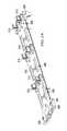
- FIGS. 4A and 4Beach illustrate a perspective view of example subassembly 202 , in accordance with embodiments of the present disclosure.
- subassembly 202may include features for guiding, alignment, and retention of subassembly 202 within chassis 100 , as well as features for guiding, alignment, and retention of information handling resources (e.g., memory risers 114 and/or air movers 122 ) within subassembly 202 .
- information handling resourcese.g., memory risers 114 and/or air movers 122
- subassembly 202may include a handle 402 which may be movable relative to the rest of subassembly 202 and which may be mechanically coupled to one or more standoffs 404 configured to engage with a corresponding feature of chassis 100 to mechanically retain subassembly 202 within chassis 100 .
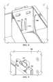
- FIG. 5shows a standoff 404 engaged with a corresponding slot 502 of chassis 100 to retain subassembly 202 in chassis 100 .
- Handle 402may be mechanically coupled to standoffs 404 such that in a closed position of handle 402 (e.g., FIG.
- standoffs 404engage with slots 502 to retain subassembly 202 in chassis 100 , while in an open position of handle 402 (e.g., FIG. 4B ), standoffs 404 may be in a position to be inserted into or removed from slots 502 .
- subassembly 202may include one or more guide slots 406 configured to engage with a corresponding feature of chassis 100 to mechanically guide subassembly 202 within chassis 100 during insertion and removal of subassembly 202 .
- FIG. 6shows a guide slot 406 engaged with a corresponding guide 602 of chassis 100 to guide subassembly 202 during insertion into and removal from chassis 100 .
- guide slots 406 and corresponding guides 602may provide coarse alignment of subassembly 202 within chassis 100 .
- subassembly 202may include one or more openings 702 at the bottom thereof to engage with a corresponding conical post 704 of chassis 100 or formed on a base structure itself mechanically coupled to chassis 100 .
- subassembly 202may include one or more lockout features 410 configured to engage with a corresponding feature of chassis 100 in order to retain subassembly 202 in chassis 100 when an information handling resource is disposed in subassembly 202 .
- each of one or more of air mover bays 408 of subassembly 202may include one or more lockout features 410 .
- lockout feature 410When an air mover 122 is inserted in a corresponding bay 408 , such air mover 122 may activate a lockout feature 410 such that a portion of lockout feature 410 protrudes through a corresponding hole of subassembly 202 as is shown in more detail in FIG. 9 . If lockout feature 410 is activated while subassembly 202 resides in chassis 100 , lockout feature 410 may engage with chassis 100 preventing removal of subassembly 202 from chassis 100 while an air mover 122 remains in a bay 408 which has such lockout feature 410 .
- lockout feature 410may engage with chassis 100 if insertion is attempted, thus preventing insertion of subassembly 202 into chassis 100 while an air mover 122 remains in a bay 408 which has such lockout feature 410 .
- subassembly 402may also include alignment features 414 for receiving corresponding features of a cover of chassis 100 .
- references in the appended claims to an apparatus or system or a component of an apparatus or system being adapted to, arranged to, capable of, configured to, enabled to, operable to, or operative to perform a particular functionencompasses that apparatus, system, or component, whether or not it or that particular function is activated, turned on, or unlocked, as long as that apparatus, system, or component is so adapted, arranged, capable, configured, enabled, operable, or operative.
Landscapes
- Engineering & Computer Science (AREA)
- Theoretical Computer Science (AREA)
- General Engineering & Computer Science (AREA)
- Physics & Mathematics (AREA)
- Computer Hardware Design (AREA)
- Human Computer Interaction (AREA)
- Microelectronics & Electronic Packaging (AREA)
- General Physics & Mathematics (AREA)
- Power Engineering (AREA)
- Computer Security & Cryptography (AREA)
- Thermal Sciences (AREA)
- Mounting Of Printed Circuit Boards And The Like (AREA)
- Cooling Or The Like Of Electrical Apparatus (AREA)
Abstract
Description
Claims (14)
Priority Applications (1)
| Application Number | Priority Date | Filing Date | Title |
|---|---|---|---|
| US14/479,928US9811128B2 (en) | 2014-09-08 | 2014-09-08 | Structural subassembly for use in an information handling system chassis |
Applications Claiming Priority (1)
| Application Number | Priority Date | Filing Date | Title |
|---|---|---|---|
| US14/479,928US9811128B2 (en) | 2014-09-08 | 2014-09-08 | Structural subassembly for use in an information handling system chassis |
Publications (2)
| Publication Number | Publication Date |
|---|---|
| US20160073554A1 US20160073554A1 (en) | 2016-03-10 |
| US9811128B2true US9811128B2 (en) | 2017-11-07 |
Family
ID=55438896
Family Applications (1)
| Application Number | Title | Priority Date | Filing Date |
|---|---|---|---|
| US14/479,928ActiveUS9811128B2 (en) | 2014-09-08 | 2014-09-08 | Structural subassembly for use in an information handling system chassis |
Country Status (1)
| Country | Link |
|---|---|
| US (1) | US9811128B2 (en) |
Cited By (1)
| Publication number | Priority date | Publication date | Assignee | Title |
|---|---|---|---|---|
| US10244651B2 (en)* | 2017-05-25 | 2019-03-26 | Dell Products L.P. | Multi-form factor power supply bay system |
Families Citing this family (11)
| Publication number | Priority date | Publication date | Assignee | Title |
|---|---|---|---|---|
| US20160217097A1 (en)* | 2015-01-26 | 2016-07-28 | Hewlett-Packard Development Company, L.P. | Storage device carrier assembly |
| US9769958B2 (en)* | 2015-09-21 | 2017-09-19 | Ciena Corporation | Modular fan and motherboard assembly |
| TWI583293B (en)* | 2015-12-28 | 2017-05-11 | 鴻海精密工業股份有限公司 | Fixing device |
| TWI625090B (en)* | 2016-05-30 | 2018-05-21 | 仁寶電腦工業股份有限公司 | Chassis structure |
| US10939578B2 (en)* | 2017-08-30 | 2021-03-02 | Dell Products L.P. | Fan tray system |
| US10104803B1 (en)* | 2017-09-07 | 2018-10-16 | Aic Inc. | Conveying apparatus with lift mechanism |
| CN110658892B (en)* | 2018-06-28 | 2021-04-02 | 纬联电子科技(中山)有限公司 | Detachable assembling device |
| CN111417278B (en)* | 2019-01-08 | 2021-04-30 | 纬联电子科技(中山)有限公司 | Electronic device and tray |
| US11073874B2 (en)* | 2019-07-10 | 2021-07-27 | Dell Products L.P. | Apparatus and method for controlled ejection of an open compute project module from an information handling system |
| US11665860B2 (en)* | 2021-10-20 | 2023-05-30 | Dell Products L.P. | Fan carrier system for an information handling system |
| US11822810B2 (en)* | 2021-10-25 | 2023-11-21 | Dell Products L.P. | Removable memory device of a network switch for an information handling system |
Citations (37)
| Publication number | Priority date | Publication date | Assignee | Title |
|---|---|---|---|---|
| US3548425A (en)* | 1968-05-01 | 1970-12-22 | Toby Goldstein | Abutment interlock mechanism |
| US4725244A (en)* | 1987-07-02 | 1988-02-16 | Tektronix, Inc. | System for assembling an electronic work station |
| US4937806A (en)* | 1988-02-12 | 1990-06-26 | Mdb Systems, Inc. | Shock-isolated portable mass data storage device |
| US5214574A (en)* | 1992-04-16 | 1993-05-25 | Chang Bo E | Portable computer housing in combination with a portable computer |
| US5224019A (en)* | 1991-03-15 | 1993-06-29 | Amkly Systems, Inc. | Modular computer assembly |
| US5297009A (en)* | 1991-06-25 | 1994-03-22 | Audio Visuel Systemes | Device for locking in a rack a drawer for electronic board(s) |
| US5313596A (en)* | 1993-01-05 | 1994-05-17 | Dell Usa Lp | Motorized portable computer/expansion chassis docking system |
| US5477415A (en)* | 1993-11-12 | 1995-12-19 | Texas Instruments Incorporated | Automatic computer docking station having a motorized tray, cammed side connectors, motorized side connectors, and locking and unlocking guide pins |
| US5527104A (en)* | 1994-04-06 | 1996-06-18 | Dell Usa, L. P. | Computer chassis cover alignment apparatus |
| US5845978A (en)* | 1995-02-10 | 1998-12-08 | Samsung Electronics Co., Ltd. | Handle apparatus for a computer |
| US5852739A (en)* | 1997-10-08 | 1998-12-22 | Dell Computer Corporation | Low profile plate interlock mechanism for a computer chassis |
| US5949652A (en)* | 1997-10-24 | 1999-09-07 | Dell U.S.A., L.P. | Computer power supply insertion and extraction apparatus and method |
| US5949645A (en)* | 1997-06-02 | 1999-09-07 | Northern Telecom Limited | Electronic unit |
| US6005770A (en)* | 1997-11-12 | 1999-12-21 | Dell U.S.A., L.P. | Computer and a system and method for cooling the interior of the computer |
| US6029183A (en)* | 1996-08-29 | 2000-02-22 | Xybernaut Corporation | Transferable core computer |
| US6029215A (en)* | 1994-11-08 | 2000-02-22 | Texas Instruments Incorporated | Computer ducking station with internal microprocessor |
| US6052281A (en)* | 1999-02-12 | 2000-04-18 | Compaq Computer Corporation | Computer chassis with airflow control mechanisms |
| US6137684A (en)* | 1998-04-21 | 2000-10-24 | International Business Machines Corporation | Camming mechanism for joining modular electronic enclosures |
| US6222736B1 (en)* | 1999-01-26 | 2001-04-24 | Dell Usa, L.P. | Computer with component installation handle |
| US6231144B1 (en)* | 1999-03-16 | 2001-05-15 | Hon Hai Precision Ind. Co., Ltd. | Removable chassis for electronic device |
| US6426876B1 (en)* | 2000-12-19 | 2002-07-30 | Nortel Networks Limited | Circuit pack handling system |
| US20030063454A1 (en)* | 2001-10-03 | 2003-04-03 | Wilson Jeremy I. | Low profile PCI hot plug actuator assembly |
| US20040240186A1 (en)* | 2003-05-30 | 2004-12-02 | Tatung Co., Ltd. | Computer case having pull bar structure for removing front panel |
| US20050152106A1 (en)* | 2004-01-08 | 2005-07-14 | Apple Computer, Inc. | Quick release structures for a computer |
| US20050157463A1 (en)* | 2004-01-15 | 2005-07-21 | Cheng-Chung Hsu | Modularized electronic device assembly architecture |
| US20060044775A1 (en)* | 2004-08-31 | 2006-03-02 | Kabushiki Kaisha Toshiba | Case for electronic equipment and communication device |
| US20060082965A1 (en)* | 2004-10-20 | 2006-04-20 | Paul Walker | Securing computer equipment |
| US20060274515A1 (en)* | 2005-06-04 | 2006-12-07 | Tellabs San Jose, Inc. | Methods and apparatus for a configurable chassis |
| US20090080165A1 (en)* | 2007-09-20 | 2009-03-26 | International Business Machines Corporation | Mechanically-Assisted Insertion and Removal of Modular Device |
| US20090103258A1 (en)* | 2007-09-24 | 2009-04-23 | Ryan Signer | Shoulder screw and handle drive mounting system |
| US20090273901A1 (en)* | 2008-05-05 | 2009-11-05 | Dell Products L.P. | Electrical Coupler Mating System |
| US20120020016A1 (en)* | 2010-02-11 | 2012-01-26 | Liang-Ho Cheng | Tower computer system |
| US8231396B2 (en)* | 2010-05-19 | 2012-07-31 | Abb Technology Ag | Plug-in-unit assembly with an off-center pivotal connection between a handle and an actuating member |
| US20130107424A1 (en)* | 2011-10-27 | 2013-05-02 | Cisco Technology, Inc. | Latching injector/ejector |
| US20140092550A1 (en)* | 2011-06-15 | 2014-04-03 | Hewlett-Packard Development Company, L.P. | Thermal chamber partition and fan unit for computer system |
| US20150146372A1 (en)* | 2013-11-26 | 2015-05-28 | International Business Machines Corporation | Handle lockout mechanism for scaling blade-style servers |
| US9215828B1 (en)* | 2014-11-26 | 2015-12-15 | Inventec (Pudong) Technology Corporation | Server case assembly |
- 2014
- 2014-09-08USUS14/479,928patent/US9811128B2/enactiveActive
Patent Citations (43)
| Publication number | Priority date | Publication date | Assignee | Title |
|---|---|---|---|---|
| US3548425A (en)* | 1968-05-01 | 1970-12-22 | Toby Goldstein | Abutment interlock mechanism |
| US4725244A (en)* | 1987-07-02 | 1988-02-16 | Tektronix, Inc. | System for assembling an electronic work station |
| US4937806A (en)* | 1988-02-12 | 1990-06-26 | Mdb Systems, Inc. | Shock-isolated portable mass data storage device |
| US5224019A (en)* | 1991-03-15 | 1993-06-29 | Amkly Systems, Inc. | Modular computer assembly |
| US5297009A (en)* | 1991-06-25 | 1994-03-22 | Audio Visuel Systemes | Device for locking in a rack a drawer for electronic board(s) |
| US5214574A (en)* | 1992-04-16 | 1993-05-25 | Chang Bo E | Portable computer housing in combination with a portable computer |
| US5313596A (en)* | 1993-01-05 | 1994-05-17 | Dell Usa Lp | Motorized portable computer/expansion chassis docking system |
| US5477415A (en)* | 1993-11-12 | 1995-12-19 | Texas Instruments Incorporated | Automatic computer docking station having a motorized tray, cammed side connectors, motorized side connectors, and locking and unlocking guide pins |
| US5527104A (en)* | 1994-04-06 | 1996-06-18 | Dell Usa, L. P. | Computer chassis cover alignment apparatus |
| US6029215A (en)* | 1994-11-08 | 2000-02-22 | Texas Instruments Incorporated | Computer ducking station with internal microprocessor |
| US5845978A (en)* | 1995-02-10 | 1998-12-08 | Samsung Electronics Co., Ltd. | Handle apparatus for a computer |
| US6029183A (en)* | 1996-08-29 | 2000-02-22 | Xybernaut Corporation | Transferable core computer |
| US5949645A (en)* | 1997-06-02 | 1999-09-07 | Northern Telecom Limited | Electronic unit |
| US5852739A (en)* | 1997-10-08 | 1998-12-22 | Dell Computer Corporation | Low profile plate interlock mechanism for a computer chassis |
| US5949652A (en)* | 1997-10-24 | 1999-09-07 | Dell U.S.A., L.P. | Computer power supply insertion and extraction apparatus and method |
| US6005770A (en)* | 1997-11-12 | 1999-12-21 | Dell U.S.A., L.P. | Computer and a system and method for cooling the interior of the computer |
| US6137684A (en)* | 1998-04-21 | 2000-10-24 | International Business Machines Corporation | Camming mechanism for joining modular electronic enclosures |
| US6222736B1 (en)* | 1999-01-26 | 2001-04-24 | Dell Usa, L.P. | Computer with component installation handle |
| US6052281A (en)* | 1999-02-12 | 2000-04-18 | Compaq Computer Corporation | Computer chassis with airflow control mechanisms |
| US6231144B1 (en)* | 1999-03-16 | 2001-05-15 | Hon Hai Precision Ind. Co., Ltd. | Removable chassis for electronic device |
| US6426876B1 (en)* | 2000-12-19 | 2002-07-30 | Nortel Networks Limited | Circuit pack handling system |
| US20030063454A1 (en)* | 2001-10-03 | 2003-04-03 | Wilson Jeremy I. | Low profile PCI hot plug actuator assembly |
| US20040240186A1 (en)* | 2003-05-30 | 2004-12-02 | Tatung Co., Ltd. | Computer case having pull bar structure for removing front panel |
| US20050152106A1 (en)* | 2004-01-08 | 2005-07-14 | Apple Computer, Inc. | Quick release structures for a computer |
| US20050157463A1 (en)* | 2004-01-15 | 2005-07-21 | Cheng-Chung Hsu | Modularized electronic device assembly architecture |
| US20060044775A1 (en)* | 2004-08-31 | 2006-03-02 | Kabushiki Kaisha Toshiba | Case for electronic equipment and communication device |
| US20060082965A1 (en)* | 2004-10-20 | 2006-04-20 | Paul Walker | Securing computer equipment |
| US7227747B2 (en)* | 2004-10-20 | 2007-06-05 | Hewlett-Packard Development Company, L.P. | Securing computer equipment |
| US20060274515A1 (en)* | 2005-06-04 | 2006-12-07 | Tellabs San Jose, Inc. | Methods and apparatus for a configurable chassis |
| US20090080165A1 (en)* | 2007-09-20 | 2009-03-26 | International Business Machines Corporation | Mechanically-Assisted Insertion and Removal of Modular Device |
| US7675754B2 (en)* | 2007-09-20 | 2010-03-09 | International Business Machines Corporation | Mechanically-assisted insertion and removal of modular device |
| US7576977B2 (en)* | 2007-09-24 | 2009-08-18 | Lsi Logic Corporation | Shoulder screw and handle drive mounting system |
| US20090103258A1 (en)* | 2007-09-24 | 2009-04-23 | Ryan Signer | Shoulder screw and handle drive mounting system |
| US20090273901A1 (en)* | 2008-05-05 | 2009-11-05 | Dell Products L.P. | Electrical Coupler Mating System |
| US7771218B2 (en)* | 2008-05-05 | 2010-08-10 | Dell Products L.P. | Electrical coupler mating system |
| US20120020016A1 (en)* | 2010-02-11 | 2012-01-26 | Liang-Ho Cheng | Tower computer system |
| US8231396B2 (en)* | 2010-05-19 | 2012-07-31 | Abb Technology Ag | Plug-in-unit assembly with an off-center pivotal connection between a handle and an actuating member |
| US20140092550A1 (en)* | 2011-06-15 | 2014-04-03 | Hewlett-Packard Development Company, L.P. | Thermal chamber partition and fan unit for computer system |
| US9310860B2 (en)* | 2011-06-15 | 2016-04-12 | Hewlett-Packard Development Company, L.P. | Thermal chamber partition and fan unit for computer system |
| US20130107424A1 (en)* | 2011-10-27 | 2013-05-02 | Cisco Technology, Inc. | Latching injector/ejector |
| US8611103B2 (en)* | 2011-10-27 | 2013-12-17 | Cisco Technology, Inc. | Latching injector/ejector |
| US20150146372A1 (en)* | 2013-11-26 | 2015-05-28 | International Business Machines Corporation | Handle lockout mechanism for scaling blade-style servers |
| US9215828B1 (en)* | 2014-11-26 | 2015-12-15 | Inventec (Pudong) Technology Corporation | Server case assembly |
Non-Patent Citations (1)
| Title |
|---|
| U.S. Appl. No. 14/474,857, "Systems and Methods for Insertion of an Information Handling Resource in an Information Handling System", filed Sep. 2, 2014, 51 pages. |
Cited By (2)
| Publication number | Priority date | Publication date | Assignee | Title |
|---|---|---|---|---|
| US10244651B2 (en)* | 2017-05-25 | 2019-03-26 | Dell Products L.P. | Multi-form factor power supply bay system |
| US10492330B2 (en)* | 2017-05-25 | 2019-11-26 | Dell Products L.P. | Multi-form factor power supply bay system |
Also Published As
| Publication number | Publication date |
|---|---|
| US20160073554A1 (en) | 2016-03-10 |
Similar Documents
| Publication | Publication Date | Title |
|---|---|---|
| US9811128B2 (en) | Structural subassembly for use in an information handling system chassis | |
| US11216403B2 (en) | Portable computing system and portable computer for use with same | |
| US10359815B1 (en) | Adaptable storage bay for solid state drives | |
| US10660232B1 (en) | Mobile data center | |
| US7746654B2 (en) | Adaptable plug-in mezzanine card for blade servers | |
| US7453707B2 (en) | Tool-less, translating hard drive bay | |
| US9706675B2 (en) | Systems and methods for insertion of an information handling resource in an information handling system | |
| US9706688B2 (en) | Systems and methods for heat management of an information handling resource in an information handling system | |
| US11113228B2 (en) | Portable computing system and portable computer for use with same | |
| US10649491B2 (en) | Mobile data center | |
| CA2998949A1 (en) | Portable computing system and portable computer for use with same | |
| EP3379405A1 (en) | Portable computing system and portable computer for use with same | |
| US9521757B2 (en) | Systems and methods for loading of a component | |
| US11334127B2 (en) | Convertible cold aisle and hot aisle cooling solutions with a common chassis design | |
| US11968797B2 (en) | Memory devices, carriers for same, and related computing systems and methods | |
| US9591775B2 (en) | Mezzanine-style structure with integrated wiring harness | |
| CN102999125B (en) | fan bracket | |
| US9927850B2 (en) | Systems and methods for reducing vibration associated with a component in an information handling system | |
| US9886067B2 (en) | Systems and methods for tool-less board to board coupling | |
| US20250203802A1 (en) | Modular design for tray carrying air mover and drive backplane | |
| US12379754B2 (en) | Air mover assembly | |
| EP3271793B1 (en) | Mobile data center |
Legal Events
| Date | Code | Title | Description |
|---|---|---|---|
| AS | Assignment | Owner name:DELL PRODUCTS L.P., TEXAS Free format text:ASSIGNMENT OF ASSIGNORS INTEREST;ASSIGNORS:MARCADE, MICHAEL DENNIS;HARTMAN, COREY DEAN;PAV, DARREN B.;AND OTHERS;SIGNING DATES FROM 20140829 TO 20140908;REEL/FRAME:033692/0049 | |
| AS | Assignment | Owner name:THE BANK OF NEW YORK MELLON TRUST COMPANY, N.A., AS NOTES COLLATERAL AGENT, TEXAS Free format text:SUPPLEMENT TO PATENT SECURITY AGREEMENT (NOTES);ASSIGNORS:DELL PRODUCTS L.P.;DELL SOFTWARE INC.;FORCE10 NETWORKS, INC.;AND OTHERS;REEL/FRAME:034590/0731 Effective date:20141205 Owner name:BANK OF AMERICA, N.A., AS COLLATERAL AGENT, NORTH CAROLINA Free format text:SUPPLEMENT TO PATENT SECURITY AGREEMENT (TERM LOAN);ASSIGNORS:DELL PRODUCTS L.P.;DELL SOFTWARE INC.;FORCE10 NETWORKS, INC.;AND OTHERS;REEL/FRAME:034591/0391 Effective date:20141205 Owner name:BANK OF AMERICA, N.A., AS ADMINISTRATIVE AGENT, NORTH CAROLINA Free format text:SUPPLEMENT TO PATENT SECURITY AGREEMENT (ABL);ASSIGNORS:DELL PRODUCTS L.P.;DELL SOFTWARE INC.;FORCE10 NETWORKS, INC.;AND OTHERS;REEL/FRAME:034590/0696 Effective date:20141205 Owner name:THE BANK OF NEW YORK MELLON TRUST COMPANY, N.A., A Free format text:SUPPLEMENT TO PATENT SECURITY AGREEMENT (NOTES);ASSIGNORS:DELL PRODUCTS L.P.;DELL SOFTWARE INC.;FORCE10 NETWORKS, INC.;AND OTHERS;REEL/FRAME:034590/0731 Effective date:20141205 Owner name:BANK OF AMERICA, N.A., AS ADMINISTRATIVE AGENT, NO Free format text:SUPPLEMENT TO PATENT SECURITY AGREEMENT (ABL);ASSIGNORS:DELL PRODUCTS L.P.;DELL SOFTWARE INC.;FORCE10 NETWORKS, INC.;AND OTHERS;REEL/FRAME:034590/0696 Effective date:20141205 Owner name:BANK OF AMERICA, N.A., AS COLLATERAL AGENT, NORTH Free format text:SUPPLEMENT TO PATENT SECURITY AGREEMENT (TERM LOAN);ASSIGNORS:DELL PRODUCTS L.P.;DELL SOFTWARE INC.;FORCE10 NETWORKS, INC.;AND OTHERS;REEL/FRAME:034591/0391 Effective date:20141205 | |
| AS | Assignment | Owner name:DELL PRODUCTS L.P., TEXAS Free format text:RELEASE OF REEL 034590 FRAME 0696 (ABL);ASSIGNOR:BANK OF AMERICA, N.A., AS ADMINISTRATIVE AGENT;REEL/FRAME:040016/0964 Effective date:20160907 | |
| AS | Assignment | Owner name:DELL PRODUCTS L.P., TEXAS Free format text:RELEASE OF REEL 034590 FRAME 0731 (NOTE);ASSIGNOR:BANK OF NEW YORK MELLON TRUST COMPANY, N.A., AS COLLATERAL AGENT;REEL/FRAME:040027/0070 Effective date:20160907 Owner name:DELL PRODUCTS L.P., TEXAS Free format text:RELEASE OF REEL 034591 FRAME 0391 (TL);ASSIGNOR:BANK OF AMERICA, N.A., AS COLLATERAL AGENT;REEL/FRAME:040027/0719 Effective date:20160907 | |
| AS | Assignment | Owner name:CREDIT SUISSE AG, CAYMAN ISLANDS BRANCH, AS COLLATERAL AGENT, NORTH CAROLINA Free format text:SECURITY AGREEMENT;ASSIGNORS:ASAP SOFTWARE EXPRESS, INC.;AVENTAIL LLC;CREDANT TECHNOLOGIES, INC.;AND OTHERS;REEL/FRAME:040134/0001 Effective date:20160907 Owner name:THE BANK OF NEW YORK MELLON TRUST COMPANY, N.A., AS NOTES COLLATERAL AGENT, TEXAS Free format text:SECURITY AGREEMENT;ASSIGNORS:ASAP SOFTWARE EXPRESS, INC.;AVENTAIL LLC;CREDANT TECHNOLOGIES, INC.;AND OTHERS;REEL/FRAME:040136/0001 Effective date:20160907 Owner name:CREDIT SUISSE AG, CAYMAN ISLANDS BRANCH, AS COLLAT Free format text:SECURITY AGREEMENT;ASSIGNORS:ASAP SOFTWARE EXPRESS, INC.;AVENTAIL LLC;CREDANT TECHNOLOGIES, INC.;AND OTHERS;REEL/FRAME:040134/0001 Effective date:20160907 Owner name:THE BANK OF NEW YORK MELLON TRUST COMPANY, N.A., A Free format text:SECURITY AGREEMENT;ASSIGNORS:ASAP SOFTWARE EXPRESS, INC.;AVENTAIL LLC;CREDANT TECHNOLOGIES, INC.;AND OTHERS;REEL/FRAME:040136/0001 Effective date:20160907 | |
| STCF | Information on status: patent grant | Free format text:PATENTED CASE | |
| AS | Assignment | Owner name:THE BANK OF NEW YORK MELLON TRUST COMPANY, N.A., T Free format text:SECURITY AGREEMENT;ASSIGNORS:CREDANT TECHNOLOGIES, INC.;DELL INTERNATIONAL L.L.C.;DELL MARKETING L.P.;AND OTHERS;REEL/FRAME:049452/0223 Effective date:20190320 Owner name:THE BANK OF NEW YORK MELLON TRUST COMPANY, N.A., TEXAS Free format text:SECURITY AGREEMENT;ASSIGNORS:CREDANT TECHNOLOGIES, INC.;DELL INTERNATIONAL L.L.C.;DELL MARKETING L.P.;AND OTHERS;REEL/FRAME:049452/0223 Effective date:20190320 | |
| AS | Assignment | Owner name:THE BANK OF NEW YORK MELLON TRUST COMPANY, N.A., TEXAS Free format text:SECURITY AGREEMENT;ASSIGNORS:CREDANT TECHNOLOGIES INC.;DELL INTERNATIONAL L.L.C.;DELL MARKETING L.P.;AND OTHERS;REEL/FRAME:053546/0001 Effective date:20200409 | |
| MAFP | Maintenance fee payment | Free format text:PAYMENT OF MAINTENANCE FEE, 4TH YEAR, LARGE ENTITY (ORIGINAL EVENT CODE: M1551); ENTITY STATUS OF PATENT OWNER: LARGE ENTITY Year of fee payment:4 | |
| AS | Assignment | Owner name:WYSE TECHNOLOGY L.L.C., CALIFORNIA Free format text:RELEASE BY SECURED PARTY;ASSIGNOR:CREDIT SUISSE AG, CAYMAN ISLANDS BRANCH;REEL/FRAME:058216/0001 Effective date:20211101 Owner name:SCALEIO LLC, MASSACHUSETTS Free format text:RELEASE BY SECURED PARTY;ASSIGNOR:CREDIT SUISSE AG, CAYMAN ISLANDS BRANCH;REEL/FRAME:058216/0001 Effective date:20211101 Owner name:MOZY, INC., WASHINGTON Free format text:RELEASE BY SECURED PARTY;ASSIGNOR:CREDIT SUISSE AG, CAYMAN ISLANDS BRANCH;REEL/FRAME:058216/0001 Effective date:20211101 Owner name:MAGINATICS LLC, CALIFORNIA Free format text:RELEASE BY SECURED PARTY;ASSIGNOR:CREDIT SUISSE AG, CAYMAN ISLANDS BRANCH;REEL/FRAME:058216/0001 Effective date:20211101 Owner name:FORCE10 NETWORKS, INC., CALIFORNIA Free format text:RELEASE BY SECURED PARTY;ASSIGNOR:CREDIT SUISSE AG, CAYMAN ISLANDS BRANCH;REEL/FRAME:058216/0001 Effective date:20211101 Owner name:EMC IP HOLDING COMPANY LLC, TEXAS Free format text:RELEASE BY SECURED PARTY;ASSIGNOR:CREDIT SUISSE AG, CAYMAN ISLANDS BRANCH;REEL/FRAME:058216/0001 Effective date:20211101 Owner name:EMC CORPORATION, MASSACHUSETTS Free format text:RELEASE BY SECURED PARTY;ASSIGNOR:CREDIT SUISSE AG, CAYMAN ISLANDS BRANCH;REEL/FRAME:058216/0001 Effective date:20211101 Owner name:DELL SYSTEMS CORPORATION, TEXAS Free format text:RELEASE BY SECURED PARTY;ASSIGNOR:CREDIT SUISSE AG, CAYMAN ISLANDS BRANCH;REEL/FRAME:058216/0001 Effective date:20211101 Owner name:DELL SOFTWARE INC., CALIFORNIA Free format text:RELEASE BY SECURED PARTY;ASSIGNOR:CREDIT SUISSE AG, CAYMAN ISLANDS BRANCH;REEL/FRAME:058216/0001 Effective date:20211101 Owner name:DELL PRODUCTS L.P., TEXAS Free format text:RELEASE BY SECURED PARTY;ASSIGNOR:CREDIT SUISSE AG, CAYMAN ISLANDS BRANCH;REEL/FRAME:058216/0001 Effective date:20211101 Owner name:DELL MARKETING L.P., TEXAS Free format text:RELEASE BY SECURED PARTY;ASSIGNOR:CREDIT SUISSE AG, CAYMAN ISLANDS BRANCH;REEL/FRAME:058216/0001 Effective date:20211101 Owner name:DELL INTERNATIONAL, L.L.C., TEXAS Free format text:RELEASE BY SECURED PARTY;ASSIGNOR:CREDIT SUISSE AG, CAYMAN ISLANDS BRANCH;REEL/FRAME:058216/0001 Effective date:20211101 Owner name:DELL USA L.P., TEXAS Free format text:RELEASE BY SECURED PARTY;ASSIGNOR:CREDIT SUISSE AG, CAYMAN ISLANDS BRANCH;REEL/FRAME:058216/0001 Effective date:20211101 Owner name:CREDANT TECHNOLOGIES, INC., TEXAS Free format text:RELEASE BY SECURED PARTY;ASSIGNOR:CREDIT SUISSE AG, CAYMAN ISLANDS BRANCH;REEL/FRAME:058216/0001 Effective date:20211101 Owner name:AVENTAIL LLC, CALIFORNIA Free format text:RELEASE BY SECURED PARTY;ASSIGNOR:CREDIT SUISSE AG, CAYMAN ISLANDS BRANCH;REEL/FRAME:058216/0001 Effective date:20211101 Owner name:ASAP SOFTWARE EXPRESS, INC., ILLINOIS Free format text:RELEASE BY SECURED PARTY;ASSIGNOR:CREDIT SUISSE AG, CAYMAN ISLANDS BRANCH;REEL/FRAME:058216/0001 Effective date:20211101 | |
| AS | Assignment | Owner name:SCALEIO LLC, MASSACHUSETTS Free format text:RELEASE OF SECURITY INTEREST IN PATENTS PREVIOUSLY RECORDED AT REEL/FRAME (040136/0001);ASSIGNOR:THE BANK OF NEW YORK MELLON TRUST COMPANY, N.A., AS NOTES COLLATERAL AGENT;REEL/FRAME:061324/0001 Effective date:20220329 Owner name:EMC IP HOLDING COMPANY LLC (ON BEHALF OF ITSELF AND AS SUCCESSOR-IN-INTEREST TO MOZY, INC.), TEXAS Free format text:RELEASE OF SECURITY INTEREST IN PATENTS PREVIOUSLY RECORDED AT REEL/FRAME (040136/0001);ASSIGNOR:THE BANK OF NEW YORK MELLON TRUST COMPANY, N.A., AS NOTES COLLATERAL AGENT;REEL/FRAME:061324/0001 Effective date:20220329 Owner name:EMC CORPORATION (ON BEHALF OF ITSELF AND AS SUCCESSOR-IN-INTEREST TO MAGINATICS LLC), MASSACHUSETTS Free format text:RELEASE OF SECURITY INTEREST IN PATENTS PREVIOUSLY RECORDED AT REEL/FRAME (040136/0001);ASSIGNOR:THE BANK OF NEW YORK MELLON TRUST COMPANY, N.A., AS NOTES COLLATERAL AGENT;REEL/FRAME:061324/0001 Effective date:20220329 Owner name:DELL MARKETING CORPORATION (SUCCESSOR-IN-INTEREST TO FORCE10 NETWORKS, INC. AND WYSE TECHNOLOGY L.L.C.), TEXAS Free format text:RELEASE OF SECURITY INTEREST IN PATENTS PREVIOUSLY RECORDED AT REEL/FRAME (040136/0001);ASSIGNOR:THE BANK OF NEW YORK MELLON TRUST COMPANY, N.A., AS NOTES COLLATERAL AGENT;REEL/FRAME:061324/0001 Effective date:20220329 Owner name:DELL PRODUCTS L.P., TEXAS Free format text:RELEASE OF SECURITY INTEREST IN PATENTS PREVIOUSLY RECORDED AT REEL/FRAME (040136/0001);ASSIGNOR:THE BANK OF NEW YORK MELLON TRUST COMPANY, N.A., AS NOTES COLLATERAL AGENT;REEL/FRAME:061324/0001 Effective date:20220329 Owner name:DELL INTERNATIONAL L.L.C., TEXAS Free format text:RELEASE OF SECURITY INTEREST IN PATENTS PREVIOUSLY RECORDED AT REEL/FRAME (040136/0001);ASSIGNOR:THE BANK OF NEW YORK MELLON TRUST COMPANY, N.A., AS NOTES COLLATERAL AGENT;REEL/FRAME:061324/0001 Effective date:20220329 Owner name:DELL USA L.P., TEXAS Free format text:RELEASE OF SECURITY INTEREST IN PATENTS PREVIOUSLY RECORDED AT REEL/FRAME (040136/0001);ASSIGNOR:THE BANK OF NEW YORK MELLON TRUST COMPANY, N.A., AS NOTES COLLATERAL AGENT;REEL/FRAME:061324/0001 Effective date:20220329 Owner name:DELL MARKETING L.P. (ON BEHALF OF ITSELF AND AS SUCCESSOR-IN-INTEREST TO CREDANT TECHNOLOGIES, INC.), TEXAS Free format text:RELEASE OF SECURITY INTEREST IN PATENTS PREVIOUSLY RECORDED AT REEL/FRAME (040136/0001);ASSIGNOR:THE BANK OF NEW YORK MELLON TRUST COMPANY, N.A., AS NOTES COLLATERAL AGENT;REEL/FRAME:061324/0001 Effective date:20220329 Owner name:DELL MARKETING CORPORATION (SUCCESSOR-IN-INTEREST TO ASAP SOFTWARE EXPRESS, INC.), TEXAS Free format text:RELEASE OF SECURITY INTEREST IN PATENTS PREVIOUSLY RECORDED AT REEL/FRAME (040136/0001);ASSIGNOR:THE BANK OF NEW YORK MELLON TRUST COMPANY, N.A., AS NOTES COLLATERAL AGENT;REEL/FRAME:061324/0001 Effective date:20220329 | |
| AS | Assignment | Owner name:SCALEIO LLC, MASSACHUSETTS Free format text:RELEASE OF SECURITY INTEREST IN PATENTS PREVIOUSLY RECORDED AT REEL/FRAME (045455/0001);ASSIGNOR:THE BANK OF NEW YORK MELLON TRUST COMPANY, N.A., AS NOTES COLLATERAL AGENT;REEL/FRAME:061753/0001 Effective date:20220329 Owner name:EMC IP HOLDING COMPANY LLC (ON BEHALF OF ITSELF AND AS SUCCESSOR-IN-INTEREST TO MOZY, INC.), TEXAS Free format text:RELEASE OF SECURITY INTEREST IN PATENTS PREVIOUSLY RECORDED AT REEL/FRAME (045455/0001);ASSIGNOR:THE BANK OF NEW YORK MELLON TRUST COMPANY, N.A., AS NOTES COLLATERAL AGENT;REEL/FRAME:061753/0001 Effective date:20220329 Owner name:EMC CORPORATION (ON BEHALF OF ITSELF AND AS SUCCESSOR-IN-INTEREST TO MAGINATICS LLC), MASSACHUSETTS Free format text:RELEASE OF SECURITY INTEREST IN PATENTS PREVIOUSLY RECORDED AT REEL/FRAME (045455/0001);ASSIGNOR:THE BANK OF NEW YORK MELLON TRUST COMPANY, N.A., AS NOTES COLLATERAL AGENT;REEL/FRAME:061753/0001 Effective date:20220329 Owner name:DELL MARKETING CORPORATION (SUCCESSOR-IN-INTEREST TO FORCE10 NETWORKS, INC. AND WYSE TECHNOLOGY L.L.C.), TEXAS Free format text:RELEASE OF SECURITY INTEREST IN PATENTS PREVIOUSLY RECORDED AT REEL/FRAME (045455/0001);ASSIGNOR:THE BANK OF NEW YORK MELLON TRUST COMPANY, N.A., AS NOTES COLLATERAL AGENT;REEL/FRAME:061753/0001 Effective date:20220329 Owner name:DELL PRODUCTS L.P., TEXAS Free format text:RELEASE OF SECURITY INTEREST IN PATENTS PREVIOUSLY RECORDED AT REEL/FRAME (045455/0001);ASSIGNOR:THE BANK OF NEW YORK MELLON TRUST COMPANY, N.A., AS NOTES COLLATERAL AGENT;REEL/FRAME:061753/0001 Effective date:20220329 Owner name:DELL INTERNATIONAL L.L.C., TEXAS Free format text:RELEASE OF SECURITY INTEREST IN PATENTS PREVIOUSLY RECORDED AT REEL/FRAME (045455/0001);ASSIGNOR:THE BANK OF NEW YORK MELLON TRUST COMPANY, N.A., AS NOTES COLLATERAL AGENT;REEL/FRAME:061753/0001 Effective date:20220329 Owner name:DELL USA L.P., TEXAS Free format text:RELEASE OF SECURITY INTEREST IN PATENTS PREVIOUSLY RECORDED AT REEL/FRAME (045455/0001);ASSIGNOR:THE BANK OF NEW YORK MELLON TRUST COMPANY, N.A., AS NOTES COLLATERAL AGENT;REEL/FRAME:061753/0001 Effective date:20220329 Owner name:DELL MARKETING L.P. (ON BEHALF OF ITSELF AND AS SUCCESSOR-IN-INTEREST TO CREDANT TECHNOLOGIES, INC.), TEXAS Free format text:RELEASE OF SECURITY INTEREST IN PATENTS PREVIOUSLY RECORDED AT REEL/FRAME (045455/0001);ASSIGNOR:THE BANK OF NEW YORK MELLON TRUST COMPANY, N.A., AS NOTES COLLATERAL AGENT;REEL/FRAME:061753/0001 Effective date:20220329 Owner name:DELL MARKETING CORPORATION (SUCCESSOR-IN-INTEREST TO ASAP SOFTWARE EXPRESS, INC.), TEXAS Free format text:RELEASE OF SECURITY INTEREST IN PATENTS PREVIOUSLY RECORDED AT REEL/FRAME (045455/0001);ASSIGNOR:THE BANK OF NEW YORK MELLON TRUST COMPANY, N.A., AS NOTES COLLATERAL AGENT;REEL/FRAME:061753/0001 Effective date:20220329 | |
| AS | Assignment | Owner name:DELL MARKETING L.P. (ON BEHALF OF ITSELF AND AS SUCCESSOR-IN-INTEREST TO CREDANT TECHNOLOGIES, INC.), TEXAS Free format text:RELEASE OF SECURITY INTEREST IN PATENTS PREVIOUSLY RECORDED AT REEL/FRAME (053546/0001);ASSIGNOR:THE BANK OF NEW YORK MELLON TRUST COMPANY, N.A., AS NOTES COLLATERAL AGENT;REEL/FRAME:071642/0001 Effective date:20220329 Owner name:DELL INTERNATIONAL L.L.C., TEXAS Free format text:RELEASE OF SECURITY INTEREST IN PATENTS PREVIOUSLY RECORDED AT REEL/FRAME (053546/0001);ASSIGNOR:THE BANK OF NEW YORK MELLON TRUST COMPANY, N.A., AS NOTES COLLATERAL AGENT;REEL/FRAME:071642/0001 Effective date:20220329 Owner name:DELL PRODUCTS L.P., TEXAS Free format text:RELEASE OF SECURITY INTEREST IN PATENTS PREVIOUSLY RECORDED AT REEL/FRAME (053546/0001);ASSIGNOR:THE BANK OF NEW YORK MELLON TRUST COMPANY, N.A., AS NOTES COLLATERAL AGENT;REEL/FRAME:071642/0001 Effective date:20220329 Owner name:DELL USA L.P., TEXAS Free format text:RELEASE OF SECURITY INTEREST IN PATENTS PREVIOUSLY RECORDED AT REEL/FRAME (053546/0001);ASSIGNOR:THE BANK OF NEW YORK MELLON TRUST COMPANY, N.A., AS NOTES COLLATERAL AGENT;REEL/FRAME:071642/0001 Effective date:20220329 Owner name:EMC CORPORATION, MASSACHUSETTS Free format text:RELEASE OF SECURITY INTEREST IN PATENTS PREVIOUSLY RECORDED AT REEL/FRAME (053546/0001);ASSIGNOR:THE BANK OF NEW YORK MELLON TRUST COMPANY, N.A., AS NOTES COLLATERAL AGENT;REEL/FRAME:071642/0001 Effective date:20220329 Owner name:DELL MARKETING CORPORATION (SUCCESSOR-IN-INTEREST TO FORCE10 NETWORKS, INC. AND WYSE TECHNOLOGY L.L.C.), TEXAS Free format text:RELEASE OF SECURITY INTEREST IN PATENTS PREVIOUSLY RECORDED AT REEL/FRAME (053546/0001);ASSIGNOR:THE BANK OF NEW YORK MELLON TRUST COMPANY, N.A., AS NOTES COLLATERAL AGENT;REEL/FRAME:071642/0001 Effective date:20220329 Owner name:EMC IP HOLDING COMPANY LLC, TEXAS Free format text:RELEASE OF SECURITY INTEREST IN PATENTS PREVIOUSLY RECORDED AT REEL/FRAME (053546/0001);ASSIGNOR:THE BANK OF NEW YORK MELLON TRUST COMPANY, N.A., AS NOTES COLLATERAL AGENT;REEL/FRAME:071642/0001 Effective date:20220329 | |
| MAFP | Maintenance fee payment | Free format text:PAYMENT OF MAINTENANCE FEE, 8TH YEAR, LARGE ENTITY (ORIGINAL EVENT CODE: M1552); ENTITY STATUS OF PATENT OWNER: LARGE ENTITY Year of fee payment:8 |