US9810441B2 - HVAC controller with indoor air quality scheduling - Google Patents
HVAC controller with indoor air quality schedulingDownload PDFInfo
- Publication number
- US9810441B2 US9810441B2US13/403,878US201213403878AUS9810441B2US 9810441 B2US9810441 B2US 9810441B2US 201213403878 AUS201213403878 AUS 201213403878AUS 9810441 B2US9810441 B2US 9810441B2
- Authority
- US
- United States
- Prior art keywords
- user
- time
- period
- controller
- hvac
- Prior art date
- Legal status (The legal status is an assumption and is not a legal conclusion. Google has not performed a legal analysis and makes no representation as to the accuracy of the status listed.)
- Active, expires
Links
Images


Classifications
- F24F11/0009—
- F24F11/0086—
- F—MECHANICAL ENGINEERING; LIGHTING; HEATING; WEAPONS; BLASTING
- F24—HEATING; RANGES; VENTILATING
- F24F—AIR-CONDITIONING; AIR-HUMIDIFICATION; VENTILATION; USE OF AIR CURRENTS FOR SCREENING
- F24F11/00—Control or safety arrangements
- F24F11/30—Control or safety arrangements for purposes related to the operation of the system, e.g. for safety or monitoring
- F24F11/46—Improving electric energy efficiency or saving
- F24F11/47—Responding to energy costs
- F—MECHANICAL ENGINEERING; LIGHTING; HEATING; WEAPONS; BLASTING
- F24—HEATING; RANGES; VENTILATING
- F24F—AIR-CONDITIONING; AIR-HUMIDIFICATION; VENTILATION; USE OF AIR CURRENTS FOR SCREENING
- F24F11/00—Control or safety arrangements
- F24F11/50—Control or safety arrangements characterised by user interfaces or communication
- F24F11/52—Indication arrangements, e.g. displays
- F24F11/523—Indication arrangements, e.g. displays for displaying temperature data
- F—MECHANICAL ENGINEERING; LIGHTING; HEATING; WEAPONS; BLASTING
- F24—HEATING; RANGES; VENTILATING
- F24F—AIR-CONDITIONING; AIR-HUMIDIFICATION; VENTILATION; USE OF AIR CURRENTS FOR SCREENING
- F24F11/00—Control or safety arrangements
- F24F11/50—Control or safety arrangements characterised by user interfaces or communication
- F24F11/56—Remote control
- F24F11/58—Remote control using Internet communication
- F—MECHANICAL ENGINEERING; LIGHTING; HEATING; WEAPONS; BLASTING
- F24—HEATING; RANGES; VENTILATING
- F24F—AIR-CONDITIONING; AIR-HUMIDIFICATION; VENTILATION; USE OF AIR CURRENTS FOR SCREENING
- F24F11/00—Control or safety arrangements
- F24F11/62—Control or safety arrangements characterised by the type of control or by internal processing, e.g. using fuzzy logic, adaptive control or estimation of values
- F24F11/63—Electronic processing
- F24F11/64—Electronic processing using pre-stored data
- F—MECHANICAL ENGINEERING; LIGHTING; HEATING; WEAPONS; BLASTING
- F24—HEATING; RANGES; VENTILATING
- F24F—AIR-CONDITIONING; AIR-HUMIDIFICATION; VENTILATION; USE OF AIR CURRENTS FOR SCREENING
- F24F11/00—Control or safety arrangements
- F24F11/62—Control or safety arrangements characterised by the type of control or by internal processing, e.g. using fuzzy logic, adaptive control or estimation of values
- F24F11/63—Electronic processing
- F24F11/65—Electronic processing for selecting an operating mode
- F—MECHANICAL ENGINEERING; LIGHTING; HEATING; WEAPONS; BLASTING
- F24—HEATING; RANGES; VENTILATING
- F24F—AIR-CONDITIONING; AIR-HUMIDIFICATION; VENTILATION; USE OF AIR CURRENTS FOR SCREENING
- F24F11/00—Control or safety arrangements
- F24F11/70—Control systems characterised by their outputs; Constructional details thereof
- F24F11/72—Control systems characterised by their outputs; Constructional details thereof for controlling the supply of treated air, e.g. its pressure
- F24F11/74—Control systems characterised by their outputs; Constructional details thereof for controlling the supply of treated air, e.g. its pressure for controlling air flow rate or air velocity
- F24F11/77—Control systems characterised by their outputs; Constructional details thereof for controlling the supply of treated air, e.g. its pressure for controlling air flow rate or air velocity by controlling the speed of ventilators
- G—PHYSICS
- G05—CONTROLLING; REGULATING
- G05B—CONTROL OR REGULATING SYSTEMS IN GENERAL; FUNCTIONAL ELEMENTS OF SUCH SYSTEMS; MONITORING OR TESTING ARRANGEMENTS FOR SUCH SYSTEMS OR ELEMENTS
- G05B15/00—Systems controlled by a computer
- G05B15/02—Systems controlled by a computer electric
- F—MECHANICAL ENGINEERING; LIGHTING; HEATING; WEAPONS; BLASTING
- F24—HEATING; RANGES; VENTILATING
- F24F—AIR-CONDITIONING; AIR-HUMIDIFICATION; VENTILATION; USE OF AIR CURRENTS FOR SCREENING
- F24F11/00—Control or safety arrangements
- F24F11/50—Control or safety arrangements characterised by user interfaces or communication
- F24F11/52—Indication arrangements, e.g. displays
- F—MECHANICAL ENGINEERING; LIGHTING; HEATING; WEAPONS; BLASTING
- F24—HEATING; RANGES; VENTILATING
- F24F—AIR-CONDITIONING; AIR-HUMIDIFICATION; VENTILATION; USE OF AIR CURRENTS FOR SCREENING
- F24F11/00—Control or safety arrangements
- F24F11/50—Control or safety arrangements characterised by user interfaces or communication
- F24F11/56—Remote control
- F24F11/59—Remote control for presetting
- F—MECHANICAL ENGINEERING; LIGHTING; HEATING; WEAPONS; BLASTING
- F24—HEATING; RANGES; VENTILATING
- F24F—AIR-CONDITIONING; AIR-HUMIDIFICATION; VENTILATION; USE OF AIR CURRENTS FOR SCREENING
- F24F11/00—Control or safety arrangements
- F24F11/62—Control or safety arrangements characterised by the type of control or by internal processing, e.g. using fuzzy logic, adaptive control or estimation of values
- F24F11/63—Electronic processing
- F24F11/65—Electronic processing for selecting an operating mode
- F24F11/66—Sleep mode
- F24F2011/0072—
- F24F2011/0091—
- F—MECHANICAL ENGINEERING; LIGHTING; HEATING; WEAPONS; BLASTING
- F24—HEATING; RANGES; VENTILATING
- F24F—AIR-CONDITIONING; AIR-HUMIDIFICATION; VENTILATION; USE OF AIR CURRENTS FOR SCREENING
- F24F2110/00—Control inputs relating to air properties
- F24F2110/10—Temperature
- F—MECHANICAL ENGINEERING; LIGHTING; HEATING; WEAPONS; BLASTING
- F24—HEATING; RANGES; VENTILATING
- F24F—AIR-CONDITIONING; AIR-HUMIDIFICATION; VENTILATION; USE OF AIR CURRENTS FOR SCREENING
- F24F2110/00—Control inputs relating to air properties
- F24F2110/20—Humidity
- F—MECHANICAL ENGINEERING; LIGHTING; HEATING; WEAPONS; BLASTING
- F24—HEATING; RANGES; VENTILATING
- F24F—AIR-CONDITIONING; AIR-HUMIDIFICATION; VENTILATION; USE OF AIR CURRENTS FOR SCREENING
- F24F2120/00—Control inputs relating to users or occupants
- F24F2120/10—Occupancy
Definitions
- the present disclosurerelates generally to HVAC systems, and more particularly, to controllers that may be used for controlling HVAC systems.
- HVACHeating, ventilation, and/or air conditioning
- HVAC systemsare often used to control the comfort level within a building or other structure.
- HVAC systemstypically include an HVAC controller that controls various HVAC components of the HVAC system in order to affect and/or control the temperature within the building.
- Some HVAC systemsinclude one or more HVAC components that are useful for controlling the indoor air quality within the building, such as ventilation components, humidification components, and/or dehumidification components. In many cases, such indoor air quality components are controlled in accordance with a fixed setting that can be manually adjusted by the user.
- the HVAC systemmay include a building controller (e.g. a thermostat) and at least one indoor air quality component such as, for example, a humidifier unit, a dehumidifier unit, and/or a ventilation unit.
- a building controllere.g. a thermostat
- an HVAC controllermay be configured to control one or more components of an HVAC system of a building.
- the HVAC controllermay include a user interface, a memory, a programmable operating schedule including two or more time periods and one or more temperature set points for each of the two or more time periods stored in the memory, an I/O block for sending and/or receiving signals to and/or from the one or more components of the HVAC system, and a controller.
- the controllermay be coupled to the user interface, the memory, and the I/O block, and may be configured to generate one or more signals to control one or more components of the HVAC system in accordance with the predetermined operating schedule.
- the controllermay be configured to allow a user to select at least a first time period of the two or more time periods of the predetermined operating schedule to control at least one of the one or more indoor air quality components of the HVAC system differently than during at least one other of the two or more time periods of the predetermined operating schedule.
- FIG. 1is a schematic view of an illustrative HVAC system servicing a building or structure
- FIG. 2is a schematic view of an illustrative HVAC controller
- FIG. 3is a front view of an illustrative HVAC controller
- FIGS. 4-24show several illustrative screens that may be displayed on the HVAC controllers of FIGS. 2 and 3 when in use.
- FIG. 1is a schematic view of a building 2 having an illustrative heating, ventilation, and air conditioning (HVAC) system 4 . While FIG. 1 shows a typical forced air type HVAC system, other types of HVAC systems are contemplated including, but not limited to, boiler systems, radiant heating systems, electric heating systems, cooling systems, heat pump systems, and/or any other suitable type of HVAC system, as desired.
- the illustrative HVAC system 4 of FIG. 1includes one or more HVAC components 6 , a system of ductwork and air vents including a supply air duct 10 and a return air duct 14 , and at least one HVAC controller 18 .
- the one or more HVAC components 6may include, but are not limited to, a furnace, a heat pump, an electric heat pump, a geothermal heat pump, an electric heating unit, an air conditioning unit, a ventilation unit, a humidifier, a dehumidifier, an air exchanger, an air cleaner, a damper, a valve, and/or the like.
- the HVAC controller(s) 18may be configured to control the comfort level and, in some cases, the air quality conditions in the building or structure by activating and deactivating the HVAC component(s) 6 in a controlled manner.
- the HVAC controller(s) 18may be configured to control the HVAC component(s) 6 via a wired or wireless communication link 20 .
- the HVAC controller(s) 18may wirelessly communicate with the one or more HVAC components(s) 6 following a wireless protocol such as, for example, cellular communication, ZigBee, Bluetooth, WiFi, IrDA, dedicated short range communication (DSRC), EnOcean, or any other suitable wireless protocols, as desired.
- the HVAC controller(s) 18may be a thermostat, such as, for example, a wall mountable thermostat, but this is not required in all embodiments.
- a thermostatmay include (e.g. within the thermostat housing) or have access to a temperature sensor for sensing an ambient temperature at or near the thermostat.
- the HVAC controller(s) 18may be a zone controller, or may include multiple zone controllers each monitoring and/or controlling the comfort level within a particular zone in the building or other structure.
- HVAC controllerwhich is not meant to be limiting in any way, is disclosed in: US Published Patent Application No. 20090140062, entitled “HVAC CONTROLLER THAT SELECTIVELY REPLACES OPERATING INFORMATION ON A DISPLAY WITH SYSTEM STATUS INFORMATION”; US Published Application No. 20090143880, entitled “HVAC CONTROLLER WITH CONTEXT SENSITIVE HELP SCREENS”; US Published Application No. 20090143918, entitled “METHOD AND APPARATUS FOR CONFIGURING AN HVAC CONTROLLER”; US Published Application No.
- the HVAC component(s) 6may provide heated air (and/or cooled air) via the ductwork 10 throughout the building 2 .
- the HVAC component(s) 6may be in fluid communication with every room and/or zone in the building 2 via the ductwork 10 and 14 , but this is not required.
- an HVAC component 6e.g. forced warm air furnace
- the heated airmay be forced through supply air duct 10 by a blower or fan 22 .
- the cooler air from each zonemay be returned to the HVAC component 6 (e.g. forced warm air furnace) for heating via return air ducts 14 .
- an HVAC component 6e.g. air conditioning unit
- the cooled airmay be forced through supply air duct 10 by the blower or fan 22 .
- the warmer air from each zonemay be returned to the HVAC component 6 (e.g. air conditioning unit) for cooling via return air ducts 14 .
- the system of vents or ductwork 10 and/or 14can include one or more dampers 24 to regulate the flow of air, but this is not required.
- one or more dampers 24may be coupled to one or more HVAC controller(s) 18 , and can be coordinated with the operation of one or more HVAC components 6 .
- the one or more HVAC controller(s) 18may actuate dampers 24 to an open position, a closed position, and/or a partially open position to modulate the flow of air from the one or more HVAC components 6 to an appropriate room and/or zone in the building or other structure.
- the dampers 24may be particularly useful in zoned HVAC systems, and may be used to control which zone(s) receives conditioned air from the HVAC component(s) 6 .
- the HVAC component(s) 6may exhaust stale air and/or supply fresh air to the building or structure 2 via the ductwork 10 located throughout the building 2 .
- the HVAC component(s) 6may include a ventilation unit 21 , which may draw outside air into the building via an outside air intake 27 and at the same time expel inside air via an inside air outlet 29 .
- a heat exchanger(not explicitly shown) may be provided to exchange heat between the outgoing inside air and the incoming outside air.
- the ventilation unit 21may include additional fans and/or blowers to facilitate the exchange of stale air from within the building 2 with fresh air supplied from outside the building 2 .
- the ventilation unit 21may include a ventilation controller (not explicitly shown), that may receive ventilation commands from, for example, the HVAC controller(s) 18 , and in response, may activate and/or deactivate the various components of the ventilation unit 21 to implement the received ventilation commands.
- the ventilation unit 21may be coupled to additional ductwork which may draw state air from different locations within the building 2 to be exhausted from the building via the air outlet 29 . These are just some examples.
- the ventilation unit 21may be controlled according to a predetermined schedule or predetermined set point stored in the HVAC controller.
- the HVAC controller 18may be configured to allow a user to select certain time periods in which the ventilation unit 21 will operate or not operate, and/or at what speed the ventilation unit 21 will operate during each time period.
- HVAC controller 18may be configured to allow a user to specify when the ventilation unit 21 may operate at a reduced level to conserve energy while at the same time maintaining the indoor air quality within the building 2 at an acceptable level such as for example, in accordance with a user's vacation schedule.
- the HVAC components(s) 6may also provide humidification and/or dehumidification within the building or structure 2 .
- humidification and/or dehumidificationmay be provided by a humidifier unit and/or a dehumidifier unit, as applicable, in a controlled manner according to a predetermined schedule or predetermined set point stored in the HVAC controller.
- the HVAC controller 18may be configured to allow a user to select certain time periods in which the humidification unit and/or dehumidification unit will operate or not operate, and/or at what setpoint the humidification unit and/or dehumidification unit will operate during each time period.
- HVAC controller 18may be configured to allow a user to specify when the humidification unit and/or dehumidification unit may operate at a reduced level to conserve energy while at the same time maintaining the indoor air quality within the building 2 at an acceptable level such as for example, in accordance with a user's vacation schedule.
- the HVAC system 4may also include an optional communications gateway or other device 23 that may allow one or more of the HVAC components 6 , as described herein, to communicate wirelessly with one another in accordance with a wireless communications protocol such as, for example, cellular communication, ZigBee, Bluetooth, WiFi, IrDA, dedicated short range communication (DSRC), EnOcean, or any other suitable wireless protocols, as desired.
- a wireless communications protocolsuch as, for example, cellular communication, ZigBee, Bluetooth, WiFi, IrDA, dedicated short range communication (DSRC), EnOcean, or any other suitable wireless protocols, as desired.
- the communications gateway 23may facilitate communication between the various HVAC components 6 over a local area network (LAN), a wide area network (WAN), or the internet. These are just some examples.
- one or more air filters 30may be used to remove dust and other pollutants from the air inside the building 2 .
- the air filter(s) 30is installed in the return air duct 14 , and may filter the air prior to the air entering the HVAC component 6 , but it is contemplated that any other suitable location for the air filter(s) 30 may be used.
- the presence of the air filter(s) 30may not only improve the indoor air quality, but may also protect the HVAC components 6 from dust and other particulate matter that would otherwise be permitted to enter the HVAC component.
- the illustrative HVAC system 4may include an equipment interface module (EIM) 34 .
- the equipment interface module 34may be configured to measure or detect a change in a given parameter between the return air side and the discharge air side of the HVAC system 4 .
- the equipment interface module 34may be adapted to measure a difference in temperature, flow rate, pressure, or a combination of any one of these parameters between the return air side and the discharge air side of the HVAC system 4 .
- the equipment interface module 34may be adapted to measure the difference or change in temperature (delta T) between a return air side and discharge air side of the HVAC system 4 for the heating and/or cooling mode.
- the equipment interface module 34may be configured to communicate with the HVAC controller 18 via, for example, a wired or wireless communication link 42 .
- the equipment interface module 34may be incorporated or combined with the HVAC controller 18 .
- the equipment interface module 34may communicate, relay or otherwise transmit data regarding the selected parameter (e.g. temperature, pressure, flow rate, etc.) to the HVAC controller 18 .
- the HVAC controller 18may use the data from the equipment interface module 34 to evaluate the system's operation and/or performance.
- the HVAC controller 18may compare data related to the difference in temperature (delta T) between the return air side and the discharge air side of the HVAC system 4 to a previously determined delta T limit stored in the HVAC controller 18 to determine a current operating performance of the HVAC system 4 .
- delta Tdifference in temperature
- the equipment interface module 34may include a first temperature sensor 38 a located in the return (incoming) air duct 14 , and a second temperature sensor 38 b located in the discharge (outgoing or supply) air duct 10 .
- the equipment interface module 34may include a differential pressure sensor including a first pressure tap 39 a located in the return (incoming) air duct 14 , and a second pressure tap 39 b located downstream of the air filter 30 to measure a change in a parameter related to the amount of flow restriction through the air filter 30 .
- the equipment interface module 34when provided, may include at least one flow sensor that is capable of providing a measure that is related to the amount of air flow restriction through the air filter 30 .
- the equipment interface module 34may include an air filter monitor. These are just some examples.
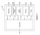
- FIG. 2is a schematic view of an illustrative HVAC controller 18 .
- HVAC controller 18may be a thermostat, but this is not required.
- HVAC controller 18includes a controller (e.g. microprocessor, microcontroller, etc.) 44 , a user interface 48 , a memory 52 , and a timer 54 .
- the timer 54may be integral to the controller 44 or may be provided as a separate component.
- the HVAC controller 18may optionally include an input/output block (I/O block) 58 for receiving one or more signals from the HVAC system 4 and/or for providing one or more control signals to the HVAC system 4 .
- I/O blockinput/output block
- the I/O block 58may communicate with one or more HVAC components 6 of the HVAC system 4 . Additionally, in some cases, the I/O block 58 may communicate with another controller, which is in communication with one or more HVAC components 6 of the HVAC system 4 , such as a zone control panel in a zoned HVAC system, equipment interface module (EIM) 34 or any other suitable building control device.
- the I/O block 58may communicate with another controller, which is in communication with one or more HVAC components 6 of the HVAC system 4 , such as a zone control panel in a zoned HVAC system, equipment interface module (EIM) 34 or any other suitable building control device.
- EIMequipment interface module
- the controller 44may operate in accordance with an algorithm that controls or at least partially controls one or more HVAC components 6 of an HVAC system such as, for example, HVAC system 4 shown in FIG. 1 .
- the controller 44may, for example, operate in accordance with an algorithm that provides temperature set points, starting and/or ending times, and the like.
- the controller 44may be configured to read a temperature sensed by the temperature sensor and control the one or more HVAC components 6 of the HVAC system 4 in to maintain a desired temperature set point within the building 2 in accordance with a programmable schedule stored in the memory 52 of the HVAC controller 18 .
- the controller 44may be configured to control the one or more HVAC components 6 including one or more indoor air quality units such as, for example a ventilation unit, a humidification unit, and/or a dehumidification unit, to maintain a desired indoor air quality within the building 2 , sometimes in accordance with a programmable schedule stored in the memory 52 of the HVAC controller 18 .
- indoor air quality unitssuch as, for example a ventilation unit, a humidification unit, and/or a dehumidification unit
- the controller 44may be programmed to control the one or more indoor air quality units according to a programmable operating schedule that includes one or more time periods.
- the programmable operating schedulemay include the same time period as the programmable operating schedule of the temperature setpoints (heating and/or cooling setpoints), or they may be different time periods. In either case,
- the controller 44may be programmed to allow a user to select at least a first time period of the programmable operating schedule to control at least one of the one or more indoor air quality units (e.g. ventilation unit, humidifier unit, dehumidifier unit) differently than during at least one other of time period of the programmable operating schedule.
- the one or more indoor air quality unitse.g. ventilation unit, humidifier unit, dehumidifier unit
- the controller 44may be programmed to allow a user to select a time period in which an indoor quality unit will operate and a different time period in which the indoor air quality unit will not operate (or will operate in a different mode, at a different speed, at a different setpoint, or at some other different setting).
- the controller 44may be programmed to allow a user to select which indoor air quality units will or will not operate during each time period of the programmable operating schedule, and/or during a user's vacation schedule.
- the controller 44may be programmed to allow a user to select which indoor air quality units may operate at a reduced level to conserve energy while at the same time maintaining indoor air quality for a period of time identified by the user such as, for example, the user's vacation schedule.
- user interface 48may be any suitable user interface that permits HVAC controller 18 to display and/or solicit information, as well as accept one or more user interactions with the HVAC controller 18 .
- the user interface 48may permit a user to enter data such as temperature set points, humidity set points, starting times, ending times, diagnostic limits, conditions under which diagnostic limits may be suspended, responses to alerts, requests for ventilation, and/or the like.
- the HVAC controller 18may be configured to receive and accept a user's input that identifies at least one time period in which one or more indoor air quality units will not operate, or will operate in a different mode, at a different speed, at a different setpoint, or at some other different setting.
- the at least one time period identified by the user in which one or more indoor air quality units may not operatemay correspond to one of the time periods of a programmable temperature set point operating schedule.
- the at least one time period identified by the user in which one or more indoor air quality units may operate in a different mode or may not operatemay correspond to a user's vacation time period.
- user interface 48may include a display and a distinct keypad.
- a displaymay be any suitable display.
- a displaymay include or may be a liquid crystal display (LCD), and in some cases a fixed segment display or a dot matrix LCD display.
- user interface 48may be a touch screen LCD panel that functions as both display and keypad.
- a touch screen LCD panelmay be adapted to solicit values for a number of operating parameters and/or to receive such values, but this is not required.
- the memory 52 of the illustrative HVAC controller 18may be in communication with the controller 44 .
- Memory 52may be used to store any desired information, such as the aforementioned control algorithm, set points, schedule times, diagnostic limits such as, for example, differential pressure limits, delta T limits, and the like.
- Memory 52may be any suitable type of storage device including, but not limited to, RAM, ROM, EPROM, flash memory, a hard drive, and/or the like.
- controller 44may store information within memory 52 , and may subsequently retrieve the stored information.
- HVAC controller 18may include a data port 56 .
- Data port 56may be a wireless port such as a BluetoothTM port or any other wireless protocol.
- data port 56may be a wired port such as a serial port, a parallel port, a CATS port, a USB (universal serial bus) port, and/or the like.
- data port 56may be a USB port and may be used to download and/or upload information from a USB flash drive or some other data source. Other remote devices may also be employed, as desired.
- Data port 56may be configured to communicate with controller 44 and may, if desired, be used to upload information to controller 44 and/or download information from controller 44 .
- Information that can be uploaded and/or downloadedmay include, for example, values of operating parameters.
- data port 56may be used to upload a previously-created thermostat configuration into HVAC controller 18 , thereby hastening the programming process.
- data port 56may be used to download a thermostat configuration that has been created using HVAC controller 18 , so that the thermostat configuration may be transferred to other similar thermostats, hastening their programming process.
- data port 56may be used to upload and/or download information pertaining to an HVAC dealer or contractor, if desired.
- data port 56may be used to download data stored within the memory 52 for analysis.
- data port 56may be used to download a faults and/or alerts log or parts thereof to a remote device such as a USB memory stick (also sometimes referred to as a thumb drive or jump drive), personal computer, laptop, iPAD® or other tablet computer, PDA, smart phone, or other remote device, as desired.
- a remote devicesuch as a USB memory stick (also sometimes referred to as a thumb drive or jump drive), personal computer, laptop, iPAD® or other tablet computer, PDA, smart phone, or other remote device, as desired.
- the datamay be convertible to an MS EXCEL®, MS WORD®, text, XNL, and/or Adobe PDF® file, but this is certainly not required.
- FIG. 3is a front view of an illustrative HVAC controller 18 .
- HVAC controller 18may be configured to provide substantial display and/or programming functionality.
- HVAC controller 18may include a display 62 that is disposed within a housing 66 but viewable externally from the housing 66 .
- display 62may be a touch screen LCD display.
- display 62may be a dot matrix touch screen LCD display.
- a dot matrix touch screen LCD displayis a touch screen LCD that permits images such as letters, numbers, graphics, images, and the like to be displayed anywhere on the LCD, rather than being confined to predetermined locations such as is the case with a fixed segment type of LCD display.
- Housing 66may be formed of any suitable material, such as a polymeric material. In some cases, the housing 66 may be formed such that it defines a data port 56 (see FIG. 2 ). In some cases, the housing 66 may also include suitable wiring and/or other electrical connections 68 such that the HVAC controller 18 may be electrically coupled to the HVAC system 4 , but this is not required.
- FIGS. 4-24show several illustrative screens that maybe displayed on the display 62 of the HVAC controller 18 of FIGS. 2 and 3 when in use.
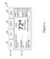
- FIG. 4shows an illustrative home screen 72 that may be displayed on the display 62 of an HVAC controller 18 .
- Home screen 72is an example of a screen that may be displayed after a user has pushed HOME button 78 , or when no other data entry is underway for a period of time.
- the illustrative home screen 72 of FIG. 4may include a navigational bar 76 along the top. Navigational bar 76 may be considered as providing top level navigation.
- navigational bar 76may include one or more of a HOME button 78 , a FAN button 80 , a SYSTEM button 82 and/or a MENU button 84 .
- the usermay access one or more menus from which the user may make a temperature set point change, a humidity set point change, an indoor air quality change, a programmable schedule change, a system mode change, a fan setting change, an installer set-up change, an exit/entry remote setting change, among others.
- FIG. 5shows an illustrative example of a menu screen 100 that may be displayed when a user selects the MENU button 84 on home screen 72 of FIG. 4 .
- the illustrative menu screen 100may include a table 104 that includes one or more selectable menu options 108 a - d that may be selected by the user.
- the table 104may be a scrolling table, in which case the menu screen 100 may also include a scroll bar 112 including first and second arrows 116 a , 116 b that may facilitate a user in scrolling through the available menu options 108 - d .
- a first option 108 amay be labeled “Humidification” and may correspond to the humidification settings for the HVAC system 4
- a second option 108 bmay be labeled “Dehumidification” and may correspond to the dehumidification settings for the HVAC system
- a third option 108 cmay be labeled “Ventilation” and may correspond to the ventilation settings for the HVAC system
- a fourth option 108 dmay be labeled “Vacation Mode” and may correspond to a vacation mode of the HVAC system 4 .
- FIGS. 6-7show several illustrative screens that may be displayed on the display 62 of the HVAC controller 18 in response to a user having selected the first option 108 a labeled “Humidification.”
- FIG. 6shows a first humidification settings screen 150 through which a user may select and/or set a humidification setting.
- HVAC controller 18may, for example, use the humidification setting in controlling a humidifier such as a whole-house humidifier.
- HVAC controller 18may, for example, display a parameter adjustment element for use in adjusting an operating parameter such as a humidity set point.
- the parameter adjustment elementmay include an indicator that provides a qualitative indication for at least the current setting of the operating parameter. For example, as shown in the illustrative example provided in FIG.
- screen 150includes a slider bar 154 that has a scale 158 , a display 160 , and first and second arrows 162 a , 162 b .
- Scale 158can be seen as including text describing the humidity setting in relative or qualitative terms such as “Dry” and “Comfort Zone.” These particular terms are merely representative, as other terms may also be used. More generally, scale 158 may provide a qualitative context to a particular humidity value (e.g. 42%) so that a user unfamiliar with humidity values can still choose an appropriate humidity setting.
- Display 160may, as illustrated, provide a reminder that it is the indoor humidity setting that is being displayed as well as a current indoor humidity setting or current indoor humidity reading.
- Slider bar 154may be seen as including an indicator button 164 that may be moved left and/or right using first and second arrow keys 162 a , 162 b , as desired.
- Indicator button 164may, with respect to scale 158 , provide a visual indication of the relative or qualitative humidity setting and may, if desired, include a pointer 166 that interacts with scale 158 .
- Scale 158may also provide upper and/or lower numerical limits for the displayed parameter, but this is not required.
- indicator button 164may include a numerical representation (quantitative value) of the indoor humidity setting.
- Screen 150may also indicate a current humidification status in a first region 170 and a current operational setting in a second region 174 .
- the current humidification statusis indicated as “humidifying”, and the current operational setting is indicated as “auto” (i.e. automatic).
- screen 150may include a Help button 182 , a Cancel button 186 , and a Done button 190 .
- Help button 182when selected, may cause HVAC controller 18 to display further information explaining humidification, providing clarification regarding screen options, and the like.
- Cancel button 186when selected, may cause HVAC controller 18 to display a previous screen such as, for example menu screen 100 of FIG. 5 .
- Done button 190when selected, may inform HVAC controller 18 that the humidification setting has been completed, and as a result, may display menu screen 100 ( FIG. 5 ) or, in some cases, home screen 72 ( FIG. 4 )
- Screen 150may also include a button 194 labeled “More Settings” or “Advanced Settings,” that, when selected, may cause HVAC controller 18 to display a second humidification settings screen 200 , such as shown in FIG. 7 .
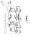
- screen 200may include a user prompt 204 that may prompt a user to select one or more time periods of a programmable operating schedule in which humidification may be turned off and a humidifier unit will not operate.
- a usermay desire to turn off humidification or operate a humidification unit at a reduced level for energy conservation during certain periods due to noise of operation, energy costs during peak demand times, and/or according to user preference.
- screen 200may include a one or more individually selectable options 208 a - 208 d , each option 208 a - 208 d corresponding to a time period of an operating schedule of the HVAC system 4 stored in the controller memory 52 of HVAC controller 18 .
- the operating schedulemay correspond to the programmable schedule that is used to control the temperature set points of the HVAC controller 18 .
- the operating schedulemay be a separately programmed schedule from the programmable schedule that is used to control the temperature set points of the HVAC controller 18 .
- screen 200includes a first option 208 a corresponding to a Wake period of the programmable schedule that is used to control the temperature set points of the HVAC controller 18 .
- Screen 200also include a second option 208 b corresponding to a Leave period, a third option 208 c corresponding to a Return period, and a fourth option 208 d corresponding to a Sleep period.
- the options 208 a - 208 d that may be displayed for selection by the usermay be dependent on the operating schedule stored in the controller memory 52 . It will be understood that fewer or more selectable options 208 a - 208 d may be displayed corresponding to the number of time periods as determined by the programmable schedule.
- identifiers and/or labelsmay be used to identify each of the different time periods available for selection.
- a first optionmay correspond to Period 1
- a second optionmay correspond to Period 2
- third optionmay correspond to Period 3, and so on.
- a usermay select a least one (or more) of the displayed options 208 a - 208 d , each of the different options 208 a - 208 d corresponding to a different one of the time periods of the operating schedule. Selection of one option may not affect selection of another subsequent option.
- Each of the options 208 a - 208 dmay include a selection indicator box 212 that, when selected by a user, may include a checkmark, an X, may be filled in, greyed out, or otherwise highlighted to indicate selection of that option.
- second 208 b corresponding to the Leave time period of the operating schedule stored in the memory 52 of the HVAC controller 18includes a check mark 214 indicating selection.
- humidificationwill continue during the time periods that correspond to the non-selected options, and humidification will be turned off or otherwise discontinued during the time periods that correspond to the selected option(s).
- humidificationwill continued during the Wake, Return and Sleep time periods of the schedule stored in the controller memory 52 , but will be turned off during the Leave time period.
- screen 200may include an option 216 that, when selected, may cause HVAC controller 18 to turn off the humidifier unit.
- option 216may have a toggle feature such that, when selected again, the HVAC controller 18 may enable humidification.
- Screen 200may also include a Help button 220 , a Back button 224 , and a Done button 228 .
- Help button 220when selected, may cause HVAC controller 18 to display further information explaining humidification, providing clarification regarding options, and the like.
- Back button 224when selected, may cause HVAC controller 18 to display a previous screen such as, for example menu screen 100 of FIG. 5 .
- Done button 228when selected, may informs HVAC controller 18 that the humidification setting has been completed, and as a result, HVAC controller 18 may display menu screen 100 ( FIG. 5 ) or, in some cases, home screen 72 ( FIG. 4 ). While screen 200 shows an example where that allows a user to select those time periods when the humidifier unit will not operate, it should be understood that a similar screen may be provided that allows a user to select those time period when the humidifier unit will be enabled and may operate.
- FIG. 8shows a first dehumidification settings screen 250 through which a user may select and/or set a dehumidification setting.
- HVAC controller 18may, for example, use the dehumidification setting to control a dehumidifier such as a whole-house dehumidifier.
- HVAC controller 18may, for example, display a parameter adjustment element for use in adjusting an operating parameter such as dehumidification, the parameter adjustment element may include an indicator that provides a qualitative indication for at least the current setting of the operating parameter.
- screen 250includes a slider bar 254 that has a scale 258 , a display 260 , and first and second arrows 262 a , 262 b .
- Scale 258can be seen as including text describing the humidification setting in relative or qualitative terms such as “Wet” and “Comfort Zone”. These particular terms are merely representative, as other terms may also be used. More generally, scale 258 may provide a qualitative context to a particular humidity value (e.g. 55%) so that a user unfamiliar with humidity values can still choose an appropriate humidity setting.
- Display 260may, as illustrated, provide a reminder that it is the indoor humidity setting that is being displayed as well as a current indoor humidity setting or current indoor humidity reading.
- Slider bar 254may be seen as including an indicator button 264 that may be moved left and/or right using first and second arrow keys 262 a , 262 b , as desired.
- Indicator button 264may, with respect to scale 258 , provide a visual indication of the relative or qualitative humidity setting and may, if desired, include a pointer 266 that interacts with scale 258 .
- Scale 258may also provide upper and/or lower numerical limits for the displayed parameter, but this is not required.
- indicator button 264may include a numerical representation (quantitative value) of the indoor humidity setting.
- Screen 250may also indicate a current dehumidification status in a first region 270 and a current operational setting in a second region 274 .
- the current dehumidification statusis indicated as “dehumidifying” and the current operational setting is indicated as “auto” (i.e. automatic).
- screen 250may include a Help button 282 , a Cancel button 286 , and a Done button 290 .
- Help button 282when selected, may cause HVAC controller 18 to display further information explaining dehumidification, providing clarification regarding options, and the like.
- Cancel button 286when selected, may cause HVAC controller 18 to display a previous screen such as, for example menu screen 100 of FIG. 5 .
- Done button 290when selected, may inform HVAC controller 18 that the dehumidification setting has been completed, and as a result, may display menu screen 100 ( FIG. 5 ) or, in some cases, home screen 72 ( FIG. 4 ).
- Screen 250may also include a button 294 labeled “More Settings” or “Advanced Settings,” that when selected, may cause HVAC controller 18 to display a second dehumidification settings screen 300 , such as shown in FIG. 9 .
- screen 300may include a user prompt 304 that may prompt a user to select one or more time periods in which the dehumidification unit may be turned off and will not operate.
- a usermay desire to turn off the dehumidification unit or operate the dehumidification unit at a reduced level for energy conservation during certain periods due to noise of operation, energy costs during peak demand times, and/or according to user preference.
- screen 300may include a one or more individually selectable options 308 a - 308 d , each option 308 a - 308 d corresponding to a time period of an operating schedule of the HVAC system 4 stored in the controller memory 52 of HVAC controller 18 .
- screen 300includes a first option 308 a corresponding to a Wake period, a second option 308 b corresponding to a Leave period, a third option 308 c corresponding to a Return period, and a fourth option 308 d corresponding to a Sleep period.
- the options 308 a - 308 d that may be displayed for selection by the usermay be dependent of the operating schedule stored in the controller memory 52 .
- selectable options 308 a - 308 dmay be displayed corresponding to the number of time periods as determined by the schedule. It will also be understood that different identifiers and/or labels may be used to identify each of the different time periods available for selection. For example, in some cases, a first option may correspond to Period 1, a second option may correspond to Period 2, and third option may correspond to Period 3, and so on. These are just some examples.
- a usermay select a least one of the displayed options 308 a - 308 d , each of the different options 308 a - 308 d corresponding to a different time period of the schedule. Selection of one option may not affect selection of another subsequent option.
- Each of the options 308 a - 308 dmay include a selection indicator box 312 that, when selected by a user, may include a checkmark, an X, may be filled in, greyed out, or otherwise highlighted to indicate selection of that option.
- fourth option 308 bcorresponding to the Sleep time period of the operating schedule stored in the memory 52 of the HVAC controller 18 , includes a check mark 314 indicating selection.
- the dehumidification unitwill continue operating according to a dehumidification setting during the time periods corresponding to the non-selected options, and the dehumidification unit will be turned off or otherwise discontinued during the time periods corresponding to the selected options. For example, according to the illustrative example shown in FIG. 9 , the dehumidification unit will continue operating according to the dehumidification setting(s) during the Wake, Return and Leave time periods of the schedule stored in the controller memory 52 , but will be turned off during the Sleep time period.
- screen 300may include an option 316 for disabling dehumidification that, when selected, may cause HVAC controller 18 to turn off the dehumidification unit regardless of time period.
- option 316may have a toggle feature such that, when selected again, may cause HVAC controller 18 to resume operating of the dehumidification.
- Screen 300may also include a Help button 320 , a Back button 324 , and a Done button 328 .
- Help button 320when selected, may cause HVAC controller 18 to display further information explaining dehumidification, providing clarification regarding options, and the like.
- Back button 324when selected, may cause HVAC controller 18 to display a previous screen such as, for example menu screen 100 of FIG. 5 .
- Done button 328when selected, may inform HVAC controller 18 that the dehumidification setting has been entered, and as a result, HVAC controller 18 may display menu screen 100 ( FIG. 5 ) or, in some cases, home screen 72 ( FIG. 4 ).
- screen 300shows an example where that allows a user to select those time periods when the dehumidifier unit will not operate, it should be understood that a similar screen may be provided that allows a user to select those time period when the dehumidifier unit will be enabled and may operate.
- FIG. 10provides an example of a first ventilation settings screen 350 .
- ventilation settings screen 350may include a first region 354 that may identify the current ventilation setting (e.g. automatic) and/or a current ventilation status (e.g. ventilating).
- Ventilation control screen 350may also provide one or more selectable options for requesting and/or cancelling a ventilation boost in a second region 358 .
- the second region 358 of ventilation settings screen 350includes a box 360 that may display a temporary ventilation boost time 364 , and first and second arrows 366 a , 366 b for increasing or decreasing the temporary ventilation boost time 364 displayed in the box 360 .
- the temporary ventilation boost time 364may be increased or decreased in increments of 5, 10, 15, or 20 minutes using the first and second arrow keys 366 a , 366 b .
- Second region 358may also include an additional selectable option 368 for cancelling the temporary ventilation boost request received via ventilation control screen 350 and/or ventilation boost requests received from one or more remotely located ventilation boost control units (if provided).
- Ventilation settings screen 350also may include a Cancel or Back button 372 , a Help button 376 , and a Done button 380 .
- Cancel button 372when selected, may cause HVAC controller 18 to display a previous screen such as, for example menu screen 100 of FIG. 5 .
- Help button 376when selected, may cause HVAC controller 18 to display further information explaining ventilation, providing clarification regarding screen options, and the like.
- Done button 380when selected, may inform HVAC controller 18 that the ventilation setting has been completed, and as a result, HVAC controller 18 may display menu screen 100 ( FIG. 5 ) or, in some cases, home screen 72 ( FIG. 4 ).
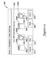
- ventilation settings screen 350may also include a Next button 388 . Selection of the Next button 388 may cause HVAC controller 18 to display an additional ventilation settings screen, such as ventilation setting screen 400 of FIG. 11 .
- ventilation settings screen 400may display one or more ventilation options 404 corresponding to one or more different operating modes for the ventilation unit. For example, screen 400 may display a first option 404 a labeled “Automatic” and corresponding to an automatic operating mode for the ventilation unit, a second option 404 b labeled “Off” and corresponding to an “off” mode for the ventilation unit, and a third option 404 c labeled “ON (High)” and corresponding to an “on” mode for the ventilation unit with the fan speed set at high.
- the options 404may be displayed in a table 408 .
- additional options corresponding to additional operating modes of the ventilation unitmay be provided in which case table 408 may be a scrollable table 408 and may include a scroll bar 412 having first and second arrow keys 416 a , 416 b for navigating the table 408 .
- table 408may be a scrollable table 408 and may include a scroll bar 412 having first and second arrow keys 416 a , 416 b for navigating the table 408 .
- another option labeled “ON (Low)”may be provided that corresponds to an “on” mode for the ventilation unit with the fan speed set at low.
- Another option labeled “Intermittent”may be provided that corresponds to turning the ventilation unit on for approximately 20 minutes of every hour.
- Ventilation settings screen 400also may also include a Cancel or Back button 420 , a Help button 424 , and a Done button 428 .
- Cancel button 420when selected, may cause HVAC controller 18 to display a previous screen such as, for example menu screen 100 of FIG. 5 .
- Help button 424when selected, may cause HVAC controller 18 to display further information explaining ventilation, providing clarification regarding screen options, and the like.
- Done button 428when selected, may inform HVAC controller 18 that the ventilation setting has been completed, and as a result, may display menu screen 100 ( FIG. 5 ) or, in some cases, home screen 72 ( FIG. 4 ).
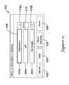
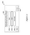
- ventilation settings screen 400may also include a button 432 labeled “More Settings” or “Advanced Settings”. Selection of the button 432 may cause HVAC controller 18 to display another screen, such as 450 of FIG. 12 .
- screen 450may include a user prompt 454 which may prompt a user to select one or more time periods in which a ventilation unit may be turned off and will not operate. A user may desire to turn off the ventilation unit or operate the ventilation unit at a reduced level for energy conservation during certain periods due to noise of operation, high energy costs during peak demand times, and/or according to user preference.
- screen 450may include a one or more individually selectable options 458 a - 458 d , each option 458 a - 458 d corresponding to a time period of an operating schedule of the HVAC system 4 stored in the controller memory 52 of HVAC controller 18 .
- screen 450may include a first option 458 a corresponding to a Wake period, a second option 458 b corresponding to a Leave period, a third option 458 c corresponding to a Return period, and a fourth option 458 d corresponding to a Sleep period.
- the options 458 a - 458 d that may be displayed for selection by the usermay be dependent on the operating schedule stored in the controller memory 52 .
- selectable options 458 a - 348 dmay be displayed corresponding to the number of time periods as determined by the schedule. Additionally, it will be understood that different identifiers and/or labels may be used to identify each of the different time periods available for selection. For example, in some cases, a first option may correspond to Period 1, a second option may correspond to Period 2, and third option may correspond to Period 3, and so on. These are just some examples.
- a usermay select a least one of the displayed options 458 a - 458 d , each of the different options 458 a - 458 d corresponding to a different time period of the schedule. Additionally, selection of one option may not affect selection of another subsequent option.
- Each of the options 458 a - 458 dmay include a selection indicator box 462 that, when selected by a user, may include a checkmark (shown), an X, may be filled in, greyed out, or otherwise highlighted to indicate selection of that option.
- second option 458 b corresponding to the Leave time period and fourth option 458 d corresponding to the Sleep time period of the operating schedule stored in the memory 52 of the HVAC controller 18include a check mark 464 indicating selection.
- the ventilation unitwill continue operating according to a ventilation setting (e.g. automatic, on (high), on (low), Intermittent) during the time periods corresponding to the non-selected options, and the ventilation unit will be turned off or otherwise discontinued during the time periods corresponding to the selected options.
- a ventilation settinge.g. automatic, on (high), on (low), Intermittent
- the ventilation unitwill continue operating according to the ventilation setting during the Wake and Return time periods of the schedule stored in the controller memory 52 , but will be turned off during the Leave and Sleep time periods.
- Screen 450may also include a Help button 470 , a Cancel or Back button 474 , and a Done button 478 .
- Help button 470when selected, may cause HVAC controller 18 to display further information explaining ventilation, providing clarification regarding screen options, and the like.
- Cancel button 474when selected, may cause HVAC controller 18 to display a previous screen such as, ventilation settings screen 400 of FIG. 11 or screen 350 of FIG. 10 .
- Done button 478when selected, may inform HVAC controller 18 that the ventilation setting has been completed, and as a result, HVAC controller 18 may display menu screen 100 ( FIG. 5 ) or, in some cases, home screen 72 ( FIG. 4 ). While screen 450 shows an example where that allows a user to select those time periods when the ventilation unit will not operate, it should be understood that a similar screen may be provided that allows a user to select those time period when the ventilation unit will be enabled and may operate.
- screen 450may also include a Next button 482 that, when selected may cause HVAC controller to display another ventilation settings screen, such as additional ventilation setting screen 500 shown in FIG. 13 .
- ventilation settings screen 500may include a user prompt 504 that may prompt a user to active or deactivate a ventilation lockout feature during periods of high outdoor humidity.
- ventilation settings screen 500may display a first option 508 labeled “Off” for deactivating a ventilation lockout, and a second option 510 labeled “On” for activating a ventilation lockout during periods of high outdoor humidity. Selection of the first option 508 labeled “Off” will cause the HVAC controller 18 to not deactivate the ventilation unit when the outdoor humidity rises above a threshold humidity value. Selection of the second option 510 labeled “On” will cause the HVAC controller 18 to deactivate the ventilation unit when the outdoor humidity rises above a threshold humidity value.
- Screen 500may also include a Help button 514 , a Cancel or Back button 518 , and a Done button 522 .
- Help button 514when selected, may cause HVAC controller 18 to display further information explaining ventilation lockouts, providing clarification regarding screen options, and the like.
- Back button 518when selected, may cause HVAC controller 18 to display a previous screen such as, for example, ventilation settings screen 450 of FIG. 12 .
- Done button 522when selected, may inform HVAC controller 18 that the ventilation setting has been completed, and as a result, HVAC controller 18 may display menu screen 100 ( FIG. 5 ) or, in some cases, home screen 72 ( FIG. 4 ).
- selection of the fourth menu option 108 d labeled “Vacation Mode”may cause HVAC controller 18 to display a sequence of one or more screens, such as shown in FIGS. 14-24 , that may guide a user through designating different parameters and operational modes to be maintained during an extended period of time in which a user may be away from the building (e.g. vacation).
- FIG. 14displays a first screen 530 of a sequence of screens related to a vacation mode of the HVAC controller 18 .
- First screen 530may include a user prompt 532 that may prompt a user to set the date on which their vacation period will begin. As shown in FIG.
- first screen 530includes a first box 534 including first and second arrow keys 536 a , 536 for selecting the month a second box 538 including first and second arrow keys 540 a , 540 b for selecting the day on which the vacation period will begin.
- First screen 530may also display the current date in a region 542 above or below the first and second boxes 534 , 538 .
- screen 530may include a Cancel or Back button 542 and a Next button 544 .
- Cancel button 542when selected, may cause HVAC controller 18 to display a previous screen such as, for example, menu screen 100 of FIG. 5 .
- Selection of the Next button 544may cause HVAC controller 18 to display a next screen 550 in the sequence of screens related to the vacation mode of the HVAC system, such as shown in FIG. 15 .
- Screen 550may include a user prompt 552 that may prompt the user to set the time at which the vacation period will begin. As shown in FIG. 15 , screen 550 may include a box 554 displaying a time and first and second arrow keys 556 a , 556 b , for adjusting the time displayed in the box 554 to the time at which the vacation period will begin. In addition, screen 550 may include a Back button 558 that, when selected, may cause HVAC controller 18 to display the previous screen (e.g. screen 530 of FIG. 14 ). Screen 550 also may include a Next button 560 that, when selected, may cause HVAC controller 18 to display the next screen 562 in the sequence of screens related to the vacation mode of the HVAC system, such as shown in FIG. 16 .
- a Back button 558that, when selected, may cause HVAC controller 18 to display the previous screen (e.g. screen 530 of FIG. 14 ).
- Screen 550also may include a Next button 560 that, when selected, may cause HVAC controller 18 to display the next screen
- FIG. 16shows an illustrative example of a screen 562 that may be displayed on the display 62 of HVAC controller 18 through which a user may select which operational mode of the HVAC system is to be maintained during the user's vacation period.
- screen 562may include a user prompt that may prompt the user to select an operating mode of the HVAC system to maintain during the user's vacation period.
- Screen 562may display one or more options 564 a - 564 c , each option 564 a - 564 c corresponding to an available operational mode for the HVAC system 4 .
- screen 562may display a first option 564 a corresponding to a heating mode, a second option 564 b corresponding to a cooling mode, and a third option 564 c corresponding to an automatic mode.
- the selected optionmay be bolded, greyed out, include a different border, or otherwise highlighted to indicate selection by the user.
- the second option 564 b corresponding to the cooling modeis bolded indicating selection by the user.
- the usermay select the Next button 568 to advance to a next screen 570 within the sequence of screens related to the vacation mode, such as shown in FIG. 17 .
- FIG. 17provides an illustrative example of a screen 570 through which a user may enter and set a temperature to be maintained during the vacation time period.
- Screen 570may include a user prompt 572 that may prompt the user to adjust and set a temperature set point to be maintained while away on vacation.
- screen 570may include a box 574 that displays a temperature corresponding to the operating mode selected through the previous screen (e.g. screen 562 of FIG. 16 ), and first and second arrow keys 556 a , 556 b for adjusting the temperature displayed in the box 574 .
- Selection of the Next button 578may cause HVAC controller 18 to accept the temperature set point entered by the user in box 574 , and may cause HVAC controller 18 to display yet another screen 580 in the sequence of screens related to the vacation mode of the HVAC system 4 , such as shown in FIG. 18 .
- FIG. 18provides an example of a screen 580 that may be displayed on the display 62 of HVAC controller 18 through which a user may select a fan mode to be maintained during the user's vacation period.
- screen 580may include a user prompt 582 that may prompt the user to select a fan mode to be maintained during the vacation.
- Screen 580may display one or more selectable options 584 a - 584 c , each option 584 a - 584 c corresponding to an available fan mode for the HVAC system 4 .
- the one or more selectable options 584 a - 584 cmay be displayed in a table 586 .
- Table 586may be a scrollable table in which case a scroll bar 587 including first and second arrow keys 588 a , 588 b may be provided for navigating the different options corresponding to each of the available fan modes displayed in table 586 .
- screen 580may display an additional fan option 590 for following a predetermined fan mode schedule stored in the controller memory 52 of HVAC controller 18 , but this is not required.
- the selected optionmay be bolded, greyed out, include a different border, or otherwise highlighted to indicate selection by the user.
- the second option 584 b corresponding to an automatic fan modeis bolded indicating selection by the user.
- the usermay select the Next button 594 to advance to another screen 600 within the sequence of screens related to the vacation mode, such as shown in FIG. 19 .
- FIG. 19shows an example of a screen 600 that may be displayed on the display 62 of HVAC controller 18 through which a user may select one or more operations for maintaining the indoor air quality within the building 2 during the vacation period.
- screen 600includes a user prompt 602 that prompts the user to select which indoor air quality operations are to be maintained while the user is away on vacation.
- Screen 600may display one or more individually selectable options 604 a - 604 c , each option 604 a - 604 c corresponding to an available indoor air quality operation of the HVAC system 4 .
- screen 600may display a first option 604 a corresponding to humidification, a second option 604 b corresponding to dehumidification, and a third option 604 c corresponding to ventilation.
- only the indoor air quality operations corresponding to the indoor air quality units included in the HVAC system 4may be displayed. For example, if the HVAC system 4 does not include a dehumidifier unit, an option corresponding to dehumidification may not be displayed.
- a usermay select zero or more of the displayed options 604 a - 604 c , each of the different options 604 a - 604 c corresponding to a different indoor air quality operation of the HVAC system 4 .
- selection of one optionmay not affect selection of another subsequent option.
- Each of the options 604 a - 604 cmay include a selection indicator box 606 that, when selected by a user, may include a checkmark, an X, may be filled in, greyed out, or otherwise highlighted to indicate selection of that option.
- first option 604 a corresponding to humidification and third option 604 c corresponding to ventilationeach include a check mark 608 indicating selection.
- the HVAC system 4will operate the humidification and ventilation units according to a vacation mode or setback mode in which the HVAC system 4 may maintain humidification and ventilation at reduced levels to conserve energy. Dehumidification of the building 2 may continue as normal. Selection of the Next button 610 may cause HVAC controller 18 to display another screen 614 within the sequence of screens related to the vacation mode, such as shown in FIG. 20 .
- screen 614may include a user prompt 618 that may prompt a user to set the date on which their vacation period will end.
- Screen 614may have a first box 620 including first and second arrow keys 622 a , 622 b for selecting the month, and a second box 624 including first and second arrow keys 628 a , 628 b for selecting the day on which the vacation period will end.
- Screen 614may also display the current date in a region 632 above or below the first and second boxes 620 , 624 .
- Selection of the Next button 636may cause HVAC controller 18 to display the next screen 640 in the sequence of screens related to the vacation mode of the HVAC system, such as shown in FIG. 21 .
- screen 640may include a user prompt 642 that may prompt the user to set the time at which the vacation period will end. Additionally, screen 640 may include a box 644 displaying a time and first and second arrow keys 646 a , 646 b for adjusting the time displayed in the box 644 . Screen 644 also may include a Next button 648 that, when selected, may cause HVAC controller to accept the time entered by the user, and to display another screen 660 in the sequence of screens related to the vacation mode of the HVAC system, such as shown in FIG. 22 .
- FIG. 22shows an example screen 660 that may be displayed on the display 62 of HVAC controller 18 through which a user may select which operational mode of the HVAC system 4 to be maintained upon the user's return at the end of the vacation period.
- screen 660may include a user prompt 662 that may prompt the user to select an operating mode of the HVAC system to be maintained upon the user's return.
- Screen 660may display one or more options 664 a - 664 c , each option 664 a - 664 c corresponding to an available operational mode for the HVAC system 4 .
- screen 660may display a first option 664 a corresponding to a heating mode, a second option 664 b corresponding to a cooling mode, and a third option 664 c corresponding to an automatic mode.
- the selected optionmay be bolded, greyed out, include a different border, or otherwise highlighted to indicate selection by the user.
- the second option 664 b corresponding to the cooling modeis bolded indicating selection by the user.
- the usermay select the Next button 668 to advance to the next screen 670 within the sequence of screens related to the vacation mode, such as shown in FIG. 23 .
- FIG. 23provides an illustrative example of a screen 670 through which a user may enter and set a temperature to be maintained upon their return at the end of the vacation period.
- Screen 670may include a user prompt 672 that may prompt the user to adjust and set a temperature set point to be maintained upon the user's return.
- screen 670may include a box 674 displaying a temperature corresponding to the operating mode selected through the previous screen (e.g. screen 660 of FIG. 22 ) and first and second arrow keys 676 a , 676 b for adjusting the temperature displayed in the box 674 to the user's desired temperature.
- Selection of the Next button 678may cause HVAC controller 18 to accept the temperature set point entered by the user, and cause HVAC controller 18 to display yet another screen 680 in the sequence of screens related to the vacation mode of the HVAC system 4 , such as shown in FIG. 24 .
- FIG. 24provides an illustrative example of a summary screen 680 through which a user may review the settings related to the vacation period.
- the information displayed on the summary screen 680may be in any suitable format.
- the summary page shown in FIG. 24is just one example. If the data displayed on the summary screen 680 is acceptable to the user, the user may select Done button 682 . Selection of Done button 682 may cause the HVAC controller 18 to accept each of the different operational settings corresponding to the vacation period, and may cause HVAC controller 18 to display home screen 72 as shown in FIG. 4 . If any of the settings are not acceptable to the user, the user may user Back button 684 to navigate back through the sequence of screens discussed above to the appropriate screen or screens, making any adjustments as necessary or desired.
- screens 562 , 570 , 580 , 600 , 614 , 640 , 660 , and 670generally relate to a cooling mode of the HVAC system 4 , it will be understood that a similar set of screens may be displayed on the display 62 of HVAC controller 18 related to the heating mode or automatic mode.
Landscapes
- Engineering & Computer Science (AREA)
- General Engineering & Computer Science (AREA)
- Chemical & Material Sciences (AREA)
- Combustion & Propulsion (AREA)
- Mechanical Engineering (AREA)
- Signal Processing (AREA)
- Physics & Mathematics (AREA)
- Fuzzy Systems (AREA)
- Mathematical Physics (AREA)
- Human Computer Interaction (AREA)
- Fluid Mechanics (AREA)
- General Physics & Mathematics (AREA)
- Automation & Control Theory (AREA)
- Air Conditioning Control Device (AREA)
Abstract
Description
Claims (18)
Priority Applications (3)
| Application Number | Priority Date | Filing Date | Title |
|---|---|---|---|
| US13/403,878US9810441B2 (en) | 2012-02-23 | 2012-02-23 | HVAC controller with indoor air quality scheduling |
| US15/786,420US10900682B2 (en) | 2012-02-23 | 2017-10-17 | HVAC controller with indoor air quality scheduling |
| US17/129,569US20210108817A1 (en) | 2012-02-23 | 2020-12-21 | Hvac controller with indoor air quality scheduling |
Applications Claiming Priority (1)
| Application Number | Priority Date | Filing Date | Title |
|---|---|---|---|
| US13/403,878US9810441B2 (en) | 2012-02-23 | 2012-02-23 | HVAC controller with indoor air quality scheduling |
Related Child Applications (1)
| Application Number | Title | Priority Date | Filing Date |
|---|---|---|---|
| US15/786,420ContinuationUS10900682B2 (en) | 2012-02-23 | 2017-10-17 | HVAC controller with indoor air quality scheduling |
Publications (2)
| Publication Number | Publication Date |
|---|---|
| US20130226352A1 US20130226352A1 (en) | 2013-08-29 |
| US9810441B2true US9810441B2 (en) | 2017-11-07 |
Family
ID=49004149
Family Applications (3)
| Application Number | Title | Priority Date | Filing Date |
|---|---|---|---|
| US13/403,878Active2034-07-20US9810441B2 (en) | 2012-02-23 | 2012-02-23 | HVAC controller with indoor air quality scheduling |
| US15/786,420Active2032-06-09US10900682B2 (en) | 2012-02-23 | 2017-10-17 | HVAC controller with indoor air quality scheduling |
| US17/129,569AbandonedUS20210108817A1 (en) | 2012-02-23 | 2020-12-21 | Hvac controller with indoor air quality scheduling |
Family Applications After (2)
| Application Number | Title | Priority Date | Filing Date |
|---|---|---|---|
| US15/786,420Active2032-06-09US10900682B2 (en) | 2012-02-23 | 2017-10-17 | HVAC controller with indoor air quality scheduling |
| US17/129,569AbandonedUS20210108817A1 (en) | 2012-02-23 | 2020-12-21 | Hvac controller with indoor air quality scheduling |
Country Status (1)
| Country | Link |
|---|---|
| US (3) | US9810441B2 (en) |
Cited By (33)
| Publication number | Priority date | Publication date | Assignee | Title |
|---|---|---|---|---|
| US20190324420A1 (en)* | 2014-08-26 | 2019-10-24 | Johnson Solid State, Llc | Temperature control system and methods for operating same |
| US10712038B2 (en) | 2017-04-14 | 2020-07-14 | Johnson Controls Technology Company | Multi-function thermostat with air quality display |
| US10731885B2 (en) | 2017-04-14 | 2020-08-04 | Johnson Controls Technology Company | Thermostat with occupancy detection via proxy measurements of a proxy sensor |
| US10760804B2 (en) | 2017-11-21 | 2020-09-01 | Emerson Climate Technologies, Inc. | Humidifier control systems and methods |
| US20200348038A1 (en) | 2019-07-12 | 2020-11-05 | Johnson Controls Technology Company | Hvac system design and operational tool for building infection control |
| US10837665B2 (en) | 2017-04-14 | 2020-11-17 | Johnson Controls Technology Company | Multi-function thermostat with intelligent ventilator control for frost/mold protection and air quality control |
| US10866003B2 (en) | 2017-04-14 | 2020-12-15 | Johnson Controls Technology Company | Thermostat with preemptive heating, cooling, and ventilation in response to elevated occupancy detection via proxy |
| US10900682B2 (en) | 2012-02-23 | 2021-01-26 | Ademco Inc. | HVAC controller with indoor air quality scheduling |
| US10928084B2 (en) | 2017-04-14 | 2021-02-23 | Johnson Controls Technology Company | Multi-function thermostat with intelligent supply fan control for maximizing air quality and optimizing energy usage |
| US11131474B2 (en) | 2018-03-09 | 2021-09-28 | Johnson Controls Tyco IP Holdings LLP | Thermostat with user interface features |
| US11162698B2 (en) | 2017-04-14 | 2021-11-02 | Johnson Controls Tyco IP Holdings LLP | Thermostat with exhaust fan control for air quality and humidity control |
| US11226128B2 (en) | 2018-04-20 | 2022-01-18 | Emerson Climate Technologies, Inc. | Indoor air quality and occupant monitoring systems and methods |
| US11244466B2 (en)* | 2020-02-27 | 2022-02-08 | Dell Products L.P. | Automated capacity management using artificial intelligence techniques |
| US11262092B2 (en)* | 2016-06-08 | 2022-03-01 | Mitsubishi Electric Corporation | Air conditioning system including a ventilator that supplies humidified outdoor air |
| US11274842B2 (en) | 2019-07-12 | 2022-03-15 | Johnson Controls Tyco IP Holdings LLP | Systems and methods for optimizing ventilation, filtration, and conditioning schemes for buildings |
| US11371726B2 (en) | 2018-04-20 | 2022-06-28 | Emerson Climate Technologies, Inc. | Particulate-matter-size-based fan control system |
| US11421901B2 (en) | 2018-04-20 | 2022-08-23 | Emerson Climate Technologies, Inc. | Coordinated control of standalone and building indoor air quality devices and systems |
| US11441799B2 (en) | 2017-03-29 | 2022-09-13 | Johnson Controls Tyco IP Holdings LLP | Thermostat with interactive installation features |
| US11486593B2 (en) | 2018-04-20 | 2022-11-01 | Emerson Climate Technologies, Inc. | Systems and methods with variable mitigation thresholds |
| US11609004B2 (en) | 2018-04-20 | 2023-03-21 | Emerson Climate Technologies, Inc. | Systems and methods with variable mitigation thresholds |
| US11714393B2 (en) | 2019-07-12 | 2023-08-01 | Johnson Controls Tyco IP Holdings LLP | Building control system with load curtailment optimization |
| US11761660B2 (en) | 2019-01-30 | 2023-09-19 | Johnson Controls Tyco IP Holdings LLP | Building control system with feedback and feedforward total energy flow compensation |
| US11960261B2 (en) | 2019-07-12 | 2024-04-16 | Johnson Controls Tyco IP Holdings LLP | HVAC system with sustainability and emissions controls |
| US11994313B2 (en) | 2018-04-20 | 2024-05-28 | Copeland Lp | Indoor air quality sensor calibration systems and methods |
| US12007732B2 (en) | 2019-07-12 | 2024-06-11 | Johnson Controls Tyco IP Holdings LLP | HVAC system with building infection control |
| US12018852B2 (en) | 2018-04-20 | 2024-06-25 | Copeland Comfort Control Lp | HVAC filter usage analysis system |
| US12078373B2 (en) | 2018-04-20 | 2024-09-03 | Copeland Lp | Systems and methods for adjusting mitigation thresholds |
| US12259148B2 (en) | 2018-04-20 | 2025-03-25 | Copeland Lp | Computerized HVAC filter evaluation system |
| US12261434B2 (en) | 2022-02-10 | 2025-03-25 | Tyco Fire & Security Gmbh | Control system with multi-factor carbon emissions optimization |
| US12264828B2 (en) | 2019-07-12 | 2025-04-01 | Tyco Fire & Security Gmbh | Air quality control and disinfection system |
| US12311308B2 (en) | 2018-04-20 | 2025-05-27 | Copeland Lp | Particulate-matter-size-based fan control system |
| US12393992B2 (en) | 2018-10-18 | 2025-08-19 | Tyco Fire & Security Gmbh | Systems and methods for assessing and controlling sustainability of an energy plant |
| US12398905B2 (en) | 2021-05-28 | 2025-08-26 | Tyco Fire & Security Gmbh | Building control system with multi-objective control of carbon emissions and occupant comfort |
Families Citing this family (25)
| Publication number | Priority date | Publication date | Assignee | Title |
|---|---|---|---|---|
| US20140207289A1 (en)* | 2013-01-21 | 2014-07-24 | Lennox Industries Inc. | Hvac system configured based on atmospheric data, an interface for receiving the atmospheric data and a controller configured to setup the hvac system based on the atmospheric data |
| WO2014128781A1 (en)* | 2013-02-20 | 2014-08-28 | パナソニック インテレクチュアル プロパティ コーポレーション オブ アメリカ | Program and method for controlling portable information terminal |
| KR20150038977A (en)* | 2013-10-01 | 2015-04-09 | 엘지전자 주식회사 | heating, ventilation, and/or air conditioning controller |
| KR20150038978A (en) | 2013-10-01 | 2015-04-09 | 엘지전자 주식회사 | heating, ventilation, and/or air conditioning controller |
| CN105793782B (en)* | 2013-10-14 | 2019-12-17 | 特灵国际有限公司 | System and method for configuring a schedule |
| EP3070412A4 (en)* | 2013-11-12 | 2017-06-28 | Mitsubishi Electric Corporation | Remote controller |
| US10767879B1 (en) | 2014-02-13 | 2020-09-08 | Gregg W Burnett | Controlling and monitoring indoor air quality (IAQ) devices |
| US9593861B1 (en) | 2014-02-13 | 2017-03-14 | Dust Free, Lp | Controlling and monitoring indoor air quality (IAQ) devices |
| JP6472234B2 (en)* | 2014-12-19 | 2019-02-20 | 三菱重工サーマルシステムズ株式会社 | Air conditioning system |
| CN104566832B (en)* | 2015-01-21 | 2017-10-03 | 广东美的制冷设备有限公司 | The control method and air treatment system of air treatment system |
| US10802459B2 (en) | 2015-04-27 | 2020-10-13 | Ademco Inc. | Geo-fencing with advanced intelligent recovery |
| US11022357B2 (en)* | 2015-10-05 | 2021-06-01 | Carrier Corporation | System and method of operating a variable speed compressor with a two-stage controller |
| US10516965B2 (en)* | 2015-11-11 | 2019-12-24 | Ademco Inc. | HVAC control using geofencing |
| US10605472B2 (en) | 2016-02-19 | 2020-03-31 | Ademco Inc. | Multiple adaptive geo-fences for a building |
| US10416865B2 (en)* | 2016-05-19 | 2019-09-17 | Welch Allyn, Inc. | Medical device with enhanced user interface controls |
| US10955164B2 (en) | 2016-07-14 | 2021-03-23 | Ademco Inc. | Dehumidification control system |
| US20190163217A1 (en)* | 2017-11-27 | 2019-05-30 | Steven Dushane | Thermostat system |
| WO2020158560A1 (en)* | 2019-01-31 | 2020-08-06 | パナソニックIpマネジメント株式会社 | Environment control system and environment control method |
| US11074797B2 (en)* | 2019-03-06 | 2021-07-27 | Ademco Inc. | Building health analysis and management system |
| WO2021067304A1 (en)* | 2019-09-30 | 2021-04-08 | Warmboard, Inc. | Simplified system and method to setback programming of thermostats |
| CN112923528B (en)* | 2019-12-06 | 2022-08-26 | 佛山市云米电器科技有限公司 | Control method of fresh air system, fresh air system and computer readable storage medium |
| KR102331353B1 (en)* | 2019-12-31 | 2021-11-25 | 솔라시도코리아 주식회사 | Air-conditioning and air-cleaning equipment |
| US20220164094A1 (en)* | 2020-11-25 | 2022-05-26 | GE Precision Healthcare LLC | Systems and methods for adjusting a setting using a user interface |
| US12405023B2 (en)* | 2022-05-11 | 2025-09-02 | Lennox Industries Inc. | HVAC system with indoor air quality monitoring and mitigation |
| US20230371778A1 (en)* | 2022-05-19 | 2023-11-23 | Whirlpool Corporation | Dishwasher with humidifier cycle of operation |
Citations (77)
| Publication number | Priority date | Publication date | Assignee | Title |
|---|---|---|---|---|
| US2495861A (en) | 1945-04-18 | 1950-01-31 | Honeywell Regulator Co | All year conditioning apparatus |
| US2882383A (en) | 1957-12-09 | 1959-04-14 | Commercial Controls Corp | Space heating system and apparatus |
| US3454078A (en) | 1968-03-22 | 1969-07-08 | Glenn E Elwart | Control for blower motor of furnace and air conditioner |
| US3635044A (en) | 1969-11-03 | 1972-01-18 | Whirlpool Co | Automatic control with room air sampling means for window air conditioner |
| US3948438A (en) | 1974-07-17 | 1976-04-06 | Lennox Industries Inc. | Thermostat system |
| US4011735A (en) | 1973-11-30 | 1977-03-15 | Westinghouse Electric Corporation | Blower system and control system therefor |
| US4075864A (en) | 1977-04-29 | 1978-02-28 | General Electric Company | Air conditioning fan control |
| US4136822A (en) | 1976-08-05 | 1979-01-30 | Felter John V | Apparatus and methods for controlling fan operation |
| US4267967A (en) | 1978-08-28 | 1981-05-19 | J.C. Penney Company Inc. | Two-speed automatic control of supply fans |
| US4356962A (en) | 1980-11-14 | 1982-11-02 | Levine Michael R | Thermostat with adaptive operating cycle |
| US4369916A (en) | 1980-11-03 | 1983-01-25 | Abbey Dean M | Energy saving override blower control for forced air systems |
| US4408711A (en) | 1980-11-14 | 1983-10-11 | Levine Michael R | Thermostat with adaptive operating cycle |
| US4452391A (en) | 1981-11-20 | 1984-06-05 | Ellsworth, Chow & Murphy, Inc. | Air regulating device |
| US4467617A (en) | 1980-10-17 | 1984-08-28 | The Coca-Cola Company | Energy management system for chilled product vending machine |
| US4502625A (en) | 1983-08-31 | 1985-03-05 | Honeywell Inc. | Furnace control apparatus having a circulator failure detection circuit for a downflow furnace |
| US4571950A (en) | 1983-08-20 | 1986-02-25 | Matsushita Electric Industrial Co., Ltd. | Method for controlling air-conditioner |
| US4595139A (en) | 1984-11-13 | 1986-06-17 | Levine Michael R | Control for humidifier of the type used with thermostatically controlled furnace |
| US4684060A (en) | 1986-05-23 | 1987-08-04 | Honeywell Inc. | Furnace fan control |
| US4718021A (en) | 1985-09-20 | 1988-01-05 | Timblin Stanley W | Technique for fan cycling to maintain temperature within prescribed limits |
| US4773587A (en) | 1986-08-28 | 1988-09-27 | Lipman Wilfred E | Heating and air conditioning fan sensor control |
| US4776385A (en) | 1985-01-15 | 1988-10-11 | Dean Arthur C | Air ventilation control system |
| US4838482A (en) | 1988-02-26 | 1989-06-13 | Honeywell Limited | Air conditioning system with periodic fan operation |
| US4930460A (en) | 1987-12-28 | 1990-06-05 | Honda Giken Kogyo Kabushiki Kaisha | Engine room-cooling control system |
| US4941325A (en) | 1989-09-06 | 1990-07-17 | Nuding Douglas J | Energy efficient electronic control system for air-conditioning and heat pump systems |
| US4951473A (en) | 1988-10-12 | 1990-08-28 | Honeywell, Inc. | Heat pump defrosting operation |
| US5020332A (en) | 1989-04-07 | 1991-06-04 | Matsushita Electric Industrial Co., Ltd. | Air conditioner and a drive apparatus therefor |
| US5131236A (en) | 1990-05-21 | 1992-07-21 | Honeywell Inc. | Air handling system utilizing direct expansion cooling |
| US5142880A (en) | 1985-10-31 | 1992-09-01 | Bellis Robert E | Automatic fan control (AFC) unit of low cost and durable construction and related progress for improving the efficiency of existing air conditioning systems |
| US5151236A (en) | 1989-12-05 | 1992-09-29 | Societe Nationale Industrielle Et Aerospatiale | Method for forming convex non-extractable formed pieces made of a composite material |
| US5179524A (en) | 1988-04-01 | 1993-01-12 | Carrier Corporation | Fan-powered mixing box assembly |
| US5192273A (en) | 1989-07-24 | 1993-03-09 | Steven F. Bierman | Catheterization system |
| US5241253A (en) | 1991-12-11 | 1993-08-31 | American Standard Inc. | Controller for two-speed fans in VAV systems having inlet vanes |
| US5239834A (en) | 1992-07-13 | 1993-08-31 | Travers Richard H | Auxiliary outside air refrigeration system |
| US5282770A (en) | 1990-03-31 | 1994-02-01 | Kabushiki Kaisha Toshiba | Ventilation system |
| US5325286A (en) | 1992-09-10 | 1994-06-28 | Yu Feng Enterprise Co., Ltd. | Micro-computer operated control device for air-conditioning system |
| US5415617A (en) | 1990-05-29 | 1995-05-16 | Kraus; Werner | Applicator coil for magnetic field therapy |
| US5433377A (en) | 1994-01-26 | 1995-07-18 | Carrier Corporation | Interlock and forced air furnace and HRV |
| US5492273A (en) | 1992-05-27 | 1996-02-20 | General Electric Company | Heating ventilating and/or air conditioning system having a variable speed indoor blower motor |
| US5547017A (en) | 1995-01-05 | 1996-08-20 | University Of Central Florida | Air distribution fan recycling control |
| US5579993A (en) | 1995-01-06 | 1996-12-03 | Landis & Gyr Powers, Inc. | HVAC distribution system identification |
| US5707005A (en) | 1995-01-27 | 1998-01-13 | York International Corporation | Control system for air quality and temperature conditioning unit with high capacity filter bypass |
| US5727887A (en) | 1996-04-08 | 1998-03-17 | Gerber Scientific Products, Inc. | Apparatus and method for performing a work operation with a consumable web |
| US5742516A (en) | 1994-03-17 | 1998-04-21 | Olcerst; Robert | Indoor air quality and ventilation assessment monitoring device |
| US5791408A (en) | 1996-02-12 | 1998-08-11 | Johnson Service Company | Air handling unit including control system that prevents outside air from entering the unit through an exhaust air damper |
| US5862982A (en) | 1997-09-24 | 1999-01-26 | Johnson Service Company | Optimal ventilation control strategy |
| US5881806A (en) | 1997-08-18 | 1999-03-16 | University Of Central Florida | Air distribution fan and outside air damper recycling control |
| US5884806A (en) | 1996-12-02 | 1999-03-23 | Innovation Associates, Inc. | Device that counts and dispenses pills |
| US5971846A (en) | 1996-05-22 | 1999-10-26 | Samsung Electronics Co., Ltd. | Discharged air current control apparatus of air conditioner and method thereof |
| JP2000039200A (en) | 1998-07-22 | 2000-02-08 | Matsushita Refrig Co Ltd | Control device for air conditioner |
| US6079627A (en) | 1998-03-24 | 2000-06-27 | York International Corporation | Method and apparatus for measuring airflows in HVAC systems |
| JP2000234786A (en) | 1999-02-16 | 2000-08-29 | Matsushita Electric Ind Co Ltd | Operation control method of air conditioner and air conditioner |
| JP2000283051A (en) | 1999-03-29 | 2000-10-10 | Mitsubishi Heavy Ind Ltd | Method for controlling operation of a plurality of apparatuses |
| US6161764A (en) | 1999-01-22 | 2000-12-19 | Honeywell International Inc. | Enhanced economizer controller |
| US6170271B1 (en) | 1998-07-17 | 2001-01-09 | American Standard Inc. | Sizing and control of fresh air dehumidification unit |
| US6179627B1 (en) | 1998-04-22 | 2001-01-30 | Stratos Lightwave, Inc. | High speed interface converter module |
| US6318639B1 (en) | 1999-10-15 | 2001-11-20 | Emerson Electric Co. | Thermostat with temporary fan on function |
| US20020072322A1 (en) | 2000-12-11 | 2002-06-13 | Phoenix Controls Corporation | Methods and apparatus for recirculating air in a controlled ventilated environment |
| US6415617B1 (en) | 2001-01-10 | 2002-07-09 | Johnson Controls Technology Company | Model based economizer control of an air handling unit |
| US20020090908A1 (en) | 2001-01-09 | 2002-07-11 | Kevin Estepp | Demand ventilation module |
| US6467695B1 (en) | 2000-07-21 | 2002-10-22 | Gun Valley Temperature Controls Llc | Environmental control system and method for storage buildings |
| US20030146289A1 (en) | 2001-11-30 | 2003-08-07 | Chandra Sekhar | Energy-efficient variable-air-volume (VAV) system with zonal ventilation control |
| US6658581B1 (en) | 1999-03-29 | 2003-12-02 | Agency Of Industrial Science & Technology | Timing adjustment of clock signals in a digital circuit |
| US20040222307A1 (en) | 2003-05-05 | 2004-11-11 | Lux Products Corporation, A Corporation Of New Jersey | Programmable thermostat incorporating air quality protection |
| US20040262410A1 (en)* | 2003-04-11 | 2004-12-30 | Hull Gerry G. | Graphical thermostat and sensor |
| US20070056299A1 (en) | 2005-09-15 | 2007-03-15 | Shankweiler Matthew C | Modified thermostatic control for enhanced air quality |
| US7222494B2 (en) | 2004-01-07 | 2007-05-29 | Honeywell International Inc. | Adaptive intelligent circulation control methods and systems |
| US20090143918A1 (en) | 2007-11-30 | 2009-06-04 | Honeywell International, Inc. | Method and apparatus for configuring an hvac controller |
| US20100070089A1 (en)* | 2008-09-15 | 2010-03-18 | Johnson Controls Technology Company | Hvac controller user interfaces |
| US20100107112A1 (en) | 2008-10-27 | 2010-04-29 | Lennox Industries Inc. | System and method of use for a user interface dashboard of a heating, ventilation and air conditioning network |
| US20100107071A1 (en) | 2008-10-27 | 2010-04-29 | Lennox Industries Inc. | System and method of use for a user interface dashboard of a heating, ventilation and air conditioning network |
| US20100107072A1 (en) | 2008-10-27 | 2010-04-29 | Lennox Industries Inc. | System and method of use for a user interface dashboard of a heating, ventilation and air conditioning network |
| US20100212879A1 (en) | 2006-08-03 | 2010-08-26 | Honeywell International Inc. | Methods of dehumidification control in unoccupied spaces |
| US20110184565A1 (en)* | 2010-01-22 | 2011-07-28 | Honeywell International Inc. | Hvac control with utility time of day pricing support |
| US20120012662A1 (en)* | 2010-07-14 | 2012-01-19 | Honeywell International Inc. | Building controllers with local and global parameters |
| US8112181B2 (en) | 2008-10-11 | 2012-02-07 | Ralph Remsburg | Automatic mold and fungus growth inhibition system and method |
| US20120181010A1 (en) | 2007-11-30 | 2012-07-19 | Honeywell International, Inc. | User setup for an hvac remote control unit |
| US20130325192A1 (en)* | 2011-02-14 | 2013-12-05 | Carrier Corporation | System and method for establishing activity based environmental control |
Family Cites Families (3)
| Publication number | Priority date | Publication date | Assignee | Title |
|---|---|---|---|---|
| US8146376B1 (en) | 2008-01-14 | 2012-04-03 | Research Products Corporation | System and methods for actively controlling an HVAC system based on air cleaning requirements |
| US9804611B2 (en)* | 2012-02-14 | 2017-10-31 | Honeywell International Inc. | HVAC controller with ventilation boost control |
| US9810441B2 (en) | 2012-02-23 | 2017-11-07 | Honeywell International Inc. | HVAC controller with indoor air quality scheduling |
- 2012
- 2012-02-23USUS13/403,878patent/US9810441B2/enactiveActive
- 2017
- 2017-10-17USUS15/786,420patent/US10900682B2/enactiveActive
- 2020
- 2020-12-21USUS17/129,569patent/US20210108817A1/ennot_activeAbandoned
Patent Citations (93)
| Publication number | Priority date | Publication date | Assignee | Title |
|---|---|---|---|---|
| US2495861A (en) | 1945-04-18 | 1950-01-31 | Honeywell Regulator Co | All year conditioning apparatus |
| US2882383A (en) | 1957-12-09 | 1959-04-14 | Commercial Controls Corp | Space heating system and apparatus |
| US3454078A (en) | 1968-03-22 | 1969-07-08 | Glenn E Elwart | Control for blower motor of furnace and air conditioner |
| US3635044A (en) | 1969-11-03 | 1972-01-18 | Whirlpool Co | Automatic control with room air sampling means for window air conditioner |
| US4011735A (en) | 1973-11-30 | 1977-03-15 | Westinghouse Electric Corporation | Blower system and control system therefor |
| US3948438A (en) | 1974-07-17 | 1976-04-06 | Lennox Industries Inc. | Thermostat system |
| US4136822A (en) | 1976-08-05 | 1979-01-30 | Felter John V | Apparatus and methods for controlling fan operation |
| US4075864A (en) | 1977-04-29 | 1978-02-28 | General Electric Company | Air conditioning fan control |
| US4267967A (en) | 1978-08-28 | 1981-05-19 | J.C. Penney Company Inc. | Two-speed automatic control of supply fans |
| US4467617A (en) | 1980-10-17 | 1984-08-28 | The Coca-Cola Company | Energy management system for chilled product vending machine |
| US4369916A (en) | 1980-11-03 | 1983-01-25 | Abbey Dean M | Energy saving override blower control for forced air systems |
| US4408711A (en) | 1980-11-14 | 1983-10-11 | Levine Michael R | Thermostat with adaptive operating cycle |
| US4356962A (en) | 1980-11-14 | 1982-11-02 | Levine Michael R | Thermostat with adaptive operating cycle |
| US4452391A (en) | 1981-11-20 | 1984-06-05 | Ellsworth, Chow & Murphy, Inc. | Air regulating device |
| US4571950A (en) | 1983-08-20 | 1986-02-25 | Matsushita Electric Industrial Co., Ltd. | Method for controlling air-conditioner |
| US4502625A (en) | 1983-08-31 | 1985-03-05 | Honeywell Inc. | Furnace control apparatus having a circulator failure detection circuit for a downflow furnace |
| US4595139A (en) | 1984-11-13 | 1986-06-17 | Levine Michael R | Control for humidifier of the type used with thermostatically controlled furnace |
| US4776385A (en) | 1985-01-15 | 1988-10-11 | Dean Arthur C | Air ventilation control system |
| US4718021A (en) | 1985-09-20 | 1988-01-05 | Timblin Stanley W | Technique for fan cycling to maintain temperature within prescribed limits |
| US5142880A (en) | 1985-10-31 | 1992-09-01 | Bellis Robert E | Automatic fan control (AFC) unit of low cost and durable construction and related progress for improving the efficiency of existing air conditioning systems |
| US4684060A (en) | 1986-05-23 | 1987-08-04 | Honeywell Inc. | Furnace fan control |
| US4773587A (en) | 1986-08-28 | 1988-09-27 | Lipman Wilfred E | Heating and air conditioning fan sensor control |
| US4930460A (en) | 1987-12-28 | 1990-06-05 | Honda Giken Kogyo Kabushiki Kaisha | Engine room-cooling control system |
| US4838482A (en) | 1988-02-26 | 1989-06-13 | Honeywell Limited | Air conditioning system with periodic fan operation |
| US5179524A (en) | 1988-04-01 | 1993-01-12 | Carrier Corporation | Fan-powered mixing box assembly |
| US4951473A (en) | 1988-10-12 | 1990-08-28 | Honeywell, Inc. | Heat pump defrosting operation |
| US5020332A (en) | 1989-04-07 | 1991-06-04 | Matsushita Electric Industrial Co., Ltd. | Air conditioner and a drive apparatus therefor |
| US5192273A (en) | 1989-07-24 | 1993-03-09 | Steven F. Bierman | Catheterization system |
| US4941325A (en) | 1989-09-06 | 1990-07-17 | Nuding Douglas J | Energy efficient electronic control system for air-conditioning and heat pump systems |
| US5151236A (en) | 1989-12-05 | 1992-09-29 | Societe Nationale Industrielle Et Aerospatiale | Method for forming convex non-extractable formed pieces made of a composite material |
| US5282770A (en) | 1990-03-31 | 1994-02-01 | Kabushiki Kaisha Toshiba | Ventilation system |
| US5131236A (en) | 1990-05-21 | 1992-07-21 | Honeywell Inc. | Air handling system utilizing direct expansion cooling |
| US5415617A (en) | 1990-05-29 | 1995-05-16 | Kraus; Werner | Applicator coil for magnetic field therapy |
| US5241253A (en) | 1991-12-11 | 1993-08-31 | American Standard Inc. | Controller for two-speed fans in VAV systems having inlet vanes |
| US5492273A (en) | 1992-05-27 | 1996-02-20 | General Electric Company | Heating ventilating and/or air conditioning system having a variable speed indoor blower motor |
| US5239834A (en) | 1992-07-13 | 1993-08-31 | Travers Richard H | Auxiliary outside air refrigeration system |
| US5325286A (en) | 1992-09-10 | 1994-06-28 | Yu Feng Enterprise Co., Ltd. | Micro-computer operated control device for air-conditioning system |
| US5433377A (en) | 1994-01-26 | 1995-07-18 | Carrier Corporation | Interlock and forced air furnace and HRV |
| US5742516A (en) | 1994-03-17 | 1998-04-21 | Olcerst; Robert | Indoor air quality and ventilation assessment monitoring device |
| US5547017A (en) | 1995-01-05 | 1996-08-20 | University Of Central Florida | Air distribution fan recycling control |
| US5547017B1 (en) | 1995-01-05 | 2000-11-28 | Univ Central Florida | Air distribution fan recycling control |
| US5579993A (en) | 1995-01-06 | 1996-12-03 | Landis & Gyr Powers, Inc. | HVAC distribution system identification |
| US5707005A (en) | 1995-01-27 | 1998-01-13 | York International Corporation | Control system for air quality and temperature conditioning unit with high capacity filter bypass |
| US5791408A (en) | 1996-02-12 | 1998-08-11 | Johnson Service Company | Air handling unit including control system that prevents outside air from entering the unit through an exhaust air damper |
| US5727887A (en) | 1996-04-08 | 1998-03-17 | Gerber Scientific Products, Inc. | Apparatus and method for performing a work operation with a consumable web |
| US5971846A (en) | 1996-05-22 | 1999-10-26 | Samsung Electronics Co., Ltd. | Discharged air current control apparatus of air conditioner and method thereof |
| US5884806A (en) | 1996-12-02 | 1999-03-23 | Innovation Associates, Inc. | Device that counts and dispenses pills |
| US6431268B1 (en) | 1997-08-18 | 2002-08-13 | University Of Central Florida | Air distribution fan and outside air damper recycling control |
| US5881806A (en) | 1997-08-18 | 1999-03-16 | University Of Central Florida | Air distribution fan and outside air damper recycling control |
| US5862982A (en) | 1997-09-24 | 1999-01-26 | Johnson Service Company | Optimal ventilation control strategy |
| US6079627A (en) | 1998-03-24 | 2000-06-27 | York International Corporation | Method and apparatus for measuring airflows in HVAC systems |
| US6179627B1 (en) | 1998-04-22 | 2001-01-30 | Stratos Lightwave, Inc. | High speed interface converter module |
| US6170271B1 (en) | 1998-07-17 | 2001-01-09 | American Standard Inc. | Sizing and control of fresh air dehumidification unit |
| JP2000039200A (en) | 1998-07-22 | 2000-02-08 | Matsushita Refrig Co Ltd | Control device for air conditioner |
| US6161764A (en) | 1999-01-22 | 2000-12-19 | Honeywell International Inc. | Enhanced economizer controller |
| JP2000234786A (en) | 1999-02-16 | 2000-08-29 | Matsushita Electric Ind Co Ltd | Operation control method of air conditioner and air conditioner |
| JP2000283051A (en) | 1999-03-29 | 2000-10-10 | Mitsubishi Heavy Ind Ltd | Method for controlling operation of a plurality of apparatuses |
| US6658581B1 (en) | 1999-03-29 | 2003-12-02 | Agency Of Industrial Science & Technology | Timing adjustment of clock signals in a digital circuit |
| US6318639B1 (en) | 1999-10-15 | 2001-11-20 | Emerson Electric Co. | Thermostat with temporary fan on function |
| US6467695B1 (en) | 2000-07-21 | 2002-10-22 | Gun Valley Temperature Controls Llc | Environmental control system and method for storage buildings |
| US20020072322A1 (en) | 2000-12-11 | 2002-06-13 | Phoenix Controls Corporation | Methods and apparatus for recirculating air in a controlled ventilated environment |
| US6609967B2 (en) | 2000-12-11 | 2003-08-26 | Phoenix Controls Corporation | Methods and apparatus for recirculating air in a controlled ventilated environment |
| US20020090908A1 (en) | 2001-01-09 | 2002-07-11 | Kevin Estepp | Demand ventilation module |
| US6514138B2 (en) | 2001-01-09 | 2003-02-04 | Kevin Estepp | Demand ventilation module |
| US6415617B1 (en) | 2001-01-10 | 2002-07-09 | Johnson Controls Technology Company | Model based economizer control of an air handling unit |
| US20030146289A1 (en) | 2001-11-30 | 2003-08-07 | Chandra Sekhar | Energy-efficient variable-air-volume (VAV) system with zonal ventilation control |
| US6698219B2 (en) | 2001-11-30 | 2004-03-02 | National University Of Singapore | Energy-efficient variable-air-volume (VAV) system with zonal ventilation control |
| US20040262410A1 (en)* | 2003-04-11 | 2004-12-30 | Hull Gerry G. | Graphical thermostat and sensor |
| US6988671B2 (en) | 2003-05-05 | 2006-01-24 | Lux Products Corporation | Programmable thermostat incorporating air quality protection |
| US20040222307A1 (en) | 2003-05-05 | 2004-11-11 | Lux Products Corporation, A Corporation Of New Jersey | Programmable thermostat incorporating air quality protection |
| US7222494B2 (en) | 2004-01-07 | 2007-05-29 | Honeywell International Inc. | Adaptive intelligent circulation control methods and systems |
| US20070130969A1 (en) | 2004-01-07 | 2007-06-14 | Honeywell International Inc. | Adaptive intelligent circulation control methods and systems |
| US20120145802A1 (en) | 2004-01-07 | 2012-06-14 | Honeywell International Inc. | Intelligent circulation control methods and systems |
| US8141373B2 (en) | 2004-01-07 | 2012-03-27 | Honeywell International Inc. | Adaptive intelligent circulation control methods and systems |
| US20070056299A1 (en) | 2005-09-15 | 2007-03-15 | Shankweiler Matthew C | Modified thermostatic control for enhanced air quality |
| US20100212879A1 (en) | 2006-08-03 | 2010-08-26 | Honeywell International Inc. | Methods of dehumidification control in unoccupied spaces |
| US20090140062A1 (en) | 2007-11-30 | 2009-06-04 | Honeywell International, Inc. | Hvac controller that selectively replaces operating information on a display with system status information |
| US20120181010A1 (en) | 2007-11-30 | 2012-07-19 | Honeywell International, Inc. | User setup for an hvac remote control unit |
| US20090143916A1 (en) | 2007-11-30 | 2009-06-04 | Honeywell International, Inc. | Hvac controller having a parameter adjustment element with a qualitative indicator |
| US20090143880A1 (en) | 2007-11-30 | 2009-06-04 | Honeywell International, Inc. | Hvac controller with context sensitive help screens |
| US20090143918A1 (en) | 2007-11-30 | 2009-06-04 | Honeywell International, Inc. | Method and apparatus for configuring an hvac controller |
| US8087593B2 (en) | 2007-11-30 | 2012-01-03 | Honeywell International Inc. | HVAC controller with quick select feature |
| US20090140056A1 (en) | 2007-11-30 | 2009-06-04 | Honeywell International, Inc. | Hvac controller with quick select feature |
| US20100070089A1 (en)* | 2008-09-15 | 2010-03-18 | Johnson Controls Technology Company | Hvac controller user interfaces |
| US8219249B2 (en) | 2008-09-15 | 2012-07-10 | Johnson Controls Technology Company | Indoor air quality controllers and user interfaces |
| US8112181B2 (en) | 2008-10-11 | 2012-02-07 | Ralph Remsburg | Automatic mold and fungus growth inhibition system and method |
| US20100107072A1 (en) | 2008-10-27 | 2010-04-29 | Lennox Industries Inc. | System and method of use for a user interface dashboard of a heating, ventilation and air conditioning network |
| US20100107071A1 (en) | 2008-10-27 | 2010-04-29 | Lennox Industries Inc. | System and method of use for a user interface dashboard of a heating, ventilation and air conditioning network |
| US20100107112A1 (en) | 2008-10-27 | 2010-04-29 | Lennox Industries Inc. | System and method of use for a user interface dashboard of a heating, ventilation and air conditioning network |
| US8239066B2 (en) | 2008-10-27 | 2012-08-07 | Lennox Industries Inc. | System and method of use for a user interface dashboard of a heating, ventilation and air conditioning network |
| US20110184565A1 (en)* | 2010-01-22 | 2011-07-28 | Honeywell International Inc. | Hvac control with utility time of day pricing support |
| US20120012662A1 (en)* | 2010-07-14 | 2012-01-19 | Honeywell International Inc. | Building controllers with local and global parameters |
| US20130325192A1 (en)* | 2011-02-14 | 2013-12-05 | Carrier Corporation | System and method for establishing activity based environmental control |
Non-Patent Citations (16)
| Title |
|---|
| Aprilaire, "Choose a better ventilation solution for today's tight homes," Ventilation Control System Model 8126, 6 pages, 2003. |
| Aprilaire, "Ventilation Controller," Model 8120Ventilation Controller, Owner's Manual, 2 pages, downloaded Feb. 4, 2004. |
| Ashrae Standard, "Ventilation and Acceptable Indoor Air Quality in Low-Rise Residential Buildings," BSR/ASRAE Standard 62.2P, Fourth Public Review, Nov. 2002. |
| Honeywell Inc., "Field Demonstration of a Residential Ventilation Controller," EPRI Research Project 3512-04, Final Report, Mar. 1995. |
| Honeywell Inc., "Perfect Climate Comfort Center," Owners Guide, 44 pages, 1998. |
| Honeywell Inc., "Residential Ventilation Control," Project Report, 32 pages, May 1993. |
| Honeywell, "Perfect Climate Comfort Center," Quick Guide, 6 pages, 1996. |
| http://content.honeywell.com/yourhome/ptc-thermostats/PC8900faq.htm, Honeywell, Your Home Expert—Programmable Thermostats: FAQ, 10 pages, printed Feb. 4, 2004. |
| http://www.aircycler.com/instfrv.htm, "AirCycler FR-V Installation," 2 pages, printed Feb. 4, 2004. |
| http://www.aircycler.com/instfrv.htm, "FR—Installation," 3 pages, printed Feb. 4, 2004. |
| http://www.aricycler.com/frv.html, "AriCycler—The Indoor Air Quality Solution," 2 pages, printed Feb. 4, 2004. |
| Lifebreath, "Current Events Fall Edition," 4 pages, Sep. 1999. |
| Lipidex Corporation, "AirCycler, Improving Indoor Air Quality," 23 pages, printed Sep. 8, 2003. |
| Nutech Energy Systems Inc., "Lifebreath Clean Air Furnace "Electric" Clean Air Furnace Manual Model 60ELE" pp. 1-18, downloaded Feb. 5, 2004. |
| Nutech Energy Systems Inc., "Operating Your Ventilation Dehumidistat," Operating the 99-250 Ventilation Dehumidistat, 2 pages, downloaded Feb. 4, 2004. |
| Nutech Energy Systems Inc., "Programmable ventilation Controller 99-105," Operation and Installation Manual, 6 pages, downloaded Feb. 4, 2004. |
Cited By (42)
| Publication number | Priority date | Publication date | Assignee | Title |
|---|---|---|---|---|
| US10900682B2 (en) | 2012-02-23 | 2021-01-26 | Ademco Inc. | HVAC controller with indoor air quality scheduling |
| US11156978B2 (en)* | 2014-08-26 | 2021-10-26 | Johnson Solid State, Llc | Intelligent ventilation control for optimizing HVAC operations |
| US20190324420A1 (en)* | 2014-08-26 | 2019-10-24 | Johnson Solid State, Llc | Temperature control system and methods for operating same |
| US11262092B2 (en)* | 2016-06-08 | 2022-03-01 | Mitsubishi Electric Corporation | Air conditioning system including a ventilator that supplies humidified outdoor air |
| US11441799B2 (en) | 2017-03-29 | 2022-09-13 | Johnson Controls Tyco IP Holdings LLP | Thermostat with interactive installation features |
| US10837665B2 (en) | 2017-04-14 | 2020-11-17 | Johnson Controls Technology Company | Multi-function thermostat with intelligent ventilator control for frost/mold protection and air quality control |
| US10866003B2 (en) | 2017-04-14 | 2020-12-15 | Johnson Controls Technology Company | Thermostat with preemptive heating, cooling, and ventilation in response to elevated occupancy detection via proxy |
| US10928084B2 (en) | 2017-04-14 | 2021-02-23 | Johnson Controls Technology Company | Multi-function thermostat with intelligent supply fan control for maximizing air quality and optimizing energy usage |
| US10731885B2 (en) | 2017-04-14 | 2020-08-04 | Johnson Controls Technology Company | Thermostat with occupancy detection via proxy measurements of a proxy sensor |
| US10712038B2 (en) | 2017-04-14 | 2020-07-14 | Johnson Controls Technology Company | Multi-function thermostat with air quality display |
| US11162698B2 (en) | 2017-04-14 | 2021-11-02 | Johnson Controls Tyco IP Holdings LLP | Thermostat with exhaust fan control for air quality and humidity control |
| US10767878B2 (en) | 2017-11-21 | 2020-09-08 | Emerson Climate Technologies, Inc. | Humidifier control systems and methods |
| US10760803B2 (en) | 2017-11-21 | 2020-09-01 | Emerson Climate Technologies, Inc. | Humidifier control systems and methods |
| US10760804B2 (en) | 2017-11-21 | 2020-09-01 | Emerson Climate Technologies, Inc. | Humidifier control systems and methods |
| US11131474B2 (en) | 2018-03-09 | 2021-09-28 | Johnson Controls Tyco IP Holdings LLP | Thermostat with user interface features |
| US11371726B2 (en) | 2018-04-20 | 2022-06-28 | Emerson Climate Technologies, Inc. | Particulate-matter-size-based fan control system |
| US11994313B2 (en) | 2018-04-20 | 2024-05-28 | Copeland Lp | Indoor air quality sensor calibration systems and methods |
| US11226128B2 (en) | 2018-04-20 | 2022-01-18 | Emerson Climate Technologies, Inc. | Indoor air quality and occupant monitoring systems and methods |
| US12345433B2 (en) | 2018-04-20 | 2025-07-01 | Copeland Lp | Indoor air quality sensor calibration systems and methods |
| US12311308B2 (en) | 2018-04-20 | 2025-05-27 | Copeland Lp | Particulate-matter-size-based fan control system |
| US11421901B2 (en) | 2018-04-20 | 2022-08-23 | Emerson Climate Technologies, Inc. | Coordinated control of standalone and building indoor air quality devices and systems |
| US12259148B2 (en) | 2018-04-20 | 2025-03-25 | Copeland Lp | Computerized HVAC filter evaluation system |
| US11486593B2 (en) | 2018-04-20 | 2022-11-01 | Emerson Climate Technologies, Inc. | Systems and methods with variable mitigation thresholds |
| US11609004B2 (en) | 2018-04-20 | 2023-03-21 | Emerson Climate Technologies, Inc. | Systems and methods with variable mitigation thresholds |
| US12078373B2 (en) | 2018-04-20 | 2024-09-03 | Copeland Lp | Systems and methods for adjusting mitigation thresholds |
| US12018852B2 (en) | 2018-04-20 | 2024-06-25 | Copeland Comfort Control Lp | HVAC filter usage analysis system |
| US12393992B2 (en) | 2018-10-18 | 2025-08-19 | Tyco Fire & Security Gmbh | Systems and methods for assessing and controlling sustainability of an energy plant |
| US11761660B2 (en) | 2019-01-30 | 2023-09-19 | Johnson Controls Tyco IP Holdings LLP | Building control system with feedback and feedforward total energy flow compensation |
| US20200348038A1 (en) | 2019-07-12 | 2020-11-05 | Johnson Controls Technology Company | Hvac system design and operational tool for building infection control |
| US11274842B2 (en) | 2019-07-12 | 2022-03-15 | Johnson Controls Tyco IP Holdings LLP | Systems and methods for optimizing ventilation, filtration, and conditioning schemes for buildings |
| US12007732B2 (en) | 2019-07-12 | 2024-06-11 | Johnson Controls Tyco IP Holdings LLP | HVAC system with building infection control |
| US11913655B2 (en) | 2019-07-12 | 2024-02-27 | Johnson Controls Tyco IP Holdings LLP | Systems and methods for optimizing ventilation, filtration, and conditioning schemes for buildings |
| US11714393B2 (en) | 2019-07-12 | 2023-08-01 | Johnson Controls Tyco IP Holdings LLP | Building control system with load curtailment optimization |
| US12222124B2 (en) | 2019-07-12 | 2025-02-11 | Tyco Fire & Security Gmbh | HVAC system design and operational tool for building infection control |
| US11269306B2 (en) | 2019-07-12 | 2022-03-08 | Johnson Controls Tyco IP Holdings LLP | HVAC system with building infection control |
| US12372934B2 (en) | 2019-07-12 | 2025-07-29 | Tyco Fire & Security Gmbh | Building HVAC system with multi-objective optimization control |
| US12264828B2 (en) | 2019-07-12 | 2025-04-01 | Tyco Fire & Security Gmbh | Air quality control and disinfection system |
| US11131473B2 (en) | 2019-07-12 | 2021-09-28 | Johnson Controls Tyco IP Holdings LLP | HVAC system design and operational tool for building infection control |
| US11960261B2 (en) | 2019-07-12 | 2024-04-16 | Johnson Controls Tyco IP Holdings LLP | HVAC system with sustainability and emissions controls |
| US11244466B2 (en)* | 2020-02-27 | 2022-02-08 | Dell Products L.P. | Automated capacity management using artificial intelligence techniques |
| US12398905B2 (en) | 2021-05-28 | 2025-08-26 | Tyco Fire & Security Gmbh | Building control system with multi-objective control of carbon emissions and occupant comfort |
| US12261434B2 (en) | 2022-02-10 | 2025-03-25 | Tyco Fire & Security Gmbh | Control system with multi-factor carbon emissions optimization |
Also Published As
| Publication number | Publication date |
|---|---|
| US20180038610A1 (en) | 2018-02-08 |
| US20210108817A1 (en) | 2021-04-15 |
| US10900682B2 (en) | 2021-01-26 |
| US20130226352A1 (en) | 2013-08-29 |
Similar Documents
| Publication | Publication Date | Title |
|---|---|---|
| US10900682B2 (en) | HVAC controller with indoor air quality scheduling | |
| US10635119B2 (en) | Method and system for configuring wireless sensors in an HVAC system | |
| US11934214B2 (en) | Comfort controller with user feedback | |
| US10094585B2 (en) | Auto test for delta T diagnostics in an HVAC system | |
| US9804611B2 (en) | HVAC controller with ventilation boost control | |
| US8613792B2 (en) | Method and systems for setting an air filter change threshold value in an HVAC system | |
| US8734565B2 (en) | Methods and systems of verifying a filter change in an HVAC system | |
| US10119718B2 (en) | Methods and systems for monitoring an air filter of an HVAC system | |
| US8704672B2 (en) | Filter change alert system for an HVAC system | |
| US8623117B2 (en) | HVAC air filter monitor with sensor compensation | |
| US7740184B2 (en) | Methods of dehumidification control in unoccupied spaces | |
| US20140041846A1 (en) | Hvac system with multiple equipment interface modules | |
| US8574343B2 (en) | Methods and systems for setting an air filter change threshold in an HVAC system using a blocking panel | |
| US9442500B2 (en) | Systems and methods for associating wireless devices of an HVAC system | |
| US20100044449A1 (en) | Service reminders for building control systems | |
| US9618224B2 (en) | Air quality based ventilation control for HVAC systems | |
| US8892223B2 (en) | HVAC controller including user interaction log | |
| US20140156087A1 (en) | Hvac controller that facilitates installer setup via a remote user interface | |
| US9157646B2 (en) | Automatic changeover control for an HVAC system | |
| US20130245838A1 (en) | Hvac controller and remote control unit | |
| US20180017278A1 (en) | Dehumidification control system | |
| US20240318858A1 (en) | Customizable routines for building control system |
Legal Events
| Date | Code | Title | Description |
|---|---|---|---|
| AS | Assignment | Owner name:HONEYWELL INTERNATIONAL INC., NEW JERSEY Free format text:ASSIGNMENT OF ASSIGNORS INTEREST;ASSIGNORS:DEAN-HENDRICKS, BARBARA;EDBERG, JOSHUA JACQUE;QUAM, DAVID;AND OTHERS;REEL/FRAME:028364/0932 Effective date:20120217 | |
| STCF | Information on status: patent grant | Free format text:PATENTED CASE | |
| AS | Assignment | Owner name:JPMORGAN CHASE BANK, N.A., AS ADMINISTRATIVE AGENT, NEW YORK Free format text:SECURITY INTEREST;ASSIGNOR:ADEMCO INC.;REEL/FRAME:047337/0577 Effective date:20181025 Owner name:JPMORGAN CHASE BANK, N.A., AS ADMINISTRATIVE AGENT Free format text:SECURITY INTEREST;ASSIGNOR:ADEMCO INC.;REEL/FRAME:047337/0577 Effective date:20181025 | |
| AS | Assignment | Owner name:ADEMCO INC., MINNESOTA Free format text:ASSIGNMENT OF ASSIGNORS INTEREST;ASSIGNOR:HONEYWELL INTERNATIONAL INC.;REEL/FRAME:047785/0166 Effective date:20180729 | |
| MAFP | Maintenance fee payment | Free format text:PAYMENT OF MAINTENANCE FEE, 4TH YEAR, LARGE ENTITY (ORIGINAL EVENT CODE: M1551); ENTITY STATUS OF PATENT OWNER: LARGE ENTITY Year of fee payment:4 | |
| MAFP | Maintenance fee payment | Free format text:PAYMENT OF MAINTENANCE FEE, 8TH YEAR, LARGE ENTITY (ORIGINAL EVENT CODE: M1552); ENTITY STATUS OF PATENT OWNER: LARGE ENTITY Year of fee payment:8 | |
| AS | Assignment | Owner name:RESIDEO LLC, DELAWARE Free format text:CHANGE OF NAME;ASSIGNOR:ADEMCO INC.;REEL/FRAME:071546/0001 Effective date:20241227 |