US9810344B2 - Valve with locking slide - Google Patents
Valve with locking slideDownload PDFInfo
- Publication number
- US9810344B2 US9810344B2US15/046,615US201615046615AUS9810344B2US 9810344 B2US9810344 B2US 9810344B2US 201615046615 AUS201615046615 AUS 201615046615AUS 9810344 B2US9810344 B2US 9810344B2
- Authority
- US
- United States
- Prior art keywords
- valve
- locking
- slide plate
- locking slide
- handle
- Prior art date
- Legal status (The legal status is an assumption and is not a legal conclusion. Google has not performed a legal analysis and makes no representation as to the accuracy of the status listed.)
- Active, expires
Links
Images


Classifications
- F—MECHANICAL ENGINEERING; LIGHTING; HEATING; WEAPONS; BLASTING
- F16—ENGINEERING ELEMENTS AND UNITS; GENERAL MEASURES FOR PRODUCING AND MAINTAINING EFFECTIVE FUNCTIONING OF MACHINES OR INSTALLATIONS; THERMAL INSULATION IN GENERAL
- F16K—VALVES; TAPS; COCKS; ACTUATING-FLOATS; DEVICES FOR VENTING OR AERATING
- F16K35/00—Means to prevent accidental or unauthorised actuation
- F16K35/02—Means to prevent accidental or unauthorised actuation to be locked or disconnected by means of a pushing or pulling action
- F16K35/022—Means to prevent accidental or unauthorised actuation to be locked or disconnected by means of a pushing or pulling action the locking mechanism being actuated by a separate actuating element
- F16K35/025—Means to prevent accidental or unauthorised actuation to be locked or disconnected by means of a pushing or pulling action the locking mechanism being actuated by a separate actuating element said actuating element being operated manually (e.g. a push-button located in the valve actuator)
- F—MECHANICAL ENGINEERING; LIGHTING; HEATING; WEAPONS; BLASTING
- F16—ENGINEERING ELEMENTS AND UNITS; GENERAL MEASURES FOR PRODUCING AND MAINTAINING EFFECTIVE FUNCTIONING OF MACHINES OR INSTALLATIONS; THERMAL INSULATION IN GENERAL
- F16K—VALVES; TAPS; COCKS; ACTUATING-FLOATS; DEVICES FOR VENTING OR AERATING
- F16K31/00—Actuating devices; Operating means; Releasing devices
- F16K31/44—Mechanical actuating means
- F16K31/60—Handles
- F—MECHANICAL ENGINEERING; LIGHTING; HEATING; WEAPONS; BLASTING
- F16—ENGINEERING ELEMENTS AND UNITS; GENERAL MEASURES FOR PRODUCING AND MAINTAINING EFFECTIVE FUNCTIONING OF MACHINES OR INSTALLATIONS; THERMAL INSULATION IN GENERAL
- F16K—VALVES; TAPS; COCKS; ACTUATING-FLOATS; DEVICES FOR VENTING OR AERATING
- F16K5/00—Plug valves; Taps or cocks comprising only cut-off apparatus having at least one of the sealing faces shaped as a more or less complete surface of a solid of revolution, the opening and closing movement being predominantly rotary
- F16K5/06—Plug valves; Taps or cocks comprising only cut-off apparatus having at least one of the sealing faces shaped as a more or less complete surface of a solid of revolution, the opening and closing movement being predominantly rotary with plugs having spherical surfaces; Packings therefor
Definitions
- the present inventionrelates to valves and particularly to a valve handle which can selectively lock the valve in open or closed positions with a locking slide.
- Valves, and particularly ball valvestypically have stops for controlling the handle between fully open and fully closed positions while still allowing intermediate positions, if desired. In most applications, the valve is left in one of a fully open or fully closed position. In most installations, it is undesirable to inadvertently change the selected fully open or fully closed position. Prevention of inadvertent movement of the valve can be accomplished in a number of ways, including, for example, valve handle locks, such as disclosed in U.S. Pat. Nos.
- valves employed in connection with pipe systems carrying hot or cold fluidsare insulated and, to accommodate the insulation, cylindrical extensions between the valve handle and the valve body are employed.
- An example of such a valveis a ball valve which has been sold for many years by NIBCO Inc. of Elkhart, Ind., under the trademark NIB-SEAL®. Due to the unique construction of such valves, they pose a significantly more difficult challenge in order to provide locking mechanisms without interfering with the insulated valve body and pipes to which the valves are connected.
- the valve system of the present inventionprovides the ability to lock an insulated valve by providing a locking slide plate which extends in an axial direction parallel to and offset from the axis of the valve stem and selectively extends through a base plate mounted to the top of a valve to selectively engage stop tabs on the valve body.
- the locking slide platealso extends through the valve handle and through a locking member associated with the valve handle to selectively lock the valve in open or closed positions.
- the locking slide platehas spaced-apart tines at its lower end which can selectively span the stop tabs on the valve body and includes a bias spring which urges the locking slide plate toward an unlocked position.
- the locking slide platecomprises two sections which include a lower section having tines which selectively engage tabs on the valve body and a second upper section which is spring-biased to the lower section to float to allow the lower section to accommodate different diameter valve bodies and allow the upper section to lock to the locking member.
- a shoulder on the locking slide platecaptively holds the locking slide plate between the valve body and handle.
- the locking slide plates of either embodimentinclude an aperture which aligns with an aperture in the locking member, which can be an upper valve plate attached to the valve handle, when the locking slide plate is depressed against the spring pressure to align the locking apertures, such that a lock can be inserted between the locking slide plate and the upper valve plate to lock the valve in a selected open or closed position.
- FIG. 1is a perspective view, partly in phantom form, of a first embodiment of a valve embodying the present invention, shown with the valve open and in an unlocked position;
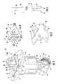
- FIG. 2is a perspective view of the locking components of the valve shown in FIG. 1 ;
- FIG. 3is a perspective view of the valve shown in FIG. 1 , shown in the locked position with the valve open;
- FIG. 4is a perspective view of the top valve plate
- FIG. 5is a perspective view of the base plate of the valve assembly
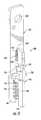
- FIG. 6is a front elevational view of the locking slide plate incorporated in the valve shown in FIGS. 1-3 ;
- FIG. 7is a perspective view of an alternative embodiment of the valve shown, partly in phantom form and in a locked valve open position;
- FIG. 8is a perspective view of the valve body and the locking mechanism associated with the valve body
- FIG. 9is a perspective view of the components of the compound locking slide plate shown in FIG. 7 ;
- FIG. 10is a perspective view of the components shown in FIG. 9 during the assembly process
- FIG. 11is a perspective view of the components of the locking slide plate shown assembled
- FIG. 12is a perspective view of the valve assembly, shown in an unlocked valve open position
- FIG. 13is a perspective view of the valve of FIG. 12 shown in an unlocked valve closed position
- FIG. 14is a perspective view of the valve shown in FIG. 7 , but shown in a locked closed valve position.
- valve installation for a hot or cold fluid systemwhich includes a valve assembly 10 which, in the embodiment shown, is a ball-type valve having a valve body 12 .
- the ball valvecan be of generally conventional construction, including a ball 54 ( FIGS. 12-14 ) with a valve seat 50 and a passageway 51 .
- the ballrotates within the body of the valve 12 between open and closed positions to allow or stop the flow of fluid through the valve.
- Extending upwardly from the valve bodyis a valve stem 14 which is keyed to an aperture 21 ( FIG. 5 ) in a valve base plate 20 and secured thereto by a lock nut 15 .
- Valve body 12includes a pair of orthogonally aligned tabs 16 and 18 which align with the locking mechanism of the present invention to selectively lock the valve in an open position, as seen in FIG. 1 , or rotated 90° to align with tab 18 to selectively lock the valve in a closed position.
- the valve assemblyincludes a handle 11 with a cylindrical extension 13 which engages the base plate to rotate the ball 54 . Extension 13 also positions the handle 11 in spaced relationship to the valve body 12 .
- the cylindrical extension 13extends between valve handle 11 and base plate 20 to which the extension is fixedly secured by interlocking tabs on member 13 and slots 22 on plate 20 and fastening screws 29 .
- a floating cylindrical sleeve 17typically surrounds the valve handle extension 13 to provide an interface between fixed insulation 25 surrounding the valve and the movable valve handle 11 and extension 13 . This allows the valve handle to move without disturbing the surrounding insulation 25 .
- An cap 27fills the cylindrical extension 13 of the valve handle and has suitable apertures allowing for freedom of movement of the locking assembly described below.
- the body of the ball valvecan include any type of interconnection with fluid conduits (not shown) including, for example, threaded socket 19 at each end of the valve, as illustrated in FIG. 1 .
- the handle 11 of the valve assembly 10can be locked in open or closed positions by the unique locking system now described in detail in connection with FIGS. 2-6 .
- the locking assembly 30includes a locking slide plate 32 which, as seen in FIG. 6 , includes a pair of spaced-apart tines 34 and 36 which extend through slots 24 and 26 , respectively, in the base plate 20 and over one of the locking tabs 16 or 18 of the valve body 12 , as seen, for example, in FIG. 3 , when the valve is in a locked open position and the locking slide plate 32 is lowered. Locking slide plate 32 is biased to an unlocked position, as seen in FIGS.
- the locking slide plate 32includes a pair of shoulders 38 with an upwardly extending leg 39 including an aperture 31 for receiving a lock when it is desired to lock the valve in an open or closed position.
- the shoulders 38captively hold locking slide plate 32 in the valve body by engaging the underside of top plate 40 adjacent slot 44 ( FIG. 4 ).
- the spring 35urges the locking slide plate 32 toward an unlocked position with leg 39 extending through a top valve plate 40 .
- Plate 40is secured to the top surface of valve handle 11 , as illustrated in FIG. 1 by means of a plurality of fasteners 41 at the corners of the outwardly extending mounting tabs 43 of valve plate 40 .
- the valve plate 40defines a locking member associated with the valve handle.
- the valve handlemay, however, integrally include the structure of valve plate 40 to achieve the locking valve assembly of this invention.
- the top valve plate 40includes a slot 44 through which the leg 39 of locking slide plate 32 extends and through an upwardly extending formed locking box 45 consisting of legs 46 and 47 , an upper wall 48 with a slot 49 aligned with slot 44 .
- the legs 46 and 47each include an aperture 42 which aligns with aperture 31 in the locking slide plate when it is pushed downwardly against bias spring 35 , as shown in FIG. 3 . In this position, the tines 34 and 36 surround the locking tab 16 (shown in the valve locked open position).
- the aperture 31 and locking slide platealign with the apertures 42 in the top valve plate 40 to allow a lock, such as a padlock 28 (shown schematically in FIG. 3 ), to be positioned through the aligned apertures for locking the valve in position.
- the locking slide plate 32normally is biased to an unlocked position, as shown in FIGS. 1 and 2 , by spring 35 , such that the tines 34 and 36 do not extend below the slots 24 and 26 of plate 20 and, therefore, allow the handle 11 to be rotated from the open position aligned with tab 16 to a 90° rotated closed position whereby the tines 34 and 36 would be aligned with tab 18 .
- the end of leg 39can be pressed downwardly against the bias spring 35 and the lock inserted through apertures 31 in the locking slide plate 32 and apertures 42 in the top plate 40 for locking the valve in a selected open or closed position.
- This embodimentworks well for a given diameter of the valve body 12 and the length of locking slide plate 32 can be selected to accommodate different valve body diameters.
- a universal compound locking slide plateis disclosed in the second embodiment, which is independent of the diameter of valve bodies and now described in connection with FIGS. 7-14 .
- the same part numbers used for the first embodiment of FIGS. 1-6are employed for the valve body, valve handle, extension, and the top plate.
- the primary differenceis the use of a compound locking mechanism 130 including two separate sliding plates 140 and 150 and two bias springs 145 , 170 as compared to the first embodiment.
- the valve assembly 110 shown in FIG. 7includes the same handle 11 as in the first embodiment, and a similar top plate 30 attached to the upper surface of valve handle 11 by fasteners 41 .
- the only difference in the top plate 30is that it is formed with U-shaped upward legs 46 and 47 , each having an aperture 42 aligned with one another for receiving the lock (such as lock 28 of FIG. 3 ) between the top valve plate 40 and the locking mechanism now described.
- the locking mechanism 130is best seen in FIG. 8 and includes a lower locking slide plate 140 and an upper locking slide plate 150 , which are interconnected to one another, as illustrated in the assembly views of FIGS. 9-11 .
- the upper slide plate 150 and lower slide plate 140are generally rectangular plates with plate 150 extending through slot 44 in top plate 40 , as seen in FIG. 7 .
- Plate 150includes an aperture 152 which aligns with apertures 42 of the top plate 40 , such that the sliding locking mechanism 130 can be locked into a locking position, as shown in FIGS. 7 and 8 .
- Slide plate 150includes a rectangular opening 154 at an end opposite the locking aperture 152 and includes orthogonally angled pairs of spaced tines 156 and 158 which guidably support slide plate 150 in its sliding movement with respect to the lower slide plate 140 .
- Adjacent opening 154is a tab 155 which aligns with and engages the upper end of spring 170 between plates 140 and 150 , as best seen in FIG. 11 .
- the lower slide plate 140includes a pair of tines 144 and 146 which span the locking tabs 16 and 18 of valve body 12 when in a lowered locked position.
- a second bias spring 145urges the lower locking slide plate 140 (and the connected upper slide plate 150 ) away from the locking position.
- Spring 145is captively held in slot 143 between tines 144 and 146 and fits over tab 147 at the upper end of slot 143 .
- the lower end of spring 145is captively held by the upwardly extending pin 23 in base plate 20 , as seen in FIG. 7 .
- Slide plate 140includes an inverted L-shaped slot 142 which receives the tines 156 and 158 on the end of slide plate 150 , as seen in FIGS.
- the spring constant of spring 170is selected to be slightly greater (i.e., a stiffer spring) than the bias spring 145 , such that depression of the upper locking slide plate 150 will force the lower slide plate 140 into a locking position surrounding one of the tabs 16 or 18 of the valve.
- the upper slide plate 150When unlocked, the upper slide plate 150 is in the position as illustrated in FIG. 12 (with the valve in an open position) or FIG. 14 (with the valve in a closed position). When, however, it is desired to lock the valve in either of those positions, pressing downwardly on a single slide member may not allow the aperture, such as aperture 31 the first embodiment, to extend downwardly sufficiently to align with the mating apertures in the top valve plate.
- the embodiment of the slide members of FIGS. 7-14is employed. With the embodiment shown in FIGS. 7-14 , however, the upper plate 150 can slide along slot 142 and compress spring 170 once tines 144 and 146 bottom out on base valve body 12 .
- FIGS. 12 and 13show the valve in an unlocked open position and an unlocked closed position, respectively.
- FIGS. 7 and 8show the locking assembly 130 and the valve in an open locked position.
- FIG. 14shows the valve in a closed locked position.
Landscapes
- Engineering & Computer Science (AREA)
- General Engineering & Computer Science (AREA)
- Mechanical Engineering (AREA)
- Preventing Unauthorised Actuation Of Valves (AREA)
- Float Valves (AREA)
Abstract
Description
The present invention relates to valves and particularly to a valve handle which can selectively lock the valve in open or closed positions with a locking slide.
Valves, and particularly ball valves, typically have stops for controlling the handle between fully open and fully closed positions while still allowing intermediate positions, if desired. In most applications, the valve is left in one of a fully open or fully closed position. In most installations, it is undesirable to inadvertently change the selected fully open or fully closed position. Prevention of inadvertent movement of the valve can be accomplished in a number of ways, including, for example, valve handle locks, such as disclosed in U.S. Pat. Nos. 5,427,135; 5,785,074; and D 358,455, in which locking rings or tabs are positioned to engage a valve handle and include apertures which permit a lock, such as a padlock, to be inserted between the locking member and the handle to prevent tampering with the valve when in a selected position. Allowed US Patent Publication No. 2015/0101684 entitled VALVE HANDLE LOCK, filed on Oct. 3, 2014, discloses yet another valve lock which provides the additional feature of allowing the valve to be held in a fixed position without locking or to prevent inadvertent motion of the valve. It also allows a padlock to be inserted to prevent tampering with the valve.
Some valves employed in connection with pipe systems carrying hot or cold fluids are insulated and, to accommodate the insulation, cylindrical extensions between the valve handle and the valve body are employed. An example of such a valve is a ball valve which has been sold for many years by NIBCO Inc. of Elkhart, Ind., under the trademark NIB-SEAL®. Due to the unique construction of such valves, they pose a significantly more difficult challenge in order to provide locking mechanisms without interfering with the insulated valve body and pipes to which the valves are connected.
The valve system of the present invention provides the ability to lock an insulated valve by providing a locking slide plate which extends in an axial direction parallel to and offset from the axis of the valve stem and selectively extends through a base plate mounted to the top of a valve to selectively engage stop tabs on the valve body. The locking slide plate also extends through the valve handle and through a locking member associated with the valve handle to selectively lock the valve in open or closed positions.
In a preferred embodiment, the locking slide plate has spaced-apart tines at its lower end which can selectively span the stop tabs on the valve body and includes a bias spring which urges the locking slide plate toward an unlocked position. In another embodiment, the locking slide plate comprises two sections which include a lower section having tines which selectively engage tabs on the valve body and a second upper section which is spring-biased to the lower section to float to allow the lower section to accommodate different diameter valve bodies and allow the upper section to lock to the locking member.
In each embodiment, a shoulder on the locking slide plate captively holds the locking slide plate between the valve body and handle. The locking slide plates of either embodiment include an aperture which aligns with an aperture in the locking member, which can be an upper valve plate attached to the valve handle, when the locking slide plate is depressed against the spring pressure to align the locking apertures, such that a lock can be inserted between the locking slide plate and the upper valve plate to lock the valve in a selected open or closed position.
Such a design, therefore, allows a valve which may be installed in an insulated environment and employs an extended handle for such purpose to be locked in open or closed positions, utilizing a minimum of parts and provides reliable operation in such an environment. These and other features, objects and advantages of the present invention will become apparent upon reading the following description thereof together with reference to the accompanying drawings.
Referring initially toFIG. 1 , there is shown a valve installation for a hot or cold fluid system which includes avalve assembly 10 which, in the embodiment shown, is a ball-type valve having avalve body 12. The ball valve can be of generally conventional construction, including a ball54 (FIGS. 12-14 ) with avalve seat 50 and apassageway 51. The ball rotates within the body of thevalve 12 between open and closed positions to allow or stop the flow of fluid through the valve. Extending upwardly from the valve body is avalve stem 14 which is keyed to an aperture21 (FIG. 5 ) in avalve base plate 20 and secured thereto by alock nut 15.Valve body 12 includes a pair of orthogonally alignedtabs FIG. 1 , or rotated 90° to align withtab 18 to selectively lock the valve in a closed position. The valve assembly includes ahandle 11 with acylindrical extension 13 which engages the base plate to rotate theball 54.Extension 13 also positions thehandle 11 in spaced relationship to thevalve body 12.
In environments where thevalve assembly 10 is employed with hot or cold fluids, such as in an HVAC system, thecylindrical extension 13 extends betweenvalve handle 11 andbase plate 20 to which the extension is fixedly secured by interlocking tabs onmember 13 andslots 22 onplate 20 and fasteningscrews 29. A floatingcylindrical sleeve 17 typically surrounds thevalve handle extension 13 to provide an interface betweenfixed insulation 25 surrounding the valve and themovable valve handle 11 andextension 13. This allows the valve handle to move without disturbing the surroundinginsulation 25. Ancap 27 fills thecylindrical extension 13 of the valve handle and has suitable apertures allowing for freedom of movement of the locking assembly described below. The body of the ball valve can include any type of interconnection with fluid conduits (not shown) including, for example, threadedsocket 19 at each end of the valve, as illustrated inFIG. 1 .
Thehandle 11 of thevalve assembly 10 can be locked in open or closed positions by the unique locking system now described in detail in connection withFIGS. 2-6 . Thelocking assembly 30 includes alocking slide plate 32 which, as seen inFIG. 6 , includes a pair of spaced-apart tines slots base plate 20 and over one of thelocking tabs valve body 12, as seen, for example, inFIG. 3 , when the valve is in a locked open position and thelocking slide plate 32 is lowered.Locking slide plate 32 is biased to an unlocked position, as seen inFIGS. 1 and 2 , by aspring 35 which extends over apost 23 extending upwardly from thebase plate 20 to position the lower end ofspring 35 with respect to the base plate. The upper end ofspring 35 surrounds and is captively held by atab 33 centered in theslot 37 betweentines locking slide plate 32 includes a pair ofshoulders 38 with an upwardly extendingleg 39 including anaperture 31 for receiving a lock when it is desired to lock the valve in an open or closed position. Theshoulders 38 captively holdlocking slide plate 32 in the valve body by engaging the underside oftop plate 40 adjacent slot44 (FIG. 4 ). Thespring 35, as seen inFIG. 2 , urges thelocking slide plate 32 toward an unlocked position withleg 39 extending through atop valve plate 40.Plate 40 is secured to the top surface ofvalve handle 11, as illustrated inFIG. 1 by means of a plurality offasteners 41 at the corners of the outwardly extendingmounting tabs 43 ofvalve plate 40. Thevalve plate 40 defines a locking member associated with the valve handle. The valve handle may, however, integrally include the structure ofvalve plate 40 to achieve the locking valve assembly of this invention.
Thetop valve plate 40, as best seen inFIG. 4 , includes aslot 44 through which theleg 39 oflocking slide plate 32 extends and through an upwardly extending formedlocking box 45 consisting oflegs upper wall 48 with aslot 49 aligned withslot 44. Thelegs aperture 42 which aligns withaperture 31 in the locking slide plate when it is pushed downwardly againstbias spring 35, as shown inFIG. 3 . In this position, thetines aperture 31 and locking slide plate align with theapertures 42 in thetop valve plate 40 to allow a lock, such as a padlock28 (shown schematically inFIG. 3 ), to be positioned through the aligned apertures for locking the valve in position.
In operation, thelocking slide plate 32 normally is biased to an unlocked position, as shown inFIGS. 1 and 2 , byspring 35, such that thetines slots plate 20 and, therefore, allow thehandle 11 to be rotated from the open position aligned withtab 16 to a 90° rotated closed position whereby thetines tab 18. In either position, the end ofleg 39 can be pressed downwardly against thebias spring 35 and the lock inserted throughapertures 31 in thelocking slide plate 32 andapertures 42 in thetop plate 40 for locking the valve in a selected open or closed position. This embodiment works well for a given diameter of thevalve body 12 and the length of lockingslide plate 32 can be selected to accommodate different valve body diameters.
A universal compound locking slide plate, however, is disclosed in the second embodiment, which is independent of the diameter of valve bodies and now described in connection withFIGS. 7-14 . In the alternative embodiment illustrated inFIGS. 7-14 , the same part numbers used for the first embodiment ofFIGS. 1-6 are employed for the valve body, valve handle, extension, and the top plate. The primary difference is the use of acompound locking mechanism 130 including two separate slidingplates
Thevalve assembly 110 shown inFIG. 7 includes thesame handle 11 as in the first embodiment, and a similartop plate 30 attached to the upper surface of valve handle11 byfasteners 41. The only difference in thetop plate 30 is that it is formed with U-shapedupward legs aperture 42 aligned with one another for receiving the lock (such aslock 28 ofFIG. 3 ) between thetop valve plate 40 and the locking mechanism now described.
Thelocking mechanism 130 is best seen inFIG. 8 and includes a lowerlocking slide plate 140 and an upperlocking slide plate 150, which are interconnected to one another, as illustrated in the assembly views ofFIGS. 9-11 . Theupper slide plate 150 andlower slide plate 140 are generally rectangular plates withplate 150 extending throughslot 44 intop plate 40, as seen inFIG. 7 .Plate 150 includes anaperture 152 which aligns withapertures 42 of thetop plate 40, such that the slidinglocking mechanism 130 can be locked into a locking position, as shown inFIGS. 7 and 8 .Slide plate 150 includes arectangular opening 154 at an end opposite the lockingaperture 152 and includes orthogonally angled pairs of spacedtines slide plate 150 in its sliding movement with respect to thelower slide plate 140.Adjacent opening 154 is atab 155 which aligns with and engages the upper end ofspring 170 betweenplates FIG. 11 .
Thelower slide plate 140 includes a pair oftines tabs valve body 12 when in a lowered locked position. Asecond bias spring 145 urges the lower locking slide plate140 (and the connected upper slide plate150) away from the locking position.Spring 145 is captively held inslot 143 betweentines tab 147 at the upper end ofslot 143. The lower end ofspring 145 is captively held by the upwardly extendingpin 23 inbase plate 20, as seen inFIG. 7 .Slide plate 140 includes an inverted L-shapedslot 142 which receives thetines slide plate 150, as seen inFIGS. 10 and 11 , with thetines plate 140 along thevertical section 141 ofslot 142.Spring 170 is captively held to the upper end ofplate 140 by atab 148 at the lower end ofslot 142 andspring 170 and by inwardly projectingshoulders 149 at the top ofslot 142 andspring 170. When slidingplates FIGS. 7, 8, and 11 ,tab 155 of the sliding plate extends into and engages the upper end ofspring 170. When connected,plates slide mechanism 130. The spring constant ofspring 170 is selected to be slightly greater (i.e., a stiffer spring) than thebias spring 145, such that depression of the upperlocking slide plate 150 will force thelower slide plate 140 into a locking position surrounding one of thetabs
Normally, when unlocked, theupper slide plate 150 is in the position as illustrated inFIG. 12 (with the valve in an open position) orFIG. 14 (with the valve in a closed position). When, however, it is desired to lock the valve in either of those positions, pressing downwardly on a single slide member may not allow the aperture, such asaperture 31 the first embodiment, to extend downwardly sufficiently to align with the mating apertures in the top valve plate. In order to compensate for variations in the distance betweenbase plate 20 and thevalve body 12, the embodiment of the slide members ofFIGS. 7-14 is employed. With the embodiment shown inFIGS. 7-14 , however, theupper plate 150 can slide alongslot 142 andcompress spring 170 oncetines base valve body 12. This allows theupper plate 150 to move downwardly an additional distance defined by the length of the vertically extendingleg 141 ofslot 142 to align lock-receivingapertures compressible locking slide 150.FIGS. 12 and13 show the valve in an unlocked open position and an unlocked closed position, respectively.FIGS. 7 and 8 , on the other hand, show the lockingassembly 130 and the valve in an open locked position.FIG. 14 shows the valve in a closed locked position.
It will become apparent to those skilled in the art that various modifications to the preferred embodiment of the invention as described herein can be made without departing from the spirit or scope of the invention as defined by the appended claims.
Claims (20)
1. A valve locking system comprising:
a valve body having a valve stem coupled to a fluid control element movable by a valve handle coupled to said valve stem, said valve body including at least one tab for defining a predetermined position of said fluid control element and wherein said handle includes a locking member;
a base plate mounted to said valve body and to said valve stem to selectively engage said tab on the valve body to position said fluid control element at said predetermined position; and
a locking slide plate which extends through said base plate in an axial direction parallel to and offset from the axis of said valve stem to selectively engage said tab on said valve body, said locking slide plate also extending through the valve handle and through said locking member to selectively lock said valve in said predetermined position.
2. The valve locking system as defined inclaim 1 wherein said locking slide plate has spaced-apart tines at one end which can selectively span said tab on the valve body for holding said valve in said predetermined position.
3. The valve locking system as defined inclaim 2 and further including a bias spring which urges said tines of said locking slide plate away from said tab toward an unlocked position.
4. The valve locking system as defined inclaim 1 wherein said locking slide plate comprises two sections including a lower section having spaced-apart tines which selectively engage said tab on said valve body and an upper section which is spring-biased to the lower section to float to allow the lower section to accommodate different diameter valve bodies and allow the upper section to move to a locking position with respect to said locking member.
5. The valve locking system as defined inclaim 1 wherein an end of said locking slide plate remote from said valve body includes an aperture which aligns with an aperture in said locking member of said valve handle when the locking slide plate is moved to engage said tab, such that a lock can be inserted between said locking slide plate and said locking member to lock the valve in a selected position.
6. The valve locking system as defined inclaim 5 wherein said locking member includes an upper valve plate attached to said handle, said plate having a slot through which said locking slide plate extends and a side wall including said aperture.
7. A valve locking system comprising:
a valve body having a valve stem coupled to a fluid control element movable by a valve handle coupled to said valve stem, said valve body including a pair of spaced-apart tabs defining open and closed positions of said fluid control element and wherein said valve handle includes a locking member;
a base plate mounted to said valve body and to said valve stem to selectively engage said tabs on the valve body to position said fluid control element at said open and closed positions;
a valve handle extension extending from said handle to said base plate for moving said fluid control element with movement of said valve handle; and
a locking slide plate which extends through said base plate in an axial direction parallel to and offset from the axis of said valve stem to selectively engage said tabs on said valve body, said locking slide plate also extending through the valve handle and through said locking member to selectively lock said valve in open and closed positions.
8. The valve locking system as defined inclaim 7 wherein said locking slide plate has spaced-apart tines at one end which can selectively span said tabs on the valve body for holding said valve in a selected one of said predetermined positions.
9. The valve locking system as defined inclaim 8 and further including a bias spring which urges said tines of said locking slide plate away from said tabs toward an unlocked position.
10. The valve locking system as defined inclaim 7 wherein said locking slide plate comprises two sections including a lower section having spaced-apart tines which selectively engage said tabs on said valve body and an upper section which is movably coupled to said lower section and spring-biased to the lower section to float to allow the upper section to move to a locking position with respect to said locking member.
11. The valve locking system as defined inclaim 10 wherein an end of said locking slide plate remote from said valve body includes an aperture which aligns with an aperture in said locking member of said valve handle when the locking slide plate is moved to engage one of said tabs, such that a lock can be inserted between said locking slide plate and said locking member to lock the valve in a selected position.
12. The valve locking system as defined inclaim 7 wherein an end of said locking slide plate remote from said valve body includes an aperture which aligns with an aperture in said locking member of said valve handle when the locking slide plate is moved to engage one of said tabs, such that a lock can be inserted between said locking slide plate and said locking member to lock the valve in a selected position.
13. The valve locking system as defined inclaim 12 wherein said locking member includes an upper valve plate attached to said handle, said plate having a slot through which said locking slide plate extends and a side including an aperture for receiving a lock.
14. A valve locking system comprising:
a ball valve having a valve stem and a handle and a top valve plate coupled to said handle;
a valve handle extension coupled to said handle and extending toward said body of said valve, said valve body including a pair of spaced-apart tabs defining open and closed positions of said valve;
a base plate mounted to said valve body and to a valve stem of said body, said base plate coupled to said extension to selectively engage said tabs on said valve body to position said ball valve at said open and closed positions; and
a locking slide plate which extends through said top valve plate and said base plate in an axial direction parallel to and offset from the axis of said valve stem to selectively engage said tabs on said valve body to selectively lock said ball valve in open or closed positions.
15. The valve locking system as defined inclaim 14 wherein said locking slide plate has spaced-apart tines at one end which can selectively span said tabs on the valve body for holding said valve in a selected open or closed position.
16. The valve locking system as defined inclaim 15 and further including a bias spring which urges said tines of said locking slide plate away from said tabs toward an unlocked position.
17. The valve locking system as defined inclaim 14 wherein said locking slide plate comprises two sections including a lower section having spaced-apart tines which selectively engage said tabs on said valve body and an upper section which is movably coupled to said lower section and spring-biased to the lower section to float to allow the lower section to accommodate different diameter valve bodies and allow the upper section to move to a locking position with respect to said top valve plate.
18. The valve locking system as defined inclaim 17 wherein an end of said locking slide plate remote from said valve body includes an aperture which aligns with an aperture in said top valve plate when the locking slide plate is moved to engage one of said tabs, such that a lock can be inserted between said locking slide plate and said top valve plate to lock the valve in a selected position.
19. The valve locking system as defined inclaim 14 wherein an end of said locking slide plate remote from said valve body includes an aperture which aligns with an aperture in said top valve plate when the locking slide plate is moved to engage one of said tabs, such that a lock can be inserted between said locking slide plate and said top valve plate to lock the valve in a selected position.
20. The valve locking system as defined inclaim 14 wherein said extension is a cylindrical sleeve.
Priority Applications (3)
| Application Number | Priority Date | Filing Date | Title |
|---|---|---|---|
| US15/046,615US9810344B2 (en) | 2016-02-18 | 2016-02-18 | Valve with locking slide |
| CA2957623ACA2957623C (en) | 2016-02-18 | 2017-02-08 | Valve with locking slide |
| MX2017002254AMX365800B (en) | 2016-02-18 | 2017-02-20 | Valve with locking slide. |
Applications Claiming Priority (1)
| Application Number | Priority Date | Filing Date | Title |
|---|---|---|---|
| US15/046,615US9810344B2 (en) | 2016-02-18 | 2016-02-18 | Valve with locking slide |
Publications (2)
| Publication Number | Publication Date |
|---|---|
| US20170241565A1 US20170241565A1 (en) | 2017-08-24 |
| US9810344B2true US9810344B2 (en) | 2017-11-07 |
Family
ID=59593739
Family Applications (1)
| Application Number | Title | Priority Date | Filing Date |
|---|---|---|---|
| US15/046,615Active2036-04-15US9810344B2 (en) | 2016-02-18 | 2016-02-18 | Valve with locking slide |
Country Status (3)
| Country | Link |
|---|---|
| US (1) | US9810344B2 (en) |
| CA (1) | CA2957623C (en) |
| MX (1) | MX365800B (en) |
Families Citing this family (3)
| Publication number | Priority date | Publication date | Assignee | Title |
|---|---|---|---|---|
| DE102016200206B4 (en)* | 2016-01-11 | 2020-08-13 | Protechna S.A. | REMOVAL FITTING FOR LIQUID CONTAINERS |
| CN107990040B (en)* | 2017-11-30 | 2020-01-17 | 长园共创电力安全技术股份有限公司 | Rising stem valve lock and intelligent lock control system |
| CN108443573B (en)* | 2018-03-22 | 2020-01-17 | 长园共创电力安全技术股份有限公司 | Valve lock and valve management and control system |
Citations (28)
| Publication number | Priority date | Publication date | Assignee | Title |
|---|---|---|---|---|
| US195611A (en) | 1877-09-25 | Improvement in lock-cocks | ||
| US1139208A (en) | 1914-08-20 | 1915-05-11 | John T Gorman | Gas-cock. |
| US1437369A (en) | 1921-02-02 | 1922-11-28 | Herbert Harsh | Gas cock |
| US3648970A (en) | 1970-02-27 | 1972-03-14 | Stile Craft Mfg Inc | Handle assmebly for a rotatable ball valve |
| US3679170A (en) | 1971-03-08 | 1972-07-25 | Dow Chemical Co | Ball valve with positive locking mechanism |
| US4126023A (en)* | 1977-04-14 | 1978-11-21 | Watts Regulator Co. | Tamperproof locking and latching mechanism for rotatable controls |
| US4208033A (en) | 1978-07-24 | 1980-06-17 | Dover Corporation | Locking device for a ball valve |
| US4756507A (en) | 1987-07-06 | 1988-07-12 | Mcandrew William J | Ball or plug valve stem extension and lock mechanism |
| USD297354S (en) | 1985-11-27 | 1988-08-23 | Precision Fitting and Valve Company, Inc. | Locking fluid valve |
| US5014528A (en)* | 1990-08-27 | 1991-05-14 | Milwaukee Valve Company, Inc. | Tamper-proof locking mechanism for quarter turn valves |
| US5115834A (en)* | 1991-10-08 | 1992-05-26 | Neles-Jamesbury, Inc. | Valve-locking device |
| US5139041A (en) | 1992-01-27 | 1992-08-18 | Albrecht David E | Stop and lock plate for use with valve |
| US5165263A (en) | 1992-01-17 | 1992-11-24 | Claude Perron | Valve lock |
| US5213308A (en) | 1992-06-12 | 1993-05-25 | Whitey Company | Valve with handle latch/lock |
| US5236006A (en) | 1992-04-22 | 1993-08-17 | Platusich Bruce M | Insulated HVAC valve assembly |
| USD358455S (en) | 1992-08-24 | 1995-05-16 | Nibco, Inc. | Valve lock |
| US5427135A (en) | 1992-08-24 | 1995-06-27 | Nibco, Inc. | Valve lock |
| US5579804A (en)* | 1995-10-10 | 1996-12-03 | Milwaukee Valve Company, Inc. | Tamper-proof handle extension for quarter turn valves |
| US5709112A (en)* | 1995-12-28 | 1998-01-20 | Kennedy; Steven | Tamperproof locking and latching mechanism for rotatable controls |
| US5785074A (en) | 1997-01-02 | 1998-07-28 | Nibco, Inc. | Vented ball valve with lock-out ring |
| US7044148B2 (en) | 2003-02-28 | 2006-05-16 | Sabber Design & Manufacturing | Apparatus and method for selectively securing a valve in an open or closed position |
| CN101709791A (en) | 2009-12-14 | 2010-05-19 | 浙江海亮股份有限公司 | Ball valve with lock |
| CN201487368U (en) | 2009-05-26 | 2010-05-26 | 浙江通用阀门有限公司 | Lock type valve |
| CN201763994U (en) | 2010-01-13 | 2011-03-16 | 浙江沃尔达铜业有限公司 | Ball valve with locking device |
| US8205859B2 (en) | 2009-05-21 | 2012-06-26 | Conbraco Industries, Inc. | Extended valve handle |
| CN203223586U (en) | 2013-04-23 | 2013-10-02 | 宁波日安阀门有限公司 | Flanged ball valve with open-close locking device |
| US8740180B2 (en) | 2006-03-20 | 2014-06-03 | Asahi Organic Chemicals Industry Co., Ltd. | Rotary valve |
| US9297477B2 (en) | 2013-10-16 | 2016-03-29 | Nibco Inc. | Valve handle lock |
- 2016
- 2016-02-18USUS15/046,615patent/US9810344B2/enactiveActive
- 2017
- 2017-02-08CACA2957623Apatent/CA2957623C/enactiveActive
- 2017-02-20MXMX2017002254Apatent/MX365800B/enactiveIP Right Grant
Patent Citations (28)
| Publication number | Priority date | Publication date | Assignee | Title |
|---|---|---|---|---|
| US195611A (en) | 1877-09-25 | Improvement in lock-cocks | ||
| US1139208A (en) | 1914-08-20 | 1915-05-11 | John T Gorman | Gas-cock. |
| US1437369A (en) | 1921-02-02 | 1922-11-28 | Herbert Harsh | Gas cock |
| US3648970A (en) | 1970-02-27 | 1972-03-14 | Stile Craft Mfg Inc | Handle assmebly for a rotatable ball valve |
| US3679170A (en) | 1971-03-08 | 1972-07-25 | Dow Chemical Co | Ball valve with positive locking mechanism |
| US4126023A (en)* | 1977-04-14 | 1978-11-21 | Watts Regulator Co. | Tamperproof locking and latching mechanism for rotatable controls |
| US4208033A (en) | 1978-07-24 | 1980-06-17 | Dover Corporation | Locking device for a ball valve |
| USD297354S (en) | 1985-11-27 | 1988-08-23 | Precision Fitting and Valve Company, Inc. | Locking fluid valve |
| US4756507A (en) | 1987-07-06 | 1988-07-12 | Mcandrew William J | Ball or plug valve stem extension and lock mechanism |
| US5014528A (en)* | 1990-08-27 | 1991-05-14 | Milwaukee Valve Company, Inc. | Tamper-proof locking mechanism for quarter turn valves |
| US5115834A (en)* | 1991-10-08 | 1992-05-26 | Neles-Jamesbury, Inc. | Valve-locking device |
| US5165263A (en) | 1992-01-17 | 1992-11-24 | Claude Perron | Valve lock |
| US5139041A (en) | 1992-01-27 | 1992-08-18 | Albrecht David E | Stop and lock plate for use with valve |
| US5236006A (en) | 1992-04-22 | 1993-08-17 | Platusich Bruce M | Insulated HVAC valve assembly |
| US5213308A (en) | 1992-06-12 | 1993-05-25 | Whitey Company | Valve with handle latch/lock |
| USD358455S (en) | 1992-08-24 | 1995-05-16 | Nibco, Inc. | Valve lock |
| US5427135A (en) | 1992-08-24 | 1995-06-27 | Nibco, Inc. | Valve lock |
| US5579804A (en)* | 1995-10-10 | 1996-12-03 | Milwaukee Valve Company, Inc. | Tamper-proof handle extension for quarter turn valves |
| US5709112A (en)* | 1995-12-28 | 1998-01-20 | Kennedy; Steven | Tamperproof locking and latching mechanism for rotatable controls |
| US5785074A (en) | 1997-01-02 | 1998-07-28 | Nibco, Inc. | Vented ball valve with lock-out ring |
| US7044148B2 (en) | 2003-02-28 | 2006-05-16 | Sabber Design & Manufacturing | Apparatus and method for selectively securing a valve in an open or closed position |
| US8740180B2 (en) | 2006-03-20 | 2014-06-03 | Asahi Organic Chemicals Industry Co., Ltd. | Rotary valve |
| US8205859B2 (en) | 2009-05-21 | 2012-06-26 | Conbraco Industries, Inc. | Extended valve handle |
| CN201487368U (en) | 2009-05-26 | 2010-05-26 | 浙江通用阀门有限公司 | Lock type valve |
| CN101709791A (en) | 2009-12-14 | 2010-05-19 | 浙江海亮股份有限公司 | Ball valve with lock |
| CN201763994U (en) | 2010-01-13 | 2011-03-16 | 浙江沃尔达铜业有限公司 | Ball valve with locking device |
| CN203223586U (en) | 2013-04-23 | 2013-10-02 | 宁波日安阀门有限公司 | Flanged ball valve with open-close locking device |
| US9297477B2 (en) | 2013-10-16 | 2016-03-29 | Nibco Inc. | Valve handle lock |
Also Published As
| Publication number | Publication date |
|---|---|
| MX365800B (en) | 2019-06-14 |
| CA2957623A1 (en) | 2017-08-18 |
| US20170241565A1 (en) | 2017-08-24 |
| CA2957623C (en) | 2020-02-18 |
| MX2017002254A (en) | 2018-08-15 |
Similar Documents
| Publication | Publication Date | Title |
|---|---|---|
| CA2957623C (en) | Valve with locking slide | |
| US9297477B2 (en) | Valve handle lock | |
| US7758016B2 (en) | Ball valve | |
| US4218785A (en) | Drain assembly for a lavatory basin | |
| JP3417562B2 (en) | Valve with handle latch / lock | |
| US7814924B2 (en) | Seismic safety valve and valve actuator | |
| KR102375630B1 (en) | Lockout tagout device and valve | |
| CN105089119B (en) | Drain plug interlock apparatus | |
| EP3462067B1 (en) | Differential pressure valve | |
| US9206917B2 (en) | Positioning structure of water guiding duct in faucet valve base | |
| US2710023A (en) | Check-unit or valve | |
| US20190101941A1 (en) | Regulator with convertible trim assembly | |
| EP3201502B1 (en) | Slam shut safety device | |
| US20150292626A1 (en) | Emergency shut-off valve | |
| KR101772204B1 (en) | Ball valve for preventing wheel rotation | |
| KR101156605B1 (en) | A gate valve with an optimized lfit distance of a valve stem | |
| CN103711964A (en) | Self aligning valve plug | |
| US7980530B2 (en) | Packing nut for control valve | |
| US6484743B2 (en) | Flow control assembly | |
| US5620022A (en) | Seismic gas shut-off valve with safety lock | |
| US6997434B2 (en) | Twist cam valve | |
| US20170314720A1 (en) | Apparatus and Methods for Coupling a Valve to a Duct | |
| KR102075113B1 (en) | Variable angle valve | |
| AU2002256099A1 (en) | Flow control assembly | |
| KR102868493B1 (en) | Valve equipped with lock out lever |
Legal Events
| Date | Code | Title | Description |
|---|---|---|---|
| AS | Assignment | Owner name:NIBCO INC., INDIANA Free format text:ASSIGNMENT OF ASSIGNORS INTEREST;ASSIGNORS:FRISCHE-MOURI, PAUL;BOBO, DAVID A.;KRAZIT, MATTHEW;AND OTHERS;REEL/FRAME:037763/0114 Effective date:20160217 | |
| AS | Assignment | Owner name:NIBCO INC., INDIANA Free format text:ASSIGNMENT OF ASSIGNORS INTEREST;ASSIGNOR:ANDREJKO, JOHN P.;REEL/FRAME:041657/0878 Effective date:20170320 | |
| STCF | Information on status: patent grant | Free format text:PATENTED CASE | |
| MAFP | Maintenance fee payment | Free format text:PAYMENT OF MAINTENANCE FEE, 4TH YEAR, LARGE ENTITY (ORIGINAL EVENT CODE: M1551); ENTITY STATUS OF PATENT OWNER: LARGE ENTITY Year of fee payment:4 | |
| MAFP | Maintenance fee payment | Free format text:PAYMENT OF MAINTENANCE FEE, 8TH YEAR, LARGE ENTITY (ORIGINAL EVENT CODE: M1552); ENTITY STATUS OF PATENT OWNER: LARGE ENTITY Year of fee payment:8 |