US9809993B2 - Rail skirt system - Google Patents
Rail skirt systemDownload PDFInfo
- Publication number
- US9809993B2 US9809993B2US15/177,239US201615177239AUS9809993B2US 9809993 B2US9809993 B2US 9809993B2US 201615177239 AUS201615177239 AUS 201615177239AUS 9809993 B2US9809993 B2US 9809993B2
- Authority
- US
- United States
- Prior art keywords
- shelter
- locking
- rail
- leg
- opposing
- Prior art date
- Legal status (The legal status is an assumption and is not a legal conclusion. Google has not performed a legal analysis and makes no representation as to the accuracy of the status listed.)
- Active
Links
Images


Classifications
- E—FIXED CONSTRUCTIONS
- E04—BUILDING
- E04H—BUILDINGS OR LIKE STRUCTURES FOR PARTICULAR PURPOSES; SWIMMING OR SPLASH BATHS OR POOLS; MASTS; FENCING; TENTS OR CANOPIES, IN GENERAL
- E04H15/00—Tents or canopies, in general
- E04H15/32—Parts, components, construction details, accessories, interior equipment, specially adapted for tents, e.g. guy-line equipment, skirts, thresholds
- E04H15/34—Supporting means, e.g. frames
- E04H15/44—Supporting means, e.g. frames collapsible, e.g. breakdown type
- E04H15/48—Supporting means, e.g. frames collapsible, e.g. breakdown type foldable, i.e. having pivoted or hinged means
- E—FIXED CONSTRUCTIONS
- E04—BUILDING
- E04H—BUILDINGS OR LIKE STRUCTURES FOR PARTICULAR PURPOSES; SWIMMING OR SPLASH BATHS OR POOLS; MASTS; FENCING; TENTS OR CANOPIES, IN GENERAL
- E04H15/00—Tents or canopies, in general
- E04H15/32—Parts, components, construction details, accessories, interior equipment, specially adapted for tents, e.g. guy-line equipment, skirts, thresholds
- E04H15/34—Supporting means, e.g. frames
- E04H15/44—Supporting means, e.g. frames collapsible, e.g. breakdown type
- E04H15/48—Supporting means, e.g. frames collapsible, e.g. breakdown type foldable, i.e. having pivoted or hinged means
- E04H15/50—Supporting means, e.g. frames collapsible, e.g. breakdown type foldable, i.e. having pivoted or hinged means lazy-tongs type
- E—FIXED CONSTRUCTIONS
- E04—BUILDING
- E04H—BUILDINGS OR LIKE STRUCTURES FOR PARTICULAR PURPOSES; SWIMMING OR SPLASH BATHS OR POOLS; MASTS; FENCING; TENTS OR CANOPIES, IN GENERAL
- E04H15/00—Tents or canopies, in general
- E04H15/32—Parts, components, construction details, accessories, interior equipment, specially adapted for tents, e.g. guy-line equipment, skirts, thresholds
- E04H15/54—Covers of tents or canopies
- Y—GENERAL TAGGING OF NEW TECHNOLOGICAL DEVELOPMENTS; GENERAL TAGGING OF CROSS-SECTIONAL TECHNOLOGIES SPANNING OVER SEVERAL SECTIONS OF THE IPC; TECHNICAL SUBJECTS COVERED BY FORMER USPC CROSS-REFERENCE ART COLLECTIONS [XRACs] AND DIGESTS
- Y10—TECHNICAL SUBJECTS COVERED BY FORMER USPC
- Y10T—TECHNICAL SUBJECTS COVERED BY FORMER US CLASSIFICATION
- Y10T403/00—Joints and connections
- Y10T403/34—Branched
- Y10T403/341—Three or more radiating members
- Y—GENERAL TAGGING OF NEW TECHNOLOGICAL DEVELOPMENTS; GENERAL TAGGING OF CROSS-SECTIONAL TECHNOLOGIES SPANNING OVER SEVERAL SECTIONS OF THE IPC; TECHNICAL SUBJECTS COVERED BY FORMER USPC CROSS-REFERENCE ART COLLECTIONS [XRACs] AND DIGESTS
- Y10—TECHNICAL SUBJECTS COVERED BY FORMER USPC
- Y10T—TECHNICAL SUBJECTS COVERED BY FORMER US CLASSIFICATION
- Y10T403/00—Joints and connections
- Y10T403/44—Three or more members connected at single locus
Definitions
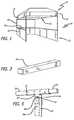
- FIG. 2is another perspective view of a collapsible shelter with a rail skirt system illustrating rail bar members and corner connecting brackets of the rail skirt system of FIG. 1 .
- FIG. 3is a schematic view of a locking end portion of the rail member of the rail skirt system of FIG. 1 .
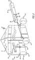
- Inner struts 62 a , 62 bextend perpendicularly from the journal arms, and forked brackets 64 a , 64 b extend from the inner struts 62 a , 62 b , respectively, and include first and second connecting arms 66 a , 66 b with opposing apertures 68 a , 68 b for receiving the outer detent pins of the second ends of the rail bar members.
- One of the inner struts 62 aincludes a tongue member 70 projecting from the inner strut 62 a
- the other inner strut 62 bincludes a corresponding groove or slot 72 that receives the tongue member.
Landscapes
- Engineering & Computer Science (AREA)
- Architecture (AREA)
- Civil Engineering (AREA)
- Structural Engineering (AREA)
- Ladders (AREA)
- Emergency Lowering Means (AREA)
- Buildings Adapted To Withstand Abnormal External Influences (AREA)
- Tents Or Canopies (AREA)
- Curtains And Furnishings For Windows Or Doors (AREA)
- Mutual Connection Of Rods And Tubes (AREA)
- Pivots And Pivotal Connections (AREA)
- Tables And Desks Characterized By Structural Shape (AREA)
- Fittings On The Vehicle Exterior For Carrying Loads, And Devices For Holding Or Mounting Articles (AREA)
- Furniture Connections (AREA)
Abstract
Description
Claims (11)
Priority Applications (1)
| Application Number | Priority Date | Filing Date | Title |
|---|---|---|---|
| US15/177,239US9809993B2 (en) | 2006-04-28 | 2016-06-08 | Rail skirt system |
Applications Claiming Priority (8)
| Application Number | Priority Date | Filing Date | Title |
|---|---|---|---|
| US79634106P | 2006-04-28 | 2006-04-28 | |
| US11/739,621US7686026B2 (en) | 2006-04-28 | 2007-04-24 | Rail skirt system |
| US12/726,515US7958903B2 (en) | 2006-04-28 | 2010-03-18 | Rail skirt system |
| US13/153,633US8166991B2 (en) | 2006-04-28 | 2011-06-06 | Rail skirt system |
| US13/455,945US8356615B2 (en) | 2006-04-28 | 2012-04-25 | Rail skirt system |
| US13/743,312US8640722B2 (en) | 2006-04-28 | 2013-01-16 | Rail skirt system |
| US14/150,048US9382724B2 (en) | 2006-04-28 | 2014-01-08 | Rail skirt system |
| US15/177,239US9809993B2 (en) | 2006-04-28 | 2016-06-08 | Rail skirt system |
Related Parent Applications (1)
| Application Number | Title | Priority Date | Filing Date |
|---|---|---|---|
| US14/150,048ContinuationUS9382724B2 (en) | 2006-04-28 | 2014-01-08 | Rail skirt system |
Publications (2)
| Publication Number | Publication Date |
|---|---|
| US20160281386A1 US20160281386A1 (en) | 2016-09-29 |
| US9809993B2true US9809993B2 (en) | 2017-11-07 |
Family
ID=38647182
Family Applications (7)
| Application Number | Title | Priority Date | Filing Date |
|---|---|---|---|
| US11/739,621Active2028-02-14US7686026B2 (en) | 2006-04-28 | 2007-04-24 | Rail skirt system |
| US12/726,515ActiveUS7958903B2 (en) | 2006-04-28 | 2010-03-18 | Rail skirt system |
| US13/153,633ActiveUS8166991B2 (en) | 2006-04-28 | 2011-06-06 | Rail skirt system |
| US13/455,945ActiveUS8356615B2 (en) | 2006-04-28 | 2012-04-25 | Rail skirt system |
| US13/743,312ActiveUS8640722B2 (en) | 2006-04-28 | 2013-01-16 | Rail skirt system |
| US14/150,048Active2027-09-22US9382724B2 (en) | 2006-04-28 | 2014-01-08 | Rail skirt system |
| US15/177,239ActiveUS9809993B2 (en) | 2006-04-28 | 2016-06-08 | Rail skirt system |
Family Applications Before (6)
| Application Number | Title | Priority Date | Filing Date |
|---|---|---|---|
| US11/739,621Active2028-02-14US7686026B2 (en) | 2006-04-28 | 2007-04-24 | Rail skirt system |
| US12/726,515ActiveUS7958903B2 (en) | 2006-04-28 | 2010-03-18 | Rail skirt system |
| US13/153,633ActiveUS8166991B2 (en) | 2006-04-28 | 2011-06-06 | Rail skirt system |
| US13/455,945ActiveUS8356615B2 (en) | 2006-04-28 | 2012-04-25 | Rail skirt system |
| US13/743,312ActiveUS8640722B2 (en) | 2006-04-28 | 2013-01-16 | Rail skirt system |
| US14/150,048Active2027-09-22US9382724B2 (en) | 2006-04-28 | 2014-01-08 | Rail skirt system |
Country Status (9)
| Country | Link |
|---|---|
| US (7) | US7686026B2 (en) |
| EP (1) | EP2013430B1 (en) |
| JP (1) | JP5079787B2 (en) |
| CN (1) | CN101438017B (en) |
| AU (1) | AU2007244794B2 (en) |
| CA (2) | CA2649568C (en) |
| ES (1) | ES2602101T3 (en) |
| MX (1) | MX2008013280A (en) |
| WO (1) | WO2007127860A2 (en) |
Cited By (1)
| Publication number | Priority date | Publication date | Assignee | Title |
|---|---|---|---|---|
| US10487530B1 (en)* | 2018-05-01 | 2019-11-26 | Byungtae JUN | Folding hexagonal tent |
Families Citing this family (10)
| Publication number | Priority date | Publication date | Assignee | Title |
|---|---|---|---|---|
| US7686026B2 (en) | 2006-04-28 | 2010-03-30 | Carter Mark C | Rail skirt system |
| US9234366B2 (en) | 2012-10-25 | 2016-01-12 | Go Papa, Lllp | Mechanisms for shelter attachments |
| US9341327B2 (en) | 2013-01-21 | 2016-05-17 | Terex Usa, Llc | Integrated carriage lighting system for concrete pavers |
| US9869110B2 (en) | 2015-09-28 | 2018-01-16 | Go Papa, Lllp | Shelter system |
| US10294691B1 (en)* | 2018-03-01 | 2019-05-21 | Nicholas Joseph Goncher | Portable shelter with rooftop opening |
| WO2019227174A1 (en)* | 2018-06-01 | 2019-12-05 | Csr Building Products Limited | Connection system |
| CN109488105A (en)* | 2018-11-24 | 2019-03-19 | 上海红快展示科技有限公司 | A kind of pocket Tent frame component |
| GB2623171B (en)* | 2021-10-08 | 2024-11-27 | Big Foot Systems Ltd | A bracing system and a support assembly and kits and parts thereof |
| GB2611566B (en)* | 2021-10-08 | 2024-01-10 | Big Foot Systems Ltd | A step elemennt and a support assembly and kits and parts thereof |
| US20240049679A1 (en)* | 2022-08-12 | 2024-02-15 | EZwhelp, Inc. | Rail connectors and spacers for animal whelping containers |
Citations (18)
| Publication number | Priority date | Publication date | Assignee | Title |
|---|---|---|---|---|
| US1846011A (en)* | 1929-10-05 | 1932-02-23 | Judson J Adams | Tent |
| US2151908A (en)* | 1938-04-21 | 1939-03-28 | Max E Gottlieb | Chapel tent |
| US2182283A (en)* | 1939-09-12 | 1939-12-05 | Thomas I Curtis | Chapel tent |
| US2840400A (en)* | 1952-11-28 | 1958-06-24 | Azzo Errol P D | Clamping structure for tubular bars |
| US3133549A (en)* | 1961-04-10 | 1964-05-19 | Delmar F Severing | Folding car cover |
| US4066089A (en)* | 1976-05-17 | 1978-01-03 | Rainwater Orman M | Collapsible shelter structure |
| US4558713A (en)* | 1982-10-29 | 1985-12-17 | American Canvas Company | Frame system and connectors for portable shelters |
| US5115828A (en)* | 1991-03-18 | 1992-05-26 | Shaffer Tent & Awning Co. | Demountable frame structure |
| US5598668A (en)* | 1995-10-04 | 1997-02-04 | Isom; Fred S. | Adjustable building frame |
| GB2362395A (en)* | 2000-05-18 | 2001-11-21 | Tsai Ming Liang | Tent with side shield |
| US6478039B2 (en)* | 2001-03-20 | 2002-11-12 | Caravan Canopy International, Inc. | Side rail assembly for canopy |
| US6502890B1 (en)* | 1998-09-01 | 2003-01-07 | Edscha Lkw-Schiebeverdecke Gmbh | Side-rail coupling for tarpaulin covers of vehicle superstructures |
| US6575656B2 (en)* | 2001-05-24 | 2003-06-10 | Caravan Canopy International, Inc. | Pull pin assembly for canopy |
| US6951327B1 (en)* | 2003-04-01 | 2005-10-04 | Northpole Limited | Detent-releasing device |
| US20060062632A1 (en)* | 2004-09-17 | 2006-03-23 | Norstar Trade, Inc. | Release pin assembly for tents and canopies |
| US7240685B2 (en)* | 2003-01-17 | 2007-07-10 | Caravan Canopy International, Inc. | Side rail assembly for a canopy including a side rail having a hook for engaging a side rail connector on an upright of the canopy |
| US7299812B2 (en)* | 2004-11-19 | 2007-11-27 | Carter Mark C | Erectable shelter with three way awning |
| US7775229B2 (en)* | 2008-08-29 | 2010-08-17 | Bravo Sports | Canopy with one or more side awnings |
Family Cites Families (40)
| Publication number | Priority date | Publication date | Assignee | Title |
|---|---|---|---|---|
| US1326006A (en) | 1919-12-23 | sterhardt | ||
| US684130A (en) | 1900-12-31 | 1901-10-08 | Albert Taubert | Screen. |
| US1493915A (en) | 1920-08-25 | 1924-05-13 | Zaring A Baker | Sun and wind shield |
| GB198803A (en) | 1922-03-14 | 1923-06-14 | Edward Robert Appleton | Improvements in or relating to collapsible frames for tents, tables and other articles of furniture |
| US1728356A (en) | 1925-09-05 | 1929-09-17 | Earl D Morgan | Tent |
| US1712836A (en) | 1927-11-19 | 1929-05-14 | Mills August | Combination bed and tent |
| US1853367A (en) | 1931-04-22 | 1932-04-12 | Ralph M Reeves | Collapsible tent frame |
| GB672815A (en) | 1949-11-25 | 1952-05-28 | Ulric Lock Orchard Lisle | Improvements in or relating to shop front blinds, awnings, tent tops or the like |
| US2898923A (en) | 1955-10-24 | 1959-08-11 | Smiley Jan Carol | Babysitter protective tents |
| US2989329A (en) | 1958-08-28 | 1961-06-20 | Ross A Noah | Extensible legged film file case and projector table |
| US3182672A (en)* | 1962-09-04 | 1965-05-11 | Hawthorn Company | Tent |
| US3174397A (en) | 1962-09-10 | 1965-03-23 | Rayan Aeronautical Co | Deployment mechanism for satellite mirror structure |
| US3199518A (en) | 1963-12-09 | 1965-08-10 | Herman A Glidewell | Collapsible shelter frame |
| US3335815A (en) | 1965-07-26 | 1967-08-15 | Thomas B Oakes Construction Co | Lazy tong devices |
| US3375624A (en) | 1965-10-11 | 1968-04-02 | Kenneth Millhiser | Structural member |
| US3496687A (en) | 1967-03-22 | 1970-02-24 | North American Rockwell | Extensible structure |
| US3526066A (en) | 1968-11-06 | 1970-09-01 | American Air Filter Co | Portable shelter |
| US4156433A (en) | 1977-06-16 | 1979-05-29 | Rupp Industries Inc. | Portable shelter |
| US4247216A (en) | 1979-08-22 | 1981-01-27 | Pansini Andrew L | Quick connect handle for swimming pool cleaning tools |
| US4607656A (en) | 1983-09-26 | 1986-08-26 | Carter Mark C | Quick erection collapsible shelter |
| US4641676A (en) | 1984-01-23 | 1987-02-10 | Lynch James P | Collapsible canopy structure |
| US4601301A (en) | 1985-06-19 | 1986-07-22 | Terry Hermanson | Umbrella with lazy tong structure |
| US4932354A (en) | 1987-02-27 | 1990-06-12 | Specified Equipment Systems Co., Inc. | Moveable spray enclosure |
| US4779635A (en) | 1987-08-26 | 1988-10-25 | Lynch James P | Collapsible canopy with telescoping roof support structure |
| US4947884A (en) | 1989-05-24 | 1990-08-14 | Lynch James P | Collapsible canopy with auto erect roof support structure |
| US5035253A (en) | 1989-10-30 | 1991-07-30 | Bortles Allan D | Tent canopy rain awning |
| US5244001A (en) | 1991-01-04 | 1993-09-14 | Lynch James P | Collapsible canopy framework having captured scissor ends with non-compressive pivots |
| CN1030791C (en) | 1991-08-09 | 1996-01-24 | 蔡明良 | Structure-improved folding tent |
| US5193327A (en)* | 1991-08-26 | 1993-03-16 | Goodenberger Lynn F | Portable pavilion |
| US5490533A (en) | 1993-04-05 | 1996-02-13 | Carter Mark C | Collapsible shelter with elevated canopy |
| US5485863A (en) | 1993-04-05 | 1996-01-23 | Carter Mark C | Collapsible shelter with elevated canopy |
| AU695475B2 (en) | 1995-06-09 | 1998-08-13 | Stephen Grey | Collapsible display framework for indoor or outdoor use |
| US5634619A (en) | 1995-11-30 | 1997-06-03 | Alessi; Carlo | Pole-supported apparatus and clamp for use therewith |
| US6070604A (en) | 1998-08-07 | 2000-06-06 | Carter; Mark C. | Erectable shelter with collapsible central roof support |
| FR2805559A1 (en)* | 2000-02-28 | 2001-08-31 | Alpha Technologies | Foldable camping tent uses poles with articulated rods mounted on sliding deploying elements |
| JP3527877B2 (en)* | 2000-04-05 | 2004-05-17 | 株式会社サンエープロテント | Folding tent frame |
| US8397738B2 (en) | 2001-06-04 | 2013-03-19 | Evrio, Inc. | Modular system for concealment and shelter |
| US6718995B2 (en)* | 2002-09-12 | 2004-04-13 | Martin J. Dotterweich | Awning for collapsible shelter |
| JP2004132146A (en)* | 2002-10-07 | 2004-04-30 | Yasuo Ishigoori | Pipe joint with dimple for positioning tip of drill screw and the like |
| US7686026B2 (en) | 2006-04-28 | 2010-03-30 | Carter Mark C | Rail skirt system |
- 2007
- 2007-04-24USUS11/739,621patent/US7686026B2/enactiveActive
- 2007-04-26CACA2649568Apatent/CA2649568C/enactiveActive
- 2007-04-26CACA2885387Apatent/CA2885387C/enactiveActive
- 2007-04-26MXMX2008013280Apatent/MX2008013280A/enactiveIP Right Grant
- 2007-04-26AUAU2007244794Apatent/AU2007244794B2/enactiveActive
- 2007-04-26CNCN2007800150810Apatent/CN101438017B/enactiveActive
- 2007-04-26JPJP2009507956Apatent/JP5079787B2/enactiveActive
- 2007-04-26ESES07761367.7Tpatent/ES2602101T3/enactiveActive
- 2007-04-26EPEP07761367.7Apatent/EP2013430B1/enactiveActive
- 2007-04-26WOPCT/US2007/067533patent/WO2007127860A2/enactiveApplication Filing
- 2010
- 2010-03-18USUS12/726,515patent/US7958903B2/enactiveActive
- 2011
- 2011-06-06USUS13/153,633patent/US8166991B2/enactiveActive
- 2012
- 2012-04-25USUS13/455,945patent/US8356615B2/enactiveActive
- 2013
- 2013-01-16USUS13/743,312patent/US8640722B2/enactiveActive
- 2014
- 2014-01-08USUS14/150,048patent/US9382724B2/enactiveActive
- 2016
- 2016-06-08USUS15/177,239patent/US9809993B2/enactiveActive
Patent Citations (18)
| Publication number | Priority date | Publication date | Assignee | Title |
|---|---|---|---|---|
| US1846011A (en)* | 1929-10-05 | 1932-02-23 | Judson J Adams | Tent |
| US2151908A (en)* | 1938-04-21 | 1939-03-28 | Max E Gottlieb | Chapel tent |
| US2182283A (en)* | 1939-09-12 | 1939-12-05 | Thomas I Curtis | Chapel tent |
| US2840400A (en)* | 1952-11-28 | 1958-06-24 | Azzo Errol P D | Clamping structure for tubular bars |
| US3133549A (en)* | 1961-04-10 | 1964-05-19 | Delmar F Severing | Folding car cover |
| US4066089A (en)* | 1976-05-17 | 1978-01-03 | Rainwater Orman M | Collapsible shelter structure |
| US4558713A (en)* | 1982-10-29 | 1985-12-17 | American Canvas Company | Frame system and connectors for portable shelters |
| US5115828A (en)* | 1991-03-18 | 1992-05-26 | Shaffer Tent & Awning Co. | Demountable frame structure |
| US5598668A (en)* | 1995-10-04 | 1997-02-04 | Isom; Fred S. | Adjustable building frame |
| US6502890B1 (en)* | 1998-09-01 | 2003-01-07 | Edscha Lkw-Schiebeverdecke Gmbh | Side-rail coupling for tarpaulin covers of vehicle superstructures |
| GB2362395A (en)* | 2000-05-18 | 2001-11-21 | Tsai Ming Liang | Tent with side shield |
| US6478039B2 (en)* | 2001-03-20 | 2002-11-12 | Caravan Canopy International, Inc. | Side rail assembly for canopy |
| US6575656B2 (en)* | 2001-05-24 | 2003-06-10 | Caravan Canopy International, Inc. | Pull pin assembly for canopy |
| US7240685B2 (en)* | 2003-01-17 | 2007-07-10 | Caravan Canopy International, Inc. | Side rail assembly for a canopy including a side rail having a hook for engaging a side rail connector on an upright of the canopy |
| US6951327B1 (en)* | 2003-04-01 | 2005-10-04 | Northpole Limited | Detent-releasing device |
| US20060062632A1 (en)* | 2004-09-17 | 2006-03-23 | Norstar Trade, Inc. | Release pin assembly for tents and canopies |
| US7299812B2 (en)* | 2004-11-19 | 2007-11-27 | Carter Mark C | Erectable shelter with three way awning |
| US7775229B2 (en)* | 2008-08-29 | 2010-08-17 | Bravo Sports | Canopy with one or more side awnings |
Cited By (1)
| Publication number | Priority date | Publication date | Assignee | Title |
|---|---|---|---|---|
| US10487530B1 (en)* | 2018-05-01 | 2019-11-26 | Byungtae JUN | Folding hexagonal tent |
Also Published As
| Publication number | Publication date |
|---|---|
| WO2007127860A2 (en) | 2007-11-08 |
| US20100180923A1 (en) | 2010-07-22 |
| US20110232712A1 (en) | 2011-09-29 |
| US7686026B2 (en) | 2010-03-30 |
| CN101438017A (en) | 2009-05-20 |
| US9382724B2 (en) | 2016-07-05 |
| US8640722B2 (en) | 2014-02-04 |
| US8356615B2 (en) | 2013-01-22 |
| EP2013430A4 (en) | 2015-08-05 |
| CA2885387A1 (en) | 2007-11-08 |
| US20070251562A1 (en) | 2007-11-01 |
| CA2649568A1 (en) | 2007-11-08 |
| US7958903B2 (en) | 2011-06-14 |
| CN101438017B (en) | 2012-04-18 |
| CA2649568C (en) | 2015-12-08 |
| AU2007244794A1 (en) | 2007-11-08 |
| US8166991B2 (en) | 2012-05-01 |
| WO2007127860A3 (en) | 2008-05-15 |
| JP2009535539A (en) | 2009-10-01 |
| AU2007244794B2 (en) | 2013-05-16 |
| CA2885387C (en) | 2016-02-16 |
| US20140116487A1 (en) | 2014-05-01 |
| US20160281386A1 (en) | 2016-09-29 |
| US20120211041A1 (en) | 2012-08-23 |
| JP5079787B2 (en) | 2012-11-21 |
| US20130125945A1 (en) | 2013-05-23 |
| ES2602101T3 (en) | 2017-02-17 |
| MX2008013280A (en) | 2008-10-28 |
| EP2013430A2 (en) | 2009-01-14 |
| EP2013430B1 (en) | 2016-10-26 |
Similar Documents
| Publication | Publication Date | Title |
|---|---|---|
| US9809993B2 (en) | Rail skirt system | |
| US7849868B2 (en) | Erectable shelter with three way awning | |
| US6206020B1 (en) | Collapsible canopy framework and structure with articulating scissor assemblies | |
| US8844550B2 (en) | Craft dome | |
| US20200032545A1 (en) | Multi-point fixed attachment system | |
| US20090095337A1 (en) | Modular folding display booth structure |
Legal Events
| Date | Code | Title | Description |
|---|---|---|---|
| STCF | Information on status: patent grant | Free format text:PATENTED CASE | |
| AS | Assignment | Owner name:INTERNATIONAL E-Z UP, INC., CALIFORNIA Free format text:ASSIGNMENT OF ASSIGNORS INTEREST;ASSIGNOR:CARTER, MARK C.;REEL/FRAME:049334/0981 Effective date:20190521 | |
| AS | Assignment | Owner name:LBC CREDIT AGENCY SERVICES, LLC, AS AGENT, PENNSYL Free format text:SECURITY INTEREST;ASSIGNOR:INTERNATIONAL E-Z UP, INC.;REEL/FRAME:049344/0017 Effective date:20190531 Owner name:LBC CREDIT AGENCY SERVICES, LLC, AS AGENT, PENNSYLVANIA Free format text:SECURITY INTEREST;ASSIGNOR:INTERNATIONAL E-Z UP, INC.;REEL/FRAME:049344/0017 Effective date:20190531 | |
| MAFP | Maintenance fee payment | Free format text:PAYMENT OF MAINTENANCE FEE, 4TH YR, SMALL ENTITY (ORIGINAL EVENT CODE: M2551); ENTITY STATUS OF PATENT OWNER: SMALL ENTITY Year of fee payment:4 | |
| AS | Assignment | Owner name:JPMORGAN CHASE BANK, N.A., AS ADMINISTRATIVE AGENT, ILLINOIS Free format text:SECURITY INTEREST;ASSIGNOR:INTERNATIONAL E-Z UP, INC.;REEL/FRAME:060818/0784 Effective date:20220722 | |
| AS | Assignment | Owner name:INTERNATIONAL E-Z UP, INC., CALIFORNIA Free format text:RELEASE BY SECURED PARTY;ASSIGNOR:LBC CREDIT AGENCY SERVICES, LLC, AS AGENT;REEL/FRAME:060918/0053 Effective date:20220722 | |
| MAFP | Maintenance fee payment | Free format text:PAYMENT OF MAINTENANCE FEE, 8TH YR, SMALL ENTITY (ORIGINAL EVENT CODE: M2552); ENTITY STATUS OF PATENT OWNER: SMALL ENTITY Year of fee payment:8 |