US9809381B2 - Apparatus for the transport and storage of proppant - Google Patents
Apparatus for the transport and storage of proppantDownload PDFInfo
- Publication number
- US9809381B2 US9809381B2US14/738,485US201514738485AUS9809381B2US 9809381 B2US9809381 B2US 9809381B2US 201514738485 AUS201514738485 AUS 201514738485AUS 9809381 B2US9809381 B2US 9809381B2
- Authority
- US
- United States
- Prior art keywords
- proppant
- container
- pair
- containers
- funnel
- Prior art date
- Legal status (The legal status is an assumption and is not a legal conclusion. Google has not performed a legal analysis and makes no representation as to the accuracy of the status listed.)
- Active
Links
Images


Classifications
- B—PERFORMING OPERATIONS; TRANSPORTING
- B65—CONVEYING; PACKING; STORING; HANDLING THIN OR FILAMENTARY MATERIAL
- B65D—CONTAINERS FOR STORAGE OR TRANSPORT OF ARTICLES OR MATERIALS, e.g. BAGS, BARRELS, BOTTLES, BOXES, CANS, CARTONS, CRATES, DRUMS, JARS, TANKS, HOPPERS, FORWARDING CONTAINERS; ACCESSORIES, CLOSURES, OR FITTINGS THEREFOR; PACKAGING ELEMENTS; PACKAGES
- B65D90/00—Component parts, details or accessories for large containers
- B65D90/12—Supports
- B—PERFORMING OPERATIONS; TRANSPORTING
- B65—CONVEYING; PACKING; STORING; HANDLING THIN OR FILAMENTARY MATERIAL
- B65D—CONTAINERS FOR STORAGE OR TRANSPORT OF ARTICLES OR MATERIALS, e.g. BAGS, BARRELS, BOTTLES, BOXES, CANS, CARTONS, CRATES, DRUMS, JARS, TANKS, HOPPERS, FORWARDING CONTAINERS; ACCESSORIES, CLOSURES, OR FITTINGS THEREFOR; PACKAGING ELEMENTS; PACKAGES
- B65D88/00—Large containers
- B65D88/26—Hoppers, i.e. containers having funnel-shaped discharge sections
- B65D88/30—Hoppers, i.e. containers having funnel-shaped discharge sections specially adapted to facilitate transportation from one utilisation site to another
- B—PERFORMING OPERATIONS; TRANSPORTING
- B65—CONVEYING; PACKING; STORING; HANDLING THIN OR FILAMENTARY MATERIAL
- B65D—CONTAINERS FOR STORAGE OR TRANSPORT OF ARTICLES OR MATERIALS, e.g. BAGS, BARRELS, BOTTLES, BOXES, CANS, CARTONS, CRATES, DRUMS, JARS, TANKS, HOPPERS, FORWARDING CONTAINERS; ACCESSORIES, CLOSURES, OR FITTINGS THEREFOR; PACKAGING ELEMENTS; PACKAGES
- B65D90/00—Component parts, details or accessories for large containers
- B65D90/54—Gates or closures
- B65D90/58—Gates or closures having closure members sliding in the plane of the opening
- B65D90/587—Gates or closures having closure members sliding in the plane of the opening having a linear motion
- B—PERFORMING OPERATIONS; TRANSPORTING
- B65—CONVEYING; PACKING; STORING; HANDLING THIN OR FILAMENTARY MATERIAL
- B65D—CONTAINERS FOR STORAGE OR TRANSPORT OF ARTICLES OR MATERIALS, e.g. BAGS, BARRELS, BOTTLES, BOXES, CANS, CARTONS, CRATES, DRUMS, JARS, TANKS, HOPPERS, FORWARDING CONTAINERS; ACCESSORIES, CLOSURES, OR FITTINGS THEREFOR; PACKAGING ELEMENTS; PACKAGES
- B65D2590/00—Component parts, details or accessories for large containers
- B65D2590/0091—Ladders
- B—PERFORMING OPERATIONS; TRANSPORTING
- B65—CONVEYING; PACKING; STORING; HANDLING THIN OR FILAMENTARY MATERIAL
- B65G—TRANSPORT OR STORAGE DEVICES, e.g. CONVEYORS FOR LOADING OR TIPPING, SHOP CONVEYOR SYSTEMS OR PNEUMATIC TUBE CONVEYORS
- B65G15/00—Conveyors having endless load-conveying surfaces, i.e. belts and like continuous members, to which tractive effort is transmitted by means other than endless driving elements of similar configuration
- B65G15/30—Belts or like endless load-carriers
- B65G15/32—Belts or like endless load-carriers made of rubber or plastics
- B65G15/42—Belts or like endless load-carriers made of rubber or plastics having ribs, ridges, or other surface projections
- B—PERFORMING OPERATIONS; TRANSPORTING
- B65—CONVEYING; PACKING; STORING; HANDLING THIN OR FILAMENTARY MATERIAL
- B65G—TRANSPORT OR STORAGE DEVICES, e.g. CONVEYORS FOR LOADING OR TIPPING, SHOP CONVEYOR SYSTEMS OR PNEUMATIC TUBE CONVEYORS
- B65G63/00—Transferring or trans-shipping at storage areas, railway yards or harbours or in opening mining cuts; Marshalling yard installations
- B65G63/008—Transferring or trans-shipping at storage areas, railway yards or harbours or in opening mining cuts; Marshalling yard installations for bulk material
Definitions
- the present inventionis a continuation-in-part of U.S. application Ser. No. 13/768,962, filed on Feb. 15, 2013, and entitled “Support Apparatus for Moving Proppant from a Container in a Proppant Discharge System”, presently pending.
- U.S. application Ser. No. 13/768,962is a continuation-in-part of U.S. application Ser. No. 13/628,702, filed on Sep. 27, 2012, and entitled “Proppant Discharge System and a Container for Use in Such a Proppant Discharge System”, presently pending.
- U.S. application Ser. No. 13/628,702is a continuation-in-part of U.S. application Ser. No. 13/555,635, filed on Jul.
- the present inventionrelates to the oil and gas industry and, more particularly, to the transport and storage of proppant.
- Hydraulic fracturingis the propagation of fractions in a rock layer caused by the presence of pressurized fluid. Hydraulic fractures may form naturally, in the case of veins or dikes, or may be man-made in order to release petroleum, natural gas, coal seam gas, or other substances for extraction. Fracturing is done from a wellbore drilled into reservoir rock formations. The energy from the injection of a highly-pressurized fracking fluid creates new channels in the rock which can increase the extraction rates and ultimate recovery of fossil fuels. The fracture width is typically maintained after the injection by introducing a proppant into the injected fluid. Proppant is a material, such as grains of sand, ceramic, or other particulates, that prevents the fractures from closing when the injection is stopped.
- a dominant proppantis silica sand, made up of ancient weathered quartz, the most common mineral in the Earth's continental crust. Unlike common sand, which often feels gritty when rubbed between the fingers, sand used as a proppant tends to roll to the touch as a result of its round, spherical shape and tightly-graded particle distribution. Sand quality is a function of both deposit and processing. Grain size can be a key factor, as any given proppant must reliably fall within certain mesh ranges, subject to downhole conditions and completion design. Generally, coarser proppant allows for higher flow capacity due to the larger pore spaces between grains. It may break down, however, or crush more readily under stress due to the relatively fewer grain-to-grain contact points to bear the stress often incurred in deep oil- and gas-bearing formations.
- Applicanthas recognized a number of problems in the prior art. For example, Applicant has recognized that, in any hydraulic fracturing operation, a large amount of proppant is required, and it can be difficult to effectively store the proppant at the fracturing sites. Additionally, Applicant has recognized the difficulty in effectively transporting the proppant to the desired location. Proppant may be hauled to the desired locations on the back of trucks and clumped onsite. Under such circumstances, the proppant is exposed to adverse weather conditions. This may degrade the quality of the proppant during its storage. Additionally, the maintenance of proppant in containers at the hydraulic fracturing site requires a large capital investment in storage facilities.
- trans-loading facilitieshas severely limited many of the current facilities' ability to operate efficiently.
- Most trans-load facilitiesare forced to off-load rail hopper cars by bringing in trucks (i.e. pneumatics) along the rail siding, and conveying sand directly from rail to truck. This requires an intense coordination effort on the part of the trans-loader as well as the trucking community. Long truck lines are commonplace, and demurrage fees (i.e. waiting time charged by trucking companies) amount to hundreds of millions of dollars nationwide.
- demurrage feesi.e. waiting time charged by trucking companies
- Applicanthas recognized that service companies (such as fracturing companies) are held captive by the current proppant delivery process. This is the result, in part, of inefficient trans-load facilities and pneumatic (bulk) truck deliveries. A service company cannot frac a well if it does not have a supply of proppant. Thus, Applicant has recognized that pressure pumps, coiled tubing, and other well stimulation equipment sit idle due to the lack of required proppant at the well-site. “Screening-Out” or running out of proppant may occur at well locations due to the lack of control over what is happening up-stream in the proppant logistics chain.
- Applicantfurther has recognized that an improper arrangement of plates extending to the discharge opening of a container creates conflicting problems in the delivery of proppant. For example, if the funnel was at an angle that was too great, then it would occupy too much space within the interior of the container. As such, the desired ability to transport between 45,000 pounds and 48,000 pounds of proppant was compromised. Although the steep inclination of the funnel would allow for the proper discharge of all of the proppant from the interior of the container, the containers were found to be unable to contain the desired amount of proppant. On the other hand, if the angle of the funnel is too shallow, then the proppant could not be discharged properly from the bottom discharge opening.
- Embodiments of the inventionprovide for the enhanced transport and storage of proppant.
- Apparatus embodimentscomprise a container having a top wall, a pair of end walls and a pair of sidewalls. The pair of side walls extend between the pair of end walls.
- the containerhas a bottom discharge opening.
- the containerhas a funnel extending from the pair of sidewalls and from the pair of end walls toward the bottom discharge opening. In embodiments, the funnel has sides extending an angle of greater than 25° with respect to horizontal.
- the funnelincludes a pair of side plates extending respectively from the pair of side walls toward the bottom discharge opening.
- the funnelalso includes a pair of end plates extending respectively from the pair of end walls toward the bottom discharge opening.
- each of the pair of side platesextends at an angle of greater than 30° with respect to the horizontal.
- each of the pair of side platescan extend at an angle of approximately 38° with respect to the horizontal.
- each of the pair of end platesextends at an angle of less than 37° with respect to the horizontal.
- each of the pair of end platescan extend at an angle of approximately 31° with respect to horizontal.
- the funnelcan be formed of a stainless steel material.
- the top wallhas an opening formed therein. In embodiments, this opening has a length substantially greater than one-half of the length of the top wall. The opening has a width less than one-half of the width of the top wall.
- a hatchis hingedly connected to the top wall. The hatch has an area greater than an area of the opening. The hatch is movable between an open position and a closed position. In embodiments, the interior volume of the container is approximately 600 cubic feet. As such, in embodiments the container is configured so as to contain between 45,000 and 48,000 pounds of proppant.
- the bottom discharge openinghas a gate cooperative therewith.
- the gateis movable between a first position closing the bottom discharge opening and a second position at least partially opening the bottom discharge opening.
- Each of the pair of end wallsextends downwardly from the top wall toward an upper edge of the funnel.
- Each of the pair of sidewallsextends downwardly from the top wall toward another upper edge of the funnel.
- a frameis affixed to the outer surface of the pair of sidewalls and affixed to an outer surface of the pair of end walls.
- This frameincludes a plurality of horizontal beams and a plurality of vertical beams.
- the plurality of horizontal beams and plurality of vertical beamsare arranged in a cross-hatched configuration with respect to the sidewalls and the end walls of the container.
- a plurality of receptaclesare positioned at each corner of the frame. This plurality of receptacles are suitable for receiving a pin therein so as to allow the container to be positioned on a support.
- the transport vehiclecan be a vehicle that can be used in commercial roadway systems, railroad systems, or proppant supply or discharge stations.
- Embodiments of the inventioninclude a method for supplying proppant to a transport vehicle. This process can include the steps of: (1) forming a proppant supply station; (2) forming a track in a circuit form such that a portion of the track is adjacent the proppant supply station; (3) forming a proppant discharge station in a location away from the proppant supply station; and (4) moving a trolley along the track between the proppant supply station and the proppant discharge station.
- the trackextends to a location adjacent to the proppant discharge station.
- the trolleythen can carry an empty proppant container to the proppant supply station.
- the trolleythen can carry a filled proppant container to the proppant discharge station.
- the methodfurther includes forming a proppant transport pathway in a location away from the proppant discharge station.
- This proppant transport pathwayis suitable for allowing a proppant-hauling vehicle to move therealong.
- a lifting apparatuscan be positioned in a location between the proppant transport pathway and the proppant discharge station.
- the filled proppant containeris moved from a location adjacent to the proppant discharge station to a location between the proppant transport pathway and the proppant discharge station.
- the filled proppant containeris loaded from the location adjacent to the proppant transport pathway onto the proppant-hauling vehicle.
- This step of loadingcan include lifting the filled proppant container from the location adjacent the proppant transport pathway by using the lifting apparatus, and moving the lifted filled proppant container to a bed of the vehicle on the proppant transport pathway.
- a container transport pathwayis formed in a location away from the proppant discharge station.
- the container transport pathwayis suitable for allowing an empty container-hauling vehicle to move therealong.
- a lifting apparatusis positioned in a location between the container transport pathway and the proppant discharge station.
- An empty proppant containercan be moved on the empty container-hauling vehicle along the container transport pathway to a location adjacent to the lifting apparatus.
- the lifting apparatusserves to lift the empty proppant container from the empty container-hauling vehicle.
- the lifted empty proppant containercan be moved to a location between the container transport pathway and the track.
- the proppant supply stationincludes one or more silos positioned above the track. Proppant is gravity discharged from the silo into the empty proppant container on the trolley. Proppant is supplied from a pile of proppant at the mine to the silo. The proppant is dried and then separated by grain size.
- the lifting apparatusis a gantry crane.
- This gantry cranehas a portion extending above the proppant discharge station and another portion extending above the proppant transport pathway.
- the step of moving the filled proppant containercan include the steps of lifting the filled proppant container from the trolley, moving the lifted filled proppant container along the gantry crane to a desired location, and depositing the filled proppant container onto the earth or on top of another filled proppant container location below the gantry crane in the location between the proppant transport pathway and the proppant discharge station.
- the deposited filled proppant containercan be lifted from the location between the proppant transport pathway and the proppant discharge station by the gantry crane.
- the lifted filled proppant containeris moved to a location above the proppant transport pathway.
- the filled proppant containersthen are deposited onto the proppant-hauling vehicle.
- the proppant-hauling vehiclethen is moved, along with the filled proppant container, along the proppant transport pathway to a desired fracturing location.
- inventionsserve to move empty containers.
- the step of moving the empty proppant containerscan include lifting the empty proppant container from the empty container-hauling vehicle by the gantry crane, moving the lifted empty proppant container along the gantry crane to a desired location, and depositing the empty proppant container onto the earth or onto a top of another empty proppant container in the location between the container transport pathway and the track.
- the empty proppant containeris lifted from the location between the container transport pathway and the track by the gantry crane.
- the gantry cranemoves the empty proppant container to a location above the track and then deposits the empty container upon the trolley on the track.
- the trolleythen can be moved with the deposited empty proppant container thereon to the proppant supply station.
- the proppant hauling vehiclecan be a truck or a railcar. If a truck is used, then the step of depositing can include depositing the filled proppant container onto the bed of a chassis of the truck, and then moving the truck, along with the filled proppant container, along the road to the desired location. Additionally, if the proppant hauling vehicle is a railcar, then the filled proppant container can be deposited onto the bed of the railcar, and then the railcar can be moved, along with the filled proppant container, along the railroad track to a desired location.
- the container transport pathwayalso can be a road (and can be the same road as the proppant transport pathway).
- the empty container-hauling vehiclealso can be a truck.
- the truckcan be moved, along with the empty proppant container, along to the road to a location below the gantry crane.
- the empty proppant containercan be lifted from the bed of the chassis of the truck by the gantry crane.
- the proppant hauling vehicleis a railcar
- the filled proppant containercan be deposited onto the bed of the railcar and the railcar is moved, along with the filled proppant container, along the railroad tracks to the desired location.
- the railcarcan be used so as to move empty proppant containers to a location below the gantry crane. As such, the gantry crane can lift the empty proppant containers from the bed of the railcar.
- Embodimentsalso include a proppant delivery system that comprises a track, a container-hauling trolley movably positioned on the track, a proppant supply station positioned adjacent to a portion of the track, a proppant discharge station positioned adjacent to another portion of the track, a container transport pathway extending in spaced relationship to the track, and a crane having a portion adjacent to the proppant discharge station and another portion adjacent to the container transport pathway.
- the container-hauling trolleycan be movable along the track to a location adjacent to the proppant supply station.
- the container-trolleycan be movable along the track to a location adjacent to the proppant discharge station.
- the craneis suitable for moving a proppant container from the proppant discharge station toward the container transport pathway.
- the cranecan be a gantry crane having one portion located directly above the proppant discharge station and another portion located above the container transport pathway.
- the container transport pathwaycan be either a railroad track or a road.
- a container transport vehicleis movably positioned on the railroad track or the road.
- the container transport vehicleis movable between a location adjacent to the crane and a location at a well that uses the proppant from the proppant container.
- the proppant supply stationcan be a silo that is positioned above the track. The silo is suitable for gravity discharge of proppant from the silo into the container on the container-hauling trolley.
- FIG. 1is a perspective view of an apparatus for the transport and storage of proppant according to an embodiment of the invention
- FIG. 2is a side elevational view of an apparatus for the transport and storage of proppant with the frame members removed;
- FIG. 3is a further side elevational view of an apparatus for the transport and storage of proppant showing, in particular, the configuration of the funnel;
- FIG. 4is an end view of an apparatus for the transport and storage of proppant according to an embodiment of the invention.
- FIG. 5is a perspective view showing the construction of the base of an apparatus for the transport and storage of proppant according to an embodiment of the invention
- FIG. 6is a plan view showing the interior of an apparatus for the transport and storage of proppant with the side plates and end plates removed;
- FIG. 7is a plan view of an apparatus according to an embodiment of the invention.
- FIG. 8is an isolated perspective view showing the hatch as applied to the opening at the top of an apparatus according to an embodiment of the invention.
- FIG. 9is a bottom view of an apparatus according to an embodiment of the invention.
- FIG. 10is a side elevational view showing a side view of an embodiment apparatus with indicia on the side thereof;
- FIG. 11shows an internal view of an embodiment apparatus with a gate located at the bottom of the apparatus
- FIG. 12is an end view showing a support apparatus as used for the discharge of contents from an apparatus according to an embodiment of the invention.
- FIG. 13is a plan view of the support structure as used for the discharge of proppant from the interior of an apparatus according to an embodiment of the invention.
- FIG. 14shows an embodiment apparatus as applied to the support structure of FIGS. 12 and 13 ;
- FIG. 15is a side view showing the application of an embodiment apparatus to a support structure
- FIG. 16is a side elevational view of an embodiment system employing an embodiment apparatus for the discharge of proppant
- FIG. 17is a plan view of an embodiment apparatus as used for the discharge of proppant from the interior of the containers;
- FIG. 18is a view of a spine car with proppant containers mounted thereon according to an embodiment of the invention.
- FIG. 19is an plan view of the spine car of FIG. 18 according to an embodiment of the invention.
- FIG. 20is a side view of a bolster provided on the spine car of FIG. 19 and taken along line 3 - 3 ;
- FIG. 21is a side view of a bolster provided on the spine car of FIG. 19 and taken along line 4 - 4 ;
- FIG. 22is a perspective view of a system for the delivery of proppant in accordance with an embodiment of the invention.
- FIG. 23is a diagrammatic illustration of a proppant delivery system according to an embodiment of the invention.
- FIG. 24is an environmental perspective view of a well site for fracking using an embodiment of the system and method according to the present invention.
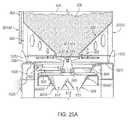
- FIG. 25Ais a fragmented perspective view of a container having proppant for fracking positioned on a conveyor according to an embodiment of a system and method of the present invention
- FIG. 25Bis an exploded perspective view of FIG. 5A of a container having proppant for fracking positioned on the conveyor according to an embodiment of a system and method of the present invention
- FIG. 25Cis a fragmented perspective view of a container having proppant for fracking positioned on a conveyor according to an embodiment of a the system and method of the present invention with portions of the container shown in break-away for clarity;
- FIG. 26Ais a fragmented perspective view of a conveyor hopper substantially full of proppant for fracking according to an embodiment of a system and method of the present invention
- FIG. 26Bis a fragmented perspective view of a conveyor hopper partially full of proppant for fracking according to an embodiment of a system and method of the present invention
- FIG. 26Cis a fragmented perspective view of a conveyor hopper without proppant according to an embodiment of a system and method of the present invention.
- FIG. 27Ais a fragmented perspective view of a conveyor belt having a plurality of partitions and a plurality of outside walls to convey proppant according to an embodiment of a system and method of the present invention
- FIG. 27Bis a fragmented perspective view of an alternative embodiment of a conveyor belt shown in FIG. 27A , having a plurality of partitions and a plurality of outside walls to convey proppant according to an embodiment of a system and method of the present invention
- FIG. 28Ais a fragmented perspective view of a second end of a conveyor according to an embodiment of a system and method of the present invention with a partial break-away view of the shroud for clarity further to show a conveyor belt;
- FIG. 28Bis a fragmented perspective view of a second end of the conveyor according to an embodiment of a system and method of the present invention with a partial break-away view of a chute for clarity further to show the second end of the conveyor belt depositing proppant into the chute by gravity feed.
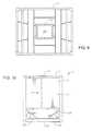
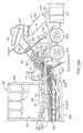
- FIG. 1shows an exemplary apparatus 1 for the transport and storage of proppant.
- the apparatus 1includes a container 2 .
- the container 2has a top wall 3 , a pair of side walls 4 and 5 and a pair of end walls 6 and 7 .
- the pair of side walls 4 and 5extend between the pair of end walls 6 and 7 .
- the container 2has a bottom discharge opening (not shown) located below the pair of side walls 4 and 5 and below the pair of end walls 6 and 7 .
- a hatch 8is hingedly mounted to the top wall 3 so as to cover an opening in the top wall 3 .
- the top wall 3is of a generally planar surface, though it will be understood that the top wall can include one or more surfaces positioned at various angles.
- the hatch 8is connected by hinges 9 to the top wall 3 .
- Latches 10 a and 10 bare used to secure the hatch 8 over the opening in the top wall 3 .
- the hatch 8will have a liner or gasket affixed therearound such that when the hatch 8 is in the closed position (as shown in FIG. 1 ), the hatch 8 will form a liquid-tight seal over the opening formed in the top wall 3 .
- the side walls 4 and 5 and the end walls 6 and 7define a rectangular configuration.
- a frame 10is configured around the exterior surfaces of the side walls 4 and 5 and the end walls 6 and 7 .
- the frame 10includes horizontal members 11 a and vertical members 11 b .
- the horizontal members 11 a and the vertical members 11 bform a cross-hatched configuration with respect to the side walls 4 and 5 and the end walls 6 and 7 .
- the horizontal members 11 a and the vertical members 11 bwere in the nature of square tubing that will bear against the outer surfaces of the respective walls.
- the frame 10contributes to structural integrity to the apparatus 1 . It can be seen that there are corner posts 12 , 13 , 14 , and 15 that are located at the corners between the side walls and the end walls. These corner posts 12 , 13 , 14 , and 15 enhance the structural integrity of the container 2 at the corners thereof.
- the container 12includes a bottom 16 .
- the bottom 16is in the nature of a rectangular structure. Suitable horizontal structural members extend between the corner posts 12 , 13 , 14 , and 15 at the bottom 16 .
- FIG. 1it can be seen that there is a ladder 17 that is affixed to the side wall 4 .
- the ladder 17is configured so as to extend vertically.
- the upper portion of the ladder 17will be adjacent to the top plate 3 .
- a workercan have easy access to the hatch 8 for purposes of opening or closing the hatch 8 .
- FIG. 2illustrates an example of the interior of the container 2 .
- the container 2can include corner posts 13 and 14 .
- the side wall 4will extend between the corner posts 13 and 14 .
- the top plate 3is mounted to a top of the corner posts 13 and 14 .
- the hatch 8is illustrated in its closed position on the top plate 3 .
- gussets 19 and 20serve to support end plates on respective surfaces 21 and 22 thereof.
- Each of the gussets 19 and 20has holes formed therethrough. The holes help reduce the weight of the gussets 19 and 20 while, at the same time, preserving the structural integrity of the gussets.
- a side plate 23is illustrated as extending toward the bottom 16 of the container 2 .
- the end plates and the side platesform a funnel adjacent to the bottom 16 of the container 12 .
- This funnelis directed toward a bottom discharge opening 24 at the bottom 16 .
- the angle of the side plates and end plateshelps to assure that the entire contents within the interior of the container 12 discharge through the bottom discharge opening 24 while, at the same time, assuring that a maximum amount of proppant can be contained within the interior volume of the container 12 .
- this volumewill be between 45,000 pounds and 48,000 pounds of proppant.
- the angle defined by the surfaces 21 and 22 of gussets 19 and 20 for the support of the end platescan be at an angle of greater than 25° with respect to the horizontal.
- the pair of end platescan extend in an angle of less than 37° with respect to the horizontal.
- the end platesextend at an angle of approximately 31° with respect to horizontal.
- the side plates 23also can extend at an angle of greater than 25° with respect to horizontal.
- the pair of side platescan extend at an angle of greater than 30° with respect to horizontal.
- each of the pair of side platesextends at an angle of 38° with respect to the horizontal. It was found that this configuration serves to assure that all of the proppant is discharged from the interior of the container.
- FIG. 2it can be seen that there are a pair of forklift sleeves 25 a and 25 b formed at the bottom 16 . As such, the forks of a forklift truck can be received within the sleeves 25 a and 25 b so as to allow a forklift truck to lift and to manipulate the container 2 .
- FIG. 3further illustrates aspects of the container 2 according to an embodiment of the invention.
- the end plates 26 and 27are illustrated as positioned on the surfaces 21 and 22 associated with the gussets 19 and 20 .
- the end plates 26 and 27are illustrated in a slightly curved configuration. As such, they form the funnel as used for the discharge of proppant.
- FIG. 3illustrates the side plate 23 as extending between the end plates 26 and 27 .
- Another gusset 28extends from the bottom 16 of the container 2 so as to provide structural support for the side plate 23 . It should be noted that the other side of container 2 can have a similar configuration.
- FIG. 3further shows the arrangement of the horizontal members 11 a and the vertical members 11 b that are arranged in a cross-hatched configuration against the sidewall 4 .
- Each of the vertical members 11 bextends between the top wall 3 and the bottom 16 .
- FIG. 4shows an end view showing the end wall 6 of container 2 .
- the end wall 6extends downwardly toward the funnel 29 located adjacent to the bottom 16 . Gussets 30 and 31 serve to support the side plates of the funnel 29 .
- the end wall 6also includes horizontal members 11 a and vertical members 11 b .
- the horizontal members 11 a and the vertical members 11 bare arranged in a cross-hatched configuration.
- the horizontal members 11 acan extend between the corner posts 12 and 13 .
- the vertical memberscan extend from the top wall 3 toward the bottom 16 .
- the opposite end of the container 2will have a similar configuration.
- FIG. 5shows the bottom structure 32 of the apparatus 1 according to embodiments of the present invention.
- the bottom structure 32includes the bottom discharge opening 24 .
- a rectangular-shaped reinforcing plate 33is affixed around the bottom discharge opening 24 so as to provide structural integrity thereto.
- FIG. 5further shows a pair of gussets 22 and 34 associated with one of the bottom plates. Another pair of gussets 21 and 35 is associated with the other end plate.
- a pair of gussets 36 and 37serves to support one of the side plates.
- a pair of gussets 38 and 39serves to support another of the side plates.
- a further supporting gusset structure 28is illustrated as extending between gussets 36 and 37 .
- gussets 36 and 37along with the gusset 28 , forms a rectangular structure for the support of the side plate thereon in a solid and stable configuration.
- gusset 40which extends between gussets 38 and 39 in spaced relation to the outer surfaces of the bottom structure 32 . This arrangement of gussets has been found to optimize the structural integrity of the side plates and end plates for the support of the heavy weight of the proppant within the interior of the container.
- FIG. 6is a further illustration showing an example of the bottom structure 32 of the apparatus 1 of embodiments of the present invention.
- gussets 36 and 37extend from a side 41 of the bottom structure 32 .
- the cross gusset 28is affixed to and extends between gussets 36 and 37 .
- the gussets 38 and 39extend from a side 42 of the bottom structure 32 .
- the cross gusset 40is affixed to and extends between gussets 38 and 39 .
- the gussets 22 and 34extend from a side 43 of the bottom structure 32 .
- gussets 21 and 35extend from an opposite side 44 of the bottom structure 32 .
- the structure in FIG. 6reinforces the strength of the container 2 in several respects.
- the arrangement of the square tubing of the corner posts 12 , 13 , 14 and 15provides strength at the corner of the container.
- the arrangement of the various vertical members 11 b and the horizontal members 11 afurther reinforces the strength of the frame 10 .
- the gussetsare arranged so as to be generally positioned centrally of each of the sides of the bottom structure. As such, in the area where strength is needed most, these gussets cooperate with the sides of the bottom structure so as to enhance the structural integrity.
- the use of the cross gussets 28 and 40further avoids deflection of the connected gussets so as further to reinforce the strength of the side plates residing thereon.
- FIG. 6it can be seen that there are receptacles 47 , 49 , 51 , and 53 formed at each of the corners of the bottom structure 32 .
- Receptacles 47 , 49 , 51 , and 53are configured so as to receive the pins associated with an underlying structure.
- the apparatus 1is suitable for being placed upon a support structure, such as a cradle.
- the pins on the support structurewill align with the receptacles 47 , 49 , 51 and 53 so as to assure that the container 2 is properly positioned over an underlying conveyor.
- the bottom discharge opening 24is assured of being positioned in a proper location.
- these receptacles 47 , 49 , 51 , and 53unexpectedly provide the combination of both accurate positioning of the container to upon the support structure while, at the same time, minimize the potentially toxic production of dust and silica particles during the release of proppant from the container 2 .
- FIG. 7illustrates an example of the top wall 3 of the container 2 of embodiments of the present invention.
- the opening 55is illustrated as formed in the top wall 3 .
- the opening 55can have a length dimension which is substantially greater than one-half of the length of the top wall 3 .
- the width of the opening 55is substantially less than the width of the top wall 3 .
- this elongated configuration of the opening 55assures that proppant can be discharged properly and quickly into the interior volume of the container 2 .
- the elongated nature of the opening 55avoids the problems of restricted openings, such as small portholes, that could be formed on the top wall 3 .
- the hatch 8can be placed over the opening 55 .
- the hatch 8can have an area slightly greater than the area of the opening 55 to assure that the contents of the container 2 are retained properly therein in a liquid-tight manner. As such, potential damaging effects of liquid penetration through the hatch 8 is effectively avoided. Furthermore, the placement of the hatch 8 over the opening 55 further avoids the release of potentially toxic dust and silica particles from the interior of the container 2 .
- FIG. 8illustrates an exemplary hatch 8 .
- the hatch 8has hinges 9 on one side thereof.
- a liner material 57is affixed around the periphery of the hatch 8 .
- This liner materialcan be of a rubber, elastomeric or polymeric material.
- FIG. 9illustrates an example of a bottom view of the container 2 according to an embodiment of the invention.
- the reinforcing plate 59is of an open rectangular configuration. As such, this reinforcing plate 59 enhances the structural integrity of the side plates and end plates during the discharge of proppant.
- a sliding gate mechanismcan be placed adjacent to the bottom discharge opening 24 so as to allow for the release of contents from the interior of the container 2 .
- FIG. 10is a side view of the apparatus 1 according to an embodiment and shows, in particular, a series of graduations 61 formed on the end wall 7 . These graduation 61 are indicative of the volume of proppant within the interior of the container 2 . Although the side walls and the end walls of the container 2 are opaque, the level of proppant within the interior of the container can easily be determined by tapping on the end wall 7 . The change in sound will correspond to a level of the graduations 61 . As such, the user is able to properly determine whether there is any proppant remaining within the container and whether all of the proppant has been discharged from the container.
- FIG. 10further shows the orientation of side plates 63 and 65 . The side plates 63 and 65 converge from the funnel 23 toward the bottom discharge opening 24 .
- the angle of the side plates and end platescontributes to avoiding the problems of retaining proppant within the interior of the container while, at the same time, allowing a maximum amount of proppant to be received within the container.
- the container 2will have a length of 118 inches and a width of 96 inches.
- the apparatus 1is particularly configured so as to be placed upon a railcar or on a trailer, though one skilled in the art, after reading this specification, will understand that other modes of transportation are permissible as well. In order to transport the apparatus 1 on highways, certain weight restrictions (as recited hereinabove) must be addressed. In order to comply with weight restrictions on roads, the container 2 should contain no more than 48,000 pounds of proppant.
- the total weight of the container 2 and the proppant thereinshould be no greater than 52,000 pounds. As such, it is necessary to configure the bottom structure, along with the end plates and side plates, such that approximately 48,000 pounds of proppant can be contained within the container. Experiments with various configurations and orientations of side plates and end plates have been carried out to determine the configuration of such side plates and end plates.
- the containerwas modified so that the side plates extended at a 20° angle to horizontal and the end plates extended at 25° angle of the horizontal.
- the total weight of such containerwas 5,420 pounds.
- the internal cubic capacity of such containerwas 554 cubic feet. As such, only an insufficient amount of proppant could be received in such a container.
- 4,120 pounds of proppantremained within the container. As such, this orientation of side plates and end plates was found to be ineffective in discharging all of the contents from the container. As a result, less than desired amount of proppant was available for use.
- the containerwas modified such that the side plate extended at an angle of 38° to horizontal and the end plate extended at an angle of 31° to horizontal.
- the total weight of such containerwas 6,200 pounds.
- a gross weight of the container with the sand thereinwas 52,000 pounds.
- the amount of sand within the containerwas 46,500 pounds.
- the internal cubic capacity of the containerwas 600 cubic feet.
- the amount of proppant within the containeri.e. 46,500 pounds
- was optimalIn other words, this amount of proppant satisfied that needs for proppant delivery while, at the same time, assured that the equipment used to transport such equipment complied with highway regulations.
- this arrangement of end plates and side platesoptimized the discharge of proppant while, at the same time, enhanced the capacity of the container to transport proppant.
- FIG. 11illustrates a configuration of the container 2 of the present invention with a gate 44 positioned at the bottom discharge opening 24 of the container 2 .
- the gate 44has a pair of pins 48 and 58 extending outwardly therefrom.
- the gate 44is shown in its closed position.
- An actuatorcan be used so as to move the gate 44 from the position shown in FIG. 11 in a direction toward either of the side walls 4 or 5 .
- Pins 48 and 58are illustrated as extending outwardly of the sides of the gate 44 .
- a suitable actuatorsuch as a hydraulic piston-and-cylinder arrangement, can be connected to these pins so as to achieve the requisite movement of the gate 44 from the closed position to the open position.
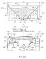
- FIG. 12is an end view showing an exemplary support structure 60 as used in embodiments of the proppant discharge system of the present invention.
- the support structure 60has a frame 62 which forms a top surface 64 , a bottom surface 66 , and sides 68 and 70 .
- the top 64 of the frame 62has a surface upon which the container 10 can be placed.
- Suitable pin connections 72 and 74extend upwardly from the top surface 64 so as to engage corresponding receptacles on the container 10 . These pins 72 and 74 can be utilized so as to assure that the container 10 is positioned properly upon the support structure 60 .
- a receptacle 76is positioned at or adjacent to the top surface 64 .
- the actuator 78is affixed to the frame 62 and extends to the receptacle 76 .
- the receptacle 76has a slot formed in the top end thereof.
- the slot of the receptacle 76is suitable for receiving one of the pins 48 and 58 of the gate 44 of the container 10 .
- the gate 44will be opened so that the proppant can be discharged through the bottom discharge opening 24 of the container 2 . Since pins 48 and 58 are symmetrically placed, and since the container 2 is rather symmetrical, the support structure 60 is particularly adapted to the variety of orientations with the container 2 can be placed upon the top surface 64 .
- FIG. 13there is a hopper 84 that is positioned below the top surface 64 .
- Hopper 84serves to receive a portion of the proppant as discharged through the bottom discharge opening 24 of the container 2 when the gate 44 is in the open position.
- the hopper 84can be utilized so as to properly meter the proppant onto the conveyor 86 (shown in FIG. 14 ).
- Conveyor 86is located below the opening 88 of the hopper 84 .
- hopper 84has an opening 88 of a generally inverted V-shaped configuration.
- metering gate 90that is mated with the opening 88 and also has a V-shaped configuration. The metering gate 90 can be moved a small distance so as to allow for the selected and controlled discharge of proppant from the hopper 84 onto the conveyor 86 .
- FIG. 14shows the interior of the hopper 84 .
- Hopper 84includes side walls 92 and 94 and end walls 96 and 98 (shown in FIG. 13 ).
- the walls 92 , 94 , 96 and 98are formed into a funnel-like shape so as to move the proppant downwardly toward the metering gate 90 .
- the opening 88 of the hopper 84has a plurality of slots formed therein.
- the metering gate 90has a plurality of slots formed therethrough.
- the structures between the slotsare substantially solid. As such, when the slots of the metering gate 90 are aligned, with the slots of the opening 88 , then proppant can be discharged onto the underlying conveyor 86 .
- a small movement of the metering gate 90 in one direction or another,will block the flow of the proppant through the slots of the opening 88 of hopper 84 .
- very small actuators 100 and 102can be used so as to achieve the proper metering of the proppant onto the conveyor. If a low flow rate of proppant is desired, then the actuators 100 and 102 will move the metering gate 90 only a small distance. If a greater flow rate is required, then the actuators 100 and 102 will move the metering gate 90 so that the slots of the metering gate 90 fully correspond with the slots of the opening 88 so as to achieve a maximum flow of proppant from the hopper 84 down to the conveyor.
- FIG. 15shows the container 2 as placed upon the top surface 64 of the support structure 60 .
- a forkliftcan be utilized so as to properly position the container 2 in a proper position upon the pins 72 and 74 of the support structure 60 .
- the gate 24 of the container 2will be closed.
- the metering gate 90can also be closed.
- the gate 44can be moved to an open position so that the proppant is discharged into the hopper 84 .
- the hopper 84can then be filled with proppant.
- the metering gate 90can be opened so as to achieve the desired flow rate of proppant through the opening 88 of the hopper 84 .
- FIG. 16shows a side view in which the container 2 is placed upon the top surface 64 of the support structure 60 .
- the conveyor 120is illustrated as extending longitudinally. As such, when the proppant passes through the metering gate 90 associated with the hopper 84 , any proppant within the interior volume of the container 2 can be delivered, in a controlled manner, onto the conveyor 120 .
- FIGS. 16 and 17illustrate exemplary containers 110 , 112 , 114 and 116 as placed upon the support structure 118 .
- the support structure 118has a sufficient length so as to accommodate the containers 110 , 112 , 114 and 116 .
- the conveyor 120is arranged beneath the top surface of the support structure 118 and below the respective hoppers 122 , 124 , 126 and 128 below the respective containers 110 , 112 , 114 and 116 .
- the conveyor 120is an endless conveyor that is suitably wound around sheaves and idlers so as to travel a desired path.
- the proppant that is discharged from the containers 110 , 112 , 114 and 116is discharged onto the conveyor 120 so as to travel therealong and along upwardly extending section 130 .
- the end 132 of the conveyor 120will open to a chute 134 .
- the chute 134can be directed toward the desired purposes at the fracturing site.
- the array of containers 110 , 112 , 114 and 116can be configured so as to replace existing storage facilities at the fracturing site.
- the support structure 118 , along with the conveyor 120can be easily transportable by a truck upon a roadway because of the use of the wheels 136 .
- the forward end 138can be suitably connected to a truck so as to allow for the easy transport of the system of the present invention.
- FIG. 17illustrates an exemplary placement of the containers 110 , 112 , 114 and 116 upon the support structure 118 .
- the end 138includes a suitable hitch connection for attachment to a truck.
- the conveyor 120extends below the containers 110 , 112 , 114 and 116 so as to deliver the proppant to the chute 134 .
- the chute 134is suitably pivotable in cooperation with the end 132 of the conveyor 120 so as to allow for the controlled and directed discharge of the proppant to the desired location.
- the container 2is manufactured as a single unit.
- the gate 44 of the container 2is specifically engineered to align with the actuator 78 located on the conveying system, as will be discussed more thoroughly below.
- the actuatoris hydraulically controlled and accepts the pin 48 which is attached to the gate 44 .
- the gate 44moves horizontally so as to allow for the discharge of proppant therefrom.
- the containercan be specifically applied for transport via rail.
- the railcarcan be designed so as to accommodate up to four containers 2 .
- the railcarcan carry approximately 180,000 pounds of proppant when the four containers are placed on the railcar.
- the railcarcan be similar to current inter-modal railcars that carry twenty foot, forty foot and fifty-three foot inter-modal containers.
- the railcarwould include typical inter-modal load-locks which are evenly spaced down to chassis of the railcar.
- the containershould be constructed of materials wide enough to keep the overall loaded weight of the container under currently regulated railroad weight guidelines. Additionally, it must be strong enough to bear the load of the loaded container. This development allows sand mines to load proppant directly into a container 2 to speed up the loading process. It also eliminates the need to build a silo storage at the mine site. Once the container arrives at its designated location or region, trans-load processes to pneumatic trailers, silos or flat storage, are thus eliminated.
- embodiments of the inventioninclude improved delivery system that can be used at the well-site.
- the support structure 60includes a fabricated steel frame upon which multiple containers can be positioned.
- the containerslock into receptacles that secure the containers to the frame.
- the containerwill then sit above a conveying system that delivers the proppant from the container as the gate is opened to a master-conveying belt.
- the cradleis outfitted with a hydraulic system which can control the opening and closing of the gates.
- the containers of embodiments of the present inventioncan be combined as an attachment or cartridge compatible with existing devices known as SAND KINGSTM, SAND CHIEFSTM and SAND DRAGONSTM. By replacing existing hoppers on these devices with the removable containers of the present invention, even greater efficiencies can be attained in the proppant delivery process.
- the conveying system of embodiments of the present inventionis an alternative method of delivering proppant from the container to the blender belt for the mixing unit once delivered to the well-site.
- the conveying system of the present inventionprovides all of the functionality commonly seen in the SAND MASTERTM, SAND KINGTM, SAND DRAGONTM, SAND MOVETM, etc. As such, embodiments allow the flow of sand to be metered onto the conveyor belt through a hydraulic system of flow gates.
- the containerfirst is lifted into position onto the support structure.
- the bottom flow gateis received by the receptacle of the hydraulic actuator so as to create a lock between the pin of the gate and the hydraulic system.
- the hydraulic systemthen opens the flow gate and the proppant so as to gravity-feed into a hopper located on the support structure.
- Another set of flow gates associated with the hopper systemare then opened by way of another hydraulic system. This allows the proppant to be metered and to flow onto a conveyor belt.
- the conveyor beltthen can deliver the proppant to the blender or the T-Belt.
- the proppantthen can be mixed with other materials in the blender.
- a total of four (4) empty containerscan be returned by a single flatbed trailer. This provides a 4:1 level of efficiency in removing the containers from the well-site. Additionally, a forty foot container chassis can be used in the movement of both empty and full containers.
- the support structurejust like the containers, can be delivered to the well-site by a typical flatbed truck. The support structure could be towed via truck to the site in manner similar to any other trailer.
- embodiments of the inventionemploy the ten-foot ISO containers, there is a small footprint for the ISO containers relative to the capacity of sand that they can store.
- the containersWhen the containers are stacked three high, the containers can store approximately 135,000 pounds in a footprint of eighty square feet.
- the available space at the wellhead, and in potential proppant trans-loading facilities,can be extremely limited. As such, embodiments lessen the footprint that is required for a given amount of proppant at such a location.
- Proppantcurrently is delivered to the frac site via pneumatic trailers. Pneumatic pressure is used to pressurize the trailer and then “blow” the material into a sand storage unit. This process creates an immense amount of particulate matter than can then be inhaled by personnel at the frac-site. Additionally, while blowing the sand into the sand storage facility, the sand storage facility must vent the pressurized air to the atmosphere. This creates an even greater exposure to particulate matter. The constant need to take delivery of proppant on-site creates a constant environment of dust and small particles in the air.
- embodimentseliminate pneumatic deliveries, methods significantly reduce the amount of particulate matter at the frac site.
- the gravity-feed delivery method from the container to the blendergreatly improves the safety of well-site personnel.
- embodimentsreduce trucking emissions by reducing the amount of trucks that are being used or waiting. The safety at the wellhead is improved by reducing such truck traffic.
- FIG. 18Shown in a side view in FIG. 18 are examples of containers 310 for housing, shipping, and distributing a flowable material, such as proppant used in wellbore operations.
- the containers 310 shown in FIG. 18can be, for example, structured substantially similarly to container 2 discussed elsewhere in the specification, including with reference to FIG. 1 for example. The same is true for containers 110 , 112 , 114 , and 116 discussed with reference to FIGS. 16 and 17 .
- FIGS. 18 and 19Applicant makes reference to container 310 .
- the containers 310are shown set onto a railcar 312 for transportation along a railway (not shown).
- Each of the example containers 310includes a frame 314 that includes upper joists 316 , which are elongate members shown joined end-to-end to define a rectangle at an upper end of frame 312 .
- the containers 310are box-like members having side surfaces and an upper surface, and where the surfaces generally are rectangular and planar.
- Lower joists 318similar to upper joists 316 , are shown disposed axially away from upper joists 216 .
- Elongate vertical posts 320connect to the upper and lower joists 316 , 318 at corners formed where the members of the joists 316 , 318 join end to end.
- Planar sidewalls 322span across the space formed between the adjacent joists 316 , 318 and adjacent posts 320 . In the example of FIG. 18 , adjacent sidewalls 322 join at their respective vertical edges.
- vertical support ribs 324shown extending along the outer surfaces of the sidewalls 322 between the upper and lower joists 316 , 318 ; ribs 324 are laterally spaced apart from one another and the posts 320 .
- Horizontal support ribs 326are depicted that horizontally extend between adjacent posts 320 and that are vertically spaced apart from one another. In the example of FIG. 18 , the horizontal support ribs 326 are disposed generally transverse to the horizontal support ribs 324 , and are set between the vertical support ribs 324 and the sidewalls 322 .
- Support ribs 324 , 326are elongate members that are laterally spaced apart from one another and in an example provide structural support for the sidewalls 322 and resist radially projecting outward forces resulting from flowable material, such as proppant, contained within the sidewalls 322 .
- a lower end of the frame 314includes a girder 328 , which includes a series of elongate members that are joined end-to-end to form a generally rectangular assembly.
- the lower ends of the posts 320connect to the girder 328 at corners of the girder 328 defined where the members are joined.
- the girder 328is spaced axially away from the lower joists 318 on a side opposite from the upper joists 316 .
- Lower ends of the sidewalls 322terminate at the lower joists 318 thereby defining a space 329 between the lower joists 318 and girder 328 .
- Vertical beams 330are provided along the periphery of the space 329 and which extend vertically between the lower joists 318 and girder 328 .
- a lower wall 332Connected to the lower ends of the sidewalls 322 is a lower wall 332 , which slopes downward with distance away from the sidewalls 322 to create a generally frusto-conical configuration.
- the combination of the sidewalls 322 and lower wall 332define a container 333 for the storage and transportation of flowable material, e.g. proppant and the like.
- An opening, discussed aboveis optionally formed axially through the lower wall 332 for allowing material to flow from the container 333 .
- An optional hatch, discussed above,is provided in the opening for selectively dispensing material contained from within the container 333 .
- Support webs 334are shown disposed in the space 329 and at angular locations around an axis A X of the container 333 and that provide support for the lower wall 332 .
- Upper surfaces of the support webs 334depend axially downward with distance away from the sidewalls 322 along a path complementary to the slope of the lower wall 332 .
- the support webs 334are generally planar and have elongate sides oriented generally vertically, and which extend radially from axis A X .
- Further illustrated in FIG. 18are openings formed laterally through the girder 328 that define slots 336 , and which selectively receive tines of a forklift therein so that the containers 310 can be lifted and moved, such as to and from the railcar 312 .
- Example materials for the components of the containers 310include metals, metal alloys, composites, and combinations thereof.
- the example of the railcar 312 illustratedis what is commonly referred to as a “spine car”, and which includes an elongated spine member 340 oriented along the length of the railcar 312 . Further included with the railcar 312 are forward and rear wheels 342 , 344 shown mounted to a lower surface of the spine member 340 so the railcar 312 can negotiate along rails. Forward and rear couplers 346 , 348 are illustrated provided respectively on the forward and aft ends of the spine member 340 and for coupling to other railcars. As shown, a height of the spine member 340 increases at a mid-section 350 of the spine member 340 .
- Reinforcing structures 351 1 , 351 2 , 352are strategically located on the spine member 340 at locations where the height of the spine member 340 increases, and approximately at a center of the spine member 340 .
- the reinforcing structures 351 1 , 351 2 , 352span the length of the spine member 340 where adjacent mounting posts 338 are disposed.
- FIG. 19illustrates in a plan view an example of the railcar 312 without the containers 310 ( FIG. 18 ) mounted thereon.
- different positions of the forward wheels 342are illustrated in phantom view and depict a pivotal range of motion of the forward wheels 342 .
- bolsters 353are shown mounted on an upper surface of the spine member 340 , where the bolsters 353 extend generally transverse to the spine member 340 and project outward past the lateral sides of the spine member 340 .
- Bolsters 353each include an elongate cross beam 354 that transversely couples to the spine member 340 and which provides structural support on which the containers 310 are selectively mounted.
- Optional top plates 356mount on an upper surface on opposing ends of each cross beam 354 , and on a side opposite the spine member 340 .
- Each top plate 356 as illustratedis generally planar, and has a width that increases at a distance away from opposing ends of each cross beam 354 .
- the wider and narrower portions of the top plates 356are wider than the cross beam 354 .
- the top plates 356 on each cross beam 354are spaced laterally away from one another.
- the mounting posts 338attach to upper surfaces of the top plates and are located proximate the outer terminal ends of the cross beams 354 .
- Additional bolsters 358are shown on the spine member 340 , and which are proximate to opposing ends of the spine member 340 .
- Bolsters 358each include an elongate beam 360 mounted to the spine member 340 and oriented generally transverse to the spine member 340 ; where opposing ends of the beam 360 extends outward past lateral sides of the spine member 340 .
- the beam 360has a generally consistent width along its length.
- a top plate 362is provided on the beam 360 and on which mounting posts 338 are attached.
- FIG. 19shown in a side view is an example of an end of bolster 353 taken along lines 3 - 3 .
- beam 354has a vertical thickness that increases proximate its attachment to spine member 340 , thereby enhancing structural support for mounting cargo thereon.
- a receptacle 364that projects axially through an end of beam 354 and that selectively receives the mounting posts 338 .
- FIG. 21shows in side view an example of an end of bolster 358 taken along lines 4 - 4 .
- bolster 358has a generally constant thickness along its length, and includes a receptacle 366 proximate its terminal end.
- landingsare provided on opposing ends of the spine member 340 and past bolters 348 .
- Grates 368 , 370are provided on the landings for supporting operational personnel when on the railcar 312 .
- the containers 310have sides with a length of about 310 feet in length and are about 10 feet in height.
- the railcar 312has a gross rail load of 263,000 pounds.
- An example design specification of the railcar 312is provided in “AAR Specifications for Design, Fabrication, and Construction of Freight Cars, M-1001”, which is incorporated herein in its entirety.
- limiting dimensionsare designed to AAR Plate B.
- the railcar 312is designed to comply with AAR Interchange Rules and D.O.T. requirements and hast light weighing and stenciling requirements of AAR Interchange Rule 70.
- parts of the railcar 312are made and assembled using gauges and templates for interchangeability.
- Truck castingscan be 110-ton, 16′′ center bowl, and spring grouping suitable for a 286,000 pound gross rail load in accordance with AAR M-976. However, trucks can be sprung for 263,000 pound gross rail load.
- Side framescan be AAR M-201 Grade B+ cast steel in accordance with AAR Specifications M-203 and M-210.
- the side framescan be narrow pedestal type and have integral unit brake beam guides.
- Column guidescan have wear plates secured with SAE J429 Grade 8 fasteners.
- Bolsterscan be AAR M-201 Grade B+ cast steel in accordance with AAR Specification M-202 and M-210, with 13 ⁇ 4 inch ⁇ 16 inch finished bowl, with 2 inch welded steel vertical wear ring, designed for loose manganese steel or polymer horizontal wear plate.
- the center plate bearing surfacecan be machined.
- Roller bearing adapterscan be for 61 ⁇ 2′′ ⁇ 9′′ Class K bearings and narrow pedestal side frames. Examples exist without heat indicators.
- the thrust shoulderscan be hardened.
- Roller bearingscan be NFL type for 61 ⁇ 2′′ ⁇ 9′′ journals.
- Axlescan have a nominal 100-ton capacity with 61 ⁇ 2′′ ⁇ 9′′ journals, in accordance with AAR Specification M-101, latest revision, Class K, Grade F.
- Wheels in an exampleare 36′′, AAR H-36 or CH-36, one wear, Class C.
- Side bearingscan be constant contact metal cap long travel type, and optionally attached to bolster with SAE J429 Grade 8 bolts and IFI-100 Grade C locknuts.
- Center pins in an exampleare 13 ⁇ 4′′ diameter A36 steel.
- the center sillis a fishbelly box type with the bottom cover plate at the center is 1 ⁇ 2 inch ASTM A572 GR50 steel with Charpy V-notch 15 ft-lb at ⁇ 20° F.
- the bottom cover plate at the endscan be 3 ⁇ 4 inch ASTM A572 GR50 steel with Charpy V-notch 15 ft-lb at ⁇ 20° F.
- the top covercan be 7 ⁇ 8 inch ASTM A572 GR50 steel from striker to striker.
- the webs at the endsare 5 ⁇ 8 inch ASTM A572 GR60 steel with Charpy V-notch 15 ft-lb at ⁇ 20° F.; and the webs in the center are 5/16 inch ASTM A572 GR50 steel.
- Center sill separators at pedestalscan be 1 ⁇ 2 inch ASTM A572 GR50 steel plate.
- Body bolsters in one exampleare built-up welded design consisting of double webs of 3 ⁇ 8 inch ASTM A572 GR50.
- Top cover platesare optionally 3 ⁇ 8 inch ASTM A572 GR60 steel with a Charpy V-Notch value of 15 ft-lb at ⁇ 20° F. and extend just past the truck side bearings.
- bottom cover platesare of 3 ⁇ 8 inch ASTM A572 GR50.
- Bolster tie platescan be ASTM A572 GR50 steel, welded to bottom cover plates and center sill flanges.
- web stiffenersare ASTM A572 GR50 steel located at critical changes in section on bolsters.
- Pedestalscan be at three locations per car, are built-up weld design, with 5/16 inch ASTM A572 GR50 steel pedestal webs welded to center sill and pedestal end plate. Pedestals are optionally cantilevered off of the center sill.
- pedestal top cover platesare 3 ⁇ 8 inch ASTM A572 GR50 steel and extend from pedestal end plate to center sill top cover plate and are welded to pedestal webs and top of center sill.
- Pedestal bottom cover platescan be 3 ⁇ 8 inch ASTM A572 GR50 steel and extend from center sill web to pedestal end plates and are welded to crossbearer webs.
- Pedestal Top cover platecan be reinforced with 5 ⁇ 8 inch ASTM A572 GR50 in the area where the IBC connectors connect the container to the pedestal.
- crossties two per carare provided that are fabricated from 3 ⁇ 8 ASTM A572 GR50 steel extending from center sill web to end sill, and which are welded to center sill and end sill webs and flanges.
- End sillscan be formed from 5/16 inch ASTM A572 GR50 steel and are welded to center sill and crossties.
- Body side bearingsare optionally provided that are 5 inch wide of forged steel to Brinell hardness 277-341 and are secured to steel fillers and bolster bottom cover plates with two (2) 3 ⁇ 4 inch Grade 8 square neck plow bolts, ASTM F-436 hardened washers and ASTM A563 Grade C hex nuts, torqued to 300 ft-lbs.
- Nutcan be tack welded to bolt after torquing.
- Pedestalscan be reinforced for jacking fully loaded car off the trucks.
- Couplerscan be bottom operating AAR EF511CE Reduced Slack of Grade E steel.
- coupler release riggingis standard for bottom operating coupler, and yokes can be SY45AE of Grade E steel.
- Draft gear carrierscan be lockbolted to center sill, and draft gears can be AAR M-901E with Y44 followers.
- design and installation of the brake systemis in accordance with AAR Standards S-400, S-401, S-475 and AAR Field Manual Rule 88 A.2.r; and can be tested in accordance with AAR Standard S-486.
- the carcan be equipped with one 40% empty load device with downstream proportioning valve.
- Extra strong steel pipemay be used for all piping except for short nipples which are Sch 40.
- Pipingcan be secured to underframe of car with wedge type pipe anchors. In an example, maximum unsupported span is 8′-0′′.
- Individual pipescan be formed to accurate shape before application to car.
- Pipe connectionscan be made with either adjustable (swivel) socket welded fittings or all welded couplings. In angle cock embodiments, connections can be screw type.
- Branch pipe teecan be an all-welded application for 11 ⁇ 4′′ pipe and bolted flange fitting for 1′′ pipe.
- Braking ratiocan be in accordance with D.O.T. requirements and AAR Interchange Rules.
- Example brake shoesare two inch (2′′) high-friction composition type, AAR H-4 designation.
- Example brake beamsare AAR Standard No. 24, angle corrected, with metal shoe rejection lugs.
- brake pinsare C1050 steel turned or drop forged and induction hardened to Rockwell C60-63 to a depth of 0.080′′-0.100′′, where minimum diameter of pins can be 1 3/32′′.
- Brake pinscan be secured with 3 ⁇ 8′′ standard cotter keys.
- Brake shoe keyscan be forged steel spring type.
- Further example embodimentsinclude truck levers and connections that are forged steel design.
- Body leverscan be fabricated by car builder from 1′′ flame cut ASTM A36 steel.
- Example brake rodsare 7 ⁇ 8 inch diameter ASTM A36 steel and brake rod supports can be the closed loop design equipped with non-metallic wear protectors.
- An example stainless steel badge plateis provided at one per car, showing brake lever dimensions and cylinder size is applied to car in a visible location near air brake cylinder.
- Ball type angle cockscan be used that are threaded onto a nipple which is secured to brake pipe with a socket weld by screwed coupling.
- An example release rodhas a 1 ⁇ 2 inch diameter ASTM A36 steel with closed loop ends and arranged for in-line operation of the brake cylinder release valve.
- Brake reservoircan be an all welded fabricated design.
- Brake beam wear platescan be all metal type UW-116.
- Safety appliancescan comply with AAR and FRA requirements and the first car may be inspected by an FRA inspector.
- Handholdscan be 3 ⁇ 4′′ round bar forgings of ASTM A576 GR1015 steel.
- Ladderscan have handholds fastened to L2 ⁇ 2 ⁇ 3/16 ASTM A36 steel stiles with 5 ⁇ 8 inch fasteners.
- Ladder assembliescan be fastened to car body with lockbolts or threaded bolts and nuts as applicable.
- Sill stepscan be 1 ⁇ 2 inch ⁇ 2 inch ASTM A36 steel and optionally located at each corner of car and fastened to side sill with 5 ⁇ 8 inch fasteners.
- End platformsare in one example 191 ⁇ 2′′ ⁇ 100′′ and are mounted on both ends of the car.
- Steel surfacescan be cleaned free of rust, scale, dirt, grease, and moisture.
- the sides, ends, and underframescan be blasted to a commercial quality finish (SSPC SP-6) before painting. Air valves, hand brakes, slack adjusters, etc., are optionally not removed during blasting but are adequately protected.
- Metal-to-metal lap joints or surfaces which are inaccessible and open to the atmosphere after assemblycan be painted with weldable primer before assembling. Exterior surfaces of sides and ends can be painted with waterborne acrylic emulsion, four mils minimum dry-film thickness. All paints can be lead free in accordance with Gunderson paint specifications for all railcars.
- the reporting marks and car numberscan be steel stamped on the BL side of the center sill inboard of the no. 2 axle and on the side sill at the BR corner of the car. Stenciling can be in accordance with AAR Manual of Standards and Recommended Practices, Section “L”, and the customer's requirements and can be based on 263,000 pound gross rail load. Adhesive backed decals can be manufactured in accordance with AAR Specification M-947. Trucks, as received from truck manufacturer, can have one (1) coat of primer and can be stenciled with customer's reporting marks and car number on the right hand tension member of the side frames. Route card boards, two per car, can be all metal type welded to the car side. Route card boards can be painted same color as exterior car body.
- Railcar 12can be equipped with two (2) AEI (Automatic Equipment Identification) tags.
- Bolts and nutscan be threaded to coarse thread series in accordance with the Unified Screw Thread Standard Class 2A External and Class 2B Internal Threads for Class 2 fit of the American Standard for Screw Threads.
- Bolt headscan be in accordance with American Standard Regular Hexagon.
- Nutscan be American Standard per ASTM Specification A563 GR A or stronger, unless otherwise specified.
- High-strength boltscan be ASTM Specification A325 or stronger, unless otherwise specified.
- Self-locking nuts meeting AAR Specification M-922can be used on bolts securing control valve, combined reservoirs, brake cylinder, retainer valve, and angle cock “U” bolts to car body supports.
- Self-locking cap screws meeting AAR Specification M-922can be used for securing all flanged pipe fittings on reservoir, ABDW valve, brake cylinder and retainer valve. Riveting and lock bolting applications can be in accordance with Chapter V of the AAR Manual of Standards and Recommended Practices, Section C-Part II. Welding practice can be in accordance with Chapter V of the AAR Manual of Standards and Recommended Practices, Section C-Part II.
- the proppant delivery system 210includes a track 212 formed in the nature of a circuit.
- a container-hauling trolley 214is movably positioned on the track 212 .
- a proppant supply station 216is positioned on the track 212 .
- the container-hauling trolley 214is movable along the track 212 to a location below the proppant supply station 216 .
- a proppant discharge station 218is positioned adjacent to another portion of the track 212 .
- the container-hauling trolley 214is movable on the track to a location adjacent to the proppant discharge station 218 .
- a proppant transport pathway 220extends in spaced relationship to the track 212 .
- a crane 222has a portion adjacent to the proppant discharge station 218 and another portion adjacent to the container transport pathway 220 .
- the crane 222is suitable for moving a proppant container from the proppant discharge station 218 toward the container transport pathway 20 .
- the craneis a gantry crane 224 .
- the gantry crane 224has one portion located directly above the proppant discharge station 218 and another portion located above the container transport pathway 220 .
- the container transport pathwayis illustrated in FIG. 22 in the form of a road.
- a plurality of trucks 226 and 228are movably positioned on the container transport pathway 220 .
- the trucks 226 and 228are movable between a location below the gantry crane 224 to a location at a well that uses the proppant from the proppant container.
- Truck 226is illustrated as having a container 230 positioned thereon.
- the proppant supply station 216includes a plurality of silos 232 , 234 and 236 that are arranged above a loading bay 238 .
- the loading bay 238is positioned over the track 212 .
- Various trolleys 214are illustrated as passing through the interior of the loading bay 238 .
- Each of the trolleys 214includes a plurality of containers thereon.
- Each of the containers on the trolleys 214will open at the upper end thereof.
- proppant in the silos 232 , 234 and 236can be directed, by gravity discharge, the into each of the proppant containers on the trolleys 214 .
- a conveyor 240can extend from a location away from the track 212 toward the upper end of each of the silos 232 , 234 and 236 .
- conveyor 240can be utilized so as to deliver bulk amounts of dry proppant into the silos.
- the proppantcan be stored in the silo for as long as required.
- the trolley 214can move along the track 212 so as to move into the loading bay 238 .
- the silos 232 , 234 and 236can then be opened so as to deliver proppant into each of the containers on the trolleys. After the containers are filled, they can move along the track 212 toward the proppant discharge station 218 .
- the conveyor 240will transfer the dried proppant from a drying process and a grain separation process toward the silos. As such, the processes proppant is rapidly containerized so as to avoid any damaging exposure to the elements.
- FIG. 22It can be seen in FIG. 22 that there is another proppant discharge station 242 that is provided.
- the gantry crane 244has one portion that overlies the track 212 and another portion that overlies the container transport pathway 220 .
- the gantry crane 244can suitably lift a container from the trolley 214 and either move the trolley to a location on the earth 46 or to a location on top of another container on the inventory stack of containers 248 .
- the gantry crane 244can also be used so as to move the empty container 230 from the truck 226 onto an inventory stack of empty containers 250 . It can also be used so as to place such a container on to the earth.
- the area beneath the gantry cranes 224 and 244will include an inventory stack of proppant-filled containers 244 and an inventory stack of empty containers 250 .
- the inventory stack of filled containers 248and is located adjacent to the track 212 .
- the inventory stack 50 of empty containersis illustrated as located closer to the container transport pathway 220 .
- these inventory stacks 248 and 250can be interchangeable depending on the desires and requirements of the particular system employed.
- the proppantafter it is mined, dried and grain sized separated, can remain stored in the inventory stack 250 so as to avoid exposure to the elements.
- the truck 226is utilized for the delivery of empty proppant containers. As such, there is an empty container 230 located on a forward portion of the bed of the chassis of the truck 226 and empty container 252 located on a rearward portion of the chassis of the truck 226 . Because the containers 230 and 256 are empty, the truck 226 can be utilized so as to haul a pair of containers, and possibly more containers. Once the container is filled, however, the truck 228 will have the container 258 positioned forward of the rear wheels of the bed of the chassis of the truck 228 . As such, truck 228 can be utilized so as to deliver a filled container to a well site.
- the chassis of truck 228can be of a type described in U.S. Design Pat. Nos. D694,670 and D688,597. This chassis was further described in co-pending U.S. patent application Ser. No. 13/854,405, to the present application.
- These gantry cranes 224 and 244can span significant distances. As such, they can be configured so as to extend for the distance between the track 212 and the container transport pathway 20 . Additionally, each of the gantries 224 and 244 is supported on wheels. As such, they can be suitably moved so as to grasp any of the containers in the stacks 248 and 250 therebelow. If necessary, the gantry 244 can be utilized so as to remove and stack empty containers into the stack 250 . The gantry 224 can be utilized so as to move filled containers into the inventory stack 248 . The gantry 224 can further be utilized so as to remove a filled container from the trolley 214 at the discharge station 218 and to move the container from the trolley 214 to the inventory stack 248 of filled containers.
- the gantry 224could also be utilized so as to remove an empty container 230 from the chassis of the truck 226 so as to place such a container on the inventory stack 250 of empty containers.
- each of the gantries 224 and 244can be configured or interchanges so as to carry out any or all of the above operations.
- a single gantrycould be utilized for all of the purposes intended herein.
- FIG. 22it can be seen that there is a railroad track 260 that is positioned adjacent to the container transport pathway 220 .
- the railroad tracks 260have a plurality of railcars 262 rollably positioned thereon.
- each of the railcars 262can be utilized so as to carry containers 264 on the bed thereof.
- This type of railcarwas shown in U.S. Design Pat. No. D703,585 to the present applicant.
- either the gantries 224 and 244can be suitably moved, or the railcars can be moved, so that either the filled containers can be placed on the railcars or the empty containers can be removed from the railcars.
- the gantry 244can be utilized so as to lift an empty container from the railcar and place such an empty container on the inventory stack 250 .
- the gantry 244also can be utilized so as to move such an empty container from the inventory stack 250 to a trolley 214 .
- the containerwould be suitable for movement by the trolley 214 to a location within the proppant supply station 216 .
- the gantry 224could be utilized so as to remove the filled container from one of the trolleys 244 and place the filled container on the inventory stack 248 .
- Gantry 224can also be utilized so as to remove the filled container from the inventory stack 48 and to place the container onto the railcar 262 .
- the container transport pathway 220can be utilized for either the delivery of empty proppant containers and/or for the delivery of filled proppant containers to the well site. If necessary, separate pathways could be utilized for the purpose of delivery of the empty proppant containers and for the delivery of filled containers.
- the railroad tracks 60can be utilized either for the delivery of empty proppant containers or delivery of filled proppant containers to the well site. Additionally, or alternatively, a separate rail line 60 could also be used for these alternate purposes.
- FIG. 23is another view showing the operation of embodiments.
- the system 210includes a track 212 .
- the track 212is in the form of a circuit which extends from the proppant supply station 16 to the proppant discharge stations 218 and 242 .
- Each of the trolleys 214is illustrated as positioned on the track 212 .
- the arrow 270illustrates the direction of travel of the trolleys 214 .
- the trolley 272 having an unfilled containertravels along the track 212 so as to enter the loading bay 238 . Proppant is discharged from the silos of the proppant supply station 216 into the empty containers on the trolley 272 .
- trolley 272can move along the track 212 so as to enter the proppant discharge station 242 .
- the gantry 244can be utilized so as to lift the filled proppant containers from the trolley 272 and place the proppant containers on the inventory stack 248 .
- a proppant processing plant 271is shown.
- the proppant processing plant 271will process the raw proppant, dry the proppant, and separate proppant in accordance with grain size and quality.
- the processed proppantis delivered to a pile 276 along a conveyor 273 .
- the raw proppant pile 274is shown also in FIG. 23 . This raw proppant can be transported to the proppant processing plant along another conveyor.
- the processed proppant pile 276is positioned adjacent to the track 212 .
- Conveyor 240is utilized so as to deliver the processed proppant into each of the silos 216 .
- the processed proppantcan further be dried in the silos 216 .
- the raw unprocessed proppant pile 274can be delivered to a location adjacent the proppant processing plant 271 .
- FIG. 23there are piles of proppant 274 and 276 that have been created at the mine site in a location adjacent to the track 212 .
- Conveyor 240is utilized so as to deliver the bulk proppant from the piles 274 and 276 into each of the silos 216 .
- the bulk proppant 274 and 276can be delivered by railcars to such a location.
- FIG. 23further shows a truck 278 .
- Truck 278has empty proppant containers 280 and 282 on the chassis thereof. Once again, because the containers 280 and 282 are empty, the truck 278 can be utilized for the purpose of delivering more than one empty proppant container.
- the gantry 224is utilized so as to remove the empty containers 280 and 282 from the chassis of the truck 278 and to place such empty containers on the inventory stack 250 of empty containers. Truck 78 will then have an empty chassis. Truck 278 can then moved to the proppant discharge station 242 such that the gantry 224 can load a filled container of proppant from the inventory stack 228 onto the bed of the chassis of the truck.
- Truck 278is now illustrated as having a filled container 284 positioned on the bed of the chassis of the truck. Since the filled container 284 is extremely heavy, the truck 278 is only capable of transporting a single container. This filled container is illustrated as located centrally on the bed of the trailer forward to the rear wheels. Truck 278 is then illustrated as moving along the road 86 toward the mine with a filled container of proppant.
- FIG. 23further shows that there is a railcar 290 with several empty proppant containers thereon.
- the gantry 224can be utilized so as to remove the empty container from the railcar 290 and place such an empty container on the inventory stack 50 .
- the railcarthen can moved to the discharge station 242 such that the gantry 244 can place a filled container of proppant from the inventory stack 248 onto the bed of the railroad car 290 .
- the railroad car 290can then move along the track 292 toward an intended destination.
- each of the gantries 224 and 244can be utilized so as to deliver an empty proppant container from a vehicle on the roadway 220 directly to the trolley 214 .
- each of the gantries 224 and 244could be utilized so as to deliver a filled container of proppant from the trolley 214 directly onto the bed of the chassis of the truck or the bed of the railroad car. This situation would occur when supplies of the inventory containers are exhausted.
- the gantries 224 and 244are intermodal gantry cranes that are used to manipulate empty and full proppant containers. These proppant containers can be moved to and from truck beds, railcars, trolley cars, full inventory stacks, and empty inventory stacks.
- the track 212is a small loop track that guides the trolleys carrying the empty proppant containers into a loading bay to be loaded and then moves the filled proppant containers below the gantry cranes. As such, the full proppant containers are positioned so that they can be moved to the inventory stack of filled containers.
- the silosare used to hold the final product of proppant before the product is loaded into the proppant containers.
- Each of the railcarscan be in the nature of a specialized railcar for a specific use in transporting four or more proppant containers on each railroad car.
- the trailerscan be specialized chassis trailers that can be each utilized for transporting two or more empty proppant containers or a single full proppant container.
- the proppant containers described hereinare of a type shown in U.S. Design Pat. Nos. D688,772, D688,351, D688,349, and D688,350. This type of container is also shown in U.S. Pat. Nos. 8,622,251 and 8,505,780, all to the present applicant.
- the railcars or trucksare positioned on the track or road that runs underneath the gantry cranes.
- the cranesremove the empty containers from the trucks or railcars to the empty inventory stack.
- the gantry craneswill begin to reload the railcars or trucks from the inventory stack of full containers.
- the train or truckswill depart from the proppant mine once they are completely reloaded.
- the filling of the proppant containers by the use of the trolleyscan occur simultaneous to the above-described process. A constant flow of empty proppant containers are guided into the loading bay that are filled with proppant from the silos.
- the proppant containersexit the loading bay, and then travel around the trolley track until they are positioned underneath the gantry cranes. These filled proppant containers are then removed from the trolley cars, placed onto the inventory stack of filled containers, and then replaced by empty proppant containers from the inventory stack of empty containers. The replacement empty containers are sent to the loading bay along the track and the trolleys so as to repeat the process.
- FIG. 24includes a removable floor 532 made of wooden pallets to facilitate the use of heavy machinery, including one or more forklifts 534 , cranes 535 , or other hydraulic movers, for loading and unloading containers 900 off of the railroad 46 or eighteen-wheeler trucks 544 .
- the railcars 548are specially designed to accommodate four containers 900 in a side-by-side arrangement, for example, and containing proppant.
- the containers 900are stackable; at the well site 530 , containers 900 S 1 can be stacked on top of other containers 900 S 2 so as to reduce the footprint of containers 900 at the well site 530 to thereby maximize the space available.
- Containers 900can be stacked up to three-high, for example, at the well site 530 . Because all the proppant 538 is containerized, the logistics problems of the prior art where trucks and trains would demurrage and to unload proppant 538 at the well site 530 is eliminated.
- the well sites 530also can include blenders 536 for combining proppant 538 , which can comprise mined silica sand, but potentially comprise coated or treated sand, ceramic, or bauxite, with fracking fluids generally of a proprietary blend.
- the well sitealso can include fracking machinery 540 to pump the proppant 538 and other fracking fluids into the wellbore 542 at high pressure.
- Embodiments of systemscan result in the transfer of fracking sand for depositing into a blender 36 or other desired location at the well site 30 with a reduced risk of the production and release of silica dust 50 into the air.
- FIGS. 25A-25Cillustrate exemplary cross-section views of containers. Specifics of the funnel structure were discussed above, though various other details are discussed with respect to FIGS. 25A-25C .
- the funnel structure 918comprises a plurality of inclined lower inner portions 922 of the container 900 .
- the plurality of inclined lower inner portions 922is roughly in the center 923 of the bottom 906 and has an opening or openings 924 .
- the plurality of inclined lower inner portions 922is designed to ensure that when proppant 538 is directed out of the container 900 , proppant 5538 flows from the container 900 until it is substantially empty.
- each respective container 900The inclined lower inner portions 922 of each respective container 900 are inclined inwardly from inner walls 926 of the respective container 900 toward a bottom 906 of the container at an angle 928 of about 31 degrees to about 37 degrees relative to a horizontal plane 920 of the bottom of each respective container 900 when each respective container 900 is level.
- this angle 928is particularly effective in the full release of proppant 38 from the interior of the container 900 . Any remaining proppant 38 in the container 900 , for example, could risk posing a threat to workers in the vicinity of the container 900 during transport of the container 900 to another location.
- proppant 38does not rush directly out of the interior, as it may otherwise do. Rather, proppant 38 flows along the plurality of inclined lower inner portions 922 , creating a sink hole or a funnel 930 , toward the one or more openings 924 so as to reduce the production and release of silica dust 50 as proppant 38 flows from the container 900 .
- a flow gate 932is positioned within tracks 933 located on the bottom 906 over or adjacent the opening or openings 924 of the inclined lower inner portions 922 of each respective container 900 , as shown in FIGS. 9D-9E .
- the flow gate 932can be planar and is designed to cover the opening or openings 924 .
- the flow gate 932may be a metering gate or another structure capable of controlling the flow of proppant 538 from the opening or openings 924 that is known to a person skilled in the art.
- the flow gate 932includes a handle 934 positioned outwardly from the flow gate 932 . Referring to FIGS.
- the handle 934 of the flow gate 932is designed to sit in the one or more forks 500 of the conveyor 1000 , such that an actuator 502 connected to the forks 500 can move the flow gate 932 to enhance opening or closing the one or more openings 924 of the container 900 .
- the actuator 502can be hydraulically- or electrically-controlled to enhance opening and closing of the flow gate 932 . If hydraulics are used, for example, a plurality of hydraulic pressure hoses 503 can connect the actuator to the one or more engines 710 .
- a plurality of wires 505can be used to connect the actuator to the one or more engines 710 .
- Wireless connectionsare also contemplated.
- a person of skill in the artwould understand the various connections to engines 710 and controls 1017 available for powering the actuator 502 .
- the flow gate 932can be controlled remotely via the internet, or locally on the well site 530 , either by an operator or a machine. This flow gate 932 also controls the rate at which proppant 38 flows from the container 900 to reduce the production and release of silica dust 550 associated with the proppant 538 into the air at the one or more openings 924 .
- the one or more compartments 1002 of the conveyor 1000can include corners 1022 , tracks, lock-and-key connections, and female-and-male connections, for example.
- These corners 1022can be made of steel or other similar material.
- the container 900need not fit tightly onto each compartment 1002 . Instead, for example, the corners 1022 need only to guide the container 900 into position onto the compartment 1002 such that the container 900 will not fall off of the conveyor 1000 . Alternatively, the container 900 may fit tightly on the compartment 1002 .
- a forklift 534 , crane 535 , or other heavy machinerylifts a container 900 having proppant 38 up and over the top of the respective compartment 1002 of the conveyor 1000 , comprising steel corners 1022 extending vertically from each respective corner of each respective compartment 1002 of the conveyor 1000 , and lowers the container 900 having proppant 538 into place onto the conveyor 1000 .
- the corners 1022 of the compartment 1002guide the container 900 into place.
- the respective corners 1022 of the compartmentshave a plurality of load cells 1024 for determining the weight of each container 900 on each respective compartment 1002 of the conveyor 1000 .
- a load cell 1024is positioned in each of the four corners of the compartment 1002 .
- These load cells 1024inform an operator or machine how much proppant 38 is left in the respective container 900 by its weight so the operator or machine knows when to replace the respective empty container 900 with another container 900 filled with proppant 38 at a well site 30 .
- the respective load cells 1024are in electric or wireless communication via wires 1025 or wirelessly with a light 1026 to indicate to the operator or machine that the container 900 is positioned properly onto the compartment 1002 .
- the light 1026may change from red to green, for example.
- a forklift 534need not lift the respective container 900 up and over the corners 1022 of the compartment 1002 of the conveyor 1000 if alternative structures are used instead of corners 1022 . In this way, the forklift 34 could, for example, lift the container 900 up to the height of the top surface 1020 of the conveyor 1000 and slide the container 900 onto the respective compartment 1002 .
- the conveyor 1000having a plurality of compartments 1002 adapted to receive containers 900 , also can have a plurality of openings 1028 in the top surface 1020 of the conveyor 1000 .
- the plurality of openings 1028is positioned beneath the respective plurality of containers 900 on the conveyor 1000 such that proppant 538 flowing from each respective container 900 will pass through each respective opening 1028 .
- Each opening 1028has one or more forks 500 positioned above or adjacent the opening or openings 1028 , the one or more forks 500 adapted to receive a handle 934 of a flow gate 932 of a container 900 to engage, contact, or communicate with the corresponding handle 934 of the flow gate 932 of the container 900 , as shown in an embodiment depicted in FIGS.
- the handle 934 of the flow gate 932 , the one or more forks 500 , or both,are in electric or wireless communication with the light 1026 , along with the respective load cells 1024 of the corners 1022 via wires 1025 or wirelessly, to indicate to an operator or machine that the container 900 is in proper position when the handle 934 of the flow gate 932 is aligned or situated in the one or more forks 500 of the compartment 1002 .
- the variety of connections or contacts to secure or place the container 900 onto the top surface 1020 of the conveyor 1000 , such that the actuator 502 can operate the flow gate 932 of the container 900will be apparent to a person having skill in the art.
- Embodiments of the conveyor 1000also can include a plurality of conveyor hoppers 600 positioned adjacent or beneath the plurality of openings 1028 in the top surface 1020 of the conveyor 1000 .
- the plurality of conveyor hoppers 600is positioned such that when containers 900 are placed onto the conveyor 1000 , each respective conveyor hopper 600 is beneath the flow gate 932 of the one or more openings 924 of each respective container 900 .
- each respective conveyor hopper 600can include a plurality of inclined sides 602 to form a receptacle or funnel structure for proppant 38 to pass into and through as proppant 538 is discharged from each respective container 900 when in operation.
- the plurality of inclined sides 602can include a pair of short sides 604 A 1 , 604 A 2 and a pair of long sides 604 B 1 , 604 B 2 .
- the short sides 604 A 1 -A 2can have a funnel angle 605 A or slope of approximately 35 to 40 degrees relative to a horizontal plane 1020 , including, for example, 38 degrees
- the long sides 604 B 1 -B 2can have a funnel angle 605 B or slope of approximately 28 to 33 degrees relative to a horizontal plane 1020 , including, for example, 31 degrees, to maximize the capacity of the conveyor hopper 600 and the flow of proppant 538 from the conveyor hopper 600 .
- proppant 538is controllably discharged from the conveyor hopper 600 so that there is no excess proppant 538 discharged at any one time.
- This embodimentprevents the creation of a cloud of silica dust 550 in the area of the conveyor belt 700 , while maximizing the efficiency of the delivery of proppant 538 onto the conveyor belt 700 .
- each respective conveyor beltis adapted to reduce the risk of production and release of silica dust 550 as proppant 538 guidingly falls from the plurality of conveyor hoppers 600 to the one or more conveyor belt 700 .
- the respective one or more conveyor belts 700can include a plurality of partitions 712 .
- Embodiments of the plurality of partitions 712can include a plurality of fingers 714 and an outside wall 716 on each side.
- Each respective conveyor belt 700can be manufactured to include, or integrate, the plurality of fingers 714 and the outside walls 716 .
- the plurality of fingers 714 and the outside walls 716can be connected to a top surface 702 of a conveyor belt using commercially-acceptable adhesive.
- the conveyor belt 700is positioned at or near the one or more controllable openings 610 of the plurality of conveyor hoppers 600 to reduce risk of production and release of silica dust 550 as proppant 538 flows from the plurality of containers 900 , to and through the plurality of conveyor hoppers 600 , onto the one or more conveyor belts 700 .
- the conveyor belt 700is substantially enclosed.
- the conveyor belt 700is directed by one or more rollers 708 in an upward direction towards the second end 1014 of the conveyor 1000 .
- This portion 802 of the conveyor belt 700can travel upwards at an angle 805 of approximately thirty to sixty degrees with respect to a horizontal plane 1020 extending from the conveyor belt 700 as it is level with the ground.
- the portion 802 of the conveyor belt 700 that travels in an upward directionalso passes through a shroud 800 , therein defining a shrouded portion 802 of the conveyor belt 700 , as shown in FIGS. 28A-28B .
- the shrouded portion 802is positioned between a last respective container 900 on the conveyor 1000 and an inlet 824 of the chute 822 at an angle 805 of approximately 30 to 60 degrees from a horizontal plane 1020 when the conveyor 1000 is level.
- the one or more conveyor belts 700turns about within the chute 822 that is substantially enclosed and travels downward towards a first end 1012 of the conveyor 1000 .
- the proppant 38is deposited into a chute 822 that is enclosed by gravity feed 812 .
- the proppant 38flows down the chute 822 and is deposited where the operator 806 or machine directs the proppant 38 from the outlet 826 of the chute 822 , but the chute 822 can be positioned to deposit proppant 38 into a blender hopper 810 at the well site 530 .
- the conveyor belt 700need not travel in an upward direction at the second end 1014 of the conveyor 1000 , but rather, may stay level, or travel in a downward path, if the conveyor 1000 , the one or more conveyor belts 700 , or the chute 822 , is positioned to deposit proppant 538 into a blender hopper 810 that is at or below the one or more conveyor belts 700 , or if the chute 822 is positioned to deposit proppant 538 into a hole, for example.
- This embodiment of the present inventionmay include the one or more conveyor belts 700 traveling in a substantially level or downward path from the first end 1012 of the conveyor 1000 to the second end 1014 , underneath the plurality of conveyor hoppers 600 , and depositing the proppant 38 into a chute 822 or directly into a blender hopper 810 without passing through a shrouded portion 802 .
- the chute 822 or blender hopper 810is adapted or positioned to remain lower to the ground than the top surface 702 of the conveyor belt 700 such that proppant 38 is deposited directly into either the chute 822 or the blender hopper 810 by gravity feed 812 as the conveyor belt 700 turns about around a roller 708 .
- This embodimentprovides that the one or more engines 710 and the controls 1017 , if any, may need to be moved from the second end 1014 of the conveyor 1000 to the first end 1012 to accommodate the elimination of the shrouded portion 802 at the second end 1014 .
- the wheels 1016 of the conveyor 1000may also move to the first end 1012 of the conveyor 1000 .
- This embodimentmay also include a blender hopper cover 1208 and a plurality of curtains 1200 to reduce the risk of production and release of silica dust 550 at the well site 530 .
- the shroud 800is a box, tube, or container structure that substantially or completely encloses a the shrouded portion 802 of the conveyor belt 700 while it is traveling in an upward direction towards the second end 1014 of the conveyor 1000 .
- the shroud 800can be a closed and elongated box having four sides 816 A, 816 B, 816 C, 816 D, and a first end 818 A and a second end 818 B, each end being open to allow the conveyor belt to pass through.
- the sides 816 A-D of the shroud 800can include a plurality of steel panels bolted together around the conveyor belt 700 , and bolted to the conveyor at a first end 818 A, and bolted to the chute 822 at a second end 818 B.
- the materialneed not be steel panels, but could also include a seamless steel box, or another structure made of a similar metal, plastic, cloth, tarp, or other sheets.
- the shroud 800need not fully enclose the conveyor belt 700 .
- the shroud 800may include a tarp covering the top surface 702 of the conveyor belt 700 having a plurality of partitions 712 , connected to the second end 1014 of the conveyor 1000 at the first end 818 A of the shroud 800 and the chute 822 at the second end 818 B of the shroud 800 , using fasteners 820 such as bungee cords, rope, zip ties, or other connection means.
- the shroud 800 and chute 822may be integral with one another or fully connected by bolts, welding, or similar connection.
- the shroud 800is adapted and positioned to reduce the risk of release of silica dust 50 associated with proppant 38 as it is conveyed along the conveyor belt 700 .
- the shroud 800also prevents wind from blowing proppant 38 off of the conveyor belt 700 , and rain from wetting the proppant 38 that may hinder the proppant 38 from flowing properly.
Landscapes
- Engineering & Computer Science (AREA)
- Mechanical Engineering (AREA)
- Filling Or Emptying Of Bunkers, Hoppers, And Tanks (AREA)
- Aviation & Aerospace Engineering (AREA)
Abstract
Description
Claims (13)
Priority Applications (13)
| Application Number | Priority Date | Filing Date | Title |
|---|---|---|---|
| US14/738,485US9809381B2 (en) | 2012-07-23 | 2015-06-12 | Apparatus for the transport and storage of proppant |
| US14/922,836US20160039433A1 (en) | 2011-12-21 | 2015-10-26 | Proppant storage and transfer system and method |
| MX2017012375AMX2017012375A (en) | 2015-03-27 | 2015-10-27 | Proppant storage and transfer system and method. |
| BR112017020671-4ABR112017020671B1 (en) | 2015-03-27 | 2015-10-27 | RAILWAY CAR FOR SUPPORTING AND TRANSPORTING ONE OR MORE CONTAINERS STORING A PROPPANT, PROPPANT STORAGE AND TRANSPORT SYSTEM AND METHOD FOR FILLING AND TRANSPORTING PROPPANT CONTAINERS |
| CA2979663ACA2979663C (en) | 2015-03-27 | 2015-10-27 | Proppant storage and transfer system and method |
| EP15888060.9AEP3274239A4 (en) | 2015-03-27 | 2015-10-27 | Proppant storage and transfer system and method |
| AU2015390112AAU2015390112B2 (en) | 2015-03-27 | 2015-10-27 | Proppant storage and transfer system and method |
| CN201580078336.2ACN107428345B (en) | 2015-03-27 | 2015-10-27 | Proppant storage and transport system and method |
| PCT/US2015/057601WO2016160067A1 (en) | 2015-03-27 | 2015-10-27 | Proppant storage and transfer system and method |
| CONC2017/0009573ACO2017009573A2 (en) | 2015-03-27 | 2017-09-21 | Proppant Materials Storage and Transfer System and Method |
| US15/716,648US10787312B2 (en) | 2012-07-23 | 2017-09-27 | Apparatus for the transport and storage of proppant |
| AU2019200979AAU2019200979B2 (en) | 2015-03-27 | 2019-02-12 | Proppant storage and transfer system and method |
| US17/034,667US11603261B2 (en) | 2012-07-23 | 2020-09-28 | Method of handling proppant at a well site using a plurality of modular proppant containers |
Applications Claiming Priority (7)
| Application Number | Priority Date | Filing Date | Title |
|---|---|---|---|
| US13/555,635US9718610B2 (en) | 2012-07-23 | 2012-07-23 | Proppant discharge system having a container and the process for providing proppant to a well site |
| US13/628,702US10464741B2 (en) | 2012-07-23 | 2012-09-27 | Proppant discharge system and a container for use in such a proppant discharge system |
| US13/768,962US9771224B2 (en) | 2012-07-23 | 2013-02-15 | Support apparatus for moving proppant from a container in a proppant discharge system |
| US201462012165P | 2014-06-13 | 2014-06-13 | |
| US201462012153P | 2014-06-13 | 2014-06-13 | |
| US201562139323P | 2015-03-27 | 2015-03-27 | |
| US14/738,485US9809381B2 (en) | 2012-07-23 | 2015-06-12 | Apparatus for the transport and storage of proppant |
Related Parent Applications (1)
| Application Number | Title | Priority Date | Filing Date |
|---|---|---|---|
| US13/768,962Continuation-In-PartUS9771224B2 (en) | 2011-12-21 | 2013-02-15 | Support apparatus for moving proppant from a container in a proppant discharge system |
Related Child Applications (2)
| Application Number | Title | Priority Date | Filing Date |
|---|---|---|---|
| US14/922,836Continuation-In-PartUS20160039433A1 (en) | 2011-12-21 | 2015-10-26 | Proppant storage and transfer system and method |
| US15/716,648DivisionUS10787312B2 (en) | 2012-07-23 | 2017-09-27 | Apparatus for the transport and storage of proppant |
Publications (2)
| Publication Number | Publication Date |
|---|---|
| US20150284194A1 US20150284194A1 (en) | 2015-10-08 |
| US9809381B2true US9809381B2 (en) | 2017-11-07 |
Family
ID=54209111
Family Applications (3)
| Application Number | Title | Priority Date | Filing Date |
|---|---|---|---|
| US14/738,485ActiveUS9809381B2 (en) | 2011-12-21 | 2015-06-12 | Apparatus for the transport and storage of proppant |
| US15/716,648ActiveUS10787312B2 (en) | 2012-07-23 | 2017-09-27 | Apparatus for the transport and storage of proppant |
| US17/034,667Active2033-06-15US11603261B2 (en) | 2012-07-23 | 2020-09-28 | Method of handling proppant at a well site using a plurality of modular proppant containers |
Family Applications After (2)
| Application Number | Title | Priority Date | Filing Date |
|---|---|---|---|
| US15/716,648ActiveUS10787312B2 (en) | 2012-07-23 | 2017-09-27 | Apparatus for the transport and storage of proppant |
| US17/034,667Active2033-06-15US11603261B2 (en) | 2012-07-23 | 2020-09-28 | Method of handling proppant at a well site using a plurality of modular proppant containers |
Country Status (1)
| Country | Link |
|---|---|
| US (3) | US9809381B2 (en) |
Cited By (26)
| Publication number | Priority date | Publication date | Assignee | Title |
|---|---|---|---|---|
| US10408659B2 (en)* | 2014-08-07 | 2019-09-10 | Ltj Enterprises, Inc. | Bin level inicator |
| US10604338B2 (en) | 2013-01-22 | 2020-03-31 | Arrows Up, Llc | Bulk material shipping container unloader |
| US10676239B2 (en)* | 2016-06-30 | 2020-06-09 | Sandbox Logistics, Llc | Bulk material shipping container |
| US10919693B2 (en) | 2016-07-21 | 2021-02-16 | Halliburton Energy Services, Inc. | Bulk material handling system for reduced dust, noise, and emissions |
| WO2021087444A1 (en) | 2019-10-31 | 2021-05-06 | Sandbox Enterprises, Llc | Support apparatus for proppant storage containers |
| US11047717B2 (en) | 2015-12-22 | 2021-06-29 | Halliburton Energy Services, Inc. | System and method for determining slurry sand concentration and continuous calibration of metering mechanisms for transferring same |
| US11066259B2 (en) | 2016-08-24 | 2021-07-20 | Halliburton Energy Services, Inc. | Dust control systems for bulk material containers |
| US11186452B2 (en)* | 2015-11-25 | 2021-11-30 | Halliburton Energy Services, Inc. | Sequencing bulk material containers for continuous material usage |
| US11186431B2 (en) | 2016-07-28 | 2021-11-30 | Halliburton Energy Services, Inc. | Modular bulk material container |
| US11186318B2 (en) | 2016-12-02 | 2021-11-30 | Halliburton Energy Services, Inc. | Transportation trailer with space frame |
| US11186454B2 (en) | 2016-08-24 | 2021-11-30 | Halliburton Energy Services, Inc. | Dust control systems for discharge of bulk material |
| US11192731B2 (en) | 2015-05-07 | 2021-12-07 | Halliburton Energy Services, Inc. | Container bulk material delivery system |
| US11192074B2 (en) | 2016-03-15 | 2021-12-07 | Halliburton Energy Services, Inc. | Mulling device and method for treating bulk material released from portable containers |
| US11192077B2 (en) | 2015-07-22 | 2021-12-07 | Halliburton Energy Services, Inc. | Blender unit with integrated container support frame |
| US11273421B2 (en) | 2016-03-24 | 2022-03-15 | Halliburton Energy Services, Inc. | Fluid management system for producing treatment fluid using containerized fluid additives |
| US11311849B2 (en) | 2016-03-31 | 2022-04-26 | Halliburton Energy Services, Inc. | Loading and unloading of bulk material containers for on site blending |
| US11338260B2 (en) | 2016-08-15 | 2022-05-24 | Halliburton Energy Services, Inc. | Vacuum particulate recovery systems for bulk material containers |
| US11408247B2 (en)* | 2018-08-10 | 2022-08-09 | Proppant Express Solutions, Llc | Proppant dispensing system with knife-edge gate |
| US11498037B2 (en) | 2016-05-24 | 2022-11-15 | Halliburton Energy Services, Inc. | Containerized system for mixing dry additives with bulk material |
| US11814242B2 (en) | 2015-07-22 | 2023-11-14 | Halliburton Energy Services, Inc. | Mobile support structure for bulk material containers |
| US11880804B1 (en) | 2020-04-29 | 2024-01-23 | Prop Sense Canada Ltd. | System and method for automated inventory, transport, management, and storage control in hydraulic fracturing operations |
| US12162676B1 (en)* | 2023-08-14 | 2024-12-10 | L&P Property Management Company | Shipping container having fiberglass frame |
| US12297050B2 (en) | 2021-12-10 | 2025-05-13 | Sandbox Enterprises, Llc | System for storing, transporting and dispensing wet sand to a hydraulic fracturing operation at a well site |
| US12312157B2 (en) | 2022-02-17 | 2025-05-27 | Sandbox Enterprises, Llc | Diffuser spout for load out silo |
| US12312159B2 (en) | 2021-12-06 | 2025-05-27 | Halliburton Energy Services, Inc. | Bulk material container for well operations system supply and transport |
| RU234678U1 (en)* | 2025-04-02 | 2025-06-05 | Акционерное общество "РМ РЕЙЛ АБАКАНВАГОНМАШ" (АО "РМ РЕЙЛ АБАКАНВАГОНМАШ") | CARGO CONTAINER |
Families Citing this family (32)
| Publication number | Priority date | Publication date | Assignee | Title |
|---|---|---|---|---|
| US20140286716A1 (en)* | 2013-03-22 | 2014-09-25 | Pinnacle Manufacturing, LLC | Portable Materials Transportation System |
| US9428330B2 (en) | 2014-04-11 | 2016-08-30 | Double Crown Resources Inc. | Interlocking container |
| CA2944164C (en)* | 2015-10-07 | 2019-10-22 | Daniel Steinke | Fluid storage tank |
| EP3400188A4 (en)* | 2016-01-06 | 2019-08-07 | Oren Technologies, LLC | CONVEYOR WITH INTEGRATED DUST COLLECTOR SYSTEM |
| USD780883S1 (en)* | 2016-03-04 | 2017-03-07 | Halliburton Energy Services, Inc. | Rigid proppant container |
| USD783772S1 (en)* | 2016-03-04 | 2017-04-11 | Halliburton Energy Services, Inc. | Soft-sided proppant container |
| USD783771S1 (en)* | 2016-03-04 | 2017-04-11 | Halliburton Energy Services, Inc. | Soft-sided proppant container |
| US10994954B2 (en) | 2016-06-30 | 2021-05-04 | Sandbox Enterprises, Llc | Bulk material shipping container unloader |
| GB2556919A (en)* | 2016-11-25 | 2018-06-13 | Process Link Ltd | Flexi-bin |
| EP3418216B1 (en)* | 2017-06-21 | 2024-02-07 | Schoeller Allibert GmbH | Intermediate bulk container |
| US10815050B2 (en) | 2017-10-05 | 2020-10-27 | Can Do Logistics Llc | Modular material delivery system and method for setup |
| WO2019112570A1 (en) | 2017-12-05 | 2019-06-13 | Halliburton Energy Services, Inc. | Loading and unloading of material containers |
| US11104510B2 (en) | 2018-02-20 | 2021-08-31 | Kevin M. O'Neill | Lightweight transport, storage, and delivery system |
| CN111727157B (en) | 2018-02-20 | 2022-09-23 | 凯文·M·奥尼尔 | Lightweight transport, storage and delivery system |
| CA3105632A1 (en) | 2018-07-23 | 2020-01-30 | Westcap Ag Corp. | Skid mounted storage system with collapsible silo for flowable material |
| US11661235B2 (en) | 2018-10-15 | 2023-05-30 | Sandbox Enterprises, Llc | Bulk material shipping container top wall assembly and bulk material shipping container having a top wall assembly |
| US10926940B2 (en) | 2018-11-20 | 2021-02-23 | Sandbox Enterprises, Llc | Bulk material shipping container |
| US10974893B1 (en)* | 2018-12-03 | 2021-04-13 | CWMF Corporation | Batcher gate for asphalt silo handling |
| CA3125757A1 (en) | 2019-01-22 | 2020-07-30 | Westcap Ag Corp. | Portable conveyor system including pivotable and extendable feed conveyors for feeding particulate material into an elevating assembly |
| US10759610B1 (en) | 2019-05-03 | 2020-09-01 | Sandbox Logistics, Llc | Bulk material conveyor |
| PL238424B1 (en) | 2019-05-21 | 2021-08-23 | Zakl Budowy Maszyn Zremb Chojnice Spolka Akcyjna | Self-unloading container, in particular for loose materials |
| USD941492S1 (en)* | 2019-06-11 | 2022-01-18 | FCS MFG, Inc. | Grain storage bin |
| US11173826B2 (en) | 2019-06-12 | 2021-11-16 | Sandbox Enterprises, Llc | Bulk material shipping container trailer |
| DE102019214396A1 (en)* | 2019-09-20 | 2021-03-25 | Coperion Gmbh | Mobile dosing unit for a system for dosing and / or mixing bulk goods, dosing station with such a dosing unit and system with such a dosing station |
| US20220074278A1 (en)* | 2020-07-17 | 2022-03-10 | Manuel Estrada | Fracking sand container with double discharge |
| CN112919320B (en)* | 2021-04-02 | 2023-12-26 | 烟台杰瑞石油装备技术有限公司 | Sand conveying equipment, control method and equipment thereof and storage medium |
| US11465155B1 (en) | 2021-06-16 | 2022-10-11 | Propflow, Llc | Wellsite wet screening systems for proppants and methods of using same |
| CN113464112A (en) | 2021-07-30 | 2021-10-01 | 烟台杰瑞石油装备技术有限公司 | Mix row device, mix row system and fracturing system |
| CN113428616B (en) | 2021-08-09 | 2025-04-15 | 烟台杰瑞石油装备技术有限公司 | Sand storage and transportation equipment |
| CN113955332A (en)* | 2021-09-28 | 2022-01-21 | 漳州中集集装箱有限公司 | Container, especially container for transporting goods |
| WO2024159225A1 (en)* | 2023-01-27 | 2024-08-02 | Ecoatoms, Inc. | Payload designs and payload wall designs |
| WO2024246204A1 (en)* | 2023-05-30 | 2024-12-05 | Autostore Technology AS | Product dispensing storage container |
Citations (538)
| Publication number | Priority date | Publication date | Assignee | Title |
|---|---|---|---|---|
| US137871A (en) | 1873-04-15 | Improvement in convertible freight-cars | ||
| US150894A (en) | 1874-05-12 | Improvement in the methods of transferring grain | ||
| US384443A (en) | 1888-06-12 | Feed-regulator | ||
| US448238A (en) | 1891-03-17 | Automatic grain-meter | ||
| US711632A (en) | 1902-03-19 | 1902-10-21 | Charles O Johnson | Hopper-gate and operating mechanism therefor. |
| US917649A (en) | 1908-04-15 | 1909-04-06 | Arthur D Otto | Safety cartridge-loader. |
| US1143641A (en) | 1914-08-10 | 1915-06-22 | Alexander G Mcgregor | Car. |
| US1331883A (en) | 1919-10-02 | 1920-02-24 | Stuart Francis Lee | Conveying system |
| US1344768A (en) | 1918-12-12 | 1920-06-29 | Electric Weighing Company | Conveyer feed control |
| US1434488A (en) | 1921-08-08 | 1922-11-07 | John W Forsythe | Bin gate |
| US1506936A (en) | 1922-09-25 | 1924-09-02 | Lea James Edward | Apparatus for indicating and recording the rate of feed of granular materials |
| US1520560A (en) | 1920-03-30 | 1924-12-23 | Joseph N Burno | Dispensing apparatus |
| US1526527A (en) | 1924-02-01 | 1925-02-17 | Morgan R Butler | Material-handling equipment |
| US1573664A (en) | 1925-10-06 | 1926-02-16 | Wetherill Richard Wayne | Storage and reclaiming system |
| US1807447A (en) | 1929-03-02 | 1931-05-26 | Smith William George | Gravel spreader |
| US1850000A (en) | 1929-01-29 | 1932-03-15 | Dauteuil Edouard Fernand | Distributing apparatus for conical corks |
| US1932320A (en) | 1932-03-07 | 1933-10-24 | Edgar C Stewart | Bulk cement carrier |
| US1973312A (en) | 1931-04-28 | 1934-09-11 | Hardinge Co Inc | Continuous weighing apparatus |
| US2020628A (en) | 1934-02-09 | 1935-11-12 | Lcl Corp | Means for handling pulverulent or granular material and the like |
| US2233005A (en) | 1940-04-30 | 1941-02-25 | Leslie H Garlinghouse | Portable self-supporting material handling hopper |
| US2255448A (en) | 1939-12-23 | 1941-09-09 | Ohio Brass Co | Dust collecting apparatus |
| US2293160A (en) | 1941-08-14 | 1942-08-18 | Du Pont | Portable container for calcium carbide and the like |
| US2368672A (en) | 1942-10-21 | 1945-02-06 | Houdry Process Corp | Apparatus for indicating and controlling the flow of solid materials |
| US2381103A (en) | 1943-02-26 | 1945-08-07 | Beardsley & Piper Co | Portable hopper |
| US2385245A (en) | 1941-01-14 | 1945-09-18 | American Car & Foundry Co | Railway hopper construction |
| US2423879A (en) | 1945-07-12 | 1947-07-15 | Pennsylvania Furnace And Iron | Bottom-fill truck tank |
| US2564020A (en) | 1950-02-13 | 1951-08-14 | William F Mengel | Vehicle for hauling and dispensing material |
| US2603342A (en) | 1952-07-15 | Hopper discharge control | ||
| US2616758A (en) | 1949-06-06 | 1952-11-04 | Brogdex Co | Vehicle construction for hauling bulk material |
| US2622771A (en) | 1947-03-04 | 1952-12-23 | Tulou Jean | Container with pivoted bottom gate |
| US2652174A (en) | 1950-07-29 | 1953-09-15 | Union Metal Mfg Co | Tote box stack construction |
| US2670866A (en) | 1950-03-13 | 1954-03-02 | Glesby David | Means for transporting bulk commodities |
| US2678145A (en) | 1952-05-22 | 1954-05-11 | Avco Mfg Corp | Hand operated fertilizer spreader |
| US2693282A (en) | 1951-07-24 | 1954-11-02 | Jacob R Sensibar | Hopper |
| US2700574A (en) | 1952-02-27 | 1955-01-25 | Tourneau Robert G Le | Cable operated bottom gate for a hopper |
| US2774515A (en) | 1953-07-20 | 1956-12-18 | Youngstown Steel Door Co | Transportation containers for bulk materials |
| US2791973A (en) | 1952-01-04 | 1957-05-14 | Entpr Railway Equipment Co | Operating mechanism for sliding gate for a discharge outlet mounted on a load containing hopper of a railway car |
| US2792262A (en) | 1955-04-08 | 1957-05-14 | Halliburton Oil Well Cementing | Pneumatically discharged vessel for pulverulent materials |
| US2801125A (en) | 1955-10-12 | 1957-07-30 | Delta Tank Mfg Company Inc | Container |
| US2808164A (en) | 1956-01-19 | 1957-10-01 | Amalgamated Limestone Corp Ltd | Transportable bin or container |
| US2812970A (en) | 1949-02-26 | 1957-11-12 | Johnson Co C S | Gate operating mechanism for a concrete bucket |
| US2837369A (en) | 1955-11-07 | 1958-06-03 | Stopps Alfred Leslie | Bottom opening bin |
| US2865521A (en) | 1957-06-06 | 1958-12-23 | Sprout Waldron & Co Inc | Bulk material truck |
| US2873036A (en) | 1954-12-16 | 1959-02-10 | Jack D Noble | Portable batching plant |
| US2894666A (en) | 1956-03-05 | 1959-07-14 | Jr Claude N Campbell | Bulk dispensing container |
| US2988235A (en) | 1957-12-04 | 1961-06-13 | Koehring Co | Portable batching apparatus |
| US2994460A (en) | 1959-06-24 | 1961-08-01 | Max A Matthews | Blending hopper |
| US3041113A (en) | 1960-05-02 | 1962-06-26 | Sackett & Sons Co A J | Elevator dust control apparatus |
| US3049248A (en) | 1959-01-08 | 1962-08-14 | Heltzel Steel Form And Iron Co | Portable batching plant |
| US3064832A (en) | 1962-04-05 | 1962-11-20 | Robert E Heltzel | Mobile batching plant |
| US3083879A (en) | 1958-03-24 | 1963-04-02 | Clarence B Coleman | Dispensing bin |
| US3090527A (en) | 1959-04-13 | 1963-05-21 | Joseph T Rensch | Truck mounted hopper |
| US3109389A (en) | 1958-11-05 | 1963-11-05 | Svenska Jarnvagsverkst Erna Ab | Hopper car pivoted closure latching mechanism |
| US3122258A (en) | 1959-08-31 | 1964-02-25 | Shile Raymond | Collapsible stacking material handling devices |
| US3134606A (en) | 1962-05-02 | 1964-05-26 | Otto I Oyler | Trailer construction |
| US3135432A (en) | 1962-12-31 | 1964-06-02 | Hoover Ball & Bearing Co | Discharge apparatus for bins |
| US3163127A (en) | 1960-06-15 | 1964-12-29 | Pullman Inc | Cushion container support platform for railroad flatcars |
| US3187684A (en) | 1961-03-06 | 1965-06-08 | Ortner Freight Car Co | Rapid discharge hopper car |
| US3198494A (en) | 1964-03-27 | 1965-08-03 | Curran | Mobile batching apparatus |
| US3199585A (en) | 1963-03-13 | 1965-08-10 | Dow Chemican Company | Well treating method |
| US3248026A (en) | 1964-07-29 | 1966-04-26 | Acf Ind Inc | Hopper structure for pneumatically unloading bulk materials |
| US3255927A (en) | 1964-10-05 | 1966-06-14 | Us Bulk Handling And Container | Collapsible container |
| US3265443A (en) | 1964-03-30 | 1966-08-09 | Triangle Co | Portable overhead bin with trailer |
| US3270921A (en) | 1963-12-13 | 1966-09-06 | Styron Beggs Res Corp | Unloading system for bulk material bins |
| US3281006A (en) | 1964-01-06 | 1966-10-25 | Wei Tohchung | Combined partitioned food vessels |
| US3294306A (en) | 1964-05-18 | 1966-12-27 | Ind Packaging Specialists | Palletized shipping container |
| US3318473A (en) | 1964-08-11 | 1967-05-09 | Benjamin D Jones | Portable dispensing bin |
| US3353599A (en) | 1964-08-04 | 1967-11-21 | Gulf Oil Corp | Method and apparatus for stabilizing formations |
| US3354918A (en) | 1966-02-21 | 1967-11-28 | Clarence B Coleman | Bin and unloading stand |
| US3378152A (en) | 1966-02-24 | 1968-04-16 | Guy F Aktinson Company | Truck unloader |
| US3387570A (en) | 1966-09-22 | 1968-06-11 | Acf Ind Inc | Sequential hopper gate operating mechanism |
| US3396675A (en) | 1966-02-17 | 1968-08-13 | Acf Ind Inc | Dual hopper outlet closure structure |
| US3397654A (en) | 1967-02-10 | 1968-08-20 | Acf Ind Inc | Sliding hopper gate operating mechanism |
| US3406995A (en) | 1966-07-13 | 1968-10-22 | Norco Inc | Releasable catch for equipment |
| US3407971A (en) | 1966-08-15 | 1968-10-29 | Oehler S Welding And Fabricati | Bulk container |
| US3425599A (en) | 1967-03-02 | 1969-02-04 | Int Harvester Co | Gravity type fertilizer spreader |
| US3455474A (en) | 1967-11-13 | 1969-07-15 | Vito J Truncali | Self-loading bin trailer |
| US3486787A (en) | 1967-10-09 | 1969-12-30 | Trailco Mfg & Sales Co | Retractable lock |
| US3499694A (en) | 1966-08-19 | 1970-03-10 | Georges Coppell | Large size container with frame |
| US3508762A (en) | 1968-03-22 | 1970-04-28 | Clark Equipment Co | Container chassis |
| US3524567A (en) | 1968-09-23 | 1970-08-18 | Fabricated Metals | Storage container having a sliding closure |
| US3528570A (en) | 1968-07-18 | 1970-09-15 | Pase Progressive Ind Inc | Apparatus for unloading bulk material |
| US3561633A (en) | 1968-06-05 | 1971-02-09 | Morrison Ind Inc | Container |
| US3587834A (en) | 1969-01-07 | 1971-06-28 | Acf Ind Inc | Unloading structure for a covered hopper railway car |
| US3596609A (en) | 1969-08-13 | 1971-08-03 | Ortner Freight Car Co | Rapid discharge hopper car door actuator |
| US3601244A (en) | 1969-06-30 | 1971-08-24 | Exxon Research Engineering Co | Combination stockpiler reclaimer |
| US3602400A (en) | 1968-01-03 | 1971-08-31 | Pressoturn Ltd | Containers for material in bulk |
| US3650567A (en) | 1969-11-14 | 1972-03-21 | Miner Enterprises | Hopper outlet assembly |
| US3653521A (en) | 1969-11-10 | 1972-04-04 | John Bridge | System and apparatus for holding freight containers of vehicles and the like |
| US3661293A (en) | 1968-02-27 | 1972-05-09 | Westerwalder Eisenwerk Dr Paul | Rectangular freight container for international combined traffic, particularly for flowable bulk goods |
| US3692363A (en) | 1971-05-18 | 1972-09-19 | Strick Corp | Convertible vehicle body and auxiliaries |
| GB1296736A (en) | 1970-10-02 | 1972-11-15 | ||
| US3704797A (en) | 1971-05-24 | 1972-12-05 | Borg Warner Canada Ltd | Bulk material discharging arrangement |
| US3721199A (en) | 1970-11-16 | 1973-03-20 | Amsted Ind Inc | Articulated container car |
| US3729121A (en) | 1971-02-08 | 1973-04-24 | R Cannon | Bottom discharge bin and dust tight unloading station therefor |
| US3734215A (en) | 1972-05-02 | 1973-05-22 | Great Western Sugar Co | Continuous flow scale with alternating volumetric measuring and weighing chambers |
| US3738511A (en) | 1971-03-12 | 1973-06-12 | Pacific Car & Foundry Co | Convertible railway hopper car |
| US3752511A (en) | 1971-06-04 | 1973-08-14 | Line Fast Corp | Container coupler |
| JPS4871029A (en) | 1971-12-28 | 1973-09-26 | ||
| FR2173445A5 (en) | 1972-02-21 | 1973-10-05 | Pilloud Michel | |
| JPS4876041A (en) | 1972-01-17 | 1973-10-13 | ||
| US3777909A (en) | 1970-03-11 | 1973-12-11 | Standard Havens Systems Inc | Apparatus for loading hotmix in a surge bin |
| US3785534A (en) | 1972-07-14 | 1974-01-15 | Cincinnati Milacron Inc | Dispensing shipping container with funnel-type pallet |
| US3800712A (en) | 1972-09-29 | 1974-04-02 | Acf Ind Inc | Railroad car for transporting containers |
| US3802584A (en) | 1972-02-18 | 1974-04-09 | Sackett & Sons Co A J | Conveyor system |
| US3817261A (en) | 1972-05-09 | 1974-06-18 | L Rogge | Grain moisturizer |
| US3820762A (en) | 1971-06-23 | 1974-06-28 | Robacks Medaniska Verkstad Bos | Mobile concrete station |
| US3827578A (en) | 1972-09-25 | 1974-08-06 | R Hough | Rotary grain distribution system |
| US3840141A (en) | 1972-04-17 | 1974-10-08 | Gkn Sankey Ltd | Containers for liquids |
| US3854612A (en) | 1969-01-15 | 1974-12-17 | Bulk Unit Load Syst Ltd | Container discharge systems |
| US3861716A (en) | 1973-04-30 | 1975-01-21 | Binkley Co | Platform lift transporter |
| US3883005A (en) | 1973-02-08 | 1975-05-13 | Robert K Stevens | Transportable storage containers |
| US3909223A (en) | 1973-05-15 | 1975-09-30 | Gfe Ges Fur Entstaubungstechni | Dust extraction equipment for bulk material handling installations |
| US3913933A (en) | 1973-12-17 | 1975-10-21 | Clark Equipment Co | Adjustable vehicle frame |
| US3933100A (en) | 1974-07-31 | 1976-01-20 | Acf Industries, Incorporated | Hopper gate actuating mechanism |
| US3963149A (en) | 1975-01-31 | 1976-06-15 | Fassauer Industries, Inc. | Granular material conveyor |
| US3970123A (en) | 1974-05-13 | 1976-07-20 | Simon-Barron Limited | Handling of materials |
| US3986708A (en) | 1975-06-23 | 1976-10-19 | Heltzel Company | Mobile batching plant |
| US3997089A (en) | 1975-03-24 | 1976-12-14 | Florig Equipment Company, Inc. | Sealing hopper closure assembly |
| US4003301A (en) | 1975-11-10 | 1977-01-18 | Titan Trailer Corporation | Vacuum relief system for tarpaulin covered hopper trailers |
| US4004700A (en) | 1975-12-22 | 1977-01-25 | Allis-Chalmers Corporation | Hopper gate for self-unloading ships |
| US4057153A (en) | 1974-11-25 | 1977-11-08 | Weaver Richard L | Silo center discharge mechanism |
| US4058239A (en) | 1976-03-08 | 1977-11-15 | Work Horse Manufacturing Co. | Gravity feed box |
| US4063656A (en) | 1976-06-24 | 1977-12-20 | Rexnord Inc. | System and apparatus for moving and unloading articles |
| US4073410A (en) | 1976-09-08 | 1978-02-14 | Melcher Herbert R | Construction filler material dispensing apparatus |
| US4125195A (en) | 1977-03-23 | 1978-11-14 | Edc Inc. | Dry rock loading spout system |
| US4138163A (en) | 1975-11-26 | 1979-02-06 | Union Carbide Corporation | Bulk material containers |
| US4178117A (en) | 1978-02-02 | 1979-12-11 | Heltzel Company | Mobile side-by-side batching plant |
| US4204773A (en) | 1977-02-18 | 1980-05-27 | Winget Limited | Mixing means |
| US4210273A (en) | 1979-02-22 | 1980-07-01 | Inland Container Corporation | Bottom-unloading bulk container |
| US4210963A (en) | 1976-04-19 | 1980-07-01 | Angelo Ferrara | Weigh feeder system |
| USRE30358E (en) | 1978-11-24 | 1980-08-05 | David Sensibar, Irrevocable Trust | Hopper valve module for hopper dredge |
| US4222498A (en) | 1979-01-17 | 1980-09-16 | Astec Industries, Inc. | Control system for aggregate delivery system |
| US4227732A (en) | 1978-11-24 | 1980-10-14 | Kish Gerald J | Pneumatically operated gate for hopper bottoms for bulk handling equipment |
| US4232884A (en) | 1978-08-24 | 1980-11-11 | Dewitt Merl | Lightweight trailer bed construction |
| EP0019967A1 (en) | 1979-05-22 | 1980-12-10 | Belotti, Pierre | Installation for unloading hopper wagons and the like |
| US4239424A (en) | 1979-07-25 | 1980-12-16 | Pullman Incorporated | Method and apparatus for distribution of granular material in a railway hopper car |
| US4245820A (en) | 1979-07-20 | 1981-01-20 | Wheeling-Pittsburgh Steel Corporation | Pipe curtain for pollution control hood |
| US4247370A (en) | 1979-03-12 | 1981-01-27 | Envirotech Corporation | Coke oven fumes control system |
| US4247228A (en) | 1979-04-02 | 1981-01-27 | Morton E. Gray | Dump truck or trailer with pneumatic conveyor |
| US4258953A (en) | 1978-11-29 | 1981-03-31 | Johnson Ronald D | Dry bulk hopper having an improved slope sheet |
| US4265266A (en) | 1980-01-23 | 1981-05-05 | Halliburton Company | Controlled additive metering system |
| US4278190A (en) | 1980-01-07 | 1981-07-14 | Rotec Industries, Inc. | Concrete discharge hopper |
| US4282988A (en) | 1976-08-13 | 1981-08-11 | Burch I. Williams | Apparatus for facilitating flow of solid particles by gravity through a container having an opening in the bottom thereof |
| US4287997A (en) | 1980-01-29 | 1981-09-08 | Rolfe Keith O | Container for transported goods |
| US4287921A (en) | 1979-06-05 | 1981-09-08 | Sanford Robert B | Canister set |
| US4289353A (en) | 1979-05-07 | 1981-09-15 | Merritt Jackie A | Combination belly dump/end dump vehicle |
| US4299597A (en) | 1979-02-19 | 1981-11-10 | Gebruder Buhler Ag | Process and filter control system for the cyclic counter-scavenging of diaphragm-activated filter hoses |
| US4306895A (en) | 1980-01-31 | 1981-12-22 | Dravo Corporation | Coal stacking tower dust control system |
| US4329106A (en) | 1978-01-23 | 1982-05-11 | Adler Franklin P | Hopper car discharge gate operating mechanism |
| US4350241A (en) | 1978-05-18 | 1982-09-21 | Mannesmann Demag, A.G. | Mobile delivery flow equalizer |
| DE3108121A1 (en) | 1981-02-27 | 1982-09-23 | Schweizerische Aluminium AG, 3965 Chippis | Apparatus for metering a fine-grained, flowable bulk material |
| US4359176A (en) | 1980-09-19 | 1982-11-16 | Johnson Grady L | Powered hopper door |
| US4363396A (en) | 1979-08-20 | 1982-12-14 | Helmut Wolf | Device for building-up and discharging an annular dump of bulk material |
| US4395052A (en) | 1980-04-03 | 1983-07-26 | Proco, Inc. | Uranium slurry hauling system |
| US4397406A (en) | 1981-06-26 | 1983-08-09 | Willamette Industries, Inc. | Knocked-down drum-like fiberboard container for bulk material with funnel-like dispensing bottom |
| US4398653A (en) | 1982-02-25 | 1983-08-16 | Pennsylvania Pacific Corporation | Portable storage and dispenser plastic hopper with plastic base |
| US4402392A (en) | 1980-08-29 | 1983-09-06 | Fried. Krupp Gesellschaft Mit Beschrankter Haftung | Portable belt conveyor, particularly a plate belt conveyor for crushing plants |
| JPS58161888A (en) | 1982-03-19 | 1983-09-26 | 動力炉・核燃料開発事業団 | Failed fuel position detecti |
| US4407202A (en) | 1980-04-03 | 1983-10-04 | Mccormick Dennis L | Hydraulically actuated railway car dumping system |
| US4408886A (en) | 1979-02-02 | 1983-10-11 | Coal Industry (Patents) Limited | Mixing equipment |
| US4410106A (en) | 1980-01-23 | 1983-10-18 | Halliburton Company | Additive material metering system with pneumatic discharge |
| US4420285A (en) | 1981-01-05 | 1983-12-13 | Lafarge Conseils Et Etudes | Apparatus for loading bulk materials from a storage bin into a truck |
| US4427133A (en) | 1980-01-23 | 1984-01-24 | Halliburton Company | Additive material metering system with weighing means |
| US4428504A (en) | 1981-12-02 | 1984-01-31 | American Steamship Company | Dual-function cargo discharge apparatus |
| US4449861A (en) | 1982-02-09 | 1984-05-22 | Q.P. Corporation | System for transporting plastics articles |
| US4453645A (en) | 1980-11-25 | 1984-06-12 | Fuji Heavy Industries, Ltd. | Adjustable multi-compartmented containers |
| US4474204A (en) | 1983-07-22 | 1984-10-02 | The Western Company Of North America | Delivery and metering device control system |
| US4475672A (en) | 1982-07-06 | 1984-10-09 | Whitehead Jerald M | Hopper discharge device |
| US4478155A (en) | 1981-12-22 | 1984-10-23 | Atchison, Topeka And Santa Fe Railway Company | Railway container and car |
| US4483462A (en) | 1982-07-07 | 1984-11-20 | Texas Industries, Inc. | Water guard |
| DE3342281A1 (en) | 1983-11-23 | 1985-06-05 | Drehtainer Container-Technik GmbH & Co, 2000 Hamburg | Container with a loading space for piece goods and bulk material |
| US4525071A (en) | 1984-05-31 | 1985-06-25 | Crawford & Russell, Inc. | Additive inventory control, batching and delivery system |
| US4526353A (en) | 1982-11-19 | 1985-07-02 | Hubert Stomp | Safety device for the cover of a metallurgical vessel |
| US4532098A (en) | 1983-12-02 | 1985-07-30 | Campbell Clarence R | Method for fabricating non-linear side wall conveyor belting |
| US4534869A (en) | 1983-05-09 | 1985-08-13 | Seibert Darrel L | Portable water filtration system for oil well fractionation |
| US4552573A (en) | 1982-03-12 | 1985-11-12 | Cargill Incorporated | Dust suppressor apparatus |
| US4569394A (en) | 1984-02-29 | 1986-02-11 | Hughes Tool Company | Method and apparatus for increasing the concentration of proppant in well stimulation techniques |
| US4570967A (en) | 1983-11-25 | 1986-02-18 | Fred Allnutt | Extendible trailer system |
| US4571143A (en) | 1984-04-12 | 1986-02-18 | Hellerich Gary L | Means for transporting and delivering dry chemicals |
| US4608931A (en) | 1981-12-03 | 1986-09-02 | Acf Industries, Incorporated | Filament wound railway hopper car |
| US4619531A (en) | 1984-11-15 | 1986-10-28 | Dunstan & Partners Pty. Ltd. | Batching plant |
| US4624729A (en) | 1984-10-30 | 1986-11-25 | Vitreal Specchi S.P.A. | Machine for continuously etching a surface of glass sheets |
| US4626155A (en) | 1986-01-13 | 1986-12-02 | Maclean-Fogg Company | Automatic container securement device with a spring biased, cam surfaced head |
| US4626166A (en) | 1985-11-06 | 1986-12-02 | Jolly Arthur E | Method for the placement of a trailer-mounted sand hopper |
| US4628825A (en) | 1984-06-27 | 1986-12-16 | American Autogate Corporation | Sliding gate actuating mechanism |
| US4639015A (en) | 1985-08-19 | 1987-01-27 | Pitts John A | Z-neck, T-bar trailer |
| US4660733A (en) | 1981-06-08 | 1987-04-28 | Snyder Industries, Inc. | Cone bottom tank and liftable tank support |
| US4701095A (en) | 1984-12-28 | 1987-10-20 | Halliburton Company | Transportable material conveying apparatus |
| US4715754A (en) | 1986-06-18 | 1987-12-29 | The United States Of America As Represented By The Secretary Of The Army | Tiedown assembly |
| US4738774A (en) | 1986-10-10 | 1988-04-19 | Patrick Charles W | Spout line buster |
| US4741273A (en) | 1982-08-16 | 1988-05-03 | Sherwood Clyde L | Rail semi-trailer and releasable coupler |
| US4801389A (en) | 1987-08-03 | 1989-01-31 | Dowell Schlumberger Incorporated | High temperature guar-based fracturing fluid |
| US4819830A (en) | 1988-02-11 | 1989-04-11 | Salco Products Incorporated | Vented hatch cover |
| US4836735A (en) | 1988-03-11 | 1989-06-06 | Xtra Corporation | Load positioning container chassis |
| EP0322283A1 (en) | 1987-12-23 | 1989-06-28 | Ermont. C.M. | Apparatus for storing and handling granular material for road construction works |
| US4848605A (en) | 1987-04-08 | 1989-07-18 | Plastech International Inc. | Mobile pharmaceutical hopper |
| US4882784A (en) | 1987-11-04 | 1989-11-21 | Moksnes Manufacturing Co., Inc. | Loss-in-weight feeder system |
| US4889219A (en) | 1987-03-16 | 1989-12-26 | Key Ted G | Method and apparatus for the receiving of carbon black pellets for weighing prior to injection into a mixer which inhibits the accumulation of carbon black fines on internal surfaces |
| US4901649A (en) | 1988-12-01 | 1990-02-20 | Thrall Car Manufacturing Company | Span bolster assembly |
| US4909378A (en) | 1985-11-18 | 1990-03-20 | Hydraroll Limited | Mechanical handling apparatus |
| US4909556A (en) | 1985-11-25 | 1990-03-20 | Tarmo Koskinen | Transport container for the transport of bulk material |
| US4917019A (en) | 1987-10-28 | 1990-04-17 | Trinity Industries, Inc. | Railway freight car |
| US4919583A (en) | 1988-10-03 | 1990-04-24 | Speakman Jr William J | Trailer |
| US4923358A (en) | 1987-08-13 | 1990-05-08 | Unverferth Manufacturing Co., Inc. | Portable cart with angular discharge auger |
| FR2640598A1 (en) | 1988-12-16 | 1990-06-22 | Constantin Pierre | Device for closing orifices for transferring a product, in particular from one container to another |
| WO1990008082A1 (en) | 1989-01-12 | 1990-07-26 | Orenstein & Koppel Ag | Installation for monitoring conveying belts |
| US4946068A (en) | 1985-09-30 | 1990-08-07 | Amoco Corporation | Fresh catalyst container |
| US4947760A (en) | 1987-10-19 | 1990-08-14 | Trailer Train Company | Articulated flat car |
| US4954975A (en) | 1988-08-10 | 1990-09-04 | K-Tron International, Inc. | Weigh feeding system with self-tuning stochastic control and weight and actuator measurements |
| US4956821A (en) | 1989-10-12 | 1990-09-11 | Fenelon Terrance P | Silo and delivery system for premixed dry mortar blends to batch mixers |
| US4964243A (en) | 1989-07-10 | 1990-10-23 | Reiter John P | Vacuum pole sander |
| US4975205A (en) | 1989-05-03 | 1990-12-04 | Subaqueous Services, Inc. | Apparatus and method for receiving, draining and disposing of dredged material |
| US4988115A (en) | 1989-07-31 | 1991-01-29 | Steinke Charles W | Undercarriages |
| US4995522A (en) | 1989-04-24 | 1991-02-26 | Barr Fraser M | Bottom dumping bulk container apparatus |
| US5004400A (en) | 1989-04-13 | 1991-04-02 | Halliburton Company | Automatic rate matching system |
| US5042538A (en) | 1990-02-07 | 1991-08-27 | Custom Metalcraft Inc. | Slide gate and dust cover operator and seal assembly |
| US5069352A (en) | 1989-10-31 | 1991-12-03 | Union Oil Company Of California | Transportable cargo container |
| US5080259A (en) | 1991-01-03 | 1992-01-14 | Robert Hadley | Portable container with automatic discharge capability |
| US5082304A (en) | 1990-06-05 | 1992-01-21 | Sea-Land Service, Inc. | Twenty foot container transporter |
| CA2023138A1 (en) | 1990-08-10 | 1992-02-11 | Mihail I. Marcu | Overland pipeline conveyors |
| WO1992002437A2 (en) | 1990-08-07 | 1992-02-20 | Rig Technology Limited | Bag valve |
| US5102286A (en) | 1986-09-18 | 1992-04-07 | Fenton E Dale | Trailer and trailer unloading system |
| US5102281A (en) | 1989-04-13 | 1992-04-07 | Halliburton Company | Automatic rate matching system |
| US5105858A (en) | 1990-11-19 | 1992-04-21 | Levinson Lionel R | Water dispenser bottle |
| US5131524A (en) | 1990-05-09 | 1992-07-21 | Akira Uehara | Conveyor system with movable partitions |
| WO1993001997A1 (en) | 1991-07-23 | 1993-02-04 | Matcon Limited | Material handling apparatus |
| US5190182A (en) | 1992-03-13 | 1993-03-02 | Hoechst Celanese Corporation | Slide gate |
| US5195861A (en) | 1989-04-13 | 1993-03-23 | Halliburton Company | Automatic rate matching system |
| WO1993006031A1 (en) | 1991-09-25 | 1993-04-01 | Consilium Cmh Ab | Device for opening a door of a container |
| US5199826A (en) | 1992-02-14 | 1993-04-06 | Lawrence James C | Pump unloading trailer container for powdered bulk material |
| US5201546A (en) | 1991-10-11 | 1993-04-13 | Lindsay Industries, Inc. | Towable floor frame assembly |
| DE4217329A1 (en) | 1991-11-19 | 1993-05-27 | Robert Eith | Silo for loose flowable materials - has separate silo container for connecting onto separate underframe |
| US5224635A (en) | 1987-04-08 | 1993-07-06 | Plastech International Inc. | Mobile pharmaceutical hopper |
| EP0564969A1 (en) | 1992-04-04 | 1993-10-13 | Normann Bock | Reusable package for flowable and/or pourable bulk goods |
| US5253746A (en) | 1992-12-17 | 1993-10-19 | Friesen Garry D | Auger assembly for a bulk seed transport bin |
| US5253776A (en) | 1991-05-25 | 1993-10-19 | Sotralentz S.A. | Transport and storage container with sheet-metal floor |
| US5265763A (en) | 1991-05-17 | 1993-11-30 | Carl Schenck Ag | Dosing device for bulk material including liquids |
| US5286158A (en) | 1992-06-19 | 1994-02-15 | Zimmerman Harold M | Material distributing apparatus |
| US5290139A (en) | 1992-05-29 | 1994-03-01 | Hedrick Concrete Products Corp. | Portable hopper with internal bracing |
| US5317783A (en) | 1992-09-25 | 1994-06-07 | Haybuster Manufacturing Inc. | Vacuum trailer |
| US5320046A (en) | 1992-01-22 | 1994-06-14 | Trinity Industries, Inc. | Low profile railway car |
| US5324097A (en) | 1992-04-21 | 1994-06-28 | Decap Camille | Bottom dump trailer |
| US5339996A (en) | 1993-04-26 | 1994-08-23 | Midwest Pre-Mix, Inc. | Portable mini silo system |
| US5345982A (en) | 1992-11-18 | 1994-09-13 | Griffin Environmental Co., Inc. | Adjustable hood assembly |
| US5358137A (en) | 1992-11-12 | 1994-10-25 | Sotralentz, S.A. | Liquid bulk container with tensioning straps |
| US5373792A (en) | 1993-05-10 | 1994-12-20 | Gunderson, Inc. | Railway gondola car incorporating flexible panels of composite sheet material |
| US5392946A (en) | 1993-05-28 | 1995-02-28 | Martin Marietta Energy Systems, Inc. | Lid design for low level waste container |
| US5402915A (en) | 1993-11-30 | 1995-04-04 | Kaneka Texas Corporation | Bottom draining bin-type, bulk fluid container with insert |
| US5413154A (en) | 1993-10-14 | 1995-05-09 | Bulk Tank, Inc. | Programmable modular system providing controlled flows of granular materials |
| US5429259A (en) | 1994-06-17 | 1995-07-04 | Robin; Raymond S. | Interlocking crating system |
| US5441321A (en) | 1991-09-02 | 1995-08-15 | Karpisek; Ladislav S. | Openable container base |
| US5445289A (en) | 1992-12-17 | 1995-08-29 | Flomotion Limited | Bulk container with removable tray |
| US5465829A (en) | 1994-01-31 | 1995-11-14 | Sudenga Industries, Inc. | Pallet with hopper and auguer and method for distributing particular material |
| US5470176A (en) | 1993-01-05 | 1995-11-28 | Manhole Adjusting Contractors Inc. | System and method for controlling emissions created by spraying liquids from moving vehicles |
| US5470175A (en) | 1994-05-16 | 1995-11-28 | Spudnik Equipment Company | Apparatus and methods for efficient and precise placement of discrete quantities of materials adjacent to the apparatus |
| US5493852A (en) | 1995-01-27 | 1996-02-27 | Stewart; John D. | Lawnmower attachment spreader |
| US5507514A (en) | 1993-06-15 | 1996-04-16 | Manac, Inc. | Dockable container chassis |
| US5538286A (en) | 1993-09-07 | 1996-07-23 | Halliburton Company | Bulk cement transport apparatus |
| WO1996025302A1 (en) | 1995-02-17 | 1996-08-22 | Raven, Carole, May | Sliding bogie trailers |
| US5549278A (en) | 1992-08-11 | 1996-08-27 | Sistag | Parallel-slide gate valve |
| US5564599A (en) | 1995-03-15 | 1996-10-15 | Hoover Group, Inc. | Foldable shipping container |
| US5570743A (en) | 1993-06-03 | 1996-11-05 | Halliburton Company | Continuous multi-component slurrying process at oil or gas well |
| US5590976A (en) | 1995-05-30 | 1997-01-07 | Akzo Nobel Ashpalt Applications, Inc. | Mobile paving system using an aggregate moisture sensor and method of operation |
| US5602761A (en) | 1993-12-30 | 1997-02-11 | Caterpillar Inc. | Machine performance monitoring and fault classification using an exponentially weighted moving average scheme |
| US5601181A (en) | 1995-05-23 | 1997-02-11 | Lindhorst; Tim J. | Adjustable grain elevator spout |
| US5613446A (en) | 1995-05-02 | 1997-03-25 | Trinity Industries, Inc. | Railway hopper car gate valve and operating assembly |
| US5617974A (en) | 1995-02-27 | 1997-04-08 | Sawyer, Jr.; Thomas K. | Storage dispensing container |
| US5647514A (en) | 1993-04-20 | 1997-07-15 | Aluminum Company Of America | Dry bulk pressure differential container with external frame support |
| USRE35580E (en) | 1992-06-19 | 1997-08-12 | Heider; Merle J. | Trailer construction |
| US5667298A (en) | 1996-01-16 | 1997-09-16 | Cedarapids, Inc. | Portable concrete mixer with weigh/surge systems |
| US5687881A (en) | 1995-10-18 | 1997-11-18 | Bandag, Incorporated | Apparatus for conveying a solid particular material |
| US5690466A (en) | 1995-02-01 | 1997-11-25 | Courtesy Enterprises, Incorporated | Slope plates for particulate material truck box |
| US5697535A (en) | 1995-11-07 | 1997-12-16 | Fabricated Metals, Inc. | Bulk material container with a sliding cam lock closure plate |
| US5706614A (en) | 1996-10-16 | 1998-01-13 | Wiley, Jr.; James G. | Modular building having a steel shipping container core |
| US5718555A (en) | 1995-05-30 | 1998-02-17 | Swalheim; Duane P. | Seed loading and transport apparatus |
| US5722688A (en) | 1995-04-17 | 1998-03-03 | Panderra Enterprises Inc. | Unibeam trailer chassis |
| US5722552A (en) | 1995-08-21 | 1998-03-03 | Noslo Enterprises, Inc. | Collapsible stackable container system for flowable materials |
| JPH1087046A (en) | 1996-09-13 | 1998-04-07 | Ube Ind Ltd | Belt conveyor for crushed sand production equipment |
| US5746258A (en) | 1996-04-03 | 1998-05-05 | Waeschle Inc. | Apparatus for filling a container with free-flowing bulk material |
| US5762222A (en) | 1997-08-12 | 1998-06-09 | Liu; Pang-Pao | Composite packing container |
| US5761854A (en) | 1993-07-19 | 1998-06-09 | Weatherhaven Resources, Ltd. | Collapsible portable containerized shelter |
| US5772390A (en) | 1997-06-06 | 1998-06-30 | Walker; Harold A. | Coal loading system and method |
| US5782524A (en) | 1995-06-30 | 1998-07-21 | Heider; Merle J. | Curved wall trailer construction |
| US5785421A (en) | 1996-10-22 | 1998-07-28 | Milek; Robert C. | Mobile modular concrete batch plant |
| US5803296A (en) | 1996-09-16 | 1998-09-08 | Olson; David A. | Collapsible, stackable, hard-sided container |
| US5806863A (en) | 1993-11-02 | 1998-09-15 | Cts Eurocontainer Und Transport-Vermittlungs Gmbh | Large-capacity transport container |
| JPH10264882A (en) | 1997-03-26 | 1998-10-06 | Ishikawajima Harima Heavy Ind Co Ltd | Container support device |
| US5836480A (en) | 1996-11-04 | 1998-11-17 | Epp; Richard E. | Stackable hopper bottom for storage bin |
| US5845799A (en) | 1994-05-18 | 1998-12-08 | Buckhorn Material Handling Group, Inc. | Dispensing gate for knock down bulk box |
| US5876172A (en) | 1995-10-13 | 1999-03-02 | Fata Automation S.P.A. | High-capacity integrated depots for containers |
| US5906471A (en) | 1996-11-27 | 1999-05-25 | Schwoerer; Larry J. | Self propelled bedding dispenser vehicle |
| US5911337A (en) | 1995-10-04 | 1999-06-15 | Bedeker; James E. | Vessel for a shipping container |
| US5924829A (en) | 1997-04-29 | 1999-07-20 | Hastings; Thomas M. | Gooseneck-type roadway-chassis |
| US5927558A (en) | 1998-03-04 | 1999-07-27 | Bruce; Floyd | Apparatus for dispensing granular material |
| US5960974A (en) | 1996-10-03 | 1999-10-05 | Advance Engineered Products Ltd. | Intermodal bulk container |
| US5971219A (en) | 1996-08-02 | 1999-10-26 | Karpisek; Ladislav Stephan | Hood for discharging the contents of an inverted container |
| US5993202A (en) | 1997-10-09 | 1999-11-30 | Matsushita Electric Industrial Co., Ltd. | Baking furnace and control method therefor |
| US5997099A (en) | 1996-11-04 | 1999-12-07 | Collins; P. Michael | Hopper |
| US6002063A (en) | 1996-09-13 | 1999-12-14 | Terralog Technologies Inc. | Apparatus and method for subterranean injection of slurried wastes |
| US6006918A (en) | 1994-03-29 | 1999-12-28 | Hart; Michael John | Collapsible storage container |
| EP0997607A2 (en) | 1998-10-29 | 2000-05-03 | M-I L.L.C. | Vacuum Tank for use in handling oil and gas well cuttings |
| US6069118A (en) | 1998-05-28 | 2000-05-30 | Schlumberger Technology Corporation | Enhancing fluid removal from fractures deliberately introduced into the subsurface |
| US6077068A (en) | 1995-08-31 | 2000-06-20 | Ngk Insulators, Ltd. | Pulsated combustion apparatus and a method for controlling such a pulsated combustion apparatus |
| US6092974A (en) | 1998-11-19 | 2000-07-25 | Roth; Jason B. | Trailer for bulk material containers |
| US6109486A (en) | 1999-03-17 | 2000-08-29 | U.S. Army Corps Of Engineers As Represented By The Secretary Of The Army | Dry sand pluviation device |
| US6120233A (en) | 1997-06-03 | 2000-09-19 | Adam; Gerald E. | Bulk seed carrier |
| USD431358S (en) | 1998-10-01 | 2000-10-03 | Sixty Fifth Calejero Pty Ltd. | Bin with cover |
| EP1052194A1 (en) | 1999-05-11 | 2000-11-15 | Fabricated Metals, Inc. | Mass flow bulk material container |
| US6155175A (en) | 1997-11-05 | 2000-12-05 | Ers Industries, Inc. | Railroad material cart |
| US6186654B1 (en) | 1999-02-23 | 2001-02-13 | Guntert & Zimmerman Construction Division, Inc. | Portable and modular batching and mixing plant for concrete and the like |
| US6190107B1 (en) | 1999-01-27 | 2001-02-20 | John J. Lanigan, Sr. | High density narrow-profile storage system |
| US6192985B1 (en) | 1998-12-19 | 2001-02-27 | Schlumberger Technology Corporation | Fluids and techniques for maximizing fracture fluid clean-up |
| US6196590B1 (en) | 1999-07-09 | 2001-03-06 | Sun Y. Kim | Slide hatch for bulk carrier |
| US6205938B1 (en) | 1999-09-23 | 2001-03-27 | Deere & Company | Grain box insert for seeding implement |
| US6210088B1 (en) | 2000-05-23 | 2001-04-03 | Brian Crosby | Chassis conversion device |
| US6247594B1 (en) | 2000-08-31 | 2001-06-19 | Snyder Industries, Inc. | Fluid tank assembly |
| US6263803B1 (en) | 1998-09-18 | 2001-07-24 | Miner Enterprises, Inc. | Gate assembly for a railroad hopper car |
| US6269849B1 (en) | 2000-03-22 | 2001-08-07 | Robert E Fields, Jr. | Filling machine for sandbags and other containers |
| US6273154B1 (en) | 1998-01-22 | 2001-08-14 | Horst Laug | Suction-removal apparatus for sand-blasting and liquid pressure nozzles |
| US6283212B1 (en) | 1999-04-23 | 2001-09-04 | Schlumberger Technology Corporation | Method and apparatus for deliberate fluid removal by capillary imbibition |
| US6286986B2 (en) | 1998-03-06 | 2001-09-11 | Maverick Stimulation Company, Llc | Multiple tub mobile blender and method of blending |
| US20010022308A1 (en) | 1999-06-14 | 2001-09-20 | Epp Richard J. | Storage bin for particulate materials |
| US6296109B1 (en) | 2000-02-02 | 2001-10-02 | Astec Industries Inc. | Fold linkage and method of using same |
| US6306800B1 (en) | 1996-10-09 | 2001-10-23 | Schlumberger Technology Corporation | Methods of fracturing subterranean formations |
| US20010045338A1 (en) | 2000-02-28 | 2001-11-29 | Ransil Matthew J. | Roller conveying apparatus |
| US6328156B1 (en) | 1999-12-06 | 2001-12-11 | Arthur C. Ostman | Conveyor belt side curtains |
| EP1167236A1 (en) | 1999-01-11 | 2002-01-02 | Nippon Aluminium Co. Ltd | Polycarbonate resin pellet tank type container and transportation method using the same |
| US6364584B1 (en) | 2000-09-01 | 2002-04-02 | Patrick Asher Taylor | Access bar for a shipping container |
| US6374915B1 (en) | 2000-06-01 | 2002-04-23 | William Andrews | Process and apparatus for sealing abandoned well bores |
| US6382446B1 (en) | 1996-02-16 | 2002-05-07 | Alcoa Inc. | Container module for intermodal transportation and storage of dry flowable product |
| US6390742B1 (en) | 1999-11-22 | 2002-05-21 | Larry O. Breeden | Locking cone chassis |
| US6401983B1 (en) | 1997-12-09 | 2002-06-11 | Composite Structures, Inc. | Bulk cargo container |
| US6415909B1 (en) | 2000-07-07 | 2002-07-09 | The Young Industries, Inc. | Apparatus for transporting bulk materials |
| US6416271B1 (en) | 2000-04-07 | 2002-07-09 | Nucon Corporation | Drop box container |
| US6425725B1 (en) | 1999-10-28 | 2002-07-30 | Robert A. Ehlers | Bulk handling apparatus |
| US6450522B1 (en) | 1999-10-01 | 2002-09-17 | Susumu Yamada | Transporting vehicle |
| US20020134550A1 (en) | 2001-03-21 | 2002-09-26 | Pan Canadian Petroleum Limited | Slurry recovery process |
| US6457291B2 (en) | 1998-03-31 | 2002-10-01 | Wick Building Systems, Inc. | Floor frame structural support assembly and a method of making the same |
| US20020139643A1 (en) | 2000-02-07 | 2002-10-03 | Jeff Peltier | Conveyor system |
| GB2374864A (en) | 2001-04-24 | 2002-10-30 | Terence Albert White | Hopper outlet valve |
| US6498976B1 (en) | 2000-10-30 | 2002-12-24 | Freightliner Llc | Vehicle operator advisor system and method |
| US20030006248A1 (en) | 2001-05-09 | 2003-01-09 | Flexicon Corporation | Apparatus and system for atmospherically controlling the removal of a bulk bag from an unloader |
| US6505760B1 (en) | 2001-08-28 | 2003-01-14 | Crustbuster/Speed King | Seed box tote |
| US6508615B2 (en) | 1999-02-02 | 2003-01-21 | Austrack Project Management Pty Ltd. | Stockyard for bulk materials |
| US6508387B1 (en) | 2000-08-17 | 2003-01-21 | Material Systems Engineers | Gravity flow sludge load-out metering gate |
| US6523482B2 (en) | 2001-05-01 | 2003-02-25 | Thomas A. Wingate | Bulk material transport system |
| US6537002B2 (en) | 1998-08-08 | 2003-03-25 | Macgregor-Conver Gmbh | Method for holding containers |
| US6557896B1 (en) | 1999-11-02 | 2003-05-06 | Allan William Stobart | Road and rail tankers |
| US6575614B2 (en) | 2000-05-09 | 2003-06-10 | Fata Aluminium Division Of Fata Group S.P.A. | Bearing system for a sand container to be vibrated in a lost foam casting apparatus |
| US20030111470A1 (en) | 2001-11-09 | 2003-06-19 | Jacques Fouillet | Door device, press provided with a door of this type and manufacturing method |
| US20030145418A1 (en) | 2002-01-21 | 2003-08-07 | Hideki Ikeda | Dust removal apparatus |
| US20030156929A1 (en) | 2002-02-21 | 2003-08-21 | Matthew Russell | Bulk storage bins and methods and apparatus for unloading same |
| US6660693B2 (en) | 2001-08-08 | 2003-12-09 | Schlumberger Technology Corporation | Methods for dewatering shaly subterranean formations |
| US6663373B2 (en) | 2000-07-05 | 2003-12-16 | Uni-Charm Corporation | Apparatus for making nonwoven fabric |
| US6666573B2 (en) | 2001-10-18 | 2003-12-23 | Frank Grassi | Portable mixing/delivery apparatus for pre-blended granular mixtures |
| US6675073B2 (en) | 2001-11-20 | 2004-01-06 | Steve Kieman | System and method for tuning the weight control of a flow of material |
| US6675066B2 (en) | 2001-05-25 | 2004-01-06 | George Koch Sons, Llc | Conveyor line process control system and method |
| US6705449B2 (en) | 2000-09-29 | 2004-03-16 | Extec Industries, Plc | Bulk material processing apparatus |
| US20040065699A1 (en) | 2002-07-23 | 2004-04-08 | Schoer Jeffrey R. | Bulk material dispenser |
| US6720290B2 (en) | 2000-02-25 | 2004-04-13 | Schlumberger Technology Corporation | Foaming agents for use in coal seam reservoirs |
| US20040074922A1 (en) | 2001-01-08 | 2004-04-22 | Bothor Kerim Patrick | Device for large-volume containers |
| US20040084874A1 (en) | 2002-10-28 | 2004-05-06 | Mcdougall Randy | Pneumatically assisted tractor trailer attachment assembly |
| US6772912B1 (en) | 2002-07-15 | 2004-08-10 | James L. Schall | Liquid storage and dispensing tank |
| US6774318B2 (en) | 2001-02-14 | 2004-08-10 | Process Control Corporation | Removable material hopper assembly and method of using same to eliminate residual ingredient material |
| US6776235B1 (en) | 2002-07-23 | 2004-08-17 | Schlumberger Technology Corporation | Hydraulic fracturing method |
| US6783032B2 (en) | 1999-12-08 | 2004-08-31 | Jansens & Dieperink B.V. | Steel container, especially intended for the transport of bulk goods |
| US20040206646A1 (en)* | 2001-06-13 | 2004-10-21 | Goh Eng Soon | Containerised handling of bulk materials and apparatus therefor |
| US6811048B2 (en) | 2002-02-12 | 2004-11-02 | David M. K. Lau | Fold-up storage container |
| US6828280B2 (en) | 2001-08-14 | 2004-12-07 | Schlumberger Technology Corporation | Methods for stimulating hydrocarbon production |
| US20040245284A1 (en) | 2003-05-12 | 2004-12-09 | Mehus Richard J. | Method and apparatus for mass based dispensing |
| US6835041B1 (en) | 2002-11-12 | 2004-12-28 | Bulk Unloading Ba, Llc | High capacity bulk material transportation and discharge method and system |
| US6882960B2 (en) | 2003-02-21 | 2005-04-19 | J. Davis Miller | System and method for power pump performance monitoring and analysis |
| US6902061B1 (en) | 2000-09-29 | 2005-06-07 | Paul Elstone | Collapsible liquid box |
| US6915854B2 (en) | 2001-10-02 | 2005-07-12 | Schlumberger Technology Corporation | Foaming agents for use in coal seam reservoirs |
| US20050158158A1 (en) | 2002-02-20 | 2005-07-21 | Guido Porta | Method for railroad transport and apparatus for loading and unloading trains |
| US20050201851A1 (en) | 2003-01-24 | 2005-09-15 | Arvo Jonkka | Apparatus for storage and unloading of granular material |
| US6953119B1 (en) | 2002-04-04 | 2005-10-11 | Scott Wening | System for gathering discarded post-consumer carpet, for recycling |
| US6955127B2 (en) | 2003-02-03 | 2005-10-18 | Taylor Fred J | Manual railroad hopper car door actuating mechanism |
| US6964551B1 (en) | 2001-12-12 | 2005-11-15 | Friesen Usa, Inc. | Trailer for transporting bulk seed boxes |
| US6968946B2 (en) | 2002-12-19 | 2005-11-29 | Shuert Lyle H | Bulk container with plastic liner |
| US6974021B1 (en) | 2004-05-25 | 2005-12-13 | Craig Boevers | Adjustable grain spout assembly |
| US20060012183A1 (en) | 2004-07-19 | 2006-01-19 | David Marchiori | Rail car door opener |
| US20060027582A1 (en) | 2004-08-04 | 2006-02-09 | Beach John E | Support for cage and bottle style intermediate bulk container |
| US20060053582A1 (en) | 2002-09-06 | 2006-03-16 | Engel Gregory J | Street sweeper with dust control |
| WO2006039757A1 (en) | 2004-10-15 | 2006-04-20 | Brian Bruce | Container rail wagon |
| US20060091072A1 (en) | 2004-10-29 | 2006-05-04 | Schmid Lawrence A | Sedimentation removal assembly for flow-through sedimentary tank |
| US7051661B2 (en) | 2003-08-26 | 2006-05-30 | Trn Business Trust | Railcar with discharge control system |
| US20060151058A1 (en) | 2004-06-18 | 2006-07-13 | John Salaoras | Product dispensing apparatus |
| US7084095B2 (en) | 2001-04-04 | 2006-08-01 | Schlumberger Technology Corporation | Methods for controlling the rheological properties of viscoelastic surfactants based fluids |
| US20060180062A1 (en) | 2005-02-16 | 2006-08-17 | Ksi Conveyors, Inc. (An Illinois Corporation) | Agricultural seed tender with modular storage containers |
| US20060180232A1 (en) | 2004-10-08 | 2006-08-17 | Glewwe Donald P | Intermodal container for shipping and storage of roofing granules |
| US7104425B2 (en) | 2002-10-18 | 2006-09-12 | Le Roy Curtis W | Intermodal bulk dry particulate cargo container and method |
| US20060239806A1 (en) | 2005-03-14 | 2006-10-26 | Yelton James E | Mobile material placer and conveying system and method of placing and conveying material utilizing the same |
| US20060267377A1 (en) | 2005-05-25 | 2006-11-30 | Burt Lusk | Shipping container |
| US7146914B2 (en) | 2003-12-11 | 2006-12-12 | Morton William R | Identity preserved container |
| US20060277783A1 (en) | 2005-05-17 | 2006-12-14 | Darwin Garton | Industrial hopper with support |
| US20060289166A1 (en) | 2005-06-01 | 2006-12-28 | Frac Source Inc. | High-pressure Injection Proppant System |
| WO2007005054A2 (en) | 2005-07-02 | 2007-01-11 | Syngenta Participations Ag | Apparatus and method for coordinating automated package and bulk dispensing |
| EP1775190A2 (en) | 2005-10-17 | 2007-04-18 | VolkerRail Nederland BV | Renewal of the ballast bed of a railway |
| US20070096537A1 (en) | 2005-11-02 | 2007-05-03 | Randall Hicks | Monolithic dual-purpose trailer |
| US7214028B2 (en) | 2002-04-15 | 2007-05-08 | Boasso America Corporation | Method and apparatus for supplying bulk product to an end user |
| WO2007061310A1 (en) | 2005-11-25 | 2007-05-31 | Terje Yttersian | Container |
| US20070125543A1 (en) | 2005-12-01 | 2007-06-07 | Halliburton Energy Services, Inc. | Method and apparatus for centralized well treatment |
| US7240681B2 (en) | 2002-11-06 | 2007-07-10 | Larry Saik | Trailer mounted mobile apparatus for dewatering and recovering formation sand |
| US20070194564A1 (en) | 2006-02-17 | 2007-08-23 | Garceau Bernard F | Trailer and method of assembly |
| US7284579B2 (en) | 2003-03-28 | 2007-10-23 | Hyclone Laboratories, Inc. | Fluid dispensing bins and related methods |
| US7316333B2 (en) | 2004-11-17 | 2008-01-08 | Mixer Systems, Inc. | Modular volume storage bin |
| US20080008562A1 (en) | 2006-07-07 | 2008-01-10 | Jeff Beckel | Method of transporting and storing an oilfield proppant |
| US20080017905A1 (en) | 2004-09-01 | 2008-01-24 | Micron Technology, Inc. | Memory cell with buried digit line |
| US20080029546A1 (en) | 2006-08-02 | 2008-02-07 | Bushnell Illinois Tanks Co. | Storage and dispensing bin |
| US20080029553A1 (en) | 2004-09-08 | 2008-02-07 | Australian Keg Company Pty Ltd | Storage Bin |
| US20080058228A1 (en) | 2006-08-30 | 2008-03-06 | Carbo Ceramics Inc. | Low bulk density proppant and methods for producing the same |
| US7367271B2 (en) | 2004-01-30 | 2008-05-06 | Aero Transportation Products, Inc. | Railway hopper car discharge gate |
| US7377219B2 (en) | 2006-02-03 | 2008-05-27 | Calbrandt, Inc. | Spike-type railcar mover with optional gate opener |
| US20080179324A1 (en) | 2007-01-30 | 2008-07-31 | Halliburton Energy Services, Inc. | Apparatus for expandable storage and metering |
| US20080179054A1 (en) | 2007-01-30 | 2008-07-31 | Halliburton Energy Services, Inc. | Methods for expandable storage and metering |
| US20080213073A1 (en) | 2007-03-01 | 2008-09-04 | Tesseract International, Inc. | Port storage and distribution system for international shipping containers |
| US20080226434A1 (en)* | 2004-02-23 | 2008-09-18 | Smith Gordon O | Hopper Container |
| US20080264641A1 (en) | 2007-04-30 | 2008-10-30 | Slabaugh Billy F | Blending Fracturing Gel |
| US20080277423A1 (en) | 2007-05-09 | 2008-11-13 | Snyder Industries, Inc. | Hopper with slide discharge gate and method making the same |
| US20080315558A1 (en) | 2007-06-25 | 2008-12-25 | Anthony John Cesternino | Gooseneck trailer attachment assembly and center deck elevation system |
| US20090038242A1 (en) | 2007-08-07 | 2009-02-12 | Texsand Distributors, Lp | Bulk materials rapid distribution network and apparatus |
| US20090078410A1 (en) | 2007-09-21 | 2009-03-26 | David Krenek | Aggregate Delivery Unit |
| US7513280B2 (en) | 2004-11-12 | 2009-04-07 | Gencor Industries Inc. | Apparatus and methods for discharging particulate material from storage silos |
| EP2062832A1 (en) | 2007-11-20 | 2009-05-27 | Agristrade S.p.A. | Silo for granular material for storing and consequent metered dispensing into one or several transport vehicles |
| US7591386B2 (en) | 2006-03-08 | 2009-09-22 | Hooper Robert C | Multi-use intermodal container |
| US20090278326A1 (en) | 2008-04-16 | 2009-11-12 | Stackable Chassis International, Llc | Kits, Components and Stackable Trailers for Transporting Containers |
| CN201390486Y (en) | 2009-04-13 | 2010-01-27 | 包头北方创业股份有限公司 | Grain Hopper Shipping Box |
| US20100021258A1 (en) | 2008-07-25 | 2010-01-28 | Hyungjae Industry Co., Ltd. | Air roll unit for container car |
| US20100040446A1 (en) | 2008-08-15 | 2010-02-18 | Usc, Llc | Bulk seed handling system |
| US20100038143A1 (en) | 2008-08-14 | 2010-02-18 | George Alexander Burnett | Drill cuttings treatment systems |
| US20100037572A1 (en) | 2008-08-12 | 2010-02-18 | Cheng Yun-Tai | Negative pressure dust collector with a dust receiving bag smoothly inflatable |
| WO2010026235A1 (en) | 2008-09-05 | 2010-03-11 | M-I Swaco Norge As | System and method for proppant transfer |
| US20100065466A1 (en) | 2008-09-16 | 2010-03-18 | Plastic Systems, Inc. | Stackable collapsible container |
| US20100080681A1 (en) | 2006-12-20 | 2010-04-01 | Roger Ernest Bain | Method of alignment and target indicator |
| US20100108711A1 (en) | 2005-07-02 | 2010-05-06 | Syngenta Participations Ag | Apparatuses and methods for bulk dispensing |
| US20100129193A1 (en) | 2007-05-05 | 2010-05-27 | Gordon David Sherrer | System and method for extracting power from fluid using a tesla-type bladeless turbine |
| US20100199668A1 (en) | 2004-08-11 | 2010-08-12 | Alain Coustou | Air power generator tower |
| US20100207371A1 (en) | 2009-02-13 | 2010-08-19 | Beall Corporation | Trailer frame assembly |
| US7798558B2 (en) | 2008-03-27 | 2010-09-21 | Donat Messier | Trailer floor |
| US7802958B2 (en) | 2007-03-01 | 2010-09-28 | The Boeing Company | Versatile trailer deck |
| US7803321B2 (en) | 2005-03-18 | 2010-09-28 | Ecolab Inc. | Formulating chemical solutions based on volumetric and weight based control measurements |
| US20100278621A1 (en) | 2009-04-30 | 2010-11-04 | Johan Redekop | Bulk Material Container and Container Discharging Apparatus |
| US20100288603A1 (en) | 2009-05-14 | 2010-11-18 | Schafer Scott D | Conveyor Apparatus |
| US7845516B2 (en) | 2005-04-04 | 2010-12-07 | Schlumberger Technology Corporation | System for precisely controlling a discharge rate of a product from a feeder bin |
| US20100320727A1 (en) | 2009-06-18 | 2010-12-23 | Kenneth Haut | Intermodal tank transport system, components, and methods |
| US7858888B2 (en) | 2007-10-31 | 2010-12-28 | Halliburton Energy Services, Inc. | Methods and systems for metering and monitoring material usage |
| US7867613B2 (en) | 2005-02-04 | 2011-01-11 | Oxane Materials, Inc. | Composition and method for making a proppant |
| US20110011893A1 (en) | 2009-07-17 | 2011-01-20 | James William Cerny | Transportable bulk container with slide gate dispenser |
| US20110017693A1 (en) | 2009-07-21 | 2011-01-27 | Aps Technology Group, Inc. | Container tracking and locating systems, methods, and computer program products |
| US7921783B2 (en) | 2007-03-16 | 2011-04-12 | National Steel Car Limited | Hopper car with lading dislodgement fittings and method of operation |
| EP2311757A1 (en) | 2009-10-15 | 2011-04-20 | Peter Wanek-Pusset | Container |
| US20110101040A1 (en) | 2009-11-02 | 2011-05-05 | Weissbrod Paul A | Bulk Bag With Gate Valve Assembly |
| US20110109703A1 (en) | 2009-11-12 | 2011-05-12 | Osamu Koseki | Liquid jet head, liquid jet apparatus, and manufacturing method for the liquid jet head |
| US20110127178A1 (en) | 2009-12-02 | 2011-06-02 | Alternative Energy, Inc. | Bulk material storage apparatus |
| US7967161B2 (en) | 2006-03-20 | 2011-06-28 | Townsend Arthur M | Container liner systems |
| CN201881469U (en) | 2011-01-13 | 2011-06-29 | 巩义市天祥耐材有限公司 | Automatic distribution device for oilfield fracturing proppant preparation |
| US20110160104A1 (en) | 2009-12-31 | 2011-06-30 | Oxane Materials, Inc. | Ceramic Particles With Controlled Pore and/or Microsphere Placement and/or Size and Method Of Making Same |
| US20110168593A1 (en) | 2010-01-08 | 2011-07-14 | Woodhaven Capitol Corp. | Folding seed box with fork lift base |
| US7980803B2 (en) | 2005-12-21 | 2011-07-19 | Starlinger & Co Gesellschaft M.B.H | System for releasing bulk material, and container having such a bulk-material-releasing system |
| US7997213B1 (en) | 2007-08-27 | 2011-08-16 | R3G, Llc | Cargo container cradle |
| US7997623B2 (en) | 2008-07-13 | 2011-08-16 | Chris Williams | Frac tank storage system |
| WO2011099358A1 (en) | 2010-02-15 | 2011-08-18 | パシフィックサイエンス株式会社 | Container |
| US20110222983A1 (en) | 2010-03-11 | 2011-09-15 | Edward Dugic | Roller Assembly System and Method for Installation |
| US20110297702A1 (en) | 2010-06-03 | 2011-12-08 | Stephen Gould Corporation | Dispensing container with bottom valve |
| US8083083B1 (en) | 2009-07-30 | 2011-12-27 | Brad Mohns | Bulk material container with adaptable base |
| WO2012021447A2 (en) | 2010-08-10 | 2012-02-16 | Lake Effect Advisors, Inc. | Shipping containers for flowable materials |
| US20120090956A1 (en) | 2010-10-13 | 2012-04-19 | Ccc Group, Inc. | Apparatus and Method for Passive Dust Control in a Transfer Chute |
| WO2012058059A1 (en) | 2010-10-28 | 2012-05-03 | Arrows Up, Inc. | Bulk material shipping container |
| US20120103848A1 (en) | 2010-10-28 | 2012-05-03 | Arrows Up, Inc. | Bulk material shipping container |
| US8201520B2 (en) | 2001-08-01 | 2012-06-19 | Rick Meritt Investments, Ltd. | Animal feeding apparatus |
| US20120219391A1 (en) | 2010-10-21 | 2012-08-30 | Ty-Crop Manufacturing Ltd. | Mobile Material Handling and Metering System |
| US20120255539A1 (en) | 2006-09-14 | 2012-10-11 | Greg Kolecki | Overhead ventilation system incorporating a downwardly configured rear supply plenum with upward configured directional outlet and including baffle plates and dampeners incorporated into the plenum for evenly distributing an inlet airflow through the plenum outlet |
| US8313278B2 (en) | 2007-03-01 | 2012-11-20 | The Boeing Company | Modular interchangeable cargo deck |
| US20130004272A1 (en) | 2010-12-31 | 2013-01-03 | Michael Mintz | Apparatus For Transporting Frac Sand In Intermodal Container |
| US20130022441A1 (en) | 2011-07-20 | 2013-01-24 | Thor's Oil Products, Inc. | Method and apparatus for bulk transport of proppant |
| US8366349B2 (en) | 2006-11-13 | 2013-02-05 | Beachner Construction Company, Inc. | System and method for aggregate disposal |
| US8375690B2 (en) | 2009-07-31 | 2013-02-19 | Stallergenes S.A. | Pollen harvesting machine |
| US8379927B2 (en) | 2009-04-02 | 2013-02-19 | Concept Systems Inc. | Railcar unloading system |
| US8393502B2 (en) | 2010-07-22 | 2013-03-12 | Usc, L.L.C. | Seed metering gate assembly |
| CA2791088A1 (en) | 2011-09-23 | 2013-03-23 | Robert A. Harris | Systems and methods for bulk material storage and/or transport |
| US8424666B2 (en) | 2008-04-29 | 2013-04-23 | Wirtgen Gmbh | Folding transport conveyor for a construction machine, automotive construction machine, as well as method for pivoting a transport conveyor |
| US8505780B2 (en) | 2011-12-21 | 2013-08-13 | John OREN | Proppant storage vessel and assembly thereof |
| US20130209204A1 (en) | 2012-02-10 | 2013-08-15 | SandCan, Inc. | Cargo container to deliver sand to a frac site |
| US20130206415A1 (en) | 2012-02-10 | 2013-08-15 | SandCan Inc. | Method and Apparatus for Modifying a Cargo Container to Deliver Sand to a Frac Site |
| USD688351S1 (en)* | 2012-11-02 | 2013-08-20 | John OREN | Proppant vessel |
| US20130233545A1 (en) | 2011-08-31 | 2013-09-12 | Soane Energy, Llc | Self-suspending proppants for hydraulic fracturing |
| US8544419B1 (en) | 2011-11-23 | 2013-10-01 | Spalding Laboratories, Inc. | Livestock insect-removal systems and related methods |
| US8545148B2 (en) | 2010-11-16 | 2013-10-01 | Peter WANEK-PUSSET | Container and container wagon |
| CN103350017A (en) | 2013-06-29 | 2013-10-16 | 浙江双金机械集团股份有限公司 | Machine-manufactured natural sand grading adjustment system and manufacturing method of natural sand |
| US8562022B2 (en) | 2008-06-20 | 2013-10-22 | Alutrec Inc. | Trailer |
| US20130284729A1 (en) | 2012-04-27 | 2013-10-31 | Frontier Logistics, L.P. | Storage container |
| US8573387B2 (en) | 2007-03-07 | 2013-11-05 | David Trimble | Foldable framework for auxiliary conveyor |
| US8585341B1 (en) | 2012-07-23 | 2013-11-19 | John OREN | Proppant discharge system and a container for use in such a proppant discharge system |
| US20130309052A1 (en) | 2012-05-18 | 2013-11-21 | Rajesh Luharuka | System and method for mitigating dust migration at a wellsite |
| USD694670S1 (en) | 2013-05-17 | 2013-12-03 | Joshua Oren | Trailer for proppant containers |
| US20130323005A1 (en) | 2012-06-03 | 2013-12-05 | Conveyor Applicant Systems LLC | System for conveying drill cuttings |
| US8622251B2 (en) | 2011-12-21 | 2014-01-07 | John OREN | System of delivering and storing proppant for use at a well site and container for such proppant |
| US20140023465A1 (en) | 2012-07-23 | 2014-01-23 | John OREN | Support apparatus for moving proppant from a container in a proppant discharge system |
| US8636832B2 (en) | 2012-03-09 | 2014-01-28 | Propppant Controls, LLC | Method of reducing silicosis caused by inhalation of silica-containing proppant, such as silica sand and resin-coated silica sand, and apparatus therefor |
| US20140034662A1 (en) | 2011-02-02 | 2014-02-06 | Intermodal Solutions Pty Ltd. | Improved container, container construction, handling method and apparatus |
| US8646641B2 (en) | 2008-07-21 | 2014-02-11 | Swire Oilfield Services Limited | Storage tank for fluids |
| US20140044507A1 (en) | 2012-08-07 | 2014-02-13 | Baker Hughes Incorporated | Apparatus and Methods for Assisting in Controlling Material Delivered on a Conveyor |
| US8662525B1 (en) | 2013-03-15 | 2014-03-04 | Dakota Manufacturing Company, Inc. | Adjustable width trailer |
| US20140077484A1 (en) | 2011-05-26 | 2014-03-20 | John M. Harrell | Frac tank and trailer assembly |
| US20140083554A1 (en) | 2011-09-23 | 2014-03-27 | Robert A. Harris | Systems and methods for bulk material storage and/or transport |
| US20140093319A1 (en) | 2008-12-11 | 2014-04-03 | Air-Cure Incorporated | Car dumper dust control system |
| US20140097182A1 (en) | 2012-10-10 | 2014-04-10 | SandCan Inc. | Intermodal container having a resilient liner |
| USD703582S1 (en) | 2013-05-17 | 2014-04-29 | Joshua Oren | Train car for proppant containers |
| US20140166647A1 (en) | 2012-02-10 | 2014-06-19 | Sancan, Inc. | Container to deliver bulk granular material |
| US20140203046A1 (en) | 2013-01-22 | 2014-07-24 | Arrows Up, Inc. | Bulk material shipping container unloader |
| US20140234059A1 (en) | 2013-02-21 | 2014-08-21 | Schlumberger Technology Corporation | Remote wellsite material tracking |
| US20140305769A1 (en) | 2013-04-12 | 2014-10-16 | Kenneth W. Eiden, III | Intermodal storage and transportation container |
| US8881749B1 (en) | 2013-02-18 | 2014-11-11 | Sierra Dust Control, LLC | Systems and methods for controlling silica dust during hydraulic fracturing operations |
| US8905266B2 (en) | 2004-06-23 | 2014-12-09 | Ecolab Inc. | Method for multiple dosage of liquid products, dosing apparatus and dosing system |
| US20140377042A1 (en) | 2013-06-21 | 2014-12-25 | SOURCE LOGISTICS LTD. o/a Ammos Field Solutions | Mobile dry material storage |
| US20150004895A1 (en) | 2013-06-28 | 2015-01-01 | Illinois Tool Works Inc. | Airborne component extractor with baffled debris collection |
| US20150086307A1 (en) | 2013-09-25 | 2015-03-26 | Timothy Stefan | Container system for hydraulic fracturing proppants |
| US20150107822A1 (en) | 2013-10-22 | 2015-04-23 | Robin Tudor | Environmentally sealed system for fracturing subterranean formations |
| US20150110565A1 (en) | 2010-12-03 | 2015-04-23 | Jack Harris | System for delivering solid particulate matter for loading |
| US20150115589A1 (en) | 2013-10-29 | 2015-04-30 | Lonny Thiessen | Mobile fluid storage tank |
| US9051801B1 (en) | 2012-01-01 | 2015-06-09 | Michael Mintz | Dual modality container for storing and transporting frac sand and frac liquid |
| US9052034B1 (en) | 2013-04-22 | 2015-06-09 | GFW Enterprises, Inc. | Bucket with wireless remote controlled gate assembly |
| US20150159232A1 (en) | 2012-06-15 | 2015-06-11 | G.A.P. S.P.A. | Device for recovering heat and fumes from slag resulting from the steel production cycle |
| US20150209829A1 (en) | 2014-01-28 | 2015-07-30 | Green Metals Soluções Ambientais S.A. | Extraction process of clay, silica and iron ore by dry concentration |
| US20150284183A1 (en) | 2014-04-04 | 2015-10-08 | Associated Research - Edc Ltd | Nose Cone for Dust Control |
| USD740556S1 (en) | 2012-06-06 | 2015-10-13 | Telair International Gmbh | Container |
| US9267266B2 (en) | 2011-04-14 | 2016-02-23 | Vermeer Manufacturing Company | Local dust extraction system for an excavation machine |
| US9309064B2 (en) | 2012-02-10 | 2016-04-12 | John M. Sheesley | Belly-dump intermodal cargo container |
| US20160148813A1 (en) | 2014-11-25 | 2016-05-26 | Lam Research Corporation | Gas injection method for uniformly processing a semiconductor substrate in a semiconductor substrate processing apparatus |
| US20160177678A1 (en) | 2014-12-19 | 2016-06-23 | Evolution Well Services, Llc | Mobile electric power generation for hydraulic fracturing of subsurface geological formations |
| US20160185522A1 (en) | 2014-04-07 | 2016-06-30 | Quickthree Solutions Inc. | Vertically oriented transportable container with improved stability |
| US20160273355A1 (en) | 2014-05-09 | 2016-09-22 | Halliburton Energy Services, Inc. | Surface fluid extraction and separator system |
| US20160280480A1 (en) | 2013-02-18 | 2016-09-29 | Sierra Dust Control, LLC | Systems and methods for controlling silica dust during hydraulic fracturing operations using an improved manifold |
| USD780883S1 (en) | 2016-03-04 | 2017-03-07 | Halliburton Energy Services, Inc. | Rigid proppant container |
| USD783771S1 (en) | 2016-03-04 | 2017-04-11 | Halliburton Energy Services, Inc. | Soft-sided proppant container |
| USD783772S1 (en) | 2016-03-04 | 2017-04-11 | Halliburton Energy Services, Inc. | Soft-sided proppant container |
Family Cites Families (81)
| Publication number | Priority date | Publication date | Assignee | Title |
|---|---|---|---|---|
| US2563470A (en) | 1951-08-07 | Portable load supporting structure | ||
| US710611A (en) | 1902-06-14 | 1902-10-07 | Edward S Lowry | Chute-wagon. |
| US2413661A (en) | 1945-02-28 | 1946-12-31 | Stokes Charles Calvin | Material handling construction |
| GB1000621A (en) | 1960-02-16 | 1965-08-11 | Pullman Inc | A freight container transporting railroad |
| US3326572A (en) | 1965-08-02 | 1967-06-20 | Harley W Murray | Detachable goose neck trailer |
| US3483829A (en)* | 1966-03-10 | 1969-12-16 | Leonard D Barry | Container,routing storage,and transfer system |
| US3343688A (en) | 1966-09-06 | 1967-09-26 | Harsco Corp | Mobile concrete batching unit |
| US3476270A (en) | 1968-10-09 | 1969-11-04 | Aggregate Plant Products Co | Mobile concrete batching plant |
| CH510577A (en) | 1970-02-06 | 1971-07-31 | Buehler Ag Geb | Silo discharge device |
| US3752334A (en)* | 1971-11-18 | 1973-08-14 | Dravo Corp | Industrial bulk material transportation |
| US4059194A (en)* | 1972-07-05 | 1977-11-22 | Barry Leonard D | Container overhead transfer and storage system |
| US3904105A (en) | 1973-10-18 | 1975-09-09 | Olinkraft Inc | Bulk material container |
| NL7505061A (en) | 1974-11-14 | 1976-11-02 | Akzo Nv | IMPROVEMENT OF A TRANSPORTABLE HOLDER WITH A BAG FOR DISPOSABLE MATERIAL. |
| US3999290A (en) | 1976-03-15 | 1976-12-28 | Wood Jess W | Safety knife |
| US4049135A (en)* | 1976-04-30 | 1977-09-20 | Pullman Incorporated | Container handling arrangement with chassis adapter frame |
| US4280640A (en) | 1978-06-22 | 1981-07-28 | Pennsylvania Pacific Corporation | Integral double-wall container |
| DE7909924U1 (en) | 1979-04-05 | 1979-07-19 | Rhein Conti Kunststoff Tech | Pallet container |
| GB2066220A (en) | 1979-12-06 | 1981-07-08 | Williamson K E | Improvements in or relating to the dispensing of free-flowing material |
| IT1147157B (en) | 1981-04-30 | 1986-11-19 | Sasib Spa | REGULATOR DEVICE TO REGULATE TRENCHED TOBACCO RECIRCULATED TO THE DISTRIBUTOR OF A CIGARETTE PACKER |
| NL8105283A (en) | 1981-11-23 | 1983-06-16 | Estel Hoogovens Bv | Sack opening and emptying system - cuts along slot between table halves then swung into vertical position |
| JPS59177164A (en) | 1983-03-21 | 1984-10-06 | ジ−グフリ−ト・フライ | Method and apparatus for adhering strip-shaped powder layer onto welded seam of cylindrical can body |
| DE3427086C1 (en) | 1984-07-19 | 1986-04-10 | Mannesmann AG, 4000 Düsseldorf | Metallurgical vessel |
| US4714010A (en) | 1985-04-12 | 1987-12-22 | Cm & E/California, Inc. | Industrial exhaust ventilation system |
| CH667057A5 (en) | 1985-12-05 | 1988-09-15 | Ipatec Sa | DEVICE FOR VACUUM FILLING OF CONTAINERS AND METHOD FOR ACTIVATING IT. |
| US4761039A (en) | 1986-03-07 | 1988-08-02 | Hydro-Ergon Corporation | Cutting head for removing material with a high velocity jet of working liquid |
| US4724976A (en) | 1987-01-12 | 1988-02-16 | Lee Alfredo A | Collapsible container |
| US4779751A (en) | 1987-04-06 | 1988-10-25 | Thomas Munroe | Knock-down containers, container fastening system and elements thereof |
| AT389342B (en) | 1987-04-09 | 1989-11-27 | Voest Alpine Ag | OVEN HALL WITH A HOUSING FOR A METALLURGICAL TANK |
| GB8711130D0 (en) | 1987-05-12 | 1987-06-17 | Bruce J P | Batching apparatus |
| IT1219384B (en) | 1988-06-17 | 1990-05-11 | Pier Carlo Biginelli | METALLIC PAINTING PROCEDURE OF ARTIFACTS AND EQUIPMENT FOR ITS IMPLEMENTATION |
| US5028002A (en) | 1988-09-05 | 1991-07-02 | Drw Engineering Pty. Ltd. | Cross-flow spray assembly |
| CN2037354U (en) | 1988-09-22 | 1989-05-10 | 江成鑫 | Bulk cement container |
| ZA898556B (en) | 1989-03-15 | 1990-08-29 | Fourie Johannes J | Collapsible container |
| US4949714A (en) | 1989-07-26 | 1990-08-21 | Viratek Inc. | Scavenging medical hood |
| JPH03221669A (en) | 1989-10-19 | 1991-09-30 | Hokkaido Pipe Rain Kogyo Kk | Method and device for removing asbestos blowed |
| CN2059909U (en) | 1989-11-29 | 1990-08-01 | 江成鑫 | Repeatedly used container for powder and granular bulk materials |
| US6422413B1 (en) | 1989-12-19 | 2002-07-23 | William Y. Hall | Tank vault |
| CN2075632U (en) | 1990-07-13 | 1991-04-24 | 朱珍兴 | Self unloading bulk cement container |
| US5036979A (en) | 1990-12-21 | 1991-08-06 | Selz John C | Collapsible container |
| JP2948678B2 (en) | 1991-04-24 | 1999-09-13 | 玄々化学工業株式会社 | Vacuum coating equipment |
| FR2682069A1 (en) | 1991-10-08 | 1993-04-09 | Faivre Jacques | TURRET FOR A MATERIAL TRANSPORT VEHICLE AND TELESCOPIC CONVEYOR MOUNTED ON SUCH A TURRET. |
| FR2693140B1 (en) | 1992-07-03 | 1994-09-23 | Solomat Sa | Installation of scrap cutting by flame cutting. |
| US5277014A (en) | 1992-09-14 | 1994-01-11 | Abr Corporation | Bag discharge station |
| TW320162U (en) | 1996-08-28 | 1997-11-11 | Lu-Xiong Weng | Extendable storage container |
| JP3385922B2 (en) | 1997-07-17 | 2003-03-10 | 日本鋼管株式会社 | Container transport cart and control method thereof |
| GB9805246D0 (en) | 1998-03-12 | 1998-05-06 | Blackrock Engineering Limited | Improvements in or relating to freight container utilisation and to a pallet therefor |
| SE513174C2 (en) | 1998-10-22 | 2000-07-24 | Abb Ab | Process for handling containers and apparatus for carrying out the process |
| US6932266B2 (en) | 1999-07-13 | 2005-08-23 | Rmc Jones Llc | Collapsible bulk material container |
| US20010038777A1 (en) | 2000-05-03 | 2001-11-08 | Harry Cassell | Trailer chassis for containerized cargo |
| US6363863B1 (en)* | 2000-07-18 | 2002-04-02 | Miner Enterprises, Inc. | Gate assembly for a railroad hopper car |
| SE520413C2 (en) | 2001-09-19 | 2003-07-08 | Arca Systems Ab | Bulk containers |
| CN2517684Y (en) | 2001-12-04 | 2002-10-23 | 耿福兴 | Negative pressure container having frame structure |
| JP3769653B2 (en) | 2002-12-19 | 2006-04-26 | 株式会社共立物流システム | Method for assembling bag body of liquid container and liquid container |
| DE20317967U1 (en) | 2003-11-20 | 2004-03-04 | A. Bittner GmbH & Co. KG Behälter- und Stahlbau | Container for truck mounting has the metal side panels double skinned with the outer skin pressed with reinforcing ribs |
| JP4734100B2 (en) | 2005-08-26 | 2011-07-27 | 株式会社リコー | Packing equipment |
| WO2007057398A1 (en) | 2005-11-15 | 2007-05-24 | Intermediate Applications Ltd | Stillage |
| ITMI20052338A1 (en) | 2005-12-06 | 2007-06-07 | Fata Fab App Sollevamento | CONTAINER TRANSFER PLANT BETWEEN SHIP AND WAREHOUSE |
| CN2913250Y (en) | 2006-04-26 | 2007-06-20 | 邢聚宝 | Negative pressure fresh-keeping container with frame structure |
| GB2440401B (en) | 2006-07-26 | 2011-07-13 | Catalyst Handling Res & Engineering Ltd | System For Transferring Bulk Material To And From Containers |
| US8585347B2 (en)* | 2007-06-26 | 2013-11-19 | Mi-Jack Products, Inc. | Hub and distribution system |
| CN201161588Y (en) | 2007-12-06 | 2008-12-10 | 南车眉山车辆有限公司 | Flat car for railway container |
| US20140202590A1 (en) | 2008-01-11 | 2014-07-24 | Adrian Higgins | Container, dispensing device, and method of dispensing goods |
| US20090223143A1 (en) | 2008-03-05 | 2009-09-10 | Joseph Esposito | Prefabricated containerized housing |
| US20100072308A1 (en) | 2008-09-19 | 2010-03-25 | William Hemann | Hopper spreader |
| US7762290B2 (en) | 2008-11-06 | 2010-07-27 | Poet Research, Inc. | System for loading particulate matter into a transport container |
| CN101823630A (en) | 2009-03-03 | 2010-09-08 | 游勇 | Containerized transport method of a large quantity of solid bulk cargos as well as solid bulk cargo container and decrater thereof |
| KR20110069445A (en) | 2009-12-17 | 2011-06-23 | 한국과학기술원 | Quay wall system for container loading and unloading and mobile port and transportation device used therein |
| CN102114985A (en) | 2009-12-31 | 2011-07-06 | 贵州山水物流有限公司 | Bulk loading and unloading method |
| US20120247335A1 (en) | 2011-03-10 | 2012-10-04 | Stutzman Scott S | Method of reducing silicosis caused by inhalation of silica-containing proppant, such as silica sand and resin-coated sand, and apparatus therefor |
| US9688492B2 (en) | 2011-03-10 | 2017-06-27 | Ksw Environmental, Llc | Method of reducing silicosis caused by inhalation of silica-containing proppant, such as silica sand and resin-coated silica sand, and apparatus therefor |
| MX348588B (en) | 2011-10-24 | 2017-06-20 | Solaris Oilfield Site Services Operating Llc | Fracture sand silo system and methods of deployment and retraction of same. |
| USD688349S1 (en) | 2012-11-02 | 2013-08-20 | John OREN | Proppant vessel base |
| USD688772S1 (en) | 2012-11-02 | 2013-08-27 | John OREN | Proppant vessel |
| CN203033469U (en) | 2013-01-24 | 2013-07-03 | 山东百特电子有限公司 | Automatic feeding locomotive |
| CN203580948U (en) | 2013-12-01 | 2014-05-07 | 太原轨道交通装备有限责任公司 | Low-gravity center container flat car |
| SG11201707835TA (en)* | 2015-04-14 | 2017-10-30 | Amova Gmbh | Method and container transfer installation for placing containers into and removing containers from container storage areas |
| US9796318B1 (en) | 2015-08-05 | 2017-10-24 | Pablo Nolasco | Carrier with lowered platform height |
| US9783144B2 (en) | 2015-08-18 | 2017-10-10 | Sti Holdings, Inc. | Trailer with rear impact guard |
| US10518688B2 (en) | 2016-01-28 | 2019-12-31 | Trail King Industries, Inc. | Glass transport trailer |
| US10793349B2 (en)* | 2016-09-13 | 2020-10-06 | Proppant Express Solutions, Llc | Intermodal storage and transportation container |
| WO2019112570A1 (en)* | 2017-12-05 | 2019-06-13 | Halliburton Energy Services, Inc. | Loading and unloading of material containers |
- 2015
- 2015-06-12USUS14/738,485patent/US9809381B2/enactiveActive
- 2017
- 2017-09-27USUS15/716,648patent/US10787312B2/enactiveActive
- 2020
- 2020-09-28USUS17/034,667patent/US11603261B2/enactiveActive
Patent Citations (574)
| Publication number | Priority date | Publication date | Assignee | Title |
|---|---|---|---|---|
| US2603342A (en) | 1952-07-15 | Hopper discharge control | ||
| US150894A (en) | 1874-05-12 | Improvement in the methods of transferring grain | ||
| US384443A (en) | 1888-06-12 | Feed-regulator | ||
| US448238A (en) | 1891-03-17 | Automatic grain-meter | ||
| US137871A (en) | 1873-04-15 | Improvement in convertible freight-cars | ||
| US711632A (en) | 1902-03-19 | 1902-10-21 | Charles O Johnson | Hopper-gate and operating mechanism therefor. |
| US917649A (en) | 1908-04-15 | 1909-04-06 | Arthur D Otto | Safety cartridge-loader. |
| US1143641A (en) | 1914-08-10 | 1915-06-22 | Alexander G Mcgregor | Car. |
| US1344768A (en) | 1918-12-12 | 1920-06-29 | Electric Weighing Company | Conveyer feed control |
| US1331883A (en) | 1919-10-02 | 1920-02-24 | Stuart Francis Lee | Conveying system |
| US1520560A (en) | 1920-03-30 | 1924-12-23 | Joseph N Burno | Dispensing apparatus |
| US1434488A (en) | 1921-08-08 | 1922-11-07 | John W Forsythe | Bin gate |
| US1506936A (en) | 1922-09-25 | 1924-09-02 | Lea James Edward | Apparatus for indicating and recording the rate of feed of granular materials |
| US1526527A (en) | 1924-02-01 | 1925-02-17 | Morgan R Butler | Material-handling equipment |
| US1573664A (en) | 1925-10-06 | 1926-02-16 | Wetherill Richard Wayne | Storage and reclaiming system |
| US1850000A (en) | 1929-01-29 | 1932-03-15 | Dauteuil Edouard Fernand | Distributing apparatus for conical corks |
| US1807447A (en) | 1929-03-02 | 1931-05-26 | Smith William George | Gravel spreader |
| US1973312A (en) | 1931-04-28 | 1934-09-11 | Hardinge Co Inc | Continuous weighing apparatus |
| US1932320A (en) | 1932-03-07 | 1933-10-24 | Edgar C Stewart | Bulk cement carrier |
| US2020628A (en) | 1934-02-09 | 1935-11-12 | Lcl Corp | Means for handling pulverulent or granular material and the like |
| US2255448A (en) | 1939-12-23 | 1941-09-09 | Ohio Brass Co | Dust collecting apparatus |
| US2233005A (en) | 1940-04-30 | 1941-02-25 | Leslie H Garlinghouse | Portable self-supporting material handling hopper |
| US2385245A (en) | 1941-01-14 | 1945-09-18 | American Car & Foundry Co | Railway hopper construction |
| US2293160A (en) | 1941-08-14 | 1942-08-18 | Du Pont | Portable container for calcium carbide and the like |
| US2368672A (en) | 1942-10-21 | 1945-02-06 | Houdry Process Corp | Apparatus for indicating and controlling the flow of solid materials |
| US2381103A (en) | 1943-02-26 | 1945-08-07 | Beardsley & Piper Co | Portable hopper |
| US2423879A (en) | 1945-07-12 | 1947-07-15 | Pennsylvania Furnace And Iron | Bottom-fill truck tank |
| US2622771A (en) | 1947-03-04 | 1952-12-23 | Tulou Jean | Container with pivoted bottom gate |
| US2812970A (en) | 1949-02-26 | 1957-11-12 | Johnson Co C S | Gate operating mechanism for a concrete bucket |
| US2616758A (en) | 1949-06-06 | 1952-11-04 | Brogdex Co | Vehicle construction for hauling bulk material |
| US2564020A (en) | 1950-02-13 | 1951-08-14 | William F Mengel | Vehicle for hauling and dispensing material |
| US2670866A (en) | 1950-03-13 | 1954-03-02 | Glesby David | Means for transporting bulk commodities |
| US2652174A (en) | 1950-07-29 | 1953-09-15 | Union Metal Mfg Co | Tote box stack construction |
| US2693282A (en) | 1951-07-24 | 1954-11-02 | Jacob R Sensibar | Hopper |
| US2791973A (en) | 1952-01-04 | 1957-05-14 | Entpr Railway Equipment Co | Operating mechanism for sliding gate for a discharge outlet mounted on a load containing hopper of a railway car |
| US2700574A (en) | 1952-02-27 | 1955-01-25 | Tourneau Robert G Le | Cable operated bottom gate for a hopper |
| US2678145A (en) | 1952-05-22 | 1954-05-11 | Avco Mfg Corp | Hand operated fertilizer spreader |
| US2774515A (en) | 1953-07-20 | 1956-12-18 | Youngstown Steel Door Co | Transportation containers for bulk materials |
| US2873036A (en) | 1954-12-16 | 1959-02-10 | Jack D Noble | Portable batching plant |
| US2792262A (en) | 1955-04-08 | 1957-05-14 | Halliburton Oil Well Cementing | Pneumatically discharged vessel for pulverulent materials |
| US2801125A (en) | 1955-10-12 | 1957-07-30 | Delta Tank Mfg Company Inc | Container |
| US2837369A (en) | 1955-11-07 | 1958-06-03 | Stopps Alfred Leslie | Bottom opening bin |
| US2808164A (en) | 1956-01-19 | 1957-10-01 | Amalgamated Limestone Corp Ltd | Transportable bin or container |
| US2894666A (en) | 1956-03-05 | 1959-07-14 | Jr Claude N Campbell | Bulk dispensing container |
| US2865521A (en) | 1957-06-06 | 1958-12-23 | Sprout Waldron & Co Inc | Bulk material truck |
| US2988235A (en) | 1957-12-04 | 1961-06-13 | Koehring Co | Portable batching apparatus |
| US3083879A (en) | 1958-03-24 | 1963-04-02 | Clarence B Coleman | Dispensing bin |
| US3109389A (en) | 1958-11-05 | 1963-11-05 | Svenska Jarnvagsverkst Erna Ab | Hopper car pivoted closure latching mechanism |
| US3049248A (en) | 1959-01-08 | 1962-08-14 | Heltzel Steel Form And Iron Co | Portable batching plant |
| US3090527A (en) | 1959-04-13 | 1963-05-21 | Joseph T Rensch | Truck mounted hopper |
| US2994460A (en) | 1959-06-24 | 1961-08-01 | Max A Matthews | Blending hopper |
| US3122258A (en) | 1959-08-31 | 1964-02-25 | Shile Raymond | Collapsible stacking material handling devices |
| US3041113A (en) | 1960-05-02 | 1962-06-26 | Sackett & Sons Co A J | Elevator dust control apparatus |
| US3163127A (en) | 1960-06-15 | 1964-12-29 | Pullman Inc | Cushion container support platform for railroad flatcars |
| US3187684A (en) | 1961-03-06 | 1965-06-08 | Ortner Freight Car Co | Rapid discharge hopper car |
| US3064832A (en) | 1962-04-05 | 1962-11-20 | Robert E Heltzel | Mobile batching plant |
| US3134606A (en) | 1962-05-02 | 1964-05-26 | Otto I Oyler | Trailer construction |
| US3135432A (en) | 1962-12-31 | 1964-06-02 | Hoover Ball & Bearing Co | Discharge apparatus for bins |
| US3199585A (en) | 1963-03-13 | 1965-08-10 | Dow Chemican Company | Well treating method |
| US3270921A (en) | 1963-12-13 | 1966-09-06 | Styron Beggs Res Corp | Unloading system for bulk material bins |
| US3281006A (en) | 1964-01-06 | 1966-10-25 | Wei Tohchung | Combined partitioned food vessels |
| US3198494A (en) | 1964-03-27 | 1965-08-03 | Curran | Mobile batching apparatus |
| US3265443A (en) | 1964-03-30 | 1966-08-09 | Triangle Co | Portable overhead bin with trailer |
| US3294306A (en) | 1964-05-18 | 1966-12-27 | Ind Packaging Specialists | Palletized shipping container |
| US3248026A (en) | 1964-07-29 | 1966-04-26 | Acf Ind Inc | Hopper structure for pneumatically unloading bulk materials |
| US3353599A (en) | 1964-08-04 | 1967-11-21 | Gulf Oil Corp | Method and apparatus for stabilizing formations |
| US3318473A (en) | 1964-08-11 | 1967-05-09 | Benjamin D Jones | Portable dispensing bin |
| US3255927A (en) | 1964-10-05 | 1966-06-14 | Us Bulk Handling And Container | Collapsible container |
| US3396675A (en) | 1966-02-17 | 1968-08-13 | Acf Ind Inc | Dual hopper outlet closure structure |
| US3354918A (en) | 1966-02-21 | 1967-11-28 | Clarence B Coleman | Bin and unloading stand |
| US3378152A (en) | 1966-02-24 | 1968-04-16 | Guy F Aktinson Company | Truck unloader |
| US3406995A (en) | 1966-07-13 | 1968-10-22 | Norco Inc | Releasable catch for equipment |
| US3407971A (en) | 1966-08-15 | 1968-10-29 | Oehler S Welding And Fabricati | Bulk container |
| US3499694A (en) | 1966-08-19 | 1970-03-10 | Georges Coppell | Large size container with frame |
| US3387570A (en) | 1966-09-22 | 1968-06-11 | Acf Ind Inc | Sequential hopper gate operating mechanism |
| US3397654A (en) | 1967-02-10 | 1968-08-20 | Acf Ind Inc | Sliding hopper gate operating mechanism |
| US3425599A (en) | 1967-03-02 | 1969-02-04 | Int Harvester Co | Gravity type fertilizer spreader |
| US3486787A (en) | 1967-10-09 | 1969-12-30 | Trailco Mfg & Sales Co | Retractable lock |
| US3455474A (en) | 1967-11-13 | 1969-07-15 | Vito J Truncali | Self-loading bin trailer |
| US3602400A (en) | 1968-01-03 | 1971-08-31 | Pressoturn Ltd | Containers for material in bulk |
| US3661293A (en) | 1968-02-27 | 1972-05-09 | Westerwalder Eisenwerk Dr Paul | Rectangular freight container for international combined traffic, particularly for flowable bulk goods |
| US3508762A (en) | 1968-03-22 | 1970-04-28 | Clark Equipment Co | Container chassis |
| US3561633A (en) | 1968-06-05 | 1971-02-09 | Morrison Ind Inc | Container |
| US3528570A (en) | 1968-07-18 | 1970-09-15 | Pase Progressive Ind Inc | Apparatus for unloading bulk material |
| US3524567A (en) | 1968-09-23 | 1970-08-18 | Fabricated Metals | Storage container having a sliding closure |
| US3587834A (en) | 1969-01-07 | 1971-06-28 | Acf Ind Inc | Unloading structure for a covered hopper railway car |
| US3854612A (en) | 1969-01-15 | 1974-12-17 | Bulk Unit Load Syst Ltd | Container discharge systems |
| US3601244A (en) | 1969-06-30 | 1971-08-24 | Exxon Research Engineering Co | Combination stockpiler reclaimer |
| US3596609A (en) | 1969-08-13 | 1971-08-03 | Ortner Freight Car Co | Rapid discharge hopper car door actuator |
| US3653521A (en) | 1969-11-10 | 1972-04-04 | John Bridge | System and apparatus for holding freight containers of vehicles and the like |
| US3650567A (en) | 1969-11-14 | 1972-03-21 | Miner Enterprises | Hopper outlet assembly |
| US3777909A (en) | 1970-03-11 | 1973-12-11 | Standard Havens Systems Inc | Apparatus for loading hotmix in a surge bin |
| GB1296736A (en) | 1970-10-02 | 1972-11-15 | ||
| US3721199A (en) | 1970-11-16 | 1973-03-20 | Amsted Ind Inc | Articulated container car |
| US3729121A (en) | 1971-02-08 | 1973-04-24 | R Cannon | Bottom discharge bin and dust tight unloading station therefor |
| US3738511A (en) | 1971-03-12 | 1973-06-12 | Pacific Car & Foundry Co | Convertible railway hopper car |
| US3692363A (en) | 1971-05-18 | 1972-09-19 | Strick Corp | Convertible vehicle body and auxiliaries |
| US3704797A (en) | 1971-05-24 | 1972-12-05 | Borg Warner Canada Ltd | Bulk material discharging arrangement |
| US3752511A (en) | 1971-06-04 | 1973-08-14 | Line Fast Corp | Container coupler |
| US3820762A (en) | 1971-06-23 | 1974-06-28 | Robacks Medaniska Verkstad Bos | Mobile concrete station |
| JPS4871029A (en) | 1971-12-28 | 1973-09-26 | ||
| JPS4876041A (en) | 1972-01-17 | 1973-10-13 | ||
| US3802584A (en) | 1972-02-18 | 1974-04-09 | Sackett & Sons Co A J | Conveyor system |
| FR2173445A5 (en) | 1972-02-21 | 1973-10-05 | Pilloud Michel | |
| US3840141A (en) | 1972-04-17 | 1974-10-08 | Gkn Sankey Ltd | Containers for liquids |
| US3734215A (en) | 1972-05-02 | 1973-05-22 | Great Western Sugar Co | Continuous flow scale with alternating volumetric measuring and weighing chambers |
| US3817261A (en) | 1972-05-09 | 1974-06-18 | L Rogge | Grain moisturizer |
| US3785534A (en) | 1972-07-14 | 1974-01-15 | Cincinnati Milacron Inc | Dispensing shipping container with funnel-type pallet |
| US3827578A (en) | 1972-09-25 | 1974-08-06 | R Hough | Rotary grain distribution system |
| US3800712A (en) | 1972-09-29 | 1974-04-02 | Acf Ind Inc | Railroad car for transporting containers |
| US3883005A (en) | 1973-02-08 | 1975-05-13 | Robert K Stevens | Transportable storage containers |
| US3861716A (en) | 1973-04-30 | 1975-01-21 | Binkley Co | Platform lift transporter |
| US3909223A (en) | 1973-05-15 | 1975-09-30 | Gfe Ges Fur Entstaubungstechni | Dust extraction equipment for bulk material handling installations |
| US3913933A (en) | 1973-12-17 | 1975-10-21 | Clark Equipment Co | Adjustable vehicle frame |
| US3970123A (en) | 1974-05-13 | 1976-07-20 | Simon-Barron Limited | Handling of materials |
| US3933100A (en) | 1974-07-31 | 1976-01-20 | Acf Industries, Incorporated | Hopper gate actuating mechanism |
| US4057153A (en) | 1974-11-25 | 1977-11-08 | Weaver Richard L | Silo center discharge mechanism |
| US3963149A (en) | 1975-01-31 | 1976-06-15 | Fassauer Industries, Inc. | Granular material conveyor |
| US3997089A (en) | 1975-03-24 | 1976-12-14 | Florig Equipment Company, Inc. | Sealing hopper closure assembly |
| US3986708A (en) | 1975-06-23 | 1976-10-19 | Heltzel Company | Mobile batching plant |
| US4003301A (en) | 1975-11-10 | 1977-01-18 | Titan Trailer Corporation | Vacuum relief system for tarpaulin covered hopper trailers |
| US4138163A (en) | 1975-11-26 | 1979-02-06 | Union Carbide Corporation | Bulk material containers |
| US4004700A (en) | 1975-12-22 | 1977-01-25 | Allis-Chalmers Corporation | Hopper gate for self-unloading ships |
| US4058239A (en) | 1976-03-08 | 1977-11-15 | Work Horse Manufacturing Co. | Gravity feed box |
| US4210963A (en) | 1976-04-19 | 1980-07-01 | Angelo Ferrara | Weigh feeder system |
| US4063656A (en) | 1976-06-24 | 1977-12-20 | Rexnord Inc. | System and apparatus for moving and unloading articles |
| US4282988A (en) | 1976-08-13 | 1981-08-11 | Burch I. Williams | Apparatus for facilitating flow of solid particles by gravity through a container having an opening in the bottom thereof |
| US4073410A (en) | 1976-09-08 | 1978-02-14 | Melcher Herbert R | Construction filler material dispensing apparatus |
| US4204773A (en) | 1977-02-18 | 1980-05-27 | Winget Limited | Mixing means |
| US4125195A (en) | 1977-03-23 | 1978-11-14 | Edc Inc. | Dry rock loading spout system |
| US4329106A (en) | 1978-01-23 | 1982-05-11 | Adler Franklin P | Hopper car discharge gate operating mechanism |
| US4178117A (en) | 1978-02-02 | 1979-12-11 | Heltzel Company | Mobile side-by-side batching plant |
| US4350241A (en) | 1978-05-18 | 1982-09-21 | Mannesmann Demag, A.G. | Mobile delivery flow equalizer |
| US4232884A (en) | 1978-08-24 | 1980-11-11 | Dewitt Merl | Lightweight trailer bed construction |
| USRE30358E (en) | 1978-11-24 | 1980-08-05 | David Sensibar, Irrevocable Trust | Hopper valve module for hopper dredge |
| US4227732A (en) | 1978-11-24 | 1980-10-14 | Kish Gerald J | Pneumatically operated gate for hopper bottoms for bulk handling equipment |
| US4258953A (en) | 1978-11-29 | 1981-03-31 | Johnson Ronald D | Dry bulk hopper having an improved slope sheet |
| US4222498A (en) | 1979-01-17 | 1980-09-16 | Astec Industries, Inc. | Control system for aggregate delivery system |
| US4408886A (en) | 1979-02-02 | 1983-10-11 | Coal Industry (Patents) Limited | Mixing equipment |
| US4299597A (en) | 1979-02-19 | 1981-11-10 | Gebruder Buhler Ag | Process and filter control system for the cyclic counter-scavenging of diaphragm-activated filter hoses |
| US4210273A (en) | 1979-02-22 | 1980-07-01 | Inland Container Corporation | Bottom-unloading bulk container |
| US4247370A (en) | 1979-03-12 | 1981-01-27 | Envirotech Corporation | Coke oven fumes control system |
| US4247228A (en) | 1979-04-02 | 1981-01-27 | Morton E. Gray | Dump truck or trailer with pneumatic conveyor |
| US4289353A (en) | 1979-05-07 | 1981-09-15 | Merritt Jackie A | Combination belly dump/end dump vehicle |
| EP0019967A1 (en) | 1979-05-22 | 1980-12-10 | Belotti, Pierre | Installation for unloading hopper wagons and the like |
| US4287921A (en) | 1979-06-05 | 1981-09-08 | Sanford Robert B | Canister set |
| US4245820A (en) | 1979-07-20 | 1981-01-20 | Wheeling-Pittsburgh Steel Corporation | Pipe curtain for pollution control hood |
| US4239424A (en) | 1979-07-25 | 1980-12-16 | Pullman Incorporated | Method and apparatus for distribution of granular material in a railway hopper car |
| US4363396A (en) | 1979-08-20 | 1982-12-14 | Helmut Wolf | Device for building-up and discharging an annular dump of bulk material |
| US4278190A (en) | 1980-01-07 | 1981-07-14 | Rotec Industries, Inc. | Concrete discharge hopper |
| US4427133A (en) | 1980-01-23 | 1984-01-24 | Halliburton Company | Additive material metering system with weighing means |
| US4265266A (en) | 1980-01-23 | 1981-05-05 | Halliburton Company | Controlled additive metering system |
| US4410106A (en) | 1980-01-23 | 1983-10-18 | Halliburton Company | Additive material metering system with pneumatic discharge |
| US4287997A (en) | 1980-01-29 | 1981-09-08 | Rolfe Keith O | Container for transported goods |
| US4306895A (en) | 1980-01-31 | 1981-12-22 | Dravo Corporation | Coal stacking tower dust control system |
| US4395052A (en) | 1980-04-03 | 1983-07-26 | Proco, Inc. | Uranium slurry hauling system |
| US4407202A (en) | 1980-04-03 | 1983-10-04 | Mccormick Dennis L | Hydraulically actuated railway car dumping system |
| US4402392A (en) | 1980-08-29 | 1983-09-06 | Fried. Krupp Gesellschaft Mit Beschrankter Haftung | Portable belt conveyor, particularly a plate belt conveyor for crushing plants |
| US4359176A (en) | 1980-09-19 | 1982-11-16 | Johnson Grady L | Powered hopper door |
| US4453645A (en) | 1980-11-25 | 1984-06-12 | Fuji Heavy Industries, Ltd. | Adjustable multi-compartmented containers |
| US4420285A (en) | 1981-01-05 | 1983-12-13 | Lafarge Conseils Et Etudes | Apparatus for loading bulk materials from a storage bin into a truck |
| DE3108121A1 (en) | 1981-02-27 | 1982-09-23 | Schweizerische Aluminium AG, 3965 Chippis | Apparatus for metering a fine-grained, flowable bulk material |
| US4660733A (en) | 1981-06-08 | 1987-04-28 | Snyder Industries, Inc. | Cone bottom tank and liftable tank support |
| US4397406A (en) | 1981-06-26 | 1983-08-09 | Willamette Industries, Inc. | Knocked-down drum-like fiberboard container for bulk material with funnel-like dispensing bottom |
| US4428504A (en) | 1981-12-02 | 1984-01-31 | American Steamship Company | Dual-function cargo discharge apparatus |
| US4608931A (en) | 1981-12-03 | 1986-09-02 | Acf Industries, Incorporated | Filament wound railway hopper car |
| US4478155A (en) | 1981-12-22 | 1984-10-23 | Atchison, Topeka And Santa Fe Railway Company | Railway container and car |
| US4449861A (en) | 1982-02-09 | 1984-05-22 | Q.P. Corporation | System for transporting plastics articles |
| US4398653A (en) | 1982-02-25 | 1983-08-16 | Pennsylvania Pacific Corporation | Portable storage and dispenser plastic hopper with plastic base |
| US4552573A (en) | 1982-03-12 | 1985-11-12 | Cargill Incorporated | Dust suppressor apparatus |
| JPS58161888A (en) | 1982-03-19 | 1983-09-26 | 動力炉・核燃料開発事業団 | Failed fuel position detecti |
| US4475672A (en) | 1982-07-06 | 1984-10-09 | Whitehead Jerald M | Hopper discharge device |
| US4483462A (en) | 1982-07-07 | 1984-11-20 | Texas Industries, Inc. | Water guard |
| US4741273A (en) | 1982-08-16 | 1988-05-03 | Sherwood Clyde L | Rail semi-trailer and releasable coupler |
| US4526353A (en) | 1982-11-19 | 1985-07-02 | Hubert Stomp | Safety device for the cover of a metallurgical vessel |
| US4534869A (en) | 1983-05-09 | 1985-08-13 | Seibert Darrel L | Portable water filtration system for oil well fractionation |
| US4474204A (en) | 1983-07-22 | 1984-10-02 | The Western Company Of North America | Delivery and metering device control system |
| DE3342281A1 (en) | 1983-11-23 | 1985-06-05 | Drehtainer Container-Technik GmbH & Co, 2000 Hamburg | Container with a loading space for piece goods and bulk material |
| US4570967A (en) | 1983-11-25 | 1986-02-18 | Fred Allnutt | Extendible trailer system |
| US4532098A (en) | 1983-12-02 | 1985-07-30 | Campbell Clarence R | Method for fabricating non-linear side wall conveyor belting |
| US4569394A (en) | 1984-02-29 | 1986-02-11 | Hughes Tool Company | Method and apparatus for increasing the concentration of proppant in well stimulation techniques |
| US4571143A (en) | 1984-04-12 | 1986-02-18 | Hellerich Gary L | Means for transporting and delivering dry chemicals |
| US4525071A (en) | 1984-05-31 | 1985-06-25 | Crawford & Russell, Inc. | Additive inventory control, batching and delivery system |
| US4628825A (en) | 1984-06-27 | 1986-12-16 | American Autogate Corporation | Sliding gate actuating mechanism |
| US4624729A (en) | 1984-10-30 | 1986-11-25 | Vitreal Specchi S.P.A. | Machine for continuously etching a surface of glass sheets |
| US4619531A (en) | 1984-11-15 | 1986-10-28 | Dunstan & Partners Pty. Ltd. | Batching plant |
| US4701095A (en) | 1984-12-28 | 1987-10-20 | Halliburton Company | Transportable material conveying apparatus |
| US4639015A (en) | 1985-08-19 | 1987-01-27 | Pitts John A | Z-neck, T-bar trailer |
| US4946068A (en) | 1985-09-30 | 1990-08-07 | Amoco Corporation | Fresh catalyst container |
| US4626166A (en) | 1985-11-06 | 1986-12-02 | Jolly Arthur E | Method for the placement of a trailer-mounted sand hopper |
| US4909378A (en) | 1985-11-18 | 1990-03-20 | Hydraroll Limited | Mechanical handling apparatus |
| US4909556A (en) | 1985-11-25 | 1990-03-20 | Tarmo Koskinen | Transport container for the transport of bulk material |
| US4626155A (en) | 1986-01-13 | 1986-12-02 | Maclean-Fogg Company | Automatic container securement device with a spring biased, cam surfaced head |
| US4715754A (en) | 1986-06-18 | 1987-12-29 | The United States Of America As Represented By The Secretary Of The Army | Tiedown assembly |
| US5102286A (en) | 1986-09-18 | 1992-04-07 | Fenton E Dale | Trailer and trailer unloading system |
| US4738774A (en) | 1986-10-10 | 1988-04-19 | Patrick Charles W | Spout line buster |
| US4889219A (en) | 1987-03-16 | 1989-12-26 | Key Ted G | Method and apparatus for the receiving of carbon black pellets for weighing prior to injection into a mixer which inhibits the accumulation of carbon black fines on internal surfaces |
| US5224635A (en) | 1987-04-08 | 1993-07-06 | Plastech International Inc. | Mobile pharmaceutical hopper |
| US4848605A (en) | 1987-04-08 | 1989-07-18 | Plastech International Inc. | Mobile pharmaceutical hopper |
| US4801389A (en) | 1987-08-03 | 1989-01-31 | Dowell Schlumberger Incorporated | High temperature guar-based fracturing fluid |
| US4923358A (en) | 1987-08-13 | 1990-05-08 | Unverferth Manufacturing Co., Inc. | Portable cart with angular discharge auger |
| US4947760A (en) | 1987-10-19 | 1990-08-14 | Trailer Train Company | Articulated flat car |
| US4917019A (en) | 1987-10-28 | 1990-04-17 | Trinity Industries, Inc. | Railway freight car |
| US4882784A (en) | 1987-11-04 | 1989-11-21 | Moksnes Manufacturing Co., Inc. | Loss-in-weight feeder system |
| EP0322283A1 (en) | 1987-12-23 | 1989-06-28 | Ermont. C.M. | Apparatus for storing and handling granular material for road construction works |
| US4819830A (en) | 1988-02-11 | 1989-04-11 | Salco Products Incorporated | Vented hatch cover |
| US4836735A (en) | 1988-03-11 | 1989-06-06 | Xtra Corporation | Load positioning container chassis |
| US4954975A (en) | 1988-08-10 | 1990-09-04 | K-Tron International, Inc. | Weigh feeding system with self-tuning stochastic control and weight and actuator measurements |
| US4919583A (en) | 1988-10-03 | 1990-04-24 | Speakman Jr William J | Trailer |
| US4901649A (en) | 1988-12-01 | 1990-02-20 | Thrall Car Manufacturing Company | Span bolster assembly |
| FR2640598A1 (en) | 1988-12-16 | 1990-06-22 | Constantin Pierre | Device for closing orifices for transferring a product, in particular from one container to another |
| WO1990008082A1 (en) | 1989-01-12 | 1990-07-26 | Orenstein & Koppel Ag | Installation for monitoring conveying belts |
| US5004400A (en) | 1989-04-13 | 1991-04-02 | Halliburton Company | Automatic rate matching system |
| US5195861A (en) | 1989-04-13 | 1993-03-23 | Halliburton Company | Automatic rate matching system |
| US5102281A (en) | 1989-04-13 | 1992-04-07 | Halliburton Company | Automatic rate matching system |
| US4995522A (en) | 1989-04-24 | 1991-02-26 | Barr Fraser M | Bottom dumping bulk container apparatus |
| US4975205A (en) | 1989-05-03 | 1990-12-04 | Subaqueous Services, Inc. | Apparatus and method for receiving, draining and disposing of dredged material |
| US4964243A (en) | 1989-07-10 | 1990-10-23 | Reiter John P | Vacuum pole sander |
| US4988115A (en) | 1989-07-31 | 1991-01-29 | Steinke Charles W | Undercarriages |
| US4956821A (en) | 1989-10-12 | 1990-09-11 | Fenelon Terrance P | Silo and delivery system for premixed dry mortar blends to batch mixers |
| US5069352A (en) | 1989-10-31 | 1991-12-03 | Union Oil Company Of California | Transportable cargo container |
| US5042538A (en) | 1990-02-07 | 1991-08-27 | Custom Metalcraft Inc. | Slide gate and dust cover operator and seal assembly |
| US5131524A (en) | 1990-05-09 | 1992-07-21 | Akira Uehara | Conveyor system with movable partitions |
| US5082304A (en) | 1990-06-05 | 1992-01-21 | Sea-Land Service, Inc. | Twenty foot container transporter |
| WO1992002437A2 (en) | 1990-08-07 | 1992-02-20 | Rig Technology Limited | Bag valve |
| CA2023138A1 (en) | 1990-08-10 | 1992-02-11 | Mihail I. Marcu | Overland pipeline conveyors |
| US5105858A (en) | 1990-11-19 | 1992-04-21 | Levinson Lionel R | Water dispenser bottle |
| US5080259A (en) | 1991-01-03 | 1992-01-14 | Robert Hadley | Portable container with automatic discharge capability |
| US5265763A (en) | 1991-05-17 | 1993-11-30 | Carl Schenck Ag | Dosing device for bulk material including liquids |
| US5253776A (en) | 1991-05-25 | 1993-10-19 | Sotralentz S.A. | Transport and storage container with sheet-metal floor |
| WO1993001997A1 (en) | 1991-07-23 | 1993-02-04 | Matcon Limited | Material handling apparatus |
| US5441321A (en) | 1991-09-02 | 1995-08-15 | Karpisek; Ladislav S. | Openable container base |
| WO1993006031A1 (en) | 1991-09-25 | 1993-04-01 | Consilium Cmh Ab | Device for opening a door of a container |
| US5201546A (en) | 1991-10-11 | 1993-04-13 | Lindsay Industries, Inc. | Towable floor frame assembly |
| DE4217329A1 (en) | 1991-11-19 | 1993-05-27 | Robert Eith | Silo for loose flowable materials - has separate silo container for connecting onto separate underframe |
| US5320046A (en) | 1992-01-22 | 1994-06-14 | Trinity Industries, Inc. | Low profile railway car |
| US5199826A (en) | 1992-02-14 | 1993-04-06 | Lawrence James C | Pump unloading trailer container for powdered bulk material |
| US5190182A (en) | 1992-03-13 | 1993-03-02 | Hoechst Celanese Corporation | Slide gate |
| EP0564969A1 (en) | 1992-04-04 | 1993-10-13 | Normann Bock | Reusable package for flowable and/or pourable bulk goods |
| US5324097A (en) | 1992-04-21 | 1994-06-28 | Decap Camille | Bottom dump trailer |
| US5290139A (en) | 1992-05-29 | 1994-03-01 | Hedrick Concrete Products Corp. | Portable hopper with internal bracing |
| US5286158A (en) | 1992-06-19 | 1994-02-15 | Zimmerman Harold M | Material distributing apparatus |
| USRE35580E (en) | 1992-06-19 | 1997-08-12 | Heider; Merle J. | Trailer construction |
| US5549278A (en) | 1992-08-11 | 1996-08-27 | Sistag | Parallel-slide gate valve |
| US5317783A (en) | 1992-09-25 | 1994-06-07 | Haybuster Manufacturing Inc. | Vacuum trailer |
| US5358137A (en) | 1992-11-12 | 1994-10-25 | Sotralentz, S.A. | Liquid bulk container with tensioning straps |
| US5345982A (en) | 1992-11-18 | 1994-09-13 | Griffin Environmental Co., Inc. | Adjustable hood assembly |
| US5253746A (en) | 1992-12-17 | 1993-10-19 | Friesen Garry D | Auger assembly for a bulk seed transport bin |
| US5445289A (en) | 1992-12-17 | 1995-08-29 | Flomotion Limited | Bulk container with removable tray |
| US5470176A (en) | 1993-01-05 | 1995-11-28 | Manhole Adjusting Contractors Inc. | System and method for controlling emissions created by spraying liquids from moving vehicles |
| US5647514A (en) | 1993-04-20 | 1997-07-15 | Aluminum Company Of America | Dry bulk pressure differential container with external frame support |
| US5339996A (en) | 1993-04-26 | 1994-08-23 | Midwest Pre-Mix, Inc. | Portable mini silo system |
| US5373792A (en) | 1993-05-10 | 1994-12-20 | Gunderson, Inc. | Railway gondola car incorporating flexible panels of composite sheet material |
| US5392946A (en) | 1993-05-28 | 1995-02-28 | Martin Marietta Energy Systems, Inc. | Lid design for low level waste container |
| US5570743A (en) | 1993-06-03 | 1996-11-05 | Halliburton Company | Continuous multi-component slurrying process at oil or gas well |
| US5507514A (en) | 1993-06-15 | 1996-04-16 | Manac, Inc. | Dockable container chassis |
| US5761854A (en) | 1993-07-19 | 1998-06-09 | Weatherhaven Resources, Ltd. | Collapsible portable containerized shelter |
| US5538286A (en) | 1993-09-07 | 1996-07-23 | Halliburton Company | Bulk cement transport apparatus |
| US5413154A (en) | 1993-10-14 | 1995-05-09 | Bulk Tank, Inc. | Programmable modular system providing controlled flows of granular materials |
| US5806863A (en) | 1993-11-02 | 1998-09-15 | Cts Eurocontainer Und Transport-Vermittlungs Gmbh | Large-capacity transport container |
| US5402915A (en) | 1993-11-30 | 1995-04-04 | Kaneka Texas Corporation | Bottom draining bin-type, bulk fluid container with insert |
| US5602761A (en) | 1993-12-30 | 1997-02-11 | Caterpillar Inc. | Machine performance monitoring and fault classification using an exponentially weighted moving average scheme |
| US5465829A (en) | 1994-01-31 | 1995-11-14 | Sudenga Industries, Inc. | Pallet with hopper and auguer and method for distributing particular material |
| US6006918A (en) | 1994-03-29 | 1999-12-28 | Hart; Michael John | Collapsible storage container |
| US5470175A (en) | 1994-05-16 | 1995-11-28 | Spudnik Equipment Company | Apparatus and methods for efficient and precise placement of discrete quantities of materials adjacent to the apparatus |
| US5845799A (en) | 1994-05-18 | 1998-12-08 | Buckhorn Material Handling Group, Inc. | Dispensing gate for knock down bulk box |
| US5429259A (en) | 1994-06-17 | 1995-07-04 | Robin; Raymond S. | Interlocking crating system |
| US5493852A (en) | 1995-01-27 | 1996-02-27 | Stewart; John D. | Lawnmower attachment spreader |
| US5690466A (en) | 1995-02-01 | 1997-11-25 | Courtesy Enterprises, Incorporated | Slope plates for particulate material truck box |
| WO1996025302A1 (en) | 1995-02-17 | 1996-08-22 | Raven, Carole, May | Sliding bogie trailers |
| US5617974A (en) | 1995-02-27 | 1997-04-08 | Sawyer, Jr.; Thomas K. | Storage dispensing container |
| US5564599A (en) | 1995-03-15 | 1996-10-15 | Hoover Group, Inc. | Foldable shipping container |
| US5722688A (en) | 1995-04-17 | 1998-03-03 | Panderra Enterprises Inc. | Unibeam trailer chassis |
| US5613446A (en) | 1995-05-02 | 1997-03-25 | Trinity Industries, Inc. | Railway hopper car gate valve and operating assembly |
| US5601181A (en) | 1995-05-23 | 1997-02-11 | Lindhorst; Tim J. | Adjustable grain elevator spout |
| US5590976A (en) | 1995-05-30 | 1997-01-07 | Akzo Nobel Ashpalt Applications, Inc. | Mobile paving system using an aggregate moisture sensor and method of operation |
| US5718555A (en) | 1995-05-30 | 1998-02-17 | Swalheim; Duane P. | Seed loading and transport apparatus |
| US5782524A (en) | 1995-06-30 | 1998-07-21 | Heider; Merle J. | Curved wall trailer construction |
| US5722552A (en) | 1995-08-21 | 1998-03-03 | Noslo Enterprises, Inc. | Collapsible stackable container system for flowable materials |
| US6077068A (en) | 1995-08-31 | 2000-06-20 | Ngk Insulators, Ltd. | Pulsated combustion apparatus and a method for controlling such a pulsated combustion apparatus |
| US5911337A (en) | 1995-10-04 | 1999-06-15 | Bedeker; James E. | Vessel for a shipping container |
| US5876172A (en) | 1995-10-13 | 1999-03-02 | Fata Automation S.P.A. | High-capacity integrated depots for containers |
| US5687881A (en) | 1995-10-18 | 1997-11-18 | Bandag, Incorporated | Apparatus for conveying a solid particular material |
| US5697535A (en) | 1995-11-07 | 1997-12-16 | Fabricated Metals, Inc. | Bulk material container with a sliding cam lock closure plate |
| US5667298A (en) | 1996-01-16 | 1997-09-16 | Cedarapids, Inc. | Portable concrete mixer with weigh/surge systems |
| US6382446B1 (en) | 1996-02-16 | 2002-05-07 | Alcoa Inc. | Container module for intermodal transportation and storage of dry flowable product |
| US5746258A (en) | 1996-04-03 | 1998-05-05 | Waeschle Inc. | Apparatus for filling a container with free-flowing bulk material |
| US5971219A (en) | 1996-08-02 | 1999-10-26 | Karpisek; Ladislav Stephan | Hood for discharging the contents of an inverted container |
| JPH1087046A (en) | 1996-09-13 | 1998-04-07 | Ube Ind Ltd | Belt conveyor for crushed sand production equipment |
| US6002063A (en) | 1996-09-13 | 1999-12-14 | Terralog Technologies Inc. | Apparatus and method for subterranean injection of slurried wastes |
| US5803296A (en) | 1996-09-16 | 1998-09-08 | Olson; David A. | Collapsible, stackable, hard-sided container |
| US5960974A (en) | 1996-10-03 | 1999-10-05 | Advance Engineered Products Ltd. | Intermodal bulk container |
| US6306800B1 (en) | 1996-10-09 | 2001-10-23 | Schlumberger Technology Corporation | Methods of fracturing subterranean formations |
| US5706614A (en) | 1996-10-16 | 1998-01-13 | Wiley, Jr.; James G. | Modular building having a steel shipping container core |
| US5785421A (en) | 1996-10-22 | 1998-07-28 | Milek; Robert C. | Mobile modular concrete batch plant |
| US5997099A (en) | 1996-11-04 | 1999-12-07 | Collins; P. Michael | Hopper |
| US5836480A (en) | 1996-11-04 | 1998-11-17 | Epp; Richard E. | Stackable hopper bottom for storage bin |
| US5906471A (en) | 1996-11-27 | 1999-05-25 | Schwoerer; Larry J. | Self propelled bedding dispenser vehicle |
| JPH10264882A (en) | 1997-03-26 | 1998-10-06 | Ishikawajima Harima Heavy Ind Co Ltd | Container support device |
| US5924829A (en) | 1997-04-29 | 1999-07-20 | Hastings; Thomas M. | Gooseneck-type roadway-chassis |
| US6120233A (en) | 1997-06-03 | 2000-09-19 | Adam; Gerald E. | Bulk seed carrier |
| US5772390A (en) | 1997-06-06 | 1998-06-30 | Walker; Harold A. | Coal loading system and method |
| US5762222A (en) | 1997-08-12 | 1998-06-09 | Liu; Pang-Pao | Composite packing container |
| US5993202A (en) | 1997-10-09 | 1999-11-30 | Matsushita Electric Industrial Co., Ltd. | Baking furnace and control method therefor |
| US6155175A (en) | 1997-11-05 | 2000-12-05 | Ers Industries, Inc. | Railroad material cart |
| US6401983B1 (en) | 1997-12-09 | 2002-06-11 | Composite Structures, Inc. | Bulk cargo container |
| US6273154B1 (en) | 1998-01-22 | 2001-08-14 | Horst Laug | Suction-removal apparatus for sand-blasting and liquid pressure nozzles |
| US5927558A (en) | 1998-03-04 | 1999-07-27 | Bruce; Floyd | Apparatus for dispensing granular material |
| US6286986B2 (en) | 1998-03-06 | 2001-09-11 | Maverick Stimulation Company, Llc | Multiple tub mobile blender and method of blending |
| US6457291B2 (en) | 1998-03-31 | 2002-10-01 | Wick Building Systems, Inc. | Floor frame structural support assembly and a method of making the same |
| US6069118A (en) | 1998-05-28 | 2000-05-30 | Schlumberger Technology Corporation | Enhancing fluid removal from fractures deliberately introduced into the subsurface |
| US6537002B2 (en) | 1998-08-08 | 2003-03-25 | Macgregor-Conver Gmbh | Method for holding containers |
| US6412422B2 (en) | 1998-09-18 | 2002-07-02 | Miner Enterprises, Inc. | Gate assembly for a railroad hopper car |
| US6263803B1 (en) | 1998-09-18 | 2001-07-24 | Miner Enterprises, Inc. | Gate assembly for a railroad hopper car |
| USD431358S (en) | 1998-10-01 | 2000-10-03 | Sixty Fifth Calejero Pty Ltd. | Bin with cover |
| EP0997607A2 (en) | 1998-10-29 | 2000-05-03 | M-I L.L.C. | Vacuum Tank for use in handling oil and gas well cuttings |
| US6092974A (en) | 1998-11-19 | 2000-07-25 | Roth; Jason B. | Trailer for bulk material containers |
| US6192985B1 (en) | 1998-12-19 | 2001-02-27 | Schlumberger Technology Corporation | Fluids and techniques for maximizing fracture fluid clean-up |
| EP1167236A1 (en) | 1999-01-11 | 2002-01-02 | Nippon Aluminium Co. Ltd | Polycarbonate resin pellet tank type container and transportation method using the same |
| US6190107B1 (en) | 1999-01-27 | 2001-02-20 | John J. Lanigan, Sr. | High density narrow-profile storage system |
| US6508615B2 (en) | 1999-02-02 | 2003-01-21 | Austrack Project Management Pty Ltd. | Stockyard for bulk materials |
| US6186654B1 (en) | 1999-02-23 | 2001-02-13 | Guntert & Zimmerman Construction Division, Inc. | Portable and modular batching and mixing plant for concrete and the like |
| US6109486A (en) | 1999-03-17 | 2000-08-29 | U.S. Army Corps Of Engineers As Represented By The Secretary Of The Army | Dry sand pluviation device |
| US6283212B1 (en) | 1999-04-23 | 2001-09-04 | Schlumberger Technology Corporation | Method and apparatus for deliberate fluid removal by capillary imbibition |
| EP1052194A1 (en) | 1999-05-11 | 2000-11-15 | Fabricated Metals, Inc. | Mass flow bulk material container |
| US6328183B1 (en) | 1999-05-11 | 2001-12-11 | Clarence B. Coleman | Mass flow bulk material bin |
| US20010022308A1 (en) | 1999-06-14 | 2001-09-20 | Epp Richard J. | Storage bin for particulate materials |
| US6196590B1 (en) | 1999-07-09 | 2001-03-06 | Sun Y. Kim | Slide hatch for bulk carrier |
| US6205938B1 (en) | 1999-09-23 | 2001-03-27 | Deere & Company | Grain box insert for seeding implement |
| US6450522B1 (en) | 1999-10-01 | 2002-09-17 | Susumu Yamada | Transporting vehicle |
| US6425725B1 (en) | 1999-10-28 | 2002-07-30 | Robert A. Ehlers | Bulk handling apparatus |
| US6557896B1 (en) | 1999-11-02 | 2003-05-06 | Allan William Stobart | Road and rail tankers |
| US6390742B1 (en) | 1999-11-22 | 2002-05-21 | Larry O. Breeden | Locking cone chassis |
| US6328156B1 (en) | 1999-12-06 | 2001-12-11 | Arthur C. Ostman | Conveyor belt side curtains |
| US6783032B2 (en) | 1999-12-08 | 2004-08-31 | Jansens & Dieperink B.V. | Steel container, especially intended for the transport of bulk goods |
| US6296109B1 (en) | 2000-02-02 | 2001-10-02 | Astec Industries Inc. | Fold linkage and method of using same |
| US20020139643A1 (en) | 2000-02-07 | 2002-10-03 | Jeff Peltier | Conveyor system |
| US6720290B2 (en) | 2000-02-25 | 2004-04-13 | Schlumberger Technology Corporation | Foaming agents for use in coal seam reservoirs |
| US20010045338A1 (en) | 2000-02-28 | 2001-11-29 | Ransil Matthew J. | Roller conveying apparatus |
| US6269849B1 (en) | 2000-03-22 | 2001-08-07 | Robert E Fields, Jr. | Filling machine for sandbags and other containers |
| US6416271B1 (en) | 2000-04-07 | 2002-07-09 | Nucon Corporation | Drop box container |
| US6575614B2 (en) | 2000-05-09 | 2003-06-10 | Fata Aluminium Division Of Fata Group S.P.A. | Bearing system for a sand container to be vibrated in a lost foam casting apparatus |
| US6210088B1 (en) | 2000-05-23 | 2001-04-03 | Brian Crosby | Chassis conversion device |
| US6374915B1 (en) | 2000-06-01 | 2002-04-23 | William Andrews | Process and apparatus for sealing abandoned well bores |
| US6663373B2 (en) | 2000-07-05 | 2003-12-16 | Uni-Charm Corporation | Apparatus for making nonwoven fabric |
| US6415909B1 (en) | 2000-07-07 | 2002-07-09 | The Young Industries, Inc. | Apparatus for transporting bulk materials |
| US6508387B1 (en) | 2000-08-17 | 2003-01-21 | Material Systems Engineers | Gravity flow sludge load-out metering gate |
| US6247594B1 (en) | 2000-08-31 | 2001-06-19 | Snyder Industries, Inc. | Fluid tank assembly |
| US6364584B1 (en) | 2000-09-01 | 2002-04-02 | Patrick Asher Taylor | Access bar for a shipping container |
| US6902061B1 (en) | 2000-09-29 | 2005-06-07 | Paul Elstone | Collapsible liquid box |
| US6705449B2 (en) | 2000-09-29 | 2004-03-16 | Extec Industries, Plc | Bulk material processing apparatus |
| US6498976B1 (en) | 2000-10-30 | 2002-12-24 | Freightliner Llc | Vehicle operator advisor system and method |
| US7140516B2 (en) | 2001-01-08 | 2006-11-28 | Kerim Patrick Bothor | Device for large-volume containers |
| US20040074922A1 (en) | 2001-01-08 | 2004-04-22 | Bothor Kerim Patrick | Device for large-volume containers |
| US6774318B2 (en) | 2001-02-14 | 2004-08-10 | Process Control Corporation | Removable material hopper assembly and method of using same to eliminate residual ingredient material |
| US20020134550A1 (en) | 2001-03-21 | 2002-09-26 | Pan Canadian Petroleum Limited | Slurry recovery process |
| US7084095B2 (en) | 2001-04-04 | 2006-08-01 | Schlumberger Technology Corporation | Methods for controlling the rheological properties of viscoelastic surfactants based fluids |
| GB2374864A (en) | 2001-04-24 | 2002-10-30 | Terence Albert White | Hopper outlet valve |
| US6523482B2 (en) | 2001-05-01 | 2003-02-25 | Thomas A. Wingate | Bulk material transport system |
| US20030006248A1 (en) | 2001-05-09 | 2003-01-09 | Flexicon Corporation | Apparatus and system for atmospherically controlling the removal of a bulk bag from an unloader |
| US6675066B2 (en) | 2001-05-25 | 2004-01-06 | George Koch Sons, Llc | Conveyor line process control system and method |
| US20040206646A1 (en)* | 2001-06-13 | 2004-10-21 | Goh Eng Soon | Containerised handling of bulk materials and apparatus therefor |
| US7252309B2 (en) | 2001-06-13 | 2007-08-07 | Bee Kim Ong | Containerised handling of bulk materials and apparatus therefor |
| US8201520B2 (en) | 2001-08-01 | 2012-06-19 | Rick Meritt Investments, Ltd. | Animal feeding apparatus |
| US6660693B2 (en) | 2001-08-08 | 2003-12-09 | Schlumberger Technology Corporation | Methods for dewatering shaly subterranean formations |
| US6828280B2 (en) | 2001-08-14 | 2004-12-07 | Schlumberger Technology Corporation | Methods for stimulating hydrocarbon production |
| US6505760B1 (en) | 2001-08-28 | 2003-01-14 | Crustbuster/Speed King | Seed box tote |
| US6915854B2 (en) | 2001-10-02 | 2005-07-12 | Schlumberger Technology Corporation | Foaming agents for use in coal seam reservoirs |
| US6666573B2 (en) | 2001-10-18 | 2003-12-23 | Frank Grassi | Portable mixing/delivery apparatus for pre-blended granular mixtures |
| US20030111470A1 (en) | 2001-11-09 | 2003-06-19 | Jacques Fouillet | Door device, press provided with a door of this type and manufacturing method |
| US6675073B2 (en) | 2001-11-20 | 2004-01-06 | Steve Kieman | System and method for tuning the weight control of a flow of material |
| US6964551B1 (en) | 2001-12-12 | 2005-11-15 | Friesen Usa, Inc. | Trailer for transporting bulk seed boxes |
| US20030145418A1 (en) | 2002-01-21 | 2003-08-07 | Hideki Ikeda | Dust removal apparatus |
| US6811048B2 (en) | 2002-02-12 | 2004-11-02 | David M. K. Lau | Fold-up storage container |
| US20050158158A1 (en) | 2002-02-20 | 2005-07-21 | Guido Porta | Method for railroad transport and apparatus for loading and unloading trains |
| US20030156929A1 (en) | 2002-02-21 | 2003-08-21 | Matthew Russell | Bulk storage bins and methods and apparatus for unloading same |
| US7008163B2 (en) | 2002-02-21 | 2006-03-07 | Matthew Russell | Bulk storage bins and methods and apparatus for unloading same |
| US6953119B1 (en) | 2002-04-04 | 2005-10-11 | Scott Wening | System for gathering discarded post-consumer carpet, for recycling |
| US7214028B2 (en) | 2002-04-15 | 2007-05-08 | Boasso America Corporation | Method and apparatus for supplying bulk product to an end user |
| US6772912B1 (en) | 2002-07-15 | 2004-08-10 | James L. Schall | Liquid storage and dispensing tank |
| US20040065699A1 (en) | 2002-07-23 | 2004-04-08 | Schoer Jeffrey R. | Bulk material dispenser |
| US6776235B1 (en) | 2002-07-23 | 2004-08-17 | Schlumberger Technology Corporation | Hydraulic fracturing method |
| US20060053582A1 (en) | 2002-09-06 | 2006-03-16 | Engel Gregory J | Street sweeper with dust control |
| US7104425B2 (en) | 2002-10-18 | 2006-09-12 | Le Roy Curtis W | Intermodal bulk dry particulate cargo container and method |
| US20040084874A1 (en) | 2002-10-28 | 2004-05-06 | Mcdougall Randy | Pneumatically assisted tractor trailer attachment assembly |
| US7240681B2 (en) | 2002-11-06 | 2007-07-10 | Larry Saik | Trailer mounted mobile apparatus for dewatering and recovering formation sand |
| US6835041B1 (en) | 2002-11-12 | 2004-12-28 | Bulk Unloading Ba, Llc | High capacity bulk material transportation and discharge method and system |
| US6968946B2 (en) | 2002-12-19 | 2005-11-29 | Shuert Lyle H | Bulk container with plastic liner |
| US20050201851A1 (en) | 2003-01-24 | 2005-09-15 | Arvo Jonkka | Apparatus for storage and unloading of granular material |
| US6955127B2 (en) | 2003-02-03 | 2005-10-18 | Taylor Fred J | Manual railroad hopper car door actuating mechanism |
| US6882960B2 (en) | 2003-02-21 | 2005-04-19 | J. Davis Miller | System and method for power pump performance monitoring and analysis |
| US7284579B2 (en) | 2003-03-28 | 2007-10-23 | Hyclone Laboratories, Inc. | Fluid dispensing bins and related methods |
| US7896198B2 (en) | 2003-05-12 | 2011-03-01 | Ecolab Inc. | Method and apparatus for mass based dispensing |
| US7891523B2 (en) | 2003-05-12 | 2011-02-22 | Ecolab Inc. | Method for mass based dispensing |
| US7201290B2 (en) | 2003-05-12 | 2007-04-10 | Ecolab Inc. | Method and apparatus for mass based dispensing |
| US20040245284A1 (en) | 2003-05-12 | 2004-12-09 | Mehus Richard J. | Method and apparatus for mass based dispensing |
| US7410623B2 (en) | 2003-05-12 | 2008-08-12 | Ecolab Inc. | Method and apparatus for mass based dispensing |
| US7891304B2 (en) | 2003-08-26 | 2011-02-22 | Trinity Industries, Inc. | Railcar with discharge control system |
| US7051661B2 (en) | 2003-08-26 | 2006-05-30 | Trn Business Trust | Railcar with discharge control system |
| US7146914B2 (en) | 2003-12-11 | 2006-12-12 | Morton William R | Identity preserved container |
| US7367271B2 (en) | 2004-01-30 | 2008-05-06 | Aero Transportation Products, Inc. | Railway hopper car discharge gate |
| US20080226434A1 (en)* | 2004-02-23 | 2008-09-18 | Smith Gordon O | Hopper Container |
| US6974021B1 (en) | 2004-05-25 | 2005-12-13 | Craig Boevers | Adjustable grain spout assembly |
| US20060151058A1 (en) | 2004-06-18 | 2006-07-13 | John Salaoras | Product dispensing apparatus |
| US8905266B2 (en) | 2004-06-23 | 2014-12-09 | Ecolab Inc. | Method for multiple dosage of liquid products, dosing apparatus and dosing system |
| US20060012183A1 (en) | 2004-07-19 | 2006-01-19 | David Marchiori | Rail car door opener |
| US20060027582A1 (en) | 2004-08-04 | 2006-02-09 | Beach John E | Support for cage and bottle style intermediate bulk container |
| US20100199668A1 (en) | 2004-08-11 | 2010-08-12 | Alain Coustou | Air power generator tower |
| US20080017905A1 (en) | 2004-09-01 | 2008-01-24 | Micron Technology, Inc. | Memory cell with buried digit line |
| US20080029553A1 (en) | 2004-09-08 | 2008-02-07 | Australian Keg Company Pty Ltd | Storage Bin |
| US20060180232A1 (en) | 2004-10-08 | 2006-08-17 | Glewwe Donald P | Intermodal container for shipping and storage of roofing granules |
| WO2006039757A1 (en) | 2004-10-15 | 2006-04-20 | Brian Bruce | Container rail wagon |
| US7284670B2 (en) | 2004-10-29 | 2007-10-23 | Aero-Mod, Inc. | Sedimentation removal assembly for flow-through sedimentary tank |
| US20060091072A1 (en) | 2004-10-29 | 2006-05-04 | Schmid Lawrence A | Sedimentation removal assembly for flow-through sedimentary tank |
| US7513280B2 (en) | 2004-11-12 | 2009-04-07 | Gencor Industries Inc. | Apparatus and methods for discharging particulate material from storage silos |
| US7316333B2 (en) | 2004-11-17 | 2008-01-08 | Mixer Systems, Inc. | Modular volume storage bin |
| US7867613B2 (en) | 2005-02-04 | 2011-01-11 | Oxane Materials, Inc. | Composition and method for making a proppant |
| US7500817B2 (en) | 2005-02-16 | 2009-03-10 | Ksi Conveyors, Inc. | Agricultural seed tender with modular storage containers |
| US20060180062A1 (en) | 2005-02-16 | 2006-08-17 | Ksi Conveyors, Inc. (An Illinois Corporation) | Agricultural seed tender with modular storage containers |
| US20060239806A1 (en) | 2005-03-14 | 2006-10-26 | Yelton James E | Mobile material placer and conveying system and method of placing and conveying material utilizing the same |
| US7803321B2 (en) | 2005-03-18 | 2010-09-28 | Ecolab Inc. | Formulating chemical solutions based on volumetric and weight based control measurements |
| US7845516B2 (en) | 2005-04-04 | 2010-12-07 | Schlumberger Technology Corporation | System for precisely controlling a discharge rate of a product from a feeder bin |
| US7475796B2 (en) | 2005-05-17 | 2009-01-13 | Snyder Industries, Inc. | Industrial hopper with support |
| US20060277783A1 (en) | 2005-05-17 | 2006-12-14 | Darwin Garton | Industrial hopper with support |
| US20060267377A1 (en) | 2005-05-25 | 2006-11-30 | Burt Lusk | Shipping container |
| US20060289166A1 (en) | 2005-06-01 | 2006-12-28 | Frac Source Inc. | High-pressure Injection Proppant System |
| WO2007005054A2 (en) | 2005-07-02 | 2007-01-11 | Syngenta Participations Ag | Apparatus and method for coordinating automated package and bulk dispensing |
| US8387824B2 (en) | 2005-07-02 | 2013-03-05 | Syngenta Participations Ag | Apparatuses and methods for bulk dispensing |
| US7640075B2 (en) | 2005-07-02 | 2009-12-29 | Syngenta Participations Ag | Apparatus and method for coordinating automated package and bulk dispensing |
| US20100108711A1 (en) | 2005-07-02 | 2010-05-06 | Syngenta Participations Ag | Apparatuses and methods for bulk dispensing |
| EP1775190A2 (en) | 2005-10-17 | 2007-04-18 | VolkerRail Nederland BV | Renewal of the ballast bed of a railway |
| US20070096537A1 (en) | 2005-11-02 | 2007-05-03 | Randall Hicks | Monolithic dual-purpose trailer |
| WO2007061310A1 (en) | 2005-11-25 | 2007-05-31 | Terje Yttersian | Container |
| US20070125543A1 (en) | 2005-12-01 | 2007-06-07 | Halliburton Energy Services, Inc. | Method and apparatus for centralized well treatment |
| US7841394B2 (en) | 2005-12-01 | 2010-11-30 | Halliburton Energy Services Inc. | Method and apparatus for centralized well treatment |
| US7980803B2 (en) | 2005-12-21 | 2011-07-19 | Starlinger & Co Gesellschaft M.B.H | System for releasing bulk material, and container having such a bulk-material-releasing system |
| US7377219B2 (en) | 2006-02-03 | 2008-05-27 | Calbrandt, Inc. | Spike-type railcar mover with optional gate opener |
| US20070194564A1 (en) | 2006-02-17 | 2007-08-23 | Garceau Bernard F | Trailer and method of assembly |
| US7591386B2 (en) | 2006-03-08 | 2009-09-22 | Hooper Robert C | Multi-use intermodal container |
| US7967161B2 (en) | 2006-03-20 | 2011-06-28 | Townsend Arthur M | Container liner systems |
| US7837427B2 (en) | 2006-07-07 | 2010-11-23 | Schlumberger Technology Corporation | Method of transporting and storing an oilfield proppant |
| US20080008562A1 (en) | 2006-07-07 | 2008-01-10 | Jeff Beckel | Method of transporting and storing an oilfield proppant |
| US20080029546A1 (en) | 2006-08-02 | 2008-02-07 | Bushnell Illinois Tanks Co. | Storage and dispensing bin |
| US20080058228A1 (en) | 2006-08-30 | 2008-03-06 | Carbo Ceramics Inc. | Low bulk density proppant and methods for producing the same |
| US20120255539A1 (en) | 2006-09-14 | 2012-10-11 | Greg Kolecki | Overhead ventilation system incorporating a downwardly configured rear supply plenum with upward configured directional outlet and including baffle plates and dampeners incorporated into the plenum for evenly distributing an inlet airflow through the plenum outlet |
| US8366349B2 (en) | 2006-11-13 | 2013-02-05 | Beachner Construction Company, Inc. | System and method for aggregate disposal |
| US20100080681A1 (en) | 2006-12-20 | 2010-04-01 | Roger Ernest Bain | Method of alignment and target indicator |
| US20080179054A1 (en) | 2007-01-30 | 2008-07-31 | Halliburton Energy Services, Inc. | Methods for expandable storage and metering |
| US20080179324A1 (en) | 2007-01-30 | 2008-07-31 | Halliburton Energy Services, Inc. | Apparatus for expandable storage and metering |
| US7753637B2 (en) | 2007-03-01 | 2010-07-13 | Benedict Charles E | Port storage and distribution system for international shipping containers |
| US8313278B2 (en) | 2007-03-01 | 2012-11-20 | The Boeing Company | Modular interchangeable cargo deck |
| US7802958B2 (en) | 2007-03-01 | 2010-09-28 | The Boeing Company | Versatile trailer deck |
| US20080213073A1 (en) | 2007-03-01 | 2008-09-04 | Tesseract International, Inc. | Port storage and distribution system for international shipping containers |
| US8573387B2 (en) | 2007-03-07 | 2013-11-05 | David Trimble | Foldable framework for auxiliary conveyor |
| US7921783B2 (en) | 2007-03-16 | 2011-04-12 | National Steel Car Limited | Hopper car with lading dislodgement fittings and method of operation |
| US20080264641A1 (en) | 2007-04-30 | 2008-10-30 | Slabaugh Billy F | Blending Fracturing Gel |
| US20100129193A1 (en) | 2007-05-05 | 2010-05-27 | Gordon David Sherrer | System and method for extracting power from fluid using a tesla-type bladeless turbine |
| US20080277423A1 (en) | 2007-05-09 | 2008-11-13 | Snyder Industries, Inc. | Hopper with slide discharge gate and method making the same |
| US20080315558A1 (en) | 2007-06-25 | 2008-12-25 | Anthony John Cesternino | Gooseneck trailer attachment assembly and center deck elevation system |
| US20090038242A1 (en) | 2007-08-07 | 2009-02-12 | Texsand Distributors, Lp | Bulk materials rapid distribution network and apparatus |
| US7997213B1 (en) | 2007-08-27 | 2011-08-16 | R3G, Llc | Cargo container cradle |
| US20140321950A1 (en) | 2007-09-21 | 2014-10-30 | Schlumberger Technology Corporation | Aggregate delivery unity |
| US20090078410A1 (en) | 2007-09-21 | 2009-03-26 | David Krenek | Aggregate Delivery Unit |
| US7858888B2 (en) | 2007-10-31 | 2010-12-28 | Halliburton Energy Services, Inc. | Methods and systems for metering and monitoring material usage |
| EP2062832A1 (en) | 2007-11-20 | 2009-05-27 | Agristrade S.p.A. | Silo for granular material for storing and consequent metered dispensing into one or several transport vehicles |
| US7798558B2 (en) | 2008-03-27 | 2010-09-21 | Donat Messier | Trailer floor |
| US20090278326A1 (en) | 2008-04-16 | 2009-11-12 | Stackable Chassis International, Llc | Kits, Components and Stackable Trailers for Transporting Containers |
| US8424666B2 (en) | 2008-04-29 | 2013-04-23 | Wirtgen Gmbh | Folding transport conveyor for a construction machine, automotive construction machine, as well as method for pivoting a transport conveyor |
| US8562022B2 (en) | 2008-06-20 | 2013-10-22 | Alutrec Inc. | Trailer |
| US7997623B2 (en) | 2008-07-13 | 2011-08-16 | Chris Williams | Frac tank storage system |
| US8646641B2 (en) | 2008-07-21 | 2014-02-11 | Swire Oilfield Services Limited | Storage tank for fluids |
| US20100021258A1 (en) | 2008-07-25 | 2010-01-28 | Hyungjae Industry Co., Ltd. | Air roll unit for container car |
| US20100037572A1 (en) | 2008-08-12 | 2010-02-18 | Cheng Yun-Tai | Negative pressure dust collector with a dust receiving bag smoothly inflatable |
| US7695538B2 (en) | 2008-08-12 | 2010-04-13 | San Ford Machinery Co., Ltd. | Negative pressure dust collector with a dust receiving bag smoothly inflatable |
| US20100038143A1 (en) | 2008-08-14 | 2010-02-18 | George Alexander Burnett | Drill cuttings treatment systems |
| US20100040446A1 (en) | 2008-08-15 | 2010-02-18 | Usc, Llc | Bulk seed handling system |
| US8573917B2 (en) | 2008-08-15 | 2013-11-05 | Usc, L.L.C. | Bulk seed handling system |
| WO2010026235A1 (en) | 2008-09-05 | 2010-03-11 | M-I Swaco Norge As | System and method for proppant transfer |
| US20110162838A1 (en) | 2008-09-05 | 2011-07-07 | Schlumberger Norge As | System and method for proppant transfer |
| US20100065466A1 (en) | 2008-09-16 | 2010-03-18 | Plastic Systems, Inc. | Stackable collapsible container |
| US20170129721A1 (en) | 2008-12-11 | 2017-05-11 | Air-Cure, Incorporated | Car dumper dust control system |
| US20140093319A1 (en) | 2008-12-11 | 2014-04-03 | Air-Cure Incorporated | Car dumper dust control system |
| US20100207371A1 (en) | 2009-02-13 | 2010-08-19 | Beall Corporation | Trailer frame assembly |
| US8379927B2 (en) | 2009-04-02 | 2013-02-19 | Concept Systems Inc. | Railcar unloading system |
| CN201390486Y (en) | 2009-04-13 | 2010-01-27 | 包头北方创业股份有限公司 | Grain Hopper Shipping Box |
| US20100278621A1 (en) | 2009-04-30 | 2010-11-04 | Johan Redekop | Bulk Material Container and Container Discharging Apparatus |
| US20100288603A1 (en) | 2009-05-14 | 2010-11-18 | Schafer Scott D | Conveyor Apparatus |
| US20100320727A1 (en) | 2009-06-18 | 2010-12-23 | Kenneth Haut | Intermodal tank transport system, components, and methods |
| US20110011893A1 (en) | 2009-07-17 | 2011-01-20 | James William Cerny | Transportable bulk container with slide gate dispenser |
| US20110017693A1 (en) | 2009-07-21 | 2011-01-27 | Aps Technology Group, Inc. | Container tracking and locating systems, methods, and computer program products |
| US8083083B1 (en) | 2009-07-30 | 2011-12-27 | Brad Mohns | Bulk material container with adaptable base |
| US8375690B2 (en) | 2009-07-31 | 2013-02-19 | Stallergenes S.A. | Pollen harvesting machine |
| EP2311757A1 (en) | 2009-10-15 | 2011-04-20 | Peter Wanek-Pusset | Container |
| US20110101040A1 (en) | 2009-11-02 | 2011-05-05 | Weissbrod Paul A | Bulk Bag With Gate Valve Assembly |
| US20110109703A1 (en) | 2009-11-12 | 2011-05-12 | Osamu Koseki | Liquid jet head, liquid jet apparatus, and manufacturing method for the liquid jet head |
| US20110127178A1 (en) | 2009-12-02 | 2011-06-02 | Alternative Energy, Inc. | Bulk material storage apparatus |
| US20110160104A1 (en) | 2009-12-31 | 2011-06-30 | Oxane Materials, Inc. | Ceramic Particles With Controlled Pore and/or Microsphere Placement and/or Size and Method Of Making Same |
| US20110168593A1 (en) | 2010-01-08 | 2011-07-14 | Woodhaven Capitol Corp. | Folding seed box with fork lift base |
| WO2011099358A1 (en) | 2010-02-15 | 2011-08-18 | パシフィックサイエンス株式会社 | Container |
| US20110222983A1 (en) | 2010-03-11 | 2011-09-15 | Edward Dugic | Roller Assembly System and Method for Installation |
| US20110297702A1 (en) | 2010-06-03 | 2011-12-08 | Stephen Gould Corporation | Dispensing container with bottom valve |
| US8393502B2 (en) | 2010-07-22 | 2013-03-12 | Usc, L.L.C. | Seed metering gate assembly |
| WO2012021447A2 (en) | 2010-08-10 | 2012-02-16 | Lake Effect Advisors, Inc. | Shipping containers for flowable materials |
| US8820559B2 (en) | 2010-08-10 | 2014-09-02 | Lake Effect Advisors, Inc. | Shipping containers for flowable materials |
| US20120090956A1 (en) | 2010-10-13 | 2012-04-19 | Ccc Group, Inc. | Apparatus and Method for Passive Dust Control in a Transfer Chute |
| US20120219391A1 (en) | 2010-10-21 | 2012-08-30 | Ty-Crop Manufacturing Ltd. | Mobile Material Handling and Metering System |
| WO2012058059A1 (en) | 2010-10-28 | 2012-05-03 | Arrows Up, Inc. | Bulk material shipping container |
| US8616370B2 (en) | 2010-10-28 | 2013-12-31 | Arrows Up, Inc. | Bulk material shipping container |
| US8887914B2 (en) | 2010-10-28 | 2014-11-18 | Arrows Up, Inc. | Bulk material shipping container |
| US20150069052A1 (en) | 2010-10-28 | 2015-03-12 | Arrows Up, Inc. | Bulk material shipping container |
| US20120103848A1 (en) | 2010-10-28 | 2012-05-03 | Arrows Up, Inc. | Bulk material shipping container |
| US8545148B2 (en) | 2010-11-16 | 2013-10-01 | Peter WANEK-PUSSET | Container and container wagon |
| US20150110565A1 (en) | 2010-12-03 | 2015-04-23 | Jack Harris | System for delivering solid particulate matter for loading |
| US20130004272A1 (en) | 2010-12-31 | 2013-01-03 | Michael Mintz | Apparatus For Transporting Frac Sand In Intermodal Container |
| US8915691B2 (en) | 2010-12-31 | 2014-12-23 | Michael Mintz | Apparatus for transporting frac sand in intermodal container |
| CN201881469U (en) | 2011-01-13 | 2011-06-29 | 巩义市天祥耐材有限公司 | Automatic distribution device for oilfield fracturing proppant preparation |
| US20140034662A1 (en) | 2011-02-02 | 2014-02-06 | Intermodal Solutions Pty Ltd. | Improved container, container construction, handling method and apparatus |
| US9267266B2 (en) | 2011-04-14 | 2016-02-23 | Vermeer Manufacturing Company | Local dust extraction system for an excavation machine |
| US20140077484A1 (en) | 2011-05-26 | 2014-03-20 | John M. Harrell | Frac tank and trailer assembly |
| US20130022441A1 (en) | 2011-07-20 | 2013-01-24 | Thor's Oil Products, Inc. | Method and apparatus for bulk transport of proppant |
| US20130233545A1 (en) | 2011-08-31 | 2013-09-12 | Soane Energy, Llc | Self-suspending proppants for hydraulic fracturing |
| US20140083554A1 (en) | 2011-09-23 | 2014-03-27 | Robert A. Harris | Systems and methods for bulk material storage and/or transport |
| CA2791088A1 (en) | 2011-09-23 | 2013-03-23 | Robert A. Harris | Systems and methods for bulk material storage and/or transport |
| MX2012011046A (en) | 2011-09-23 | 2013-05-10 | Robert A Harris | Systems and methods for bulk material storage and or transport. |
| US8544419B1 (en) | 2011-11-23 | 2013-10-01 | Spalding Laboratories, Inc. | Livestock insect-removal systems and related methods |
| US8505780B2 (en) | 2011-12-21 | 2013-08-13 | John OREN | Proppant storage vessel and assembly thereof |
| US8827118B2 (en) | 2011-12-21 | 2014-09-09 | Oren Technologies, Llc | Proppant storage vessel and assembly thereof |
| US8622251B2 (en) | 2011-12-21 | 2014-01-07 | John OREN | System of delivering and storing proppant for use at a well site and container for such proppant |
| US9051801B1 (en) | 2012-01-01 | 2015-06-09 | Michael Mintz | Dual modality container for storing and transporting frac sand and frac liquid |
| US9309064B2 (en) | 2012-02-10 | 2016-04-12 | John M. Sheesley | Belly-dump intermodal cargo container |
| US20130206415A1 (en) | 2012-02-10 | 2013-08-15 | SandCan Inc. | Method and Apparatus for Modifying a Cargo Container to Deliver Sand to a Frac Site |
| US20130209204A1 (en) | 2012-02-10 | 2013-08-15 | SandCan, Inc. | Cargo container to deliver sand to a frac site |
| US20140166647A1 (en) | 2012-02-10 | 2014-06-19 | Sancan, Inc. | Container to deliver bulk granular material |
| US8636832B2 (en) | 2012-03-09 | 2014-01-28 | Propppant Controls, LLC | Method of reducing silicosis caused by inhalation of silica-containing proppant, such as silica sand and resin-coated silica sand, and apparatus therefor |
| US20130284729A1 (en) | 2012-04-27 | 2013-10-31 | Frontier Logistics, L.P. | Storage container |
| US20130309052A1 (en) | 2012-05-18 | 2013-11-21 | Rajesh Luharuka | System and method for mitigating dust migration at a wellsite |
| US20130323005A1 (en) | 2012-06-03 | 2013-12-05 | Conveyor Applicant Systems LLC | System for conveying drill cuttings |
| USD740556S1 (en) | 2012-06-06 | 2015-10-13 | Telair International Gmbh | Container |
| US20150159232A1 (en) | 2012-06-15 | 2015-06-11 | G.A.P. S.P.A. | Device for recovering heat and fumes from slag resulting from the steel production cycle |
| US20140023465A1 (en) | 2012-07-23 | 2014-01-23 | John OREN | Support apparatus for moving proppant from a container in a proppant discharge system |
| US8668430B2 (en) | 2012-07-23 | 2014-03-11 | John OREN | Proppant discharge system and a container for use in such a proppant discharge system |
| US8585341B1 (en) | 2012-07-23 | 2013-11-19 | John OREN | Proppant discharge system and a container for use in such a proppant discharge system |
| US20140020765A1 (en) | 2012-07-23 | 2014-01-23 | John OREN | Proppant discharge system having a container and the process for providing proppant to a well site |
| US20140020892A1 (en) | 2012-07-23 | 2014-01-23 | PlNCH FLATBED, LLC | Proppant discharge system and a container for use in such a proppant discharge system |
| US20140044507A1 (en) | 2012-08-07 | 2014-02-13 | Baker Hughes Incorporated | Apparatus and Methods for Assisting in Controlling Material Delivered on a Conveyor |
| US20140097182A1 (en) | 2012-10-10 | 2014-04-10 | SandCan Inc. | Intermodal container having a resilient liner |
| USD688351S1 (en)* | 2012-11-02 | 2013-08-20 | John OREN | Proppant vessel |
| US20140203046A1 (en) | 2013-01-22 | 2014-07-24 | Arrows Up, Inc. | Bulk material shipping container unloader |
| US20160280480A1 (en) | 2013-02-18 | 2016-09-29 | Sierra Dust Control, LLC | Systems and methods for controlling silica dust during hydraulic fracturing operations using an improved manifold |
| US9162261B1 (en) | 2013-02-18 | 2015-10-20 | Sierra Dust Control, LLC | Systems and methods for controlling silica dust during hydraulic fracturing operations |
| US8881749B1 (en) | 2013-02-18 | 2014-11-11 | Sierra Dust Control, LLC | Systems and methods for controlling silica dust during hydraulic fracturing operations |
| US20140234059A1 (en) | 2013-02-21 | 2014-08-21 | Schlumberger Technology Corporation | Remote wellsite material tracking |
| US8662525B1 (en) | 2013-03-15 | 2014-03-04 | Dakota Manufacturing Company, Inc. | Adjustable width trailer |
| US20140305769A1 (en) | 2013-04-12 | 2014-10-16 | Kenneth W. Eiden, III | Intermodal storage and transportation container |
| US9052034B1 (en) | 2013-04-22 | 2015-06-09 | GFW Enterprises, Inc. | Bucket with wireless remote controlled gate assembly |
| USD703582S1 (en) | 2013-05-17 | 2014-04-29 | Joshua Oren | Train car for proppant containers |
| USD694670S1 (en) | 2013-05-17 | 2013-12-03 | Joshua Oren | Trailer for proppant containers |
| US20140377042A1 (en) | 2013-06-21 | 2014-12-25 | SOURCE LOGISTICS LTD. o/a Ammos Field Solutions | Mobile dry material storage |
| US20150004895A1 (en) | 2013-06-28 | 2015-01-01 | Illinois Tool Works Inc. | Airborne component extractor with baffled debris collection |
| CN103350017A (en) | 2013-06-29 | 2013-10-16 | 浙江双金机械集团股份有限公司 | Machine-manufactured natural sand grading adjustment system and manufacturing method of natural sand |
| US20150086307A1 (en) | 2013-09-25 | 2015-03-26 | Timothy Stefan | Container system for hydraulic fracturing proppants |
| US9410414B2 (en) | 2013-10-22 | 2016-08-09 | Robin Tudor | Environmentally sealed system for fracturing subterranean formations |
| US20150107822A1 (en) | 2013-10-22 | 2015-04-23 | Robin Tudor | Environmentally sealed system for fracturing subterranean formations |
| US20150115589A1 (en) | 2013-10-29 | 2015-04-30 | Lonny Thiessen | Mobile fluid storage tank |
| US20150209829A1 (en) | 2014-01-28 | 2015-07-30 | Green Metals Soluções Ambientais S.A. | Extraction process of clay, silica and iron ore by dry concentration |
| US20150284183A1 (en) | 2014-04-04 | 2015-10-08 | Associated Research - Edc Ltd | Nose Cone for Dust Control |
| US9296572B2 (en) | 2014-04-04 | 2016-03-29 | Associated Research-EDC Ltd. | Nose cone for dust control |
| US20160185522A1 (en) | 2014-04-07 | 2016-06-30 | Quickthree Solutions Inc. | Vertically oriented transportable container with improved stability |
| US20160273355A1 (en) | 2014-05-09 | 2016-09-22 | Halliburton Energy Services, Inc. | Surface fluid extraction and separator system |
| US20160148813A1 (en) | 2014-11-25 | 2016-05-26 | Lam Research Corporation | Gas injection method for uniformly processing a semiconductor substrate in a semiconductor substrate processing apparatus |
| US20160177678A1 (en) | 2014-12-19 | 2016-06-23 | Evolution Well Services, Llc | Mobile electric power generation for hydraulic fracturing of subsurface geological formations |
| USD780883S1 (en) | 2016-03-04 | 2017-03-07 | Halliburton Energy Services, Inc. | Rigid proppant container |
| USD783771S1 (en) | 2016-03-04 | 2017-04-11 | Halliburton Energy Services, Inc. | Soft-sided proppant container |
| USD783772S1 (en) | 2016-03-04 | 2017-04-11 | Halliburton Energy Services, Inc. | Soft-sided proppant container |
Non-Patent Citations (154)
| Title |
|---|
| 2006 Montana Commercial Vehicle Size and Weight and Safety Trucker's Handbook, Montana Department of Transportation Motor Carrier Services Division, Fifth Edition, Jun. 2010. |
| Arrows Up, Inc., Jumbo BTS—Bulk Transport System, Aug. 1, 2014. |
| Arrows Up, Inc., Reusable Packaging Association, Member Spotlight: John Allegretti, President & CEO, Arrows Up, Inc., Jun. 23, 2016. |
| Beard, Tim, Fracture Design in Horizontal Shale Wells—Data Gathering to Implementation, EPA Hydraulic Fracturing Workshop, Mar. 10-11, 2011. |
| Beckwith, Robin, Proppants: Where in the World, Proppant Shortage, JPT, Apr. 2011 (6 pages). |
| Beekman, Thomas J. et al., Transportation Impacts of the Wisconsin Fracture Sand Industry, Wisconsin Department of Transportation, Mar. 2013. |
| Benson, Mary Ellen et al., Frac Sand in the United States—A Geological and Industry Overview, U.S. Department of the Interior, U.S. Geological Survey, 2015-2017. |
| Budzynski, Brian W., Never Meant to Take the Weight, Roads & Bridges, Apr. 2015. |
| Case No. 4:17-cv-00589, Plaintiffs' P.R. 3-1 and 3-2 Infringement Contentions and Disclosures, Jun. 8, 2017. |
| Eagle Ford Shale Task Force Report, Railroad Commission of Texas, Convened and Chaired by David Porter, Mar. 2013. |
| Economic Impact of the Eagle Ford Shale, Center for Community and Business Research at the University of Texas at San Antonio's Institute for Economic Development, Sep. 2014. |
| European Search Report for Application No. 15167039.5, dated Sep. 8, 2015. (7 pages). |
| File History for U.S. Appl. No. 61/538,616, Robert A. Harris, Sep. 23, 2011. (21 pages). |
| Final Office Action dated Apr. 19, 2017 for co-pending U.S. Appl. No. 15/219,640. |
| Final Office Action dated Apr. 28, 2016 for co-pending U.S. Appl. No. 13/660,855. |
| Final Office Action dated Aug. 25, 2016 for co-pending U.S. Appl. No. 14/927,614. |
| Final Office Action dated Aug. 6, 2015 for co-pending U.S. Appl. No. 13/660,855. |
| Final Office Action dated Dec. 17, 2014 for co-pending U.S. Appl. No. 13/660,855. |
| Final Office Action dated Jan. 12, 2017 for co-pending U.S. Appl. No. 14/841,942. |
| Final Office Action dated Jan. 19, 2017 for co-pending U.S. Appl. No. 13/660,855. |
| Final Office Action dated Jul. 18, 2016 for co-pending U.S. Appl. No. 14/948,494. |
| Final Office Action dated Jul. 3, 2017 for co-pending U.S. Appl. No. 14/923,920. |
| Final Office Action dated Jul. 30, 2015 for co-pending U.S. Appl. No. 13/555,635. |
| Final Office Action dated Jun. 1, 2017 for co-pending U.S. Appl. No. 13/628,702. |
| Final Office Action dated Jun. 21, 2016 for co-pending U.S. Appl. No. 13/628,702. |
| Final Office Action dated Jun. 21, 2017 for co-pending U.S. Appl. No. 14/943,182. |
| Final Office Action dated Jun. 27, 2016 for co-pending U.S. Appl. No. 14/831,924. |
| Final Office Action dated Jun. 27, 2016 for co-pending U.S. Appl. No. 14/923,920. |
| Final Office Action dated Jun. 28, 2017 for co-pending U.S. Appl. No. 14/485,687. |
| Final Office Action dated Jun. 6, 2017 for co-pending U.S. Appl. No. 14/927,614. |
| Final Office Action dated Jun. 7, 2017 for co-pending U.S. Appl. No. 14/848,447. |
| Final Office Action dated Mar. 24, 2015 for co-pending U.S. Appl. No. 13/628,702. |
| Final Office Action dated Mar. 7, 2017 for co-pending U.S. Appl. No. 15/144,296. |
| Final Office Action dated May 12, 2016 for co-pending U.S. Appl. No. 14/841,942. |
| Final Office Action dated May 2, 2017 for co-pending U.S. Appl. No. 15/219,676. |
| Final Office Action dated May 30, 2017 for co-pending U.S. Appl. No. 13/625,675. |
| Final Office Action dated May 4, 2017 for co-pending U.S. Appl. No. 15/143,942. |
| Final Office Action dated Nov. 11, 2015 for co-pending U.S. Appl. No. 13/625,675. |
| Final Office Action dated Nov. 25, 2016 for co-pending U.S. Appl. No. 15/152,744. |
| Final Office Action dated Oct. 9, 2015 for co-pending U.S. Appl. No. 13/768,962. |
| Final Office Action dated Sep. 1, 2016 for co-pending U.S. Appl. No. 14/848,447. |
| Final Office Action dated Sep. 15, 2016 for co-pending U.S. Appl. No. 14/882,973. |
| Final Office Action dated Sep. 15, 2016 for co-pending U.S. Appl. No. 14/922,836. |
| Final Office Action dated Sep. 15, 2016 for co-pending U.S. Appl. No. 14/943,111. |
| Final Office Action dated Sep. 22, 2015 for co-pending U.S. Appl. No. 13/628,702. |
| Final Office Action dated Sep. 24, 2013 for co-pending U.S. Appl. No. 13/660,855. |
| Final Office Action dated Sep. 27, 2016 for co-pending U.S. Appl. No. 13/555,635. |
| Final Office Action dated Sep. 29, 2016 for co-pending U.S. Appl. No. 13/768,962. |
| Frac Sand Primer by Brian D. Olmen, Kelrick, LLC, from Hydraulic Fracturing by Michael Berry Smith and Carl Montgomery (CRC Press, Dec. 16, 2015), p. 384. |
| FS-35 Desert Frac-Sanders. NOV (National Oilwell Varco). Mar. 19, 2012. (https://web.archive.org/web/20120319070423/http://www.nov.com/Well—Service—and—Completion/Frac—Sand—Handling—Equipment/Frac—Sanders/FS-35.aspx). |
| Garner, Dwight, Visions of an Age When Oil Isn't King, New York Times, Sep. 20, 2011. |
| Getty, John, Montana Tech; ASTM International, Overview of Proppants and Existing Standards and Practices, Jacksonville, FL, Jan. 29, 2013. |
| Gold, Russell, The Boom: How Fracking Ignited the American Energy Revolution and Changed the World, 2014. |
| Grit Energy Solutions, LLC, Fidelity, Screenshots from video dated May 16, 2014. |
| Grit Energy Solutions, LLC, Gate, Screenshots from video dated Dec. 6, 2013, https://www.youtube.com/user/gritstack. |
| Grit Energy Solutions, LLC, Screen, Screenshots from video dated Dec. 6, 2013, https://www.youtube.com/user/gritstack. |
| Grit Energy Solutions, LLC, The Grit Stack System, Screenshots from video dated Feb. 7, 2014, https://www.youtube.com/user/gritstack. |
| Grit Energy Solutions, LLC, The Grit Stack System—Live Frac, Screenshots from video dated Jun. 15, 2015, https://www.youtube.com/user/gritstack. |
| International Preliminary Report on Patentability for PCT/US2012/066639, dated Feb. 26, 2013. |
| International Preliminary Report on Patentability for PCT/US2013/032819, dated Sep. 23, 2014. |
| International Search Report and Written Opinion for PCT/US17/34603 dated Aug. 22, 2017. |
| International Search Report and Written Opinion for PCT/US2017/012271, dated May 22, 2017. |
| International Search Report for PCT Application No. PCT/US2016/050859 dated Dec. 9, 2016. |
| International Search Report for PCT/US15/35635, dated Oct. 30, 2015. (12 pages). |
| International Search Report for PCT/US2015/012990, dated May 6, 2015. (15 pages). |
| International Search Report for PCT/US2015/024810, dated Jul. 8, 2015. (13 pages). |
| International Search Report for related International Application No. PCT/US2012/066639, dated Feb. 25, 2013. |
| International Search Report for related International Application No. PCT/US2013/032819, dated May 23, 2013. |
| International Search Report for related International Application No. PCT/US2013/035442, dated Jun. 23, 2013. |
| International Search Report for related International Application No. PCT/US2013/049028, dated Mar. 4, 2014. |
| Interstate Weight Limits, 23 C.F.R. § 658, Apr. 1, 2011. |
| Kelsey, Timothy W. et al., Economic Impacts of Marcellus Shale in Pennsylvania: Employment and Income in 2009, The Marcellus Shale Education & Training Center, Aug. 2011. |
| Kullman, John, The Complicated World of Proppant Selection . . . , South Dakota School of Mines & Technology, Oct. 2011 (65 pages). |
| Lafollette, Randy, Key Considerations for Hydraulic Fracturing of Gas Shales, BJ Services Company, Sep. 3, 2010 (53 pages). |
| Local Economic Impacts Related to Marcellus Shale Development, The Center for Rural Pennyslvania, Sep. 2014. |
| Monster Tanks, Inc., Sand Monster Website, http://monstertanksinc.com/sandmonster.html, 2012. |
| Non-Final Office Action dated Apr. 29, 2015 for co-pending U.S. Appl. No. 13/660,855. |
| Non-Final Office Action dated Apr. 29, 2016 for co-pending U.S. Appl. No. 14/943,182. |
| Non-Final Office Action dated Apr. 3, 2017 for co-pending U.S. Appl. No. 13/555,635. |
| Non-Final Office Action dated Apr. 5, 2016 for co-pending U.S. Appl. No. 13/768,962. |
| Non-Final Office Action dated Apr. 5, 2016 for co-pending U.S. Appl. No. 14/943,111. |
| Non-Final Office Action dated Apr. 6, 2017 for co-pending U.S. Appl. No. 13/768,962. |
| Non-Final Office Action dated Apr. 8, 2016 for co-pending U.S. Appl. No. 14/848,447. |
| Non-Final Office Action dated Apr. 8, 2016 for co-pending U.S. Appl. No. 14/948,494. |
| Non-Final Office Action dated Aug. 11, 2016 for co-pending U.S. Appl. No. 13/625,675. |
| Non-Final Office Action dated Aug. 19, 2016 for co-pending U.S. Appl. No. 15/084,613. |
| Non-Final Office Action dated Aug. 3, 2017 for co-pending U.S. Appl. No. 15/219,676. |
| Non-Final Office Action dated Aug. 30, 2017 for co-pending U.S. Appl. No. 14/943,182. |
| Non-Final Office Action dated Aug. 4, 2017 for co-pending U.S. Appl. No. 13/625,675. |
| Non-Final Office Action dated Dec. 15, 2016 for co-pending U.S. Appl. No. 14/848,447. |
| Non-Final Office Action dated Dec. 20, 2016 for co-pending U.S. Appl. No. 14/831,924. |
| Non-Final Office Action dated Dec. 23, 2016 for co-pending U.S. Appl. No. 14/485,686. |
| Non-Final Office Action dated Dec. 28, 2016 for co-pending U.S. Appl. No. 13/628,702. |
| Non-Final Office Action dated Dec. 9, 2016 for co-pending U.S. Appl. No. 14/927,614. |
| Non-Final Office Action dated Feb. 11, 2016 for co-pending U.S. Appl. No. 14/882,973. |
| Non-Final Office Action dated Feb. 14, 2017 for co-pending U.S. Appl. No. 14/943,111. |
| Non-Final Office Action dated Feb. 16, 2016 for co-pending U.S. Appl. No. 14/831,924. |
| Non-Final Office Action dated Feb. 23, 2016 for co-pending U.S. Appl. No. 13/628,702. |
| Non-Final Office Action dated Feb. 24, 2017 for co-pending U.S. Appl. No. 14/943,182. |
| Non-Final Office Action dated Feb. 4, 2016 for co-pending U.S. Appl. No. 14/922,836. |
| Non-Final Office Action dated Feb. 9, 2016 for co-pending U.S. Appl. No. 14/923,920. |
| Non-Final Office Action dated Jan. 13, 2017 for co-pending U.S. Appl. No. 14/923,920. |
| Non-Final Office Action dated Jan. 27, 2017 for co-pending U.S. Appl. No. 14/485,687. |
| Non-Final Office Action dated Jul. 18, 2016 for co-pending U.S. Appl. No. 15/152,744. |
| Non-Final Office Action dated Jul. 21, 2016 for co-pending U.S. Appl. No. 15/083,596. |
| Non-Final Office Action dated Jul. 25, 2016 for co-pending U.S. Appl. No. 13/660,855. |
| Non-Final Office Action dated Jul. 26, 2017 for co-pending U.S. Appl. No. 15/463,201. |
| Non-Final Office Action dated Jul. 28, 2015 for co-pending U.S. Appl. No. 13/628,702. |
| Non-Final Office Action dated Jul. 5, 2016 for co-pending U.S. Appl. No. 14/996,362. |
| Non-Final Office Action dated Jul. 6, 2016 for co-pending U.S. Appl. No. 15/144,450. |
| Non-Final Office Action dated Jun. 1, 2017 for co-pending U.S. Appl. No. 15/219,640. |
| Non-Final Office Action dated Jun. 28, 2017 for co-pending U.S. Appl. No. 15/589,185. |
| Non-Final Office Action dated Mar. 1, 2016 for co-pending U.S. Appl. No. 14/927,614. |
| Non-Final Office Action dated Mar. 11, 2015 for co-pending U.S. Appl. No. 13/625,675. |
| Non-Final Office Action dated Mar. 23, 2016 for co-pending U.S. Appl. No. 13/555,635. |
| Non-Final Office Action dated Mar. 6, 2017 for co-pending U.S. Appl. No. 15/152,744. |
| Non-Final Office Action dated May 1, 2015 for co-pending U.S. Appl. No. 13/768,962. |
| Non-Final Office Action dated May 10, 2017 for co-pending U.S. Appl. No. 14/882,973. |
| Non-Final Office Action dated May 13, 2016 for co-pending U.S. Appl. No. 14/986,826. |
| Non-Final Office Action dated May 14, 2013 for co-pending U.S. Appl. No. 13/660,855. |
| Non-Final Office Action dated Nov. 30, 2015 for co-pending U.S. Appl. No. 14/841,942. |
| Non-Final Office Action dated Nov. 9, 2016 for co-pending U.S. Appl. No. 14/948,494. |
| Non-Final Office Action dated Oct. 22, 2014 for co-pending U.S. Appl. No. 13/555,635. |
| Non-Final Office Action dated Oct. 27, 2016 for co-pending U.S. Appl. No. 15/219,676. |
| Non-Final Office Action dated Oct. 6, 2015 for co-pending U.S. Appl. No. 13/660,855. |
| Non-Final Office Action dated Sep. 18, 2014 for co-pending U.S. Appl. No. 13/628,702. |
| Non-Final Office Action dated Sep. 4, 2014 for co-pending U.S. Appl. No. 13/660,855. |
| Non-Final Office Action dated Sep. 6, 2016 for co-pending U.S. Appl. No. 15/143,942. |
| Non-Final Office Action dated Sep. 6, 2016 for co-pending U.S. Appl. No. 15/144,296. |
| Non-Final Office Action dated Sep. 7, 2016 for co-pending U.S. Appl. No. 14/841,942. |
| Non-Final Office Action dated Sep. 8, 2017 for co-pending U.S. Appl. No. 15/143,942. |
| Non-Final Office Action dated Sep. 8, 2017 for co-pending U.S. Appl. No. 15/475,354. |
| PCT International Search Report for PCT/US15/49074, dated Dec. 17, 2015. (11 pages). |
| PCT International Search Report for PCT/US15/57601, dated May 6, 2016. (11 pages). |
| Premier Silica LLC, Sands Application in the Energy Market, Irving, TX, Copyright 2016. |
| Raimi, Daniel et al., Dunn County and Watford City, North Dakota: A case study of the fiscal effects of Bakken shale development, Duke University Energy Initiative, May 2016. |
| Randy Lafollette, Key Considerations for Hydraulic Fracturing of Gas Shales, May 12, 2010. |
| Sandbox Logistics LLC et al v. Grit Energy Solutions LLC, 3:16-cv-00012, 73.Parties' P.R. 4-3 Joint Claim Construction and Prehearing Statement by Oren Technologies LLC, SandBox Enterprises LLC, SandBox Logistics LLC, Nov. 17, 2016. |
| SandBox Logistics, "Mine to Wellhead Logistics," Houston, TX, May 2013. |
| SandBox Logistics, LLC, screenshots from video dated Apr. 10, 2013. |
| SandBox Logistics, LLC, screenshots from video dated Aug. 22, 2014. |
| SandBox Logistics, LLC, screenshots from video dated Oct. 11, 2013. |
| SandBox Logistics, LLC, screenshots from video dated Sep. 19, 2013. |
| SandBox Logistics, screenshots from video made in Apr. 2013 and publicly shown in May 2013, Arnegard, North Dakota. |
| Seed Today, Arrows Up, Inc. Bulk Transport System (BTS), Country Journal Publishing Co., Decatur, IL, Mar. 2, 2011. |
| SeedQuest, Arrows Up, Inc. launches innovative bulk transport system for see, Barrington, IL, Mar. 2, 2011. |
| Solaris Oilfield Infrastructure, Mobile Sand Silo System, 2016. |
| Texas Transportation Code, Chapter 621, General Provisions Relating to Vehicle Size and Weight (Sec. 621.101 effective Sep. 1, 2005 and Section 621.403 effective Sep. 1, 1995). |
| U.S. Silica Company, Material Safety Data Sheet, Jan. 2011. |
| VIN Requirements, 49 C.F.R. § 565, Oct. 1, 2011. |
| WW Trailers Inc., Model GN2040EZ datasheet, Portland, OR, Jan. 2007 (4pages). |
| WW Trailers Inc., Model GN204S9A datasheet, Portland, OR, Jan. 2007 (4pages). |
| Yergin, Daniel, Stepping on the Gas, Wall Street Journal, Apr. 2, 2011. |
| Yergin, Daniel, The Quest: Energy, Security, and the Remaking of the Modern World, 2011. |
Cited By (34)
| Publication number | Priority date | Publication date | Assignee | Title |
|---|---|---|---|---|
| US10604338B2 (en) | 2013-01-22 | 2020-03-31 | Arrows Up, Llc | Bulk material shipping container unloader |
| US10408659B2 (en)* | 2014-08-07 | 2019-09-10 | Ltj Enterprises, Inc. | Bin level inicator |
| US11192731B2 (en) | 2015-05-07 | 2021-12-07 | Halliburton Energy Services, Inc. | Container bulk material delivery system |
| US11905132B2 (en) | 2015-05-07 | 2024-02-20 | Halliburton Energy Services, Inc. | Container bulk material delivery system |
| US11939152B2 (en) | 2015-07-22 | 2024-03-26 | Halliburton Energy Services, Inc. | Mobile support structure for bulk material containers |
| US11814242B2 (en) | 2015-07-22 | 2023-11-14 | Halliburton Energy Services, Inc. | Mobile support structure for bulk material containers |
| US11192077B2 (en) | 2015-07-22 | 2021-12-07 | Halliburton Energy Services, Inc. | Blender unit with integrated container support frame |
| US12286290B2 (en) | 2015-07-22 | 2025-04-29 | Halliburton Energy Services, Inc. | Mobile support structure for bulk material containers |
| US12269674B2 (en) | 2015-07-22 | 2025-04-08 | Halliburton Energy Services, Inc. | Mobile support structure for bulk material containers |
| US11203495B2 (en)* | 2015-11-25 | 2021-12-21 | Halliburton Energy Services, Inc. | Sequencing bulk material containers for continuous material usage |
| US11186452B2 (en)* | 2015-11-25 | 2021-11-30 | Halliburton Energy Services, Inc. | Sequencing bulk material containers for continuous material usage |
| US11047717B2 (en) | 2015-12-22 | 2021-06-29 | Halliburton Energy Services, Inc. | System and method for determining slurry sand concentration and continuous calibration of metering mechanisms for transferring same |
| US11512989B2 (en) | 2015-12-22 | 2022-11-29 | Halliburton Energy Services, Inc. | System and method for determining slurry sand concentration and continuous calibration of metering mechanisms for transferring same |
| US11192074B2 (en) | 2016-03-15 | 2021-12-07 | Halliburton Energy Services, Inc. | Mulling device and method for treating bulk material released from portable containers |
| US11273421B2 (en) | 2016-03-24 | 2022-03-15 | Halliburton Energy Services, Inc. | Fluid management system for producing treatment fluid using containerized fluid additives |
| US11311849B2 (en) | 2016-03-31 | 2022-04-26 | Halliburton Energy Services, Inc. | Loading and unloading of bulk material containers for on site blending |
| US11498037B2 (en) | 2016-05-24 | 2022-11-15 | Halliburton Energy Services, Inc. | Containerized system for mixing dry additives with bulk material |
| US10676239B2 (en)* | 2016-06-30 | 2020-06-09 | Sandbox Logistics, Llc | Bulk material shipping container |
| US11192712B2 (en) | 2016-07-21 | 2021-12-07 | Halliburton Energy Services, Inc. | Bulk material handling system for reduced dust, noise, and emissions |
| US10919693B2 (en) | 2016-07-21 | 2021-02-16 | Halliburton Energy Services, Inc. | Bulk material handling system for reduced dust, noise, and emissions |
| US11186431B2 (en) | 2016-07-28 | 2021-11-30 | Halliburton Energy Services, Inc. | Modular bulk material container |
| US11338260B2 (en) | 2016-08-15 | 2022-05-24 | Halliburton Energy Services, Inc. | Vacuum particulate recovery systems for bulk material containers |
| US11186454B2 (en) | 2016-08-24 | 2021-11-30 | Halliburton Energy Services, Inc. | Dust control systems for discharge of bulk material |
| US11066259B2 (en) | 2016-08-24 | 2021-07-20 | Halliburton Energy Services, Inc. | Dust control systems for bulk material containers |
| US11186318B2 (en) | 2016-12-02 | 2021-11-30 | Halliburton Energy Services, Inc. | Transportation trailer with space frame |
| US11408247B2 (en)* | 2018-08-10 | 2022-08-09 | Proppant Express Solutions, Llc | Proppant dispensing system with knife-edge gate |
| US11661291B2 (en) | 2019-10-31 | 2023-05-30 | Sandbox Enterprises, Llc | Support apparatus for proppant storage containers |
| WO2021087444A1 (en) | 2019-10-31 | 2021-05-06 | Sandbox Enterprises, Llc | Support apparatus for proppant storage containers |
| US11880804B1 (en) | 2020-04-29 | 2024-01-23 | Prop Sense Canada Ltd. | System and method for automated inventory, transport, management, and storage control in hydraulic fracturing operations |
| US12312159B2 (en) | 2021-12-06 | 2025-05-27 | Halliburton Energy Services, Inc. | Bulk material container for well operations system supply and transport |
| US12297050B2 (en) | 2021-12-10 | 2025-05-13 | Sandbox Enterprises, Llc | System for storing, transporting and dispensing wet sand to a hydraulic fracturing operation at a well site |
| US12312157B2 (en) | 2022-02-17 | 2025-05-27 | Sandbox Enterprises, Llc | Diffuser spout for load out silo |
| US12162676B1 (en)* | 2023-08-14 | 2024-12-10 | L&P Property Management Company | Shipping container having fiberglass frame |
| RU234678U1 (en)* | 2025-04-02 | 2025-06-05 | Акционерное общество "РМ РЕЙЛ АБАКАНВАГОНМАШ" (АО "РМ РЕЙЛ АБАКАНВАГОНМАШ") | CARGO CONTAINER |
Also Published As
| Publication number | Publication date |
|---|---|
| US20210009344A1 (en) | 2021-01-14 |
| US20180016095A1 (en) | 2018-01-18 |
| US20150284194A1 (en) | 2015-10-08 |
| US10787312B2 (en) | 2020-09-29 |
| US11603261B2 (en) | 2023-03-14 |
Similar Documents
| Publication | Publication Date | Title |
|---|---|---|
| US11603261B2 (en) | Method of handling proppant at a well site using a plurality of modular proppant containers | |
| AU2015274317B2 (en) | Apparatus for the transport and storage of proppant | |
| AU2017202215B2 (en) | Support apparatus for moving proppant from a container in a proppant discharge system | |
| US9694970B2 (en) | Proppant discharge system and a container for use in such a proppant discharge system | |
| US9771224B2 (en) | Support apparatus for moving proppant from a container in a proppant discharge system | |
| AU2013293582B2 (en) | Proppant discharge system and a container for use in such a proppant discharge system |
Legal Events
| Date | Code | Title | Description |
|---|---|---|---|
| AS | Assignment | Owner name:OREN TECHNOLOGIES, LLC, TEXAS Free format text:ASSIGNMENT OF ASSIGNORS INTEREST;ASSIGNORS:OREN, JOHN;OREN, JOSHUA;REEL/FRAME:036039/0990 Effective date:20150707 | |
| AS | Assignment | Owner name:BNP PARIBAS, NEW YORK Free format text:SECURITY INTEREST;ASSIGNORS:SANDBOX LOGISTICS, LLC;OREN TECHNOLOGIES, LLC;REEL/FRAME:040269/0285 Effective date:20160921 | |
| STCF | Information on status: patent grant | Free format text:PATENTED CASE | |
| AS | Assignment | Owner name:SANDBOX ENTERPRISES, LLC, TEXAS Free format text:IP ASSIGNMENT AGREEMENT;ASSIGNOR:OREN TECHNOLOGIES, LLC;REEL/FRAME:054443/0731 Effective date:20200710 | |
| MAFP | Maintenance fee payment | Free format text:PAYMENT OF MAINTENANCE FEE, 4TH YEAR, LARGE ENTITY (ORIGINAL EVENT CODE: M1551); ENTITY STATUS OF PATENT OWNER: LARGE ENTITY Year of fee payment:4 | |
| AS | Assignment | Owner name:WILMINGTON TRUST, NATIONAL ASSOCIATION, AS COLLATERAL AGENT, NEW JERSEY Free format text:NOTICE OF GRANT OF SECURITY INTEREST IN INTELLECTUAL PROPERTY (FIRST LIEN);ASSIGNOR:SANDBOX ENTERPRISES, LLC;REEL/FRAME:068236/0081 Effective date:20240731 | |
| AS | Assignment | Owner name:OREN TECHNOLOGIES, LLC, TEXAS Free format text:RELEASE BY SECURED PARTY;ASSIGNOR:BNP PARIBAS, AS COLLATERAL AGENT;REEL/FRAME:068324/0556 Effective date:20240731 Owner name:SANDBOX LOGISTICS, LLC, TEXAS Free format text:RELEASE BY SECURED PARTY;ASSIGNOR:BNP PARIBAS, AS COLLATERAL AGENT;REEL/FRAME:068324/0556 Effective date:20240731 | |
| MAFP | Maintenance fee payment | Free format text:PAYMENT OF MAINTENANCE FEE, 8TH YEAR, LARGE ENTITY (ORIGINAL EVENT CODE: M1552); ENTITY STATUS OF PATENT OWNER: LARGE ENTITY Year of fee payment:8 |