US9808775B2 - Manual mixer - Google Patents
Manual mixerDownload PDFInfo
- Publication number
- US9808775B2 US9808775B2US15/009,932US201615009932AUS9808775B2US 9808775 B2US9808775 B2US 9808775B2US 201615009932 AUS201615009932 AUS 201615009932AUS 9808775 B2US9808775 B2US 9808775B2
- Authority
- US
- United States
- Prior art keywords
- plunger
- interior area
- manual mixer
- diameter
- materials
- Prior art date
- Legal status (The legal status is an assumption and is not a legal conclusion. Google has not performed a legal analysis and makes no representation as to the accuracy of the status listed.)
- Active, expires
Links
- 239000000463materialSubstances0.000claimsabstractdescription71
- 238000001356surgical procedureMethods0.000claimsabstractdescription13
- 238000000034methodMethods0.000claimsdescription9
- 238000004891communicationMethods0.000claimsdescription7
- 230000006835compressionEffects0.000claimsdescription7
- 238000007906compressionMethods0.000claimsdescription7
- 239000002639bone cementSubstances0.000claimsdescription5
- 230000003993interactionEffects0.000claimsdescription4
- 239000012530fluidSubstances0.000claims6
- 238000013019agitationMethods0.000description4
- 239000007788liquidSubstances0.000description3
- NJPPVKZQTLUDBO-UHFFFAOYSA-NnovaluronChemical compoundC1=C(Cl)C(OC(F)(F)C(OC(F)(F)F)F)=CC=C1NC(=O)NC(=O)C1=C(F)C=CC=C1FNJPPVKZQTLUDBO-UHFFFAOYSA-N0.000description3
- 239000007787solidSubstances0.000description3
- 239000004480active ingredientSubstances0.000description2
- 239000004568cementSubstances0.000description2
- 230000007246mechanismEffects0.000description2
- 229920003229poly(methyl methacrylate)Polymers0.000description2
- 239000004926polymethyl methacrylateSubstances0.000description2
- 210000004907glandAnatomy0.000description1
- 230000013011matingEffects0.000description1
- 239000006072pasteSubstances0.000description1
Images


Classifications
- B01F7/00408—
- A—HUMAN NECESSITIES
- A61—MEDICAL OR VETERINARY SCIENCE; HYGIENE
- A61B—DIAGNOSIS; SURGERY; IDENTIFICATION
- A61B17/00—Surgical instruments, devices or methods
- A61B17/56—Surgical instruments or methods for treatment of bones or joints; Devices specially adapted therefor
- A61B17/58—Surgical instruments or methods for treatment of bones or joints; Devices specially adapted therefor for osteosynthesis, e.g. bone plates, screws or setting implements
- A61B17/88—Osteosynthesis instruments; Methods or means for implanting or extracting internal or external fixation devices
- A61B17/8802—Equipment for handling bone cement or other fluid fillers
- A61B17/8833—Osteosynthesis tools specially adapted for handling bone cement or fluid fillers; Means for supplying bone cement or fluid fillers to introducing tools, e.g. cartridge handling means
- A—HUMAN NECESSITIES
- A61—MEDICAL OR VETERINARY SCIENCE; HYGIENE
- A61L—METHODS OR APPARATUS FOR STERILISING MATERIALS OR OBJECTS IN GENERAL; DISINFECTION, STERILISATION OR DEODORISATION OF AIR; CHEMICAL ASPECTS OF BANDAGES, DRESSINGS, ABSORBENT PADS OR SURGICAL ARTICLES; MATERIALS FOR BANDAGES, DRESSINGS, ABSORBENT PADS OR SURGICAL ARTICLES
- A61L24/00—Surgical adhesives or cements; Adhesives for colostomy devices
- A61L24/04—Surgical adhesives or cements; Adhesives for colostomy devices containing macromolecular materials
- A61L24/06—Surgical adhesives or cements; Adhesives for colostomy devices containing macromolecular materials obtained by reactions only involving carbon-to-carbon unsaturated bonds
- B01F15/00506—
- B01F15/0279—
- B01F15/0292—
- B—PERFORMING OPERATIONS; TRANSPORTING
- B01—PHYSICAL OR CHEMICAL PROCESSES OR APPARATUS IN GENERAL
- B01F—MIXING, e.g. DISSOLVING, EMULSIFYING OR DISPERSING
- B01F27/00—Mixers with rotary stirring devices in fixed receptacles; Kneaders
- B01F27/05—Stirrers
- B01F27/11—Stirrers characterised by the configuration of the stirrers
- B01F27/114—Helically shaped stirrers, i.e. stirrers comprising a helically shaped band or helically shaped band sections
- B01F27/1142—Helically shaped stirrers, i.e. stirrers comprising a helically shaped band or helically shaped band sections of the corkscrew type
- B—PERFORMING OPERATIONS; TRANSPORTING
- B01—PHYSICAL OR CHEMICAL PROCESSES OR APPARATUS IN GENERAL
- B01F—MIXING, e.g. DISSOLVING, EMULSIFYING OR DISPERSING
- B01F27/00—Mixers with rotary stirring devices in fixed receptacles; Kneaders
- B01F27/80—Mixers with rotary stirring devices in fixed receptacles; Kneaders with stirrers rotating about a substantially vertical axis
- B01F27/805—Mixers with rotary stirring devices in fixed receptacles; Kneaders with stirrers rotating about a substantially vertical axis wherein the stirrers or the receptacles are moved in order to bring them into operative position; Means for fixing the receptacle
- B—PERFORMING OPERATIONS; TRANSPORTING
- B01—PHYSICAL OR CHEMICAL PROCESSES OR APPARATUS IN GENERAL
- B01F—MIXING, e.g. DISSOLVING, EMULSIFYING OR DISPERSING
- B01F27/00—Mixers with rotary stirring devices in fixed receptacles; Kneaders
- B01F27/80—Mixers with rotary stirring devices in fixed receptacles; Kneaders with stirrers rotating about a substantially vertical axis
- B01F27/92—Mixers with rotary stirring devices in fixed receptacles; Kneaders with stirrers rotating about a substantially vertical axis with helices or screws
- B01F27/921—Mixers with rotary stirring devices in fixed receptacles; Kneaders with stirrers rotating about a substantially vertical axis with helices or screws with helices centrally mounted in the receptacle
- B01F27/9211—Mixers with rotary stirring devices in fixed receptacles; Kneaders with stirrers rotating about a substantially vertical axis with helices or screws with helices centrally mounted in the receptacle the helices being surrounded by a guiding tube
- B—PERFORMING OPERATIONS; TRANSPORTING
- B01—PHYSICAL OR CHEMICAL PROCESSES OR APPARATUS IN GENERAL
- B01F—MIXING, e.g. DISSOLVING, EMULSIFYING OR DISPERSING
- B01F31/00—Mixers with shaking, oscillating, or vibrating mechanisms
- B01F31/40—Mixers with shaking, oscillating, or vibrating mechanisms with an axially oscillating rotary stirrer
- B—PERFORMING OPERATIONS; TRANSPORTING
- B01—PHYSICAL OR CHEMICAL PROCESSES OR APPARATUS IN GENERAL
- B01F—MIXING, e.g. DISSOLVING, EMULSIFYING OR DISPERSING
- B01F35/00—Accessories for mixers; Auxiliary operations or auxiliary devices; Parts or details of general application
- B01F35/30—Driving arrangements; Transmissions; Couplings; Brakes
- B01F35/32—Driving arrangements
- B01F35/32005—Type of drive
- B01F35/3202—Hand driven
- B—PERFORMING OPERATIONS; TRANSPORTING
- B01—PHYSICAL OR CHEMICAL PROCESSES OR APPARATUS IN GENERAL
- B01F—MIXING, e.g. DISSOLVING, EMULSIFYING OR DISPERSING
- B01F35/00—Accessories for mixers; Auxiliary operations or auxiliary devices; Parts or details of general application
- B01F35/56—General build-up of the mixers
- B01F35/562—General build-up of the mixers the mixer or mixing elements being collapsible, i.e. when discharging the products
- B—PERFORMING OPERATIONS; TRANSPORTING
- B01—PHYSICAL OR CHEMICAL PROCESSES OR APPARATUS IN GENERAL
- B01F—MIXING, e.g. DISSOLVING, EMULSIFYING OR DISPERSING
- B01F35/00—Accessories for mixers; Auxiliary operations or auxiliary devices; Parts or details of general application
- B01F35/75—Discharge mechanisms
- B01F35/754—Discharge mechanisms characterised by the means for discharging the components from the mixer
- B01F35/75425—Discharge mechanisms characterised by the means for discharging the components from the mixer using pistons or plungers
- B01F35/754251—Discharge mechanisms characterised by the means for discharging the components from the mixer using pistons or plungers reciprocating in the mixing receptacle
- B—PERFORMING OPERATIONS; TRANSPORTING
- B01—PHYSICAL OR CHEMICAL PROCESSES OR APPARATUS IN GENERAL
- B01F—MIXING, e.g. DISSOLVING, EMULSIFYING OR DISPERSING
- B01F35/00—Accessories for mixers; Auxiliary operations or auxiliary devices; Parts or details of general application
- B01F35/75—Discharge mechanisms
- B01F35/754—Discharge mechanisms characterised by the means for discharging the components from the mixer
- B01F35/7547—Discharge mechanisms characterised by the means for discharging the components from the mixer using valves, gates, orifices or openings
- B01F7/1605—
- B01F7/243—
- A—HUMAN NECESSITIES
- A61—MEDICAL OR VETERINARY SCIENCE; HYGIENE
- A61B—DIAGNOSIS; SURGERY; IDENTIFICATION
- A61B17/00—Surgical instruments, devices or methods
- A61B17/56—Surgical instruments or methods for treatment of bones or joints; Devices specially adapted therefor
- A61B17/58—Surgical instruments or methods for treatment of bones or joints; Devices specially adapted therefor for osteosynthesis, e.g. bone plates, screws or setting implements
- A61B17/88—Osteosynthesis instruments; Methods or means for implanting or extracting internal or external fixation devices
- A61B17/8802—Equipment for handling bone cement or other fluid fillers
- A61B17/8833—Osteosynthesis tools specially adapted for handling bone cement or fluid fillers; Means for supplying bone cement or fluid fillers to introducing tools, e.g. cartridge handling means
- A61B2017/8838—Osteosynthesis tools specially adapted for handling bone cement or fluid fillers; Means for supplying bone cement or fluid fillers to introducing tools, e.g. cartridge handling means for mixing bone cement or fluid fillers
- B01F2015/00603—
- B—PERFORMING OPERATIONS; TRANSPORTING
- B01—PHYSICAL OR CHEMICAL PROCESSES OR APPARATUS IN GENERAL
- B01F—MIXING, e.g. DISSOLVING, EMULSIFYING OR DISPERSING
- B01F2101/00—Mixing characterised by the nature of the mixed materials or by the application field
- B01F2101/20—Mixing of ingredients for bone cement
- B01F2215/0029—
- B—PERFORMING OPERATIONS; TRANSPORTING
- B01—PHYSICAL OR CHEMICAL PROCESSES OR APPARATUS IN GENERAL
- B01F—MIXING, e.g. DISSOLVING, EMULSIFYING OR DISPERSING
- B01F35/00—Accessories for mixers; Auxiliary operations or auxiliary devices; Parts or details of general application
- B01F35/30—Driving arrangements; Transmissions; Couplings; Brakes
- B01F35/32—Driving arrangements
- B01F35/321—Disposition of the drive
- B01F35/3214—Disposition of the drive at the upper side of the axis, e.g. driving the stirrer from the top of a receptacle
Definitions
- the present inventionrelates to a manual mixer for use during surgery. More particularly, the present invention relates to a manual mixer for mixing and agitating materials including liquids, pastes, and solids added thereto. More specifically, the present invention relates to a manual mixer for mixing and agitating materials through rotational and axial movement of portions of a mixing assembly actuated by a crank assembly, and for dispensing the materials through a valve assembly via further actuation of the crank assembly.
- materialssuch as liquids, pastes, and/or solids used during surgery must be prepared prior to their use.
- many bone cementsrequire mixing and agitation to prepare the cements for use in patients.
- the active ingredientsneed to be activated via mixing/agitation of the materials during surgery. Otherwise, the bone cement, for example, could harden before it is needed during surgery. Therefore, there is a need for a mixer that allows for easy mixing and agitation of materials during surgery so that the active ingredients can be activated.
- Such a mixershould be easy to manually operate, and provide at least two mechanisms by which the materials can be mixed and agitated.
- Such a manual mixershould also afford easy dispensing therefrom so that the materials mixed and agitated thereby can be easily accessed for use during surgery.
- the present inventionin one preferred embodiment contemplates a manual mixer for mixing and agitating materials for use during surgery, the manual mixer including a body portion having a sidewall portion defining an interior area; a mixing assembly provided in the interior area of the body portion, the mixing assembly including a plunger portion and a variable-diameter spring, the plunger portion including at least one seal for interfacing with the sidewall portion, and the plunger portion including a portion for securely engaging the spring, the variable-diameter spring including a first end portion, a second end portion, and a coil extending between the first end portion and the second end portion thereof, the coil having a variable diameter, the plunger portion being adapted to move upwardly and downwardly within the interior area; a cap portion attached to the sidewall portion of the body portion, the cap portion enclosing the interior area of the body portion, and the cap portion including an aperture that is at least partially threaded; and a stem portion extending through the partially-threaded aperture in the cap portion, the stem portion being interconnected with the
- the present inventionin another preferred embodiment contemplates a manual mixer for mixing and agitating materials for use during surgery, the manual mixer including a body portion including a sidewall portion, the sidewall portion defining an interior area, a portion of the interior area receiving the materials to be mixed and agitated; a plunger portion provided in the interior area, the plunger portion including at least one seal for preventing the passage of the material to be mixed and agitated, the plunger portion being moveable upwardly and downwardly within the interior area from between a first position and a second position, the first position being a maximum upward position of the plunger portion, and the second position being a maximum downward position of the plunger portion; a variable-diameter spring provided in the interior area, the variable-diameter spring including a first end, a second end, and a coil extending between the first end and the second end, the first end of the variable-diameter spring being connected to the plunger portion, the spring being expanded when the plunger portion is moved upwardly within the interior area, and the spring
- the present inventionin yet another preferred embodiment contemplates a method of mixing and agitating materials using a manual mixer, the method including providing the manual mixer having a body portion, a mixing assembly, and a stem portion, the body portion defining an interior area, the mixing assembly being provided in the interior area, and the stem portion being interconnected with a portion of the mixing assembly; removing the mixing assembly from the interior area; providing the materials to be mixed and agitated in the interior area; replacing the mixing assembly in the interior area; and rotating the stem portion to simultaneously rotate a plunger portion and a variable-diameter spring of the mixing assembly, and move the plunger portion upwardly or downwardly within the interior area, the rotation of the plunger portion and the variable-diameter spring, and upwards and/or downwards movement of the plunger portion serving to mix and agitate the materials provided in the interior area.
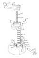
- FIG. 1is a perspective view of a manual mixer according to the present invention
- FIG. 2is a perspective assembly view of the manual mixer depicted in FIG. 1 ;
- FIG. 3is a front elevational view of the manual mixer depicted in FIG. 1 ;
- FIG. 4is a side elevational view of the manual mixer depicted in FIG. 1 ;
- FIG. 5is a top plan view of the manual mixer depicted in FIG. 1 ;
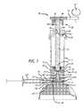
- FIG. 6is a cross-sectional view of the manual mixer of FIG. 1 showing a mixing assembly thereof in upwardly deposed position;
- FIG. 7is a cross-sectional view of the manual mixer of FIG. 1 showing the mixing assembly thereof in a downwardly deposed position.
- a manual mixer 10is provided for mixing and agitating materials for use during surgery.
- the manual mixer 10includes a pedestal portion 12 and a body portion 14 , and, as depicted in FIGS. 1-4, 6, and 7 , the body portion 14 depends upwardly from the pedestal portion 12 .
- the body portion 14as depicted in FIGS. 2, 6, and 7 is hollow and in part defines an interior 16 of the manual mixer 10 in which materials (including liquids, pastes, and/or solids) can be mixed and agitated prior to use during surgery or other medical procedure.
- materialsincluding liquids, pastes, and/or solids
- An example of a material that can be mixed using the manual mixer 10is a bone cement such as polymethyl methacrylate (PMMA).
- the body portion 14includes a top opening 18 ( FIG. 2 ), and is formed by a sidewall portion 20 and a base portion 22 ( FIGS. 6 and 7 ),
- the sidewall portion 20 and the base portion 22can be unitarily formed with the pedestal portion 12 , and along with a cap portion 24 , the sidewall portion 20 and the base portion 22 define the interior 16 of the manual mixer 10 .
- the sidewall portion 20can be substantially cylindrical, and the interior 16 can correspondingly be substantially cylindrical.
- the sidewall portion 20can include exterior markings for measuring the volume of the materials provided in the interior 16 .
- the cap portion 24can be removably attached to the sidewall portion 20 to cover the top opening 18 .
- the sidewall portion 20 and the cap portion 24can include mating threads or snap-fit mechanism facilitating their attachment to one another.
- a mixing assembly 26is provided in the interior 16 , and a crank assembly 28 is used to actuate the mixing assembly 26 .
- the mixing assembly 26(via actuation of the crank assembly 28 ) can be used in mixing and dispensing of the materials provided in the interior 16 .
- Portions of the mixing assembly 26are configured to move upwardly and downwardly within the body portion 14 .
- a valve assembly 30can be used in dispensing the materials from the manual mixer 10 .
- the crank assembly 28includes a stem portion 32 , a crank portion 34 , and a handle portion 36 , Furthermore, as depicted in FIGS, 6 and 7 , the stem portion 32 is fixedly attached to the crank portion 34 , and the handle portion 36 is rotatably attached to the crank portion 34 . Alternatively, the stem portion 32 can also be attached to the crank portion 34 and the handle portion 36 by integrally forming the crank portion 34 and/or the handle portion 36 therewith.
- the stem portion 32is cylindrical, and the stem portion 32 includes a central longitudinal axis.
- the stem portion 32can be completely or partially threaded.
- Threads 38 provided on the stern portion 32can be used in facilitating movement of the mixing assembly 26 .
- the threads 38 of the stem portion 32can be used to fixedly attach the stem portion 32 to the crank portion 34 , as well as to portions of the mixing assembly 26 .
- threads 38can be provided on or adjacent a first end portion 40 , and on or adjacent a second end portion 42 thereof.
- a threaded aperturecan be provided in the crank portion 34 to receive the threads 38 provided on the first end portion 40 of the stem portion 32 .
- a nut 44can be press fit into an aperture 46 formed in the crank portion 34 , and the threads 38 provided on the first end portion 40 can be received in the nut 44 to fixedly attach the stem portion 32 and the crank portion 34 to one another.
- the stem portion 32extends through an aperture 50 in the cap portion 24 .
- the aperture 50can be formed by a threaded cylindrical sidewall 52 for engaging the threads 38 provided on the stem portion 32 .
- the interaction between the threads 38 provided on the stem portion 32 and the threaded cylindrical sidewall 52can facilitate rotational and axial movement of the stern portion 32 within the aperture 50 .
- the stem portion 32can be rotated about its central longitudinal axis within the aperture 50 . Such rotational movement would be translated into axial movement by the interaction of the threads 38 provided on the stem portion 32 and the threaded cylindrical sidewall 52 .
- rotation of the stem portion 32serves to rotate portions of the mixing assembly 26
- the corresponding axial movement of the stem portion 32serves to move portions of the mixing assembly 26 upwardly and downwardly within the body portion 14 .
- Such rotational and axial movementserves to mix the materials provided in the interior 16 , and can also, as discussed below, be used in dispensing the materials from the manual mixer 10 .
- the pitch of the threads 38 and the threaded cylindrical sidewall 52can be altered to speed up or slow down the axial movement of the stem portion 32 .
- the stem portion 32 and the aperture 50can be non-threaded, such that the stem portion 32 can be freely rotated and moved axially (upwardly and downwardly) relative to the aperture 50 using the crank portion 34 and the handle portion 36 .
- Such rotational and axial movementcan be used in mixing materials provided in the interior 16 , and can also, as discussed below, be used in dispensing the materials from the manual mixer 10 .
- the mixing assembly 26includes a plunger 60 , a plunger adaptor 62 , and a spring 64 .
- the plunger 60serves in part as a seal for containing the materials between a lower portion 66 of the plunger 60 and the base portion 22 of the body portion 14 .
- the plunger adaptor 62engages the plunger 60 and is fixedly attached to the stem portion 32 .
- the plunger 60 and the plunger adaptor 62can be integrally formed with one another.
- a threaded aperturecan be provided in the plunger adaptor 62 to receive the threads 38 provided on the second end portion 42 of the stem portion 32 .
- a nut 70can be press fit into an aperture 72 formed in the plunger adaptor 62 , and the threads 38 formed on the second end portion 42 can be received in the nut 70 to fixedly attach the stem portion 32 and the plunger adaptor 62 to one another.
- the plunger adaptor 62is fixedly attached to the stem portion 32 , rotational and axial movement of the stem portion 32 causes the plunger 60 and the plunger adaptor 62 to rotate and move axially (i.e., upwardly and downwardly) within the body portion 14 .
- the plunger 60includes the lower portion 66 , a conical portion 74 , and various rib portions 76 .
- the conical portion 74includes an air release valve 78 allowing passage of air thereby, and the rib portions 76 facilitate engagement of the plunger 60 to the plunger adaptor 62 .
- the lower portion 66includes a first seal ring 80 , a second seal ring 82 , a connecting ring 84 , and a flange portion 86 .
- first seal ring 80 and the second seal ring 82serve as seals
- the connecting ring 84connects the first seal ring 80 and the second seal ring 82 to one another
- the flange portion 86is configured to hold a portion of the spring 64 .
- the plunger adaptor 62is substantially cylindrical.
- the plunger adaptor 62includes a top portion 90 , a sidewall portion 92 , and an inner chamber 94 formed by the sidewall portion 92 .
- the aperture 72is formed in the top portion 90 .
- the sidewall portion 92is substantially cylindrical, and includes various slits 96 for receiving the rib portions 76 .
- the inner chamber 94is sized to receive the conical portion 74 and the rib portions 76 therein.
- the plunger 60 and the plunger adaptor 62are attached to one another, when the rib portions 76 are inserted in the slits 96 , and the conical portion 74 and the rib portions 76 are received in the inner chamber 94 .
- the present inventionprovides a plunger 60 which helps move materials through the body portion 14 .
- the plungercan comprise an 0 -ring gland or other suitable means of closing off a passageway to prevent unwanted loss of cement.
- the lower portion 66 of the plunger 60serves in part as a seal for containing the materials.
- the exterior perimeters of the first seal ring 80 and the second seal ring 82contact the inner surface of the sidewall portion 20 .
- the exterior perimeters of the first seal ring 80 and the second seal ring 82can be annular to conform to the cylindrical shape of the sidewall portion 20 .
- the connecting ring 84connects and spaces apart the first seal ring 80 and the second seal ring 82 .
- the first seal ring 80 and the second seal ring 82remain in contact with the inner surface of the sidewall portion 20 as the plunger 60 moves in the body portion 14 , and such contact inhibits the passage of the materials thereby.
- the spring 64includes a first end portion 100 , a second end portion 102 , and a coil 104 extending between the first end portion 100 and the second end portion 102 .
- the lower portion 66also serves in part for securely engaging the spring 64 .
- the lower portion 66 of the plunger 60includes the flange portion 86 .
- the flange portion 86is configured to hold the first end portion 100 of the spring 64 to facilitate attachment thereof to the plunger 60 .
- the second end portion 102 of the spring 64is not attached to the body portion 14 . Instead, given the length of the coil 104 , the second end portion 102 is contacted with the inner surface of the base portion 22 .
- the second end portion 102remains in contact with the inner surface of the base portion 22 as the plunger 60 and the plunger adaptor 62 move upwardly and downwardly within the body portion 14 .
- the coil 104 of the spring 64has a variable diameter. Unlike a spring having a coil of uniform diameter, the parts of the coil 104 do not fully stack upon one another as the spring 64 is compressed. Thus, when fully compressed, the spring 64 has a lesser height than a spring having a uniform diameter. As such, the plunger 60 and plunger adaptor 62 can travel farther downwardly within the body portion 14 with use of the spring 64 that has a variable diameter, than with use of a spring that has a uniform diameter.
- the spring 64is attached to the plunger 60 .
- the spring 64is rotated and correspondingly expanded or compressed.
- the rotation and expansion/compression of the spring 64serves to mix and agitate the materials provided in the interior 16 .
- the plunger 60is moveable between an upward position ( FIG. 6 ) and a downward position ( FIG. 7 ).
- the downward axial movement of the plunger 60serves to compress the materials provided in the interior 16 .
- the compression thereofcan force the materials to exit the manual mixer 10 through the valve assembly 30 . By exiting through the valve assembly 30 , the materials can be dispensed from the manual mixer 10 .
- the valve assembly 30includes a valve body portion 110 , a handle/plug portion 112 , and a connecting portion 114 .
- the valve body portion 110includes an outlet 116 , and the valve body portion 110 receives portions of the handle/plug portion 112 .
- the handle plug/portion 112includes two handles 118 , a plug 120 , and a plug port 122 .
- the handles 118allow for ambidextrous operation of the valve assembly 30 .
- the plug 120extends through the valve body portion 110 , one of the handles 118 is integrally formed with the plug 120 , and the other of the handles is fixedly attached to the plug 120 .
- the connecting portion 114can be used to attach the valve assembly 30 to the sidewall portion 20 of the body portion 14 .
- the connecting portion 114include two arm portions 124 for engaging two tabs 126 provided on the sidewall portion 20 .
- the plug port 122can be rotated into and out of communication with the outlet 116 and an outlet port 130 formed though the body portion 14 using either of the handles 118 .
- the plug port 122When the plug port 122 is in the closed position, the materials in the interior 16 are prevented from exiting the manual mixer 10 through the outlet 116 .
- the plug port 122When the plug port 122 is in the opened position, the materials are permitted to exit the the manual mixer 10 through the outlet 116 .
- the plug port 122 in the opened positionthe materials are dispensed through the outlet 116 when the plunger 60 is moved downwardly (via actuation of the crank assembly 28 ).
- the materials to be mixed and agitated therebycan be added to the interior 16 for mixing and agitation by first removing the cap portion 24 , the mixing assembly 26 , and the crank assembly 28 from the remainder of the manual mixer 10 .
- the materials to be mixed and agitatedcan be added to the interior 16 through the top opening 18 of the body portion 14 .
- the cap portion 24 , the mixing assembly 26 , and the crank assembly 28can be replaced onto the remainder of the manual mixer 10 .
- crank assembly 28can be actuated to actuate the mixing assembly 26 .
- rotation of the crank portion 34rotates the stem portion 32
- rotation of the stem portion 32serves to rotate the plunger 60 and spring 64 , as well as serves to move the plunger 60 axially upwardly and downwardly to expand and compress the spring 64 , respectively.
- Rotation of the crank portion 34 in one directioncan thus rotate the spring 64 , and move the plunger 60 downwardly to compress the spring 64 .
- Such rotational and axial movementmixes and agitates the materials.
- a syringe 132can be attached to the valve assembly 30 can be filled as the materials are dispensed from the manual mixer 10 .
Landscapes
- Chemical Kinetics & Catalysis (AREA)
- Chemical & Material Sciences (AREA)
- Health & Medical Sciences (AREA)
- Life Sciences & Earth Sciences (AREA)
- Surgery (AREA)
- Orthopedic Medicine & Surgery (AREA)
- Animal Behavior & Ethology (AREA)
- General Health & Medical Sciences (AREA)
- Public Health (AREA)
- Veterinary Medicine (AREA)
- Engineering & Computer Science (AREA)
- Nuclear Medicine, Radiotherapy & Molecular Imaging (AREA)
- Biomedical Technology (AREA)
- Heart & Thoracic Surgery (AREA)
- Medical Informatics (AREA)
- Molecular Biology (AREA)
- Epidemiology (AREA)
- Mixers Of The Rotary Stirring Type (AREA)
- Surgical Instruments (AREA)
- Prostheses (AREA)
- Accessories For Mixers (AREA)
Abstract
Description
Claims (20)
Priority Applications (10)
| Application Number | Priority Date | Filing Date | Title |
|---|---|---|---|
| US15/009,932US9808775B2 (en) | 2016-01-29 | 2016-01-29 | Manual mixer |
| KR1020187024517AKR20180118640A (en) | 2016-01-29 | 2017-01-20 | Manual mixer |
| CA3011717ACA3011717C (en) | 2016-01-29 | 2017-01-20 | Manual mixer |
| EP17744715.8AEP3407813B1 (en) | 2016-01-29 | 2017-01-20 | Manual mixer |
| AU2017212310AAU2017212310B2 (en) | 2016-01-29 | 2017-01-20 | Manual mixer |
| CN201780008202.2ACN109152598B (en) | 2016-01-29 | 2017-01-20 | hand mixer |
| PCT/US2017/014243WO2017132054A1 (en) | 2016-01-29 | 2017-01-20 | Manual mixer |
| JP2018539128AJP6821691B2 (en) | 2016-01-29 | 2017-01-20 | Manual mixer |
| US15/723,542US10005048B2 (en) | 2016-01-29 | 2017-10-03 | Manual mixer |
| US16/014,505US10279326B2 (en) | 2016-01-29 | 2018-06-21 | Manual mixer |
Applications Claiming Priority (1)
| Application Number | Priority Date | Filing Date | Title |
|---|---|---|---|
| US15/009,932US9808775B2 (en) | 2016-01-29 | 2016-01-29 | Manual mixer |
Related Child Applications (1)
| Application Number | Title | Priority Date | Filing Date |
|---|---|---|---|
| US15/723,542ContinuationUS10005048B2 (en) | 2016-01-29 | 2017-10-03 | Manual mixer |
Publications (2)
| Publication Number | Publication Date |
|---|---|
| US20170216790A1 US20170216790A1 (en) | 2017-08-03 |
| US9808775B2true US9808775B2 (en) | 2017-11-07 |
Family
ID=59386344
Family Applications (3)
| Application Number | Title | Priority Date | Filing Date |
|---|---|---|---|
| US15/009,932Active2036-02-05US9808775B2 (en) | 2016-01-29 | 2016-01-29 | Manual mixer |
| US15/723,542ActiveUS10005048B2 (en) | 2016-01-29 | 2017-10-03 | Manual mixer |
| US16/014,505ActiveUS10279326B2 (en) | 2016-01-29 | 2018-06-21 | Manual mixer |
Family Applications After (2)
| Application Number | Title | Priority Date | Filing Date |
|---|---|---|---|
| US15/723,542ActiveUS10005048B2 (en) | 2016-01-29 | 2017-10-03 | Manual mixer |
| US16/014,505ActiveUS10279326B2 (en) | 2016-01-29 | 2018-06-21 | Manual mixer |
Country Status (8)
| Country | Link |
|---|---|
| US (3) | US9808775B2 (en) |
| EP (1) | EP3407813B1 (en) |
| JP (1) | JP6821691B2 (en) |
| KR (1) | KR20180118640A (en) |
| CN (1) | CN109152598B (en) |
| AU (1) | AU2017212310B2 (en) |
| CA (1) | CA3011717C (en) |
| WO (1) | WO2017132054A1 (en) |
Cited By (2)
| Publication number | Priority date | Publication date | Assignee | Title |
|---|---|---|---|---|
| US10005048B2 (en)* | 2016-01-29 | 2018-06-26 | Kyphon SÀRL | Manual mixer |
| US10345322B2 (en)* | 2013-10-31 | 2019-07-09 | Roche Diagnostics Operations, Inc. | Cartridge for stirring and dispensing a fluid, automatic analyzer and method of analyzing a biological sample |
Families Citing this family (9)
| Publication number | Priority date | Publication date | Assignee | Title |
|---|---|---|---|---|
| US10575887B2 (en)* | 2017-08-04 | 2020-03-03 | Medtronic Holding Company Sàrl | Dispensing system and methods of use |
| US10856923B2 (en)* | 2018-01-22 | 2020-12-08 | Warsaw Orthopedic, Inc. | Manual mixer |
| KR102375915B1 (en) | 2020-02-13 | 2022-03-16 | 한남대학교 산학협력단 | High viscosity mixer |
| WO2021212275A1 (en)* | 2020-04-20 | 2021-10-28 | Covidien Lp | Motorized mixing device for use with medical agents |
| CN112337360A (en)* | 2020-11-11 | 2021-02-09 | 上海利康精准医疗技术有限公司 | Gene detects uses reagent mixing device |
| CN114669227B (en)* | 2022-03-24 | 2023-03-31 | 奥精医疗科技股份有限公司 | Preparation method of bone cement |
| CN115844511A (en)* | 2022-12-02 | 2023-03-28 | 武汉迈瑞科技有限公司 | Bone cement stirring and injecting assembly, device and bone cement stirring and injecting method |
| CN115814656A (en)* | 2022-12-02 | 2023-03-21 | 武汉迈瑞科技有限公司 | Bone cement mixing device, equipment, system and method |
| WO2024133642A1 (en)* | 2022-12-21 | 2024-06-27 | Institut Straumann Ag | Bone adhesive applicator |
Citations (31)
| Publication number | Priority date | Publication date | Assignee | Title |
|---|---|---|---|---|
| US3623474A (en)* | 1966-07-25 | 1971-11-30 | Medrad Inc | Angiographic injection equipment |
| US3701345A (en)* | 1970-09-29 | 1972-10-31 | Medrad Inc | Angiographic injector equipment |
| US3752364A (en)* | 1970-02-09 | 1973-08-14 | Vries R De | A container for ice cream |
| US4322022A (en)* | 1980-03-19 | 1982-03-30 | Whirlco, Inc. | Quick release for helically-threaded drive unit |
| US4479781A (en)* | 1982-04-01 | 1984-10-30 | ESPE Fabrik pharmazeutischer Pr/a/ parate GmbH | Dispenser for metering dental compositions |
| US4560352A (en)* | 1982-11-04 | 1985-12-24 | Espe Fabrik Pharmazeutischer Praparate Gmbh | Dispenser for metering dental compositions |
| US4808184A (en)* | 1985-05-14 | 1989-02-28 | Laboratorium Fur Experimentelle Chirurgie Forschungsinstitut | Method and apparatus for preparing a self-curing two component powder/liquid cement |
| US5137514A (en)* | 1990-11-01 | 1992-08-11 | Accumed Systems, Inc. | Inflation syringe assembly for percutaneous transluminal angioplasty |
| US5341958A (en)* | 1992-12-24 | 1994-08-30 | Bayat John J | Power operated caulking tool |
| US5516135A (en)* | 1995-05-31 | 1996-05-14 | Mcneilus Truck And Manufacturing, Inc. | Tag axle latching mechanism |
| US5588745A (en)* | 1994-09-02 | 1996-12-31 | Howmedica | Methods and apparatus for mixing bone cement components using an evacuated mixing chamber |
| US6042262A (en)* | 1997-07-29 | 2000-03-28 | Stryker Technologies Corportion | Apparatus for storing, mixing, and dispensing two-component bone cement |
| US20020191487A1 (en)* | 2000-10-25 | 2002-12-19 | Kyphon Inc. | Systems and methods for mixing and transferring flowable materials |
| US6571992B2 (en)* | 2001-01-12 | 2003-06-03 | Dentsply Research & Development Corp. | Dispensing syringe |
| US6675992B2 (en)* | 2002-04-01 | 2004-01-13 | Axel Schumann | Grease gun for a motor drive |
| US20040174768A1 (en) | 2001-07-16 | 2004-09-09 | Coffeen Jared P. | Bone cement mixing and delivery device for injection and method thereof |
| US20040196735A1 (en)* | 2002-10-07 | 2004-10-07 | Donald Barker | Apparatus for mixing and dispensing components |
| US20050222538A1 (en)* | 2004-03-30 | 2005-10-06 | Sdgi Holdings, Inc. | Surgical system for delivery of viscous fluids |
| US7008433B2 (en)* | 2001-02-15 | 2006-03-07 | Depuy Acromed, Inc. | Vertebroplasty injection device |
| US7025226B2 (en)* | 2001-04-13 | 2006-04-11 | Nipro Diabetes Systems, Inc. | Drive system for an infusion pump |
| US20060256646A1 (en)* | 2003-06-25 | 2006-11-16 | Bidoia S.A.S. Di Gianfranco Bidoia E. C. | Mixing and distribution device for fixing paste, particularly for multicomponent bone cement |
| WO2007067352A1 (en) | 2005-12-09 | 2007-06-14 | Temple University - Of The Commonwealth System Of Higher Education | Mixer |
| US20080116224A1 (en)* | 2006-03-10 | 2008-05-22 | Krueger John A | Curable material mixing and delivery device with cartridge |
| US20090264816A1 (en)* | 2008-04-22 | 2009-10-22 | Warsaw Orthopedic, Inc. | Injectable material delivery device with an integrated mixer |
| US8132959B2 (en)* | 2007-08-31 | 2012-03-13 | Stryker Corporation | Medical cement monomer ampoule cartridge for storing the ampoule, opening the ampoule and selectively discharging the monomer from the ampoule into a mixer |
| US8356927B1 (en)* | 2011-10-13 | 2013-01-22 | Angioletto Lordi | Universal hand mixer |
| US20130135957A1 (en)* | 2011-11-25 | 2013-05-30 | Heraeus Medical Gmbh | Device for mixing bone cement and method for mixing bone cement and use of the device |
| ES2422665B1 (en) | 2012-02-10 | 2014-07-01 | Universitat Polit�Cnica De Catalunya | DOSING DEVICE FOR INJECTION OF BONE CEMENTS |
| US9163749B2 (en)* | 2013-01-10 | 2015-10-20 | Kyphon Sarl | Valve control mechanism and method |
| US9204914B2 (en)* | 2012-01-27 | 2015-12-08 | Kyphon Sarl | Cement mixer and bone filler device |
| US9480955B2 (en)* | 2013-01-07 | 2016-11-01 | Kyphon Sarl | Bone cement mixing and delivery system with reduced fume exposure |
Family Cites Families (8)
| Publication number | Priority date | Publication date | Assignee | Title |
|---|---|---|---|---|
| US2922628A (en)* | 1957-03-11 | 1960-01-26 | Emil Koe Jr | Mixing device |
| US3136532A (en)* | 1961-09-20 | 1964-06-09 | George A Rudnick | Liquid blending appliance |
| JP4159202B2 (en)* | 1998-12-21 | 2008-10-01 | 日本特殊陶業株式会社 | Calcium phosphate cement kneading apparatus and method for preparing calcium phosphate cement kneaded material |
| CN1433845A (en)* | 2002-01-22 | 2003-08-06 | 朴善祐 | Disintegrator for hand mixer |
| US7524103B2 (en)* | 2003-11-18 | 2009-04-28 | Boston Scientific Scimed, Inc. | Apparatus for mixing and dispensing a multi-component bone cement |
| JP2008529663A (en)* | 2005-02-09 | 2008-08-07 | チルドレンズ メディカル センター コーポレイション | Devices that mix and deliver fluids for tissue recovery |
| GB0703053D0 (en)* | 2007-02-16 | 2007-03-28 | Ici Plc | Apparatus for and Methods of Mixing and Dispensing Samples |
| US9808775B2 (en)* | 2016-01-29 | 2017-11-07 | Kyphon SÀRL | Manual mixer |
- 2016
- 2016-01-29USUS15/009,932patent/US9808775B2/enactiveActive
- 2017
- 2017-01-20AUAU2017212310Apatent/AU2017212310B2/ennot_activeExpired - Fee Related
- 2017-01-20KRKR1020187024517Apatent/KR20180118640A/enactivePending
- 2017-01-20CACA3011717Apatent/CA3011717C/enactiveActive
- 2017-01-20EPEP17744715.8Apatent/EP3407813B1/enactiveActive
- 2017-01-20WOPCT/US2017/014243patent/WO2017132054A1/ennot_activeCeased
- 2017-01-20JPJP2018539128Apatent/JP6821691B2/ennot_activeExpired - Fee Related
- 2017-01-20CNCN201780008202.2Apatent/CN109152598B/enactiveActive
- 2017-10-03USUS15/723,542patent/US10005048B2/enactiveActive
- 2018
- 2018-06-21USUS16/014,505patent/US10279326B2/enactiveActive
Patent Citations (33)
| Publication number | Priority date | Publication date | Assignee | Title |
|---|---|---|---|---|
| US3623474A (en)* | 1966-07-25 | 1971-11-30 | Medrad Inc | Angiographic injection equipment |
| US3752364A (en)* | 1970-02-09 | 1973-08-14 | Vries R De | A container for ice cream |
| US3701345A (en)* | 1970-09-29 | 1972-10-31 | Medrad Inc | Angiographic injector equipment |
| US4322022A (en)* | 1980-03-19 | 1982-03-30 | Whirlco, Inc. | Quick release for helically-threaded drive unit |
| US4479781A (en)* | 1982-04-01 | 1984-10-30 | ESPE Fabrik pharmazeutischer Pr/a/ parate GmbH | Dispenser for metering dental compositions |
| US4560352A (en)* | 1982-11-04 | 1985-12-24 | Espe Fabrik Pharmazeutischer Praparate Gmbh | Dispenser for metering dental compositions |
| US4808184A (en)* | 1985-05-14 | 1989-02-28 | Laboratorium Fur Experimentelle Chirurgie Forschungsinstitut | Method and apparatus for preparing a self-curing two component powder/liquid cement |
| US5137514A (en)* | 1990-11-01 | 1992-08-11 | Accumed Systems, Inc. | Inflation syringe assembly for percutaneous transluminal angioplasty |
| US5341958A (en)* | 1992-12-24 | 1994-08-30 | Bayat John J | Power operated caulking tool |
| US5588745A (en)* | 1994-09-02 | 1996-12-31 | Howmedica | Methods and apparatus for mixing bone cement components using an evacuated mixing chamber |
| US5516135A (en)* | 1995-05-31 | 1996-05-14 | Mcneilus Truck And Manufacturing, Inc. | Tag axle latching mechanism |
| US6042262A (en)* | 1997-07-29 | 2000-03-28 | Stryker Technologies Corportion | Apparatus for storing, mixing, and dispensing two-component bone cement |
| US6176607B1 (en)* | 1997-07-29 | 2001-01-23 | Stryker Technologies Corporation | Apparatus for dispensing a liquid component of a two-component bone cement and for storing, mixing, and dispensing the cement |
| US20020191487A1 (en)* | 2000-10-25 | 2002-12-19 | Kyphon Inc. | Systems and methods for mixing and transferring flowable materials |
| US6571992B2 (en)* | 2001-01-12 | 2003-06-03 | Dentsply Research & Development Corp. | Dispensing syringe |
| US7008433B2 (en)* | 2001-02-15 | 2006-03-07 | Depuy Acromed, Inc. | Vertebroplasty injection device |
| US7025226B2 (en)* | 2001-04-13 | 2006-04-11 | Nipro Diabetes Systems, Inc. | Drive system for an infusion pump |
| US20040174768A1 (en) | 2001-07-16 | 2004-09-09 | Coffeen Jared P. | Bone cement mixing and delivery device for injection and method thereof |
| US6675992B2 (en)* | 2002-04-01 | 2004-01-13 | Axel Schumann | Grease gun for a motor drive |
| US20040196735A1 (en)* | 2002-10-07 | 2004-10-07 | Donald Barker | Apparatus for mixing and dispensing components |
| US20060256646A1 (en)* | 2003-06-25 | 2006-11-16 | Bidoia S.A.S. Di Gianfranco Bidoia E. C. | Mixing and distribution device for fixing paste, particularly for multicomponent bone cement |
| US20050222538A1 (en)* | 2004-03-30 | 2005-10-06 | Sdgi Holdings, Inc. | Surgical system for delivery of viscous fluids |
| WO2007067352A1 (en) | 2005-12-09 | 2007-06-14 | Temple University - Of The Commonwealth System Of Higher Education | Mixer |
| US20080116224A1 (en)* | 2006-03-10 | 2008-05-22 | Krueger John A | Curable material mixing and delivery device with cartridge |
| US8021037B2 (en)* | 2006-03-10 | 2011-09-20 | Carefusion 2200, Inc. | Curable material mixing and delivery device with cartridge |
| US8132959B2 (en)* | 2007-08-31 | 2012-03-13 | Stryker Corporation | Medical cement monomer ampoule cartridge for storing the ampoule, opening the ampoule and selectively discharging the monomer from the ampoule into a mixer |
| US20090264816A1 (en)* | 2008-04-22 | 2009-10-22 | Warsaw Orthopedic, Inc. | Injectable material delivery device with an integrated mixer |
| US8356927B1 (en)* | 2011-10-13 | 2013-01-22 | Angioletto Lordi | Universal hand mixer |
| US20130135957A1 (en)* | 2011-11-25 | 2013-05-30 | Heraeus Medical Gmbh | Device for mixing bone cement and method for mixing bone cement and use of the device |
| US9204914B2 (en)* | 2012-01-27 | 2015-12-08 | Kyphon Sarl | Cement mixer and bone filler device |
| ES2422665B1 (en) | 2012-02-10 | 2014-07-01 | Universitat Polit�Cnica De Catalunya | DOSING DEVICE FOR INJECTION OF BONE CEMENTS |
| US9480955B2 (en)* | 2013-01-07 | 2016-11-01 | Kyphon Sarl | Bone cement mixing and delivery system with reduced fume exposure |
| US9163749B2 (en)* | 2013-01-10 | 2015-10-20 | Kyphon Sarl | Valve control mechanism and method |
Non-Patent Citations (1)
| Title |
|---|
| International Search Report and Written Opinion PCT/2017/014243 the counterpart application dated Apr. 20, 2017, 12 pages. |
Cited By (3)
| Publication number | Priority date | Publication date | Assignee | Title |
|---|---|---|---|---|
| US10345322B2 (en)* | 2013-10-31 | 2019-07-09 | Roche Diagnostics Operations, Inc. | Cartridge for stirring and dispensing a fluid, automatic analyzer and method of analyzing a biological sample |
| US10005048B2 (en)* | 2016-01-29 | 2018-06-26 | Kyphon SÀRL | Manual mixer |
| US10279326B2 (en)* | 2016-01-29 | 2019-05-07 | Medtronic Holding Company Sárl | Manual mixer |
Also Published As
| Publication number | Publication date |
|---|---|
| CA3011717C (en) | 2023-08-01 |
| US10279326B2 (en) | 2019-05-07 |
| CN109152598A (en) | 2019-01-04 |
| US10005048B2 (en) | 2018-06-26 |
| AU2017212310A1 (en) | 2018-08-09 |
| KR20180118640A (en) | 2018-10-31 |
| CN109152598B (en) | 2021-03-16 |
| EP3407813A1 (en) | 2018-12-05 |
| EP3407813B1 (en) | 2021-03-03 |
| US20170216790A1 (en) | 2017-08-03 |
| EP3407813A4 (en) | 2019-11-13 |
| WO2017132054A1 (en) | 2017-08-03 |
| JP6821691B2 (en) | 2021-01-27 |
| JP2019504682A (en) | 2019-02-21 |
| US20180296994A1 (en) | 2018-10-18 |
| AU2017212310B2 (en) | 2021-05-27 |
| US20180021744A1 (en) | 2018-01-25 |
| CA3011717A1 (en) | 2017-08-03 |
Similar Documents
| Publication | Publication Date | Title |
|---|---|---|
| US10279326B2 (en) | Manual mixer | |
| WO1999065597A1 (en) | An apparatus for mixing and dispensing ingredients | |
| US5071040A (en) | Surgical adhesives mixing and dispensing implement | |
| US12419674B2 (en) | Manual mixer | |
| US5415474A (en) | Bone cement mixing and loading apparatus | |
| EP0725674B1 (en) | Method and device for feeding components for bone cement into a mixing vessel for these | |
| DE102014109905B4 (en) | Vacuum mixing system and method for mixing polymethyl methacrylate bone cement | |
| JPH1081338A (en) | Apparatus for containing two components separately, mixing them and dispensing the resulting mixture | |
| US8029183B2 (en) | Apparatus for mixing bone cement | |
| EP1759657B1 (en) | Capsule for storage, mixing and dispensing dental materials | |
| JP2005103296A (en) | Apparatus for mixing and discharging liquid and powdery materials for medical use | |
| AU2004210409B2 (en) | Orthopaedic cement mixing device | |
| TW202108236A (en) | Preparation device | |
| US6148995A (en) | Device and method for combining at least two products | |
| US3139220A (en) | Paint dispenser | |
| US20070277901A1 (en) | ProMix catalyzed aerosol paint | |
| EP0863386A1 (en) | Container closure cap with metering appliance | |
| CH712118A1 (en) | Plastic container with a discharge opening for fluid products. |
Legal Events
| Date | Code | Title | Description |
|---|---|---|---|
| AS | Assignment | Owner name:KYPHON SARL, SWITZERLAND Free format text:ASSIGNMENT OF ASSIGNORS INTEREST;ASSIGNOR:SASAKI, NEIL S.;REEL/FRAME:037695/0662 Effective date:20160128 | |
| STCF | Information on status: patent grant | Free format text:PATENTED CASE | |
| CC | Certificate of correction | ||
| AS | Assignment | Owner name:MEDTRONIC HOLDING COMPANY SARL, SWITZERLAND Free format text:ASSIGNMENT OF ASSIGNORS INTEREST;ASSIGNOR:KYPHON SARL;REEL/FRAME:047287/0186 Effective date:20180426 | |
| MAFP | Maintenance fee payment | Free format text:PAYMENT OF MAINTENANCE FEE, 4TH YEAR, LARGE ENTITY (ORIGINAL EVENT CODE: M1551); ENTITY STATUS OF PATENT OWNER: LARGE ENTITY Year of fee payment:4 | |
| AS | Assignment | Owner name:MEDTRONIC EUROPE SARL, SWITZERLAND Free format text:MERGER;ASSIGNOR:MEDTRONIC HOLDING COMPANY SARL;REEL/FRAME:070809/0661 Effective date:20241018 Owner name:MEDTRONIC HOLDING COMPANY SARL, SWITZERLAND Free format text:ASSIGNMENT OF ASSIGNORS INTEREST;ASSIGNOR:KYPHON SARL;REEL/FRAME:070796/0359 Effective date:20180426 | |
| MAFP | Maintenance fee payment | Free format text:PAYMENT OF MAINTENANCE FEE, 8TH YEAR, LARGE ENTITY (ORIGINAL EVENT CODE: M1552); ENTITY STATUS OF PATENT OWNER: LARGE ENTITY Year of fee payment:8 |