US9808337B2 - Composite interference screws and drivers - Google Patents
Composite interference screws and driversDownload PDFInfo
- Publication number
- US9808337B2 US9808337B2US14/670,794US201514670794AUS9808337B2US 9808337 B2US9808337 B2US 9808337B2US 201514670794 AUS201514670794 AUS 201514670794AUS 9808337 B2US9808337 B2US 9808337B2
- Authority
- US
- United States
- Prior art keywords
- screw
- delivery device
- distal end
- shaft
- combination
- Prior art date
- Legal status (The legal status is an assumption and is not a legal conclusion. Google has not performed a legal analysis and makes no representation as to the accuracy of the status listed.)
- Active, expires
Links
Images


Classifications
- A—HUMAN NECESSITIES
- A61—MEDICAL OR VETERINARY SCIENCE; HYGIENE
- A61F—FILTERS IMPLANTABLE INTO BLOOD VESSELS; PROSTHESES; DEVICES PROVIDING PATENCY TO, OR PREVENTING COLLAPSING OF, TUBULAR STRUCTURES OF THE BODY, e.g. STENTS; ORTHOPAEDIC, NURSING OR CONTRACEPTIVE DEVICES; FOMENTATION; TREATMENT OR PROTECTION OF EYES OR EARS; BANDAGES, DRESSINGS OR ABSORBENT PADS; FIRST-AID KITS
- A61F2/00—Filters implantable into blood vessels; Prostheses, i.e. artificial substitutes or replacements for parts of the body; Appliances for connecting them with the body; Devices providing patency to, or preventing collapsing of, tubular structures of the body, e.g. stents
- A61F2/02—Prostheses implantable into the body
- A61F2/08—Muscles; Tendons; Ligaments
- A61F2/0811—Fixation devices for tendons or ligaments
- A—HUMAN NECESSITIES
- A61—MEDICAL OR VETERINARY SCIENCE; HYGIENE
- A61B—DIAGNOSIS; SURGERY; IDENTIFICATION
- A61B17/00—Surgical instruments, devices or methods
- A61B17/04—Surgical instruments, devices or methods for suturing wounds; Holders or packages for needles or suture materials
- A61B17/0401—Suture anchors, buttons or pledgets, i.e. means for attaching sutures to bone, cartilage or soft tissue; Instruments for applying or removing suture anchors
- A—HUMAN NECESSITIES
- A61—MEDICAL OR VETERINARY SCIENCE; HYGIENE
- A61B—DIAGNOSIS; SURGERY; IDENTIFICATION
- A61B17/00—Surgical instruments, devices or methods
- A61B17/04—Surgical instruments, devices or methods for suturing wounds; Holders or packages for needles or suture materials
- A61B17/0466—Suture bridges
- A—HUMAN NECESSITIES
- A61—MEDICAL OR VETERINARY SCIENCE; HYGIENE
- A61B—DIAGNOSIS; SURGERY; IDENTIFICATION
- A61B17/00—Surgical instruments, devices or methods
- A61B17/56—Surgical instruments or methods for treatment of bones or joints; Devices specially adapted therefor
- A61B17/58—Surgical instruments or methods for treatment of bones or joints; Devices specially adapted therefor for osteosynthesis, e.g. bone plates, screws or setting implements
- A61B17/68—Internal fixation devices, including fasteners and spinal fixators, even if a part thereof projects from the skin
- A61B17/84—Fasteners therefor or fasteners being internal fixation devices
- A61B17/86—Pins or screws or threaded wires; nuts therefor
- A61B17/864—Pins or screws or threaded wires; nuts therefor hollow, e.g. with socket or cannulated
- A—HUMAN NECESSITIES
- A61—MEDICAL OR VETERINARY SCIENCE; HYGIENE
- A61B—DIAGNOSIS; SURGERY; IDENTIFICATION
- A61B17/00—Surgical instruments, devices or methods
- A61B17/56—Surgical instruments or methods for treatment of bones or joints; Devices specially adapted therefor
- A61B17/58—Surgical instruments or methods for treatment of bones or joints; Devices specially adapted therefor for osteosynthesis, e.g. bone plates, screws or setting implements
- A61B17/68—Internal fixation devices, including fasteners and spinal fixators, even if a part thereof projects from the skin
- A61B17/84—Fasteners therefor or fasteners being internal fixation devices
- A61B17/86—Pins or screws or threaded wires; nuts therefor
- A61B17/8645—Headless screws, e.g. ligament interference screws
- A—HUMAN NECESSITIES
- A61—MEDICAL OR VETERINARY SCIENCE; HYGIENE
- A61B—DIAGNOSIS; SURGERY; IDENTIFICATION
- A61B17/00—Surgical instruments, devices or methods
- A61B17/56—Surgical instruments or methods for treatment of bones or joints; Devices specially adapted therefor
- A61B17/58—Surgical instruments or methods for treatment of bones or joints; Devices specially adapted therefor for osteosynthesis, e.g. bone plates, screws or setting implements
- A61B17/68—Internal fixation devices, including fasteners and spinal fixators, even if a part thereof projects from the skin
- A61B17/84—Fasteners therefor or fasteners being internal fixation devices
- A61B17/86—Pins or screws or threaded wires; nuts therefor
- A61B17/869—Pins or screws or threaded wires; nuts therefor characterised by an open form, e.g. wire helix
- A—HUMAN NECESSITIES
- A61—MEDICAL OR VETERINARY SCIENCE; HYGIENE
- A61B—DIAGNOSIS; SURGERY; IDENTIFICATION
- A61B17/00—Surgical instruments, devices or methods
- A61B17/56—Surgical instruments or methods for treatment of bones or joints; Devices specially adapted therefor
- A61B17/58—Surgical instruments or methods for treatment of bones or joints; Devices specially adapted therefor for osteosynthesis, e.g. bone plates, screws or setting implements
- A61B17/88—Osteosynthesis instruments; Methods or means for implanting or extracting internal or external fixation devices
- A61B17/8875—Screwdrivers, spanners or wrenches
- A61B17/8877—Screwdrivers, spanners or wrenches characterised by the cross-section of the driver bit
- A61B17/888—Screwdrivers, spanners or wrenches characterised by the cross-section of the driver bit the driver bit acting on the central region of the screw head
- A—HUMAN NECESSITIES
- A61—MEDICAL OR VETERINARY SCIENCE; HYGIENE
- A61B—DIAGNOSIS; SURGERY; IDENTIFICATION
- A61B17/00—Surgical instruments, devices or methods
- A61B17/56—Surgical instruments or methods for treatment of bones or joints; Devices specially adapted therefor
- A61B17/58—Surgical instruments or methods for treatment of bones or joints; Devices specially adapted therefor for osteosynthesis, e.g. bone plates, screws or setting implements
- A61B17/88—Osteosynthesis instruments; Methods or means for implanting or extracting internal or external fixation devices
- A61B17/8875—Screwdrivers, spanners or wrenches
- A61B17/8886—Screwdrivers, spanners or wrenches holding the screw head
- A61B17/8888—Screwdrivers, spanners or wrenches holding the screw head at its central region
- A—HUMAN NECESSITIES
- A61—MEDICAL OR VETERINARY SCIENCE; HYGIENE
- A61F—FILTERS IMPLANTABLE INTO BLOOD VESSELS; PROSTHESES; DEVICES PROVIDING PATENCY TO, OR PREVENTING COLLAPSING OF, TUBULAR STRUCTURES OF THE BODY, e.g. STENTS; ORTHOPAEDIC, NURSING OR CONTRACEPTIVE DEVICES; FOMENTATION; TREATMENT OR PROTECTION OF EYES OR EARS; BANDAGES, DRESSINGS OR ABSORBENT PADS; FIRST-AID KITS
- A61F2/00—Filters implantable into blood vessels; Prostheses, i.e. artificial substitutes or replacements for parts of the body; Appliances for connecting them with the body; Devices providing patency to, or preventing collapsing of, tubular structures of the body, e.g. stents
- A61F2/02—Prostheses implantable into the body
- A61F2/08—Muscles; Tendons; Ligaments
- A61F2/0805—Implements for inserting tendons or ligaments
- A—HUMAN NECESSITIES
- A61—MEDICAL OR VETERINARY SCIENCE; HYGIENE
- A61B—DIAGNOSIS; SURGERY; IDENTIFICATION
- A61B17/00—Surgical instruments, devices or methods
- A61B17/04—Surgical instruments, devices or methods for suturing wounds; Holders or packages for needles or suture materials
- A61B17/0401—Suture anchors, buttons or pledgets, i.e. means for attaching sutures to bone, cartilage or soft tissue; Instruments for applying or removing suture anchors
- A61B2017/0409—Instruments for applying suture anchors
- A—HUMAN NECESSITIES
- A61—MEDICAL OR VETERINARY SCIENCE; HYGIENE
- A61B—DIAGNOSIS; SURGERY; IDENTIFICATION
- A61B17/00—Surgical instruments, devices or methods
- A61B17/04—Surgical instruments, devices or methods for suturing wounds; Holders or packages for needles or suture materials
- A61B17/0401—Suture anchors, buttons or pledgets, i.e. means for attaching sutures to bone, cartilage or soft tissue; Instruments for applying or removing suture anchors
- A61B2017/044—Suture anchors, buttons or pledgets, i.e. means for attaching sutures to bone, cartilage or soft tissue; Instruments for applying or removing suture anchors with a threaded shaft, e.g. screws
- A61B2017/0441—Suture anchors, buttons or pledgets, i.e. means for attaching sutures to bone, cartilage or soft tissue; Instruments for applying or removing suture anchors with a threaded shaft, e.g. screws the shaft being a rigid coil or spiral
- A—HUMAN NECESSITIES
- A61—MEDICAL OR VETERINARY SCIENCE; HYGIENE
- A61B—DIAGNOSIS; SURGERY; IDENTIFICATION
- A61B17/00—Surgical instruments, devices or methods
- A61B17/04—Surgical instruments, devices or methods for suturing wounds; Holders or packages for needles or suture materials
- A61B17/0401—Suture anchors, buttons or pledgets, i.e. means for attaching sutures to bone, cartilage or soft tissue; Instruments for applying or removing suture anchors
- A61B2017/0446—Means for attaching and blocking the suture in the suture anchor
- A61B2017/0458—Longitudinal through hole, e.g. suture blocked by a distal suture knot
- A—HUMAN NECESSITIES
- A61—MEDICAL OR VETERINARY SCIENCE; HYGIENE
- A61B—DIAGNOSIS; SURGERY; IDENTIFICATION
- A61B90/00—Instruments, implements or accessories specially adapted for surgery or diagnosis and not covered by any of the groups A61B1/00 - A61B50/00, e.g. for luxation treatment or for protecting wound edges
- A61B90/06—Measuring instruments not otherwise provided for
- A61B2090/062—Measuring instruments not otherwise provided for penetration depth
- A—HUMAN NECESSITIES
- A61—MEDICAL OR VETERINARY SCIENCE; HYGIENE
- A61F—FILTERS IMPLANTABLE INTO BLOOD VESSELS; PROSTHESES; DEVICES PROVIDING PATENCY TO, OR PREVENTING COLLAPSING OF, TUBULAR STRUCTURES OF THE BODY, e.g. STENTS; ORTHOPAEDIC, NURSING OR CONTRACEPTIVE DEVICES; FOMENTATION; TREATMENT OR PROTECTION OF EYES OR EARS; BANDAGES, DRESSINGS OR ABSORBENT PADS; FIRST-AID KITS
- A61F2/00—Filters implantable into blood vessels; Prostheses, i.e. artificial substitutes or replacements for parts of the body; Appliances for connecting them with the body; Devices providing patency to, or preventing collapsing of, tubular structures of the body, e.g. stents
- A61F2/02—Prostheses implantable into the body
- A61F2/08—Muscles; Tendons; Ligaments
- A61F2/0811—Fixation devices for tendons or ligaments
- A61F2002/0817—Structure of the anchor
- A61F2002/0841—Longitudinal channel for insertion tool running through the whole tendon anchor, e.g. for accommodating bone drill, guidewire
- A—HUMAN NECESSITIES
- A61—MEDICAL OR VETERINARY SCIENCE; HYGIENE
- A61F—FILTERS IMPLANTABLE INTO BLOOD VESSELS; PROSTHESES; DEVICES PROVIDING PATENCY TO, OR PREVENTING COLLAPSING OF, TUBULAR STRUCTURES OF THE BODY, e.g. STENTS; ORTHOPAEDIC, NURSING OR CONTRACEPTIVE DEVICES; FOMENTATION; TREATMENT OR PROTECTION OF EYES OR EARS; BANDAGES, DRESSINGS OR ABSORBENT PADS; FIRST-AID KITS
- A61F2/00—Filters implantable into blood vessels; Prostheses, i.e. artificial substitutes or replacements for parts of the body; Appliances for connecting them with the body; Devices providing patency to, or preventing collapsing of, tubular structures of the body, e.g. stents
- A61F2/02—Prostheses implantable into the body
- A61F2/08—Muscles; Tendons; Ligaments
- A61F2/0811—Fixation devices for tendons or ligaments
- A61F2002/0847—Mode of fixation of anchor to tendon or ligament
- A61F2002/0858—Fixation of tendon or ligament between anchor and bone, e.g. interference screws, wedges
- A—HUMAN NECESSITIES
- A61—MEDICAL OR VETERINARY SCIENCE; HYGIENE
- A61F—FILTERS IMPLANTABLE INTO BLOOD VESSELS; PROSTHESES; DEVICES PROVIDING PATENCY TO, OR PREVENTING COLLAPSING OF, TUBULAR STRUCTURES OF THE BODY, e.g. STENTS; ORTHOPAEDIC, NURSING OR CONTRACEPTIVE DEVICES; FOMENTATION; TREATMENT OR PROTECTION OF EYES OR EARS; BANDAGES, DRESSINGS OR ABSORBENT PADS; FIRST-AID KITS
- A61F2/00—Filters implantable into blood vessels; Prostheses, i.e. artificial substitutes or replacements for parts of the body; Appliances for connecting them with the body; Devices providing patency to, or preventing collapsing of, tubular structures of the body, e.g. stents
- A61F2/02—Prostheses implantable into the body
- A61F2/08—Muscles; Tendons; Ligaments
- A61F2/0811—Fixation devices for tendons or ligaments
- A61F2002/0847—Mode of fixation of anchor to tendon or ligament
- A61F2002/087—Anchor integrated into tendons, e.g. bone blocks, integrated rings
- A—HUMAN NECESSITIES
- A61—MEDICAL OR VETERINARY SCIENCE; HYGIENE
- A61F—FILTERS IMPLANTABLE INTO BLOOD VESSELS; PROSTHESES; DEVICES PROVIDING PATENCY TO, OR PREVENTING COLLAPSING OF, TUBULAR STRUCTURES OF THE BODY, e.g. STENTS; ORTHOPAEDIC, NURSING OR CONTRACEPTIVE DEVICES; FOMENTATION; TREATMENT OR PROTECTION OF EYES OR EARS; BANDAGES, DRESSINGS OR ABSORBENT PADS; FIRST-AID KITS
- A61F2/00—Filters implantable into blood vessels; Prostheses, i.e. artificial substitutes or replacements for parts of the body; Appliances for connecting them with the body; Devices providing patency to, or preventing collapsing of, tubular structures of the body, e.g. stents
- A61F2/02—Prostheses implantable into the body
- A61F2/08—Muscles; Tendons; Ligaments
- A61F2/0811—Fixation devices for tendons or ligaments
- A61F2002/0876—Position of anchor in respect to the bone
- A61F2002/0888—Anchor in or on a blind hole or on the bone surface without formation of a tunnel
- A—HUMAN NECESSITIES
- A61—MEDICAL OR VETERINARY SCIENCE; HYGIENE
- A61F—FILTERS IMPLANTABLE INTO BLOOD VESSELS; PROSTHESES; DEVICES PROVIDING PATENCY TO, OR PREVENTING COLLAPSING OF, TUBULAR STRUCTURES OF THE BODY, e.g. STENTS; ORTHOPAEDIC, NURSING OR CONTRACEPTIVE DEVICES; FOMENTATION; TREATMENT OR PROTECTION OF EYES OR EARS; BANDAGES, DRESSINGS OR ABSORBENT PADS; FIRST-AID KITS
- A61F2210/00—Particular material properties of prostheses classified in groups A61F2/00 - A61F2/26 or A61F2/82 or A61F9/00 or A61F11/00 or subgroups thereof
- A61F2210/0004—Particular material properties of prostheses classified in groups A61F2/00 - A61F2/26 or A61F2/82 or A61F9/00 or A61F11/00 or subgroups thereof bioabsorbable
- A—HUMAN NECESSITIES
- A61—MEDICAL OR VETERINARY SCIENCE; HYGIENE
- A61F—FILTERS IMPLANTABLE INTO BLOOD VESSELS; PROSTHESES; DEVICES PROVIDING PATENCY TO, OR PREVENTING COLLAPSING OF, TUBULAR STRUCTURES OF THE BODY, e.g. STENTS; ORTHOPAEDIC, NURSING OR CONTRACEPTIVE DEVICES; FOMENTATION; TREATMENT OR PROTECTION OF EYES OR EARS; BANDAGES, DRESSINGS OR ABSORBENT PADS; FIRST-AID KITS
- A61F2250/00—Special features of prostheses classified in groups A61F2/00 - A61F2/26 or A61F2/82 or A61F9/00 or A61F11/00 or subgroups thereof
- A61F2250/0058—Additional features; Implant or prostheses properties not otherwise provided for
- A61F2250/0096—Markers and sensors for detecting a position or changes of a position of an implant, e.g. RF sensors, ultrasound markers
- A61F2250/0097—Visible markings, e.g. indicia
Definitions
- the present disclosurerelates to medical apparatuses and procedures in general, and more particularly to medical apparatuses and procedures for reconstructing a ligament.
- ligamentsare torn or ruptured as the result of an accident. Accordingly, various procedures have been developed to repair or replace such damaged ligaments.
- the anterior and posterior cruciate ligamentsi.e., the “ACL” and “PCL”
- ACLanterior and posterior cruciate ligaments
- PCLposterior cruciate ligaments
- the anterior cruciate ligamenti.e., the ACL
- various surgical procedureshave been developed for reconstructing the ACL so as to restore substantially normal function to the knee.
- the ACLmay be reconstructed by replacing the ruptured ACL with a graft ligament.
- bone tunnelsare generally formed in both the top of the tibia and the bottom of the femur, with one end of the graft ligament being positioned in the femoral tunnel and the other end of the grail ligament being positioned in the tibial tunnel, and with the intermediate portion of the graft ligament spanning the distance between the bottom of the femur and the top of the tibia.
- the two ends of the graft ligamentare anchored in their respective bone tunnels in various ways well known in the art so that the graft ligament extends between the bottom end of the femur and the top end of the tibia in substantially the same way, and with substantially the same function, as the original ACL.
- This graft ligamentthen cooperates with the surrounding anatomical structures so as to restore substantially normal function to the knee.
- the graft ligamentmay be a ligament or tendon which is harvested from elsewhere within the patient's body, e.g., a patella tendon with or without bone blocks attached, a semitendinosus tendon and/or a gracilis tendon.
- the end of the gall ligamentis placed in the bone tunnel, and then the graft ligament is fixed in place using a headless orthopedic screw, generally known in the art as an “interference” screw.
- a headless orthopedic screwgenerally known in the art as an “interference” screw.
- the interference screwis advanced into the bone tunnel so that the interference screw extends parallel to the bone tunnel and simultaneously engages both the graft ligament and the side wall of the bone tunnel.
- the interference screwessentially drives the graft ligament laterally, into engagement with the opposing side wall of the bone tunnel, whereby to secure the graft ligament to the host bone with a so-called “interference fit”.
- the graft ligament and the host bonegrow together at their points of contact so as to provide a strong, natural joinder between the ligament and the bone.
- Interference screwshave proven to be an effective means for securing a graft ligament in a bone tunnel.
- the interference screwitself generally takes up a substantial amount of space within the bone tunnel, which can limit the surface area contact established between the graft ligament and the side wall of the bone tunnel. This in turn limits the region of bone-to-ligament in-growth, and hence can affect the strength of the joinder.
- interference screwsfabricated from absorbable materials, so that the interference screw can eventually disappear over time and bone-to-ligament in-growth can take place about the entire perimeter of the bone tunnel.
- various absorbable interference screwshave been developed which are made from biocompatible, bioabsorbable polymers, e.g., polylactic acid (PLA), polyglycolic acid (PGA), etc. These polymers generally provide the substantial mechanical strength needed to advance the interference screw into position, and to thereafter hold the graft ligament in position while bone-to-ligament in-growth occurs, without remaining in position on a permanent basis.
- PLApolylactic acid
- PGApolyglycolic acid
- interference screws made from such biocompatible, bioabsorbable polymershave proven clinically successful.
- these absorbable interference screwsstill suffer from several disadvantages.
- clinical evidencesuggests that the quality of the bone-to-ligament in-growth is somewhat different than natural bone-to-ligament in-growth, in the sense that the aforementioned bioabsorbable polymers tend to be replaced by a fibrous mass rather than a well-ordered tissue matrix.
- Second, clinical evidencesuggests that absorption generally takes a substantial period of time, e.g., on the order of three years or so. Thus, during this absorption time, the bone-to-ligament in-growth is still significantly limited by the presence of the interference screw.
- absorbable interference screwsgenerally tend to be fairly large in order to provide them with adequate strength, e.g., it is common for an interference screw to have a diameter (i.e., an outer diameter) of 8-12 mm and a length of 20-25 mm.
- the present disclosurerelates to a delivery device and screw combination.
- the combinationincludes a delivery device comprising a handle and a shaft coupled to the handle; the shaft including a proximal end, a distal end, a non-circular cannulation, and markings along a length of the shaft; an interference screw coupled to the delivery device comprising a proximal end and a distal end, the screw including threads extending in an open helical form from the proximal end to the distal end, a suture bridge located at a distal end of the screw and housed within a slot of the delivery device shaft, and a plurality of runners extending longitudinally along an interior of the screw, the runners housed within grooves of the delivery device shaft; and a suture disposed around the suture bridge, ends of the suture extending through the cannulation of the delivery device shaft.
- FIG. 1shows a first embodiment of the delivery device of the present disclosure.
- FIG. 2shows a side view of the shaft of the delivery device of FIG. 1 .
- FIG. 2Ashows an exploded view of the distal end of the shaft of FIG. 2 .
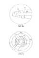
- FIG. 3shows a cross-sectional view of the shaft of FIG. 2 .
- FIG. 4shows a front view of the distal end of the shall of FIG. 2 .
- FIG. 5shows an isometric view of the screw for use with the shaft of FIG. 2 .
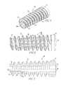
- FIG. 6shows a side view of the screw of FIG. 5 .
- FIG. 7shows a cross-sectional view of the screw of FIG. 6 .
- FIG. 8shows a second embodiment of a shaft of the present disclosure.
- FIG. 9shows a side view of the inner member of the shaft of FIG. 8 .
- FIG. 9Ashows an exploded view of the distal end of the inner member of FIG. 9 .
- FIG. 10shows a cross-sectional view of the inner member of the shall of FIG. 9 .
- FIG. 11shows a front view of the distal end of the inner member of FIG. 9 .
- FIG. 12shows an isometric view of the outer member of the shaft of FIG. 8 .
- FIG. 13shows a cross-sectional view of the outer member of FIG. 12 .
- FIGS. 14 and 15show side views of the shaft of FIG. 8 with the outer member in different positions.
- FIG. 16shows an isometric view of a third embodiment of a shaft of the present disclosure and a screw for use with the shaft.
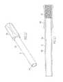
- FIG. 17shows an isometric view of the shaft of FIG. 16 .
- FIG. 18shows an isometric view of the screw of FIG. 16 .
- FIG. 19shows a side view of the screw of FIG. 16 .
- FIG. 20shows a cross-sectional view of the screw of FIG. 19 .
- FIG. 21shows an isometric view of a fourth embodiment of a shaft of the present disclosure and a screw for use with the shaft.
- FIG. 22shows an isometric view of the screw of FIG. 21 .
- FIG. 23shows an isometric view of the shaft of FIG. 21 .
- FIG. 24shows an isometric view of the shaft of FIG. 21 and an alternative screw for use with the shaft.
- FIG. 25shows a side view of the screw of FIG. 24 .
- FIG. 26shows a cross-sectional view of the screw of FIG. 24 .
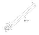
- FIG. 27shows an isometric view of a fifth embodiment of a shaft of the present disclosure and a screw for use with the shaft.
- FIG. 28shows a cross-sectional view of the shaft of FIG. 21 .
- FIG. 29shows an isometric view of a sixth embodiment of a shaft of the present disclosure and a screw for use with the shaft.
- FIG. 30shows a cross sectional view of the shaft of FIG. 29 .
- FIG. 31shows an isometric view of a seventh embodiment of a shaft of the present disclosure and a screw for use with the shaft.
- FIG. 1shows a first embodiment of the delivery device 10 of the present disclosure.
- the device 10includes a handle assembly 11 and a shaft 12 coupled to the handle assembly 11 .
- the handle assembly 11includes a handle 11 a and a connector 11 b coupled to the handle 11 a .
- the connector 11 bhas a channel 11 b ′ and an opening 11 b ′′ to the channel 11 b ′.
- the opening 11 b ′′is in the shape of a “D”.
- a proximal end 12 a of the shaft 12is disposed within the channel 11 b′.
- FIGS. 2, 2A, and 3-4show the shaft 12 .
- the shaft 12includes a proximal end 12 a and a distal end 12 b .
- the proximal end 12 ais in the shape of a “D” to match the shape of the opening 11 b ′′.
- the distal end 12 bincludes threads 12 c , grooves 12 d , and a depth stop 12 e .
- the grooves 12 dextend a partial length of the shaft 12 and intersect the threads 12 c .
- the depth stop 12 eis for use with a depth stop on a screw that the device 10 is used to implant into a bone tunnel during ligament reconstruction surgery.
- FIGS. 5-7show the screw 20 for use with the delivery device 10 of the present disclosure.
- the screw 20includes a proximal end 21 and a distal end 22 .
- a majority of the screw 20includes screw threads 23 in the form of an open helical coil, i.e. a connected series of continuous regularly spaced turns extending in a helical or spiral form substantially from the proximal end 21 to the distal end 22 with apertures 24 being defined by the space between the turns of the coil.
- interference screw 20may include an open helical coil defining an internal volume, with the internal volume communicating with the region exterior to the open helical coil through the spacing between the turns of the open helical coil.
- the distal end 22also includes a depth stop 25 that extends a partial length of the screw 20 .
- the depth stop 25includes a proximal end 25 a and a distal end 25 b . Additionally, a plurality of longitudinally-extending runners 26 extend along the interior of the screw threads 23 .
- the distal end 12 b of the shaft 12is placed within the interior of the screw 20 , via the opening 27 , until the proximal end 25 a of the depth stop 25 images the depth stop 12 e of the shaft 12 .
- the runners 26engage the grooves 12 d and become housed within the grooves 12 d .
- the distal end 12 b of the shaft 12also includes hash marks 12 f , each of which is associated with a number 12 g .
- FIGS. 8, 9-9A, and 10-15show an alternative shaft 30 of the present disclosure.
- the shaft 30includes an inner member 31 and an outer member 32 disposed over the inner member 31 .
- the proximal end 31 a of the inner member 31is similar in shape to the proximal end 12 a of the shaft 12 .
- the distal end 31 b of the inner member 31includes threads 31 c .
- Grooves 31 dextend along the member 31 and intersect the threads 31 c .
- threads 31 eare located between the proximal and distal ends 31 a , 31 b of the member 31 .
- the outer member 32includes a first section 32 a and a second section 32 b .
- the first section 32 ahas a larger diameter than the second section 32 b .
- the first section 32 aalso includes threads 32 c on an inner wall 32 d of the outer member 32 .
- the distal end 31 b of inner member 31includes hash marks numbers (not shown) that align with an end 32 b ′ of the second section 32 b , thereby indicating a length of screw 40 that will be disposed on the distal end 31 b of the inner member 31 .
- the outer member 32is located at different positions along the length of the inner member 31 to allow for screws 40 of different lengths to be loaded on the distal end 31 b of the inner member 31 .
- a handle assemblyis coupled to the proximal end 31 a of the inner member 31 .
- screw 40includes a proximal end 41 and a distal end 42 .
- the screw 40includes screw threads 43 in the form of an open helical coil having an interior and a plurality of longitudinally-extending runners 45 extending along the interior of the screw threads 43 .
- Screw 40is more fully described in United States Patent Application Publication No. 20080154314, the disclosure of which is incorporated herein by reference in its entirety.
- the screw 40is loaded onto the distal end 31 b , such that a proximal end 41 of the screw 40 engages the end 32 b ′ and the minters 45 engage the grooves 31 d and become housed within the grooves 31 d.
- FIGS. 16-20show another alternative embodiment of the shaft 50 and screw 60 of the present disclosure.
- the shaft 50includes a first portion 51 including a proximal end 51 a and a distal end 51 b and a second portion 52 including a first area 52 a and a second area 520 .
- the proximal end 51 ais configured to be coupled to a handle assembly, similar to the handle assembly 11 . However, other handle assemblies may be used.
- the first area 52 ahas a smaller diameter than the first portion 51 , such that a first depth stop 51 b ′ exists at the distal end 51 b of the first portion 51 .
- the second area 52 bhas a smaller diameter than the first area 52 a such that a second depth stop 52 c exists between the first area 52 a and the second area 52 b .
- An end 52 b ′ of the second area 52 bis tapered to allow for easier insertion of the anchor 60 into a bone during ligament reconstruction surgery, as will be further described below.
- the second portion 52also includes grooves 53 extending between the first and second areas 52 a , 52 b . For the purposes of this disclosure, there are three grooves 53 . However, the second portion 52 may include a higher or lower number of grooves 53 .
- screw 60includes a proximal end 61 and a distal end 62 .
- a majority of the screw 60includes screw threads 63 in the form of an open helical coil, i.e. a connected series of continuous regularly spaced turns extending in a helical or spiral form substantially from the proximal end 61 to the distal end 62 with apertures 64 being defined by the space between the turns of the coil.
- interference screw 60may include an open helical coil defining an internal volume, with the internal volume communicating with the region exterior to the open helical coil through the spacing between the turns of the open helical coil.
- the distal end 62also includes a depth stop 65 that extends a partial length of the screw 60 .
- the depth stop 65includes a proximal end 65 a and a distal end 65 b .
- the depth stop 65 of screw 60is a closed depth stop, most clearly shown in FIG. 18 .
- a plurality of longitudinally-extending runners 66extend along the interior of the screw threads 63 .
- the second portion 52 of the shaft 50is placed within the interior of the screw 60 , via the opening 67 , until the proximal end 65 a of the depth stop 65 engages the second depth stop 52 c of the shaft 50 .
- the runners 66engage the grooves 53 and become housed within the grooves 53 .
- the screws 60may be of a variety of lengths. For example, a screw 60 may be of such length that its proximal end 61 would engage the first depth stop 51 b′.
- the end of the gnat ligamentis placed in the bone tunnel and then the interference screw 20 , 40 , 60 is advanced into the bone tunnel via the use of shafts 12 , 30 , 50 so that the interference screw 20 , 40 , 60 extends parallel to the bone tunnel and simultaneously engages both the graft ligament and the side wall of the bone tunnel.
- the screws 20 , 40 , 60may be used in either the femoral or tibial tunnels. Methods of ligament reconstruction via use of the screws 20 , 49 , 60 is further shown in the '314 publication shown above.
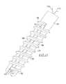
- FIGS. 21-23show yet another alternative embodiment of the screw 100 and the delivery device 200 of the present disclosure.
- the screw 100includes a proximal end 101 and a distal end 102 .
- a majority of the screw 100includes screw threads 103 in the form of an open helical coil, i.e. a connected series of continuous regularly spaced turns extending in a helical or spiral form substantially from the proximal end 101 to the distal end 102 with apertures 104 being defined by the space between the turns of the coil.
- interference screw 100may include an open helical coil dealing an internal volume, with the internal volume communicating with the region exterior to the open helical coil through the spacing between the turns of the open helical coil.
- the distal end 102also includes a suture bridge 105 that extends a partial length of the screw 100 .
- the suture bridge 105includes a proximal end 105 a and a distal end 105 b .
- the distal end 105 bincludes a concave shape.
- a flexible member 110such as a suture, is housed within the screw 100 , such that the suture 110 extends around the distal end 105 b of the bridge 105 .
- longitudinally-extending runners 106extend from the suture bridge 105 and along the interior of the screw threads 103 . For the purposes of this disclosure, there are two longitudinally extending runners 106 . However, more or less than two runners are within the scope of this disclosure.
- the delivery device 200includes a distal end 201 having a slot 202 and grooves 203 extending from the slot 202 on each side of the device 200 .
- the screw 100is located on the distal end 201 such that the suture bridge 105 is housed within the slot 202 and the runners 106 are housed within the grooves 203 .
- the delivery device 200is cannulated, such that when the screw 100 is located on the device 200 , the suture ends 110 a , 110 b extend through the cannulation 204 .
- FIGS. 24-26show a screw 300 similar to screw 100 .
- screw 300additionally includes a pointed tip 311 located on the distal end 302 .
- the tip 311includes a through hole 312 .
- the hole 312helps in locating the suture 110 within the interior of the screw 300 .
- the screw 300is located on the distal end 201 of delivery device 200 such that the suture bridge 305 is housed within the slot 202 and the runners 306 are housed within the grooves 203 .
- the delivery device 200is cumulated, such that when the screw 300 is located on the device 200 , the suture ends 110 a , 110 b extend through the cannulation 204 , as shown in FIG. 24 .
- the device 200would include a proximal end, similar to the devices above, which may be coupled to a handle assembly, similar to handle assembly 11 above.
- the screws 100 , 300are used in the repair of soft tissue, specifically to re-attach tissue to bone.
- This repairis when the screw 100 , 300 is delivered into bone via the use of device 200 , the device 200 is removed from screw 100 , 300 , the tissue is placed on the bone to be adjacent the screw 100 , 300 , the suture ends 110 a , 110 b are pulled through the tissue, and then the suture ends 110 a , 110 b are tied.
- a holemay be made in the bone prior to insertion of the screw 100 , 300 into the bone.
- screw 300may be inserted into bone without first making a hole in the bone.
- the pointed tip 311is used to start insertion of the screw 300 into the bone and then rotary motion may be used to complete insertion of the screw 300 into the bone.
- Other methods of tissue repair via use of these screws and delivery devicemay also be used.
- the distal end 201 of the delivery device 200may be shaped so as to be able to pierce bone and provide entry of the screw 100 into bone, thereby serving a purpose similar to the pointed tip 311 of screw 300 .
- the distal end 201may have an awl shape, may be pointed, or have some other shape that would allow for initiation of screw 100 insertion into the bone without having to use a separate tool.
- FIG. 27shows an alternative embodiment of the delivery device 200 and the screw 100 .
- the delivery device 400 of FIG. 27includes a distal end 401 in the form of a single pointed tip.
- the tip 401extends beyond the distal end 502 of the screw 500 .
- the screw 500is different from screw 100 in the sense that the suture bridge 505 is not centrally located on the screw 500 . Rather, the suture bridge 505 is located laterally or on a side of the screw 500 . Having the suture bridge 505 located laterally allows the delivery device 490 to maintain a solid centrally located tip 401 , rather than the split distal end 201 of delivery device 200 .
- suturewould extend around the bridge 505 and ends of the suture would extend through a cannulation of the delivery device 400 . Similar to the awl shaped distal end 201 discussed above, the distal end 401 of delivery device 400 also allows for initiation of screw 500 insertion into the bone without having to use a separate tool.
- the cannulation 204 of the delivery device 200is oval-shaped.
- FIG. 28shows a cross-sectional view of delivery device 200 , further evidencing the oval-shaped cannulation 204 .
- a non-circular shapeincluding, but not limited to, an oval shape or a rectangular shape, is used.
- FIGS. 29 and 30show an embodiment of the delivery device 200 whereby a longitudinal slot cut 205 is made completely through the device 200 . Having the slot cut 205 also serves the purpose of accommodating a full suture load inside of the cannulation 204 .
- the slot cut 205is in an elongated oval shape form for the purposes of FIG. 29 .
- the slot cut 205could be of any shape, including, without limitation, rectangular shaped.
- the delivery device 200is also tapered to be awl shaped, as described above, so as to be able to pierce bone and provide entry of the screw 700 into bone.
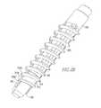
- FIG. 29also shows a screw 700 having a distal end 702 with a web 710 located between thread 703 a and thread 703 b .
- thread 703 ais the first thread to enter the bone.
- the starting point 703 a ′ of thread 703 ais engaged with the runner 706 .
- This small engagement arearequires the thread 703 a to very rapidly transition to the full threads proximal to thread 703 a , such as thread 703 b . Without a web 710 between threads 703 a and 703 b , the starting point 703 a ′ of thread 703 a may disengage from runner 706 .
- web 710provides the support needed to substantially reduce the possibility of the threads disengaging from the runners 706 , beginning with the starting point 703 a ′ of thread 703 a .
- the web 710extends between threads 703 a and 703 b and spans about 180 degrees circumferentially around the screw 700 or from one runner 706 to the other runner 706 .
- webssimilar to web 710 , to exist between the threads proximal to thread 703 b . It is also within the scope of this disclosure for web 710 to span more or less than 180 degrees circumferentially around the screw 700 . Furthermore, for the purposes of FIG. 29 , the web 710 is solid. However, it is within the scope of this disclosure that the web 710 could be non-solid, including, without limitation, a perforated web.
- FIG. 31shows a delivery device, such as delivery device 800 , including markings 806 , 807 .
- the Markings 806 , 807provide feedback to the surgeon as to the insertion progress of the screw 700 .
- the distal end 801 of the delivery device 800is tapered to be awl shaped, as described above, so as to be able to pierce bone and provide entry of the screw 700 into bone.
- Marking 806is located in-line with the starting point 703 a ′ of thread 703 a to provide visual feedback to the surgeon during insertion of the screw 700 into bone. For example, the surgeon axially inserts the distal end 801 of the device 800 into bone up to marking 806 .
- markings 807provide feedback on screw 800 insertion progress. As shown in FIG. 31 , markings 807 are numbers that create a countdown sequence. However, types of markings, other than numbers, could be used. While screw 700 is shown as being used with delivery device 800 , screw 100 could also be used with device 800 .
- the handle 11 a of handle assembly 11is made from plastic, however, other non-metal and metal materials may also be used.
- the shape and size of handle 11 amay be any shape and size necessary to help facilitate insertion of the screw 20 into bone.
- the coupler 11 bis made from a metal material, such as stainless steel or titanium, but may be made from other metal and non-metal materials that are strong enough to withstand the forces applied during surgery.
- the coupler 11 bis press-fit to the handle 11 a , but may be coupled to the handle 11 a in any other manner known to those of skill in the art.
- the size and shape of the coupler 11 bmay be any size and shape necessary to help facilitate insertion of the screw 20 into bone.
- the channel 11 b ′may be any length necessary and the opening 11 b ′′ may be any shape necessary to facilitate coupling of the shaft 12 to the coupler 11 b.
- the shaft 12is made from a metal material, such as stainless steel and titanium, however, other metal and non-metal materials that would withstand the forces applied during surgery may be used.
- the diameter of the shaft 12may vary.
- the proximal end 12 a of the shaft 12may be any shape necessary to facilitate insertion of the end 12 a through opening 11 b ′′ and into channel 11 b ′.
- the number of threads 12 e and grooves 12 dmay vary and the lengths of the grooves 12 d may also vary.
- the location of depth stop 12 cmay also vary based on the diameter of the shaft 12 and the diameter of the screw 20 that is used.
- the grooves 12 d , depth stop 12 e , and threads 12 cmay be formed by any method known to one of skill in the art.
- the screw 20is made from a polymer material via a molding method. However, other material, which would allow the screw 20 to withstand forces applied during surgery, and other methods of making may be used.
- the depth stop 25is open ended and doesn't extend the entire inner diameter of the screw 20 . The amount of screw inner diameter that the depth stop 25 covers may vary and the length of the depth stop 25 may vary based on the diameter of the screw. The number and length of the runners 26 may also vary.
- the threads 12 ccreate threads in the bone, thereby creating a seat for the screw threads 23 , as described more fully in the '314 publication.
- the amount of the distal end 12 b of the shaft 12 that extends from the distal end 22 of the screw 20may vary.
- the diameters of the first and second sections 32 a , 32 b of outer member 32may vary and the number of threads 32 c may also vary.
- the number of threads 31 c , 31 e and grooves 31 dmay vary and the lengths of the grooves 31 d may also vary.
- the inner and outer members 31 , 32are made from a metal material, such as stainless steel and titanium, and via a method known to one of skill in the art. However, other materials may also be used.
- the screw 40is made from a polymer material via a molding method. However, other material and methods of making may be used.
- the number and length of the runners 45may also vary.
- the distal end 31 b of the shaft 30extends from the distal end 42 of the screw 40 .
- the threads 31 ecreate threads in the bone, thereby creating a seat for the screw threads 43 , as described more fully in the '314 publication.
- the amount of the distal end 31 b of the shaft 30 extending from the screw 40may vary.
- the shaft 50is made from a metal material, such as stainless steel or titanium, but may be made from another metal material or a non-metal material that is strong enough to withstand the force applied to the shaft 50 during surgery.
- the shaft 50may be made via a method known to one of skill in the art.
- the diameters of the first and second portions 51 , 52may vary along with the number and lengths of the grooves 53 and the locations of the depth stops 52 c , 51 b ′ may vary based on the diameter of the screw 60 or other factors. Rather than being tapered, the end 52 b ′ may be designed in another manner to allow easier insertion of the screw 60 into bone.
- the screw 60is made from a polymer material via a molding method.
- the number and length of the runners 66may also vary. Once the screw 60 is located on the shaft 50 , the second portion 52 of the shaft 50 extends from the distal end 62 of the screw 60 . The amount of the second portion 52 extending from the screw 60 may vary. Additionally, the length of the depth stop 65 may also vary based on the diameter of the screw 60 or other factors.
- the delivery device 200is made from a metal material, such as stainless steel or titanium, but may be made from a non-metal material that is strong enough to withstand the forces applied to the device 200 during surgery.
- the delivery device 200is made via a method known to one of skill in the art.
- the screws 100 , 300are made from a polymer material and via a molding process, however, other material, which would allow the screw to withstand the forces applied during surgery, and other processes known to one of skill in the art may be used.
- the suture bridge 105may have a distal end 105 b having a shape other than concave and the length of the suture bridge 105 , the slot 202 , and the grooves 203 may vary.
- the size and the shape of the hole 312may vary.
Landscapes
- Health & Medical Sciences (AREA)
- Life Sciences & Earth Sciences (AREA)
- Orthopedic Medicine & Surgery (AREA)
- Surgery (AREA)
- Engineering & Computer Science (AREA)
- General Health & Medical Sciences (AREA)
- Biomedical Technology (AREA)
- Heart & Thoracic Surgery (AREA)
- Veterinary Medicine (AREA)
- Public Health (AREA)
- Animal Behavior & Ethology (AREA)
- Molecular Biology (AREA)
- Nuclear Medicine, Radiotherapy & Molecular Imaging (AREA)
- Medical Informatics (AREA)
- Rheumatology (AREA)
- Neurology (AREA)
- Rehabilitation Therapy (AREA)
- Cardiology (AREA)
- Oral & Maxillofacial Surgery (AREA)
- Transplantation (AREA)
- Vascular Medicine (AREA)
- Surgical Instruments (AREA)
Abstract
Description
This application is a continuation patent application of U.S. patent application Ser. No. 13/410,8223, filed Mar. 12, 2012, which is a continuation-in-part patent application claiming priority to U.S. Patent Application Ser. No. 61/451,644, filed Mar. 11, 2011, U.S. Patent Application Ser. No. 61/451,731, filed on Mar. 11, 2011, U.S. Patent Application Ser. No. 61/451,736, filed Mar. 11, 2011, U.S. Patent Application Ser. No. 61/451,743, filed on Mar. 11, 2011, and Ser. No. 13/044,777, filed on Mar. 10, 2011, which claims priority to U.S. Patent Application Ser. No. 61/312,291, filed on Mar. 10, 2010, U.S. Patent Application Ser. No. 61/334,808, filed on May 14, 2010, and U.S. Patent Application Ser. No. 61/359,080, filed on Jun. 28, 2010, the disclosures of which are incorporated herein by reference in their entireties.
Field of Technology
The present disclosure relates to medical apparatuses and procedures in general, and more particularly to medical apparatuses and procedures for reconstructing a ligament.
Related Art
In many cases, ligaments are torn or ruptured as the result of an accident. Accordingly, various procedures have been developed to repair or replace such damaged ligaments.
For example, in the human knee, the anterior and posterior cruciate ligaments (i.e., the “ACL” and “PCL”) extend between the top end of the tibia and the bottom end of the femur. Often, the anterior cruciate ligament (i.e., the ACL) is ruptured or torn as the result of, for example, a sports-related injury. Consequently, various surgical procedures have been developed for reconstructing the ACL so as to restore substantially normal function to the knee.
In many instances, the ACL may be reconstructed by replacing the ruptured ACL with a graft ligament. More particularly, in such a procedure, bone tunnels are generally formed in both the top of the tibia and the bottom of the femur, with one end of the graft ligament being positioned in the femoral tunnel and the other end of the grail ligament being positioned in the tibial tunnel, and with the intermediate portion of the graft ligament spanning the distance between the bottom of the femur and the top of the tibia. The two ends of the graft ligament are anchored in their respective bone tunnels in various ways well known in the art so that the graft ligament extends between the bottom end of the femur and the top end of the tibia in substantially the same way, and with substantially the same function, as the original ACL. This graft ligament then cooperates with the surrounding anatomical structures so as to restore substantially normal function to the knee.
In some circumstances, the graft ligament may be a ligament or tendon which is harvested from elsewhere within the patient's body, e.g., a patella tendon with or without bone blocks attached, a semitendinosus tendon and/or a gracilis tendon.
As noted above, various approaches are well known in the art for anchoring the two ends of the graft ligament in the femoral and tibial bone tunnels.
In one well-known procedure, which may be applied to femoral fixation, tibial fixation, or both, the end of the gall ligament is placed in the bone tunnel, and then the graft ligament is fixed in place using a headless orthopedic screw, generally known in the art as an “interference” screw. More particularly, with this approach, the end of the graft ligament is placed in the bone tunnel and then the interference screw is advanced into the bone tunnel so that the interference screw extends parallel to the bone tunnel and simultaneously engages both the graft ligament and the side wall of the bone tunnel. In this arrangement, the interference screw essentially drives the graft ligament laterally, into engagement with the opposing side wall of the bone tunnel, whereby to secure the graft ligament to the host bone with a so-called “interference fit”. Thereafter, over time (e.g., several months), the graft ligament and the host bone grow together at their points of contact so as to provide a strong, natural joinder between the ligament and the bone.
Interference screws have proven to be an effective means for securing a graft ligament in a bone tunnel. However, the interference screw itself generally takes up a substantial amount of space within the bone tunnel, which can limit the surface area contact established between the graft ligament and the side wall of the bone tunnel. This in turn limits the region of bone-to-ligament in-growth, and hence can affect the strength of the joinder. By way of example but not limitation, it has been estimated that the typical interference screw obstructs about 50% of the potential bone-to-ligament integration region.
For this reason, substantial efforts have been made to provide interference screws fabricated from absorbable materials, so that the interference screw can eventually disappear over time and bone-to-ligament in-growth can take place about the entire perimeter of the bone tunnel. To this end, various absorbable interference screws have been developed which are made from biocompatible, bioabsorbable polymers, e.g., polylactic acid (PLA), polyglycolic acid (PGA), etc. These polymers generally provide the substantial mechanical strength needed to advance the interference screw into position, and to thereafter hold the graft ligament in position while bone-to-ligament in-growth occurs, without remaining in position on a permanent basis.
In general, interference screws made from such biocompatible, bioabsorbable polymers have proven clinically successful. However, these absorbable interference screws still suffer from several disadvantages. First, clinical evidence suggests that the quality of the bone-to-ligament in-growth is somewhat different than natural bone-to-ligament in-growth, in the sense that the aforementioned bioabsorbable polymers tend to be replaced by a fibrous mass rather than a well-ordered tissue matrix. Second, clinical evidence suggests that absorption generally takes a substantial period of time, e.g., on the order of three years or so. Thus, during this absorption time, the bone-to-ligament in-growth is still significantly limited by the presence of the interference screw. Third, clinical evidence suggests that, for many patients, absorption is never complete, leaving a substantial foreign mass remaining within the body. This problem is exacerbated somewhat by the fact that absorbable interference screws generally tend to be fairly large in order to provide them with adequate strength, e.g., it is common for an interference screw to have a diameter (i.e., an outer diameter) of 8-12 mm and a length of 20-25 mm.
Thus, there is a need for a new and improved interference fixation system which (i) has the strength needed to hold the graft ligament in position while bone-to-ligament in-growth occurs, and OD promotes superior bone-to-ligament in-growth.
In one aspect, the present disclosure relates to a delivery device and screw combination. The combination includes a delivery device comprising a handle and a shaft coupled to the handle; the shaft including a proximal end, a distal end, a non-circular cannulation, and markings along a length of the shaft; an interference screw coupled to the delivery device comprising a proximal end and a distal end, the screw including threads extending in an open helical form from the proximal end to the distal end, a suture bridge located at a distal end of the screw and housed within a slot of the delivery device shaft, and a plurality of runners extending longitudinally along an interior of the screw, the runners housed within grooves of the delivery device shaft; and a suture disposed around the suture bridge, ends of the suture extending through the cannulation of the delivery device shaft.
Further areas of applicability of the present disclosure will become apparent from the detailed description provided hereinafter. It should be understood that the detailed description and specific examples, while indicating the preferred embodiment of the disclosure, are intended for purposes of illustration only and are not intended to limit the scope of the disclosure.
The accompanying drawings, which are incorporated in and form a part of the specification, illustrate the embodiments of the present disclosure and together with the written description serve to explain the principles, characteristics, and features of the disclosure. In the drawings:
The following description of the preferred embodiment(s) is merely exemplary in nature and is in no way intended to limit the disclosure, its application, or uses.
Thedistal end 12bof theshaft 12 is placed within the interior of thescrew 20, via theopening 27, until the proximal end25aof thedepth stop 25 images thedepth stop 12eof theshaft 12. During insertion of theshaft 12 into thescrew 20, therunners 26 engage thegrooves 12dand become housed within thegrooves 12d. As shown inFIG. 1 , thedistal end 12bof theshaft 12 also includes hash marks12f, each of which is associated with anumber 12g. Once thescrew 20 is placed on theshaft 12, theproximal end 21 of thescrew 20 aligns with one of the hash marks numbers12f, thereby indicating the length of thescrew 20.
Once theouter member 32 is disposed over theinner member 31, threads32cengagethreads 31eto move theouter member 32 relative to theinner member 31. Moving theouter member 32 relative to theinner member 31 allows for more or less of thedistal end 31bof theinner member 31 to be shown. Similar to thedistal end 12bof theshaft 12, thedistal end 31bofinner member 31 includes hash marks numbers (not shown) that align with anend 32b′ of thesecond section 32b, thereby indicating a length of screw40 that will be disposed on thedistal end 31bof theinner member 31. As shown inFIGS. 14 and 15 , theouter member 32 is located at different positions along the length of theinner member 31 to allow for screws40 of different lengths to be loaded on thedistal end 31bof theinner member 31.
A handle assembly, similar to the handle assembly11, is coupled to the proximal end31aof theinner member 31. Similar to screw20, screw40 includes a proximal end41 and adistal end 42. The screw40 includesscrew threads 43 in the form of an open helical coil having an interior and a plurality of longitudinally-extending runners45 extending along the interior of thescrew threads 43. Screw40 is more fully described in United States Patent Application Publication No. 20080154314, the disclosure of which is incorporated herein by reference in its entirety. Once theouter member 32 has been moved to indicate the screw length, the screw40 is loaded onto thedistal end 31b, such that a proximal end41 of the screw40 engages theend 32b′ and the minters45 engage thegrooves 31dand become housed within thegrooves 31d.
Similar to screw20 shown inFIGS. 5-7 , screw60 includes aproximal end 61 and adistal end 62. A majority of thescrew 60 includesscrew threads 63 in the form of an open helical coil, i.e. a connected series of continuous regularly spaced turns extending in a helical or spiral form substantially from theproximal end 61 to thedistal end 62 withapertures 64 being defined by the space between the turns of the coil. In other words,interference screw 60 may include an open helical coil defining an internal volume, with the internal volume communicating with the region exterior to the open helical coil through the spacing between the turns of the open helical coil. Thedistal end 62 also includes adepth stop 65 that extends a partial length of thescrew 60. Thedepth stop 65 includes a proximal end65aand adistal end 65b. Unlike theopen depth stop 25 ofscrew 20 most clearly shown inFIG. 5 , the depth stop65 ofscrew 60 is a closed depth stop, most clearly shown inFIG. 18 . Additionally, a plurality of longitudinally-extendingrunners 66 extend along the interior of thescrew threads 63.
Thesecond portion 52 of theshaft 50 is placed within the interior of thescrew 60, via the opening67, until the proximal end65aof thedepth stop 65 engages thesecond depth stop 52cof theshaft 50. During insertion of theshaft 50 into thescrew 60, therunners 66 engage thegrooves 53 and become housed within thegrooves 53. Thescrews 60 may be of a variety of lengths. For example, ascrew 60 may be of such length that itsproximal end 61 would engage thefirst depth stop 51b′.
As described above, during ligament reconstruction surgery, the end of the gnat ligament is placed in the bone tunnel and then theinterference screw shafts interference screw screws screws
Thedelivery device 200 includes adistal end 201 having aslot 202 andgrooves 203 extending from theslot 202 on each side of thedevice 200. As shown inFIG. 21 , thescrew 100 is located on thedistal end 201 such that thesuture bridge 105 is housed within theslot 202 and therunners 106 are housed within thegrooves 203. Thedelivery device 200 is cannulated, such that when thescrew 100 is located on thedevice 200, the suture ends110a,110bextend through thecannulation 204.
For clarity purposes, only thedistal end 201 of thedevice 200 is shown. However, thedevice 200 would include a proximal end, similar to the devices above, which may be coupled to a handle assembly, similar to handle assembly11 above. Thescrews screw device 200, thedevice 200 is removed fromscrew screw screw pointed tip 311 is used to start insertion of thescrew 300 into the bone and then rotary motion may be used to complete insertion of thescrew 300 into the bone. Other methods of tissue repair via use of these screws and delivery device may also be used.
Thedistal end 201 of thedelivery device 200 may be shaped so as to be able to pierce bone and provide entry of thescrew 100 into bone, thereby serving a purpose similar to thepointed tip 311 ofscrew 300. Thedistal end 201 may have an awl shape, may be pointed, or have some other shape that would allow for initiation ofscrew 100 insertion into the bone without having to use a separate tool.
As shown inFIG. 24 , thecannulation 204 of thedelivery device 200 is oval-shaped.FIG. 28 shows a cross-sectional view ofdelivery device 200, further evidencing the oval-shapedcannulation 204. In order to accommodate the full suture load inside of thecannulation 204, a non-circular shape, including, but not limited to, an oval shape or a rectangular shape, is used.FIGS. 29 and 30 show an embodiment of thedelivery device 200 whereby a longitudinal slot cut205 is made completely through thedevice 200. Having the slot cut205 also serves the purpose of accommodating a full suture load inside of thecannulation 204. The slot cut205 is in an elongated oval shape form for the purposes ofFIG. 29 . However, the slot cut205 could be of any shape, including, without limitation, rectangular shaped. Thedelivery device 200 is also tapered to be awl shaped, as described above, so as to be able to pierce bone and provide entry of thescrew 700 into bone.
The handle11aof handle assembly11 is made from plastic, however, other non-metal and metal materials may also be used. The shape and size of handle11amay be any shape and size necessary to help facilitate insertion of thescrew 20 into bone. The coupler11bis made from a metal material, such as stainless steel or titanium, but may be made from other metal and non-metal materials that are strong enough to withstand the forces applied during surgery. The coupler11bis press-fit to the handle11a, but may be coupled to the handle11ain any other manner known to those of skill in the art. The size and shape of the coupler11bmay be any size and shape necessary to help facilitate insertion of thescrew 20 into bone. The channel11b′ may be any length necessary and the opening11b″ may be any shape necessary to facilitate coupling of theshaft 12 to the coupler11b.
Theshaft 12 is made from a metal material, such as stainless steel and titanium, however, other metal and non-metal materials that would withstand the forces applied during surgery may be used. The diameter of theshaft 12 may vary. The proximal end12aof theshaft 12 may be any shape necessary to facilitate insertion of the end12athrough opening11b″ and into channel11b′. The number ofthreads 12eandgrooves 12dmay vary and the lengths of thegrooves 12dmay also vary. The location ofdepth stop 12cmay also vary based on the diameter of theshaft 12 and the diameter of thescrew 20 that is used. Thegrooves 12d, depth stop12e, andthreads 12cmay be formed by any method known to one of skill in the art.
Thescrew 20 is made from a polymer material via a molding method. However, other material, which would allow thescrew 20 to withstand forces applied during surgery, and other methods of making may be used. Thedepth stop 25 is open ended and doesn't extend the entire inner diameter of thescrew 20. The amount of screw inner diameter that thedepth stop 25 covers may vary and the length of thedepth stop 25 may vary based on the diameter of the screw. The number and length of therunners 26 may also vary. Once thescrew 20 is located on theshaft 12, thedistal end 12bof theshaft 12 extends from thedistal end 22 of thescrew 20. During insertion of thescrew 20 into bone, thethreads 12ccreate threads in the bone, thereby creating a seat for the screw threads23, as described more fully in the '314 publication. The amount of thedistal end 12bof theshaft 12 that extends from thedistal end 22 of thescrew 20 may vary.
The diameters of the first andsecond sections outer member 32 may vary and the number of threads32cmay also vary. The number ofthreads grooves 31dmay vary and the lengths of thegrooves 31dmay also vary. The inner andouter members distal end 31bof the shaft30 extends from thedistal end 42 of the screw40. During insertion of the screw40 into bone, thethreads 31ecreate threads in the bone, thereby creating a seat for thescrew threads 43, as described more fully in the '314 publication. The amount of thedistal end 31bof the shaft30 extending from the screw40 may vary.
Theshaft 50 is made from a metal material, such as stainless steel or titanium, but may be made from another metal material or a non-metal material that is strong enough to withstand the force applied to theshaft 50 during surgery. Theshaft 50 may be made via a method known to one of skill in the art. The diameters of the first andsecond portions grooves 53 and the locations of the depth stops52c,51b′ may vary based on the diameter of thescrew 60 or other factors. Rather than being tapered, theend 52b′ may be designed in another manner to allow easier insertion of thescrew 60 into bone. Thescrew 60 is made from a polymer material via a molding method. However, other material, which would allow the screw to withstand the forces applied during surgery, and other methods of making may be used. The number and length of therunners 66 may also vary. Once thescrew 60 is located on theshaft 50, thesecond portion 52 of theshaft 50 extends from thedistal end 62 of thescrew 60. The amount of thesecond portion 52 extending from thescrew 60 may vary. Additionally, the length of thedepth stop 65 may also vary based on the diameter of thescrew 60 or other factors.
Thedelivery device 200 is made from a metal material, such as stainless steel or titanium, but may be made from a non-metal material that is strong enough to withstand the forces applied to thedevice 200 during surgery. Thedelivery device 200 is made via a method known to one of skill in the art. Thescrews suture bridge 105 may have adistal end 105bhaving a shape other than concave and the length of thesuture bridge 105, theslot 202, and thegrooves 203 may vary. The size and the shape of thehole 312 may vary.
As various modifications could be made to the exemplary embodiments, as described above with reference to the corresponding illustrations, without departing from the scope of the disclosure, it is intended that all matter contained in the foregoing description and shown in the accompanying drawings shall be interpreted as illustrative rather than limiting. Thus, the breadth and scope of the present disclosure should not be limited by any of the above-described exemplary embodiments, but should be defined only in accordance with the following claims appended hereto and their equivalents.
Claims (16)
1. A delivery device and screw combination comprising:
a delivery device comprising a handle and a shaft coupled to the handle, the shaft including a proximal end, a distal end, and non-circular cannulation;
an interference screw coupled to the delivery device comprising a proximal end and a distal end, the screw including threads extending in an open helical form from the proximal end to the distal end, a plurality of runners extending longitudinally along an interior of the screw, the runners housed within grooves of the delivery device shaft, and a suture bridge connected to and extending transversely between distal terminuses of the plurality of runners, the suture bridge housed within a slot of the delivery device shaft; and
a suture disposed around the suture bridge with ends of the suture extending through the cannulation of the delivery device shaft.
2. The combination ofclaim 1 wherein the distal end of the delivery device shaft includes the slot and the grooves extending from the slot on either side of the delivery device shaft.
3. The combination ofclaim 1 wherein the distal end of the delivery device shaft is split into a first portion and a second portion spaced apart from the first portion by the slot of the delivery device shaft.
4. The combination ofclaim 1 wherein the distal end of the delivery device shaft terminates at a cutting edge.
5. The combination ofclaim 1 wherein the distal end of the delivery device shaft has an awl shape.
6. The combination ofclaim 1 wherein the distal end of the delivery device shaft extends beyond the distal end of the interference screw.
7. The combination ofclaim 1 wherein the non-circular cannulation is any one of an oval shape and a rectangular shape.
8. The combination ofclaim 1 wherein the plurality of runners includes two opposed runners.
9. The combination ofclaim 1 wherein the suture bridge includes a distal end with a concave shape.
10. The combination ofclaim 1 wherein the suture bridge extends a partial length of the interference screw.
11. The combination ofclaim 1 wherein the suture bridge is located to one side of the interference screw.
12. The combination ofclaim 1 further comprising a pointed tip extending, distally, from the distal terminuses of the plurality of runners; and a transverse through hole defined by the pointed tip.
13. The combination ofclaim 1 further comprising a web extending between adjacent threads at the distal end of the interference screw and spanning any one of 180 degrees, less than 180 degrees, and more than 180 degrees, circumferentially, around the interference screw.
14. The combination ofclaim 13 wherein the web is perforated.
15. The combination ofclaim 1 further comprising a web extending between adjacent threads at the distal end of the interference screw and spanning between the runners.
16. A method of attaching tissue to bone comprising:
inserting an interference screw into a bone using a delivery device and screw combination, the delivery device and screw combination comprising:
a delivery device comprising a handle and a shaft coupled to the handle, the shaft including a proximal end, a distal end, and a non-circular cannulation;
the interference screw coupled to the delivery device comprising a proximal end and a distal end, the screw including threads extending in an open helical form from the proximal end to the distal end, a plurality of runners extending longitudinally along an interior of the screw, the runners housed within grooves of the delivery device shaft, and a suture bridge connected to and extending transversely between distal terminuses of the plurality of runners, the suture bridge housed within a slot of the delivery device shaft; and
a suture disposed around the suture bridge with ends of the suture extending through the cannulation of the delivery device shaft;
removing the delivery device from the inserted interference screw;
placing tissue on the bone and adjacent to the interference screw;
pulling at least one of the suture ends through the tissue; and
tying the suture ends into a knot to attach the tissue to the bone.
Priority Applications (2)
| Application Number | Priority Date | Filing Date | Title |
|---|---|---|---|
| US14/670,794US9808337B2 (en) | 2010-03-10 | 2015-03-27 | Composite interference screws and drivers |
| US15/484,319US9949820B2 (en) | 2010-03-10 | 2017-04-11 | Composite interference screws and drivers |
Applications Claiming Priority (10)
| Application Number | Priority Date | Filing Date | Title |
|---|---|---|---|
| US31229110P | 2010-03-10 | 2010-03-10 | |
| US33480810P | 2010-05-14 | 2010-05-14 | |
| US35908010P | 2010-06-28 | 2010-06-28 | |
| US13/044,777US8979865B2 (en) | 2010-03-10 | 2011-03-10 | Composite interference screws and drivers |
| US201161451743P | 2011-03-11 | 2011-03-11 | |
| US201161451644P | 2011-03-11 | 2011-03-11 | |
| US201161451731P | 2011-03-11 | 2011-03-11 | |
| US201161451736P | 2011-03-11 | 2011-03-11 | |
| US13/418,223US9308080B2 (en) | 2010-03-10 | 2012-03-12 | Composite interference screws and drivers |
| US14/670,794US9808337B2 (en) | 2010-03-10 | 2015-03-27 | Composite interference screws and drivers |
Related Parent Applications (2)
| Application Number | Title | Priority Date | Filing Date |
|---|---|---|---|
| US13/044,777Continuation-In-PartUS8979865B2 (en) | 2010-03-10 | 2011-03-10 | Composite interference screws and drivers |
| US13/418,223ContinuationUS9308080B2 (en) | 2010-03-10 | 2012-03-12 | Composite interference screws and drivers |
Related Child Applications (1)
| Application Number | Title | Priority Date | Filing Date |
|---|---|---|---|
| US15/484,319ContinuationUS9949820B2 (en) | 2010-03-10 | 2017-04-11 | Composite interference screws and drivers |
Publications (2)
| Publication Number | Publication Date |
|---|---|
| US20150196388A1 US20150196388A1 (en) | 2015-07-16 |
| US9808337B2true US9808337B2 (en) | 2017-11-07 |
Family
ID=46455834
Family Applications (3)
| Application Number | Title | Priority Date | Filing Date |
|---|---|---|---|
| US13/418,223Active2031-12-23US9308080B2 (en) | 2010-03-10 | 2012-03-12 | Composite interference screws and drivers |
| US14/670,794Active2031-08-22US9808337B2 (en) | 2010-03-10 | 2015-03-27 | Composite interference screws and drivers |
| US15/484,319ActiveUS9949820B2 (en) | 2010-03-10 | 2017-04-11 | Composite interference screws and drivers |
Family Applications Before (1)
| Application Number | Title | Priority Date | Filing Date |
|---|---|---|---|
| US13/418,223Active2031-12-23US9308080B2 (en) | 2010-03-10 | 2012-03-12 | Composite interference screws and drivers |
Family Applications After (1)
| Application Number | Title | Priority Date | Filing Date |
|---|---|---|---|
| US15/484,319ActiveUS9949820B2 (en) | 2010-03-10 | 2017-04-11 | Composite interference screws and drivers |
Country Status (1)
| Country | Link |
|---|---|
| US (3) | US9308080B2 (en) |
Cited By (16)
| Publication number | Priority date | Publication date | Assignee | Title |
|---|---|---|---|---|
| US20180014867A1 (en)* | 2016-07-14 | 2018-01-18 | Cm Developpement | Cannulated bone screw and methods of use therefof |
| US20210290217A1 (en)* | 2020-03-17 | 2021-09-23 | Karl Storz Se & Co. Kg | Bone anchor element for inserting into a bone and/or fixing tissue to the bone, inserter, bone anchor system and method for assembling a bone anchor system |
| US11672664B2 (en) | 2012-03-09 | 2023-06-13 | Si-Bone Inc. | Systems, devices, and methods for joint fusion |
| US11678997B2 (en) | 2019-02-14 | 2023-06-20 | Si-Bone Inc. | Implants for spinal fixation and or fusion |
| US11684378B2 (en) | 2014-09-18 | 2023-06-27 | Si-Bone Inc. | Implants for bone fixation or fusion |
| US11752011B2 (en) | 2020-12-09 | 2023-09-12 | Si-Bone Inc. | Sacro-iliac joint stabilizing implants and methods of implantation |
| US11877756B2 (en) | 2017-09-26 | 2024-01-23 | Si-Bone Inc. | Systems and methods for decorticating the sacroiliac joint |
| US11980399B2 (en) | 2013-03-15 | 2024-05-14 | Si-Bone Inc. | Implants for spinal fixation or fusion |
| US12023079B2 (en) | 2012-05-04 | 2024-07-02 | Si-Bone Inc. | Fenestrated implant |
| US12083026B2 (en) | 2019-12-09 | 2024-09-10 | Si-Bone Inc. | Sacro-iliac joint stabilizing implants and methods of implantation |
| US12161374B2 (en) | 2014-09-18 | 2024-12-10 | Si-Bone Inc. | Matrix implant |
| US12201330B2 (en) | 2019-11-27 | 2025-01-21 | Si-Bone Inc. | Bone stabilizing implants and methods of placement across si joints |
| US12220326B2 (en) | 2013-10-15 | 2025-02-11 | Si-Bone Inc. | Implant placement |
| US12419668B2 (en) | 2019-11-21 | 2025-09-23 | Si-Bone Inc. | Rod coupling assemblies for bone stabilization constructs |
| US12427028B2 (en) | 2018-03-28 | 2025-09-30 | Si-Bone Inc. | Threaded implants and methods of use across bone segments |
| US12433733B2 (en) | 2023-08-15 | 2025-10-07 | Si-Bone Inc. | Pelvic stabilization implants, methods of use and manufacture |
Families Citing this family (36)
| Publication number | Priority date | Publication date | Assignee | Title |
|---|---|---|---|---|
| US8894661B2 (en) | 2007-08-16 | 2014-11-25 | Smith & Nephew, Inc. | Helicoil interference fixation system for attaching a graft ligament to a bone |
| US9579188B2 (en) | 2010-03-10 | 2017-02-28 | Smith & Nephew, Inc. | Anchor having a controlled driver orientation |
| US9775702B2 (en) | 2010-03-10 | 2017-10-03 | Smith & Nephew, Inc. | Composite interference screws and drivers |
| US9308080B2 (en) | 2010-03-10 | 2016-04-12 | Smith & Nephew Inc. | Composite interference screws and drivers |
| MX344606B (en) | 2011-03-11 | 2016-12-20 | Smith & Nephew Inc | Trephine. |
| US20140222088A1 (en)* | 2011-05-08 | 2014-08-07 | Spinal Ventures, Llc | Implant and Fastener Fixation Devices and Delivery Instrumentation |
| AU2012267924B2 (en) | 2011-06-07 | 2016-08-11 | Smith & Nephew, Inc. | Surgical anchor delivery system |
| US20130123809A1 (en) | 2011-11-11 | 2013-05-16 | VentureMD Innovations, LLC | Transosseous attachment instruments |
| US10548585B2 (en) | 2011-11-16 | 2020-02-04 | VentureMD Innovations, LLC | Soft tissue attachment |
| US10675014B2 (en) | 2011-11-16 | 2020-06-09 | Crossroads Extremity Systems, Llc | Knotless soft tissue attachment |
| US10470756B2 (en) | 2011-11-16 | 2019-11-12 | VentureMD Innovations, LLC | Suture anchor and method |
| US10136883B2 (en) | 2011-11-16 | 2018-11-27 | VentureMD Innovations, LLC | Method of anchoring a suture |
| EP2834440B1 (en)* | 2012-03-08 | 2017-05-03 | Paul Arne Nesbø | Adjustable support device for a frame member and installation method |
| US9687221B2 (en) | 2013-02-13 | 2017-06-27 | Venture MD Innovations, LLC | Method of anchoring a suture |
| KR20150128684A (en)* | 2013-03-06 | 2015-11-18 | 스미스 앤드 네퓨, 인크. | Composite interference screws and drivers |
| US9427270B2 (en)* | 2013-03-14 | 2016-08-30 | Smith & Nephew, Inc. | Reduced area thread profile for an open architecture anchor |
| US9155531B2 (en) | 2013-03-15 | 2015-10-13 | Smith & Nephew, Inc. | Miniaturized dual drive open architecture suture anchor |
| WO2014169058A1 (en) | 2013-04-09 | 2014-10-16 | Smith & Nephew, Inc | Open-architecture interference screw |
| WO2015164342A1 (en)* | 2014-04-21 | 2015-10-29 | Smith & Nephew, Inc. | Torsional insertion system |
| FR3024834B1 (en)* | 2014-08-13 | 2021-10-29 | In2Bones | CANNULA SURGICAL TOOL, SURGICAL KIT, MANUFACTURING PROCESS AND MACHINE FOR MANUFACTURING SUCH A TOOL |
| US9931141B2 (en)* | 2014-11-26 | 2018-04-03 | Ex Technology, Llc | Method and apparatus for joint fusion |
| DE102014226493B4 (en)* | 2014-12-18 | 2020-11-12 | Holger Erne | Connecting element for fixing at least two bones or bone fragments of a living being |
| US9962174B2 (en) | 2015-07-17 | 2018-05-08 | Kator, Llc | Transosseous method |
| US10258401B2 (en)* | 2015-07-17 | 2019-04-16 | Kator, Llc | Transosseous guide |
| US10820918B2 (en) | 2015-07-17 | 2020-11-03 | Crossroads Extremity Systems, Llc | Transosseous guide and method |
| US10226243B2 (en) | 2015-08-04 | 2019-03-12 | Kator, Llc | Transosseous suture anchor |
| US12383253B2 (en) | 2015-08-04 | 2025-08-12 | Crossroads Extremity Systems, Llc | Suture anchor |
| EP3319553B1 (en) | 2015-08-14 | 2024-01-31 | Willis, Timothy R. | Intraocular lenses (iols) and related assemblies |
| US10166116B2 (en)* | 2015-12-02 | 2019-01-01 | Brian Patrick Janowski | Helical lock spacer, instruments and methods |
| CN105769269A (en)* | 2016-02-22 | 2016-07-20 | 运怡(北京)医疗器械有限公司 | Hollow interface nail |
| US11376050B2 (en) | 2017-06-27 | 2022-07-05 | Medos International Sarl | Bone screw |
| US10772667B2 (en)* | 2017-12-22 | 2020-09-15 | Medos International Sarl | Bone screw with cutting tip |
| DE102019104545A1 (en)* | 2019-02-22 | 2020-08-27 | Biotrics Biomaterials GmbH | Cortical screw made of bioresorbable material |
| AU2021201202A1 (en)* | 2020-03-23 | 2021-10-07 | Smith & Nephew Asia Pacific Pte. Limited | Anchor delivery systems |
| US12349894B2 (en) | 2020-05-06 | 2025-07-08 | Smith & Nephew, Inc. | Suture anchor insertion assemblies and methods of use |
| EP4231926A1 (en)* | 2020-10-26 | 2023-08-30 | Smith & Nephew, Inc. | Tissue repair systems and methods of assembly |
Citations (259)
| Publication number | Priority date | Publication date | Assignee | Title |
|---|---|---|---|---|
| US2288864A (en) | 1940-12-03 | 1942-07-07 | Whitehead Walter John | Means for holding parts together |
| US3320783A (en) | 1966-12-09 | 1967-05-23 | Chicago Lock Co | Key for an axial tumbler type lock |
| US3499222A (en) | 1965-08-17 | 1970-03-10 | Leonard I Linkow | Intra-osseous pins and posts and their use and techniques thereof |
| US3716058A (en) | 1970-07-17 | 1973-02-13 | Atlanta Res Inst | Barbed suture |
| US3821975A (en) | 1972-11-16 | 1974-07-02 | L Haker | Automotive wheel lock means |
| US3869942A (en) | 1974-02-04 | 1975-03-11 | Textron Inc | Driving tool |
| US3874258A (en) | 1973-05-21 | 1975-04-01 | Stallion Enterprises Inc | Keyed attachment device for vehicle wheels |
| US4027572A (en) | 1974-05-13 | 1977-06-07 | Burge William G | Theft-prevention screw fastenings |
| US4177797A (en) | 1977-03-04 | 1979-12-11 | Shelby M. Baylis | Rotary biopsy device and method of using same |
| USD288777S (en) | 1983-11-22 | 1987-03-17 | Kwon Kee J | Vehicle wheel locking nut |
| US4653489A (en) | 1984-04-02 | 1987-03-31 | Tronzo Raymond G | Fenestrated hip screw and method of augmented fixation |
| US4738255A (en) | 1986-04-07 | 1988-04-19 | Biotron Labs, Inc. | Suture anchor system |
| US4741651A (en) | 1986-04-25 | 1988-05-03 | Despres Roger J | Hole saw |
| US4834757A (en) | 1987-01-22 | 1989-05-30 | Brantigan John W | Prosthetic implant |
| US4854311A (en) | 1986-01-09 | 1989-08-08 | Acro Med Corporation | Bone screw |
| USRE33114E (en) | 1983-03-17 | 1989-11-21 | Tamper-proof threaded fastenings | |
| US4913143A (en) | 1986-05-28 | 1990-04-03 | The United States Of America As Represented By The Secretary Of The Air Force | Trephine assembly |
| US4961740A (en) | 1988-10-17 | 1990-10-09 | Surgical Dynamics, Inc. | V-thread fusion cage and method of fusing a bone joint |
| US4988351A (en) | 1989-01-06 | 1991-01-29 | Concept, Inc. | Washer for use with cancellous screw for attaching soft tissue to bone |
| US5055104A (en) | 1989-11-06 | 1991-10-08 | Surgical Dynamics, Inc. | Surgically implanting threaded fusion cages between adjacent low-back vertebrae by an anterior approach |
| US5094133A (en) | 1989-06-03 | 1992-03-10 | C. & E. Fein Gmbh & Co. | Screwdriver with switch-off means for screw-in depth and screw-in torque |
| US5116337A (en) | 1991-06-27 | 1992-05-26 | Johnson Lanny L | Fixation screw and method for ligament reconstruction |
| US5129904A (en) | 1986-08-05 | 1992-07-14 | Illi Oscar E | Osteosynthetic implant |
| US5129906A (en) | 1989-09-08 | 1992-07-14 | Linvatec Corporation | Bioabsorbable tack for joining bodily tissue and in vivo method and apparatus for deploying same |
| US5139520A (en) | 1990-01-31 | 1992-08-18 | American Cyanamid Company | Method for acl reconstruction |
| US5197967A (en) | 1991-04-02 | 1993-03-30 | Synthes (U.S.A.) | Trephine instrument and method for cutting annular holes |
| EP0538895A2 (en) | 1991-10-25 | 1993-04-28 | Peter Dr. Habermeyer | Cement-free endosprosthesis |
| US5236431A (en) | 1991-07-22 | 1993-08-17 | Synthes | Resorbable fixation device with controlled stiffness for treating bodily material in vivo and introducer therefor |
| US5242447A (en) | 1992-02-06 | 1993-09-07 | Howmedica Inc. | Pin with tapered root diameter |
| US5354299A (en) | 1992-12-07 | 1994-10-11 | Linvatec Corporation | Method of revising a screw in a tunnel |
| US5364400A (en) | 1992-02-14 | 1994-11-15 | American Cyanamid Co. | Interference implant |
| US5370662A (en) | 1993-06-23 | 1994-12-06 | Kevin R. Stone | Suture anchor assembly |
| US5383878A (en) | 1990-09-04 | 1995-01-24 | Hip Developments Pty Ltd. | Surgical screw |
| US5407427A (en) | 1992-06-16 | 1995-04-18 | Loma Linda University Medical Center | Trocar facilitator for endoscopic surgery |
| US5411506A (en) | 1994-04-11 | 1995-05-02 | Mitek Surgical Products, Inc. | Anchor driver |
| US5411523A (en) | 1994-04-11 | 1995-05-02 | Mitek Surgical Products, Inc. | Suture anchor and driver combination |
| US5423823A (en) | 1993-02-18 | 1995-06-13 | Arthrex Inc. | Coring reamer |
| US5431660A (en) | 1993-11-30 | 1995-07-11 | Burke; Dennis W. | Spring loaded screw and driver/extractor therefor |
| US5447533A (en) | 1992-09-03 | 1995-09-05 | Pacesetter, Inc. | Implantable stimulation lead having an advanceable therapeutic drug delivery system |
| US5464427A (en) | 1994-10-04 | 1995-11-07 | Synthes (U.S.A.) | Expanding suture anchor |
| US5470334A (en) | 1991-03-05 | 1995-11-28 | Linvatec Corporation | Bioabsorbable interference bone fixation screw |
| EP0686373A1 (en) | 1994-06-09 | 1995-12-13 | Bristol-Myers Squibb Company | Suture anchor |
| WO1996008205A1 (en) | 1994-09-15 | 1996-03-21 | Surgical Dynamics, Inc. | Conically-shaped anterior fusion cage and method of implantation |
| GB2294399A (en) | 1994-10-28 | 1996-05-01 | Jbs Sa | Hollow bone-screw and sealing member for stabilising vertebrae |
| WO1996019947A1 (en) | 1994-12-23 | 1996-07-04 | Institut Straumann Ag | Hollow-body dental implant with bone integration holes in its anchorage section |
| US5571139A (en) | 1995-05-19 | 1996-11-05 | Jenkins, Jr.; Joseph R. | Bidirectional suture anchor |
| US5593409A (en) | 1988-06-13 | 1997-01-14 | Sofamor Danek Group, Inc. | Interbody spinal fusion implants |
| US5609636A (en) | 1994-05-23 | 1997-03-11 | Spine-Tech, Inc. | Spinal implant |
| US5609635A (en) | 1988-06-28 | 1997-03-11 | Michelson; Gary K. | Lordotic interbody spinal fusion implants |
| US5626613A (en) | 1995-05-04 | 1997-05-06 | Arthrex, Inc. | Corkscrew suture anchor and driver |
| US5632747A (en) | 1995-03-15 | 1997-05-27 | Osteotech, Inc. | Bone dowel cutter |
| US5676545A (en) | 1994-08-15 | 1997-10-14 | Jones; Shedrick D. | Method and apparatus for implantation |
| US5681352A (en) | 1996-03-06 | 1997-10-28 | Kinetikos Medical Incorporated | Method and apparatus for anchoring surgical ties to bone |
| US5688285A (en) | 1995-08-29 | 1997-11-18 | Yamada; Ikufumi | Graft bone fixation tool |
| US5690676A (en) | 1990-07-13 | 1997-11-25 | Smith & Nephew, Inc. | Suture anchor and drive assembly |
| US5695497A (en) | 1994-03-29 | 1997-12-09 | Stahelin; Andreas C. | Screw made of biodegradable material for bone surgery purposes, and screwdriver suitable therefor |
| US5702397A (en) | 1996-02-20 | 1997-12-30 | Medicinelodge, Inc. | Ligament bone anchor and method for its use |
| JPH10200A (en) | 1996-03-14 | 1998-01-06 | Surgical Dynamics Inc | Method and equipment for inserting transplanting body |
| US5709683A (en) | 1995-12-19 | 1998-01-20 | Spine-Tech, Inc. | Interbody bone implant having conjoining stabilization features for bony fusion |
| WO1998002117A1 (en) | 1996-07-15 | 1998-01-22 | Aesculap Ag & Co. Kg | Implant for vertebral body fusion |
| WO1998026717A1 (en) | 1996-12-19 | 1998-06-25 | Bionx Implants Oy | Suture anchor |
| EP0682917B1 (en) | 1994-04-22 | 1998-08-12 | Institut Straumann Ag | Screwdriver for a screw consisting of a bolt and a nut adapted to be screwed thereon |
| US5802794A (en) | 1997-05-05 | 1998-09-08 | Jayne Industries Inc. | Ceramic fiber securing device |
| FR2760355A1 (en) | 1997-03-07 | 1998-09-11 | Serge Schrayer | Intersomatic cage, e.g. for fusion of vertebrae or joint bones |
| US5876405A (en) | 1997-09-17 | 1999-03-02 | The Anspach Effort, Inc. | Perforator |
| US5888227A (en) | 1995-10-20 | 1999-03-30 | Synthes (U.S.A.) | Inter-vertebral implant |
| US5891146A (en) | 1997-10-15 | 1999-04-06 | Applied Biological Concepts, Inc. | Wedge orthopedic screw |
| US5921982A (en) | 1993-07-30 | 1999-07-13 | Lesh; Michael D. | Systems and methods for ablating body tissue |
| US5961524A (en) | 1998-03-11 | 1999-10-05 | Stryker Technologies Corporation | Screw and method of attachment to a substrate |
| US5964783A (en) | 1997-11-07 | 1999-10-12 | Arthrex, Inc. | Suture anchor with insert-molded suture |
| US5968098A (en) | 1996-10-22 | 1999-10-19 | Surgical Dynamics, Inc. | Apparatus for fusing adjacent bone structures |
| US5968047A (en) | 1996-04-05 | 1999-10-19 | Reed; Thomas Mills | Fixation devices |
| US5984967A (en) | 1995-03-27 | 1999-11-16 | Sdgi Holdings, Inc. | Osteogenic fusion devices |
| US6008433A (en) | 1998-04-23 | 1999-12-28 | Stone; Kevin R. | Osteotomy wedge device, kit and methods for realignment of a varus angulated knee |
| US6039762A (en) | 1995-06-07 | 2000-03-21 | Sdgi Holdings, Inc. | Reinforced bone graft substitutes |
| EP0669110B1 (en) | 1994-02-14 | 2000-05-03 | Smith & Nephew, Inc. | Interference screw having a double tapered root |
| US6086593A (en) | 1998-06-30 | 2000-07-11 | Bonutti; Peter M. | Method and apparatus for use in operating on a bone |
| US6096060A (en) | 1999-05-20 | 2000-08-01 | Linvatec Corporation | Bioabsorbable threaded soft tissue anchor system |
| US6097986A (en) | 1997-12-17 | 2000-08-01 | Cardiac Pacemakers, Inc. | Retractable lead with mesh screen |
| US6132435A (en) | 1999-09-14 | 2000-10-17 | Synthes (Usa) | Torque limiting device for surgical use |
| US6196780B1 (en) | 1998-01-26 | 2001-03-06 | Wakai & Co., Ltd. | Threaded anchor |
| US6214031B1 (en) | 1996-08-05 | 2001-04-10 | Arthrex, Inc. | Corkscrew suture anchor |
| US6235057B1 (en) | 1995-01-24 | 2001-05-22 | Smith & Nephew, Inc. | Method for soft tissue reconstruction |
| FR2803739A1 (en) | 2000-01-13 | 2001-07-20 | Denis Bertin | Threaded medical implant of relatively weak material e.g. for fixing ligament has lengthwise cavity with two inner projections for tool |
| US6283973B1 (en) | 1998-12-30 | 2001-09-04 | Depuy Orthopaedics, Inc. | Strength fixation device |
| US6302632B1 (en) | 1998-11-17 | 2001-10-16 | Chao-Wei Lin | Screw with compound recesses |
| US20020022862A1 (en) | 1996-08-05 | 2002-02-21 | Arthrex, Inc. | Hex drive bioabsorbable tissue anchor |
| US6360129B1 (en) | 1999-12-13 | 2002-03-19 | Cardiac Pacemakers, Inc. | Mannitol/hydrogel cap for tissue-insertable connections |
| US20020052629A1 (en) | 2000-09-12 | 2002-05-02 | Morgan Daniel E. | Apparatus and method for securing suture to bone |
| US20020055737A1 (en) | 2000-11-08 | 2002-05-09 | The Cleveland Clinic Foundation | Apparatus for implantation into bone related applications |
| US20020055742A1 (en) | 2000-11-08 | 2002-05-09 | The Cleveland Clinic Foundation | Apparatus for attaching fractured sections of bone |
| US20020055738A1 (en) | 2000-11-08 | 2002-05-09 | The Cleveland Clinic Foundation | Apparatus for implantation into bone |
| EP1093774B1 (en) | 1999-10-21 | 2002-06-19 | Karl Storz GmbH & Co. KG | Interference screw |
| US20020087190A1 (en) | 1999-02-02 | 2002-07-04 | Benavitz William C. | Insert molded push-in suture anchor |
| US20020087189A1 (en) | 1993-02-04 | 2002-07-04 | Bonutti Peter M. | Method and apparatus for positioning a suture anchor |
| US20020099382A1 (en) | 2001-01-25 | 2002-07-25 | Salazar Bartolome J. | Guide bushing for coring reamer, storage package for reamer assembly, and method of use |
| US20020111653A1 (en) | 2001-02-12 | 2002-08-15 | Opus Medical, Inc. | Method and apparatus for attaching connective tissues to bone using a knotless suture anchoring device |
| EP1234637A2 (en) | 2001-02-26 | 2002-08-28 | Arthrex Inc | Torque driver for interference screw |
| US6443989B1 (en) | 2000-12-04 | 2002-09-03 | Roger P. Jackson | Posterior expandable fusion cage |
| US6447545B1 (en) | 2000-07-01 | 2002-09-10 | George W. Bagby | Self-aligning bone implant |
| US20020143335A1 (en) | 2001-03-30 | 2002-10-03 | Von Hoffmann Gerard | Distal bone anchors for bone fixation with secondary compression |
| US20020165546A1 (en) | 2001-04-18 | 2002-11-07 | Goble E. Marlowe | Apparatus and method for attaching a graft ligament to a bone |
| US6488683B2 (en) | 2000-11-08 | 2002-12-03 | Cleveland Clinic Foundation | Method and apparatus for correcting spinal deformity |
| US6503251B1 (en) | 2000-10-23 | 2003-01-07 | John H. Shadduck | Offset helix surgical fixation screws and methods of use |
| US6514257B2 (en) | 2001-05-02 | 2003-02-04 | Citieffe S.R.L. | Device for anchoring an elongated tensile flexible element for reconstruction of a torn ligament |
| US6517542B1 (en) | 1999-08-04 | 2003-02-11 | The Cleveland Clinic Foundation | Bone anchoring system |
| US20030055431A1 (en) | 2001-09-19 | 2003-03-20 | James Kevin Brannon | Bone cutting assembly |
| US20030065374A1 (en) | 2001-10-01 | 2003-04-03 | Medtronic, Inc. | Active fixation lead with helix extension indicator |
| US20030065361A1 (en) | 2001-10-02 | 2003-04-03 | Dreyfuss Peter J. | Suture anchor with internal suture loop |
| US20030069640A1 (en) | 2001-08-20 | 2003-04-10 | Ferreira Rui J. | Allograft spinal implant |
| US6551322B1 (en) | 2000-10-05 | 2003-04-22 | The Cleveland Clinic Foundation | Apparatus for implantation into bone |
| US6551320B2 (en) | 2000-11-08 | 2003-04-22 | The Cleveland Clinic Foundation | Method and apparatus for correcting spinal deformity |
| US6554830B1 (en) | 2000-04-10 | 2003-04-29 | Sdgi Holdings, Inc. | Fenestrated surgical anchor and method |
| US20030125749A1 (en) | 2001-12-27 | 2003-07-03 | Ethicon, Inc. | Cannulated screw and associated driver system |
| WO2003063713A1 (en) | 2002-01-25 | 2003-08-07 | Stryker Endoscopy | Threaded suture anchor and method of use |
| US6604945B1 (en) | 1994-08-15 | 2003-08-12 | Shedrick D. Jones | Method and apparatus for implantation |
| US20030181913A1 (en) | 2000-10-05 | 2003-09-25 | The Cleveland Clinic Foundation | Apparatus for implantation into bone |
| US6626971B1 (en) | 1998-09-15 | 2003-09-30 | Siemens Axiva Gmbh & Co. Kg | Method and device for protecting persons and/or products from air-borne particles |
| US6626917B1 (en) | 1999-10-26 | 2003-09-30 | H. Randall Craig | Helical suture instrument |
| US20030195529A1 (en) | 2002-04-15 | 2003-10-16 | Shinichi Takamoto | Intracardiac suture device |
| US6648903B1 (en) | 1998-09-08 | 2003-11-18 | Pierson, Iii Raymond H. | Medical tensioning system |
| US6656183B2 (en) | 2001-11-08 | 2003-12-02 | Smith & Nephew, Inc. | Tissue repair system |
| WO2003103507A2 (en) | 2002-06-11 | 2003-12-18 | Tyco Healthcare Group, Lp | Hernia mesh tacks |
| US6666888B1 (en) | 2000-08-23 | 2003-12-23 | Roger P. Jackson | Threaded fusion cage with enhanced anterior support |
| US20040015170A1 (en) | 2000-05-01 | 2004-01-22 | Tallarida Steven J. | System and method for joint resurface repair |
| US20040030343A1 (en) | 2000-11-23 | 2004-02-12 | Michel Kurc | Drilling device comprising a bone recuperating trephine |
| US20040039404A1 (en) | 2002-08-26 | 2004-02-26 | Dreyfuss Peter J. | Suture anchor attached to tissue-fixation disk without top knot |
| US20040073216A1 (en) | 2000-10-05 | 2004-04-15 | The Cleveland Clinic Foundation | Apparatus and method for attaching adjacent bones |
| FR2846867A1 (en) | 2002-11-08 | 2004-05-14 | Textile Hi Tec | Suture anchor to be inserted in bone cavity comprises long body with rounded point at distal part, interior cavity open at proximal end for insertion of tool head and longitudinal slots delimiting lateral branches comprising fins |
| US20040097945A1 (en) | 1999-11-15 | 2004-05-20 | Wolf Eugene M. | Tapered bioabsorbable interference screw for endosteal fixation of ligaments |
| EP1430843A2 (en) | 1996-08-26 | 2004-06-23 | Shedrick D. Jones | Drill apparatus for embedding an implant in bone |
| US20040122424A1 (en) | 2000-01-15 | 2004-06-24 | Ferree Bret A. | Enhanced surface area spinal fusion devices and alignment apparatus therefor |
| US20040143237A1 (en) | 2003-01-17 | 2004-07-22 | Hart Charles C. | Surgical access apparatus and method |
| US20040143158A1 (en) | 2003-01-17 | 2004-07-22 | Hart Charles C. | Surgical access apparatus and method |
| US20040153074A1 (en) | 2003-02-05 | 2004-08-05 | Bojarski Raymond A. | Tissue anchor and insertion tool |
| US6823871B2 (en) | 2000-06-01 | 2004-11-30 | Arthrex, Inc. | Allograft bone or synthetic wedges for osteotomy |
| US20040267265A1 (en) | 2003-04-29 | 2004-12-30 | Kyle Richard F. | Bone screw with fluid delivery structure |
| US6855168B2 (en) | 1997-04-25 | 2005-02-15 | Stryker France | Intersomatic implants in two parts |
| US6857343B1 (en) | 2003-09-30 | 2005-02-22 | Codman & Shurtleff, Inc. | Spring-loaded threaded fastener holder |
| US6863671B1 (en) | 1999-10-21 | 2005-03-08 | Storz Gmbh & Co. Kg | Biodegradable fixation element |
| US20050107828A1 (en) | 2003-11-14 | 2005-05-19 | Reese Karl S. | Suture loop anchor |
| US20050159727A1 (en) | 1993-07-30 | 2005-07-21 | Lesh Michael D. | Catheter system for delivery of therapeutic compounds to cardiac tissue |
| US20050222681A1 (en) | 2002-06-17 | 2005-10-06 | Richard Richley | Devices and methods for minimally invasive treatment of degenerated spinal discs |
| CN2732211Y (en) | 2004-07-10 | 2005-10-12 | 胡立人 | Interspinal grafting bone fusion device |
| US20050234458A1 (en) | 2004-04-19 | 2005-10-20 | Huebner Randall J | Expanded stabilization of bones |
| US20050250987A1 (en) | 2004-05-07 | 2005-11-10 | Usgi Medical Inc. | Removable apparatus and methods for manipulating and securing tissue |
| US20050250984A1 (en) | 2004-05-07 | 2005-11-10 | Usgi Medical Inc. | Multiple removable apparatus and methods for manipulating and securing tissue |
| US20050250988A1 (en) | 2004-05-07 | 2005-11-10 | Usgi Medical Inc. | Removable apparatus for manipulating and securing tissue within a treatment space |
| CN1701772A (en) | 1995-03-27 | 2005-11-30 | Sdgi集团有限公司 | Methods and instruments for interbody fusion |
| US20050267478A1 (en) | 2003-06-13 | 2005-12-01 | Corradi Ralph R | Surgical fastener with predetermined resorption rate |
| US20060030948A1 (en) | 2000-07-19 | 2006-02-09 | Albert Manrique | Osteoimplant and method of making same |
| US20060079895A1 (en) | 2004-09-30 | 2006-04-13 | Mcleer Thomas J | Methods and devices for improved bonding of devices to bone |
| US20060079903A1 (en) | 2004-10-08 | 2006-04-13 | Wong David A | Minimally invasive pedicle screw and guide support |
| US7033372B1 (en) | 1999-08-04 | 2006-04-25 | Percardia, Inc. | Corkscrew reinforced left ventricle to coronary artery channel |
| US20060089651A1 (en) | 2004-10-26 | 2006-04-27 | Trudeau Jeffrey L | Apparatus and method for anchoring a surgical rod |
| US20060100627A1 (en) | 2004-11-09 | 2006-05-11 | Arthrotek, Inc. | Tissue fixation device |
| US20060106390A1 (en) | 2004-11-18 | 2006-05-18 | Jensen David G | Composite bone fasteners |
| WO2006055516A2 (en) | 2004-11-15 | 2006-05-26 | Scandius Biomedical, Inc. | Method and apparatus for the repair of a rotator cuff (rtc) tendon or ligament |
| US20060142769A1 (en) | 2002-11-21 | 2006-06-29 | Michel Collette | Anchoring screw for a relay strip or suture |
| FR2879915A1 (en) | 2004-12-24 | 2006-06-30 | Advanced Biomaterials Soc Par | Interference screw for fixing ligament, has inner channel with grooves and flutes which are oriented longitudinally and distributed uniformly along surface of inner channel which extends through another channel emerging at level of point |
| US20060149266A1 (en) | 2004-12-10 | 2006-07-06 | New York Society For The Ruptured And Crippled Maintaining The Hospital For Special Surgery | Anchor for screw fixation of soft tissue to bone |
| US7083647B1 (en) | 1996-11-27 | 2006-08-01 | Sklar Joseph H | Fixation screw, graft ligament anchor assembly, and method for securing a graft ligament in a bone tunnel |
| US7090690B2 (en) | 2002-11-19 | 2006-08-15 | Arthrocare Corporation | Devices and methods for repairing soft tissue |
| CN1829479A (en) | 2003-02-05 | 2006-09-06 | 先锋实验室公司 | Low Profile Spinal Fixation System |
| US20060241636A1 (en) | 2005-01-31 | 2006-10-26 | Novak Vincent P | Method and apparatus for forming a wedge-like opening in a bone for an open wedge osteotomy |
| US20060247642A1 (en) | 2004-11-09 | 2006-11-02 | Stone Kevin T | Tissue fixation device |
| US20060253080A1 (en) | 2003-04-28 | 2006-11-09 | Umc Utrecht Holding B.V. | Anchoring screw device |
| US20060276841A1 (en) | 2005-03-10 | 2006-12-07 | Barbieri Thomas J | Suture anchors |
| US7147641B2 (en) | 2001-05-30 | 2006-12-12 | Chen Michael C | Fixation element insertion device |
| US20070032797A1 (en) | 2005-08-05 | 2007-02-08 | Ortiz Mark S | Single pass gastric restriction with a corkscrew style wall anchor |
| US7189251B2 (en) | 1995-08-22 | 2007-03-13 | Orthohelix Surgical Designs, Inc. | Open helical organic tissue anchor having recessible head and method of making the organic tissue anchor |
| US20070093895A1 (en) | 2003-09-29 | 2007-04-26 | Lisa Donnelly | Method of performing anterior cruciate ligament reconstruction using biodegradable interference screw |
| US20070122764A1 (en) | 2005-11-28 | 2007-05-31 | Ace Surgical Supply Co., Inc. | Orthodontic bone screw |
| US20070142849A1 (en) | 2005-12-16 | 2007-06-21 | Usgi Medical, Inc. | Helical tissue manipulation instruments and methods of use |
| US20070185532A1 (en) | 2006-02-03 | 2007-08-09 | Arthrotek, Inc. | Soft tissue repair assembly and associated method |
| WO2007093192A1 (en) | 2006-02-16 | 2007-08-23 | Universite Libre De Bruxelles | Surgical boring tool set |
| US20070198019A1 (en) | 2004-07-29 | 2007-08-23 | X-Sten Corp. | Spinal ligament modification devices |
| US20070203498A1 (en) | 2006-02-27 | 2007-08-30 | Christian Gerber | Anchor Element For Knotless Fixing Of Tissue To A Bone |
| CN101031248A (en) | 2004-08-27 | 2007-09-05 | 黑石医药股份有限公司 | Multi-axial connection system |
| US7322978B2 (en) | 2004-06-22 | 2008-01-29 | Hs West Investments, Llc | Bone anchors for use in attaching soft tissue to a bone |
| US20080027446A1 (en) | 2006-02-03 | 2008-01-31 | Biomet Sports Medicine, Inc. | Soft Tissue Repair and Conduit Device |
| WO2008021474A2 (en) | 2006-08-16 | 2008-02-21 | Incumed, Incorporated | Composite interference screw for attaching a graft ligament to a bone, and other apparatus for making attachments to bone |
| US7335221B2 (en) | 2002-04-12 | 2008-02-26 | Ethicon, Inc. | Suture anchoring and tensioning device and method for using same |
| US20080065114A1 (en) | 2006-02-03 | 2008-03-13 | Biomet Sports Medicine, Inc. | Method for Tissue Fixation |
| US20080082128A1 (en) | 2006-09-29 | 2008-04-03 | Arthrotek, Inc. | Method and apparatus for forming a self-locking adjustable suture loop |
| EP1917926A1 (en) | 2006-11-01 | 2008-05-07 | DePuy Mitek, Inc. | Wired sutures |
| US7371244B2 (en) | 2003-08-25 | 2008-05-13 | Ethicon, Inc. | Deployment apparatus for suture anchoring device |
| US20080132932A1 (en) | 2006-08-16 | 2008-06-05 | Biomet Sports Medicine, Inc. | Chondral Defect Repair |
| US20080140092A1 (en) | 2006-02-03 | 2008-06-12 | Stone Kevin T | Soft tissue repair device and associated methods |
| US20080140093A1 (en) | 2006-02-03 | 2008-06-12 | Stone Kevin T | Soft tissue repair device and associated methods |
| US20080179839A1 (en) | 2006-06-14 | 2008-07-31 | Daniel Walters | Quick change centering tool holder |
| WO2008100944A1 (en) | 2003-09-24 | 2008-08-21 | N Spine, Inc. | Spinal stabilization device |
| US20080275431A1 (en) | 2007-05-03 | 2008-11-06 | Biomet Sports Medicine, Inc. | Anchor Assembly and Method of Use |
| US20090024174A1 (en) | 2007-07-17 | 2009-01-22 | Stark John G | Bone screws and particular applications to sacroiliac joint fusion |
| US20090042951A1 (en) | 2004-02-20 | 2009-02-12 | Robert Danziger | Blood Pressure Reduction in Salt-Sensitive Hypertension |
| EP2036501A2 (en) | 2007-09-14 | 2009-03-18 | DePuy Mitek, Inc. | Dual Thread Cannulated Suture Anchor |
| WO2009042951A1 (en) | 2007-09-26 | 2009-04-02 | Redyns Medical Llc | Method and apparatus for attaching soft tissue to bone |
| US20090187216A1 (en) | 2006-05-18 | 2009-07-23 | Arthrex, Inc. | Fenestrated swivel anchor for knotless fixation of tissue |
| US7572264B2 (en) | 2005-06-28 | 2009-08-11 | Warsaw Orthopedic, Inc. | Driver instrument for use in a surgical application |
| US7585311B2 (en) | 2004-06-02 | 2009-09-08 | Kfx Medical Corporation | System and method for attaching soft tissue to bone |
| US20090248029A1 (en) | 2008-03-31 | 2009-10-01 | Lonnie Paulos | Interference screw driver assembly and method of use |
| US7608098B1 (en) | 2004-11-09 | 2009-10-27 | Biomet Sports Medicine, Llc | Bone fixation device |
| US20090292321A1 (en) | 2006-06-23 | 2009-11-26 | Michel Collette | Bone anchoring device |
| US20090319043A1 (en) | 2007-08-16 | 2009-12-24 | Mcdevitt Dennis | Helicoil interference fixation system for attaching a graft ligament to a bone |
| WO2010009217A1 (en) | 2008-07-17 | 2010-01-21 | Smith & Nephew, Inc. | Anchor |
| WO2010017631A1 (en) | 2008-08-15 | 2010-02-18 | Kinetic Spine Technologies Inc. | Dynamic pedicle screw |
| WO2010017584A1 (en) | 2008-08-12 | 2010-02-18 | Athavle, Chris | Capsule delivery instrument |
| CN201436022U (en) | 2009-04-20 | 2010-04-07 | 李光磊 | Directional wire extending device |
| US20100094297A1 (en) | 2007-04-12 | 2010-04-15 | C.G.M. S.P.A. | Surgical bone milling instrument |
| US20100106166A1 (en) | 2008-10-29 | 2010-04-29 | Ethicon Endo-Surgery, Inc. | Methods and devices for applying mulitple suture anchors |
| US20100274298A1 (en) | 2009-04-22 | 2010-10-28 | Schiff David C M | Casper pin apparatus and method of use |
| US20110054526A1 (en) | 2006-03-21 | 2011-03-03 | Biomet Sports Medicine, Llc | Methods and Apparatuses for Securing Suture |
| US20110112576A1 (en) | 2009-11-10 | 2011-05-12 | Linh Tuong Nguyen | Tissue Repair Devices |
| WO2011060022A2 (en) | 2009-11-10 | 2011-05-19 | Smith & Nephew, Inc. | Locking suture anchor assembly |
| CN102068305A (en) | 2009-11-20 | 2011-05-25 | 上海微创骨科医疗科技有限公司 | Bone screw |
| US20110130760A1 (en) | 2008-07-29 | 2011-06-02 | Depuy International Ltd | Instrument for forming a cavity within a bone |
| US7993369B2 (en) | 2000-06-22 | 2011-08-09 | Arthrex, Inc. | Graft fixation using a plug against suture |
| US20110213426A1 (en) | 2009-04-20 | 2011-09-01 | Yedlicka Joseph W | System and method for self filling bone screws |
| US20110224727A1 (en) | 2009-10-28 | 2011-09-15 | Mark Edwin Housman | Threaded Suture Anchor |
| WO2011112776A1 (en) | 2010-03-10 | 2011-09-15 | Smith & Nephew, Inc. | Composite interference screws and drivers |
| WO2011112576A1 (en) | 2010-03-10 | 2011-09-15 | Ambrilia Biopharma Inc. | Microspheres for sustained release of octreotide acetate |
| US20110319933A1 (en) | 2007-04-21 | 2011-12-29 | Slobodan Tepic | Suture bone anchor |
| US20120041448A1 (en) | 2005-09-09 | 2012-02-16 | Aesculap Ag | Screwdriver for bone screws |
| EP2422711A2 (en) | 2010-08-30 | 2012-02-29 | DePuy Mitek, Inc. | Knotless suture anchor |
| EP2422712A2 (en) | 2010-08-30 | 2012-02-29 | DePuy Mitek, Inc. | Knotless suture anchor |
| CN102475586A (en) | 2010-11-22 | 2012-05-30 | 大连创达技术交易市场有限公司 | Implant protection device with overload protection function |
| CN101002703B (en) | 2007-01-23 | 2012-06-13 | 成都军区昆明总医院 | Absorbable intrapyramidal stent |
| CN102512253A (en) | 2003-05-21 | 2012-06-27 | 诺贝尔比奥凯尔服务公开股份有限公司 | Condensing skeletal implant that facilitate insertion |
| CN102525583A (en) | 2010-12-23 | 2012-07-04 | 德普伊米特克公司 | Adjustable anchor system |
| US20120179163A1 (en) | 2010-03-10 | 2012-07-12 | Smith & Nephew, Inc. | Composite Interference Screws and Drivers |
| WO2012129388A1 (en) | 2011-03-22 | 2012-09-27 | Smith & Nephew, Inc. | Anchor system and delivery device for use therewith |
| WO2012171011A1 (en) | 2011-06-09 | 2012-12-13 | Zyga Technology, Inc. | Bone screw |
| US20120330420A1 (en) | 2001-05-01 | 2012-12-27 | Amedica Corporation | Spinal fusion implants |
| US8343186B2 (en) | 2004-04-06 | 2013-01-01 | Arthrex, Inc. | Fully threaded suture anchor with transverse anchor pin |
| CN102905636A (en) | 2010-05-19 | 2013-01-30 | 德普伊斯派尔公司 | Bone anchors |
| US20130103080A1 (en) | 2011-10-21 | 2013-04-25 | Depuy Mitek, Inc. | Suture anchor system with compressible distal tip |
| EP2596758A1 (en) | 2011-11-24 | 2013-05-29 | Sysorb GmbH | Bone screw |
| EP2601894A1 (en) | 2011-12-09 | 2013-06-12 | Arthrex, Inc. | Tensionable knotless anchor systems and methods of tissue repair |
| US20130150859A1 (en) | 2011-12-13 | 2013-06-13 | Biomet Manufacturing Corp. | Glenoid reamer |
| US20130158596A1 (en) | 2011-12-16 | 2013-06-20 | Depuy Mitek, Inc. | Methods and systems for attaching tissue to bone |
| US20130158599A1 (en) | 2011-12-20 | 2013-06-20 | Depuy Mitek, Inc. | Knotless Instability Anchor |
| US20130158597A1 (en) | 2011-12-19 | 2013-06-20 | Depuy Mitek, Inc. | Knotless Suture Anchor |
| US20130158610A1 (en) | 2011-12-16 | 2013-06-20 | Depuy Mitek, Inc. | Bone graft fixation systems and methods |
| US20130158598A1 (en) | 2011-12-20 | 2013-06-20 | Depuy Mitek, Inc. | Systems and methods for repairing tissue |
| US8480686B2 (en) | 2008-09-25 | 2013-07-09 | Ethicon Endo-Surgery, Inc. | Methods and devices for delivering and applying suture anchors |
| US20130178901A1 (en) | 2010-03-10 | 2013-07-11 | Tatsuya Arai | Composite interference screws and drivers |
| US8623049B2 (en) | 2006-09-28 | 2014-01-07 | Tendon Technology, Ltd. | Soft tissue anchor and methods and apparatus for securing soft tissue |
| US8672967B2 (en) | 2009-10-30 | 2014-03-18 | Depuy Mitek, Llc | Partial thickness rotator cuff repair system and method |
| US20140081339A1 (en) | 2010-03-10 | 2014-03-20 | Smith & Nephew, Inc. | Anchor having a controlled driver orientation |
| US8715282B2 (en) | 2011-02-14 | 2014-05-06 | Ellipse Technologies, Inc. | System and method for altering rotational alignment of bone sections |
| US20140172016A1 (en) | 2011-06-07 | 2014-06-19 | Smith & Nephew, Inc. | Surgical instrument |
| US8821541B2 (en) | 1999-02-02 | 2014-09-02 | Arthrex, Inc. | Suture anchor with insert-molded rigid member |
| US20140277130A1 (en) | 2013-03-15 | 2014-09-18 | Smith & Nephew, Inc. | Miniaturized dual drive open architecture suture anchor |
| US20140277192A1 (en) | 2013-03-14 | 2014-09-18 | Smith & Nephew, Inc. | Reduced area thread profile for an open architecture anchor |
| US20140277129A1 (en) | 2013-03-15 | 2014-09-18 | Smith & Nephew, Inc. | Fenestrated locking suture anchor assembly |
| US8974505B2 (en) | 2008-06-16 | 2015-03-10 | Anna G. U. Sawa | Venting/pressure adjustment to aid in delivery of material into an anatomic region via a cannula |
| US8979848B2 (en) | 2006-09-25 | 2015-03-17 | Stryker Spine | Force limiting persuader-reducer |
| US9162350B2 (en) | 2010-07-28 | 2015-10-20 | Eca Medical Instruments | Robust nose torque-limiting device |
| US9237887B2 (en) | 2011-05-19 | 2016-01-19 | Biomet Sports Medicine, Llc | Tissue engaging member |
Family Cites Families (3)
| Publication number | Priority date | Publication date | Assignee | Title |
|---|---|---|---|---|
| US4463788A (en)* | 1983-06-09 | 1984-08-07 | Antonio Corona & Associates R & D Ltd. | Multiple bit screwdriver |
| US6216348B1 (en)* | 1998-10-14 | 2001-04-17 | Vagan Martirossian | Tool handle |
| US20050075680A1 (en)* | 2003-04-18 | 2005-04-07 | Lowry David Warren | Methods and systems for intracranial neurostimulation and/or sensing |
- 2012
- 2012-03-12USUS13/418,223patent/US9308080B2/enactiveActive
- 2015
- 2015-03-27USUS14/670,794patent/US9808337B2/enactiveActive
- 2017
- 2017-04-11USUS15/484,319patent/US9949820B2/enactiveActive
Patent Citations (333)
| Publication number | Priority date | Publication date | Assignee | Title |
|---|---|---|---|---|
| US2288864A (en) | 1940-12-03 | 1942-07-07 | Whitehead Walter John | Means for holding parts together |
| US3499222A (en) | 1965-08-17 | 1970-03-10 | Leonard I Linkow | Intra-osseous pins and posts and their use and techniques thereof |
| US3320783A (en) | 1966-12-09 | 1967-05-23 | Chicago Lock Co | Key for an axial tumbler type lock |
| US3716058A (en) | 1970-07-17 | 1973-02-13 | Atlanta Res Inst | Barbed suture |
| US3821975A (en) | 1972-11-16 | 1974-07-02 | L Haker | Automotive wheel lock means |
| US3874258A (en) | 1973-05-21 | 1975-04-01 | Stallion Enterprises Inc | Keyed attachment device for vehicle wheels |
| US3869942A (en) | 1974-02-04 | 1975-03-11 | Textron Inc | Driving tool |
| US4027572A (en) | 1974-05-13 | 1977-06-07 | Burge William G | Theft-prevention screw fastenings |
| US4177797A (en) | 1977-03-04 | 1979-12-11 | Shelby M. Baylis | Rotary biopsy device and method of using same |
| USRE33114E (en) | 1983-03-17 | 1989-11-21 | Tamper-proof threaded fastenings | |
| USD288777S (en) | 1983-11-22 | 1987-03-17 | Kwon Kee J | Vehicle wheel locking nut |
| US4653489A (en) | 1984-04-02 | 1987-03-31 | Tronzo Raymond G | Fenestrated hip screw and method of augmented fixation |
| US4854311A (en) | 1986-01-09 | 1989-08-08 | Acro Med Corporation | Bone screw |
| US4738255A (en) | 1986-04-07 | 1988-04-19 | Biotron Labs, Inc. | Suture anchor system |
| US4741651A (en) | 1986-04-25 | 1988-05-03 | Despres Roger J | Hole saw |
| US4913143A (en) | 1986-05-28 | 1990-04-03 | The United States Of America As Represented By The Secretary Of The Air Force | Trephine assembly |
| US5129904A (en) | 1986-08-05 | 1992-07-14 | Illi Oscar E | Osteosynthetic implant |
| US4834757A (en) | 1987-01-22 | 1989-05-30 | Brantigan John W | Prosthetic implant |
| US5593409A (en) | 1988-06-13 | 1997-01-14 | Sofamor Danek Group, Inc. | Interbody spinal fusion implants |
| US5609635A (en) | 1988-06-28 | 1997-03-11 | Michelson; Gary K. | Lordotic interbody spinal fusion implants |
| US4961740A (en) | 1988-10-17 | 1990-10-09 | Surgical Dynamics, Inc. | V-thread fusion cage and method of fusing a bone joint |
| US5026373A (en) | 1988-10-17 | 1991-06-25 | Surgical Dynamics, Inc. | Surgical method and apparatus for fusing adjacent bone structures |
| US4961740B1 (en) | 1988-10-17 | 1997-01-14 | Surgical Dynamics Inc | V-thread fusion cage and method of fusing a bone joint |
| US4988351A (en) | 1989-01-06 | 1991-01-29 | Concept, Inc. | Washer for use with cancellous screw for attaching soft tissue to bone |
| US5094133A (en) | 1989-06-03 | 1992-03-10 | C. & E. Fein Gmbh & Co. | Screwdriver with switch-off means for screw-in depth and screw-in torque |
| US5129906A (en) | 1989-09-08 | 1992-07-14 | Linvatec Corporation | Bioabsorbable tack for joining bodily tissue and in vivo method and apparatus for deploying same |
| US5055104A (en) | 1989-11-06 | 1991-10-08 | Surgical Dynamics, Inc. | Surgically implanting threaded fusion cages between adjacent low-back vertebrae by an anterior approach |
| US5139520A (en) | 1990-01-31 | 1992-08-18 | American Cyanamid Company | Method for acl reconstruction |
| US5690676A (en) | 1990-07-13 | 1997-11-25 | Smith & Nephew, Inc. | Suture anchor and drive assembly |
| US5383878A (en) | 1990-09-04 | 1995-01-24 | Hip Developments Pty Ltd. | Surgical screw |
| EP0502698B1 (en) | 1991-03-05 | 1997-11-12 | Linvatec Corporation | Bioabsorbable interference bone fixation screw |
| US5470334A (en) | 1991-03-05 | 1995-11-28 | Linvatec Corporation | Bioabsorbable interference bone fixation screw |
| US5197967A (en) | 1991-04-02 | 1993-03-30 | Synthes (U.S.A.) | Trephine instrument and method for cutting annular holes |
| US5116337A (en) | 1991-06-27 | 1992-05-26 | Johnson Lanny L | Fixation screw and method for ligament reconstruction |
| US5236431A (en) | 1991-07-22 | 1993-08-17 | Synthes | Resorbable fixation device with controlled stiffness for treating bodily material in vivo and introducer therefor |
| EP0538895A2 (en) | 1991-10-25 | 1993-04-28 | Peter Dr. Habermeyer | Cement-free endosprosthesis |
| US5242447A (en) | 1992-02-06 | 1993-09-07 | Howmedica Inc. | Pin with tapered root diameter |
| US5364400A (en) | 1992-02-14 | 1994-11-15 | American Cyanamid Co. | Interference implant |
| US5407427A (en) | 1992-06-16 | 1995-04-18 | Loma Linda University Medical Center | Trocar facilitator for endoscopic surgery |
| US5531780A (en) | 1992-09-03 | 1996-07-02 | Pacesetter, Inc. | Implantable stimulation lead having an advanceable therapeutic drug delivery system |
| US5447533A (en) | 1992-09-03 | 1995-09-05 | Pacesetter, Inc. | Implantable stimulation lead having an advanceable therapeutic drug delivery system |
| US5833715A (en) | 1992-09-03 | 1998-11-10 | Pacesetter, Inc. | Implantable stimulation lead having an advanceable therapeutic drug delivery system |
| US5354299A (en) | 1992-12-07 | 1994-10-11 | Linvatec Corporation | Method of revising a screw in a tunnel |
| US5645547A (en) | 1992-12-07 | 1997-07-08 | Linvatec Corporation | Revisable interference screw |
| US20020087189A1 (en) | 1993-02-04 | 2002-07-04 | Bonutti Peter M. | Method and apparatus for positioning a suture anchor |
| US5423823A (en) | 1993-02-18 | 1995-06-13 | Arthrex Inc. | Coring reamer |
| US5370662A (en) | 1993-06-23 | 1994-12-06 | Kevin R. Stone | Suture anchor assembly |
| US20050159727A1 (en) | 1993-07-30 | 2005-07-21 | Lesh Michael D. | Catheter system for delivery of therapeutic compounds to cardiac tissue |
| US5921982A (en) | 1993-07-30 | 1999-07-13 | Lesh; Michael D. | Systems and methods for ablating body tissue |
| US5431660A (en) | 1993-11-30 | 1995-07-11 | Burke; Dennis W. | Spring loaded screw and driver/extractor therefor |
| EP0669110B1 (en) | 1994-02-14 | 2000-05-03 | Smith & Nephew, Inc. | Interference screw having a double tapered root |
| US5695497A (en) | 1994-03-29 | 1997-12-09 | Stahelin; Andreas C. | Screw made of biodegradable material for bone surgery purposes, and screwdriver suitable therefor |
| US5411523A (en) | 1994-04-11 | 1995-05-02 | Mitek Surgical Products, Inc. | Suture anchor and driver combination |
| US5411506A (en) | 1994-04-11 | 1995-05-02 | Mitek Surgical Products, Inc. | Anchor driver |
| EP0682917B1 (en) | 1994-04-22 | 1998-08-12 | Institut Straumann Ag | Screwdriver for a screw consisting of a bolt and a nut adapted to be screwed thereon |
| US5609636A (en) | 1994-05-23 | 1997-03-11 | Spine-Tech, Inc. | Spinal implant |
| EP0686373A1 (en) | 1994-06-09 | 1995-12-13 | Bristol-Myers Squibb Company | Suture anchor |
| US5573548A (en) | 1994-06-09 | 1996-11-12 | Zimmer, Inc. | Suture anchor |
| US5676545A (en) | 1994-08-15 | 1997-10-14 | Jones; Shedrick D. | Method and apparatus for implantation |
| US6604945B1 (en) | 1994-08-15 | 2003-08-12 | Shedrick D. Jones | Method and apparatus for implantation |
| WO1996008205A1 (en) | 1994-09-15 | 1996-03-21 | Surgical Dynamics, Inc. | Conically-shaped anterior fusion cage and method of implantation |
| US5464427A (en) | 1994-10-04 | 1995-11-07 | Synthes (U.S.A.) | Expanding suture anchor |
| US5658285A (en) | 1994-10-28 | 1997-08-19 | Jbs S.A. | Rehabitable connecting-screw device for a bone joint, intended in particular for stabilizing at least two vertebrae |
| GB2294399A (en) | 1994-10-28 | 1996-05-01 | Jbs Sa | Hollow bone-screw and sealing member for stabilising vertebrae |
| WO1996019947A1 (en) | 1994-12-23 | 1996-07-04 | Institut Straumann Ag | Hollow-body dental implant with bone integration holes in its anchorage section |
| US6235057B1 (en) | 1995-01-24 | 2001-05-22 | Smith & Nephew, Inc. | Method for soft tissue reconstruction |
| US5632747A (en) | 1995-03-15 | 1997-05-27 | Osteotech, Inc. | Bone dowel cutter |
| EP1147751B1 (en) | 1995-03-27 | 2003-05-21 | SDGI Holdings, Inc. | Interbody fusion device |
| US5984967A (en) | 1995-03-27 | 1999-11-16 | Sdgi Holdings, Inc. | Osteogenic fusion devices |
| CN1701772A (en) | 1995-03-27 | 2005-11-30 | Sdgi集团有限公司 | Methods and instruments for interbody fusion |
| US5626613A (en) | 1995-05-04 | 1997-05-06 | Arthrex, Inc. | Corkscrew suture anchor and driver |
| US5571139A (en) | 1995-05-19 | 1996-11-05 | Jenkins, Jr.; Joseph R. | Bidirectional suture anchor |
| US6039762A (en) | 1995-06-07 | 2000-03-21 | Sdgi Holdings, Inc. | Reinforced bone graft substitutes |
| US7189251B2 (en) | 1995-08-22 | 2007-03-13 | Orthohelix Surgical Designs, Inc. | Open helical organic tissue anchor having recessible head and method of making the organic tissue anchor |
| US5688285A (en) | 1995-08-29 | 1997-11-18 | Yamada; Ikufumi | Graft bone fixation tool |
| US5888227A (en) | 1995-10-20 | 1999-03-30 | Synthes (U.S.A.) | Inter-vertebral implant |
| US5709683A (en) | 1995-12-19 | 1998-01-20 | Spine-Tech, Inc. | Interbody bone implant having conjoining stabilization features for bony fusion |
| US5702397A (en) | 1996-02-20 | 1997-12-30 | Medicinelodge, Inc. | Ligament bone anchor and method for its use |
| US5681352A (en) | 1996-03-06 | 1997-10-28 | Kinetikos Medical Incorporated | Method and apparatus for anchoring surgical ties to bone |
| JPH10200A (en) | 1996-03-14 | 1998-01-06 | Surgical Dynamics Inc | Method and equipment for inserting transplanting body |
| EP0796593B1 (en) | 1996-03-14 | 2004-05-19 | Howmedica Osteonics Corp. | Instrumentation for surgical implant insertion |
| US5968047A (en) | 1996-04-05 | 1999-10-19 | Reed; Thomas Mills | Fixation devices |
| WO1998002117A1 (en) | 1996-07-15 | 1998-01-22 | Aesculap Ag & Co. Kg | Implant for vertebral body fusion |
| US6214031B1 (en) | 1996-08-05 | 2001-04-10 | Arthrex, Inc. | Corkscrew suture anchor |
| US6511499B2 (en) | 1996-08-05 | 2003-01-28 | Arthrex, Inc. | Corkscrew suture anchor |
| US20020022862A1 (en) | 1996-08-05 | 2002-02-21 | Arthrex, Inc. | Hex drive bioabsorbable tissue anchor |
| US7195634B2 (en) | 1996-08-05 | 2007-03-27 | Arthrex, Inc. | Corkscrew suture anchor |
| EP1430843A2 (en) | 1996-08-26 | 2004-06-23 | Shedrick D. Jones | Drill apparatus for embedding an implant in bone |
| JP2006212449A (en) | 1996-08-26 | 2006-08-17 | Shedrick D Jones | Prosthesis supporting device and apparatus for implantation |
| US5968098A (en) | 1996-10-22 | 1999-10-19 | Surgical Dynamics, Inc. | Apparatus for fusing adjacent bone structures |
| US7083647B1 (en) | 1996-11-27 | 2006-08-01 | Sklar Joseph H | Fixation screw, graft ligament anchor assembly, and method for securing a graft ligament in a bone tunnel |
| US20140142697A1 (en) | 1996-11-27 | 2014-05-22 | Joseph H. Sklar | Fixation screw, graft ligament anchor assembly, and method for securing a graft ligament in a bone tunnel |
| US8636799B2 (en) | 1996-11-27 | 2014-01-28 | Joseph H. Sklar | Fixation screw, graft ligament anchor assembly, and method for securing a graft ligament in a bone tunnel |
| WO1998026717A1 (en) | 1996-12-19 | 1998-06-25 | Bionx Implants Oy | Suture anchor |
| FR2760355A1 (en) | 1997-03-07 | 1998-09-11 | Serge Schrayer | Intersomatic cage, e.g. for fusion of vertebrae or joint bones |
| US20050283239A1 (en) | 1997-04-25 | 2005-12-22 | Stryker France | Two part intersomatic implant |
| US6855168B2 (en) | 1997-04-25 | 2005-02-15 | Stryker France | Intersomatic implants in two parts |
| US5802794A (en) | 1997-05-05 | 1998-09-08 | Jayne Industries Inc. | Ceramic fiber securing device |
| US5876405A (en) | 1997-09-17 | 1999-03-02 | The Anspach Effort, Inc. | Perforator |
| US5951560A (en) | 1997-10-15 | 1999-09-14 | Applied Biological Concepts, Inc. | Wedge orthopedic screw |
| US5891146A (en) | 1997-10-15 | 1999-04-06 | Applied Biological Concepts, Inc. | Wedge orthopedic screw |
| US5964783A (en) | 1997-11-07 | 1999-10-12 | Arthrex, Inc. | Suture anchor with insert-molded suture |
| US6097986A (en) | 1997-12-17 | 2000-08-01 | Cardiac Pacemakers, Inc. | Retractable lead with mesh screen |
| US6196780B1 (en) | 1998-01-26 | 2001-03-06 | Wakai & Co., Ltd. | Threaded anchor |
| US5961524A (en) | 1998-03-11 | 1999-10-05 | Stryker Technologies Corporation | Screw and method of attachment to a substrate |
| US6008433A (en) | 1998-04-23 | 1999-12-28 | Stone; Kevin R. | Osteotomy wedge device, kit and methods for realignment of a varus angulated knee |
| US6086593A (en) | 1998-06-30 | 2000-07-11 | Bonutti; Peter M. | Method and apparatus for use in operating on a bone |
| US6648903B1 (en) | 1998-09-08 | 2003-11-18 | Pierson, Iii Raymond H. | Medical tensioning system |
| US6626971B1 (en) | 1998-09-15 | 2003-09-30 | Siemens Axiva Gmbh & Co. Kg | Method and device for protecting persons and/or products from air-borne particles |
| US6302632B1 (en) | 1998-11-17 | 2001-10-16 | Chao-Wei Lin | Screw with compound recesses |
| US6283973B1 (en) | 1998-12-30 | 2001-09-04 | Depuy Orthopaedics, Inc. | Strength fixation device |
| US8821541B2 (en) | 1999-02-02 | 2014-09-02 | Arthrex, Inc. | Suture anchor with insert-molded rigid member |
| US20020087190A1 (en) | 1999-02-02 | 2002-07-04 | Benavitz William C. | Insert molded push-in suture anchor |
| US6096060A (en) | 1999-05-20 | 2000-08-01 | Linvatec Corporation | Bioabsorbable threaded soft tissue anchor system |
| US7033372B1 (en) | 1999-08-04 | 2006-04-25 | Percardia, Inc. | Corkscrew reinforced left ventricle to coronary artery channel |
| US6517542B1 (en) | 1999-08-04 | 2003-02-11 | The Cleveland Clinic Foundation | Bone anchoring system |
| US6132435A (en) | 1999-09-14 | 2000-10-17 | Synthes (Usa) | Torque limiting device for surgical use |
| US6863671B1 (en) | 1999-10-21 | 2005-03-08 | Storz Gmbh & Co. Kg | Biodegradable fixation element |
| US6589245B1 (en) | 1999-10-21 | 2003-07-08 | Karl Storz Gmbh & Co. Kg | Interference screw |
| EP1093774B1 (en) | 1999-10-21 | 2002-06-19 | Karl Storz GmbH & Co. KG | Interference screw |
| US6626917B1 (en) | 1999-10-26 | 2003-09-30 | H. Randall Craig | Helical suture instrument |
| US7322986B2 (en) | 1999-11-15 | 2008-01-29 | Arthrex, Inc. | Bioabsorbable interference screw for endosteal fixation of ligaments |
| US20040097945A1 (en) | 1999-11-15 | 2004-05-20 | Wolf Eugene M. | Tapered bioabsorbable interference screw for endosteal fixation of ligaments |
| US6360129B1 (en) | 1999-12-13 | 2002-03-19 | Cardiac Pacemakers, Inc. | Mannitol/hydrogel cap for tissue-insertable connections |
| FR2803739A1 (en) | 2000-01-13 | 2001-07-20 | Denis Bertin | Threaded medical implant of relatively weak material e.g. for fixing ligament has lengthwise cavity with two inner projections for tool |
| US20040122424A1 (en) | 2000-01-15 | 2004-06-24 | Ferree Bret A. | Enhanced surface area spinal fusion devices and alignment apparatus therefor |
| US6554830B1 (en) | 2000-04-10 | 2003-04-29 | Sdgi Holdings, Inc. | Fenestrated surgical anchor and method |
| US20040015170A1 (en) | 2000-05-01 | 2004-01-22 | Tallarida Steven J. | System and method for joint resurface repair |
| US6823871B2 (en) | 2000-06-01 | 2004-11-30 | Arthrex, Inc. | Allograft bone or synthetic wedges for osteotomy |
| US8430909B2 (en) | 2000-06-22 | 2013-04-30 | Arthrex, Inc. | Knotless graft fixation using an implant having a pointed tip |
| US7993369B2 (en) | 2000-06-22 | 2011-08-09 | Arthrex, Inc. | Graft fixation using a plug against suture |
| US6447545B1 (en) | 2000-07-01 | 2002-09-10 | George W. Bagby | Self-aligning bone implant |
| US20060030948A1 (en) | 2000-07-19 | 2006-02-09 | Albert Manrique | Osteoimplant and method of making same |
| US6666888B1 (en) | 2000-08-23 | 2003-12-23 | Roger P. Jackson | Threaded fusion cage with enhanced anterior support |
| US20020052629A1 (en) | 2000-09-12 | 2002-05-02 | Morgan Daniel E. | Apparatus and method for securing suture to bone |
| US20030181913A1 (en) | 2000-10-05 | 2003-09-25 | The Cleveland Clinic Foundation | Apparatus for implantation into bone |
| US6953462B2 (en) | 2000-10-05 | 2005-10-11 | The Cleveland Clinic Foundation | Apparatus for implantation into bone |
| US20060009769A1 (en) | 2000-10-05 | 2006-01-12 | The Cleveland Clinic Foundation | Apparatus for implantation into bone |
| US6551322B1 (en) | 2000-10-05 | 2003-04-22 | The Cleveland Clinic Foundation | Apparatus for implantation into bone |
| US20040073216A1 (en) | 2000-10-05 | 2004-04-15 | The Cleveland Clinic Foundation | Apparatus and method for attaching adjacent bones |
| US6503251B1 (en) | 2000-10-23 | 2003-01-07 | John H. Shadduck | Offset helix surgical fixation screws and methods of use |
| US6551320B2 (en) | 2000-11-08 | 2003-04-22 | The Cleveland Clinic Foundation | Method and apparatus for correcting spinal deformity |
| US20020055737A1 (en) | 2000-11-08 | 2002-05-09 | The Cleveland Clinic Foundation | Apparatus for implantation into bone related applications |
| US6488683B2 (en) | 2000-11-08 | 2002-12-03 | Cleveland Clinic Foundation | Method and apparatus for correcting spinal deformity |
| US6527774B2 (en) | 2000-11-08 | 2003-03-04 | The Cleveland Clinic Foundation | Apparatus for attaching fractured sections of bone |
| US6544265B2 (en) | 2000-11-08 | 2003-04-08 | The Cleveland Clinic Foundation | Apparatus for implantation into bone related applications |
| US20020055738A1 (en) | 2000-11-08 | 2002-05-09 | The Cleveland Clinic Foundation | Apparatus for implantation into bone |
| US20020055742A1 (en) | 2000-11-08 | 2002-05-09 | The Cleveland Clinic Foundation | Apparatus for attaching fractured sections of bone |
| US6551319B2 (en) | 2000-11-08 | 2003-04-22 | The Cleveland Clinic Foundation | Apparatus for implantation into bone |
| US6942669B2 (en) | 2000-11-23 | 2005-09-13 | Michel Kurc | Drilling device comprising a bone recuperating trephine |
| US20040030343A1 (en) | 2000-11-23 | 2004-02-12 | Michel Kurc | Drilling device comprising a bone recuperating trephine |
| US6443989B1 (en) | 2000-12-04 | 2002-09-03 | Roger P. Jackson | Posterior expandable fusion cage |
| US20020099382A1 (en) | 2001-01-25 | 2002-07-25 | Salazar Bartolome J. | Guide bushing for coring reamer, storage package for reamer assembly, and method of use |
| US20020111653A1 (en) | 2001-02-12 | 2002-08-15 | Opus Medical, Inc. | Method and apparatus for attaching connective tissues to bone using a knotless suture anchoring device |
| EP1234637A2 (en) | 2001-02-26 | 2002-08-28 | Arthrex Inc | Torque driver for interference screw |
| US20020143335A1 (en) | 2001-03-30 | 2002-10-03 | Von Hoffmann Gerard | Distal bone anchors for bone fixation with secondary compression |
| US20020165546A1 (en) | 2001-04-18 | 2002-11-07 | Goble E. Marlowe | Apparatus and method for attaching a graft ligament to a bone |
| US20120330420A1 (en) | 2001-05-01 | 2012-12-27 | Amedica Corporation | Spinal fusion implants |
| US6514257B2 (en) | 2001-05-02 | 2003-02-04 | Citieffe S.R.L. | Device for anchoring an elongated tensile flexible element for reconstruction of a torn ligament |
| US7147641B2 (en) | 2001-05-30 | 2006-12-12 | Chen Michael C | Fixation element insertion device |
| US20030069640A1 (en) | 2001-08-20 | 2003-04-10 | Ferreira Rui J. | Allograft spinal implant |
| US20030055431A1 (en) | 2001-09-19 | 2003-03-20 | James Kevin Brannon | Bone cutting assembly |
| US20030065374A1 (en) | 2001-10-01 | 2003-04-03 | Medtronic, Inc. | Active fixation lead with helix extension indicator |
| US20030065361A1 (en) | 2001-10-02 | 2003-04-03 | Dreyfuss Peter J. | Suture anchor with internal suture loop |
| US6656183B2 (en) | 2001-11-08 | 2003-12-02 | Smith & Nephew, Inc. | Tissue repair system |
| US20030125749A1 (en) | 2001-12-27 | 2003-07-03 | Ethicon, Inc. | Cannulated screw and associated driver system |
| US20040093032A1 (en) | 2002-01-25 | 2004-05-13 | Stryker Endoscopy | Threaded suture anchor and method of use |
| WO2003063713A1 (en) | 2002-01-25 | 2003-08-07 | Stryker Endoscopy | Threaded suture anchor and method of use |
| US6685728B2 (en) | 2002-01-25 | 2004-02-03 | Stryker Endoscopy | Threaded suture anchor and method of use |
| US7883529B2 (en) | 2002-01-25 | 2011-02-08 | Stryker Orthopaedics | Threaded suture anchor and method of use |
| US7335221B2 (en) | 2002-04-12 | 2008-02-26 | Ethicon, Inc. | Suture anchoring and tensioning device and method for using same |
| US20030195529A1 (en) | 2002-04-15 | 2003-10-16 | Shinichi Takamoto | Intracardiac suture device |
| US7867252B2 (en) | 2002-06-11 | 2011-01-11 | Tyco Healthcare Group Lp | Hernia mesh tacks |
| WO2003103507A2 (en) | 2002-06-11 | 2003-12-18 | Tyco Healthcare Group, Lp | Hernia mesh tacks |
| JP2005529650A (en) | 2002-06-11 | 2005-10-06 | タイコ ヘルスケア グループ エルピー | Hernia mesh tack |
| US20050222681A1 (en) | 2002-06-17 | 2005-10-06 | Richard Richley | Devices and methods for minimally invasive treatment of degenerated spinal discs |
| US20040039404A1 (en) | 2002-08-26 | 2004-02-26 | Dreyfuss Peter J. | Suture anchor attached to tissue-fixation disk without top knot |
| FR2846867A1 (en) | 2002-11-08 | 2004-05-14 | Textile Hi Tec | Suture anchor to be inserted in bone cavity comprises long body with rounded point at distal part, interior cavity open at proximal end for insertion of tool head and longitudinal slots delimiting lateral branches comprising fins |
| US7090690B2 (en) | 2002-11-19 | 2006-08-15 | Arthrocare Corporation | Devices and methods for repairing soft tissue |
| US20060142769A1 (en) | 2002-11-21 | 2006-06-29 | Michel Collette | Anchoring screw for a relay strip or suture |
| US7594929B2 (en) | 2002-11-21 | 2009-09-29 | Michel Collette | Anchoring screw for a relay strip or suture |
| US20040143237A1 (en) | 2003-01-17 | 2004-07-22 | Hart Charles C. | Surgical access apparatus and method |
| US7070586B2 (en) | 2003-01-17 | 2006-07-04 | Applied Medical Resources Corporation | Surgical access apparatus and method |
| US20040143158A1 (en) | 2003-01-17 | 2004-07-22 | Hart Charles C. | Surgical access apparatus and method |
| US20060217681A1 (en) | 2003-01-17 | 2006-09-28 | Applied Medical Resources Corporation | Surgical access apparatus and method |
| US20040153074A1 (en) | 2003-02-05 | 2004-08-05 | Bojarski Raymond A. | Tissue anchor and insertion tool |
| CN1829479A (en) | 2003-02-05 | 2006-09-06 | 先锋实验室公司 | Low Profile Spinal Fixation System |
| US20060253080A1 (en) | 2003-04-28 | 2006-11-09 | Umc Utrecht Holding B.V. | Anchoring screw device |
| US20040267265A1 (en) | 2003-04-29 | 2004-12-30 | Kyle Richard F. | Bone screw with fluid delivery structure |
| CN102512253A (en) | 2003-05-21 | 2012-06-27 | 诺贝尔比奥凯尔服务公开股份有限公司 | Condensing skeletal implant that facilitate insertion |
| US20050267478A1 (en) | 2003-06-13 | 2005-12-01 | Corradi Ralph R | Surgical fastener with predetermined resorption rate |
| JP2006305348A (en) | 2003-06-13 | 2006-11-09 | Tyco Healthcare Group Lp | Surgical fastener with predetermined resorption rate |
| US7371244B2 (en) | 2003-08-25 | 2008-05-13 | Ethicon, Inc. | Deployment apparatus for suture anchoring device |
| WO2008100944A1 (en) | 2003-09-24 | 2008-08-21 | N Spine, Inc. | Spinal stabilization device |
| US20070093895A1 (en) | 2003-09-29 | 2007-04-26 | Lisa Donnelly | Method of performing anterior cruciate ligament reconstruction using biodegradable interference screw |
| US8016865B2 (en) | 2003-09-29 | 2011-09-13 | Depuy Mitek, Inc. | Method of performing anterior cruciate ligament reconstruction using biodegradable interference screw |
| US20110282450A1 (en) | 2003-09-29 | 2011-11-17 | Depuy Mitek, Inc. | Method of performing anterior cruciate ligament reconstruction using biodegradable interference screw |
| US6857343B1 (en) | 2003-09-30 | 2005-02-22 | Codman & Shurtleff, Inc. | Spring-loaded threaded fastener holder |
| US20050107828A1 (en) | 2003-11-14 | 2005-05-19 | Reese Karl S. | Suture loop anchor |
| US7217279B2 (en) | 2003-11-14 | 2007-05-15 | Ethicon, Inc. | Suture loop anchor |
| US20090042951A1 (en) | 2004-02-20 | 2009-02-12 | Robert Danziger | Blood Pressure Reduction in Salt-Sensitive Hypertension |
| US8623052B2 (en) | 2004-04-06 | 2014-01-07 | Arthrex, Inc. | Suture anchor |
| US8343186B2 (en) | 2004-04-06 | 2013-01-01 | Arthrex, Inc. | Fully threaded suture anchor with transverse anchor pin |
| US8801755B2 (en) | 2004-04-06 | 2014-08-12 | Arthrex, Inc. | Suture anchor |
| US20050234458A1 (en) | 2004-04-19 | 2005-10-20 | Huebner Randall J | Expanded stabilization of bones |
| US20050250988A1 (en) | 2004-05-07 | 2005-11-10 | Usgi Medical Inc. | Removable apparatus for manipulating and securing tissue within a treatment space |
| US20050250984A1 (en) | 2004-05-07 | 2005-11-10 | Usgi Medical Inc. | Multiple removable apparatus and methods for manipulating and securing tissue |
| US20050250987A1 (en) | 2004-05-07 | 2005-11-10 | Usgi Medical Inc. | Removable apparatus and methods for manipulating and securing tissue |
| US20050250985A1 (en) | 2004-05-07 | 2005-11-10 | Usgi Medical Inc. | Self-locking removable apparatus and methods for manipulating and securing tissue |
| US7585311B2 (en) | 2004-06-02 | 2009-09-08 | Kfx Medical Corporation | System and method for attaching soft tissue to bone |
| US7322978B2 (en) | 2004-06-22 | 2008-01-29 | Hs West Investments, Llc | Bone anchors for use in attaching soft tissue to a bone |
| CN2732211Y (en) | 2004-07-10 | 2005-10-12 | 胡立人 | Interspinal grafting bone fusion device |
| US20070198019A1 (en) | 2004-07-29 | 2007-08-23 | X-Sten Corp. | Spinal ligament modification devices |
| CN101031248A (en) | 2004-08-27 | 2007-09-05 | 黑石医药股份有限公司 | Multi-axial connection system |
| US20060079895A1 (en) | 2004-09-30 | 2006-04-13 | Mcleer Thomas J | Methods and devices for improved bonding of devices to bone |
| US20060079903A1 (en) | 2004-10-08 | 2006-04-13 | Wong David A | Minimally invasive pedicle screw and guide support |
| US20060089651A1 (en) | 2004-10-26 | 2006-04-27 | Trudeau Jeffrey L | Apparatus and method for anchoring a surgical rod |
| US7608098B1 (en) | 2004-11-09 | 2009-10-27 | Biomet Sports Medicine, Llc | Bone fixation device |
| US20060100627A1 (en) | 2004-11-09 | 2006-05-11 | Arthrotek, Inc. | Tissue fixation device |
| US8034090B2 (en) | 2004-11-09 | 2011-10-11 | Biomet Sports Medicine, Llc | Tissue fixation device |
| US7914539B2 (en) | 2004-11-09 | 2011-03-29 | Biomet Sports Medicine, Llc | Tissue fixation device |
| US20060247642A1 (en) | 2004-11-09 | 2006-11-02 | Stone Kevin T | Tissue fixation device |
| CN101573078A (en) | 2004-11-15 | 2009-11-04 | 斯坎迪乌斯生物医药公司 | Method and apparatus for the repair of a rotator cuff (RTC) tendon or ligament |
| WO2006055516A2 (en) | 2004-11-15 | 2006-05-26 | Scandius Biomedical, Inc. | Method and apparatus for the repair of a rotator cuff (rtc) tendon or ligament |
| US20060106390A1 (en) | 2004-11-18 | 2006-05-18 | Jensen David G | Composite bone fasteners |
| US20060149266A1 (en) | 2004-12-10 | 2006-07-06 | New York Society For The Ruptured And Crippled Maintaining The Hospital For Special Surgery | Anchor for screw fixation of soft tissue to bone |
| FR2879915A1 (en) | 2004-12-24 | 2006-06-30 | Advanced Biomaterials Soc Par | Interference screw for fixing ligament, has inner channel with grooves and flutes which are oriented longitudinally and distributed uniformly along surface of inner channel which extends through another channel emerging at level of point |
| US20060241636A1 (en) | 2005-01-31 | 2006-10-26 | Novak Vincent P | Method and apparatus for forming a wedge-like opening in a bone for an open wedge osteotomy |
| US20060276841A1 (en) | 2005-03-10 | 2006-12-07 | Barbieri Thomas J | Suture anchors |
| US7572264B2 (en) | 2005-06-28 | 2009-08-11 | Warsaw Orthopedic, Inc. | Driver instrument for use in a surgical application |
| US20070032797A1 (en) | 2005-08-05 | 2007-02-08 | Ortiz Mark S | Single pass gastric restriction with a corkscrew style wall anchor |
| US20120041448A1 (en) | 2005-09-09 | 2012-02-16 | Aesculap Ag | Screwdriver for bone screws |
| US20070122764A1 (en) | 2005-11-28 | 2007-05-31 | Ace Surgical Supply Co., Inc. | Orthodontic bone screw |
| US20070142849A1 (en) | 2005-12-16 | 2007-06-21 | Usgi Medical, Inc. | Helical tissue manipulation instruments and methods of use |
| US20080027446A1 (en) | 2006-02-03 | 2008-01-31 | Biomet Sports Medicine, Inc. | Soft Tissue Repair and Conduit Device |
| US20080140093A1 (en) | 2006-02-03 | 2008-06-12 | Stone Kevin T | Soft tissue repair device and associated methods |
| US20080140092A1 (en) | 2006-02-03 | 2008-06-12 | Stone Kevin T | Soft tissue repair device and associated methods |
| US20080065114A1 (en) | 2006-02-03 | 2008-03-13 | Biomet Sports Medicine, Inc. | Method for Tissue Fixation |
| US20070185532A1 (en) | 2006-02-03 | 2007-08-09 | Arthrotek, Inc. | Soft tissue repair assembly and associated method |
| WO2007093192A1 (en) | 2006-02-16 | 2007-08-23 | Universite Libre De Bruxelles | Surgical boring tool set |
| US20070203498A1 (en) | 2006-02-27 | 2007-08-30 | Christian Gerber | Anchor Element For Knotless Fixing Of Tissue To A Bone |
| US20110054526A1 (en) | 2006-03-21 | 2011-03-03 | Biomet Sports Medicine, Llc | Methods and Apparatuses for Securing Suture |
| US20090187216A1 (en) | 2006-05-18 | 2009-07-23 | Arthrex, Inc. | Fenestrated swivel anchor for knotless fixation of tissue |
| US20080179839A1 (en) | 2006-06-14 | 2008-07-31 | Daniel Walters | Quick change centering tool holder |
| US20090292321A1 (en) | 2006-06-23 | 2009-11-26 | Michel Collette | Bone anchoring device |
| WO2008021474A2 (en) | 2006-08-16 | 2008-02-21 | Incumed, Incorporated | Composite interference screw for attaching a graft ligament to a bone, and other apparatus for making attachments to bone |
| US20080154314A1 (en) | 2006-08-16 | 2008-06-26 | Mcdevitt Dennis M | Composite interference screw for attaching a graft ligament to a bone, and other apparatus for making attachments to bone |
| US20080132932A1 (en) | 2006-08-16 | 2008-06-05 | Biomet Sports Medicine, Inc. | Chondral Defect Repair |
| US8979848B2 (en) | 2006-09-25 | 2015-03-17 | Stryker Spine | Force limiting persuader-reducer |
| US8623049B2 (en) | 2006-09-28 | 2014-01-07 | Tendon Technology, Ltd. | Soft tissue anchor and methods and apparatus for securing soft tissue |
| US20080082128A1 (en) | 2006-09-29 | 2008-04-03 | Arthrotek, Inc. | Method and apparatus for forming a self-locking adjustable suture loop |
| US8597328B2 (en) | 2006-11-01 | 2013-12-03 | Depuy Mitek, Llc | Cannulated suture anchor |
| EP1917926A1 (en) | 2006-11-01 | 2008-05-07 | DePuy Mitek, Inc. | Wired sutures |
| US8167906B2 (en) | 2006-11-01 | 2012-05-01 | Depuy Mitek, Inc. | Suture anchor with pulley |
| CN101002703B (en) | 2007-01-23 | 2012-06-13 | 成都军区昆明总医院 | Absorbable intrapyramidal stent |
| US20100094297A1 (en) | 2007-04-12 | 2010-04-15 | C.G.M. S.P.A. | Surgical bone milling instrument |
| US20110319933A1 (en) | 2007-04-21 | 2011-12-29 | Slobodan Tepic | Suture bone anchor |
| US20080275431A1 (en) | 2007-05-03 | 2008-11-06 | Biomet Sports Medicine, Inc. | Anchor Assembly and Method of Use |
| US20090024174A1 (en) | 2007-07-17 | 2009-01-22 | Stark John G | Bone screws and particular applications to sacroiliac joint fusion |
| US20090319043A1 (en) | 2007-08-16 | 2009-12-24 | Mcdevitt Dennis | Helicoil interference fixation system for attaching a graft ligament to a bone |
| CN101422381A (en) | 2007-09-14 | 2009-05-06 | 德普伊米特克公司 | Dual thread cannulated suture anchor |
| EP2036501A2 (en) | 2007-09-14 | 2009-03-18 | DePuy Mitek, Inc. | Dual Thread Cannulated Suture Anchor |
| US20090076544A1 (en) | 2007-09-14 | 2009-03-19 | Depuy Mitek, Inc. | Dual thread cannulated suture anchor |
| EP2036501A3 (en) | 2007-09-14 | 2010-09-15 | DePuy Mitek, Inc. | Dual Thread Cannulated Suture Anchor |
| WO2009042951A1 (en) | 2007-09-26 | 2009-04-02 | Redyns Medical Llc | Method and apparatus for attaching soft tissue to bone |
| US20090248029A1 (en) | 2008-03-31 | 2009-10-01 | Lonnie Paulos | Interference screw driver assembly and method of use |
| US8974505B2 (en) | 2008-06-16 | 2015-03-10 | Anna G. U. Sawa | Venting/pressure adjustment to aid in delivery of material into an anatomic region via a cannula |
| US8372124B2 (en) | 2008-07-17 | 2013-02-12 | Smith & Nephew, Inc. | Anchor |
| WO2010009217A1 (en) | 2008-07-17 | 2010-01-21 | Smith & Nephew, Inc. | Anchor |
| US20110130760A1 (en) | 2008-07-29 | 2011-06-02 | Depuy International Ltd | Instrument for forming a cavity within a bone |
| WO2010017584A1 (en) | 2008-08-12 | 2010-02-18 | Athavle, Chris | Capsule delivery instrument |
| WO2010017631A1 (en) | 2008-08-15 | 2010-02-18 | Kinetic Spine Technologies Inc. | Dynamic pedicle screw |
| US8480686B2 (en) | 2008-09-25 | 2013-07-09 | Ethicon Endo-Surgery, Inc. | Methods and devices for delivering and applying suture anchors |
| US20100106166A1 (en) | 2008-10-29 | 2010-04-29 | Ethicon Endo-Surgery, Inc. | Methods and devices for applying mulitple suture anchors |
| WO2010053708A1 (en) | 2008-10-29 | 2010-05-14 | Ethicon Endo-Surgery, Inc. | Methods and devices for applying multiple suture anchors |
| CN201436022U (en) | 2009-04-20 | 2010-04-07 | 李光磊 | Directional wire extending device |
| US20110213426A1 (en) | 2009-04-20 | 2011-09-01 | Yedlicka Joseph W | System and method for self filling bone screws |
| US20100274298A1 (en) | 2009-04-22 | 2010-10-28 | Schiff David C M | Casper pin apparatus and method of use |
| US20110224727A1 (en) | 2009-10-28 | 2011-09-15 | Mark Edwin Housman | Threaded Suture Anchor |
| US20160374661A1 (en) | 2009-10-28 | 2016-12-29 | Smith & Nephew, Inc. | Threaded suture anchor |
| US20160235399A1 (en) | 2009-10-28 | 2016-08-18 | Smith & Nephew, Inc. | Threaded suture anchor |
| US9393006B2 (en) | 2009-10-28 | 2016-07-19 | Smith & Nephew, Inc. | Threaded suture anchor |
| CN102573662B (en) | 2009-10-28 | 2015-08-05 | 史密夫和内修有限公司 | Threaded suture anchor |
| US8672967B2 (en) | 2009-10-30 | 2014-03-18 | Depuy Mitek, Llc | Partial thickness rotator cuff repair system and method |
| US20140148850A1 (en) | 2009-10-30 | 2014-05-29 | Depuy Mitek, Llc | Partial thickness rotator cuff repair system and method |
| US20110112576A1 (en) | 2009-11-10 | 2011-05-12 | Linh Tuong Nguyen | Tissue Repair Devices |
| WO2011060022A2 (en) | 2009-11-10 | 2011-05-19 | Smith & Nephew, Inc. | Locking suture anchor assembly |
| WO2011059995A2 (en) | 2009-11-10 | 2011-05-19 | Smith & Nephew, Inc. | Tissue repair devices |
| CN102068305A (en) | 2009-11-20 | 2011-05-25 | 上海微创骨科医疗科技有限公司 | Bone screw |
| US20120179163A1 (en) | 2010-03-10 | 2012-07-12 | Smith & Nephew, Inc. | Composite Interference Screws and Drivers |
| CN102781370A (en) | 2010-03-10 | 2012-11-14 | 史密夫和内修有限公司 | Composite interference screws and drivers |
| US20170020589A1 (en) | 2010-03-10 | 2017-01-26 | Smith & Nephew, Inc. | Anchor having a controlled driver orientation |
| US9579188B2 (en) | 2010-03-10 | 2017-02-28 | Smith & Nephew, Inc. | Anchor having a controlled driver orientation |
| US9308080B2 (en) | 2010-03-10 | 2016-04-12 | Smith & Nephew Inc. | Composite interference screws and drivers |
| US20170014224A1 (en) | 2010-03-10 | 2017-01-19 | Smith & Nephew, Inc. | Composite interference screws and drivers |
| US20150327984A1 (en) | 2010-03-10 | 2015-11-19 | Smith & Nephew, Inc. | Composite interference screws and drivers |
| US20140081339A1 (en) | 2010-03-10 | 2014-03-20 | Smith & Nephew, Inc. | Anchor having a controlled driver orientation |
| US20150196388A1 (en) | 2010-03-10 | 2015-07-16 | Smith & Nephew, Inc. | Composite Interference Screws and Drivers |
| US20130178901A1 (en) | 2010-03-10 | 2013-07-11 | Tatsuya Arai | Composite interference screws and drivers |
| WO2011112776A1 (en) | 2010-03-10 | 2011-09-15 | Smith & Nephew, Inc. | Composite interference screws and drivers |
| US8979865B2 (en) | 2010-03-10 | 2015-03-17 | Smith & Nephew, Inc. | Composite interference screws and drivers |
| US20120059384A1 (en) | 2010-03-10 | 2012-03-08 | Fan wei li | Composite Interference Screws and Drivers |
| WO2011112576A1 (en) | 2010-03-10 | 2011-09-15 | Ambrilia Biopharma Inc. | Microspheres for sustained release of octreotide acetate |
| CN102905636A (en) | 2010-05-19 | 2013-01-30 | 德普伊斯派尔公司 | Bone anchors |
| US9162350B2 (en) | 2010-07-28 | 2015-10-20 | Eca Medical Instruments | Robust nose torque-limiting device |
| EP2422711A2 (en) | 2010-08-30 | 2012-02-29 | DePuy Mitek, Inc. | Knotless suture anchor |
| CN102525580A (en) | 2010-08-30 | 2012-07-04 | 德普伊兰特克公司 | Knotless suture anchor |
| CN102551821A (en) | 2010-08-30 | 2012-07-11 | 德普伊米特克公司 | Knotless suture anchor |
| EP2422712A2 (en) | 2010-08-30 | 2012-02-29 | DePuy Mitek, Inc. | Knotless suture anchor |
| CN102475586A (en) | 2010-11-22 | 2012-05-30 | 大连创达技术交易市场有限公司 | Implant protection device with overload protection function |
| CN102525583A (en) | 2010-12-23 | 2012-07-04 | 德普伊米特克公司 | Adjustable anchor system |
| US8715282B2 (en) | 2011-02-14 | 2014-05-06 | Ellipse Technologies, Inc. | System and method for altering rotational alignment of bone sections |
| WO2012129388A1 (en) | 2011-03-22 | 2012-09-27 | Smith & Nephew, Inc. | Anchor system and delivery device for use therewith |
| US9237887B2 (en) | 2011-05-19 | 2016-01-19 | Biomet Sports Medicine, Llc | Tissue engaging member |
| US20140172016A1 (en) | 2011-06-07 | 2014-06-19 | Smith & Nephew, Inc. | Surgical instrument |
| WO2012171011A1 (en) | 2011-06-09 | 2012-12-13 | Zyga Technology, Inc. | Bone screw |
| US20120323285A1 (en) | 2011-06-09 | 2012-12-20 | Zyga Technology, Inc. | Bone screw |
| US20130103080A1 (en) | 2011-10-21 | 2013-04-25 | Depuy Mitek, Inc. | Suture anchor system with compressible distal tip |
| EP2596758A1 (en) | 2011-11-24 | 2013-05-29 | Sysorb GmbH | Bone screw |
| EP2601894A1 (en) | 2011-12-09 | 2013-06-12 | Arthrex, Inc. | Tensionable knotless anchor systems and methods of tissue repair |
| US20130150859A1 (en) | 2011-12-13 | 2013-06-13 | Biomet Manufacturing Corp. | Glenoid reamer |
| US20130158596A1 (en) | 2011-12-16 | 2013-06-20 | Depuy Mitek, Inc. | Methods and systems for attaching tissue to bone |
| US20130158610A1 (en) | 2011-12-16 | 2013-06-20 | Depuy Mitek, Inc. | Bone graft fixation systems and methods |
| US20130158597A1 (en) | 2011-12-19 | 2013-06-20 | Depuy Mitek, Inc. | Knotless Suture Anchor |
| US20130158599A1 (en) | 2011-12-20 | 2013-06-20 | Depuy Mitek, Inc. | Knotless Instability Anchor |
| US20130158598A1 (en) | 2011-12-20 | 2013-06-20 | Depuy Mitek, Inc. | Systems and methods for repairing tissue |
| US9427270B2 (en) | 2013-03-14 | 2016-08-30 | Smith & Nephew, Inc. | Reduced area thread profile for an open architecture anchor |
| US20140277192A1 (en) | 2013-03-14 | 2014-09-18 | Smith & Nephew, Inc. | Reduced area thread profile for an open architecture anchor |
| US20140277129A1 (en) | 2013-03-15 | 2014-09-18 | Smith & Nephew, Inc. | Fenestrated locking suture anchor assembly |
| US9526488B2 (en) | 2013-03-15 | 2016-12-27 | Smith & Nephew, Inc. | Fenestrated locking suture anchor assembly |
| US9155531B2 (en) | 2013-03-15 | 2015-10-13 | Smith & Nephew, Inc. | Miniaturized dual drive open architecture suture anchor |
| US20140277130A1 (en) | 2013-03-15 | 2014-09-18 | Smith & Nephew, Inc. | Miniaturized dual drive open architecture suture anchor |
| US20170049438A1 (en) | 2013-03-15 | 2017-02-23 | Smith & Nephew, Inc. | Fenestrated locking suture anchor assembly |
Non-Patent Citations (54)
| Title |
|---|
| Communication from EPO from related European Application No. 12711719.0-1666 issued Jul. 28, 2016. |
| Communication from related European Application No. 14724272.1-1664 issued Jun. 13, 2017. |
| Communication from related European Patent Application No. 09761114.9 mailed Dec. 3, 2015. |
| Communication from related European Patent Application No. 11710940.5 mailed Dec. 8, 2015. |
| Decision of Rejection from related Japanese Application No. 2013-558094 issued Sep. 5, 2016. |
| Decision of Rejection on related Japanese Patent Application No. 2012-557236 mailed Oct. 9, 2015. |
| Decision of Rejections for Japanese Patent Application No. 2011-538642, mailed Jun. 14, 2014. |
| First Office Action for Chinese Patent Application No. 200980155954.7, issued Apr. 12, 2013. |
| First Office Action for Chinese Patent Application No. 201180013194.3, issued Jul. 21, 2014. |
| First Office Action for Chinese Patent Application No. 201280022627.6, issued Apr. 13, 2015. |
| First Office Action for Chinese Patent Application No. 201480073698.8 issued May 2, 2017. |
| First Office Action for related Chinese Patent Application No. 201280038677.3 issued Sep. 6, 2015. |
| First Office Action from related Chinese Application No. 201480012203.0 issued Aug. 17, 2016. |
| First Office Action from related Chinese Application No. 201480014353.5 issued Apr. 19, 2017. |
| Fourth Office Action from related Chinese Application No. 201280038677.3 issued May 26, 2017. |
| Hunt, Patrick, D.V.M. et al. "Development of a Perforated Biodegradeable Internference Screw", Arthroscopy: The Journal of Arthroscopic and Related Surgery, vol. 21, No. 3, Mar. 2005; pp. 258-265. |
| International Preliminary Report on Patentability for related International Application No. PCT/US2014/033535, mailed Oct. 22, 2015. |
| International Preliminary Report on Patentability from related PCT Application No. PCT/US2014/066389 issued May 24, 2016. |
| International Search and Written Opinion for PCT/US2009/065304 mailed Jun. 5, 2013. |
| International Search and Written Opinion for PCT/US2011/027837 mailed May 19, 2011. |
| International Search and Written Opinion for PCT/US2012/028803 mailed Oct. 24, 2010. |
| International Search and Written Opinion for PCT/US2012/041298 mailed Jun. 5, 2013. |
| International Search and Written Opinion for PCT/US2014/020747 mailed Jun. 6, 2014. |
| International Search and Written Opinion for PCT/US2014/022539 mailed Jun. 27, 2014. |
| International Search and Written Opinion for PCT/US2014/033535 mailed Jul. 18, 2014. |
| International Search and Written Opinion for PCT/US2014/066389 mailed Feb. 17, 2015. |
| Notice of Reasons for Rejection for Japanese Patent Application No. 2012-557236 mailed Mar. 2, 2015. |
| Notice of Reasons for Rejection for related Japanese Application No. 2013-558094 mailed Feb. 2, 2016. |
| Notice of Reasons for Rejection from related Japanese Application No. 2014-514625 issued Jun. 13, 2016. |
| Notice of Reasons for Rejections for Japanese Patent Application No. 2011-538642, mailed Oct. 1, 2013. |
| Notice of Reasons for Rejections for Japanese Patent Application No. 2011-557236, mailed Nov. 25, 2014. |
| Office Action and Search Report from related Chinese Application No. 201480032876.2 issued Oct. 19, 2016. |
| Office Action from related EPO Application No. 14716107.9-1664 issued Mar. 23, 2017. |
| Office Action from related Japanese Application No. 2014-514625 issued Dec. 19, 2016. |
| Office Action from related Mexican Application No. MX/a/2013/010383 issued May 3, 2016. |
| Office Action from related Russian Application No. 2015147534/20(073143) issued Jun. 29, 2016. |
| Office Action from related Russian Application No. 2016124173/20(037886) issued Jan. 19, 2017. |
| Office Communication from related European Application No. 14712930.8-1662 issued Nov. 24, 2016. |
| Patent Examination Report No. 1 for Australian Patent Application No. 2009319879 issued Nov. 10, 2014. |
| Patent Examination Report No. 1 for Australian Patent Application No. 2011224326 issued Apr. 21, 2015. |
| Patent Examination Report No. 1 for related Australian Patent Application No. 2012229152 Issued Aug. 18, 2015. |
| Patent Examination Report No. 1 for related Australian Patent Application No. 2012267924 mailed Dec. 22, 2015. |
| Second Office Action for Chinese Patent Application No. 200980155954.7, issued Oct. 24, 2013. |
| Second Office Action for Chinese Patent Application No. 201180013194.3, issued Mar. 23, 2015. |
| Second Office Action for related Chinese Patent Application No. 201280022627.6 issued Sep. 16, 2015. |
| Second Office Action from related Chinese Application No. 201280038677.3 issued May 5, 2016. |
| Second Office Action from related Chinese Application No. 201480012203.0 issued Apr. 24, 2017. |
| Second Office Action from related Chinese Application No. 201480032876.2 issued May 31, 2017. |
| Substantive Examination for related Mexican Patent Application No. MX/a/2013/010383 issued Aug. 12, 2015. |
| Substantive Examination Report from related Mexico Patent Application No. MX/a/2013/010383 mailed Jan. 19, 2016. |
| Substantive Examination Report from related Russian Application No. 2013144961/14(069526) mailed Dec. 23, 2015. |
| Third Office Action for related Chinese Patent Application No. 2011-80013194.3 issued Aug. 21, 2015. |
| Third Office Action from related Chines Application No. 201280022627.6 issued Mar. 4, 2016. |
| Third Office Action from related Chinese Application No. 201280038677.3 issued Nov. 28, 2016. |
Cited By (22)
| Publication number | Priority date | Publication date | Assignee | Title |
|---|---|---|---|---|
| US12213886B2 (en) | 2012-03-09 | 2025-02-04 | Si-Bone Inc. | Systems, devices, and methods for joint fusion |
| US11672664B2 (en) | 2012-03-09 | 2023-06-13 | Si-Bone Inc. | Systems, devices, and methods for joint fusion |
| US12023079B2 (en) | 2012-05-04 | 2024-07-02 | Si-Bone Inc. | Fenestrated implant |
| US11980399B2 (en) | 2013-03-15 | 2024-05-14 | Si-Bone Inc. | Implants for spinal fixation or fusion |
| US12220326B2 (en) | 2013-10-15 | 2025-02-11 | Si-Bone Inc. | Implant placement |
| US11684378B2 (en) | 2014-09-18 | 2023-06-27 | Si-Bone Inc. | Implants for bone fixation or fusion |
| US12161374B2 (en) | 2014-09-18 | 2024-12-10 | Si-Bone Inc. | Matrix implant |
| US10188442B2 (en)* | 2016-07-14 | 2019-01-29 | Cm Developpement | Cannulated bone screw and methods of use therefof |
| US20180014867A1 (en)* | 2016-07-14 | 2018-01-18 | Cm Developpement | Cannulated bone screw and methods of use therefof |
| US11877756B2 (en) | 2017-09-26 | 2024-01-23 | Si-Bone Inc. | Systems and methods for decorticating the sacroiliac joint |
| US12427028B2 (en) | 2018-03-28 | 2025-09-30 | Si-Bone Inc. | Threaded implants and methods of use across bone segments |
| US11678997B2 (en) | 2019-02-14 | 2023-06-20 | Si-Bone Inc. | Implants for spinal fixation and or fusion |
| US12427034B2 (en) | 2019-02-14 | 2025-09-30 | Si-Bone Inc. | Implants for spinal fixation and or fusion |
| US12076251B2 (en) | 2019-02-14 | 2024-09-03 | Si-Bone Inc. | Implants for spinal fixation and or fusion |
| US12419668B2 (en) | 2019-11-21 | 2025-09-23 | Si-Bone Inc. | Rod coupling assemblies for bone stabilization constructs |
| US12201330B2 (en) | 2019-11-27 | 2025-01-21 | Si-Bone Inc. | Bone stabilizing implants and methods of placement across si joints |
| US12083026B2 (en) | 2019-12-09 | 2024-09-10 | Si-Bone Inc. | Sacro-iliac joint stabilizing implants and methods of implantation |
| US20210290217A1 (en)* | 2020-03-17 | 2021-09-23 | Karl Storz Se & Co. Kg | Bone anchor element for inserting into a bone and/or fixing tissue to the bone, inserter, bone anchor system and method for assembling a bone anchor system |
| US12329372B2 (en)* | 2020-03-17 | 2025-06-17 | Karl Storz Se & Co. Kg | Bone anchor element for inserting into a bone and/or fixing tissue to the bone, inserter, bone anchor system and method for assembling a bone anchor system |
| US11752011B2 (en) | 2020-12-09 | 2023-09-12 | Si-Bone Inc. | Sacro-iliac joint stabilizing implants and methods of implantation |
| US12042402B2 (en) | 2020-12-09 | 2024-07-23 | Si-Bone Inc. | Sacro-iliac joint stabilizing implants and methods of implantation |
| US12433733B2 (en) | 2023-08-15 | 2025-10-07 | Si-Bone Inc. | Pelvic stabilization implants, methods of use and manufacture |
Also Published As
| Publication number | Publication date |
|---|---|
| US20150196388A1 (en) | 2015-07-16 |
| US9308080B2 (en) | 2016-04-12 |
| US20120179163A1 (en) | 2012-07-12 |
| US9949820B2 (en) | 2018-04-24 |
| US20170216017A1 (en) | 2017-08-03 |
Similar Documents
| Publication | Publication Date | Title |
|---|---|---|
| US9949820B2 (en) | Composite interference screws and drivers | |
| US11337793B2 (en) | Composite interference screws and drivers | |
| US8979865B2 (en) | Composite interference screws and drivers | |
| US9579188B2 (en) | Anchor having a controlled driver orientation | |
| US20190099256A1 (en) | Helicoil interference fixation system for attaching a graft ligament to a bone | |
| EP2964149B1 (en) | Composite interference screws and drivers | |
| US20050107828A1 (en) | Suture loop anchor | |
| US20070123988A1 (en) | Tapered anchor for tendon graft | |
| EP3071146A1 (en) | Anchor having a controlled driver orientation |
Legal Events
| Date | Code | Title | Description |
|---|---|---|---|
| AS | Assignment | Owner name:SMITH & NEPHEW, INC, TENNESSEE Free format text:ASSIGNMENT OF ASSIGNORS INTEREST;ASSIGNORS:VINCUILLA, PAUL S.;CASHMORE, PETER J.;BLOUGH, REBECCA ANN;AND OTHERS;SIGNING DATES FROM 20150910 TO 20160107;REEL/FRAME:037428/0916 | |
| STCF | Information on status: patent grant | Free format text:PATENTED CASE | |
| MAFP | Maintenance fee payment | Free format text:PAYMENT OF MAINTENANCE FEE, 4TH YEAR, LARGE ENTITY (ORIGINAL EVENT CODE: M1551); ENTITY STATUS OF PATENT OWNER: LARGE ENTITY Year of fee payment:4 | |
| MAFP | Maintenance fee payment | Free format text:PAYMENT OF MAINTENANCE FEE, 8TH YEAR, LARGE ENTITY (ORIGINAL EVENT CODE: M1552); ENTITY STATUS OF PATENT OWNER: LARGE ENTITY Year of fee payment:8 |