US9808296B2 - Hammertoe implant and instrument - Google Patents
Hammertoe implant and instrumentDownload PDFInfo
- Publication number
- US9808296B2 US9808296B2US14/403,746US201414403746AUS9808296B2US 9808296 B2US9808296 B2US 9808296B2US 201414403746 AUS201414403746 AUS 201414403746AUS 9808296 B2US9808296 B2US 9808296B2
- Authority
- US
- United States
- Prior art keywords
- expandable
- bone
- canal
- countersink
- implant
- Prior art date
- Legal status (The legal status is an assumption and is not a legal conclusion. Google has not performed a legal analysis and makes no representation as to the accuracy of the status listed.)
- Active, expires
Links
Images


Classifications
- A—HUMAN NECESSITIES
- A61—MEDICAL OR VETERINARY SCIENCE; HYGIENE
- A61B—DIAGNOSIS; SURGERY; IDENTIFICATION
- A61B17/00—Surgical instruments, devices or methods
- A61B17/56—Surgical instruments or methods for treatment of bones or joints; Devices specially adapted therefor
- A61B17/58—Surgical instruments or methods for treatment of bones or joints; Devices specially adapted therefor for osteosynthesis, e.g. bone plates, screws or setting implements
- A61B17/68—Internal fixation devices, including fasteners and spinal fixators, even if a part thereof projects from the skin
- A61B17/72—Intramedullary devices, e.g. pins or nails
- A61B17/7291—Intramedullary devices, e.g. pins or nails for small bones, e.g. in the foot, ankle, hand or wrist
- A—HUMAN NECESSITIES
- A61—MEDICAL OR VETERINARY SCIENCE; HYGIENE
- A61B—DIAGNOSIS; SURGERY; IDENTIFICATION
- A61B17/00—Surgical instruments, devices or methods
- A61B17/16—Instruments for performing osteoclasis; Drills or chisels for bones; Trepans
- A61B17/1604—Chisels; Rongeurs; Punches; Stamps
- A—HUMAN NECESSITIES
- A61—MEDICAL OR VETERINARY SCIENCE; HYGIENE
- A61B—DIAGNOSIS; SURGERY; IDENTIFICATION
- A61B17/00—Surgical instruments, devices or methods
- A61B17/16—Instruments for performing osteoclasis; Drills or chisels for bones; Trepans
- A61B17/1613—Component parts
- A61B17/1615—Drill bits, i.e. rotating tools extending from a handpiece to contact the worked material
- A61B17/1617—Drill bits, i.e. rotating tools extending from a handpiece to contact the worked material with mobile or detachable parts
- A—HUMAN NECESSITIES
- A61—MEDICAL OR VETERINARY SCIENCE; HYGIENE
- A61B—DIAGNOSIS; SURGERY; IDENTIFICATION
- A61B17/00—Surgical instruments, devices or methods
- A61B17/56—Surgical instruments or methods for treatment of bones or joints; Devices specially adapted therefor
- A61B17/58—Surgical instruments or methods for treatment of bones or joints; Devices specially adapted therefor for osteosynthesis, e.g. bone plates, screws or setting implements
- A61B17/68—Internal fixation devices, including fasteners and spinal fixators, even if a part thereof projects from the skin
- A61B17/72—Intramedullary devices, e.g. pins or nails
- A61B17/7233—Intramedullary devices, e.g. pins or nails with special means of locking the nail to the bone
- A61B17/7258—Intramedullary devices, e.g. pins or nails with special means of locking the nail to the bone with laterally expanding parts, e.g. for gripping the bone
- A61B17/7266—Intramedullary devices, e.g. pins or nails with special means of locking the nail to the bone with laterally expanding parts, e.g. for gripping the bone with fingers moving radially outwardly
- A—HUMAN NECESSITIES
- A61—MEDICAL OR VETERINARY SCIENCE; HYGIENE
- A61B—DIAGNOSIS; SURGERY; IDENTIFICATION
- A61B17/00—Surgical instruments, devices or methods
- A61B17/56—Surgical instruments or methods for treatment of bones or joints; Devices specially adapted therefor
- A61B17/58—Surgical instruments or methods for treatment of bones or joints; Devices specially adapted therefor for osteosynthesis, e.g. bone plates, screws or setting implements
- A61B17/88—Osteosynthesis instruments; Methods or means for implanting or extracting internal or external fixation devices
- A61B17/8872—Instruments for putting said fixation devices against or away from the bone
- A—HUMAN NECESSITIES
- A61—MEDICAL OR VETERINARY SCIENCE; HYGIENE
- A61F—FILTERS IMPLANTABLE INTO BLOOD VESSELS; PROSTHESES; DEVICES PROVIDING PATENCY TO, OR PREVENTING COLLAPSING OF, TUBULAR STRUCTURES OF THE BODY, e.g. STENTS; ORTHOPAEDIC, NURSING OR CONTRACEPTIVE DEVICES; FOMENTATION; TREATMENT OR PROTECTION OF EYES OR EARS; BANDAGES, DRESSINGS OR ABSORBENT PADS; FIRST-AID KITS
- A61F2/00—Filters implantable into blood vessels; Prostheses, i.e. artificial substitutes or replacements for parts of the body; Appliances for connecting them with the body; Devices providing patency to, or preventing collapsing of, tubular structures of the body, e.g. stents
- A61F2/02—Prostheses implantable into the body
- A61F2/30—Joints
- A61F2/42—Joints for wrists or ankles; for hands, e.g. fingers; for feet, e.g. toes
- A61F2/4225—Joints for wrists or ankles; for hands, e.g. fingers; for feet, e.g. toes for feet, e.g. toes
- A—HUMAN NECESSITIES
- A61—MEDICAL OR VETERINARY SCIENCE; HYGIENE
- A61B—DIAGNOSIS; SURGERY; IDENTIFICATION
- A61B17/00—Surgical instruments, devices or methods
- A61B17/16—Instruments for performing osteoclasis; Drills or chisels for bones; Trepans
- A61B17/1662—Instruments for performing osteoclasis; Drills or chisels for bones; Trepans for particular parts of the body
- A61B17/1682—Instruments for performing osteoclasis; Drills or chisels for bones; Trepans for particular parts of the body for the foot or ankle
- A—HUMAN NECESSITIES
- A61—MEDICAL OR VETERINARY SCIENCE; HYGIENE
- A61B—DIAGNOSIS; SURGERY; IDENTIFICATION
- A61B17/00—Surgical instruments, devices or methods
- A61B17/16—Instruments for performing osteoclasis; Drills or chisels for bones; Trepans
- A61B17/1662—Instruments for performing osteoclasis; Drills or chisels for bones; Trepans for particular parts of the body
- A61B17/1686—Instruments for performing osteoclasis; Drills or chisels for bones; Trepans for particular parts of the body for the hand or wrist
- A—HUMAN NECESSITIES
- A61—MEDICAL OR VETERINARY SCIENCE; HYGIENE
- A61B—DIAGNOSIS; SURGERY; IDENTIFICATION
- A61B17/00—Surgical instruments, devices or methods
- A61B17/56—Surgical instruments or methods for treatment of bones or joints; Devices specially adapted therefor
- A61B17/58—Surgical instruments or methods for treatment of bones or joints; Devices specially adapted therefor for osteosynthesis, e.g. bone plates, screws or setting implements
- A61B17/68—Internal fixation devices, including fasteners and spinal fixators, even if a part thereof projects from the skin
- A61B17/72—Intramedullary devices, e.g. pins or nails
- A61B17/7283—Intramedullary devices, e.g. pins or nails with special cross-section of the nail
- A—HUMAN NECESSITIES
- A61—MEDICAL OR VETERINARY SCIENCE; HYGIENE
- A61F—FILTERS IMPLANTABLE INTO BLOOD VESSELS; PROSTHESES; DEVICES PROVIDING PATENCY TO, OR PREVENTING COLLAPSING OF, TUBULAR STRUCTURES OF THE BODY, e.g. STENTS; ORTHOPAEDIC, NURSING OR CONTRACEPTIVE DEVICES; FOMENTATION; TREATMENT OR PROTECTION OF EYES OR EARS; BANDAGES, DRESSINGS OR ABSORBENT PADS; FIRST-AID KITS
- A61F2/00—Filters implantable into blood vessels; Prostheses, i.e. artificial substitutes or replacements for parts of the body; Appliances for connecting them with the body; Devices providing patency to, or preventing collapsing of, tubular structures of the body, e.g. stents
- A61F2/02—Prostheses implantable into the body
- A61F2/30—Joints
- A61F2/42—Joints for wrists or ankles; for hands, e.g. fingers; for feet, e.g. toes
- A61F2/4225—Joints for wrists or ankles; for hands, e.g. fingers; for feet, e.g. toes for feet, e.g. toes
- A61F2002/4228—Joints for wrists or ankles; for hands, e.g. fingers; for feet, e.g. toes for feet, e.g. toes for interphalangeal joints, i.e. IP joints
- A61F2002/423—
Definitions
- This disclosuregenerally relates to systems and methods for orthopedic surgery. More particularly, this disclosure relates to systems and methods for hammertoe implants.
- a hammertoe, or contracted toeis a deformity of the proximal inter-phalangeal joint of the second, third, or fourth toe causing the toe to be permanently bent and giving the toe a semblance of a hammer.
- hammertoesare flexible and may be corrected with simple measures but, if left untreated, hammertoes may require surgical intervention for correction.
- Persons with hammertoemay also have corns or calluses on the top of the middle joint of the toe or on the tip of the toe and may feel pain in their toes or feet while having difficulty finding comfortable shoes.
- K-wiresKirschner wires
- K-wiresrequire pings protruding through the end of respective toes due to their temporary nature.
- K-wiresoften lead to pin tract infections, loss of fixation, and other conditions.
- Additional disadvantages of K-wiresinclude migration and breakage of the K-wires thus resulting in multiple surgeries. Due to the various disadvantages of using K-wires, however, compression screws are being employed as an implant alternative.
- Screw implantsmay provide a more permanent solution than K-wires as such implants do not need removal and have no protruding ends. Further, with the use of screw implants, a patient may wear normal footwear shortly after the respective surgery.
- screw implantsThere are generally two types of known screw implants: single-unit implants, which possess a completely threaded body and do not provide a flexibility to the respective toe in its movement, and articulated or two-unit implants, which typically have one unit that is anchored into the proximal phalanx, a second unit that is anchored into the distal phalanx, and a fitting by which the two units are coupled. Either or both of the two units may be threaded or have other anchoring structures such as barbs or splaying arms.
- both kinds of known implantsresult in an undesirable pistoning effect, i.e., part or all of the implant will toggle or move within the bone as the patient's toe moves.
- Pistoningdecreases the stability of the implant and lessens the compression across the joint.
- Moving parts, such as fittings, hinges, expansion pieces, and the likealso decrease the stability, lifespan, and compression force of the implant. Accordingly, there remains a need for durable hammertoe implants which are not only stable but provide adequate compression across a joint with minimal pistoning. There also remains a need for an implant which can provide these advantages, while being easily inserted with minimal damage to the surrounding tissue.
- the present subject matterrelates to a type of bone implant useful in the correction of hammertoe and similar maladies, as well as methods of inserting the implant into bones to effectuate that correction.
- the bone implanthas a number of different embodiments, each of which correspond to different nuances in their respective methods of insertion.
- All of the hammertoe implant embodimentshave an elongate shaft having a first end and a second end coupled by a shaft.
- the first endis configured to couple to a first bone.
- the second endcomprises an expandable section comprising at least one expandable feature.
- the expandable featureis configured to be received within a reverse countersink in a second bone in a collapsed state.
- the first expandable sectionexpands within the reverse countersink such that the at least one expandable feature couples to a bearing surface of the reverse countersink.
- a surgical toolcomprises a shaft sized and configured to be received within a canal formed in a bone. At least one expandable cutting edge is formed integrally with the shaft. The expandable cutting edge is configured to expand from a collapsed position for insertion into the canal to an expanded position for forming a reverse countersink in the canal.
- a method for correcting a hammertoecomprises the steps of forming a first canal in a first bone and forming a second canal in a second bone.
- a second step of the methodcomprises inserting a surgical instrument into the second canal.
- the surgical instrumentcomprises a shaft, a head located at a first end of the shaft, and an expandable cutting edge formed integrally with the shaft.
- the expandable cutting edgeis deployable from a collapsed position to a deployed position to forming a reverse countersink in the canal.
- the surgical instrumentis rotated to form the reverse countersink in the second canal of the second bone.
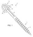
- FIG. 1illustrates one embodiment of a hammertoe implant comprising an expandable section and a threaded section.
- FIG. 2is a side-view of the hammertoe implant of FIG. 1 having the expandable section in a collapsed state.
- FIG. 3is a side-view of the hammertoe implant of FIG. 1 having the expandable section in an expanded state.
- FIG. 4illustrates one embodiment of a cutting instrument having a deployable cutting section for forming a reverse countersink in a bone.
- FIG. 5illustrates the cutting instrument of FIG. 4 having the deployable cutting section in a deployed position.
- FIG. 6illustrates one embodiment of the cutting instrument of FIG. 4 inserted into a canal formed in a bone.
- FIG. 7illustrates one embodiment of the hammertoe implant of FIG. 1 engaging a bone section in a collapsed state.
- FIG. 8illustrates one embodiment of the hammertoe implant of FIG. 1 inserted into a reverse countersink.
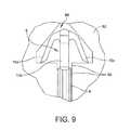
- FIG. 9illustrates an expanded view of a conical countersink having the hammertoe implant of FIG. 1 inserted therein.
- FIG. 10illustrates one embodiment of a hammertoe implant comprising an expandable section having a first arm and a second arm.
- FIG. 11illustrates one embodiment of a hammertoe implant comprising a cylindrical shaft section.
- FIG. 12illustrates one embodiment of a hammertoe implant having a first expandable section and a second expandable section.
- FIG. 13is a perspective view of the hammertoe implant of FIG. 12 in a collapsed state.
- FIG. 14is a perspective view of the hammertoe implant of FIG. 12 in an expanded state.
- FIG. 15illustrates one embodiment of a hammertoe implant having a first expandable section, a second expandable section, and a cylindrical shaft.
- FIG. 16is a perspective view of the hammertoe implant of FIG. 15 in an expanded state.
- FIG. 17illustrates the hammertoe implant of FIG. 15 inserted into a first bone and a second bone.
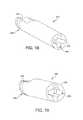
- FIG. 18illustrates one embodiment of a combination sleeve and driver configured to insert the hammertoe implant of FIG. 1 .
- FIG. 19illustrates one embodiment of a combination sleeve and driver configured to insert the hammertoe implant of FIG. 1 .
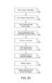
- FIG. 20illustrates a method of treating a hammertoe using a hammertoe implant.
- FIG. 21illustrates a method of treating a hammertoe using a hammertoe implant.
- the present disclosuregenerally provides a hammertoe implant and instrument for joining a first bone and a second bone, such as, for example, a proximal phalanx and a middle phalanx.
- the hammertoe implantgenerally comprises a first end and a second end coupled by a shaft. The first end is configured to couple to the first bone.
- the second endcomprises an expandable section.
- the expandable sectionis configured to couple the implant to the second bone.
- the expandable sectionexpands into a reverse countersink formed in the second bone.
- the countersinkis formed by an instrument generally comprising a shaft having an expandable cutting member formed integrally therein. The expandable cutting member is deployable from a collapsed position to an expanded position configured to form the reverse countersink in the bone.
- FIG. 1illustrates one embodiment of a hammertoe implant 2 comprising a first end 4 and a second end 8 coupled by a shaft 6 .
- the first end 4is configured to anchor the hammertoe implant 2 to a first bone.
- the first end 4comprises a threaded section 12 configured to be received within a canal formed in a first bone.
- the threaded section 12may configured to be inserted into a pre-drilled and/or pre-tapped canal and/or may comprise a self-drilling and/or self-tapping thread.
- the threaded section 12may comprise a predetermined length configured to be fully implanted into the first bone.
- the first end 4comprises other suitable mechanisms for coupling the hammertoe implant 2 to the first bone.
- the second end 8comprises an expandable section 10 .
- the expandable section 10comprises one or more expandable features.
- the expandable section 10comprises a plurality of expandable arms 10 a - 10 d .
- the expandable section 10may comprise, for example, one or more expandable cones, sleeves, threads, or any other suitable expandable feature.
- the expandable section 10is configured to transition from a collapsed position to an expanded position.
- the expandable arms 10 a - 10 dmay be arranged in any suitable configuration.
- the expandable section 10comprises four expandable arms 10 a - 10 d arranged in a plus-sign configuration having a separation angle between each of the expandable arms 10 a - 10 d of ninety degrees. It will be recognized that other configurations, including fewer or additional expandable arms and/or different angles of separation, are within the scope of the claims.
- the first end 4 and the second end 8are coupled by a shaft 6 .
- the shaft 6may comprise any suitable cross-section, such as, for example, a cylinder, square, triangle, and/or other suitable cross-section.
- the shaft 6comprises a predetermine length.
- the predetermined length of the shaft 6may be configured to provide a predetermined spacing between the first bone and the second bone when the hammertoe implant 2 is inserted.
- the shaft 6comprises a predetermined length such that there is substantially no space between the first bone and the second bone after insertion of the hammertoe implant 2 .
- the hammertoe implant 2is configured to couple the first bone to the second bone.
- the threaded section 12is inserted into the first bone by rotating the threaded section 12 into contact with the predrilled canal formed in the first bone.
- the expandable section 10is received within a cavity in the second bone.
- the cavity in the second bonecomprises a reverse countersink.
- the expandable arms 10 a - 10 dare configured to couple to a bearing surface of the reverse countersink and maintain the hammertoe implant 2 in the second bone.
- the hammertoe implant 2is configured to join a middle phalanx and a proximal phalanx.
- the hammertoe implant 2may comprise any suitable material or combination of materials.
- the hammertoe implant 2may comprise Nitinol (in either the super-elastic or shape memory state), a Titanium alloy, stainless steel, an equivalent bio-material, and/or any combination thereof.
- one or more sections of the hammertoe implant 2such as the expandable section 10 , comprises a first material, for example Nitinol, and a second section of the hammertoe implant 2 , such as the threaded section 12 , comprises a second material, for example, stainless steel.
- FIG. 2illustrates a side-view of the hammertoe implant 2 of FIG. 1 having the expandable section 10 in a collapsed state.
- the expandable arms 10 a - 10 dare compressed to a first diameter.
- the expandable end 10is sized and configured to be inserted through a canal formed in the second bone.
- the canalmay comprise an internal diameter substantially equal to the first diameter of the expandable section 10 .
- a sleeve(see FIG. 18 ) is disposed over the expandable end 10 to maintain the expandable arms 10 a - 10 d in a collapsed state prior to insertion of the expandable section 10 in the second bone.
- the expandable arms 10 a - 10 dmay be maintained in a collapsed state, for example, during insertion of the first end 4 into the first bone.
- FIG. 3illustrates a side-view of the hammertoe implant 2 of FIG. 1 having the expandable section 10 in an expanded, or deployed, state.
- the expandable arms 10 a - 10 dare allowed to flare, or expand, out to a second diameter.
- the second diameteris greater than the diameter of the canal in the second bone.
- the expandable arms 10 a - 10 dmay be biased to an expanded position.
- the second diameteris greater than or equal to a diameter of a reverse countersink formed in the second bone.
- the expandable arms 10 a - 10 dinterface with a bearing surface of the reverse countersink.
- the reverse countersink in the second boneis formed by an instrument prior to insertion of the hammertoe implant 2 into the second bone.
- FIGS. 4 and 5illustrate one embodiment of an instrument 50 configured to form a reverse countersink in the second bone.
- the instrument 50comprises an instrument tip 52 coupled to a shaft 54 .
- the shaft 54has a cutting edge 56 formed integrally therewith.
- the cutting edge 56is deployable from a collapsed state (as shown in FIG. 4 ) to a deployed state (as shown in FIG. 5 ).
- the cutting edge 56may comprise any suitable deployment mechanism such as, for example, a mechanical deployment mechanism, a hinged deployment mechanism, and/or any other suitable deployment mechanism.
- the shaft 54comprises a cavity 58 configured to receive the cutting edge 56 such that the cutting edge 56 is flush with the shaft 54 in a collapsed position.
- one or more additional cutting edges 56may be formed integrally with the shaft 54 and deployed simultaneously.
- the diameter of the shaft 54 of the instrument 50is substantially equal to the diameter of the expandable section 10 of the hammertoe implant 2 in a collapsed position.
- the cutting edge 56is configured to form a reverse countersink having a diameter that is substantially equal to or less than a diameter of the expandable section 10 of the hammertoe implant 2 in a deployed position.
- the reverse countersinkprovides a bearing surface for the expandable section 10 of the hammertoe implant 2 .
- FIG. 6illustrates one embodiment of a second bone 62 having the cutting instrument of FIG. 4 inserted therein.
- the instrument 50is inserted into a canal 65 formed in the second bone 62 to a first predetermined depth.
- the instrument tip 52 and the shaft 54position the cutting edge 56 at a second predetermined depth in the second bone 62 .
- the cutting edge 56is deployed from a collapsed position (shown in FIG. 4 ) suitable for insertion through the canal to a deployed position (shown in FIG. 5 ).
- the instrument 50is rotated about a central axis, causing the cutting edge 56 to form a reverse countersink 66 in the second bone 62 .
- the cutting edge 56may transition from a partially deployed position to a fully deployed position as bone is removed by the cutting edge 56 during rotation of the instrument 50 .
- the cutting edge 56is configured to form a conical reverse countersink 66
- the cutting edge 56may be configured to form any suitable cavity, such as, for example, a conical, square, or cylindrical countersink. After forming the reverse countersink 66 , the cutting edge 56 is transitioned from the deployed position to the collapsed position and the instrument 50 is removed from the canal 65 .
- FIG. 7illustrates the hammertoe implant 2 anchored to the first bone 60 and partially inserted into the second bone 62 .
- the first end 4 of the hammertoe implant 2is coupled to the first bone 60 by the threaded section 12 .
- the threaded section 12is inserted into a canal 68 formed in the first bone 60 .
- the canal 68may be predrilled in the first bone 60 by, for example, a drill, k-wire, and/or other suitable device and/or may be formed by the hammertoe implant 2 during insertion of the threaded section 12 .
- the threaded section 12extends within the first bone 60 to a predetermined depth. In some embodiments, the threaded section 12 may extend substantially the entire width of the first bone 60 .
- the threaded section 12is inserted to a depth such that a portion of the shaft 6 is located within the canal 68 .
- the expandable section 10is maintained in a collapsed position during insertion of the first end 4 into the first bone 60 .
- the expandable section 10may be maintained in the collapsed position by, for example, a sleeve (see FIG. 18 ) disposed over the expandable section 10 .
- the second end 8 of the hammertoe implant 2is inserted into the second bone 62 .
- the expandable section 10is inserted into a canal 65 formed in the second bone 62 .
- the canal 65applies a force to the expandable section 10 that maintains the expandable arms 10 a - 10 d in a collapsed position during insertion and allows the expandable section 10 to traverse the canal 65 .
- a gapexists between the first bone 60 and the second bone 62 as the hammertoe implant 2 has not been fully inserted into the bone 62 .
- a first length, ‘A’illustrates the distance of travel of the expandable end 10 from the initial position illustrated in FIG. 7 bearing surface of the reverse countersink.
- a second length, ‘B’illustrates the corresponding gap between the first bone 60 and the second bone 62 . Having a distance ‘A’ substantially equal to the length ‘B’ ensures the joint fully closes when the implant 2 is inserted.
- FIG. 8illustrates the hammertoe implant 2 fully inserted into the second bone 62 .
- the first bone 60 and the second bone 62are aligned and the joint therebetween is closed, forcing the expandable section 10 into the reverse countersink 66 formed in the second bone 62 .
- the expandable arms 10 a - 10 dexpand to a deployed position when inserted fully into the reverse countersink 66 .
- the expandable arms 10 a - 10 dhave a deployed diameter sufficient to expand beyond the canal 65 and to engage with a bearing surface of the reverse countersink 66 .
- the reverse countersink 66is sized such that the expandable section 10 fits within the reverse countersink with minimal or no additional space to maintain the hammertoe implant 2 in a fixed position.
- the expandable arms 10 a - 10 dcomprise an expanded diameter equal to the diameter of the reverse countersink 66 .
- the expandable arms 10 a - 10 dare biased to a diameter greater than the diameter of the reverse countersink 66 , allowing the expandable arms 10 a - 10 d to contact the inner walls of the reverse countersink 66 .
- FIG. 9illustrates an isolated view of the expandable section 10 inserted into the reverse countersink 66 .
- the expandable arms 10 a - 10 dexpand to a diameter that is substantially equal to the diameter of the reverse countersink 66 .
- the expandable arms 10 a - 10 dare biased to a diameter greater than the diameter of the cavity 66 to ensure the expandable arms 10 a - 10 d expand to the full diameter of the countersink 66 .
- the reverse countersink 66is sized and configured to receive the expandable section 10 with minimal extra space to prevent movement of the hammertoe implant 2 after installation.
- the reverse countersink 66is shown as a conical cavity, the reverse countersink 66 may comprise any suitable shape corresponding to the shape of the expandable section 10 in an expanded configuration.
- a method 600 for coupling a first bone 60 and a second bone 62is discussed.
- a canal 68is formed in the first bone 60 .
- the canal 68is sized and configured to receive a first end 4 of an hammertoe implant 2 .
- a canal 65is formed in the second bone 62 .
- the canal 65 in the second bone 62is sized and configured to receive an instrument 50 therein.
- the instrument 50is configured to form a reverse countersink 66 in the second bone 62 .
- the canal 68 in the first bone 60 and/or the canal 65 in the second bone 62may be formed using, for example, a k-wire, a drill and/or any other suitable device.
- the first bone 60comprises a proximal phalanx
- the second bone 62comprises a middle phalanx.
- the instrument 50is inserted into the canal 65 formed in the second bone 62 .
- the instrument 50comprises an instrument tip 52 and a shaft 54 .
- the instrument 50is inserted to a first predetermined depth in the canal 65 .
- the instrument 50is inserted until the instrument tip 52 contacts a closed end of the canal.
- the instrument tip 52is inserted to a first predetermined depth indicated on the instrument 52 .
- a deployable cutting edge 56is coupled to the shaft 54 .
- the instrument tip 52 and the shaft 54are configured to locate the cutting edge 56 at a second predetermined depth within the canal 65 .
- a fourth step 608the cutting edge 56 is deployed and the instrument 50 is rotated about a central axis to form a reverse countersink 66 within the second bone during a fourth step 608 .
- the cutting edge 56is collapsed against the shaft 54 and, in a fifth step 610 , the instrument 50 is removed from the canal 65 .
- a sleeve(see FIG. 18 ) is placed over an expandable section 10 of a hammertoe implant 2 .
- the sleeveis configured to compress the expandable section 10 and to provide a handle for rotating the hammertoe implant 2 .
- the sixth step 612is omitted.
- the first end 4 of the hammertoe implant 2is inserted into the canal 68 formed in the first bone 60 .
- the hammertoe implant 2may be inserted by, for example, rotatably interfacing the threaded section 12 with the canal 68 .
- the hammertoe implant 2is inserted to a predetermined depth in the first bone 60 .
- the predetermined depthmay correspond to a length of the threaded section 12 .
- the threaded section 12is configured to extend substantially through the entire width of the first bone 60 .
- a portion of the shaft 6is inserted into the canal 68 .
- the second end 4 of the hammertoe implant 2is inserted into the second bone 62 during an eighth step 616 . If a sleeve was disposed over the expandable section 10 to maintain the expandable arms 10 a - 10 d in a collapsed position, the sleeve is removed prior to insertion of the second end 4 into the second bone. In some embodiments, the expandable arms 10 a - 10 d are biased to an expanded position.
- the expandable section 10is inserted into the canal 65 formed in the second bone 62 .
- the canal 65exerts a force on the expandable arms 10 a - 10 d and forces the expandable arms 10 a - 10 d into a collapsed position.
- the expandable section 10is sized and configured to fit through the canal 65 .
- the expandable arms 10 a - 10 dhave a diameter in a collapsed position equal to or less than an internal diameter of the canal 65 .
- the expandable section 10is inserted through the canal 65 to the reverse countersink 66 formed in the second bone 62 .
- the expandable arms 10 a - 10 dassume an expanded configuration, as shown in FIGS.
- the expandable arms 10 a - 10 dinterface with a bearing surface of the reverse countersink 66 formed in the second bone 62 .
- the reverse countersink 66 and the expandable section 10 of the hammertoe implant 2are sized and configured to prevent movement of the hammertoe implant 2 after insertion of the expandable head 10 into the reverse countersink 66 .
- FIGS. 10-16illustrate additional embodiments of implants for joining a first bone 60 and a second bone 62 .
- FIGS. 10 and 11illustrate one embodiment of an implant 102 comprising an expandable section 110 having a first expandable arm 110 a and a second expandable arm 110 b .
- the implant 102is similar to the hammertoe implant 2 described in conjunction with FIGS. 1-9 .
- the implant 102is configured to couple a first bone 60 and a second bone 62 , for example, a proximal phalanx and a middle phalanx.
- FIG. 10illustrates one embodiment of an implant 102 having a square shaft 106 a .
- FIG. 11illustrates one embodiment of an implant 102 having a cylindrical shaft 106 b .
- the shaft 106may comprise any suitable cross-sectional shape.
- FIGS. 12-16illustrate embodiments of hammertoe implants 202 , 302 comprising a first expandable section 204 a , 304 a and a second expandable section 204 b , 304 b coupled by a shaft 206 , 306 .
- FIGS. 12-14illustrate one embodiment of an implant 202 having a first expandable section 204 a and a second expandable section 204 b coupled by a square shaft 206 .
- Each of the first and second expandable sections 204 a , 204 bcomprise a plurality of expandable arms 210 a - 210 d , 214 a - 214 d .
- FIGS. 12 and 13illustrate the expandable arms 210 a - 210 d , 214 a - 214 d in an expanded position.
- FIG. 14illustrates the expandable arms 210 a - 210 d , 214 a - 214 d in an expanded position.
- the expandable sections 204 a , 204 bare similar to the expandable section 10 discussed with respect to FIGS. 1-9 .
- FIGS. 15 and 16illustrate one embodiment of an implant 302 comprising a first expandable section 304 a and a second expandable section 304 b coupled by a cylindrical shaft 306 .
- Each of the expandable sections 304 a , 304 bcomprise a plurality of expandable arms 310 a - 310 d , 314 a - 314 d.
- the implants 202 , 302are configured to join a first bone to a second bone, such as, for example, a middle phalanx to a proximal phalanx.
- FIG. 17illustrates one embodiment of the implant 302 coupling a first bone 360 and a second bone 364 .
- Canals 365 a , 365 bcomprising reverse countersinks 366 a , 366 b are formed in each of the first bone 360 and the second bone 362 .
- the reverse countersinks 366 a , 366 bmay be formed by, for example, the instrument 50 described in conjunction with FIGS. 4-6 .
- the first end 304 a of the implant 302is inserted into the canal 365 a of the first bone 360 in a collapsed state.
- the canal 365 aexerts a force on the expandable arms 310 a - 310 d , maintaining the expandable arms 310 a - 310 d in a collapsed position sized and configured to slideably transition through the canal 365 a .
- the expandable section 304 areaches the reverse countersink 366 a
- the expandable arms 310 a - 310 dexpand and engage a bearing surface of the reverse countersink 366 a to maintain the implant 302 in the first bone 360 .
- the second expandable section 304 b of the implant 302is inserted into the canal 365 b formed in the second bone 362 .
- the canal 365 bcomprises a reverse countersink 366 b .
- the second end 304 b of the implant 302is inserted into the canal 365 b of the second bone 362 in a collapsed state.
- the canal 365 bforces the expandable arms 314 a - 314 d into a collapsed state during insertion of the implant 302 to allow the second end 304 b to traverse the canal 365 b .
- the expandable arms 314 a - 314 dexpand to a deployed position and engage a bearing surface of the reverse countersink 366 b .
- the first bone 360 and the second bone 362are aligned and maintained by the implant 302 .
- a method 650 for coupling a first bone 60 and a second bone 62is discussed.
- a canal 68is formed in the first bone 60 .
- a canal 65is formed in the second bone 62 .
- the canals 65 and 68are sized and configured to receive an instrument 50 therein.
- the instrument 50is configured to form a reverse countersink 66 in each of the first bone 60 and the second bone 62 .
- the canal 68 in the first bone 60 and/or the canal 65 in the second bone 62may be formed using, for example, a k-wire, a drill and/or any other suitable device.
- the first bone 60comprises a proximal phalanx
- the second bone 62comprises a middle phalanx.
- the instrument 50is inserted into the canal 65 formed in the second bone 62 .
- the instrument 50comprises an instrument tip 52 and a shaft 54 .
- the instrument 50is inserted to a first predetermined depth in the canal 65 .
- the instrument 50is inserted until the instrument tip 52 contacts a closed end of the canal.
- the instrument tip 52is inserted to a first predetermined depth indicated on the instrument 52 .
- a deployable cutting edge 56is coupled to the shaft 54 .
- the instrument tip 52 and the shaft 54are configured to locate the cutting edge 56 at a second predetermined depth within the canal 65 .
- a fourth step 658the cutting edge 56 is deployed and the instrument 50 is rotated about a central axis to form a reverse countersink 66 within the second bone during a fourth step 608 .
- the cutting edge 56is collapsed against the shaft 54 and, in a fifth step 660 , the instrument 50 is removed from the canal 65 .
- the instrumentis inserted into the canal 68 formed in the first bone 60 , the deployable cutting edge 56 is deployed, and a reverse countersink is formed in the first bone 60 .
- the deployable cutting edge 56is collapsed against the shaft 54 after forming the reverse countersink in the first bone and the instrument 50 is removed from the first bone 60 .
- a sleeve(see FIG. 18 ) is placed over the second expandable section 214 of a hammertoe implant 202 .
- the sleeveis configured to compress the second expandable section 214 and to provide a handle for gripping the hammertoe implant 2 .
- the sixth step 612is omitted.
- the first expandable end 210 of the hammertoe implant 2is inserted into the canal 68 formed in the first bone 60 .
- the canal 68exerts a force on the expandable arms 210 a - 210 d and forces the expandable arms 210 a - 210 d into a collapsed position.
- the expandable section 210is sized and configured to fit through the canal 68 .
- the expandable arms 210 a - 210 dhave a diameter in a collapsed position equal to or less than an internal diameter of the canal 68 .
- the expandable section 210is inserted through the canal 68 to the reverse countersink formed in the first bone 60 .
- the expandable arms 210 a - 210 dassume an expanded configuration.
- the expandable arms 210 a - 210 dinterface with a bearing surface of the reverse countersink formed in the first bone 60 .
- the reverse countersink and the expandable section 210 of the hammertoe implant 202are sized and configured to prevent movement of the hammertoe implant 202 after insertion of the expandable head 210 into the reverse countersink.
- the second expandable section 214 of the hammertoe implant 202is inserted into the second bone 62 during a tenth step 670 . If a sleeve was disposed over the expandable section 214 to maintain the expandable arms 214 a - 214 d in a collapsed position, the sleeve is removed prior to insertion. In some embodiments, the expandable arms 214 a - 214 d are biased to an expanded position.
- the second expandable section 214is inserted into the canal 65 formed in the second bone 62 .
- the canal 65exerts a force on the expandable arms 214 a - 214 d and forces the expandable arms 214 a - 214 d into a collapsed position.
- the second expandable section 214is sized and configured to fit through the canal 65 .
- the expandable arms 214 a - 214 dhave a diameter in a collapsed position equal to or less than an internal diameter of the canal 65 .
- the second expandable section 214is inserted through the canal 65 to the reverse countersink 66 formed in the second bone 62 .
- the expandable arms 214 a - 214 dassume an expanded configuration.
- the expandable arms 214 a - 214 dinterface with a bearing surface of the reverse countersink 66 formed in the second bone 62 .
- the reverse countersink 66 and the second expandable section 214 of the hammertoe implant 202are sized and configured to prevent movement of the hammertoe implant 202 after insertion of the second expandable section 214 into the reverse countersink 66 .
- FIG. 18illustrates one embodiment of a combination sleeve and driver configured to insert one or more embodiments of the hammertoe implant.
- the combination sleeve and driver 400is configured for use with the hammertoe implants 2 , 102 , 202 , 302 illustrated in FIGS. 1-17 .
- the combination sleeve and driver 400comprises a longitudinal sleeve 402 defining a channel 404 configured to receive an expandable section 10 of an implant 2 .
- the expandable features 10 a - 10 d of the expandable section 10are compressed against the implant 2 by the channel 404 and maintained in a collapsed position.
- the combination sleeve and driver 400comprises a driver head 406 .
- the driver head 406may comprise a quick connect feature 408 configured to attach the combination sleeve and driver 400 to a handle to drive the implant 2 .
- the quick connect feature 408 and the handlemay be configured to provide translation, rotation, and/or any other suitable movement to couple the first end 4 to the first bone.
- the internal mating features of the channel 404provide rotational control such that the implant 2 can be driver proximally or backed out distally.
- the expandable features 10 a - 10 d and the channel 404operate as an inverted Phillips head interface.
- FIG. 19illustrates an alternative embodiment of a combination sleeve and driver 500 .
- the channel 504comprises a wider opening and rounded edges to accommodate the expandable features 10 a - 10 d of the expandable side 10 .
- a bone implantcomprising a first end configured to couple to a first bone, a second end defining a first expandable section comprising at least one expandable feature, and an elongate shaft extending longitudinally between the first end and the second end.
- the first expandable sectionis sized and configured to be received within a reverse countersink formed in a second bone in a collapsed state.
- the first expandable sectionexpands within the reverse countersink such that the at least one expandable feature couples to a bearing surface of the reverse countersink.
- the first expandable sectioncomprises a plurality of expandable arms.
- the expandable sectioncomprises four expandable arms.
- the first endcomprises a threaded section.
- the threaded sectioncomprises a length sufficient to extend through a thickness of the first bone.
- the first enddefines a second expandable section comprising at least one expandable feature.
- the second expandable sectionis configured to be received within a reverse countersink formed in the first bone in a collapsed state.
- the second expandable sectionexpands within the reverse countersink such that the at least one expandable feature couples to a bearing surface of the reverse countersink.
- the second expandable sectioncomprises a plurality of expandable arms.
- the first expandable sectioncomprises a material selected from the group consisting of: Nitnol, titanium, alloy, and stainless steel.
- the first bonecomprises a proximal phalanx and the second bone comprises a middle phalanx.
- the elongate shaftextends a predetermined length such that when the first end is fully inserted into the first bone and the second end is fully inserted into the second bone there is substantially no gap between the first and second bones.
- a surgical toolcomprising a shaft sized and configured to be received within a canal formed in a bone and at least one expandable cutting edge formed integrally with the shaft.
- the expandable cutting edgecomprises a collapsed position configured for insertion into the canal and an expanded position configured to form a reverse countersink in the canal. The expandable cutting edge is deployed to the expanded position after being inserted into the canal.
- the surgical toolcomprises a conical head configured to contact an end of the canal and to space the expandable cutting edge a predetermined distance from the end of the canal.
- the at least one expandable cutting edgeis deployed by mechanical deflection.
- the at least one expandable cutting edgecomprises a hinge.
- the at least one expandable cutting edgeis configured to form the reverse countersink when the shaft is rotated.
- a method for correcting hammertoecomprises the steps of forming a first canal in a first bone, forming a second canal in a second bone, inserting a surgical instrument into the second canal, and rotating the surgical tool to form a reverse countersink in the second canal of the second bone.
- the surgical instrumentcomprises a shaft, a head located at a first end of the shaft, and an expandable cutting edge formed integrally with the shaft and deployable from a collapsed position to an expanded position.
- the methodfurther comprises inserting a first end of an implant into the first canal in the first bone.
- the methodfurther comprises inserting an second end of an implant into the second canal in the second bone.
- the second end of the implantcomprises an expandable section wherein the expandable section comprises at least one expandable feature.
- the expandable sectionis inserted through the second canal to the reverse countersink in a collapsed position.
- the at least one expandable featureexpands within the reverse countersink such that the at least one expandable feature couples to a bearing surface of the reverse countersink.
- the canalexerts a force on the expandable section to maintain the expandable section in a collapsed state during insertion.
- the at least one expandable featuredeploys when fully inserted into the reverse countersink.
- the first end of the implantcomprises a threaded section.
- Inserting the first end of the implantcomprises rotating the threaded section into engagement with the first canal.
- a method for correcting hammertoecomprises the steps of forming a first canal in a first bone, forming a second canal in a second bone, and inserting a surgical instrument into the first canal.
- the surgical instrumentcomprises a shaft, a head located at a first end of the shaft, and an expandable cutting edge formed integrally with the shaft and deployable from a collapsed position to an expanded position.
- the methodfurther comprises rotating the surgical tool to form a reverse countersink in the first canal of the first bone, inserting the surgical instrument into the second canal, and rotating the surgical tool to form a reverse countersink in the second canal of the second bone.
- the methodfurther comprises inserting a first end of an implant into the first canal in the first bone.
- the first end of the implantcomprising a first expandable section having at least one expandable feature.
- the first expandable sectionis inserted through the first canal to the reverse countersink in a collapsed position.
- the at least one expandable featureexpands within the reverse countersink such that the at least one expandable feature couples to a bearing surface of the reverse countersink.
- the first canalexerts a force on the first expandable section to maintain the first expandable section in a collapsed state during insertion.
- the at least one expandable featuredeploys when fully inserted into the reverse countersink.
- the methodfurther comprises inserting a second end of the implant into the second canal in the second bone.
- the second end of the implantcomprises a second expandable section having at least one expandable feature.
- the second expandable sectionis inserted through the second canal to the reverse countersink in a collapsed position.
- the at least one expandable featureexpands within the reverse countersink such that the at least one expandable feature couples to a bearing surface of the reverse countersink.
- the second canalexerts a force on the second expandable section to maintain the second expandable section in a collapsed state during insertion.
- the at least one expandable featuredeploys when fully inserted into the reverse countersink.
Landscapes
- Health & Medical Sciences (AREA)
- Orthopedic Medicine & Surgery (AREA)
- Life Sciences & Earth Sciences (AREA)
- Surgery (AREA)
- Animal Behavior & Ethology (AREA)
- Veterinary Medicine (AREA)
- Public Health (AREA)
- Engineering & Computer Science (AREA)
- Biomedical Technology (AREA)
- Heart & Thoracic Surgery (AREA)
- General Health & Medical Sciences (AREA)
- Molecular Biology (AREA)
- Medical Informatics (AREA)
- Nuclear Medicine, Radiotherapy & Molecular Imaging (AREA)
- Oral & Maxillofacial Surgery (AREA)
- Neurology (AREA)
- Dentistry (AREA)
- Cardiology (AREA)
- Transplantation (AREA)
- Vascular Medicine (AREA)
- Prostheses (AREA)
- Surgical Instruments (AREA)
Abstract
Description
Claims (22)
Priority Applications (1)
| Application Number | Priority Date | Filing Date | Title |
|---|---|---|---|
| US15/711,421US10299840B2 (en) | 2014-09-18 | 2017-09-21 | Hammertoe implant and instrument |
Applications Claiming Priority (1)
| Application Number | Priority Date | Filing Date | Title |
|---|---|---|---|
| PCT/US2014/056315WO2016043751A1 (en) | 2014-09-18 | 2014-09-18 | Hammertoe implant and instrument |
Related Parent Applications (1)
| Application Number | Title | Priority Date | Filing Date |
|---|---|---|---|
| PCT/US2014/056315A-371-Of-InternationalWO2016043751A1 (en) | 2014-09-18 | 2014-09-18 | Hammertoe implant and instrument |
Related Child Applications (1)
| Application Number | Title | Priority Date | Filing Date |
|---|---|---|---|
| US15/711,421ContinuationUS10299840B2 (en) | 2014-09-18 | 2017-09-21 | Hammertoe implant and instrument |
Publications (2)
| Publication Number | Publication Date |
|---|---|
| US20160081728A1 US20160081728A1 (en) | 2016-03-24 |
| US9808296B2true US9808296B2 (en) | 2017-11-07 |
Family
ID=55521933
Family Applications (2)
| Application Number | Title | Priority Date | Filing Date |
|---|---|---|---|
| US14/403,746Active2034-11-04US9808296B2 (en) | 2014-09-18 | 2014-09-18 | Hammertoe implant and instrument |
| US15/711,421ActiveUS10299840B2 (en) | 2014-09-18 | 2017-09-21 | Hammertoe implant and instrument |
Family Applications After (1)
| Application Number | Title | Priority Date | Filing Date |
|---|---|---|---|
| US15/711,421ActiveUS10299840B2 (en) | 2014-09-18 | 2017-09-21 | Hammertoe implant and instrument |
Country Status (7)
| Country | Link |
|---|---|
| US (2) | US9808296B2 (en) |
| EP (1) | EP3193788A4 (en) |
| JP (1) | JP6235724B2 (en) |
| CN (1) | CN105764449A (en) |
| AU (2) | AU2014331633B2 (en) |
| CA (1) | CA2887570C (en) |
| WO (1) | WO2016043751A1 (en) |
Cited By (5)
| Publication number | Priority date | Publication date | Assignee | Title |
|---|---|---|---|---|
| US20170100172A1 (en)* | 2011-12-12 | 2017-04-13 | Wright Medical Technology, Inc. | Fusion implant |
| US10299840B2 (en)* | 2014-09-18 | 2019-05-28 | Wright Medical Technology, Inc. | Hammertoe implant and instrument |
| US10772733B2 (en)* | 2018-03-01 | 2020-09-15 | Paragon 28, Inc. | Implants and methods of use and assembly |
| US11103293B2 (en)* | 2015-10-07 | 2021-08-31 | Arthrex, Inc. | Devices for generating and applying compression within a body |
| US11246712B2 (en)* | 2018-03-01 | 2022-02-15 | Paragon 28, Inc. | Implants, systems, and methods of use and assembly |
Families Citing this family (13)
| Publication number | Priority date | Publication date | Assignee | Title |
|---|---|---|---|---|
| US8608785B2 (en) | 2010-06-02 | 2013-12-17 | Wright Medical Technology, Inc. | Hammer toe implant with expansion portion for retrograde approach |
| US9498273B2 (en) | 2010-06-02 | 2016-11-22 | Wright Medical Technology, Inc. | Orthopedic implant kit |
| US9724138B2 (en) | 2011-09-22 | 2017-08-08 | Arthrex, Inc. | Intermedullary devices for generating and applying compression within a body |
| US8945232B2 (en) | 2012-12-31 | 2015-02-03 | Wright Medical Technology, Inc. | Ball and socket implants for correction of hammer toes and claw toes |
| US9522022B2 (en)* | 2013-11-18 | 2016-12-20 | Biomedical Enterprises, Inc. | Method and appparatus for an intramedullary implant and method of implantation therefor |
| CN105960211B (en) | 2014-12-19 | 2019-01-11 | 瑞特医疗技术公司 | Intramedullary Anchors for Interphalangeal Arthrodesis |
| US20160296342A1 (en)* | 2015-04-08 | 2016-10-13 | K2M, Inc. | Flexible spinal fixation device |
| AU2016382956A1 (en)* | 2015-12-28 | 2018-08-09 | Glenhurst Labs, Llc | Surgical devices for small bone fracture surgery |
| WO2020036865A1 (en)* | 2018-08-14 | 2020-02-20 | Arthrex, Inc. | Intramedullary implant systems and methods |
| US11504172B2 (en)* | 2018-11-01 | 2022-11-22 | Arthrex, Inc. | Variable stiffness hammertoe K-wire and methods for use |
| WO2021231329A1 (en) | 2020-05-11 | 2021-11-18 | Gensano Llc | Cannulated bone implant |
| CN111839654B (en)* | 2020-07-24 | 2022-05-20 | 中南大学湘雅医院 | Guide positioning type electric bone drill |
| CN113476130A (en)* | 2021-07-26 | 2021-10-08 | 宁波兆盈医疗器械有限公司 | Fuse bone nail |
Citations (507)
| Publication number | Priority date | Publication date | Assignee | Title |
|---|---|---|---|---|
| US321389A (en) | 1885-06-30 | Combined nail and screw | ||
| US346148A (en) | 1886-07-27 | Daniel p | ||
| US348589A (en) | 1886-09-07 | sloan | ||
| US373074A (en) | 1887-11-15 | Wood-screw | ||
| US430236A (en) | 1890-06-17 | Island | ||
| US561968A (en) | 1896-06-16 | Georges cotjlon | ||
| US736121A (en) | 1902-04-21 | 1903-08-11 | Abraham B Lipscomb | Boot-calk. |
| US821025A (en) | 1903-01-27 | 1906-05-22 | Joseph Bartlett Davies | Nail or screw for securing corrugated iron. |
| US882937A (en) | 1908-03-24 | North Bros M F G Co | Screw-eye driver. | |
| GB140983A (en) | 1919-10-27 | 1920-04-08 | Charles Louis Basham | Improvements in wood screws |
| FR736058A (en) | 1932-04-28 | 1932-11-18 | Improvements made to bolts to ensure the safety of assemblies | |
| US1966835A (en) | 1932-01-28 | 1934-07-17 | Dardelet Threadlock Corp | Fastening means |
| US2140749A (en) | 1936-08-05 | 1938-12-20 | Filshie Lead Head Nail Company | Capped nail |
| US2361107A (en) | 1944-03-08 | 1944-10-24 | Charles E Johnson | Self-locking valve tappet screw |
| US2451747A (en) | 1945-03-23 | 1948-10-19 | Ernest T Kindt | Doweled structure |
| US2490364A (en) | 1948-02-27 | 1949-12-06 | Herman H Livingston | Bone pin |
| US2600517A (en) | 1948-09-29 | 1952-06-17 | Herschel L Rushing | Tell-tale screw spike |
| FR1036978A (en) | 1951-05-11 | 1953-09-14 | Karcher Schraubenwerke G M B H | Bolt |
| US2697370A (en) | 1951-09-04 | 1954-12-21 | Linzy W Brooks | Ratchet type socket wrench |
| US2832245A (en) | 1956-02-15 | 1958-04-29 | Burrows Allen | Sponge-rubber liner for socket wrench |
| US2895368A (en) | 1955-01-21 | 1959-07-21 | Jr Paul R Trigg | Bolt having rolled grooves and recessed head to enhance uniform elongation |
| US3462765A (en) | 1967-01-06 | 1969-08-26 | Dow Corning | Surgically implantable prosthetic joint |
| US3466669A (en) | 1966-09-20 | 1969-09-16 | Univ Iowa | Intramedullary finger joint prosthesis |
| US3593342A (en) | 1969-01-27 | 1971-07-20 | Cutter Lab | Prosthetic joint |
| US3681786A (en) | 1970-07-13 | 1972-08-08 | Medical Eng Corp | Solid human prosthesis of varying consistency |
| US3739403A (en) | 1970-10-09 | 1973-06-19 | F Nicolle | Prosthetic joint having a tissue ingrowth preventive capsule |
| US3759257A (en) | 1971-03-13 | 1973-09-18 | Fischer Artur | Connector for fractured tubular bones |
| US3760802A (en) | 1971-02-26 | 1973-09-25 | Fischer Artur | Supporting device for fractured tubular bones |
| US3779239A (en) | 1971-03-13 | 1973-12-18 | Fischer Artur | Connector for fractured bones |
| US3824631A (en) | 1973-05-11 | 1974-07-23 | Sampson Corp | Bone joint fusion prosthesis |
| USD243716S (en) | 1975-07-24 | 1977-03-15 | Richards Manufacturing Company, Inc. | Great toe prosthesis |
| US4047524A (en) | 1975-04-28 | 1977-09-13 | Downs Surgical Limited | Surgical implant spinal staple |
| US4096896A (en) | 1977-04-29 | 1978-06-27 | Upson Tools, Inc. | Composite tool structure |
| JPS53128181A (en) | 1977-02-24 | 1978-11-08 | Herbert Timothy James | Screw for bonding bones |
| US4156296A (en) | 1977-04-08 | 1979-05-29 | Bio-Dynamics, Inc. | Great (large) toe prosthesis and method of implanting |
| US4170990A (en) | 1977-01-28 | 1979-10-16 | Fried. Krupp Gesellschaft Mit Beschrankter Haftung | Method for implanting and subsequently removing mechanical connecting elements from living tissue |
| US4198713A (en) | 1976-10-12 | 1980-04-22 | Swanson Alfred B | Protective member for implantable prosthesis and method of protecting the prosthesis |
| US4204284A (en) | 1977-11-16 | 1980-05-27 | Lord Corporation | Joint prosthesis with contoured pin |
| US4213208A (en) | 1977-12-05 | 1980-07-22 | Sheldon Marne | Metatarso-phalangeal joint implant |
| US4237875A (en) | 1979-02-23 | 1980-12-09 | Towmotor Corporation | Dynamic intramedullary compression nailing |
| US4262665A (en) | 1979-06-27 | 1981-04-21 | Roalstad W L | Intramedullary compression device |
| US4263903A (en) | 1979-01-08 | 1981-04-28 | Richards Manufacturing Co., Inc. | Medical staple means |
| US4275717A (en) | 1979-07-27 | 1981-06-30 | Zimmer Usa, Inc. | Intramedullary fixation device for fractured tubular bones |
| US4276660A (en) | 1979-05-25 | 1981-07-07 | Laure Prosthetics, Inc. | Carpometacarpal thumb joint |
| US4278091A (en) | 1980-02-01 | 1981-07-14 | Howmedica, Inc. | Soft tissue retainer for use with bone implants, especially bone staples |
| US4304011A (en) | 1980-08-25 | 1981-12-08 | Whelan Iii Edward J | Semi-constrained metacarpophalangeal prosthesis |
| US4321002A (en) | 1978-03-27 | 1982-03-23 | Minnesota Mining And Manufacturing Company | Medical stapling device |
| US4364382A (en) | 1979-08-23 | 1982-12-21 | Ulrich Mennen | Internal fixation device for bone fractures |
| US4367562A (en) | 1980-06-19 | 1983-01-11 | Georges Gauthier | Joint prosthesis |
| US4404874A (en) | 1980-05-02 | 1983-09-20 | Firma Hermann Werner Gmbh & Co. | Screwdriver with replaceable blade |
| GB2119655A (en) | 1982-05-06 | 1983-11-23 | Nat Res Dev | Endoprosthesis |
| US4434796A (en) | 1981-04-07 | 1984-03-06 | Vsesojuzny Nauchno-Issledovatelsky I Ispytatelny Institut Meditsinskoi Tekhniki | Surgical staple, a method of and forceps for its removal |
| US4454875A (en) | 1982-04-15 | 1984-06-19 | Techmedica, Inc. | Osteal medical staple |
| US4485816A (en) | 1981-06-25 | 1984-12-04 | Alchemia | Shape-memory surgical staple apparatus and method for use in surgical suturing |
| EP0127994A1 (en) | 1983-06-02 | 1984-12-12 | Pfizer Hospital Products Group, Inc. | Arched bridge staple |
| USD277509S (en) | 1982-07-01 | 1985-02-05 | Sutter Biomedical Inc. | Great toe metatarsal phalangeal implant |
| USD277784S (en) | 1982-06-25 | 1985-02-26 | Sutter Biomedical, Inc. | Lesser toe metatarsal phalangeal implant |
| SU1152582A1 (en) | 1982-09-24 | 1985-04-30 | Новокузнецкий институт усовершенствования врачей | Clip for osteosynthesis |
| US4516569A (en) | 1982-05-06 | 1985-05-14 | National Research Development Corporation | Intramedullary orthopaedic devices |
| JPS60145133A (en) | 1984-01-09 | 1985-07-31 | 工業技術院長 | Bone connection tool |
| US4590928A (en) | 1980-09-25 | 1986-05-27 | South African Invention Development Corporation | Surgical implant |
| USD284099S (en) | 1983-03-14 | 1986-06-03 | Sutter Bio-Medical, Inc. | Great toe metatarsal phalangeal implant |
| US4634382A (en) | 1984-06-07 | 1987-01-06 | Molten Corp. | Attachment for dental prosthesis |
| US4642122A (en) | 1986-04-02 | 1987-02-10 | Laure Prosthetics, Inc. | Toe implant |
| US4655661A (en) | 1983-12-23 | 1987-04-07 | Richter-System Gmbh & Co. Kg | Self-cutting fast construction screw |
| USD291731S (en) | 1985-05-08 | 1987-09-01 | Zimmer, Inc. | Prosthetic joint implant for a finger or toe or the like |
| US4723540A (en) | 1986-07-15 | 1988-02-09 | Gilmer Jr Raymond E | Apparatus and method for exerting and maintaining a force between two bone members |
| US4723541A (en) | 1986-05-19 | 1988-02-09 | Reese Hewitt W | Bone screw and method |
| US4731087A (en) | 1987-01-06 | 1988-03-15 | New York Society For The Relief Of The Ruptured And Crippled | Metatarsal-phalangeal prosthesis |
| FR2603794A1 (en) | 1986-09-12 | 1988-03-18 | Labourrau Jacques Philippe | Surgical staple and staple-holder for its use |
| FR2605878A1 (en) | 1986-10-30 | 1988-05-06 | Landos Applic Orthopediques Fs | Prosthesis for small joints, in particular metacarpophalangial and interphalangial joints |
| US4756711A (en) | 1985-12-24 | 1988-07-12 | Christian Mai | Self-locking prosthesis, and methods for producing and for fitting in same |
| US4759768A (en) | 1987-02-11 | 1988-07-26 | Thierry Hermann | Joint prosthesis, in particular finger joint prosthesis |
| US4790304A (en) | 1984-01-20 | 1988-12-13 | Lior Rosenberg | Self-locking pin device particularly useful for internally fixing bone fractures |
| US4865606A (en) | 1987-08-13 | 1989-09-12 | Friedrichsfeld Gmbh Keramik Und Kunststoffwerke | Endoprosthesis for a knee-joint |
| FR2628312A1 (en) | 1988-03-10 | 1989-09-15 | Lebeguec Pierre | Surgical staple or clip - is U=shape with pointed legs, flat top and curved inside joint to cross-pair provided with alternating spikes and stubs |
| EP0340159A1 (en) | 1988-04-27 | 1989-11-02 | GebràDer Sulzer Aktiengesellschaft | Dowel pin for cementless bone implants |
| US4908031A (en) | 1989-07-27 | 1990-03-13 | Dow Corning Wright | Toe implant |
| US4915092A (en) | 1985-11-05 | 1990-04-10 | Interprinderea Industria Technico-Medicala | Flexible implants for stable flexible osteosynthesis of femoral tibia fractures and working instrumentation |
| US4932974A (en) | 1989-07-06 | 1990-06-12 | Pappas Michael J | Prosthetic device with predetermined crystal orientation |
| US4940467A (en) | 1988-02-03 | 1990-07-10 | Tronzo Raymond G | Variable length fixation device |
| GB2227540A (en) | 1989-01-27 | 1990-08-01 | David Ian Quarmby | Self-countersinking screws |
| US4955916A (en) | 1989-05-01 | 1990-09-11 | Techmedica, Inc. | Thumb joint prosthesis |
| US4963144A (en) | 1989-03-17 | 1990-10-16 | Huene Donald R | Bone screw fixation assembly, bone screw therefor and method of fixation |
| FR2645735A1 (en) | 1989-04-14 | 1990-10-19 | Diebold Patrice | Metatarsophalangeal joint prosthesis for the first shaft of the foot |
| US4969909A (en) | 1987-10-27 | 1990-11-13 | Barouk Louis S | Articular prosthetic implant with temporary fixing means |
| CN1047025A (en) | 1989-04-25 | 1990-11-21 | 佩-英格瓦·布兰尼马克 | Fixing element for supporting joint mechanism of finger joint or other repaired joint |
| EP0409364A2 (en) | 1989-07-13 | 1991-01-23 | ARTOS Medizinische Produkte GmbH | Junction element for osteosynthesis |
| FR2651119A1 (en) | 1989-08-23 | 1991-03-01 | Felman Daniel | Phalangeal articular prosthesis |
| US5002563A (en) | 1990-02-22 | 1991-03-26 | Raychem Corporation | Sutures utilizing shape memory alloys |
| US5007932A (en) | 1985-01-08 | 1991-04-16 | Ngk Spark Plug Co., Ltd. | Artificial bone joint |
| US5011497A (en) | 1987-10-29 | 1991-04-30 | Atos Medical Ab | Joint prosthesis |
| US5019079A (en) | 1989-11-20 | 1991-05-28 | Zimmer, Inc. | Bone screw |
| US5029753A (en) | 1989-12-08 | 1991-07-09 | Francisco Hipon | Garage door mail drop box |
| US5037440A (en) | 1989-06-06 | 1991-08-06 | Koenig Implant, Inc. | Orthopedic toe implant |
| US5046513A (en) | 1987-05-18 | 1991-09-10 | Mitek Surgical Products, Inc. | Method for anchoring suture to bone |
| US5047059A (en) | 1987-09-28 | 1991-09-10 | Philippe Saffar | Prosthesis for metacarpopealangeal or interphalangeal articulation of the fingers |
| US5053038A (en) | 1989-08-17 | 1991-10-01 | Tenstaple, Inc. | Compression bone staple |
| US5059193A (en) | 1989-11-20 | 1991-10-22 | Spine-Tech, Inc. | Expandable spinal implant and surgical method |
| US5062851A (en) | 1989-04-25 | 1991-11-05 | Medevelop Ab | Anchoring element for supporting a joint mechanism of a finger or other reconstructed joint |
| FR2663838A1 (en) | 1990-06-29 | 1992-01-03 | Michel Jean Pierre | Implant for an arthroplasty, in particular of a glenoid cavity |
| US5089009A (en) | 1989-06-27 | 1992-02-18 | United States Surgical Corporation | Inwardly biased skin fastener |
| US5092896A (en) | 1989-09-28 | 1992-03-03 | Protek Ag | Finger joint prosthesis |
| US5108395A (en) | 1989-09-18 | 1992-04-28 | Societe De Fabrication De Materiel Orthopedique - Sofamor | Implant for anterior dorsolumbar spinal osteosynthesis, intended for the correction of kyphoses |
| US5133761A (en) | 1991-06-12 | 1992-07-28 | Research Development Foundation | Finger joint prosthesis |
| US5147363A (en) | 1989-12-21 | 1992-09-15 | Haerle Anton | Screw for use in osteosynthesis |
| WO1992017122A2 (en) | 1991-03-27 | 1992-10-15 | Rainer Baumgart | Elastic clamp |
| US5171252A (en) | 1991-02-05 | 1992-12-15 | Friedland Thomas W | Surgical fastening clip formed of a shape memory alloy, a method of making such a clip and a method of using such a clip |
| US5179915A (en) | 1992-01-06 | 1993-01-19 | Osteonics Corporation | Anatomically matching intramedullary alignment rod |
| US5190546A (en) | 1983-10-14 | 1993-03-02 | Raychem Corporation | Medical devices incorporating SIM alloy elements |
| US5199839A (en) | 1991-10-09 | 1993-04-06 | Abbott-Interfast Corporation | Fastener screw having improved installation and self-locking characteristics |
| US5207712A (en) | 1992-05-07 | 1993-05-04 | Michael Cohen | Absorbable joint implants for the lesser digits and metatarsal phalangeal joints in the surgical correction of the foot |
| US5209756A (en) | 1989-11-03 | 1993-05-11 | Bahaa Botros Seedhom | Ligament fixation staple |
| US5213347A (en) | 1991-04-29 | 1993-05-25 | Lisle Corporation | Socket driveable tap apparatus |
| EP0545830A1 (en) | 1991-12-03 | 1993-06-09 | Christian Mai | Intracortical implant, especially for ligament fixation |
| US5222975A (en) | 1992-07-13 | 1993-06-29 | Lawrence Crainich | Surgical staples |
| EP0551846A1 (en) | 1992-01-14 | 1993-07-21 | Andrea Zoli | Intramedullary pin for dynamic osteosynthesis in the femoral trochanteric region |
| US5246443A (en) | 1990-10-30 | 1993-09-21 | Christian Mai | Clip and osteosynthesis plate with dynamic compression and self-retention |
| US5281225A (en) | 1989-06-07 | 1994-01-25 | Guglielmo Vicenzi | Intramedullary pin with self-locking end for metadiaphyseal fractures of long bones |
| FR2694696A1 (en) | 1992-08-14 | 1994-02-18 | Memometal Ind | Shape-memory alloy clip for bone fractures - is made from nickel@-titanium@ alloy, and is in form of staple with two branches having contact zones and connection piece |
| US5304204A (en) | 1993-02-09 | 1994-04-19 | Ethicon, Inc. | Receiverless surgical fasteners |
| US5324307A (en) | 1990-07-06 | 1994-06-28 | American Cyanamid Company | Polymeric surgical staple |
| US5326366A (en) | 1993-02-16 | 1994-07-05 | Wright Medical Technology, Inc. | Biomechanical great toe implant |
| US5326364A (en) | 1992-12-16 | 1994-07-05 | Wright Medical Technology, Inc. | Trapezial implant |
| US5330476A (en) | 1991-11-18 | 1994-07-19 | Christophe Obry | Protective cap for an osteosynthesis pin and assembly including this cap as well as an instrument for fixing it on the pin |
| EP0611557A2 (en) | 1993-02-17 | 1994-08-24 | SMITH & NEPHEW DYONICS INC | Surgical implant & surgical kit |
| US5342396A (en) | 1993-03-02 | 1994-08-30 | Cook Melvin S | Staples |
| US5352229A (en) | 1993-05-12 | 1994-10-04 | Marlowe Goble E | Arbor press staple and washer and method for its use |
| US5354301A (en) | 1993-03-19 | 1994-10-11 | Castellano Bradley D | Hammer toe operation tool system and method |
| US5358405A (en) | 1991-06-05 | 1994-10-25 | Daigen Sangyo Inc. | Tooth fixing member and method of fixing teeth with the member |
| US5360450A (en) | 1992-03-09 | 1994-11-01 | Howmedica International Div.Ne Pfizer Italiana S.P.A. | Prosthesis for the correction of flatfoot |
| US5366479A (en) | 1991-10-18 | 1994-11-22 | United States Surgical Corporation | Surgical staple for attaching an object to body tissue |
| JPH07500520A (en) | 1992-08-25 | 1995-01-19 | ウオルセル,アレクサンドル | osteosynthesis device |
| US5395372A (en) | 1993-09-07 | 1995-03-07 | Danek Medical, Inc. | Spinal strut graft holding staple |
| US5405401A (en) | 1993-10-05 | 1995-04-11 | Orthomet, Inc. | Prosthesis for replacement of joints between long bones in the hand |
| US5405400A (en) | 1993-10-05 | 1995-04-11 | Orthomet, Inc. | Joint prosthesis enabling rotary circumduction |
| US5417692A (en) | 1994-01-04 | 1995-05-23 | Goble; E. Marlowe | Bone fixation and fusion system |
| US5425777A (en) | 1992-12-23 | 1995-06-20 | Sarkisian; James S. | Artificial finger joint |
| US5425776A (en) | 1992-05-07 | 1995-06-20 | Cohen; Michael | Method of using absorbable joint implants for the lesser digits and metatarsal phalangeal joints in the surgical correction of the foot |
| US5449359A (en) | 1991-09-05 | 1995-09-12 | Groiso; Jorge A. | Elastic clip for osteosynthesis |
| US5454814A (en) | 1992-09-02 | 1995-10-03 | Orthomed Sarl | Surgical clamp and clamp driving device |
| US5458648A (en) | 1994-02-24 | 1995-10-17 | Kinetikos Medical, Inc. | Great toe joint implant and method of implantation |
| JPH07303662A (en) | 1994-05-12 | 1995-11-21 | Hiroo Fukuyo | Connecting device for medical treatment |
| US5470230A (en) | 1994-09-30 | 1995-11-28 | Daftary; Fereidoun | Anatomical dental implant with expandable root |
| US5474557A (en) | 1993-09-21 | 1995-12-12 | Mai; Christian | Multibranch osteosynthesis clip with dynamic compression and self-retention |
| US5480447A (en) | 1992-12-15 | 1996-01-02 | International Polymer Engineering, Inc. | Joint implant |
| US5484443A (en) | 1992-01-03 | 1996-01-16 | Wright Medical Technology, Inc. | Instrument for inserting a protective sleeve into the medullary canal of a bone |
| US5498265A (en) | 1991-03-05 | 1996-03-12 | Howmedica Inc. | Screw and driver |
| FR2725126A1 (en) | 1994-10-04 | 1996-04-05 | Mai Christian | LIGAMENT IMPLANT WITH SHAPE MEMORY |
| US5507822A (en) | 1993-04-23 | 1996-04-16 | Societe Dite Jbs Societe Anonyme | Ball-and-socket jointed two-part thumb prosthesis |
| US5516248A (en) | 1994-09-07 | 1996-05-14 | Abbott-Interfast Corporation | Low torque wood screw |
| US5522903A (en) | 1993-11-10 | 1996-06-04 | Jbs S.A. | Finger prosthesis |
| US5529075A (en) | 1994-09-12 | 1996-06-25 | Clark; David | Fixation device and method for repair of pronounced hallux valgus |
| FR2728779A1 (en) | 1995-01-02 | 1996-07-05 | Caffiniere Jean Yves De | Surgical wire anchor for impacting into spongy bone tissue |
| US5536127A (en) | 1994-10-13 | 1996-07-16 | Pennig; Dietmar | Headed screw construction for use in fixing the position of an intramedullary nail |
| US5549681A (en) | 1994-04-26 | 1996-08-27 | Zsuzsa Cserhati | Articulated prosthesis |
| US5551871A (en) | 1993-03-05 | 1996-09-03 | Besselink; Petrus A. | Temperature-sensitive medical/dental apparatus |
| US5554157A (en) | 1995-07-13 | 1996-09-10 | Fastenetix, L.L.C. | Rod securing polyaxial locking screw and coupling element assembly |
| EP0738502A2 (en) | 1995-04-20 | 1996-10-23 | Halifax Orthopaedic Research Limited | Bone support to be inserted in the interior of a bone |
| US5578034A (en) | 1995-06-07 | 1996-11-26 | Danek Medical, Inc. | Apparatus for preventing screw backout in a bone plate fixation system |
| WO1996041596A1 (en) | 1995-06-13 | 1996-12-27 | Biocon Oy | Joint prosthesis |
| US5591165A (en) | 1992-11-09 | 1997-01-07 | Sofamor, S.N.C. | Apparatus and method for spinal fixation and correction of spinal deformities |
| US5595563A (en) | 1995-09-05 | 1997-01-21 | Moisdon; Roger G. F. | Method and apparatus for maintaining the position of body parts |
| USD378409S (en) | 1995-10-30 | 1997-03-11 | Michelson Gary K | Spinal fixation staple |
| US5634925A (en) | 1993-02-19 | 1997-06-03 | Alphatec Manufacturing, Inc. | Apparatus and method for spinal fixation system |
| US5643264A (en) | 1995-09-13 | 1997-07-01 | Danek Medical, Inc. | Iliac screw |
| US5645599A (en) | 1994-07-26 | 1997-07-08 | Fixano | Interspinal vertebral implant |
| FR2743490A1 (en) | 1996-01-16 | 1997-07-18 | Medinov Amp | Staple for orthopaedic surgery |
| US5669913A (en) | 1995-12-22 | 1997-09-23 | Zobel; Robert A. | Method and apparatus for smoothing an anatomical joint bearing surface during hemi-joint replacement |
| US5674297A (en) | 1995-12-08 | 1997-10-07 | Lane; Lewis B. | Metacarpophalangeal prosthesis |
| US5683466A (en) | 1996-03-26 | 1997-11-04 | Vitale; Glenn C. | Joint surface replacement system |
| US5690629A (en) | 1996-04-24 | 1997-11-25 | Acromed Corporation | Apparatus for maintaining vertebrae of a spinal column in a desired spatial relationship |
| US5702472A (en) | 1996-12-26 | 1997-12-30 | Huebner; Randall J. | Phalangeal finger joint prosthesis and method |
| US5707395A (en) | 1997-01-16 | 1998-01-13 | Li Medical Technologies, Inc. | Surgical fastener and method and apparatus for ligament repair |
| US5713903A (en) | 1991-03-22 | 1998-02-03 | United States Surgical Corporation | Orthopedic fastener |
| US5713904A (en) | 1997-02-12 | 1998-02-03 | Third Millennium Engineering, Llc | Selectively expandable sacral fixation screw-sleeve device |
| US5720753A (en) | 1991-03-22 | 1998-02-24 | United States Surgical Corporation | Orthopedic fastener |
| US5725585A (en) | 1997-02-27 | 1998-03-10 | Zobel; Robert A. | Anatomically correct great toe implant and surgical procedure for implanting the same |
| US5728127A (en) | 1995-06-27 | 1998-03-17 | Acro Med Corporation | Apparatus for maintaining vertebrae of a spinal column in a desired spatial relationship |
| US5733307A (en) | 1996-09-17 | 1998-03-31 | Amei Technologies, Inc. | Bone anchor having a suture trough |
| US5741256A (en) | 1997-01-13 | 1998-04-21 | Synthes (U.S.A.) | Helical osteosynthetic implant |
| FR2754702A1 (en) | 1996-10-18 | 1998-04-24 | Medinov Amp | DEVICE FOR SOLIDARIZING AT LEAST TWO VERTEBRAL BODIES |
| US5749916A (en) | 1997-01-21 | 1998-05-12 | Spinal Innovations | Fusion implant |
| US5769852A (en) | 1993-04-27 | 1998-06-23 | Medevelop Ab | Implantable anchoring element and anchoring assembly for prostheses |
| US5776202A (en) | 1993-09-07 | 1998-07-07 | Copf; Franz | Joint prosthesis |
| US5779707A (en) | 1992-11-13 | 1998-07-14 | Bertholet; Maurice | Link piece for bony elements |
| US5782927A (en) | 1996-11-06 | 1998-07-21 | Ascension Orthopedics, Inc. | Metacarpal-phalangeal joint replacement |
| US5785713A (en) | 1995-04-25 | 1998-07-28 | Jobe; Richard P. | Surgical fixation apparatus |
| WO1998047449A1 (en) | 1997-04-18 | 1998-10-29 | W.L. Gore & Associates, Inc. | Resorbable interposition arthroplasty implant |
| US5840078A (en) | 1995-03-01 | 1998-11-24 | Yerys; Paul | Method and apparatus for mechanical attachment of soft tissue to bone tissue |
| EP0880950A1 (en) | 1997-05-30 | 1998-12-02 | Biomat | Intervertebral cervical cage |
| US5876434A (en) | 1997-07-13 | 1999-03-02 | Litana Ltd. | Implantable medical devices of shape memory alloy |
| US5882444A (en) | 1995-05-02 | 1999-03-16 | Litana Ltd. | Manufacture of two-way shape memory devices |
| US5893850A (en) | 1996-11-12 | 1999-04-13 | Cachia; Victor V. | Bone fixation device |
| WO1999021515A1 (en) | 1997-10-27 | 1999-05-06 | University Of Florida Tissue Bank, Inc. | Segmentally demineralized bone implant |
| US5919193A (en) | 1996-03-14 | 1999-07-06 | Slavitt; Jerome A. | Method and kit for surgically correcting malformations in digits of a finger or toe |
| US5928236A (en) | 1994-07-04 | 1999-07-27 | Depuy France | Locking pin or screw device for an osteosynthesis plate or for the coaptation of bone fragments |
| US5941890A (en) | 1998-06-26 | 1999-08-24 | Ethicon Endo-Surgery, Inc. | Implantable surgical marker |
| US5951288A (en) | 1998-07-03 | 1999-09-14 | Sawa; Shlaimon T. | Self expanding dental implant and method for using the same |
| US5958159A (en) | 1997-01-16 | 1999-09-28 | Memometal Industries | Process for the production of a superelastic material out of a nickel and titanium alloy |
| GB2336415A (en) | 1998-04-14 | 1999-10-20 | Kenneth Williams | Self countersinking screw |
| US5980524A (en) | 1997-06-02 | 1999-11-09 | Innovasive Devices, Inc. | Device for repairing a meniscal tear in a knee and method |
| US5984971A (en) | 1995-02-17 | 1999-11-16 | Tecres S.P.A. | Prosthesis for metacarpal-phalangeal and interphalangeal joints in hands or feet |
| US5984970A (en) | 1996-03-13 | 1999-11-16 | Bramlet; Dale G. | Arthroplasty joint assembly |
| US6011497A (en) | 1997-04-01 | 2000-01-04 | Seagate Technology, Inc. | Location dependent maximum transition run length code with alternating code word length and efficient K constraint |
| US6030162A (en) | 1998-12-18 | 2000-02-29 | Acumed, Inc. | Axial tension screw |
| FR2783702A1 (en) | 1998-09-29 | 2000-03-31 | Maurice Bertholet | Self-locking prosthesis for bone insert has heat activated anchor flanges formed on central core |
| US6045573A (en) | 1999-01-21 | 2000-04-04 | Ethicon, Inc. | Suture anchor having multiple sutures |
| US6048343A (en) | 1999-06-02 | 2000-04-11 | Mathis; John M. | Bone screw system |
| US6048151A (en) | 1999-04-16 | 2000-04-11 | Kwee; Kim | Threaded fastener |
| FR2787313A1 (en) | 1998-12-17 | 2000-06-23 | Orsco International | Osteo-synthesis implant has shape memory material inserts to expand into contact with bone fragments |
| US6083242A (en) | 1999-02-17 | 2000-07-04 | Holobeam, Inc. | Surgical staples with deformation zones of non-uniform cross section |
| US6099571A (en) | 1997-07-16 | 2000-08-08 | Knapp; John G. | Joint prosthesis |
| US6102642A (en) | 1997-02-20 | 2000-08-15 | Yamahiro Co., Ltd. | Screw head |
| US6146387A (en) | 1998-08-26 | 2000-11-14 | Linvatec Corporation | Cannulated tissue anchor system |
| FR2794019A1 (en) | 1999-05-26 | 2000-12-01 | Orsco Internat | Ostheosynthesis implant especially useful for long and small bones, comprises body including helicoidal coil of deformable material and means of supporting implant against the proximal and distal fragments of the bone |
| US6187009B1 (en) | 1997-02-28 | 2001-02-13 | Synthes (U.S.A.) | Osteosynthesis implant |
| US6193757B1 (en) | 1998-10-29 | 2001-02-27 | Sdgi Holdings, Inc. | Expandable intervertebral spacers |
| US6197037B1 (en) | 1999-07-29 | 2001-03-06 | John Hunter Hair | Surgical fastener for joining adjacent bone portions |
| US6200330B1 (en) | 1998-11-23 | 2001-03-13 | Theodore V. Benderev | Systems for securing sutures, grafts and soft tissue to bone and periosteum |
| US6200321B1 (en) | 1998-09-10 | 2001-03-13 | Hand Innovations, Inc. | Fracture fixation system |
| US6200345B1 (en) | 1997-01-18 | 2001-03-13 | Diro, Inc. | Locking taper attachment system having improved bacterial seal |
| US6224600B1 (en) | 1996-07-10 | 2001-05-01 | G. Constantine Protogirou | Intramedullary, flexible fracture fixation device, using bi-axial prestressing |
| FR2801189A1 (en) | 1999-11-24 | 2001-05-25 | Newdeal | Bone shortening implant, especially for metatarsal bones, has anterior portion with anchoring head and posterior portion sliding into bone canal |
| US6248109B1 (en) | 1998-07-30 | 2001-06-19 | Waldemar Link (Gmbh & Co.) | Implant for interconnecting two bone fragments |
| US20010025199A1 (en) | 2000-03-21 | 2001-09-27 | Markus Rauscher | Artificial finger joint |
| US6299613B1 (en) | 1999-04-23 | 2001-10-09 | Sdgi Holdings, Inc. | Method for the correction of spinal deformities through vertebral body tethering without fusion |
| US20010028836A1 (en) | 2000-04-11 | 2001-10-11 | Jk Kabushiki Kaisha | Pull stud bolt |
| US6305053B1 (en) | 2000-02-01 | 2001-10-23 | John A. Galbreath | Cord lock |
| US6306140B1 (en) | 2001-01-17 | 2001-10-23 | Synthes (Usa) | Bone screw |
| WO2001080751A1 (en) | 2000-04-26 | 2001-11-01 | Anchor Medical Technologies, Inc. | Bone fixation system |
| US6319284B1 (en) | 2000-05-31 | 2001-11-20 | Futura Biomedical Llc | Toe implant |
| US20010049529A1 (en) | 1996-11-12 | 2001-12-06 | Cachia Victor V. | Bone fixation system |
| US6332885B1 (en) | 1998-05-07 | 2001-12-25 | Pasquale Martella | Synthesis device for orthopaedia and traumatology |
| US20020019636A1 (en) | 1999-04-23 | 2002-02-14 | James Ogilvie | Shape memory alloy sample |
| US20020022887A1 (en) | 1999-05-11 | 2002-02-21 | Huene Donald R. | Expandable implant for inter-vertebral stabilization, and a method of stabilizing vertebrae |
| US20020026194A1 (en) | 1999-04-16 | 2002-02-28 | Morrison Matthew M. | Multi-axial bone anchor system |
| US6352560B1 (en) | 1998-07-03 | 2002-03-05 | Van Straten Beheer B.V. | Joint prosthesis |
| WO2002034107A2 (en) | 2000-10-26 | 2002-05-02 | Safedrip Ltd. | Self locking intramedullary nail |
| US6383223B1 (en) | 1997-06-18 | 2002-05-07 | BAEHLER ANDRé | Endoprosthesis for a joint, especially a finger, toe or wrist joint |
| US20020055785A1 (en) | 2000-11-03 | 2002-05-09 | Finsbury (Development) Limited | Prosthesis |
| US6386877B1 (en) | 1998-07-30 | 2002-05-14 | Franz Sutter | Implant for holding and/or forming a dental prosthesis or artificial finger joint |
| US20020065561A1 (en) | 2000-11-28 | 2002-05-30 | Ogilvie William F. | Interphalangeal joint replacement |
| US20020068939A1 (en) | 1998-10-26 | 2002-06-06 | Expanding Orthopedics Inc. | Expandable orthopedic device |
| US20020072803A1 (en) | 2000-11-29 | 2002-06-13 | Saunders Gerald Anthony Briden | Metatarsophalangeal resurfacing joint |
| US6406234B2 (en) | 1998-06-04 | 2002-06-18 | Synthes (Usa) | Blind rivet with fastener |
| US20020082705A1 (en) | 2000-09-22 | 2002-06-27 | Hans-Werner Bouman | Basal finger joint implant |
| US6413260B1 (en) | 1999-08-17 | 2002-07-02 | Pioneer Laboratories, Inc. | Bone connector system |
| US6419706B1 (en) | 1997-12-19 | 2002-07-16 | Sofamor S.N.C. | Partial disc prosthesis |
| US6428634B1 (en) | 1994-03-31 | 2002-08-06 | Ormco Corporation | Ni-Ti-Nb alloy processing method and articles formed from the alloy |
| US20020111690A1 (en) | 2001-01-16 | 2002-08-15 | Hyde Edward R. | Joint prosthesis and method of implantation |
| US6436099B1 (en) | 1999-04-23 | 2002-08-20 | Sdgi Holdings, Inc. | Adjustable spinal tether |
| US20020128713A1 (en) | 1999-08-13 | 2002-09-12 | Bret Ferree | Spinal fusion cage with lordosis correction |
| US6451057B1 (en) | 2001-10-29 | 2002-09-17 | Chen Po-Quang | Spinal plate element adjusting device having a threaded engagement |
| US6454808B1 (en) | 1998-01-28 | 2002-09-24 | M-E-System Inc. | Finger joint prosthesis |
| US6458134B1 (en) | 1999-08-17 | 2002-10-01 | Pioneer Laboratories, Inc. | Bone connector system with anti-rotational feature |
| US20020165544A1 (en) | 1999-11-11 | 2002-11-07 | Stephan Perren | Radially expandable intramedullary nail |
| US20020183846A1 (en) | 1989-07-06 | 2002-12-05 | Sulzer Spine-Tech Inc. | Spinal implant |
| US6508841B2 (en) | 1993-11-01 | 2003-01-21 | Biomet, Inc. | Method and apparatus for segmental bone replacement |
| US6517543B1 (en) | 1999-08-17 | 2003-02-11 | Pioneer Laboratories, Inc. | Bone connector system with anti-rotational feature |
| US20030032961A1 (en) | 2001-07-16 | 2003-02-13 | Pelo Mark Joseph | Devices from naturally occurring biologically derived materials |
| US20030040805A1 (en) | 2001-08-27 | 2003-02-27 | Yoshitaka Minamikawa | Artificial joint |
| US6533788B1 (en) | 2001-11-01 | 2003-03-18 | Hand Innovations, Inc. | Locking device for intramedullary pin fixation |
| EP1300122A2 (en) | 2001-10-05 | 2003-04-09 | Depuy Orthopaedics, Inc. | Prosthetic joint component having multiple arcuate bending portions |
| US6551343B1 (en) | 1998-04-01 | 2003-04-22 | Bionx Implants, Oy | Bioabsorbable surgical fastener for tissue treatment |
| US6551321B1 (en) | 2000-06-23 | 2003-04-22 | Centerpulse Orthopedics Inc. | Flexible intramedullary nail |
| US6575976B2 (en) | 2000-06-12 | 2003-06-10 | Arthrex, Inc. | Expandable tissue anchor |
| US6582453B1 (en) | 2000-07-14 | 2003-06-24 | Opus Medical, Inc. | Method and apparatus for attaching connective tissues to bone using a suture anchoring device |
| US20030130660A1 (en) | 1998-10-26 | 2003-07-10 | Expanding Orthopedics, Inc. | Expandable orthopedic device |
| US20030191422A1 (en) | 2002-04-03 | 2003-10-09 | Sossong Charles E. | Claw toe straightening clamp |
| US6648890B2 (en) | 1996-11-12 | 2003-11-18 | Triage Medical, Inc. | Bone fixation system with radially extendable anchor |
| US20030233095A1 (en) | 2002-06-12 | 2003-12-18 | Urbanski Mark G. | Device and method for attaching soft tissue to bone |
| US20040010315A1 (en) | 2002-03-29 | 2004-01-15 | Song John K. | Self-expanding intervertebral device |
| US6679668B2 (en) | 2000-12-07 | 2004-01-20 | Bell South Intellectual Property Corporation | Double-ended fastener |
| US6682565B1 (en) | 1999-09-14 | 2004-01-27 | Flinders University | Joint prosthesis |
| US6685706B2 (en) | 2001-11-19 | 2004-02-03 | Triage Medical, Inc. | Proximal anchors for bone fixation system |
| US6699247B2 (en) | 1997-01-02 | 2004-03-02 | St. Francis Medical Technologies, Inc. | Spine distraction implant |
| US6706045B2 (en) | 1997-05-15 | 2004-03-16 | Howmedica Osteonics Corp. | Clamping connector for spinal fixation systems |
| FR2846545A1 (en) | 2002-10-30 | 2004-05-07 | Bouali Amara | Intramedullar osteosynthesis implant used, eg, for the fixing of finger or toe interphalangeal joints damaged by osteoarthritis, made of memory material and expanding at body temperature to provide a secure grip |
| US20040093081A1 (en) | 2001-01-15 | 2004-05-13 | Anders Nilsson | Implant for reconstruction of joints |
| US20040097941A1 (en) | 2002-11-20 | 2004-05-20 | Millennium Medical Technologies Inc. | Compression bone fragment wire |
| US20040111117A1 (en) | 2001-11-08 | 2004-06-10 | Smith & Nephew, Inc., A Delaware Corporation | Tissue repair system |
| US20040133204A1 (en) | 2001-01-27 | 2004-07-08 | Davies John Bruce Clayfield | Expandable bone nails |
| US20040138756A1 (en) | 2003-01-09 | 2004-07-15 | Nathan Reeder | Method for preparing radial and carpal bones for a wrist prosthesis |
| US6767350B1 (en) | 1998-07-25 | 2004-07-27 | Helke Lob | Fixing element for bone fragments |
| US20040220678A1 (en) | 2003-04-29 | 2004-11-04 | Chow Shew Ping | Prosthetic device and method for total joint replacement in small joint arthroplasty |
| US20040230193A1 (en) | 2003-04-18 | 2004-11-18 | Cheung Kenneth M.C. | Fixation device |
| US20040230313A1 (en) | 2001-11-29 | 2004-11-18 | Saunders Gerald A.B. | Metatarsophalangeal resurfacing joint |
| US20040230194A1 (en) | 2002-06-12 | 2004-11-18 | Urbanski Mark G. | Device and method for attaching soft tissue to bone |
| US20040249461A1 (en) | 1999-08-13 | 2004-12-09 | Ferree Bret A. | Coupled artificial disc replacements methods and apparatus |
| US6875235B2 (en) | 1999-10-08 | 2005-04-05 | Bret A. Ferree | Prosthetic joints with contained compressible resilient members |
| US20050113836A1 (en) | 2003-11-25 | 2005-05-26 | Lozier Antony J. | Expandable reamer |
| US20050119757A1 (en) | 2001-12-12 | 2005-06-02 | Michel Hassler | Trapezium or trapezometacarpal implant |
| US20050123672A1 (en) | 2003-12-03 | 2005-06-09 | Justin Daniel F. | Laser based metal deposition of implant structures |
| US20050124443A1 (en) | 2003-10-21 | 2005-06-09 | Summers John C. | T-lock broadhead and tight point matched balance point archery point system |
| US20050149031A1 (en) | 2003-11-26 | 2005-07-07 | Paul Ciccone | Cannulated fastener system |
| WO2005063149A1 (en) | 2003-12-22 | 2005-07-14 | Memometal Technologies | Interphalangeal and/or metacarpophalangeal prosthesis |
| US20050177158A1 (en) | 2004-02-09 | 2005-08-11 | Doubler Robert L. | Intramedullary screw and tang for orthopedic surgery |
| US20050187636A1 (en) | 2004-02-19 | 2005-08-25 | Graham Michael E. | Sinus tarsi implant |
| WO2005094706A1 (en) | 2004-03-31 | 2005-10-13 | Orthofix S.R.L. | Intramedullary nail comprising elements of shape-memory material |
| US20050251265A1 (en) | 2004-05-07 | 2005-11-10 | Calandruccio James H | Trapezium implant for thumb and method |
| WO2005104961A1 (en) | 2004-04-16 | 2005-11-10 | Memometal Technologies | Clamp for positioning a superelastic osteosynthesis clip |
| US20050261768A1 (en) | 2004-05-21 | 2005-11-24 | Trieu Hai H | Interspinous spacer |
| US20050283159A1 (en) | 2004-06-17 | 2005-12-22 | Bouali Amara | Intramedullary osteosynthesis implant |
| US20060052725A1 (en) | 2004-09-03 | 2006-03-09 | Santilli Albert N | Small joint orthopedic implants and their manufacture |
| US20060052878A1 (en) | 2004-08-18 | 2006-03-09 | Reinhold Schmieding | Modular joint replacement implant with hydrogel surface |
| US20060074421A1 (en) | 2003-05-08 | 2006-04-06 | Bickley Barry T | Fixation augmentation device and related techniques |
| US20060074488A1 (en) | 2004-08-23 | 2006-04-06 | Abdou M S | Bone fixation and fusion device |
| US20060074492A1 (en) | 2004-09-09 | 2006-04-06 | Theo Frey | Endoprosthesis for a metatarsophalangeal joint |
| US7037324B2 (en) | 2000-09-15 | 2006-05-02 | United States Surgical Corporation | Knotless tissue anchor |
| US7037309B2 (en) | 2001-07-05 | 2006-05-02 | Depuy (Ireland) Limted | Self-tapping screw for small-bone surgery |
| US7041106B1 (en) | 2001-06-15 | 2006-05-09 | Biomet, Inc. | Interphalangeal fusion pin |
| US20060100715A1 (en) | 2002-09-19 | 2006-05-11 | De Villiers Malan | Arthroplasty implant |
| US7044953B2 (en) | 2003-02-27 | 2006-05-16 | Stryker Leibinger Gmbh & Co. Kg | Compression bone screw |
| US20060129153A1 (en) | 2003-04-10 | 2006-06-15 | Kaj Klaue | Device for temporarily splinting toes |
| US20060149258A1 (en) | 2004-12-14 | 2006-07-06 | Sousa Joaquim P G | Surgical tool and method for fixation of ligaments |
| US20060173462A1 (en) | 2005-01-28 | 2006-08-03 | Kay David B | Orthopedic screw for use in repairing small bones |
| US20060200151A1 (en) | 2005-01-28 | 2006-09-07 | Dustin Ducharme | Orthopedic screw for use in repairing small bones |
| US7112214B2 (en) | 2002-06-25 | 2006-09-26 | Incisive Surgical, Inc. | Dynamic bioabsorbable fastener for use in wound closure |
| WO2006103598A1 (en) | 2005-03-31 | 2006-10-05 | Bächler Feintech Ag | Device for fixing a ligament |
| US20060229617A1 (en) | 2005-02-25 | 2006-10-12 | Orthomechanics Ltd. | Intramedullary devices and methods of deploying the same |
| WO2006109004A1 (en) | 2005-04-14 | 2006-10-19 | Memometal Technologies | Intramedullar osteosynthetic device of two bone parts, in particular of the hand and/or foot |
| US20060247787A1 (en) | 2003-06-27 | 2006-11-02 | Rydell Mark A | Method and system for toe arthroplasty |
| US20070038303A1 (en) | 2006-08-15 | 2007-02-15 | Ebi, L.P. | Foot/ankle implant and associated method |
| US7192445B2 (en) | 2000-12-06 | 2007-03-20 | Astra Tech Ab | Medical prosthetic devices and implants having improved biocompatibility |
| GB2430625A (en) | 2005-09-30 | 2007-04-04 | Andrew Malcolm Jackson | Joint fusion peg |
| US20070078518A1 (en) | 2005-08-22 | 2007-04-05 | Vilex, Inc. | Cannulated hemi-implant and methods of use thereof |
| US7207994B2 (en) | 2002-02-12 | 2007-04-24 | Pioneer Laboratories, Inc. | Cannulated bone screw |
| WO2007048038A2 (en) | 2005-10-21 | 2007-04-26 | Acumed Llc | Orthopedic rod with locking aperture |
| US20070106283A1 (en) | 2005-11-07 | 2007-05-10 | Garcia Saddy R | Driver assembly and fastener apparatus |
| US20070123873A1 (en) | 2005-10-31 | 2007-05-31 | Czartoski Timothy J | Intramedullary nail with oblique openings |
| US20070142920A1 (en) | 2005-12-20 | 2007-06-21 | Niemi Willard J | Metatarsal implant |
| US7240677B2 (en) | 2003-02-03 | 2007-07-10 | Biomedical Enterprises, Inc. | System and method for force, displacement, and rate control of shaped memory material implants |
| US20070177959A1 (en) | 2006-01-27 | 2007-08-02 | Panduit Corp. | Data center cabinet bonding stud |
| US20070185584A1 (en) | 2006-02-02 | 2007-08-09 | Kaufmann Robert A | Small joint hemiarthroplasty |
| US20070185583A1 (en) | 2004-06-01 | 2007-08-09 | Per-Ingvar Branemark | Joint prosthesis, use of such and a method for the application of a joint prosthesis |
| US20070198018A1 (en) | 2006-02-23 | 2007-08-23 | Lutz Biedermann | Bone anchoring device |
| US7261716B2 (en) | 1999-12-23 | 2007-08-28 | Karl Storz Gmbh & Co. Kg | Biodegradable interference screw and tool for attaching a transplant to a bone |
| US20070213831A1 (en) | 2004-07-09 | 2007-09-13 | De Cubber Jan | Finger or toe prosthesis |
| US20070239158A1 (en) | 2006-04-10 | 2007-10-11 | Sdgi Holdings, Inc. | Elastic plates for spinal fixation or stabilization |
| US7291175B1 (en) | 2005-01-06 | 2007-11-06 | David J Gordon | Metatarsal phalangeal implant with locking screw |
| WO2007135322A1 (en) | 2006-05-19 | 2007-11-29 | Memometal Technologies | Support device for a surgical implant with shape memory |
| US20070293866A1 (en) | 2006-05-12 | 2007-12-20 | Dieter Stoeckel | Bone anchor system and method of use |
| EP1870050A2 (en) | 2006-06-22 | 2007-12-26 | Textile Hi-Tec (T.H.T.) | Surgical assembly for bone repair comprising a cylindrical screw such as a Herbert screw |
| US20080039949A1 (en) | 2004-12-03 | 2008-02-14 | Larissa Meesenburg | Artificial Joint Element And Gripping Tool Equipped With The Same |
| US20080051912A1 (en) | 2004-11-08 | 2008-02-28 | Small Bone Innovations, Inc. | Metatarsal implant |
| US20080086139A1 (en) | 2006-10-04 | 2008-04-10 | Gerard Bourke | Toe deformity repair using bioabsorbable pin |
| US20080132894A1 (en) | 2006-11-16 | 2008-06-05 | Newdeal | Phalangeal arthrodesis implant, surgical kit and method for manufacturing same |
| US20080132958A1 (en) | 2006-11-30 | 2008-06-05 | Normed Medizin-Technik Vertriebs Gmbh | Orthopedic compression screw |
| US20080154385A1 (en) | 2006-06-20 | 2008-06-26 | Finsbury (Development) Limited | Prosthesis |
| US20080161919A1 (en) | 2006-10-03 | 2008-07-03 | Warsaw Orthopedic, Inc. | Dynamic Devices and Methods for Stabilizing Vertebral Members |
| CN201085677Y (en) | 2007-10-18 | 2008-07-16 | 王存平 | Hollow pressurization locking nail for femoral neck stem |
| US20080177291A1 (en) | 2006-11-01 | 2008-07-24 | Jensen David G | Orthopedic connector system |
| US20080177334A1 (en) | 2007-01-19 | 2008-07-24 | Alexa Medical, Llc | Screw and method of use |
| US20080195219A1 (en) | 2007-02-08 | 2008-08-14 | Zimmer, Inc. | Hydrogel proximal interphalangeal implant |
| US20080195215A1 (en) | 2007-02-09 | 2008-08-14 | Morton Troy N | Artificial toe joint |
| US20080221698A1 (en) | 2005-08-18 | 2008-09-11 | Mayo Foundation For Medical Education And Research | Semi-Constrained 1st Carpometacarpal Implant Arthroplasty |
| US20080221697A1 (en) | 2007-03-06 | 2008-09-11 | Robert Graser | Hemi-implant for first metatarsophalangeal joint |
| US20080221574A1 (en) | 2007-03-05 | 2008-09-11 | Cesare Cavallazzi | Method of Treating a Clavicle Fracture |
| US20080255618A1 (en) | 2007-04-13 | 2008-10-16 | Depuy Spine, Inc. | Articulating facet fusion screw |
| US20080269908A1 (en) | 2007-04-27 | 2008-10-30 | Piper Medical, Inc. | Carpometacarpal (cmc) joint arthoplasty implants and related jigs, medical kits and methods |
| US20080294204A1 (en) | 2007-03-07 | 2008-11-27 | Spineworks Medical, Inc. | Systems, methods, and devices for soft tissue attachment to bone |
| US20090005782A1 (en) | 2007-03-02 | 2009-01-01 | Chirico Paul E | Fracture Fixation System and Method |
| US20090012564A1 (en) | 2007-03-07 | 2009-01-08 | Spineworks Medical, Inc. | Transdiscal interbody fusion device and method |
| US20090036893A1 (en) | 2007-08-02 | 2009-02-05 | Proactive Orthopedic, Llc | Fixation and alignment device and method used in orthopaedic surgery |
| US20090105767A1 (en) | 2007-10-18 | 2009-04-23 | Inbone Technologies, Inc. | Total joint subsidence protector |
| US20090149891A1 (en) | 2005-07-21 | 2009-06-11 | Harry Lee | Pin site wound protection system |
| US20090163918A1 (en) | 2004-04-05 | 2009-06-25 | Mark M Levy | Expandable bone device |
| US20090171359A1 (en)* | 2007-05-02 | 2009-07-02 | Jerry Sterrett | Combined flip cutter and drill |
| JP2009160399A (en) | 2007-12-28 | 2009-07-23 | Biedermann Motech Gmbh | Implant used to stabilize vertebrae or bone |
| US20090187219A1 (en) | 2007-08-03 | 2009-07-23 | Neal Pachtman | Spinal Facet Joint Immobilization Systems and Methods |
| US7569061B2 (en) | 2004-11-16 | 2009-08-04 | Innovative Spinal Technologies, Inc. | Off-axis anchor guidance system |
| US20090204158A1 (en) | 2003-07-15 | 2009-08-13 | Spinal Generations, Llc | Method and device for delivering medicine to bone |
| US20090210016A1 (en) | 2008-02-14 | 2009-08-20 | Champagne Lloyd P | Joint fusion device |
| FR2927529A1 (en) | 2008-02-14 | 2009-08-21 | Pfaifer Patrick | Joint e.g. inter-phalangeal joint, prosthesis, for patient, has blade forming central part projecting in transverse direction, where central part is directed from side of treated joint whose flexion movement is realized on central part |
| US20090216282A1 (en) | 2007-05-18 | 2009-08-27 | Blake Doris M | Systems and methods for retaining a plate to a substrate with an asynchronous thread form |
| US7588603B2 (en) | 2003-11-05 | 2009-09-15 | Teknimed | Implantable orthesis and surgical kit for knee arthrodesis |
| US20090254190A1 (en) | 2008-01-07 | 2009-10-08 | Jamy Gannoe | System and method for trapezium bone replacement |
| US20090254189A1 (en) | 2005-10-13 | 2009-10-08 | Aptis Medical, Llc | Wrist prosthesis |
| US20090259316A1 (en) | 2008-04-15 | 2009-10-15 | Ginn Richard S | Spacer Devices and Systems for the Treatment of Spinal Stenosis and Methods for Using the Same |
| WO2009155577A2 (en) | 2008-06-19 | 2009-12-23 | Synthes Usa, Llc | Bone screw purchase augmentation implants, systems and techniques |
| US20100010637A1 (en) | 2007-02-07 | 2010-01-14 | Jean-Pierre Pequignot | Trapezo-metacarpal implant |
| US20100016982A1 (en) | 2006-12-07 | 2010-01-21 | Michael Wayne Solomons | Trapezium prosthesis |
| US20100023012A1 (en) | 2008-07-23 | 2010-01-28 | University Of Louisville Research Foundation, Inc. | Device and method to prevent hip fractures |
| US20100030221A1 (en) | 2008-08-04 | 2010-02-04 | Georg Christian | Clamping sleeve for clamping a cannulated drill and a guide wire |
| US20100049244A1 (en) | 2008-08-20 | 2010-02-25 | Tyco Healthcare Group Lp | Double threaded tissue tack |
| US20100057214A1 (en) | 2008-09-03 | 2010-03-04 | Mimedx, Inc., Corporation of the State of Florida | Arthrodesis implant for finger joints and related methods |
| US20100061825A1 (en) | 2008-09-05 | 2010-03-11 | Lisong Liu | Two-way nails, two-way screws and their mounting tools |
| FR2935601A1 (en) | 2008-09-09 | 2010-03-12 | Memometal Technologies | INTRAMEDULLARY IMPLANT RESORBABLE BETWEEN TWO BONE OR TWO BONE FRAGMENTS |
| US20100069970A1 (en) | 2008-09-16 | 2010-03-18 | Lewis Derek S | Orthopedic compression screw |
| US20100069913A1 (en)* | 2005-08-31 | 2010-03-18 | Chirico Paul E | Threaded bone filling material plunger |
| US7708759B2 (en) | 1996-09-13 | 2010-05-04 | Tendon Technology, Ltd. | Apparatus and methods for securing tendons or ligaments to bone |
| US20100121390A1 (en) | 2008-11-10 | 2010-05-13 | Acumed Llc | Partial or complete prosthetic replacement arthroplasty of the distal radioulnar joint |
| US20100125274A1 (en) | 2005-12-19 | 2010-05-20 | Stout Medical Group, L.P. | Expandable delivery device |
| US20100131014A1 (en) | 2007-03-20 | 2010-05-27 | Memometal Technologies | Osteosynthesis device |
| US20100131072A1 (en) | 2008-11-25 | 2010-05-27 | Schulte Robert C | Intra-osseus fusion system |
| US7727235B2 (en) | 2005-06-29 | 2010-06-01 | Ethicon, Inc. | Medical fixation devices with improved torsional drive head |
| US20100161068A1 (en) | 2007-07-09 | 2010-06-24 | Zrinski Ag | Prosthesis for part of a joint, with an expandable shaft |
| US20100185295A1 (en) | 2006-06-23 | 2010-07-22 | Implants International Limited | Articulation prosthesis for small bones, in particular for phalangeal, metacarpo-phalangeal or metatarso-phalangeal articulations |
| US7780701B1 (en) | 2003-08-13 | 2010-08-24 | Biomet Sports Medicine, Llc | Suture anchor |
| US7780737B2 (en) | 2004-08-09 | 2010-08-24 | Ortho Id | Ball-type triple-joint implant system for upper or lower limbs |
| US20100217325A1 (en) | 2008-11-03 | 2010-08-26 | Hochschuler Stephen H | Expandable spinal support device with attachable members and methods of use |
| US7785357B2 (en) | 2005-12-14 | 2010-08-31 | Arthrex, Inc. | Expanding plug for tendon fixation |
| US20100249942A1 (en) | 2009-03-27 | 2010-09-30 | Wright State University | Toe joint replacement models |
| US20100256639A1 (en) | 2008-06-24 | 2010-10-07 | Jeff Tyber | Fixation system, an intramedullary fixation assembly and method of use |
| US20100256770A1 (en) | 2007-11-07 | 2010-10-07 | Gs Development Ab | Artificial joint |
| US20100262254A1 (en) | 2009-04-09 | 2010-10-14 | Solana Surgical LLC | Metatarsal bone implant |
| US20100274293A1 (en) | 2009-04-28 | 2010-10-28 | Osteomed L.P. | Bone Plate with a Transfixation Screw Hole |
| US20100274256A1 (en)* | 2009-04-27 | 2010-10-28 | Smith & Nephew, Inc. | System and Method for Identifying a Landmark |
| US20100286692A1 (en) | 2008-01-22 | 2010-11-11 | Stout Medical Group, L.P. | Expandable orthopedic device and method |
| US20100292799A1 (en) | 2009-05-15 | 2010-11-18 | Noah Hansell | Method for Inserting and Positioning an Artificial Disc |
| US7837738B2 (en) | 2005-02-16 | 2010-11-23 | Swemac Orthopaedics Ab | Joint prosthesis and use of screw tool for positioning members thereof |
| US7842091B2 (en) | 2002-08-24 | 2010-11-30 | Grampian University Hospitals Nhs Trust | Implantable replacement joint |
| US20100324556A1 (en) | 2008-06-24 | 2010-12-23 | Jeff Tyber | Fixation system, an intramedullary fixation assembly and method of use |
| US20100331893A1 (en) | 2009-06-26 | 2010-12-30 | Wyatt Drake Geist | K-Wire And Method For Surgical Procedures |
| US20110004317A1 (en) | 2007-12-18 | 2011-01-06 | Hacking Adam S | Orthopaedic implants |
| US20110004255A1 (en) | 2009-02-19 | 2011-01-06 | Nextremity Solutions, Llc | Bone joining apparatus and method |
| JP2011502584A (en) | 2007-11-02 | 2011-01-27 | スタウト メディカル グループ,エル.ピー. | Expandable mounting device and method |
| US7887589B2 (en) | 2004-11-23 | 2011-02-15 | Glenn Bradley J | Minimally invasive spinal disc stabilizer and insertion tool |
| US20110066190A1 (en) | 2009-09-14 | 2011-03-17 | Konrad Schaller | Humeral Head Fixation Device for Osteoporotic Bone |
| US7909880B1 (en) | 2007-06-04 | 2011-03-22 | Grant William P | Toe cap implant |
| US7918879B2 (en) | 2002-02-25 | 2011-04-05 | Jeffrey Eric Yeung | Expandable fastener with compressive grips |
| US20110082507A1 (en) | 2005-05-13 | 2011-04-07 | Kaj Klaue | Osteosynthesis Device |
| US20110082508A1 (en) | 2009-10-02 | 2011-04-07 | Jason M. Hiatt | Apparatus and Method for Use in the Treatment of Hammertoe |
| US20110093085A1 (en) | 2007-02-09 | 2011-04-21 | Morton Troy N | Artificial joint and insert |
| US20110093075A1 (en) | 2008-04-22 | 2011-04-21 | Kinetic Spine Technologies Inc. | Artificial intervertebral spacer |
| US20110093017A1 (en) | 2009-10-15 | 2011-04-21 | Priya Prasad | Method and plate for fusing the medial column bones of the foot |
| US20110118739A1 (en) | 2008-06-24 | 2011-05-19 | Jeff Tyber | Intramedullary fixation assembly and method of use |
| US7963995B2 (en) | 2004-10-05 | 2011-06-21 | Aesculap, Inc. | Minimally invasive spine implant for restoration of motion |
| US20110160870A1 (en)* | 2009-11-30 | 2011-06-30 | Adrian Baumgartner | Expandable implant |
| US7976565B1 (en) | 2004-12-07 | 2011-07-12 | Biomet Sports Medicine, Llc | Expanding suture anchor having an actuator pin |
| US7985246B2 (en) | 2006-03-31 | 2011-07-26 | Warsaw Orthopedic, Inc. | Methods and instruments for delivering interspinous process spacers |
| US8002811B2 (en) | 2003-06-13 | 2011-08-23 | Tyco Healthcare Group Lp | Surgical fastener with predetermined resorption rate |
| US20110208252A1 (en) | 2008-08-20 | 2011-08-25 | Medizinische Universitaet Wien | Bone screw set |
| US20110257652A1 (en) | 2010-04-14 | 2011-10-20 | Arrowhead Medical Device Technologies, LLC. | Intramedullary fixation device and methods for bone fixation and stabilization |
| US8057524B2 (en) | 2004-12-07 | 2011-11-15 | Biomet Sports Medicine, Llc | Soft tissue rivet and method of use |
| US20110301653A1 (en) | 2010-06-02 | 2011-12-08 | Wright Medical Technology, Inc. | Hammer toe implant with expansion portion for retrograde approach |
| US20110301652A1 (en) | 2010-06-02 | 2011-12-08 | Wright Medical Technology, Inc. | Hammer toe implant and method |
| US20110306975A1 (en) | 2009-08-31 | 2011-12-15 | Ozics Oy | Arrangement for internal bone support |
| US20110319946A1 (en) | 2009-03-12 | 2011-12-29 | Levy Mark M | Bone implantation and stabilization assembly including deployment device |
| US20120016428A1 (en) | 2010-06-28 | 2012-01-19 | Mtp Solutions, Llc | Bunion correction method and device |
| US8118849B2 (en) | 2006-03-17 | 2012-02-21 | Tornier, Inc. | Bone screw with selectively securable washer |
| US8118839B2 (en) | 2006-11-08 | 2012-02-21 | Kyphon Sarl | Interspinous implant |
| US20120065692A1 (en) | 2010-09-10 | 2012-03-15 | Lloyd Champagne | Proximal interphalangeal fusion device |
| US20120065738A1 (en) | 2010-09-15 | 2012-03-15 | Daniel Schulman | Cortical Bone Spacers for Arthrodesis |
| US20120089197A1 (en) | 2010-10-10 | 2012-04-12 | Anderson Gregory S | Arthrodesis implant apparatus and method |
| US20120136448A1 (en) | 2008-08-29 | 2012-05-31 | Jody L Seifert | Devices and Methods for Treating Bone |
| US8197509B2 (en) | 2005-06-29 | 2012-06-12 | Depuy Mitek, Inc. | Suture anchor with improved torsional drive head |
| US20120209337A1 (en) | 2011-02-10 | 2012-08-16 | Weinstein Robert B | Method And Apparatus For Preparing And Fusion Of Small Joints |
| US8267939B2 (en) | 2008-02-28 | 2012-09-18 | Stryker Spine | Tool for implanting expandable intervertebral implant |
| US20120259419A1 (en) | 2011-04-05 | 2012-10-11 | Michael Glyn Brown | Method and apparatus for the treatment of metatarsophalangeal joint degenerative arthritis |
| US20120271362A1 (en) | 2009-10-13 | 2012-10-25 | The Royal Institution for the Advancement of Learn McGill University | Porous bone screw |
| US20120323241A1 (en) | 2011-06-17 | 2012-12-20 | Figure 8 Surgical, Inc. | Sternum band tensioner device, system and method |
| US20130030475A1 (en) | 2009-02-19 | 2013-01-31 | Nextremity Solutions, Llc | Reversible bone coupling device and method |
| EP2564799A1 (en) | 2011-08-31 | 2013-03-06 | NORMED Medizin-Technik GmbH | Surgical metatarsal compression nail |
| US20130066435A1 (en) | 2010-03-09 | 2013-03-14 | Synchro Medical | Arthrodesis implant |
| US20130066383A1 (en) | 2010-10-10 | 2013-03-14 | Gregory S. Anderson | Arthrodesis implant and buttressing apparatus and method |
| US20130079776A1 (en) | 2009-08-25 | 2013-03-28 | Paul Zwirkoski | Bone compression system |
| US20130090655A1 (en) | 2011-04-12 | 2013-04-11 | William L. Tontz | Device for Establishing Supportive Forces in the Bony Structure of a Skeleton |
| US20130096634A1 (en) | 2011-10-12 | 2013-04-18 | Sean Suh | Screw With Anchor Features |
| US20130123862A1 (en) | 2010-10-10 | 2013-05-16 | Gregory Anderson | Arthrodesis implant and buttressing apparatus and method |
| US20130131822A1 (en)* | 2011-11-17 | 2013-05-23 | Orthohelix Surgical Designs, Inc. | Hammertoe implant |
| US20130150965A1 (en) | 2011-12-12 | 2013-06-13 | Alan G. Taylor | Fusion implant |
| US8465525B2 (en) | 2004-03-09 | 2013-06-18 | DePuy Synthes Products, LLC | Posterior process dynamic spacer |
| WO2013096746A1 (en) | 2011-12-22 | 2013-06-27 | Arthrosurface Incorporated | System and method for bone fixation |
| US20130211451A1 (en) | 2012-02-09 | 2013-08-15 | Anulex Technologies, Inc. | Bone anchor and related instrumentation and methods |
| US20130226191A1 (en) | 2010-06-02 | 2013-08-29 | Wright Medical Technology, Inc. | Orthopedic implant kit |
| US8523944B2 (en) | 2008-12-31 | 2013-09-03 | Spinex Tec, Llc | Methods and apparatus for vertebral body distraction and fusion employing flexure members |
| WO2013131974A1 (en) | 2012-03-08 | 2013-09-12 | Normed Medizin-Technik Gmbh | Intramedullary locking bone screw for fixing the metatarsophalangeal joint of the big toe in foot surgery |
| US20130274814A1 (en) | 2009-02-19 | 2013-10-17 | Nextremity Solutions, Llc | Bone joining apparatus and method |
| US8591545B2 (en) | 2011-03-25 | 2013-11-26 | Smith & Nephew, Inc. | Flat suture anchor |
| US20130317559A1 (en) | 2012-05-24 | 2013-11-28 | Orthopro Llc | Systems and methods for implanting surgical implants |
| US20130325138A1 (en) | 2012-05-31 | 2013-12-05 | GraMedica | Interphalangeal Joint Implant Methods and Apparatus |
| US8616091B2 (en) | 2008-02-06 | 2013-12-31 | Process Displays | Peg board display fastener and connector |
| US20140018930A1 (en) | 2011-03-04 | 2014-01-16 | Swemac Innovation Ab | Prosthesis for arthrodhesis |
| US20140025125A1 (en) | 2012-07-18 | 2014-01-23 | Jmea Corporation | Expandable Prosthesis for a Tissue Repair System |
| US8636457B2 (en) | 2009-06-25 | 2014-01-28 | Robert W. Connors | Two-way fastener |
| US8641769B2 (en) | 2010-07-15 | 2014-02-04 | Spine Wave, Inc. | Plastically deformable inter-osseous device |
| US8647390B2 (en) | 2009-01-08 | 2014-02-11 | Memometal Technologies | Intramedullary anchoring stem for an orthopaedic implant head |
| US20140052196A1 (en) | 2011-04-13 | 2014-02-20 | Wright Medical Technology, Inc. | Hammer toe implant with living hinge and method |
| US20140107713A1 (en) | 2012-10-11 | 2014-04-17 | Normed Medizin-Technik Gmbh | Subtalar Implant |
| US20140142715A1 (en) | 2010-06-02 | 2014-05-22 | Wright Medical Technology, Inc. | Tapered, cylindrical cruciform hammer toe implant and method |
| US20140180428A1 (en) | 2012-12-21 | 2014-06-26 | Wright Medical Technology, Inc. | Percutaneous expanding hammertoe implant |
| US20140188237A1 (en) | 2012-12-27 | 2014-07-03 | Wright Medical Technology, Inc. | Device and method for fixation for bone or soft tissue deformity of digits |
| US20140188239A1 (en) | 2012-12-27 | 2014-07-03 | Wright Medical Technology, Inc. | Double thread hammertoe compression device |
| US20140188179A1 (en) | 2012-12-27 | 2014-07-03 | Wright Medical Technology, Inc. | Percutaneous flaring hammertoe fixation implant and instrument |
| EP2774556A1 (en) | 2013-03-08 | 2014-09-10 | Arthrex, Inc. | Expandable reamer |
| US20140257289A1 (en) | 2007-09-21 | 2014-09-11 | Depuy International Limited | Intramedullary rod instrument |
| US20140277185A1 (en) | 2013-03-15 | 2014-09-18 | Smith & Nephew, Inc. | Surgical fastening |
| US20140277186A1 (en) | 2013-03-13 | 2014-09-18 | Arthrex, Inc. | Drill/driver hybrid instrument for interphalangeal fusion |
| US20140276825A1 (en) | 2013-03-13 | 2014-09-18 | Arrowhead Medical Device Technologies Llc | Methods and Implants for Treating Hammertoe and Other Deformities |
| WO2014165123A1 (en) | 2013-03-13 | 2014-10-09 | Arrowhead Medical Device Technologies Llc | Hammertoe implant with enhanced gripping surfaces |
| US8888779B2 (en) | 2003-03-07 | 2014-11-18 | DePuy Synthes Products, LLC | Locking screw for an intramedullary nail |
| US8906060B2 (en) | 2009-06-24 | 2014-12-09 | Karl Storz Gmbh & Co. Kg | Method and apparatus for soft tissue fixation to bone |
| USD720072S1 (en) | 2013-02-06 | 2014-12-23 | Biomedical Enterprises, Inc. | Orthopedic implant |
| US20150012098A1 (en) | 2013-07-03 | 2015-01-08 | Spine Innovation, Inc. | Methods and apparatus for implanting an interbody device |
| US20150018954A1 (en) | 2013-07-09 | 2015-01-15 | Nlt Spine Ltd. | Orthopedic Implant with Adjustable Angle between Tissue Contact Surfaces |
| US20150073413A1 (en) | 2011-09-22 | 2015-03-12 | Mx Orthopedics, Corp. | Intermedullary devices for generating and applying compression within a body |
| US8986386B2 (en) | 2009-03-12 | 2015-03-24 | Vexim Sas | Apparatus for bone restoration of the spine and methods of use |
| US20150088266A1 (en) | 2012-12-31 | 2015-03-26 | Wright Medical Technology, Inc. | Ball and socket implants for correction of hammer toes and claw toes |
| US20150094778A1 (en) | 2013-10-01 | 2015-04-02 | Wright Medical Technology, Inc. | Hammer toe implant and method |
| US20150112342A1 (en) | 2013-10-23 | 2015-04-23 | Extremity Medical Llc | Methods for bone fixation using an intramedullary fixation implant |
| US20150141994A1 (en) | 2013-11-18 | 2015-05-21 | Biomedical Enterprises, Inc. | Method and appparatus for an intramedullary implant and method of implantation therefor |
| US20150142066A1 (en) | 2013-11-19 | 2015-05-21 | Wright Medical Technology, Inc. | Two-wire technique for installing hammertoe implant |
| US20150223849A1 (en) | 2014-02-12 | 2015-08-13 | Wright Medical Technology, Inc. | Intramedullary implant, system, and method for inserting an implant into a bone |
| US9138274B1 (en) | 2012-05-04 | 2015-09-22 | Xtraverse, LLC | Fasteners with shape changing bellows and methods using same |
| US9149268B2 (en) | 2009-07-17 | 2015-10-06 | Pivot Medical, Inc. | Method and apparatus for attaching tissue to bone, including the provision and use of a novel knotless suture anchor system |
Family Cites Families (6)
| Publication number | Priority date | Publication date | Assignee | Title |
|---|---|---|---|---|
| JPS6115867Y2 (en) | 1980-03-31 | 1986-05-16 | ||
| FR2808182B1 (en) | 2000-04-28 | 2002-10-31 | Newdeal Sa | COMPRESSION SPINDLE FOR THE SOLIDARIZATION OF PHALANGES |
| US8506617B1 (en) | 2002-06-21 | 2013-08-13 | Advanced Cardiovascular Systems, Inc. | Micronized peptide coated stent |
| US8398683B2 (en) | 2007-10-23 | 2013-03-19 | Pioneer Surgical Technology, Inc. | Rod coupling assembly and methods for bone fixation |
| US9545274B2 (en) | 2014-02-12 | 2017-01-17 | Wright Medical Technology, Inc. | Intramedullary implant, system, and method for inserting an implant into a bone |
| AU2014331633B2 (en)* | 2014-09-18 | 2017-06-22 | Wright Medical Technology, Inc | Hammertoe implant and instrument |
- 2014
- 2014-09-18AUAU2014331633Apatent/AU2014331633B2/ennot_activeCeased
- 2014-09-18CACA2887570Apatent/CA2887570C/ennot_activeExpired - Fee Related
- 2014-09-18JPJP2016544828Apatent/JP6235724B2/ennot_activeExpired - Fee Related
- 2014-09-18WOPCT/US2014/056315patent/WO2016043751A1/enactiveApplication Filing
- 2014-09-18USUS14/403,746patent/US9808296B2/enactiveActive
- 2014-09-18EPEP14861133.8Apatent/EP3193788A4/ennot_activeWithdrawn
- 2014-09-18CNCN201480042327.3Apatent/CN105764449A/enactivePending
- 2017
- 2017-08-14AUAU2017213594Apatent/AU2017213594B2/ennot_activeCeased
- 2017-09-21USUS15/711,421patent/US10299840B2/enactiveActive
Patent Citations (573)
| Publication number | Priority date | Publication date | Assignee | Title |
|---|---|---|---|---|
| US346148A (en) | 1886-07-27 | Daniel p | ||
| US348589A (en) | 1886-09-07 | sloan | ||
| US373074A (en) | 1887-11-15 | Wood-screw | ||
| US430236A (en) | 1890-06-17 | Island | ||
| US561968A (en) | 1896-06-16 | Georges cotjlon | ||
| US882937A (en) | 1908-03-24 | North Bros M F G Co | Screw-eye driver. | |
| US321389A (en) | 1885-06-30 | Combined nail and screw | ||
| US736121A (en) | 1902-04-21 | 1903-08-11 | Abraham B Lipscomb | Boot-calk. |
| US821025A (en) | 1903-01-27 | 1906-05-22 | Joseph Bartlett Davies | Nail or screw for securing corrugated iron. |
| GB140983A (en) | 1919-10-27 | 1920-04-08 | Charles Louis Basham | Improvements in wood screws |
| US1966835A (en) | 1932-01-28 | 1934-07-17 | Dardelet Threadlock Corp | Fastening means |
| FR736058A (en) | 1932-04-28 | 1932-11-18 | Improvements made to bolts to ensure the safety of assemblies | |
| US2140749A (en) | 1936-08-05 | 1938-12-20 | Filshie Lead Head Nail Company | Capped nail |
| US2361107A (en) | 1944-03-08 | 1944-10-24 | Charles E Johnson | Self-locking valve tappet screw |
| US2451747A (en) | 1945-03-23 | 1948-10-19 | Ernest T Kindt | Doweled structure |
| US2490364A (en) | 1948-02-27 | 1949-12-06 | Herman H Livingston | Bone pin |
| US2600517A (en) | 1948-09-29 | 1952-06-17 | Herschel L Rushing | Tell-tale screw spike |
| FR1036978A (en) | 1951-05-11 | 1953-09-14 | Karcher Schraubenwerke G M B H | Bolt |
| US2697370A (en) | 1951-09-04 | 1954-12-21 | Linzy W Brooks | Ratchet type socket wrench |
| US2895368A (en) | 1955-01-21 | 1959-07-21 | Jr Paul R Trigg | Bolt having rolled grooves and recessed head to enhance uniform elongation |
| US2832245A (en) | 1956-02-15 | 1958-04-29 | Burrows Allen | Sponge-rubber liner for socket wrench |
| US3466669A (en) | 1966-09-20 | 1969-09-16 | Univ Iowa | Intramedullary finger joint prosthesis |
| US3462765A (en) | 1967-01-06 | 1969-08-26 | Dow Corning | Surgically implantable prosthetic joint |
| US3593342A (en) | 1969-01-27 | 1971-07-20 | Cutter Lab | Prosthetic joint |
| US3681786A (en) | 1970-07-13 | 1972-08-08 | Medical Eng Corp | Solid human prosthesis of varying consistency |
| US3739403A (en) | 1970-10-09 | 1973-06-19 | F Nicolle | Prosthetic joint having a tissue ingrowth preventive capsule |
| US3760802A (en) | 1971-02-26 | 1973-09-25 | Fischer Artur | Supporting device for fractured tubular bones |
| US3759257A (en) | 1971-03-13 | 1973-09-18 | Fischer Artur | Connector for fractured tubular bones |
| US3779239A (en) | 1971-03-13 | 1973-12-18 | Fischer Artur | Connector for fractured bones |
| US3824631A (en) | 1973-05-11 | 1974-07-23 | Sampson Corp | Bone joint fusion prosthesis |
| US4047524A (en) | 1975-04-28 | 1977-09-13 | Downs Surgical Limited | Surgical implant spinal staple |
| USD243716S (en) | 1975-07-24 | 1977-03-15 | Richards Manufacturing Company, Inc. | Great toe prosthesis |
| US4198713A (en) | 1976-10-12 | 1980-04-22 | Swanson Alfred B | Protective member for implantable prosthesis and method of protecting the prosthesis |
| US4170990A (en) | 1977-01-28 | 1979-10-16 | Fried. Krupp Gesellschaft Mit Beschrankter Haftung | Method for implanting and subsequently removing mechanical connecting elements from living tissue |
| JPS53128181A (en) | 1977-02-24 | 1978-11-08 | Herbert Timothy James | Screw for bonding bones |
| US4175555A (en) | 1977-02-24 | 1979-11-27 | Interfix Limited | Bone screw |
| US4156296A (en) | 1977-04-08 | 1979-05-29 | Bio-Dynamics, Inc. | Great (large) toe prosthesis and method of implanting |
| US4096896A (en) | 1977-04-29 | 1978-06-27 | Upson Tools, Inc. | Composite tool structure |
| US4204284A (en) | 1977-11-16 | 1980-05-27 | Lord Corporation | Joint prosthesis with contoured pin |
| US4213208A (en) | 1977-12-05 | 1980-07-22 | Sheldon Marne | Metatarso-phalangeal joint implant |
| US4321002A (en) | 1978-03-27 | 1982-03-23 | Minnesota Mining And Manufacturing Company | Medical stapling device |
| US4263903A (en) | 1979-01-08 | 1981-04-28 | Richards Manufacturing Co., Inc. | Medical staple means |
| US4237875A (en) | 1979-02-23 | 1980-12-09 | Towmotor Corporation | Dynamic intramedullary compression nailing |
| US4276660A (en) | 1979-05-25 | 1981-07-07 | Laure Prosthetics, Inc. | Carpometacarpal thumb joint |
| US4262665A (en) | 1979-06-27 | 1981-04-21 | Roalstad W L | Intramedullary compression device |
| US4275717A (en) | 1979-07-27 | 1981-06-30 | Zimmer Usa, Inc. | Intramedullary fixation device for fractured tubular bones |
| US4364382A (en) | 1979-08-23 | 1982-12-21 | Ulrich Mennen | Internal fixation device for bone fractures |
| US4278091A (en) | 1980-02-01 | 1981-07-14 | Howmedica, Inc. | Soft tissue retainer for use with bone implants, especially bone staples |
| US4404874A (en) | 1980-05-02 | 1983-09-20 | Firma Hermann Werner Gmbh & Co. | Screwdriver with replaceable blade |
| US4367562A (en) | 1980-06-19 | 1983-01-11 | Georges Gauthier | Joint prosthesis |
| US4304011A (en) | 1980-08-25 | 1981-12-08 | Whelan Iii Edward J | Semi-constrained metacarpophalangeal prosthesis |
| US4590928A (en) | 1980-09-25 | 1986-05-27 | South African Invention Development Corporation | Surgical implant |
| US4434796A (en) | 1981-04-07 | 1984-03-06 | Vsesojuzny Nauchno-Issledovatelsky I Ispytatelny Institut Meditsinskoi Tekhniki | Surgical staple, a method of and forceps for its removal |
| US4485816A (en) | 1981-06-25 | 1984-12-04 | Alchemia | Shape-memory surgical staple apparatus and method for use in surgical suturing |
| US4454875A (en) | 1982-04-15 | 1984-06-19 | Techmedica, Inc. | Osteal medical staple |
| US4516569A (en) | 1982-05-06 | 1985-05-14 | National Research Development Corporation | Intramedullary orthopaedic devices |
| GB2119655A (en) | 1982-05-06 | 1983-11-23 | Nat Res Dev | Endoprosthesis |
| USD277784S (en) | 1982-06-25 | 1985-02-26 | Sutter Biomedical, Inc. | Lesser toe metatarsal phalangeal implant |
| USD277509S (en) | 1982-07-01 | 1985-02-05 | Sutter Biomedical Inc. | Great toe metatarsal phalangeal implant |
| SU1152582A1 (en) | 1982-09-24 | 1985-04-30 | Новокузнецкий институт усовершенствования врачей | Clip for osteosynthesis |
| USD284099S (en) | 1983-03-14 | 1986-06-03 | Sutter Bio-Medical, Inc. | Great toe metatarsal phalangeal implant |
| EP0127994A1 (en) | 1983-06-02 | 1984-12-12 | Pfizer Hospital Products Group, Inc. | Arched bridge staple |
| US4570623A (en) | 1983-06-02 | 1986-02-18 | Pfizer Hospital Products Group Inc. | Arched bridge staple |
| US5190546A (en) | 1983-10-14 | 1993-03-02 | Raychem Corporation | Medical devices incorporating SIM alloy elements |
| US4655661A (en) | 1983-12-23 | 1987-04-07 | Richter-System Gmbh & Co. Kg | Self-cutting fast construction screw |
| JPS60145133A (en) | 1984-01-09 | 1985-07-31 | 工業技術院長 | Bone connection tool |
| US4790304A (en) | 1984-01-20 | 1988-12-13 | Lior Rosenberg | Self-locking pin device particularly useful for internally fixing bone fractures |
| US4634382A (en) | 1984-06-07 | 1987-01-06 | Molten Corp. | Attachment for dental prosthesis |
| US5007932A (en) | 1985-01-08 | 1991-04-16 | Ngk Spark Plug Co., Ltd. | Artificial bone joint |
| USD291731S (en) | 1985-05-08 | 1987-09-01 | Zimmer, Inc. | Prosthetic joint implant for a finger or toe or the like |
| US4915092A (en) | 1985-11-05 | 1990-04-10 | Interprinderea Industria Technico-Medicala | Flexible implants for stable flexible osteosynthesis of femoral tibia fractures and working instrumentation |
| US4756711A (en) | 1985-12-24 | 1988-07-12 | Christian Mai | Self-locking prosthesis, and methods for producing and for fitting in same |
| US4642122A (en) | 1986-04-02 | 1987-02-10 | Laure Prosthetics, Inc. | Toe implant |
| US4723541A (en) | 1986-05-19 | 1988-02-09 | Reese Hewitt W | Bone screw and method |
| US4723540A (en) | 1986-07-15 | 1988-02-09 | Gilmer Jr Raymond E | Apparatus and method for exerting and maintaining a force between two bone members |
| FR2603794A1 (en) | 1986-09-12 | 1988-03-18 | Labourrau Jacques Philippe | Surgical staple and staple-holder for its use |
| FR2605878A1 (en) | 1986-10-30 | 1988-05-06 | Landos Applic Orthopediques Fs | Prosthesis for small joints, in particular metacarpophalangial and interphalangial joints |
| US4731087A (en) | 1987-01-06 | 1988-03-15 | New York Society For The Relief Of The Ruptured And Crippled | Metatarsal-phalangeal prosthesis |
| US4759768A (en) | 1987-02-11 | 1988-07-26 | Thierry Hermann | Joint prosthesis, in particular finger joint prosthesis |
| US5046513A (en) | 1987-05-18 | 1991-09-10 | Mitek Surgical Products, Inc. | Method for anchoring suture to bone |
| US4865606A (en) | 1987-08-13 | 1989-09-12 | Friedrichsfeld Gmbh Keramik Und Kunststoffwerke | Endoprosthesis for a knee-joint |
| US5047059A (en) | 1987-09-28 | 1991-09-10 | Philippe Saffar | Prosthesis for metacarpopealangeal or interphalangeal articulation of the fingers |
| US4969909A (en) | 1987-10-27 | 1990-11-13 | Barouk Louis S | Articular prosthetic implant with temporary fixing means |
| US5011497A (en) | 1987-10-29 | 1991-04-30 | Atos Medical Ab | Joint prosthesis |
| US4940467A (en) | 1988-02-03 | 1990-07-10 | Tronzo Raymond G | Variable length fixation device |
| FR2628312A1 (en) | 1988-03-10 | 1989-09-15 | Lebeguec Pierre | Surgical staple or clip - is U=shape with pointed legs, flat top and curved inside joint to cross-pair provided with alternating spikes and stubs |
| EP0340159A1 (en) | 1988-04-27 | 1989-11-02 | GebràDer Sulzer Aktiengesellschaft | Dowel pin for cementless bone implants |
| GB2227540A (en) | 1989-01-27 | 1990-08-01 | David Ian Quarmby | Self-countersinking screws |
| US4963144A (en) | 1989-03-17 | 1990-10-16 | Huene Donald R | Bone screw fixation assembly, bone screw therefor and method of fixation |
| FR2645735A1 (en) | 1989-04-14 | 1990-10-19 | Diebold Patrice | Metatarsophalangeal joint prosthesis for the first shaft of the foot |
| US5062851A (en) | 1989-04-25 | 1991-11-05 | Medevelop Ab | Anchoring element for supporting a joint mechanism of a finger or other reconstructed joint |
| CN1047025A (en) | 1989-04-25 | 1990-11-21 | 佩-英格瓦·布兰尼马克 | Fixing element for supporting joint mechanism of finger joint or other repaired joint |
| US4955916A (en) | 1989-05-01 | 1990-09-11 | Techmedica, Inc. | Thumb joint prosthesis |
| US5037440A (en) | 1989-06-06 | 1991-08-06 | Koenig Implant, Inc. | Orthopedic toe implant |
| US5281225A (en) | 1989-06-07 | 1994-01-25 | Guglielmo Vicenzi | Intramedullary pin with self-locking end for metadiaphyseal fractures of long bones |
| US5089009A (en) | 1989-06-27 | 1992-02-18 | United States Surgical Corporation | Inwardly biased skin fastener |
| US4932974A (en) | 1989-07-06 | 1990-06-12 | Pappas Michael J | Prosthetic device with predetermined crystal orientation |
| US20020183846A1 (en) | 1989-07-06 | 2002-12-05 | Sulzer Spine-Tech Inc. | Spinal implant |
| EP0409364A2 (en) | 1989-07-13 | 1991-01-23 | ARTOS Medizinische Produkte GmbH | Junction element for osteosynthesis |
| US4908031A (en) | 1989-07-27 | 1990-03-13 | Dow Corning Wright | Toe implant |
| US5053038A (en) | 1989-08-17 | 1991-10-01 | Tenstaple, Inc. | Compression bone staple |
| FR2651119A1 (en) | 1989-08-23 | 1991-03-01 | Felman Daniel | Phalangeal articular prosthesis |
| US5108395A (en) | 1989-09-18 | 1992-04-28 | Societe De Fabrication De Materiel Orthopedique - Sofamor | Implant for anterior dorsolumbar spinal osteosynthesis, intended for the correction of kyphoses |
| US5092896A (en) | 1989-09-28 | 1992-03-03 | Protek Ag | Finger joint prosthesis |
| US5209756A (en) | 1989-11-03 | 1993-05-11 | Bahaa Botros Seedhom | Ligament fixation staple |
| US5059193A (en) | 1989-11-20 | 1991-10-22 | Spine-Tech, Inc. | Expandable spinal implant and surgical method |
| US5019079A (en) | 1989-11-20 | 1991-05-28 | Zimmer, Inc. | Bone screw |
| US5029753A (en) | 1989-12-08 | 1991-07-09 | Francisco Hipon | Garage door mail drop box |
| US5147363A (en) | 1989-12-21 | 1992-09-15 | Haerle Anton | Screw for use in osteosynthesis |
| US5002563A (en) | 1990-02-22 | 1991-03-26 | Raychem Corporation | Sutures utilizing shape memory alloys |
| FR2663838A1 (en) | 1990-06-29 | 1992-01-03 | Michel Jean Pierre | Implant for an arthroplasty, in particular of a glenoid cavity |
| US5324307A (en) | 1990-07-06 | 1994-06-28 | American Cyanamid Company | Polymeric surgical staple |
| US5246443A (en) | 1990-10-30 | 1993-09-21 | Christian Mai | Clip and osteosynthesis plate with dynamic compression and self-retention |
| US5171252A (en) | 1991-02-05 | 1992-12-15 | Friedland Thomas W | Surgical fastening clip formed of a shape memory alloy, a method of making such a clip and a method of using such a clip |
| US5498265A (en) | 1991-03-05 | 1996-03-12 | Howmedica Inc. | Screw and driver |
| US5713903A (en) | 1991-03-22 | 1998-02-03 | United States Surgical Corporation | Orthopedic fastener |
| US5720753A (en) | 1991-03-22 | 1998-02-24 | United States Surgical Corporation | Orthopedic fastener |
| WO1992017122A2 (en) | 1991-03-27 | 1992-10-15 | Rainer Baumgart | Elastic clamp |
| US5213347A (en) | 1991-04-29 | 1993-05-25 | Lisle Corporation | Socket driveable tap apparatus |
| US5853414A (en) | 1991-05-09 | 1998-12-29 | Groiso; Jorge A. | Elastic clip for osteosynthesis |
| US5660188A (en) | 1991-05-09 | 1997-08-26 | Groiso; Jorge A. | Procedure for applying an elastic clip |
| US5358405A (en) | 1991-06-05 | 1994-10-25 | Daigen Sangyo Inc. | Tooth fixing member and method of fixing teeth with the member |
| US5133761A (en) | 1991-06-12 | 1992-07-28 | Research Development Foundation | Finger joint prosthesis |
| US5449359A (en) | 1991-09-05 | 1995-09-12 | Groiso; Jorge A. | Elastic clip for osteosynthesis |
| US5199839A (en) | 1991-10-09 | 1993-04-06 | Abbott-Interfast Corporation | Fastener screw having improved installation and self-locking characteristics |
| US5366479A (en) | 1991-10-18 | 1994-11-22 | United States Surgical Corporation | Surgical staple for attaching an object to body tissue |
| US5330476A (en) | 1991-11-18 | 1994-07-19 | Christophe Obry | Protective cap for an osteosynthesis pin and assembly including this cap as well as an instrument for fixing it on the pin |
| EP0545830A1 (en) | 1991-12-03 | 1993-06-09 | Christian Mai | Intracortical implant, especially for ligament fixation |
| US5484443A (en) | 1992-01-03 | 1996-01-16 | Wright Medical Technology, Inc. | Instrument for inserting a protective sleeve into the medullary canal of a bone |
| US5179915A (en) | 1992-01-06 | 1993-01-19 | Osteonics Corporation | Anatomically matching intramedullary alignment rod |
| EP0551846A1 (en) | 1992-01-14 | 1993-07-21 | Andrea Zoli | Intramedullary pin for dynamic osteosynthesis in the femoral trochanteric region |
| US5360450A (en) | 1992-03-09 | 1994-11-01 | Howmedica International Div.Ne Pfizer Italiana S.P.A. | Prosthesis for the correction of flatfoot |
| US5207712A (en) | 1992-05-07 | 1993-05-04 | Michael Cohen | Absorbable joint implants for the lesser digits and metatarsal phalangeal joints in the surgical correction of the foot |
| US5425776A (en) | 1992-05-07 | 1995-06-20 | Cohen; Michael | Method of using absorbable joint implants for the lesser digits and metatarsal phalangeal joints in the surgical correction of the foot |
| US5222975A (en) | 1992-07-13 | 1993-06-29 | Lawrence Crainich | Surgical staples |
| FR2694696A1 (en) | 1992-08-14 | 1994-02-18 | Memometal Ind | Shape-memory alloy clip for bone fractures - is made from nickel@-titanium@ alloy, and is in form of staple with two branches having contact zones and connection piece |
| JPH07500520A (en) | 1992-08-25 | 1995-01-19 | ウオルセル,アレクサンドル | osteosynthesis device |
| US5437674A (en) | 1992-08-25 | 1995-08-01 | Alexandre Worcel | Osteosynthesis device |
| US5454814A (en) | 1992-09-02 | 1995-10-03 | Orthomed Sarl | Surgical clamp and clamp driving device |
| US5591165A (en) | 1992-11-09 | 1997-01-07 | Sofamor, S.N.C. | Apparatus and method for spinal fixation and correction of spinal deformities |
| US5779707A (en) | 1992-11-13 | 1998-07-14 | Bertholet; Maurice | Link piece for bony elements |
| US5480447A (en) | 1992-12-15 | 1996-01-02 | International Polymer Engineering, Inc. | Joint implant |
| US5326364A (en) | 1992-12-16 | 1994-07-05 | Wright Medical Technology, Inc. | Trapezial implant |
| US5425777A (en) | 1992-12-23 | 1995-06-20 | Sarkisian; James S. | Artificial finger joint |
| US5304204A (en) | 1993-02-09 | 1994-04-19 | Ethicon, Inc. | Receiverless surgical fasteners |
| US5326366A (en) | 1993-02-16 | 1994-07-05 | Wright Medical Technology, Inc. | Biomechanical great toe implant |
| EP0611557A2 (en) | 1993-02-17 | 1994-08-24 | SMITH & NEPHEW DYONICS INC | Surgical implant & surgical kit |
| US5601558A (en) | 1993-02-17 | 1997-02-11 | Smith & Nephew Endoscopy, Inc. | Soft tissue anchors and systems for implantation |
| US5380334A (en) | 1993-02-17 | 1995-01-10 | Smith & Nephew Dyonics, Inc. | Soft tissue anchors and systems for implantation |
| EP0611557A3 (en) | 1993-02-17 | 1995-07-05 | Smith & Nephew Dyonics | Surgical implant & surgical kit. |
| US5634925A (en) | 1993-02-19 | 1997-06-03 | Alphatec Manufacturing, Inc. | Apparatus and method for spinal fixation system |
| US5342396A (en) | 1993-03-02 | 1994-08-30 | Cook Melvin S | Staples |
| US5551871A (en) | 1993-03-05 | 1996-09-03 | Besselink; Petrus A. | Temperature-sensitive medical/dental apparatus |
| US5354301A (en) | 1993-03-19 | 1994-10-11 | Castellano Bradley D | Hammer toe operation tool system and method |
| US5507822A (en) | 1993-04-23 | 1996-04-16 | Societe Dite Jbs Societe Anonyme | Ball-and-socket jointed two-part thumb prosthesis |
| US5769852A (en) | 1993-04-27 | 1998-06-23 | Medevelop Ab | Implantable anchoring element and anchoring assembly for prostheses |
| US5352229A (en) | 1993-05-12 | 1994-10-04 | Marlowe Goble E | Arbor press staple and washer and method for its use |
| US5395372A (en) | 1993-09-07 | 1995-03-07 | Danek Medical, Inc. | Spinal strut graft holding staple |
| US5776202A (en) | 1993-09-07 | 1998-07-07 | Copf; Franz | Joint prosthesis |
| US5474557A (en) | 1993-09-21 | 1995-12-12 | Mai; Christian | Multibranch osteosynthesis clip with dynamic compression and self-retention |
| US5405401A (en) | 1993-10-05 | 1995-04-11 | Orthomet, Inc. | Prosthesis for replacement of joints between long bones in the hand |
| US5405400A (en) | 1993-10-05 | 1995-04-11 | Orthomet, Inc. | Joint prosthesis enabling rotary circumduction |
| US6508841B2 (en) | 1993-11-01 | 2003-01-21 | Biomet, Inc. | Method and apparatus for segmental bone replacement |
| US5522903A (en) | 1993-11-10 | 1996-06-04 | Jbs S.A. | Finger prosthesis |
| US5417692A (en) | 1994-01-04 | 1995-05-23 | Goble; E. Marlowe | Bone fixation and fusion system |
| US5458648A (en) | 1994-02-24 | 1995-10-17 | Kinetikos Medical, Inc. | Great toe joint implant and method of implantation |
| US6428634B1 (en) | 1994-03-31 | 2002-08-06 | Ormco Corporation | Ni-Ti-Nb alloy processing method and articles formed from the alloy |
| US5549681A (en) | 1994-04-26 | 1996-08-27 | Zsuzsa Cserhati | Articulated prosthesis |
| JPH07303662A (en) | 1994-05-12 | 1995-11-21 | Hiroo Fukuyo | Connecting device for medical treatment |
| US5928236A (en) | 1994-07-04 | 1999-07-27 | Depuy France | Locking pin or screw device for an osteosynthesis plate or for the coaptation of bone fragments |
| US5645599A (en) | 1994-07-26 | 1997-07-08 | Fixano | Interspinal vertebral implant |
| US5516248A (en) | 1994-09-07 | 1996-05-14 | Abbott-Interfast Corporation | Low torque wood screw |
| US5529075A (en) | 1994-09-12 | 1996-06-25 | Clark; David | Fixation device and method for repair of pronounced hallux valgus |
| US5470230A (en) | 1994-09-30 | 1995-11-28 | Daftary; Fereidoun | Anatomical dental implant with expandable root |
| FR2725126A1 (en) | 1994-10-04 | 1996-04-05 | Mai Christian | LIGAMENT IMPLANT WITH SHAPE MEMORY |
| US5536127A (en) | 1994-10-13 | 1996-07-16 | Pennig; Dietmar | Headed screw construction for use in fixing the position of an intramedullary nail |
| FR2728779A1 (en) | 1995-01-02 | 1996-07-05 | Caffiniere Jean Yves De | Surgical wire anchor for impacting into spongy bone tissue |
| US5984971A (en) | 1995-02-17 | 1999-11-16 | Tecres S.P.A. | Prosthesis for metacarpal-phalangeal and interphalangeal joints in hands or feet |
| US5840078A (en) | 1995-03-01 | 1998-11-24 | Yerys; Paul | Method and apparatus for mechanical attachment of soft tissue to bone tissue |
| EP0738502A2 (en) | 1995-04-20 | 1996-10-23 | Halifax Orthopaedic Research Limited | Bone support to be inserted in the interior of a bone |
| US5785713A (en) | 1995-04-25 | 1998-07-28 | Jobe; Richard P. | Surgical fixation apparatus |
| US5882444A (en) | 1995-05-02 | 1999-03-16 | Litana Ltd. | Manufacture of two-way shape memory devices |
| US5578034A (en) | 1995-06-07 | 1996-11-26 | Danek Medical, Inc. | Apparatus for preventing screw backout in a bone plate fixation system |
| WO1996041596A1 (en) | 1995-06-13 | 1996-12-27 | Biocon Oy | Joint prosthesis |
| US5728127A (en) | 1995-06-27 | 1998-03-17 | Acro Med Corporation | Apparatus for maintaining vertebrae of a spinal column in a desired spatial relationship |
| US5554157A (en) | 1995-07-13 | 1996-09-10 | Fastenetix, L.L.C. | Rod securing polyaxial locking screw and coupling element assembly |
| US5595563A (en) | 1995-09-05 | 1997-01-21 | Moisdon; Roger G. F. | Method and apparatus for maintaining the position of body parts |
| US5643264A (en) | 1995-09-13 | 1997-07-01 | Danek Medical, Inc. | Iliac screw |
| USD378409S (en) | 1995-10-30 | 1997-03-11 | Michelson Gary K | Spinal fixation staple |
| US5674297A (en) | 1995-12-08 | 1997-10-07 | Lane; Lewis B. | Metacarpophalangeal prosthesis |
| US5669913A (en) | 1995-12-22 | 1997-09-23 | Zobel; Robert A. | Method and apparatus for smoothing an anatomical joint bearing surface during hemi-joint replacement |
| FR2743490A1 (en) | 1996-01-16 | 1997-07-18 | Medinov Amp | Staple for orthopaedic surgery |
| US5984970A (en) | 1996-03-13 | 1999-11-16 | Bramlet; Dale G. | Arthroplasty joint assembly |
| US6475242B1 (en) | 1996-03-13 | 2002-11-05 | Dale G. Bramlet | Arthroplasty joint assembly |
| US5919193A (en) | 1996-03-14 | 1999-07-06 | Slavitt; Jerome A. | Method and kit for surgically correcting malformations in digits of a finger or toe |
| US5683466A (en) | 1996-03-26 | 1997-11-04 | Vitale; Glenn C. | Joint surface replacement system |
| US5690629A (en) | 1996-04-24 | 1997-11-25 | Acromed Corporation | Apparatus for maintaining vertebrae of a spinal column in a desired spatial relationship |
| US6224600B1 (en) | 1996-07-10 | 2001-05-01 | G. Constantine Protogirou | Intramedullary, flexible fracture fixation device, using bi-axial prestressing |
| US7708759B2 (en) | 1996-09-13 | 2010-05-04 | Tendon Technology, Ltd. | Apparatus and methods for securing tendons or ligaments to bone |
| US5733307A (en) | 1996-09-17 | 1998-03-31 | Amei Technologies, Inc. | Bone anchor having a suture trough |
| US6336928B1 (en) | 1996-10-18 | 2002-01-08 | Depuy France | Device for securing at least two vertebrae |
| WO1998017189A1 (en) | 1996-10-18 | 1998-04-30 | Depuy France | Device for securing at least two vertebrae |
| FR2754702A1 (en) | 1996-10-18 | 1998-04-24 | Medinov Amp | DEVICE FOR SOLIDARIZING AT LEAST TWO VERTEBRAL BODIES |
| US5782927A (en) | 1996-11-06 | 1998-07-21 | Ascension Orthopedics, Inc. | Metacarpal-phalangeal joint replacement |
| US5893850A (en) | 1996-11-12 | 1999-04-13 | Cachia; Victor V. | Bone fixation device |
| US20010049529A1 (en) | 1996-11-12 | 2001-12-06 | Cachia Victor V. | Bone fixation system |
| US6648890B2 (en) | 1996-11-12 | 2003-11-18 | Triage Medical, Inc. | Bone fixation system with radially extendable anchor |
| US5702472A (en) | 1996-12-26 | 1997-12-30 | Huebner; Randall J. | Phalangeal finger joint prosthesis and method |
| US6699247B2 (en) | 1997-01-02 | 2004-03-02 | St. Francis Medical Technologies, Inc. | Spine distraction implant |
| US5741256A (en) | 1997-01-13 | 1998-04-21 | Synthes (U.S.A.) | Helical osteosynthetic implant |
| US5958159A (en) | 1997-01-16 | 1999-09-28 | Memometal Industries | Process for the production of a superelastic material out of a nickel and titanium alloy |
| US5707395A (en) | 1997-01-16 | 1998-01-13 | Li Medical Technologies, Inc. | Surgical fastener and method and apparatus for ligament repair |
| US6200345B1 (en) | 1997-01-18 | 2001-03-13 | Diro, Inc. | Locking taper attachment system having improved bacterial seal |
| US5749916A (en) | 1997-01-21 | 1998-05-12 | Spinal Innovations | Fusion implant |
| US5713904A (en) | 1997-02-12 | 1998-02-03 | Third Millennium Engineering, Llc | Selectively expandable sacral fixation screw-sleeve device |
| US6102642A (en) | 1997-02-20 | 2000-08-15 | Yamahiro Co., Ltd. | Screw head |
| US5725585A (en) | 1997-02-27 | 1998-03-10 | Zobel; Robert A. | Anatomically correct great toe implant and surgical procedure for implanting the same |
| US6187009B1 (en) | 1997-02-28 | 2001-02-13 | Synthes (U.S.A.) | Osteosynthesis implant |
| US6011497A (en) | 1997-04-01 | 2000-01-04 | Seagate Technology, Inc. | Location dependent maximum transition run length code with alternating code word length and efficient K constraint |
| US6017366A (en) | 1997-04-18 | 2000-01-25 | W. L. Gore & Associates, Inc. | Resorbable interposition arthroplasty implant |
| WO1998047449A1 (en) | 1997-04-18 | 1998-10-29 | W.L. Gore & Associates, Inc. | Resorbable interposition arthroplasty implant |
| US6706045B2 (en) | 1997-05-15 | 2004-03-16 | Howmedica Osteonics Corp. | Clamping connector for spinal fixation systems |
| EP0880950A1 (en) | 1997-05-30 | 1998-12-02 | Biomat | Intervertebral cervical cage |
| US5980524A (en) | 1997-06-02 | 1999-11-09 | Innovasive Devices, Inc. | Device for repairing a meniscal tear in a knee and method |
| US6383223B1 (en) | 1997-06-18 | 2002-05-07 | BAEHLER ANDRé | Endoprosthesis for a joint, especially a finger, toe or wrist joint |
| US5876434A (en) | 1997-07-13 | 1999-03-02 | Litana Ltd. | Implantable medical devices of shape memory alloy |
| US6099571A (en) | 1997-07-16 | 2000-08-08 | Knapp; John G. | Joint prosthesis |
| WO1999021515A1 (en) | 1997-10-27 | 1999-05-06 | University Of Florida Tissue Bank, Inc. | Segmentally demineralized bone implant |
| US6419706B1 (en) | 1997-12-19 | 2002-07-16 | Sofamor S.N.C. | Partial disc prosthesis |
| US6454808B1 (en) | 1998-01-28 | 2002-09-24 | M-E-System Inc. | Finger joint prosthesis |
| US6551343B1 (en) | 1998-04-01 | 2003-04-22 | Bionx Implants, Oy | Bioabsorbable surgical fastener for tissue treatment |
| GB2336415A (en) | 1998-04-14 | 1999-10-20 | Kenneth Williams | Self countersinking screw |
| US6332885B1 (en) | 1998-05-07 | 2001-12-25 | Pasquale Martella | Synthesis device for orthopaedia and traumatology |
| US6406234B2 (en) | 1998-06-04 | 2002-06-18 | Synthes (Usa) | Blind rivet with fastener |
| US5941890A (en) | 1998-06-26 | 1999-08-24 | Ethicon Endo-Surgery, Inc. | Implantable surgical marker |
| US5951288A (en) | 1998-07-03 | 1999-09-14 | Sawa; Shlaimon T. | Self expanding dental implant and method for using the same |
| US6352560B1 (en) | 1998-07-03 | 2002-03-05 | Van Straten Beheer B.V. | Joint prosthesis |
| US6767350B1 (en) | 1998-07-25 | 2004-07-27 | Helke Lob | Fixing element for bone fragments |
| US6386877B1 (en) | 1998-07-30 | 2002-05-14 | Franz Sutter | Implant for holding and/or forming a dental prosthesis or artificial finger joint |
| US6248109B1 (en) | 1998-07-30 | 2001-06-19 | Waldemar Link (Gmbh & Co.) | Implant for interconnecting two bone fragments |
| US6146387A (en) | 1998-08-26 | 2000-11-14 | Linvatec Corporation | Cannulated tissue anchor system |
| US6200321B1 (en) | 1998-09-10 | 2001-03-13 | Hand Innovations, Inc. | Fracture fixation system |
| FR2783702A1 (en) | 1998-09-29 | 2000-03-31 | Maurice Bertholet | Self-locking prosthesis for bone insert has heat activated anchor flanges formed on central core |
| US20030130660A1 (en) | 1998-10-26 | 2003-07-10 | Expanding Orthopedics, Inc. | Expandable orthopedic device |
| JP2004535249A (en) | 1998-10-26 | 2004-11-25 | エクスパンディング オーソペディクス インコーポレーテッド | Expandable orthopedic device |
| US20060084998A1 (en) | 1998-10-26 | 2006-04-20 | Expanding Orthopedics, Inc. | Expandable orthopedic device |
| US20020068939A1 (en) | 1998-10-26 | 2002-06-06 | Expanding Orthopedics Inc. | Expandable orthopedic device |
| US6193757B1 (en) | 1998-10-29 | 2001-02-27 | Sdgi Holdings, Inc. | Expandable intervertebral spacers |
| US6200330B1 (en) | 1998-11-23 | 2001-03-13 | Theodore V. Benderev | Systems for securing sutures, grafts and soft tissue to bone and periosteum |
| FR2787313A1 (en) | 1998-12-17 | 2000-06-23 | Orsco International | Osteo-synthesis implant has shape memory material inserts to expand into contact with bone fragments |
| US6030162A (en) | 1998-12-18 | 2000-02-29 | Acumed, Inc. | Axial tension screw |
| US6045573A (en) | 1999-01-21 | 2000-04-04 | Ethicon, Inc. | Suture anchor having multiple sutures |
| US6083242A (en) | 1999-02-17 | 2000-07-04 | Holobeam, Inc. | Surgical staples with deformation zones of non-uniform cross section |
| US20020026194A1 (en) | 1999-04-16 | 2002-02-28 | Morrison Matthew M. | Multi-axial bone anchor system |
| US6048151A (en) | 1999-04-16 | 2000-04-11 | Kwee; Kim | Threaded fastener |
| US20020019636A1 (en) | 1999-04-23 | 2002-02-14 | James Ogilvie | Shape memory alloy sample |
| US6299613B1 (en) | 1999-04-23 | 2001-10-09 | Sdgi Holdings, Inc. | Method for the correction of spinal deformities through vertebral body tethering without fusion |
| US6436099B1 (en) | 1999-04-23 | 2002-08-20 | Sdgi Holdings, Inc. | Adjustable spinal tether |
| US6773437B2 (en) | 1999-04-23 | 2004-08-10 | Sdgi Holdings, Inc. | Shape memory alloy staple |
| US20020022887A1 (en) | 1999-05-11 | 2002-02-21 | Huene Donald R. | Expandable implant for inter-vertebral stabilization, and a method of stabilizing vertebrae |
| FR2794019A1 (en) | 1999-05-26 | 2000-12-01 | Orsco Internat | Ostheosynthesis implant especially useful for long and small bones, comprises body including helicoidal coil of deformable material and means of supporting implant against the proximal and distal fragments of the bone |
| US6048343A (en) | 1999-06-02 | 2000-04-11 | Mathis; John M. | Bone screw system |
| US6197037B1 (en) | 1999-07-29 | 2001-03-06 | John Hunter Hair | Surgical fastener for joining adjacent bone portions |
| US20040249461A1 (en) | 1999-08-13 | 2004-12-09 | Ferree Bret A. | Coupled artificial disc replacements methods and apparatus |
| US20020128713A1 (en) | 1999-08-13 | 2002-09-12 | Bret Ferree | Spinal fusion cage with lordosis correction |
| US6413260B1 (en) | 1999-08-17 | 2002-07-02 | Pioneer Laboratories, Inc. | Bone connector system |
| US6517543B1 (en) | 1999-08-17 | 2003-02-11 | Pioneer Laboratories, Inc. | Bone connector system with anti-rotational feature |
| US6458134B1 (en) | 1999-08-17 | 2002-10-01 | Pioneer Laboratories, Inc. | Bone connector system with anti-rotational feature |
| US6682565B1 (en) | 1999-09-14 | 2004-01-27 | Flinders University | Joint prosthesis |
| US6875235B2 (en) | 1999-10-08 | 2005-04-05 | Bret A. Ferree | Prosthetic joints with contained compressible resilient members |
| US20020165544A1 (en) | 1999-11-11 | 2002-11-07 | Stephan Perren | Radially expandable intramedullary nail |
| FR2801189A1 (en) | 1999-11-24 | 2001-05-25 | Newdeal | Bone shortening implant, especially for metatarsal bones, has anterior portion with anchoring head and posterior portion sliding into bone canal |
| US7261716B2 (en) | 1999-12-23 | 2007-08-28 | Karl Storz Gmbh & Co. Kg | Biodegradable interference screw and tool for attaching a transplant to a bone |
| US6305053B1 (en) | 2000-02-01 | 2001-10-23 | John A. Galbreath | Cord lock |
| US20010025199A1 (en) | 2000-03-21 | 2001-09-27 | Markus Rauscher | Artificial finger joint |
| US6423097B2 (en) | 2000-03-21 | 2002-07-23 | Sulzer Orthopedics Ltd. | Artificial finger joint |
| US20010028836A1 (en) | 2000-04-11 | 2001-10-11 | Jk Kabushiki Kaisha | Pull stud bolt |
| WO2001080751A1 (en) | 2000-04-26 | 2001-11-01 | Anchor Medical Technologies, Inc. | Bone fixation system |
| US6319284B1 (en) | 2000-05-31 | 2001-11-20 | Futura Biomedical Llc | Toe implant |
| US6575976B2 (en) | 2000-06-12 | 2003-06-10 | Arthrex, Inc. | Expandable tissue anchor |
| US6551321B1 (en) | 2000-06-23 | 2003-04-22 | Centerpulse Orthopedics Inc. | Flexible intramedullary nail |
| US6582453B1 (en) | 2000-07-14 | 2003-06-24 | Opus Medical, Inc. | Method and apparatus for attaching connective tissues to bone using a suture anchoring device |
| US7037324B2 (en) | 2000-09-15 | 2006-05-02 | United States Surgical Corporation | Knotless tissue anchor |
| US20020082705A1 (en) | 2000-09-22 | 2002-06-27 | Hans-Werner Bouman | Basal finger joint implant |
| US20040102853A1 (en) | 2000-09-22 | 2004-05-27 | Hans-Werner Boumann | Basal finger joint implant |
| WO2002034107A2 (en) | 2000-10-26 | 2002-05-02 | Safedrip Ltd. | Self locking intramedullary nail |
| US6575973B1 (en) | 2000-10-26 | 2003-06-10 | Safedrip Ltd. | Self locking intramedullary nail |
| US20020055785A1 (en) | 2000-11-03 | 2002-05-09 | Finsbury (Development) Limited | Prosthesis |
| US6699292B2 (en) | 2000-11-28 | 2004-03-02 | Ascension Orthopedics, Inc. | Interphalangeal joint replacement |
| US20020065561A1 (en) | 2000-11-28 | 2002-05-30 | Ogilvie William F. | Interphalangeal joint replacement |
| US20020072803A1 (en) | 2000-11-29 | 2002-06-13 | Saunders Gerald Anthony Briden | Metatarsophalangeal resurfacing joint |
| US7192445B2 (en) | 2000-12-06 | 2007-03-20 | Astra Tech Ab | Medical prosthetic devices and implants having improved biocompatibility |
| US6679668B2 (en) | 2000-12-07 | 2004-01-20 | Bell South Intellectual Property Corporation | Double-ended fastener |
| US7037342B2 (en) | 2001-01-15 | 2006-05-02 | Artimplant Ab | Implant for reconstruction of joints |
| US20040093081A1 (en) | 2001-01-15 | 2004-05-13 | Anders Nilsson | Implant for reconstruction of joints |
| US20020111690A1 (en) | 2001-01-16 | 2002-08-15 | Hyde Edward R. | Joint prosthesis and method of implantation |
| US6306140B1 (en) | 2001-01-17 | 2001-10-23 | Synthes (Usa) | Bone screw |
| US20040133204A1 (en) | 2001-01-27 | 2004-07-08 | Davies John Bruce Clayfield | Expandable bone nails |
| US7041106B1 (en) | 2001-06-15 | 2006-05-09 | Biomet, Inc. | Interphalangeal fusion pin |
| US7037309B2 (en) | 2001-07-05 | 2006-05-02 | Depuy (Ireland) Limted | Self-tapping screw for small-bone surgery |
| US8337537B2 (en) | 2001-07-16 | 2012-12-25 | Depuy Products, Inc. | Device from naturally occurring biologically derived materials |
| US20040220574A1 (en) | 2001-07-16 | 2004-11-04 | Pelo Mark Joseph | Device from naturally occuring biologically derived materials |
| US20030032961A1 (en) | 2001-07-16 | 2003-02-13 | Pelo Mark Joseph | Devices from naturally occurring biologically derived materials |
| US6811568B2 (en) | 2001-08-27 | 2004-11-02 | Aidall International Ltd. | Artificial joint |
| US20030040805A1 (en) | 2001-08-27 | 2003-02-27 | Yoshitaka Minamikawa | Artificial joint |
| US20030069645A1 (en) | 2001-10-05 | 2003-04-10 | Ball Robert J. | Prosthetic joint component having multiple arcuate bending portions |
| EP1300122A2 (en) | 2001-10-05 | 2003-04-09 | Depuy Orthopaedics, Inc. | Prosthetic joint component having multiple arcuate bending portions |
| US6869449B2 (en) | 2001-10-05 | 2005-03-22 | Depuy Orthopaedics, Inc. | Prosthetic joint component having multiple arcuate bending portions |
| US6451057B1 (en) | 2001-10-29 | 2002-09-17 | Chen Po-Quang | Spinal plate element adjusting device having a threaded engagement |
| US6533788B1 (en) | 2001-11-01 | 2003-03-18 | Hand Innovations, Inc. | Locking device for intramedullary pin fixation |
| US20040111117A1 (en) | 2001-11-08 | 2004-06-10 | Smith & Nephew, Inc., A Delaware Corporation | Tissue repair system |
| US6685706B2 (en) | 2001-11-19 | 2004-02-03 | Triage Medical, Inc. | Proximal anchors for bone fixation system |
| US20040230313A1 (en) | 2001-11-29 | 2004-11-18 | Saunders Gerald A.B. | Metatarsophalangeal resurfacing joint |
| US7182787B2 (en) | 2001-12-12 | 2007-02-27 | Bioprofile | Trapezium or trapezometacarpal implant |
| US20070123993A1 (en) | 2001-12-12 | 2007-05-31 | Bioprofile | Trapezal or trapezo-metacarpal implant |
| US20050119757A1 (en) | 2001-12-12 | 2005-06-02 | Michel Hassler | Trapezium or trapezometacarpal implant |
| US7207994B2 (en) | 2002-02-12 | 2007-04-24 | Pioneer Laboratories, Inc. | Cannulated bone screw |
| US7918879B2 (en) | 2002-02-25 | 2011-04-05 | Jeffrey Eric Yeung | Expandable fastener with compressive grips |
| US20040010315A1 (en) | 2002-03-29 | 2004-01-15 | Song John K. | Self-expanding intervertebral device |
| US20030191422A1 (en) | 2002-04-03 | 2003-10-09 | Sossong Charles E. | Claw toe straightening clamp |
| US20030233095A1 (en) | 2002-06-12 | 2003-12-18 | Urbanski Mark G. | Device and method for attaching soft tissue to bone |
| US20040230194A1 (en) | 2002-06-12 | 2004-11-18 | Urbanski Mark G. | Device and method for attaching soft tissue to bone |
| US7112214B2 (en) | 2002-06-25 | 2006-09-26 | Incisive Surgical, Inc. | Dynamic bioabsorbable fastener for use in wound closure |
| US7842091B2 (en) | 2002-08-24 | 2010-11-30 | Grampian University Hospitals Nhs Trust | Implantable replacement joint |
| US20060100715A1 (en) | 2002-09-19 | 2006-05-11 | De Villiers Malan | Arthroplasty implant |
| FR2846545A1 (en) | 2002-10-30 | 2004-05-07 | Bouali Amara | Intramedullar osteosynthesis implant used, eg, for the fixing of finger or toe interphalangeal joints damaged by osteoarthritis, made of memory material and expanding at body temperature to provide a secure grip |
| US20040097941A1 (en) | 2002-11-20 | 2004-05-20 | Millennium Medical Technologies Inc. | Compression bone fragment wire |
| US20040138756A1 (en) | 2003-01-09 | 2004-07-15 | Nathan Reeder | Method for preparing radial and carpal bones for a wrist prosthesis |
| US7240677B2 (en) | 2003-02-03 | 2007-07-10 | Biomedical Enterprises, Inc. | System and method for force, displacement, and rate control of shaped memory material implants |
| US7044953B2 (en) | 2003-02-27 | 2006-05-16 | Stryker Leibinger Gmbh & Co. Kg | Compression bone screw |
| US8888779B2 (en) | 2003-03-07 | 2014-11-18 | DePuy Synthes Products, LLC | Locking screw for an intramedullary nail |
| US20060129153A1 (en) | 2003-04-10 | 2006-06-15 | Kaj Klaue | Device for temporarily splinting toes |
| US7695471B2 (en) | 2003-04-18 | 2010-04-13 | The University Of Hong Kong | Fixation device |
| US20040230193A1 (en) | 2003-04-18 | 2004-11-18 | Cheung Kenneth M.C. | Fixation device |
| US20040220678A1 (en) | 2003-04-29 | 2004-11-04 | Chow Shew Ping | Prosthetic device and method for total joint replacement in small joint arthroplasty |
| US20060074421A1 (en) | 2003-05-08 | 2006-04-06 | Bickley Barry T | Fixation augmentation device and related techniques |
| US8002811B2 (en) | 2003-06-13 | 2011-08-23 | Tyco Healthcare Group Lp | Surgical fastener with predetermined resorption rate |
| US20060247787A1 (en) | 2003-06-27 | 2006-11-02 | Rydell Mark A | Method and system for toe arthroplasty |
| US20090204158A1 (en) | 2003-07-15 | 2009-08-13 | Spinal Generations, Llc | Method and device for delivering medicine to bone |
| US7780701B1 (en) | 2003-08-13 | 2010-08-24 | Biomet Sports Medicine, Llc | Suture anchor |
| US20050124443A1 (en) | 2003-10-21 | 2005-06-09 | Summers John C. | T-lock broadhead and tight point matched balance point archery point system |
| US7588603B2 (en) | 2003-11-05 | 2009-09-15 | Teknimed | Implantable orthesis and surgical kit for knee arthrodesis |
| US20050113836A1 (en) | 2003-11-25 | 2005-05-26 | Lozier Antony J. | Expandable reamer |
| US20050149031A1 (en) | 2003-11-26 | 2005-07-07 | Paul Ciccone | Cannulated fastener system |
| US20050123672A1 (en) | 2003-12-03 | 2005-06-09 | Justin Daniel F. | Laser based metal deposition of implant structures |
| EP1708653B1 (en) | 2003-12-22 | 2009-09-30 | Memometal Technologies | Interphalangeal and/or metacarpophalangeal prosthesis |
| WO2005063149A1 (en) | 2003-12-22 | 2005-07-14 | Memometal Technologies | Interphalangeal and/or metacarpophalangeal prosthesis |
| US20050177158A1 (en) | 2004-02-09 | 2005-08-11 | Doubler Robert L. | Intramedullary screw and tang for orthopedic surgery |
| US20050187636A1 (en) | 2004-02-19 | 2005-08-25 | Graham Michael E. | Sinus tarsi implant |
| US8465525B2 (en) | 2004-03-09 | 2013-06-18 | DePuy Synthes Products, LLC | Posterior process dynamic spacer |
| WO2005094706A1 (en) | 2004-03-31 | 2005-10-13 | Orthofix S.R.L. | Intramedullary nail comprising elements of shape-memory material |
| JP2007530194A (en) | 2004-03-31 | 2007-11-01 | オルトフィックス ソシエタ ア レスポンサビリタ リミタータ | Bone marrow insertion spear with shape memory nail |
| US20090163918A1 (en) | 2004-04-05 | 2009-06-25 | Mark M Levy | Expandable bone device |
| WO2005104961A1 (en) | 2004-04-16 | 2005-11-10 | Memometal Technologies | Clamp for positioning a superelastic osteosynthesis clip |
| US20050251265A1 (en) | 2004-05-07 | 2005-11-10 | Calandruccio James H | Trapezium implant for thumb and method |
| US20050261768A1 (en) | 2004-05-21 | 2005-11-24 | Trieu Hai H | Interspinous spacer |
| US7585316B2 (en) | 2004-05-21 | 2009-09-08 | Warsaw Orthopedic, Inc. | Interspinous spacer |
| US20070185583A1 (en) | 2004-06-01 | 2007-08-09 | Per-Ingvar Branemark | Joint prosthesis, use of such and a method for the application of a joint prosthesis |
| US20050283159A1 (en) | 2004-06-17 | 2005-12-22 | Bouali Amara | Intramedullary osteosynthesis implant |
| US20070213831A1 (en) | 2004-07-09 | 2007-09-13 | De Cubber Jan | Finger or toe prosthesis |
| US7780737B2 (en) | 2004-08-09 | 2010-08-24 | Ortho Id | Ball-type triple-joint implant system for upper or lower limbs |
| US20060052878A1 (en) | 2004-08-18 | 2006-03-09 | Reinhold Schmieding | Modular joint replacement implant with hydrogel surface |
| US20060074488A1 (en) | 2004-08-23 | 2006-04-06 | Abdou M S | Bone fixation and fusion device |
| US20060052725A1 (en) | 2004-09-03 | 2006-03-09 | Santilli Albert N | Small joint orthopedic implants and their manufacture |
| US20060074492A1 (en) | 2004-09-09 | 2006-04-06 | Theo Frey | Endoprosthesis for a metatarsophalangeal joint |
| US7963995B2 (en) | 2004-10-05 | 2011-06-21 | Aesculap, Inc. | Minimally invasive spine implant for restoration of motion |
| US20080051912A1 (en) | 2004-11-08 | 2008-02-28 | Small Bone Innovations, Inc. | Metatarsal implant |
| US7569061B2 (en) | 2004-11-16 | 2009-08-04 | Innovative Spinal Technologies, Inc. | Off-axis anchor guidance system |
| US7887589B2 (en) | 2004-11-23 | 2011-02-15 | Glenn Bradley J | Minimally invasive spinal disc stabilizer and insertion tool |
| US20080039949A1 (en) | 2004-12-03 | 2008-02-14 | Larissa Meesenburg | Artificial Joint Element And Gripping Tool Equipped With The Same |
| US8057524B2 (en) | 2004-12-07 | 2011-11-15 | Biomet Sports Medicine, Llc | Soft tissue rivet and method of use |
| US7976565B1 (en) | 2004-12-07 | 2011-07-12 | Biomet Sports Medicine, Llc | Expanding suture anchor having an actuator pin |
| US20060149258A1 (en) | 2004-12-14 | 2006-07-06 | Sousa Joaquim P G | Surgical tool and method for fixation of ligaments |
| US7291175B1 (en) | 2005-01-06 | 2007-11-06 | David J Gordon | Metatarsal phalangeal implant with locking screw |
| US20060173462A1 (en) | 2005-01-28 | 2006-08-03 | Kay David B | Orthopedic screw for use in repairing small bones |
| US20060200151A1 (en) | 2005-01-28 | 2006-09-07 | Dustin Ducharme | Orthopedic screw for use in repairing small bones |
| US7837738B2 (en) | 2005-02-16 | 2010-11-23 | Swemac Orthopaedics Ab | Joint prosthesis and use of screw tool for positioning members thereof |
| US20060229617A1 (en) | 2005-02-25 | 2006-10-12 | Orthomechanics Ltd. | Intramedullary devices and methods of deploying the same |
| WO2006103598A1 (en) | 2005-03-31 | 2006-10-05 | Bächler Feintech Ag | Device for fixing a ligament |
| WO2006109004A1 (en) | 2005-04-14 | 2006-10-19 | Memometal Technologies | Intramedullar osteosynthetic device of two bone parts, in particular of the hand and/or foot |
| EP2221025B1 (en) | 2005-04-14 | 2012-12-12 | Memometal Technologies, société anonyme | Intramedullar osteosynthetic device of two bone parts, in particular of the hand and/or foot |
| FR2884406A1 (en) | 2005-04-14 | 2006-10-20 | Memometal Technologies Soc Par | INTRAMEDULAR OSTEOSYNTHESIS DEVICE OF TWO BONE PARTS, IN PARTICULAR HAND AND / OR FOOT |
| US20080177262A1 (en) | 2005-04-14 | 2008-07-24 | Marc Augoyard | Intramedullar Osteosynthetic Device of Two Bone Parts, In Particular of the Hand and/or Foot |
| US8475456B2 (en) | 2005-04-14 | 2013-07-02 | Memometal Technologies | Intramedullar osteosynthetic device of two bone parts, in particular of the hand and/or foot |
| US20130253597A1 (en) | 2005-04-14 | 2013-09-26 | Memometal Technologies | Method of osteosyntheses or arthrodeses of two- bone parts, in particular of the hand and / or foot |
| EP1868536B1 (en) | 2005-04-14 | 2010-11-17 | Memometal Technologies | Intramedullar osteosynthetic device of two bone parts, in particular of the hand and/or foot |
| EP2221026B1 (en) | 2005-04-14 | 2013-03-20 | Memometal Technologies, société anonyme | Device for intramedullary osteosynthesis of two parts of bone, in particular of the hand and/or foot |
| EP2275055B1 (en) | 2005-04-14 | 2012-05-30 | Memometal Technologies | Device for intramedullary osteosynthesis of two parts of bone, in particular of the hand and/or foot |
| US20110082507A1 (en) | 2005-05-13 | 2011-04-07 | Kaj Klaue | Osteosynthesis Device |
| US8197509B2 (en) | 2005-06-29 | 2012-06-12 | Depuy Mitek, Inc. | Suture anchor with improved torsional drive head |
| US7727235B2 (en) | 2005-06-29 | 2010-06-01 | Ethicon, Inc. | Medical fixation devices with improved torsional drive head |
| US20090149891A1 (en) | 2005-07-21 | 2009-06-11 | Harry Lee | Pin site wound protection system |
| US20080221698A1 (en) | 2005-08-18 | 2008-09-11 | Mayo Foundation For Medical Education And Research | Semi-Constrained 1st Carpometacarpal Implant Arthroplasty |
| US20070078518A1 (en) | 2005-08-22 | 2007-04-05 | Vilex, Inc. | Cannulated hemi-implant and methods of use thereof |
| US7959681B2 (en) | 2005-08-22 | 2011-06-14 | Vilex In Tennessee, Inc. | Cannulated hemi-implant and methods of use thereof |
| US20100069913A1 (en)* | 2005-08-31 | 2010-03-18 | Chirico Paul E | Threaded bone filling material plunger |
| GB2430625A (en) | 2005-09-30 | 2007-04-04 | Andrew Malcolm Jackson | Joint fusion peg |
| US20090254189A1 (en) | 2005-10-13 | 2009-10-08 | Aptis Medical, Llc | Wrist prosthesis |
| WO2007048038A2 (en) | 2005-10-21 | 2007-04-26 | Acumed Llc | Orthopedic rod with locking aperture |
| US20070123873A1 (en) | 2005-10-31 | 2007-05-31 | Czartoski Timothy J | Intramedullary nail with oblique openings |
| US20070106283A1 (en) | 2005-11-07 | 2007-05-10 | Garcia Saddy R | Driver assembly and fastener apparatus |
| US7785357B2 (en) | 2005-12-14 | 2010-08-31 | Arthrex, Inc. | Expanding plug for tendon fixation |
| US20100125274A1 (en) | 2005-12-19 | 2010-05-20 | Stout Medical Group, L.P. | Expandable delivery device |
| US20070142920A1 (en) | 2005-12-20 | 2007-06-21 | Niemi Willard J | Metatarsal implant |
| US20070177959A1 (en) | 2006-01-27 | 2007-08-02 | Panduit Corp. | Data center cabinet bonding stud |
| US20070185584A1 (en) | 2006-02-02 | 2007-08-09 | Kaufmann Robert A | Small joint hemiarthroplasty |
| US20070198018A1 (en) | 2006-02-23 | 2007-08-23 | Lutz Biedermann | Bone anchoring device |
| EP1825826A1 (en) | 2006-02-23 | 2007-08-29 | BIEDERMANN MOTECH GmbH | Bone anchoring device |
| US8118849B2 (en) | 2006-03-17 | 2012-02-21 | Tornier, Inc. | Bone screw with selectively securable washer |
| US7985246B2 (en) | 2006-03-31 | 2011-07-26 | Warsaw Orthopedic, Inc. | Methods and instruments for delivering interspinous process spacers |
| US20070239158A1 (en) | 2006-04-10 | 2007-10-11 | Sdgi Holdings, Inc. | Elastic plates for spinal fixation or stabilization |
| US20070293866A1 (en) | 2006-05-12 | 2007-12-20 | Dieter Stoeckel | Bone anchor system and method of use |
| WO2007135322A1 (en) | 2006-05-19 | 2007-11-29 | Memometal Technologies | Support device for a surgical implant with shape memory |
| US20080154385A1 (en) | 2006-06-20 | 2008-06-26 | Finsbury (Development) Limited | Prosthesis |
| EP1870050A2 (en) | 2006-06-22 | 2007-12-26 | Textile Hi-Tec (T.H.T.) | Surgical assembly for bone repair comprising a cylindrical screw such as a Herbert screw |
| US20100185295A1 (en) | 2006-06-23 | 2010-07-22 | Implants International Limited | Articulation prosthesis for small bones, in particular for phalangeal, metacarpo-phalangeal or metatarso-phalangeal articulations |
| US20070038303A1 (en) | 2006-08-15 | 2007-02-15 | Ebi, L.P. | Foot/ankle implant and associated method |
| US20080161919A1 (en) | 2006-10-03 | 2008-07-03 | Warsaw Orthopedic, Inc. | Dynamic Devices and Methods for Stabilizing Vertebral Members |
| US20080086139A1 (en) | 2006-10-04 | 2008-04-10 | Gerard Bourke | Toe deformity repair using bioabsorbable pin |
| US20080177291A1 (en) | 2006-11-01 | 2008-07-24 | Jensen David G | Orthopedic connector system |
| US8118839B2 (en) | 2006-11-08 | 2012-02-21 | Kyphon Sarl | Interspinous implant |
| JP2008188411A (en) | 2006-11-16 | 2008-08-21 | Newdeal Sas | Inter-phalangeal arthrodesis implant, corresponding surgical kit and corresponding method of production |
| US8262712B2 (en) | 2006-11-16 | 2012-09-11 | New Deal | Phalangeal arthrodesis implant, surgical kit and method for manufacturing same |
| US20080132894A1 (en) | 2006-11-16 | 2008-06-05 | Newdeal | Phalangeal arthrodesis implant, surgical kit and method for manufacturing same |
| EP1923012B1 (en) | 2006-11-16 | 2010-06-16 | Newdeal | Interphalangeal arthrodesis implant, corresponding surgical kit and manufacturing method |
| US20080132958A1 (en) | 2006-11-30 | 2008-06-05 | Normed Medizin-Technik Vertriebs Gmbh | Orthopedic compression screw |
| US20100016982A1 (en) | 2006-12-07 | 2010-01-21 | Michael Wayne Solomons | Trapezium prosthesis |
| US20080177334A1 (en) | 2007-01-19 | 2008-07-24 | Alexa Medical, Llc | Screw and method of use |
| US20100010637A1 (en) | 2007-02-07 | 2010-01-14 | Jean-Pierre Pequignot | Trapezo-metacarpal implant |
| US20080195219A1 (en) | 2007-02-08 | 2008-08-14 | Zimmer, Inc. | Hydrogel proximal interphalangeal implant |
| US20080195215A1 (en) | 2007-02-09 | 2008-08-14 | Morton Troy N | Artificial toe joint |
| US20110093085A1 (en) | 2007-02-09 | 2011-04-21 | Morton Troy N | Artificial joint and insert |
| US20090005782A1 (en) | 2007-03-02 | 2009-01-01 | Chirico Paul E | Fracture Fixation System and Method |
| US20080221574A1 (en) | 2007-03-05 | 2008-09-11 | Cesare Cavallazzi | Method of Treating a Clavicle Fracture |
| US20080221697A1 (en) | 2007-03-06 | 2008-09-11 | Robert Graser | Hemi-implant for first metatarsophalangeal joint |
| US20090012564A1 (en) | 2007-03-07 | 2009-01-08 | Spineworks Medical, Inc. | Transdiscal interbody fusion device and method |
| US20080294204A1 (en) | 2007-03-07 | 2008-11-27 | Spineworks Medical, Inc. | Systems, methods, and devices for soft tissue attachment to bone |
| US8394097B2 (en) | 2007-03-20 | 2013-03-12 | Memometal Technologies | Osteosynthesis device |
| US20100131014A1 (en) | 2007-03-20 | 2010-05-27 | Memometal Technologies | Osteosynthesis device |
| US20080255618A1 (en) | 2007-04-13 | 2008-10-16 | Depuy Spine, Inc. | Articulating facet fusion screw |
| US20080269908A1 (en) | 2007-04-27 | 2008-10-30 | Piper Medical, Inc. | Carpometacarpal (cmc) joint arthoplasty implants and related jigs, medical kits and methods |
| US20090171359A1 (en)* | 2007-05-02 | 2009-07-02 | Jerry Sterrett | Combined flip cutter and drill |
| US20090216282A1 (en) | 2007-05-18 | 2009-08-27 | Blake Doris M | Systems and methods for retaining a plate to a substrate with an asynchronous thread form |
| US7909880B1 (en) | 2007-06-04 | 2011-03-22 | Grant William P | Toe cap implant |
| US20100161068A1 (en) | 2007-07-09 | 2010-06-24 | Zrinski Ag | Prosthesis for part of a joint, with an expandable shaft |
| US20090036893A1 (en) | 2007-08-02 | 2009-02-05 | Proactive Orthopedic, Llc | Fixation and alignment device and method used in orthopaedic surgery |
| US20090187219A1 (en) | 2007-08-03 | 2009-07-23 | Neal Pachtman | Spinal Facet Joint Immobilization Systems and Methods |
| US20140257289A1 (en) | 2007-09-21 | 2014-09-11 | Depuy International Limited | Intramedullary rod instrument |
| US20090105767A1 (en) | 2007-10-18 | 2009-04-23 | Inbone Technologies, Inc. | Total joint subsidence protector |
| CN201085677Y (en) | 2007-10-18 | 2008-07-16 | 王存平 | Hollow pressurization locking nail for femoral neck stem |
| JP2011502584A (en) | 2007-11-02 | 2011-01-27 | スタウト メディカル グループ,エル.ピー. | Expandable mounting device and method |
| US20100256770A1 (en) | 2007-11-07 | 2010-10-07 | Gs Development Ab | Artificial joint |
| US20110004317A1 (en) | 2007-12-18 | 2011-01-06 | Hacking Adam S | Orthopaedic implants |
| JP2009160399A (en) | 2007-12-28 | 2009-07-23 | Biedermann Motech Gmbh | Implant used to stabilize vertebrae or bone |
| US20090254190A1 (en) | 2008-01-07 | 2009-10-08 | Jamy Gannoe | System and method for trapezium bone replacement |
| US20100286692A1 (en) | 2008-01-22 | 2010-11-11 | Stout Medical Group, L.P. | Expandable orthopedic device and method |
| US8616091B2 (en) | 2008-02-06 | 2013-12-31 | Process Displays | Peg board display fastener and connector |
| US20090210016A1 (en) | 2008-02-14 | 2009-08-20 | Champagne Lloyd P | Joint fusion device |
| FR2927529A1 (en) | 2008-02-14 | 2009-08-21 | Pfaifer Patrick | Joint e.g. inter-phalangeal joint, prosthesis, for patient, has blade forming central part projecting in transverse direction, where central part is directed from side of treated joint whose flexion movement is realized on central part |
| US8267939B2 (en) | 2008-02-28 | 2012-09-18 | Stryker Spine | Tool for implanting expandable intervertebral implant |
| US20090259316A1 (en) | 2008-04-15 | 2009-10-15 | Ginn Richard S | Spacer Devices and Systems for the Treatment of Spinal Stenosis and Methods for Using the Same |
| US20110093075A1 (en) | 2008-04-22 | 2011-04-21 | Kinetic Spine Technologies Inc. | Artificial intervertebral spacer |
| US20110144766A1 (en) | 2008-06-19 | 2011-06-16 | Shreedhar Kale | Allograft Bone Plugs, Systems and Techniques |
| WO2009155577A2 (en) | 2008-06-19 | 2009-12-23 | Synthes Usa, Llc | Bone screw purchase augmentation implants, systems and techniques |
| US8840677B2 (en) | 2008-06-19 | 2014-09-23 | DePuy Synthes Products, LLC | Allograft bone plugs, systems and techniques |
| JP2011525229A (en) | 2008-06-19 | 2011-09-15 | ジンテス ゲゼルシャフト ミット ベシュレンクテル ハフツング | Bone Screw Footrest Implants, Systems, and Technologies |
| US20110118739A1 (en) | 2008-06-24 | 2011-05-19 | Jeff Tyber | Intramedullary fixation assembly and method of use |
| US20100256639A1 (en) | 2008-06-24 | 2010-10-07 | Jeff Tyber | Fixation system, an intramedullary fixation assembly and method of use |
| US20100324556A1 (en) | 2008-06-24 | 2010-12-23 | Jeff Tyber | Fixation system, an intramedullary fixation assembly and method of use |
| US20100023012A1 (en) | 2008-07-23 | 2010-01-28 | University Of Louisville Research Foundation, Inc. | Device and method to prevent hip fractures |
| US20100030221A1 (en) | 2008-08-04 | 2010-02-04 | Georg Christian | Clamping sleeve for clamping a cannulated drill and a guide wire |
| US20100049244A1 (en) | 2008-08-20 | 2010-02-25 | Tyco Healthcare Group Lp | Double threaded tissue tack |
| US20110208252A1 (en) | 2008-08-20 | 2011-08-25 | Medizinische Universitaet Wien | Bone screw set |
| JP2010046481A (en) | 2008-08-20 | 2010-03-04 | Tyco Healthcare Group Lp | Double threaded tissue tack |
| US20120136448A1 (en) | 2008-08-29 | 2012-05-31 | Jody L Seifert | Devices and Methods for Treating Bone |
| US20100057214A1 (en) | 2008-09-03 | 2010-03-04 | Mimedx, Inc., Corporation of the State of Florida | Arthrodesis implant for finger joints and related methods |
| US20100061825A1 (en) | 2008-09-05 | 2010-03-11 | Lisong Liu | Two-way nails, two-way screws and their mounting tools |
| US20130190761A1 (en) | 2008-09-09 | 2013-07-25 | Memometal Technologies | Resorptive intramedullary implant between two bones or two bone fragments |
| US20110144644A1 (en) | 2008-09-09 | 2011-06-16 | Memometal Technologies | Resorptive intramedullary implant between two bones or two bone fragments |
| US8414583B2 (en) | 2008-09-09 | 2013-04-09 | Memometal Technologies | Resorptive intramedullary implant between two bones or two bone fragments |
| FR2935601A1 (en) | 2008-09-09 | 2010-03-12 | Memometal Technologies | INTRAMEDULLARY IMPLANT RESORBABLE BETWEEN TWO BONE OR TWO BONE FRAGMENTS |
| US8394132B2 (en) | 2008-09-16 | 2013-03-12 | Orthohelix Surgical Designs, Inc. | Orthopedic compression screw |
| US20100069970A1 (en) | 2008-09-16 | 2010-03-18 | Lewis Derek S | Orthopedic compression screw |
| US20100217325A1 (en) | 2008-11-03 | 2010-08-26 | Hochschuler Stephen H | Expandable spinal support device with attachable members and methods of use |
| US20100121390A1 (en) | 2008-11-10 | 2010-05-13 | Acumed Llc | Partial or complete prosthetic replacement arthroplasty of the distal radioulnar joint |
| US8100983B2 (en) | 2008-11-25 | 2012-01-24 | Schulte Robert C | Intra-osseus fusion system |
| US20100131072A1 (en) | 2008-11-25 | 2010-05-27 | Schulte Robert C | Intra-osseus fusion system |
| US8523944B2 (en) | 2008-12-31 | 2013-09-03 | Spinex Tec, Llc | Methods and apparatus for vertebral body distraction and fusion employing flexure members |
| US8647390B2 (en) | 2009-01-08 | 2014-02-11 | Memometal Technologies | Intramedullary anchoring stem for an orthopaedic implant head |
| US20130030475A1 (en) | 2009-02-19 | 2013-01-31 | Nextremity Solutions, Llc | Reversible bone coupling device and method |
| US20110004255A1 (en) | 2009-02-19 | 2011-01-06 | Nextremity Solutions, Llc | Bone joining apparatus and method |
| US20130274814A1 (en) | 2009-02-19 | 2013-10-17 | Nextremity Solutions, Llc | Bone joining apparatus and method |
| US20110319946A1 (en) | 2009-03-12 | 2011-12-29 | Levy Mark M | Bone implantation and stabilization assembly including deployment device |
| US8986386B2 (en) | 2009-03-12 | 2015-03-24 | Vexim Sas | Apparatus for bone restoration of the spine and methods of use |
| US20100249942A1 (en) | 2009-03-27 | 2010-09-30 | Wright State University | Toe joint replacement models |
| US20100262254A1 (en) | 2009-04-09 | 2010-10-14 | Solana Surgical LLC | Metatarsal bone implant |
| US20100274256A1 (en)* | 2009-04-27 | 2010-10-28 | Smith & Nephew, Inc. | System and Method for Identifying a Landmark |
| US20100274293A1 (en) | 2009-04-28 | 2010-10-28 | Osteomed L.P. | Bone Plate with a Transfixation Screw Hole |
| US20100292799A1 (en) | 2009-05-15 | 2010-11-18 | Noah Hansell | Method for Inserting and Positioning an Artificial Disc |
| US8906060B2 (en) | 2009-06-24 | 2014-12-09 | Karl Storz Gmbh & Co. Kg | Method and apparatus for soft tissue fixation to bone |
| US8636457B2 (en) | 2009-06-25 | 2014-01-28 | Robert W. Connors | Two-way fastener |
| US20100331893A1 (en) | 2009-06-26 | 2010-12-30 | Wyatt Drake Geist | K-Wire And Method For Surgical Procedures |
| US9149268B2 (en) | 2009-07-17 | 2015-10-06 | Pivot Medical, Inc. | Method and apparatus for attaching tissue to bone, including the provision and use of a novel knotless suture anchor system |
| US20130079776A1 (en) | 2009-08-25 | 2013-03-28 | Paul Zwirkoski | Bone compression system |
| US20110306975A1 (en) | 2009-08-31 | 2011-12-15 | Ozics Oy | Arrangement for internal bone support |
| US20110066190A1 (en) | 2009-09-14 | 2011-03-17 | Konrad Schaller | Humeral Head Fixation Device for Osteoporotic Bone |
| US20110082508A1 (en) | 2009-10-02 | 2011-04-07 | Jason M. Hiatt | Apparatus and Method for Use in the Treatment of Hammertoe |
| US20120271362A1 (en) | 2009-10-13 | 2012-10-25 | The Royal Institution for the Advancement of Learn McGill University | Porous bone screw |
| US20110093017A1 (en) | 2009-10-15 | 2011-04-21 | Priya Prasad | Method and plate for fusing the medial column bones of the foot |
| US20110160870A1 (en)* | 2009-11-30 | 2011-06-30 | Adrian Baumgartner | Expandable implant |
| US20130066435A1 (en) | 2010-03-09 | 2013-03-14 | Synchro Medical | Arthrodesis implant |
| US20110257652A1 (en) | 2010-04-14 | 2011-10-20 | Arrowhead Medical Device Technologies, LLC. | Intramedullary fixation device and methods for bone fixation and stabilization |
| US20140135768A1 (en) | 2010-04-14 | 2014-05-15 | Arrowhead Medical Device Technologies, Llc | Intramedullary fixation device and methods for bone fixation and stabilization |
| US20110301653A1 (en) | 2010-06-02 | 2011-12-08 | Wright Medical Technology, Inc. | Hammer toe implant with expansion portion for retrograde approach |
| US20130053975A1 (en) | 2010-06-02 | 2013-02-28 | Wright Medical Technology, Inc. | Hammer toe implant method |
| US20110301652A1 (en) | 2010-06-02 | 2011-12-08 | Wright Medical Technology, Inc. | Hammer toe implant and method |
| US20140142715A1 (en) | 2010-06-02 | 2014-05-22 | Wright Medical Technology, Inc. | Tapered, cylindrical cruciform hammer toe implant and method |
| US8608785B2 (en) | 2010-06-02 | 2013-12-17 | Wright Medical Technology, Inc. | Hammer toe implant with expansion portion for retrograde approach |
| US20150342655A1 (en) | 2010-06-02 | 2015-12-03 | Wright Medical Technology, Inc. | Hammer toe implant with expansion portion for retrograde approach |
| US9125704B2 (en) | 2010-06-02 | 2015-09-08 | Wright Medical Technology, Inc. | Hammer toe implant with expansion portion for retrograde approach |
| US20130226191A1 (en) | 2010-06-02 | 2013-08-29 | Wright Medical Technology, Inc. | Orthopedic implant kit |
| US20130060295A1 (en) | 2010-06-02 | 2013-03-07 | Wright Medical Technology, Inc. | Hammer toe implant |
| US9044287B2 (en) | 2010-06-02 | 2015-06-02 | Wright Medical Technology, Inc. | Hammer toe implant method |
| US20120016428A1 (en) | 2010-06-28 | 2012-01-19 | Mtp Solutions, Llc | Bunion correction method and device |
| US8641769B2 (en) | 2010-07-15 | 2014-02-04 | Spine Wave, Inc. | Plastically deformable inter-osseous device |
| US20120065692A1 (en) | 2010-09-10 | 2012-03-15 | Lloyd Champagne | Proximal interphalangeal fusion device |
| US20120065738A1 (en) | 2010-09-15 | 2012-03-15 | Daniel Schulman | Cortical Bone Spacers for Arthrodesis |
| US20120089197A1 (en) | 2010-10-10 | 2012-04-12 | Anderson Gregory S | Arthrodesis implant apparatus and method |
| US20130066383A1 (en) | 2010-10-10 | 2013-03-14 | Gregory S. Anderson | Arthrodesis implant and buttressing apparatus and method |
| US20130123862A1 (en) | 2010-10-10 | 2013-05-16 | Gregory Anderson | Arthrodesis implant and buttressing apparatus and method |
| US20120209337A1 (en) | 2011-02-10 | 2012-08-16 | Weinstein Robert B | Method And Apparatus For Preparing And Fusion Of Small Joints |
| US20140018930A1 (en) | 2011-03-04 | 2014-01-16 | Swemac Innovation Ab | Prosthesis for arthrodhesis |
| US8591545B2 (en) | 2011-03-25 | 2013-11-26 | Smith & Nephew, Inc. | Flat suture anchor |
| US20120259419A1 (en) | 2011-04-05 | 2012-10-11 | Michael Glyn Brown | Method and apparatus for the treatment of metatarsophalangeal joint degenerative arthritis |
| US20130090655A1 (en) | 2011-04-12 | 2013-04-11 | William L. Tontz | Device for Establishing Supportive Forces in the Bony Structure of a Skeleton |
| US20140052196A1 (en) | 2011-04-13 | 2014-02-20 | Wright Medical Technology, Inc. | Hammer toe implant with living hinge and method |
| US20120323241A1 (en) | 2011-06-17 | 2012-12-20 | Figure 8 Surgical, Inc. | Sternum band tensioner device, system and method |
| EP2564799A1 (en) | 2011-08-31 | 2013-03-06 | NORMED Medizin-Technik GmbH | Surgical metatarsal compression nail |
| US20150073413A1 (en) | 2011-09-22 | 2015-03-12 | Mx Orthopedics, Corp. | Intermedullary devices for generating and applying compression within a body |
| US20130096634A1 (en) | 2011-10-12 | 2013-04-18 | Sean Suh | Screw With Anchor Features |
| US20130131822A1 (en)* | 2011-11-17 | 2013-05-23 | Orthohelix Surgical Designs, Inc. | Hammertoe implant |
| US20150164563A1 (en) | 2011-11-17 | 2015-06-18 | Orthohelix Surgical Designs, Inc. | Hammertoe implant |
| US8998999B2 (en) | 2011-11-17 | 2015-04-07 | Orthohelix Surgical Designs, Inc. | Hammertoe implant |
| US20130150965A1 (en) | 2011-12-12 | 2013-06-13 | Alan G. Taylor | Fusion implant |
| WO2013096746A1 (en) | 2011-12-22 | 2013-06-27 | Arthrosurface Incorporated | System and method for bone fixation |
| US20130211451A1 (en) | 2012-02-09 | 2013-08-15 | Anulex Technologies, Inc. | Bone anchor and related instrumentation and methods |
| US20150088136A1 (en) | 2012-03-08 | 2015-03-26 | Normed Medizen-Technik Gmbh | Intramedullary locking bone screw for fixing the metatarsophalangeal joint of the big toe in foot surgery |
| WO2013131974A1 (en) | 2012-03-08 | 2013-09-12 | Normed Medizin-Technik Gmbh | Intramedullary locking bone screw for fixing the metatarsophalangeal joint of the big toe in foot surgery |
| US9138274B1 (en) | 2012-05-04 | 2015-09-22 | Xtraverse, LLC | Fasteners with shape changing bellows and methods using same |
| US20130317559A1 (en) | 2012-05-24 | 2013-11-28 | Orthopro Llc | Systems and methods for implanting surgical implants |
| US8764842B2 (en) | 2012-05-31 | 2014-07-01 | Michael Graham | Interphalangeal joint implant methods and apparatus |
| US20130325138A1 (en) | 2012-05-31 | 2013-12-05 | GraMedica | Interphalangeal Joint Implant Methods and Apparatus |
| US20140025125A1 (en) | 2012-07-18 | 2014-01-23 | Jmea Corporation | Expandable Prosthesis for a Tissue Repair System |
| US20140107713A1 (en) | 2012-10-11 | 2014-04-17 | Normed Medizin-Technik Gmbh | Subtalar Implant |
| US20140180428A1 (en) | 2012-12-21 | 2014-06-26 | Wright Medical Technology, Inc. | Percutaneous expanding hammertoe implant |
| US9056014B2 (en) | 2012-12-27 | 2015-06-16 | Wright Medical Technology, Inc. | Device and method for fixation for bone or soft tissue deformity of digits |
| US20140188179A1 (en) | 2012-12-27 | 2014-07-03 | Wright Medical Technology, Inc. | Percutaneous flaring hammertoe fixation implant and instrument |
| US20140188237A1 (en) | 2012-12-27 | 2014-07-03 | Wright Medical Technology, Inc. | Device and method for fixation for bone or soft tissue deformity of digits |
| US20140188239A1 (en) | 2012-12-27 | 2014-07-03 | Wright Medical Technology, Inc. | Double thread hammertoe compression device |
| US20150088266A1 (en) | 2012-12-31 | 2015-03-26 | Wright Medical Technology, Inc. | Ball and socket implants for correction of hammer toes and claw toes |
| USD720072S1 (en) | 2013-02-06 | 2014-12-23 | Biomedical Enterprises, Inc. | Orthopedic implant |
| EP2774556A1 (en) | 2013-03-08 | 2014-09-10 | Arthrex, Inc. | Expandable reamer |
| US20140276825A1 (en) | 2013-03-13 | 2014-09-18 | Arrowhead Medical Device Technologies Llc | Methods and Implants for Treating Hammertoe and Other Deformities |
| WO2014165123A1 (en) | 2013-03-13 | 2014-10-09 | Arrowhead Medical Device Technologies Llc | Hammertoe implant with enhanced gripping surfaces |
| US20140277186A1 (en) | 2013-03-13 | 2014-09-18 | Arthrex, Inc. | Drill/driver hybrid instrument for interphalangeal fusion |
| US20140277185A1 (en) | 2013-03-15 | 2014-09-18 | Smith & Nephew, Inc. | Surgical fastening |
| US20150012098A1 (en) | 2013-07-03 | 2015-01-08 | Spine Innovation, Inc. | Methods and apparatus for implanting an interbody device |
| US20150018954A1 (en) | 2013-07-09 | 2015-01-15 | Nlt Spine Ltd. | Orthopedic Implant with Adjustable Angle between Tissue Contact Surfaces |
| US20150094778A1 (en) | 2013-10-01 | 2015-04-02 | Wright Medical Technology, Inc. | Hammer toe implant and method |
| US20150112342A1 (en) | 2013-10-23 | 2015-04-23 | Extremity Medical Llc | Methods for bone fixation using an intramedullary fixation implant |
| US20150141994A1 (en) | 2013-11-18 | 2015-05-21 | Biomedical Enterprises, Inc. | Method and appparatus for an intramedullary implant and method of implantation therefor |
| US20150142066A1 (en) | 2013-11-19 | 2015-05-21 | Wright Medical Technology, Inc. | Two-wire technique for installing hammertoe implant |
| US20150223849A1 (en) | 2014-02-12 | 2015-08-13 | Wright Medical Technology, Inc. | Intramedullary implant, system, and method for inserting an implant into a bone |
Non-Patent Citations (9)
| Title |
|---|
| Bensmann, et al., "Nickel-titanium Osteosynthesis Clips," Reprint from Medical Focus, 1983. |
| Dai, K.R., et al., "Treatment of Intra-Articular Fractures with Shape Memory Compression Staples," Injury, (1993) 24, (IO), 651-655. |
| International Searching Authority, Korean Intellectual Property Office, PCT International Search Report regarding corresponding PCT Application No. PCT/US2014/056315 dated May 22, 2015, pp. 1-6. |
| International Searching Authority, Korean Intellectual Property Office, PCT Written Opinion of the International Searching Authority regarding corresponding PCT Application No. PCT/US2014/056315 dated May 22, 2015, pp. 1-9. |
| Kuo, M.D., et al., "The Use of Nickel-Titanium Alloy in Orthopedic Surgery in China," Orthopedics, Jan. 1989, vol. 12/No. 1. |
| Office Action issued for corresponding Canadian patent application No. 2,887,570, dated Jan. 19, 2017, 3 pages. |
| Ricart, "The Use of a Memory Shape Staple in Cervical Anterior Fusion," Proceedings of the Second International Conference on Shape Memory and Superelastic Technologies, Asilomar Conference Center, Pacific Grove, CA, USA, Mar. 2-6, 1997. |
| Ricart, "The Use of a Memory-Shaple Staple in Cervical Anterior Fusion," in Shape Memory Implants, Springer-Verlag Berlin Heidelberg, 2000. |
| Tang, Dai, Chen ,"Application of a Ni-Ti Staple in the Metatarsal Osteotomy," Bio-Medical Materials and Engineering 6, (1996), 307-312, IOS Press. |
Cited By (12)
| Publication number | Priority date | Publication date | Assignee | Title |
|---|---|---|---|---|
| US20170100172A1 (en)* | 2011-12-12 | 2017-04-13 | Wright Medical Technology, Inc. | Fusion implant |
| US10463407B2 (en)* | 2011-12-12 | 2019-11-05 | Wright Medical Technology, Inc. | Fusion implant |
| US10299840B2 (en)* | 2014-09-18 | 2019-05-28 | Wright Medical Technology, Inc. | Hammertoe implant and instrument |
| US11103293B2 (en)* | 2015-10-07 | 2021-08-31 | Arthrex, Inc. | Devices for generating and applying compression within a body |
| US11602384B2 (en) | 2015-10-07 | 2023-03-14 | Arthrex, Inc. | Methods for generating and applying compression within a body |
| US11602383B2 (en) | 2015-10-07 | 2023-03-14 | Arthrex, Inc. | Devices for generating and applying compression within a body |
| US10772733B2 (en)* | 2018-03-01 | 2020-09-15 | Paragon 28, Inc. | Implants and methods of use and assembly |
| US11246712B2 (en)* | 2018-03-01 | 2022-02-15 | Paragon 28, Inc. | Implants, systems, and methods of use and assembly |
| US20220168112A1 (en)* | 2018-03-01 | 2022-06-02 | Paragon 28, Inc. | Implants, systems, and methods of use and assembly |
| US11911281B2 (en)* | 2018-03-01 | 2024-02-27 | Paragon 28, Inc. | Implants, systems, and methods of use and assembly |
| US20240277484A1 (en)* | 2018-03-01 | 2024-08-22 | Paragon 28, Inc. | Implants, systems, and methods of use and assembly |
| US12370054B2 (en)* | 2018-03-01 | 2025-07-29 | Paragon 28, Inc. | Implants, systems, and methods of use and assembly |
Also Published As
| Publication number | Publication date |
|---|---|
| EP3193788A4 (en) | 2018-09-05 |
| AU2014331633B2 (en) | 2017-06-22 |
| CA2887570C (en) | 2018-05-01 |
| US10299840B2 (en) | 2019-05-28 |
| AU2014331633A1 (en) | 2016-04-07 |
| AU2017213594A1 (en) | 2017-08-31 |
| US20160081728A1 (en) | 2016-03-24 |
| AU2017213594B2 (en) | 2019-01-03 |
| JP2017501832A (en) | 2017-01-19 |
| WO2016043751A1 (en) | 2016-03-24 |
| JP6235724B2 (en) | 2017-11-22 |
| EP3193788A1 (en) | 2017-07-26 |
| CA2887570A1 (en) | 2016-03-18 |
| US20180098800A1 (en) | 2018-04-12 |
| CN105764449A (en) | 2016-07-13 |
Similar Documents
| Publication | Publication Date | Title |
|---|---|---|
| US10299840B2 (en) | Hammertoe implant and instrument | |
| US11653962B2 (en) | Apparatus for immobilization and fusion of a synovial joint | |
| US10258380B2 (en) | Bone compression and fixation devices | |
| AU2014334526B2 (en) | Retrograded hammertoe compression screw implant and methods of implanting the same | |
| CA2836654C (en) | Percutaneous expanding hammertoe implant | |
| US20230285058A1 (en) | Implant and method for long bone fixation | |
| US20170065424A1 (en) | Small Bone Orthopedic Implants | |
| US20110066190A1 (en) | Humeral Head Fixation Device for Osteoporotic Bone | |
| JP2011525229A (en) | Bone Screw Footrest Implants, Systems, and Technologies | |
| US11918261B2 (en) | Locking system for femoral neck fracture fixation | |
| JP2023521716A (en) | Bone fixation implants with optimized expansion | |
| US20190059960A1 (en) | Two part hammertoe implant with expandable tines | |
| US20230270466A1 (en) | Bone fixation system and device | |
| JP2023521761A (en) | Easy-to-remove bone fixation implant | |
| US20220110664A1 (en) | Two-piece polyaxial titanium hammertoe device |
Legal Events
| Date | Code | Title | Description |
|---|---|---|---|
| AS | Assignment | Owner name:WRIGHT MEDICAL TECHNOLOGY, INC., TENNESSEE Free format text:ASSIGNMENT OF ASSIGNORS INTEREST;ASSIGNOR:MCCORMICK, DANIEL F.;REEL/FRAME:033911/0729 Effective date:20140922 | |
| AS | Assignment | Owner name:MIDCAP FINANCIAL TRUST, AS AGENT, MARYLAND Free format text:SECURITY INTEREST;ASSIGNOR:WRIGHT MEDICAL TECHNOLOGY, INC.;REEL/FRAME:041257/0126 Effective date:20161223 | |
| STCF | Information on status: patent grant | Free format text:PATENTED CASE | |
| AS | Assignment | Owner name:ORTHOPRO, L.L.C., TENNESSEE Free format text:RELEASE BY SECURED PARTY;ASSIGNOR:MIDCAP FUNDING IV TRUST;REEL/FRAME:054480/0001 Effective date:20201112 Owner name:WRIGHT MEDICAL GROUP, INC., TENNESSEE Free format text:RELEASE BY SECURED PARTY;ASSIGNOR:MIDCAP FUNDING IV TRUST;REEL/FRAME:054480/0001 Effective date:20201112 Owner name:SOLANA SURGICAL, LLC, TENNESSEE Free format text:RELEASE BY SECURED PARTY;ASSIGNOR:MIDCAP FUNDING IV TRUST;REEL/FRAME:054480/0001 Effective date:20201112 Owner name:BIOMIMETIC THERAPEUTICS CANADA, INC., TENNESSEE Free format text:RELEASE BY SECURED PARTY;ASSIGNOR:MIDCAP FUNDING IV TRUST;REEL/FRAME:054480/0001 Effective date:20201112 Owner name:TORNIER US HOLDINGS, INC., MINNESOTA Free format text:RELEASE BY SECURED PARTY;ASSIGNOR:MIDCAP FUNDING IV TRUST;REEL/FRAME:054480/0001 Effective date:20201112 Owner name:ORTHOHELIX SURGICAL DESIGNS, INC., MINNESOTA Free format text:RELEASE BY SECURED PARTY;ASSIGNOR:MIDCAP FUNDING IV TRUST;REEL/FRAME:054480/0001 Effective date:20201112 Owner name:WHITE BOX ORTHOPEDICS, LLC, TENNESSEE Free format text:RELEASE BY SECURED PARTY;ASSIGNOR:MIDCAP FUNDING IV TRUST;REEL/FRAME:054480/0001 Effective date:20201112 Owner name:TROOPER HOLDINGS INC., MINNESOTA Free format text:RELEASE BY SECURED PARTY;ASSIGNOR:MIDCAP FUNDING IV TRUST;REEL/FRAME:054480/0001 Effective date:20201112 Owner name:WRIGHT MEDICAL GROUP N.V., NETHERLANDS Free format text:RELEASE BY SECURED PARTY;ASSIGNOR:MIDCAP FUNDING IV TRUST;REEL/FRAME:054480/0001 Effective date:20201112 Owner name:INBONE TECHNOLOGIES, INC., TENNESSEE Free format text:RELEASE BY SECURED PARTY;ASSIGNOR:MIDCAP FUNDING IV TRUST;REEL/FRAME:054480/0001 Effective date:20201112 Owner name:WRIGHT MEDICAL TECHNOLOGY, INC., TENNESSEE Free format text:RELEASE BY SECURED PARTY;ASSIGNOR:MIDCAP FUNDING IV TRUST;REEL/FRAME:054480/0001 Effective date:20201112 Owner name:WRIGHT MEDICAL CAPITAL, INC., TENNESSEE Free format text:RELEASE BY SECURED PARTY;ASSIGNOR:MIDCAP FUNDING IV TRUST;REEL/FRAME:054480/0001 Effective date:20201112 Owner name:BIOMIMETIC THERAPEUTICS USA, INC., TENNESSEE Free format text:RELEASE BY SECURED PARTY;ASSIGNOR:MIDCAP FUNDING IV TRUST;REEL/FRAME:054480/0001 Effective date:20201112 Owner name:TORNIER, INC., MINNESOTA Free format text:RELEASE BY SECURED PARTY;ASSIGNOR:MIDCAP FUNDING IV TRUST;REEL/FRAME:054480/0001 Effective date:20201112 Owner name:WRIGHT MEDICAL GROUP INTELLECTUAL PROPERTY, INC., TENNESSEE Free format text:RELEASE BY SECURED PARTY;ASSIGNOR:MIDCAP FUNDING IV TRUST;REEL/FRAME:054480/0001 Effective date:20201112 Owner name:BIOMIMETIC THERAPEUTICS, LLC, TENNESSEE Free format text:RELEASE BY SECURED PARTY;ASSIGNOR:MIDCAP FUNDING IV TRUST;REEL/FRAME:054480/0001 Effective date:20201112 | |
| MAFP | Maintenance fee payment | Free format text:PAYMENT OF MAINTENANCE FEE, 4TH YEAR, LARGE ENTITY (ORIGINAL EVENT CODE: M1551); ENTITY STATUS OF PATENT OWNER: LARGE ENTITY Year of fee payment:4 | |
| MAFP | Maintenance fee payment | Free format text:PAYMENT OF MAINTENANCE FEE, 8TH YEAR, LARGE ENTITY (ORIGINAL EVENT CODE: M1552); ENTITY STATUS OF PATENT OWNER: LARGE ENTITY Year of fee payment:8 |