US9808211B2 - Head and neck imager - Google Patents
Head and neck imagerDownload PDFInfo
- Publication number
- US9808211B2 US9808211B2US14/537,085US201414537085AUS9808211B2US 9808211 B2US9808211 B2US 9808211B2US 201414537085 AUS201414537085 AUS 201414537085AUS 9808211 B2US9808211 B2US 9808211B2
- Authority
- US
- United States
- Prior art keywords
- patient
- transport
- detector
- radiation
- imaging system
- Prior art date
- Legal status (The legal status is an assumption and is not a legal conclusion. Google has not performed a legal analysis and makes no representation as to the accuracy of the status listed.)
- Active, expires
Links
Images


Classifications
- A—HUMAN NECESSITIES
- A61—MEDICAL OR VETERINARY SCIENCE; HYGIENE
- A61B—DIAGNOSIS; SURGERY; IDENTIFICATION
- A61B6/00—Apparatus or devices for radiation diagnosis; Apparatus or devices for radiation diagnosis combined with radiation therapy equipment
- A61B6/02—Arrangements for diagnosis sequentially in different planes; Stereoscopic radiation diagnosis
- A61B6/03—Computed tomography [CT]
- A61B6/032—Transmission computed tomography [CT]
- A61B6/035—Mechanical aspects of CT
- A—HUMAN NECESSITIES
- A61—MEDICAL OR VETERINARY SCIENCE; HYGIENE
- A61B—DIAGNOSIS; SURGERY; IDENTIFICATION
- A61B6/00—Apparatus or devices for radiation diagnosis; Apparatus or devices for radiation diagnosis combined with radiation therapy equipment
- A61B6/02—Arrangements for diagnosis sequentially in different planes; Stereoscopic radiation diagnosis
- A61B6/025—Tomosynthesis
- A—HUMAN NECESSITIES
- A61—MEDICAL OR VETERINARY SCIENCE; HYGIENE
- A61B—DIAGNOSIS; SURGERY; IDENTIFICATION
- A61B6/00—Apparatus or devices for radiation diagnosis; Apparatus or devices for radiation diagnosis combined with radiation therapy equipment
- A61B6/02—Arrangements for diagnosis sequentially in different planes; Stereoscopic radiation diagnosis
- A61B6/03—Computed tomography [CT]
- A61B6/032—Transmission computed tomography [CT]
- A—HUMAN NECESSITIES
- A61—MEDICAL OR VETERINARY SCIENCE; HYGIENE
- A61B—DIAGNOSIS; SURGERY; IDENTIFICATION
- A61B6/00—Apparatus or devices for radiation diagnosis; Apparatus or devices for radiation diagnosis combined with radiation therapy equipment
- A61B6/40—Arrangements for generating radiation specially adapted for radiation diagnosis
- A61B6/4007—Arrangements for generating radiation specially adapted for radiation diagnosis characterised by using a plurality of source units
- A—HUMAN NECESSITIES
- A61—MEDICAL OR VETERINARY SCIENCE; HYGIENE
- A61B—DIAGNOSIS; SURGERY; IDENTIFICATION
- A61B6/00—Apparatus or devices for radiation diagnosis; Apparatus or devices for radiation diagnosis combined with radiation therapy equipment
- A61B6/44—Constructional features of apparatus for radiation diagnosis
- A61B6/4405—Constructional features of apparatus for radiation diagnosis the apparatus being movable or portable, e.g. handheld or mounted on a trolley
- A—HUMAN NECESSITIES
- A61—MEDICAL OR VETERINARY SCIENCE; HYGIENE
- A61B—DIAGNOSIS; SURGERY; IDENTIFICATION
- A61B6/00—Apparatus or devices for radiation diagnosis; Apparatus or devices for radiation diagnosis combined with radiation therapy equipment
- A61B6/44—Constructional features of apparatus for radiation diagnosis
- A61B6/4429—Constructional features of apparatus for radiation diagnosis related to the mounting of source units and detector units
- A61B6/4435—Constructional features of apparatus for radiation diagnosis related to the mounting of source units and detector units the source unit and the detector unit being coupled by a rigid structure
- A61B6/4447—Tiltable gantries
- A—HUMAN NECESSITIES
- A61—MEDICAL OR VETERINARY SCIENCE; HYGIENE
- A61B—DIAGNOSIS; SURGERY; IDENTIFICATION
- A61B6/00—Apparatus or devices for radiation diagnosis; Apparatus or devices for radiation diagnosis combined with radiation therapy equipment
- A61B6/44—Constructional features of apparatus for radiation diagnosis
- A61B6/4429—Constructional features of apparatus for radiation diagnosis related to the mounting of source units and detector units
- A61B6/4452—Constructional features of apparatus for radiation diagnosis related to the mounting of source units and detector units the source unit and the detector unit being able to move relative to each other
- A—HUMAN NECESSITIES
- A61—MEDICAL OR VETERINARY SCIENCE; HYGIENE
- A61B—DIAGNOSIS; SURGERY; IDENTIFICATION
- A61B6/00—Apparatus or devices for radiation diagnosis; Apparatus or devices for radiation diagnosis combined with radiation therapy equipment
- A61B6/50—Apparatus or devices for radiation diagnosis; Apparatus or devices for radiation diagnosis combined with radiation therapy equipment specially adapted for specific body parts; specially adapted for specific clinical applications
- A61B6/501—Apparatus or devices for radiation diagnosis; Apparatus or devices for radiation diagnosis combined with radiation therapy equipment specially adapted for specific body parts; specially adapted for specific clinical applications for diagnosis of the head, e.g. neuroimaging or craniography
- A—HUMAN NECESSITIES
- A61—MEDICAL OR VETERINARY SCIENCE; HYGIENE
- A61B—DIAGNOSIS; SURGERY; IDENTIFICATION
- A61B6/00—Apparatus or devices for radiation diagnosis; Apparatus or devices for radiation diagnosis combined with radiation therapy equipment
- A61B6/04—Positioning of patients; Tiltable beds or the like
- A61B6/0407—Supports, e.g. tables or beds, for the body or parts of the body
- A61B6/0442—Supports, e.g. tables or beds, for the body or parts of the body made of non-metallic materials
- A61B6/0457—
- A—HUMAN NECESSITIES
- A61—MEDICAL OR VETERINARY SCIENCE; HYGIENE
- A61B—DIAGNOSIS; SURGERY; IDENTIFICATION
- A61B6/00—Apparatus or devices for radiation diagnosis; Apparatus or devices for radiation diagnosis combined with radiation therapy equipment
- A61B6/04—Positioning of patients; Tiltable beds or the like
- A61B6/0487—Motor-assisted positioning
- A—HUMAN NECESSITIES
- A61—MEDICAL OR VETERINARY SCIENCE; HYGIENE
- A61B—DIAGNOSIS; SURGERY; IDENTIFICATION
- A61B6/00—Apparatus or devices for radiation diagnosis; Apparatus or devices for radiation diagnosis combined with radiation therapy equipment
- A61B6/40—Arrangements for generating radiation specially adapted for radiation diagnosis
- A61B6/4064—Arrangements for generating radiation specially adapted for radiation diagnosis specially adapted for producing a particular type of beam
- A61B6/4085—Cone-beams
- A—HUMAN NECESSITIES
- A61—MEDICAL OR VETERINARY SCIENCE; HYGIENE
- A61B—DIAGNOSIS; SURGERY; IDENTIFICATION
- A61B6/00—Apparatus or devices for radiation diagnosis; Apparatus or devices for radiation diagnosis combined with radiation therapy equipment
- A61B6/42—Arrangements for detecting radiation specially adapted for radiation diagnosis
- A61B6/4266—Arrangements for detecting radiation specially adapted for radiation diagnosis characterised by using a plurality of detector units
- A—HUMAN NECESSITIES
- A61—MEDICAL OR VETERINARY SCIENCE; HYGIENE
- A61B—DIAGNOSIS; SURGERY; IDENTIFICATION
- A61B6/00—Apparatus or devices for radiation diagnosis; Apparatus or devices for radiation diagnosis combined with radiation therapy equipment
- A61B6/42—Arrangements for detecting radiation specially adapted for radiation diagnosis
- A61B6/4275—Arrangements for detecting radiation specially adapted for radiation diagnosis using a detector unit almost surrounding the patient, e.g. more than 180°
- A—HUMAN NECESSITIES
- A61—MEDICAL OR VETERINARY SCIENCE; HYGIENE
- A61B—DIAGNOSIS; SURGERY; IDENTIFICATION
- A61B6/00—Apparatus or devices for radiation diagnosis; Apparatus or devices for radiation diagnosis combined with radiation therapy equipment
- A61B6/44—Constructional features of apparatus for radiation diagnosis
- A61B6/4476—Constructional features of apparatus for radiation diagnosis related to motor-assisted motion of the source unit
- A61B6/4482—Constructional features of apparatus for radiation diagnosis related to motor-assisted motion of the source unit involving power assist circuits
Definitions
- CBCTCone Beam Computed Tomography
- CBCTCone-Beam Computed Tomography
- ICUintensive care unit
- ERemergency room
- ICUintensive care unit
- ERemergency room
- patients for whom this type of imaging is usefulmust be transported from the ICU, ER, or other facility to the radiographic imaging site.
- Transportmay be particularly difficult in cases of spinal injury, for example.
- the imaging taskmay be further complicated where the patient may be connected to life support systems, tubing, monitors, and other equipment common to ICU and ER facilities.
- the portable apparatusshould be usable in ICU and ER environments, as well as for sports medicine, ENT (ear-nose-throat), and other diagnostic situations requiring head and neck imaging.
- radiographic imagesmay be obtained in operation of CBCT imaging system 100 by directing radiation 103 through the patient 106 at successive angular positions, e.g., revolving a radiation source 102 clockwise from a start position 110 to an end position 111 , and capturing an image at each angular position.
- the image acquisition systemincludes at least one radiation source 102 , at least one detector 104 , and related components that support orbiting, or revolving, the radiation source 102 and the detector 104 over the range of angles 110 - 111 as needed for the imaging mode.
- the radiation source 102 and detector 104are substantially 180 degrees apart throughout the orbit, with the patient 106 between them at every imaging position.
- FIG. 1Ashows a top view of radiation source 102 and detector 104 movement in a CBCT imaging apparatus 100 for a patient 106 who is standing and is able to maintain a vertical head position.
- the radiation source 102may be capable of revolving around the circular source orbit 108 .
- FIG. 1Bshows one of the difficulties of head and neck imaging where a patient 106 is lying down in a horizontal position, such as in cases of injury.
- the head and neckmust be supported during imaging, typically by a mattress, backboard, platform, or other support 150 .
- Any supporting mattress or other support 150may obstruct the intended path of the detector 104 , or the radiation source 102 , or both, such as when the radiation source 102 is in the end position 111 of its circular source orbit 108 , as illustrated in FIG. 1B .
- Multi-source arrangementsmay minimize or eliminate the need for mechanisms that move or revolve the radiation source 102 and/or detector 104 and may simplify the mechanical requirements for scanning a head and neck to obtain volume image data.
- a CBCT imaging systemcomprises a digital radiation detector and a radiation source.
- a detector transportmoves the detector along at least a portion of a first curved path and a radiation source transport moves the radiation source along at least a portion of a second curved source path.
- the detectoris configured to travel at least a portion of the first curved path, and the radiation source is configured to travel at least a portion of the second curved path.
- the detectoris configured to obtain a plurality of 2D projection images over a range of scan angles for reconstructing a 3D volume image using the plurality 2D projection images.
- a CBCT imaging systemcomprises a digital radiation detector, a detector transport to move the detector along a curved path.
- the curved pathextending at least partially around the head of a patient.
- a radiation sourceis moved along another curved path outside the first curved path and at least partially around the head of the patient.
- the detectoris configured to travel at least a portion of the first curved path, and the radiation source is configured to travel at least a portion of the second curved path sufficient to allow a CBCT image capture by the detector.
- the detectoris configured to obtain a plurality of 2D projection images over a range of image capture scan angles which are used to reconstruct a 3D volume image.
- a CBCT imaging systemcomprises a vertical height adjustable and tiltable gantry.
- a digital radiation detector and a radiation sourceare attached to the gantry.
- a detector transport attached to the gantryis configured to move the detector along a curved path at least partially around the head of a patient placed at a central axis of the curved path.
- a radiation sourceis moved along at least a portion of another curved path outside the detector's curved path.
- the radiation source and detectorare configured to travel along their curved paths to allow sufficient radiation exposure of the head of the patient for capturing a plurality of 2D images and reconstructing a 3D volume therefrom.
- a CBCT imaging systemcomprises a support column, and a height adjustable and rotatable support arm attached to the support column.
- a digital radiation detectoris attached to the support column and positioned such that the head of a patient may be placed above and proximate to a top planar surface of the detector.
- a radiation sourcemoves along at least a portion of a curved source path extending at least partially around the head of the patient. The radiation source is aimed at the top planar surface of the detector while being rotated with respect to the support arm such that the radiation source remains aimed at the top planar surface of the detector when the support arm is rotated.
- FIG. 1Ais a schematic view that shows how CBCT projection images are obtained in conventional practice.
- FIG. 1Bis a schematic view that shows some of the inherent difficulties with head and neck imaging.
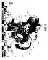
- FIG. 2is a perspective view of a CBCT imaging system having a gantry configuration with housings for detector and source.
- FIG. 3is a perspective view of a CBCT imaging system having a gantry configuration with extendible housings for detector and source.
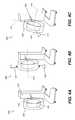
- FIGS. 4A, 4B, and 4Care perspective views that show a CBCT imaging system having a gantry configuration, with various aspects of gantry movement.
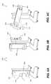
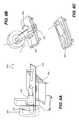
- FIGS. 5A, 5B, 5C, and 5Dare perspective views that show a CBCT imaging system having a rotating arm gantry configuration, with various aspects of gantry movement.
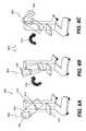
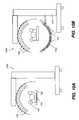
- FIGS. 6A, 6B, and 6Cshow an embodiment for tomosynthesis with a detached detector.
- FIG. 7shows an overhead gantry for a radiation source or detector.
- FIG. 8Ashows an alternate embodiment in which the platform pivots on the bed to allow positioning of the patient.
- FIGS. 8B-8Care perspective views that shows how the pivoting platform positions the patient.
- FIGS. 9A, 9B, and 9Cshow side views of an inflatable mat for patient support.
- FIG. 10Ashows a multi-source system with stationary detector.
- FIG. 10Bshows a multi-source system with an orbiting detector.
- a scanner gantry 206mounts the radiation source 102 and DR detector 104 components for orbital movement about the head of the patient 106 in a direction indicated by the arrow 216 to achieve 180 degrees plus cone angle coverage of the head and neck.
- the scanner gantry 206may be arranged in a number of ways. In one embodiment, shown schematically in FIGS. 2, 3, and 4A-4C , the radiation source 102 and detector 104 orbit the patient 106 within the outer circumference of the scanner gantry 206 .
- the scanner gantry 206may be vertically moved to adjust for the height of the bed or other platform 222 on which the patient 106 lies.
- the support column 212supports the scanner gantry 206 and may include a motorized mechanism to move the scanner gantry 206 vertically 402 , 404 , as shown in FIG. 4B , as well as to tilt the scanner gantry 206 .
- the support column 212may also be attached to a base portion 218 .
- the base portion 218may also be fitted with wheels 302 for easing movement of the CBCT imaging system 200 across a floor.
- Such an assemblymay be referred to herein as a wheeled base portion 218 for the CBCT imaging system 200 .
- the scanner gantry 206may be tilted about an axis 410 which is aligned with element 420 , such as in the direction of the arrow 414 , as shown in FIG.
- the axes 410 , 412may be said to be perpendicular.
- the axis 411may be perpendicular to both axes 410 , 412 , and some amount of rotation about the axis 411 may also be provided.
- the radiation source 102 and detector 104may be attached to extendible arms 303 , 305 ( FIG. 3 ), respectively, so that they may be extended outward or inward, as indicated by the arrows 302 , 304 , with respect to the scanner gantry 206 , to an imaging position further or nearer to the scanner gantry 206 .
- a rotating arm 506supports the radiation source 102 and detector 104 .
- the rotating arm 506may rotate about a central rotation axis 410 during a radiographic imaging scan using a rotating shaft 510 , in the direction indicated by arrow 414 , for example.
- FIG. 5Dshows a side view.
- the rotating arm 506may be vertically adjustable as indicated by the arrows 402 , 404 . In one embodiment ( FIG.
- a variable source-to-image (source-to-detector) distancemay be utilized by moving either the radiation source 102 , detector 104 , or both, toward or away from each other, as indicated by the arrows 504 , 508 , respectively, along support arms 505 , 507 , respectively.
- SIDsource-to-image distance
- the radiation source 102 and detector 104may be attached to a rotating arm 606 and positioned on separate, independently adjustable mounts, to allow independent movement.
- the detector 104may be detached from the rotating arm 606 , for example, and mounted to the support column 212 , for example, beneath the patient 106 .
- the radiation source 102may be moved above the patient's head to desired exposure angles 602 , 603 , 604 by rotating it with respect to the rotating arm 606 . This may be performed while rotating the rotating arm 606 using a rotating support shaft 510 in a direction as indicated by the arrow 614 to a desirable position as shown in the FIGS. 6A-C .
- a radiation source 102 rotation of 90 degreesmay be enabled.
- the radiation source 102may be extended inward or outward from the axis of rotation as shown in FIG. 5C , or may be extended nearer or further from the rotating arm 606 as shown in FIG. 3 .
- the scanner gantry 206may serve as a housing or enclosure for at least a portion of the components that move and connect to the radiation source 102 and the detector 104 .
- the scanner gantry 206may be height adjustable and may rotate about the axis that corresponds to the head of the patient 106 , e.g., a lengthwise body axis.
- Variable angular positioning of the scanner gantry 206enables the patient 106 to be in a reclining or in a vertical position.
- a number of variable SID arrangementsare possible, including a telescoping aim that moves detector 104 and/or radiation source 102 to different distances from the axis of rotation.
- Image processingadapts to different SID and angular ranges.
- the SIDmay be extended to accommodate patient shoulders, or bed dimensions.
- a collimatormay be used to adjust the beam dimensions for each SID change.
- the scanner gantry 206itself may have telescoping sections.
- the scanner gantry 206may support the radiation source 102 or detector 104 and provide movement from above the patient, so that the area around the patient's head is unobstructed.
- An arrangement of the radiation source 102 and detector 104 providing an unobstructed region around the patient's headis shown in FIG. 7 where a scanner gantry 706 is configured to provide a track 702 for movement of the radiation source 102 with respect to a detector 104 .
- a patient's headmay be positioned proximate the detector 104 in the area 707 , for example, while the patient 106 is lying on a bed or other support that is rolled into close proximity to the CBCT imaging system 700 using an embodiment of the wheeled base portion 218 described herein.
- variable patient support platform 802may be provided as part of the CBCT imaging system 800 .
- the variable patient support platform 802may be configured to fit within the bore 204 of the scanner gantry 206 , or the variable patient support platform 802 may include a narrower portion 224 ( FIG. 2 ) at one end of the platform 802 ( 222 ) beneath the head of the patient 106 that fits within the bore 204 .
- the variable patient support platform 802may be detachable from the main structure of the bed 804 or it may be movable, such as being rotatable or pivotable as illustrated in FIGS. 8A-8B and indicated by the arrow 806 in FIG.
- FIG. 8Ashows the variable patient support platform 802 fitted into the bore 204 of the CBCT imaging system 800 .
- the variable patient support platform 802may also be pulled forward from the bed 804 to fit into the bore 204 as indicated by the arrow 808 in FIG. 8B and demonstrated in FIG. 8A .
- These configurations of the CBCT imaging system 800allow the imaging equipment 206 , 218 , to be moved alongside edges of the bed 804 .
- Alignment sensorsmay be provided for proper alignment of the patient 106 and variable patient support platform 802 relative to the radiation source 102 and detector 104 .
- One or more elevation devicesmay be attached to the bed 804 and used for raising or lowering the patient 106 to the proper height for head imaging using the CBCT imaging system 800 .
- FIGS. 9A-9Cillustrate the use of an inflatable mat 902 to support the patient 106 and allow a height adjustment 908 , and movement in the direction 808 , for example, to align with the bore 204 height.
- a variety of cushioning and support deviceswhich may include foam and inflatable devices, for example, may be provided for stabilizing and positioning the patient anatomy such as in the direction 808 for the exam.
- the scanner gantry 206may be coupled to a support column 212 that provides controls for adjustable scanner gantry height, as described herein.
- a collapsible support column 212may enable improved visibility and weight distribution for transport and use of the CBCT imaging system 200 .
- a telescoping arrangement of the support column 212may serve to provide gantry height adjustment.
- the radiation source 102itself may be linear or curvilinear. Multiple radiation sources may be included, to be separately energized, such as sequentially, or energized as a group.
- a radiation source housing 205provides protection for the x-ray tube(s) or other radiation emitter(s) and related equipment.
- the radiation source housing 205may provide a collimator for limiting the beam width and changing or scaling a beam aspect ratio.
- the DR detector 104may acquire images at a rate that is commensurate with energization and angular disposition of the radiation source 102 .
- the detector 104may transmit acquired data to a system processor over a wired or wireless transmission circuit.
- a detector housing 105may provide protection for the digital detector 104 and related equipment, such as support electronics and battery.
- a number of different position encoders and sensorsmay be provided for the radiation source 102 and the detector 104 , as well as for patient head position relative to radiation source and detector paths.
- a number of fiducial markingsmay also be provided to assist in alignment of the patient 106 or of system imaging components. Fiducials on the board, mattress, or bed help to assist alignment.
- a computer or other type of logic processormay be disposed in the support column 212 , and may communicate electronically with a display 214 attached thereto.
- the computermay interact with the image acquisition system components for setup, exposure control, scanning control including control of transport mechanisms, image data acquisition, and image processing and display.
- the processing logicmay be distributed between multiple processors. Thus, for example, some of the image processing functions may be performed by a processor on the digital detector, prior to transmission of the acquired image data to the computer or other host processor.
- the display 214may present an operator interface for use by a radiology technician, such as utilities for entry of operator commands. Operator interface components are in signal communication with the processor.
- the displaymay be a touchscreen display, for example.
- Input hardwaremay include a mouse, joystick, or control console, for example.
- a laser-illuminated positioning systemmay be provided, for displaying guidelines and target markings for patient and equipment positioning.
- a camera with corresponding display screen, such as a remote display,may also serves to help visualize patient positioning.
- a radiation source transport apparatusorbits the radiation source 102 about the subject extremity to be imaged.
- the radiation source 102generally orbits about a central point comprising a central rotation axis, so that the radius may have a fixed value for any CBCT imaging sequence.
- the radius of the orbitmay be adjusted over a range to suit different imaging conditions.
- the coupling arrangement by which the radiation source housing 205 is coupled to the radiation source transport apparatusallows a change to the orbital radius. This change in radius may be accomplished in a number of ways, such as by an adjustable offset from a threaded connector, for example.
- the radiation source transport apparatusis coupled to the detector transport apparatus. This allows the radiation source 102 to face the detector 104 at 180 degrees for imaging over the range of imaging angles, with the patient 106 between the radiation source 102 and the detector 104 .
- One or more motors or other actuatorsmay be used to move both the radiation source 102 and detector 104 at appropriate speed so that they are at the proper positional relationship with respect to the subject at each angle. Rotation of the radiation source 102 and detector 104 may also be manual.
- the radiation source transport apparatusmay be de-coupled from the detector transport apparatus.
- Motion sensingmay be provided, with position encoders on one or more of the axes.
- a variable orbital radiusmay be provided during the scan, according to an alternate embodiment of the present invention. This changes the SID to adjust for bed and shoulder obstruction.
- the starting and ending points of the scan sequencesuch are adjustable and may be displayed to the operator. The starting and/or ending point may be entered as an operator instruction. Alternately, the starting and ending points of the scan sequence may be set by the operator in manually positioning scanner components.
- a detector transport apparatusorbits the digital detector about the subject extremity to be imaged. As with the radiation source, the detector generally orbits about a central point, so that the radius has a fixed value for any CBCT imaging sequence.
- the radius of the detector orbitmay be adjusted over a range to suit different imaging conditions.
- the coupling arrangement by which the detector housing 105 may be coupled to the detector transport apparatusallows a change to the orbital radius. This change in radius may be accomplished in a number of ways, such as by an adjustable offset from a threaded connector that protrudes through a slot in the detector transport mechanism, for example.
- FIG. 10Ashows a multi-source system 1000 , with each radiation source 102 independently energizable.
- the multiple radiation sources 102may be an array of individual radiation sources 102 , a carbon nanotube array, or other array arrangement.
- the detector 104 a and sources 102are stationary, wherein a partial ring of sources 102 is shown.
- FIG. 10Bshows a multi-source system 1050 with an orbiting detector 104 a .
- multiple stationary detectors 104may be provided, with the arrangement around a curved path as shown in FIG. 10B .
- Each detector 104may be paired with one or more radiation sources 102 , so that energizing a particular radiation source 102 causes an image to be obtained by at least one detector 104 .
- the radiation sources 102may be arranged in two dimensions, so that radiation sources 102 are disposed in parallel about a central axis and also orthogonally arranged along the central axis. This pattern enables an axial or spiral scan pattern. Adjustable collimation may also be provided for multi source arrays. The scanning pattern may proceed in any direction, clockwise or counter-clockwise relative to the patient 106 .
- the wheeled base portion 218allows the scanner to be positioned in tight spaces and around various life-support equipment for the patient 106 .
- the wheeled base portion 218may be battery powered and includes controls to regulate speed and other movement characteristics.
- a grid alignment utilitymay be provided.
- the wheeled base portion 218may have a transport drive system comprising a drive handle responsive to operator control for movement and steering, wherein the drive handle may be adjustable for at least one of height and extension.
- Cabling for interconnection of detector and radiation source components as well as for signals and drive energy to control the detector and radiation source transport apparatusmay be routed through the gantry.
- a cable guidance mechanismmay be provided to route cables and tubing to the outside of the scan area.
- Radiation shieldingmay be provided by the gantry and support column Additional shielding may be provided by coverings provided with the system.
- Lead apron(s)may be provided to cover portions of the imaging apparatus once positioned.
- Visual indication of the primary radiation coverage areamay be provided, such as during scanner setup and prior to energizing the radiation source. This facilitates shielding placement, for example.
- Detector and radiation source transport apparatusmay be coupled together for imaging so that they both orbit the subject at the correct speed for image acquisition. Scanning may be executed by moving the scanner components in either direction, with either clockwise or counter-clockwise motion about the subject anatomy. In more general terms, the relative motion of the source and detector with respect to the subject may be in the clockwise or counter-clockwise direction.
- the basic imaging sequencemay be include the following steps:
- a range of different scan patternsmay be used, including patterns for CBCT imaging, for tomography imaging, and for other imaging modalities. Limited-angle scanning for tomography can be with radiation from the front or rear of the patient.
- the scan patternmay be helical. Where multiple sources are provided, the arrangement of the sources enables a range of different scan patterns, based on the spatial distribution of the sources.
- a “dry run” modeis provided that enables the technician to check scanner motion prior to exposure.
- Manual movement of the scanner through the scan pathis provided.
- a slow motion scan movement sequenceis provided. This helps to check that the scanner movement will not interfere with other equipment or be obstructed by the bed or other devices that support the patient.
- Dry run testingmay be assisted by the system, so that manual movement of the scanner gantry may be supported by transport systems for the source and detector.
- An operator interface command for dry run testingplaces the system in a mode wherein hand pressure from the operator may be sensed and the scanning movement may be executed in slow motion as well as stopped at any point in the scan, such as when the operator wants to reposition a tube or wire, for example.
- Imaging softwareincludes volume image reconstruction software for CBCT and for tomosynthesis imaging. Imaging software includes algorithms for detection and suppression of wires, tubing, and other components that would otherwise cause imaging artifacts during volume reconstruction.
- a support in the form of an inverted Tmay be provided for insertion under the patient and support that enables the patient to be urged forward so that the patient's head extends outside the edge of the mattress.
- a preformed bore insertmay be provided to position the patient's head along the axis of rotation of the scanner.
- the insertmay be foam or inflatable.
- Devices for head stabilizationmay be coupled with the scanner arrangement or provided separately. These devices include foam and inflatable cushions, for example.
- Variable SID adjustmentallows for imaging with the patient on a variable size mattress or supporting platform.
- Angular adjustment of the gantry( FIG. 3C ) allows the orbital plane to be adjusted for bed angle.
- Operator instructionsmay be provided for options on positioning and constraining the patient. Based on the exam type, the operator instructions may show the options available for the exam. The operator may set energy levels (kVp) and make other settings and adjustments to exposure-related parameters. The angular range and resolution may be set and adjusted for variable starting and ending points of the scan sequence. The start and end angles may be displayed to the operator.
- the user interfaceallows exam initiation and termination.
- the operator interface screendisplays results of 2-D projection images as they are captured, as well as the 3-D reconstructed image that may be generated.
- Various parameters related to the subjectmay be displayed and monitored during imaging, including heart rate, muscle tension, and other parameters.
- a touchscreen interfacemay be provided. Alternately, an optional keyboard and mouse may be used for command entry. Alerts and warning devices, visible and audible, may be provided to indicate readiness for and commencement of the scan sequence.
- the detector and radiation sourcemay be moved out of imaging position for guiding the patient's anatomy into the apparatus or exiting the imaging apparatus.
- Detents, fiducials, or other guidesmay be provided in order to obtain precise alignment.
- Laser guide linesmay be provided to assist with patient or scanner positioning.
- a calibration sequencemay be provided for periodic recalibration of the detector.
- exemplary methods/apparatusmay use a computer program with stored instructions that perform on image data that may be accessed from an electronic memory.
- a computer program of an embodiment hereinmay be utilized by a suitable, general-purpose computer system, such as a personal computer or workstation.
- a suitable, general-purpose computer systemsuch as a personal computer or workstation.
- many other types of computer systemsmay be used to execute the computer program of described exemplary embodiments, including an arrangement of networked processors, for example.
- the computer program for performing methods of certain exemplary embodiments described hereinmay be stored in a computer readable storage medium.
- This mediummay comprise, for example; magnetic storage media such as a magnetic disk such as a hard drive or removable device or magnetic tape; optical storage media such as an optical disc, optical tape, or machine readable optical encoding; solid state electronic storage devices such as random access memory (RAM), or read only memory (ROM); or any other physical device or medium employed to store a computer program.
- Computer programs for performing exemplary methods of described embodimentsmay also be stored on computer readable storage medium that may be connected to the image processor by way of the internet or other network or communication medium. Those skilled in the art will further readily recognize that the equivalent of such a computer program product may also be constructed in hardware.
- memorymay refer to any type of temporary or more enduring data storage workspace used for storing and operating upon image data and accessible to a computer system, including a database, for example.
- the memorycould be non-volatile, using, for example, a long-term storage medium such as magnetic or optical storage. Alternately, the memory could be of a more volatile nature, using an electronic circuit, such as random-access memory (RAM) that may be used as a temporary buffer or workspace by a microprocessor or other control logic processor device.
- Display datafor example, is typically stored in a temporary storage buffer that may be directly associated with a display device and may be periodically refreshed as needed in order to provide displayed data.
- This temporary storage buffermay also be considered to be a memory, as the term may be used in the present disclosure.
- Memorymay be also used as the data workspace for executing and storing intermediate and final results of calculations and other processing.
- Computer-accessible memorymay be volatile, non-volatile, or a hybrid combination of volatile and non-volatile types.
- exemplary computer program product embodiments hereinmay make use of various image manipulation algorithms and processes that are well known. It will be further understood that exemplary computer program product embodiments herein may embody algorithms and processes not specifically shown or described herein that are useful for implementation. Such algorithms and processes may include conventional utilities that are within the ordinary skill of the image processing arts. Additional aspects of such algorithms and systems, and hardware and/or software for producing and otherwise processing the images or co-operating with the computer program product of the application, are not specifically shown or described herein and may be selected from such algorithms, systems, hardware, components and elements known in the art.
- NDTnon-destructive testing
- CBCT digital radiography systemsAlthough sometimes described herein with respect to CBCT digital radiography systems, embodiments of the application are not intended to be so limited.
- other DR imaging systemsuch as dental DR imaging systems, mobile DR imaging systems or room-based DR imaging systems may utilize method and apparatus embodiments according to the application.
- an exemplary flat panel DR detector/imagermay be capable of both single shot (radiographic) and continuous (fluoroscopic) image acquisition.
- a fan beam CT DR imaging systemmay be used.
- Exemplary DR detectorsmay be classified into the “direct conversion type” one for directly converting the radiation to an electronic signal and the “indirect conversion type” one for converting the radiation to fluorescence to convert the fluorescence to an electronic signal.
- An indirect conversion type radiographic detectorgenerally includes a scintillator for receiving the radiation to generate fluorescence with the strength in accordance with the amount of the radiation.
Landscapes
- Health & Medical Sciences (AREA)
- Life Sciences & Earth Sciences (AREA)
- Engineering & Computer Science (AREA)
- Medical Informatics (AREA)
- Heart & Thoracic Surgery (AREA)
- Animal Behavior & Ethology (AREA)
- Biophysics (AREA)
- Nuclear Medicine, Radiotherapy & Molecular Imaging (AREA)
- Optics & Photonics (AREA)
- Pathology (AREA)
- Radiology & Medical Imaging (AREA)
- Biomedical Technology (AREA)
- Physics & Mathematics (AREA)
- Molecular Biology (AREA)
- Surgery (AREA)
- High Energy & Nuclear Physics (AREA)
- General Health & Medical Sciences (AREA)
- Public Health (AREA)
- Veterinary Medicine (AREA)
- Pulmonology (AREA)
- Theoretical Computer Science (AREA)
- Neurology (AREA)
- Neurosurgery (AREA)
- Dentistry (AREA)
- Oral & Maxillofacial Surgery (AREA)
- Apparatus For Radiation Diagnosis (AREA)
Abstract
Description
- 1. Guide the scanner into position for imaging the head of the patient. This may require repositioning cables and working around life support equipment.
- 2. Position the patient to allow imaging by the scanner. This may require moving the patient so that the patient's head extends past the edge of the hospital bed. Patient movement can be performed in a number of ways, as described in more detail subsequently.
- 3. Provide any necessary shielding to reduce exposure of nearby persons.
- 4. Optionally test the scanner travel path in a “dry run” mode.
- 5. Execute the image exposure sequence.
- 6. Reposition the patient and remove the scanner
Claims (19)
Priority Applications (4)
| Application Number | Priority Date | Filing Date | Title |
|---|---|---|---|
| US14/537,085US9808211B2 (en) | 2013-11-12 | 2014-11-10 | Head and neck imager |
| PCT/US2014/064905WO2015073388A1 (en) | 2013-11-12 | 2014-11-11 | Head and neck imager |
| EP14803308.7AEP3068306A1 (en) | 2013-11-12 | 2014-11-11 | Head and neck imager |
| CN201480061875.0ACN105873516B (en) | 2013-11-12 | 2014-11-11 | Head and neck imager |
Applications Claiming Priority (2)
| Application Number | Priority Date | Filing Date | Title |
|---|---|---|---|
| US201361902819P | 2013-11-12 | 2013-11-12 | |
| US14/537,085US9808211B2 (en) | 2013-11-12 | 2014-11-10 | Head and neck imager |
Publications (2)
| Publication Number | Publication Date |
|---|---|
| US20150131775A1 US20150131775A1 (en) | 2015-05-14 |
| US9808211B2true US9808211B2 (en) | 2017-11-07 |
Family
ID=53043810
Family Applications (1)
| Application Number | Title | Priority Date | Filing Date |
|---|---|---|---|
| US14/537,085Active2035-07-31US9808211B2 (en) | 2013-11-12 | 2014-11-10 | Head and neck imager |
Country Status (4)
| Country | Link |
|---|---|
| US (1) | US9808211B2 (en) |
| EP (1) | EP3068306A1 (en) |
| CN (1) | CN105873516B (en) |
| WO (1) | WO2015073388A1 (en) |
Cited By (6)
| Publication number | Priority date | Publication date | Assignee | Title |
|---|---|---|---|---|
| US20180008217A1 (en)* | 2016-07-08 | 2018-01-11 | Alexander Gemmel | Motion controllers for mobile x-ray devices |
| US20180199901A1 (en)* | 2015-07-16 | 2018-07-19 | Koninklijke Philips N.V. | Device for remote fluoroscopy, nearby fluoroscopy and radiology |
| US11013476B1 (en) | 2020-06-08 | 2021-05-25 | SIMULATE Technologies, LLC | Weightbearing simulation assembly and methods of using the same to image a subject |
| US20220409146A1 (en)* | 2021-06-23 | 2022-12-29 | Carestream Health, Inc. | Stationary x-ray source array for digital tomosynthesis |
| US20230073617A1 (en)* | 2021-09-07 | 2023-03-09 | Canon Medical Systems Corporation | X-ray computed tomography apparatus and state-change control method |
| US12440174B2 (en)* | 2021-09-07 | 2025-10-14 | Canon Medical Systems Corporation | X-ray computed tomography apparatus and state-change control method |
Families Citing this family (18)
| Publication number | Priority date | Publication date | Assignee | Title |
|---|---|---|---|---|
| US9724056B2 (en)* | 2013-11-28 | 2017-08-08 | Toshiba Medical Systems Corporation | Method and system for spectral computed tomography (CT) with inner ring geometry |
| US20160331339A1 (en)* | 2015-05-15 | 2016-11-17 | The Trustees Of Columbia University In The City Of New York | Systems And Methods For Early Detection And Monitoring Of Osteoarthritis |
| CN108882905B (en) | 2016-03-25 | 2022-08-23 | 卡尔斯特里姆保健公司 | CBCT imaging system with curved detector |
| US10888286B2 (en)* | 2017-03-22 | 2021-01-12 | Carestream Health, Inc. | CBCT imaging system with curved detector and curved grid |
| US12279901B2 (en) | 2017-05-03 | 2025-04-22 | 3Dio, Inc. | Three dimensional X-ray imaging system |
| EP3618718A4 (en) | 2017-05-03 | 2020-11-11 | Turner Innovations, LLC | THREE-DIMENSIONAL X-RAY IMAGING SYSTEM |
| CN107714065A (en) | 2017-09-29 | 2018-02-23 | 上海联影医疗科技有限公司 | X-ray imaging equipment |
| US11375934B2 (en)* | 2017-12-01 | 2022-07-05 | Ricoh Company, Ltd. | Biomagnetic measurement apparatus, biological information measurement apparatus, and biomagnetic measurement method |
| EP3705048B1 (en)* | 2019-03-04 | 2021-04-21 | Boscherini, Duccio | A surgical table with an integrated imaging device |
| WO2021102587A1 (en)* | 2019-11-29 | 2021-06-03 | Innovere Medical Inc. | Systems and methods for passive collision control during medical imaging or therapeutic procedures |
| US11771387B2 (en)* | 2020-01-29 | 2023-10-03 | Aixscan Inc. | Fast 3D radiography using multiple pulsed X-ray sources in motion |
| US11918393B2 (en)* | 2020-06-08 | 2024-03-05 | GE Precision Healthcare LLC | Systems and methods for a stationary CT imaging system |
| US11684324B2 (en) | 2020-07-27 | 2023-06-27 | Canon Medical Systems Corporation | Medical image diagnosis apparatus and controlling method |
| CN112006712B (en)* | 2020-08-24 | 2023-04-25 | 南昌大学第一附属医院 | Intelligent cervical vertebra scanning device based on CBCT |
| US11633168B2 (en)* | 2021-04-02 | 2023-04-25 | AIX Scan, Inc. | Fast 3D radiography with multiple pulsed X-ray sources by deflecting tube electron beam using electro-magnetic field |
| JP7612505B2 (en)* | 2021-04-28 | 2025-01-14 | 富士フイルム株式会社 | Medical imaging equipment |
| US20230210484A1 (en)* | 2022-01-05 | 2023-07-06 | X-Sight Incorporated | Sub-system x-ray source module |
| EP4512340A1 (en)* | 2023-08-23 | 2025-02-26 | Siemens Healthineers AG | Gantry for c-shaped ct system |
Citations (61)
| Publication number | Priority date | Publication date | Assignee | Title |
|---|---|---|---|---|
| US3500045A (en) | 1965-09-21 | 1970-03-10 | Generay Gen Radiologica | Tiltable x-ray table supporting an x-ray tube and detector for displacement and rotation in two directions relative to the table |
| US4115696A (en)* | 1977-04-18 | 1978-09-19 | General Electric Company | Computed tomography scanner |
| US5666392A (en) | 1995-09-12 | 1997-09-09 | Siemens Aktiengesellschaft | X-ray diagnostic installation with a positioning apparatus for a radiation emitter and a radiation receiver |
| US5872828A (en)* | 1996-07-23 | 1999-02-16 | The General Hospital Corporation | Tomosynthesis system for breast imaging |
| US6092928A (en)* | 1998-11-12 | 2000-07-25 | Picker International, Inc. | Apparatus and method to determine the relative position of a detector array and an x-ray tube focal spot |
| US6200024B1 (en)* | 1998-11-27 | 2001-03-13 | Picker International, Inc. | Virtual C-arm robotic positioning system for use in radiographic imaging equipment |
| US6222906B1 (en)* | 1998-01-29 | 2001-04-24 | Kabushiki Kaisha Toshiba | X-ray diagnostic apparatus using an X-ray flat panel detector and method for controlling the X-ray diagnostic apparatus |
| US6236708B1 (en)* | 1998-11-25 | 2001-05-22 | Picker International, Inc. | 2D and 3D tomographic X-ray imaging using flat panel detectors |
| US6325537B1 (en)* | 1998-10-16 | 2001-12-04 | Kabushiki Kaisha Toshiba | X-ray diagnosis apparatus |
| US6400791B1 (en)* | 1999-06-23 | 2002-06-04 | Siemens Aktiengesellschaft | CT device for generating tomograms of slices of a subject which are inclined relative to the longitudinal axis of a patient support |
| US6435715B1 (en)* | 1998-11-30 | 2002-08-20 | Siemens Aktiengesellschaft | Radiography device |
| US6461040B1 (en)* | 1998-11-12 | 2002-10-08 | Koninklijke Philips Electronics N.V. | Apparatus and method to correct for position errors in diagnostic imaging |
| US6496558B2 (en)* | 2000-02-22 | 2002-12-17 | Siemens Aktiengesellschaft | X-ray device and medical workplace for diagnostics and surgical interventions in the head and/or jaw of a patient |
| US6580777B1 (en)* | 1999-01-05 | 2003-06-17 | Hitachi Medical Corporation | X-ray CT apparatus |
| US6637056B1 (en)* | 2001-06-01 | 2003-10-28 | Analogic Corporation | Lifting apparatus and method for patient table |
| US6683935B2 (en)* | 2001-09-28 | 2004-01-27 | Bio-Imaging Research, Inc. | Computed tomography with virtual tilt and angulation |
| US6814489B2 (en)* | 2001-11-23 | 2004-11-09 | Ge Medical Systems Global Technology Company, Llc | 3D reconstruction system and method utilizing a variable X-ray source to image distance |
| US6819736B1 (en)* | 2002-02-22 | 2004-11-16 | Siemens Aktiengesellschaft | Computed tomography method and computed tomography apparatus |
| US6831961B1 (en)* | 2001-06-01 | 2004-12-14 | Analogic Corporation | Combined tomography scanners |
| US6882700B2 (en)* | 2002-04-15 | 2005-04-19 | General Electric Company | Tomosynthesis X-ray mammogram system and method with automatic drive system |
| US6999554B2 (en)* | 2003-11-17 | 2006-02-14 | Siemens Aktiengesellschaft | X-ray diagnostic apparatus for mammography examinations |
| US7003070B1 (en)* | 2004-08-03 | 2006-02-21 | William Barry Chen | Upright CT scanner |
| US7016457B1 (en)* | 1998-12-31 | 2006-03-21 | General Electric Company | Multimode imaging system for generating high quality images |
| US7020236B2 (en)* | 2002-05-06 | 2006-03-28 | Koninklijke Philips Electronics N.V. | Cone beam CT scanners with reduced scan length |
| DE102005004502A1 (en) | 2005-01-31 | 2006-08-10 | "Stiftung Caesar" (Center Of Advanced European Studies And Research) | Tomography device with variable imaging geometry |
| US7108421B2 (en)* | 2002-03-19 | 2006-09-19 | Breakaway Imaging, Llc | Systems and methods for imaging large field-of-view objects |
| US7212606B2 (en)* | 2004-09-24 | 2007-05-01 | General Electric Company | Apparatus for radiographic projection tomography |
| US7300204B2 (en)* | 2005-03-03 | 2007-11-27 | Kabushiki Kaisha Toshiba | X-ray diagnostic apparatus |
| US7338207B2 (en)* | 2002-08-21 | 2008-03-04 | Medtronic Navigation, Inc. | Gantry positioning apparatus for X-ray imaging |
| WO2008035828A1 (en) | 2006-09-22 | 2008-03-27 | Ray Co., Ltd. | Dental complex imaging system |
| US7379526B2 (en)* | 2004-11-04 | 2008-05-27 | Ge Medical Systems Global Technology Company, Llc | X-ray CT apparatus and X-ray CT imaging method |
| US7418074B2 (en)* | 2005-03-31 | 2008-08-26 | Siemens Aktiengesellschaft | Computed tomography system with adjustable focal spot-to-detector distance |
| US7453979B2 (en)* | 2006-10-26 | 2008-11-18 | Fujifilm Corporation | Tomographic image obtainment apparatus and method |
| US7515677B2 (en)* | 2006-09-29 | 2009-04-07 | Siemens Aktiengesellschaft | Method for x-ray image recording of a non-centric imaging area using an x-ray imaging system, and x-ray imaging system |
| US7515679B2 (en)* | 2007-06-01 | 2009-04-07 | Qr (Quantitative Radiography) Srl | Method and system for cone beam x-ray source and detector arrangement in computed tomography systems |
| US7591587B2 (en)* | 2006-07-24 | 2009-09-22 | Kabushiki Kaisha Toshiba | Method for controlling X-ray diagnostic apparatus |
| US7623905B2 (en)* | 2005-07-25 | 2009-11-24 | Siemens Aktiengesellschaft | Method for production of computer-tomographic scans during an intervention |
| US20100008474A1 (en) | 2008-07-09 | 2010-01-14 | Oliver Hornung | X-ray system |
| US7697661B2 (en)* | 2006-09-05 | 2010-04-13 | General Electric Company | Method for obtaining a tomosynthesis image |
| US7778388B2 (en)* | 2006-10-31 | 2010-08-17 | Fujifilm Corporation | Radiation tomographic image generation apparatus |
| US7806589B2 (en)* | 2007-09-26 | 2010-10-05 | University Of Pittsburgh | Bi-plane X-ray imaging system |
| US7835490B2 (en)* | 2006-02-01 | 2010-11-16 | Siemens Aktiengesellschaft | Mammography appliance |
| US7837385B2 (en)* | 2006-08-10 | 2010-11-23 | Siemens Aktiengesellschaft | Method for recording X-ray images by means of a robotically controlled C-arm system and recording device for recording X-ray images |
| US7885379B2 (en)* | 2006-02-03 | 2011-02-08 | Siemens Aktiengesellschaft | Positioning device for a mammography unit |
| US8031834B2 (en)* | 2008-10-06 | 2011-10-04 | Siemens Aktiengesellschaft | Tomosynthesis apparatus and method to operate a tomosynthesis apparatus |
| US8300762B2 (en)* | 2007-11-16 | 2012-10-30 | J. Morita Manufacturing Corporation | X-ray CT imaging apparatus |
| US8320517B2 (en)* | 2009-10-12 | 2012-11-27 | Siemens Aktiengesellschaft | X-ray system and method for the generation of a scan path |
| US8363050B2 (en)* | 2006-05-24 | 2013-01-29 | Siemens Aktiengesellschaft | Method and device for producing a tomosynthetic 3D X-ray image |
| EP2599439A1 (en) | 2011-11-30 | 2013-06-05 | J. Morita Manufacturing Corporation | X-ray CT imaging device |
| US8475040B2 (en)* | 2009-03-04 | 2013-07-02 | Socledad Espa{umlaut over (n)}ola de Electromedicina y Calidad, S.A. | X-ray apparatus for tomosynthesis |
| US8553837B2 (en)* | 2010-08-31 | 2013-10-08 | Siemens Aktiengesellschaft | Method and tomosynthesis apparatus to show a predetermined volume segment of an examination subject |
| US8571172B2 (en)* | 2008-04-14 | 2013-10-29 | Arineta Ltd. | CT cone beam scanner |
| US8662749B2 (en)* | 2010-08-12 | 2014-03-04 | Omid Ebrahimi Kia | Digital radiographic device having a linear scanner |
| US8693621B2 (en)* | 2008-05-01 | 2014-04-08 | Koninklijke Philips N. V. | Source and/or detector positioning system |
| US8903039B2 (en)* | 2012-09-28 | 2014-12-02 | Fujifilm Corporation | Tomographic image generation device and method |
| US8913713B2 (en)* | 2012-09-28 | 2014-12-16 | Fujifilm Corporation | Radiographic image generation device and method |
| US9144406B2 (en)* | 2012-10-01 | 2015-09-29 | Siemens Aktiengesellschaft | Configuration and method for tomosynthetic fluoroscopy |
| US9282942B2 (en)* | 2012-07-11 | 2016-03-15 | Siemens Aktiengesellschaft | Device and method for a diagnostic apparatus |
| US9298194B2 (en)* | 2010-11-30 | 2016-03-29 | Samsung Electronics Co., Ltd. | Method to control medical equipment |
| US9675277B2 (en)* | 2013-09-30 | 2017-06-13 | Fujifilm Corporation | Breast thickness measurement device and breast thickness measurement method |
| US9717467B2 (en)* | 2012-10-08 | 2017-08-01 | Carestream Health, Inc. | Extremity imaging apparatus for cone beam computed tomography |
Family Cites Families (8)
| Publication number | Priority date | Publication date | Assignee | Title |
|---|---|---|---|---|
| WO2006119420A1 (en)* | 2005-05-02 | 2006-11-09 | Xoran Technologies, Inc. | Ct scanner for lower extremities |
| JP2011502567A (en)* | 2007-11-06 | 2011-01-27 | コーニンクレッカ フィリップス エレクトロニクス エヌ ヴィ | Nuclear medicine SPECT-CT apparatus with integrated asymmetric flat panel cone beam CT and SPECT system |
| US8210745B2 (en) | 2009-05-04 | 2012-07-03 | John Yorkston | Extremity imaging apparatus for cone beam computed tomography |
| US8348506B2 (en)* | 2009-05-04 | 2013-01-08 | John Yorkston | Extremity imaging apparatus for cone beam computed tomography |
| DE102009041172B4 (en)* | 2009-09-11 | 2018-03-29 | Siemens Healthcare Gmbh | Device for flexible positioning of radiation source and radiation detector for medical imaging |
| US8568028B2 (en) | 2010-04-13 | 2013-10-29 | Carestream Health, Inc. | Mobile radiography unit having collapsible support column |
| US8672543B2 (en) | 2010-04-13 | 2014-03-18 | Carestream Health, Inc. | Counterweight for mobile x-ray device |
| FI125528B (en)* | 2010-04-29 | 2015-11-13 | Planmed Oy | Medical X-ray imaging equipment |
- 2014
- 2014-11-10USUS14/537,085patent/US9808211B2/enactiveActive
- 2014-11-11CNCN201480061875.0Apatent/CN105873516B/enactiveActive
- 2014-11-11EPEP14803308.7Apatent/EP3068306A1/ennot_activeWithdrawn
- 2014-11-11WOPCT/US2014/064905patent/WO2015073388A1/enactiveApplication Filing
Patent Citations (64)
| Publication number | Priority date | Publication date | Assignee | Title |
|---|---|---|---|---|
| US3500045A (en) | 1965-09-21 | 1970-03-10 | Generay Gen Radiologica | Tiltable x-ray table supporting an x-ray tube and detector for displacement and rotation in two directions relative to the table |
| US4115696A (en)* | 1977-04-18 | 1978-09-19 | General Electric Company | Computed tomography scanner |
| US5666392A (en) | 1995-09-12 | 1997-09-09 | Siemens Aktiengesellschaft | X-ray diagnostic installation with a positioning apparatus for a radiation emitter and a radiation receiver |
| US5872828A (en)* | 1996-07-23 | 1999-02-16 | The General Hospital Corporation | Tomosynthesis system for breast imaging |
| US6222906B1 (en)* | 1998-01-29 | 2001-04-24 | Kabushiki Kaisha Toshiba | X-ray diagnostic apparatus using an X-ray flat panel detector and method for controlling the X-ray diagnostic apparatus |
| US6325537B1 (en)* | 1998-10-16 | 2001-12-04 | Kabushiki Kaisha Toshiba | X-ray diagnosis apparatus |
| US6461040B1 (en)* | 1998-11-12 | 2002-10-08 | Koninklijke Philips Electronics N.V. | Apparatus and method to correct for position errors in diagnostic imaging |
| US6092928A (en)* | 1998-11-12 | 2000-07-25 | Picker International, Inc. | Apparatus and method to determine the relative position of a detector array and an x-ray tube focal spot |
| US6236708B1 (en)* | 1998-11-25 | 2001-05-22 | Picker International, Inc. | 2D and 3D tomographic X-ray imaging using flat panel detectors |
| US6200024B1 (en)* | 1998-11-27 | 2001-03-13 | Picker International, Inc. | Virtual C-arm robotic positioning system for use in radiographic imaging equipment |
| US6435715B1 (en)* | 1998-11-30 | 2002-08-20 | Siemens Aktiengesellschaft | Radiography device |
| US7016457B1 (en)* | 1998-12-31 | 2006-03-21 | General Electric Company | Multimode imaging system for generating high quality images |
| US6580777B1 (en)* | 1999-01-05 | 2003-06-17 | Hitachi Medical Corporation | X-ray CT apparatus |
| US6400791B1 (en)* | 1999-06-23 | 2002-06-04 | Siemens Aktiengesellschaft | CT device for generating tomograms of slices of a subject which are inclined relative to the longitudinal axis of a patient support |
| US6496558B2 (en)* | 2000-02-22 | 2002-12-17 | Siemens Aktiengesellschaft | X-ray device and medical workplace for diagnostics and surgical interventions in the head and/or jaw of a patient |
| US6637056B1 (en)* | 2001-06-01 | 2003-10-28 | Analogic Corporation | Lifting apparatus and method for patient table |
| US6831961B1 (en)* | 2001-06-01 | 2004-12-14 | Analogic Corporation | Combined tomography scanners |
| US6683935B2 (en)* | 2001-09-28 | 2004-01-27 | Bio-Imaging Research, Inc. | Computed tomography with virtual tilt and angulation |
| US6814489B2 (en)* | 2001-11-23 | 2004-11-09 | Ge Medical Systems Global Technology Company, Llc | 3D reconstruction system and method utilizing a variable X-ray source to image distance |
| US6819736B1 (en)* | 2002-02-22 | 2004-11-16 | Siemens Aktiengesellschaft | Computed tomography method and computed tomography apparatus |
| US7108421B2 (en)* | 2002-03-19 | 2006-09-19 | Breakaway Imaging, Llc | Systems and methods for imaging large field-of-view objects |
| US6882700B2 (en)* | 2002-04-15 | 2005-04-19 | General Electric Company | Tomosynthesis X-ray mammogram system and method with automatic drive system |
| US7020236B2 (en)* | 2002-05-06 | 2006-03-28 | Koninklijke Philips Electronics N.V. | Cone beam CT scanners with reduced scan length |
| US7338207B2 (en)* | 2002-08-21 | 2008-03-04 | Medtronic Navigation, Inc. | Gantry positioning apparatus for X-ray imaging |
| US6999554B2 (en)* | 2003-11-17 | 2006-02-14 | Siemens Aktiengesellschaft | X-ray diagnostic apparatus for mammography examinations |
| US7003070B1 (en)* | 2004-08-03 | 2006-02-21 | William Barry Chen | Upright CT scanner |
| US7212606B2 (en)* | 2004-09-24 | 2007-05-01 | General Electric Company | Apparatus for radiographic projection tomography |
| US7379526B2 (en)* | 2004-11-04 | 2008-05-27 | Ge Medical Systems Global Technology Company, Llc | X-ray CT apparatus and X-ray CT imaging method |
| DE102005004502A1 (en) | 2005-01-31 | 2006-08-10 | "Stiftung Caesar" (Center Of Advanced European Studies And Research) | Tomography device with variable imaging geometry |
| US20080310584A1 (en) | 2005-01-31 | 2008-12-18 | Sirona Dental Systems Gmbh | Tomography Equipment Comprising a Variable Reproduction Geometry |
| US7300204B2 (en)* | 2005-03-03 | 2007-11-27 | Kabushiki Kaisha Toshiba | X-ray diagnostic apparatus |
| US7418074B2 (en)* | 2005-03-31 | 2008-08-26 | Siemens Aktiengesellschaft | Computed tomography system with adjustable focal spot-to-detector distance |
| US7623905B2 (en)* | 2005-07-25 | 2009-11-24 | Siemens Aktiengesellschaft | Method for production of computer-tomographic scans during an intervention |
| US7835490B2 (en)* | 2006-02-01 | 2010-11-16 | Siemens Aktiengesellschaft | Mammography appliance |
| US7885379B2 (en)* | 2006-02-03 | 2011-02-08 | Siemens Aktiengesellschaft | Positioning device for a mammography unit |
| US8363050B2 (en)* | 2006-05-24 | 2013-01-29 | Siemens Aktiengesellschaft | Method and device for producing a tomosynthetic 3D X-ray image |
| US7591587B2 (en)* | 2006-07-24 | 2009-09-22 | Kabushiki Kaisha Toshiba | Method for controlling X-ray diagnostic apparatus |
| US7837385B2 (en)* | 2006-08-10 | 2010-11-23 | Siemens Aktiengesellschaft | Method for recording X-ray images by means of a robotically controlled C-arm system and recording device for recording X-ray images |
| US7697661B2 (en)* | 2006-09-05 | 2010-04-13 | General Electric Company | Method for obtaining a tomosynthesis image |
| WO2008035828A1 (en) | 2006-09-22 | 2008-03-27 | Ray Co., Ltd. | Dental complex imaging system |
| US8005186B2 (en)* | 2006-09-22 | 2011-08-23 | Ray Co., Ltd. | Complex imaging system for dental |
| US7515677B2 (en)* | 2006-09-29 | 2009-04-07 | Siemens Aktiengesellschaft | Method for x-ray image recording of a non-centric imaging area using an x-ray imaging system, and x-ray imaging system |
| US7453979B2 (en)* | 2006-10-26 | 2008-11-18 | Fujifilm Corporation | Tomographic image obtainment apparatus and method |
| US7778388B2 (en)* | 2006-10-31 | 2010-08-17 | Fujifilm Corporation | Radiation tomographic image generation apparatus |
| US7515679B2 (en)* | 2007-06-01 | 2009-04-07 | Qr (Quantitative Radiography) Srl | Method and system for cone beam x-ray source and detector arrangement in computed tomography systems |
| US7806589B2 (en)* | 2007-09-26 | 2010-10-05 | University Of Pittsburgh | Bi-plane X-ray imaging system |
| US8300762B2 (en)* | 2007-11-16 | 2012-10-30 | J. Morita Manufacturing Corporation | X-ray CT imaging apparatus |
| US8571172B2 (en)* | 2008-04-14 | 2013-10-29 | Arineta Ltd. | CT cone beam scanner |
| US8693621B2 (en)* | 2008-05-01 | 2014-04-08 | Koninklijke Philips N. V. | Source and/or detector positioning system |
| US7988357B2 (en)* | 2008-07-09 | 2011-08-02 | Siemens Aktiengesellschaft | X-ray system |
| US20100008474A1 (en) | 2008-07-09 | 2010-01-14 | Oliver Hornung | X-ray system |
| US8031834B2 (en)* | 2008-10-06 | 2011-10-04 | Siemens Aktiengesellschaft | Tomosynthesis apparatus and method to operate a tomosynthesis apparatus |
| US8475040B2 (en)* | 2009-03-04 | 2013-07-02 | Socledad Espa{umlaut over (n)}ola de Electromedicina y Calidad, S.A. | X-ray apparatus for tomosynthesis |
| US8320517B2 (en)* | 2009-10-12 | 2012-11-27 | Siemens Aktiengesellschaft | X-ray system and method for the generation of a scan path |
| US8662749B2 (en)* | 2010-08-12 | 2014-03-04 | Omid Ebrahimi Kia | Digital radiographic device having a linear scanner |
| US8553837B2 (en)* | 2010-08-31 | 2013-10-08 | Siemens Aktiengesellschaft | Method and tomosynthesis apparatus to show a predetermined volume segment of an examination subject |
| US9298194B2 (en)* | 2010-11-30 | 2016-03-29 | Samsung Electronics Co., Ltd. | Method to control medical equipment |
| EP2599439A1 (en) | 2011-11-30 | 2013-06-05 | J. Morita Manufacturing Corporation | X-ray CT imaging device |
| US9282942B2 (en)* | 2012-07-11 | 2016-03-15 | Siemens Aktiengesellschaft | Device and method for a diagnostic apparatus |
| US8913713B2 (en)* | 2012-09-28 | 2014-12-16 | Fujifilm Corporation | Radiographic image generation device and method |
| US8903039B2 (en)* | 2012-09-28 | 2014-12-02 | Fujifilm Corporation | Tomographic image generation device and method |
| US9144406B2 (en)* | 2012-10-01 | 2015-09-29 | Siemens Aktiengesellschaft | Configuration and method for tomosynthetic fluoroscopy |
| US9717467B2 (en)* | 2012-10-08 | 2017-08-01 | Carestream Health, Inc. | Extremity imaging apparatus for cone beam computed tomography |
| US9675277B2 (en)* | 2013-09-30 | 2017-06-13 | Fujifilm Corporation | Breast thickness measurement device and breast thickness measurement method |
Non-Patent Citations (1)
| Title |
|---|
| International Search Report dated May 6, 2015 for International Application No. PCT/US2014/064905, 3 pages. |
Cited By (9)
| Publication number | Priority date | Publication date | Assignee | Title |
|---|---|---|---|---|
| US20180199901A1 (en)* | 2015-07-16 | 2018-07-19 | Koninklijke Philips N.V. | Device for remote fluoroscopy, nearby fluoroscopy and radiology |
| US10993685B2 (en)* | 2015-07-16 | 2021-05-04 | Koninklijke Philips N.V. | Device for remote fluoroscopy, nearby fluoroscopy and radiology |
| US20180008217A1 (en)* | 2016-07-08 | 2018-01-11 | Alexander Gemmel | Motion controllers for mobile x-ray devices |
| US10751010B2 (en)* | 2016-07-08 | 2020-08-25 | Siemens Healthcare Gmbh | Motion controllers for mobile X-ray devices |
| US11013476B1 (en) | 2020-06-08 | 2021-05-25 | SIMULATE Technologies, LLC | Weightbearing simulation assembly and methods of using the same to image a subject |
| US11317876B2 (en) | 2020-06-08 | 2022-05-03 | SIMULATE Technologies, LLC | Weightbearing simulation assembly and methods of using the same to image a subject |
| US20220409146A1 (en)* | 2021-06-23 | 2022-12-29 | Carestream Health, Inc. | Stationary x-ray source array for digital tomosynthesis |
| US20230073617A1 (en)* | 2021-09-07 | 2023-03-09 | Canon Medical Systems Corporation | X-ray computed tomography apparatus and state-change control method |
| US12440174B2 (en)* | 2021-09-07 | 2025-10-14 | Canon Medical Systems Corporation | X-ray computed tomography apparatus and state-change control method |
Also Published As
| Publication number | Publication date |
|---|---|
| WO2015073388A4 (en) | 2015-07-16 |
| EP3068306A1 (en) | 2016-09-21 |
| CN105873516A (en) | 2016-08-17 |
| WO2015073388A1 (en) | 2015-05-21 |
| US20150131775A1 (en) | 2015-05-14 |
| CN105873516B (en) | 2020-07-10 |
Similar Documents
| Publication | Publication Date | Title |
|---|---|---|
| US9808211B2 (en) | Head and neck imager | |
| US11229409B2 (en) | Mobile imaging ring system | |
| US10463325B2 (en) | Mobile radiographic apparatus/methods with tomosynthesis capability | |
| EP3646793B1 (en) | Mobile imaging ring system | |
| EP2903522B1 (en) | Extremity imaging apparatus for cone beam computed tomography | |
| EP2865335B1 (en) | Scanning system for three-dimensional imaging | |
| CN1585621B (en) | Three-dimensional reconstruction system and method using variable X-ray source-to-image distance | |
| JP5372461B2 (en) | Portable tomography diagnostic system with an open gantry | |
| EP2502561B1 (en) | Arc-shaped medical imaging equipment | |
| US10548540B2 (en) | Extremity imaging apparatus for cone beam computed tomography | |
| US20150320375A1 (en) | Device and method for radiographic and nuclear imaging of an object | |
| JP2023554170A (en) | Multi-axis medical imaging | |
| JP2021192853A (en) | Subject conveyance tool for x-ray computer tomographic apparatus | |
| US10307123B2 (en) | Tomosynthesis views from cone beam computed tomography data | |
| JP7510948B2 (en) | Operating table with integrated imaging device | |
| US20250248672A1 (en) | Friction wheel motorization for a floor mounted medical imaging device |
Legal Events
| Date | Code | Title | Description |
|---|---|---|---|
| AS | Assignment | Owner name:CARESTREAM HEALTH, INC., NEW YORK Free format text:ASSIGNMENT OF ASSIGNORS INTEREST;ASSIGNORS:YORKSTON, JOHN;WENDLANDT, WILLIAM C.;NEWMAN, PETER A.;AND OTHERS;SIGNING DATES FROM 20150112 TO 20150127;REEL/FRAME:034831/0892 | |
| STCF | Information on status: patent grant | Free format text:PATENTED CASE | |
| CC | Certificate of correction | ||
| AS | Assignment | Owner name:CREDIT SUISSE AG, CAYMAN ISLANDS BRANCH, NEW YORK Free format text:SECURITY INTEREST;ASSIGNORS:CARESTREAM HEALTH, INC.;CARESTREAM HEALTH HOLDINGS, INC.;CARESTREAM HEALTH CANADA HOLDINGS, INC.;AND OTHERS;REEL/FRAME:048077/0529 Effective date:20190114 Owner name:CREDIT SUISSE AG, CAYMAN ISLANDS BRANCH, NEW YORK Free format text:SECURITY INTEREST;ASSIGNORS:CARESTREAM HEALTH, INC.;CARESTREAM HEALTH HOLDINGS, INC.;CARESTREAM HEALTH CANADA HOLDINGS, INC.;AND OTHERS;REEL/FRAME:048077/0587 Effective date:20190114 | |
| MAFP | Maintenance fee payment | Free format text:PAYMENT OF MAINTENANCE FEE, 4TH YEAR, LARGE ENTITY (ORIGINAL EVENT CODE: M1551); ENTITY STATUS OF PATENT OWNER: LARGE ENTITY Year of fee payment:4 | |
| AS | Assignment | Owner name:JPMORGAN CHASE BANK, N.A., ILLINOIS Free format text:GRANT OF SECURITY INTEREST IN PATENT RIGHTS - TL;ASSIGNOR:CARESTREAM HEALTH, INC.;REEL/FRAME:061579/0341 Effective date:20220930 Owner name:JPMORGAN CHASE BANK, N.A., ILLINOIS Free format text:GRANT OF SECURITY INTEREST IN PATENT RIGHTS - ABL;ASSIGNOR:CARESTREAM HEALTH, INC.;REEL/FRAME:061579/0301 Effective date:20220930 | |
| AS | Assignment | Owner name:CARESTREAM HEALTH WORLD HOLDINGS LLC, NEW YORK Free format text:RELEASE OF SECURITY INTEREST IN INTELLECTUAL PROPERTY (FIRST LIEN);ASSIGNOR:CREDIT SUISSE AG, CAYMAN ISLANDS BRANCH;REEL/FRAME:061683/0529 Effective date:20220930 Owner name:CARESTREAM HEALTH ACQUISITION, LLC, NEW YORK Free format text:RELEASE OF SECURITY INTEREST IN INTELLECTUAL PROPERTY (FIRST LIEN);ASSIGNOR:CREDIT SUISSE AG, CAYMAN ISLANDS BRANCH;REEL/FRAME:061683/0529 Effective date:20220930 Owner name:CARESTREAM HEALTH CANADA HOLDINGS, INC., NEW YORK Free format text:RELEASE OF SECURITY INTEREST IN INTELLECTUAL PROPERTY (FIRST LIEN);ASSIGNOR:CREDIT SUISSE AG, CAYMAN ISLANDS BRANCH;REEL/FRAME:061683/0529 Effective date:20220930 Owner name:CARESTREAM HEALTH HOLDINGS, INC., NEW YORK Free format text:RELEASE OF SECURITY INTEREST IN INTELLECTUAL PROPERTY (FIRST LIEN);ASSIGNOR:CREDIT SUISSE AG, CAYMAN ISLANDS BRANCH;REEL/FRAME:061683/0529 Effective date:20220930 Owner name:CARESTREAM HEALTH, INC., NEW YORK Free format text:RELEASE OF SECURITY INTEREST IN INTELLECTUAL PROPERTY (FIRST LIEN);ASSIGNOR:CREDIT SUISSE AG, CAYMAN ISLANDS BRANCH;REEL/FRAME:061683/0529 Effective date:20220930 Owner name:CARESTREAM HEALTH WORLD HOLDINGS LLC, NEW YORK Free format text:RELEASE OF SECURITY INTEREST IN INTELLECTUAL PROPERTY (SECOND LIEN);ASSIGNOR:CREDIT SUISSE AG, CAYMAN ISLANDS BRANCH;REEL/FRAME:061683/0681 Effective date:20220930 Owner name:CARESTREAM HEALTH ACQUISITION, LLC, NEW YORK Free format text:RELEASE OF SECURITY INTEREST IN INTELLECTUAL PROPERTY (SECOND LIEN);ASSIGNOR:CREDIT SUISSE AG, CAYMAN ISLANDS BRANCH;REEL/FRAME:061683/0681 Effective date:20220930 Owner name:CARESTREAM HEALTH CANADA HOLDINGS, INC., NEW YORK Free format text:RELEASE OF SECURITY INTEREST IN INTELLECTUAL PROPERTY (SECOND LIEN);ASSIGNOR:CREDIT SUISSE AG, CAYMAN ISLANDS BRANCH;REEL/FRAME:061683/0681 Effective date:20220930 Owner name:CARESTREAM HEALTH HOLDINGS, INC., NEW YORK Free format text:RELEASE OF SECURITY INTEREST IN INTELLECTUAL PROPERTY (SECOND LIEN);ASSIGNOR:CREDIT SUISSE AG, CAYMAN ISLANDS BRANCH;REEL/FRAME:061683/0681 Effective date:20220930 Owner name:CARESTREAM HEALTH, INC., NEW YORK Free format text:RELEASE OF SECURITY INTEREST IN INTELLECTUAL PROPERTY (SECOND LIEN);ASSIGNOR:CREDIT SUISSE AG, CAYMAN ISLANDS BRANCH;REEL/FRAME:061683/0681 Effective date:20220930 | |
| FEPP | Fee payment procedure | Free format text:MAINTENANCE FEE REMINDER MAILED (ORIGINAL EVENT CODE: REM.); ENTITY STATUS OF PATENT OWNER: LARGE ENTITY |