US9807876B2 - Electronic reading device - Google Patents
Electronic reading deviceDownload PDFInfo
- Publication number
- US9807876B2 US9807876B2US14/403,157US201314403157AUS9807876B2US 9807876 B2US9807876 B2US 9807876B2US 201314403157 AUS201314403157 AUS 201314403157AUS 9807876 B2US9807876 B2US 9807876B2
- Authority
- US
- United States
- Prior art keywords
- display
- reading device
- electronic reading
- backplane
- handle
- Prior art date
- Legal status (The legal status is an assumption and is not a legal conclusion. Google has not performed a legal analysis and makes no representation as to the accuracy of the status listed.)
- Active, expires
Links
Images


Classifications
- H—ELECTRICITY
- H05—ELECTRIC TECHNIQUES NOT OTHERWISE PROVIDED FOR
- H05K—PRINTED CIRCUITS; CASINGS OR CONSTRUCTIONAL DETAILS OF ELECTRIC APPARATUS; MANUFACTURE OF ASSEMBLAGES OF ELECTRICAL COMPONENTS
- H05K1/00—Printed circuits
- H05K1/02—Details
- H05K1/0277—Bendability or stretchability details
- H05K1/028—Bending or folding regions of flexible printed circuits
- G—PHYSICS
- G06—COMPUTING OR CALCULATING; COUNTING
- G06F—ELECTRIC DIGITAL DATA PROCESSING
- G06F1/00—Details not covered by groups G06F3/00 - G06F13/00 and G06F21/00
- G06F1/16—Constructional details or arrangements
- G06F1/1613—Constructional details or arrangements for portable computers
- G06F1/1633—Constructional details or arrangements of portable computers not specific to the type of enclosures covered by groups G06F1/1615 - G06F1/1626
- G06F1/1637—Details related to the display arrangement, including those related to the mounting of the display in the housing
- G06F1/1652—Details related to the display arrangement, including those related to the mounting of the display in the housing the display being flexible, e.g. mimicking a sheet of paper, or rollable
- G—PHYSICS
- G06—COMPUTING OR CALCULATING; COUNTING
- G06F—ELECTRIC DIGITAL DATA PROCESSING
- G06F15/00—Digital computers in general; Data processing equipment in general
- G06F15/02—Digital computers in general; Data processing equipment in general manually operated with input through keyboard and computation using a built-in program, e.g. pocket calculators
- G06F15/025—Digital computers in general; Data processing equipment in general manually operated with input through keyboard and computation using a built-in program, e.g. pocket calculators adapted to a specific application
- G06F15/0291—Digital computers in general; Data processing equipment in general manually operated with input through keyboard and computation using a built-in program, e.g. pocket calculators adapted to a specific application for reading, e.g. e-books
Definitions
- This inventionrelates to improvements in flexible electronic reading devices (‘E-readers’).
- a flexible electronic reading devicecomprising a display part and a handle, wherein said display part comprises: a display backplane on a flexible substrate; and a display mounted over said display backplane; wherein said handle is located at one edge of said display backplane and contains display interface electronics for said display; and wherein said display part of said electronic reading device comprises a unitary, continuous structure lacking a separate housing.
- the combination of the display and backplaneare integrally formed in the sense that that they constitute a continuous, one-piece structure from which the various components cannot be non-destructively separated. There is no separate housing for the display and backbone (although there is a handle along one edge).
- the combination of the display and backplanethemselves provide sufficient stiffness for the device to be self-supporting when held by the handle and essentially the entire device is fabricated on the flexible, plastic substrate of the display backplane. This is, in embodiments, extended beyond the border of the display on at least three sides and used to mount the display interface electronics, using chip-on-plastic technology, and to run the tracks to the display drive electrodes around the edges of the display. Thus in embodiments there is no internal or external stiffening frame for the device and no rigid front panel (although there may be a thin, for example less 100 ⁇ m, protective front layer over the display).
- the display interface electronicsincludes a plurality of pixel driver chips, which are mounted in the handle, preferably on an extension of the plastic substrate.
- theseinclude at least one gate driver chip and at least two source/drain driver chips, one of the source/drain driver chips driving a set of data lines extending from each edge of the display (in a direction generally parallel to the handle).
- a similar techniquemay be employed to connect to either end of the line of a touch sensing track.
- ITOindium tin oxide
- the lateral extension of the plastic substrate beyond the display edgeis concealed by a border of the electronic reading device, which may comprise an opaque region around the border of the display behind the transparent front protective layer (except where a handle is located).
- tracks to the display drive electrodes around the edges of the displaymay be run behind the display area and the display may be substantially borderless.
- a rechargeable battery for the displayis located within the handle, which because the remainder of the display is light, facilitates one-handed user operation. More particularly in such embodiments the centre of mass of the device may then be located within a lower part of the device, at a distance of no greater than 50%, 33%, 20%, 15% or 10% from the lower end of the device. Optionally the centre of mass of the device may be located substantially adjacent a user control in the handle. Such an arrangement further facilitates one-handed user operation.
- the batterymay comprise a thin-film flexible battery such as a polymer battery, and this may extend over a majority, optionally substantially all the rear surface of the device. In this way a relatively large capacity battery may be ‘concealed’ as part of the device.
- the deviceincludes a flexible printed circuit board (PCB) behind the display backplane. Then components on the PCB may be laterally arranged over a first region behind the backplane surface and the flexible battery may be located in a second, non-overlapping region.
- the deviceincludes an inductive loop to receive power for charging the rechargeable battery; this may extend around the border of the device, for example concealed by the opaque border region.
- the displaymay be monochrome or colour.
- the displaymay be an electrophoretic display or an electrofluidic display; in some preferred implementations the display is a colour electrofluidic display.
- the displayincludes a touch-screen layer on a front surface, for example to operate with a stylus or a finger; this may be projected capacitance touch sensing layer or an inductive stylus sensing layer.
- the touch sensing/screen layeris laminated to the front of the display; optionally, but not necessarily, a thin transparent protective film may be provided over the front surface, for example having a thickness less than 0.5 mm, 0.3 mm, 0.2 mm or 0.1 mm.
- the touch-screenis combined with the protective film in a single layer.
- embodiments of the deviceinclude a handle along one edge, this is not essential, and a self-supporting device may be fabricated as a unitary structure.
- the inventionprovides a flexible electronic reading device, the device comprising: a display backplane on a flexible substrate; a display mounted over said display backplane; and display interface electronics for said display, coupled to said display backplane; wherein said display backplane comprises active matrix pixel driver circuitry on a plastic substrate; wherein said plastic substrate extends beyond a border of said display; and wherein at least a portion of said display interface electronics is fabricated on said plastic substrate.
- the plastic substrateextends beyond the border (active area) of said display on one or more sides, and one or more pixel driver chips are mounted on these extended sides of the plastic substrate using chip-on-plastic technology (although other embodiments lack such a border).
- the plastic substrateextends beyond the border of the display on four sides.
- a flexible printed circuit board(PCB) is joined by adhesive to the backplane and the backplane is connected to the PCB by vias which run through to a display side of the backplane. The vias connect to anisotropic conductive film located in the adhesive layer.
- a rear surface of the deviceis substantially completely flat up to one, three, or all four edges of the device.
- a hinged displayfor example comprising at least one hinge running in parallel to the handle to enable one portion of the display to be folded behind another.
- the unfolded displaymay have substantially an A4 or similar size, with the handle at the bottom.
- the top half of the displaymay be folded behind the lower half of the display to provide an approximately A5 size display;
- thismay then be held in portrait mode with the handle at the left or the right.
- the orientation of the devicemay be detected automatically, for example by means of an accelerometer or the like.
- the one or more hingesmay run perpendicular to a handle along a bottom edge of the display and one or more flaps of the display may fold along a vertical line.
- the handlemay also be foldable (or may be shorter than the full width of the display, so that it does not run across a hinge “break”).
- the displaymay be Z-foldable, that is having one mountain fold and one valley fold so that, when folded, one part of the display is located between two adjacent regions of the display. This may be implemented, for example, by providing three display screen hingedly connected to one another.
- the displayincorporates a hinge
- thiscan conveniently be combined with embodiments in which electrode lines running perpendicular to the hinge direction are broken across a line of the hinge and driven from opposite edges of the display, as previously described.
- Either the gate or the drain/source linesmay be broken but since the drain/source lines carry greater current in embodiments these are driven from either edge of the display, for example by separate driver chips.
- one set of drain/source linesmay run upwards between the handle and the hinge and a second set of drain/source lines may run downwards from an upper edge of the display towards the hinge, the extended border of the flexible substrate being employed to run tracks around the edge of the display to drive the upper set of drain/source lines from the top.
- the display hingewill hinge the flexible border of the substrate carrying the tracks as well as the display itself, it is relatively straightforward to provide a set of jumpers, for example on a flexible PCB, to maintain an electrical connection when the display unit Is in its hinged state.
- these tracks at the border of the displaymay simply be broken when the display is in its hinged configuration since, at that point, the hinged away portion of the display is not needed.
- a set of contactsmay be provided such that when adjacent portions of the flexible substrate are hinged flat to define the full sized display. Contacts on the track of one portion of the display may abut against corresponding contacts on the second portion to make the electrical connection.
- alternative approachesmay also be employed.
- the display interface electronicsalso includes electronics for a wireless link to a second electronic device.
- a devicemay be, for example, a laptop or desktop computer, a PDA (personal digital assistant), a mobile phone, in particular a Smartphone, or other such devices.
- the wireless interfacemay be a radio frequency interface, for example a WiFi or BluetoothTM interface or an optical, for example infra-red, interface.
- Thisenables documents and the like to be transferred to the electronic reader for display and optionally back from the electronic reader, for example where allocated by the user.
- documentis used broadly to include not just words on a page but also, for example, images, video, web pages, music and so forth).
- the wireless link electronicsincludes a processor coupled to memory and stored processor control code.
- the control codeis configured to receive and process print data from an output of a printer driver of the second electronic device. Then to display a documents the device may merely be provided with what appears to an application on the second electronic device to be a conventional printer driver but which is in fact a communications link to the electronic reading device.
- the electronic reading devicereceives this print data which it stores and processes for display, in embodiments as if the display were a printed page. This provides a convenient method of interfacing to the device, although other hardware/software interfaces may in general also be provided—for example to accept various types of document and image data such as PDF (portable document format) data, markup language data and the like.
- the inventionprovides a method of manufacturing a flexible electronic reading device, the method comprising: providing an active matrix display backplane on a plastic substrate; mounting a display on said display backplane; providing a handle at one edge of said display backplane, wherein said handle contains display interface electronics for said display; the method further comprising: configuring said combination of display and display backplane to be self-supporting when held by said handle without providing a separate casing for said display and display backplane.
- the inventionalso provides a method of manufacturing a flexible electronic reading device, the method comprising: providing an active matrix display backplane on a plastic substrate; mounting a display on said display backplane; attaching a flexible PCB behind said matrix display backplane; locating a flexible battery on a region of said flexible PCB; providing an inductive charging loop for said battery; providing a front window for said display; providing a rear cover for said device; encapsulating the assembly to provide a self-supporting, integrally formed, unitary flexible electronic reading device.
- FIG. 1shows a schematic illustration of an electronic reading device according to a first embodiment of the invention
- FIG. 2shows, schematically, connections to display interface electronics for the device at FIG. 1 ;
- FIGS. 3A and 3Bshow, schematically, a folding version of the device at FIG. 1 ;
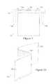
- FIG. 4shows a detailed vertical cross-section view through a second embodiment of an electronic reading device according to the invention
- FIG. 5shows a front window for the device of FIG. 4 , incorporating a touch-sensor
- FIG. 6shows a colour filter array for the device at FIG. 4 ;
- FIG. 7shows a display media layer for the device at FIG. 4 ;
- FIG. 8shows a substrate/backplane layer for the device at FIG. 4 mounting display interface electronics
- FIG. 9shows a front side of a flexible PCB for the device at FIG. 4 ;
- FIG. 10shows a rear face of the flexible PCB at FIG. 9 ;
- FIG. 11shows a view of the rear of the device at FIG. 4 when the back cover is not present
- FIG. 12shows a rear view of the device at FIG. 4 ;
- FIG. 13shows an edge profile of the device at FIG. 4 ;
- FIG. 14shows a block diagram of the device at FIG. 4 .
- thisshows a first embodiment of an electronic reading device 100 comprising a display part 102 and a handle 104 located at one edge of the display.
- New display part 102is flexible and self-supporting when held by the handle, but the device lacks an internal stiffening frame and instead relies upon the structure of the device itself to provide sufficient support. This is facilitated by the device being very thin, in embodiments less than 3 mm thick, and very light, in embodiments less than 200 grams (facilitated by the device being constructed mainly of plastic, including at least some of the functional electronic components of the device).
- the deviceis sealed and waterproof and has no physical external connections (power and communications are both exclusively wireless).
- the devicehas no separate housing or enclosure; instead the device or at least substantially the entirety of the display part of the device has a continuous, unitary structure which is integrally formed.
- substantially all internal voidsare filled with a gel-based encapsulation material, and the device is sealed around the edge in a similar manner.
- embodiments of the devicelack a bezel around the edge of the device, or at least around the edge of the display part of the device, facilitating flexibility and also foldability because the display portions in foldable embodiments may then be stacked neatly behind one another.
- a flexible, and in embodiments foldable deviceis further facilitated by the use of very thin battery technology, as described later.
- the screenis preferably touch sensitive although a single user control 106 may also be provided.
- Thismay, for example, comprise a refresh button that automatically refreshes data stored within the device via a wireless internet connection, for example one or more RSS (Really Simple Syndication) feeds via the internet.
- RSSReally Simple Syndication
- embodiments of the devicemay be configured to function as a ‘viewer’ for other electronic devices including, but not limited to: a laptop or desktop computer, a PDA (personal digital assistant), a mobile phone or smartphone, or the like.
- the electronic reading devicesprovided with wireless interfaces such as an infra-red or BluetoothTM interface and/or a WiFi or similar interface.
- wireless interfacessuch as an infra-red or BluetoothTM interface and/or a WiFi or similar interface.
- Embodiments of the deviceare configured to enable it to be used as a second screen or the primary screen of the ‘host’ electronic device.
- the displaygives the appearance of paper.
- the devicemay be configured so that it appears to the host device as a conventional, paper-based printer—for example enabling a document to be displayed on the device by opening the document and clicking print. This can be achieved by providing an appropriate printer driver for the host device (for example as described in our WO2009/053738) and providing corresponding software on the document reading device.
- the displaymay be borderless, to enhance the impression of ‘electronic paper’.
- the displaymay have the appearance of being borderless by cropping the margins of an image to be displayed and then arranging for the border of the electronic reading device to give the appearance of the margins so that, when displayed, the document page appears, to a viewer, to extend substantially to the edges of the device.
- borders of the deviceare coloured to match a white paper background.
- bordersmay be for example of width around 1 cm and extend to all the edges of the device (optionally excluding the handle part) and internal colouring is employed at a corresponding depth within the device to the active display media to reduce any visual discontinuity at the boundary of the active display region.
- FIG. 2shows an internal arrangement of the display interface electronics for the device at Figure one.
- the control electronics for the deviceare concealed within handle 104 .
- the display interface electronicscomprises a gate driver integrated circuit 108 and first and second source driver integrated circuits 110 a, b .
- the source lines of the displayare driven from opposite edges of the display and the gate lines are driven from the handle edge of the display, and thus connections 112 a, b between the source driver lines of the display backplane and the source driver integrated circuits 110 a, b run along edges of the display portion 102 , concealed under a thin border as previously described.
- the remainder of the device electronicscomprising communications, a micro controller, memory and so forth, may be mounted on a strip of printed circuit board within handle 104 .
- handle 104may be very thin.
- a battery for the devicemay either be distributed over part or all of the region of display part 102 or located within handle 104 .
- handle 104is foldable, which may be achieved by dividing the components between two parts within the handle connected by a flexible connector, for example a portion of flexible printed circuit board.
- the user experienceis that holding the device feels like merely holding just the display.
- FIGS. 3A and 3Bshow a foldable embodiment of the device 100 of FIG. 1 in which, in this example, the display stack comprises three portions 102 a, b, c which may be folded so that display portions 102 b, c are behind portion 102 a .
- Thisfacilitates changing between, for example, an A4/US letter format and a column format, for example having a width:height aspect ratio of greater than one:two—which is convenient for one-hand reading of documents and other material.
- the vertical hingese.g., hinges 2000
- Electrode lines across the hingemay be broken or, where these are continuous across the hinge, a flexible coupling such as flexible PCB may be employed.
- FIG. 4shows a vertical cross-section view through a second embodiment of an electronic reading device 400 in which electronic components of the device are distributed over a surface of the device on a flexible PCB. Nonetheless a display stack of the type illustrated in FIG. 4 may also be employed for the embodiment of FIG. 1 .
- the structurecomprises a substrate 402 , typically a plastic such as PET (polyethyleneterephthalate) or pen(polyethelenemaphthalene) on which is fabricated a thin layer of organic active matrix pixel circuitry.
- the circuitrymay comprise an array of organic (or inorganic) thin film transistors for example as previously described in our WO01/47045, WO2004/070466, WO01/47043, WO2006/059162, WO2006/056808, WO2006/061658, WO2006/106365 and WO2007/029028.
- the backplaneis fabricated using solution based techniques patterned by, for example, direct-right printing, laser ablation or photolithography to fabricate the thin film transistors.
- the active deviceshave a thickness of order 5-10 ⁇ m.
- this layerhas a thickness of order 50 ⁇ m and has integrated encapsulation.
- This substrate/backplane layerbears row and column, dataline and address conductive tracks 404 , connected to the rear of substrate 402 by vias 406 . We here refer to front as being towards the display surface of the device and rear as being towards the rear of the device.
- a display medium 408is attached to substrate 402 , for example by adhesive.
- the display mediumis a reflective display medium (which facilitates daylight reading), for example an electrophoretic display medium or an electrofluidic display medium.
- a colour displaymay be provided by providing a colour filter array 410 over the display medium; optionally this may also perform an encapsulation function.
- a moisture barriermay be provided over the display, for example comprising polyethylene and/or AclarTM (a fluoropolymer, polychlorotrifluoroethylene-PCTFE).
- the thickness of the display mediumis of order 75 ⁇ m and that of the encapsulation/colour filter array of order 120 ⁇ m.
- an electrofluidic displayfor example of the type available from Gamma Dynamics, Inc. Ohio USA, the colour filter array may be omitted.
- the use of an electrofluidic displayfacilitates improved brightness/contrast as well as near video display update rates and high resolution, in embodiments of order 225 pixels per inch.
- an edge seal 412is provided to seal the edge of display medium 408 to the edge of the display module.
- a front window 414is provided over the display, for example comprising a thin layer of PMMA (polymethylmethacrylate), in embodiments with a thickness of order 75 ⁇ m. Where the device is touch sensitive, this layer may also include conductive row and column lines for the touch circuitry, in embodiments employing fine line metal (FLM).
- the touch sensing circuitrymay be operable by finger and/or a stylus.
- a connection to the touch sensing layermay be made by a Z-axis conductive pad 416 which connects to the touch electrodes in window 414 through CFA/encapsulation layer 410 (for example by vias, not shown) and vias 418 through substrate 402 bring the touch array connections to contact pads on the rear of substrate 402 .
- An adhesive layer 420connects the substrate 402 to a flexible PCB 422 (which may incorporate circuitry 424 for an inductive stylus sensor. Connections between the contact pads on the rear of substrate 402 and the flexible PCB employ an isotropic conductive film (ACF) 426 .
- ACFisotropic conductive film
- Flexible PCB 422carries electronic components 428 , for example surface mounted components, and a thin film flexible polymer battery 430 .
- the PCB 422has a thickness of order 600 ⁇ m, and the components/battery have a thickness up to 800 ⁇ m.
- Flexible PCB 422also bears a conductive loop 432 around the border of the device for inductive charging of battery 430 .
- the components and batteryare provided with a thin rear cover 434 (optional).
- the display and PCB moduleis encapsulated, for example by a gel-based potting material or encapsulant 436 which, in embodiments, fills all the internal gaps, extending around the edge of the display module, over the flexible PCB, and attaching rear cover 434 .
- the displaymay be foldable in half or in thirds.
- the deviceentirely lacks mechanical controls and, in embodiments, all connections to the device are wireless; embodiments of the device lack speakers.
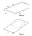
- FIGS. 5 to 13show perspective views of layers illustrated in the cross-section of FIG. 4 .
- FIG. 5shows plastic front window 414 which protects the display medium and, where present, the colour filter array.
- This windowhas a plurality of pads 414 a around the edge which connect to tracks on the touch sensor FLM (fine line metal) in the case of a capacitive sensor.
- the fine line metalhas a width in the range 2-5 ⁇ m.
- the window 414provides a narrow border 414 b around the active display area.
- FIG. 6shows a plan view of the colour filter array 410 , again with a narrow border. In embodiments this may provide a regular pattern of red, green, blue and white colours.
- FIG. 7shows the display medium 408 , with the active area of the media substantially following the entire available area.
- FIG. 8shows substrate 402 having an active backplane area 402 a for driving pixels of the display medium 408 .
- Substrate 402is provided with pads 402 b around the edge to carry touch signals between the touch electrodes of window 414 and touch sensing circuitry on PCB 422 .
- Substrate 402also bears a plurality of display driver integrated circuits 438 , mounted on substrate 402 using chip-on-plastic technology. Connections to these when made, for example, by other pads (now shown).
- FIG. 9shows the front (display-facing) face of flexible PCB 422 , illustrating pads 422 a around the border which connect to the display/touch sensing module via an isotropic conductive film.
- FIG. 10shows, schematically, the rear face of PCB 422 , illustrating the components 428 , battery location 430 and inductive loop 432 .
- FIG. 11is a similar illustration to FIG. 10 showing the flexible battery 430 in position.
- the electronic components 428include, in embodiments a single chip processor, a display engine, and BluetoothTM/near-field communications.
- the battery 430may be recharged by holding the device over an inductive charging pad, but in alternative approaches a capacitive charge electrode may be employed for capacitive charging.
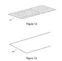
- FIG. 12shows a rear view of the device 400 , illustrating the thinness of the device—in embodiments the device is of order 2 mm thick.
- FIG. 13shows an edge profile of the device formed by encapsulant 436 .
- FIG. 14shows a block diagram of the electronics of the device of FIG. 4 .
- the devicecomprises a controller 1002 including a processor, for example an ARMTM device, working memory and program memory coupled to one or more display interface integrated circuits 438 for driving the electrophoretic/electrofluidic display 408 .
- One or more touch interface integrated circuits 1006interface with the touch electrodes on front window 414 to provide touch data to controller 1002 .
- the program memoryin embodiments stores processor control code to implement functions including an operating system, various types of wireless interface, document retrieval, storage, annotation (via the touch interface) and export from the device.
- the stored codealso includes code 1003 to implement a document viewer/‘printerless printing’ function, for example interfacing with corresponding driver code on a ‘host’ device.
- the controller 1002interfaces with non-volatile memory, for example Flash memory, for storing one or more documents for display and, optionally, other data such as user bookmark locations and the like.
- non-volatile memoryfor example Flash memory
- other datasuch as user bookmark locations and the like.
- a mechanical user control 1004may also be provided.
- a wireless interface 1010for example a BluetoothTM or WiFi interface is provided for interfacing with a consumer electronic device such as a phone 1014 a , laptop 1014 b or the like.
- inductive loop 432is used to charge the chargeable battery 430 which has associated circuitry for providing a regulated power supply to the system.
Landscapes
- Engineering & Computer Science (AREA)
- Computer Hardware Design (AREA)
- Theoretical Computer Science (AREA)
- Physics & Mathematics (AREA)
- General Engineering & Computer Science (AREA)
- General Physics & Mathematics (AREA)
- Human Computer Interaction (AREA)
- Devices For Indicating Variable Information By Combining Individual Elements (AREA)
- Microelectronics & Electronic Packaging (AREA)
- Computing Systems (AREA)
- Electrochromic Elements, Electrophoresis, Or Variable Reflection Or Absorption Elements (AREA)
- Electroluminescent Light Sources (AREA)
Abstract
Description
Claims (7)
Applications Claiming Priority (3)
| Application Number | Priority Date | Filing Date | Title |
|---|---|---|---|
| GB1209033.8AGB2502305B (en) | 2012-05-22 | 2012-05-22 | Electronic reading devices |
| GB1209033.8 | 2012-05-22 | ||
| PCT/GB2013/051344WO2013175212A2 (en) | 2012-05-22 | 2013-05-22 | Electronic reading devices |
Publications (2)
| Publication Number | Publication Date |
|---|---|
| US20150138736A1 US20150138736A1 (en) | 2015-05-21 |
| US9807876B2true US9807876B2 (en) | 2017-10-31 |
Family
ID=46546507
Family Applications (1)
| Application Number | Title | Priority Date | Filing Date |
|---|---|---|---|
| US14/403,157Active2033-07-30US9807876B2 (en) | 2012-05-22 | 2013-05-22 | Electronic reading device |
Country Status (5)
| Country | Link |
|---|---|
| US (1) | US9807876B2 (en) |
| CN (1) | CN104350445B (en) |
| DE (1) | DE112013002646T5 (en) |
| GB (1) | GB2502305B (en) |
| WO (1) | WO2013175212A2 (en) |
Cited By (15)
| Publication number | Priority date | Publication date | Assignee | Title |
|---|---|---|---|---|
| US11081684B2 (en) | 2017-05-24 | 2021-08-03 | Honda Motor Co., Ltd. | Production of carbon nanotube modified battery electrode powders via single step dispersion |
| US11121358B2 (en) | 2017-09-15 | 2021-09-14 | Honda Motor Co., Ltd. | Method for embedding a battery tab attachment in a self-standing electrode without current collector or binder |
| US11171324B2 (en) | 2016-03-15 | 2021-11-09 | Honda Motor Co., Ltd. | System and method of producing a composite product |
| US11201318B2 (en) | 2017-09-15 | 2021-12-14 | Honda Motor Co., Ltd. | Method for battery tab attachment to a self-standing electrode |
| US11325833B2 (en) | 2019-03-04 | 2022-05-10 | Honda Motor Co., Ltd. | Composite yarn and method of making a carbon nanotube composite yarn |
| US11352258B2 (en) | 2019-03-04 | 2022-06-07 | Honda Motor Co., Ltd. | Multifunctional conductive wire and method of making |
| US11374214B2 (en) | 2017-07-31 | 2022-06-28 | Honda Motor Co., Ltd. | Self standing electrodes and methods for making thereof |
| US11383213B2 (en) | 2016-03-15 | 2022-07-12 | Honda Motor Co., Ltd. | System and method of producing a composite product |
| US11539042B2 (en) | 2019-07-19 | 2022-12-27 | Honda Motor Co., Ltd. | Flexible packaging with embedded electrode and method of making |
| US11535517B2 (en) | 2019-01-24 | 2022-12-27 | Honda Motor Co., Ltd. | Method of making self-standing electrodes supported by carbon nanostructured filaments |
| US11569490B2 (en) | 2017-07-31 | 2023-01-31 | Honda Motor Co., Ltd. | Continuous production of binder and collector-less self-standing electrodes for Li-ion batteries by using carbon nanotubes as an additive |
| US11653556B2 (en)* | 2019-12-30 | 2023-05-16 | Interface Technology (ChengDu) Co, Ltd. | Flex-tolerant structure, and display panel using same |
| US12142771B2 (en) | 2019-01-30 | 2024-11-12 | Honda Motor Co., Ltd. | Flexible battery as an integration platform for wearable sensors and processing/transmitting devices |
| US12360568B2 (en) | 2014-11-28 | 2025-07-15 | Semiconductor Energy Laboratory Co., Ltd. | Electronic device |
| US12381275B2 (en) | 2019-01-30 | 2025-08-05 | Honda Motor Co., Ltd. | Stretchable and flexible lithium ion battery |
Families Citing this family (17)
| Publication number | Priority date | Publication date | Assignee | Title |
|---|---|---|---|---|
| US20110298760A1 (en) | 2010-06-02 | 2011-12-08 | Omer Gila | Systems and methods for writing on and using electronic paper |
| USD778248S1 (en)* | 2013-04-08 | 2017-02-07 | Lg Electronics Inc. | Television receiver |
| USD778249S1 (en)* | 2013-04-08 | 2017-02-07 | Lg Electronics Inc. | Television receiver |
| US20150029413A1 (en)* | 2013-07-28 | 2015-01-29 | Himax Technologies Limited | Touch display apparatus |
| US20160291641A1 (en)* | 2013-12-26 | 2016-10-06 | Intel Corporation | Method and apparatus for flexible electronic communicating device |
| WO2015116214A2 (en) | 2014-01-31 | 2015-08-06 | Hewlett-Packard Development Company, L.P. | E-paper display media |
| WO2015116211A1 (en) | 2014-01-31 | 2015-08-06 | Hewlett-Packard Development Company, L.P. | Display device |
| KR102174323B1 (en)* | 2014-05-27 | 2020-11-05 | 삼성디스플레이 주식회사 | Gate driving circuit and display device having the same |
| JP2016057617A (en)* | 2014-09-05 | 2016-04-21 | 株式会社半導体エネルギー研究所 | Electronic device |
| US9778772B2 (en) | 2015-09-16 | 2017-10-03 | Microsoft Technology Licensing, Llc | Bendable device with display in movable connection with body |
| CN107491203B (en) | 2016-06-13 | 2020-08-11 | 元太科技工业股份有限公司 | touch display device |
| US10418237B2 (en)* | 2016-11-23 | 2019-09-17 | United States Of America As Represented By The Secretary Of The Air Force | Amorphous boron nitride dielectric |
| CN106847864B (en)* | 2017-01-09 | 2019-11-12 | 张一帆 | A kind of narrow frame touch-control display panel and display device and preparation method thereof |
| US20190146742A1 (en)* | 2017-11-15 | 2019-05-16 | Futurewei Technologies, Inc. | Providing enriched e-reading experience in multi-display environments |
| CN111542868B (en)* | 2017-12-26 | 2023-09-12 | 索尼公司 | Display apparatus |
| KR102499112B1 (en)* | 2018-04-09 | 2023-02-13 | 삼성전자 주식회사 | Electronic device equipped with flexible display and method for wireless charging thereof` |
| KR102586636B1 (en) | 2018-10-11 | 2023-10-11 | 삼성디스플레이 주식회사 | Foldable display device |
Citations (35)
| Publication number | Priority date | Publication date | Assignee | Title |
|---|---|---|---|---|
| US5177596A (en)* | 1989-08-28 | 1993-01-05 | Seiko Epson Corporation | Electronic component mounting structures for fpc tape carrier and methods of separation and application |
| US5478006A (en)* | 1993-05-24 | 1995-12-26 | Sharp Kabushiki Kaisha | Printed-circuit substrate and its connecting method |
| US5986726A (en)* | 1997-11-17 | 1999-11-16 | Kabushiki Kaisha Toshiba | Flat panel display device |
| US6118665A (en)* | 1997-03-19 | 2000-09-12 | Fujitsu Limited | Flexible printed circuit and connected printed circuit structure |
| GB2378034A (en) | 2001-05-31 | 2003-01-29 | Hewlett Packard Co | Flexible electronic viewing device |
| GB2380824A (en)* | 2001-10-11 | 2003-04-16 | Stephen John Smith | Digital electronic book and newspaper reading device |
| WO2003034137A2 (en) | 2001-10-16 | 2003-04-24 | Hewlett-Packard Company | Portable electronic reading apparatus |
| US20030227441A1 (en) | 2002-03-29 | 2003-12-11 | Kabushiki Kaisha Toshiba | Display input device and display input system |
| US20060146488A1 (en) | 2005-01-05 | 2006-07-06 | Nokia Corporation | Foldable electronic device and a flexible display device |
| US20060229117A1 (en)* | 2005-04-07 | 2006-10-12 | Nokia Corporation | Mobile communication terminal |
| US20060242556A1 (en) | 2005-04-25 | 2006-10-26 | Fuji Xerox Co., Ltd. | Document processing system |
| US20070247792A1 (en)* | 2006-04-20 | 2007-10-25 | Yang Jun H | Computer screen |
| WO2007144549A1 (en) | 2006-06-12 | 2007-12-21 | Plastic Logic Limited | Electronic document reading device |
| US20080055303A1 (en)* | 2006-08-31 | 2008-03-06 | Seiko Epson Corporation | Display unit and electronic device |
| US7408263B2 (en)* | 2005-05-03 | 2008-08-05 | E.I. Du Pont De Nemours And Company | Anisotropic conductive coatings and electronic devices |
| US20080297496A1 (en)* | 2007-02-07 | 2008-12-04 | Ben Watson | Electronic document reading devices |
| US20090000169A1 (en)* | 2007-06-14 | 2009-01-01 | Vazgen Houssain | Portable presentation display device |
| GB2454030A (en) | 2007-10-24 | 2009-04-29 | Plastic Logic Ltd | Edgeless display device |
| US20100060563A1 (en)* | 2008-09-05 | 2010-03-11 | Plastic Logic Limited | Electronic document reader |
| WO2010041227A1 (en) | 2008-10-12 | 2010-04-15 | Barit, Efrat | Flexible devices and related methods of use |
| US20100277443A1 (en) | 2009-05-02 | 2010-11-04 | Semiconductor Energy Laboratory Co., Ltd. | Electronic Book |
| DE202010008706U1 (en) | 2010-08-04 | 2011-01-05 | Mirco-Star International Corp. Ltd., Jhonghe City | Collapsible electronic device |
| CN102201175A (en) | 2010-03-26 | 2011-09-28 | 上海易狄欧电子科技有限公司 | Handheld electronic book reader |
| JP2012048094A (en) | 2010-08-30 | 2012-03-08 | Seiko Epson Corp | Information display terminal |
| US8207947B2 (en)* | 2007-02-07 | 2012-06-26 | Plastic Logic Limited | Electronic document readers and reading devices |
| US20130107476A1 (en)* | 2011-10-28 | 2013-05-02 | Derek Wright | Display with Vias for Concealed Printed Circuit and Component Attachment |
| US20140073074A1 (en)* | 2006-12-14 | 2014-03-13 | Plastic Logic Limited | Distortion tolerant pixel design |
| US20140098075A1 (en)* | 2012-10-04 | 2014-04-10 | Samsung Electronics Co., Ltd. | Flexible display apparatus and control method thereof |
| US20150192953A1 (en)* | 2014-01-08 | 2015-07-09 | David Michael Meyers | Portfolio cover for portable information handling systems |
| US20150198978A1 (en)* | 2012-08-13 | 2015-07-16 | Plastic Logic Limited | Electronic device |
| US20150277496A1 (en)* | 2012-10-08 | 2015-10-01 | Flexenable Limited | Foldable electronic display |
| US9195358B1 (en)* | 2014-04-16 | 2015-11-24 | Eastman Kodak Company | Z-fold multi-element substrate structure |
| US20150351232A1 (en)* | 2014-04-16 | 2015-12-03 | Ronald Steven Cok | Making z-fold multi-element substrate structure |
| US20160048167A1 (en)* | 2014-08-13 | 2016-02-18 | Dell Products L.P. | Bezel for Providing Improved User Experience |
| US9307061B2 (en)* | 2011-05-12 | 2016-04-05 | Nokia Technologies Oy | Flexible electronic apparatus |
Family Cites Families (2)
| Publication number | Priority date | Publication date | Assignee | Title |
|---|---|---|---|---|
| CN101763826B (en)* | 2008-12-25 | 2012-06-06 | 佛山市顺德区顺达电脑厂有限公司 | Thin-shaped display device and electronic paper display picture control method thereof |
| CN101813863A (en)* | 2009-02-24 | 2010-08-25 | 元太科技工业股份有限公司 | Flexible display panel and manufacturing method thereof |
- 2012
- 2012-05-22GBGB1209033.8Apatent/GB2502305B/ennot_activeExpired - Fee Related
- 2013
- 2013-05-22USUS14/403,157patent/US9807876B2/enactiveActive
- 2013-05-22DEDE112013002646.5Tpatent/DE112013002646T5/ennot_activeWithdrawn
- 2013-05-22CNCN201380027052.1Apatent/CN104350445B/ennot_activeExpired - Fee Related
- 2013-05-22WOPCT/GB2013/051344patent/WO2013175212A2/enactiveApplication Filing
Patent Citations (37)
| Publication number | Priority date | Publication date | Assignee | Title |
|---|---|---|---|---|
| US5177596A (en)* | 1989-08-28 | 1993-01-05 | Seiko Epson Corporation | Electronic component mounting structures for fpc tape carrier and methods of separation and application |
| US5478006A (en)* | 1993-05-24 | 1995-12-26 | Sharp Kabushiki Kaisha | Printed-circuit substrate and its connecting method |
| US6118665A (en)* | 1997-03-19 | 2000-09-12 | Fujitsu Limited | Flexible printed circuit and connected printed circuit structure |
| US5986726A (en)* | 1997-11-17 | 1999-11-16 | Kabushiki Kaisha Toshiba | Flat panel display device |
| GB2378034A (en) | 2001-05-31 | 2003-01-29 | Hewlett Packard Co | Flexible electronic viewing device |
| GB2380824A (en)* | 2001-10-11 | 2003-04-16 | Stephen John Smith | Digital electronic book and newspaper reading device |
| WO2003034137A2 (en) | 2001-10-16 | 2003-04-24 | Hewlett-Packard Company | Portable electronic reading apparatus |
| US20030227441A1 (en) | 2002-03-29 | 2003-12-11 | Kabushiki Kaisha Toshiba | Display input device and display input system |
| US20060146488A1 (en) | 2005-01-05 | 2006-07-06 | Nokia Corporation | Foldable electronic device and a flexible display device |
| US20060229117A1 (en)* | 2005-04-07 | 2006-10-12 | Nokia Corporation | Mobile communication terminal |
| US20060242556A1 (en) | 2005-04-25 | 2006-10-26 | Fuji Xerox Co., Ltd. | Document processing system |
| US7408263B2 (en)* | 2005-05-03 | 2008-08-05 | E.I. Du Pont De Nemours And Company | Anisotropic conductive coatings and electronic devices |
| US20070247792A1 (en)* | 2006-04-20 | 2007-10-25 | Yang Jun H | Computer screen |
| WO2007144549A1 (en) | 2006-06-12 | 2007-12-21 | Plastic Logic Limited | Electronic document reading device |
| US20080055303A1 (en)* | 2006-08-31 | 2008-03-06 | Seiko Epson Corporation | Display unit and electronic device |
| US20140073074A1 (en)* | 2006-12-14 | 2014-03-13 | Plastic Logic Limited | Distortion tolerant pixel design |
| US20080297496A1 (en)* | 2007-02-07 | 2008-12-04 | Ben Watson | Electronic document reading devices |
| US8207947B2 (en)* | 2007-02-07 | 2012-06-26 | Plastic Logic Limited | Electronic document readers and reading devices |
| US20090000169A1 (en)* | 2007-06-14 | 2009-01-01 | Vazgen Houssain | Portable presentation display device |
| US20090113291A1 (en)* | 2007-10-24 | 2009-04-30 | Plastic Logic Limited | Electronic Document Reader |
| GB2454030A (en) | 2007-10-24 | 2009-04-29 | Plastic Logic Ltd | Edgeless display device |
| US20100060563A1 (en)* | 2008-09-05 | 2010-03-11 | Plastic Logic Limited | Electronic document reader |
| WO2010041227A1 (en) | 2008-10-12 | 2010-04-15 | Barit, Efrat | Flexible devices and related methods of use |
| US20100277443A1 (en) | 2009-05-02 | 2010-11-04 | Semiconductor Energy Laboratory Co., Ltd. | Electronic Book |
| WO2010128616A1 (en) | 2009-05-02 | 2010-11-11 | Semiconductor Energy Laboratory Co., Ltd. | Electronic book |
| CN102201175A (en) | 2010-03-26 | 2011-09-28 | 上海易狄欧电子科技有限公司 | Handheld electronic book reader |
| DE202010008706U1 (en) | 2010-08-04 | 2011-01-05 | Mirco-Star International Corp. Ltd., Jhonghe City | Collapsible electronic device |
| JP2012048094A (en) | 2010-08-30 | 2012-03-08 | Seiko Epson Corp | Information display terminal |
| US9307061B2 (en)* | 2011-05-12 | 2016-04-05 | Nokia Technologies Oy | Flexible electronic apparatus |
| US20130107476A1 (en)* | 2011-10-28 | 2013-05-02 | Derek Wright | Display with Vias for Concealed Printed Circuit and Component Attachment |
| US20150198978A1 (en)* | 2012-08-13 | 2015-07-16 | Plastic Logic Limited | Electronic device |
| US20140098075A1 (en)* | 2012-10-04 | 2014-04-10 | Samsung Electronics Co., Ltd. | Flexible display apparatus and control method thereof |
| US20150277496A1 (en)* | 2012-10-08 | 2015-10-01 | Flexenable Limited | Foldable electronic display |
| US20150192953A1 (en)* | 2014-01-08 | 2015-07-09 | David Michael Meyers | Portfolio cover for portable information handling systems |
| US9195358B1 (en)* | 2014-04-16 | 2015-11-24 | Eastman Kodak Company | Z-fold multi-element substrate structure |
| US20150351232A1 (en)* | 2014-04-16 | 2015-12-03 | Ronald Steven Cok | Making z-fold multi-element substrate structure |
| US20160048167A1 (en)* | 2014-08-13 | 2016-02-18 | Dell Products L.P. | Bezel for Providing Improved User Experience |
Non-Patent Citations (4)
| Title |
|---|
| Great Britain Examination Report dated Oct. 28, 2014 for Application No. GB1209033.8. |
| International Search Report and Written Opinion dated Apr. 29, 2014 for International Application No. PCT/GB2013/051344. |
| International Search Report and Written Opinion dated Nov. 25, 2014 for International Application No. PCT/GB2013/051344. |
| Search Report received in Great Britain Patent Application No. GB1209033.8 dated Apr. 30, 2013 in 2 pages. |
Cited By (20)
| Publication number | Priority date | Publication date | Assignee | Title |
|---|---|---|---|---|
| US12360568B2 (en) | 2014-11-28 | 2025-07-15 | Semiconductor Energy Laboratory Co., Ltd. | Electronic device |
| US11888152B2 (en) | 2016-03-15 | 2024-01-30 | Honda Motor Co., Ltd. | System and method of producing a composite product |
| US11171324B2 (en) | 2016-03-15 | 2021-11-09 | Honda Motor Co., Ltd. | System and method of producing a composite product |
| US11383213B2 (en) | 2016-03-15 | 2022-07-12 | Honda Motor Co., Ltd. | System and method of producing a composite product |
| US11735705B2 (en) | 2017-05-24 | 2023-08-22 | Honda Motor Co., Ltd. | Production of carbon nanotube modified battery electrode powders via single step dispersion |
| US11081684B2 (en) | 2017-05-24 | 2021-08-03 | Honda Motor Co., Ltd. | Production of carbon nanotube modified battery electrode powders via single step dispersion |
| US11374214B2 (en) | 2017-07-31 | 2022-06-28 | Honda Motor Co., Ltd. | Self standing electrodes and methods for making thereof |
| US11569490B2 (en) | 2017-07-31 | 2023-01-31 | Honda Motor Co., Ltd. | Continuous production of binder and collector-less self-standing electrodes for Li-ion batteries by using carbon nanotubes as an additive |
| US11489147B2 (en) | 2017-09-15 | 2022-11-01 | Honda Motor Co., Ltd. | Method for embedding a battery tab attachment in a self-standing electrode without current collector or binder |
| US11201318B2 (en) | 2017-09-15 | 2021-12-14 | Honda Motor Co., Ltd. | Method for battery tab attachment to a self-standing electrode |
| US11616221B2 (en) | 2017-09-15 | 2023-03-28 | Honda Motor Co., Ltd. | Method for battery tab attachment to a self-standing electrode |
| US11121358B2 (en) | 2017-09-15 | 2021-09-14 | Honda Motor Co., Ltd. | Method for embedding a battery tab attachment in a self-standing electrode without current collector or binder |
| US11535517B2 (en) | 2019-01-24 | 2022-12-27 | Honda Motor Co., Ltd. | Method of making self-standing electrodes supported by carbon nanostructured filaments |
| US12381275B2 (en) | 2019-01-30 | 2025-08-05 | Honda Motor Co., Ltd. | Stretchable and flexible lithium ion battery |
| US12142771B2 (en) | 2019-01-30 | 2024-11-12 | Honda Motor Co., Ltd. | Flexible battery as an integration platform for wearable sensors and processing/transmitting devices |
| US11352258B2 (en) | 2019-03-04 | 2022-06-07 | Honda Motor Co., Ltd. | Multifunctional conductive wire and method of making |
| US11834335B2 (en) | 2019-03-04 | 2023-12-05 | Honda Motor Co., Ltd. | Article having multifunctional conductive wire |
| US11325833B2 (en) | 2019-03-04 | 2022-05-10 | Honda Motor Co., Ltd. | Composite yarn and method of making a carbon nanotube composite yarn |
| US11539042B2 (en) | 2019-07-19 | 2022-12-27 | Honda Motor Co., Ltd. | Flexible packaging with embedded electrode and method of making |
| US11653556B2 (en)* | 2019-12-30 | 2023-05-16 | Interface Technology (ChengDu) Co, Ltd. | Flex-tolerant structure, and display panel using same |
Also Published As
| Publication number | Publication date |
|---|---|
| CN104350445A (en) | 2015-02-11 |
| US20150138736A1 (en) | 2015-05-21 |
| WO2013175212A3 (en) | 2014-06-19 |
| GB2502305B (en) | 2015-07-29 |
| GB201209033D0 (en) | 2012-07-04 |
| CN104350445B (en) | 2018-07-24 |
| GB2502305A (en) | 2013-11-27 |
| DE112013002646T5 (en) | 2015-03-26 |
| WO2013175212A2 (en) | 2013-11-28 |
Similar Documents
| Publication | Publication Date | Title |
|---|---|---|
| US9807876B2 (en) | Electronic reading device | |
| US20150277496A1 (en) | Foldable electronic display | |
| RU2586865C2 (en) | Electronic document reading devices | |
| US8243424B1 (en) | Surface display assemblies | |
| US20150198978A1 (en) | Electronic device | |
| EP3642822B1 (en) | Electronic device including flexible display panel | |
| US9001024B2 (en) | Electronic document reader | |
| CN106486010B (en) | Support frame for flexible display and flexible display device including the same | |
| CN102763055B (en) | transparent electronics | |
| TWI555456B (en) | Foldable display apparatus | |
| US8203546B2 (en) | Electronic document reading devices | |
| US8228323B2 (en) | Electronic document reader system | |
| US11729932B2 (en) | Foldable display device | |
| EP2527962B1 (en) | Integrated digitizer display | |
| CN109688245A (en) | Electronic device with display module | |
| CN203849728U (en) | Double-screen electronic equipment | |
| CN104813251B (en) | Electronic equipment | |
| US20160140882A1 (en) | Assembly of multiple flexible displays | |
| US12164334B2 (en) | Display device and electronic device including the same | |
| CN106843560B (en) | Touch Sensors, Touch Panels and Electronic Devices | |
| CN206712857U (en) | A kind of display device | |
| US8345073B1 (en) | Touch screen layer reduction | |
| US9819815B1 (en) | Surface display assembly having proximate active elements | |
| US8427819B1 (en) | Substrate interconnect routing | |
| US20250203002A1 (en) | Display assembly with multi-segment flex |
Legal Events
| Date | Code | Title | Description |
|---|---|---|---|
| AS | Assignment | Owner name:FLEXENABLE LIMITED, UNITED KINGDOM Free format text:CHANGE OF NAME;ASSIGNOR:PLASTIC LOGIC LIMITED;REEL/FRAME:036175/0809 Effective date:20150130 | |
| AS | Assignment | Owner name:PLASTIC LOGIC LIMITED, UNITED KINGDOM Free format text:ASSIGNMENT OF ASSIGNORS INTEREST;ASSIGNOR:CATCHPOLE, MARK;REEL/FRAME:037107/0081 Effective date:20151026 | |
| FEPP | Fee payment procedure | Free format text:ENTITY STATUS SET TO UNDISCOUNTED (ORIGINAL EVENT CODE: BIG.) | |
| STCF | Information on status: patent grant | Free format text:PATENTED CASE | |
| MAFP | Maintenance fee payment | Free format text:PAYMENT OF MAINTENANCE FEE, 4TH YEAR, LARGE ENTITY (ORIGINAL EVENT CODE: M1551); ENTITY STATUS OF PATENT OWNER: LARGE ENTITY Year of fee payment:4 | |
| AS | Assignment | Owner name:FLEXENABLE TECHNOLOGY LIMITED, UNITED KINGDOM Free format text:ASSIGNMENT OF ASSIGNORS INTEREST;ASSIGNOR:FLEXENABLE LIMITED;REEL/FRAME:065281/0934 Effective date:20230419 | |
| FEPP | Fee payment procedure | Free format text:MAINTENANCE FEE REMINDER MAILED (ORIGINAL EVENT CODE: REM.); ENTITY STATUS OF PATENT OWNER: LARGE ENTITY |