US9806553B2 - Depletion MOSFET driver - Google Patents
Depletion MOSFET driverDownload PDFInfo
- Publication number
- US9806553B2 US9806553B2US13/928,250US201313928250AUS9806553B2US 9806553 B2US9806553 B2US 9806553B2US 201313928250 AUS201313928250 AUS 201313928250AUS 9806553 B2US9806553 B2US 9806553B2
- Authority
- US
- United States
- Prior art keywords
- terminal
- depletion
- voltage
- coupled
- transistor
- Prior art date
- Legal status (The legal status is an assumption and is not a legal conclusion. Google has not performed a legal analysis and makes no representation as to the accuracy of the status listed.)
- Active
Links
- 239000003990capacitorSubstances0.000claimsabstractdescription61
- 238000000034methodMethods0.000claimsdescription11
- 230000008901benefitEffects0.000description3
- 239000000969carrierSubstances0.000description3
- 230000005669field effectEffects0.000description2
- 239000010410layerSubstances0.000description2
- 238000010276constructionMethods0.000description1
- 230000003247decreasing effectEffects0.000description1
- 230000000779depleting effectEffects0.000description1
- 239000012535impuritySubstances0.000description1
- 238000012986modificationMethods0.000description1
- 230000004048modificationEffects0.000description1
- 239000004065semiconductorSubstances0.000description1
- 238000000638solvent extractionMethods0.000description1
- 239000000758substrateSubstances0.000description1
- 239000002344surface layerSubstances0.000description1
- 238000004804windingMethods0.000description1
Images

Classifications
- H—ELECTRICITY
- H02—GENERATION; CONVERSION OR DISTRIBUTION OF ELECTRIC POWER
- H02J—CIRCUIT ARRANGEMENTS OR SYSTEMS FOR SUPPLYING OR DISTRIBUTING ELECTRIC POWER; SYSTEMS FOR STORING ELECTRIC ENERGY
- H02J7/00—Circuit arrangements for charging or depolarising batteries or for supplying loads from batteries
- H02J7/00032—Circuit arrangements for charging or depolarising batteries or for supplying loads from batteries characterised by data exchange
- H02J7/00034—Charger exchanging data with an electronic device, i.e. telephone, whose internal battery is under charge
- H02J7/025—
- H—ELECTRICITY
- H02—GENERATION; CONVERSION OR DISTRIBUTION OF ELECTRIC POWER
- H02J—CIRCUIT ARRANGEMENTS OR SYSTEMS FOR SUPPLYING OR DISTRIBUTING ELECTRIC POWER; SYSTEMS FOR STORING ELECTRIC ENERGY
- H02J50/00—Circuit arrangements or systems for wireless supply or distribution of electric power
- H02J50/10—Circuit arrangements or systems for wireless supply or distribution of electric power using inductive coupling
- H02J50/12—Circuit arrangements or systems for wireless supply or distribution of electric power using inductive coupling of the resonant type
- H—ELECTRICITY
- H02—GENERATION; CONVERSION OR DISTRIBUTION OF ELECTRIC POWER
- H02J—CIRCUIT ARRANGEMENTS OR SYSTEMS FOR SUPPLYING OR DISTRIBUTING ELECTRIC POWER; SYSTEMS FOR STORING ELECTRIC ENERGY
- H02J50/00—Circuit arrangements or systems for wireless supply or distribution of electric power
- H02J50/20—Circuit arrangements or systems for wireless supply or distribution of electric power using microwaves or radio frequency waves
- H—ELECTRICITY
- H02—GENERATION; CONVERSION OR DISTRIBUTION OF ELECTRIC POWER
- H02J—CIRCUIT ARRANGEMENTS OR SYSTEMS FOR SUPPLYING OR DISTRIBUTING ELECTRIC POWER; SYSTEMS FOR STORING ELECTRIC ENERGY
- H02J50/00—Circuit arrangements or systems for wireless supply or distribution of electric power
- H02J50/40—Circuit arrangements or systems for wireless supply or distribution of electric power using two or more transmitting or receiving devices
- H—ELECTRICITY
- H02—GENERATION; CONVERSION OR DISTRIBUTION OF ELECTRIC POWER
- H02J—CIRCUIT ARRANGEMENTS OR SYSTEMS FOR SUPPLYING OR DISTRIBUTING ELECTRIC POWER; SYSTEMS FOR STORING ELECTRIC ENERGY
- H02J50/00—Circuit arrangements or systems for wireless supply or distribution of electric power
- H02J50/80—Circuit arrangements or systems for wireless supply or distribution of electric power involving the exchange of data, concerning supply or distribution of electric power, between transmitting devices and receiving devices
- H—ELECTRICITY
- H02—GENERATION; CONVERSION OR DISTRIBUTION OF ELECTRIC POWER
- H02M—APPARATUS FOR CONVERSION BETWEEN AC AND AC, BETWEEN AC AND DC, OR BETWEEN DC AND DC, AND FOR USE WITH MAINS OR SIMILAR POWER SUPPLY SYSTEMS; CONVERSION OF DC OR AC INPUT POWER INTO SURGE OUTPUT POWER; CONTROL OR REGULATION THEREOF
- H02M3/00—Conversion of DC power input into DC power output
- H02M3/22—Conversion of DC power input into DC power output with intermediate conversion into AC
- H02M3/24—Conversion of DC power input into DC power output with intermediate conversion into AC by static converters
- H02M3/28—Conversion of DC power input into DC power output with intermediate conversion into AC by static converters using discharge tubes with control electrode or semiconductor devices with control electrode to produce the intermediate AC
- H02M3/325—Conversion of DC power input into DC power output with intermediate conversion into AC by static converters using discharge tubes with control electrode or semiconductor devices with control electrode to produce the intermediate AC using devices of a triode or a transistor type requiring continuous application of a control signal
- H02M3/335—Conversion of DC power input into DC power output with intermediate conversion into AC by static converters using discharge tubes with control electrode or semiconductor devices with control electrode to produce the intermediate AC using devices of a triode or a transistor type requiring continuous application of a control signal using semiconductor devices only
- H02M3/33507—Conversion of DC power input into DC power output with intermediate conversion into AC by static converters using discharge tubes with control electrode or semiconductor devices with control electrode to produce the intermediate AC using devices of a triode or a transistor type requiring continuous application of a control signal using semiconductor devices only with automatic control of the output voltage or current, e.g. flyback converters
- H—ELECTRICITY
- H03—ELECTRONIC CIRCUITRY
- H03K—PULSE TECHNIQUE
- H03K17/00—Electronic switching or gating, i.e. not by contact-making and –breaking
- H04B5/0037—
- H—ELECTRICITY
- H04—ELECTRIC COMMUNICATION TECHNIQUE
- H04B—TRANSMISSION
- H04B5/00—Near-field transmission systems, e.g. inductive or capacitive transmission systems
- H04B5/70—Near-field transmission systems, e.g. inductive or capacitive transmission systems specially adapted for specific purposes
- H04B5/79—Near-field transmission systems, e.g. inductive or capacitive transmission systems specially adapted for specific purposes for data transfer in combination with power transfer
- H—ELECTRICITY
- H02—GENERATION; CONVERSION OR DISTRIBUTION OF ELECTRIC POWER
- H02M—APPARATUS FOR CONVERSION BETWEEN AC AND AC, BETWEEN AC AND DC, OR BETWEEN DC AND DC, AND FOR USE WITH MAINS OR SIMILAR POWER SUPPLY SYSTEMS; CONVERSION OF DC OR AC INPUT POWER INTO SURGE OUTPUT POWER; CONTROL OR REGULATION THEREOF
- H02M3/00—Conversion of DC power input into DC power output
- H02M3/22—Conversion of DC power input into DC power output with intermediate conversion into AC
- H02M3/24—Conversion of DC power input into DC power output with intermediate conversion into AC by static converters
- H02M3/28—Conversion of DC power input into DC power output with intermediate conversion into AC by static converters using discharge tubes with control electrode or semiconductor devices with control electrode to produce the intermediate AC
- H02M3/325—Conversion of DC power input into DC power output with intermediate conversion into AC by static converters using discharge tubes with control electrode or semiconductor devices with control electrode to produce the intermediate AC using devices of a triode or a transistor type requiring continuous application of a control signal
- H02M3/335—Conversion of DC power input into DC power output with intermediate conversion into AC by static converters using discharge tubes with control electrode or semiconductor devices with control electrode to produce the intermediate AC using devices of a triode or a transistor type requiring continuous application of a control signal using semiconductor devices only
Definitions
- the present inventionis generally directed to the field of MOSFET drivers. More specifically, the present invention is directed to a depletion mode MOSFET driver.
- a metal-oxide-semiconductor field-effect transistoris a transistor used for amplifying or switching electronic signals.
- MOSFETmetal-oxide-semiconductor field-effect transistor
- a voltage drop across the oxideinduces a conducting channel between the source and drain contacts via the field effect.
- the term “enhancement mode”refers to the increase of conductivity with increase in oxide field that adds carriers to the channel, also referred to as the inversion layer.
- the enhancement-mode MOSFETa voltage is applied to the gate.
- the channelconsists of carriers in a surface impurity layer of opposite type to the substrate, and conductivity is decreased by application of a field that depletes carriers from this surface layer.
- Depletion-mode MOSFETsare doped so that a channel exists even with zero voltage from gate to source. As such, the depletion-mode MOSFET is turned ON without applying a voltage to the gate. To control the channel, a negative voltage is applied to the gate (for an n-channel device), depleting the channel, which reduces the current flow through the device.
- Depletion-mode MOSFETsare commonly used in driver circuits. To turn OFF the depletion-mode MOSFET, a negative gate-to-source voltage must be applied. This is typically done by utilizing voltage control to pull the gate voltage to ground.
- a driver circuitis configured using a depletion-mode MOSFET to supply an output voltage across an output capacitor.
- the driver circuitincludes a resistor positioned between two terminals of the MOSFET. In the case of an n-channel depletion-mode MOSFET, the resistor is coupled to the source and the gate.
- the circuitis a current controlled depletion driver that turns OFF the depletion-mode MOSFET by driving a reverse current through the resistor to establish a negative potential at the gate relative to the source.
- a Zener diodeis coupled between the source of the depletion-mode MOSFET and the output capacitor to establish a voltage differential between the output and the MOSFET source.
- a current driven depletion-mode MOSFET-based driver circuitincludes a depletion-mode MOSFET, an output capacitor, a transistor and a resistor.
- the depletion-mode MOSFEThas a first terminal, a second terminal and a gate, wherein the first terminal is coupled to a power supply.
- the output capacitoris coupled to the second terminal of the depletion-mode MOSFET.
- the transistorhas a first terminal to receive a driving voltage, a second terminal and a third terminal coupled to ground.
- the first terminal of the transistoris coupled to the output capacitor, and the second terminal of the transistor is coupled to the gate of the depletion-mode MOSFET.
- the resistorhas a first terminal and a second terminal.
- the first terminal of the resistoris coupled to the output capacitor and the second terminal of the depletion-mode MOSFET.
- the second terminal of the resistoris coupled to the gate of the depletion-mode MOSFET and the second terminal of the transistor.
- the depletion-mode MOSFETis a N-channel MOSFET, and the first terminal of the resistor is coupled to a source of the depletion-mode MOSFET.
- the depletion-mode MOSFETis a P-channel MOSFET, and the first terminal of the resistor is coupled to a drain of the depletion-mode MOSFET.
- the driver circuitalso includes a voltage divider coupled between the output capacitor and the first terminal of the transistor. In some embodiments, the voltage divider is configured to supply a turn ON voltage to a gate of the transistor when a voltage across the output capacitor is equal to or greater than a threshold voltage.
- a reverse currentflows through the resistor, thereby resulting in a negative voltage potential between the gate and the second terminal of the depletion-mode MOSFET which turns OFF the depletion-mode MOSFET.
- the reverse currentflows from the output capacitor, through the resistor, and through the transistor.
- the reverse current flowresults in the voltage across the output capacitor dropping, further wherein when the voltage across the output capacitor drops below a minimum value, the voltage supplied to the gate of the transistor drops below the turn ON voltage and the transistor turns OFF.
- the reverse currentstops and the depletion-mode MOSFET turns ON.
- the driver circuitalso includes a Zener diode having a cathode coupled to the second terminal of the depletion-mode MOSFET and an anode coupled to the output capacitor.
- the first terminal of the resistoris coupled to the cathode of the Zener diode and the second terminal of the depletion-mode MOSFET.
- the driver circuitincludes a depletion-mode MOSFET, an output capacitor, a Zener diode, a voltage divider, a transistor and a resistor.
- the depletion-mode MOSFEThas a first terminal, a second terminal and a gate, wherein the first terminal is coupled to a power supply.
- the Zener diodehas a cathode coupled to the second terminal of the depletion mode MOSFET and an anode coupled to a first terminal of the output capacitor.
- the voltage divideris coupled to the first terminal of the output capacitor.
- the transistorhas a first terminal to receive a driving voltage, a second terminal and a third terminal coupled to ground.
- the first terminal of the transistoris coupled to the voltage divider, and the second terminal of the transistor is coupled to the gate of the depletion-mode MOSFET.
- the resistorhas a first terminal and a second terminal. The first terminal of the resistor is coupled to the cathode of the Zener diode and the second terminal of the depletion-mode MOSFET. The second terminal of the resistor is coupled to the gate of the depletion-mode MOSFET and the second terminal of the transistor.
- a method of driving a depletion-mode MOSFET based driver circuitincludes configuring a driver circuit including a depletion-mode MOSFET, an output capacitor, a transistor and a resistor.
- the depletion-mode MOSFETincludes a first terminal coupled to a power supply, a second terminal coupled to the output capacitor and a gate.
- the transistorincludes a gate coupled to the output capacitor, a first terminal coupled to the gate of the depletion-mode MOSFET and a second terminal coupled to ground.
- the resistorincludes a first terminal coupled to the output capacitor and the second terminal of the depletion-mode MOSFET and a second terminal coupled to the gate of the depletion-mode MOSFET and the first terminal of the transistor.
- the methodalso included turning ON the transistor, thereby driving a reverse current through the resistor from the first terminal to the second terminal, resulting in a negative voltage potential between the gate of the depletion-mode MOSFET and the second terminal of the depletion-mode MOSFET which turns OFF the depletion-mode MOSFET.
- the reverse currentflows from the output capacitor, through the resistor, and through the transistor. In some embodiments, the reverse current flow results in the voltage across the output capacitor dropping, wherein when the voltage across the output capacitor drops below a minimum value, the voltage supplied to the gate of the transistor drops below a turn ON voltage of the transistor and the transistor turns OFF. In some embodiments, when the transistor turns OFF, the reverse current stops and the depletion-mode MOSFET turns ON. In some embodiments, the method also includes supplying a turn ON voltage to the gate of the transistor when a voltage across the output capacitor is equal to or greater than a threshold voltage.
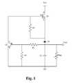
- FIG. 1illustrates a depletion-mode MOSFET driver circuit according to an embodiment.
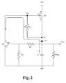
- FIG. 2illustrates reverse current flow in the depletion-mode MOSFET driver circuit of FIG. 1 .
- Embodiments of the present applicationare directed to a depletion MOSFET driver.
- Those of ordinary skill in the artwill realize that the following detailed description of the depletion MOSFET driver is illustrative only and is not intended to be in any way limiting. Other embodiments of the depletion MOSFET driver will readily suggest themselves to such skilled persons having the benefit of this disclosure.
- FIG. 1illustrates a depletion-mode MOSFET driver circuit according to an embodiment.
- the driving circuitincludes a depletion-mode MOSFET Q 1 , a Zenor diode Z 1 , a transistor Q 2 , resistors R 1 , R 2 and R 3 , capacitor C 1 , and a resistor RL that represents a load coupled to the capacitor C 1 .
- the depletion-mode MOSFET Q 1is an n-channel depletion-mode MOSFET and the transistor Q 2 is an NPN bipolar junction transistor (BJT). It is understood that the depletion-mode MOSFET Q 1 can alternatively be a p-channel depletion-mode MOSFET.
- the transistor Q 2can be an alternative type of transistor than a BJT.
- a Zener diodeis a diode which allows current to flow in the forward direction in the same manner as an ideal diode, but also permits current to flow in the reverse direction when the voltage is above a certain value.
- the depletion-mode MOSFET Q 1When connected to voltage supply Vcc, the natural state of the depletion-mode MOSFET Q 1 is ON when zero voltage is applied to the gate. When the depletion-mode MOSFET Q 1 is ON, current flows through the depletion-mode MOSFET Q 1 , through the Zener diode Z 1 , to the capacitor C 1 so that the capacitor C 1 becomes charged.
- a negative voltageneeds to be applied to the gate, or more specifically the gate-to-source voltage Vgs must be negative in which case the gate voltage is lower than the source voltage.
- the resistors R 1 and R 2form a voltage divider to supply a drive voltage to the gate of the transistor Q 2 .
- Vcc200V and the capacitor C 1 is charged to 15V.
- the resistors R 1 and R 2are configured to supply sufficient turn ON voltage to the gate of the transistor Q 2 when the capacitor C 1 has a threshold voltage, such as fully charged.
- the turn ON voltage for the transistor Q 2is approximately 1V and the voltage divider is configured to supply 1V to the gate of the transistor Q 2 when the capacitor C 1 is charged to 15V.
- the voltage drop across the Zener diode Z 1is 5V.
- the voltage Vs at the source of the depletion-mode MOSFET Q 1is 10V.
- the voltage at the gate of the transistor Q 2is sufficient to turn ON the transistor Q 2 .
- the transistor Q 2turns ON, a reverse current I flows from capacitor C 1 , through Zener diode Z 1 , through resistor R 3 , through the transistor Q 2 to ground, as shown in FIG. 2 .
- the reverse current through the resistor R 3establishes a negative potential at the gate of the depletion-mode MOSFET Q 1 relative to the source. This is a negative gate-to-source voltage Vgs, which turns OFF the depletion-mode MOSFET Q 1 .
- the resistor R 3has a resistance of 1 megaohm.
- This circuit configurationis a current controlled depletion driver that drives reverse current from the capacitor C 1 through the transistor Q 2 .
- Reverse currentis driven through the resistor R 3 toward the transistor Q 2 in order to turn OFF the depletion-mode MOSFET Q 1 .
- driving reverse current through the resistor R 3results in a voltage drop across resistor R 3 , which results in a negative gate-to-source voltage Vgs at the depletion-mode MOSFET Q 1 .
- Negative gate-to-source voltage Vgsturns OFF the depletion-mode MOSFET Q 1 .
- This current controlled driveris contrasted with conventional depletion-mode MOSFET drivers that utilize voltage control to turn OFF the depletion-mode MOSFET.
- the Zener diode Z 1establishes a voltage differential between the source voltage Vs and the output voltage Vout.
- the Zenor diode Z 1 and the capacitor C 1function as a current source when the transistor Q 2 is turned ON.
- the Zenor diode Z 1is also used as an extra bias element to establish a larger output voltage bandwidth within which the transistor Q 1 can be turned OFF.
- Another advantage of this circuitis that the leakage current of the depletion-mode MOSFET Q 1 is diverted with the reverse current flow to ground. The leakage current no longer flows to the output.
Landscapes
- Engineering & Computer Science (AREA)
- Power Engineering (AREA)
- Computer Networks & Wireless Communication (AREA)
- Signal Processing (AREA)
- Charge And Discharge Circuits For Batteries Or The Like (AREA)
- Electronic Switches (AREA)
- Dc-Dc Converters (AREA)
- Power Conversion In General (AREA)
Abstract
Description
This Patent Application claims priority under 35 U.S.C. 119 (e) of the U.S. Provisional Application Ser. No. 61/799,124, filed Mar. 15, 2013, and entitled “New Power Management Integrated Circuit Partitioning With Dedicated Primary Side Control Winding”. This application incorporates U.S. Provisional Application Ser. No. 61/799,124 in its entirety by reference.
The present invention is generally directed to the field of MOSFET drivers. More specifically, the present invention is directed to a depletion mode MOSFET driver.
A metal-oxide-semiconductor field-effect transistor (MOSFET) is a transistor used for amplifying or switching electronic signals. In enhancement mode MOSFETs, a voltage drop across the oxide induces a conducting channel between the source and drain contacts via the field effect. The term “enhancement mode” refers to the increase of conductivity with increase in oxide field that adds carriers to the channel, also referred to as the inversion layer. To turn ON the enhancement-mode MOSFET, a voltage is applied to the gate. In depletion mode MOSFETs, the channel consists of carriers in a surface impurity layer of opposite type to the substrate, and conductivity is decreased by application of a field that depletes carriers from this surface layer.
Depletion-mode MOSFETs are doped so that a channel exists even with zero voltage from gate to source. As such, the depletion-mode MOSFET is turned ON without applying a voltage to the gate. To control the channel, a negative voltage is applied to the gate (for an n-channel device), depleting the channel, which reduces the current flow through the device.
Depletion-mode MOSFETs are commonly used in driver circuits. To turn OFF the depletion-mode MOSFET, a negative gate-to-source voltage must be applied. This is typically done by utilizing voltage control to pull the gate voltage to ground.
A driver circuit is configured using a depletion-mode MOSFET to supply an output voltage across an output capacitor. The driver circuit includes a resistor positioned between two terminals of the MOSFET. In the case of an n-channel depletion-mode MOSFET, the resistor is coupled to the source and the gate. The circuit is a current controlled depletion driver that turns OFF the depletion-mode MOSFET by driving a reverse current through the resistor to establish a negative potential at the gate relative to the source. A Zener diode is coupled between the source of the depletion-mode MOSFET and the output capacitor to establish a voltage differential between the output and the MOSFET source.
In an aspect, a current driven depletion-mode MOSFET-based driver circuit is disclosed. The driver circuit includes a depletion-mode MOSFET, an output capacitor, a transistor and a resistor. The depletion-mode MOSFET has a first terminal, a second terminal and a gate, wherein the first terminal is coupled to a power supply. The output capacitor is coupled to the second terminal of the depletion-mode MOSFET. The transistor has a first terminal to receive a driving voltage, a second terminal and a third terminal coupled to ground. The first terminal of the transistor is coupled to the output capacitor, and the second terminal of the transistor is coupled to the gate of the depletion-mode MOSFET. The resistor has a first terminal and a second terminal. The first terminal of the resistor is coupled to the output capacitor and the second terminal of the depletion-mode MOSFET. The second terminal of the resistor is coupled to the gate of the depletion-mode MOSFET and the second terminal of the transistor.
In some embodiments, the depletion-mode MOSFET is a N-channel MOSFET, and the first terminal of the resistor is coupled to a source of the depletion-mode MOSFET. In other embodiments, the depletion-mode MOSFET is a P-channel MOSFET, and the first terminal of the resistor is coupled to a drain of the depletion-mode MOSFET. In some embodiments, the driver circuit also includes a voltage divider coupled between the output capacitor and the first terminal of the transistor. In some embodiments, the voltage divider is configured to supply a turn ON voltage to a gate of the transistor when a voltage across the output capacitor is equal to or greater than a threshold voltage.
In some embodiments, when the transistor is turned ON, a reverse current flows through the resistor, thereby resulting in a negative voltage potential between the gate and the second terminal of the depletion-mode MOSFET which turns OFF the depletion-mode MOSFET. In some embodiments, the reverse current flows from the output capacitor, through the resistor, and through the transistor. In some embodiments, the reverse current flow results in the voltage across the output capacitor dropping, further wherein when the voltage across the output capacitor drops below a minimum value, the voltage supplied to the gate of the transistor drops below the turn ON voltage and the transistor turns OFF. In some embodiments, when the transistor turns OFF, the reverse current stops and the depletion-mode MOSFET turns ON.
In some embodiments, the driver circuit also includes a Zener diode having a cathode coupled to the second terminal of the depletion-mode MOSFET and an anode coupled to the output capacitor. In some embodiments, the first terminal of the resistor is coupled to the cathode of the Zener diode and the second terminal of the depletion-mode MOSFET.
In another aspect, another current driven depletion-mode MOSFET-based driver circuit is disclosed. The driver circuit includes a depletion-mode MOSFET, an output capacitor, a Zener diode, a voltage divider, a transistor and a resistor. The depletion-mode MOSFET has a first terminal, a second terminal and a gate, wherein the first terminal is coupled to a power supply. The Zener diode has a cathode coupled to the second terminal of the depletion mode MOSFET and an anode coupled to a first terminal of the output capacitor. The voltage divider is coupled to the first terminal of the output capacitor. The transistor has a first terminal to receive a driving voltage, a second terminal and a third terminal coupled to ground. The first terminal of the transistor is coupled to the voltage divider, and the second terminal of the transistor is coupled to the gate of the depletion-mode MOSFET. The resistor has a first terminal and a second terminal. The first terminal of the resistor is coupled to the cathode of the Zener diode and the second terminal of the depletion-mode MOSFET. The second terminal of the resistor is coupled to the gate of the depletion-mode MOSFET and the second terminal of the transistor.
In yet another aspect, a method of driving a depletion-mode MOSFET based driver circuit is disclosed. The method includes configuring a driver circuit including a depletion-mode MOSFET, an output capacitor, a transistor and a resistor. The depletion-mode MOSFET includes a first terminal coupled to a power supply, a second terminal coupled to the output capacitor and a gate. The transistor includes a gate coupled to the output capacitor, a first terminal coupled to the gate of the depletion-mode MOSFET and a second terminal coupled to ground. The resistor includes a first terminal coupled to the output capacitor and the second terminal of the depletion-mode MOSFET and a second terminal coupled to the gate of the depletion-mode MOSFET and the first terminal of the transistor. The method also included turning ON the transistor, thereby driving a reverse current through the resistor from the first terminal to the second terminal, resulting in a negative voltage potential between the gate of the depletion-mode MOSFET and the second terminal of the depletion-mode MOSFET which turns OFF the depletion-mode MOSFET.
In some embodiments, the reverse current flows from the output capacitor, through the resistor, and through the transistor. In some embodiments, the reverse current flow results in the voltage across the output capacitor dropping, wherein when the voltage across the output capacitor drops below a minimum value, the voltage supplied to the gate of the transistor drops below a turn ON voltage of the transistor and the transistor turns OFF. In some embodiments, when the transistor turns OFF, the reverse current stops and the depletion-mode MOSFET turns ON. In some embodiments, the method also includes supplying a turn ON voltage to the gate of the transistor when a voltage across the output capacitor is equal to or greater than a threshold voltage.
Several example embodiments are described with reference to the drawings, wherein like components are provided with like reference numerals. The example embodiments are intended to illustrate, but not to limit, the invention. The drawings include the following figures:
Embodiments of the present application are directed to a depletion MOSFET driver. Those of ordinary skill in the art will realize that the following detailed description of the depletion MOSFET driver is illustrative only and is not intended to be in any way limiting. Other embodiments of the depletion MOSFET driver will readily suggest themselves to such skilled persons having the benefit of this disclosure.
Reference will now be made in detail to implementations of the depletion MOSFET driver as illustrated in the accompanying drawings. The same reference indicators will be used throughout the drawings and the following detailed description to refer to the same or like parts. In the interest of clarity, not all of the routine features of the implementations described herein are shown and described. It will, of course, be appreciated that in the development of any such actual implementation, numerous implementation-specific decisions must be made in order to achieve the developer's specific goals, such as compliance with application and business related constraints, and that these specific goals will vary from one implementation to another and from one developer to another. Moreover, it will be appreciated that such a development effort might be complex and time-consuming, but would nevertheless be a routine undertaking of engineering for those of ordinary skill in the art having the benefit of this disclosure.
When connected to voltage supply Vcc, the natural state of the depletion-mode MOSFET Q1 is ON when zero voltage is applied to the gate. When the depletion-mode MOSFET Q1 is ON, current flows through the depletion-mode MOSFET Q1, through the Zener diode Z1, to the capacitor C1 so that the capacitor C1 becomes charged.
To turn OFF the depletion-mode MOSFET Q1, a negative voltage needs to be applied to the gate, or more specifically the gate-to-source voltage Vgs must be negative in which case the gate voltage is lower than the source voltage.
The resistors R1 and R2 form a voltage divider to supply a drive voltage to the gate of the transistor Q2. In an exemplary application, Vcc=200V and the capacitor C1 is charged to 15V. The resistors R1 and R2 are configured to supply sufficient turn ON voltage to the gate of the transistor Q2 when the capacitor C1 has a threshold voltage, such as fully charged. In an exemplary application, the turn ON voltage for the transistor Q2 is approximately 1V and the voltage divider is configured to supply 1V to the gate of the transistor Q2 when the capacitor C1 is charged to 15V.
In an exemplary application, the voltage drop across the Zener diode Z1 is 5V. When capacitor C1 is charged at 15V, the voltage Vs at the source of the depletion-mode MOSFET Q1 is 10V. With the voltage across the capacitor C1 at least at the threshold voltage, the voltage at the gate of the transistor Q2 is sufficient to turn ON the transistor Q2. When the transistor Q2 turns ON, a reverse current I flows from capacitor C1, through Zener diode Z1, through resistor R3, through the transistor Q2 to ground, as shown inFIG. 2 . With reverse current flow through the resistor R3, there is a voltage drop VR3 across resistor R3, and therefore the voltage Vg at the gate of the transistor Q1 is less than the voltage Vs at the source, Vg=Vs−VR3. The reverse current through the resistor R3 establishes a negative potential at the gate of the depletion-mode MOSFET Q1 relative to the source. This is a negative gate-to-source voltage Vgs, which turns OFF the depletion-mode MOSFET Q1. In an exemplary application, the resistor R3 has a resistance of 1 megaohm.
This circuit configuration is a current controlled depletion driver that drives reverse current from the capacitor C1 through the transistor Q2. Reverse current is driven through the resistor R3 toward the transistor Q2 in order to turn OFF the depletion-mode MOSFET Q1. Specifically, driving reverse current through the resistor R3 results in a voltage drop across resistor R3, which results in a negative gate-to-source voltage Vgs at the depletion-mode MOSFET Q1. Negative gate-to-source voltage Vgs turns OFF the depletion-mode MOSFET Q1. This current controlled driver is contrasted with conventional depletion-mode MOSFET drivers that utilize voltage control to turn OFF the depletion-mode MOSFET. The Zener diode Z1 establishes a voltage differential between the source voltage Vs and the output voltage Vout. The Zenor diode Z1 and the capacitor C1 function as a current source when the transistor Q2 is turned ON. The Zenor diode Z1 is also used as an extra bias element to establish a larger output voltage bandwidth within which the transistor Q1 can be turned OFF.
As reverse current I flows from the capacitor C1, through the Zener diode Z1, the resistor R3 and the transistor Q2, the capacitor C1 discharges. Once the capacitor C1 discharges to a certain level, the voltage supplied to the gate of the transistor Q2 drops below the turn ON voltage and the transistor Q2 turns OFF, which stops the reverse current flow. With no reverse current flow, the gate-to-source voltage Vgs of the depletion-mode MOSFET is no longer negative, and the depletion-mode MOSFET turns back ON.
Another advantage of this circuit is that the leakage current of the depletion-mode MOSFET Q1 is diverted with the reverse current flow to ground. The leakage current no longer flows to the output.
The present application has been described in terms of specific embodiments incorporating details to facilitate the understanding of the principles of construction and operation of the depletion MOSFET driver. Many of the components shown and described in the various figures can be interchanged to achieve the results necessary, and this description should be read to encompass such interchange as well. As such, references herein to specific embodiments and details thereof are not intended to limit the scope of the claims appended hereto. It will be apparent to those skilled in the art that modifications can be made to the embodiments chosen for illustration without departing from the spirit and scope of the application.
Claims (15)
1. A current driven depletion-mode MOSFET-based driver circuit comprising:
a. a depletion-mode MOSFET having a first terminal, a second terminal and a gate, wherein the first terminal is coupled to a power supply;
b. an output capacitor having a first terminal and a second terminal, wherein the second terminal of the output capacitor is coupled to be in direct electrical contact with ground;
c. a Zener diode having a cathode coupled to be in direct electrical contact with the second terminal of the depletion mode MOSFET and an anode coupled to be in direct electrical contact with the first terminal of the output capacitor;
d. a voltage divider coupled to be in direct electrical contact with the first terminal of the output capacitor;
e. a transistor having a first terminal to receive a driving voltage, a second terminal and a third terminal coupled to be in direct electrical contact with ground, wherein the first terminal of the transistor is coupled to be in direct electrical contact with the voltage divider, and the second terminal of the transistor is coupled to be in direct electrical contact with the gate of the depletion-mode MOSFET; and
f. a resistor having a first terminal and a second terminal, wherein the first terminal of the resistor is coupled to be in direct electrical contact with the cathode of the Zener diode and is coupled to be in direct electrical contact with the second terminal of the depletion-mode MOSFET, and the second terminal of the resistor is coupled to be in direct electrical contact with the gate of the depletion-mode MOSFET and is coupled to be in direct electrical contact with the second terminal of the transistor such that a connection is formed between the second terminal of the depletion-mode MOSFET and the gate of the depletion-mode MOSFET via the resistor.
2. The driver circuit ofclaim 1 wherein the depletion-mode MOSFET is a N-channel MOSFET, and the first terminal of the resistor is coupled to a source of the depletion-mode MOSFET.
3. The driver circuit ofclaim 1 wherein the depletion-mode MOSFET is a P-channel MOSFET, and the first terminal of the resistor is coupled to a drain of the depletion-mode MOSFET.
4. The driver circuit ofclaim 1 wherein the voltage divider is configured to supply a turn ON voltage to the first terminal of the transistor when a voltage across the output capacitor is equal to or greater than a threshold voltage.
5. The driver circuit ofclaim 1 wherein when the transistor is turned ON, a reverse current flows through the resistor, thereby resulting in a negative voltage potential between the gate and the second terminal of the depletion-mode MOSFET which turns OFF the depletion-mode MOSFET.
6. The driver circuit ofclaim 5 wherein the reverse current flows in series from the output capacitor, through the resistor, and through the transistor.
7. The driver circuit ofclaim 5 wherein the reverse current flow results in the voltage across the output capacitor dropping, further wherein when the voltage across the output capacitor drops below a minimum value, the voltage supplied to the first terminal of the transistor drops below the turn ON voltage and the transistor turns OFF.
8. The driver ofclaim 7 wherein when the transistor turns OFF, the reverse current stops and the depletion-mode MOSFET turns ON.
9. The driver circuit ofclaim 1 wherein the voltage divider outputs a divided output capacitor voltage, and the divided output capacitor voltage is the driving voltage input to the first terminal of the transistor.
10. A method of driving a depletion-mode MOSFET based driver circuit, the method comprising:
a. configuring a driver circuit including a depletion-mode MOSFET, an output capacitor, Zener diode, a voltage divider, a transistor and a resistor, wherein the output capacitor comprises a first terminal and a second terminal, the second terminal of the output capacitor to be in direct electrical contact with ground, wherein the depletion-mode MOSFET comprises a first terminal coupled to a power supply, a second terminal coupled to be in direct electrical contact with a cathode of the Zener diode and a gate, wherein an anode of the Zener diode is coupled to be in direct electrical contact with the first terminal of the output capacitor, wherein the voltage divider is coupled to be in direct electrical contact with the first terminal of the output capacitor, wherein the transistor comprises a first terminal coupled to be in direct electrical contact with the voltage divider, a second terminal coupled to be in direct electrical contact with the gate of the depletion-mode MOSFET and a third terminal coupled to be in direct electrical contact with ground, wherein the resistor comprises a first terminal coupled to be in direct electrical contact with the cathode of the Zener diode and coupled to be in direct electrical contact with the second terminal of the depletion-mode MOSFET and a second terminal coupled to be in direct electrical contact with the gate of the depletion-mode MOSFET and coupled to be in direct electrical contact with the second terminal of the transistor such that a connection is formed between the second terminal of the depletion-mode MOSFET and the gate of the depletion-mode MOSFET via the resistor; and
b. turning ON the transistor, thereby driving a reverse current through the resistor from the first terminal to the second terminal, resulting in a negative voltage potential between the gate of the depletion-mode MOSFET and the second terminal of the depletion-mode MOSFET which turns OFF the depletion-mode MOSFET.
11. The method ofclaim 10 wherein the reverse current flows in series from the output capacitor, through the Zener diode, through the resistor, and through the transistor.
12. The method ofclaim 11 wherein the reverse current flow results in the voltage across the output capacitor dropping, further wherein when the voltage across the output capacitor drops below a minimum value, the voltage supplied to the first terminal of the transistor drops below a turn ON voltage of the transistor and the transistor turns OFF.
13. The method ofclaim 12 wherein when the transistor turns OFF, the reverse current stops and the depletion-mode MOSFET turns ON.
14. The method ofclaim 10 further comprising supplying a turn ON voltage to the first terminal of the transistor when a voltage across the output capacitor is equal to or greater than a threshold voltage.
15. The method ofclaim 10 wherein the voltage divider outputs a divided output capacitor voltage, and the divided output capacitor voltage is a driving voltage input to the first terminal of the transistor.
Priority Applications (3)
| Application Number | Priority Date | Filing Date | Title |
|---|---|---|---|
| US13/928,250US9806553B2 (en) | 2013-03-15 | 2013-06-26 | Depletion MOSFET driver |
| DE201410103500DE102014103500A1 (en) | 2013-03-15 | 2014-03-14 | Driver with impoverishment mosfet |
| CN201410109386.XACN104079282B (en) | 2013-03-15 | 2014-03-17 | Depletion MOS's EFT Drive Unit |
Applications Claiming Priority (2)
| Application Number | Priority Date | Filing Date | Title |
|---|---|---|---|
| US201361799124P | 2013-03-15 | 2013-03-15 | |
| US13/928,250US9806553B2 (en) | 2013-03-15 | 2013-06-26 | Depletion MOSFET driver |
Publications (2)
| Publication Number | Publication Date |
|---|---|
| US20140266321A1 US20140266321A1 (en) | 2014-09-18 |
| US9806553B2true US9806553B2 (en) | 2017-10-31 |
Family
ID=51524673
Family Applications (6)
| Application Number | Title | Priority Date | Filing Date |
|---|---|---|---|
| US13/865,052Active2034-08-02US9490651B2 (en) | 2013-03-15 | 2013-04-17 | Sweep frequency mode for magnetic resonant power transmission |
| US13/865,038Active2034-04-29US9627915B2 (en) | 2013-03-15 | 2013-04-17 | Sweep frequency mode for multiple magnetic resonant power transmission |
| US13/865,077Active2034-03-10US9369000B2 (en) | 2013-03-15 | 2013-04-17 | Sweep frequency for multiple magnetic resonant power transmission using alternating frequencies |
| US13/924,402Active2033-10-18US9843212B2 (en) | 2013-03-15 | 2013-06-21 | No load detection |
| US13/924,388Expired - Fee RelatedUS9711990B2 (en) | 2013-03-15 | 2013-06-21 | No load detection and slew rate compensation |
| US13/928,250ActiveUS9806553B2 (en) | 2013-03-15 | 2013-06-26 | Depletion MOSFET driver |
Family Applications Before (5)
| Application Number | Title | Priority Date | Filing Date |
|---|---|---|---|
| US13/865,052Active2034-08-02US9490651B2 (en) | 2013-03-15 | 2013-04-17 | Sweep frequency mode for magnetic resonant power transmission |
| US13/865,038Active2034-04-29US9627915B2 (en) | 2013-03-15 | 2013-04-17 | Sweep frequency mode for multiple magnetic resonant power transmission |
| US13/865,077Active2034-03-10US9369000B2 (en) | 2013-03-15 | 2013-04-17 | Sweep frequency for multiple magnetic resonant power transmission using alternating frequencies |
| US13/924,402Active2033-10-18US9843212B2 (en) | 2013-03-15 | 2013-06-21 | No load detection |
| US13/924,388Expired - Fee RelatedUS9711990B2 (en) | 2013-03-15 | 2013-06-21 | No load detection and slew rate compensation |
Country Status (2)
| Country | Link |
|---|---|
| US (6) | US9490651B2 (en) |
| CN (1) | CN104079282B (en) |
Families Citing this family (28)
| Publication number | Priority date | Publication date | Assignee | Title |
|---|---|---|---|---|
| US9806537B2 (en) | 2011-12-15 | 2017-10-31 | Samsung Electronics Co., Ltd | Apparatus and method for determining whether a power receiver is removed from the apparatus |
| US9203293B2 (en) | 2012-06-11 | 2015-12-01 | Power Systems Technologies Ltd. | Method of suppressing electromagnetic interference emission |
| US9312775B2 (en) | 2012-08-15 | 2016-04-12 | Flextronics Ap, Llc | Reconstruction pulse shape integrity in feedback control environment |
| US9494658B2 (en) | 2013-03-14 | 2016-11-15 | Flextronics Ap, Llc | Approach for generation of power failure warning signal to maximize useable hold-up time with AC/DC rectifiers |
| US9323267B2 (en) | 2013-03-14 | 2016-04-26 | Flextronics Ap, Llc | Method and implementation for eliminating random pulse during power up of digital signal controller |
| US9490651B2 (en)* | 2013-03-15 | 2016-11-08 | Flextronics Ap, Llc | Sweep frequency mode for magnetic resonant power transmission |
| US9601982B1 (en) | 2013-08-27 | 2017-03-21 | Flextronics Ap, Llc | Switchable auxiliary supply circuit |
| TWI596467B (en)* | 2014-07-11 | 2017-08-21 | 光寶科技股份有限公司 | Power supply system and control method thereof |
| US9621053B1 (en) | 2014-08-05 | 2017-04-11 | Flextronics Ap, Llc | Peak power control technique for primary side controller operation in continuous conduction mode |
| KR102056404B1 (en)* | 2014-09-11 | 2019-12-16 | 주식회사 위츠 | Wireless power transmitting device and Controlling method thereof |
| US20160172867A1 (en)* | 2014-12-12 | 2016-06-16 | Freescale Semiconductor, Inc. | Control of power transfer |
| US10200087B2 (en)* | 2014-12-23 | 2019-02-05 | Intel Corporation | Wireless power receiving coil along a loop of a device |
| CN107852157B (en)* | 2015-05-27 | 2021-11-02 | 威电科技有限公司 | Switching power supply device |
| US9924704B2 (en) | 2015-11-25 | 2018-03-27 | Qualcomm Incorporated | Devices and methods for harmonic power control for wireless power transmission |
| WO2018176423A1 (en) | 2017-03-31 | 2018-10-04 | Astec International Limited | Switched-mode power supplies having burst mode operation for reduced power consumption |
| KR102483258B1 (en) | 2018-02-06 | 2023-01-02 | 삼성전자주식회사 | Wireless power transmission apparatus and wireless power transmission method thereof |
| US11397455B2 (en) | 2018-09-10 | 2022-07-26 | Microsoft Technology Licensing, Llc | Managing DC power |
| CN109407577B (en)* | 2018-09-30 | 2021-05-25 | 珠海格力电器股份有限公司 | Wake-up circuit, wake-up method and electric cooker |
| KR102148082B1 (en)* | 2018-11-29 | 2020-08-26 | 한국과학기술원 | Determination method of the magnetic resonant condition for the milti-device wireless power transfer systems |
| US12180033B2 (en) | 2018-12-14 | 2024-12-31 | Otis Elevator Company | Elevator system with plural wireless communications paths |
| US10601302B1 (en) | 2019-04-04 | 2020-03-24 | Navitas Semiconductor, Inc. | Bootstrap power supply circuit |
| US10454481B1 (en)* | 2019-04-04 | 2019-10-22 | Navitas Semiconductor, Inc | GaN logic circuits |
| US10554112B1 (en) | 2019-04-04 | 2020-02-04 | Navitas Semiconductor, Inc. | GaN driver circuit |
| US11101796B2 (en) | 2020-01-06 | 2021-08-24 | Diodes Incorporated | Gate drive apparatus and control method |
| CN113078888B (en) | 2020-01-06 | 2024-04-19 | 达尔科技股份有限公司 | Gate driving apparatus and control method |
| CN114400996A (en)* | 2021-11-30 | 2022-04-26 | 科能芯(深圳)半导体有限公司 | A direct drive circuit for depletion mode power devices |
| KR102694022B1 (en)* | 2022-01-04 | 2024-08-12 | 한국과학기술원 | Real-time approximation method and apparatus of mutual inductance between transmitters and receivers for determining optimal operating condition in multiple-receiver wireless power transfer systems |
| EP4333305A1 (en)* | 2022-08-31 | 2024-03-06 | Nexperia B.V. | A voltage gate driver for a semiconductor-based transistor, as well as a power switch device, and a corresponding method |
Citations (217)
| Publication number | Priority date | Publication date | Assignee | Title |
|---|---|---|---|---|
| US4077061A (en) | 1977-03-25 | 1978-02-28 | Westinghouse Electric Corporation | Digital processing and calculating AC electric energy metering system |
| US4122359A (en) | 1977-04-27 | 1978-10-24 | Honeywell Inc. | Memory protection arrangement |
| US4234920A (en) | 1978-11-24 | 1980-11-18 | Engineered Systems, Inc. | Power failure detection and restart system |
| US4245289A (en) | 1978-10-25 | 1981-01-13 | Rockwell International Corporation | Power supply monitor |
| US4273406A (en) | 1978-12-28 | 1981-06-16 | Mitsuoka Electric Mfg. Co., Ltd. | Electrical cord adapter |
| US4327298A (en) | 1979-12-14 | 1982-04-27 | Borg-Warner Corporation | Battery backup system for a microcomputer |
| US4370703A (en) | 1981-07-20 | 1983-01-25 | Park-Ohio Industries, Inc. | Solid state frequency converter |
| US4381457A (en) | 1981-04-23 | 1983-04-26 | Ladco Development Co., Inc. | Method and apparatus for preventing loss of data from volatile memory |
| US4489394A (en) | 1982-04-21 | 1984-12-18 | Zenith Electronics Corporation | Microprocessor power on reset system |
| US4535410A (en) | 1982-07-06 | 1985-08-13 | Intersil, Inc. | Power supply failure early warning detector |
| US4563731A (en) | 1982-01-07 | 1986-01-07 | Matsushita Electric Industrial Co., Ltd. | Resonant type constant voltage supply apparatus |
| US4607323A (en) | 1984-04-17 | 1986-08-19 | Sokal Nathan O | Class E high-frequency high-efficiency dc/dc power converter |
| US4611289A (en) | 1983-09-29 | 1986-09-09 | Coppola Anthony F | Computer power management system |
| US4642616A (en) | 1985-02-14 | 1987-02-10 | Prime Computer, Inc. | Method and apparatus for detection of AC power failure conditions |
| US4645278A (en) | 1985-09-09 | 1987-02-24 | Texas Instruments Incorporated | Circuit panel connector, panel system using the connector, and method for making the panel system |
| US4658204A (en) | 1986-02-07 | 1987-04-14 | Prime Computer, Inc. | Anticipatory power failure detection apparatus and method |
| US4703191A (en) | 1985-12-09 | 1987-10-27 | Control Technology, Inc. | Reserve power source with power failure detection apparatus |
| US4712160A (en) | 1985-07-02 | 1987-12-08 | Matsushita Electric Industrial Co., Ltd. | Power supply module |
| US4742424A (en) | 1987-04-28 | 1988-05-03 | General Electric Company | Power status monitor for electronic system |
| US4750040A (en) | 1985-08-23 | 1988-06-07 | Sony Corporation | Apparatus controlled by a micro-computer and including power loss data checking |
| US4788626A (en) | 1986-02-15 | 1988-11-29 | Brown, Boveri & Cie Ag | Power semiconductor module |
| US4806110A (en) | 1986-06-19 | 1989-02-21 | Labinal Components And Systems, Inc. | Electrical connectors |
| US4841220A (en) | 1987-09-23 | 1989-06-20 | Tabisz Wojciech A | Dc-to-Dc converters using multi-resonant switches |
| US4857822A (en) | 1987-09-23 | 1989-08-15 | Virginia Tech Intellectual Properties, Inc. | Zero-voltage-switched multi-resonant converters including the buck and forward type |
| US4866367A (en) | 1988-04-11 | 1989-09-12 | Virginia Tech Intellectual Properties, Inc. | Multi-loop control for quasi-resonant converters |
| US4884242A (en) | 1988-05-26 | 1989-11-28 | Applied Automation, Inc. | Backup power system for dynamic memory |
| US4890217A (en) | 1988-07-26 | 1989-12-26 | Norand Corporation | Universal power supply, independent converter stages for respective hardware components of a computerized system |
| US4893227A (en) | 1988-07-08 | 1990-01-09 | Venus Scientific, Inc. | Push pull resonant flyback switchmode power supply converter |
| US4899256A (en) | 1988-06-01 | 1990-02-06 | Chrysler Motors Corporation | Power module |
| US4901069A (en) | 1987-07-16 | 1990-02-13 | Schlumberger Technology Corporation | Apparatus for electromagnetically coupling power and data signals between a first unit and a second unit and in particular between well bore apparatus and the surface |
| US4985804A (en) | 1988-01-27 | 1991-01-15 | Codar Technology, Inc. | Microcomputer housing and ventilation arrangement |
| US5065302A (en) | 1989-07-28 | 1991-11-12 | Kabushiki Kaisha Toshiba | Adjustable ac power supply equipment for air-conditioner system |
| US5090919A (en) | 1989-01-26 | 1992-02-25 | Omron Corporation | Terminal piece sealing structure |
| US5101322A (en) | 1990-03-07 | 1992-03-31 | Motorola, Inc. | Arrangement for electronic circuit module |
| US5105182A (en) | 1990-02-15 | 1992-04-14 | Mitsubishi Denki K.K. | Direct current power supply device having an alarm provided for power failure under varying load conditions |
| US5126931A (en) | 1990-09-07 | 1992-06-30 | Itt Corporation | Fixed frequency single ended forward converter switching at zero voltage |
| US5132890A (en) | 1991-01-09 | 1992-07-21 | Koss Corporation | Power supply based on normally parasitic resistance of solid state switch |
| US5235491A (en) | 1990-05-10 | 1993-08-10 | Bicc-Vero Electronics Gmbh | Safety power supply |
| US5283792A (en) | 1990-10-19 | 1994-02-01 | Benchmarq Microelectronics, Inc. | Power up/power down controller and power fail detector for processor |
| US5325283A (en) | 1992-06-08 | 1994-06-28 | Center For Innovative Technology | Novel zero-voltage-switching family of isolated converters |
| US5365403A (en) | 1992-07-17 | 1994-11-15 | Vlt Corporation | Packaging electrical components |
| US5373432A (en) | 1992-12-10 | 1994-12-13 | Hughes Aircraft Company | Fixed frequency DC to DC converter with a variable inductance controller |
| US5434768A (en) | 1993-02-12 | 1995-07-18 | Rompower | Fixed frequency converter switching at zero voltage |
| US5437040A (en) | 1991-12-20 | 1995-07-25 | Codar Technology | Electronic system with variable threshold power failure signaling |
| US5442540A (en) | 1992-06-12 | 1995-08-15 | The Center For Innovative Technology | Soft-switching PWM converters |
| US5673185A (en) | 1995-04-07 | 1997-09-30 | U.S. Philips Corporation | Circuit arrangement for generating a DC-separated output voltage |
| US5712772A (en)* | 1995-02-03 | 1998-01-27 | Ericsson Raynet | Controller for high efficiency resonant switching converters |
| US5717936A (en) | 1995-12-19 | 1998-02-10 | Motorola, Inc. | Data terminal and method of protecting memory items stored in non-persistent memory in a data terminal |
| US5724026A (en) | 1996-04-24 | 1998-03-03 | International Business Machines Corporation | Multiple output level power supply with overpower detection circuit |
| US5786992A (en) | 1994-04-08 | 1998-07-28 | Vlt Corporation | Efficient power conversion |
| US5790395A (en) | 1997-02-27 | 1998-08-04 | Hagen; Thomas E. | Low in-rush current power factor control circuit |
| US5811895A (en) | 1994-08-12 | 1998-09-22 | International Business Machines Corp. | Power supply circuit for use with a battery and an AC power adaptor |
| US5838554A (en) | 1994-04-26 | 1998-11-17 | Comarco Wireless Technologies, Inc. | Small form factor power supply |
| US5838171A (en) | 1996-11-22 | 1998-11-17 | National Semiconductor Corporation | Low power real-time clock circuit having system and battery power arbitration |
| US5859771A (en) | 1996-07-31 | 1999-01-12 | Transtechnik Gmbh | Half/full bridge converter |
| US5905369A (en) | 1996-10-17 | 1999-05-18 | Matsushita Electric Industrial Co., Ltd. | Variable frequency switching of synchronized interleaved switching converters |
| US5923543A (en) | 1996-12-14 | 1999-07-13 | Samsung Electronics Co., Ltd. | Resonance-type power switching device |
| US5949672A (en) | 1996-09-27 | 1999-09-07 | Abb Patent Gmbh | Three-phase matrix converter and method for operation thereof |
| US5974551A (en) | 1995-10-10 | 1999-10-26 | Samsung Electronics Co., Ltd. | Power supply device and a power supply method for a computer system |
| US6009008A (en) | 1997-03-31 | 1999-12-28 | International Rectifier Corporation | Soft strat bridge rectifier circuit |
| US6091611A (en) | 1994-04-26 | 2000-07-18 | Comarco Wireless Technologies, Inc. | Connectors adapted for controlling a small form factor power supply |
| US6183302B1 (en) | 1998-08-20 | 2001-02-06 | Fujitsu Takamisawa Component Limited | Plug connector |
| US6191957B1 (en) | 2000-01-31 | 2001-02-20 | Bae Systems Controls, Inc. | Extended range boost converter circuit |
| US6272015B1 (en) | 1997-11-24 | 2001-08-07 | International Rectifier Corp. | Power semiconductor module with insulation shell support for plural separate substrates |
| US6275397B1 (en) | 2000-06-27 | 2001-08-14 | Power-One, Inc. | Power factor correction control circuit for regulating the current waveshape in a switching power supply |
| US6301133B1 (en) | 1999-04-07 | 2001-10-09 | Astec International Limited | Power supply system with ORing element and control circuit |
| US6307761B1 (en) | 1998-03-23 | 2001-10-23 | Fidelix Y.K. | Single stage high power-factor converter |
| US20010036091A1 (en) | 2000-04-28 | 2001-11-01 | Masayuki Yasumura | Switching power supply apparatus with active clamp circuit |
| US6323627B1 (en) | 1998-02-28 | 2001-11-27 | Robert Bosch Gmbh | D.C.-d.c. converter with a transformer and a reactance coil |
| US6331794B1 (en)* | 1999-03-10 | 2001-12-18 | Richard A. Blanchard | Phase leg with depletion-mode device |
| US6333650B1 (en) | 2000-12-05 | 2001-12-25 | Juniper Networks, Inc. | Voltage sequencing circuit for powering-up sensitive electrical components |
| US20020008963A1 (en) | 1999-07-15 | 2002-01-24 | Dibene, Ii Joseph T. | Inter-circuit encapsulated packaging |
| US20020011823A1 (en) | 2000-07-28 | 2002-01-31 | Lg Electronics Inc. | Smart battery, secondary smart battery connection apparatus of portable computer system, AC adapter implementing same, and connection method thereof |
| US20020036200A1 (en) | 1997-07-16 | 2002-03-28 | Illinois Tool Works Inc. | Method and apparatus for producing power for an induction heating system |
| US6366476B1 (en) | 2000-05-17 | 2002-04-02 | Sony Corporation | Switching power supply apparatus with active clamp circuit |
| US6385061B1 (en) | 2000-02-11 | 2002-05-07 | Semiconductor Components Industries Llc | Switched mode power supply with programmable skipping mode |
| US6385059B1 (en) | 2000-11-14 | 2002-05-07 | Iwatt, Inc. | Transformer-coupled switching power converter having primary feedback control |
| US6388897B1 (en) | 2000-11-30 | 2002-05-14 | Delta Electronics, Inc. | DC-to-DC converter and method for converting direct current to direct current |
| US6390854B2 (en) | 2000-07-13 | 2002-05-21 | Denso Corporation | Resin shield circuit device |
| US6396716B1 (en) | 2001-09-20 | 2002-05-28 | The University Of Hong Kong | Apparatus for improving stability and dynamic response of half-bridge converter |
| US20020121882A1 (en) | 2001-02-15 | 2002-09-05 | Masahiro Matsuo | Method and apparatus for power supply capable of effectively reducing a power consumption |
| US6452816B2 (en) | 2000-06-01 | 2002-09-17 | Matsushita Electric Industrial Co., Ltd. | Switching power supply with delay circuit for light-load period |
| US6459175B1 (en) | 1997-11-17 | 2002-10-01 | Patrick H. Potega | Universal power supply |
| US6466460B1 (en) | 2001-08-24 | 2002-10-15 | Northrop Grumman Corporation | High efficiency, low voltage to high voltage power converter |
| US6480809B1 (en) | 1999-09-23 | 2002-11-12 | Intel Corporation | Computer system monitoring |
| US6487098B2 (en) | 2001-02-01 | 2002-11-26 | International Business Machines Corporation | Power factor correction (PFC) circuit that eliminates an inrush current limit circuit |
| US6490181B1 (en) | 2001-08-24 | 2002-12-03 | The University Of Hong Kong | Apparatus for reducing common mode noise current in power converters |
| US20020196644A1 (en) | 2001-06-21 | 2002-12-26 | Champion Microelectronic Corp. | Current inrush limiting and bleed resistor current inhibiting in a switching power converter |
| US6507174B1 (en) | 2001-09-06 | 2003-01-14 | Koninklijke Philips Electronics N.V. | Voltage regulator with clamping circuit |
| US20030035303A1 (en) | 2000-03-02 | 2003-02-20 | Power Integrations, Inc. | Switched mode power supply responsive to current derived from voltage across energy transfer element input |
| US6535996B1 (en) | 1999-10-07 | 2003-03-18 | International Business Machines Corporation | Method and apparatus for protecting user data during power failures in a data processing system |
| US6549409B1 (en) | 2000-08-21 | 2003-04-15 | Vlt Corporation | Power converter assembly |
| US6578253B1 (en) | 1991-10-04 | 2003-06-17 | Fmtt, Inc. | Transformer and inductor modules having directly bonded terminals and heat-sink fins |
| US20030112645A1 (en) | 1997-01-24 | 2003-06-19 | Synqor, Inc. | High efficiency power converter |
| US6721192B1 (en) | 2003-03-24 | 2004-04-13 | System General Corp. | PWM controller regulating output voltage and output current in primary side |
| US6768222B1 (en) | 2000-07-11 | 2004-07-27 | Advanced Micro Devices, Inc. | System and method for delaying power supply power-up |
| US6775162B2 (en) | 2001-12-11 | 2004-08-10 | Cellex Power Products, Inc. | Self-regulated cooling system for switching power supplies using parasitic effects of switching |
| US20040183510A1 (en) | 2002-07-10 | 2004-09-23 | Marvell World Trade Ltd. | Power array system and method |
| US20040252529A1 (en) | 2003-05-13 | 2004-12-16 | Laszlo Huber | AC/DC flyback converter |
| US20050024016A1 (en) | 2003-07-29 | 2005-02-03 | Dell Products L.P. | AC-DC adapter and battery charger integration scheme |
| US20050036338A1 (en) | 1999-03-23 | 2005-02-17 | Advanced Energy Industries, Inc. | Waveform independent high frequency power system |
| US6894461B1 (en) | 2002-10-11 | 2005-05-17 | Linear Technology Corp. | Bidirectional power conversion with multiple control loops |
| US20050117376A1 (en) | 2001-12-03 | 2005-06-02 | John Wilson | Power converter with retractable cable system |
| US20050138437A1 (en) | 2003-12-19 | 2005-06-23 | Robert Allen | Intelligent power supply for information processing system |
| US6919715B2 (en) | 2000-03-27 | 2005-07-19 | Intersil Corporation | Methods to control the droop when powering dual mode processors and associated circuits |
| US20050218942A1 (en) | 2004-03-31 | 2005-10-06 | Matsushita Elec Ind. Co., Ltd. | Semiconductor device for controlling switching power supply |
| US20050225257A1 (en) | 2004-04-08 | 2005-10-13 | International Rectifier Corporation | Applications of halogen convertor control IC |
| US20050254268A1 (en) | 2003-03-10 | 2005-11-17 | Friwo Mobile Power Gmbh | Control circuit for switched mode power supply unit |
| US20060002155A1 (en) | 2003-06-30 | 2006-01-05 | Anatoly Shteynberg | System and method for input current shaping in a power converter |
| US6989997B2 (en) | 2003-06-25 | 2006-01-24 | Virginia Tech Intellectual Properties, Inc. | Quasi-resonant DC-DC converters with reduced body diode loss |
| US20060022637A1 (en) | 2004-07-29 | 2006-02-02 | Dell Products L.P. | Method for detecting a defective charger circuit |
| US7035126B1 (en) | 2002-06-10 | 2006-04-25 | Comarco Wireless Technologies, Inc. | Programmable power supply capable of receiving AC and DC power input |
| US7038406B2 (en) | 2003-02-07 | 2006-05-02 | Visteon Global Technologies, Inc. | Bi-directional field control for proportional control based generator/alternator voltage regulator |
| US20060146461A1 (en) | 2005-01-06 | 2006-07-06 | Jones Carl E | Apparatus, system, and method for maximizing power system holdup time during loss of input power |
| US20060152947A1 (en) | 2005-01-07 | 2006-07-13 | Baker Eric M | Current controlled switch mode power supply |
| US7102251B2 (en) | 2003-08-22 | 2006-09-05 | Distributed Power, Inc. | Bi-directional multi-port inverter with high frequency link transformer |
| US20060198172A1 (en) | 2003-10-01 | 2006-09-07 | International Rectifier Corporation | Bridgeless boost converter with PFC circuit |
| US20060208711A1 (en) | 2004-12-14 | 2006-09-21 | International Rectifier Corp. | EMI noise reduction circuit and method for bridgeless PFC circuit |
| US20060213890A1 (en) | 2005-03-24 | 2006-09-28 | Lincoln Global, Inc. | Three stage power source for electric ARC welding |
| US20060232220A1 (en) | 2005-04-13 | 2006-10-19 | Ballastronic, Inc. | Low frequency electronic ballast for gas discharge lamps |
| US7139180B1 (en) | 2004-09-15 | 2006-11-21 | Edward Herbert | Three phase buck power converters having input current control |
| US20070040516A1 (en) | 2005-08-15 | 2007-02-22 | Liang Chen | AC to DC power supply with PFC for lamp |
| US7202640B2 (en) | 2003-09-30 | 2007-04-10 | Sanken Electric Co., Ltd. | Power factor improving circuit |
| US7205752B2 (en) | 2004-09-07 | 2007-04-17 | Flextronics Ap, Llc | Master-slave critical conduction mode power converter |
| US20070087784A1 (en) | 2005-10-13 | 2007-04-19 | Sony Corporation | Acoustic system |
| US7208833B2 (en) | 2001-01-17 | 2007-04-24 | Matsushita Electric Industrial Co., Ltd. | Electronic circuit device having circuit board electrically connected to semiconductor element via metallic plate |
| US7212420B2 (en) | 2002-02-12 | 2007-05-01 | Sheng Hsin Liao | Universal serial bus voltage transformer |
| US20070120542A1 (en) | 2005-11-28 | 2007-05-31 | Lemay Charles R | Pulse signal drive circuit |
| US20070121981A1 (en) | 2005-11-26 | 2007-05-31 | Koh You-Kyung | Portable speaker of portable multimedia device |
| US20070138971A1 (en) | 2005-08-15 | 2007-06-21 | Liang Chen | AC-to-DC voltage converter as power supply for lamp |
| US7239532B1 (en) | 2006-12-27 | 2007-07-03 | Niko Semiconductor Ltd. | Primary-side feedback switching power supply |
| US7274175B2 (en) | 2005-08-03 | 2007-09-25 | Mihai-Costin Manolescu | Multiple output power supply that configures itself to multiple loads |
| US20070242487A1 (en) | 2006-04-04 | 2007-10-18 | Orr Raymond K | Dc converters |
| US20070247091A1 (en) | 2003-07-22 | 2007-10-25 | Maiocchi Sergio A | System for Operating Dc Motors and Power Converters |
| US20070263415A1 (en) | 2006-02-14 | 2007-11-15 | Arian Jansen | Two terminals quasi resonant tank circuit |
| US20070279955A1 (en) | 2006-05-30 | 2007-12-06 | Delta Electronics, Inc. | Bridgeless pfc converter with low common-mode noise and high power density |
| US7315460B2 (en) | 2005-06-23 | 2008-01-01 | Sanken Electric Co., Ltd. | Switching power supply device |
| US20080002444A1 (en) | 2006-06-30 | 2008-01-03 | Sampat Shekhawat | High-efficiency power converter system |
| US20080018265A1 (en) | 2006-07-20 | 2008-01-24 | Industrial Technology Research Institute | Single-stage electronic ballast device |
| US20080043496A1 (en) | 2006-08-15 | 2008-02-21 | System General Corp. | Linear-predict sampling for measuring demagnetized voltage of transformer |
| US20080130322A1 (en) | 2006-12-01 | 2008-06-05 | Artusi Daniel A | Power system with power converters having an adaptive controller |
| US7386286B2 (en) | 2001-06-01 | 2008-06-10 | Broadband Innovations, Inc. | High frequency low noise phase-frequency detector and phase noise reduction method and apparatus |
| US7395452B2 (en) | 2004-09-24 | 2008-07-01 | Microsoft Corporation | Method and system for improved reliability in storage devices |
| US20080191667A1 (en) | 2007-02-12 | 2008-08-14 | Fyrestorm, Inc. | Method for charging a battery using a constant current adapted to provide a constant rate of change of open circuit battery voltage |
| US7450388B2 (en) | 2002-01-16 | 2008-11-11 | Rockwell Automation Technologies, Inc. | Power converter connection configuration |
| US20090034299A1 (en) | 2007-07-31 | 2009-02-05 | Dubitsky Lev | Apparatus and method for high efficiency isolated power converter |
| US20090045889A1 (en) | 2007-08-13 | 2009-02-19 | Force 10 Networks, Inc. | High-speed router with backplane using muli-diameter drilled thru-holes and vias |
| US20090089604A1 (en) | 2007-09-28 | 2009-04-02 | Malik Randhir S | Apparatus, system, and method for event, time, and failure state recording mechanism in a power supply |
| US20090168472A1 (en) | 2007-12-28 | 2009-07-02 | International Business Machines Corporation | Apparatus, system, and method for a low cost self-healing power supply |
| US7564706B1 (en) | 2006-06-23 | 2009-07-21 | Edward Herbert | Power factor corrected single-phase AC-DC power converter using natural modulation |
| US20090196073A1 (en) | 2005-08-31 | 2009-08-06 | Tdk Corporation | Switching power supply unit |
| US20090207637A1 (en) | 2006-05-29 | 2009-08-20 | Koninklijke Philips Electronics N.V. | Generating drive signals for a synchronous rectification switch of a flyback converter |
| US7596007B2 (en) | 2005-10-14 | 2009-09-29 | Astec International Limited | Multiphase DC to DC converter |
| US20090290384A1 (en) | 2008-05-21 | 2009-11-26 | Flextronics, Ap, Llc | High power factor isolated buck-type power factor correction converter |
| US20090300400A1 (en) | 2008-05-29 | 2009-12-03 | Igo, Inc. | Primary side control circuit and method for ultra-low idle power operation |
| US20100039833A1 (en) | 2004-12-21 | 2010-02-18 | Cambridge Semiconductor Limited | Power supply control system |
| US7679347B2 (en) | 2004-07-13 | 2010-03-16 | Marvell World Trade Ltd. | Closed-loop digital control system for a DC/DC converter |
| US7701305B2 (en) | 2007-05-11 | 2010-04-20 | Richtek Technology Corp. | Frequency jittering control for varying the switching frequency of a power supply |
| US20100103711A1 (en) | 2008-10-23 | 2010-04-29 | Tdk-Lambda Corporation | Uninterruptible power supply and method for tripping thereof |
| US7730676B2 (en) | 2007-11-08 | 2010-06-08 | Wai Man Hon | Solar panel supporting system |
| US7755914B2 (en) | 2007-03-29 | 2010-07-13 | Flextronics Ap, Llc | Pulse frequency to voltage conversion |
| US7760519B2 (en) | 2007-03-29 | 2010-07-20 | Flextronics Ap, Llc | Primary only control quasi resonant convertor |
| US20100253310A1 (en) | 2009-04-07 | 2010-10-07 | Maxim Integrated Products, Inc. | Efficient power regulation for class-e amplifiers |
| US20100254057A1 (en) | 2009-04-01 | 2010-10-07 | Hsiao-Han Chen | Overload power cut-off device and method thereof |
| US20100289466A1 (en) | 2009-05-15 | 2010-11-18 | Flextronics Ap, Llc | Closed loop negative feedback system with low frequency modulated gain |
| US20100317216A1 (en) | 2006-10-23 | 2010-12-16 | Pocrass Alan L | Multiple Function RJ Connector with Split Internal Housing Opening Cavity |
| US20100322441A1 (en) | 2009-06-23 | 2010-12-23 | Flextronics Ap, Llc | Notebook power supply with integrated subwoofer |
| US20100332857A1 (en) | 2009-06-30 | 2010-12-30 | Vogman Viktor D | Reducing power losses in a redundant power supply system |
| US20110013437A1 (en) | 2006-10-25 | 2011-01-20 | Junpei Uruno | DC-DC Converter And Its Controlling Method |
| US20110037444A1 (en) | 2009-08-11 | 2011-02-17 | Astec International Limited | Bridgeless Boost PFC Circuits and Systems With Reduced Common Mode EMI |
| US20110096574A1 (en) | 2009-10-27 | 2011-04-28 | Huang yu mei | Switching Power Controller and System |
| US7940533B2 (en) | 2005-07-26 | 2011-05-10 | Micro Motion, Inc. | Step-down voltage converter |
| US20110112700A1 (en) | 2009-11-06 | 2011-05-12 | Sony Corporation | Electric power supply device, electric power receiving device, electric power supply system, and failure recovery method |
| US20110132899A1 (en) | 2008-09-01 | 2011-06-09 | Mitsubishi Electric Corporation | Converter circuit and motor drive apparatus, air-conditioner, refrigerator, and induction heating cooker provided with the circuit |
| US7978489B1 (en) | 2007-08-03 | 2011-07-12 | Flextronics Ap, Llc | Integrated power converters |
| US20110211376A1 (en) | 2010-03-01 | 2011-09-01 | Murata Manufacturing Co., Ltd. | Switching control circuit and switching power supply device |
| US20110213999A1 (en) | 2010-02-03 | 2011-09-01 | Bull Sas | System and method of supplying an electrical system with direct current |
| US20110215647A1 (en) | 2010-03-02 | 2011-09-08 | Bull Sas | Electrical assembly and method for supplying without interruption an installation with alternating current |
| US8018743B2 (en) | 2009-03-05 | 2011-09-13 | Iwatt Inc. | Adaptive control for transition between multiple modulation modes in a switching power converter |
| US20110222318A1 (en) | 2010-03-09 | 2011-09-15 | Murata Manufacturing Co., Ltd. | Isolated switching power supply apparatus |
| CN102201738A (en) | 2011-05-18 | 2011-09-28 | 上海新进半导体制造有限公司 | Noise control circuit of power converter and method thereof |
| US20110261590A1 (en) | 2010-04-22 | 2011-10-27 | Flextronics Ap, Llc | Two stage resonant converter |
| US8059434B2 (en) | 2008-12-08 | 2011-11-15 | Industrial Technology Research Institute | Power conversion device and control method thereof |
| US8125181B2 (en) | 2008-09-17 | 2012-02-28 | Toyota Motor Engineering & Manufacturing North America, Inc. | Method and apparatus for hybrid vehicle auxiliary battery state of charge control |
| US8134848B2 (en) | 2009-08-12 | 2012-03-13 | Alcatel Lucent | Closed-loop efficiency modulation for use in AC powered applications |
| US8155368B2 (en) | 2008-04-30 | 2012-04-10 | George Cheung | Shoulder/neck supporting electronic application |
| US20120112657A1 (en) | 2009-07-03 | 2012-05-10 | Koninklijke Philips Electronics N.V. | Low cost power supply circuit and method |
| US20120113686A1 (en) | 2010-11-09 | 2012-05-10 | Flextronics Ap, Llc | Virtual parametric high side mosfet driver |
| US20120113692A1 (en) | 2010-11-09 | 2012-05-10 | Flextronics Ap, Llc | Cascade power system architecture |
| US8193662B1 (en) | 2011-10-17 | 2012-06-05 | Google Inc. | Power supply source blending and smoothing |
| US8194417B2 (en) | 2009-03-09 | 2012-06-05 | Delta Electronics, Inc. | Two-stage switching power supply |
| US20120144183A1 (en) | 2008-12-08 | 2012-06-07 | Fujitsu Technology Solutions Intellectual Property Gmbh | Apparatus and method for controlling a computer system with at least two power supply units |
| US20120153917A1 (en) | 2010-12-20 | 2012-06-21 | Adell Philippe C | Low-to-medium power single chip digital controlled dc-dc regulator for point-of-load applications |
| US8233298B2 (en) | 2008-06-05 | 2012-07-31 | Delta Electronics, Inc. | Power factor correction rectifier that operates efficiently over a range of input voltage conditions |
| US8243472B2 (en) | 2008-12-29 | 2012-08-14 | Acbel Polytech Inc. | Power supply having a two-way DC to DC converter |
| US8279646B1 (en) | 2007-12-14 | 2012-10-02 | Flextronics Ap, Llc | Coordinated power sequencing to limit inrush currents and ensure optimum filtering |
| US8289741B2 (en) | 2010-01-14 | 2012-10-16 | Flextronics Ap, Llc | Line switcher for power converters |
| US8344689B2 (en) | 2008-05-13 | 2013-01-01 | Siemens Medical Instruments Pte. Ltd. | Hearing aid and energy charger as well as associated method |
| US20130003427A1 (en) | 2011-07-01 | 2013-01-03 | Huawei Technologies Co., Ltd. | Power factor correction converter and power factor correction conversion device |
| US20130016545A1 (en) | 2011-07-12 | 2013-01-17 | Fsp-Powerland Technology Inc. | Ac-to-dc conversion apparatus and related control manner thereof |
| US8369111B2 (en) | 2010-08-02 | 2013-02-05 | Power Integrations, Inc. | Ultra low standby consumption in a high power power converter |
| US8400801B2 (en) | 2009-04-27 | 2013-03-19 | Murata Manufacturing Co., Ltd. | Wireless power transfer terminal |
| US20130154391A1 (en)* | 2009-04-30 | 2013-06-20 | U.S. Army Research Laboratory | Solid-state circuit breakers and related circuits |
| US20130155728A1 (en) | 2011-12-14 | 2013-06-20 | Cirrus Logic, Inc. | Isolation of Secondary Transformer Winding Current During Auxiliary Power Supply Generation |
| US8488340B2 (en) | 2010-08-27 | 2013-07-16 | Flextronics Ap, Llc | Power converter with boost-buck-buck configuration utilizing an intermediate power regulating circuit |
| US20130250629A1 (en) | 2012-03-26 | 2013-09-26 | Silergy Semiconductor Technology (Hangzhou) Ltd | Constant voltage constant current control circuits and methods with improved load regulation |
| US20130329469A1 (en) | 2012-06-08 | 2013-12-12 | Canon Kabushiki Kaisha | Power supply apparatus and image forming apparatus |
| US20140008979A1 (en) | 2012-07-03 | 2014-01-09 | Oracle International Corporation | Autonomous Power System with Variable Sources and Loads and Associated Methods |
| US8654553B1 (en) | 2013-03-15 | 2014-02-18 | Flextronics Ap, Llc | Adaptive digital control of power factor correction front end |
| US20140078790A1 (en) | 2012-09-14 | 2014-03-20 | On-Bright Electronics (Shanghai) Co., Ltd. | Systems and methods for voltage control and current control of power conversion systems with multiple operation modes |
| US20140091839A1 (en)* | 2012-09-28 | 2014-04-03 | Infineon Technologies Austria Ag | Electronic Circuit with a Reverse Conducting Transistor Device |
| US20140211515A1 (en) | 2013-01-25 | 2014-07-31 | Tdk Corporation | Dc-dc converter and power supply device having dc-dc converter |
| US20140233275A1 (en) | 2013-02-18 | 2014-08-21 | System General Corp. | Adaptive active clamp of flyback power converter with high efficiency for heavy load and light load |
| US20150052390A1 (en) | 2013-08-13 | 2015-02-19 | Breakaway Systems | Apparatus and Method for Microprocessor File System Protection |
| US9007087B2 (en) | 2012-10-11 | 2015-04-14 | Hamilton Sundstrand Corporation | System and method for automated failure detection of hold-up power storage devices |
| US9049028B2 (en) | 2007-10-31 | 2015-06-02 | Sony Corporation | Power supplying system, monitoring apparatus, monitoring method and computer program |
| US20160025793A1 (en) | 2014-07-28 | 2016-01-28 | Pepperl + Fuchs Gmbh | Device and method for monitoring and switching a load circuit |
Family Cites Families (76)
| Publication number | Priority date | Publication date | Assignee | Title |
|---|---|---|---|---|
| US4837495A (en)* | 1987-10-13 | 1989-06-06 | Astec U.S.A. (Hk) Limited | Current mode converter with controlled slope compensation |
| US5166620A (en)* | 1990-11-07 | 1992-11-24 | Advanced Techtronics, Inc. | Nmr frequency locking circuit |
| JPH04217869A (en) | 1990-12-20 | 1992-08-07 | Nemitsuku Ramuda Kk | Power supply |
| US5293308A (en) | 1991-03-26 | 1994-03-08 | Auckland Uniservices Limited | Inductive power distribution system |
| US5768118A (en) | 1996-05-01 | 1998-06-16 | Compaq Computer Corporation | Reciprocating converter |
| US5841641A (en) | 1996-05-01 | 1998-11-24 | Compaq Computer Corporation | Protected zero-crossing detection using switching transistor's on-resistance |
| JPH10243640A (en) | 1997-02-25 | 1998-09-11 | Funai Electric Co Ltd | Step-up chopper type switching power supply |
| JPH10257681A (en) | 1997-03-13 | 1998-09-25 | Sony Corp | Charging device and method and secondary battery device |
| US5903452A (en)* | 1997-08-11 | 1999-05-11 | System General Corporation | Adaptive slope compensator for current mode power converters |
| JPH11202027A (en) | 1998-01-14 | 1999-07-30 | Advantest Corp | Ic tester |
| US6038155A (en) | 1998-03-31 | 2000-03-14 | International Rectifier Corporation | Three phase SCR rectifier bridge with soft start control IC |
| US5978238A (en) | 1998-04-02 | 1999-11-02 | Lucent Technologies Inc. | Active clamp for buck-based converter and method of operation thereof |
| JP2000253648A (en) | 1999-03-02 | 2000-09-14 | Nec Corp | Dc-dc converter circuit |
| JP2000083374A (en) | 1999-10-13 | 2000-03-21 | Nippon Protector:Kk | Switching regulator |
| US6894911B2 (en)* | 2000-06-02 | 2005-05-17 | Iwatt, Inc. | Method of driving a power converter by using a power pulse and a sense pulse |
| CN1233093C (en)* | 2002-02-20 | 2005-12-21 | 松下电器产业株式会社 | Driving circuit |
| EP1495530A2 (en) | 2002-04-12 | 2005-01-12 | Delta Energy Systems (Switzerland) AG | Soft switching high efficiency flyback converter |
| US6788555B2 (en) | 2002-09-26 | 2004-09-07 | Koninklijke Philips Electronics N.V. | Regulation of bi-directional flyback converter |
| JP4241027B2 (en) | 2002-12-24 | 2009-03-18 | パナソニック電工株式会社 | Power supply |
| US7089522B2 (en) | 2003-06-11 | 2006-08-08 | Chartered Semiconductor Manufacturing, Ltd. | Device, design and method for a slot in a conductive area |
| US6995549B2 (en)* | 2003-10-14 | 2006-02-07 | Intersil Americas Inc. | DC-to-DC power regulator having non-linear load line and automatic leakage current offset adjustment |
| US6990000B1 (en) | 2004-09-17 | 2006-01-24 | Iwatt Inc. | Reconstruction of the output voltage of an AC-DC power converter |
| US7724555B1 (en) | 2005-06-15 | 2010-05-25 | Anastasios Simopoulos | Power converter with synchronous rectification and digital current sharing |
| US8169185B2 (en)* | 2006-01-31 | 2012-05-01 | Mojo Mobility, Inc. | System and method for inductive charging of portable devices |
| US7948208B2 (en)* | 2006-06-01 | 2011-05-24 | Mojo Mobility, Inc. | Power source, charging system, and inductive receiver for mobile devices |
| US7660086B2 (en)* | 2006-06-08 | 2010-02-09 | Cypress Semiconductor Corporation | Programmable electrostatic discharge (ESD) protection device |
| US7306484B1 (en) | 2006-06-26 | 2007-12-11 | Scientific-Atlanta, Inc. | Coax-to-power adapter |
| KR100894565B1 (en)* | 2006-11-01 | 2009-04-24 | 박찬웅 | Circuit for output voltage error detect and feedback in SMPS |
| US8493187B2 (en)* | 2007-03-15 | 2013-07-23 | Endotronix, Inc. | Wireless sensor reader |
| US8035254B2 (en) | 2007-04-06 | 2011-10-11 | Power Integrations, Inc. | Method and apparatus for integrated cable drop compensation of a power converter |
| GB2454216A (en) | 2007-10-31 | 2009-05-06 | Eltek Valere As | Surge protector for a bridgeless boost converter |
| JP2009123660A (en)* | 2007-11-19 | 2009-06-04 | Sanken Electric Co Ltd | Discharge tube lighting device |
| US7830684B2 (en) | 2007-12-12 | 2010-11-09 | Lineage Power Corporation | Reverse biasing active snubber |
| US20090160261A1 (en)* | 2007-12-19 | 2009-06-25 | Nokia Corporation | Wireless energy transfer |
| US7986059B2 (en) | 2008-01-04 | 2011-07-26 | Pure Energy Solutions, Inc. | Device cover with embedded power receiver |
| US8129864B2 (en) | 2008-01-07 | 2012-03-06 | Access Business Group International Llc | Inductive power supply with duty cycle control |
| TWI371670B (en) | 2008-01-18 | 2012-09-01 | Advanced Analog Technology Inc | Switching voltage regulator control circuit |
| US8125799B2 (en) | 2009-10-23 | 2012-02-28 | Bcd Semiconductor Manufacturing Limited | Control circuits and methods for switching mode power supplies |
| JP2010022121A (en)* | 2008-07-10 | 2010-01-28 | Panasonic Corp | Switching power supply device and semiconductor device for switching power supply |
| US9473209B2 (en)* | 2008-08-20 | 2016-10-18 | Intel Corporation | Wireless power transfer apparatus and method thereof |
| US8299652B2 (en)* | 2008-08-20 | 2012-10-30 | Intel Corporation | Wireless power transfer apparatus and method thereof |
| US20100045114A1 (en)* | 2008-08-20 | 2010-02-25 | Sample Alanson P | Adaptive wireless power transfer apparatus and method thereof |
| JP5211959B2 (en) | 2008-09-12 | 2013-06-12 | 株式会社リコー | DC-DC converter |
| US8054655B2 (en) | 2008-11-03 | 2011-11-08 | Monolithie Power Systems, Inc. | Tail current control of isolated converter and apparatus thereof |
| US8159843B2 (en)* | 2009-01-30 | 2012-04-17 | Power Integrations, Inc. | Method and apparatus to regulate an output voltage of a power converter at light/no load conditions |
| US8553431B2 (en)* | 2009-02-03 | 2013-10-08 | Iwatt Inc. | Switching power converter with load impedance detection |
| EP2233314A1 (en) | 2009-03-26 | 2010-09-29 | CSEM Centre Suisse d'Electronique et de Microtechnique SA - Recherche et Développement | Authentication item and system for packaged articles and method for the manufacturing of the authentication item |
| WO2010144085A1 (en)* | 2009-06-10 | 2010-12-16 | Semiconductor Components Industries, Llc | Method for lowering power loss and circuit |
| US8378650B2 (en) | 2009-06-16 | 2013-02-19 | Intersil Americas Inc. | Way out of balance (WOB) current correction for use with a multi-phase DC-DC converter |
| WO2011033660A1 (en)* | 2009-09-18 | 2011-03-24 | 株式会社 東芝 | Wireless power transmission device |
| US8174233B2 (en)* | 2009-10-08 | 2012-05-08 | Etymotic Research, Inc. | Magnetically coupled battery charging system |
| US8022775B2 (en)* | 2009-10-08 | 2011-09-20 | Etymotic Research, Inc. | Systems and methods for maintaining a drive signal to a resonant circuit at a resonant frequency |
| JP5507980B2 (en) | 2009-11-27 | 2014-05-28 | スパンション エルエルシー | Switching power supply control circuit, electronic device, and switching power supply control method |
| US9094054B2 (en)* | 2009-11-30 | 2015-07-28 | Broadcom Corporation | IC controlled wireless power operation and applications thereof including control channel communication configuration |
| ITTO20091060A1 (en)* | 2009-12-30 | 2011-06-30 | Telecom Italia Spa | SYSTEM AND METHOD OF ENERGY TRANSFER WITHOUT WIRES FOR POWERING AN ELECTRIC LOAD |
| US8059429B2 (en) | 2009-12-31 | 2011-11-15 | Active-Semi, Inc. | Using output drop detection pulses to achieve fast transient response from a low-power mode |
| TWI425754B (en) | 2010-04-20 | 2014-02-01 | Neoenergy Microelectronics Inc | Flyback converter system and feedback controlling apparatus and method for the same |
| KR101782083B1 (en)* | 2010-09-08 | 2017-09-27 | 삼성전자주식회사 | Roof type charging apparatus using resonant power transmission |
| AU2011332142B2 (en) | 2010-11-23 | 2014-12-11 | Apple Inc. | Wireless power utilization in a local computing environment |
| US8531123B2 (en) | 2010-12-20 | 2013-09-10 | O2Micro, Inc. | DC/DC converter with multiple outputs |
| US8587221B2 (en) | 2010-12-20 | 2013-11-19 | O2Micro, Inc. | DC/DC converter with multiple outputs |
| US8259472B2 (en)* | 2011-01-07 | 2012-09-04 | Iwatt Inc. | Switching power converter having optimal dynamic load response with ultra-low no load power consumption |
| US9270124B2 (en)* | 2011-06-30 | 2016-02-23 | Semiconductor Energy Laboratory Co., Ltd. | Contactless power supply device |
| CN102916586B (en)* | 2011-08-04 | 2014-04-02 | 昂宝电子(上海)有限公司 | Systems and methods for switching power converters |
| CN102315698B (en)* | 2011-08-30 | 2013-06-12 | 矽力杰半导体技术(杭州)有限公司 | Magnetic field coupling-type non-contact electric energy transmission device |
| US8964420B2 (en) | 2011-12-13 | 2015-02-24 | Apple Inc. | Zero voltage switching in flyback converters with variable input voltages |
| US9431856B2 (en)* | 2012-01-09 | 2016-08-30 | Pabellon, Inc. | Power transmission |
| US8570772B2 (en) | 2012-01-26 | 2013-10-29 | Linear Technology Corporation | Isolated flyback converter with efficient light load operation |
| US8599581B2 (en) | 2012-02-16 | 2013-12-03 | Fremont Micro Devices (Sz) Limited | Primary-side regulated modulation controller with improved transient response and audile noise |
| KR101928498B1 (en)* | 2012-04-06 | 2018-12-13 | 삼성전자주식회사 | Clock based Soft-Start Circuit and Power Management Integrated Circuit Device |
| US8770597B1 (en) | 2012-06-27 | 2014-07-08 | Howard Phillips | Collapsible shelf and dolly system |
| US9773241B2 (en) | 2012-11-06 | 2017-09-26 | Intel Corporation | Dynamic boost of near field communications (NFC) performance/coverage in devices |
| KR101977088B1 (en)* | 2013-01-08 | 2019-05-10 | 엘지전자 주식회사 | Wireless power transmitter |
| US9490651B2 (en)* | 2013-03-15 | 2016-11-08 | Flextronics Ap, Llc | Sweep frequency mode for magnetic resonant power transmission |
| US20140265555A1 (en)* | 2013-03-15 | 2014-09-18 | Witricity Corporation | Series relayed wireless power transfer in a vehicle |
| US9048028B2 (en) | 2013-03-15 | 2015-06-02 | G4 Synergetics, Inc. | Hybrid electrochemical cell systems and methods |
- 2013
- 2013-04-17USUS13/865,052patent/US9490651B2/enactiveActive
- 2013-04-17USUS13/865,038patent/US9627915B2/enactiveActive
- 2013-04-17USUS13/865,077patent/US9369000B2/enactiveActive
- 2013-06-21USUS13/924,402patent/US9843212B2/enactiveActive
- 2013-06-21USUS13/924,388patent/US9711990B2/ennot_activeExpired - Fee Related
- 2013-06-26USUS13/928,250patent/US9806553B2/enactiveActive
- 2014
- 2014-03-17CNCN201410109386.XApatent/CN104079282B/enactiveActive
Patent Citations (228)
| Publication number | Priority date | Publication date | Assignee | Title |
|---|---|---|---|---|
| US4077061A (en) | 1977-03-25 | 1978-02-28 | Westinghouse Electric Corporation | Digital processing and calculating AC electric energy metering system |
| US4122359A (en) | 1977-04-27 | 1978-10-24 | Honeywell Inc. | Memory protection arrangement |
| US4245289A (en) | 1978-10-25 | 1981-01-13 | Rockwell International Corporation | Power supply monitor |
| US4234920A (en) | 1978-11-24 | 1980-11-18 | Engineered Systems, Inc. | Power failure detection and restart system |
| US4273406A (en) | 1978-12-28 | 1981-06-16 | Mitsuoka Electric Mfg. Co., Ltd. | Electrical cord adapter |
| US4327298A (en) | 1979-12-14 | 1982-04-27 | Borg-Warner Corporation | Battery backup system for a microcomputer |
| US4381457A (en) | 1981-04-23 | 1983-04-26 | Ladco Development Co., Inc. | Method and apparatus for preventing loss of data from volatile memory |
| US4370703A (en) | 1981-07-20 | 1983-01-25 | Park-Ohio Industries, Inc. | Solid state frequency converter |
| US4563731A (en) | 1982-01-07 | 1986-01-07 | Matsushita Electric Industrial Co., Ltd. | Resonant type constant voltage supply apparatus |
| US4489394A (en) | 1982-04-21 | 1984-12-18 | Zenith Electronics Corporation | Microprocessor power on reset system |
| US4535410A (en) | 1982-07-06 | 1985-08-13 | Intersil, Inc. | Power supply failure early warning detector |
| US4611289A (en) | 1983-09-29 | 1986-09-09 | Coppola Anthony F | Computer power management system |
| US4607323A (en) | 1984-04-17 | 1986-08-19 | Sokal Nathan O | Class E high-frequency high-efficiency dc/dc power converter |
| US4642616A (en) | 1985-02-14 | 1987-02-10 | Prime Computer, Inc. | Method and apparatus for detection of AC power failure conditions |
| US4712160A (en) | 1985-07-02 | 1987-12-08 | Matsushita Electric Industrial Co., Ltd. | Power supply module |
| US4750040A (en) | 1985-08-23 | 1988-06-07 | Sony Corporation | Apparatus controlled by a micro-computer and including power loss data checking |
| US4645278A (en) | 1985-09-09 | 1987-02-24 | Texas Instruments Incorporated | Circuit panel connector, panel system using the connector, and method for making the panel system |
| US4703191A (en) | 1985-12-09 | 1987-10-27 | Control Technology, Inc. | Reserve power source with power failure detection apparatus |
| US4658204A (en) | 1986-02-07 | 1987-04-14 | Prime Computer, Inc. | Anticipatory power failure detection apparatus and method |
| US4788626A (en) | 1986-02-15 | 1988-11-29 | Brown, Boveri & Cie Ag | Power semiconductor module |
| US4806110A (en) | 1986-06-19 | 1989-02-21 | Labinal Components And Systems, Inc. | Electrical connectors |
| US4742424A (en) | 1987-04-28 | 1988-05-03 | General Electric Company | Power status monitor for electronic system |
| US4901069A (en) | 1987-07-16 | 1990-02-13 | Schlumberger Technology Corporation | Apparatus for electromagnetically coupling power and data signals between a first unit and a second unit and in particular between well bore apparatus and the surface |
| US4841220A (en) | 1987-09-23 | 1989-06-20 | Tabisz Wojciech A | Dc-to-Dc converters using multi-resonant switches |
| US4857822A (en) | 1987-09-23 | 1989-08-15 | Virginia Tech Intellectual Properties, Inc. | Zero-voltage-switched multi-resonant converters including the buck and forward type |
| US4985804A (en) | 1988-01-27 | 1991-01-15 | Codar Technology, Inc. | Microcomputer housing and ventilation arrangement |
| US4866367A (en) | 1988-04-11 | 1989-09-12 | Virginia Tech Intellectual Properties, Inc. | Multi-loop control for quasi-resonant converters |
| US4884242A (en) | 1988-05-26 | 1989-11-28 | Applied Automation, Inc. | Backup power system for dynamic memory |
| US4899256A (en) | 1988-06-01 | 1990-02-06 | Chrysler Motors Corporation | Power module |
| US4893227A (en) | 1988-07-08 | 1990-01-09 | Venus Scientific, Inc. | Push pull resonant flyback switchmode power supply converter |
| US4890217A (en) | 1988-07-26 | 1989-12-26 | Norand Corporation | Universal power supply, independent converter stages for respective hardware components of a computerized system |
| US5090919A (en) | 1989-01-26 | 1992-02-25 | Omron Corporation | Terminal piece sealing structure |
| US5065302A (en) | 1989-07-28 | 1991-11-12 | Kabushiki Kaisha Toshiba | Adjustable ac power supply equipment for air-conditioner system |
| US5105182A (en) | 1990-02-15 | 1992-04-14 | Mitsubishi Denki K.K. | Direct current power supply device having an alarm provided for power failure under varying load conditions |
| US5101322A (en) | 1990-03-07 | 1992-03-31 | Motorola, Inc. | Arrangement for electronic circuit module |
| US5235491A (en) | 1990-05-10 | 1993-08-10 | Bicc-Vero Electronics Gmbh | Safety power supply |
| US5126931A (en) | 1990-09-07 | 1992-06-30 | Itt Corporation | Fixed frequency single ended forward converter switching at zero voltage |
| US5283792A (en) | 1990-10-19 | 1994-02-01 | Benchmarq Microelectronics, Inc. | Power up/power down controller and power fail detector for processor |
| US5132890A (en) | 1991-01-09 | 1992-07-21 | Koss Corporation | Power supply based on normally parasitic resistance of solid state switch |
| US6578253B1 (en) | 1991-10-04 | 2003-06-17 | Fmtt, Inc. | Transformer and inductor modules having directly bonded terminals and heat-sink fins |
| US5437040A (en) | 1991-12-20 | 1995-07-25 | Codar Technology | Electronic system with variable threshold power failure signaling |
| US5325283A (en) | 1992-06-08 | 1994-06-28 | Center For Innovative Technology | Novel zero-voltage-switching family of isolated converters |
| US5442540A (en) | 1992-06-12 | 1995-08-15 | The Center For Innovative Technology | Soft-switching PWM converters |
| US5365403A (en) | 1992-07-17 | 1994-11-15 | Vlt Corporation | Packaging electrical components |
| US5373432A (en) | 1992-12-10 | 1994-12-13 | Hughes Aircraft Company | Fixed frequency DC to DC converter with a variable inductance controller |
| US5434768A (en) | 1993-02-12 | 1995-07-18 | Rompower | Fixed frequency converter switching at zero voltage |
| US5786992A (en) | 1994-04-08 | 1998-07-28 | Vlt Corporation | Efficient power conversion |
| US6091611A (en) | 1994-04-26 | 2000-07-18 | Comarco Wireless Technologies, Inc. | Connectors adapted for controlling a small form factor power supply |
| US5838554A (en) | 1994-04-26 | 1998-11-17 | Comarco Wireless Technologies, Inc. | Small form factor power supply |
| US5811895A (en) | 1994-08-12 | 1998-09-22 | International Business Machines Corp. | Power supply circuit for use with a battery and an AC power adaptor |
| US5712772A (en)* | 1995-02-03 | 1998-01-27 | Ericsson Raynet | Controller for high efficiency resonant switching converters |
| US5673185A (en) | 1995-04-07 | 1997-09-30 | U.S. Philips Corporation | Circuit arrangement for generating a DC-separated output voltage |
| US5974551A (en) | 1995-10-10 | 1999-10-26 | Samsung Electronics Co., Ltd. | Power supply device and a power supply method for a computer system |
| US5717936A (en) | 1995-12-19 | 1998-02-10 | Motorola, Inc. | Data terminal and method of protecting memory items stored in non-persistent memory in a data terminal |
| US5724026A (en) | 1996-04-24 | 1998-03-03 | International Business Machines Corporation | Multiple output level power supply with overpower detection circuit |
| US5859771A (en) | 1996-07-31 | 1999-01-12 | Transtechnik Gmbh | Half/full bridge converter |
| US5949672A (en) | 1996-09-27 | 1999-09-07 | Abb Patent Gmbh | Three-phase matrix converter and method for operation thereof |
| US5905369A (en) | 1996-10-17 | 1999-05-18 | Matsushita Electric Industrial Co., Ltd. | Variable frequency switching of synchronized interleaved switching converters |
| US5838171A (en) | 1996-11-22 | 1998-11-17 | National Semiconductor Corporation | Low power real-time clock circuit having system and battery power arbitration |
| US5923543A (en) | 1996-12-14 | 1999-07-13 | Samsung Electronics Co., Ltd. | Resonance-type power switching device |
| US20030112645A1 (en) | 1997-01-24 | 2003-06-19 | Synqor, Inc. | High efficiency power converter |
| US5790395A (en) | 1997-02-27 | 1998-08-04 | Hagen; Thomas E. | Low in-rush current power factor control circuit |
| US6009008A (en) | 1997-03-31 | 1999-12-28 | International Rectifier Corporation | Soft strat bridge rectifier circuit |
| US20020036200A1 (en) | 1997-07-16 | 2002-03-28 | Illinois Tool Works Inc. | Method and apparatus for producing power for an induction heating system |
| US6459175B1 (en) | 1997-11-17 | 2002-10-01 | Patrick H. Potega | Universal power supply |
| US6272015B1 (en) | 1997-11-24 | 2001-08-07 | International Rectifier Corp. | Power semiconductor module with insulation shell support for plural separate substrates |
| US6323627B1 (en) | 1998-02-28 | 2001-11-27 | Robert Bosch Gmbh | D.C.-d.c. converter with a transformer and a reactance coil |
| US6307761B1 (en) | 1998-03-23 | 2001-10-23 | Fidelix Y.K. | Single stage high power-factor converter |
| US6183302B1 (en) | 1998-08-20 | 2001-02-06 | Fujitsu Takamisawa Component Limited | Plug connector |
| US6331794B1 (en)* | 1999-03-10 | 2001-12-18 | Richard A. Blanchard | Phase leg with depletion-mode device |
| US20050036338A1 (en) | 1999-03-23 | 2005-02-17 | Advanced Energy Industries, Inc. | Waveform independent high frequency power system |
| US6301133B1 (en) | 1999-04-07 | 2001-10-09 | Astec International Limited | Power supply system with ORing element and control circuit |
| US20020008963A1 (en) | 1999-07-15 | 2002-01-24 | Dibene, Ii Joseph T. | Inter-circuit encapsulated packaging |
| US6480809B1 (en) | 1999-09-23 | 2002-11-12 | Intel Corporation | Computer system monitoring |
| US6535996B1 (en) | 1999-10-07 | 2003-03-18 | International Business Machines Corporation | Method and apparatus for protecting user data during power failures in a data processing system |
| US6191957B1 (en) | 2000-01-31 | 2001-02-20 | Bae Systems Controls, Inc. | Extended range boost converter circuit |
| US6385061B1 (en) | 2000-02-11 | 2002-05-07 | Semiconductor Components Industries Llc | Switched mode power supply with programmable skipping mode |
| US20030035303A1 (en) | 2000-03-02 | 2003-02-20 | Power Integrations, Inc. | Switched mode power supply responsive to current derived from voltage across energy transfer element input |
| US6919715B2 (en) | 2000-03-27 | 2005-07-19 | Intersil Corporation | Methods to control the droop when powering dual mode processors and associated circuits |
| US20010036091A1 (en) | 2000-04-28 | 2001-11-01 | Masayuki Yasumura | Switching power supply apparatus with active clamp circuit |
| US6356465B2 (en) | 2000-04-28 | 2002-03-12 | Sony Corporation | Switching power supply apparatus with active clamp circuit |
| US6366476B1 (en) | 2000-05-17 | 2002-04-02 | Sony Corporation | Switching power supply apparatus with active clamp circuit |
| US6452816B2 (en) | 2000-06-01 | 2002-09-17 | Matsushita Electric Industrial Co., Ltd. | Switching power supply with delay circuit for light-load period |
| US6275397B1 (en) | 2000-06-27 | 2001-08-14 | Power-One, Inc. | Power factor correction control circuit for regulating the current waveshape in a switching power supply |
| US6768222B1 (en) | 2000-07-11 | 2004-07-27 | Advanced Micro Devices, Inc. | System and method for delaying power supply power-up |
| US6390854B2 (en) | 2000-07-13 | 2002-05-21 | Denso Corporation | Resin shield circuit device |
| US20020011823A1 (en) | 2000-07-28 | 2002-01-31 | Lg Electronics Inc. | Smart battery, secondary smart battery connection apparatus of portable computer system, AC adapter implementing same, and connection method thereof |
| US6549409B1 (en) | 2000-08-21 | 2003-04-15 | Vlt Corporation | Power converter assembly |
| US6385059B1 (en) | 2000-11-14 | 2002-05-07 | Iwatt, Inc. | Transformer-coupled switching power converter having primary feedback control |
| US6388897B1 (en) | 2000-11-30 | 2002-05-14 | Delta Electronics, Inc. | DC-to-DC converter and method for converting direct current to direct current |
| US6333650B1 (en) | 2000-12-05 | 2001-12-25 | Juniper Networks, Inc. | Voltage sequencing circuit for powering-up sensitive electrical components |
| US7208833B2 (en) | 2001-01-17 | 2007-04-24 | Matsushita Electric Industrial Co., Ltd. | Electronic circuit device having circuit board electrically connected to semiconductor element via metallic plate |
| US6487098B2 (en) | 2001-02-01 | 2002-11-26 | International Business Machines Corporation | Power factor correction (PFC) circuit that eliminates an inrush current limit circuit |
| US20020121882A1 (en) | 2001-02-15 | 2002-09-05 | Masahiro Matsuo | Method and apparatus for power supply capable of effectively reducing a power consumption |
| US7386286B2 (en) | 2001-06-01 | 2008-06-10 | Broadband Innovations, Inc. | High frequency low noise phase-frequency detector and phase noise reduction method and apparatus |
| US20020196644A1 (en) | 2001-06-21 | 2002-12-26 | Champion Microelectronic Corp. | Current inrush limiting and bleed resistor current inhibiting in a switching power converter |
| US6490181B1 (en) | 2001-08-24 | 2002-12-03 | The University Of Hong Kong | Apparatus for reducing common mode noise current in power converters |
| US6466460B1 (en) | 2001-08-24 | 2002-10-15 | Northrop Grumman Corporation | High efficiency, low voltage to high voltage power converter |
| US6507174B1 (en) | 2001-09-06 | 2003-01-14 | Koninklijke Philips Electronics N.V. | Voltage regulator with clamping circuit |
| US6396716B1 (en) | 2001-09-20 | 2002-05-28 | The University Of Hong Kong | Apparatus for improving stability and dynamic response of half-bridge converter |
| US20050117376A1 (en) | 2001-12-03 | 2005-06-02 | John Wilson | Power converter with retractable cable system |
| US6775162B2 (en) | 2001-12-11 | 2004-08-10 | Cellex Power Products, Inc. | Self-regulated cooling system for switching power supplies using parasitic effects of switching |
| US7450388B2 (en) | 2002-01-16 | 2008-11-11 | Rockwell Automation Technologies, Inc. | Power converter connection configuration |
| US7212420B2 (en) | 2002-02-12 | 2007-05-01 | Sheng Hsin Liao | Universal serial bus voltage transformer |
| US7035126B1 (en) | 2002-06-10 | 2006-04-25 | Comarco Wireless Technologies, Inc. | Programmable power supply capable of receiving AC and DC power input |
| US20040183510A1 (en) | 2002-07-10 | 2004-09-23 | Marvell World Trade Ltd. | Power array system and method |
| US6894461B1 (en) | 2002-10-11 | 2005-05-17 | Linear Technology Corp. | Bidirectional power conversion with multiple control loops |
| US20050194942A1 (en) | 2002-10-11 | 2005-09-08 | Linear Technology Corporation | Bidirectional power conversion with multiple control loops |
| US7038406B2 (en) | 2003-02-07 | 2006-05-02 | Visteon Global Technologies, Inc. | Bi-directional field control for proportional control based generator/alternator voltage regulator |
| US20050254268A1 (en) | 2003-03-10 | 2005-11-17 | Friwo Mobile Power Gmbh | Control circuit for switched mode power supply unit |
| US6721192B1 (en) | 2003-03-24 | 2004-04-13 | System General Corp. | PWM controller regulating output voltage and output current in primary side |
| US20040252529A1 (en) | 2003-05-13 | 2004-12-16 | Laszlo Huber | AC/DC flyback converter |
| US6989997B2 (en) | 2003-06-25 | 2006-01-24 | Virginia Tech Intellectual Properties, Inc. | Quasi-resonant DC-DC converters with reduced body diode loss |
| US20060002155A1 (en) | 2003-06-30 | 2006-01-05 | Anatoly Shteynberg | System and method for input current shaping in a power converter |
| US7659678B2 (en)* | 2003-07-22 | 2010-02-09 | Maiocchi Sergio A | System for operating DC motors and power converters |
| US20070247091A1 (en) | 2003-07-22 | 2007-10-25 | Maiocchi Sergio A | System for Operating Dc Motors and Power Converters |
| US20050024016A1 (en) | 2003-07-29 | 2005-02-03 | Dell Products L.P. | AC-DC adapter and battery charger integration scheme |
| US7102251B2 (en) | 2003-08-22 | 2006-09-05 | Distributed Power, Inc. | Bi-directional multi-port inverter with high frequency link transformer |
| US7202640B2 (en) | 2003-09-30 | 2007-04-10 | Sanken Electric Co., Ltd. | Power factor improving circuit |
| US20060198172A1 (en) | 2003-10-01 | 2006-09-07 | International Rectifier Corporation | Bridgeless boost converter with PFC circuit |
| US20050138437A1 (en) | 2003-12-19 | 2005-06-23 | Robert Allen | Intelligent power supply for information processing system |
| US20050218942A1 (en) | 2004-03-31 | 2005-10-06 | Matsushita Elec Ind. Co., Ltd. | Semiconductor device for controlling switching power supply |
| US20050225257A1 (en) | 2004-04-08 | 2005-10-13 | International Rectifier Corporation | Applications of halogen convertor control IC |
| US7679347B2 (en) | 2004-07-13 | 2010-03-16 | Marvell World Trade Ltd. | Closed-loop digital control system for a DC/DC converter |
| US20060022637A1 (en) | 2004-07-29 | 2006-02-02 | Dell Products L.P. | Method for detecting a defective charger circuit |
| US7205752B2 (en) | 2004-09-07 | 2007-04-17 | Flextronics Ap, Llc | Master-slave critical conduction mode power converter |
| US7139180B1 (en) | 2004-09-15 | 2006-11-21 | Edward Herbert | Three phase buck power converters having input current control |
| US7395452B2 (en) | 2004-09-24 | 2008-07-01 | Microsoft Corporation | Method and system for improved reliability in storage devices |
| US20060208711A1 (en) | 2004-12-14 | 2006-09-21 | International Rectifier Corp. | EMI noise reduction circuit and method for bridgeless PFC circuit |
| US20100039833A1 (en) | 2004-12-21 | 2010-02-18 | Cambridge Semiconductor Limited | Power supply control system |
| US20060146461A1 (en) | 2005-01-06 | 2006-07-06 | Jones Carl E | Apparatus, system, and method for maximizing power system holdup time during loss of input power |
| US20060152947A1 (en) | 2005-01-07 | 2006-07-13 | Baker Eric M | Current controlled switch mode power supply |
| US20060213890A1 (en) | 2005-03-24 | 2006-09-28 | Lincoln Global, Inc. | Three stage power source for electric ARC welding |
| US20060232220A1 (en) | 2005-04-13 | 2006-10-19 | Ballastronic, Inc. | Low frequency electronic ballast for gas discharge lamps |
| US7315460B2 (en) | 2005-06-23 | 2008-01-01 | Sanken Electric Co., Ltd. | Switching power supply device |
| US7940533B2 (en) | 2005-07-26 | 2011-05-10 | Micro Motion, Inc. | Step-down voltage converter |
| US7274175B2 (en) | 2005-08-03 | 2007-09-25 | Mihai-Costin Manolescu | Multiple output power supply that configures itself to multiple loads |
| US20070138971A1 (en) | 2005-08-15 | 2007-06-21 | Liang Chen | AC-to-DC voltage converter as power supply for lamp |
| US20070040516A1 (en) | 2005-08-15 | 2007-02-22 | Liang Chen | AC to DC power supply with PFC for lamp |
| US20090196073A1 (en) | 2005-08-31 | 2009-08-06 | Tdk Corporation | Switching power supply unit |
| US8126181B2 (en) | 2005-10-13 | 2012-02-28 | Sony Corporation | Acoustic system |
| US20070087784A1 (en) | 2005-10-13 | 2007-04-19 | Sony Corporation | Acoustic system |
| US7596007B2 (en) | 2005-10-14 | 2009-09-29 | Astec International Limited | Multiphase DC to DC converter |
| US20070121981A1 (en) | 2005-11-26 | 2007-05-31 | Koh You-Kyung | Portable speaker of portable multimedia device |
| US20070120542A1 (en) | 2005-11-28 | 2007-05-31 | Lemay Charles R | Pulse signal drive circuit |
| US7924577B2 (en) | 2006-02-14 | 2011-04-12 | Flextronics Ap, Llc | Two terminals quasi resonant tank circuit |
| US20070263415A1 (en) | 2006-02-14 | 2007-11-15 | Arian Jansen | Two terminals quasi resonant tank circuit |
| US7924578B2 (en) | 2006-02-14 | 2011-04-12 | Flextronics Ap, Llc | Two terminals quasi resonant tank circuit |
| US20070242487A1 (en) | 2006-04-04 | 2007-10-18 | Orr Raymond K | Dc converters |
| US20090207637A1 (en) | 2006-05-29 | 2009-08-20 | Koninklijke Philips Electronics N.V. | Generating drive signals for a synchronous rectification switch of a flyback converter |
| US20070279955A1 (en) | 2006-05-30 | 2007-12-06 | Delta Electronics, Inc. | Bridgeless pfc converter with low common-mode noise and high power density |
| US7564706B1 (en) | 2006-06-23 | 2009-07-21 | Edward Herbert | Power factor corrected single-phase AC-DC power converter using natural modulation |
| US20080002444A1 (en) | 2006-06-30 | 2008-01-03 | Sampat Shekhawat | High-efficiency power converter system |
| US20080018265A1 (en) | 2006-07-20 | 2008-01-24 | Industrial Technology Research Institute | Single-stage electronic ballast device |
| US20080043496A1 (en) | 2006-08-15 | 2008-02-21 | System General Corp. | Linear-predict sampling for measuring demagnetized voltage of transformer |
| US20100317216A1 (en) | 2006-10-23 | 2010-12-16 | Pocrass Alan L | Multiple Function RJ Connector with Split Internal Housing Opening Cavity |
| US8207717B2 (en) | 2006-10-25 | 2012-06-26 | Hitachi, Ltd. | Buck-boost DC-DC converter with auxiliary inductors for zero current switching |
| US20110013437A1 (en) | 2006-10-25 | 2011-01-20 | Junpei Uruno | DC-DC Converter And Its Controlling Method |
| US20080130322A1 (en) | 2006-12-01 | 2008-06-05 | Artusi Daniel A | Power system with power converters having an adaptive controller |
| US7239532B1 (en) | 2006-12-27 | 2007-07-03 | Niko Semiconductor Ltd. | Primary-side feedback switching power supply |
| US20080191667A1 (en) | 2007-02-12 | 2008-08-14 | Fyrestorm, Inc. | Method for charging a battery using a constant current adapted to provide a constant rate of change of open circuit battery voltage |
| US7760519B2 (en) | 2007-03-29 | 2010-07-20 | Flextronics Ap, Llc | Primary only control quasi resonant convertor |
| US7755914B2 (en) | 2007-03-29 | 2010-07-13 | Flextronics Ap, Llc | Pulse frequency to voltage conversion |
| US7701305B2 (en) | 2007-05-11 | 2010-04-20 | Richtek Technology Corp. | Frequency jittering control for varying the switching frequency of a power supply |
| US20090034299A1 (en) | 2007-07-31 | 2009-02-05 | Dubitsky Lev | Apparatus and method for high efficiency isolated power converter |
| US7978489B1 (en) | 2007-08-03 | 2011-07-12 | Flextronics Ap, Llc | Integrated power converters |
| US20090045889A1 (en) | 2007-08-13 | 2009-02-19 | Force 10 Networks, Inc. | High-speed router with backplane using muli-diameter drilled thru-holes and vias |
| US20090089604A1 (en) | 2007-09-28 | 2009-04-02 | Malik Randhir S | Apparatus, system, and method for event, time, and failure state recording mechanism in a power supply |
| US9049028B2 (en) | 2007-10-31 | 2015-06-02 | Sony Corporation | Power supplying system, monitoring apparatus, monitoring method and computer program |
| US7730676B2 (en) | 2007-11-08 | 2010-06-08 | Wai Man Hon | Solar panel supporting system |
| US8279646B1 (en) | 2007-12-14 | 2012-10-02 | Flextronics Ap, Llc | Coordinated power sequencing to limit inrush currents and ensure optimum filtering |
| US20090168472A1 (en) | 2007-12-28 | 2009-07-02 | International Business Machines Corporation | Apparatus, system, and method for a low cost self-healing power supply |
| US8155368B2 (en) | 2008-04-30 | 2012-04-10 | George Cheung | Shoulder/neck supporting electronic application |
| US8344689B2 (en) | 2008-05-13 | 2013-01-01 | Siemens Medical Instruments Pte. Ltd. | Hearing aid and energy charger as well as associated method |
| US20090290384A1 (en) | 2008-05-21 | 2009-11-26 | Flextronics, Ap, Llc | High power factor isolated buck-type power factor correction converter |
| US8102678B2 (en) | 2008-05-21 | 2012-01-24 | Flextronics Ap, Llc | High power factor isolated buck-type power factor correction converter |
| US20090300400A1 (en) | 2008-05-29 | 2009-12-03 | Igo, Inc. | Primary side control circuit and method for ultra-low idle power operation |
| US8233298B2 (en) | 2008-06-05 | 2012-07-31 | Delta Electronics, Inc. | Power factor correction rectifier that operates efficiently over a range of input voltage conditions |
| US20110132899A1 (en) | 2008-09-01 | 2011-06-09 | Mitsubishi Electric Corporation | Converter circuit and motor drive apparatus, air-conditioner, refrigerator, and induction heating cooker provided with the circuit |
| US8125181B2 (en) | 2008-09-17 | 2012-02-28 | Toyota Motor Engineering & Manufacturing North America, Inc. | Method and apparatus for hybrid vehicle auxiliary battery state of charge control |
| US20100103711A1 (en) | 2008-10-23 | 2010-04-29 | Tdk-Lambda Corporation | Uninterruptible power supply and method for tripping thereof |
| US8059434B2 (en) | 2008-12-08 | 2011-11-15 | Industrial Technology Research Institute | Power conversion device and control method thereof |
| US20120144183A1 (en) | 2008-12-08 | 2012-06-07 | Fujitsu Technology Solutions Intellectual Property Gmbh | Apparatus and method for controlling a computer system with at least two power supply units |
| US8243472B2 (en) | 2008-12-29 | 2012-08-14 | Acbel Polytech Inc. | Power supply having a two-way DC to DC converter |
| US8018743B2 (en) | 2009-03-05 | 2011-09-13 | Iwatt Inc. | Adaptive control for transition between multiple modulation modes in a switching power converter |
| US8194417B2 (en) | 2009-03-09 | 2012-06-05 | Delta Electronics, Inc. | Two-stage switching power supply |
| US20100254057A1 (en) | 2009-04-01 | 2010-10-07 | Hsiao-Han Chen | Overload power cut-off device and method thereof |
| US20100253310A1 (en) | 2009-04-07 | 2010-10-07 | Maxim Integrated Products, Inc. | Efficient power regulation for class-e amplifiers |
| US8400801B2 (en) | 2009-04-27 | 2013-03-19 | Murata Manufacturing Co., Ltd. | Wireless power transfer terminal |
| US20130154391A1 (en)* | 2009-04-30 | 2013-06-20 | U.S. Army Research Laboratory | Solid-state circuit breakers and related circuits |
| US8040117B2 (en) | 2009-05-15 | 2011-10-18 | Flextronics Ap, Llc | Closed loop negative feedback system with low frequency modulated gain |
| US20100289466A1 (en) | 2009-05-15 | 2010-11-18 | Flextronics Ap, Llc | Closed loop negative feedback system with low frequency modulated gain |
| US20100322441A1 (en) | 2009-06-23 | 2010-12-23 | Flextronics Ap, Llc | Notebook power supply with integrated subwoofer |
| US20100332857A1 (en) | 2009-06-30 | 2010-12-30 | Vogman Viktor D | Reducing power losses in a redundant power supply system |
| US20120112657A1 (en) | 2009-07-03 | 2012-05-10 | Koninklijke Philips Electronics N.V. | Low cost power supply circuit and method |
| US20110037444A1 (en) | 2009-08-11 | 2011-02-17 | Astec International Limited | Bridgeless Boost PFC Circuits and Systems With Reduced Common Mode EMI |
| US8134848B2 (en) | 2009-08-12 | 2012-03-13 | Alcatel Lucent | Closed-loop efficiency modulation for use in AC powered applications |
| US20110096574A1 (en) | 2009-10-27 | 2011-04-28 | Huang yu mei | Switching Power Controller and System |
| US20110112700A1 (en) | 2009-11-06 | 2011-05-12 | Sony Corporation | Electric power supply device, electric power receiving device, electric power supply system, and failure recovery method |
| US8289741B2 (en) | 2010-01-14 | 2012-10-16 | Flextronics Ap, Llc | Line switcher for power converters |
| US20110213999A1 (en) | 2010-02-03 | 2011-09-01 | Bull Sas | System and method of supplying an electrical system with direct current |
| US20110211376A1 (en) | 2010-03-01 | 2011-09-01 | Murata Manufacturing Co., Ltd. | Switching control circuit and switching power supply device |
| US20110215647A1 (en) | 2010-03-02 | 2011-09-08 | Bull Sas | Electrical assembly and method for supplying without interruption an installation with alternating current |
| US20110222318A1 (en) | 2010-03-09 | 2011-09-15 | Murata Manufacturing Co., Ltd. | Isolated switching power supply apparatus |
| US20110261590A1 (en) | 2010-04-22 | 2011-10-27 | Flextronics Ap, Llc | Two stage resonant converter |
| US8369111B2 (en) | 2010-08-02 | 2013-02-05 | Power Integrations, Inc. | Ultra low standby consumption in a high power power converter |
| US8488340B2 (en) | 2010-08-27 | 2013-07-16 | Flextronics Ap, Llc | Power converter with boost-buck-buck configuration utilizing an intermediate power regulating circuit |
| US20120113692A1 (en) | 2010-11-09 | 2012-05-10 | Flextronics Ap, Llc | Cascade power system architecture |
| US20120113686A1 (en) | 2010-11-09 | 2012-05-10 | Flextronics Ap, Llc | Virtual parametric high side mosfet driver |
| US8520410B2 (en) | 2010-11-09 | 2013-08-27 | Flextronics Ap, Llc | Virtual parametric high side MOSFET driver |
| US8441810B2 (en) | 2010-11-09 | 2013-05-14 | Flextronics Ap, Llc | Cascade power system architecture |
| US20120153917A1 (en) | 2010-12-20 | 2012-06-21 | Adell Philippe C | Low-to-medium power single chip digital controlled dc-dc regulator for point-of-load applications |
| CN102201738A (en) | 2011-05-18 | 2011-09-28 | 上海新进半导体制造有限公司 | Noise control circuit of power converter and method thereof |
| US20130003427A1 (en) | 2011-07-01 | 2013-01-03 | Huawei Technologies Co., Ltd. | Power factor correction converter and power factor correction conversion device |
| US20130016545A1 (en) | 2011-07-12 | 2013-01-17 | Fsp-Powerland Technology Inc. | Ac-to-dc conversion apparatus and related control manner thereof |
| US8193662B1 (en) | 2011-10-17 | 2012-06-05 | Google Inc. | Power supply source blending and smoothing |
| US20130155728A1 (en) | 2011-12-14 | 2013-06-20 | Cirrus Logic, Inc. | Isolation of Secondary Transformer Winding Current During Auxiliary Power Supply Generation |
| US20130250629A1 (en) | 2012-03-26 | 2013-09-26 | Silergy Semiconductor Technology (Hangzhou) Ltd | Constant voltage constant current control circuits and methods with improved load regulation |
| US20130329469A1 (en) | 2012-06-08 | 2013-12-12 | Canon Kabushiki Kaisha | Power supply apparatus and image forming apparatus |
| US20140008979A1 (en) | 2012-07-03 | 2014-01-09 | Oracle International Corporation | Autonomous Power System with Variable Sources and Loads and Associated Methods |
| US20140078790A1 (en) | 2012-09-14 | 2014-03-20 | On-Bright Electronics (Shanghai) Co., Ltd. | Systems and methods for voltage control and current control of power conversion systems with multiple operation modes |
| US20140091839A1 (en)* | 2012-09-28 | 2014-04-03 | Infineon Technologies Austria Ag | Electronic Circuit with a Reverse Conducting Transistor Device |
| US9007087B2 (en) | 2012-10-11 | 2015-04-14 | Hamilton Sundstrand Corporation | System and method for automated failure detection of hold-up power storage devices |
| US20140211515A1 (en) | 2013-01-25 | 2014-07-31 | Tdk Corporation | Dc-dc converter and power supply device having dc-dc converter |
| US20140233275A1 (en) | 2013-02-18 | 2014-08-21 | System General Corp. | Adaptive active clamp of flyback power converter with high efficiency for heavy load and light load |
| US8654553B1 (en) | 2013-03-15 | 2014-02-18 | Flextronics Ap, Llc | Adaptive digital control of power factor correction front end |
| US20150052390A1 (en) | 2013-08-13 | 2015-02-19 | Breakaway Systems | Apparatus and Method for Microprocessor File System Protection |
| US20160025793A1 (en) | 2014-07-28 | 2016-01-28 | Pepperl + Fuchs Gmbh | Device and method for monitoring and switching a load circuit |
Non-Patent Citations (3)
| Title |
|---|
| Non-Final office Action dated Apr. 6, 2017, U.S. Appl. No. 14/821,449, filed Aug. 7, 2015, 36 pages. |
| Non-Final Office Action mailed Jul. 12, 2016. U.S. Appl. No. 13/924,402, filed Jun. 21, 2013, 12 pages. |
| Non-Final Office Action mailed Jul. 21, 2016. U.S. Appl. No. 13/924,388, filed Jun. 21, 2013, 16 pages. |
Also Published As
| Publication number | Publication date |
|---|---|
| CN104079282B (en) | 2019-03-26 |
| US20140266029A1 (en) | 2014-09-18 |
| US20140268955A1 (en) | 2014-09-18 |
| US20140266028A1 (en) | 2014-09-18 |
| US9490651B2 (en) | 2016-11-08 |
| US20140268912A1 (en) | 2014-09-18 |
| CN104079282A (en) | 2014-10-01 |
| US9369000B2 (en) | 2016-06-14 |
| US20140266321A1 (en) | 2014-09-18 |
| US9627915B2 (en) | 2017-04-18 |
| US9843212B2 (en) | 2017-12-12 |
| US20140266027A1 (en) | 2014-09-18 |
| US9711990B2 (en) | 2017-07-18 |
Similar Documents
| Publication | Publication Date | Title |
|---|---|---|
| US9806553B2 (en) | Depletion MOSFET driver | |
| EP3484049B1 (en) | Radio frequency switching circuitry with reduced switching time | |
| JP6209205B2 (en) | System and apparatus for driver circuit for protection of GaN FET gate | |
| US7457092B2 (en) | Current limited bilateral MOSFET switch with reduced switch resistance and lower manufacturing cost | |
| US10211826B2 (en) | Electronic switch, and corresponding device and method | |
| US9007100B2 (en) | High-side semiconductor-switch low-power driving circuit and method | |
| EP2811631A1 (en) | Driver circuit | |
| CN103051161B (en) | Systems and methods for driving transistors with high threshold voltages | |
| US8710541B2 (en) | Bi-directional switch using series connected N-type MOS devices in parallel with series connected P-type MOS devices | |
| US20140184184A1 (en) | Voltage detecting circuit and voltage regulator apparatus provided with same | |
| US6975146B1 (en) | High side NFET gate driving circuit | |
| US9118180B2 (en) | Input protection circuit | |
| US10284201B1 (en) | High range positive voltage level shifter using low voltage devices | |
| US7728529B2 (en) | LED driver using a depletion mode transistor to serve as a current source | |
| US20210104519A1 (en) | Transistor module and its associated semiconductor module | |
| US9218009B2 (en) | Power supply of a load at a floating-potential | |
| US20110317729A1 (en) | Current driving device | |
| CN107683560A (en) | Drives for switching elements | |
| US20150236635A1 (en) | Inverter output circuit | |
| US11418182B2 (en) | Switch circuitry | |
| US10601416B2 (en) | Gate drive device | |
| US9344077B2 (en) | High voltage driver | |
| JPWO2023026919A5 (en) | ||
| US10498337B2 (en) | Level shift device and IC device | |
| KR20090125451A (en) | drive |
Legal Events
| Date | Code | Title | Description |
|---|---|---|---|
| AS | Assignment | Owner name:FLEXTRONICS AP, LLC, COLORADO Free format text:ASSIGNMENT OF ASSIGNORS INTEREST;ASSIGNOR:TELEFUS, MARK;REEL/FRAME:032669/0714 Effective date:20140414 | |
| STCF | Information on status: patent grant | Free format text:PATENTED CASE | |
| MAFP | Maintenance fee payment | Free format text:PAYMENT OF MAINTENANCE FEE, 4TH YEAR, LARGE ENTITY (ORIGINAL EVENT CODE: M1551); ENTITY STATUS OF PATENT OWNER: LARGE ENTITY Year of fee payment:4 | |
| MAFP | Maintenance fee payment | Free format text:PAYMENT OF MAINTENANCE FEE, 8TH YEAR, LARGE ENTITY (ORIGINAL EVENT CODE: M1552); ENTITY STATUS OF PATENT OWNER: LARGE ENTITY Year of fee payment:8 |