US9804728B2 - Detail-in-context lenses for digital image cropping, measurement and online maps - Google Patents
Detail-in-context lenses for digital image cropping, measurement and online mapsDownload PDFInfo
- Publication number
- US9804728B2 US9804728B2US13/358,147US201213358147AUS9804728B2US 9804728 B2US9804728 B2US 9804728B2US 201213358147 AUS201213358147 AUS 201213358147AUS 9804728 B2US9804728 B2US 9804728B2
- Authority
- US
- United States
- Prior art keywords
- lens
- region
- appearance
- search results
- user
- Prior art date
- Legal status (The legal status is an assumption and is not a legal conclusion. Google has not performed a legal analysis and makes no representation as to the accuracy of the status listed.)
- Expired - Lifetime, expires
Links
Images


Classifications
- G—PHYSICS
- G06—COMPUTING OR CALCULATING; COUNTING
- G06F—ELECTRIC DIGITAL DATA PROCESSING
- G06F3/00—Input arrangements for transferring data to be processed into a form capable of being handled by the computer; Output arrangements for transferring data from processing unit to output unit, e.g. interface arrangements
- G06F3/01—Input arrangements or combined input and output arrangements for interaction between user and computer
- G06F3/048—Interaction techniques based on graphical user interfaces [GUI]
- G06F3/0481—Interaction techniques based on graphical user interfaces [GUI] based on specific properties of the displayed interaction object or a metaphor-based environment, e.g. interaction with desktop elements like windows or icons, or assisted by a cursor's changing behaviour or appearance
- G—PHYSICS
- G06—COMPUTING OR CALCULATING; COUNTING
- G06F—ELECTRIC DIGITAL DATA PROCESSING
- G06F2203/00—Indexing scheme relating to G06F3/00 - G06F3/048
- G06F2203/048—Indexing scheme relating to G06F3/048
- G06F2203/04805—Virtual magnifying lens, i.e. window or frame movable on top of displayed information to enlarge it for better reading or selection
- G—PHYSICS
- G06—COMPUTING OR CALCULATING; COUNTING
- G06F—ELECTRIC DIGITAL DATA PROCESSING
- G06F2203/00—Indexing scheme relating to G06F3/00 - G06F3/048
- G06F2203/048—Indexing scheme relating to G06F3/048
- G06F2203/04806—Zoom, i.e. interaction techniques or interactors for controlling the zooming operation
- G—PHYSICS
- G09—EDUCATION; CRYPTOGRAPHY; DISPLAY; ADVERTISING; SEALS
- G09G—ARRANGEMENTS OR CIRCUITS FOR CONTROL OF INDICATING DEVICES USING STATIC MEANS TO PRESENT VARIABLE INFORMATION
- G09G5/00—Control arrangements or circuits for visual indicators common to cathode-ray tube indicators and other visual indicators
Definitions
- GUIgraphical user interface
- a GUIis used to convey information to and receive commands from users and generally includes a variety of GUI objects or controls, including icons, toolbars, drop-down menus, text, dialog boxes, buttons, and the like.
- a usertypically interacts with a GUI by using a pointing device (e.g., a mouse) to position a pointer or cursor over an object and “clicking” on the object.
- a pointing devicee.g., a mouse
- One problem with these computer graphics systemsis their inability to effectively display detailed information for selected graphic objects when those objects are in the context of a larger image. For example, a user may desire access to detailed information with respect to an object in order to closely examine the object, to interact with the object, or to interface with an external application or network through the object.
- a conventional applicationmay provide a GUI for a user to access and view detailed information for a selected object in a larger image
- the relative location of the object in the larger imagemay be lost to the user using conventional techniques.
- the usermay have gained access to the detailed information required to interact with the object, the user may lose sight of the context within which that object is positioned in the larger image. This is especially so when the user interacts with the GUI using a computer mouse or keyboard. The interactions may further distract the user from the context in which the detailed information is to be understood. This problem is an example of what is often referred to as the “screen real estate problem”.
- a cropping operation or cropTo perform a cropping operation or crop, a user typically selects two points to define a rectangle (e.g. top left and bottom right corners) enclosing a selected portion of the original image. The portion of the original image outside of the rectangle is then excluded or cropped and an image of the selected portion alone, that is, a cropped image, is presented to the user.
- a rectanglee.g. top left and bottom right corners
- a method for cropping a computer generated original image on a displaycomprising: adjusting a user-selected movable boundary on the original image to define a cropped image within the boundary, the boundary defined by two or more points on the original image; and, distorting the original image in regions surrounding the points.
- Distortingmay further include creating a lens surface for one or more of the regions; and, transforming the original image by applying a distortion function defining the lens surface to the original image.
- Creatingmay further include displaying a GUI over one or more of the regions for adjusting the lens surface.
- the lens surfacemay include a focal region and a base region and the GUI includes: a slide bar icon for adjusting a magnification for the lens surface; a slide bar icon for adjusting a degree of scooping for the lens surface; a bounding rectangle icon with at least one handle icon for adjusting a size and a shape for the focal region; a bounding rectangle icon with at least one handle icon for adjusting a size and a shape for the base region; a move icon for adjusting a location for the lens surface on the boundary; a pickup icon for adjusting a location for the base region within the original image; and, a fold icon for adjusting a location for the focal region relative to the base region.
- Adjustingmay be performed by moving a cursor on the display with a pointing device, the cursor is an icon, the pointing device is a mouse, and the movable boundary is a polygon.
- the original imagemay have one or more layers, the regions have a predetermined selection of these layers, and the cropped image has a predetermined selection of these layers.
- a usercan view a large area (e.g., outside the lenses) while focusing in on smaller areas (e.g., inside the focal regions of the lenses) surrounding the selected points. This may make it possible for a user to perform accurate cropping without losing visibility or context of the portion of the original image surrounding the cropped area.
- a method for measuring within a computer generated original image on a displaycomprising the steps of: adjusting a user-selected movable line segment on the original image to define points on the original image for measuring between; and, distorting the original image in regions surrounding the points, whereby the points are accurately positioned for measuring.
- Distortingmay further include creating a lens surface for one or more of the regions; and, transforming the original image by applying a distortion function defining the lens surface to the original image.
- Creatingmay further include displaying a GUI over one or more of the regions for adjusting the lens surface.
- the lens surfacemay include a focal region and a base region and the GUI include: a slide bar icon for adjusting a magnification for the lens surface; a slide bar icon for adjusting a degree of scooping for the lens surface; a bounding rectangle icon with at least one handle icon for adjusting a size and a shape for the focal region; a bounding rectangle icon with at least one handle icon for adjusting a size and a shape for the base region; a move icon for adjusting a location for the lens surface on the boundary; a pickup icon for adjusting a location for the base region within the original image; and, a fold icon for adjusting a location for the focal region relative to the base region.
- the adjustingmay be performed by moving a cursor on the display with a pointing device, the cursor is an icon, the pointing device is a mouse, and the line segment is a straight line.
- a usermay view a large area (e.g., outside the lenses) while focusing in on smaller areas (e.g., inside the focal regions of the lenses) surrounding the selected points.
- a method for providing a presentation of a region-of-interest within an original image to a clientcomprising: in response to a request from the client for the presentation, receiving at the proxy server the original image from the content server; applying a lens to the original image to produce the presentation at the proxy server, the lens having a focal region with a magnification for the region-of-interest at least partially surrounded by a shoulder region where the magnification diminishes; and, sending the presentation to the client.
- the original imagemay include one or more tile images.
- the lensmay be applied to tile images corresponding to the region-of-interest to produce lensed tile images and the presentation may be produced by combining the lensed tile images with tile images corresponding to the original image beyond the region-of-interest.
- the original imagemay be a map image.
- the methodmay further include receiving one or more signals from the client to adjust the lens.
- the clientmay be adapted to display the presentation on a display screen.
- the applyingmay further include displacing the original image onto the lens to produce a displacement and perspectively projecting the displacement onto a plane in a direction aligned with a viewpoint for the region-of-interest.
- the clientmay be adapted to receive the one or more signals through a graphical user interface (“GUI”) displayed over the lens in the presentation.
- GUIgraphical user interface
- the GUImay have means for adjusting the lens and at least some of the means may be icons.
- the networkmay be the Internet
- the content servermay be a web browser server
- the clientmay be a web browser.
- a method for generating a presentation of search results pertaining to a geographic area for display on a display screencomprising: receiving a signal selecting a search result from the search results, the search result having a location within the geographic area; and, applying a lens to an original map image for the geographic area to produce the presentation, the lens having a focal region with a magnification for the location at least partially surrounded by a shoulder region where the magnification diminishes.
- the methodmay further include displaying the presentation on the display screen.
- the methodmay further include inserting an icon into the presentation at the location to highlight the location.
- the original map imagemay be an online map image.
- the presentationmay be displayed in a first window on the display screen and the search results may be displayed in a second window on the display screen.
- the original map imagemay include one or more text labels and the method may further include relocating at least one text label appearing within the lens to within the focal region of the lens to improve legibility of the at least one text label.
- the methodmay further include adjusting a font size of the at least one text label within the focal region to improve legibility of the at least one text label.
- the signalmay be received from a pointing device manipulated by a user.
- the signalmay be generated from a ranking of the search results.
- the methodmay further include inserting information pertaining to the search result into the presentation within the lens.
- the informationmay be one or more of a text message, a telephone number, an email address, an advertisement, and a street address.
- the methodmay further include receiving one or more signals to adjust at least one of a size, a shape, and the magnification of the focal region.
- the methodmay further include receiving the one or more signals through a graphical user interface (“GUI”) displayed over the lens.
- the GUImay be configured to adjust at least one of the size, shape, and magnification of the focal region, e.g., through the use of icons.
- the icons configured for adjusting the size and shapemay be at least one handle icon positioned on a perimeter of the focal region.
- Adjusting the magnificationmay be performed using a slide bar icon.
- the methodmay further include receiving one or more signals through a GUI displayed over the lens to adjust at least one of a size and a shape of the shoulder region, wherein the GUI has one or more handle icons positioned on a perimeter of the shoulder region for adjusting at least one of the size and the shape of the shoulder region.
- the applyingmay further include displacing the original image onto the lens to produce a displacement and perspectively projecting the displacement onto a plane in a direction aligned with a viewpoint for the region-of-interest.
- the search resultsmay be generated by an online search engine.
- a method for generating a presentation of a path from a first location to a second location in a geographic area for display on a display screencomprising: displaying an original map image for the geographic area having an overlaid representation of the path; receiving a signal selecting a location on the original map image, wherein the location is limited to at least one of being on the representation of the path and being within a predetermined distance from the representation of the path; and, applying a lens to the original map image to produce the presentation, the lens having a focal region with a magnification for the location at least partially surrounded by a shoulder region where the magnification diminishes.
- the methodmay further include displaying the presentation on the display screen.
- the signalmay be received from a global positioning system (“GPS”) receiver.
- GPSglobal positioning system
- the signalmay be received from a pointing device manipulated by a user.
- the signalmay be a sequence of signals for moving the lens through a respective sequence of locations.
- the step of applyingmay further include displacing the original map image onto the lens to produce a displacement and perspectively projecting the displacement onto a plane in a direction aligned with a viewpoint for the location.
- the methodmay further include receiving one or more signals to adjust the lens through a graphical user interface (“GUI”) displayed over the lens, wherein the GUI configured to adjust at least one of a size, a shape, and the magnification of the focal region, wherein the adjustment to the size and shape may be made at least one handle icon positioned on a perimeter of the focal region, and wherein the adjustment to the magnification may be made using a slide bar icon.
- GUIgraphical user interface
- the methodmay further include receiving one or more signals through the GUI to adjust at least one of a size and a shape of the shoulder region, wherein the GUI has one or more handle icons positioned on a perimeter of the shoulder region for adjusting at least one of the size and the shape of the shoulder region.
- the locationmay be limited to at least one of being on a representation of a street intersection on the original map image and being within a predetermined distance from the representation of the street intersection on the original map image.
- the signalmay be received from a pointing device manipulated by a user over a listing of street intersections including an item corresponding to the representation of the street intersection.
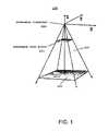
- FIG. 1is a graphical representation of the geometry for constructing a three-dimensional (3D) perspective viewing frustum, relative to an x, y, z coordinate system, in accordance with elastic presentation space graphics technology;
- FIG. 2is a graphical representation of the geometry of a presentation in accordance with elastic presentation space graphics technology
- FIG. 3is a block diagram illustrating a data processing system adapted for implementing an embodiment
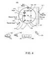
- FIG. 4a partial screen capture illustrating a GUI having lens control elements for user interaction with detail-in-context data presentations in accordance with an embodiment
- FIG. 5is a screen capture illustrating a presentation having two detail-in-context lenses and associated GUIs for defining the corners of a bounding rectangle GUI for cropping an original digital image or representation in accordance with an embodiment
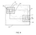
- FIG. 6is a screen capture illustrating a presentation having detail-in-context lenses, associated GUIs, and a bounding rectangle GUI or icon for cropping an original digital image or representation to produce a cropped image in accordance with an embodiment
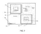
- FIG. 7is a screen capture illustrating a presentation having detail-in-context lenses and associated GUIs for selecting points between which to measure in an original digital image or representation in accordance with an embodiment
- FIG. 8is a screen capture illustrating a presentation having two detail-in-context lenses, associated GUIs, and a measuring tool GUI for displaying the measurement between selected points in an original digital image or representation in accordance with an embodiment
- FIG. 9is a screen capture illustrating a presentation having a single detail-in-context lens and associated GUI for defining the corners of a bounding rectangle GUI for cropping an original digital image or representation in accordance with an embodiment
- FIG. 10is a screen capture illustrating a presentation having a single detail-in-context lens, an associated GUI, and a bounding rectangle GUI or icon for cropping an original digital image or representation to produce a cropped image in accordance with an embodiment
- FIG. 11Ais a screen capture illustrating a presentation having a single detail-in-context lens and an associated GUI for selecting points between which to measure in an original digital image or representation in accordance with an embodiment
- FIG. 11Bis a screen capture illustrating a presentation having a single detail-in-context lens, an associated GUI, and a measuring tool GUI for displaying the measurement between two selected points in an original digital image or representation in accordance with an embodiment
- FIG. 11Cis a screen capture illustrating a presentation having a single detail-in-context lens, an associated GUI, and a measuring tool GUI for displaying the measurement between multiple selected points in an original digital image or representation in accordance with an embodiment
- FIG. 12is a flow chart illustrating a method for cropping a computer generated original image on a display in accordance with an embodiment
- FIG. 13is a flow chart illustrating a method for measuring within a computer generated original image on a display in accordance with an embodiment
- FIG. 14is a screen capture illustrating a detail-in-context presentation in which a lens is coupled to search results and is applied to an online map;
- FIG. 15is a screen capture illustrating an online map having cluttered data and labels
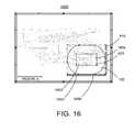
- FIG. 16is a screen capture illustrating a detail-in-context presentation of the online map of FIG. 15 in which de-cluttering is provided in the lens;
- FIG. 17is a flowchart illustrating operations of modules within the memory of a proxy server for providing a presentation of a region-of-interest within an original image to a client, the original image being stored in a content server coupled to the proxy server and the client over a network.
- data processing systemis used herein to refer to any machine for processing data, including the computer systems and network arrangements described herein.
- Conventional tools to address this probleminclude panning and zooming. While these tools are suitable for a large number of visual display applications, these tools become less effective where sections of the visual information are spatially related, such as in maps, three-dimensional representations, and newspapers, for example. In this type of information display, panning and zooming are not as effective as much of the context of the panned or zoomed display may be hidden.
- Detail-in-contextis the magnification of a particular region-of-interest (the “focal region” or “detail”) in a data presentation while preserving visibility of the surrounding information (the “context”).
- This techniquehas applicability to the display of large surface area media (e.g. digital maps) on computer screens of variable size including graphics workstations, laptop computers, personal digital assistants (“PDAs”), and cell phones.
- PDAspersonal digital assistants
- a representationis a formal system, or mapping, for specifying raw information or data that is stored in a computer or data processing system.
- a digital map of a cityis a representation of raw data including street names and the relative geographic location of streets and utilities. Such a representation may be displayed visually on a computer screen or printed on paper.
- a presentationis a spatial organization of a given representation that is appropriate for the task at hand.
- a presentation of a representationorganizes such things as the point of view and the relative emphasis of different parts or regions of the representation. For example, a digital map of a city may be presented with a region magnified to reveal street names.
- a detail-in-context presentationmay be considered as a distorted view (or distortion) of a portion of the original representation where the distortion is the result of the application of a “lens” like distortion function to the original representation.
- EPSElastic Presentation Space
- PDTPliable Display Technology
- detail-in-context data presentationsare characterized by magnification of areas of an image where detail is desired, in combination with compression of a restricted range of areas of the remaining information (i.e., the context), the result typically giving the appearance of a lens having been applied to the display surface.
- points in a representationare displaced in three dimensions and a perspective projection is used to display the points on a two-dimensional presentation display.
- the resulting presentationappears to be three-dimensional.
- the lens transformationappears to have stretched the continuous surface in a third dimension.
- EPS graphics technologya two-dimensional visual representation is placed onto a surface; this surface is placed in three-dimensional space; the surface, containing the representation, is viewed through perspective projection; and the surface is manipulated to effect the reorganization of image details.
- the presentation transformationis separated into two steps: surface manipulation or distortion and perspective projection.
- FIG. 1is a graphical representation 100 of the geometry for constructing a three-dimensional (“3D”) perspective viewing frustum 220 , relative to an x, y, z coordinate system, in accordance with elastic presentation space (EPS) graphics technology.
- EPSelastic presentation space
- 2Dtwo-dimensional
- EPSmagnification of regions of interest and the accompanying compression of the contextual region to accommodate this change in scale are produced by the movement of regions of the surface towards the viewpoint (“VP”) 240 located at the apex of the pyramidal shape 220 containing the frustum.
- the process of projecting these transformed layouts via a perspective projectionresults in a new 2D layout which includes the zoomed and compressed regions.
- the use of the third dimension and perspective distortion to provide magnification in EPSprovides a meaningful metaphor for the process of distorting the information presentation surface.
- the 3D manipulation of the information presentation surface in such a systemis an intermediate step in the process of creating a new 2D layout of the information.
- FIG. 2is a graphical representation 200 of the geometry of a presentation in accordance with EPS graphics technology.
- EPS graphics technologyemploys viewer-aligned perspective projections to produce detail-in-context presentations in a reference view plane 201 which may be viewed on a display.
- Undistorted 2D data pointsare located in a basal plane 210 of a 3D perspective viewing volume or frustum 220 which is defined by extreme rays 221 and 222 and the basal plane 210 .
- the VP 240is generally located above the centre point of the basal plane 210 and reference view plane (“RVP”) 201 . Points in the basal plane 210 are displaced upward onto a distorted surface 230 which is defined by a general 3D distortion function (i.e.
- the direction of the viewer-aligned perspective projection corresponding to the distorted surface 230is indicated by the line FPo-FP 231 drawn from a point FPo 232 in the basal plane 210 through the point FP 233 which corresponds to the focus or focal region or focal point of the distorted surface 230 .
- EPSis applicable to multidimensional data and is suited to implementation on a computer for dynamic detail-in-context display on an electronic display surface such as a monitor.
- EPSis typically characterized by magnification of areas of an image where detail is desired 233 , in combination with compression of a restricted range of areas of the remaining information (i.e. the context) 234 , the end result typically giving the appearance of a lens 230 having been applied to the display surface.
- the areas of the lens 230 where compression occursmay be referred to as the “shoulder” 234 of the lens 230 .
- the area of the representation transformed by the lensmay be referred to as the “lensed area”.
- the lensed areathus includes the focal region and the shoulder.
- the source image or representation to be viewedis located in the basal plane 210 .
- Magnification 233 and compression 234are achieved through elevating elements of the source image relative to the basal plane 210 , and then projecting the resultant distorted surface onto the reference view plane 201 .
- EPSperforms detail-in-context presentation of n-dimensional data through the use of a procedure wherein the data is mapped into a region in an (n+1) dimensional space, manipulated through perspective projections in the (n+1) dimensional space, and then finally transformed back into n-dimensional space for presentation.
- EPShas numerous advantages over conventional zoom, pan, and scroll technologies, including the capability of preserving the visibility of information outside 234 the local region of interest 233 .
- EPScan be implemented through the projection of an image onto a reference plane 201 in the following manner.
- the source image or representationis located on a basal plane 210 , and those regions of interest 233 of the image for which magnification is desired are elevated so as to move them closer to a reference plane situated between the reference viewpoint 240 and the reference view plane 201 .
- Magnification of the focal region 233 closest to the RVP 201varies inversely with distance from the RVP 201 . As shown in FIGS.
- compression of regions 234 outside the focal region 233is a function of both distance from the RVP 201 , and the gradient of the function describing the vertical distance from the RVP 201 with respect to horizontal distance from the focal region 233 .
- the resultant combination of magnification 233 and compression 234 of the image as seen from the reference viewpoint 240results in a lens-like effect similar to that of a magnifying glass applied to the image.
- the various functions used to vary the magnification and compression of the source image via vertical displacement from the basal plane 210are described as lenses, lens types, or lens functions. Lens functions that describe basic lens types with point and circular focal regions, as well as certain more complex lenses and advanced capabilities such as folding, examples of which are described by Carpendale.
- FIG. 3is a block diagram of a data processing system 300 adapted to implement an embodiment.
- the data processing systemis suitable for implementing EPS technology, for displaying detail-in-context presentations of representations, and for cropping representations in conjunction with a detail-in-context graphical user interface (“GUI”) 400 , as described below.
- the data processing system 300includes an input device 310 , a central processing unit or CPU 320 , memory 330 , a display 340 , and an interface 350 .
- the input device 310may include a keyboard, mouse, trackball, or similar device.
- the CPU 320may include dedicated coprocessors and memory devices.
- the memory 330may include RAM, ROM, databases, or disk devices.
- the display 340may include a computer screen, terminal device, or a hardcopy producing output device such as a printer or plotter.
- the interface 350may include an interface to the Internet and/or to another wired or wireless network (not shown).
- the data processing system 300may be linked to other data processing systems (not shown) by a network (not shown) through the interface 350 .
- the data processing system 300may be a client and/or server in a client/server system.
- the data processing system 300has stored therein data representing sequences of instructions which when executed cause the method described herein to be performed.
- the data processing system 300may contain additional software and hardware.
- detail-in-context presentations of data using techniques such as pliable surfaces, as described by Carpendale,are useful in presenting large amounts of information on limited-size display surfaces.
- Detail-in-context viewsallow magnification of a particular region-of-interest (the “focal region”) 233 in a data presentation while preserving visibility of the surrounding information 210 .
- a GUI 400is described having lens control elements that can be implemented in software and applied to the cropping and measurement of representations and to the control of detail-in-context data presentations.
- the softwarecan be loaded into and run by the data processing system 300 of FIG. 3 .
- FIG. 4is a partial screen capture illustrating a GUI 400 having lens control elements for user interaction with detail-in-context data presentations in accordance with an embodiment.
- Detail-in-context data presentationsare characterized by magnification of areas of an image where detail is desired, in combination with compression of a restricted range of areas of the remaining information (i.e. the context), the end result typically giving the appearance of a lens having been applied to the display screen surface.
- This lens 410includes a “focal region” 420 having high magnification, a surrounding “shoulder region” 430 where information is typically visibly compressed, and a “base” 412 surrounding the shoulder region 430 and defining the extent of the lens 410 .
- FIG. 4is a partial screen capture illustrating a GUI 400 having lens control elements for user interaction with detail-in-context data presentations in accordance with an embodiment.
- Detail-in-context data presentationsare characterized by magnification of areas of an image where detail is desired, in combination with compression of a restricted range of areas of
- the lens 410is shown with a circular shaped base 412 (or outline) and with a focal region 420 lying near the center of the lens 410 .
- the lens 410 and focal region 420may have any desired shape.
- the lenses 510 , 511have a pyramid shape with flat tops 520 , 521 and trapezoidal shoulders 530 , 531 .
- the base of the lens 412may be coextensive with the focal region 420 .
- the GUI 400has lens control elements that, in combination, provide for the interactive control of the lens 410 , 510 , 511 .
- the effective control of the characteristics of the lens 410 by a useri.e. dynamic interaction with a detail-in-context lens
- one or more of these lens control elementsmay be made visible to the user on the display surface 340 by appearing as overlay icons on the lens 410 .
- Interaction with each elementis performed via the motion of an input or pointing device 310 (e.g. mouse), with the motion resulting in an appropriate change in the corresponding lens characteristic.
- selection of which lens control element is actively controlled by the motion of the pointing device 310 at any given timeis determined by the proximity of the icon representing the pointing device 310 (e.g. cursor) on the display surface 340 to the appropriate component of the lens 410 .
- the icon representing the pointing device 310e.g. cursor
- “dragging” of the pointing device at the periphery of the bounding rectangle of the lens base 412causes a corresponding change in the size of the lens 410 (i.e. “resizing”).
- the GUI 400provides the user with a visual representation of which lens control element is being adjusted through the display of one or more corresponding icons.
- a mouse 310controls the position of a cursor icon 401 that is displayed on the display screen 340 .
- the cursor 401is moved by moving the mouse 310 over a flat surface, such as the top of a desk, in the desired direction of movement of the cursor 401 .
- a flat surfacesuch as the top of a desk
- the two-dimensional movement of the mouse 310 on the flat surfacetranslates into a corresponding two-dimensional movement of the cursor 401 on the display screen 340 .
- a mouse 310typically has one or more finger actuated control buttons (i.e. mouse buttons). While the mouse buttons can be used for different functions such as selecting a menu option pointed at by the cursor 401 , a single mouse button may also be used to “select” a lens 410 and to trace the movement of the cursor 401 along a desired path. Specifically, to select a lens 410 , the cursor 401 is first located within the extent of the lens 410 . In other words, the cursor 401 is “pointed” at the lens 410 . Next, the mouse button is depressed and released. That is, the mouse button is “clicked”. Selection is thus a point and click operation.
- the mouse buttonscan be used for different functions such as selecting a menu option pointed at by the cursor 401
- a single mouse buttonmay also be used to “select” a lens 410 and to trace the movement of the cursor 401 along a desired path.
- the cursor 401is first located within the extent of the lens
- the cursor 401is located at the desired starting location, the mouse button is depressed to signal the computer 320 to activate a lens control element, and the mouse 310 is moved while maintaining the button depressed. After the desired path has been traced, the mouse button is released.
- This procedureis often referred to as “clicking” and “dragging” (i.e. a click and drag operation). It will be understood that a predetermined key on a keyboard 310 could also be used to activate a mouse click or drag.
- clickingwill refer to the depression of a mouse button indicating a selection by the user and the term “dragging” will refer to the subsequent motion of the mouse 310 and cursor 401 without the release of the mouse button.
- the GUI 400may include the following lens control elements: move, pickup, resize base, resize focus, fold, magnify, and scoop. Each of these lens control elements has at least one lens control icon or alternate cursor icon associated with it.
- the following lens control iconsmay be displayed over the lens 410 : pickup icon 450 , base outline icon 412 , base bounding rectangle icon 411 , focal region bounding rectangle icon 421 , handle icons 481 , 482 , 491 , magnify slide bar icon 440 , and scoop slide bar icon 540 (see FIG. 5 ).
- these iconsare displayed simultaneously after selection of the lens 410 .
- an alternate cursor icon 460 , 470 , 480 , 490may be displayed over the lens 410 to replace the cursor 401 or may be displayed in combination with the cursor 401 .
- bounding rectangle icons 411 , 421are displayed surrounding the base 412 and focal region 420 of the selected lens 410 to indicate that the lens 410 has been selected.
- bounding rectangles 411 , 421one might view them as glass windows enclosing the lens base 412 and focal region 420 , respectively.
- the bounding rectangles 411 , 421include handle icons 481 , 482 , 491 allowing for direct manipulation of the enclosed base 412 and focal region 420 as will be explained below.
- the bounding rectangles 411 , 421not only inform the user that the lens 410 has been selected, but also provide the user with indications as to what manipulation operations might be possible for the selected lens 410 though use of the displayed handles 481 , 482 , 491 .
- a bounding region having a shape other than generally rectangularmay also be provided, such a bounding region of any of a great number of shapes including oblong, oval, ovoid, conical, cubic, cylindrical, polyhedral, spherical, etc.
- the cursor 401provides a visual cue indicating the nature of an available lens control element. As such, the cursor 401 will generally change in form by simply pointing to a different lens control icon 450 , 412 , 411 , 421 , 481 , 482 , 491 , 440 , 540 . For example, when resizing the base 412 of a lens 410 using a corner handle 491 , the cursor 401 will change form to a resize icon 490 once it is pointed at (i.e. positioned over) the corner handle 491 . The cursor 401 will remain in the form of the resize icon 490 until the cursor 401 has been moved away from the corner handle 491 .
- Lateral movement of a lens 410is provided by the move lens control element of the GUI 400 .
- This functionalityis accomplished by the user first selecting the lens 410 , 510 , 511 through a point and click operation. Then, the user points to a point within the lens 410 that is other than a point lying on a lens control icon 450 , 412 , 411 , 421 , 481 , 482 , 491 , 440 , 540 .
- a move icon 460is displayed over the lens 410 to replace the cursor 401 or may be displayed in combination with the cursor 401 .
- the move icon 460not only informs the user that the lens 410 may be moved, but also provides the user with indications as to what movement operations are possible for the selected lens 410 .
- the move icon 460may include arrowheads indicating up, down, left, and right motion.
- the lens 410is moved by a click and drag operation in which the user clicks and drags the lens 410 to the desired position on the screen 340 and then releases the mouse button 310 .
- the lens 410is locked in its new position until a further pickup and move operation is performed.
- Lateral movement of a lens 410is also provided by the pickup lens control element of the GUI. This functionality is accomplished by the user first selecting the lens 410 through a point and click operation. As mentioned above, when the lens 410 is selected a pickup icon 450 is displayed over the lens 410 near the centre of the lens 410 . Typically, the pickup icon 450 will be a crosshairs. In addition, a base outline 412 is displayed over the lens 410 representing the base 412 of the lens 410 . The crosshairs 450 and lens outline 412 not only inform the user that the lens has been selected, but also provides the user with an indication as to the pickup operation that is possible for the selected lens 410 . Next, the user points at the crosshairs 450 with the cursor 401 .
- the lens outline 412is moved by a click and drag operation in which the user clicks and drags the crosshairs 450 to the desired position on the screen 340 and then releases the mouse button 310 .
- the full lens 410is then moved to the new position and is locked there until a further pickup operation is performed.
- Resizing of the base 412 (or outline) of a lens 410is provided by the resize base lens control element of the GUI. After the lens 410 is selected, a bounding rectangle icon 411 is displayed surrounding the base 412 .
- the bounding rectangle 411includes handles 491 . These handles 491 can be used to stretch the base 412 taller or shorter, wider or narrower, or proportionally larger or smaller.
- the corner handles 491will keep the proportions the same while changing the size.
- the middle handles(not shown) will make the base 412 taller or shorter, wider or narrower. Resizing the base 412 by the corner handles 491 will keep the base 412 in proportion. Resizing the base 412 by the middle handles (not shown) will change the proportions of the base 412 .
- the middle handleschange the aspect ratio of the base 412 (i.e. the ratio between the height and the width of the bounding rectangle 411 of the base 412 ).
- a resize icon 490may be displayed over the handle 491 to replace the cursor 401 or may be displayed in combination with the cursor 401 .
- the resize icon 490not only informs the user that the handle 491 may be selected, but also provides the user with indications as to the resizing operations that are possible with the selected handle.
- the resize icon 490 for a corner handle 491may include arrows indicating proportional resizing.
- the resize icon (not shown) for a middle handlemay include arrows indicating width resizing or height resizing.
- Resizing of the focal region 420 of a lens 410is provided by the resize focus lens control element of the GUI.
- a bounding rectangle icon 421is displayed surrounding the focal region 420 .
- the bounding rectangle 421includes handles 481 , 482 . These handles 481 , 482 can be used to stretch the focal region 420 taller or shorter, wider or narrower, or proportionally larger or smaller.
- the corner handles 481will keep the proportions the same while changing the size.
- the middle handles 482will make the focal region 420 taller or shorter, wider or narrower. Resizing the focal region 420 by the corner handles 481 will keep the focal region 420 in proportion.
- the middle handles 482will change the proportions of the focal region 420 . That is, the middle handles 482 change the aspect ratio of the focal region 420 (i.e. the ratio between the height and the width of the bounding rectangle 421 of the focal region 420 ).
- a resize icon 480may be displayed over the handle 481 , 482 to replace the cursor 401 or may be displayed in combination with the cursor 401 .
- the resize icon 480not only informs the user that a handle 481 , 482 may be selected, but also provides the user with indications as to the resizing operations that are possible with the selected handle.
- the resize icon 480 for a corner handle 481may include arrows indicating proportional resizing.
- the resize icon 480 for a middle handle 482may include arrows indicating width resizing or height resizing.
- Folding of the focal region 420 of a lens 410is provided by the fold control element of the GUI.
- control of the degree and direction of foldingi.e. skewing of the viewer aligned vector 231 as described by Carpendale
- the direction of foldingis determined by the direction in which the point 471 is dragged.
- the degree of foldingis determined by the magnitude of the translation of the cursor 401 during the drag.
- the direction and degree of foldingcorresponds to the relative displacement of the focus 420 with respect to the lens base 410 . In other words, and referring to FIG.
- the direction and degree of foldingcorresponds to the displacement of the point FP 233 relative to the point FPo 232 , where the vector joining the points FPo 232 and FP 233 defines the viewer aligned vector 231 .
- a bounding rectangle icon 421is displayed surrounding the focal region 420 .
- the bounding rectangle 421includes handles 481 , 482 .
- a fold icon 470may be displayed over the point 471 to replace the cursor 401 or may be displayed in combination with the cursor 401 .
- the fold icon 470not only informs the user that a point 471 on the bounding rectangle 421 may be selected, but also provides the user with indications as to what fold operations are possible.
- the fold icon 470may include arrowheads indicating up, down, left, and right motion.
- Magnification of the lens 410is provided by the magnify lens control element of the GUI.
- the magnify controlis presented to the user as a slide bar icon 440 near or adjacent to the lens 410 and typically to one side of the lens 410 .
- Sliding the bar 441 of the slide bar 440results in a proportional change in the magnification of the lens 410 .
- the slide bar 440not only informs the user that magnification of the lens 410 may be selected, but also provides the user with an indication as to what level of magnification is possible.
- the slide bar 440includes a bar 441 that may be slid up and down, or left and right, to adjust and indicate the level of magnification.
- the userwould click on the bar 441 of the slide bar 440 and drag in the direction of desired magnification level. Once the desired level of magnification is reached, the user would release the mouse button 310 .
- the lens 410is then locked with the selected magnification until a further magnification operation is performed.
- the focal region 420is an area of the lens 410 having constant magnification (i.e. if the focal region is a plane). Again referring to FIGS. 1 and 2 , magnification of the focal region 420 , 233 varies inversely with the distance from the focal region 420 , 233 to the reference view plane (RVP) 201 .
- RVPreference view plane
- Magnification of areas lying in the shoulder region 430 of the lens 410also varies inversely with their distance from the RVP 201 .
- magnification of areas lying in the shoulder region 430will range from unity at the base 412 to the level of magnification of the focal region 420 .
- Zoom functionalityis provided by the zoom lens control element of the GUI.
- the zoom lens control elementallows a user to quickly navigate to a region of interest 233 within a continuous view of a larger presentation 210 and then zoom in to that region of interest 233 for detailed viewing or editing.
- the combined presentation area covered by the focal region 420 and shoulder region 430 and surrounded by the base 412may be referred to as the “extent of the lens.”
- the presentation area covered by the focal region 420may be referred to as the “extent of the focal region.”
- the extent of the lensmay be indicated to a user by a base bounding rectangle 411 when the lens 410 is selected.
- the extent of the lensmay also be indicated by an arbitrarily shaped figure that bounds or is coincident with the perimeter of the base 412 .
- the extent of the focal regionmay be indicated by a second bounding rectangle 421 or arbitrarily shaped figure.
- the zoom lens control elementallows a user to: (a) “zoom in” to the extent of the focal region such that the extent of the focal region fills the display screen 340 (i.e., “zoom to focal region extent”); (b) “zoom in” to the extent of the lens such that the extent of the lens fills the display screen 340 (i.e., “zoom to lens extent”); or, (c) “zoom in” to the area lying outside of the extent of the focal region such that the area without the focal region is magnified to the same level as the extent of the focal region (i.e., “zoom to scale”).
- zoom functionalityis accomplished by the user first selecting the zoom icon 495 through a point and click operation.
- a zoom cursor icon 496may be displayed to replace the cursor 401 or may be displayed in combination with the cursor 401 .
- the zoom cursor icon 496provides the user with indications as to what zoom operations are possible.
- the zoom cursor icon 496may include a magnifying glass.
- zoom to focal region extentsuch that the extent of the focal region fills the display screen 340
- zoom to lens extentTo zoom in to the extent of the lens such that the extent of the lens fills the display screen 340 (i.e., “zoom to lens extent”), the user would point and click within the extent of the lens.
- zoom in to the presentation area without the extent of the focal regionsuch that the area without the extent of the focal region is magnified to the same level as the extent of the focal region (i.e., “zoom to scale”), the user would point and click without the extent of the lens.
- the presentationis locked with the selected zoom until a further zoom operation is performed.
- a zoom function menu with multiple items (not shown) or multiple zoom function icons (not shown)may be used for zoom function selection.
- the zoom function menumay be presented as a pull-down menu.
- the zoom function iconsmay be presented in a toolbar or adjacent to the lens 410 when the lens is selected.
- Individual zoom function menu items or zoom function iconsmay be provided for each of the “zoom to focal region extent”, “zoom to lens extent”, and “zoom to scale” functions described above.
- a bounding rectangle icon 411may be displayed surrounding the base 412 and a bounding rectangle icon 421 may be displayed surrounding the focal region 420 .
- Zoom functionalityis accomplished by the user selecting a zoom function from the zoom function menu or via the zoom function icons using a point and click operation. In this way, a zoom function may be selected without considering the position of the cursor 401 within the lens 410 .
- the concavity or “scoop” of the shoulder region 430 of the lens 410is provided by the scoop lens control element of the GUI.
- the scoop controlis presented to the user as a slide bar icon 540 (see FIG. 5 ) near or adjacent to the lens 410 , 510 , 511 and typically below the lens 410 . Sliding the bar 541 of the slide bar 540 results in a proportional change in the concavity or scoop of the shoulder region 430 of the lens 410 .
- the slide bar 540not only informs the user that the shape of the shoulder region 430 of the lens 410 may be selected, but also provides the user with an indication as to what degree of shaping is possible.
- the slide bar 540includes a bar 541 that may be slid left and right, or up and down, to adjust and indicate the degree of scooping.
- the userwould click on the bar 541 of the slide bar 540 and drag in the direction of desired scooping degree. Once the desired degree of scooping is reached, the user would release the mouse button 310 . The lens 410 is then locked with the selected scoop until a further scooping operation is performed.
- a usermay choose to hide one or more lens control icons 450 , 412 , 411 , 421 , 481 , 482 , 491 , 440 , 540 shown in FIGS. 4 and 5 from view so as not to impede the user's view of the image within the lens 410 . This may be helpful, for example, during a move operation. A user may select this option through a variety of different ways, such as a menu or lens property dialog box.
- GUI 400maintains a record of control element operations such that the user may restore pre-operation presentations.
- This record of operationsmay be accessed by or presented to the user through “Undo” and “Redo” icons 497 , 498 , through a pull-down operation history menu (not shown), or through a toolbar.
- detail-in-context data viewing techniquesallow a user to view multiple levels of detail or resolution on one display 340 .
- the appearance of the data display or presentationis that of one or more virtual lenses showing detail 233 within the context of a larger area view 210 .
- Using multiple lenses in detail-in-context data presentationsmay be used to compare two regions of interest at the same time. Folding enhances this comparison by allowing the user to pull the regions of interest closer together.
- detail-in-context technologysuch as PDT
- an area of interestcan be magnified to pixel level resolution, or to any level of detail available from the source information, for in-depth review.
- the digital imagesmay include graphic images, maps, photographic images, or text documents, and the source information may be in raster, vector, or text form.
- a usercan define a lens 410 over the object using the GUI 400 .
- the lens 410may be introduced to the original image to form a presentation through the use of a pull-down menu selection, tool bar icon, etc.
- lens control elements for the GUI 400such as move, pickup, resize base, resize focus, fold, magnify, zoom, and scoop, as described above, the user adjusts the lens 410 for detailed viewing of the object or area.
- the magnify lens control elementfor example, the user may magnify the focal region 420 of the lens 410 to pixel quality resolution revealing detailed information pertaining to the selected object or area.
- a base imagei.e., the image outside the extent of the lens
- a lens imagei.e., the image within the extent of the lens
- the data processing system 300employs EPS techniques with an input device 310 and GUI 400 for selecting objects or areas for detailed display to a user on a display screen 340 .
- Data representing an original image or representationis received by the CPU 320 of the data processing system 300 .
- the CPU 320processes the data in accordance with instructions received from the user via an input device 310 and GUI 400 to produce a detail-in-context presentation. The presentation is presented to the user on a display screen 340 . It will be understood that the CPU 320 may apply a transformation to the shoulder region 430 surrounding the region-of-interest 420 to affect blending or folding in accordance with EPS technology.
- the transformationmay map the region-of-interest 420 and/or shoulder region 430 to a predefined lens surface, defined by a transformation or distortion function and having a variety of shapes, using EPS techniques.
- the lens 410may be simply coextensive with the region-of-interest 420 .
- the lens control elements of the GUI 400are adjusted by the user via an input device 310 to control the characteristics of the lens 410 in the detail-in-context presentation.
- an input device 310such as a mouse
- a useradjusts parameters of the lens 410 using icons and scroll bars of the GUI 400 that are displayed over the lens 410 on the display screen 340 .
- the usermay also adjust parameters of the image of the full scene.
- Signals representing input device 310 movements and selectionsare transmitted to the CPU 320 of the data processing system 300 where they are translated into instructions for lens control.
- the lens 410may be added to the presentation before or after the object or area is selected. That is, the user may first add a lens 410 to a presentation or the user may move a preexisting lens into place over the selected object or area.
- the lens 410may be introduced to the original image to form the presentation through the use of a pull-down menu selection, tool bar icon, etc.
- a usercan view a large area (i.e., outside the extent 412 of the lens 410 ) while focusing in on a smaller area (or within the focal region 420 of the lens 410 ) surrounding the selected object. This makes it possible for a user to accurately gather detailed information without losing visibility or context of the portion of the original image surrounding the selected object.
- Detail-in-context data viewing techniquesallow a user to view multiple levels of detail or resolution on one display 340 .
- the appearance of the data display or presentationis that of one or more virtual lens showing detail 233 within the context of a larger area view 210 .
- Using multiple lenses in detail-in-context data presentationsmay be used to compare two regions of interest at the same time. Folding enhances this comparison by allowing the user to pull the regions of interest closer together.
- multiple detail-in-context lensesmay be used to accurately crop digital images.
- FIG. 5is a screen capture illustrating a presentation 500 having two detail-in-context lenses 510 , 511 and associated GUIs 501 , 502 for defining the corners of a bounding rectangle GUI for cropping an original digital image or representation in accordance with an embodiment.
- the original image to be croppedis a map of North America.
- a userdefines a first lens 510 over Washington State using a first GUI 501 and a second lens 511 over Florida using a second GUI 502 .
- the lenses 510 , 511may be introduced to the original image to form the illustrated presentation through the use of a pull-down menu selection, tool bar icon, etc.
- the lenses 510 , 511are positioned at what will be the top left and bottom right corners of a bounding rectangle that will be used to define the cropped image.
- lens control elements for each GUI 501 , 502such as move, pickup, resize base, resize focus, fold, and magnify as described above, the user adjusts each lens 510 , 511 to accurately select a point or corner for the creation of a bounding rectangle for cropping.
- Each selected pointmay be indicated on in the presentation with a crosshairs icon 450 , for example.
- the usermay magnify the focal region 520 , 521 of each lens 510 , 511 to pixel quality resolution making it easy to view, for example, the point where the boarders of Washington State and Canada meet in the first lens 510 and the point where land ends at the coast of Florida in the second lens 511 .
- FIG. 6is a screen capture illustrating a presentation 600 having detail-in-context lenses 510 , 511 , associated GUIs 501 , 502 , and a bounding rectangle GUI or icon 610 for cropping an original digital image or representation to produce a cropped image 640 in accordance with an embodiment.
- the usermay use an existing tool to crop the presentation 600 to produce a cropped image 640 .
- the userhas defined an area with a bounding rectangle GUI 610 .
- the bounding rectangle GUI 610defining an area for the cropped image 640 , may also be displaced or distorted by the lenses 510 , 511 , however, in FIG. 6 , this is not shown.
- the resultant cropped image 640may be presented with or without lens distortions 510 , 511 .
- the data processing system 300employs EPS techniques with an input device 310 and GUIs 501 , 502 , 610 for selecting points 620 , 630 to define a cropped image 640 for display to a user on a display screen 340 .
- Data representing an original image or representationis received by the CPU 320 of the data processing system 300 .
- the CPU 320processes the data in accordance with instructions received from the user via an input device 310 and GUIs 501 , 502 to produce a detail-in-context presentation 500 .
- the presentation 500is presented to the user on a display screen 340 .
- the CPU 320may apply a transformation to the shoulder regions 530 , 531 surrounding the regions-of-interest 520 , 521 to affect blending or folding in accordance with EPS technology.
- the transformationmay map the regions-of-interest 520 , 521 and/or shoulder regions 530 , 531 to a predefined lens surface, defined by a transformation or distortion function and having a variety of shapes, using EPS techniques.
- the lens 510 , 511may be simply coextensive with the regions-of-interest 520 , 521 . Blending and folding of lenses in detail-in-context presentations are described in United States Patent Application Publication No. 2002/0044154 which is incorporated herein by reference.
- the lens control elements of the GUIs 501 , 502are adjusted by the user via an input device 310 to control the characteristics of the lenses 510 , 511 in the detail-in-context presentation 500 .
- an input device 310such as a mouse
- a useradjusts parameters of the lens 510 , 511 using icons and scroll bars of GUIs 501 , 502 that are displayed over the lens on the display screen 340 .
- the usermay also adjust parameters of the image of the full scene 500 .
- Signals representing input device 310 movements and selectionsare transmitted to the CPU 320 of the data processing system 300 where they are translated into instructions for lens control.
- the bounding rectangle GUI 610indicates the selected area for the cropped image 640 .
- the usercan change the location of the corners 620 , 630 (or regions-of-interest 520 , 521 ) in the presentation 600 .
- the bounding rectangle GUI 610may be presented automatically upon placement of the lenses 510 , 511 or its presentation may be selected using a pull-down menu selection, tool bar, crop icon, etc.
- the usercan decide whether or not the currently cropped image 640 accurately captures the desired area of the presentation 600 . If the user is satisfied with the cropped image 640 , the user may select the cropped image 640 by double clicking within the bounding rectangle GUI 610 or with a pull-down menu selection, crop icon, crop button, etc. The current cropped image 640 is thus selected for further processing, such as inclusion into a document being concurrently displayed in another window or replacement of the original presentation with the cropped image 640 . Clicking on one of the corners 620 , 630 will select the corresponding lens 510 , 511 and GUI 501 , 502 for adjustment. If the user is dissatisfied with the current cropped image 640 , then the double clicking operation is avoided and instead a corner 620 , 630 of the bounding rectangle GUI 610 can be moved to show a different cropped image 640 .
- a usercan view a large area 600 (i.e. outside the lenses 510 , 511 ) while focusing in on smaller areas 520 , 521 (i.e. inside the focal regions 520 , 521 of the lenses 510 , 511 ) surrounding the selected points 620 , 630 .
- Thismakes it possible for a user to perform accurate cropping without losing visibility or context of the portion of the original image surrounding the cropped area 640 .
- two lenses 510 , 511are added to the presentation 500 before the bounding rectangle GUI 610 is activated.
- the lenses 510 , 511 and bounding rectangle GUI 610can be combined. That is, the user may first add a lens 510 to a presentation 500 or the user may move a pre-existing lens into place at, say, the top left corner point 620 in FIG. 6 . At this stage, before the second point 630 is selected, the bounding rectangle GUI 610 is activated. Now, to select the second point 630 , the bottom right corner 650 of the bounding rectangle GUI 610 is moved (e.g. with a click and drag operation) by the user. As the bottom right corner 650 of the bounding rectangle GUI 610 is dragged, the second lens 511 is presented over and moves with the corner 650 . This facilitates the accurate selection of the second point 630 for defining the cropped image 640 .
- the userfirst moves the mouse 310 to position a cursor 401 and depresses a mouse pushbutton to designate the first point or corner 620 of the desired cropped image 640 .
- a first lens 510is presented at this point.
- the location 620 of this first lens 510 or its characteristicsmay be adjusted as described above.
- the bounding rectangle GUI 610is now activated by selecting from a pull-down menu for example.
- the first lens 510is clicked and dragged to present the bounding rectangle GUI 610 .
- the cursor's new position on the display 340defines the second point or corner 630 diagonally opposite the first corner 620 .
- the second lens 511is presented over the second corner 630 during the click and draft operation.
- a sequentially varying bounding rectangle GUI 610 for the potential cropped image 640is displayed. If the user is satisfied with the cropped image 640 , the user releases the mouse pushbutton to complete the click and drag operation.
- the useris then presented with a bounding rectangle GUI 610 with lens 510 , 511 at opposite corners 620 , 630 . The user may then choose to complete the crop as described above (e.g. by double clicking within the bounding rectangle GUI 610 ).
- the bounding rectangle GUI 610may have a shape other than rectangular.
- a polygonal shaped bounding GUImay be defined with three or more lens.
- the outline of the bounding GUImay pass through each lens.
- a lensis placed at each selected point or corner.
- a lensmay be presented over the end of the crop line (i.e. over the cursor's position). In other words, the end of the crop line is attached to a lens that moves with the crop line end as it is repositioned by a user.
- a lensmay be left at each point or corner of the bounding polygon GUI with this alternative as well.
- a lensmay be moved along the path of the bounding rectangle or polygon to allow a user to inspect the entire perimeter of the bounding rectangle or polygon.
- a usermay accurately select each of the points along the perimeter of the bounding rectangle or polygon rather that just corners or line segment end points. In so doing, a more accurate cropped image 640 may be produced.
- FIG. 7is a screen capture illustrating a presentation 700 having detail-in-context lenses 710 , 711 and associated GUIs 701 , 702 for selecting points between which to measure in an original digital image or representation in accordance with an embodiment.
- a userTo make a measurement between two points in an original digital image, a user first adds detail-in-context lenses 710 , 711 to the original image to create a detail-in-context presentation 700 .
- the lens 710 , 711enable the user to view high resolution data in the focus of each lens.
- the lensesare positioned over selected points 750 , 760 and configured as described above.
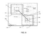
- FIG. 8is a screen capture illustrating a presentation 800 having two detail-in-context lenses 710 , 711 , associated GUIs 701 , 702 , and a measuring tool GUI 810 , 820 for displaying the measurement between selected points 750 , 760 in an original digital image or representation in accordance with an embodiment.
- the usermay select a measuring tool to determine the distance between the points 750 , 760 .
- the measuring toolmay be selected using a pull-down menu selection, tool bar, etc.
- the measuring toolmay present a measuring tool GUI which may include a measured value icon 820 for displaying the measured value or distance between the selected points 750 , 760 and a line segment icon 810 for displaying the measurement path between the selected points 750 , 760 to a user.
- a measured value icon 820for displaying the measured value or distance between the selected points 750 , 760
- a line segment icon 810for displaying the measurement path between the selected points 750 , 760 to a user.
- the selected points 750 , 760are contained within the focal region of each lens 710 , 711 which may be displayed at a higher resolution that the surrounding presentation 800 , the measured value may be determined more accurately.
- the distance between Terrace and Victoriahas a measure value 820 of 734, 771 meters.
- two lenses 710 , 711are added to the presentation 700 , 800 before the measuring tool GUI 810 , 820 is activated.
- the lenses 710 , 711 and measuring tool GUI 810 , 820can be combined. That is, the user may first add a lens 710 to a presentation 800 or the user may move a pre-existing lens into place at, say, the Terrace point 750 in FIG. 8 . At this stage, before the Victoria point 760 is selected, the measuring tool GUI 810 , 820 is activated.
- the end point 830 of the line segment icon 810i.e., the point over the cursor's position
- the second lens 711is presented over and moves with the end point 830 .
- Thisfacilitates the accurate selection of the second point 760 for defining the distance to be measured (i.e. the line segment between points 750 , 760 ).
- a new lensmay be added to the presentation.
- the lensmay be a carrier for the cropping or measurement tool, or the lens may be the tool itself. In both the single lens and multiple lenses embodiments, accuracy of cropping and measurement may be improved.
- FIG. 9is a screen capture illustrating a presentation 900 having a single detail-in-context lens 910 and associated GUI 901 for defining the corners of a bounding rectangle GUI for cropping an original digital image or representation in accordance with an embodiment.
- a scale icon 940may be included in the presentation 900 .
- the userfirst selects the cropping tool (which is associated with a lens 910 ) using a pull-down menu selection, tool bar, etc., and then selects a starting or first point 920 using a point and click operation. This places a lens 910 and an associated GUI 901 over the first point 920 .
- FIG. 10is a screen capture illustrating a presentation 1000 having a single detail-in-context lens 910 , an associated GUI 901 , and a bounding rectangle GUI or icon 1010 for cropping an original digital image or representation to produce a cropped image 1040 in accordance with an embodiment.
- the bounding rectangle GUI 1010may be dynamically presented as the lens 910 is dragged diagonally from the first point 920 to the second point 930 .
- the bounding rectangle GUI 1010defines the area of the cropped image 1040 .
- the bounding rectangle GUI 1010may be drawn by first activating the tool (e.g., tool bar, etc.), followed by a point and click operation to locate the first point or corner 920 , while maintaining a depressed mouse selection button, a drag operation during which the lens 910 is presented over the end of the crop line 950 (i.e., over the cursor's position, that is, the end of the crop line 950 is attached to the lens 910 which moves with the crop line end 950 as it is repositioned by a user), and a mouse selection button release to select the second point or corner 930 .
- the bounding rectangle GUI 1010is dynamically presented as the end of the crop line 950 is moved by the user.
- the bounding rectangle GUI 1010may have a shape other than rectangular.
- a polygonal shaped bounding GUImay be defined with three or more lens.
- the outline of the bounding GUImay pass through each lens.
- the polygonal shaped bounding GUImay be drawn, say, through an activation step, followed by a point and click to locate the first point, a series of click and drag operations to chose each subsequent point of the polygon, and ending with a double click operation that leaves a lens placed over the last selected point or corner.
- a lensmay be presented over the end of the crop line (i.e. over the cursor's position). In other words, the end of the crop line is attached to a lens that moves with the crop line end as it is repositioned by a user.
- an alternate cursor iconmay be displayed over the presentation 900 , 1000 to replace the cursor 401 or may be displayed in combination with the cursor 401 .
- the alternate cursor iconmay be a lens 910 , a cropping cursor icon (not shown), or a combination lens 910 and cropping cursor icon.
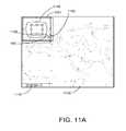
- FIG. 11Ais a screen capture illustrating a presentation 1100 having a single detail-in-context lens 1110 and an associated GUI 1101 for selecting points between which to measure in an original digital image or representation in accordance with an embodiment.
- FIG. 11Bis a screen capture illustrating a presentation 1100 having a single detail-in-context lens 1110 , an associated GUI 1101 , and a measuring tool GUI 1140 , 1141 , for displaying the measurement between selected points 1120 , 1130 in an original digital image or representation in accordance with an embodiment.
- FIG. 11Ais a screen capture illustrating a presentation 1100 having a single detail-in-context lens 1110 and an associated GUI 1101 for selecting points between which to measure in an original digital image or representation in accordance with an embodiment.
- FIG. 11Bis a screen capture illustrating a presentation 1100 having a single detail-in-context lens 1110 , an associated GUI 1101 , and a measuring tool GUI 1140 , 1141 , for displaying the
- 11Cis a screen capture illustrating a presentation 1100 having a single detail-in-context lens 1110 , an associated GUI 1101 , and a measuring tool GUI 1140 , 1142 , 1142 , 1143 for displaying the measurement between selected points 1120 , 1130 , 1160 in an original digital image or representation in accordance with an embodiment.
- the userTo make a measurement in the original image 1100 , the user first selects the measuring tool (which is associated with a lens 1110 ) using a pull-down menu selection, tool bar, etc., and then selects a starting or first point 1120 using a point and click operation. This places a lens 1110 and an associated GUI 1101 over the first point 1120 as shown in FIG. 11A .
- a measuring tool icon 1180may also be displayed over the first point 1120 as mentioned above.
- the lens 1110enables the user to view high resolution data in its focus.
- the userdrags the lens 1110 to select a second point 1130 for the measurement as shown in FIG. 11B .
- the measuring toolmay present a measuring tool GUI which may include a measured value icon 1141 for displaying the measured value or distance between the selected points 1120 , 1130 and a line segment icon 1140 for displaying the measurement path between the selected points 1120 , 1130 as shown in FIG. 11B .
- the measuring tool GUI 1140 , 1141may be dynamically presented as the lens 1110 is dragged from the first point 1120 to the second point 1130 .
- a usermay make linked measurements in one or more operations.
- Linked line segment icons 1140 , 1142may be drawn, say, through an activation step, followed by a point and click to locate the first point 1120 , a series of click and drag operations to chose each subsequent point 1130 , 1160 of the linked line segment, and ending with a double click operation that leaves a lens 1110 placed over the last selected point 1160 .
- a lens 1110may be presented over the end of the line segment 1150 (i.e. over the cursor's position). In other words, the end of the line segment 1150 is attached to a lens 1110 that moves with the end of the line segment 1150 as it is repositioned by a user.
- a scale icon 1170may be included in the presentation 1100 .
- an alternate cursor iconmay be displayed over the presentation 1100 to replace the cursor 401 or may be displayed in combination with the cursor 401 .
- the alternate cursor iconmay be a lens 1110 , a measuring cursor icon 1180 , or a combination lens 1110 and measuring cursor icon 1180 .
- the line segment icon 1140may be presented as an exclusive OR (XOR) with the underlying portion of the original or background image 1100 .
- FIG. 12is a flow chart 1200 illustrating a method for cropping a computer generated original image on a display 340 in accordance with an embodiment. At block 1201 , the method starts.
- a user-selected movable boundary 610 , 1010 on the original imageis adjusted to define a cropped image 640 , 1040 within the boundary, the boundary being defined by two or more points 620 , 630 , 920 , 930 on the original image.
- a lens surface 510 , 511 , 910is created for one or more of the regions surrounding the points 620 , 630 , 920 , 930 .
- a GUI 501 , 502 , 901is displayed over one or more of the regions for adjusting the lens surface 510 , 511 , 910 .
- the original imageis transformed by applying a distortion function defining the lens surface to the original image.
- the original imageis distorted 500 , 600 , 900 , 1000 in regions surrounding the points, whereby the boundary 610 , 1010 is accurately positioned for cropping.
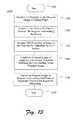
- FIG. 13is a flow chart 1300 illustrating a method for measuring within a computer generated original image on a display 340 in accordance with an embodiment. At block 1301 , the method starts.
- a user-selected movable line segment 810 , 1140 , 1142 on the original imageis adjusted to define points 750 , 760 , 1120 , 1130 , 1160 on the original image for measuring between.
- a lens surface 710 , 711 , 1110is created for one or more of the regions surrounding the points 750 , 760 , 1120 , 1130 , 1160 .
- a GUI 701 , 702 , 1101is displayed over one or more of the regions for adjusting the lens surface 710 , 711 , 1110 .
- the original imageis transformed by applying a distortion function defining the lens surface to the original image.
- the original imageis distorted 700 , 800 , 1100 in regions surrounding the points, whereby the points 750 , 760 , 1120 , 1130 , 1160 are accurately positioned for measuring.
- mapping servicesmay be accessed via a web browser. Additionally, some mapping services also have the capability of displaying satellite images, as well as maps, and of performing searches that result in addresses of locations (or regions) of interest. In some cases, these locations-of-interest may be shown on a map.
- AJAXTMwhich stands for Asynchronous JavaScript And XML
- the servicemay run JavaScriptTM on the client side, and as send requests to servers. These requests may be configured as hypertext transfer protocol (“HTTP”) requests, and in response the servers may send images (e.g., joint photographic experts group (“JPG”), graphic interchange format (“GIF”)), extensible markup language (“XML”) documents, and so on.
- JPGjoint photographic experts group
- GIFgraphic interchange format
- XMLextensible markup language
- JavaScriptmay be used to handle drawing and user interaction with the map.
- an online map serviceuses two types of data, namely, map and photo data.
- the map datais accessed using a 3-tuple index, namely, an x tile coordinate, a y tile coordinate, and a zoom level. Each zoom level is a factor of 2 larger or smaller compared with the next zoom level.
- the photo datais accessed using a single string combination of the letters ‘q’, ‘r’, ‘s’, and ‘t’. An example string would be ‘qtssstrqs.’ Each individual letter specifies a tile from a quadrant in a square, and each successive letter specifies a finer sub-quadrant in a sub-quadrant.
- Detail-in-context lensing capabilitiesmay be adapted for application to online mapping services for the purpose of improving the usability of these services, adding new functionality, providing for the insertion of new content such as advertising, and so on.
- a server-side implementationmay be desirable since with such an implementation little or no software has to be installed on the client computer beyond an Internet browser, although it should be readilby apparent that a client-side implementation is also contemplated.
- Described beloware two methods for applying detail-in-context lensing on the server side, namely, a static method and a dynamic method. Each method provides the client with lensed tiles for lensed map presentations.
- a map server(or servers) stores pre-rendered map and photo tiles for an original image.
- static lensed tilesare also stored on the server (or servers).
- the serverserves the right lensed tiles to the right user.
- the lensis not rendered on the server side, which may be advantageous.
- One drawback to this methodis that it is expensive, in terms of memory, to store each possible lensed tile on the server. However, this drawback can be alleviated by restricting lens locations and sizes.
- the focal region 420 of a lens 410may be centered on and covering a single tile with the shoulder region 430 overlapping exactly one tile in each direction surrounding the focal region 420 .
- eight (8) additional tilesare stored for each current tile in the original image, one for each of the eight directions (i.e., 45 degrees apart) from the focal region.
- a tile for the focal region 420is not stored if the lens was at a factor of two (2) in magnification as the appropriate tile would simply be from the next magnification level up which would likely already be stored on the server. This would save memory at the server.
- a quasi-static or locally-static methodin which lensed tiles are rendered and stored for a current map coverage area or that coverage area plus a surrounding buffer zone.
- lensed tilesmay be maintained in storage at the server mainly for (or only for) frequently requested coverage areas of maps such as major cities.
- an application residing on a serverthat dynamically produces lensed versions of tiles. These lensed tiles or images are then served to clients (i.e., to client applications).
- One advantage of this dynamic methodis that little or no additional storage is required at the server, plus any arbitrary lensing can be accommodated (i.e., there need be no restriction on lens position or shape).
- One drawbackis that computation time at the server is used to perform the lensing, but the storage consumed by the static method described above would be reduced. Accordingly, this dynamic method may be suitable to lensing for a typical map server implementation.
- Detail-in-context lensesmay also be applied to a non-tiled original image provided by a map server.
- map presentationsin which the whole map is presented as a single raster image rather than as a number of tile images, an alternate approach is to pre-place detail-in-context lenses 410 on an original map image prior to serving it to the client, and then serve the entire map presentation area to the client with the lenses “burned-in” to the map.
- This approachdoes not directly allow the user to interact with a map, but nonetheless can be used to draw the user's attention to features or regions-of-interest within the map.
- Interactivitymay be added through the use of “rollover” functions in which the map display is toggled from a lensed to an unlensed state, or through the use of hyptertext markup language (“HTML”) image maps to allow for redrawing of just the lensed area, or to define regions-of-interest either within lenses or identical with the lens coverage area.
- rolloverfunctions in which the map display is toggled from a lensed to an unlensed state
- HTMLhyptertext markup language
- the above static, dynamic, and non-tiled mapping methodsmay be provided through a lensing proxy service.
- map requestsare received by a proxy server with lensing capabilities.
- the proxy serverrequests appropriate tiles or images from the primary or content map server and performs lensing operations on these tiles or images based on the desired magnification and geographic location of the lens.
- proxy server lensingmay be provided as a for-pay web service which may be applied not only to maps but also to other forms of data (e.g., general images, text, etc.).
- FIG. 14is a screen capture illustrating a detail-in-context presentation 1400 in which a lens 410 is coupled to a list 1402 of search results and is applied to an online map in accordance with an embodiment.
- detail-in-context lensingmay be combined with online search results to provide users with several advantages.
- lensescan be used to freely investigate content or regions-of-interest 1404 in a view, representation, or original image.
- the viewmay be either map data or photo data, as the two can be selected independently in either the lens 410 or the context 1406 surrounding the lens 410 .
- the lens 410can be used to view a list 1402 of location search results.
- the map server 300may return search results including a list of locations 1402 .
- This list 1402may be displayed in a search results window 1408 of the presentation 1400 adjacent to a map window 1410 containing an associated map presentation 1412 .
- informationincluding the following may be presented: an address, latitude/longitude coordinates, phone number(s), name(s), a distance from a currently centered location within the map presentation 1412 , and links to content reviews or other sources of information.
- the presentation 1400shows the list 1402 of locations (i.e., the search results) and basic related data (e.g., the address of each pizza parlour found by the search) in a bar or window 1408 displayed to the right of an associated map presentation 1412 which includes a detail-in-context lens 410 .
- the usermay select a search result or item (e.g., 1414 ) in the list 1402 which will cause the lens 410 to automatically center itself over the geographic location 1416 of the selected item 1414 in the map presentation 1412 .
- a search result or iteme.g., 1414
- the selected item 1414is “Park's Garden Pizza” located at “430 Pender Street West, Vancouver, B.C.” This location may be marked with a circled dot icon 1418 within the focal region 420 of the lens 410 in the map presentation 1412 .
- the locations (e.g., 1420 ) of other non-selected items (e.g., 1422 ) in the list 1402may be marked with dot icons (e.g., 1424 ) in the map presentation 1412 .
- these icons 1418 , 1424may have any shape or design.
- lens 410is advantageous for de-cluttering purposes when related search result locations (e.g., 1416 , 1420 ) are close together, which may frequently occur, as the lens 410 magnifies the region surrounding the selected location 1416 solely.
- search result locationse.g., 1416 , 1420
- other related informationsuch as telephone numbers and reviews, may be incorporated into the presentation 1400 .
- the pathwhen a path defining driving directions to a selected location (e.g., 1416 ) from a given starting point is available, the path (not shown) may be overlaid on the map 1412 and the location of the lens 410 within the map 1412 may be constrained (or limited) to points lying on the path. In this case, the user may drag the lens 410 along the path to reveal details.
- critical decision pointse.g., street intersections
- the centroid (or focal region 420 ) of the lens 410 or another fixed point on the lens 410is constrained to one or more fixed points (e.g., intersections) or to a path defined by a polyline.
- the above described constraintsmay be selectively relaxed.
- a usermay wish to explore an area in the vicinity of a specific item or region-of-interest 1404 , such as the neighborhood or street details near a house or business shown on a digital map.
- a lens 410 located at location xmay be allowed to travel on demand (i.e., to be positioned) up to a distance 8 away from x.
- the lens 410may be constrained such that it is moveable only within a polygon containing x.
- the lens 410may be constrained to the path or up to a distance 8 from the path.
- the lens 410may be allowed to expand in extent (i.e., the area covered by the lens 410 ) to cover an area in the vicinity of a point x on a map, or to expand so as to cover a larger area in the vicinity of a constraining path on the map, if this is desired by the user or the map presenter.
- the location x of a lens 410 on a map presentationmay be set or determined based on the current location of a user.
- the current location of the usermay be obtained from a global positioning system (“GPS”) receiver (not shown) coupled to the data processing system 300 .
- GPSglobal positioning system
- movement of the lens 410may be limited or constrained to a distance c from the current location of the user. Limiting the possible lens locations to within c of x can prevent user errors such as accidentally causing the map display area to exclude the current location x.
- multiple lensesmay be positioned at or near the start and end points of a trip or path shown on a map.
- an animationis provided in which a lens 410 or lenses traverse a defined route or path for a trip as shown on a map as a function of time.
- detail-in-context lensesprovide a highlighting of areas or regions-of-interest (e.g., 1404 ) in that each region-of-interest 1404 is magnified by a lens 410 and hence is made more prominent for the user. The user's attention can be drawn to the region-of-interest 1404 in this way.
- lensescan be used to highlight locations or search results found from search queries.
- the search resultsincludes multiple items such as the list 1402 of pizza parlors 1414 , 1422 found by the search for “pizza” as illustrated in FIG.
- a lens 410may be presented over an area or region of the map corresponding to a search hit or item (e.g., 1414 ) that is selected by the user with a pointing device 310 or, alternatively, that is selected on the basis of achieving a high ranking from the search engine.
- lenses 410may be presented over advertising content in digital maps, for example, to make that content more prominent. The advertiser may pay increased fees to have such lenses presented over their advertising content.
- FIG. 15is a screen capture illustrating an online map 1500 having cluttered data (e.g., boundaries, etc.) and labels (e.g., “Montreal”, etc.).
- FIG. 16is a screen capture illustrating a detail-in-context presentation 1600 of the online map 1500 of FIG. 15 in which de-cluttering is provided in the lens 410 .
- Detail-in-context lenses 410provide a de-cluttering capability that can
- the usermay be provided with the capability of interactively moving lenses 410 in a map presentation 1600 .
- the positioning of a lens 410 by a user on a particularallow for local insertion of new content in the lens 410 when it is applied to representation such as an online map 1500 .
- representationsuch as an online map 1500 .
- the data and labelsare dense and cluttered in the region 1404 around the city of Montreal.
- the presence of a lens 410 over this region-of-interest 1404 as shown in the detail-in-context presentation 1600 of FIG. 16has increased locally the amount of blank space 1602 that is interstitial with the data and labels.
- this increase in local blank space 1602allows for the insertion of new content into the presentation 1600 such as new information relevant to the region-of-interest 1404 or new advertising content.
- the usermay be provided with the capability of interactively moving lenses 410 in a map presentation 1600 .
- the positioning of a lens 410 by a user on a particular region or location 1404indicates that the user is interested in that location (i.e., it is a region-of-interest).
- recording the locations of a lens 410 positioned by a user in an online map presentation 1600for example with text files (i.e., “cookies”) on the client computer or alternately on the server computer, is provided to allow interest in a particular region 1404 over which the lens 410 is positioned to be subsequently studied.
- Such a studymay examine the effectiveness of advertising content associated with the region 1404 , for example.
- a detail-in-context lens 410allows for additional detail or content (e.g., within blank spaces 1602 ) to be shown in the focal region 420 of the lens 410 , such as street name labels (e.g., “Pender St.”), city name labels (e.g., “Montreal”), and other geographic labels as shown in FIGS. 14 and 16 .
- street name labelse.g., “Pender St.”
- city name labelse.g., “Montreal”
- labelse.g., street names, city names, etc. appearing in a region-of-interest (e.g., 1404 ) in an online map (e.g., 1500 ) are relocated when a lens 410 is applied to the map 1500 to generate a detail-in-context presentation (e.g., 1600 ) so that the labels appear entirely within the focal region 420 of the lens 410 hence providing optimal text visibility to the user. Resizing of text fonts for the labels may also be performed. In this way, labels may be optimally placed and sized to improve legibility.
- detail-in-context lenses 410provide techniques for specifying a region-of-interest (e.g., 1404 ). This can be useful for filtering search results in cases when there may be many more results than can be easily handled. For example, if a user searches for “pizza” parlors with their map view (e.g., 1412 ) specifying all of New York City, the number of results will likely be large and difficult to sort through. According to one embodiment, using a lens 410 a user can dynamically specify a region-of-interest 1404 within the map view 1412 to limit the search.
- the items 1414 , 1422(e.g., pizza parlor locations) included in the list 1402 of search results can be filtered (e.g., in real-time) to include solely those items 1414 , 1422 that pertain to locations 1416 , 1420 that are located within the focal region 420 or lens bounds 412 (i.e., 420 , 430 ) of the lens 410 .
- FIG. 17is a flowchart illustrating operations 1700 of modules 331 within the memory 330 of a proxy server 300 for providing a presentation (e.g., 1600 ) of a region-of-interest (e.g., 1404 ) within an original image (e.g., 1500 ) to a client, the original image 1500 being stored in a content server coupled to the proxy server and the client over a network.
- a presentatione.g., 1600
- a region-of-intereste.g., 1404
- the original image 1500 from the content serveris received at the proxy server 300 .
- a lens 410is applied to the original image 1500 to produce the presentation 1600 at the proxy server 300 , the lens 410 having a focal region 420 with a magnification for the region-of-interest 1404 at least partially surrounded by a shoulder region 430 where the magnification diminishes.
- the presentation 1600is sent to the client.
- the original imagemay include one or more tile images.
- the lens 410may be applied to tile images corresponding to the region-of-interest 1404 to produce lensed tile images and the presentation 1600 may be produced by combining the lensed tile images with tile images corresponding to the original image beyond the region-of-interest (e.g., 1406 ).
- the original image 1500may be a map image.
- the methodmay further include receiving one or more signals from the client to adjust the lens 410 .
- the clientmay be adapted to display the presentation 1600 on a display screen (e.g., 340 ).
- the step of applyingmay further include displacing the original image 1500 onto the lens 410 to produce a displacement and perspectively projecting the displacement onto a plane 201 in a direction 231 aligned with a viewpoint 240 for the region-of-interest 1404 .
- the clientmay be adapted to receive the one or more signals through a graphical user interface (“GUI”) 400 displayed over the lens 410 in the presentation 1600 .
- GUI 400may be configured to adjust the lens 410 , e.g., through the use of icons (e.g., 440 , 481 , 482 , 491 , 1604 , 1606 ).
- the networkmay be the Internet
- the content servermay be a web browser server
- the clientmay be a web browser.
- sequences of instructions which when executed cause the method described herein to be performed by the exemplary data processing system of FIG. 3can be contained in a data carrier product according to one embodiment.
- This data carrier productcan be loaded into and run by the exemplary data processing system of FIG. 3 .
- sequences of instructions which when executed cause the method described herein to be performed by the exemplary data processing system of FIG. 3can be contained in a computer software product according to one embodiment.
- This computer software productcan be loaded into and run by the exemplary data processing system of FIG. 3 .
- sequences of instructions which when executed cause the method described herein to be performed by the exemplary data processing system of FIG. 3can be contained in an integrated circuit product including a coprocessor or memory according to one embodiment.
- This integrated circuit productcan be installed in the exemplary data processing system of FIG. 3 .
Landscapes
- Engineering & Computer Science (AREA)
- General Engineering & Computer Science (AREA)
- Theoretical Computer Science (AREA)
- Human Computer Interaction (AREA)
- Physics & Mathematics (AREA)
- General Physics & Mathematics (AREA)
- User Interface Of Digital Computer (AREA)
- Processing Or Creating Images (AREA)
Abstract
Description
Claims (20)
Priority Applications (1)
| Application Number | Priority Date | Filing Date | Title |
|---|---|---|---|
| US13/358,147US9804728B2 (en) | 2002-07-16 | 2012-01-25 | Detail-in-context lenses for digital image cropping, measurement and online maps |
Applications Claiming Priority (10)
| Application Number | Priority Date | Filing Date | Title |
|---|---|---|---|
| CA2393708 | 2002-07-16 | ||
| CA 2393708CA2393708A1 (en) | 2002-07-16 | 2002-07-16 | Applications of multiple lenses in detail-in-context data presentations |
| CA 2394119CA2394119A1 (en) | 2002-07-18 | 2002-07-18 | Cropping and measuring with a single lens |
| CA2394119 | 2002-07-18 | ||
| US10/614,754US7084886B2 (en) | 2002-07-16 | 2003-07-08 | Using detail-in-context lenses for accurate digital image cropping and measurement |
| US69341105P | 2005-06-24 | 2005-06-24 | |
| US11/443,124US7489321B2 (en) | 2002-07-16 | 2006-05-31 | Using detail-in-context lenses for accurate digital image cropping and measurement |
| US11/473,152US20070064018A1 (en) | 2005-06-24 | 2006-06-23 | Detail-in-context lenses for online maps |
| US12/368,267US8120624B2 (en) | 2002-07-16 | 2009-02-09 | Detail-in-context lenses for digital image cropping, measurement and online maps |
| US13/358,147US9804728B2 (en) | 2002-07-16 | 2012-01-25 | Detail-in-context lenses for digital image cropping, measurement and online maps |
Related Parent Applications (1)
| Application Number | Title | Priority Date | Filing Date |
|---|---|---|---|
| US12/368,267DivisionUS8120624B2 (en) | 2002-07-16 | 2009-02-09 | Detail-in-context lenses for digital image cropping, measurement and online maps |
Publications (2)
| Publication Number | Publication Date |
|---|---|
| US20120200606A1 US20120200606A1 (en) | 2012-08-09 |
| US9804728B2true US9804728B2 (en) | 2017-10-31 |
Family
ID=41607877
Family Applications (2)
| Application Number | Title | Priority Date | Filing Date |
|---|---|---|---|
| US12/368,267Expired - Fee RelatedUS8120624B2 (en) | 2002-07-16 | 2009-02-09 | Detail-in-context lenses for digital image cropping, measurement and online maps |
| US13/358,147Expired - LifetimeUS9804728B2 (en) | 2002-07-16 | 2012-01-25 | Detail-in-context lenses for digital image cropping, measurement and online maps |
Family Applications Before (1)
| Application Number | Title | Priority Date | Filing Date |
|---|---|---|---|
| US12/368,267Expired - Fee RelatedUS8120624B2 (en) | 2002-07-16 | 2009-02-09 | Detail-in-context lenses for digital image cropping, measurement and online maps |
Country Status (1)
| Country | Link |
|---|---|
| US (2) | US8120624B2 (en) |
Cited By (1)
| Publication number | Priority date | Publication date | Assignee | Title |
|---|---|---|---|---|
| US10585485B1 (en)* | 2014-11-10 | 2020-03-10 | Amazon Technologies, Inc. | Controlling content zoom level based on user head movement |
Families Citing this family (47)
| Publication number | Priority date | Publication date | Assignee | Title |
|---|---|---|---|---|
| CA2328795A1 (en) | 2000-12-19 | 2002-06-19 | Advanced Numerical Methods Ltd. | Applications and performance enhancements for detail-in-context viewing technology |
| US8416266B2 (en) | 2001-05-03 | 2013-04-09 | Noregin Assetts N.V., L.L.C. | Interacting with detail-in-context presentations |
| CA2345803A1 (en)* | 2001-05-03 | 2002-11-03 | Idelix Software Inc. | User interface elements for pliable display technology implementations |
| US7084886B2 (en)* | 2002-07-16 | 2006-08-01 | Idelix Software Inc. | Using detail-in-context lenses for accurate digital image cropping and measurement |
| WO2002101534A1 (en)* | 2001-06-12 | 2002-12-19 | Idelix Software Inc. | Graphical user interface with zoom for detail-in-context presentations |
| US9760235B2 (en)* | 2001-06-12 | 2017-09-12 | Callahan Cellular L.L.C. | Lens-defined adjustment of displays |
| CA2361341A1 (en) | 2001-11-07 | 2003-05-07 | Idelix Software Inc. | Use of detail-in-context presentation on stereoscopically paired images |
| CA2393887A1 (en) | 2002-07-17 | 2004-01-17 | Idelix Software Inc. | Enhancements to user interface for detail-in-context data presentation |
| CA2406131A1 (en)* | 2002-09-30 | 2004-03-30 | Idelix Software Inc. | A graphical user interface using detail-in-context folding |
| CA2407383A1 (en)* | 2002-10-10 | 2004-04-10 | Idelix Software Inc. | Editing multiple layers of a presentation using detail-in-context lenses |
| US20110069086A1 (en)* | 2002-10-10 | 2011-03-24 | Shoemaker Garth B D | Detail-in-Context Presentations in Client/Server Systems |
| CA2449888A1 (en) | 2003-11-17 | 2005-05-17 | Idelix Software Inc. | Navigating large images using detail-in-context fisheye rendering techniques |
| US7486302B2 (en)* | 2004-04-14 | 2009-02-03 | Noregin Assets N.V., L.L.C. | Fisheye lens graphical user interfaces |
| US8106927B2 (en) | 2004-05-28 | 2012-01-31 | Noregin Assets N.V., L.L.C. | Graphical user interfaces and occlusion prevention for fisheye lenses with line segment foci |
| US9317945B2 (en)* | 2004-06-23 | 2016-04-19 | Callahan Cellular L.L.C. | Detail-in-context lenses for navigation |
| US7714859B2 (en) | 2004-09-03 | 2010-05-11 | Shoemaker Garth B D | Occlusion reduction and magnification for multidimensional data presentations |
| US7995078B2 (en)* | 2004-09-29 | 2011-08-09 | Noregin Assets, N.V., L.L.C. | Compound lenses for multi-source data presentation |
| US8031206B2 (en)* | 2005-10-12 | 2011-10-04 | Noregin Assets N.V., L.L.C. | Method and system for generating pyramid fisheye lens detail-in-context presentations |
| US7983473B2 (en) | 2006-04-11 | 2011-07-19 | Noregin Assets, N.V., L.L.C. | Transparency adjustment of a presentation |
| WO2008110989A2 (en)* | 2007-03-15 | 2008-09-18 | Koninklijke Philips Electronics N.V. | Method and apparatus for editing an image |
| USD609714S1 (en)* | 2007-03-22 | 2010-02-09 | Fujifilm Corporation | Electronic camera |
| US9026938B2 (en)* | 2007-07-26 | 2015-05-05 | Noregin Assets N.V., L.L.C. | Dynamic detail-in-context user interface for application access and content access on electronic displays |
| WO2009137967A1 (en)* | 2008-05-16 | 2009-11-19 | Shanghai Hewlett-Packard Co., Ltd | Provisioning a geographical image for retrieval |
| US9141640B2 (en)* | 2008-07-09 | 2015-09-22 | MLSListings, Inc. | Methods and systems of advanced real estate searching |
| US20100153168A1 (en)* | 2008-12-15 | 2010-06-17 | Jeffrey York | System and method for carrying out an inspection or maintenance operation with compliance tracking using a handheld device |
| US8261206B2 (en)* | 2009-02-27 | 2012-09-04 | International Business Machines Corporation | Digital map having user-defined zoom areas |
| US8319801B2 (en)* | 2009-05-08 | 2012-11-27 | International Business Machines Corporation | Magnifying content on a graphical display |
| US20110231793A1 (en)* | 2010-03-17 | 2011-09-22 | Promethean Ltd | User interface selection modes |
| USD679709S1 (en)* | 2011-04-06 | 2013-04-09 | Inmusic Brands, Inc. | Book scanning device camera assembly and page compressor |
| EP2594080A4 (en)* | 2010-07-12 | 2014-11-12 | Cme Advantage Inc | Systems and methods for networked in-context, high-resolution image viewing |
| US20120011568A1 (en)* | 2010-07-12 | 2012-01-12 | Cme Advantage, Inc. | Systems and methods for collaborative, networked, in-context, high resolution image viewing |
| JP5982884B2 (en)* | 2012-03-08 | 2016-08-31 | ソニー株式会社 | Display control apparatus, display control method, and computer-readable recording medium |
| US9904457B2 (en) | 2012-04-25 | 2018-02-27 | Nokia Technologies Oy | Causing display of a three dimensional graphical user interface with dynamic selectability of items |
| US9080885B2 (en)* | 2012-06-05 | 2015-07-14 | Apple Inc. | Determining to display designations of points of interest within a map view |
| US9043722B1 (en) | 2012-06-19 | 2015-05-26 | Surfwax, Inc. | User interfaces for displaying relationships between cells in a grid |
| US10019127B2 (en) | 2012-07-31 | 2018-07-10 | Hewlett-Packard Development Company, L.P. | Remote display area including input lenses each depicting a region of a graphical user interface |
| CN104020935A (en) | 2013-02-28 | 2014-09-03 | 国际商业机器公司 | Method and device used for controlling display object on display screen |
| US9838506B1 (en) | 2013-03-15 | 2017-12-05 | Sony Interactive Entertainment America Llc | Virtual reality universe representation changes viewing based upon client side parameters |
| US20140280644A1 (en) | 2013-03-15 | 2014-09-18 | John Cronin | Real time unified communications interaction of a predefined location in a virtual reality location |
| US20140267581A1 (en) | 2013-03-15 | 2014-09-18 | John Cronin | Real time virtual reality leveraging web cams and ip cams and web cam and ip cam networks |
| US20140280502A1 (en) | 2013-03-15 | 2014-09-18 | John Cronin | Crowd and cloud enabled virtual reality distributed location network |
| US9588343B2 (en)* | 2014-01-25 | 2017-03-07 | Sony Interactive Entertainment America Llc | Menu navigation in a head-mounted display |
| EP3170131A2 (en)* | 2014-03-04 | 2017-05-24 | Google, Inc. | Map personalization based on social clues |
| USD821413S1 (en) | 2017-02-23 | 2018-06-26 | Google Llc | Display screen with graphical user interface |
| JP7399164B2 (en) | 2019-03-16 | 2023-12-15 | エヌビディア コーポレーション | Object detection using skewed polygons suitable for parking space detection |
| US11977723B2 (en)* | 2019-12-17 | 2024-05-07 | Palantir Technologies Inc. | Image tiling and distributive modification |
| US11461945B2 (en)* | 2020-12-28 | 2022-10-04 | Mapbox, Inc. | Multi-phase label placement process for rendering map tiles |
Citations (278)
| Publication number | Priority date | Publication date | Assignee | Title |
|---|---|---|---|---|
| US3201546A (en) | 1961-07-24 | 1965-08-17 | Hart Mfg Canada Ltd | Power controlling device for electrical heating elements |
| US3704938A (en) | 1970-10-01 | 1972-12-05 | Hyman Fanselow | Punch card viewer |
| US3739739A (en) | 1972-08-24 | 1973-06-19 | R Brase | Instrument for isolating rows of printed matter for reading |
| US3762799A (en) | 1971-08-27 | 1973-10-02 | J Shapiro | Magnifying indicator for a burette |
| US4581647A (en) | 1983-09-19 | 1986-04-08 | Vye Richard A | Computerized automatic focusing control system for multiple television cameras |
| US4630110A (en) | 1984-02-15 | 1986-12-16 | Supervision Control Systems, Inc. | Surveillance system |
| US4688181A (en) | 1982-12-22 | 1987-08-18 | International Business Machines Corporation | Image transformations on an interactive raster scan or matrix display |
| US4757616A (en) | 1987-10-26 | 1988-07-19 | Educational Insights | Ruler with magnifying cursor |
| US4790028A (en) | 1986-09-12 | 1988-12-06 | Westinghouse Electric Corp. | Method and apparatus for generating variably scaled displays |
| US4800379A (en)* | 1986-05-12 | 1989-01-24 | Crosfield Electronics Limited | Image display with movable magnification |
| US4885702A (en) | 1985-07-27 | 1989-12-05 | Sony Corporation | Method of forming curved surfaces and the apparatus |
| US4888713A (en) | 1986-09-05 | 1989-12-19 | Cdi Technologies, Inc. | Surface detail mapping system |
| US4970028A (en) | 1987-09-24 | 1990-11-13 | Lever Brothers Company | Composition for softening fabrics |
| US4985849A (en) | 1987-06-12 | 1991-01-15 | Canon Kabushiki Kaisha | Image processing system for forming a slantwise-mapped or rotated modified image of an original image |
| US4992866A (en) | 1989-06-29 | 1991-02-12 | Morgan Jack B | Camera selection and positioning system and method |
| US5031918A (en) | 1990-04-24 | 1991-07-16 | Fred Silber Compamy | Magnifying marker for a game board |
| US5048077A (en) | 1988-07-25 | 1991-09-10 | Reflection Technology, Inc. | Telephone handset with full-page visual display |
| US5175808A (en) | 1989-09-12 | 1992-12-29 | Pixar | Method and apparatus for non-affine image warping |
| US5185667A (en) | 1991-05-13 | 1993-02-09 | Telerobotics International, Inc. | Omniview motionless camera orientation system |
| US5185599A (en) | 1987-10-26 | 1993-02-09 | Tektronix, Inc. | Local display bus architecture and communications method for Raster display |
| US5200818A (en) | 1991-03-22 | 1993-04-06 | Inbal Neta | Video imaging system with interactive windowing capability |
| US5206721A (en) | 1990-03-08 | 1993-04-27 | Fujitsu Limited | Television conference system |
| US5227771A (en) | 1991-07-10 | 1993-07-13 | International Business Machines Corporation | Method and system for incrementally changing window size on a display |
| US5250934A (en) | 1990-12-31 | 1993-10-05 | Xerox Corporation | Method and apparatus for thinning printed images |
| US5258837A (en) | 1991-01-07 | 1993-11-02 | Zandar Research Limited | Multiple security video display |
| US5269687A (en) | 1990-08-01 | 1993-12-14 | Atari Games Corporation | System and method for recursive driver training |
| US5275019A (en) | 1991-06-26 | 1994-01-04 | C.T.P. S.P.A. | Functional ring |
| US5309279A (en) | 1992-08-21 | 1994-05-03 | Halstead Madeline C | Script view a curved convex magnifying device |
| US5321807A (en) | 1991-11-27 | 1994-06-14 | Mumford Christopher J | Accelerated graphics display method |
| US5329310A (en) | 1992-06-30 | 1994-07-12 | The Walt Disney Company | Method and apparatus for controlling distortion of a projected image |
| US5341466A (en) | 1991-05-09 | 1994-08-23 | New York University | Fractal computer user centerface with zooming capability |
| US5369527A (en) | 1992-12-03 | 1994-11-29 | Mccracken; Robert | Melanoma detection device |
| EP0635779A1 (en) | 1993-07-21 | 1995-01-25 | Xerox Corporation | User interface having movable sheet with click-through tools |
| EP0650144A1 (en) | 1993-10-26 | 1995-04-26 | Xerox Corporation | Image lens |
| US5416900A (en) | 1991-04-25 | 1995-05-16 | Lotus Development Corporation | Presentation manager |
| US5432895A (en) | 1992-10-01 | 1995-07-11 | University Corporation For Atmospheric Research | Virtual reality imaging system |
| US5451998A (en) | 1994-04-04 | 1995-09-19 | Hamrick; Daniel C. | Home shopping video catalog |
| US5459488A (en) | 1990-07-21 | 1995-10-17 | Robert Bosch Gmbh | Graphical user interface with fisheye adaptation principle |
| US5473740A (en) | 1993-12-29 | 1995-12-05 | International Business Machines Corporation | Method and apparatus for interactively indicating image boundaries in digital image cropping |
| US5521634A (en) | 1994-06-17 | 1996-05-28 | Harris Corporation | Automatic detection and prioritized image transmission system and method |
| US5523783A (en) | 1992-10-19 | 1996-06-04 | Fuji Photo Optical Co., Ltd. | Pan head control system for TV camera |
| US5528289A (en) | 1993-10-20 | 1996-06-18 | Videoconferencing Systems, Inc. | Method for automatically adjusting a videoconferencing system camera to center an object |
| US5539534A (en) | 1992-06-03 | 1996-07-23 | Hitachi, Ltd. | Method of scaling an image capable of line width preservation |
| US5583977A (en) | 1993-10-21 | 1996-12-10 | Taligent, Inc. | Object-oriented curve manipulation system |
| US5588098A (en) | 1991-11-22 | 1996-12-24 | Apple Computer, Inc. | Method and apparatus for direct manipulation of 3-D objects on computer displays |
| US5594859A (en) | 1992-06-03 | 1997-01-14 | Digital Equipment Corporation | Graphical user interface for video teleconferencing |
| US5596690A (en) | 1993-07-21 | 1997-01-21 | Xerox Corporation | Method and apparatus for operating on an object-based model data structure to produce a second image in the spatial context of a first image |
| US5598297A (en) | 1993-08-26 | 1997-01-28 | Sharp Kabushiki Kaisha | Image display unit |
| US5610653A (en) | 1992-02-07 | 1997-03-11 | Abecassis; Max | Method and system for automatically tracking a zoomed video image |
| US5613032A (en) | 1994-09-02 | 1997-03-18 | Bell Communications Research, Inc. | System and method for recording, playing back and searching multimedia events wherein video, audio and text can be searched and retrieved |
| US5638523A (en) | 1993-01-26 | 1997-06-10 | Sun Microsystems, Inc. | Method and apparatus for browsing information in a computer database |
| US5644758A (en) | 1994-12-13 | 1997-07-01 | Microsoft Corporation | Bitmap block transfer image conversion |
| US5651107A (en) | 1992-12-15 | 1997-07-22 | Sun Microsystems, Inc. | Method and apparatus for presenting information in a display system using transparent windows |
| US5652851A (en) | 1993-07-21 | 1997-07-29 | Xerox Corporation | User interface technique for producing a second image in the spatial context of a first image using a model-based operation |
| US5657246A (en) | 1995-03-07 | 1997-08-12 | Vtel Corporation | Method and apparatus for a video conference user interface |
| US5680524A (en) | 1994-04-21 | 1997-10-21 | Sandia Corporation | Synthetic environment employing a craft for providing user perspective reference |
| US5682489A (en) | 1991-06-04 | 1997-10-28 | Digital Equipment Corporation, Inc. | Method and device for monitoring, manipulating, and viewing system information |
| US5689628A (en) | 1994-04-14 | 1997-11-18 | Xerox Corporation | Coupling a display object to a viewpoint in a navigable workspace |
| US5689287A (en) | 1993-10-27 | 1997-11-18 | Xerox Corporation | Context-preserving display system using a perspective sheet |
| EP0816986A2 (en) | 1996-07-03 | 1998-01-07 | Hitachi, Ltd. | Method, apparatus and system for recognizing motions |
| EP0816983A2 (en) | 1996-06-25 | 1998-01-07 | Sun Microsystems, Inc. | Method and apparatus for eyetrack-driven text enlargement |
| US5721853A (en) | 1995-04-28 | 1998-02-24 | Ast Research, Inc. | Spot graphic display element with open locking and periodic animation |
| US5726670A (en)* | 1992-07-20 | 1998-03-10 | Olympus Optical Co., Ltd. | Display apparatus to be mounted on the head or face of an individual |
| US5729673A (en) | 1995-04-07 | 1998-03-17 | Avid Technology, Inc. | Direct manipulation of two-dimensional moving picture streams in three-dimensional space |
| US5742272A (en) | 1996-04-29 | 1998-04-21 | Ati Technologies Inc. | Accelerated full screen video playback |
| US5745166A (en) | 1994-07-26 | 1998-04-28 | Maxpro Systems Pty Ltd | Video security system field of the invention |
| US5751289A (en) | 1992-10-01 | 1998-05-12 | University Corporation For Atmospheric Research | Virtual reality imaging system with image replay |
| US5754348A (en) | 1996-05-14 | 1998-05-19 | Planetweb, Inc. | Method for context-preserving magnification of digital image regions |
| US5764139A (en) | 1995-11-06 | 1998-06-09 | Toyota Jidosha Kabushiki Kaisha | Information display apparatus for vehicles |
| US5786814A (en) | 1995-11-03 | 1998-07-28 | Xerox Corporation | Computer controlled display system activities using correlated graphical and timeline interfaces for controlling replay of temporal data representing collaborative activities |
| US5798752A (en) | 1993-07-21 | 1998-08-25 | Xerox Corporation | User interface having simultaneously movable tools and cursor |
| US5808670A (en) | 1995-02-17 | 1998-09-15 | Nec System Integration & Construction, Ltd. | Method and system for camera control with monitoring area view |
| US5812111A (en) | 1994-08-30 | 1998-09-22 | Nec Corporation | Bifocal picture display system |
| US5818455A (en) | 1993-07-21 | 1998-10-06 | Xerox Corporation | Method and apparatus for operating on the model data structure of an image to produce human perceptible output using a viewing operation region having explicit multiple regions |
| US5848231A (en) | 1996-02-12 | 1998-12-08 | Teitelbaum; Neil | System configuration contingent upon secure input |
| US5852440A (en) | 1994-04-13 | 1998-12-22 | International Business Machines Corporation | Method and system for facilitating the selection of icons |
| US5909219A (en) | 1996-06-28 | 1999-06-01 | Cirrus Logic, Inc. | Embedding a transparency enable bit as part of a resizing bit block transfer operation |
| US5926209A (en) | 1995-07-14 | 1999-07-20 | Sensormatic Electronics Corporation | Video camera apparatus with compression system responsive to video camera adjustment |
| US5950216A (en) | 1996-11-12 | 1999-09-07 | International Business Machines Corporation | Method and system for marking and subsequently retrieving a collection of objects within a multipage compound document utilizing selectable page numbered dialog boxes |
| US5949430A (en) | 1997-05-20 | 1999-09-07 | Microsoft Corporation | Peripheral lenses for simulating peripheral vision on a display device |
| US5959605A (en) | 1995-11-22 | 1999-09-28 | Picker International, Inc. | Video magnifier |
| US5969706A (en) | 1995-10-16 | 1999-10-19 | Sharp Kabushiki Kaisha | Information retrieval apparatus and method |
| US5973694A (en) | 1995-06-02 | 1999-10-26 | Chatham Telecommunications, Inc., | Method of communication using sized icons, text, and audio |
| US5991877A (en) | 1997-04-03 | 1999-11-23 | Lockheed Martin Corporation | Object-oriented trusted application framework |
| US5999879A (en) | 1996-04-26 | 1999-12-07 | Pioneer Electronic Corporation | Navigation apparatus with shape change display function |
| US6005611A (en) | 1994-05-27 | 1999-12-21 | Be Here Corporation | Wide-angle image dewarping method and apparatus |
| US6037939A (en) | 1995-09-27 | 2000-03-14 | Sharp Kabushiki Kaisha | Method for enabling interactive manipulation of data retained in computer system, and a computer system for implementing the method |
| US6052110A (en) | 1998-05-11 | 2000-04-18 | Sony Corporation | Dynamic control of zoom operation in computer graphics |
| US6057844A (en) | 1997-04-28 | 2000-05-02 | Adobe Systems Incorporated | Drag operation gesture controller |
| US6064401A (en) | 1998-05-28 | 2000-05-16 | Ncr Corporation | User interface controls for adjusting the display of multi-dimensional graphical plots |
| US6067372A (en) | 1996-02-22 | 2000-05-23 | University Of Pittsburgh | Method and system to enhance robust identification of abnormal regions in radiographs |
| US6072501A (en) | 1997-06-27 | 2000-06-06 | Xerox Corporation | Method and apparatus for composing layered synthetic graphics filters |
| US6073036A (en) | 1997-04-28 | 2000-06-06 | Nokia Mobile Phones Limited | Mobile station with touch input having automatic symbol magnification function |
| US6075531A (en) | 1997-12-15 | 2000-06-13 | International Business Machines Corporation | Computer system and method of manipulating multiple graphical user interface components on a computer display with a proximity pointer |
| US6081277A (en) | 1995-09-28 | 2000-06-27 | Sony Corporation | Apparatus and method for controlling image display |
| US6084598A (en) | 1998-04-23 | 2000-07-04 | Chekerylla; James | Apparatus for modifying graphic images |
| US6091771A (en) | 1997-08-01 | 2000-07-18 | Wells Fargo Alarm Services, Inc. | Workstation for video security system |
| US6108005A (en) | 1996-08-30 | 2000-08-22 | Space Corporation | Method for producing a synthesized stereoscopic image |
| US6128024A (en) | 1997-12-18 | 2000-10-03 | Hewlett-Packard Company | Polar controller for defining and generating spiral-like shapes |
| US6133914A (en) | 1998-01-07 | 2000-10-17 | Rogers; David W. | Interactive graphical user interface |
| US6147709A (en) | 1997-04-07 | 2000-11-14 | Interactive Pictures Corporation | Method and apparatus for inserting a high resolution image into a low resolution interactive image to produce a realistic immersive experience |
| US6154840A (en) | 1998-05-01 | 2000-11-28 | Northern Telecom Limited | System and method for transferring encrypted sections of documents across a computer network |
| US6160553A (en) | 1998-09-14 | 2000-12-12 | Microsoft Corporation | Methods, apparatus and data structures for providing a user interface, which exploits spatial memory in three-dimensions, to objects and in which object occlusion is avoided |
| US6184859B1 (en) | 1995-04-21 | 2001-02-06 | Sony Corporation | Picture display apparatus |
| US6198484B1 (en) | 1996-06-27 | 2001-03-06 | Kabushiki Kaisha Toshiba | Stereoscopic display system |
| US6201546B1 (en) | 1998-05-29 | 2001-03-13 | Point Cloud, Inc. | Systems and methods for generating three dimensional, textured models |
| US6201548B1 (en) | 1998-02-24 | 2001-03-13 | Hewlett-Packard Company | Graphical user interface for image editing |
| US6204845B1 (en) | 1994-12-16 | 2001-03-20 | International Business Machines Corporation | Ergonomic viewable object processor |
| US6204850B1 (en) | 1997-05-30 | 2001-03-20 | Daniel R. Green | Scaleable camera model for the navigation and display of information structures using nested, bounded 3D coordinate spaces |
| US6215491B1 (en) | 1992-12-14 | 2001-04-10 | Monkeymedia, Inc. | Computer user interface with non-salience deemphasis |
| US6241609B1 (en) | 1998-01-09 | 2001-06-05 | U.S. Philips Corporation | Virtual environment viewpoint control |
| US6249281B1 (en) | 2000-02-28 | 2001-06-19 | Presenter.Com | On-demand presentation graphical user interface |
| US6256737B1 (en) | 1999-03-09 | 2001-07-03 | Bionetrix Systems Corporation | System, method and computer program product for allowing access to enterprise resources using biometric devices |
| US6256115B1 (en) | 1997-02-21 | 2001-07-03 | Worldquest Network, Inc. | Facsimile network |
| US6256043B1 (en) | 1997-09-26 | 2001-07-03 | Lucent Technologies Inc. | Three dimensional virtual reality enhancement techniques |
| US6266082B1 (en) | 1995-12-19 | 2001-07-24 | Canon Kabushiki Kaisha | Communication apparatus image processing apparatus communication method and image processing method |
| US6271854B1 (en) | 1997-12-15 | 2001-08-07 | Intel Corporation | Method and apparatus for facilitating navigation in three-dimensional graphic scenes |
| US6278443B1 (en) | 1998-04-30 | 2001-08-21 | International Business Machines Corporation | Touch screen with random finger placement and rolling on screen to control the movement of information on-screen |
| US6278450B1 (en) | 1998-06-17 | 2001-08-21 | Microsoft Corporation | System and method for customizing controls on a toolbar |
| US6288702B1 (en) | 1996-09-30 | 2001-09-11 | Kabushiki Kaisha Toshiba | Information device having enlargement display function and enlargement display control method |
| US6304271B1 (en) | 1999-02-05 | 2001-10-16 | Sony Corporation | Apparatus and method for cropping an image in a zooming graphical user interface |
| US6307612B1 (en) | 2000-06-08 | 2001-10-23 | Three-Five Systems, Inc. | Liquid crystal display element having a precisely controlled cell gap and method of making same |
| US20010040585A1 (en) | 1998-08-18 | 2001-11-15 | Stephen A Hartford | Resizing multi-dimensionally rendered graphical images |
| US20010040636A1 (en) | 1994-11-17 | 2001-11-15 | Eiji Kato | Camera control and display device using graphical user interface |
| US6320599B1 (en) | 1998-05-11 | 2001-11-20 | Sony Corporation | Zooming scale indicator in computer graphics |
| US20010048447A1 (en) | 2000-06-05 | 2001-12-06 | Fuji Photo Film Co., Ltd. | Image croppin and synthesizing method, and imaging apparatus |
| US20010055030A1 (en) | 2000-06-22 | 2001-12-27 | Lc Electronics Inc. | Apparatus and method for correcting keyston distortion |
| US6337709B1 (en) | 1995-02-13 | 2002-01-08 | Hitachi, Ltd. | Image display device |
| US6346962B1 (en) | 1998-02-27 | 2002-02-12 | International Business Machines Corporation | Control of video conferencing system with pointing device |
| US6346938B1 (en) | 1999-04-27 | 2002-02-12 | Harris Corporation | Computer-resident mechanism for manipulating, navigating through and mensurating displayed image of three-dimensional geometric model |
| US6359615B1 (en) | 1999-05-11 | 2002-03-19 | Ericsson Inc. | Movable magnification icons for electronic device display screens |
| US20020033837A1 (en) | 2000-01-10 | 2002-03-21 | Munro James A. | Multiple-image viewer |
| US20020038257A1 (en) | 1994-04-28 | 2002-03-28 | Kuriacose Joseph | Apparatus for transmitting and receiving executable applications as for a multimedia system |
| US20020044154A1 (en)* | 2000-10-18 | 2002-04-18 | Baar David J. P. | Elastic presentation space |
| US6381583B1 (en) | 1997-04-15 | 2002-04-30 | John A. Kenney | Interactive electronic shopping system and method |
| US6384849B1 (en) | 1997-07-14 | 2002-05-07 | Microsoft Corporation | Method for displaying controls in a system using a graphical user interface |
| US6392661B1 (en) | 1998-06-17 | 2002-05-21 | Trident Systems, Inc. | Method and apparatus for improving situational awareness using multiple map displays employing peripheral range bands |
| US20020062245A1 (en) | 2000-03-09 | 2002-05-23 | David Niu | System and method for generating real-time promotions on an electronic commerce world wide website to increase the likelihood of purchase |
| US6396962B1 (en) | 1999-01-29 | 2002-05-28 | Sony Corporation | System and method for providing zooming video |
| US6396648B1 (en) | 1999-03-30 | 2002-05-28 | Nec Corporation | Image reader which can shorten focal length in optical system having optical lens while keeping predetermined image reading width |
| US6400848B1 (en) | 1999-03-30 | 2002-06-04 | Eastman Kodak Company | Method for modifying the perspective of a digital image |
| US6407747B1 (en) | 1999-05-07 | 2002-06-18 | Picsurf, Inc. | Computer screen image magnification system and method |
| US20020075280A1 (en) | 2000-12-19 | 2002-06-20 | Tigges Mark H. A. | Method and system for inversion of detail-in-context presentations |
| US6411274B2 (en) | 1997-06-02 | 2002-06-25 | Sony Corporation | Digital map display zooming method, digital map display zooming device, and storage medium for storing digital map display zooming program |
| US20020087894A1 (en) | 2001-01-03 | 2002-07-04 | Foley James M. | Method and apparatus for enabling a user to select an authentication method |
| US6417867B1 (en) | 1999-05-27 | 2002-07-09 | Sharp Laboratories Of America, Inc. | Image downscaling using peripheral vision area localization |
| US6416186B1 (en) | 1999-08-23 | 2002-07-09 | Nec Corporation | Projection display unit |
| US20020089520A1 (en) | 2000-12-19 | 2002-07-11 | Baar David J.P. | Method and system for enhanced detail-in-context viewing |
| US20020093567A1 (en) | 2001-01-12 | 2002-07-18 | International Business Machines Corporation | Method and system for generating a digital photographic proof |
| US20020101396A1 (en) | 2000-04-14 | 2002-08-01 | Huston James R. | Balanced binary color drive method for graphical displays and system implementing same |
| US6438576B1 (en) | 1999-03-29 | 2002-08-20 | International Business Machines Corporation | Method and apparatus of a collaborative proxy system for distributed deployment of object rendering |
| US20020122038A1 (en) | 2000-09-06 | 2002-09-05 | David Cowperthwaite | Occlusion reducing transformations for three-dimensional detail-in-context viewing |
| US20020143826A1 (en) | 2001-03-29 | 2002-10-03 | International Business Machines Corporation | Method, apparatus, and program for magnifying the text of a link while still retaining browser function in the magnified display |
| CA2350342A1 (en) | 2001-05-03 | 2002-11-03 | Idelix Software Inc. | Extension of detail-in-context data presentation with interface to full zoom function |
| US20020171644A1 (en) | 2001-03-31 | 2002-11-21 | Reshetov Alexander V. | Spatial patches for graphics rendering |
| US6487497B2 (en) | 1998-03-25 | 2002-11-26 | Navigation Technologies Corporation | Method and system for route calculation in a navigation application |
| US20020180801A1 (en) | 2001-05-03 | 2002-12-05 | Michael Doyle | Graphical user interface for detail-in-context presentations |
| US6491585B1 (en) | 1996-09-24 | 2002-12-10 | Nintendo Co., Ltd. | Three-dimensional image processing apparatus with enhanced automatic and user point of view control |
| US6504535B1 (en) | 1998-06-30 | 2003-01-07 | Lucent Technologies Inc. | Display techniques for three-dimensional virtual reality |
| US20030007006A1 (en) | 2001-06-12 | 2003-01-09 | David Baar | Graphical user interface with zoom for detail-in-context presentations |
| US20030006995A1 (en) | 2001-06-15 | 2003-01-09 | Smith Randall B. | Orthogonal magnifier within a computer system display |
| US6515678B1 (en) | 1999-11-18 | 2003-02-04 | Gateway, Inc. | Video magnifier for a display of data |
| US6515663B1 (en) | 1999-03-19 | 2003-02-04 | Asustek Computer Inc. | Apparatus for and method of processing three-dimensional images |
| US6523024B1 (en) | 1994-03-18 | 2003-02-18 | Hitachi, Ltd. | Methods for retrieving database with image information |
| US6522341B1 (en) | 1999-06-02 | 2003-02-18 | Matsushita Electric Industrial Co., Ltd. | Multi-layer image mixing apparatus |
| US20030048447A1 (en) | 2001-09-07 | 2003-03-13 | Raimo Harju | Accurate instrumetation for optical measurement of samples |
| US20030052900A1 (en) | 2000-12-21 | 2003-03-20 | Card Stuart Kent | Magnification methods, systems, and computer program products for virtual three-dimensional books |
| US20030052896A1 (en) | 2000-03-29 | 2003-03-20 | Higgins Darin Wayne | System and method for synchronizing map images |
| US20030061211A1 (en) | 2000-06-30 | 2003-03-27 | Shultz Troy L. | GIS based search engine |
| US6542191B1 (en) | 1996-04-23 | 2003-04-01 | Canon Kabushiki Kaisha | Image display apparatus, camera control apparatus and method |
| US6549215B2 (en)* | 1999-05-20 | 2003-04-15 | Compaq Computer Corporation | System and method for displaying images using anamorphic video |
| US6552737B1 (en) | 1999-02-18 | 2003-04-22 | Fujitsu Limited | Control of window size in response to user operation |
| US20030076363A1 (en) | 2001-10-18 | 2003-04-24 | Murphy Killian D. | Digital image magnification for internet appliance |
| US6559813B1 (en) | 1998-07-01 | 2003-05-06 | Deluca Michael | Selective real image obstruction in a virtual reality display apparatus and method |
| US20030100326A1 (en) | 2001-11-27 | 2003-05-29 | Grube Gary W. | Group location and route sharing system for communication units in a trunked communication system |
| US20030103063A1 (en) | 2001-12-03 | 2003-06-05 | Tempest Microsystems | Panoramic imaging and display system with canonical magnifier |
| US20030105795A1 (en) | 2001-11-30 | 2003-06-05 | Anderson Jeff M. | Image editing via batch commands |
| US6577319B1 (en) | 1998-09-18 | 2003-06-10 | Sharp Kabushiki Kaisha | Method for controlling data display |
| US6577311B1 (en) | 1999-12-16 | 2003-06-10 | Picture Iq Corporation | Techniques for automatically providing a high-resolution rendering of a low resolution digital image in a distributed network |
| US20030112503A1 (en) | 2001-11-07 | 2003-06-19 | Maria Lantin | Method and system for displaying stereoscopic detail-in-context presentations |
| US6584237B1 (en) | 1999-08-23 | 2003-06-24 | Pentax Corporation | Method and apparatus for expanding image data |
| US20030118223A1 (en) | 2001-08-10 | 2003-06-26 | Rahn J. Richard | Method and apparatus for three-dimensional imaging in the fourier domain |
| US6590568B1 (en) | 2000-11-20 | 2003-07-08 | Nokia Corporation | Touch screen drag and drop input technique |
| US20030137525A1 (en) | 2002-01-24 | 2003-07-24 | Smith Randall B. | Method and apparatus for facilitating motion-coupled magnification |
| US20030151625A1 (en) | 2002-02-05 | 2003-08-14 | Shoemaker Garth B.D. | Fast and accurate rendering of pliable display technology distortions using pre-calculated texel coverages |
| US20030151626A1 (en) | 2002-02-05 | 2003-08-14 | Robert Komar | Fast rendering of pyramid lens distorted raster images |
| US6608631B1 (en) | 2000-05-02 | 2003-08-19 | Pixar Amination Studios | Method, apparatus, and computer program product for geometric warps and deformations |
| US6612930B2 (en) | 1998-11-19 | 2003-09-02 | Nintendo Co., Ltd. | Video game apparatus and method with enhanced virtual camera control |
| US20030174146A1 (en) | 2002-02-04 | 2003-09-18 | Michael Kenoyer | Apparatus and method for providing electronic image manipulation in video conferencing applications |
| US20030179219A1 (en) | 2002-03-08 | 2003-09-25 | International Business Machines Corporation | Image display device, image display method, and image display program |
| US20030179237A1 (en) | 2002-03-22 | 2003-09-25 | Nelson Lester D. | System and method for arranging, manipulating and displaying objects in a graphical user interface |
| US20030179198A1 (en) | 1999-07-08 | 2003-09-25 | Shinji Uchiyama | Stereoscopic image processing apparatus and method, stereoscopic vision parameter setting apparatus and method, and computer program storage medium information processing method and apparatus |
| US6631205B1 (en) | 1999-01-13 | 2003-10-07 | Canon Kabushiki Kaisha | Stereoscopic imaging in a portable document format |
| US6633305B1 (en) | 2000-06-05 | 2003-10-14 | Corel Corporation | System and method for magnifying and editing images |
| US20030196114A1 (en) | 2002-04-10 | 2003-10-16 | International Business Machines | Persistent access control of protected content |
| US20030210281A1 (en) | 2002-05-07 | 2003-11-13 | Troy Ellis | Magnifying a thumbnail image of a document |
| CA2386560A1 (en) | 2002-05-15 | 2003-11-15 | Idelix Software Inc. | Controlling optical hardware and dynamic data viewing systems with detail-in-context viewing tools |
| US20030231177A1 (en) | 2002-05-17 | 2003-12-18 | Catherine Montagnese | Method and system for inversion of detail-in-context presentations with folding |
| CA2393708A1 (en) | 2002-07-16 | 2004-01-16 | Idelix Software Inc. | Applications of multiple lenses in detail-in-context data presentations |
| CA2394119A1 (en) | 2002-07-18 | 2004-01-18 | Idelix Software Inc. | Cropping and measuring with a single lens |
| US6690387B2 (en) | 2001-12-28 | 2004-02-10 | Koninklijke Philips Electronics N.V. | Touch-screen image scrolling system and method |
| US20040026521A1 (en) | 2002-05-22 | 2004-02-12 | Alex Colas | Linear proportional valve |
| US6704034B1 (en) | 2000-09-28 | 2004-03-09 | International Business Machines Corporation | Method and apparatus for providing accessibility through a context sensitive magnifying glass |
| US20040056869A1 (en) | 2002-07-16 | 2004-03-25 | Zeenat Jetha | Using detail-in-context lenses for accurate digital image cropping and measurement |
| US20040056898A1 (en) | 2002-07-17 | 2004-03-25 | Zeenat Jetha | Graphical user interface having an attached toolbar for drag and drop editing in detail-in-context lens presentations |
| US6721655B1 (en) | 2001-03-14 | 2004-04-13 | Mitsubishi Denki Kabushiki Kaisha | Vehicle travel guide device and vehicle travel guide method |
| US6720971B1 (en) | 1998-05-29 | 2004-04-13 | Canon Kabushiki Kaisha | Image processing method and apparatus, and storage medium |
| US6731315B1 (en) | 1999-11-30 | 2004-05-04 | International Business Machines Corporation | Method for selecting display parameters of a magnifiable cursor |
| US6731285B2 (en) | 2001-01-11 | 2004-05-04 | International Business Machines Corporation | System and method for providing high performance image magnification in a web browser |
| US6744430B1 (en) | 1999-07-21 | 2004-06-01 | Sega Enterprises, Ltd. | Image processing method and its apparatus |
| US6747610B1 (en) | 1997-07-22 | 2004-06-08 | Sanyo Electric Co., Ltd. | Stereoscopic image display apparatus capable of selectively displaying desired stereoscopic image |
| US6747611B1 (en) | 2000-07-27 | 2004-06-08 | International Business Machines Corporation | Compact optical system and packaging for head mounted display |
| US20040111332A1 (en) | 2002-09-30 | 2004-06-10 | David Baar | Detail-in-context lenses for interacting with objects in digital image presentations |
| US20040125138A1 (en) | 2002-10-10 | 2004-07-01 | Zeenat Jetha | Detail-in-context lenses for multi-layer images |
| US6760020B1 (en) | 1998-06-30 | 2004-07-06 | Canon Kabushiki Kaisha | Image processing apparatus for displaying three-dimensional image |
| US20040150664A1 (en) | 2003-02-03 | 2004-08-05 | Microsoft Corporation | System and method for accessing remote screen content |
| US20040194014A1 (en) | 2000-04-14 | 2004-09-30 | Picsel Technologies Limited | User interface systems and methods for viewing and manipulating digital documents |
| US20040240709A1 (en) | 2003-04-22 | 2004-12-02 | Garth Shoemaker | Method and system for controlling detail-in-context lenses through eye and position tracking |
| US20040257380A1 (en) | 2003-06-20 | 2004-12-23 | Herbert Leslie B. | Imaging method and system |
| US6842175B1 (en) | 1999-04-22 | 2005-01-11 | Fraunhofer Usa, Inc. | Tools for interacting with virtual environments |
| US6874126B1 (en) | 2001-11-30 | 2005-03-29 | View Space Technologies | Method and apparatus for controlling content display by the cursor motion |
| US6882755B2 (en) | 2001-10-19 | 2005-04-19 | Hewlett-Packard Development Company, L.P. | Image transmission for low bandwidth with region of interest |
| US20050086612A1 (en)* | 2003-07-25 | 2005-04-21 | David Gettman | Graphical user interface for an information display system |
| US6906643B2 (en) | 2003-04-30 | 2005-06-14 | Hewlett-Packard Development Company, L.P. | Systems and methods of viewing, modifying, and interacting with “path-enhanced” multimedia |
| US20050134610A1 (en) | 2003-11-17 | 2005-06-23 | Michael Doyle | Navigating digital images using detail-in-context lenses |
| US6911975B2 (en) | 2000-09-11 | 2005-06-28 | Canon Kabushiki Kaisha | Stereo image display apparatus and method, and storage medium |
| US6919921B1 (en) | 1997-06-10 | 2005-07-19 | Canon Kabushiki Kaisha | Camera control using scroll bar for tilt control and having display of tilting direction and controllable range information |
| US6938218B1 (en) | 2000-04-28 | 2005-08-30 | James Nolen | Method and apparatus for three dimensional internet and computer file interface |
| US6956590B1 (en) | 2001-02-28 | 2005-10-18 | Navteq North America, Llc | Method of providing visual continuity when panning and zooming with a map display |
| US6975335B2 (en) | 1999-12-28 | 2005-12-13 | International Business Machines Corporation | Method of displaying magnified and reduced areas and apparatus thereof |
| US20050278378A1 (en) | 2004-05-19 | 2005-12-15 | Metacarta, Inc. | Systems and methods of geographical text indexing |
| US20050285861A1 (en) | 2004-06-23 | 2005-12-29 | Idelix Software, Inc. | Detail-in-context lenses for navigation |
| US6985865B1 (en) | 2001-09-26 | 2006-01-10 | Sprint Spectrum L.P. | Method and system for enhanced response to voice commands in a voice command platform |
| US20060026521A1 (en) | 2004-07-30 | 2006-02-02 | Apple Computer, Inc. | Gestures for touch sensitive input devices |
| US20060022955A1 (en) | 2004-07-30 | 2006-02-02 | Apple Computer, Inc. | Visual expander |
| US20060036629A1 (en) | 2003-01-28 | 2006-02-16 | Microsoft Corporation | System and process for identifying objects and/or points nearby a given object or point |
| US20060059432A1 (en) | 2004-09-15 | 2006-03-16 | Matthew Bells | User interface having viewing area with non-transparent and semi-transparent regions |
| US20060082901A1 (en) | 2004-10-14 | 2006-04-20 | Idelix Software Inc. | Interacting with detail-in-context presentations |
| US7038680B2 (en) | 2002-01-09 | 2006-05-02 | Xerox Corporation | System for graphical display and interactive exploratory analysis of data and data relationships |
| US20060098028A1 (en) | 2004-09-29 | 2006-05-11 | Idelix Software Inc. | Compound lenses for multi-source data presentation |
| US7055095B1 (en) | 2000-04-14 | 2006-05-30 | Picsel Research Limited | Systems and methods for digital document processing |
| US20060139375A1 (en) | 2004-03-23 | 2006-06-29 | Rasmussen Jens E | Secondary map in digital mapping system |
| US7071971B2 (en) | 1997-08-25 | 2006-07-04 | Elbex Video Ltd. | Apparatus for identifying the scene location viewed via remotely operated television camera |
| US7133054B2 (en) | 2004-03-17 | 2006-11-07 | Seadragon Software, Inc. | Methods and apparatus for navigating an image |
| US7134092B2 (en) | 2000-11-13 | 2006-11-07 | James Nolen | Graphical user interface method and apparatus |
| US7158878B2 (en) | 2004-03-23 | 2007-01-02 | Google Inc. | Digital mapping system |
| US7173636B2 (en) | 2004-03-18 | 2007-02-06 | Idelix Software Inc. | Method and system for generating detail-in-context lens presentations for elevation data |
| US20070033543A1 (en) | 2005-08-04 | 2007-02-08 | Microsoft Corporation | Virtual magnifying glass with intuitive use enhancements |
| US7194697B2 (en) | 2002-09-24 | 2007-03-20 | Microsoft Corporation | Magnification engine |
| US20070064018A1 (en) | 2005-06-24 | 2007-03-22 | Idelix Software Inc. | Detail-in-context lenses for online maps |
| US7197718B1 (en) | 1999-10-18 | 2007-03-27 | Sharp Laboratories Of America, Inc. | Interactive virtual area browser for selecting and rescaling graphical representations of displayed data |
| US20070097109A1 (en) | 2005-10-18 | 2007-05-03 | Idelix Software Inc. | Method and system for generating detail-in-context presentations in client/server systems |
| US7233942B2 (en) | 2000-10-10 | 2007-06-19 | Truelocal Inc. | Method and apparatus for providing geographically authenticated electronic documents |
| US7246109B1 (en) | 1999-10-07 | 2007-07-17 | Koninklijke Philips Electronics N.V. | Method and apparatus for browsing using position information |
| US20070218900A1 (en)* | 2006-03-17 | 2007-09-20 | Raj Vasant Abhyanker | Map based neighborhood search and community contribution |
| US7312806B2 (en) | 2004-01-28 | 2007-12-25 | Idelix Software Inc. | Dynamic width adjustment for detail-in-context lenses |
| US7321824B1 (en) | 2002-12-30 | 2008-01-22 | Aol Llc | Presenting a travel route using more than one presentation style |
| US20080086368A1 (en)* | 2006-10-05 | 2008-04-10 | Google Inc. | Location Based, Content Targeted Online Advertising |
| US7423660B2 (en) | 2003-09-26 | 2008-09-09 | Canon Kabushiki Kaisha | Image display apparatus, method and program |
| US7443396B2 (en) | 2000-11-29 | 2008-10-28 | National Instruments Corporation | Instrument having a virtual magnifying glass for displaying magnified portions of a signal waveform |
| US20080268876A1 (en)* | 2007-04-24 | 2008-10-30 | Natasha Gelfand | Method, Device, Mobile Terminal, and Computer Program Product for a Point of Interest Based Scheme for Improving Mobile Visual Searching Functionalities |
| US7450114B2 (en) | 2000-04-14 | 2008-11-11 | Picsel (Research) Limited | User interface systems and methods for manipulating and viewing digital documents |
| US20080319990A1 (en)* | 2007-06-18 | 2008-12-25 | Geographic Services, Inc. | Geographic feature name search system |
| US7486302B2 (en) | 2004-04-14 | 2009-02-03 | Noregin Assets N.V., L.L.C. | Fisheye lens graphical user interfaces |
| US7493572B2 (en) | 2000-12-21 | 2009-02-17 | Xerox Corporation | Navigation methods, systems, and computer program products for virtual three-dimensional books |
| US20090172587A1 (en) | 2007-07-26 | 2009-07-02 | Idelix Software Inc. | Dynamic detail-in-context user interface for application access and content access on electronic displays |
| US7580036B2 (en) | 2005-04-13 | 2009-08-25 | Catherine Montagnese | Detail-in-context terrain displacement algorithm with optimizations |
| US20090284542A1 (en) | 2001-06-12 | 2009-11-19 | Noregin Assets N.V., L.L.C. | Lens-defined adjustment of displays |
| US20090284530A1 (en)* | 2006-12-19 | 2009-11-19 | Celeritasworks, Llc | Campaign awareness management systems and methods |
| US7698653B2 (en) | 1999-11-04 | 2010-04-13 | Roman Kendyl A | Graphical user interface including zoom control box representing image and magnification of displayed image |
| US7714859B2 (en) | 2004-09-03 | 2010-05-11 | Shoemaker Garth B D | Occlusion reduction and magnification for multidimensional data presentations |
| US20100118025A1 (en)* | 2005-04-21 | 2010-05-13 | Microsoft Corporation | Mode information displayed in a mapping application |
| US20100149114A1 (en) | 2008-12-16 | 2010-06-17 | Motorola, Inc. | Simulating a multi-touch screen on a single-touch screen |
| US7761713B2 (en) | 2002-11-15 | 2010-07-20 | Baar David J P | Method and system for controlling access in detail-in-context presentations |
| US20100262907A1 (en) | 2001-05-03 | 2010-10-14 | Shoemaker Garth B D | Interacting with Detail-in-Context Presentations |
| US20110061003A1 (en)* | 2008-04-11 | 2011-03-10 | Cirius Technologies, Inc. | Advertisement display method, advertisement display system, and advertisement display program |
| US20110161861A1 (en)* | 2001-04-30 | 2011-06-30 | Activemap Llc | Interactive Electronically Presented Map |
| US20120239509A1 (en)* | 2008-02-01 | 2012-09-20 | Google Inc. | Online map advertising |
Family Cites Families (1)
| Publication number | Priority date | Publication date | Assignee | Title |
|---|---|---|---|---|
| US6956988B2 (en)* | 1998-08-21 | 2005-10-18 | Avanex Corporation | Optical interleaver |
- 2009
- 2009-02-09USUS12/368,267patent/US8120624B2/ennot_activeExpired - Fee Related
- 2012
- 2012-01-25USUS13/358,147patent/US9804728B2/ennot_activeExpired - Lifetime
Patent Citations (329)
| Publication number | Priority date | Publication date | Assignee | Title |
|---|---|---|---|---|
| US3201546A (en) | 1961-07-24 | 1965-08-17 | Hart Mfg Canada Ltd | Power controlling device for electrical heating elements |
| US3704938A (en) | 1970-10-01 | 1972-12-05 | Hyman Fanselow | Punch card viewer |
| US3762799A (en) | 1971-08-27 | 1973-10-02 | J Shapiro | Magnifying indicator for a burette |
| US3739739A (en) | 1972-08-24 | 1973-06-19 | R Brase | Instrument for isolating rows of printed matter for reading |
| US4688181A (en) | 1982-12-22 | 1987-08-18 | International Business Machines Corporation | Image transformations on an interactive raster scan or matrix display |
| US4581647A (en) | 1983-09-19 | 1986-04-08 | Vye Richard A | Computerized automatic focusing control system for multiple television cameras |
| US4630110A (en) | 1984-02-15 | 1986-12-16 | Supervision Control Systems, Inc. | Surveillance system |
| US4885702A (en) | 1985-07-27 | 1989-12-05 | Sony Corporation | Method of forming curved surfaces and the apparatus |
| US4800379A (en)* | 1986-05-12 | 1989-01-24 | Crosfield Electronics Limited | Image display with movable magnification |
| US4888713A (en) | 1986-09-05 | 1989-12-19 | Cdi Technologies, Inc. | Surface detail mapping system |
| US4888713B1 (en) | 1986-09-05 | 1993-10-12 | Cdi Technologies, Inc. | Surface detail mapping system |
| US4790028A (en) | 1986-09-12 | 1988-12-06 | Westinghouse Electric Corp. | Method and apparatus for generating variably scaled displays |
| US4985849A (en) | 1987-06-12 | 1991-01-15 | Canon Kabushiki Kaisha | Image processing system for forming a slantwise-mapped or rotated modified image of an original image |
| US4970028A (en) | 1987-09-24 | 1990-11-13 | Lever Brothers Company | Composition for softening fabrics |
| US4757616A (en) | 1987-10-26 | 1988-07-19 | Educational Insights | Ruler with magnifying cursor |
| US5185599A (en) | 1987-10-26 | 1993-02-09 | Tektronix, Inc. | Local display bus architecture and communications method for Raster display |
| US5048077A (en) | 1988-07-25 | 1991-09-10 | Reflection Technology, Inc. | Telephone handset with full-page visual display |
| US4992866A (en) | 1989-06-29 | 1991-02-12 | Morgan Jack B | Camera selection and positioning system and method |
| US5175808A (en) | 1989-09-12 | 1992-12-29 | Pixar | Method and apparatus for non-affine image warping |
| US5206721A (en) | 1990-03-08 | 1993-04-27 | Fujitsu Limited | Television conference system |
| US5031918A (en) | 1990-04-24 | 1991-07-16 | Fred Silber Compamy | Magnifying marker for a game board |
| US5459488A (en) | 1990-07-21 | 1995-10-17 | Robert Bosch Gmbh | Graphical user interface with fisheye adaptation principle |
| US5269687A (en) | 1990-08-01 | 1993-12-14 | Atari Games Corporation | System and method for recursive driver training |
| US5250934A (en) | 1990-12-31 | 1993-10-05 | Xerox Corporation | Method and apparatus for thinning printed images |
| US5258837A (en) | 1991-01-07 | 1993-11-02 | Zandar Research Limited | Multiple security video display |
| US5200818A (en) | 1991-03-22 | 1993-04-06 | Inbal Neta | Video imaging system with interactive windowing capability |
| US5416900A (en) | 1991-04-25 | 1995-05-16 | Lotus Development Corporation | Presentation manager |
| US5341466A (en) | 1991-05-09 | 1994-08-23 | New York University | Fractal computer user centerface with zooming capability |
| US5185667A (en) | 1991-05-13 | 1993-02-09 | Telerobotics International, Inc. | Omniview motionless camera orientation system |
| US5682489A (en) | 1991-06-04 | 1997-10-28 | Digital Equipment Corporation, Inc. | Method and device for monitoring, manipulating, and viewing system information |
| US5275019A (en) | 1991-06-26 | 1994-01-04 | C.T.P. S.P.A. | Functional ring |
| US5227771A (en) | 1991-07-10 | 1993-07-13 | International Business Machines Corporation | Method and system for incrementally changing window size on a display |
| US5588098A (en) | 1991-11-22 | 1996-12-24 | Apple Computer, Inc. | Method and apparatus for direct manipulation of 3-D objects on computer displays |
| US5321807A (en) | 1991-11-27 | 1994-06-14 | Mumford Christopher J | Accelerated graphics display method |
| US5610653A (en) | 1992-02-07 | 1997-03-11 | Abecassis; Max | Method and system for automatically tracking a zoomed video image |
| US5594859A (en) | 1992-06-03 | 1997-01-14 | Digital Equipment Corporation | Graphical user interface for video teleconferencing |
| US5539534A (en) | 1992-06-03 | 1996-07-23 | Hitachi, Ltd. | Method of scaling an image capable of line width preservation |
| US5329310A (en) | 1992-06-30 | 1994-07-12 | The Walt Disney Company | Method and apparatus for controlling distortion of a projected image |
| US5726670A (en)* | 1992-07-20 | 1998-03-10 | Olympus Optical Co., Ltd. | Display apparatus to be mounted on the head or face of an individual |
| US5309279A (en) | 1992-08-21 | 1994-05-03 | Halstead Madeline C | Script view a curved convex magnifying device |
| US5432895A (en) | 1992-10-01 | 1995-07-11 | University Corporation For Atmospheric Research | Virtual reality imaging system |
| US5751289A (en) | 1992-10-01 | 1998-05-12 | University Corporation For Atmospheric Research | Virtual reality imaging system with image replay |
| US5523783A (en) | 1992-10-19 | 1996-06-04 | Fuji Photo Optical Co., Ltd. | Pan head control system for TV camera |
| US5369527A (en) | 1992-12-03 | 1994-11-29 | Mccracken; Robert | Melanoma detection device |
| US6219052B1 (en) | 1992-12-14 | 2001-04-17 | Monkeymedia, Inc. | Computer user interface with non-salience deemphasis |
| US6215491B1 (en) | 1992-12-14 | 2001-04-10 | Monkeymedia, Inc. | Computer user interface with non-salience deemphasis |
| US5651107A (en) | 1992-12-15 | 1997-07-22 | Sun Microsystems, Inc. | Method and apparatus for presenting information in a display system using transparent windows |
| US5638523A (en) | 1993-01-26 | 1997-06-10 | Sun Microsystems, Inc. | Method and apparatus for browsing information in a computer database |
| US5596690A (en) | 1993-07-21 | 1997-01-21 | Xerox Corporation | Method and apparatus for operating on an object-based model data structure to produce a second image in the spatial context of a first image |
| US5818455A (en) | 1993-07-21 | 1998-10-06 | Xerox Corporation | Method and apparatus for operating on the model data structure of an image to produce human perceptible output using a viewing operation region having explicit multiple regions |
| EP0635779A1 (en) | 1993-07-21 | 1995-01-25 | Xerox Corporation | User interface having movable sheet with click-through tools |
| US5798752A (en) | 1993-07-21 | 1998-08-25 | Xerox Corporation | User interface having simultaneously movable tools and cursor |
| US5652851A (en) | 1993-07-21 | 1997-07-29 | Xerox Corporation | User interface technique for producing a second image in the spatial context of a first image using a model-based operation |
| US5581670A (en) | 1993-07-21 | 1996-12-03 | Xerox Corporation | User interface having movable sheet with click-through tools |
| US5598297A (en) | 1993-08-26 | 1997-01-28 | Sharp Kabushiki Kaisha | Image display unit |
| US5528289A (en) | 1993-10-20 | 1996-06-18 | Videoconferencing Systems, Inc. | Method for automatically adjusting a videoconferencing system camera to center an object |
| US5583977A (en) | 1993-10-21 | 1996-12-10 | Taligent, Inc. | Object-oriented curve manipulation system |
| US5670984A (en) | 1993-10-26 | 1997-09-23 | Xerox Corporation | Image lens |
| EP0650144A1 (en) | 1993-10-26 | 1995-04-26 | Xerox Corporation | Image lens |
| US5689287A (en) | 1993-10-27 | 1997-11-18 | Xerox Corporation | Context-preserving display system using a perspective sheet |
| US5473740A (en) | 1993-12-29 | 1995-12-05 | International Business Machines Corporation | Method and apparatus for interactively indicating image boundaries in digital image cropping |
| US6523024B1 (en) | 1994-03-18 | 2003-02-18 | Hitachi, Ltd. | Methods for retrieving database with image information |
| US5451998A (en) | 1994-04-04 | 1995-09-19 | Hamrick; Daniel C. | Home shopping video catalog |
| US5852440A (en) | 1994-04-13 | 1998-12-22 | International Business Machines Corporation | Method and system for facilitating the selection of icons |
| US5689628A (en) | 1994-04-14 | 1997-11-18 | Xerox Corporation | Coupling a display object to a viewpoint in a navigable workspace |
| US5680524A (en) | 1994-04-21 | 1997-10-21 | Sandia Corporation | Synthetic environment employing a craft for providing user perspective reference |
| US20020038257A1 (en) | 1994-04-28 | 2002-03-28 | Kuriacose Joseph | Apparatus for transmitting and receiving executable applications as for a multimedia system |
| US6005611A (en) | 1994-05-27 | 1999-12-21 | Be Here Corporation | Wide-angle image dewarping method and apparatus |
| US5521634A (en) | 1994-06-17 | 1996-05-28 | Harris Corporation | Automatic detection and prioritized image transmission system and method |
| US5923364A (en) | 1994-07-26 | 1999-07-13 | Maxpro Systems Pty Ltd | Video security system |
| US5745166A (en) | 1994-07-26 | 1998-04-28 | Maxpro Systems Pty Ltd | Video security system field of the invention |
| US5812111A (en) | 1994-08-30 | 1998-09-22 | Nec Corporation | Bifocal picture display system |
| US5613032A (en) | 1994-09-02 | 1997-03-18 | Bell Communications Research, Inc. | System and method for recording, playing back and searching multimedia events wherein video, audio and text can be searched and retrieved |
| US20010040636A1 (en) | 1994-11-17 | 2001-11-15 | Eiji Kato | Camera control and display device using graphical user interface |
| US5644758A (en) | 1994-12-13 | 1997-07-01 | Microsoft Corporation | Bitmap block transfer image conversion |
| US6204845B1 (en) | 1994-12-16 | 2001-03-20 | International Business Machines Corporation | Ergonomic viewable object processor |
| US6337709B1 (en) | 1995-02-13 | 2002-01-08 | Hitachi, Ltd. | Image display device |
| US5808670A (en) | 1995-02-17 | 1998-09-15 | Nec System Integration & Construction, Ltd. | Method and system for camera control with monitoring area view |
| US5872922A (en) | 1995-03-07 | 1999-02-16 | Vtel Corporation | Method and apparatus for a video conference user interface |
| US5657246A (en) | 1995-03-07 | 1997-08-12 | Vtel Corporation | Method and apparatus for a video conference user interface |
| US5729673A (en) | 1995-04-07 | 1998-03-17 | Avid Technology, Inc. | Direct manipulation of two-dimensional moving picture streams in three-dimensional space |
| US6184859B1 (en) | 1995-04-21 | 2001-02-06 | Sony Corporation | Picture display apparatus |
| US5721853A (en) | 1995-04-28 | 1998-02-24 | Ast Research, Inc. | Spot graphic display element with open locking and periodic animation |
| US5973694A (en) | 1995-06-02 | 1999-10-26 | Chatham Telecommunications, Inc., | Method of communication using sized icons, text, and audio |
| US5926209A (en) | 1995-07-14 | 1999-07-20 | Sensormatic Electronics Corporation | Video camera apparatus with compression system responsive to video camera adjustment |
| US6037939A (en) | 1995-09-27 | 2000-03-14 | Sharp Kabushiki Kaisha | Method for enabling interactive manipulation of data retained in computer system, and a computer system for implementing the method |
| US6081277A (en) | 1995-09-28 | 2000-06-27 | Sony Corporation | Apparatus and method for controlling image display |
| US5969706A (en) | 1995-10-16 | 1999-10-19 | Sharp Kabushiki Kaisha | Information retrieval apparatus and method |
| US5786814A (en) | 1995-11-03 | 1998-07-28 | Xerox Corporation | Computer controlled display system activities using correlated graphical and timeline interfaces for controlling replay of temporal data representing collaborative activities |
| US5764139A (en) | 1995-11-06 | 1998-06-09 | Toyota Jidosha Kabushiki Kaisha | Information display apparatus for vehicles |
| US5959605A (en) | 1995-11-22 | 1999-09-28 | Picker International, Inc. | Video magnifier |
| US6266082B1 (en) | 1995-12-19 | 2001-07-24 | Canon Kabushiki Kaisha | Communication apparatus image processing apparatus communication method and image processing method |
| US5848231A (en) | 1996-02-12 | 1998-12-08 | Teitelbaum; Neil | System configuration contingent upon secure input |
| US6067372A (en) | 1996-02-22 | 2000-05-23 | University Of Pittsburgh | Method and system to enhance robust identification of abnormal regions in radiographs |
| US6542191B1 (en) | 1996-04-23 | 2003-04-01 | Canon Kabushiki Kaisha | Image display apparatus, camera control apparatus and method |
| US5999879A (en) | 1996-04-26 | 1999-12-07 | Pioneer Electronic Corporation | Navigation apparatus with shape change display function |
| US5742272A (en) | 1996-04-29 | 1998-04-21 | Ati Technologies Inc. | Accelerated full screen video playback |
| US6590583B2 (en) | 1996-05-14 | 2003-07-08 | Planetweb, Inc. | Method for context-preserving magnification of digital image regions |
| US5754348A (en) | 1996-05-14 | 1998-05-19 | Planetweb, Inc. | Method for context-preserving magnification of digital image regions |
| EP0816983A2 (en) | 1996-06-25 | 1998-01-07 | Sun Microsystems, Inc. | Method and apparatus for eyetrack-driven text enlargement |
| US5731805A (en) | 1996-06-25 | 1998-03-24 | Sun Microsystems, Inc. | Method and apparatus for eyetrack-driven text enlargement |
| US6198484B1 (en) | 1996-06-27 | 2001-03-06 | Kabushiki Kaisha Toshiba | Stereoscopic display system |
| US5909219A (en) | 1996-06-28 | 1999-06-01 | Cirrus Logic, Inc. | Embedding a transparency enable bit as part of a resizing bit block transfer operation |
| EP0816986A2 (en) | 1996-07-03 | 1998-01-07 | Hitachi, Ltd. | Method, apparatus and system for recognizing motions |
| US6108005A (en) | 1996-08-30 | 2000-08-22 | Space Corporation | Method for producing a synthesized stereoscopic image |
| US6491585B1 (en) | 1996-09-24 | 2002-12-10 | Nintendo Co., Ltd. | Three-dimensional image processing apparatus with enhanced automatic and user point of view control |
| US6288702B1 (en) | 1996-09-30 | 2001-09-11 | Kabushiki Kaisha Toshiba | Information device having enlargement display function and enlargement display control method |
| US5950216A (en) | 1996-11-12 | 1999-09-07 | International Business Machines Corporation | Method and system for marking and subsequently retrieving a collection of objects within a multipage compound document utilizing selectable page numbered dialog boxes |
| US6256115B1 (en) | 1997-02-21 | 2001-07-03 | Worldquest Network, Inc. | Facsimile network |
| US5991877A (en) | 1997-04-03 | 1999-11-23 | Lockheed Martin Corporation | Object-oriented trusted application framework |
| US6147709A (en) | 1997-04-07 | 2000-11-14 | Interactive Pictures Corporation | Method and apparatus for inserting a high resolution image into a low resolution interactive image to produce a realistic immersive experience |
| US6381583B1 (en) | 1997-04-15 | 2002-04-30 | John A. Kenney | Interactive electronic shopping system and method |
| US6057844A (en) | 1997-04-28 | 2000-05-02 | Adobe Systems Incorporated | Drag operation gesture controller |
| US6073036A (en) | 1997-04-28 | 2000-06-06 | Nokia Mobile Phones Limited | Mobile station with touch input having automatic symbol magnification function |
| US6246411B1 (en) | 1997-04-28 | 2001-06-12 | Adobe Systems Incorporated | Drag operation gesture controller |
| US5949430A (en) | 1997-05-20 | 1999-09-07 | Microsoft Corporation | Peripheral lenses for simulating peripheral vision on a display device |
| US6204850B1 (en) | 1997-05-30 | 2001-03-20 | Daniel R. Green | Scaleable camera model for the navigation and display of information structures using nested, bounded 3D coordinate spaces |
| US20020135601A1 (en) | 1997-06-02 | 2002-09-26 | Sony Corporation | Digital map display zooming method, digital map display zooming device, and storage medium for storing digital map display zooming program |
| US6411274B2 (en) | 1997-06-02 | 2002-06-25 | Sony Corporation | Digital map display zooming method, digital map display zooming device, and storage medium for storing digital map display zooming program |
| US6919921B1 (en) | 1997-06-10 | 2005-07-19 | Canon Kabushiki Kaisha | Camera control using scroll bar for tilt control and having display of tilting direction and controllable range information |
| US6072501A (en) | 1997-06-27 | 2000-06-06 | Xerox Corporation | Method and apparatus for composing layered synthetic graphics filters |
| US6384849B1 (en) | 1997-07-14 | 2002-05-07 | Microsoft Corporation | Method for displaying controls in a system using a graphical user interface |
| US6747610B1 (en) | 1997-07-22 | 2004-06-08 | Sanyo Electric Co., Ltd. | Stereoscopic image display apparatus capable of selectively displaying desired stereoscopic image |
| US6091771A (en) | 1997-08-01 | 2000-07-18 | Wells Fargo Alarm Services, Inc. | Workstation for video security system |
| US7071971B2 (en) | 1997-08-25 | 2006-07-04 | Elbex Video Ltd. | Apparatus for identifying the scene location viewed via remotely operated television camera |
| US6256043B1 (en) | 1997-09-26 | 2001-07-03 | Lucent Technologies Inc. | Three dimensional virtual reality enhancement techniques |
| US6271854B1 (en) | 1997-12-15 | 2001-08-07 | Intel Corporation | Method and apparatus for facilitating navigation in three-dimensional graphic scenes |
| US6075531A (en) | 1997-12-15 | 2000-06-13 | International Business Machines Corporation | Computer system and method of manipulating multiple graphical user interface components on a computer display with a proximity pointer |
| US6128024A (en) | 1997-12-18 | 2000-10-03 | Hewlett-Packard Company | Polar controller for defining and generating spiral-like shapes |
| US6133914A (en) | 1998-01-07 | 2000-10-17 | Rogers; David W. | Interactive graphical user interface |
| US6241609B1 (en) | 1998-01-09 | 2001-06-05 | U.S. Philips Corporation | Virtual environment viewpoint control |
| US6201548B1 (en) | 1998-02-24 | 2001-03-13 | Hewlett-Packard Company | Graphical user interface for image editing |
| US6346962B1 (en) | 1998-02-27 | 2002-02-12 | International Business Machines Corporation | Control of video conferencing system with pointing device |
| US6487497B2 (en) | 1998-03-25 | 2002-11-26 | Navigation Technologies Corporation | Method and system for route calculation in a navigation application |
| US6084598A (en) | 1998-04-23 | 2000-07-04 | Chekerylla; James | Apparatus for modifying graphic images |
| US6278443B1 (en) | 1998-04-30 | 2001-08-21 | International Business Machines Corporation | Touch screen with random finger placement and rolling on screen to control the movement of information on-screen |
| US6154840A (en) | 1998-05-01 | 2000-11-28 | Northern Telecom Limited | System and method for transferring encrypted sections of documents across a computer network |
| US6052110A (en) | 1998-05-11 | 2000-04-18 | Sony Corporation | Dynamic control of zoom operation in computer graphics |
| US6320599B1 (en) | 1998-05-11 | 2001-11-20 | Sony Corporation | Zooming scale indicator in computer graphics |
| US6064401A (en) | 1998-05-28 | 2000-05-16 | Ncr Corporation | User interface controls for adjusting the display of multi-dimensional graphical plots |
| US6720971B1 (en) | 1998-05-29 | 2004-04-13 | Canon Kabushiki Kaisha | Image processing method and apparatus, and storage medium |
| US6201546B1 (en) | 1998-05-29 | 2001-03-13 | Point Cloud, Inc. | Systems and methods for generating three dimensional, textured models |
| US6392661B1 (en) | 1998-06-17 | 2002-05-21 | Trident Systems, Inc. | Method and apparatus for improving situational awareness using multiple map displays employing peripheral range bands |
| US6278450B1 (en) | 1998-06-17 | 2001-08-21 | Microsoft Corporation | System and method for customizing controls on a toolbar |
| US6504535B1 (en) | 1998-06-30 | 2003-01-07 | Lucent Technologies Inc. | Display techniques for three-dimensional virtual reality |
| US6760020B1 (en) | 1998-06-30 | 2004-07-06 | Canon Kabushiki Kaisha | Image processing apparatus for displaying three-dimensional image |
| US6559813B1 (en) | 1998-07-01 | 2003-05-06 | Deluca Michael | Selective real image obstruction in a virtual reality display apparatus and method |
| US20010040585A1 (en) | 1998-08-18 | 2001-11-15 | Stephen A Hartford | Resizing multi-dimensionally rendered graphical images |
| US6160553A (en) | 1998-09-14 | 2000-12-12 | Microsoft Corporation | Methods, apparatus and data structures for providing a user interface, which exploits spatial memory in three-dimensions, to objects and in which object occlusion is avoided |
| US6577319B1 (en) | 1998-09-18 | 2003-06-10 | Sharp Kabushiki Kaisha | Method for controlling data display |
| US6612930B2 (en) | 1998-11-19 | 2003-09-02 | Nintendo Co., Ltd. | Video game apparatus and method with enhanced virtual camera control |
| US6631205B1 (en) | 1999-01-13 | 2003-10-07 | Canon Kabushiki Kaisha | Stereoscopic imaging in a portable document format |
| US6396962B1 (en) | 1999-01-29 | 2002-05-28 | Sony Corporation | System and method for providing zooming video |
| US6304271B1 (en) | 1999-02-05 | 2001-10-16 | Sony Corporation | Apparatus and method for cropping an image in a zooming graphical user interface |
| US6552737B1 (en) | 1999-02-18 | 2003-04-22 | Fujitsu Limited | Control of window size in response to user operation |
| US6256737B1 (en) | 1999-03-09 | 2001-07-03 | Bionetrix Systems Corporation | System, method and computer program product for allowing access to enterprise resources using biometric devices |
| US6515663B1 (en) | 1999-03-19 | 2003-02-04 | Asustek Computer Inc. | Apparatus for and method of processing three-dimensional images |
| US6438576B1 (en) | 1999-03-29 | 2002-08-20 | International Business Machines Corporation | Method and apparatus of a collaborative proxy system for distributed deployment of object rendering |
| US6400848B1 (en) | 1999-03-30 | 2002-06-04 | Eastman Kodak Company | Method for modifying the perspective of a digital image |
| US6396648B1 (en) | 1999-03-30 | 2002-05-28 | Nec Corporation | Image reader which can shorten focal length in optical system having optical lens while keeping predetermined image reading width |
| US6842175B1 (en) | 1999-04-22 | 2005-01-11 | Fraunhofer Usa, Inc. | Tools for interacting with virtual environments |
| US6346938B1 (en) | 1999-04-27 | 2002-02-12 | Harris Corporation | Computer-resident mechanism for manipulating, navigating through and mensurating displayed image of three-dimensional geometric model |
| US6407747B1 (en) | 1999-05-07 | 2002-06-18 | Picsurf, Inc. | Computer screen image magnification system and method |
| US6359615B1 (en) | 1999-05-11 | 2002-03-19 | Ericsson Inc. | Movable magnification icons for electronic device display screens |
| US6549215B2 (en)* | 1999-05-20 | 2003-04-15 | Compaq Computer Corporation | System and method for displaying images using anamorphic video |
| US6417867B1 (en) | 1999-05-27 | 2002-07-09 | Sharp Laboratories Of America, Inc. | Image downscaling using peripheral vision area localization |
| US6522341B1 (en) | 1999-06-02 | 2003-02-18 | Matsushita Electric Industrial Co., Ltd. | Multi-layer image mixing apparatus |
| US20030179198A1 (en) | 1999-07-08 | 2003-09-25 | Shinji Uchiyama | Stereoscopic image processing apparatus and method, stereoscopic vision parameter setting apparatus and method, and computer program storage medium information processing method and apparatus |
| US6744430B1 (en) | 1999-07-21 | 2004-06-01 | Sega Enterprises, Ltd. | Image processing method and its apparatus |
| US6584237B1 (en) | 1999-08-23 | 2003-06-24 | Pentax Corporation | Method and apparatus for expanding image data |
| US6416186B1 (en) | 1999-08-23 | 2002-07-09 | Nec Corporation | Projection display unit |
| US7246109B1 (en) | 1999-10-07 | 2007-07-17 | Koninklijke Philips Electronics N.V. | Method and apparatus for browsing using position information |
| US7197718B1 (en) | 1999-10-18 | 2007-03-27 | Sharp Laboratories Of America, Inc. | Interactive virtual area browser for selecting and rescaling graphical representations of displayed data |
| US7698653B2 (en) | 1999-11-04 | 2010-04-13 | Roman Kendyl A | Graphical user interface including zoom control box representing image and magnification of displayed image |
| US6515678B1 (en) | 1999-11-18 | 2003-02-04 | Gateway, Inc. | Video magnifier for a display of data |
| US6731315B1 (en) | 1999-11-30 | 2004-05-04 | International Business Machines Corporation | Method for selecting display parameters of a magnifiable cursor |
| US6577311B1 (en) | 1999-12-16 | 2003-06-10 | Picture Iq Corporation | Techniques for automatically providing a high-resolution rendering of a low resolution digital image in a distributed network |
| US6975335B2 (en) | 1999-12-28 | 2005-12-13 | International Business Machines Corporation | Method of displaying magnified and reduced areas and apparatus thereof |
| US20020033837A1 (en) | 2000-01-10 | 2002-03-21 | Munro James A. | Multiple-image viewer |
| US6249281B1 (en) | 2000-02-28 | 2001-06-19 | Presenter.Com | On-demand presentation graphical user interface |
| US20020062245A1 (en) | 2000-03-09 | 2002-05-23 | David Niu | System and method for generating real-time promotions on an electronic commerce world wide website to increase the likelihood of purchase |
| US20030052896A1 (en) | 2000-03-29 | 2003-03-20 | Higgins Darin Wayne | System and method for synchronizing map images |
| US20040194014A1 (en) | 2000-04-14 | 2004-09-30 | Picsel Technologies Limited | User interface systems and methods for viewing and manipulating digital documents |
| US20020101396A1 (en) | 2000-04-14 | 2002-08-01 | Huston James R. | Balanced binary color drive method for graphical displays and system implementing same |
| US7055095B1 (en) | 2000-04-14 | 2006-05-30 | Picsel Research Limited | Systems and methods for digital document processing |
| US7450114B2 (en) | 2000-04-14 | 2008-11-11 | Picsel (Research) Limited | User interface systems and methods for manipulating and viewing digital documents |
| US6938218B1 (en) | 2000-04-28 | 2005-08-30 | James Nolen | Method and apparatus for three dimensional internet and computer file interface |
| US6608631B1 (en) | 2000-05-02 | 2003-08-19 | Pixar Amination Studios | Method, apparatus, and computer program product for geometric warps and deformations |
| US20010048447A1 (en) | 2000-06-05 | 2001-12-06 | Fuji Photo Film Co., Ltd. | Image croppin and synthesizing method, and imaging apparatus |
| US6633305B1 (en) | 2000-06-05 | 2003-10-14 | Corel Corporation | System and method for magnifying and editing images |
| US6307612B1 (en) | 2000-06-08 | 2001-10-23 | Three-Five Systems, Inc. | Liquid crystal display element having a precisely controlled cell gap and method of making same |
| US20010055030A1 (en) | 2000-06-22 | 2001-12-27 | Lc Electronics Inc. | Apparatus and method for correcting keyston distortion |
| US20030061211A1 (en) | 2000-06-30 | 2003-03-27 | Shultz Troy L. | GIS based search engine |
| US6747611B1 (en) | 2000-07-27 | 2004-06-08 | International Business Machines Corporation | Compact optical system and packaging for head mounted display |
| US20020122038A1 (en) | 2000-09-06 | 2002-09-05 | David Cowperthwaite | Occlusion reducing transformations for three-dimensional detail-in-context viewing |
| US7280105B2 (en) | 2000-09-06 | 2007-10-09 | Idelix Software Inc. | Occlusion reducing transformations for three-dimensional detail-in-context viewing |
| US6798412B2 (en) | 2000-09-06 | 2004-09-28 | Idelix Software Inc. | Occlusion reducing transformations for three-dimensional detail-in-context viewing |
| US20040257375A1 (en) | 2000-09-06 | 2004-12-23 | David Cowperthwaite | Occlusion reducing transformations for three-dimensional detail-in-context viewing |
| US6911975B2 (en) | 2000-09-11 | 2005-06-28 | Canon Kabushiki Kaisha | Stereo image display apparatus and method, and storage medium |
| US6704034B1 (en) | 2000-09-28 | 2004-03-09 | International Business Machines Corporation | Method and apparatus for providing accessibility through a context sensitive magnifying glass |
| US7233942B2 (en) | 2000-10-10 | 2007-06-19 | Truelocal Inc. | Method and apparatus for providing geographically authenticated electronic documents |
| US20050041046A1 (en) | 2000-10-18 | 2005-02-24 | Baar David J.P. | Elastic presentation space |
| US6768497B2 (en) | 2000-10-18 | 2004-07-27 | Idelix Software Inc. | Elastic presentation space |
| US7256801B2 (en) | 2000-10-18 | 2007-08-14 | Idelix Software Inc. | Elastic presentation space |
| JP4410465B2 (en) | 2000-10-18 | 2010-02-03 | イデリックス ソフトウェア インコーポレイテッド | Display method using elastic display space |
| US20040217979A1 (en) | 2000-10-18 | 2004-11-04 | Baar David J. P. | Elastic presentation space |
| US20020044154A1 (en)* | 2000-10-18 | 2002-04-18 | Baar David J. P. | Elastic presentation space |
| US7134092B2 (en) | 2000-11-13 | 2006-11-07 | James Nolen | Graphical user interface method and apparatus |
| US6590568B1 (en) | 2000-11-20 | 2003-07-08 | Nokia Corporation | Touch screen drag and drop input technique |
| US7443396B2 (en) | 2000-11-29 | 2008-10-28 | National Instruments Corporation | Instrument having a virtual magnifying glass for displaying magnified portions of a signal waveform |
| US20020075280A1 (en) | 2000-12-19 | 2002-06-20 | Tigges Mark H. A. | Method and system for inversion of detail-in-context presentations |
| US7106349B2 (en) | 2000-12-19 | 2006-09-12 | Idelix Software Inc. | Method and system for enhanced detail-in-context viewing |
| US20060214951A1 (en) | 2000-12-19 | 2006-09-28 | Baar David J | Method and system for enhanced detail-in-context viewing |
| US7283141B2 (en) | 2000-12-19 | 2007-10-16 | Idelix Software Inc. | Method and system for enhanced detail-in-context viewing |
| US7173633B2 (en) | 2000-12-19 | 2007-02-06 | Idelix Software Inc. | Method and system for inversion of detail-in-context presentations |
| US20020089520A1 (en) | 2000-12-19 | 2002-07-11 | Baar David J.P. | Method and system for enhanced detail-in-context viewing |
| US6727910B2 (en) | 2000-12-19 | 2004-04-27 | Idelix Software Inc. | Method and system for inversion of detail-in-context presentations |
| US6924822B2 (en) | 2000-12-21 | 2005-08-02 | Xerox Corporation | Magnification methods, systems, and computer program products for virtual three-dimensional books |
| US20030052900A1 (en) | 2000-12-21 | 2003-03-20 | Card Stuart Kent | Magnification methods, systems, and computer program products for virtual three-dimensional books |
| US20060033762A1 (en) | 2000-12-21 | 2006-02-16 | Xerox Corporation | Magnification methods, systems, and computer program products for virtual three-dimensional books |
| US7493572B2 (en) | 2000-12-21 | 2009-02-17 | Xerox Corporation | Navigation methods, systems, and computer program products for virtual three-dimensional books |
| US20020087894A1 (en) | 2001-01-03 | 2002-07-04 | Foley James M. | Method and apparatus for enabling a user to select an authentication method |
| US6731285B2 (en) | 2001-01-11 | 2004-05-04 | International Business Machines Corporation | System and method for providing high performance image magnification in a web browser |
| US20020093567A1 (en) | 2001-01-12 | 2002-07-18 | International Business Machines Corporation | Method and system for generating a digital photographic proof |
| US6956590B1 (en) | 2001-02-28 | 2005-10-18 | Navteq North America, Llc | Method of providing visual continuity when panning and zooming with a map display |
| US6721655B1 (en) | 2001-03-14 | 2004-04-13 | Mitsubishi Denki Kabushiki Kaisha | Vehicle travel guide device and vehicle travel guide method |
| US20020143826A1 (en) | 2001-03-29 | 2002-10-03 | International Business Machines Corporation | Method, apparatus, and program for magnifying the text of a link while still retaining browser function in the magnified display |
| US20020171644A1 (en) | 2001-03-31 | 2002-11-21 | Reshetov Alexander V. | Spatial patches for graphics rendering |
| US20110161861A1 (en)* | 2001-04-30 | 2011-06-30 | Activemap Llc | Interactive Electronically Presented Map |
| US20020180801A1 (en) | 2001-05-03 | 2002-12-05 | Michael Doyle | Graphical user interface for detail-in-context presentations |
| US20100262907A1 (en) | 2001-05-03 | 2010-10-14 | Shoemaker Garth B D | Interacting with Detail-in-Context Presentations |
| CA2350342A1 (en) | 2001-05-03 | 2002-11-03 | Idelix Software Inc. | Extension of detail-in-context data presentation with interface to full zoom function |
| US7197719B2 (en) | 2001-05-03 | 2007-03-27 | Idelix Software Inc. | Graphical user interface for detail-in-context presentations |
| US20090284542A1 (en) | 2001-06-12 | 2009-11-19 | Noregin Assets N.V., L.L.C. | Lens-defined adjustment of displays |
| US20030007006A1 (en) | 2001-06-12 | 2003-01-09 | David Baar | Graphical user interface with zoom for detail-in-context presentations |
| US7213214B2 (en) | 2001-06-12 | 2007-05-01 | Idelix Software Inc. | Graphical user interface with zoom for detail-in-context presentations |
| US20030006995A1 (en) | 2001-06-15 | 2003-01-09 | Smith Randall B. | Orthogonal magnifier within a computer system display |
| US20030118223A1 (en) | 2001-08-10 | 2003-06-26 | Rahn J. Richard | Method and apparatus for three-dimensional imaging in the fourier domain |
| US20030048447A1 (en) | 2001-09-07 | 2003-03-13 | Raimo Harju | Accurate instrumetation for optical measurement of samples |
| US6985865B1 (en) | 2001-09-26 | 2006-01-10 | Sprint Spectrum L.P. | Method and system for enhanced response to voice commands in a voice command platform |
| US20030076363A1 (en) | 2001-10-18 | 2003-04-24 | Murphy Killian D. | Digital image magnification for internet appliance |
| US6882755B2 (en) | 2001-10-19 | 2005-04-19 | Hewlett-Packard Development Company, L.P. | Image transmission for low bandwidth with region of interest |
| US20030112503A1 (en) | 2001-11-07 | 2003-06-19 | Maria Lantin | Method and system for displaying stereoscopic detail-in-context presentations |
| US7088364B2 (en) | 2001-11-07 | 2006-08-08 | Idelix Software Inc. | Method and system for displaying stereoscopic detail-in-context presentations |
| US7737976B2 (en) | 2001-11-07 | 2010-06-15 | Maria Lantin | Method and system for displaying stereoscopic detail-in-context presentations |
| US20100201785A1 (en) | 2001-11-07 | 2010-08-12 | Maria Lantin | Method and system for displaying stereoscopic detail-in-context presentations |
| US20060192780A1 (en) | 2001-11-07 | 2006-08-31 | Maria Lantin | Method and system for displaying stereoscopic detail-in-context presentations |
| US20030100326A1 (en) | 2001-11-27 | 2003-05-29 | Grube Gary W. | Group location and route sharing system for communication units in a trunked communication system |
| US6874126B1 (en) | 2001-11-30 | 2005-03-29 | View Space Technologies | Method and apparatus for controlling content display by the cursor motion |
| US20030105795A1 (en) | 2001-11-30 | 2003-06-05 | Anderson Jeff M. | Image editing via batch commands |
| US20050259118A1 (en) | 2001-12-03 | 2005-11-24 | Michael Mojaver | Panoramic imaging and display system with canonical magnifier |
| US20030103063A1 (en) | 2001-12-03 | 2003-06-05 | Tempest Microsystems | Panoramic imaging and display system with canonical magnifier |
| US7274381B2 (en) | 2001-12-03 | 2007-09-25 | Tempest Microsystems, Inc. | Panoramic imaging and display system with canonical magnifier |
| US6833843B2 (en) | 2001-12-03 | 2004-12-21 | Tempest Microsystems | Panoramic imaging and display system with canonical magnifier |
| US6690387B2 (en) | 2001-12-28 | 2004-02-10 | Koninklijke Philips Electronics N.V. | Touch-screen image scrolling system and method |
| US7038680B2 (en) | 2002-01-09 | 2006-05-02 | Xerox Corporation | System for graphical display and interactive exploratory analysis of data and data relationships |
| US20030137525A1 (en) | 2002-01-24 | 2003-07-24 | Smith Randall B. | Method and apparatus for facilitating motion-coupled magnification |
| US20030174146A1 (en) | 2002-02-04 | 2003-09-18 | Michael Kenoyer | Apparatus and method for providing electronic image manipulation in video conferencing applications |
| US20030151626A1 (en) | 2002-02-05 | 2003-08-14 | Robert Komar | Fast rendering of pyramid lens distorted raster images |
| US7667699B2 (en) | 2002-02-05 | 2010-02-23 | Robert Komar | Fast rendering of pyramid lens distorted raster images |
| US7275219B2 (en) | 2002-02-05 | 2007-09-25 | Idelix Software Inc. | Fast and accurate rendering of pliable display technology distortions using pre-calculated texel coverages |
| US20030151625A1 (en) | 2002-02-05 | 2003-08-14 | Shoemaker Garth B.D. | Fast and accurate rendering of pliable display technology distortions using pre-calculated texel coverages |
| US20030179219A1 (en) | 2002-03-08 | 2003-09-25 | International Business Machines Corporation | Image display device, image display method, and image display program |
| US20030179237A1 (en) | 2002-03-22 | 2003-09-25 | Nelson Lester D. | System and method for arranging, manipulating and displaying objects in a graphical user interface |
| US20030196114A1 (en) | 2002-04-10 | 2003-10-16 | International Business Machines | Persistent access control of protected content |
| US20030210281A1 (en) | 2002-05-07 | 2003-11-13 | Troy Ellis | Magnifying a thumbnail image of a document |
| US20030227556A1 (en) | 2002-05-15 | 2003-12-11 | Michael Doyle | Method and system for generating detail-in-context video presentations using a graphical user interface |
| US7411610B2 (en) | 2002-05-15 | 2008-08-12 | Idelix Software Inc. | Method and system for generating detail-in-context video presentations using a graphical user interface |
| CA2386560A1 (en) | 2002-05-15 | 2003-11-15 | Idelix Software Inc. | Controlling optical hardware and dynamic data viewing systems with detail-in-context viewing tools |
| US20030231177A1 (en) | 2002-05-17 | 2003-12-18 | Catherine Montagnese | Method and system for inversion of detail-in-context presentations with folding |
| US6961071B2 (en) | 2002-05-17 | 2005-11-01 | Idelix Software Inc. | Method and system for inversion of detail-in-context presentations with folding |
| US20040026521A1 (en) | 2002-05-22 | 2004-02-12 | Alex Colas | Linear proportional valve |
| US7489321B2 (en) | 2002-07-16 | 2009-02-10 | Noregin Assets N.V., L.L.C. | Using detail-in-context lenses for accurate digital image cropping and measurement |
| US20090147023A1 (en) | 2002-07-16 | 2009-06-11 | Noregin Assets N.V., L.L.C. | Detail-in-context lenses for digital image cropping and measurement |
| US20040056869A1 (en) | 2002-07-16 | 2004-03-25 | Zeenat Jetha | Using detail-in-context lenses for accurate digital image cropping and measurement |
| CA2393708A1 (en) | 2002-07-16 | 2004-01-16 | Idelix Software Inc. | Applications of multiple lenses in detail-in-context data presentations |
| US7084886B2 (en) | 2002-07-16 | 2006-08-01 | Idelix Software Inc. | Using detail-in-context lenses for accurate digital image cropping and measurement |
| US20090265656A1 (en) | 2002-07-17 | 2009-10-22 | Noregin Assets N.V., L.L.C. | Graphical user interface having an attached toolbar for drag and drop editing in detail-in-context lens presentations |
| US20040056898A1 (en) | 2002-07-17 | 2004-03-25 | Zeenat Jetha | Graphical user interface having an attached toolbar for drag and drop editing in detail-in-context lens presentations |
| US7472354B2 (en) | 2002-07-17 | 2008-12-30 | Noregin Assets N.V., L.L.C. | Graphical user interface having an attached toolbar for drag and drop editing in detail-in-context lens presentations |
| CA2394119A1 (en) | 2002-07-18 | 2004-01-18 | Idelix Software Inc. | Cropping and measuring with a single lens |
| US7194697B2 (en) | 2002-09-24 | 2007-03-20 | Microsoft Corporation | Magnification engine |
| US20100033503A1 (en) | 2002-09-30 | 2010-02-11 | David Baar | Detail-in-Context Lenses for Interacting with Objects in Digital Image Presentations |
| US7310619B2 (en) | 2002-09-30 | 2007-12-18 | Idelix Software Inc. | Detail-in-context lenses for interacting with objects in digital image presentations |
| US20040111332A1 (en) | 2002-09-30 | 2004-06-10 | David Baar | Detail-in-context lenses for interacting with objects in digital image presentations |
| US20040125138A1 (en) | 2002-10-10 | 2004-07-01 | Zeenat Jetha | Detail-in-context lenses for multi-layer images |
| US7761713B2 (en) | 2002-11-15 | 2010-07-20 | Baar David J P | Method and system for controlling access in detail-in-context presentations |
| US7321824B1 (en) | 2002-12-30 | 2008-01-22 | Aol Llc | Presenting a travel route using more than one presentation style |
| US20060036629A1 (en) | 2003-01-28 | 2006-02-16 | Microsoft Corporation | System and process for identifying objects and/or points nearby a given object or point |
| US20040150664A1 (en) | 2003-02-03 | 2004-08-05 | Microsoft Corporation | System and method for accessing remote screen content |
| US20040240709A1 (en) | 2003-04-22 | 2004-12-02 | Garth Shoemaker | Method and system for controlling detail-in-context lenses through eye and position tracking |
| US6906643B2 (en) | 2003-04-30 | 2005-06-14 | Hewlett-Packard Development Company, L.P. | Systems and methods of viewing, modifying, and interacting with “path-enhanced” multimedia |
| US20040257380A1 (en) | 2003-06-20 | 2004-12-23 | Herbert Leslie B. | Imaging method and system |
| US20050086612A1 (en)* | 2003-07-25 | 2005-04-21 | David Gettman | Graphical user interface for an information display system |
| US7423660B2 (en) | 2003-09-26 | 2008-09-09 | Canon Kabushiki Kaisha | Image display apparatus, method and program |
| US20050134610A1 (en) | 2003-11-17 | 2005-06-23 | Michael Doyle | Navigating digital images using detail-in-context lenses |
| US7495678B2 (en) | 2003-11-17 | 2009-02-24 | Noregin Assets N.V., L.L.C. | Navigating digital images using detail-in-context lenses |
| US20100045702A1 (en) | 2003-11-17 | 2010-02-25 | Noregin Assets N.V., L.L.C. | Navigating Digital Images using Detail-in-context Lenses |
| US7312806B2 (en) | 2004-01-28 | 2007-12-25 | Idelix Software Inc. | Dynamic width adjustment for detail-in-context lenses |
| US7133054B2 (en) | 2004-03-17 | 2006-11-07 | Seadragon Software, Inc. | Methods and apparatus for navigating an image |
| US7173636B2 (en) | 2004-03-18 | 2007-02-06 | Idelix Software Inc. | Method and system for generating detail-in-context lens presentations for elevation data |
| US7158878B2 (en) | 2004-03-23 | 2007-01-02 | Google Inc. | Digital mapping system |
| US20060139375A1 (en) | 2004-03-23 | 2006-06-29 | Rasmussen Jens E | Secondary map in digital mapping system |
| US7773101B2 (en) | 2004-04-14 | 2010-08-10 | Shoemaker Garth B D | Fisheye lens graphical user interfaces |
| US7486302B2 (en) | 2004-04-14 | 2009-02-03 | Noregin Assets N.V., L.L.C. | Fisheye lens graphical user interfaces |
| US20090141044A1 (en) | 2004-04-14 | 2009-06-04 | Noregin Assets N.V., L.L.C. | Fisheye lens graphical user interfaces |
| US20050278378A1 (en) | 2004-05-19 | 2005-12-15 | Metacarta, Inc. | Systems and methods of geographical text indexing |
| US20050285861A1 (en) | 2004-06-23 | 2005-12-29 | Idelix Software, Inc. | Detail-in-context lenses for navigation |
| US20060022955A1 (en) | 2004-07-30 | 2006-02-02 | Apple Computer, Inc. | Visual expander |
| US20060026521A1 (en) | 2004-07-30 | 2006-02-02 | Apple Computer, Inc. | Gestures for touch sensitive input devices |
| US7714859B2 (en) | 2004-09-03 | 2010-05-11 | Shoemaker Garth B D | Occlusion reduction and magnification for multidimensional data presentations |
| US20100208968A1 (en) | 2004-09-03 | 2010-08-19 | Shoemaker Garth B D | Occlusion Reduction and Magnification for Multidimensional Data Presentations |
| US20060059432A1 (en) | 2004-09-15 | 2006-03-16 | Matthew Bells | User interface having viewing area with non-transparent and semi-transparent regions |
| US20060098028A1 (en) | 2004-09-29 | 2006-05-11 | Idelix Software Inc. | Compound lenses for multi-source data presentation |
| US20060082901A1 (en) | 2004-10-14 | 2006-04-20 | Idelix Software Inc. | Interacting with detail-in-context presentations |
| US7580036B2 (en) | 2005-04-13 | 2009-08-25 | Catherine Montagnese | Detail-in-context terrain displacement algorithm with optimizations |
| US20100118025A1 (en)* | 2005-04-21 | 2010-05-13 | Microsoft Corporation | Mode information displayed in a mapping application |
| US20070064018A1 (en) | 2005-06-24 | 2007-03-22 | Idelix Software Inc. | Detail-in-context lenses for online maps |
| US20070033543A1 (en) | 2005-08-04 | 2007-02-08 | Microsoft Corporation | Virtual magnifying glass with intuitive use enhancements |
| US20070097109A1 (en) | 2005-10-18 | 2007-05-03 | Idelix Software Inc. | Method and system for generating detail-in-context presentations in client/server systems |
| US20070218900A1 (en)* | 2006-03-17 | 2007-09-20 | Raj Vasant Abhyanker | Map based neighborhood search and community contribution |
| US20080086368A1 (en)* | 2006-10-05 | 2008-04-10 | Google Inc. | Location Based, Content Targeted Online Advertising |
| US20090284530A1 (en)* | 2006-12-19 | 2009-11-19 | Celeritasworks, Llc | Campaign awareness management systems and methods |
| US20080268876A1 (en)* | 2007-04-24 | 2008-10-30 | Natasha Gelfand | Method, Device, Mobile Terminal, and Computer Program Product for a Point of Interest Based Scheme for Improving Mobile Visual Searching Functionalities |
| US20080319990A1 (en)* | 2007-06-18 | 2008-12-25 | Geographic Services, Inc. | Geographic feature name search system |
| US20090172587A1 (en) | 2007-07-26 | 2009-07-02 | Idelix Software Inc. | Dynamic detail-in-context user interface for application access and content access on electronic displays |
| US20120239509A1 (en)* | 2008-02-01 | 2012-09-20 | Google Inc. | Online map advertising |
| US20110061003A1 (en)* | 2008-04-11 | 2011-03-10 | Cirius Technologies, Inc. | Advertisement display method, advertisement display system, and advertisement display program |
| US20100149114A1 (en) | 2008-12-16 | 2010-06-17 | Motorola, Inc. | Simulating a multi-touch screen on a single-touch screen |
Non-Patent Citations (125)
| Title |
|---|
| "Electronic Magnifying Glasses", IBM Technical Disclosure Bulletin, IBM Corp., New York, US, vol. 37, No. 3; XP000441501, ISSN: 0018-8689 the whole document; (Mar. 1, 1994), pp. 353-354. |
| "ELECTRONIC MAGNIFYING GLASSES.", IBM TECHNICAL DISCLOSURE BULLETIN, INTERNATIONAL BUSINESS MACHINES CORP. (THORNWOOD), US, vol. 37., no. 03., 1 March 1994 (1994-03-01), US, pages 353/354., XP000441501, ISSN: 0018-8689 |
| "Advisory Action", U.S. Appl. No. 10/705,199 (dated Aug. 18, 2009), 5 pages. |
| "Advisory Action", U.S. Appl. No. 11/249,493 (dated Aug. 11, 2009), 5 pages. |
| "Advisory Action", U.S. Appl. No. 11/249,493, (dated Sep. 14, 2009), 4 pages. |
| "Advisory Action", U.S. Appl. No. 11/541,778 (dated Feb. 1, 2010), 3 pages. |
| "Advisory Action", U.S. Appl. No. 11/673,038, (dated Mar. 25, 2010), 3 pages. |
| "Advisory Action", U.S. Appl. No. 11/935,222, (dated Feb. 4, 2010), 3 pages. |
| "BPAI Decision", U.S. Appl. No. 10/682,298, (dated Dec. 30, 2009), 14 pages. |
| "Final Office Action", U.S. Appl. No. 11/159,205, (dated Mar. 25, 2010), 16 pages. |
| "Final Office Action", U.S. Appl. No. 11/159,205, (dated Oct. 6, 2010), 16 pages. |
| "Final Office Action", U.S. Appl. No. 11/541,778, (dated Dec. 4, 2009), 12 pages. |
| "Final Office Action", U.S. Appl. No. 11/673,038, (dated Jan. 8, 2010), 33 pages. |
| "Final Office Action", U.S. Appl. No. 11/691,686 (dated Nov. 22, 2010), 16 pages. |
| "Final Office Action", U.S. Appl. No. 11/691,686, (dated Sep. 1, 2010), 16 pages. |
| "Final Office Action", U.S. Appl. No. 11/935,222, (dated Nov. 24, 2009), 8 pages. |
| "Final Office Action", U.S. Appl. No. 12/368,263 (dated Nov. 5, 2010), 7 pages. |
| "Final Office Action", U.S. Appl. No. 12/764,724 (dated Nov. 9, 2010), 21 pages. |
| "Foreign Office Action", Application Serial No. 2002-536993, (dated Mar. 11, 2009), 2 pages. |
| "Foreign Office Action", Application Serial No. 2002-536993, (dated Mar. 11, 2009), 4 pages. |
| "Non Final OA", U.S. Appl. No. 11/935,222, (dated Feb. 20, 2009), 12 pages. |
| "Non Final Office Action", U.S. Appl. No. 12/764,724, (dated Jul. 1, 2010), 20 pages. |
| "Non Final Office Action", U.S. Appl. No. 10/358,394, (dated Mar. 13, 2009). |
| "Non Final Office Action", U.S. Appl. No. 10/705,199, (dated May 12, 2009), 46 pages. |
| "Non Final Office Action", U.S. Appl. No. 11/138,979, (dated Sep. 17, 2010), 11 pages. |
| "Non Final Office Action", U.S. Appl. No. 11/159,205, dated Jul. 27, 2009), 13 pages. |
| "Non Final Office Action", U.S. Appl. No. 11/236,694 (dated Oct. 13, 2010), 16 pages. |
| "Non Final Office Action", U.S. Appl. No. 11/410,024 (dated Mar. 11, 2009), 35 pages. |
| "Non Final Office Action", U.S. Appl. No. 11/541,778, (dated Jun. 19, 2009), 36 pages. |
| "Non Final Office Action", U.S. Appl. No. 11/541,778, (dated Sep. 29, 2010), 10 pages. |
| "Non Final Office Action", U.S. Appl. No. 11/542,120, (dated Jan. 22, 2009), 20 pages. |
| "Non Final Office Action", U.S. Appl. No. 11/673,038, (dated Jul. 13, 2009), 45 pages. |
| "Non Final Office Action", U.S. Appl. No. 11/673,038, (dated Jul. 22, 2010), 39 pages. |
| "Non Final Office Action", U.S. Appl. No. 11/691,686, (dated Mar. 18, 2010), 17 pages. |
| "Non Final Office Action", U.S. Appl. No. 11/695,104, (dated Oct. 1, 2010), 9 pages. |
| "Non Final Office Action", U.S. Appl. No. 12/364,450, (dated Sep. 30, 2009), 10 pages. |
| "Non Final Office Action", U.S. Appl. No. 12/368,263, (dated Apr. 30, 2010), 8 pages. |
| "Non Final Office Action", U.S. Appl. No. 12/388,437, (dated Jun. 23, 2010), 7 pages. |
| "Non Final Office Action", U.S. Appl. No. No. 11/410,024, (dated Jul. 20, 2009), 27 pages. |
| "Non-Final Office Action", U.S. Appl. No. 11/236,694, (dated Apr. 20, 2010), 9 pages. |
| "Notice of Allowability", U.S. Appl. No. 12/364,450, (dated Jun. 18, 2010), 2 pages. |
| "Notice of Allowance", U.S. Appl. No. 10/358,394, (dated Oct. 8, 2009), 8 pages. |
| "Notice of Allowance", U.S. Appl. No. 10/705,199, (dated Mar. 10, 2010), 18 pages. |
| "Notice of Allowance", U.S. Appl. No. 11/214,886, (dated Dec. 15, 2009), 16 pages. |
| "Notice of Allowance", U.S. Appl. No. 11/401,349, (dated Apr. 17, 2009) 35 pages. |
| "Notice of Allowance", U.S. Appl. No. 11/410,024, (dated Jan. 4, 2010), 7 pages. |
| "Notice of Allowance", U.S. Appl. No. 12/364,450, (dated Apr. 19, 2010), 4 pages. |
| "Restriction Requirement", U.S. Appl. No. 11/935,222, (dated Aug. 20, 2009), 6 pages. |
| "Restriction Requirement", U.S. Appl. No. 12/368,263, (dated Mar. 9, 2010), 7 pages. |
| Baudisch, P. et al., "Drag-and-Pop: Techniques for Accessing Remote Screen Content on Touch-and-Pen-Operated Systems", Interact '03, (2003). |
| Baudisch, P. et al., "Halo: a Technique for Visualizing Off-Screen Locations", CHI; (Apr. 5-10, 2003). |
| Bier, Eric A., et al., "The Movable Filter as a User Interface Tool—The Video", Conference on Human Factors in Computing Systems Conference companion on Human factors in computing systems (1995), pp. 413-414. |
| Bier, Eric A., et al., "Toolglass and Magic Lenses—The See-Through Interface", Conference on Human Factors in Computing Systems Conference companion on Human factors in computing systems, (1994), pp. 445-446. |
| Bier, Eric A., et al., "Toolglass and Magic Lenses—The See-Through Interface", International Conference on Computer Graphics and Interactive Techniques Proceedings of the 20th annual conference on computer graphics and interactive techniques (1993), pp. 73-80. |
| BINH PHAM, SCHRODER H.: "PARALLEL ALGORITHMS AND A SYSTOLIC DEVICE FOR CUBIC B-SPLINE CURVE AND SURFACE GENERATION.", COMPUTERS AND GRAPHICS., ELSEVIER., GB, vol. 15., no. 03., 1 January 1991 (1991-01-01), GB, pages 349 - 354., XP000224932, ISSN: 0097-8493, DOI: 10.1016/0097-8493(91)90004-2 |
| Boots, B. N., "Delauney Triangles: An Alternative Approach to Point Pattern Analysis", Proc. Assoc. Am. Geogr. 6, (1974), p. 26-29. |
| Bossen, F. J., "Anisotropic Mesh Generation With Particles", Technical Report CMU-CS-96-134, CS Dept., Carnegie Mellon University; (May 1996). |
| Bossen, F. J., et al., "A Pliant Method for Anisotropic Mesh Generation", 5th Intl. Meshing Roundtable; (Oct. 1996), pp. 63-74. |
| BOUJU A., STOCKUS A., BERTRAND F., BOURSIER P.: "Client-server architecture for accessing multimedia and geographic databases within embedded systems", DATABASE AND EXPERT SYSTEMS APPLICATIONS, 1999. PROCEEDINGS. TENTH INT ERNATIONAL WORKSHOP ON FLORENCE, ITALY 1-3 SEPT. 1999, LOS ALAMITOS, CA, USA,IEEE COMPUT. SOC, US, 1 September 1999 (1999-09-01) - 3 September 1999 (1999-09-03), US, pages 760 - 764, XP010352370, ISBN: 978-0-7695-0281-6 |
| Bouju, A. et al., "Client-Server Architecture for Accessing Multimedia and Georgraphic Databases within Embedded Systems", Database and Expert Systems Applications, 1999 Proceedings. Tenth Int'l Workshop on Florence, Italy Sep. 1-3, 1999, Los Alamitos, CA, USA, IEEE Comput. Soc. US, XP010352370; ISBN:0-7695-0281-4, abstract, figure 2, (Sep. 1-3, 1999), pp. 760-764. |
| CARPENDALE M S T, COWPERTHWAITE D J, FRACCHIA F D: "EXTENDING DISTORTION VIEWING FROM 2D TO 3D", IEEE COMPUTER GRAPHICS AND APPLICATIONS., IEEE SERVICE CENTER, NEW YORK, NY., US, vol. 17, no. 04, 1 July 1997 (1997-07-01), US, pages 42 - 51, XP000927815, ISSN: 0272-1716, DOI: 10.1109/38.595268 |
| CARPENDALE M S T, MONTAGNESE C: "A framework for unifying presentation space", UIST 01. PROCEEDINGS OF THE 14TH. ANNUAL ACM SYMPOSIUM ON USER INTERFACE SOFTWARE AND TECHNOLOGY. ORLANDO, FL, NOV. 11 - 14, 2001., ACM, NEW YORK, NY , US, 11 November 2001 (2001-11-11) - 14 November 2001 (2001-11-14), NEW YORK, NY , US, pages 61 - 70, XP002249323, ISBN: 978-1-58113-438-4, DOI: 10.1145/502348.502358 |
| CARPENDALE M S T: "A FRAMEWORK FOR ELASTIC PRESENTATION SPACE", THESIS SIMON FRASER UNIVERSITY, XX, XX, 1 March 1999 (1999-03-01), XX, pages i - xi + 1, XP001051168 |
| CARPENDALE M.S.T., COWPERTHWAITE D.J., FRACCHIA F.D.: "Making distortions comprehensible", VISUAL LANGUAGES, 1997. PROCEEDINGS. 1997 IEEE SYMPOSIUM ON ISLE OF CAPRI, ITALY 23-26 SEPT. 1997, LOS ALAMITOS, CA, USA,IEEE COMPUT. SOC, US, 23 September 1997 (1997-09-23) - 26 September 1997 (1997-09-26), US, pages 36 - 45, XP010250566, ISBN: 978-0-8186-8144-8, DOI: 10.1109/VL.1997.626556 |
| Carpendale, et al., "3-Dimensional Pliable Surfaces: For the Effective Presentation of Visual Information", Proceedings of the 8th Annual ACM Symposium on User Interface and Software Technology; (Dec. 1995). |
| Carpendale, et al., "Graph Folding: Extending Detail and Context Viewing into a Tool for Subgraph Comparisons", In Proceedings on Graph Drawing 1995, Passau, Germany, (1995), pp. 127-139. |
| Carpendale, M S T et al., "Extending distortion viewing from 2D to 3D", IEEE Computer Graphics and Applications, IEEE Inc. New York, US, vol. 17, No. 4; XP000927815, ISSN: 0272-1716. (Jul. 1997), pp. 42-51. |
| Carpendale, M. Sheelagh T., et al., "3-Dimensional Pliable Surfaces: For the Effective Presentation of Visual Information", UIST '95, 8th Annual Symposium on User Interface Software and Technology, Proceedings of the ACM Symposium on User Interface Software and Technology, Pittsburgh, PA, ACM Symposium on User Interface Software and Technology, New York, Nov. 14, 1995 (1995-, (Nov. 14-17, 1995), pp. 217-226. |
| Carpendale, M.S.T. "A Framework for Elastic Presentation Space", Thesis Simon Fraser University, XP001051168; cited in the application, Chapter 3-5; appendix A, B;(Mar. 1999), pp. 1-271. |
| Carpendale, M.S.T. "A Framework for Elastic Presentation Space", PhD thesis, Simon Fraser University; (1999), pp. 69, 72, 78-83, 98-100, 240 and 241. |
| Carpendale, M.S.T. "A Framwork for Elastic Presentation Space", http://pages.cpsc.ucalgary.ca/˜sheelagh/personal/thesis/, (Nov. 19, 1999). |
| Carpendale, M.S.T. et al., "A Framework for Unifying Presentation Space", 01UIST. Proceedings of the 14th Annual ACM Symposium on User Interface Software and Technology, Proceedings of UIST '01: ACM Symposium on User Interface Software and Technology, Orlando, FL, USA; XP002249323 2001, New York, NY, USA, ISBN: 1-58113-438-X, (Nov. 14, 2001), pp. 61-70; p. 64. |
| Carpendale, M.S.T. et al., "Making Distortions Comprehensibe", Visual Languages, Proceedings, 1997 IEEE Symposium on Isle of Capri, Italy, Sep. 23-26, 1997, Los Alamitos, CA, USA, IEEE Comput. Soc., US, Sep. 23, 1997 (Sep. 23, 1997); XP010250566, ISBN: 0-8186-8144-6, (Sep. 23-26, 1997), pp. 36-45. |
| Carpendale, M.S.T. et al., "Exploring Distinct Aspects of the Distortion Viewing Paradigm", Technical Report TR 97-08, School of Computer Science, Simon Fraser University, Burnaby, British Columbia, Canadian; (Sep. 1997). |
| Carpendale, Marianne Sheelagh T., "A Framework for Elastic Presentation Space", Simon Fraser University, Burnaby; British Columbia XP001061168; in the application figures 2. 13, 3.1-3.31, 4.1-4.19, 5. 14, (1999), pp. 7, 14, 34, 38, 65, 112, 123 and 126. |
| Cowperthwaite, David J., "Occlusion Resolution Operators for Three-Dimensional Details-in-Context", Burnaby, British Columbia; Simon Fraser University; (2000). |
| Cowperthwaite, David J., et al., "Visual Access for 3D Data", in Proceedings of ACM CHI 96 Conference on Human Factors in Computer Systems, vol. 2 of Short Papers: Alternative Methods of Interaction; (1996), pp. 175-176. |
| Deng, K. et al., "Texture Mapping with a Jacobian-Based Spatially-Variant Filter", Proceedings 10th Pacific Conference on Computer Graphics and Applications, Beijing, China, 2002 Los Alamitos, CA, USA, IEEE Comput. Soc, USA; XP00224932, ISBN; 0-7695-1784-6 the whole document, (Oct. 9-11, 2002), pp. 460-461. |
| Dursteler, Juan C., "The digital magazine of InfoVis.net", Restried from: http://www.infovis.net/printMag.php? num=85&lang=2; (Apr. 22, 2002). |
| Fitzmaurice, G. et al., "Tracking Menus", UIST; (2003), pp. 71-79. |
| IKEDO T.: "A real-time video-image mapping using polygon rendering techniques", MULTIMEDIA COMPUTING AND SYSTEMS '97. PROCEEDINGS., IEEE INTERNATIONAL CONFERENCE ON OTTAWA, ONT., CANADA 3-6 JUNE 1997, LOS ALAMITOS, CA, USA,IEEE COMPUT. SOC, US, 3 June 1997 (1997-06-03) - 6 June 1997 (1997-06-06), US, pages 127 - 134, XP010239181, ISBN: 978-0-8186-7819-6, DOI: 10.1109/MMCS.1997.609585 |
| Ikedo, T. "A Realtime Video-Image Mapping User Polygon Rendering Techniques", IEEE Intl. conf on Ottawa, ONT, Canadian Jun. 3-6, 1997, Los Alamitos, CA, USA; IEEE Comput. Soc, US, XP010239181, ISBN: 0-8186-7819-4 Sections 2, 4.4; Multimedia Computing and Systems '97 Proceedings, (Jun. 3, 1997), pp. 127-134. |
| ITO, M. ISHII, A.: "A three-level checkerboard pattern (TCP) projection method for curved surface measurement", PATTERN RECOGNITION., ELSEVIER., GB, vol. 28, no. 1, 1 January 1995 (1995-01-01), GB, pages 27 - 40, XP004014030, ISSN: 0031-3203, DOI: 10.1016/0031-3203(94)E0047-O |
| Ito, Minoru et al., "A Three-Level Checkerboard Pattern (TCP) Projection Method for Curved Surface Measurement", Pattern Recognition, Pergamon Press Inc., Elsmford, N.Y., US vol. 28, No. 1; XP004014030, ISSN 0031-3203, (1995), pp. 27-40. |
| Kamba, Tomonari et al., "Using Small Screen Space More Efficiently", CHI 96 Vancouver, BC Canada, (1996), pp. 363-390. |
| KEAHEY T.A., ROBERTSON E.L.: "Nonlinear magnification fields", INFORMATION VISUALIZATION, 1997. PROCEEDINGS., IEEE SYMPOSIUM ON, IEEE, LOS ALAMITOS, CA, USA, 20 October 1997 (1997-10-20) - 21 October 1997 (1997-10-21), Los Alamitos, CA, USA, pages 51 - 58, 121, XP010257169, ISBN: 978-0-8186-8189-9, DOI: 10.1109/INFVIS.1997.636786 |
| KEAHEY T.A., ROBERTSON E.L.: "Techniques for non-linear magnification transformations", INFORMATION VISUALIZATION '96, PROCEEDINGS IEEE SYMPOSIUM ON SAN FRANCISCO, CA, USA 28-29 OCT. 1996, LOS ALAMITOS, CA, USA,IEEE COMPUT. SOC., US, 28 October 1996 (1996-10-28) - 29 October 1996 (1996-10-29), US, pages 38 - 45, XP010201943, ISBN: 978-0-8186-7668-0, DOI: 10.1109/INFVIS.1996.559214 |
| KEAHEY T.A.: "The generalized detail in-context problem", INFORMATION VISUALIZATION, 1998. PROCEEDINGS. IEEE SYMPOSIUM ON RESEARCH TRIANGLE, CA, USA 19-20 OCT. 1998, LOS ALMAITOS, CA, USA,IEEE COMPUT. SOC, US, 19 October 1998 (1998-10-19) - 20 October 1998 (1998-10-20), US, pages 44 - 51, 152, XP010313304, ISBN: 978-0-8186-9093-8, DOI: 10.1109/INFVIS.1998.729558 |
| Keahey, T A., "Visualization of High-Dimensional Clusters Using NonLinear Magnification", Technical Report LA-UR-98-2776, Los Alamos National Laboratory; (1998). |
| Keahey, T A., et al., "Nonlinear Magnification Fields", Information Visualization, 1997, Proceedings, IEEE Symposium on Phoenix, AZ, USA, Los Alamitos, CA, USA, IEEE Comput. Soc., US; XP010257169; ISBN: 0-8186-8189-6, (Oct. 20-21, 1997), pp. 51-58 and 121. |
| Keahey, T. A., "Getting Along: Composition of Visualization Paradigms", Visual Insights, Inc.; 2001). |
| Keahey, T. A., et al., "Techniques for Non-Linear Magnification Transformations", Information Visualization '96, Proceedings IEEE Symposium on San Francisco, CA, Los Alamitos, CA, USA, IEEE Comput. Soc, US: XP010201943; ISBN: 0-8186-7668-X the whole document, (Oct. 28, 1996), pp. 38-45. |
| Keahey, T.A., "The Generalized Detail-in-Context Problem", Information Visualization 1998, Proceedings; IEEE Symposium on Research Triangle, CA, USA; Los Alamitos, CA, USA, IEEE Comput. Soc, US; XP010313304; ISBN: 0-8186-9093, (Oct. 19-20, 1998), pp. 44-51, 152. |
| Keahey, T.A., "Nonlinear Magnification", (Indiana University Computer Science), (1997). |
| Kline, Richards L., et al., "Improving GUI Accessibility for People with Low Vision", Proceedings of the SIGCHI conference on Human factors in computing systems, (1995), pp. 114-121. |
| Kuederle, Oliver "Presentation of Image Sequences: A Detail-in-Context Approach", Thesis, Simon Fraser University; (Aug. 2000), pp. 1-3, 5-10, 29-31. |
| Lamar, Eric et al., "A Magnification Lens for Interactive Volume Visualization", Ninth Pacific Conference on Computer Graphics and Applications (PG'01), 2001; in U.S. Appl. No. 11/104,571 dated Mar. 22, 2007, (Oct. 2001), pp. 1-11. |
| Lamar, Eric et al., "A Magnification Lens for Interactive Volume Visualization", Ninth Pacific Conference on Computer Graphics and Applications (PG'01), 2001; U.S. Appl. No. 11/104,571 dated Mar. 22, 2007, (Oct. 2001), pp. 1-11. |
| LEUNG Y K, APPERLEY M D: "A review and taxonomy of distortion-oriented presentation techniques", ACM TRANSACTIONS ON COMPUTER-HUMAN INTERACTION., ACM, NEW YORK, NY., US, vol. 1, no. 2, 1 June 1994 (1994-06-01), US, pages 126 - 160, XP002252314, ISSN: 1073-0516, DOI: 10.1145/180171.180173 |
| Leung, Y. K., et al., "A Review and Taxonomy of Distortion-Oriented Presentation Techniques", ACM Transactions on Computer-Human Interaction, Online! vol. 1, No. 2, XP002252314; Retriefed from the Internet: <URL:http://citeseer.nj.nec.com/leung94review.html> 'retrieved on Aug. 21, 2003! the whole document, (Jun. 1994), pp. 126-160. |
| Lieberman, Henry "Power of Ten Thousand—Navigating in Large Information Spaces", Proceedings of the 7th annual ACM symposium on User interface software and technology, Marina del Rey, California, United States, (Nov. 1994), pp. 15-16. |
| Microsoft Corp., "Microsoft Paint", Microsoft Corp., (1981-1998), Paint 1-14. |
| Mills, Michael et al., "A Magnifier Tool for Video Data", Proceedings of the SIGCHI conference on Human factors in computing systems, (1992), pp. 93-96. |
| Perlin, Ken et al., "Pad—an alternative approach to the computer interface", International Conference on Computer Graphics and Interactive Techniques, Proceedings of teh 20th annual conference on Computer graphics and interactive techniques, (1993) pp. 57-64. |
| PORNIN T: "TRANSPARENT HARDDISK ENCRYPTION", CRYPTOGRAPHIC HARDWARE AND EMBEDDED SYSTEMS. 3RD INTERNATIONAL WORKSHOP, CHES 2001, PARIS, FRANCCE, MAY 14 - 16, 2001 PROCEEDINGS., BERLIN : SPRINGER., DE, vol. VOL. 2162, 14 May 2001 (2001-05-14), DE, pages 273 - 285, XP001061168, ISBN: 978-3-540-42521-2, DOI: 10.1007/3-540-44709-1_23 |
| Presentation for CGDI Workshop, retrieved from: http://www.geoconnections.org/developersCorner/devCorner—devNetwork/meetings/2002.05.30/IDELIX CGDI 20020530 dist.pdf. (May, 2002). |
| RAUSCHENBACH U.: "The rectangular fish eye view as an efficient method for the transmission and display of large images", IMAGE PROCESSING, 1999. ICIP 99. PROCEEDINGS. 1999 INTERNATIONAL CONFERENCE ON - KOBE, JAPAN 24-28 OCT. 1999, IEEE, PISCATAWAY, NJ, USA, vol. 3, 24 October 1999 (1999-10-24) - 28 October 1999 (1999-10-28), Piscataway, NJ, USA, pages 115 - 119, XP010368852, ISBN: 978-0-7803-5467-8, DOI: 10.1109/ICIP.1999.817082 |
| Rauschenbach, U. "The Rectangular Fish Eye View as an Efficient Method for the Transmission and Display of Large Images", Image Processing, ICIP 99, Proceedings, 1999 International Conference on, Kobe, Japan, Oct. 24-28, 1999, Piscataway, NJ, USA, IEEE, US, XP010368852, ISBN 0-7803-5467-2 p. 115, left-hand column-p. 116, paragraph 2, p. 118, paragraph 7.1; (1999), pp. 115-119. |
| Robertson, et al., "The Document Lens", (1993), pp. 101-108. |
| Robertson, G. et al., "The Document Lens", UIST, Proceedings of the Annual ACM Symposium on User Interface Software and Technology, abstract figures 3, 4, (Nov. 3, 1993), pp. 101-108. |
| SAKAMOTO C., ET AL.: "DESIGN AND IMPLEMENTATION OF A PARALLEL PTHREAD LIBRARY (PPL) WITH PARALLELISM AND PORTABILITY.", SYSTEMS & COMPUTERS IN JAPAN., WILEY, HOBOKEN, NJ., US, vol. 29., no. 02., 1 February 1998 (1998-02-01), US, pages 28 - 35., XP000752780, ISSN: 0882-1666, DOI: 10.1002/(SICI)1520-684X(199802)29:2<28::AID-SCJ4>3.0.CO;2-S |
| Sakamoto, Chikara et al., "Design and Implementation of a Parallel Pthread Library (PPL) with Parallelism and Portability", Systems and Computers in Japan, New York, US, vol. 29, No. 2; XP000752780, ISSN: 0882-1666 abstract, (Feb. 1, 1998), pp. 28-35. |
| Sarkar, et al., "Stretching the Rubber Sheet: A Metaphor for Viewing Large Layouts on Small Screens", Proc. of the 6th annual ACM symp. on User interface software an technology, Atlanta, GA, (Dec. 1993), p. 81-91. |
| Schmalstieg, Dieter et al., "Using transparent props for interaction with the virtual table", U.S. Appl. No. 11/410,024, Proceedings of teh 1999 symposium on Interactive 3D graphics., (dated Apr. 26, 1999), 8 pages. |
| SHEELAGH M., CARPENDALE T., COWPERTHWAITE D.J., FRACCHIA F.D.: "Distortion viewing techniques for 3-dimensional data", INFORMATION VISUALIZATION '96, PROCEEDINGS IEEE SYMPOSIUM ON SAN FRANCISCO, CA, USA 28-29 OCT. 1996, LOS ALAMITOS, CA, USA,IEEE COMPUT. SOC., US, 28 October 1996 (1996-10-28) - 29 October 1996 (1996-10-29), US, pages 46 - 53, 119, XP010201944, ISBN: 978-0-8186-7668-0, DOI: 10.1109/INFVIS.1996.559215 |
| Sheelagh, M. et al., "Distortion Viewing Techniques for 3-Dimensional Data", Information Visualization '96, Proceedings IEEE Symposium on San Francisco, CA, USA, Los Alamitos, CA, USA, IEEE Comput. Soc., US Oct. 28, 1996 (Oct. 28, 1996); XP010201944; ISBN: 0-8186-7668-X, (Oct. 28-29, 1996), pp. 46-53, 119. |
| Smith, et al., "Efficient techniques for wide-angle stereo vision using surface projection models", Retrieved from <http://ieee.org/stamp.jsp?arnumber=17045, (1999), 6 pages. |
| Stone, et al., "The movable filter as a user interface tool", Proceedings of CHI ACM; (1992), pp. 306-312. |
| Tigges, M. et al., "Generalized Distance Metrics for Implicit Surface Modeling", Proceedings of the Tenth Western Computer Graphics Symposium; (Mar. 1999). |
| Tominski, Christian, et al., Fisheye Tree Views and Lenses for Graph Visualization, Proceedings of the conference on Information Visualization, 2006—U.S. Appl. No. 10/989,070 dated Oct. 4, 2007, pp. 1-8. |
| Viega, J et al., "3D magic lenses", Proceedings of the 9th annual ACM symposium on User interface softare and technology; Pub 1996 ACM Press New York, NY, USA; (1996), 51-58. |
| Watt, et al., "Advanced Animation and Rendering Techniques", (Addison-Wesley Publishing), (1992), p. 106-108. |
| Watt, et al., "The Theory and Practice of Parametric Representation Techniques", Advanced Animation and Rendering Techniques, Addison-Wesley, Oct. 1992, p. 106-108. |
| Welsh, Michelle "Futurewave Software", Business Wire; (Nov. 15, 1993). |
| Wilson, et al., "Direct Volume Rendering Via 3D Textures", Technical Report UCSC-CRL-94-19, University of California, Santa Cruz, Jack Baskin School of Engineering, (Jun. 1994). |
Cited By (1)
| Publication number | Priority date | Publication date | Assignee | Title |
|---|---|---|---|---|
| US10585485B1 (en)* | 2014-11-10 | 2020-03-10 | Amazon Technologies, Inc. | Controlling content zoom level based on user head movement |
Also Published As
| Publication number | Publication date |
|---|---|
| US20100026718A1 (en) | 2010-02-04 |
| US20120200606A1 (en) | 2012-08-09 |
| US8120624B2 (en) | 2012-02-21 |
Similar Documents
| Publication | Publication Date | Title |
|---|---|---|
| US9804728B2 (en) | Detail-in-context lenses for digital image cropping, measurement and online maps | |
| US20070064018A1 (en) | Detail-in-context lenses for online maps | |
| US7978210B2 (en) | Detail-in-context lenses for digital image cropping and measurement | |
| US9760235B2 (en) | Lens-defined adjustment of displays | |
| US9129367B2 (en) | Navigating digital images using detail-in-context lenses | |
| US7995078B2 (en) | Compound lenses for multi-source data presentation | |
| US8031206B2 (en) | Method and system for generating pyramid fisheye lens detail-in-context presentations | |
| US9323413B2 (en) | Graphical user interface with zoom for detail-in-context presentations | |
| US8478026B2 (en) | Method and system for transparency adjustment and occlusion resolution for urban landscape visualization | |
| US7486302B2 (en) | Fisheye lens graphical user interfaces | |
| US20070097109A1 (en) | Method and system for generating detail-in-context presentations in client/server systems | |
| US8350872B2 (en) | Graphical user interfaces and occlusion prevention for fisheye lenses with line segment foci | |
| US20070165050A1 (en) | Method and system for geographically-based and time-based online advertising | |
| US20090024476A1 (en) | Method and system for enhanced geographically-based and time-based online advertising | |
| US20040125138A1 (en) | Detail-in-context lenses for multi-layer images | |
| US20110069086A1 (en) | Detail-in-Context Presentations in Client/Server Systems |
Legal Events
| Date | Code | Title | Description |
|---|---|---|---|
| AS | Assignment | Owner name:NOREGIN ASSETS N.V., L.L.C., DELAWARE Free format text:ASSIGNMENT OF ASSIGNORS INTEREST;ASSIGNOR:IDELIX SOFTWARE INC.;REEL/FRAME:030654/0247 Effective date:20081107 | |
| AS | Assignment | Owner name:CALLAHAN CELLULAR L.L.C., DELAWARE Free format text:MERGER;ASSIGNOR:NOREGIN ASSETS N.V., L.L.C.;REEL/FRAME:037220/0255 Effective date:20150827 | |
| STCF | Information on status: patent grant | Free format text:PATENTED CASE | |
| MAFP | Maintenance fee payment | Free format text:PAYMENT OF MAINTENANCE FEE, 4TH YEAR, LARGE ENTITY (ORIGINAL EVENT CODE: M1551); ENTITY STATUS OF PATENT OWNER: LARGE ENTITY Year of fee payment:4 | |
| AS | Assignment | Owner name:INTELLECTUAL VENTURES ASSETS 186 LLC, DELAWARE Free format text:ASSIGNMENT OF ASSIGNORS INTEREST;ASSIGNOR:CALLAHAN CELLULAR L.L.C.;REEL/FRAME:062708/0463 Effective date:20221222 | |
| AS | Assignment | Owner name:INTELLECTUAL VENTURES ASSETS 186 LLC, DELAWARE Free format text:SECURITY INTEREST;ASSIGNOR:MIND FUSION, LLC;REEL/FRAME:063155/0300 Effective date:20230214 | |
| AS | Assignment | Owner name:MIND FUSION, LLC, WASHINGTON Free format text:ASSIGNMENT OF ASSIGNORS INTEREST;ASSIGNOR:INTELLECTUAL VENTURES ASSETS 186 LLC;REEL/FRAME:064271/0001 Effective date:20230214 | |
| AS | Assignment | Owner name:ACCESSIFY, LLC, TEXAS Free format text:ASSIGNMENT OF ASSIGNORS INTEREST;ASSIGNOR:MIND FUSION, LLC;REEL/FRAME:064357/0642 Effective date:20230623 | |
| FEPP | Fee payment procedure | Free format text:MAINTENANCE FEE REMINDER MAILED (ORIGINAL EVENT CODE: REM.); ENTITY STATUS OF PATENT OWNER: LARGE ENTITY |