US9802456B2 - Damper with integrated electronics - Google Patents
Damper with integrated electronicsDownload PDFInfo
- Publication number
- US9802456B2 US9802456B2US14/303,943US201414303943AUS9802456B2US 9802456 B2US9802456 B2US 9802456B2US 201414303943 AUS201414303943 AUS 201414303943AUS 9802456 B2US9802456 B2US 9802456B2
- Authority
- US
- United States
- Prior art keywords
- assembly
- bumper cap
- shock absorber
- isolator
- cylindrical body
- Prior art date
- Legal status (The legal status is an assumption and is not a legal conclusion. Google has not performed a legal analysis and makes no representation as to the accuracy of the status listed.)
- Active, expires
Links
Images


Classifications
- F—MECHANICAL ENGINEERING; LIGHTING; HEATING; WEAPONS; BLASTING
- F16—ENGINEERING ELEMENTS AND UNITS; GENERAL MEASURES FOR PRODUCING AND MAINTAINING EFFECTIVE FUNCTIONING OF MACHINES OR INSTALLATIONS; THERMAL INSULATION IN GENERAL
- F16F—SPRINGS; SHOCK-ABSORBERS; MEANS FOR DAMPING VIBRATION
- F16F9/00—Springs, vibration-dampers, shock-absorbers, or similarly-constructed movement-dampers using a fluid or the equivalent as damping medium
- F16F9/32—Details
- B—PERFORMING OPERATIONS; TRANSPORTING
- B60—VEHICLES IN GENERAL
- B60G—VEHICLE SUSPENSION ARRANGEMENTS
- B60G17/00—Resilient suspensions having means for adjusting the spring or vibration-damper characteristics, for regulating the distance between a supporting surface and a sprung part of vehicle or for locking suspension during use to meet varying vehicular or surface conditions, e.g. due to speed or load
- B60G17/06—Characteristics of dampers, e.g. mechanical dampers
- B60G17/08—Characteristics of fluid dampers
- B—PERFORMING OPERATIONS; TRANSPORTING
- B60—VEHICLES IN GENERAL
- B60G—VEHICLE SUSPENSION ARRANGEMENTS
- B60G13/00—Resilient suspensions characterised by arrangement, location or type of vibration dampers
- B—PERFORMING OPERATIONS; TRANSPORTING
- B60—VEHICLES IN GENERAL
- B60G—VEHICLE SUSPENSION ARRANGEMENTS
- B60G17/00—Resilient suspensions having means for adjusting the spring or vibration-damper characteristics, for regulating the distance between a supporting surface and a sprung part of vehicle or for locking suspension during use to meet varying vehicular or surface conditions, e.g. due to speed or load
- B60G17/015—Resilient suspensions having means for adjusting the spring or vibration-damper characteristics, for regulating the distance between a supporting surface and a sprung part of vehicle or for locking suspension during use to meet varying vehicular or surface conditions, e.g. due to speed or load the regulating means comprising electric or electronic elements
- B60G17/0152—Resilient suspensions having means for adjusting the spring or vibration-damper characteristics, for regulating the distance between a supporting surface and a sprung part of vehicle or for locking suspension during use to meet varying vehicular or surface conditions, e.g. due to speed or load the regulating means comprising electric or electronic elements characterised by the action on a particular type of suspension unit
- B—PERFORMING OPERATIONS; TRANSPORTING
- B60—VEHICLES IN GENERAL
- B60G—VEHICLE SUSPENSION ARRANGEMENTS
- B60G17/00—Resilient suspensions having means for adjusting the spring or vibration-damper characteristics, for regulating the distance between a supporting surface and a sprung part of vehicle or for locking suspension during use to meet varying vehicular or surface conditions, e.g. due to speed or load
- B60G17/015—Resilient suspensions having means for adjusting the spring or vibration-damper characteristics, for regulating the distance between a supporting surface and a sprung part of vehicle or for locking suspension during use to meet varying vehicular or surface conditions, e.g. due to speed or load the regulating means comprising electric or electronic elements
- B60G17/019—Resilient suspensions having means for adjusting the spring or vibration-damper characteristics, for regulating the distance between a supporting surface and a sprung part of vehicle or for locking suspension during use to meet varying vehicular or surface conditions, e.g. due to speed or load the regulating means comprising electric or electronic elements characterised by the type of sensor or the arrangement thereof
- B60G17/01908—Acceleration or inclination sensors
- F—MECHANICAL ENGINEERING; LIGHTING; HEATING; WEAPONS; BLASTING
- F16—ENGINEERING ELEMENTS AND UNITS; GENERAL MEASURES FOR PRODUCING AND MAINTAINING EFFECTIVE FUNCTIONING OF MACHINES OR INSTALLATIONS; THERMAL INSULATION IN GENERAL
- F16F—SPRINGS; SHOCK-ABSORBERS; MEANS FOR DAMPING VIBRATION
- F16F9/00—Springs, vibration-dampers, shock-absorbers, or similarly-constructed movement-dampers using a fluid or the equivalent as damping medium
- F16F9/32—Details
- F16F9/3207—Constructional features
- F16F9/3235—Constructional features of cylinders
- F16F9/3242—Constructional features of cylinders of cylinder ends, e.g. caps
- F—MECHANICAL ENGINEERING; LIGHTING; HEATING; WEAPONS; BLASTING
- F16—ENGINEERING ELEMENTS AND UNITS; GENERAL MEASURES FOR PRODUCING AND MAINTAINING EFFECTIVE FUNCTIONING OF MACHINES OR INSTALLATIONS; THERMAL INSULATION IN GENERAL
- F16F—SPRINGS; SHOCK-ABSORBERS; MEANS FOR DAMPING VIBRATION
- F16F9/00—Springs, vibration-dampers, shock-absorbers, or similarly-constructed movement-dampers using a fluid or the equivalent as damping medium
- F16F9/32—Details
- F16F9/3292—Sensor arrangements
- F—MECHANICAL ENGINEERING; LIGHTING; HEATING; WEAPONS; BLASTING
- F16—ENGINEERING ELEMENTS AND UNITS; GENERAL MEASURES FOR PRODUCING AND MAINTAINING EFFECTIVE FUNCTIONING OF MACHINES OR INSTALLATIONS; THERMAL INSULATION IN GENERAL
- F16F—SPRINGS; SHOCK-ABSORBERS; MEANS FOR DAMPING VIBRATION
- F16F9/00—Springs, vibration-dampers, shock-absorbers, or similarly-constructed movement-dampers using a fluid or the equivalent as damping medium
- F16F9/32—Details
- F16F9/34—Special valve constructions; Shape or construction of throttling passages
- F—MECHANICAL ENGINEERING; LIGHTING; HEATING; WEAPONS; BLASTING
- F16—ENGINEERING ELEMENTS AND UNITS; GENERAL MEASURES FOR PRODUCING AND MAINTAINING EFFECTIVE FUNCTIONING OF MACHINES OR INSTALLATIONS; THERMAL INSULATION IN GENERAL
- F16F—SPRINGS; SHOCK-ABSORBERS; MEANS FOR DAMPING VIBRATION
- F16F9/00—Springs, vibration-dampers, shock-absorbers, or similarly-constructed movement-dampers using a fluid or the equivalent as damping medium
- F16F9/32—Details
- F16F9/36—Special sealings, including sealings or guides for piston-rods
- F—MECHANICAL ENGINEERING; LIGHTING; HEATING; WEAPONS; BLASTING
- F16—ENGINEERING ELEMENTS AND UNITS; GENERAL MEASURES FOR PRODUCING AND MAINTAINING EFFECTIVE FUNCTIONING OF MACHINES OR INSTALLATIONS; THERMAL INSULATION IN GENERAL
- F16F—SPRINGS; SHOCK-ABSORBERS; MEANS FOR DAMPING VIBRATION
- F16F9/00—Springs, vibration-dampers, shock-absorbers, or similarly-constructed movement-dampers using a fluid or the equivalent as damping medium
- F16F9/32—Details
- F16F9/44—Means on or in the damper for manual or non-automatic adjustment; such means combined with temperature correction
- F16F9/46—Means on or in the damper for manual or non-automatic adjustment; such means combined with temperature correction allowing control from a distance, i.e. location of means for control input being remote from site of valves, e.g. on damper external wall
- F16F9/463—Means on or in the damper for manual or non-automatic adjustment; such means combined with temperature correction allowing control from a distance, i.e. location of means for control input being remote from site of valves, e.g. on damper external wall characterised by electrical connections
- F—MECHANICAL ENGINEERING; LIGHTING; HEATING; WEAPONS; BLASTING
- F16—ENGINEERING ELEMENTS AND UNITS; GENERAL MEASURES FOR PRODUCING AND MAINTAINING EFFECTIVE FUNCTIONING OF MACHINES OR INSTALLATIONS; THERMAL INSULATION IN GENERAL
- F16F—SPRINGS; SHOCK-ABSORBERS; MEANS FOR DAMPING VIBRATION
- F16F9/00—Springs, vibration-dampers, shock-absorbers, or similarly-constructed movement-dampers using a fluid or the equivalent as damping medium
- F16F9/32—Details
- F16F9/44—Means on or in the damper for manual or non-automatic adjustment; such means combined with temperature correction
- F16F9/46—Means on or in the damper for manual or non-automatic adjustment; such means combined with temperature correction allowing control from a distance, i.e. location of means for control input being remote from site of valves, e.g. on damper external wall
- F16F9/464—Control of valve bias or pre-stress, e.g. electromagnetically
- F—MECHANICAL ENGINEERING; LIGHTING; HEATING; WEAPONS; BLASTING
- F16—ENGINEERING ELEMENTS AND UNITS; GENERAL MEASURES FOR PRODUCING AND MAINTAINING EFFECTIVE FUNCTIONING OF MACHINES OR INSTALLATIONS; THERMAL INSULATION IN GENERAL
- F16F—SPRINGS; SHOCK-ABSORBERS; MEANS FOR DAMPING VIBRATION
- F16F9/00—Springs, vibration-dampers, shock-absorbers, or similarly-constructed movement-dampers using a fluid or the equivalent as damping medium
- F16F9/32—Details
- F16F9/50—Special means providing automatic damping adjustment, i.e. self-adjustment of damping by particular sliding movements of a valve element, other than flexions or displacement of valve discs; Special means providing self-adjustment of spring characteristics
- H—ELECTRICITY
- H05—ELECTRIC TECHNIQUES NOT OTHERWISE PROVIDED FOR
- H05K—PRINTED CIRCUITS; CASINGS OR CONSTRUCTIONAL DETAILS OF ELECTRIC APPARATUS; MANUFACTURE OF ASSEMBLAGES OF ELECTRICAL COMPONENTS
- H05K7/00—Constructional details common to different types of electric apparatus
- H05K7/02—Arrangements of circuit components or wiring on supporting structure
- B—PERFORMING OPERATIONS; TRANSPORTING
- B60—VEHICLES IN GENERAL
- B60G—VEHICLE SUSPENSION ARRANGEMENTS
- B60G17/00—Resilient suspensions having means for adjusting the spring or vibration-damper characteristics, for regulating the distance between a supporting surface and a sprung part of vehicle or for locking suspension during use to meet varying vehicular or surface conditions, e.g. due to speed or load
- B60G17/015—Resilient suspensions having means for adjusting the spring or vibration-damper characteristics, for regulating the distance between a supporting surface and a sprung part of vehicle or for locking suspension during use to meet varying vehicular or surface conditions, e.g. due to speed or load the regulating means comprising electric or electronic elements
- B60G17/018—Resilient suspensions having means for adjusting the spring or vibration-damper characteristics, for regulating the distance between a supporting surface and a sprung part of vehicle or for locking suspension during use to meet varying vehicular or surface conditions, e.g. due to speed or load the regulating means comprising electric or electronic elements characterised by the use of a specific signal treatment or control method
- B—PERFORMING OPERATIONS; TRANSPORTING
- B60—VEHICLES IN GENERAL
- B60G—VEHICLE SUSPENSION ARRANGEMENTS
- B60G2202/00—Indexing codes relating to the type of spring, damper or actuator
- B60G2202/20—Type of damper
- B60G2202/24—Fluid damper
- B—PERFORMING OPERATIONS; TRANSPORTING
- B60—VEHICLES IN GENERAL
- B60G—VEHICLE SUSPENSION ARRANGEMENTS
- B60G2204/00—Indexing codes related to suspensions per se or to auxiliary parts
- B60G2204/10—Mounting of suspension elements
- B60G2204/11—Mounting of sensors thereon
- B60G2204/112—Mounting of sensors thereon on dampers, e.g. fluid dampers
- B—PERFORMING OPERATIONS; TRANSPORTING
- B60—VEHICLES IN GENERAL
- B60G—VEHICLE SUSPENSION ARRANGEMENTS
- B60G2401/00—Indexing codes relating to the type of sensors based on the principle of their operation
- B60G2401/17—Magnetic/Electromagnetic
- B—PERFORMING OPERATIONS; TRANSPORTING
- B60—VEHICLES IN GENERAL
- B60G—VEHICLE SUSPENSION ARRANGEMENTS
- B60G2500/00—Indexing codes relating to the regulated action or device
- B60G2500/10—Damping action or damper
- B—PERFORMING OPERATIONS; TRANSPORTING
- B60—VEHICLES IN GENERAL
- B60G—VEHICLE SUSPENSION ARRANGEMENTS
- B60G2500/00—Indexing codes relating to the regulated action or device
- B60G2500/10—Damping action or damper
- B60G2500/11—Damping valves
- B60G2500/114—Damping valves pressure regulating valves
- B—PERFORMING OPERATIONS; TRANSPORTING
- B60—VEHICLES IN GENERAL
- B60G—VEHICLE SUSPENSION ARRANGEMENTS
- B60G2600/00—Indexing codes relating to particular elements, systems or processes used on suspension systems or suspension control systems
- B60G2600/18—Automatic control means
- B60G2600/182—Active control means
- B—PERFORMING OPERATIONS; TRANSPORTING
- B60—VEHICLES IN GENERAL
- B60G—VEHICLE SUSPENSION ARRANGEMENTS
- B60G2600/00—Indexing codes relating to particular elements, systems or processes used on suspension systems or suspension control systems
- B60G2600/71—Distributed control; Master - slave controllers; Remote control units
- B—PERFORMING OPERATIONS; TRANSPORTING
- B60—VEHICLES IN GENERAL
- B60G—VEHICLE SUSPENSION ARRANGEMENTS
- B60G2800/00—Indexing codes relating to the type of movement or to the condition of the vehicle and to the end result to be achieved by the control action
- B60G2800/16—Running
- B60G2800/162—Reducing road induced vibrations
Definitions
- the present disclosurerelates to a hydraulic damper or shock absorber for use in a suspension system of a vehicle. More particularly, to a damper having an integrated electronic system.
- shock absorbersare used in conjunction with automotive suspension systems to absorb unwanted vibrations which occur during driving. To absorb the unwanted vibrations, shock absorbers are generally connected between the sprung portion (body) and the unsprung portion (suspension) of the automobile.
- vehiclesmay be equipped with an electrically adjustable damping system that includes an electrically adjustable hydraulic shock absorber.
- adjustable shock absorbersmay include an electromechanical valve/actuator disposed therein.
- a main control unit disposed within the vehicleis used to control the damping state of each of the adjustable shock absorber by controlling the actuation of the electromechanical valve.
- the present disclosurerelates to a damper system for a vehicle.
- the damper systemincludes an electrically adjustable hydraulic shock absorber, and a bumper cap assembly that is coupled to an end of the shock absorber.
- the bumper cap assemblyincludes an electronic isolator assembly and a bumper cap. The electronic isolator assembly is disposed between the shock absorber and the bumper cap.
- the bumper cap assemblyis a load bearing component that protects the shock absorber.
- the bumper caphouses the electronic isolator assembly, which includes power drive electronics for controlling the shock absorber.
- the bumper cap assemblyhas multiple seals which protect the electronic isolator assembly from the environment.
- the bumper caphas structural features that minimize deflection and transfer energy to the shock absorber, thereby protecting the electronic isolator assembly within.
- FIG. 1is an illustration of a vehicle having a damper system which incorporates an electrically adjustable hydraulic shock absorber and a damper module in accordance with the present disclosure
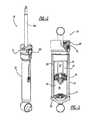
- FIG. 2is a perspective view of an example of the damper system
- FIG. 3is a partial cross-sectional view of the shock absorber of the damper system
- FIG. 4is an enlarged perspective view of a housing which houses an integrated electronic system
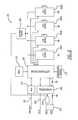
- FIG. 5is an example functional block diagram of the damper module
- FIG. 6illustrates a printed circuit board assembly (PCBA) disposed within the shock absorber
- FIG. 7is a cross-sectional view of the damper system with an enlarged view of a rod guide assembly having the PCBA;
- FIG. 8is an example block diagram of the PCBA
- FIG. 9illustrates an internal annular arrangement of the PCBA
- FIG. 10illustrates an internal vertical arrangement of the PCBA
- FIG. 11illustrates an inverted-wet arrangement of the PCBA
- FIG. 12illustrates an external arrangement of the PCBA
- FIG. 13illustrates a cap arrangement of the PCBA
- FIG. 14illustrates a damper system having a bumper cap arrangement of the PCBA
- FIG. 15is a perspective view of a bumper cap assembly of FIG. 14 disposed on a rod guide assembly of a shock absorber;
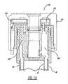
- FIG. 16is a partial cross-sectional view of FIG. 15 ;
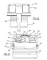
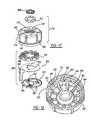
- FIG. 17is an exploded view of the bumper cap assembly of FIG. 15 ;
- FIG. 20is a perspective view of an integrated electronic assembly having a PCBA
- FIG. 21is a perspective view of a bumper cap assembly having solenoids.
- FIG. 22is a cross-sectional view of the bumper cap assembly of FIG. 21 .
- the vehicle 10includes a rear suspension 12 , a front suspension 14 , and a body 16 .
- the rear suspension 12has a transversely extending rear axle assembly (not shown) adapted to operatively support a pair of rear wheels 18 .
- the rear axle assemblyis attached to the body 16 by means of a pair of damper systems 20 and by a pair of springs 22 .
- the front suspension 14includes a transversely extending front axle assembly (not shown) to operatively support a pair of front wheels 24 .
- the front axle assemblyis attached to the body 16 by means of a pair of the damper systems 20 and by a pair of springs 26 .
- the damper systems 20serve to dampen the relative motion of the unsprung portion (i.e., front and rear suspensions 12 , 14 ) with respect to the sprung portion (i.e., body 16 ) of vehicle 10 .
- the damper system 20may be used with other types of vehicles or in other types of applications including, but not limited to, vehicles incorporating non-independent front and/or non-independent rear suspensions, vehicles incorporating independent front and/or independent rear suspensions or other suspension systems known in the art.
- the damper system 20may also be used on all wheeled and/or tracked vehicles.
- the damper system 20may be used on two and/or three wheels type of vehicles, such as motorcycles and all-terrain vehicles.
- the damper system 20includes an electrically adjustable hydraulic shock absorber 30 (“shock absorber 30 ” hereinafter) and a damper module (DM) 32 .
- the shock absorber 30may have a twin tube configuration.
- the shock absorber 30may include a pressure tube 36 , a piston assembly 38 , a piston rod 39 , a reserve tube 40 and a base valve assembly 42 .
- the damper system 20is described and depicted as including a twin tube electrically adjustable shock absorber. It is readily understood that the damper system 20 may include other types of electrically adjustable hydraulic shock absorber and is not limited to the shock absorber described herein.
- the damper system 20may include an electrically, adjustable shock absorber having a mono-tube configuration, a triple-tube configuration, or any other suitable shock absorber design known in the art.
- the shock absorberis connected to the sprung and unsprung portions of the vehicle as a non-inverted shock absorber. It is readily understood that the present disclosure is further applicable to inverted shock absorbers, which differ in the manner in which it is connected to the sprung and unsprung portions of vehicle.
- the pressure tube 36defines a working chamber 44 .
- the piston assembly 38is slidably disposed within the pressure tube 36 and divides the working chamber 44 into an upper working chamber 46 and a lower working chamber 48 .
- the piston rod 39is attached to the piston assembly 38 and extends through the upper working chamber 46 and through a rod guide assembly 50 which closes the upper end of the pressure tube 36 .
- the end of the piston rod 39 opposite to the piston assembly 38is adapted to be secured to the sprung mass of the vehicle 10 .
- Valving within the piston assembly 38controls the movement of fluid between the upper working chamber 46 and the lower working chamber 48 during movement of the piston assembly 38 within the pressure tube 36 . Since the piston rod 39 extends through the upper working chamber 46 and not the lower working chamber 48 , movement of the piston assembly 38 with respect to the pressure tube 36 causes a difference in the amount of fluid displaced in the upper working chamber 46 and the amount of fluid displaced in the lower working chamber 48 . The fluid displaced may flow through the base valve assembly 42 , the piston assembly 38 , or a combination thereof.
- the reserve tube 40surrounds the pressure tube 36 to define a fluid reservoir chamber 52 located between tubes 40 and 36 .
- the bottom end of the reserve tube 40is closed by a base cup 54 which can be connected to the unsprung mass of vehicle 10 .
- the upper end of reserve tube 40is attached to the rod guide assembly 50 .
- the base valve assembly 42is disposed between the lower working chamber 48 and the reservoir chamber 52 to control the flow of fluid between chambers 48 and 52 .
- an additional volume of fluidis needed in the lower working chamber 48 .
- fluidmay flow from the reservoir chamber 52 to the lower working chamber 48 through, for example, the base valve assembly 42 .
- shock absorber 30compresses in length, an excess of fluid must be removed from the lower working chamber 48 , and therefore, fluid may flow from the lower working chamber 48 to the reservoir chamber 52 through the base valve assembly 42 , the piston assembly 38 , or a combination thereof.
- the shock absorber 30may include one or more electromechanical valves 34 .
- the electromechanical valve 34may be a digital valve, a variable state valve, or other suitable electromechanical valves.
- the electromechanical valve 34may include a coil that controls the actuation of the electromechanical valve 34 . More particularly, when power is supplied to the electromechanical valve 34 , the coil creates a magnet field that actuates the electromechanical valve 34 .
- the actuation of the electromechanical valve 34controls the flow of fluid within the shock absorber 30 .
- the electromechanical valve 34may control the flow of fluid between the upper working chamber 46 and the reservoir chamber 52 .
- the electrically adjustable hydraulic shock absorberis provided as having an electromechanical valve 34
- the present disclosureis also applicable to electrically adjustable hydraulic shock absorbers that do not require an electromechanical valve.
- the present disclosureis applicable to an electrically adjustable hydraulic shock absorber that uses magneto-rheological and electro-rheological damping technologies.
- each damper system 20includes a DM that controls the operation of the shock absorber 30 , as described in further detail below.
- the DM 32may receive a damper setting from a master module 90 disposed in the vehicle 10 . More particularly, the DM 32 is communicably coupled to the master module 90 via a communication network. The master module 90 transmits data as an electronic signal via the communication network. The electronic signal may be an analog signal, a pulse width modulated (PWM) signal, CAN, LIN, or other type of signal/digital signal protocol known in the art. Based on the damper setting, the DM 32 controls the electromechanical valve(s) 34 disposed within the shock absorber 30 , such that the shock absorber 30 operates at a target damping state.
- PWMpulse width modulated
- the DM 32includes a signal module 102 , a damping state module 104 , a coil activation module 106 , and a diagnostic module 108 .
- the signal module 102decodes the electronic signal received from a device external of the DM 32 , such as the master module 90 .
- the signal module 102receives the damper setting from the master module 90 .
- the signal module 102may also transmit data to the device external of the DM 32 .
- the signal module 102may transmit data regarding a fault detected by the diagnostic module 108 . It is readily understood that the signal module 102 may receive an electronic signal from other devices external of the DM 32 , such as a switch, and is not limited to the master module 90 .
- the damping state module 104determines a control operation for operating the shock absorber 30 at the target damping state based on the data received from the signal module 102 . For example, based on the damper setting, the damping state module 104 determines a damping state of the shock absorber 30 and then controls actuation of the electromechanical valve 34 to operate the shock absorber 30 at the damping state determined. Similarly, if multiple electromechanical valves are disposed within the shock absorber 30 , the damping state module 104 determines the appropriate activation/deactivation of each of the valves 34 .
- the damping state module 104provides a control signal to the coil activation module 106 which in return controls the electrical power provided to a coil of the electromechanical valve 34 . More particularly, the coil activation module 106 determines the inputs for a coil drive, as discussed below.
- the diagnostic module 108monitors the operation of the coil activation module 106 and the electromechanical valve 34 for any faults/failures. If a fault is detected the diagnostic module 108 may notify the damping state module 104 . The damping state module 104 may then control the shock absorber 30 to a predetermined operation state.
- information regarding the faultmay also be transmitted to a device external of the DM 32 .
- the diagnostic module 108may transmit data regarding the fault to the signal module 102 which transmits the data to the master module 90 .
- the DM 32controls the damping state of the electrically adjustable hydraulic shock absorber 30 .
- the DM 32is disposed within the housing 100 as an integrated electronic system.
- the shock absorber 30includes a printed circuit board assembly (PCBA) 200 .
- the PCBA 200is disposed at the shock absorber 30 , and can be disposed within the housing 100 .
- the PCBA 200is disposed within the rod guide assembly 50 .
- the PCBA 200is an integrated electronic system that electrically powers coil(s) via coil drivers to create a magnetic field.
- the magnetic fieldactuates the electromechanical valve 34 (i.e., a hydraulic valve), thereby adjusting the damping characteristic of the shock absorber 30 .
- the PCBA 200includes a microcontroller 202 , coil drivers 204 A, 204 B, 204 C, and 204 D (hereinafter “coil drivers 204 A- 204 D”), and a transceiver 206 .
- the microcontroller 202performs the functions of the DM 32 . Specifically, microcontroller 202 performs the operation of the signal module 102 , the damping state module 104 , the coil activation module 106 , and the diagnostic module 108 .
- the microcontroller 202determines an input for each of the coil drivers 204 A- 204 D.
- the coil drivers 204 A- 204 Dcontrol current to, for example, the electromechanical valves based on the input (i.e., signal) from the microcontroller 202 . While in the example embodiment four coil drivers are shown, it is readily understood that one or more coil drivers may be used based on the number of electromechanical valves/coils disposed within the shock absorber 30 . Specifically, each electromechanical valve has a dedicated coil driver.
- the microcontroller 202may monitor the electrical current powering each electromechanical valve 34 as it responds to a command to change the damper setting. Accordingly, the microcontroller 202 can monitor the electrical current levels to insure that the electrical components, such as the coil drivers 204 A- 204 D and electromechanical valve coils, are working properly. Comparing the electrical current level to predetermined limits ensures coil drivers 204 A- 204 D (i.e., the power drive electronics) are not experiencing a fault such as a short circuit, open circuit, temperature extreme, or other fault.
- the transient current profilewhen recorded over time, can indicate the mechanical state of the electromechanical valve.
- the electromechanical valvemoves from the energized state to the unenergized state and vice versa, changes in the inductance of the electromechanical valve affect the electrical current. Inspection of this electrical current profile can, thus, determine the mechanical state of the electromechanical valve 34 as well as the electrical state.
- the transceiver 206may be provided as a LIN transceiver, CAN Bus, or Communication Bus.
- the transceivercommunicably couples the PCBA 200 to the communication bus provided as the communication link between the DM 32 and devices external of the DM 32 , such as the master module 90 .
- the communication busmay be a LIN bus 209 which is external of the PCBA 200 .
- the PCBA 200may also include a high side driver 208 , a PWM input 210 , a timer 212 , a voltage regulator 214 , a protection circuit 216 , and a temperature sensor 218 .
- the high side driver 208is electrically coupled to each of the coil drivers 204 A- 204 D.
- the high side driver 208acts like a master switch for controlling the power supply to each of the coil drivers 204 A- 204 D.
- the PWM input 210may be provided as an alternative communication link (reference number 222 in FIG. 8 ) for receiving an electronic signal from sensors/modules disposed external of the PCBA 200 .
- the timer 212may be a watchdog timer that monitors the operation of the microcontroller 202 and resets the microcontroller 202 if needed.
- the temperature sensor 218detects the ambient temperature of the PCBA 200 .
- the temperature sensor 218provides the information to the microcontroller 202 .
- the microcontroller 202may then determine the proper operation of the damper system 20 based on the temperature detected. Accordingly, the components disposed on the PCBA 200 are protected from extreme temperatures.
- the PCBA 200receives power from a vehicle battery.
- the voltage regulator 214conditions the electrical power from the vehicle battery to a voltage level suitable for the components on the PCBA 200 .
- the protection circuit 216may be provided as a battery line load dump transient and reverse voltage protection circuit. The protection circuit protects the components of the PCBA 200 from electrical transients which could damage or disrupt proper operation of the components on the PCBA 200 .
- the PCBA 200may couple to the power supply and the communication bus via a connector 201 ( FIG. 2 ).
- the connector 201may be configured to both electrically and communicably couple the PCBA 200 to the power supply and the communication bus, respectively.
- the PCBA 200may be coupled via two separate connectors. One for coupling to the power supply and the other to couple to the communication bus.
- FIGS. 9-13example methods of integrating the PCBA 200 with the shock absorber 30 are presented. It is readily understood that the present disclosure is not limited to the configuration shown in FIGS. 9-13 , and that other suitable configurations may be employed for integrating the PCBA 200 with the shock absorber 30 .
- an internal annular arrangement 300is presented.
- the PCBA 200is disposed within the rod guide assembly 50 .
- the PCBA 200has a ring-like structure, such that the piston rod 39 (not shown) may extend through the PCBA 200 .
- the annular arrangementis also represented in FIGS. 6 and 7 .
- the PCBA 200is directly coupled to the electromagnetic valve 34 .
- the coil driver 204 disposed on the PCBA 200is directly connected to the electromagnetic valve 34 , thereby eliminating the need of an electrical connector.
- an internal vertical arrangement 320is presented.
- the PCBA 200is arranged vertically (i.e., parallel with the piston rod 39 ) and within the rod guide assembly 50 .
- the PCBA 200is no longer limited to the annular shape.
- the PCBA 200may have a rectangular or square-like shape.
- a lead frame 250provides an electrical connection between the coil drivers 204 disposed on the PCBA 200 and the electromagnetic valve 34 . Therefore, the PCBA 200 is connected to the electromagnetic valve 34 by way of the lead frame 250 .
- an inverted-wet arrangement 340is presented.
- the PCBA 200is arranged between the pressure tube 36 and the reserve tube 40 .
- the PCBA 200may be disposed in the reservoir chamber 52 .
- Such a configurationis provided as “wet” since the PCBA 200 is in contact with hydraulic fluid.
- the pressure tube 36 and the reserve tube 40are not shown in FIG. 11 . While not shown in the figure, it is readily understood that the PCBA 200 is disposed in a housing that prevents the hydraulic fluid from entering the PCBA 200 .
- the lead frame 250couples the PCBA 200 to the electromechanical valve.
- the lead frame 250couples the coil driver 204 disposed on the PCBA 200 to an end of the electromagnetic valve 34 that is farthest from the rod guide assembly 50 .
- the configurationhas an inverted arrangement.
- an external arrangement 360is presented.
- the PCBA 200is arranged along an external surface of the shock absorber 30 .
- the PCBA 200can be disposed in a housing that protects the PCBA 200 from the environmental elements such as rain, humidity, debris, etc.
- the PCBA 200is then coupled to the electromechanical valve 34 via a lead frame 254 .
- a cap arrangement 380is presented.
- the PCBA 200is disposed within a cap 382 .
- the cap 382is positioned external to the shock absorber 30 . More particularly, the cap 382 is attached to an end of the shock absorber 30 .
- the PCBA 200is disposed in a gap 385 defined between the cap 382 and the shock absorber 30 .
- the PCBA 200can be disposed between the cap, the rod guide 384 , and the reserve tube 40 .
- the cap 382may or may not be a load bearing structure.
- the PCBA 200has a ring like structure, such that the piston rod 39 (not shown) may extend through both the PCBA 200 and the cap 382 .
- the PCBA 200is electrically coupled to an electromechanical valve disposed within a valve cavity 386 . Based on the distance between the PCBA 200 and the electromechanical valve, the PCBA 200 may be directly connected to the electromechanical valve or may be indirectly connected via, for example, a lead frame.
- FIGS. 14-20a bumper cap arrangement 500 is presented.
- the bumper cap arrangement 500has a PCBA arranged within a gap defined by a bumper cap which is a load bearing structure.
- FIG. 14shows a damper system 520 having the bumper cap arrangement 500 .
- the damper system 520is substantially similar to the damper system 20 . Accordingly, like numerals may be used to describe like features and components.
- a bumper cap assembly 600is attached to a shock absorber 530 .
- the bumper cap assembly 600is positioned between a rod guide assembly 550 of the shock absorber 530 and a jounce bumper 602 .
- the jounce bumper 602is a rubber or elastomeric component that is positioned on a piston rod 539 .
- the bumper cap assembly 600includes a bumper cap 604 , a dirt wiper 606 , and an electronic isolator assembly 608 .
- the electronic isolator assembly 608includes a gasket 610 , a PCBA 612 , and an isolator 614 .
- the bumper cap 604houses the electronic isolator assembly 608 ( FIG. 16 ).
- the bumper cap 604can be made of glass filed polyamide or polyphathlamide, and is a machined and/or molded component. The bumper cap 604 prevents metal to metal contact during severe jounce travel of the damping system 520 .
- the bumper cap 604has an annular cover 616 and a cylindrical body 618 .
- the annular cover 616defines an aperture 620 for receiving the piston rod 539 of the shock absorber 530 .
- a column 622extends from the aperture 620 .
- the bumper cap 604includes an outer shoulder 624 , an inner shoulder 626 , and multiple inner ribs 628 .
- the outer shoulder 624circumferentially extends from an inner surface 630 of the cylindrical body 618 .
- the outer shoulder 624abuts against the rod guide assembly 550 .
- the inner shoulder 626is formed at the end of the column 622 .
- a clearance gapis defined between the inner shoulder 626 and the rod guide assembly 550 of the shock absorber 530 .
- a compressive forceis exerted onto the bumper cap 604 .
- the inner shoulder 626moves downward and abuts against the rod guide assembly 550 , thereby eliminating the clearance gap.
- the inner ribs 628radially extend from the column 622 to the inner surface 630 of the cylindrical body 618 , and are disposed along an inner surface 632 of the annular cover 616 .
- the inner ribs 628provide a continuous transition between the inner shoulder 626 and the outer shoulder 624 .
- the inner ribs 628 , the inner shoulder 626 and the outer shoulder 624control the deflection of the bumper cap 604 , such that the bumper cap 604 does not collapse onto the electronic isolator assembly 608 disposed within. More particularly, the outer shoulder 624 maintains contact with the shock absorber 530 during loaded and unloaded operating conditions.
- the inner shoulder 626contacts the shock absorber 530 during loaded operating conditions.
- the inner ribs 628reinforce the cylindrical body 618 by distributing and absorbing compressive forces placed on the cylindrical body 618 .
- the bumper cap 604also includes a snap member 634 formed along an upper inner surface 635 of the cylindrical body 618 ( FIG. 18 ).
- the snap member 634aligns with and couples to a groove (not shown) defined around an outer surface of the shock absorber 530 .
- the groove and snap member 634form a snap-in feature used to attach the bumper cap 604 to the shock absorber 530 .
- the snap-in featureretains the bumper cap 604 on the shock absorber 530 during extreme thermal conditions.
- the bumper cap 604may be detached from the shock absorber 530 by simply decoupling the snap member 634 from the groove.
- the bumper cap 604can be attached to the shock absorber using various suitable fastening methods, and is not limited to the snap-in-feature.
- the bumper cap 604further defines a seal cavity 636 at the annular cover 616 , and includes a retainer 638 .
- the dirt wiper 606is positioned within the seal cavity 636 and is retained by the retainer 638 .
- the dirt wiper 606prevents water and dirt from entering the bumper cap 604 by creating a seal between the piston rod 539 and the bumper cap 604 .
- the retainer 638is fixedly attached to the cylindrical body 618 by way of, for example, ultra-sonic welding, adhesives, and/or other locking methods.
- the bumper cap 604may be purely one piece design in which the dirt wiper 606 is pressed fit into the seal cavity. Such one piece configuration removes the need for a separate component, but may require secondary machining operations of the seal cavity.
- the bumper cap 604defines a plurality of grooves 640 along an outer surface 642 of the annular cover 616 .
- the grooves 640extend radially outward from the aperture 620 .
- the grooves 640remove water and dirt that has been blocked by the dirt wiper 606 , thereby preventing the foreign debris from accumulating at the annular cover 616 .
- the groove 640also prevents air from being trapped between the jounce bumper 602 and the bumper cap 604 during deflection, thereby preventing noise or pressurization of the bumper cap interior.
- the bumper cap 604includes a plurality of outer ribs 644 protruding from an outer surface 646 of the cylindrical body 618 .
- the outer ribs 644extend along an axis parallel with a longitudinal axis of the cylindrical body 618 .
- the outer ribs 644reinforce the sides of the cylindrical body 618 . More particularly, the thickness of the cylindrical body 618 between the outer ribs 644 is thinner than at the outer ribs 644 . This allows the bumper cap 604 to stretch over the rod guide assembly 550 , while the outer ribs 644 restrain the sides of the cylindrical body 618 from expanding when compressive forces are placed on the bumper cap 604 .
- a lower seal 648is positioned at a brim 650 of the cylindrical body.
- the lower seal 648is an environmental seal that prevents debris from entering the bumper cap assembly 600 .
- the lower seal 648interfaces with an outer surface of the rod guide assembly 550 .
- the lower seal 648is provided as a separate component that is arranged within an opening 652 defined by the brim 650 .
- the bumper cap 604may include multiple lips, as the lower seal.
- the lipsare molded circumferentially along the inner surface 630 of the cylindrical body 618 at the brim 650 .
- the bumper cap 604receives the gasket 610 , the PCBA 612 , and the isolator 614 (i.e., the electronic isolator assembly 608 ) via the opening 652 .
- the gasket 610 , the PCBA 612 , and the isolator 614are disposed in a gap 654 defined by the annular cover 616 , the column 622 , and the cylindrical body 618 .
- the gasket 610holds and isolates the PCBA 612 . Specifically, the gasket 610 interfaces with an outer portion of the PCBA 612 to hold down the PCBA 612 and maintain the position of the PCBA 612 , such that the PCBA 612 does not move within the gap 654 .
- the PCBA 612is substantially similar to the PCBA 200 .
- the PCBA 612includes a connector 656 , which is substantially similar to connector 201 , and multiple terminals 658 .
- the terminals 658extend into the rod guide assembly 550 to engage with solenoids (not shown) of the digital valves 34 disposed in the rod guide assembly.
- the PCBA 612electrically powers the solenoids via coil drivers in order to actuate the electromagnetic valves 34 of the shock absorber 530 .
- the isolator 614isolates the vibrations experienced by the PCBA 612 , and also aligns the terminals 658 with the solenoids.
- the isolatorincludes a port 660 for each of the terminals 658 of the PCBA 612 .
- the ports 660receive and maintain the position of the terminals 658 .
- the ports 660align with the terminals of the solenoids disposed in the rod guide assembly 550 .
- the terminals 658are configured to receive the terminals of the solenoids.
- the isolator 614may include one or more tabs 662 that extend from an outer parameter of the isolator 614 .
- the bumper cap 604defines corresponding notches 664 which align with the tabs 662 .
- the tabs 662 and the notches 664also prevent the isolator 614 from moving within the gap 654 .
- the connector 656also acts as an alignment feature.
- the gasket 610includes a lid 666 which aligns with and covers the connector 656 .
- Isolator 614includes a bracket 668 which aligns and engages with the connector 656 .
- the bumper cap 604defines a slot 670 which aligns with and receives the connector 656 .
- the electronic isolator assemblyis provided as separate components which include the gasket 610 , the PCBA 612 , and the isolator 614 .
- the gasket 610 , the PCBA 612 , and the isolator 614may be encapsulated as a single component that is positioned in the bumper cap 604 .
- FIG. 20shows an integrated electronic isolator assembly 680 (“integrated assembly”, herein).
- the integrated assembly 680includes a PCBA which is encapsulated within a body 682 and a cord 684 extending from the connector 656 to a device external of the shock absorber.
- the body 682can be made of rubber or other suitable material.
- the body 682performs like a gasket and an isolator to support and isolate the PCBA disposed within.
- the integrated assembly 680simplifies assembly of the bumper cap assembly 600 , and eliminates the need for various alignment features, such as the notches 664 and the tabs 662 . Furthermore, the integrated assembly 680 protects the PCBA during assembly, and also provides additional structural support.
- the solenoids originally positioned within the rod guide assemblycan be part of the bumper cap assembly.
- the solenoids 692can be separate components that are attached to the terminals of the PCBA 612 via the isolator 614 .
- the rod guide assemblyis configured to receive the solenoids 692 .
- the solenoids 692can be part of the integrated assembly. Specifically, the solenoids are attached to the PCBA, and then the PCBA and solenoids are encapsulated within a body to form the integrated assembly.
- the bumper cap arrangement 500houses the PCBA within the bumper cap 604 which is load bearing structure.
- the bumper cap assembly 600includes two seals (e.g., the dirt wiper 606 and the lower seal 648 ) which prevent debris and water from entering the bumper cap 604 , thereby protecting the PCBA 612 .
- the interior space of the bumper cap 604is utilized to house the electronics of the damping system 520 , thereby creating a single unit that can be assembled onto the shock absorber 530 .
- the bumper cap 604is a rigid interface between the jounce bumper 602 and the body of the shock absorber and transfers loads to the body of the shock absorber during extreme jounce loads.
- the walls of the cylindrical bodyprovide structural support by alleviating bending stress placed on the column 622 and the inner ribs 628 .
- the compressive loadis evenly distributed between the cylindrical body 618 and the column 622 for optimum rigidity against loading.
- the outer ribs 644 provided along the outer wall of the cylindrical body 618prevent geometric instability in the bumper cap 604 by restraining the lower portion of the cylindrical body 618 from expanding, thereby reducing strain and radial deflection of the brim 650 of the bumper cap 604 and maintaining engagement with the shock absorber.
- the present disclosureis also applicable to electrically adjustable hydraulic shock absorbers that do not include an electromagnetic valve.
- the damping modulemay operate the shock absorber using known methods that utilize the magneto-rheological and electro-rheological damping technologies. Accordingly, instead of the electromechanical valve, the PCBA controls the current supplied to a coil disposed within the shock absorber.
- the PCBAis an integrated electronic system that electrically powers coil(s) to create a magnetic field.
- the magnetic fieldactuates the electromechanical valve (i.e., a hydraulic valve), thereby adjusting the damping characteristic of the shock absorber.
- the electromechanical valvei.e., a hydraulic valve
- each damper system 20includes its own power drive electronics for controlling the damping state of the shock absorber 30 .
- modulemay be replaced with the term circuit.
- the term modulemay refer to, be part of, or include an Application Specific Integrated Circuit (ASIC); a digital, analog, or mixed analog/digital discrete circuit; a digital, analog, or mixed analog/digital integrated circuit; a combinational logic circuit; a field programmable gate array (FPGA); a processor (shared, dedicated, or group) that executes code; memory (shared, dedicated, or group) that stores code executed by a processor; other suitable hardware components that provide the described functionality; or a combination of some or all of the above, such as in a system-on-chip.
- ASICApplication Specific Integrated Circuit
- FPGAfield programmable gate array
- Example embodimentsare provided so that this disclosure will be thorough, and will fully convey the scope to those who are skilled in the art. Numerous specific details are set forth such as examples of specific components, devices, and methods, to provide a thorough understanding of embodiments of the present disclosure. It will be apparent to those skilled in the art that specific details need not be employed, that example embodiments may be embodied in many different forms and that neither should be construed to limit the scope of the disclosure. In some example embodiments, well-known processes, well-known device structures, and well-known technologies are not described in detail.
- first, second, third, etc.may be used herein to describe various elements and/or components, these elements and/or components should not be limited by these terms. These terms may be only used to distinguish one element or component from another. Terms such as “first,” “second,” and other numerical terms when used herein do not imply a sequence or order unless clearly indicated by the context. Thus, a first element or component discussed could be termed a second element or component without departing from the teachings of the example embodiments.
- Spatially relative termssuch as “inner,” “outer,” “beneath,” “below,” “lower,” “above,” “upper,” and the like, may be used herein for ease of description to describe one element or feature's relationship to another element(s) or feature(s) as illustrated in the figures. Spatially relative terms may be intended to encompass different orientations of the device in use or operation in addition to the orientation depicted in the figures. For example, if the device in the figures is turned over, elements described as “below” or “beneath” other elements or features would then be oriented “above” the other elements or features. Thus, the example term “below” can encompass both an orientation of above and below. The device may be otherwise oriented (rotated 90 degrees or at other orientations) and the spatially relative descriptors used herein interpreted accordingly.
Landscapes
- Engineering & Computer Science (AREA)
- General Engineering & Computer Science (AREA)
- Mechanical Engineering (AREA)
- Physics & Mathematics (AREA)
- Electromagnetism (AREA)
- Microelectronics & Electronic Packaging (AREA)
- Vehicle Body Suspensions (AREA)
- Fluid-Damping Devices (AREA)
- Vibration Prevention Devices (AREA)
Abstract
Description
Claims (8)
Priority Applications (1)
| Application Number | Priority Date | Filing Date | Title |
|---|---|---|---|
| US14/303,943US9802456B2 (en) | 2013-02-28 | 2014-06-13 | Damper with integrated electronics |
Applications Claiming Priority (4)
| Application Number | Priority Date | Filing Date | Title |
|---|---|---|---|
| US201361770426P | 2013-02-28 | 2013-02-28 | |
| US14/193,879US9399383B2 (en) | 2013-02-28 | 2014-02-28 | Damper with integrated electronics |
| PCT/US2014/019534WO2014134500A1 (en) | 2013-02-28 | 2014-02-28 | Damper with integrated electronics |
| US14/303,943US9802456B2 (en) | 2013-02-28 | 2014-06-13 | Damper with integrated electronics |
Related Parent Applications (1)
| Application Number | Title | Priority Date | Filing Date |
|---|---|---|---|
| US14/193,879Continuation-In-PartUS9399383B2 (en) | 2013-02-28 | 2014-02-28 | Damper with integrated electronics |
Publications (3)
| Publication Number | Publication Date |
|---|---|
| US20150247544A1 US20150247544A1 (en) | 2015-09-03 |
| US20170276206A9 US20170276206A9 (en) | 2017-09-28 |
| US9802456B2true US9802456B2 (en) | 2017-10-31 |
Family
ID=56368673
Family Applications (2)
| Application Number | Title | Priority Date | Filing Date |
|---|---|---|---|
| US14/193,879Active2034-03-15US9399383B2 (en) | 2013-02-28 | 2014-02-28 | Damper with integrated electronics |
| US14/303,943Active2034-06-29US9802456B2 (en) | 2013-02-28 | 2014-06-13 | Damper with integrated electronics |
Family Applications Before (1)
| Application Number | Title | Priority Date | Filing Date |
|---|---|---|---|
| US14/193,879Active2034-03-15US9399383B2 (en) | 2013-02-28 | 2014-02-28 | Damper with integrated electronics |
Country Status (7)
| Country | Link |
|---|---|
| US (2) | US9399383B2 (en) |
| EP (1) | EP2962010B1 (en) |
| JP (1) | JP6346908B2 (en) |
| KR (1) | KR20150121020A (en) |
| CN (1) | CN105026788B (en) |
| BR (1) | BR112015020618A2 (en) |
| WO (1) | WO2014134500A1 (en) |
Cited By (1)
| Publication number | Priority date | Publication date | Assignee | Title |
|---|---|---|---|---|
| US10479160B2 (en) | 2017-06-06 | 2019-11-19 | Tenneco Automotive Operating Company Inc. | Damper with printed circuit board carrier |
Families Citing this family (36)
| Publication number | Priority date | Publication date | Assignee | Title |
|---|---|---|---|---|
| US8616351B2 (en) | 2009-10-06 | 2013-12-31 | Tenneco Automotive Operating Company Inc. | Damper with digital valve |
| USD745057S1 (en)* | 2012-04-03 | 2015-12-08 | Stealth Innovative Systems, Llc | Cylinder for pneumatic automotive lifting device |
| JP6346908B2 (en) | 2013-02-28 | 2018-06-20 | テネコ オートモティブ オペレーティング カンパニー インコーポレイテッドTenneco Automotive Operating Company Inc. | Damper with integrated electronic circuit |
| US9884533B2 (en) | 2013-02-28 | 2018-02-06 | Tenneco Automotive Operating Company Inc. | Autonomous control damper |
| US9217483B2 (en) | 2013-02-28 | 2015-12-22 | Tenneco Automotive Operating Company Inc. | Valve switching controls for adjustable damper |
| US9879746B2 (en) | 2013-03-15 | 2018-01-30 | Tenneco Automotive Operating Company Inc. | Rod guide system and method with multiple solenoid valve cartridges and multiple pressure regulated valve assemblies |
| BR112015023459A2 (en) | 2013-03-15 | 2017-07-18 | Tenneco Automotive Operating Co Inc | stem guide assembly with multi-piece valve assembly |
| US9879748B2 (en) | 2013-03-15 | 2018-01-30 | Tenneco Automotive Operating Company Inc. | Two position valve with face seal and pressure relief port |
| US9163691B2 (en) | 2013-03-15 | 2015-10-20 | Tenneco Automotive Operating Company Inc. | Rod guide arrangement for electronically controlled valve applications |
| JP6546424B2 (en)* | 2015-03-27 | 2019-07-17 | 株式会社ショーワ | Front fork |
| JP6417257B2 (en) | 2015-03-31 | 2018-11-07 | 株式会社ショーワ | Front fork |
| EP3702246B1 (en) | 2015-05-26 | 2025-10-08 | Exonetik Inc. | Active steering system using magnetorheological fluid clutch apparatuses |
| US20180319241A1 (en)* | 2015-06-30 | 2018-11-08 | Hitachi Automotive Systems, Ltd. | Suspension control apparatus |
| FR3046038B1 (en)* | 2015-12-24 | 2017-12-22 | Sagem Defense Securite | BACKPACK SUPPORT MODULE FOR A MODULAR STRUCTURE OF EXOSQUELET |
| CN105946493B (en)* | 2016-05-09 | 2018-10-30 | 安徽安凯汽车股份有限公司 | Bridge before car independence |
| ITUA20164223A1 (en)* | 2016-06-09 | 2017-12-09 | Sistemi Sospensioni Spa | Procedure for checking the correct closing of a double-tube hydraulic damper, particularly for vehicle suspension. |
| AU201613571S (en)* | 2016-07-07 | 2016-07-21 | Ironman 4 X 4 Pty Ltd | Shock Absorber |
| US10054182B2 (en)* | 2016-12-15 | 2018-08-21 | Tenneco Automotive Operating Company Inc. | Baffle tube for damper with electromechanical valve |
| US11007834B2 (en) | 2016-12-15 | 2021-05-18 | Tenneco Automotive Operating Company Inc. | Baffle tube for damper with electromechanical valve |
| EP3340259B1 (en)* | 2016-12-21 | 2019-09-25 | CPT Zwei GmbH | Solenoid device |
| US10393207B2 (en)* | 2017-03-21 | 2019-08-27 | Tenneco Automotive Operating Company Inc. | Damper with power drive electronics |
| JP2018161920A (en)* | 2017-03-24 | 2018-10-18 | 日立オートモティブシステムズ株式会社 | Suspension system |
| US10588233B2 (en)* | 2017-06-06 | 2020-03-10 | Tenneco Automotive Operating Company Inc. | Damper with printed circuit board carrier |
| US10987988B2 (en) | 2017-06-28 | 2021-04-27 | Tenneco Automotive Operating Company Inc. | Damper with volume reducing insert |
| JP2020142535A (en)* | 2017-06-28 | 2020-09-10 | 日立オートモティブシステムズ株式会社 | Suspension control device |
| JP6378413B1 (en)* | 2017-10-19 | 2018-08-22 | 株式会社ショーワ | Suspension device and recording medium |
| US10704641B2 (en) | 2017-12-15 | 2020-07-07 | Tenneco Automotive Operating Company Inc. | Baffle for damper with electromechanical valve |
| IT201800007584A1 (en)* | 2018-07-27 | 2020-01-27 | Sistemi Sospensioni Spa | Variable damping hydraulic shock absorber, particularly for vehicle suspension. |
| US11156262B2 (en) | 2019-02-01 | 2021-10-26 | Ace Controls Inc. | System to predict failures in shock absorbers |
| US10837515B2 (en)* | 2019-02-11 | 2020-11-17 | Tenneco Automotive Operating Company Inc. | Damper baffle tube with elastomeric skirt |
| CN110319139A (en)* | 2019-06-05 | 2019-10-11 | 西安理工大学 | A kind of machine tool feed direction vibration absorber |
| US20210131520A1 (en)* | 2019-11-01 | 2021-05-06 | Suspension Direct Inc. | Integrated electronic valving control for shock absorber |
| US11687070B2 (en) | 2020-08-12 | 2023-06-27 | Ace Controls Inc. | System and method for predicting shock absorber lifespan |
| US20230386717A1 (en)* | 2020-09-30 | 2023-11-30 | Hitachi Astemo, Ltd. | Solenoid, damping force adjustment mechanism, and damping force adjustable shock absorber |
| US12139275B2 (en)* | 2020-10-27 | 2024-11-12 | Safran Landing Systems Canada Inc. | Gas dissolution prediction system and method for an aircraft shock strut |
| US12350991B2 (en)* | 2021-11-18 | 2025-07-08 | Fox Factory, Inc. | Plug and play suspension |
Citations (302)
| Publication number | Priority date | Publication date | Assignee | Title |
|---|---|---|---|---|
| US2409349A (en) | 1945-10-22 | 1946-10-15 | Nevin S Focht | Hydraulic shock absorber |
| US2473043A (en) | 1944-08-28 | 1949-06-14 | Monroe Auto Equipment Co | Shock absorber structure |
| US3896908A (en) | 1973-05-04 | 1975-07-29 | Triple S Ind Inc | Shock absorbing apparatus |
| US3945474A (en) | 1975-01-20 | 1976-03-23 | Monroe Auto Equipment Company | Shock absorber |
| US4317105A (en) | 1979-05-02 | 1982-02-23 | Brajnandan Sinha | Condition indicating device for wheeled vehicle shock absorbers |
| US4352417A (en) | 1980-10-03 | 1982-10-05 | Ford Motor Company | Control valve for shock absorber pistons and the like |
| GB2123922A (en) | 1982-06-15 | 1984-02-08 | Tokico Ltd | Hydraulic damper with adjustable flow path |
| US4468050A (en) | 1983-08-15 | 1984-08-28 | Woods Lonnie K | Computer optimized adaptive suspension system |
| DE3406875A1 (en) | 1984-02-25 | 1985-09-05 | Boge Gmbh, 5208 Eitorf | VIBRATION DAMPER FOR VEHICLES |
| US4552324A (en) | 1983-05-31 | 1985-11-12 | Pneumo Corporation | Landing gear mechanism for use on rough runways |
| DE3518858A1 (en) | 1984-05-28 | 1985-11-28 | Nissan Motor Co., Ltd., Yokohama, Kanagawa | Shock absorber with a device for length measurement |
| US4564214A (en) | 1983-03-18 | 1986-01-14 | Mazda Motor Corporation | Suspension system for motor vehicle having variable suspension characteristics |
| DE3432465A1 (en) | 1984-09-04 | 1986-03-13 | Boge Gmbh, 5208 Eitorf | ADJUSTABLE DAMPING VALVE FOR A HYDRAULIC VIBRATION DAMPER |
| US4589528A (en) | 1982-08-26 | 1986-05-20 | Fichtel & Sachs Ag | Double-tube vibration damper |
| US4591186A (en) | 1983-10-20 | 1986-05-27 | Tokico Ltd. | Hydraulic shock absorbing device of adjustable damping force type |
| JPS61125907A (en) | 1984-11-22 | 1986-06-13 | Mitsubishi Motors Corp | Electronic-controlled suspension equipment |
| DE3518327A1 (en) | 1985-05-22 | 1986-11-27 | Boge Gmbh, 5208 Eitorf | HYDRAULIC, ADJUSTABLE VIBRATION DAMPER |
| US4696489A (en) | 1985-01-14 | 1987-09-29 | Nissan Motor Company, Limited | Automotive suspension system with variable damping characteristics |
| JPS62253506A (en) | 1986-04-28 | 1987-11-05 | Kayaba Ind Co Ltd | Damping force control method for vehicle |
| US4726453A (en) | 1983-04-11 | 1988-02-23 | F & O Elektronik Systems Gmbh & Co. | Self-adjusting single- or twin-tube shock absorber |
| US4776437A (en) | 1986-10-31 | 1988-10-11 | Atsugi Motor Parts Company, Limited | Variable damping force shock absorber with rotary actuator for rotary member |
| US4788489A (en) | 1985-07-12 | 1988-11-29 | Nissan Motor Co., Ltd. | Position sensor for use in variable height automotive suspension or the like |
| JPS6467408A (en) | 1987-09-04 | 1989-03-14 | Nippon Denso Co | Shock absorber control device |
| US4846317A (en) | 1987-08-25 | 1989-07-11 | Trw Inc. | Strut with controlled variable damping rate |
| US4850460A (en) | 1987-04-13 | 1989-07-25 | Boge Ag | Hydraulic adjustable shock absorber |
| US4867476A (en) | 1987-07-03 | 1989-09-19 | Aisin Seiki Kabushiki Kaisha | Shock absorber unit |
| US4872537A (en) | 1988-06-06 | 1989-10-10 | Brian Warner | Adjustable damper means for shock absorber |
| US4892328A (en) | 1988-05-27 | 1990-01-09 | Aura Systems, Inc. | Electromagnetic strut assembly |
| US4909536A (en) | 1988-10-24 | 1990-03-20 | Monroe Auto Equipment | Electronic height sensor |
| US4913457A (en) | 1987-11-06 | 1990-04-03 | Pfister GmbH and Bayrische Motoren Werke AG | Method and apparatus for optimizing the driving characteristics of a vehicle |
| US4943083A (en) | 1989-03-13 | 1990-07-24 | Monroe Auto Equipment Company | Signal conditioning circuit assembly |
| US4958706A (en) | 1988-11-14 | 1990-09-25 | Richardson Donald G | Adjustable shock absorbers |
| US4969662A (en) | 1989-06-08 | 1990-11-13 | Aura Systems, Inc. | Active damping system for an automobile suspension |
| US4973854A (en) | 1987-11-28 | 1990-11-27 | Herman Hemscheidt Maschinenfabrik Gmbh & Co. | Hydraulic shock-absorber and vibration damper with adjustable damping |
| US4984819A (en) | 1988-04-14 | 1991-01-15 | Atsugi Motor Parts Company, Limited | Automotive suspension system and shock absorber therefor |
| US4986393A (en) | 1988-02-09 | 1991-01-22 | Boge Ag | Adjustable vibration dampers for motor vehicles |
| US4988967A (en) | 1988-08-26 | 1991-01-29 | Borg-Warner Automotive Electronic & Mechanical Systems Corporation | Solenoid operated hydraulic control valve |
| DE3928343A1 (en) | 1989-08-26 | 1991-02-28 | Dirk Prof Dr Ing Jansen | Vehicular active suspension damper with digital signal processor - identifies natural oscillator behaviour and estimates excitations from roadway for desired damping by electrical-operated valves |
| US5038613A (en) | 1989-05-19 | 1991-08-13 | Matsushita Electric Industrial Co., Ltd. | Angular rate detecting device |
| US5058715A (en) | 1988-11-28 | 1991-10-22 | Ilan Silberstein | Shock absorber |
| US5067743A (en) | 1989-08-28 | 1991-11-26 | Toyota Jidosha Kabushiki Kaisha | Pressure control system for suspension |
| US5092626A (en) | 1989-03-13 | 1992-03-03 | Monroe Auto Equipment Company | Apparatus for controlling the damping of a shock absorber |
| US5106053A (en) | 1988-08-26 | 1992-04-21 | Borg-Warner Automotive Electronic & Mechanical Systems Corporation | Solenoid operated hydraulic control valve |
| US5123671A (en) | 1989-03-13 | 1992-06-23 | Monroe Auto Equipment Company | Method and apparatus for controlling shock absorbers |
| DE4041619A1 (en) | 1990-12-22 | 1992-06-25 | Bosch Gmbh Robert | CYLINDER |
| US5133574A (en) | 1988-11-18 | 1992-07-28 | Atsugi Unisia Corporation | Variable damping characteristics suspension system for automotive suspension system with variable damping characteristics shock absorber with input vibration frequency dependent variation characteristics |
| US5133434A (en) | 1989-06-15 | 1992-07-28 | Atsugi Unisia Corporation | Variable damping force shock absorber with feature of independent adjustment of damping characteristics for bounding a rebounding strokes |
| US5143185A (en) | 1988-08-11 | 1992-09-01 | Alfred Teves Gmbh | Controllable hydraulic vibration damper for automotive vehicles |
| US5154442A (en) | 1990-11-19 | 1992-10-13 | Milliken Douglas L | Self-contained acceleration-responsive adaptive damper |
| WO1992018788A1 (en) | 1991-04-17 | 1992-10-29 | Monroe Auto Equipment Company | High pressure sealing system and method |
| US5160162A (en) | 1990-03-21 | 1992-11-03 | Aisin Seiki Kabushiki Kaisha | Shock absorber producing variable damping force |
| US5189614A (en) | 1989-07-06 | 1993-02-23 | Aisin Seiki K.K. | Vehicle shock absorbing system |
| US5200895A (en) | 1989-12-13 | 1993-04-06 | Atsugi Unisia Corporation | Automotive suspension system with enhanced response characteristics |
| US5242190A (en) | 1990-12-24 | 1993-09-07 | Ford Motor Company | Unitary sensor assembly for automotive vehicles |
| JPH0626546A (en) | 1992-07-06 | 1994-02-01 | Kayaba Ind Co Ltd | Hydraulic shock absorber |
| US5293968A (en) | 1991-12-03 | 1994-03-15 | Robert Bosch Gmbh | Dual-tube shock absorber |
| US5299488A (en) | 1991-08-07 | 1994-04-05 | Microhydraulics Inc. | Active suspension system |
| US5337863A (en) | 1986-06-05 | 1994-08-16 | Monroe Auto Equipment Company | Method and apparatus for absorbing mechanical shock |
| US5350187A (en) | 1992-10-16 | 1994-09-27 | Monroe Auto Equipment Company | Adjustable damping system |
| US5350983A (en) | 1992-12-21 | 1994-09-27 | Ford Motor Company | Suspension damper with integrated controls |
| US5360089A (en) | 1992-05-21 | 1994-11-01 | Unisia Jecs Corporation | Automotive suspension control system utilizing variable damping force shock absorber |
| US5360230A (en) | 1990-11-30 | 1994-11-01 | Aisin Seiki Kabushiki Kaisha | Damping force control device for suspension system |
| US5363945A (en) | 1988-08-01 | 1994-11-15 | Monroe Auto Equipment Company | Control valve for shock absorbers |
| US5383679A (en) | 1992-03-04 | 1995-01-24 | Unisia Jecs Corporation | Arrangement of suspension system for automotive vehicle |
| US5390121A (en) | 1993-08-19 | 1995-02-14 | Lord Corporation | Banded on-off control method for semi-active dampers |
| JPH0756311A (en) | 1993-08-20 | 1995-03-03 | Konica Corp | Device for replenishing solid processing agent for processing photosensitive material |
| US5396973A (en) | 1991-11-15 | 1995-03-14 | Lord Corporation | Variable shock absorber with integrated controller, actuator and sensors |
| US5404973A (en) | 1993-03-08 | 1995-04-11 | Tokico Ltd. | Damping force control type hydraulic shock absorber |
| JPH07113434A (en) | 1993-10-18 | 1995-05-02 | Kayaba Ind Co Ltd | Adjustable damping force shock absorber |
| US5430648A (en) | 1992-03-03 | 1995-07-04 | Unisia Jecs Corporation | Vehicular suspension system |
| US5435421A (en) | 1992-11-07 | 1995-07-25 | Fichtel & Sachs Ag | Hydraulic, adjustable vibration damper and a valve system for a hydraulic, adjustable vibration damper |
| US5439085A (en) | 1990-08-06 | 1995-08-08 | Fichtel & Sachs Ag | Oscillation damper |
| US5485417A (en) | 1991-01-31 | 1996-01-16 | Fichtel & Sachs Ag | Process and arrangement for controlling a vibration damper |
| US5487455A (en) | 1992-02-29 | 1996-01-30 | Itt Automotive Europe Gmbh | Variable flow valve with position sensor |
| US5488556A (en) | 1993-03-22 | 1996-01-30 | Unisia Jecs Corporation | Apparatus and method for independently controlling damping force characteristic of vehicular shock absorber |
| US5497325A (en) | 1992-08-31 | 1996-03-05 | Fuji Jukogyo Kabushiki Kaisha | Suspension control system for a vehicle |
| US5497862A (en) | 1994-02-22 | 1996-03-12 | Unisia Jecs Corporation | Hydraulic shock absorber having variable damping force characteristic structure |
| US5532921A (en) | 1993-09-28 | 1996-07-02 | Toyota Jidosha Kabushiki Kaisha | Electric control apparatus for shock absorber |
| JPH08260747A (en) | 1995-03-20 | 1996-10-08 | Kayaba Ind Co Ltd | Damping device for vibration control of structures |
| US5570762A (en) | 1994-10-27 | 1996-11-05 | Delphi Automotive Systems Russelsheim Gmbh | Hydraulic damper |
| US5577579A (en) | 1995-10-30 | 1996-11-26 | General Motors Corporation | Method of manufacturing a suspension damper |
| US5590898A (en) | 1989-06-15 | 1997-01-07 | Group Lotus Plc | Vehicle suspension system |
| US5597054A (en) | 1992-09-29 | 1997-01-28 | Showa Corporation | Hydraulic damper |
| US5632503A (en) | 1995-12-19 | 1997-05-27 | Ford Motor Company | Method for allowing enhanced driver selection of suspension damping and steering efforts |
| US5638275A (en) | 1994-02-24 | 1997-06-10 | Unisia Jecs Corporation | Apparatus and method for controlling damping force characteristic of vehicular shock absorber |
| US5653315A (en) | 1994-03-21 | 1997-08-05 | Monroe Auto Equipment Company | Automatic damper system |
| US5655633A (en) | 1994-05-20 | 1997-08-12 | Tokico Ltd. | Hydraulic damper of a damping force adjusting type |
| US5656315A (en) | 1994-10-13 | 1997-08-12 | Advanced Food Technologies, Inc. | Method for impregnating porous material with liquid flavoring |
| US5657840A (en) | 1986-06-05 | 1997-08-19 | Lizell; Magnus B. | Method and apparatus for absorbing mechanical shock |
| JPH09217779A (en) | 1996-02-15 | 1997-08-19 | Tokico Ltd | Hydraulic shock absorber |
| US5690195A (en) | 1996-07-29 | 1997-11-25 | General Motors Corporation | Alternating state pressure regulation valved damper |
| US5725239A (en) | 1996-03-26 | 1998-03-10 | Monroe Auto Equipment | Adaptive load dependent suspension system |
| US5775470A (en) | 1991-11-18 | 1998-07-07 | Itt Automotive Europe Gmbh | Hydraulic controllable vibration absorber |
| US5803482A (en) | 1995-09-30 | 1998-09-08 | Hyundai Motor Company | Shock absorber for automotive suspension |
| US5833036A (en) | 1996-03-20 | 1998-11-10 | Pro-Formance Shocks, Inc. | Rebound adjustable shock absorber |
| US5845672A (en) | 1996-12-10 | 1998-12-08 | General Motors Corporation | Solenoid coil positioning assembly |
| US5860497A (en) | 1997-06-12 | 1999-01-19 | Hks Co., Ltd. | Hydraulic shock absorber with removable components |
| US5878851A (en) | 1996-07-02 | 1999-03-09 | Lord Corporation | Controllable vibration apparatus |
| US5890081A (en) | 1995-07-06 | 1999-03-30 | Unisia Jecs Corporation | Automotive vehicle suspension control system |
| US5913391A (en) | 1997-01-09 | 1999-06-22 | Avm, Inc. | Damper |
| US5934421A (en) | 1995-12-20 | 1999-08-10 | Tokico Ltd. | Damping force control type hydraulic shock absorber |
| US5937976A (en) | 1996-04-19 | 1999-08-17 | Mannesmann Sachs Ag | Vibration damper with restrictor plate |
| US5950775A (en) | 1997-08-12 | 1999-09-14 | Achmad; Muchlis | In-tube shock absorber mounted electromagnetically operated damper valve and shock absorber including adapter |
| US5967268A (en) | 1997-03-17 | 1999-10-19 | Tenneco Automotive Inc. | Temperature responsive damper |
| US5987369A (en) | 1996-10-31 | 1999-11-16 | Mando Machinery Corporation | System and method of controlling semiactive suspension |
| US6003644A (en) | 1995-07-11 | 1999-12-21 | Yamaha Hatsudoki Kabushiki Kaisha | Damping force variable hydraulic shock absorber |
| US6036500A (en) | 1998-07-17 | 2000-03-14 | General Motors Corporation | Electrical connection system for a selectably adjustable ride strut |
| DE19853277C1 (en) | 1998-11-18 | 2000-05-04 | Krupp Bilstein Gmbh | Controllable valve system for hydraulic vibration dampers in automobiles comprises damper having an electromagnetic valve which can be switched into at least three switch positions |
| US6092011A (en) | 1997-04-08 | 2000-07-18 | Unisia Jecs Corporation | Apparatus and method for controlling damping force characteristic of vehicular shock absorber |
| US6095489A (en) | 1997-03-14 | 2000-08-01 | Smc Corporation | Double- or single-solenoid type selector valve encapsulated in resin |
| US6105740A (en) | 1997-07-23 | 2000-08-22 | Marzocchi S.P.A. | Hydraulic shock absorber |
| US6109400A (en) | 1997-07-09 | 2000-08-29 | Mannesmann Boge Gmbh | Impact absorber |
| US6135250A (en) | 1997-06-04 | 2000-10-24 | Mannesmann Sachs Ag | Hydropneumatic vibration damper of variable damping force |
| US6155391A (en) | 1998-03-31 | 2000-12-05 | Tokico Ltd. | Hydraulic shock absorber of a dumping force adjustable type |
| DE10025399A1 (en) | 1999-05-25 | 2000-12-21 | Tenneco Automotive Inc | Vibration damper |
| US6213262B1 (en) | 1999-02-01 | 2001-04-10 | Gabriel Ride Control Products, Inc. | Shock absorber |
| US6273224B1 (en) | 1997-08-12 | 2001-08-14 | Hr Textron, Inc. | Shock absorber mounted electromagnetically operated damper valve |
| US6296091B1 (en) | 1998-11-11 | 2001-10-02 | Kenmar Company Trust | Suspension control unit and control valve |
| US6298958B1 (en) | 1999-09-21 | 2001-10-09 | Hyundai Motor Company | Automatically adjustable damping force shock absorber |
| US6302248B1 (en) | 1998-12-24 | 2001-10-16 | Tokico Ltd. | Damping force control type hydraulic shock absorber |
| US6343677B2 (en) | 1999-02-01 | 2002-02-05 | Gabriel Ride Control Products, Inc. | Shock absorber |
| US6427986B1 (en) | 1999-03-31 | 2002-08-06 | Tokico, Ltd. | Air suspension apparatus |
| US20020133277A1 (en) | 2001-01-05 | 2002-09-19 | You-Seok Koh | Apparatus for controlling semi-active suspension system |
| US6460664B1 (en) | 2000-05-22 | 2002-10-08 | Tenneco Automotive Inc. | Independently tunable variable bleed orifice |
| US6464053B1 (en) | 1999-07-26 | 2002-10-15 | Tenneco Automotive Operating Company, Inc. | Single piece piston |
| CN1094855C (en) | 1999-03-19 | 2002-11-27 | 萱场工业株式会社 | Shock absorber using using for transverse runout vibration absorption of stock and damping method |
| JP2002349630A (en) | 2001-05-31 | 2002-12-04 | Tokico Ltd | Friction control hydraulic shock absorber and suspension control device |
| US6496761B1 (en) | 1999-01-18 | 2002-12-17 | Yamaha Hatsudoki Kabushiki Kaisha | Optimization control method for shock absorber |
| US6533294B1 (en) | 1999-11-26 | 2003-03-18 | Delphi Technologies, Inc. | Vehicle roll control system |
| US6588726B2 (en) | 2001-07-13 | 2003-07-08 | Eaton Corporation | Load bearing solenoid operated valve and method of making same |
| US20030164193A1 (en) | 1999-04-23 | 2003-09-04 | Zheng David Lou | Solenoid operated hydraulic control valve |
| US6616124B2 (en) | 2001-03-07 | 2003-09-09 | Delphi Technologies, Inc. | Spool valve for controlled dampers |
| US20030192755A1 (en) | 2002-04-16 | 2003-10-16 | Barbison James M. | Shock absorber with toroidal solenoid adjustable damping |
| US6651787B2 (en) | 2000-08-23 | 2003-11-25 | Mannesmann Sachs Ag | Vibration damper |
| US6655512B2 (en) | 2000-12-19 | 2003-12-02 | Delphi Technologies, Inc. | Variable area low speed orifice in a vehicle damper |
| US6672436B1 (en) | 2000-04-19 | 2004-01-06 | Tenneco Automotive Operating Company Inc. | Variable bleed orifice valving |
| US6707290B2 (en) | 1996-03-22 | 2004-03-16 | Mts Systems Corporation | Magnetostrictive linear displacement transducer for a vehicle strut suspension |
| DE10238657A1 (en) | 2002-08-23 | 2004-03-18 | Daimlerchrysler Ag | Spring system for motor vehicles has a shock absorber with sectional areas interlinked by a hydraulic circuit and switching valves in branches of the hydraulic circuit |
| US6708803B2 (en) | 2002-06-10 | 2004-03-23 | Mark Andrew Jensen | Self-leveling dual spring rate strut |
| US20040090020A1 (en) | 2002-11-08 | 2004-05-13 | Arctic Cat, Inc. | Electronically controlled active suspension damper |
| US20040154887A1 (en) | 2002-11-27 | 2004-08-12 | Nehl Thomas W. | Suspension control system and related damper with integrated local controller and sensors |
| US6782980B2 (en) | 2001-11-29 | 2004-08-31 | Tokico Ltd. | Controllable damping force hydraulic shock absorber |
| US20040199313A1 (en) | 2003-04-01 | 2004-10-07 | Delphi Technologies Inc. | Acceleration enhancement algorithm |
| US6814193B2 (en) | 2002-05-24 | 2004-11-09 | Zf Sachs Ag | Vibration damper with a hydraulic pressure stop |
| US20050001472A1 (en) | 2003-07-02 | 2005-01-06 | Paul Bale | Control network for vehicle dynamics and ride control systems having distributed electronic control units |
| US6851528B2 (en) | 2001-10-29 | 2005-02-08 | Bombardier Recreational Products Inc. | Shock absorber with adjustable valving |
| US20050029063A1 (en) | 2003-07-24 | 2005-02-10 | Baltic Electronik Gmbh | Shock absorber having variable damping characteristics and method of damping vibrations with the shock absorber |
| US20050056504A1 (en) | 2003-09-17 | 2005-03-17 | David Holiviers | Adjustable damper with control valve, mounted in an external collar |
| US20050056502A1 (en) | 2003-09-15 | 2005-03-17 | Mario Maes | Integrated tagging system for an electronic shock absorber |
| US20050061593A1 (en) | 2003-09-22 | 2005-03-24 | Degronckel Dirk | Adjustable damper with valve mounted in-line |
| US6879898B2 (en) | 2003-01-03 | 2005-04-12 | General Motors Corporation | Method and apparatus for vehicle integrated chassis control system |
| US20050085969A1 (en) | 2003-10-15 | 2005-04-21 | Mando Corporation | Method for controlling damping force in an electronically-controlled suspension apparatus |
| US20050113997A1 (en) | 2003-11-23 | 2005-05-26 | Mando Corporation | Electronically-controlled suspension apparatus and damping force control method |
| US6904344B2 (en) | 2002-01-11 | 2005-06-07 | Activeshock, Inc. | Semi-active shock absorber control system |
| US20050173849A1 (en) | 2004-02-10 | 2005-08-11 | Bart Vandewal | Electronically controlled frequency dependent damping |
| EP1588072A1 (en) | 2003-01-31 | 2005-10-26 | Arvin Technologies | Integrated damping adjustment valve |
| US6959797B2 (en) | 2000-09-26 | 2005-11-01 | Stabilus Gmbh | Piston-cylinder assembly with braking device |
| US6978872B2 (en) | 2002-05-29 | 2005-12-27 | Progressive Suspension Inc. | Hydraulic dampers with pressure regulated control valve |
| US20060038149A1 (en) | 2003-10-28 | 2006-02-23 | Zf Friedrichshafen Ag | Valve assembly with an integrated circuit arrangement |
| US7032912B2 (en) | 2002-11-27 | 2006-04-25 | S.N.R. Roulements | Rotating instrumented suspension stop for measuring vertical forces |
| CN1267611C (en) | 2003-04-11 | 2006-08-02 | 简安德烈亚斯阿德里安·克鲁格 | Rainwater Harvesting and Filling Systems |
| US20060219503A1 (en) | 2005-03-29 | 2006-10-05 | Mando Corporation | Air suspension and electronically controlled suspension system |
| EP1746302A1 (en) | 2004-04-26 | 2007-01-24 | Kayaba Industry Co., Ltd. | Hydraulic shock absorber |
| US7168709B2 (en) | 2002-09-25 | 2007-01-30 | Aisin Aw Co., Ltd. | Suspension control apparatus of vehicle |
| US20070034466A1 (en) | 2005-08-15 | 2007-02-15 | Tenneco Automotive Operating Company, Inc. | Asymmetrical intake damper valve |
| US20070051574A1 (en) | 2005-09-02 | 2007-03-08 | Tenneco Automotive Operating Company, Inc. | Rod guide seal |
| US7214103B2 (en) | 2003-11-25 | 2007-05-08 | Eaton Corporation | Connecting a solenoid to a lead frame |
| US7234574B2 (en) | 2003-02-05 | 2007-06-26 | Kajima Corporation | Damping coefficient switching-type hydraulic damper |
| US7234707B2 (en) | 2002-05-31 | 2007-06-26 | Kelsey-Hayes Company | Integrated control unit for an active roll control system for a vehicle suspension system |
| CN101025213A (en) | 2006-02-20 | 2007-08-29 | 株式会社万都 | Damping force control valve and shock absorber using the same |
| US7273138B2 (en) | 2004-02-03 | 2007-09-25 | Mando Corporation | Damping force variable valve and shock absorber using same |
| US7286919B2 (en) | 2005-10-17 | 2007-10-23 | Gm Global Technology Operations, Inc. | Method and apparatus for controlling damping of a vehicle suspension |
| US20070255466A1 (en) | 2006-04-28 | 2007-11-01 | Shui-Chuan Chiao | Daming adjusting/controlling system for wireless adjustment of shock-absorbers for vehicle |
| US7318595B2 (en) | 2004-05-27 | 2008-01-15 | Cnh America Llc | Variable ride control |
| US20080054537A1 (en) | 2003-10-03 | 2008-03-06 | Andrew Colin Harrison | Air Suspension Unit and System |
| CN100381728C (en) | 2004-02-19 | 2008-04-16 | 郭川 | Pressure controlled variable damping vibration attenuator |
| US7374028B2 (en) | 2003-07-08 | 2008-05-20 | Fox Factory, Inc. | Damper with pressure-sensitive compression damping |
| US7389994B2 (en) | 2004-01-27 | 2008-06-24 | Hadley Products | Vehicle leveling system |
| CN101229765A (en) | 2007-01-25 | 2008-07-30 | 通用汽车环球科技运作公司 | Multistage jounce bumper |
| US7416189B2 (en) | 2005-02-17 | 2008-08-26 | Spartan Motors Chassis, Inc. | Vehicle ride control system |
| US20080243336A1 (en) | 2006-05-09 | 2008-10-02 | Fitzgibbons Patrick J | Mobility Traction Control System and Method |
| US20080250844A1 (en) | 2007-04-02 | 2008-10-16 | Gartner Bill J | Methods and Apparatus for Developing a Vehicle Suspension |
| US20080264743A1 (en) | 2007-04-26 | 2008-10-30 | Lee Dong-Rak | Damper equipped with relative displacement detecting sensor |
| US7475538B2 (en) | 2005-11-29 | 2009-01-13 | Elton Daniel Bishop | Digital Hydraulic system |
| US7493995B2 (en) | 2004-07-14 | 2009-02-24 | Tenneco Automotive Operating Company, Inc. | Shock absorber with integrated displacement sensor |
| US20090071772A1 (en) | 2007-09-17 | 2009-03-19 | S & T Daewoo Co.,Ltd | Sensor module comprising acceleration sensor and relative displacement sensor, damper and electronically controllable suspension system comprising the same, and method of controlling vehicle movement using the same |
| US20090078517A1 (en) | 2007-09-26 | 2009-03-26 | Showa Corporation | Damping force adjusting structure of hydraulic shock absorber |
| US20090084647A1 (en) | 2007-09-27 | 2009-04-02 | Showa Corporation | Damping force adjusting structure of hydraulic shock absorber |
| US20090132122A1 (en) | 2007-11-21 | 2009-05-21 | Mando Corporation | Shock absorber for controlling damping force characteristics |
| US20090192673A1 (en) | 2008-01-24 | 2009-07-30 | Cannondale Bicycle Corporation | Bicycle user interface system and method of operation thereof |
| US20090200125A1 (en) | 2005-06-14 | 2009-08-13 | Ohlins Racing Ab | Arrangement, device and method at a disturbance-eliminating valve for damper |
| US20090200503A1 (en) | 2008-02-13 | 2009-08-13 | Mando Corporation | Solenoid valve assembly of variable damping force damper and method of assembling the same |
| DE112007002377T5 (en) | 2006-10-11 | 2009-08-20 | Tenneco Automotive Operating Company Inc., Lake Forest | Shock absorber with infinitely variable semi-active valve |
| EP2105330A1 (en) | 2008-03-26 | 2009-09-30 | Honda Motor Co., Ltd. | Control device for a wheel suspension system |
| US7604101B2 (en) | 2006-02-20 | 2009-10-20 | Mando Corporation | Damping force control valve and shock absorber using the same |
| US7611000B2 (en) | 2007-09-14 | 2009-11-03 | Showa Corporation | Damping force adjusting structure of hydraulic shock absorber |
| US7621538B2 (en) | 2005-05-28 | 2009-11-24 | Bfs Diversified Products, Llc | Air spring assembly with localized signal processing, system and method utilizing same, as well as operating module therefor |
| US20100001217A1 (en) | 2008-07-03 | 2010-01-07 | Mando Corporation | Damping force variable valve of shock absorber |
| US7644933B2 (en) | 2006-02-13 | 2010-01-12 | Firestone Industrial Products Company, Llc | Vehicle suspension system and method |
| US7654369B2 (en) | 2008-05-20 | 2010-02-02 | Husco International, Inc. | Hydraulic vibration damper piston with an integral electrically operated adjustment valve |
| US7654370B2 (en) | 2007-02-02 | 2010-02-02 | Arvin Technologies, Inc. | Shock absorber with integrated position sensor |
| US20100044172A1 (en) | 2008-08-21 | 2010-02-25 | Mando Corporation | Damping force variable valve of shock absorber |
| US7680573B2 (en) | 2003-09-26 | 2010-03-16 | Aisin Aw Co., Ltd. | Suspension control system and suspension control method for vehicle |
| WO2010029133A1 (en)* | 2008-09-11 | 2010-03-18 | Continental Automotive Gmbh | Method for producing a valve control unit and valve control unit, shock absorber and motor vehicle comprising a valve control unit |
| US20100066051A1 (en) | 2008-08-25 | 2010-03-18 | Haugen David M | Methods and apparatus for suspension lock out and signal generation |
| US20100109276A1 (en) | 2006-05-01 | 2010-05-06 | Marjoram Robert H | Controllable vehicle suspension system with magneto-rheological fluid device |
| US7722405B2 (en) | 2004-11-26 | 2010-05-25 | Siemens Aktiengesellschaft | Electronic device |
| US20100138116A1 (en) | 2006-10-30 | 2010-06-03 | Air Lift Company | Modular control system |
| US20100163354A1 (en) | 2006-08-09 | 2010-07-01 | Sigmund Braun | Damper |
| US20100181154A1 (en) | 2009-01-19 | 2010-07-22 | Y.S.S. (Thailand) Co., Ltd. | Advanced triple piston damper |
| US20100191420A1 (en) | 2007-09-21 | 2010-07-29 | Motohiko Honma | Damping force control apparatus for vehicle |
| US7775333B2 (en) | 2005-07-20 | 2010-08-17 | The Hong Kong Polytechnic University | Magnetorheological damper and use thereof |
| US20100211253A1 (en) | 2007-10-10 | 2010-08-19 | Universidade De Tras-Os-Montes E Alto Douro | Intelligent continuous monitoring system for application in shock absorbers |
| CN201575099U (en) | 2009-12-29 | 2010-09-08 | 深圳市德平国瀚汽车电子科技有限公司 | Controllable extension and retract shock absorber |
| CN201575100U (en) | 2009-12-29 | 2010-09-08 | 深圳市德平国瀚汽车电子科技有限公司 | Controllable extension and retract shock absorber |
| CN101857035A (en) | 2009-04-10 | 2010-10-13 | 萱场工业株式会社 | Linear shock absorbers for railway vehicles |
| US20100276906A1 (en) | 2009-05-04 | 2010-11-04 | Mario Galasso | Suspension system for a vehicle |
| CN201636258U (en) | 2010-04-08 | 2010-11-17 | 长春孔辉汽车科技有限公司 | Electric control adjustable damping shock absorber |
| US20100301578A1 (en) | 2009-05-28 | 2010-12-02 | Kenji Noda | Cylinder apparatus |
| US7849983B2 (en) | 2006-05-01 | 2010-12-14 | Lord Corporation | Controllable vehicle suspension system with a controllable magnetorheological fluid strut |
| US20100326267A1 (en) | 2009-06-30 | 2010-12-30 | Hata Hideki | Hydraulic cylinder |
| CN201705852U (en) | 2010-04-08 | 2011-01-12 | 长春孔辉汽车科技有限公司 | Electric control type variable damping vibration absorber |
| US7878311B2 (en) | 2007-07-19 | 2011-02-01 | Husco Automotive Holdings, LLC | Piston with an integral electrically operated adjustment valve for a hydraulic vibration damper |
| US20110035091A1 (en) | 2009-08-05 | 2011-02-10 | Hitachi Cable, Ltd. | Sensor system for motion control of a moving unit and a method of installing a sensor system for motion control of a moving unit |
| US7896311B2 (en) | 2007-01-30 | 2011-03-01 | Mando Corporation | Solenoid valve of shock absorber |
| US20110056783A1 (en) | 2009-01-23 | 2011-03-10 | Kayaba Industry Co., Ltd. | Shock absorbing device |
| US7912603B2 (en) | 2004-03-22 | 2011-03-22 | Continental Teves Ag & Co., Ohg | Method for controlling the damper force in vehicles having a ride level control system |
| US20110079475A1 (en) | 2009-10-06 | 2011-04-07 | Tenneco Automotive Operating Company Inc. | Damper with digital valve |
| US7926513B2 (en) | 2006-09-21 | 2011-04-19 | Denso Corporation | Spool valve |
| US7931282B2 (en) | 2009-06-19 | 2011-04-26 | GM Global Technology Operations LLC | Automatically variable ride height adjustment apparatus |
| CN102032306A (en) | 2009-09-30 | 2011-04-27 | 萱场工业株式会社 | Hydraulic circuit for semi-active damper |
| US20110101579A1 (en) | 2009-10-30 | 2011-05-05 | Great Lakes Sound & Vibration, Inc. | Multi-Stage Telescopic Shock Absorber |
| US7942248B2 (en) | 2002-12-31 | 2011-05-17 | Lord Corporation | Adjustable damping control with end stop |
| CN102076988A (en) | 2008-06-25 | 2011-05-25 | 奥林斯赛车公司 | A pressure regulator for a shock absorber valve |
| US20110153157A1 (en) | 2008-07-07 | 2011-06-23 | Zf Friedrichshafen Ag | Wheel suspension for a vehicle |
| US7967116B2 (en) | 2007-12-10 | 2011-06-28 | Enidine, Inc. | Load compensating hydraulic rate control |
| US7967117B2 (en) | 2005-12-22 | 2011-06-28 | Showa Corporation | Suspension spring adjusting apparatus of hydraulic shock absorber |
| CN102109024A (en) | 2009-12-29 | 2011-06-29 | 深圳市德平国瀚汽车电子科技有限公司 | Electronic control shock absorber |
| US7997394B2 (en) | 2007-03-30 | 2011-08-16 | Hitachi, Ltd. | Damping force adjustable fluid pressure shock absorber |
| US20110198172A1 (en) | 2010-02-16 | 2011-08-18 | Whan Jee Young | Damping force variable valve of a shock absorber |
| US20110214956A1 (en) | 2009-01-07 | 2011-09-08 | John Marking | Remotely operated bypass for a suspension damper |
| US20110240424A1 (en) | 2010-03-30 | 2011-10-06 | Zf Friedrichshafen Ag | Vibration Damper with Integrated Level Control |
| US8056392B2 (en) | 2007-12-31 | 2011-11-15 | Jri Development Group, Llc | Method, system, and device for optimizing a vehicle's suspension |
| US20110298399A1 (en) | 2009-07-08 | 2011-12-08 | Toyota Jidosha Kabushiki Kaisha | Damper system for vehicle |
| US8075002B1 (en) | 2008-11-18 | 2011-12-13 | Am General Llc | Semi-active suspension system |
| US20120018263A1 (en) | 2009-01-07 | 2012-01-26 | John Marking | Suspension damper with remotely-operable valve |
| CN102345700A (en) | 2011-09-15 | 2012-02-08 | 常州格林电力机械制造有限公司 | Nuclear-grade large equipment damper |
| US8113521B2 (en) | 2009-06-19 | 2012-02-14 | Pin Hsiu Rubber Co., Ltd. | Intelligent electronic air suspension system that automatically adjusts its air pressure |
| US8116939B2 (en) | 2008-05-27 | 2012-02-14 | Toyota Jidosha Kabushiki Kaisha | Suspension system for vehicle |
| US20120048665A1 (en) | 2009-01-07 | 2012-03-01 | John Marking | Compression isolator for a suspension damper |
| US8132654B2 (en) | 2008-05-02 | 2012-03-13 | Bwi Company Limited S.A. | Hydraulic damper with compensation chamber |
| US20120073918A1 (en) | 2010-09-29 | 2012-03-29 | Makoto Nishimura | Shock absorber |
| US20120073920A1 (en) | 2010-09-29 | 2012-03-29 | Jin Yamasaki | Shock absorber |
| US8160774B2 (en) | 2008-10-15 | 2012-04-17 | GM Global Technology Operations LLC | Vehicular actuator system |
| US8214106B2 (en) | 2008-04-02 | 2012-07-03 | GM Global Technology Operations LLC | Adaptive suspension control for a motor vehicle |
| US20120181126A1 (en) | 2009-09-29 | 2012-07-19 | Koni B.V. | Adjustable shock absorber |
| US20120186922A1 (en) | 2011-01-25 | 2012-07-26 | Dt Swiss Inc. | Shock Absorber for a Bicycle |
| US20120228072A1 (en) | 2007-04-16 | 2012-09-13 | Tenneco Automotive Operating Company Inc | Shock absorber having a continuously variable valve with base line valving |
| US8267382B2 (en) | 2007-10-31 | 2012-09-18 | Hitachi, Ltd. | Method of assembling a hydraulic shock absorber and hydraulic shock absorber |
| US8275515B2 (en) | 2007-12-12 | 2012-09-25 | Honeywell International Inc. | Shock absorber health and condition monitoring device |
| US20120305349A1 (en) | 2011-05-31 | 2012-12-06 | Hiroshi Murakami | Shock absorber |
| US20130081913A1 (en) | 2011-10-04 | 2013-04-04 | Tenneco Automotive Operating Company Inc. | Welding of transfer ring on round tube |
| US20130090808A1 (en) | 2011-02-22 | 2013-04-11 | Charles Lemme | Multi-function damper system |
| US8430217B2 (en) | 2007-06-04 | 2013-04-30 | Robert Bosch Gmbh | Damper |
| CN103154562A (en) | 2010-12-17 | 2013-06-12 | Zf腓特烈斯哈芬股份公司 | Adjustable damping valve device |
| CN103168183A (en) | 2010-10-22 | 2013-06-19 | 奥林斯赛车公司 | Valve arrangement |
| CN103244495A (en) | 2013-04-26 | 2013-08-14 | 武汉理工大学 | Electrical control rectifying valve of hydraulic electric feed energy shock absorber |
| US8525453B2 (en) | 2009-07-08 | 2013-09-03 | Toyota Jidosha Kabushiki Kaisha | Damper system for vehicle |
| US20130228401A1 (en) | 2010-11-20 | 2013-09-05 | Zf Friedrichshafen Ag | Vibration damper having a sensor device |
| CN203186023U (en) | 2013-03-14 | 2013-09-11 | 上海汽车集团股份有限公司 | Commercial vehicle suspension lowering device |
| US20130234379A1 (en) | 2009-01-19 | 2013-09-12 | Y.S.S. (Thailand) Co., Ltd. | Advanced triple piston damper |
| US20130275003A1 (en) | 2011-01-31 | 2013-10-17 | Toru Uchino | Suspension control apparatus |
| US8567575B2 (en) | 2006-11-15 | 2013-10-29 | Mando Corporation | Shock absorber having self pumping unit |
| US20130313057A1 (en) | 2012-05-23 | 2013-11-28 | Showa Corporation | Hydraulic shock absorber |
| CN103429929A (en) | 2011-03-02 | 2013-12-04 | 本田技研工业株式会社 | Damper with variable damping force |
| US20130328277A1 (en) | 2012-06-08 | 2013-12-12 | Msi Defense Solutions, Llc | Electronically adjustable damper and system |
| US20130341842A1 (en) | 2011-02-01 | 2013-12-26 | Norbert Weber | Hydropneumatic piston/cylinder arrangement |
| US20130340865A1 (en) | 2012-06-21 | 2013-12-26 | Thomas Manger | Adjustable damping valve arrangement |
| US20130345933A1 (en) | 2012-06-25 | 2013-12-26 | Russ Lee Norton | Ride Performance Optimization In An Active Suspension System |
| US8666596B2 (en) | 2007-10-26 | 2014-03-04 | Volkswagen Ag | Method and system for manipulating the movement of a vehicle body of a motor vehicle controllable or adjustable with respect to its movement processes and vehicle |
| CN103702888A (en) | 2011-07-28 | 2014-04-02 | 日立汽车系统株式会社 | Damper for railway vehicles |
| US8695766B2 (en) | 2011-03-31 | 2014-04-15 | Hitachi Automotive Systems, Ltd. | Shock absorber |
| CN203548687U (en) | 2013-10-12 | 2014-04-16 | 安徽工程大学 | Adjustable-damping shock absorber of automobile |
| US20140125018A1 (en) | 2012-11-07 | 2014-05-08 | Polaris Industries Inc. | Vehicle having suspension with continuous damping control |
| CN103946095A (en) | 2012-03-14 | 2014-07-23 | 萱场工业株式会社 | Damping devices for railway vehicles |
| US20140202808A1 (en) | 2013-01-22 | 2014-07-24 | Kyntec Corporation | Shock absorber with variable damping profile |
| US8794405B2 (en) | 2010-12-28 | 2014-08-05 | Hitachi Automotive Systems, Ltd. | Damping force control type shock absorber |
| US20140231200A1 (en) | 2011-09-21 | 2014-08-21 | Shigeo Katayama | Shock absorber |
| US20140244112A1 (en) | 2013-02-28 | 2014-08-28 | Tenneco Automotive Operating Company Inc. | Valve switching controls for adjustable damper |
| US20140238797A1 (en)* | 2013-02-28 | 2014-08-28 | Tenneco Automotive Operating Company Inc. | Damper with integrated electronics |
| US20140239602A1 (en) | 2013-02-28 | 2014-08-28 | Tenneco Automotive Operating Company Inc. | Autonomous control damper |
| US20140265169A1 (en) | 2013-03-15 | 2014-09-18 | Levant Power Corporation | Integrated active suspension smart valve |
| US20140262654A1 (en) | 2013-03-15 | 2014-09-18 | Tenneco Automotive Operating Company Inc. | Two position valve with face seal and pressure relief port |
| US20140262648A1 (en) | 2013-03-15 | 2014-09-18 | Tenneco Automotive Operating Company Inc. | Rod guide assembly with multi-piece valve assembly |
| US20140262652A1 (en) | 2013-03-15 | 2014-09-18 | Tenneco Automotive Operating Company Inc. | Rod guide arrangement for electronically controlled valve applications |
| US20140284156A1 (en) | 2013-03-22 | 2014-09-25 | Mando Corporation | Damping force variable valve assembly and damping force variable shock absorber having the same |
| US8844687B2 (en) | 2011-06-09 | 2014-09-30 | Mando Corporation | Valve structure of shock absorber having variable flow channel |
| CN104074909A (en) | 2013-03-29 | 2014-10-01 | 株式会社昭和 | Hydraulic shock absorbing apparatus |
| US20140297116A1 (en) | 2013-03-15 | 2014-10-02 | Levant Power Corporation | Self-driving vehicle with integrated active suspension |
| US20140291090A1 (en) | 2013-03-28 | 2014-10-02 | Showa Corporation | Hydraulic shock absorber |
| US20140303844A1 (en) | 2013-04-08 | 2014-10-09 | Ford Global Technologies, Llc | Device and method for proactive control of a vibration damping system of a vehicle |
| US20150088379A1 (en) | 2013-09-20 | 2015-03-26 | Hitachi Automotive Systems, Ltd. | Suspension system |
Family Cites Families (5)
| Publication number | Priority date | Publication date | Assignee | Title |
|---|---|---|---|---|
| JPS61125907U (en) | 1985-01-24 | 1986-08-07 | ||
| JPS61266842A (en)* | 1985-05-20 | 1986-11-26 | Ckd Controls Ltd | Electromagnetic drive device for controlling orifice area of shock absorber |
| JPH0626546Y2 (en) | 1988-04-28 | 1994-07-20 | 愛知車輌株式会社 | Safety equipment for work vehicles |
| JPH0899514A (en)* | 1994-09-30 | 1996-04-16 | Kayaba Ind Co Ltd | shock absorber |
| US5996745A (en)* | 1997-05-15 | 1999-12-07 | K-2 Corporation | Piezoelectric shock absorber valve |
- 2014
- 2014-02-28JPJP2015560364Apatent/JP6346908B2/ennot_activeExpired - Fee Related
- 2014-02-28EPEP14756361.3Apatent/EP2962010B1/enactiveActive
- 2014-02-28BRBR112015020618Apatent/BR112015020618A2/ennot_activeIP Right Cessation
- 2014-02-28KRKR1020157023799Apatent/KR20150121020A/ennot_activeAbandoned
- 2014-02-28USUS14/193,879patent/US9399383B2/enactiveActive
- 2014-02-28CNCN201480010828.3Apatent/CN105026788B/enactiveActive
- 2014-02-28WOPCT/US2014/019534patent/WO2014134500A1/enactiveApplication Filing
- 2014-06-13USUS14/303,943patent/US9802456B2/enactiveActive
Patent Citations (341)
| Publication number | Priority date | Publication date | Assignee | Title |
|---|---|---|---|---|
| US2473043A (en) | 1944-08-28 | 1949-06-14 | Monroe Auto Equipment Co | Shock absorber structure |
| US2409349A (en) | 1945-10-22 | 1946-10-15 | Nevin S Focht | Hydraulic shock absorber |
| US3896908A (en) | 1973-05-04 | 1975-07-29 | Triple S Ind Inc | Shock absorbing apparatus |
| US3945474A (en) | 1975-01-20 | 1976-03-23 | Monroe Auto Equipment Company | Shock absorber |
| US4317105A (en) | 1979-05-02 | 1982-02-23 | Brajnandan Sinha | Condition indicating device for wheeled vehicle shock absorbers |
| US4352417A (en) | 1980-10-03 | 1982-10-05 | Ford Motor Company | Control valve for shock absorber pistons and the like |
| GB2123922A (en) | 1982-06-15 | 1984-02-08 | Tokico Ltd | Hydraulic damper with adjustable flow path |
| US4589528A (en) | 1982-08-26 | 1986-05-20 | Fichtel & Sachs Ag | Double-tube vibration damper |
| US4564214A (en) | 1983-03-18 | 1986-01-14 | Mazda Motor Corporation | Suspension system for motor vehicle having variable suspension characteristics |
| US4726453A (en) | 1983-04-11 | 1988-02-23 | F & O Elektronik Systems Gmbh & Co. | Self-adjusting single- or twin-tube shock absorber |
| US4552324A (en) | 1983-05-31 | 1985-11-12 | Pneumo Corporation | Landing gear mechanism for use on rough runways |
| US4468050A (en) | 1983-08-15 | 1984-08-28 | Woods Lonnie K | Computer optimized adaptive suspension system |
| US4591186A (en) | 1983-10-20 | 1986-05-27 | Tokico Ltd. | Hydraulic shock absorbing device of adjustable damping force type |
| GB2154700A (en) | 1984-02-25 | 1985-09-11 | Boge Gmbh | Control of dampers for vehicle suspension |
| DE3406875A1 (en) | 1984-02-25 | 1985-09-05 | Boge Gmbh, 5208 Eitorf | VIBRATION DAMPER FOR VEHICLES |
| DE3518858A1 (en) | 1984-05-28 | 1985-11-28 | Nissan Motor Co., Ltd., Yokohama, Kanagawa | Shock absorber with a device for length measurement |
| US4749070A (en) | 1984-09-04 | 1988-06-07 | Boge Gmbh | Hydraulic vibration damper having adjustable damping valve |
| DE3432465A1 (en) | 1984-09-04 | 1986-03-13 | Boge Gmbh, 5208 Eitorf | ADJUSTABLE DAMPING VALVE FOR A HYDRAULIC VIBRATION DAMPER |
| JPS61125907A (en) | 1984-11-22 | 1986-06-13 | Mitsubishi Motors Corp | Electronic-controlled suspension equipment |
| US4696489A (en) | 1985-01-14 | 1987-09-29 | Nissan Motor Company, Limited | Automotive suspension system with variable damping characteristics |
| DE3518327A1 (en) | 1985-05-22 | 1986-11-27 | Boge Gmbh, 5208 Eitorf | HYDRAULIC, ADJUSTABLE VIBRATION DAMPER |
| US4723640A (en) | 1985-05-22 | 1988-02-09 | Boge Gmbh | Adjustable hydraulic vibration damper |
| US4788489A (en) | 1985-07-12 | 1988-11-29 | Nissan Motor Co., Ltd. | Position sensor for use in variable height automotive suspension or the like |
| JPS62253506A (en) | 1986-04-28 | 1987-11-05 | Kayaba Ind Co Ltd | Damping force control method for vehicle |
| US5337863A (en) | 1986-06-05 | 1994-08-16 | Monroe Auto Equipment Company | Method and apparatus for absorbing mechanical shock |
| US5657840A (en) | 1986-06-05 | 1997-08-19 | Lizell; Magnus B. | Method and apparatus for absorbing mechanical shock |
| US4776437A (en) | 1986-10-31 | 1988-10-11 | Atsugi Motor Parts Company, Limited | Variable damping force shock absorber with rotary actuator for rotary member |
| US4850460A (en) | 1987-04-13 | 1989-07-25 | Boge Ag | Hydraulic adjustable shock absorber |
| US4867476A (en) | 1987-07-03 | 1989-09-19 | Aisin Seiki Kabushiki Kaisha | Shock absorber unit |
| US4846317A (en) | 1987-08-25 | 1989-07-11 | Trw Inc. | Strut with controlled variable damping rate |
| JPS6467408A (en) | 1987-09-04 | 1989-03-14 | Nippon Denso Co | Shock absorber control device |
| US4913457A (en) | 1987-11-06 | 1990-04-03 | Pfister GmbH and Bayrische Motoren Werke AG | Method and apparatus for optimizing the driving characteristics of a vehicle |
| US4973854A (en) | 1987-11-28 | 1990-11-27 | Herman Hemscheidt Maschinenfabrik Gmbh & Co. | Hydraulic shock-absorber and vibration damper with adjustable damping |
| US4986393A (en) | 1988-02-09 | 1991-01-22 | Boge Ag | Adjustable vibration dampers for motor vehicles |
| US4984819A (en) | 1988-04-14 | 1991-01-15 | Atsugi Motor Parts Company, Limited | Automotive suspension system and shock absorber therefor |
| US4892328A (en) | 1988-05-27 | 1990-01-09 | Aura Systems, Inc. | Electromagnetic strut assembly |
| US4872537A (en) | 1988-06-06 | 1989-10-10 | Brian Warner | Adjustable damper means for shock absorber |
| US5363945A (en) | 1988-08-01 | 1994-11-15 | Monroe Auto Equipment Company | Control valve for shock absorbers |
| US5143185A (en) | 1988-08-11 | 1992-09-01 | Alfred Teves Gmbh | Controllable hydraulic vibration damper for automotive vehicles |
| US4988967A (en) | 1988-08-26 | 1991-01-29 | Borg-Warner Automotive Electronic & Mechanical Systems Corporation | Solenoid operated hydraulic control valve |
| US5106053A (en) | 1988-08-26 | 1992-04-21 | Borg-Warner Automotive Electronic & Mechanical Systems Corporation | Solenoid operated hydraulic control valve |
| US4909536A (en) | 1988-10-24 | 1990-03-20 | Monroe Auto Equipment | Electronic height sensor |
| US4958706A (en) | 1988-11-14 | 1990-09-25 | Richardson Donald G | Adjustable shock absorbers |
| US5133574A (en) | 1988-11-18 | 1992-07-28 | Atsugi Unisia Corporation | Variable damping characteristics suspension system for automotive suspension system with variable damping characteristics shock absorber with input vibration frequency dependent variation characteristics |
| US5058715A (en) | 1988-11-28 | 1991-10-22 | Ilan Silberstein | Shock absorber |
| US5092626A (en) | 1989-03-13 | 1992-03-03 | Monroe Auto Equipment Company | Apparatus for controlling the damping of a shock absorber |
| US4943083A (en) | 1989-03-13 | 1990-07-24 | Monroe Auto Equipment Company | Signal conditioning circuit assembly |
| US5123671A (en) | 1989-03-13 | 1992-06-23 | Monroe Auto Equipment Company | Method and apparatus for controlling shock absorbers |
| US5038613A (en) | 1989-05-19 | 1991-08-13 | Matsushita Electric Industrial Co., Ltd. | Angular rate detecting device |
| US4969662A (en) | 1989-06-08 | 1990-11-13 | Aura Systems, Inc. | Active damping system for an automobile suspension |
| US5590898A (en) | 1989-06-15 | 1997-01-07 | Group Lotus Plc | Vehicle suspension system |
| US5133434A (en) | 1989-06-15 | 1992-07-28 | Atsugi Unisia Corporation | Variable damping force shock absorber with feature of independent adjustment of damping characteristics for bounding a rebounding strokes |
| US5189614A (en) | 1989-07-06 | 1993-02-23 | Aisin Seiki K.K. | Vehicle shock absorbing system |
| DE3928343A1 (en) | 1989-08-26 | 1991-02-28 | Dirk Prof Dr Ing Jansen | Vehicular active suspension damper with digital signal processor - identifies natural oscillator behaviour and estimates excitations from roadway for desired damping by electrical-operated valves |
| US5067743A (en) | 1989-08-28 | 1991-11-26 | Toyota Jidosha Kabushiki Kaisha | Pressure control system for suspension |
| US5200895A (en) | 1989-12-13 | 1993-04-06 | Atsugi Unisia Corporation | Automotive suspension system with enhanced response characteristics |
| US5160162A (en) | 1990-03-21 | 1992-11-03 | Aisin Seiki Kabushiki Kaisha | Shock absorber producing variable damping force |
| US5439085A (en) | 1990-08-06 | 1995-08-08 | Fichtel & Sachs Ag | Oscillation damper |
| US5154442A (en) | 1990-11-19 | 1992-10-13 | Milliken Douglas L | Self-contained acceleration-responsive adaptive damper |
| US5360230A (en) | 1990-11-30 | 1994-11-01 | Aisin Seiki Kabushiki Kaisha | Damping force control device for suspension system |
| US5285878A (en) | 1990-12-22 | 1994-02-15 | Robert Bosch Gmbh | Cylinder including a piston with a valve control |
| DE4041619A1 (en) | 1990-12-22 | 1992-06-25 | Bosch Gmbh Robert | CYLINDER |
| US5242190A (en) | 1990-12-24 | 1993-09-07 | Ford Motor Company | Unitary sensor assembly for automotive vehicles |
| US5485417A (en) | 1991-01-31 | 1996-01-16 | Fichtel & Sachs Ag | Process and arrangement for controlling a vibration damper |
| WO1992018788A1 (en) | 1991-04-17 | 1992-10-29 | Monroe Auto Equipment Company | High pressure sealing system and method |
| US5299488A (en) | 1991-08-07 | 1994-04-05 | Microhydraulics Inc. | Active suspension system |
| US5396973A (en) | 1991-11-15 | 1995-03-14 | Lord Corporation | Variable shock absorber with integrated controller, actuator and sensors |
| US5775470A (en) | 1991-11-18 | 1998-07-07 | Itt Automotive Europe Gmbh | Hydraulic controllable vibration absorber |
| US5293968A (en) | 1991-12-03 | 1994-03-15 | Robert Bosch Gmbh | Dual-tube shock absorber |
| US5487455A (en) | 1992-02-29 | 1996-01-30 | Itt Automotive Europe Gmbh | Variable flow valve with position sensor |
| US5430648A (en) | 1992-03-03 | 1995-07-04 | Unisia Jecs Corporation | Vehicular suspension system |
| US5383679A (en) | 1992-03-04 | 1995-01-24 | Unisia Jecs Corporation | Arrangement of suspension system for automotive vehicle |
| US5360089A (en) | 1992-05-21 | 1994-11-01 | Unisia Jecs Corporation | Automotive suspension control system utilizing variable damping force shock absorber |
| JPH0626546A (en) | 1992-07-06 | 1994-02-01 | Kayaba Ind Co Ltd | Hydraulic shock absorber |
| US5497325A (en) | 1992-08-31 | 1996-03-05 | Fuji Jukogyo Kabushiki Kaisha | Suspension control system for a vehicle |
| US5597054A (en) | 1992-09-29 | 1997-01-28 | Showa Corporation | Hydraulic damper |
| US5350187A (en) | 1992-10-16 | 1994-09-27 | Monroe Auto Equipment Company | Adjustable damping system |
| US5435421A (en) | 1992-11-07 | 1995-07-25 | Fichtel & Sachs Ag | Hydraulic, adjustable vibration damper and a valve system for a hydraulic, adjustable vibration damper |
| US5350983A (en) | 1992-12-21 | 1994-09-27 | Ford Motor Company | Suspension damper with integrated controls |
| US5404973A (en) | 1993-03-08 | 1995-04-11 | Tokico Ltd. | Damping force control type hydraulic shock absorber |
| US5488556A (en) | 1993-03-22 | 1996-01-30 | Unisia Jecs Corporation | Apparatus and method for independently controlling damping force characteristic of vehicular shock absorber |
| US5390121A (en) | 1993-08-19 | 1995-02-14 | Lord Corporation | Banded on-off control method for semi-active dampers |
| JPH0756311A (en) | 1993-08-20 | 1995-03-03 | Konica Corp | Device for replenishing solid processing agent for processing photosensitive material |
| US5532921A (en) | 1993-09-28 | 1996-07-02 | Toyota Jidosha Kabushiki Kaisha | Electric control apparatus for shock absorber |
| JPH07113434A (en) | 1993-10-18 | 1995-05-02 | Kayaba Ind Co Ltd | Adjustable damping force shock absorber |
| US5497862A (en) | 1994-02-22 | 1996-03-12 | Unisia Jecs Corporation | Hydraulic shock absorber having variable damping force characteristic structure |
| US5638275A (en) | 1994-02-24 | 1997-06-10 | Unisia Jecs Corporation | Apparatus and method for controlling damping force characteristic of vehicular shock absorber |
| US5653315A (en) | 1994-03-21 | 1997-08-05 | Monroe Auto Equipment Company | Automatic damper system |
| US5655633A (en) | 1994-05-20 | 1997-08-12 | Tokico Ltd. | Hydraulic damper of a damping force adjusting type |
| US5656315A (en) | 1994-10-13 | 1997-08-12 | Advanced Food Technologies, Inc. | Method for impregnating porous material with liquid flavoring |
| US5570762A (en) | 1994-10-27 | 1996-11-05 | Delphi Automotive Systems Russelsheim Gmbh | Hydraulic damper |
| JPH08260747A (en) | 1995-03-20 | 1996-10-08 | Kayaba Ind Co Ltd | Damping device for vibration control of structures |
| US5890081A (en) | 1995-07-06 | 1999-03-30 | Unisia Jecs Corporation | Automotive vehicle suspension control system |
| US6003644A (en) | 1995-07-11 | 1999-12-21 | Yamaha Hatsudoki Kabushiki Kaisha | Damping force variable hydraulic shock absorber |
| US5803482A (en) | 1995-09-30 | 1998-09-08 | Hyundai Motor Company | Shock absorber for automotive suspension |
| US5577579A (en) | 1995-10-30 | 1996-11-26 | General Motors Corporation | Method of manufacturing a suspension damper |
| US5632503A (en) | 1995-12-19 | 1997-05-27 | Ford Motor Company | Method for allowing enhanced driver selection of suspension damping and steering efforts |
| US5934421A (en) | 1995-12-20 | 1999-08-10 | Tokico Ltd. | Damping force control type hydraulic shock absorber |
| JPH09217779A (en) | 1996-02-15 | 1997-08-19 | Tokico Ltd | Hydraulic shock absorber |
| US5833036A (en) | 1996-03-20 | 1998-11-10 | Pro-Formance Shocks, Inc. | Rebound adjustable shock absorber |
| US6707290B2 (en) | 1996-03-22 | 2004-03-16 | Mts Systems Corporation | Magnetostrictive linear displacement transducer for a vehicle strut suspension |
| US5725239A (en) | 1996-03-26 | 1998-03-10 | Monroe Auto Equipment | Adaptive load dependent suspension system |
| US5937976A (en) | 1996-04-19 | 1999-08-17 | Mannesmann Sachs Ag | Vibration damper with restrictor plate |
| US5878851A (en) | 1996-07-02 | 1999-03-09 | Lord Corporation | Controllable vibration apparatus |
| US5690195A (en) | 1996-07-29 | 1997-11-25 | General Motors Corporation | Alternating state pressure regulation valved damper |
| US5987369A (en) | 1996-10-31 | 1999-11-16 | Mando Machinery Corporation | System and method of controlling semiactive suspension |
| US5845672A (en) | 1996-12-10 | 1998-12-08 | General Motors Corporation | Solenoid coil positioning assembly |
| US5913391A (en) | 1997-01-09 | 1999-06-22 | Avm, Inc. | Damper |
| US6095489A (en) | 1997-03-14 | 2000-08-01 | Smc Corporation | Double- or single-solenoid type selector valve encapsulated in resin |
| US5967268A (en) | 1997-03-17 | 1999-10-19 | Tenneco Automotive Inc. | Temperature responsive damper |
| US6092011A (en) | 1997-04-08 | 2000-07-18 | Unisia Jecs Corporation | Apparatus and method for controlling damping force characteristic of vehicular shock absorber |
| US6135250A (en) | 1997-06-04 | 2000-10-24 | Mannesmann Sachs Ag | Hydropneumatic vibration damper of variable damping force |
| US5860497A (en) | 1997-06-12 | 1999-01-19 | Hks Co., Ltd. | Hydraulic shock absorber with removable components |
| US6109400A (en) | 1997-07-09 | 2000-08-29 | Mannesmann Boge Gmbh | Impact absorber |
| US6105740A (en) | 1997-07-23 | 2000-08-22 | Marzocchi S.P.A. | Hydraulic shock absorber |
| US5950775A (en) | 1997-08-12 | 1999-09-14 | Achmad; Muchlis | In-tube shock absorber mounted electromagnetically operated damper valve and shock absorber including adapter |
| US6273224B1 (en) | 1997-08-12 | 2001-08-14 | Hr Textron, Inc. | Shock absorber mounted electromagnetically operated damper valve |
| US6155391A (en) | 1998-03-31 | 2000-12-05 | Tokico Ltd. | Hydraulic shock absorber of a dumping force adjustable type |
| US6036500A (en) | 1998-07-17 | 2000-03-14 | General Motors Corporation | Electrical connection system for a selectably adjustable ride strut |
| US6296091B1 (en) | 1998-11-11 | 2001-10-02 | Kenmar Company Trust | Suspension control unit and control valve |
| DE19853277C1 (en) | 1998-11-18 | 2000-05-04 | Krupp Bilstein Gmbh | Controllable valve system for hydraulic vibration dampers in automobiles comprises damper having an electromagnetic valve which can be switched into at least three switch positions |
| US6302248B1 (en) | 1998-12-24 | 2001-10-16 | Tokico Ltd. | Damping force control type hydraulic shock absorber |
| US6496761B1 (en) | 1999-01-18 | 2002-12-17 | Yamaha Hatsudoki Kabushiki Kaisha | Optimization control method for shock absorber |
| US6343677B2 (en) | 1999-02-01 | 2002-02-05 | Gabriel Ride Control Products, Inc. | Shock absorber |
| US6213262B1 (en) | 1999-02-01 | 2001-04-10 | Gabriel Ride Control Products, Inc. | Shock absorber |
| CN1094855C (en) | 1999-03-19 | 2002-11-27 | 萱场工业株式会社 | Shock absorber using using for transverse runout vibration absorption of stock and damping method |
| US6427986B1 (en) | 1999-03-31 | 2002-08-06 | Tokico, Ltd. | Air suspension apparatus |
| US20030164193A1 (en) | 1999-04-23 | 2003-09-04 | Zheng David Lou | Solenoid operated hydraulic control valve |
| DE10025399A1 (en) | 1999-05-25 | 2000-12-21 | Tenneco Automotive Inc | Vibration damper |
| US6321888B1 (en) | 1999-05-25 | 2001-11-27 | Tenneco Automotive Inc. | Damper with externally mounted semi-active system |
| US6464053B1 (en) | 1999-07-26 | 2002-10-15 | Tenneco Automotive Operating Company, Inc. | Single piece piston |
| US6298958B1 (en) | 1999-09-21 | 2001-10-09 | Hyundai Motor Company | Automatically adjustable damping force shock absorber |
| US6533294B1 (en) | 1999-11-26 | 2003-03-18 | Delphi Technologies, Inc. | Vehicle roll control system |
| US6672436B1 (en) | 2000-04-19 | 2004-01-06 | Tenneco Automotive Operating Company Inc. | Variable bleed orifice valving |
| US6460664B1 (en) | 2000-05-22 | 2002-10-08 | Tenneco Automotive Inc. | Independently tunable variable bleed orifice |
| US6651787B2 (en) | 2000-08-23 | 2003-11-25 | Mannesmann Sachs Ag | Vibration damper |
| US6959797B2 (en) | 2000-09-26 | 2005-11-01 | Stabilus Gmbh | Piston-cylinder assembly with braking device |
| US6655512B2 (en) | 2000-12-19 | 2003-12-02 | Delphi Technologies, Inc. | Variable area low speed orifice in a vehicle damper |
| US20020133277A1 (en) | 2001-01-05 | 2002-09-19 | You-Seok Koh | Apparatus for controlling semi-active suspension system |
| US6616124B2 (en) | 2001-03-07 | 2003-09-09 | Delphi Technologies, Inc. | Spool valve for controlled dampers |
| JP2002349630A (en) | 2001-05-31 | 2002-12-04 | Tokico Ltd | Friction control hydraulic shock absorber and suspension control device |
| US6588726B2 (en) | 2001-07-13 | 2003-07-08 | Eaton Corporation | Load bearing solenoid operated valve and method of making same |
| US6851528B2 (en) | 2001-10-29 | 2005-02-08 | Bombardier Recreational Products Inc. | Shock absorber with adjustable valving |
| US6782980B2 (en) | 2001-11-29 | 2004-08-31 | Tokico Ltd. | Controllable damping force hydraulic shock absorber |
| US6904344B2 (en) | 2002-01-11 | 2005-06-07 | Activeshock, Inc. | Semi-active shock absorber control system |
| US20030192755A1 (en) | 2002-04-16 | 2003-10-16 | Barbison James M. | Shock absorber with toroidal solenoid adjustable damping |
| US6814193B2 (en) | 2002-05-24 | 2004-11-09 | Zf Sachs Ag | Vibration damper with a hydraulic pressure stop |
| US6978872B2 (en) | 2002-05-29 | 2005-12-27 | Progressive Suspension Inc. | Hydraulic dampers with pressure regulated control valve |
| US7234707B2 (en) | 2002-05-31 | 2007-06-26 | Kelsey-Hayes Company | Integrated control unit for an active roll control system for a vehicle suspension system |
| US6708803B2 (en) | 2002-06-10 | 2004-03-23 | Mark Andrew Jensen | Self-leveling dual spring rate strut |
| DE10238657A1 (en) | 2002-08-23 | 2004-03-18 | Daimlerchrysler Ag | Spring system for motor vehicles has a shock absorber with sectional areas interlinked by a hydraulic circuit and switching valves in branches of the hydraulic circuit |
| US7168709B2 (en) | 2002-09-25 | 2007-01-30 | Aisin Aw Co., Ltd. | Suspension control apparatus of vehicle |
| US20040090020A1 (en) | 2002-11-08 | 2004-05-13 | Arctic Cat, Inc. | Electronically controlled active suspension damper |
| US7032912B2 (en) | 2002-11-27 | 2006-04-25 | S.N.R. Roulements | Rotating instrumented suspension stop for measuring vertical forces |
| US20040154887A1 (en) | 2002-11-27 | 2004-08-12 | Nehl Thomas W. | Suspension control system and related damper with integrated local controller and sensors |
| US7942248B2 (en) | 2002-12-31 | 2011-05-17 | Lord Corporation | Adjustable damping control with end stop |
| US6879898B2 (en) | 2003-01-03 | 2005-04-12 | General Motors Corporation | Method and apparatus for vehicle integrated chassis control system |
| US7347307B2 (en) | 2003-01-31 | 2008-03-25 | Arvin Technologies | Integrated damping adjustment valve |
| EP1588072A1 (en) | 2003-01-31 | 2005-10-26 | Arvin Technologies | Integrated damping adjustment valve |
| US20060124415A1 (en) | 2003-01-31 | 2006-06-15 | Fabrice Joly | Integrated damping adjustment valve |
| US7234574B2 (en) | 2003-02-05 | 2007-06-26 | Kajima Corporation | Damping coefficient switching-type hydraulic damper |
| US20040199313A1 (en) | 2003-04-01 | 2004-10-07 | Delphi Technologies Inc. | Acceleration enhancement algorithm |
| CN1267611C (en) | 2003-04-11 | 2006-08-02 | 简安德烈亚斯阿德里安·克鲁格 | Rainwater Harvesting and Filling Systems |
| US20050001472A1 (en) | 2003-07-02 | 2005-01-06 | Paul Bale | Control network for vehicle dynamics and ride control systems having distributed electronic control units |
| US20080277218A1 (en) | 2003-07-08 | 2008-11-13 | Fox Robert C | Damper with pressure-sensitive compression damping |
| US7374028B2 (en) | 2003-07-08 | 2008-05-20 | Fox Factory, Inc. | Damper with pressure-sensitive compression damping |
| US20050029063A1 (en) | 2003-07-24 | 2005-02-10 | Baltic Electronik Gmbh | Shock absorber having variable damping characteristics and method of damping vibrations with the shock absorber |
| US6964325B2 (en) | 2003-09-15 | 2005-11-15 | Tenneco Automotive Operating Company Inc. | Integrated tagging system for an electronic shock absorber |
| US20050056502A1 (en) | 2003-09-15 | 2005-03-17 | Mario Maes | Integrated tagging system for an electronic shock absorber |
| US20050056504A1 (en) | 2003-09-17 | 2005-03-17 | David Holiviers | Adjustable damper with control valve, mounted in an external collar |
| US20050061593A1 (en) | 2003-09-22 | 2005-03-24 | Degronckel Dirk | Adjustable damper with valve mounted in-line |
| US7680573B2 (en) | 2003-09-26 | 2010-03-16 | Aisin Aw Co., Ltd. | Suspension control system and suspension control method for vehicle |
| US20080054537A1 (en) | 2003-10-03 | 2008-03-06 | Andrew Colin Harrison | Air Suspension Unit and System |
| US20050085969A1 (en) | 2003-10-15 | 2005-04-21 | Mando Corporation | Method for controlling damping force in an electronically-controlled suspension apparatus |
| US20060038149A1 (en) | 2003-10-28 | 2006-02-23 | Zf Friedrichshafen Ag | Valve assembly with an integrated circuit arrangement |
| US20050113997A1 (en) | 2003-11-23 | 2005-05-26 | Mando Corporation | Electronically-controlled suspension apparatus and damping force control method |
| US7214103B2 (en) | 2003-11-25 | 2007-05-08 | Eaton Corporation | Connecting a solenoid to a lead frame |
| US7389994B2 (en) | 2004-01-27 | 2008-06-24 | Hadley Products | Vehicle leveling system |
| US7273138B2 (en) | 2004-02-03 | 2007-09-25 | Mando Corporation | Damping force variable valve and shock absorber using same |
| US7413062B2 (en) | 2004-02-10 | 2008-08-19 | Tenneco Automotive Operating Company Inc. | Electronically controlled frequency dependent damping |
| US20050173849A1 (en) | 2004-02-10 | 2005-08-11 | Bart Vandewal | Electronically controlled frequency dependent damping |
| CN100381728C (en) | 2004-02-19 | 2008-04-16 | 郭川 | Pressure controlled variable damping vibration attenuator |
| US7912603B2 (en) | 2004-03-22 | 2011-03-22 | Continental Teves Ag & Co., Ohg | Method for controlling the damper force in vehicles having a ride level control system |
| EP1746302A1 (en) | 2004-04-26 | 2007-01-24 | Kayaba Industry Co., Ltd. | Hydraulic shock absorber |
| US7946399B2 (en) | 2004-04-26 | 2011-05-24 | Kayaba Industry Co., Ltd. | Hydraulic shock absorber |
| US7318595B2 (en) | 2004-05-27 | 2008-01-15 | Cnh America Llc | Variable ride control |
| US7493995B2 (en) | 2004-07-14 | 2009-02-24 | Tenneco Automotive Operating Company, Inc. | Shock absorber with integrated displacement sensor |
| US7722405B2 (en) | 2004-11-26 | 2010-05-25 | Siemens Aktiengesellschaft | Electronic device |
| US7416189B2 (en) | 2005-02-17 | 2008-08-26 | Spartan Motors Chassis, Inc. | Vehicle ride control system |
| US20060219503A1 (en) | 2005-03-29 | 2006-10-05 | Mando Corporation | Air suspension and electronically controlled suspension system |
| US7621538B2 (en) | 2005-05-28 | 2009-11-24 | Bfs Diversified Products, Llc | Air spring assembly with localized signal processing, system and method utilizing same, as well as operating module therefor |
| US20090200125A1 (en) | 2005-06-14 | 2009-08-13 | Ohlins Racing Ab | Arrangement, device and method at a disturbance-eliminating valve for damper |
| US8136644B2 (en) | 2005-06-14 | 2012-03-20 | Ohlins Racing Ab | Arrangement, device and method at a disturbance-eliminating valve for damper |
| US7775333B2 (en) | 2005-07-20 | 2010-08-17 | The Hong Kong Polytechnic University | Magnetorheological damper and use thereof |
| US20070034466A1 (en) | 2005-08-15 | 2007-02-15 | Tenneco Automotive Operating Company, Inc. | Asymmetrical intake damper valve |
| US20070051574A1 (en) | 2005-09-02 | 2007-03-08 | Tenneco Automotive Operating Company, Inc. | Rod guide seal |
| US7286919B2 (en) | 2005-10-17 | 2007-10-23 | Gm Global Technology Operations, Inc. | Method and apparatus for controlling damping of a vehicle suspension |
| US7475538B2 (en) | 2005-11-29 | 2009-01-13 | Elton Daniel Bishop | Digital Hydraulic system |
| US7967117B2 (en) | 2005-12-22 | 2011-06-28 | Showa Corporation | Suspension spring adjusting apparatus of hydraulic shock absorber |
| US7644933B2 (en) | 2006-02-13 | 2010-01-12 | Firestone Industrial Products Company, Llc | Vehicle suspension system and method |
| US7770983B2 (en) | 2006-02-20 | 2010-08-10 | Mando Corporation | Damping force control valve and shock absorber using the same |
| CN101025213A (en) | 2006-02-20 | 2007-08-29 | 株式会社万都 | Damping force control valve and shock absorber using the same |
| US7604101B2 (en) | 2006-02-20 | 2009-10-20 | Mando Corporation | Damping force control valve and shock absorber using the same |
| US20070255466A1 (en) | 2006-04-28 | 2007-11-01 | Shui-Chuan Chiao | Daming adjusting/controlling system for wireless adjustment of shock-absorbers for vehicle |
| US20110056780A1 (en) | 2006-05-01 | 2011-03-10 | St Clair Kenneth Alan | Controllable vehicle suspension system with a controllable magnetorheological fluid strut |
| US7849983B2 (en) | 2006-05-01 | 2010-12-14 | Lord Corporation | Controllable vehicle suspension system with a controllable magnetorheological fluid strut |
| US20100109276A1 (en) | 2006-05-01 | 2010-05-06 | Marjoram Robert H | Controllable vehicle suspension system with magneto-rheological fluid device |
| US20080243336A1 (en) | 2006-05-09 | 2008-10-02 | Fitzgibbons Patrick J | Mobility Traction Control System and Method |
| US20100163354A1 (en) | 2006-08-09 | 2010-07-01 | Sigmund Braun | Damper |
| US7926513B2 (en) | 2006-09-21 | 2011-04-19 | Denso Corporation | Spool valve |
| DE112007002377T5 (en) | 2006-10-11 | 2009-08-20 | Tenneco Automotive Operating Company Inc., Lake Forest | Shock absorber with infinitely variable semi-active valve |
| US7743896B2 (en) | 2006-10-11 | 2010-06-29 | Tenneco Automotive Operating Company Inc. | Shock absorber having a continuously variable semi-active valve |
| US20100138116A1 (en) | 2006-10-30 | 2010-06-03 | Air Lift Company | Modular control system |
| US8567575B2 (en) | 2006-11-15 | 2013-10-29 | Mando Corporation | Shock absorber having self pumping unit |
| US8317172B2 (en) | 2007-01-25 | 2012-11-27 | GM Global Technology Operations LLC | Multistage jounce bumper |
| CN101229765A (en) | 2007-01-25 | 2008-07-30 | 通用汽车环球科技运作公司 | Multistage jounce bumper |
| US7896311B2 (en) | 2007-01-30 | 2011-03-01 | Mando Corporation | Solenoid valve of shock absorber |
| US7654370B2 (en) | 2007-02-02 | 2010-02-02 | Arvin Technologies, Inc. | Shock absorber with integrated position sensor |
| US7997394B2 (en) | 2007-03-30 | 2011-08-16 | Hitachi, Ltd. | Damping force adjustable fluid pressure shock absorber |
| US7946163B2 (en) | 2007-04-02 | 2011-05-24 | Penske Racing Shocks | Methods and apparatus for developing a vehicle suspension |
| US20080250844A1 (en) | 2007-04-02 | 2008-10-16 | Gartner Bill J | Methods and Apparatus for Developing a Vehicle Suspension |
| US20120228072A1 (en) | 2007-04-16 | 2012-09-13 | Tenneco Automotive Operating Company Inc | Shock absorber having a continuously variable valve with base line valving |
| US7992692B2 (en) | 2007-04-26 | 2011-08-09 | S & T Daewoo Co., Ltd. | Damper equipped with relative displacement detecting sensor |
| US20080264743A1 (en) | 2007-04-26 | 2008-10-30 | Lee Dong-Rak | Damper equipped with relative displacement detecting sensor |
| US8430217B2 (en) | 2007-06-04 | 2013-04-30 | Robert Bosch Gmbh | Damper |
| US7878311B2 (en) | 2007-07-19 | 2011-02-01 | Husco Automotive Holdings, LLC | Piston with an integral electrically operated adjustment valve for a hydraulic vibration damper |
| US7611000B2 (en) | 2007-09-14 | 2009-11-03 | Showa Corporation | Damping force adjusting structure of hydraulic shock absorber |
| US20090071772A1 (en) | 2007-09-17 | 2009-03-19 | S & T Daewoo Co.,Ltd | Sensor module comprising acceleration sensor and relative displacement sensor, damper and electronically controllable suspension system comprising the same, and method of controlling vehicle movement using the same |
| US7628253B2 (en) | 2007-09-17 | 2009-12-08 | S&T Daewoo Co., Ltd | Sensor module comprising acceleration sensor and relative displacement sensor, damper and electronically controllable suspension system comprising the same, and method of controlling vehicle movement using the same |
| US20100191420A1 (en) | 2007-09-21 | 2010-07-29 | Motohiko Honma | Damping force control apparatus for vehicle |
| US20090078517A1 (en) | 2007-09-26 | 2009-03-26 | Showa Corporation | Damping force adjusting structure of hydraulic shock absorber |
| US20090084647A1 (en) | 2007-09-27 | 2009-04-02 | Showa Corporation | Damping force adjusting structure of hydraulic shock absorber |
| US20100211253A1 (en) | 2007-10-10 | 2010-08-19 | Universidade De Tras-Os-Montes E Alto Douro | Intelligent continuous monitoring system for application in shock absorbers |
| US8666596B2 (en) | 2007-10-26 | 2014-03-04 | Volkswagen Ag | Method and system for manipulating the movement of a vehicle body of a motor vehicle controllable or adjustable with respect to its movement processes and vehicle |
| US8267382B2 (en) | 2007-10-31 | 2012-09-18 | Hitachi, Ltd. | Method of assembling a hydraulic shock absorber and hydraulic shock absorber |
| US20090132122A1 (en) | 2007-11-21 | 2009-05-21 | Mando Corporation | Shock absorber for controlling damping force characteristics |
| US7967116B2 (en) | 2007-12-10 | 2011-06-28 | Enidine, Inc. | Load compensating hydraulic rate control |
| US8275515B2 (en) | 2007-12-12 | 2012-09-25 | Honeywell International Inc. | Shock absorber health and condition monitoring device |
| US8056392B2 (en) | 2007-12-31 | 2011-11-15 | Jri Development Group, Llc | Method, system, and device for optimizing a vehicle's suspension |
| US20090192673A1 (en) | 2008-01-24 | 2009-07-30 | Cannondale Bicycle Corporation | Bicycle user interface system and method of operation thereof |
| CN101509535A (en) | 2008-02-13 | 2009-08-19 | 株式会社万都 | Solenoid valve assembly of variable damping force damper and method of assembling the same |
| US20090200503A1 (en) | 2008-02-13 | 2009-08-13 | Mando Corporation | Solenoid valve assembly of variable damping force damper and method of assembling the same |
| EP2105330A1 (en) | 2008-03-26 | 2009-09-30 | Honda Motor Co., Ltd. | Control device for a wheel suspension system |
| US8214106B2 (en) | 2008-04-02 | 2012-07-03 | GM Global Technology Operations LLC | Adaptive suspension control for a motor vehicle |
| US8132654B2 (en) | 2008-05-02 | 2012-03-13 | Bwi Company Limited S.A. | Hydraulic damper with compensation chamber |
| US7654369B2 (en) | 2008-05-20 | 2010-02-02 | Husco International, Inc. | Hydraulic vibration damper piston with an integral electrically operated adjustment valve |
| US8116939B2 (en) | 2008-05-27 | 2012-02-14 | Toyota Jidosha Kabushiki Kaisha | Suspension system for vehicle |
| CN102076988A (en) | 2008-06-25 | 2011-05-25 | 奥林斯赛车公司 | A pressure regulator for a shock absorber valve |
| US9188186B2 (en) | 2008-06-25 | 2015-11-17 | öHLINS RACING AB | Pressure regulator comprising an actuator |
| US20100001217A1 (en) | 2008-07-03 | 2010-01-07 | Mando Corporation | Damping force variable valve of shock absorber |
| US20110153157A1 (en) | 2008-07-07 | 2011-06-23 | Zf Friedrichshafen Ag | Wheel suspension for a vehicle |
| US20100044172A1 (en) | 2008-08-21 | 2010-02-25 | Mando Corporation | Damping force variable valve of shock absorber |
| US8393446B2 (en) | 2008-08-25 | 2013-03-12 | David M Haugen | Methods and apparatus for suspension lock out and signal generation |
| US20100066051A1 (en) | 2008-08-25 | 2010-03-18 | Haugen David M | Methods and apparatus for suspension lock out and signal generation |
| US8684367B2 (en) | 2008-08-25 | 2014-04-01 | Fox Factory, Incorporated | Methods and apparatus for suspension lock out and signal generation |
| WO2010029133A1 (en)* | 2008-09-11 | 2010-03-18 | Continental Automotive Gmbh | Method for producing a valve control unit and valve control unit, shock absorber and motor vehicle comprising a valve control unit |
| US8160774B2 (en) | 2008-10-15 | 2012-04-17 | GM Global Technology Operations LLC | Vehicular actuator system |
| US8075002B1 (en) | 2008-11-18 | 2011-12-13 | Am General Llc | Semi-active suspension system |
| US20120018263A1 (en) | 2009-01-07 | 2012-01-26 | John Marking | Suspension damper with remotely-operable valve |
| US20120048665A1 (en) | 2009-01-07 | 2012-03-01 | John Marking | Compression isolator for a suspension damper |
| US20110214956A1 (en) | 2009-01-07 | 2011-09-08 | John Marking | Remotely operated bypass for a suspension damper |
| US20130234379A1 (en) | 2009-01-19 | 2013-09-12 | Y.S.S. (Thailand) Co., Ltd. | Advanced triple piston damper |
| US20100181154A1 (en) | 2009-01-19 | 2010-07-22 | Y.S.S. (Thailand) Co., Ltd. | Advanced triple piston damper |
| US20110056783A1 (en) | 2009-01-23 | 2011-03-10 | Kayaba Industry Co., Ltd. | Shock absorbing device |
| CN101857035A (en) | 2009-04-10 | 2010-10-13 | 萱场工业株式会社 | Linear shock absorbers for railway vehicles |
| US20100276906A1 (en) | 2009-05-04 | 2010-11-04 | Mario Galasso | Suspension system for a vehicle |
| US20100301578A1 (en) | 2009-05-28 | 2010-12-02 | Kenji Noda | Cylinder apparatus |
| US7931282B2 (en) | 2009-06-19 | 2011-04-26 | GM Global Technology Operations LLC | Automatically variable ride height adjustment apparatus |
| US8113521B2 (en) | 2009-06-19 | 2012-02-14 | Pin Hsiu Rubber Co., Ltd. | Intelligent electronic air suspension system that automatically adjusts its air pressure |
| US20100326267A1 (en) | 2009-06-30 | 2010-12-30 | Hata Hideki | Hydraulic cylinder |
| US20110298399A1 (en) | 2009-07-08 | 2011-12-08 | Toyota Jidosha Kabushiki Kaisha | Damper system for vehicle |
| US8525453B2 (en) | 2009-07-08 | 2013-09-03 | Toyota Jidosha Kabushiki Kaisha | Damper system for vehicle |
| US20110035091A1 (en) | 2009-08-05 | 2011-02-10 | Hitachi Cable, Ltd. | Sensor system for motion control of a moving unit and a method of installing a sensor system for motion control of a moving unit |
| US20120181126A1 (en) | 2009-09-29 | 2012-07-19 | Koni B.V. | Adjustable shock absorber |
| CN102032306A (en) | 2009-09-30 | 2011-04-27 | 萱场工业株式会社 | Hydraulic circuit for semi-active damper |
| US9150077B2 (en) | 2009-10-06 | 2015-10-06 | Tenneco Automotive Operating Company Inc. | Damper with digital valve |
| US8616351B2 (en) | 2009-10-06 | 2013-12-31 | Tenneco Automotive Operating Company Inc. | Damper with digital valve |
| US20140102842A1 (en) | 2009-10-06 | 2014-04-17 | Tenneco Automotive Operating Company Inc. | Damper with digital valve |
| US20110079475A1 (en) | 2009-10-06 | 2011-04-07 | Tenneco Automotive Operating Company Inc. | Damper with digital valve |
| US20110101579A1 (en) | 2009-10-30 | 2011-05-05 | Great Lakes Sound & Vibration, Inc. | Multi-Stage Telescopic Shock Absorber |
| CN102109024A (en) | 2009-12-29 | 2011-06-29 | 深圳市德平国瀚汽车电子科技有限公司 | Electronic control shock absorber |
| CN201575100U (en) | 2009-12-29 | 2010-09-08 | 深圳市德平国瀚汽车电子科技有限公司 | Controllable extension and retract shock absorber |
| CN201575099U (en) | 2009-12-29 | 2010-09-08 | 深圳市德平国瀚汽车电子科技有限公司 | Controllable extension and retract shock absorber |
| US20110198172A1 (en) | 2010-02-16 | 2011-08-18 | Whan Jee Young | Damping force variable valve of a shock absorber |
| US20110240424A1 (en) | 2010-03-30 | 2011-10-06 | Zf Friedrichshafen Ag | Vibration Damper with Integrated Level Control |
| CN201705852U (en) | 2010-04-08 | 2011-01-12 | 长春孔辉汽车科技有限公司 | Electric control type variable damping vibration absorber |
| CN201636258U (en) | 2010-04-08 | 2010-11-17 | 长春孔辉汽车科技有限公司 | Electric control adjustable damping shock absorber |
| US20120073918A1 (en) | 2010-09-29 | 2012-03-29 | Makoto Nishimura | Shock absorber |
| US8899391B2 (en) | 2010-09-29 | 2014-12-02 | Hitachi Automotive Systems, Ltd. | Shock absorber |
| US20120073920A1 (en) | 2010-09-29 | 2012-03-29 | Jin Yamasaki | Shock absorber |
| CN103168183A (en) | 2010-10-22 | 2013-06-19 | 奥林斯赛车公司 | Valve arrangement |
| US20130299291A1 (en) | 2010-10-22 | 2013-11-14 | Ohlins Racing Ab | Valve arrangement |
| US20130228401A1 (en) | 2010-11-20 | 2013-09-05 | Zf Friedrichshafen Ag | Vibration damper having a sensor device |
| CN103154562A (en) | 2010-12-17 | 2013-06-12 | Zf腓特烈斯哈芬股份公司 | Adjustable damping valve device |
| US20130263943A1 (en) | 2010-12-17 | 2013-10-10 | Andreas Förster | Adjustable damping valve device |
| US8794405B2 (en) | 2010-12-28 | 2014-08-05 | Hitachi Automotive Systems, Ltd. | Damping force control type shock absorber |
| US20120186922A1 (en) | 2011-01-25 | 2012-07-26 | Dt Swiss Inc. | Shock Absorber for a Bicycle |
| US20130275003A1 (en) | 2011-01-31 | 2013-10-17 | Toru Uchino | Suspension control apparatus |
| US20130341842A1 (en) | 2011-02-01 | 2013-12-26 | Norbert Weber | Hydropneumatic piston/cylinder arrangement |
| US20130090808A1 (en) | 2011-02-22 | 2013-04-11 | Charles Lemme | Multi-function damper system |
| US20130341140A1 (en) | 2011-03-02 | 2013-12-26 | Honda Motor Co., Ltd. | Damper with variable damping force |
| CN103429929A (en) | 2011-03-02 | 2013-12-04 | 本田技研工业株式会社 | Damper with variable damping force |
| US8695766B2 (en) | 2011-03-31 | 2014-04-15 | Hitachi Automotive Systems, Ltd. | Shock absorber |
| US20120305349A1 (en) | 2011-05-31 | 2012-12-06 | Hiroshi Murakami | Shock absorber |
| US8844687B2 (en) | 2011-06-09 | 2014-09-30 | Mando Corporation | Valve structure of shock absorber having variable flow channel |
| US20140216871A1 (en) | 2011-07-28 | 2014-08-07 | Hitachi Automotive Systems,Ltd. | Damper for railway vehicles |
| CN103702888A (en) | 2011-07-28 | 2014-04-02 | 日立汽车系统株式会社 | Damper for railway vehicles |
| CN102345700A (en) | 2011-09-15 | 2012-02-08 | 常州格林电力机械制造有限公司 | Nuclear-grade large equipment damper |
| US20140231200A1 (en) | 2011-09-21 | 2014-08-21 | Shigeo Katayama | Shock absorber |
| US20130081913A1 (en) | 2011-10-04 | 2013-04-04 | Tenneco Automotive Operating Company Inc. | Welding of transfer ring on round tube |
| CN103946095A (en) | 2012-03-14 | 2014-07-23 | 萱场工业株式会社 | Damping devices for railway vehicles |
| US8948941B2 (en) | 2012-03-14 | 2015-02-03 | Kayaba Industry Co., Ltd. | Railway vehicle vibration damping device |
| US20130313057A1 (en) | 2012-05-23 | 2013-11-28 | Showa Corporation | Hydraulic shock absorber |
| US20130328277A1 (en) | 2012-06-08 | 2013-12-12 | Msi Defense Solutions, Llc | Electronically adjustable damper and system |
| US9027937B2 (en) | 2012-06-08 | 2015-05-12 | Msi Defense Solutions, Llc | Electronically adjustable damper and system |
| US20130340865A1 (en) | 2012-06-21 | 2013-12-26 | Thomas Manger | Adjustable damping valve arrangement |
| US20130345933A1 (en) | 2012-06-25 | 2013-12-26 | Russ Lee Norton | Ride Performance Optimization In An Active Suspension System |
| US20140125018A1 (en) | 2012-11-07 | 2014-05-08 | Polaris Industries Inc. | Vehicle having suspension with continuous damping control |
| US20140202808A1 (en) | 2013-01-22 | 2014-07-24 | Kyntec Corporation | Shock absorber with variable damping profile |
| US20140239602A1 (en) | 2013-02-28 | 2014-08-28 | Tenneco Automotive Operating Company Inc. | Autonomous control damper |
| US20140238797A1 (en)* | 2013-02-28 | 2014-08-28 | Tenneco Automotive Operating Company Inc. | Damper with integrated electronics |
| US20140244112A1 (en) | 2013-02-28 | 2014-08-28 | Tenneco Automotive Operating Company Inc. | Valve switching controls for adjustable damper |
| US9217483B2 (en) | 2013-02-28 | 2015-12-22 | Tenneco Automotive Operating Company Inc. | Valve switching controls for adjustable damper |
| US9399383B2 (en) | 2013-02-28 | 2016-07-26 | Tenneco Automotive Operating Company Inc. | Damper with integrated electronics |
| CN203186023U (en) | 2013-03-14 | 2013-09-11 | 上海汽车集团股份有限公司 | Commercial vehicle suspension lowering device |
| US20140265170A1 (en) | 2013-03-15 | 2014-09-18 | Levant Power Corporation | Active suspension with on-demand energy flow |
| US20140262652A1 (en) | 2013-03-15 | 2014-09-18 | Tenneco Automotive Operating Company Inc. | Rod guide arrangement for electronically controlled valve applications |
| US20140265169A1 (en) | 2013-03-15 | 2014-09-18 | Levant Power Corporation | Integrated active suspension smart valve |
| US20140297116A1 (en) | 2013-03-15 | 2014-10-02 | Levant Power Corporation | Self-driving vehicle with integrated active suspension |
| US20140297117A1 (en) | 2013-03-15 | 2014-10-02 | Levant Power Corporation | Distributed active suspension control system |
| US9163691B2 (en) | 2013-03-15 | 2015-10-20 | Tenneco Automotive Operating Company Inc. | Rod guide arrangement for electronically controlled valve applications |
| US20140260233A1 (en) | 2013-03-15 | 2014-09-18 | Levant Power Corporation | Hydraulic actuator with on-demand energy flow |
| US20140262654A1 (en) | 2013-03-15 | 2014-09-18 | Tenneco Automotive Operating Company Inc. | Two position valve with face seal and pressure relief port |
| US20140262648A1 (en) | 2013-03-15 | 2014-09-18 | Tenneco Automotive Operating Company Inc. | Rod guide assembly with multi-piece valve assembly |
| US20140284156A1 (en) | 2013-03-22 | 2014-09-25 | Mando Corporation | Damping force variable valve assembly and damping force variable shock absorber having the same |
| US20140291090A1 (en) | 2013-03-28 | 2014-10-02 | Showa Corporation | Hydraulic shock absorber |
| CN104074909A (en) | 2013-03-29 | 2014-10-01 | 株式会社昭和 | Hydraulic shock absorbing apparatus |
| US20140303844A1 (en) | 2013-04-08 | 2014-10-09 | Ford Global Technologies, Llc | Device and method for proactive control of a vibration damping system of a vehicle |
| CN103244495A (en) | 2013-04-26 | 2013-08-14 | 武汉理工大学 | Electrical control rectifying valve of hydraulic electric feed energy shock absorber |
| US20150088379A1 (en) | 2013-09-20 | 2015-03-26 | Hitachi Automotive Systems, Ltd. | Suspension system |
| CN203548687U (en) | 2013-10-12 | 2014-04-16 | 安徽工程大学 | Adjustable-damping shock absorber of automobile |
Non-Patent Citations (2)
| Title |
|---|
| Office Action from German Patent Office for corresponding German Application No. 11 2010 003 954.2 dated Dec. 9, 2015, 19 pages. |
| Search Report and Written Opinion dated Jun. 20, 2014 in corresponding PCT Application No. PCT/US2014/019534 (12 pages). |
Cited By (1)
| Publication number | Priority date | Publication date | Assignee | Title |
|---|---|---|---|---|
| US10479160B2 (en) | 2017-06-06 | 2019-11-19 | Tenneco Automotive Operating Company Inc. | Damper with printed circuit board carrier |
Also Published As
| Publication number | Publication date |
|---|---|
| US9399383B2 (en) | 2016-07-26 |
| KR20150121020A (en) | 2015-10-28 |
| JP2016514239A (en) | 2016-05-19 |
| EP2962010A4 (en) | 2016-08-24 |
| US20140238797A1 (en) | 2014-08-28 |
| CN105026788A (en) | 2015-11-04 |
| WO2014134500A1 (en) | 2014-09-04 |
| EP2962010A1 (en) | 2016-01-06 |
| JP6346908B2 (en) | 2018-06-20 |
| US20170276206A9 (en) | 2017-09-28 |
| EP2962010B1 (en) | 2019-07-10 |
| CN105026788B (en) | 2018-05-04 |
| BR112015020618A2 (en) | 2017-07-18 |
| US20150247544A1 (en) | 2015-09-03 |
Similar Documents
| Publication | Publication Date | Title |
|---|---|---|
| US9802456B2 (en) | Damper with integrated electronics | |
| US10000104B2 (en) | Damper with integrated electronics | |
| US10479160B2 (en) | Damper with printed circuit board carrier | |
| US10588233B2 (en) | Damper with printed circuit board carrier | |
| WO2014155809A1 (en) | Pressure damping device | |
| EP1664583B1 (en) | Integrated tagging system for an electronic shock absorber | |
| CN111379811A (en) | Damper with control valve | |
| EP3177849B1 (en) | Performance-variable bushings as well as gas spring and damper assemblies including same | |
| US20180320751A1 (en) | Cylinder device | |
| US20120049424A1 (en) | Electronically switchable bi-state engine mount | |
| CN102202923A (en) | Wheel suspension for motor vehicles | |
| US10393207B2 (en) | Damper with power drive electronics | |
| US20170015172A1 (en) | Damper assembly and a method of forming the damper assembly | |
| CN114312193B (en) | Top mount with integrated jounce damper | |
| JP2009061825A (en) | Suspension device | |
| JP2010156424A (en) | Mono-tube type shock absorber and vehicular suspension device |
Legal Events
| Date | Code | Title | Description |
|---|---|---|---|
| AS | Assignment | Owner name:TENNECO AUTOMOTIVE OPERATING COMPANY INC., ILLINOI Free format text:ASSIGNMENT OF ASSIGNORS INTEREST;ASSIGNORS:HALL, DOUGLAS;ROESSLE, MATTHEW L.;SIMPSON, RICK J.;AND OTHERS;REEL/FRAME:033097/0671 Effective date:20140613 | |
| AS | Assignment | Owner name:JPMORGAN CHASE BANK, N.A., AS ADMINISTRATIVE AGENT Free format text:SECURITY INTEREST;ASSIGNOR:TENNECO AUTOMOTIVE OPERATING COMPANY INC.;REEL/FRAME:034674/0291 Effective date:20141208 | |
| AS | Assignment | Owner name:JPMORGAN CHASE BANK, N.A., AS ADMINISTRATIVE AGENT, ILLINOIS Free format text:GRANT OF SECURITY INTEREST IN PATENT RIGHTS;ASSIGNOR:TENNECO AUTOMOTIVE OPERATING COMPANY INC.;REEL/FRAME:042809/0515 Effective date:20170512 Owner name:JPMORGAN CHASE BANK, N.A., AS ADMINISTRATIVE AGENT Free format text:GRANT OF SECURITY INTEREST IN PATENT RIGHTS;ASSIGNOR:TENNECO AUTOMOTIVE OPERATING COMPANY INC.;REEL/FRAME:042809/0515 Effective date:20170512 | |
| STCF | Information on status: patent grant | Free format text:PATENTED CASE | |
| AS | Assignment | Owner name:WILMINGTON TRUST, NATIONAL ASSOCIATION, AS COLLATERAL TRUSTEE, MINNESOTA Free format text:CONFIRMATORY GRANT OF SECURITY INTERESTS IN UNITED STATES PATENTS;ASSIGNORS:TENNECO INC.;TENNECO AUTOMOTIVE OPERATING COMPANY INC.;TENNECO INTERNATIONAL HOLDING CORP.;AND OTHERS;REEL/FRAME:047223/0001 Effective date:20181001 Owner name:WILMINGTON TRUST, NATIONAL ASSOCIATION, AS COLLATE Free format text:CONFIRMATORY GRANT OF SECURITY INTERESTS IN UNITED STATES PATENTS;ASSIGNORS:TENNECO INC.;TENNECO AUTOMOTIVE OPERATING COMPANY INC.;TENNECO INTERNATIONAL HOLDING CORP.;AND OTHERS;REEL/FRAME:047223/0001 Effective date:20181001 | |
| AS | Assignment | Owner name:TENNECO AUTOMOTIVE OPERATING COMPANY INC., ILLINOIS Free format text:RELEASE BY SECURED PARTY;ASSIGNOR:JPMORGAN CHASE BANK, N.A.;REEL/FRAME:048099/0716 Effective date:20181001 Owner name:TENNECO AUTOMOTIVE OPERATING COMPANY INC., ILLINOI Free format text:RELEASE BY SECURED PARTY;ASSIGNOR:JPMORGAN CHASE BANK, N.A.;REEL/FRAME:048099/0716 Effective date:20181001 | |
| AS | Assignment | Owner name:WILMINGTON TRUST, NATIONAL ASSOCIATION, MINNESOTA Free format text:SECURITY AGREEMENT;ASSIGNORS:TENNECO INC.;THE PULLMAN COMPANY;FEDERAL-MOGUL IGNITION LLC;AND OTHERS;REEL/FRAME:054555/0592 Effective date:20201130 | |
| AS | Assignment | Owner name:TENNECO AUTOMOTIVE OPERATING COMPANY INC., ILLINOIS Free format text:CONFIRMATION OF TERMINATION AND RELEASE OF SECURITY INTEREST IN PATENT RIGHTS (R/F 34674/0291);ASSIGNOR:JPMORGAN CHASE BANK, N.A., AS ADMINISTRATIVE AGENT;REEL/FRAME:055429/0503 Effective date:20210226 | |
| AS | Assignment | Owner name:WILMINGTON TRUST, NATIONAL ASSOCIATION, MINNESOTA Free format text:SECURITY AGREEMENT;ASSIGNORS:TENNECO INC.;TENNECO AUTOMOTIVE OPERATING COMPANY INC.;THE PULLMAN COMPANY;AND OTHERS;REEL/FRAME:055626/0065 Effective date:20210317 | |
| MAFP | Maintenance fee payment | Free format text:PAYMENT OF MAINTENANCE FEE, 4TH YEAR, LARGE ENTITY (ORIGINAL EVENT CODE: M1551); ENTITY STATUS OF PATENT OWNER: LARGE ENTITY Year of fee payment:4 | |
| AS | Assignment | Owner name:FEDERAL-MOGUL PRODUCTS US LLC, MICHIGAN Free format text:RELEASE BY SECURED PARTY;ASSIGNOR:WILMINGTON TRUST, NATIONAL ASSOCIATION;REEL/FRAME:061975/0218 Effective date:20221117 Owner name:FEDERAL-MOGUL FINANCING CORPORATION, MICHIGAN Free format text:RELEASE BY SECURED PARTY;ASSIGNOR:WILMINGTON TRUST, NATIONAL ASSOCIATION;REEL/FRAME:061975/0218 Effective date:20221117 Owner name:FEDERAL-MOGUL FILTRATION LLC, MICHIGAN Free format text:RELEASE BY SECURED PARTY;ASSIGNOR:WILMINGTON TRUST, NATIONAL ASSOCIATION;REEL/FRAME:061975/0218 Effective date:20221117 Owner name:BECK ARNLEY HOLDINGS LLC, MICHIGAN Free format text:RELEASE BY SECURED PARTY;ASSIGNOR:WILMINGTON TRUST, NATIONAL ASSOCIATION;REEL/FRAME:061975/0218 Effective date:20221117 Owner name:FEDERAL-MOGUL SEVIERVILLE, LLC, MICHIGAN Free format text:RELEASE BY SECURED PARTY;ASSIGNOR:WILMINGTON TRUST, NATIONAL ASSOCIATION;REEL/FRAME:061975/0218 Effective date:20221117 Owner name:FEDERAL-MOGUL VALVE TRAIN INTERNATIONAL LLC, MICHIGAN Free format text:RELEASE BY SECURED PARTY;ASSIGNOR:WILMINGTON TRUST, NATIONAL ASSOCIATION;REEL/FRAME:061975/0218 Effective date:20221117 Owner name:F-M TSC REAL ESTATE HOLDINGS LLC, MICHIGAN Free format text:RELEASE BY SECURED PARTY;ASSIGNOR:WILMINGTON TRUST, NATIONAL ASSOCIATION;REEL/FRAME:061975/0218 Effective date:20221117 Owner name:F-M MOTORPARTS TSC LLC, MICHIGAN Free format text:RELEASE BY SECURED PARTY;ASSIGNOR:WILMINGTON TRUST, NATIONAL ASSOCIATION;REEL/FRAME:061975/0218 Effective date:20221117 Owner name:FEDERAL-MOGUL CHASSIS LLC, MICHIGAN Free format text:RELEASE BY SECURED PARTY;ASSIGNOR:WILMINGTON TRUST, NATIONAL ASSOCIATION;REEL/FRAME:061975/0218 Effective date:20221117 Owner name:FEDERAL-MOGUL MOTORPARTS LLC, MICHIGAN Free format text:RELEASE BY SECURED PARTY;ASSIGNOR:WILMINGTON TRUST, NATIONAL ASSOCIATION;REEL/FRAME:061975/0218 Effective date:20221117 Owner name:FEDERAL-MOGUL IGNITION LLC, MICHIGAN Free format text:RELEASE BY SECURED PARTY;ASSIGNOR:WILMINGTON TRUST, NATIONAL ASSOCIATION;REEL/FRAME:061975/0218 Effective date:20221117 Owner name:FEDERAL-MOGUL PISTON RINGS, LLC, MICHIGAN Free format text:RELEASE BY SECURED PARTY;ASSIGNOR:WILMINGTON TRUST, NATIONAL ASSOCIATION;REEL/FRAME:061975/0218 Effective date:20221117 Owner name:FEDERAL-MOGUL POWERTRAIN IP LLC, MICHIGAN Free format text:RELEASE BY SECURED PARTY;ASSIGNOR:WILMINGTON TRUST, NATIONAL ASSOCIATION;REEL/FRAME:061975/0218 Effective date:20221117 Owner name:FEDERAL-MOGUL POWERTRAIN LLC, MICHIGAN Free format text:RELEASE BY SECURED PARTY;ASSIGNOR:WILMINGTON TRUST, NATIONAL ASSOCIATION;REEL/FRAME:061975/0218 Effective date:20221117 Owner name:MUZZY-LYON AUTO PARTS LLC, ILLINOIS Free format text:RELEASE BY SECURED PARTY;ASSIGNOR:WILMINGTON TRUST, NATIONAL ASSOCIATION;REEL/FRAME:061975/0218 Effective date:20221117 Owner name:FELT PRODUCTS MFG. CO. LLC, ILLINOIS Free format text:RELEASE BY SECURED PARTY;ASSIGNOR:WILMINGTON TRUST, NATIONAL ASSOCIATION;REEL/FRAME:061975/0218 Effective date:20221117 Owner name:FEDERAL-MOGUL WORLD WIDE LLC, MICHIGAN Free format text:RELEASE BY SECURED PARTY;ASSIGNOR:WILMINGTON TRUST, NATIONAL ASSOCIATION;REEL/FRAME:061975/0218 Effective date:20221117 Owner name:CARTER AUTOMOTIVE COMPANY LLC, ILLINOIS Free format text:RELEASE BY SECURED PARTY;ASSIGNOR:WILMINGTON TRUST, NATIONAL ASSOCIATION;REEL/FRAME:061975/0218 Effective date:20221117 Owner name:TMC TEXAS INC., ILLINOIS Free format text:RELEASE BY SECURED PARTY;ASSIGNOR:WILMINGTON TRUST, NATIONAL ASSOCIATION;REEL/FRAME:061975/0218 Effective date:20221117 Owner name:CLEVITE INDUSTRIES INC., OHIO Free format text:RELEASE BY SECURED PARTY;ASSIGNOR:WILMINGTON TRUST, NATIONAL ASSOCIATION;REEL/FRAME:061975/0218 Effective date:20221117 Owner name:TENNECO GLOBAL HOLDINGS INC., ILLINOIS Free format text:RELEASE BY SECURED PARTY;ASSIGNOR:WILMINGTON TRUST, NATIONAL ASSOCIATION;REEL/FRAME:061975/0218 Effective date:20221117 Owner name:THE PULLMAN COMPANY, OHIO Free format text:RELEASE BY SECURED PARTY;ASSIGNOR:WILMINGTON TRUST, NATIONAL ASSOCIATION;REEL/FRAME:061975/0218 Effective date:20221117 Owner name:TENNECO INTERNATIONAL HOLDING CORP., ILLINOIS Free format text:RELEASE BY SECURED PARTY;ASSIGNOR:WILMINGTON TRUST, NATIONAL ASSOCIATION;REEL/FRAME:061975/0218 Effective date:20221117 Owner name:TENNECO AUTOMOTIVE OPERATING COMPANY INC., ILLINOIS Free format text:RELEASE BY SECURED PARTY;ASSIGNOR:WILMINGTON TRUST, NATIONAL ASSOCIATION;REEL/FRAME:061975/0218 Effective date:20221117 Owner name:TENNECO INC., ILLINOIS Free format text:RELEASE BY SECURED PARTY;ASSIGNOR:WILMINGTON TRUST, NATIONAL ASSOCIATION;REEL/FRAME:061975/0218 Effective date:20221117 Owner name:DRIV AUTOMOTIVE INC., MICHIGAN Free format text:RELEASE BY SECURED PARTY;ASSIGNOR:WILMINGTON TRUST, NATIONAL ASSOCIATION;REEL/FRAME:061971/0156 Effective date:20221117 Owner name:FEDERAL-MOGUL CHASSIS LLC, MICHIGAN Free format text:RELEASE BY SECURED PARTY;ASSIGNOR:WILMINGTON TRUST, NATIONAL ASSOCIATION;REEL/FRAME:061971/0156 Effective date:20221117 Owner name:FEDERAL-MOGUL WORLD WIDE LLC, MICHIGAN Free format text:RELEASE BY SECURED PARTY;ASSIGNOR:WILMINGTON TRUST, NATIONAL ASSOCIATION;REEL/FRAME:061971/0156 Effective date:20221117 Owner name:FEDERAL-MOGUL MOTORPARTS LLC, MICHIGAN Free format text:RELEASE BY SECURED PARTY;ASSIGNOR:WILMINGTON TRUST, NATIONAL ASSOCIATION;REEL/FRAME:061971/0156 Effective date:20221117 Owner name:FEDERAL-MOGUL PRODUCTS US LLC, MICHIGAN Free format text:RELEASE BY SECURED PARTY;ASSIGNOR:WILMINGTON TRUST, NATIONAL ASSOCIATION;REEL/FRAME:061971/0156 Effective date:20221117 Owner name:FEDERAL-MOGUL POWERTRAIN LLC, MICHIGAN Free format text:RELEASE BY SECURED PARTY;ASSIGNOR:WILMINGTON TRUST, NATIONAL ASSOCIATION;REEL/FRAME:061971/0156 Effective date:20221117 Owner name:FEDERAL-MOGUL IGNITION LLC, MICHIGAN Free format text:RELEASE BY SECURED PARTY;ASSIGNOR:WILMINGTON TRUST, NATIONAL ASSOCIATION;REEL/FRAME:061971/0156 Effective date:20221117 Owner name:THE PULLMAN COMPANY, OHIO Free format text:RELEASE BY SECURED PARTY;ASSIGNOR:WILMINGTON TRUST, NATIONAL ASSOCIATION;REEL/FRAME:061971/0156 Effective date:20221117 Owner name:TENNECO AUTOMOTIVE OPERATING COMPANY INC., ILLINOIS Free format text:RELEASE BY SECURED PARTY;ASSIGNOR:WILMINGTON TRUST, NATIONAL ASSOCIATION;REEL/FRAME:061971/0156 Effective date:20221117 Owner name:TENNECO INC., ILLINOIS Free format text:RELEASE BY SECURED PARTY;ASSIGNOR:WILMINGTON TRUST, NATIONAL ASSOCIATION;REEL/FRAME:061971/0156 Effective date:20221117 Owner name:DRIV AUTOMOTIVE INC., MICHIGAN Free format text:RELEASE BY SECURED PARTY;ASSIGNOR:WILMINGTON TRUST, NATIONAL ASSOCIATION;REEL/FRAME:061975/0031 Effective date:20221117 Owner name:FEDERAL-MOGUL CHASSIS LLC, MICHIGAN Free format text:RELEASE BY SECURED PARTY;ASSIGNOR:WILMINGTON TRUST, NATIONAL ASSOCIATION;REEL/FRAME:061975/0031 Effective date:20221117 Owner name:FEDERAL-MOGUL WORLD WIDE LLC, MICHIGAN Free format text:RELEASE BY SECURED PARTY;ASSIGNOR:WILMINGTON TRUST, NATIONAL ASSOCIATION;REEL/FRAME:061975/0031 Effective date:20221117 Owner name:FEDERAL-MOGUL PRODUCTS US LLC, MICHIGAN Free format text:RELEASE BY SECURED PARTY;ASSIGNOR:WILMINGTON TRUST, NATIONAL ASSOCIATION;REEL/FRAME:061975/0031 Effective date:20221117 Owner name:FEDERAL-MOGUL POWERTRAIN LLC, MICHIGAN Free format text:RELEASE BY SECURED PARTY;ASSIGNOR:WILMINGTON TRUST, NATIONAL ASSOCIATION;REEL/FRAME:061975/0031 Effective date:20221117 Owner name:FEDERAL-MOGUL IGNITION LLC, MICHIGAN Free format text:RELEASE BY SECURED PARTY;ASSIGNOR:WILMINGTON TRUST, NATIONAL ASSOCIATION;REEL/FRAME:061975/0031 Effective date:20221117 Owner name:THE PULLMAN COMPANY, OHIO Free format text:RELEASE BY SECURED PARTY;ASSIGNOR:WILMINGTON TRUST, NATIONAL ASSOCIATION;REEL/FRAME:061975/0031 Effective date:20221117 Owner name:TENNECO AUTOMOTIVE OPERATING COMPANY INC., ILLINOIS Free format text:RELEASE BY SECURED PARTY;ASSIGNOR:WILMINGTON TRUST, NATIONAL ASSOCIATION;REEL/FRAME:061975/0031 Effective date:20221117 Owner name:TENNECO INC., ILLINOIS Free format text:RELEASE BY SECURED PARTY;ASSIGNOR:WILMINGTON TRUST, NATIONAL ASSOCIATION;REEL/FRAME:061975/0031 Effective date:20221117 | |
| AS | Assignment | Owner name:CITIBANK, N.A., AS COLLATERAL AGENT, NEW YORK Free format text:NOTICE OF GRANT OF SECURITY INTEREST IN PATENTS (FIRST LIEN);ASSIGNORS:DRIV AUTOMOTIVE INC.;FEDERAL-MOGUL CHASSIS LLC;FEDERAL-MOGUL IGNITION LLC;AND OTHERS;REEL/FRAME:061989/0689 Effective date:20221117 | |
| AS | Assignment | Owner name:CITIBANK, N.A., AS COLLATERAL AGENT, NEW YORK Free format text:PATENT SECURITY AGREEMENT (ABL);ASSIGNORS:TENNECO INC.;DRIV AUTOMOTIVE INC.;FEDERAL-MOGUL CHASSIS LLC;AND OTHERS;REEL/FRAME:063268/0506 Effective date:20230406 | |
| FEPP | Fee payment procedure | Free format text:MAINTENANCE FEE REMINDER MAILED (ORIGINAL EVENT CODE: REM.); ENTITY STATUS OF PATENT OWNER: LARGE ENTITY |