US9801546B2 - Systems for and methods of diagnosing and treating a sacroiliac joint disorder - Google Patents
Systems for and methods of diagnosing and treating a sacroiliac joint disorderDownload PDFInfo
- Publication number
- US9801546B2 US9801546B2US14/723,384US201514723384AUS9801546B2US 9801546 B2US9801546 B2US 9801546B2US 201514723384 AUS201514723384 AUS 201514723384AUS 9801546 B2US9801546 B2US 9801546B2
- Authority
- US
- United States
- Prior art keywords
- implant
- sacroiliac joint
- joint
- ilium
- guide
- Prior art date
- Legal status (The legal status is an assumption and is not a legal conclusion. Google has not performed a legal analysis and makes no representation as to the accuracy of the status listed.)
- Active, expires
Links
Images


Classifications
- A—HUMAN NECESSITIES
- A61—MEDICAL OR VETERINARY SCIENCE; HYGIENE
- A61B—DIAGNOSIS; SURGERY; IDENTIFICATION
- A61B5/00—Measuring for diagnostic purposes; Identification of persons
- A61B5/0048—Detecting, measuring or recording by applying mechanical forces or stimuli
- A61B5/0057—Detecting, measuring or recording by applying mechanical forces or stimuli by applying motion other than vibrations, e.g. rolling, rubbing, applying a torque, tribometry
- A—HUMAN NECESSITIES
- A61—MEDICAL OR VETERINARY SCIENCE; HYGIENE
- A61B—DIAGNOSIS; SURGERY; IDENTIFICATION
- A61B17/00—Surgical instruments, devices or methods
- A61B17/16—Instruments for performing osteoclasis; Drills or chisels for bones; Trepans
- A61B17/17—Guides or aligning means for drills, mills, pins or wires
- A61B17/1739—Guides or aligning means for drills, mills, pins or wires specially adapted for particular parts of the body
- A61B17/1757—Guides or aligning means for drills, mills, pins or wires specially adapted for particular parts of the body for the spine
- A—HUMAN NECESSITIES
- A61—MEDICAL OR VETERINARY SCIENCE; HYGIENE
- A61B—DIAGNOSIS; SURGERY; IDENTIFICATION
- A61B17/00—Surgical instruments, devices or methods
- A61B17/56—Surgical instruments or methods for treatment of bones or joints; Devices specially adapted therefor
- A61B17/58—Surgical instruments or methods for treatment of bones or joints; Devices specially adapted therefor for osteosynthesis, e.g. bone plates, screws or setting implements
- A61B17/68—Internal fixation devices, including fasteners and spinal fixators, even if a part thereof projects from the skin
- A61B17/70—Spinal positioners or stabilisers, e.g. stabilisers comprising fluid filler in an implant
- A61B17/7055—Spinal positioners or stabilisers, e.g. stabilisers comprising fluid filler in an implant connected to sacrum, pelvis or skull
- A—HUMAN NECESSITIES
- A61—MEDICAL OR VETERINARY SCIENCE; HYGIENE
- A61B—DIAGNOSIS; SURGERY; IDENTIFICATION
- A61B17/00—Surgical instruments, devices or methods
- A61B17/56—Surgical instruments or methods for treatment of bones or joints; Devices specially adapted therefor
- A61B17/58—Surgical instruments or methods for treatment of bones or joints; Devices specially adapted therefor for osteosynthesis, e.g. bone plates, screws or setting implements
- A61B17/68—Internal fixation devices, including fasteners and spinal fixators, even if a part thereof projects from the skin
- A61B17/84—Fasteners therefor or fasteners being internal fixation devices
- A—HUMAN NECESSITIES
- A61—MEDICAL OR VETERINARY SCIENCE; HYGIENE
- A61B—DIAGNOSIS; SURGERY; IDENTIFICATION
- A61B17/00—Surgical instruments, devices or methods
- A61B17/56—Surgical instruments or methods for treatment of bones or joints; Devices specially adapted therefor
- A61B17/58—Surgical instruments or methods for treatment of bones or joints; Devices specially adapted therefor for osteosynthesis, e.g. bone plates, screws or setting implements
- A61B17/88—Osteosynthesis instruments; Methods or means for implanting or extracting internal or external fixation devices
- A61B17/8872—Instruments for putting said fixation devices against or away from the bone
- A—HUMAN NECESSITIES
- A61—MEDICAL OR VETERINARY SCIENCE; HYGIENE
- A61B—DIAGNOSIS; SURGERY; IDENTIFICATION
- A61B5/00—Measuring for diagnostic purposes; Identification of persons
- A61B5/45—For evaluating or diagnosing the musculoskeletal system or teeth
- A61B5/4528—Joints
- A—HUMAN NECESSITIES
- A61—MEDICAL OR VETERINARY SCIENCE; HYGIENE
- A61B—DIAGNOSIS; SURGERY; IDENTIFICATION
- A61B5/00—Measuring for diagnostic purposes; Identification of persons
- A61B5/45—For evaluating or diagnosing the musculoskeletal system or teeth
- A61B5/4538—Evaluating a particular part of the muscoloskeletal system or a particular medical condition
- A61B5/4571—Evaluating the hip
- A—HUMAN NECESSITIES
- A61—MEDICAL OR VETERINARY SCIENCE; HYGIENE
- A61B—DIAGNOSIS; SURGERY; IDENTIFICATION
- A61B17/00—Surgical instruments, devices or methods
- A61B17/02—Surgical instruments, devices or methods for holding wounds open, e.g. retractors; Tractors
- A61B17/025—Joint distractors
- A61B2017/0275—Joint distractors for the hip
- A—HUMAN NECESSITIES
- A61—MEDICAL OR VETERINARY SCIENCE; HYGIENE
- A61B—DIAGNOSIS; SURGERY; IDENTIFICATION
- A61B5/00—Measuring for diagnostic purposes; Identification of persons
- A61B5/68—Arrangements of detecting, measuring or recording means, e.g. sensors, in relation to patient
- A61B5/6887—Arrangements of detecting, measuring or recording means, e.g. sensors, in relation to patient mounted on external non-worn devices, e.g. non-medical devices
- A61B5/6891—Furniture
- A—HUMAN NECESSITIES
- A61—MEDICAL OR VETERINARY SCIENCE; HYGIENE
- A61F—FILTERS IMPLANTABLE INTO BLOOD VESSELS; PROSTHESES; DEVICES PROVIDING PATENCY TO, OR PREVENTING COLLAPSING OF, TUBULAR STRUCTURES OF THE BODY, e.g. STENTS; ORTHOPAEDIC, NURSING OR CONTRACEPTIVE DEVICES; FOMENTATION; TREATMENT OR PROTECTION OF EYES OR EARS; BANDAGES, DRESSINGS OR ABSORBENT PADS; FIRST-AID KITS
- A61F2/00—Filters implantable into blood vessels; Prostheses, i.e. artificial substitutes or replacements for parts of the body; Appliances for connecting them with the body; Devices providing patency to, or preventing collapsing of, tubular structures of the body, e.g. stents
- A61F2/02—Prostheses implantable into the body
- A61F2/30—Joints
- A61F2/30988—Other joints not covered by any of the groups A61F2/32 - A61F2/4425
- A61F2002/30995—Other joints not covered by any of the groups A61F2/32 - A61F2/4425 for sacro-iliac joints
Definitions
- aspects of the present disclosurerelate to medical apparatus and methods. More specifically, the present disclosure relates to devices and methods for diagnosing and treating a sacroiliac joint.
- the sacroiliac jointis the joint between the sacrum and the ilium of the pelvis, which are joined by ligaments. In humans, the sacrum supports the spine and is supported in turn by an ilium on each side.
- the sacroiliac jointis a synovial joint with articular cartilage and irregular elevations and depressions that produce interlocking of the two bones.
- Pain associated with the sacroiliac jointcan be caused by traumatic fracture dislocation of the pelvis, degenerative arthritis, sacroiliitis an inflammation or degenerative condition of the sacroiliac joint, osteitis condensans ilii, or other degenerative conditions of the sacroiliac joint.
- sacroiliac joint fusionis most commonly advocated as a surgical treatment for these conditions. Fusion of the sacroiliac joint can be accomplished by several different methods encompassing an anterior approach, a posterior approach, and a lateral approach with or without percutaneous screw or other type implant fixation.
- an injection of analgesics into a sacroiliac jointcan be performed by a physician and a patient's subjective measurement of pain can be recorded before, during and for some time after the intervention.
- the injectionmay reduce or substantially eliminate pain temporarily. If the injection substantially reduces the pain then the physician could conclude that the sacroiliac joint is indeed a source of the patient's pain.
- sacroiliac pain provocation testscan include distraction, right or left sided thigh thrusts, right or left sided Gaenslen's test, compression, and sacral thrust.
- the pain referral pattern associated with sacroiliac joint paincan be confused with other etiologies of the pain due to overlapping pain referral patterns. For example, lumbar spinal disc herniations, lumbosacral facet pathologies, femoral acetabular impingement and other musculoskeletal or medical conditions may cause confusingly similar pain referral patterns.
- a significant problem with certain conventional methods, which include the injection of material within the joint, for determining sacroiliac painmay be that the physician has introduced an amount of analgesic or other combined substances into the joint which exceeds the capacity of the joint and the solution could then go beyond the joint and or affect other parts of the body. Similarly, without regard to the amount of solution injected, the solution can leave the joint and affect other structures.
- the analgesic solutionaffects the sciatic nerve, the lumbosacral trunk, the L4 nerve root, the sacral plexus, or the S1, S2 or S3 nerves, all of which are in close proximity to the sacroiliac joint, and, for example, if the patient's pain is due to some condition of one of these nerves which has a similar pain referral pattern as sacroiliac joint pain, the sensitivity and specificity of the diagnostic procedure can be grossly misleading.
- Another substantial problem with conventional methods which include manipulation of body parts near the jointcan be that the structures targeted by the provocative tests are not the only structures affected.
- One or more different innervated structures in close proximity to the sacroiliac jointcould also be stressed by these tests and refer pain or other symptoms into the lower back, pelvis or lower extremities thereby complicating the diagnosis.
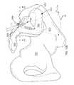
- external pelvic fixators 5are conventionally used to stabilize and rest a traumatized sacroiliac joint 3 until healed or asymptomatic (e.g., 6-12 weeks). External pelvic fixators 5 are conventionally recommended to diagnose and determine whether sacroiliac joint fusion would be a treatment option if the patient received pain relief from temporary stabilization of the sacroiliac joint 3 .
- the external pelvic fixators 5require multiple pins 2 placed in, e.g., the ilium 1 bilaterally (i.e., in both ilia) which is associated with significant risk and morbidity including but not limited to pain, infection and the inconvenience to the patient and medical person due to a bulky external frame around the pelvis.
- Another problem with conventional procedurescan be that there may be no or an insufficient reduction in the movements of a sacroiliac joint 3 .
- an insufficient reduction in the movements of a sacroiliac joint 3may be due to the extended distance from the fixation point provided by the external fixator relative to the sacroiliac joint 3 being evaluated.
- the complication rate for definitive and temporary conventional pelvic external fixationhas been reported to be rather significant.
- other conventional techniques for fixation of the joint 3may include placement of rods or screws 4 across a sacroiliac joint 3 within the ilium 1 and sacrum 0 defining the sacroiliac joint 3 .
- Yet further conventional techniques and implantsmay distract the joint and may thereby alter the tension of the surrounding ligamentous structure.
- Problems associated with these and other conventional techniques used primarily for sacroiliac joint fusionmay include the difficulty of removal of the implants, namely, because the implants and the associated conventional methods of use are generally intended for insertion only. That is, the implants, rods, and screws described with reference to the conventional art are not configured for temporary use or for diagnostic purposes.
- the rods shown in FIG. 1Cmay disrupt the interosseous ligament which the sacroiliac joint 3 depends on, in part, for stability in a healthy patient.
- other conventional implants and methodmay significantly disrupt the inner and outer table of the ilium, the cortical surface of the sacrum and may remove a significant volume of the bone of the sacrum and ilium.
- aspects of the present disclosureinvolve a method of diagnosing and treating a sacroiliac joint of a patient, the sacroiliac joint including a sacrum, an ilium, a joint line, an intra-articular region, and an extra-articular region.
- the methodincludes: a) delivering a first member into the ilium via a first posterior approach; b) delivering a second member into the sacrum via a second posterior approach; and c) diagnosing an ailment of the sacroiliac joint by manipulating the first member relative to the second member.
- manipulating the first member relative to the second membercomprises rotating the first member relative to the second member. In certain instances, rotation of the first member relative to the second member positions the sacroiliac joint in nutation. In certain instances, rotation of the first member relative to the second member positions the sacroiliac joint in counter-nutation. In certain instances, manipulating the first member relative to the second member comprises exerting a force on one of the first member or the second member in an anterior direction while exerting a stabilizing force on the other of the first member or the second member. In certain instances, manipulating the first member relative to the second member comprises exerting a force on one of the first member or the second member in a posterior direction while exerting a stabilizing force on the other of the first member or the second member.
- aspects of the present disclosurealso involve a surgical system for diagnosing and treating a sacroiliac joint of a patient, the sacroiliac joint having a sacrum and an ilium.
- the systemincludes a first member and a second member extending along a longitudinal axis, each of the members having a distal end that can be delivered into the sacrum and the ilium via a posterior approach; and a mechanical coupling assembly coupled between the first and second members, the coupling assembly configured to allow the first member to translate or rotate relative to the second member such that forces and directions of the forces applied by the first and second member to the sacrum and ilium can be manipulated to determine a treatment plan.
- each of the first and second membersincludes a bar or pin.
- the cross-section of the membershas a generally circular, square, rectangular or triangular shape.
- aspects of the present disclosurealso involve a surgical system for delivering an implant in a sacroiliac joint having a sacrum and an ilium.
- the systemincludes a first guide member extending along a first longitudinal axis, the first guide member having a distal end configured to be delivered into the sacrum via a posterior approach; a second guide member extending along a second longitudinal axis generally parallel to the first longitudinal axis, the second guide member having a distal end configured to be delivered into the ilium via the posterior approach; and a guide coupling member comprising a body having a proximal end, a distal end, and a first inner opening extending from the proximal end to the distal end, the body configured to slide on the first and second guide members and to receive an implant component from the proximal end of the guide coupling member and to deliver the implant component through the first inner opening from the distal end of the guide coupling member and into the sacroiliac joint along a predetermined trajectory.
- the systemfurther includes a spacer member positioned between the guide coupling member and the implant component, the spacer member having an outer surface configured to fit inside the first inner opening of the guide coupling member from the proximal end to the distal end and a second inner opening configured to fit to a size or shape of the implant component, such that the implant component can slide through the spacer member along the first and second guide members.
- aspects of the present disclosurealso involve a method for diagnosing and treating a sacroiliac joint of a patient, the sacroiliac joint having a sacrum and an ilium.
- the methodincludes placing a first guide member in the sacrum via a posterior approach; placing a second guide member in the ilium via the posterior approach; manipulating the first guide member and the second guide member to diagnose the sacroiliac joint by using a mechanical coupling assembly between the first and second guide members; removing the mechanical coupling assembly; aligning the first guide member with the second guide member to be generally parallel; sliding a guide coupling member to the first and second guide members; and delivering an implant component through the guide coupling member and into the sacroiliac joint.
- aspects of the present disclosurealso involve a method of diagnosing a medical condition associated with a sacroiliac joint of a patient.
- the methodincludes delivering a first member in close proximity to a sacroiliac joint region; and applying a force to the first member, the force including a periodic oscillation.
- FIG. 1Ais a superior view of a pelvic region and a conventional method and device for temporarily stabilizing the sacroiliac joint.
- FIG. 1Bis an anterior view of the pelvic region and the conventional method and device for temporarily stabilizing the sacroiliac joint of FIG. 1A .
- FIG. 1Cis an anterior view of the pelvic region and a conventional method and device for permanently stabilizing the sacroiliac joint.
- FIG. 2Ais an isometric view of an example system for fusing a sacroiliac joint.
- FIG. 2Bis the same view as FIG. 2A , except the delivery tool and implant assembly are decoupled from each other.
- FIG. 2Cis the same view as FIG. 2A , except the system is exploded to better illustrate its components.
- FIG. 3is a posterior-inferior view of a sacroiliac joint with a patient body shown in broken line.
- FIG. 4is a close-up view of the implant and anchor element in the sacroiliac joint.
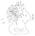
- FIG. 5Ais a right lateral view of a hip region of a patient lying in a prone position, wherein the soft tissue surrounding the skeletal structure of the patient is shown in dashed lines.
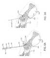
- FIG. 5Bis an enlarged view of the hip region of FIG. 5A .
- FIG. 5Cis generally the same view as FIG. 5B , except that the ilium is removed to show the sacroiliac joint space boundary defined along the sacrum and an implant positioned for implantation within the joint space.
- FIG. 5Dis a lateral side view of the pelvic region of a patient with a nearest ilium removed to clearly show the regions of the sacroiliac joint.
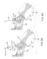
- FIG. 5Eis a lateral posterior view of the hip region of the patient showing the regions of the sacroiliac joint.
- FIG. 5Fis a posterior view of the hip region of the patient showing the regions of the sacroiliac joint.
- FIGS. 6A-6Dare each a step in the methodology and illustrated as the same transverse cross section taken along a plane extending generally medial-lateral and generally anterior posterior.
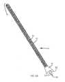
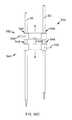
- FIG. 7Ais an isometric view of a diagnostic pin.
- FIG. 7Bis a bottom view of the diagnostic pin of FIG. 7A .
- FIG. 7Cis a top view of the diagnostic pin of FIG. 7A .
- FIG. 7Dis a side view of the diagnostic pin of FIG. 7A .
- FIG. 7Eis an isometric view of a diagnostic pin guidance tool.
- FIG. 8Ais an isometric view of a diagnostic pin with a blunt distal end.
- FIG. 8Bis an isometric view of a diagnostic pin with a blunt distal surface and a tapered tip extending distally of the blunt distal surface.
- FIG. 9is an isometric view of a diagnostic pin having a distal end with a pair of openings, the diagnostic pin coupled with an anchor guide.
- FIG. 10Ais a posterior view of a hip region of a patient showing a diagnostic pin positioned in the sacrum and another diagnostic pin positioned in the ilium.
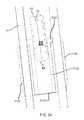
- FIG. 10Bis a lateral side view of the hip region of the patient with a nearest ilium removed and a diagnostic pin positioned in the sacroiliac joint region.
- FIG. 10Cis a posterior cross-sectional view of the sacroiliac joint with one pin positioned in the sacrum and one pin positioned in the ilium.
- FIGS. 10D-10Eare transverse cross-sectional views of the sacrum and ilium showing various pin placements in the sacrum.
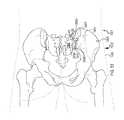
- FIG. 10Fis a posterior view of the hip region of the patient showing pins in a right ilium and a left ilium.
- FIG. 10Gis a posterior view of the hip region of the patient showing pins positioned in a right ilium and a left ilium for distracting the joint.
- FIG. 10His a posterior view of the hip region of the patient showing pins positioned in a right ilium and a left ilium for compressing the joint.
- FIG. 10Iis a posterior view of the lumbar spine showing pins to either stabilize or selectively allow motion between segments of the spine.
- FIG. 11is a lateral side view of the hip region of the patient in a neutral position with one pin in the sacrum and one pin in the ilium.
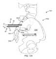
- FIG. 12Ais a lateral side view of the hip region of the patient showing anterior-posterior movement of the ilium via the pins positioned in the sacrum and ilium.
- FIG. 12Bis a lateral side view of the hip region of the patient showing cranial-caudal movement of the ilium via the pins positioned in the sacrum and ilium.
- FIGS. 12C-12Dare lateral side views of the hip region of the patient showing rotational movement of the ilium via the pins positioned in the sacrum and ilium.
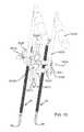
- FIG. 13Ais a lateral side view of the hip region of the patient showing possible pin placements in the ilium and sacrum.
- FIG. 13Bis a lateral side view of the hip region of the patient showing releasable distal portions of the pins being coupled with a coupling member.
- FIG. 14is a front isometric view of a diagnostic system including a mechanical coupling assembly coupled between a pair of diagnostic pins in accordance with embodiments of the present disclosure.
- FIG. 15is a back isometric view of the diagnostic system of FIG. 14 .
- FIG. 16A-16Care back views of the diagnostic system of FIG. 15 .
- FIG. 17is a top view of the diagnostic system of FIG. 14 .
- FIG. 18is an enlarged view of the mechanical coupling assembly of FIG. 14 .
- FIG. 19is an isometric view of the first coupling member of the diagnostic system of FIG. 14 .
- FIG. 20Ais one isometric view from the side of the second coupling member 5008 of the diagnostic system of FIG. 14 .
- FIG. 20Bis one isometric view from the bottom of the coupling member of the diagnostic system of FIG. 14 .
- FIG. 20Cis one isometric view from the top of the coupling member of the diagnostic system of FIG. 14 .
- FIG. 21is an isometric view of the fastener of the diagnostic system of FIG. 14 .
- FIG. 22is an isometric view of the washer of the diagnostic system of FIG. 14 .
- FIG. 23is an isometric view of the side screw of the diagnostic system of FIG. 14 .
- FIG. 24Ais an isometric view from the back of the third coupling member 5010 of the diagnostic system of FIG. 14 .
- FIG. 24Bis an isometric view from the front of the third coupling member 5010 of the diagnostic system of FIG. 14 .
- FIG. 25Ais an isometric view from the bottom of the connector at the end of the extension bar connected to the handle of the diagnostic system of FIG. 14 .
- FIG. 25Bis an isometric view from the top of the connector at the end of the extension bar connected to the handle of the diagnostic system of FIG. 14 .
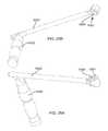
- FIG. 26is an isometric view of a diagnostic system including a pivot type mechanical coupling assembly for causing translational movements of the pins in accordance with embodiments of the present disclosure.
- FIG. 27is an isometric view of the diagnostic system of FIG. 26 in a position that one of the diagnostic pin moving upward in accordance with embodiments of the present disclosure.
- FIG. 28is an isometric view of the diagnostic system of FIG. 26 in a position that one of the diagnostic pin moving downward in accordance with embodiments of the present disclosure.
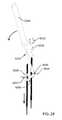
- FIG. 29is an isometric view of a diagnostic system including a pivot type mechanical coupling assembly for causing rotational movements of the pins in accordance with embodiments of the present disclosure.
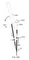
- FIG. 30Ais an isometric view of the diagnostic system that rotates one diagnostic pin clockwise with respect to another diagnostic pin.
- FIG. 30Bis an isometric view of the diagnostic system that rotates one diagnostic pin counterclockwise with respect to another diagnostic pin.
- FIG. 30Cis a front view of a diagnostic system that allows selective sliding of one pin relative to another pin.
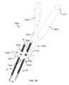
- FIG. 31is an isometric view from a bottom of a surgical system for delivering an implant in accordance with embodiments of the present disclosure.
- FIG. 32is an isometric view from a top of the surgical system for delivering an implant of FIG. 31 .
- FIG. 33is an isometric view of the surgical system of FIG. 31 with the implant inserted partially.
- FIG. 34is a sectional view of the surgical system of FIG. 33 with the implant inserted partially.
- FIG. 35is an enlarged sectional view illustrating that the implant is inserted in the extra-articular region.
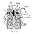
- FIG. 36is an enlarged sectional view illustrating that a cross type implant is inserted in the extra-articular region.
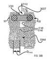
- FIG. 37is an enlarged sectional view illustrating that the fork-like shaped implant is inserted in the intra-articular region.
- FIG. 38is a sectional view of FIG. 37 as shown by arrows A-A.
- FIG. 39Ais an enlarged sectional view illustrating that one pin is inserted in ilium near extra-articular region and one pin is inserted into the sacrum near the intra-articular region with coupling between the pins.
- FIG. 39Bis an enlarged sectional view illustrating that one pin is inserted in ilium near extra-articular region and one pin is inserted into the sacrum near the extra-articular region with coupling between the pins.
- FIG. 39Cis an enlarged sectional view illustrating that one pin is inserted in ilium near intra-articular region and one pin is inserted into the sacrum near the intra-articular region with coupling between the pins.
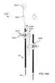
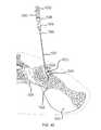
- FIG. 40is a simplified diagram illustrating an adjustable coupling member for the pins.
- FIG. 41is an enlarged sectional view illustrating that a temporary implant including coupled pins is inserted in the intra-articular region.
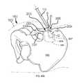
- FIG. 42illustrates a radiographic contrast tool that injects radiographic contrast under fluoroscopic guidance into the joint.
- FIG. 43Ais an isometric view from a distal end of an implant in accordance with a first embodiment of the present disclosure.
- FIG. 43Bis another isometric view from a proximal end of the implant of FIG. 43A .
- FIG. 44Ais an isometric view from a distal end of an implant in accordance with a second embodiment of the present disclosure.
- FIG. 44Bis another isometric view from a proximal end of the implant of FIG. 44A .
- FIG. 45Ais an isometric view from a distal end of an implant in accordance with a third embodiment of the present disclosure.
- FIG. 45Bis another isometric view from a proximal end of the implant of FIG. 45A .
- FIG. 46Ais an isometric view from a distal end of an implant in accordance with a fourth embodiment of the present disclosure.
- FIG. 46Bis another isometric view from a proximal end of the implant of FIG. 46A .
- FIG. 47Ais an isometric view from a distal end of an implant in accordance with a fifth embodiment of the present disclosure.
- FIG. 47Bis another isometric view from a proximal end of the implant of FIG. 47A .
- FIG. 48Ais an isometric view from a distal end of an implant in accordance with a sixth embodiment of the present disclosure.
- FIG. 48Bis another isometric view from a proximal end of the implant of FIG. 48A .
- FIG. 48Cis a side view of a curved implant in accordance with a seventh embodiment of the present disclosure.
- FIG. 48Dis an isometric view from a proximal end of the implant of FIG. 48C .
- FIG. 49Ais a lateral side view of the hip region of the patient with a nearest ilium removed and an implant positioned in the extra-articular region of the sacroiliac joint.
- FIG. 49Bis a lateral side view of the hip region of the patient showing an implant coupled with a delivery tool positioned for delivery into the sacroiliac joint.
- FIG. 49Cis the same view as FIG. 48B , except the implant has been delivered into the extra-articular region of the sacroiliac joint.
- FIG. 50is a lateral side view of the hip region of the patient showing positioning of the implant within the extra-articular region of the sacroiliac joint.
- FIG. 51is a posterior view of the hip region of the patient showing the implant within the extra-articular region of the sacroiliac joint.
- Implementations of the present disclosureinvolve a system for diagnosing and treating a sacroiliac joint disorder or ailment.
- the systemmay include a diagnostic tool for manipulating a pair of rods temporarily implanted or engaged with the hip region of the patient.
- a first rodmay engage with or be delivered into the sacrum and a second rod may be delivered parallel to the first rod and may engage with or be delivered into the ilium.
- the rodsmay span an intra-articular region or extra-articular region of the sacroiliac joint.
- the diagnostic toolmay be used to grasp and manipulate the rods such that the sacrum and ilium are manipulated relative to each other.
- the iliummay be, for example, translated proximally, distally, cranial, or caudal relative to the sacrum. Additionally, the ilium may be, for example, rotated in various planes relative to the sacrum via the diagnostic tool.
- the rodsmay be manipulated by hand without the aid of the diagnostic tool. The manipulation of the sacrum and ilium via the rods may be beneficial for a medical professional to diagnose a sacroiliac joint disorder because, for example, the rods may isolate the forces exerted to specific areas of the hip region (e.g., sacrum, ilium or lumbosacral spine). In certain instances, the diagnosis may indicate that stabilization of the joint is necessary.
- the jointmay be stabilized in a number of ways.
- the rodsmay be replaced by anchor or shorter rods and the rods may be coupled together, beneath the patient's skin. If a suitable amount of pain is reduced by this procedure, this may indicate that permanent fixation of the joint should alleviate or substantially reduce the pain.
- the rodsmay act as an alignment system for the subsequent delivery of a temporary implant. More particularly, a sleeve may be fitted over the rods and an insert may be fitted within the sleeve to guide a particular implant for delivery into the sacroiliac joint.
- the implantmay be delivered via a posterior approach into the sacroiliac joint and the implant may be delivered such that a portion of the implant bridges the joint and affixes into a portion of each of the sacrum and the ilium.
- the implantmay include an open distal end such that a majority of the body of the implant occupies the sacrum and the ilium with the open portion of the implant occupying the sacroiliac joint space so as to minimally disrupt the cartilage in the joint space.
- the temporary implantmay remain in the patient for a period of time to determine if a subsequent, permanent implant is needed. For example, if the temporary implant successfully treats the disorder, the implant may be removed in favor of implanting a permanent implant such as those described in U.S. patent application Ser. Nos. 14/447,612; 13/475,695; 13/236,411; and 12/998,712, all of which are incorporated by reference in their entireties into the present application. Accordingly, if a subsequent implant is to be delivered into the joint space, the joint may be prepared according to the systems, tools, and methods described in U.S. patent application Ser. No. 14/514,221, which is hereby incorporated by reference into the present application in its entirety. Or, the implant may remain implanted and a subsequent implant may or may not be delivered into the sacroiliac joint.
- a portion or entirety of a sacroiliac jointmay be treated, stabilized, or replaced by an implant, system and/or method as described in U.S. patent application Ser. No. 14/127,119, filed Dec. 17, 2013, entitled “Sacroiliac Joint Implant System” and incorporated herein by reference in its entirety.
- a fluid injection methodmay be used to inject pain medicine in the sacroiliac joint.
- itmay be difficult to accurately determine if the pain arises from the sacroiliac joint or other regions, because the fluid may leak to other nearby regions.
- the pain medicinemay leak in to other nearby regions and relieve the pain in those regions such that even if the pain is reduced, it is difficult to determine if the pain truly comes from the sacroiliac joint.
- the present diagnostic systemprovides a diagnostic system that can generate localized forces to cause movement of the sacroiliac joint.
- the diagnostic systemmay assist to accurately determine the need of an implant in the sacroiliac joint (or other treatment), either by stabilizing the joint to reduce the pain in a patient or by reproducing the pain in the patient via the localized forces to mobilize the joint or cause movement of the joint.
- This diagnostic system and methodmay provide accurate diagnostics on whether an implant is needed, thus, reducing the possibility of an unnecessary implant being implanted into the sacroiliac joint.
- the present disclosureprovides a diagnostic system that can be used to mobilize the sacroiliac joint of a patient in order to reproduce or stimulate pain in the patient.
- the patientmay provide feedback on whether the pain is similar to his or her familiar pain pattern. If the pain in the patient can be reproduced by manipulating the movement of the sacroiliac joint, this suggests that fusion, fixation, stabilization, or other treatment of the joint (e.g., with an implant) may be helpful to reduce the pain.
- Various methods and meansmay be used to mobilize the sacroiliac joint.
- the diagnostic systemmay include pins, rods, or bars that may be inserted or engaged with the sacrum or ilium at different locations to cause particular movements of the sacroiliac joint.
- the pins or barsmay have a distal end portion that can engage a larger region of the ilium or sacrum to cause the movement.
- the distal end portionmay extend from the pin in a radial direction such that the distal end portion may have a larger surface area.
- the distal end portionmay be a 2D or 3D plate.
- the diagnostic systemmay also include screws that are inserted in the ilium or sacrum.
- One shaftmay be used to couple to one screw while another shaft may be coupled to another screw.
- the shaftsmay be used to cause movements or stabilization of the joint.
- the distal portionmay be a hook.
- the distal portionmay be configured to reversibly expand (i.e., similar to a molly bolt or toggle bolt).
- the present disclosurealso provides a diagnostic system that can help determine if stabilizing the sacroiliac joint of a patient helps with reducing pain or other symptoms in the patient.
- the diagnostic systemmay include diagnostic pins coupled together that may be temporarily placed in the patient to stabilize the joint and to determine if the patient may have reduced pain. The pins may remain in the patient for a given period of time to determine if stabilization of the joint via the pins is effective at reducing pain. Instructions may be given to the patient to perform, e.g.: single leg stands, squats, sitting, rolling on side, movement of leg in various directions, an activity which causes accustomed symptoms. The patient may do certain work out routines on a running machine or cycling machine to provide feedback on whether the pain is reduced. The patient may also be instructed to live a regular daily life to provide feedback on whether the pain is reduced.
- the diagnostic systemmay also include delivering tools for implanting into the joint.
- FIG. 2Ais an isometric view of the system 10 .
- FIG. 2Bis the same view as FIG. 2A , except an implant assembly 14 of the system 10 is separated from a delivery tool 16 of the system 10 .
- FIG. 2Cis the same view as FIG. 2A , except the system 10 is shown exploded to better illustrate the components of the system 10 .
- the system 10includes a delivery tool 16 and an implant assembly 14 for implanting at the sacroiliac joint via the delivery tool 16 , the implant assembly 14 being for fusing the sacroiliac joint.
- the implant assembly 14includes an implant 12 and an anchor element 18 (e.g., a bone screw or other elongated body).
- an anchor element 18e.g., a bone screw or other elongated body.
- the implant 12 and anchor element 18are supported by a distal end 20 of the delivery tool 16 , as illustrated in FIG. 2A .
- the delivery tool 16is used to deliver the implant 12 into the sacroiliac joint space.
- the delivery tool 16is then used to cause the anchor element 18 to extend through the ilium, sacrum and implant 12 generally transverse to the sacroiliac joint and implant 12 .
- the delivery tool 16is then decoupled from the implanted implant assembly 14 , as can be understood from FIG. 2B .
- the delivery tool 16further includes a proximal end 22 opposite the distal end 20 , an arm assembly 24 , a handle 26 , an implant retainer 28 , a sleeve 30 and a trocar or guidewire 32 . While in the embodiment of FIGS.
- the delivery tool 16is fixed and non-adjustable and configured to deliver the anchoring element 18 in a single orientation relative to the implant 12
- the delivery tool 16may be adjustable and configured to deliver the anchoring elements 18 within a range of orientations relative to the implant 12 that will orient the anchoring element 18 either within a bore of the implant 12 , or adjacent implant 12 as described in U.S. patent application Ser. No. 14/447,612, filed Jul. 31, 2014, entitled SYSTEMS FOR AND METHODS OF FUSING A SACROILIAC JOINT, which is hereby incorporated by reference in its entirety.
- first and second articular faces of the implant 12may be selected to match the contour of the joint space of the sacroiliac joint within which the implant 12 is to be inserted.
- the sacral, medial or first articular faces of the implantmay be configured to be generally convex to match the contour of a sacral auricular boney surface or to match the contour of an extra-articular region of a sacrum (e.g., a sacral fossa).
- a sacral auricular boney surfacee.g., a sacral fossa.
- the sacral, medial or first articular face of the implant 12may be generally a surface negative of the articular surfaces 1016 of the extra-articular region 3007 and/or articular region 1044 of the sacrum 1004 .
- the lateral, iliac or second articular face of the implant 12may be configured to be generally concave to match the contour of an iliac auricular boney surface or to match the contour of an extra-articular region of an ilium (e.g., an iliac tuberosity).
- the lateral, iliac or second articular face of the implant 12may be generally a surface negative of the articular surfaces 1016 of the extra-articular region 3007 and/or articular region 1044 of the ilium 1005 .
- FIGS. 2A-2Cmay be used in a surgical procedure via a posterior approach, as seen in FIGS. 3-4 .
- FIG. 3which is a posterior-inferior view of a sacroiliac joint 36 with a patient 40 shown in broken line
- the delivery tool 16is positioned to deliver the implant 12 into a caudal region 34 of the sacroiliac joint 36 and the anchoring element 18 through the ilium 5 and into the bore 38 of the implant 12 .
- the implant 12 and anchoring element 18have been inserted into the caudal region 34 of the sacroiliac joint 36 and the delivery tool 16 has been removed.
- a system as described hereinmay be used in a surgical procedure via an anterior approach (e.g., such that the surgical pathway includes traversing an anterior boundary segment 3004 and/or traversing an anterior-inferior corner 3010 ) and may further include positioning an implant into a sacroiliac joint such that: 1) the implant longitudinal axis a) is generally parallel to a sacroiliac joint inferior boundary segment 3002 , or b) points towards a posterior superior iliac spine, or c) point towards a posterior inferior iliac spine, or d) points toward a sacroiliac extra-articular region; or, 2) the distal end of the implant generally lies within a) a caudal region of the sacroiliac joint articular region, or b) an extra-articular portion of the sacroiliac joint, or c) a cranial portion or cephalad region of the sacroiliac joint
- a system as described hereinmay be used in a surgical procedure via an approach which includes a surgical pathway which transverses a sacroiliac joint inferior boundary segment 3002 , e.g., as described in U.S. patent application Ser. No. 13/945,053, filed Jul. 18, 2013, entitled SYSTEMS AND METHODS OF FUSING A SACROILIAC JOINT, which is hereby incorporated by reference in its entirety.
- a surgical procedure via this pathwaymay further include positioning an implant into a sacroiliac joint such that: 1) the implant longitudinal axis a) is transverse to a sacroiliac joint inferior boundary segment 3002 , or b) points towards a posterior superior iliac spine, or c) point towards a posterior inferior iliac spine, or d) points toward a sacroiliac extra-articular region, or e) points towards a sacroiliac joint anterior boundary segment 3004 , or f) points towards either superior boundary segment corner 3014 or 3012 or somewhere in-between; or, 2) the distal end of the implant generally lies within a) a caudal region of the sacroiliac joint articular region, or b) an extra-articular portion of the sacroiliac joint, or c) a cranial portion or cephlad region of the sacroiliac joint articular region.
- an implant 12may be inserted along a generally arcuate path. Accordingly, a surgical preparation technique and tools may be utilized while operating in an arcuate path.
- the implant arcuate pathmay follow and generally match the surgical preparation arcuate path and the path arc may include a radius of between approximately 3 cm to 6 cm.
- the portion of the path having an arcuate path including a radius of between approximately 3 cm to 6 cmmay reside substantially in the plane of the sacroiliac joint or in a plane in close proximity and generally parallel thereto.
- the arcuate pathmay generally or substantially reside in sacroiliac joint articular region 1044 .
- an implantmay be selected for use during the procedure which substantially matches the radius or curvature of the arcuate or curved insertion path or surgical preparation path.
- a sleevemay guide (alone or along with another cannulated tool, e.g., a needle) a bone paste, bone marrow aspirate, stem cells, allograft or any biocompatible material or substance into the sacroiliac joint space via a path with a trajectory which may be generally transverse to the plane of the sacroiliac joint.
- the sleevemay be caused to form a seal with a bone defining the sacroiliac joint, e.g. the ilium.
- the sealmay be created by impacting a proximal end of sleeve which may, for example, cause the sleeve to slightly penetrate the cortex of the outer table of the ilium.
- a cannulated toolsuch as a large gauge needle or tube may either be interference fit within a hole in the ilium or the needle or tube may have a threaded distal end which may be threaded into the bore formed in the ilium.
- a plunger or bone tampmay be forced through a sleeve to advance the bone paste or other material into the sacroiliac joint space, adjacent/around the implant and/or into the bone graft window of the implant.
- an anchorsuch as a bone screw may be advanced via the sleeve into engagement with an opening formed in the ilium and driven across the sacroiliac joint and further into the sacrum.
- a bone plugmay be positioned into the opening formed in the ilium in order to occlude the passageway between the outer cortex of the ilium and the implanted bone paste or other material positioned generally in the plane of the joint.
- a surgeon or other medical personmay diagnose a particular ailment of the sacroiliac joint and select a suitable procedure to treat the sacroiliac joint, e.g., fusion, fixation, stabilization, replacement, resurfacing, restructuring, repairing, or altering of boney ligamentous or capsular tissue.
- the proceduremay include fusing the joint with or without delivering an implant in the joint space.
- a diagnostic and/or treatment proceduremay be planned and/or conducted (and, e.g., the surgeon may select an implant configuration for delivery into the sacroiliac joint region of the patient) based on preoperative or intraoperative data.
- the datamay be the result of post-processing of raw or other imaging data (e.g.
- the post-processingmay include the use of a software program (e.g., 3DSLICER available from http://www.slicer.org) that may be used for medical image processing and 3D visualization of image data.
- Other datamay include the patient's weight, activity level, spinal alignment, posture and general health.
- the preoperative or intraoperative datamay assist in the planning and selecting of desirable implant and final anchor positioning, trajectories (e.g., starting and stopping points on patient's soft tissue and near or within bone tissue), anchor, number, configurations and dimensions (e.g., length, cannulation, apertures, cross sectional geometry, surface treatments, diameter, head size, washer, thread pitch), implant types, number, configurations and dimensions, and joint preparation tool types, dimensions, and configurations.
- a particularly system for preparing and fusing the sacroiliac jointmay be selected, for example, for a hypermobile joint, which may include an implant or fusion system that is resistant to the expected forces (magnitude and vector) present at that particular patient's sacroiliac joint.
- fixation sufficiencymay be calculated based on the patient's data and also on the performance results of various bench and/or finite element analysis (“FEA”) tested implant assembly (or individual components) configurations. For example, a calculated anchor and/or implant trajectory may be considered and determined from certain patient imaging and post-processing data with an overlayed implant assembly. Further, the implant assembly footprint within the joint plane may be selected as a lower percent of total joint surface area to permit sufficient boney fusion across the joint while maintaining a sufficient implant sacral and iliac face surface area to prevent implant subsidence.
- FFAfinite element analysis
- the patient's bone densitymay be measured at numerous locations in proximity to and surrounding the elements of the implant assembly.
- Lower bone densitye.g., osteopenia, osteoporosis
- a T-score lower than ⁇ 1sacroiliac joint instability, or hypermobility
- an implant assembly with a greater amount of keel (or a particular keel configuration)i.e., the material cross section as defined by thickness of the keel and its length along implant longitudinal axis and also keels extending a greater distance into both bones defining the sacroiliac joint
- anchorextending across the sacroiliac joint and into the ilium and sacrum.
- the relative angles between the implant longitudinal axis and anchor or anchors, and also the relative angles between multiple anchorsmay be preselected based on the patient
- a comparison of the preoperative or intraoperative datae.g., sacroiliac joint surface area, joint mobility, loading, bone density, desirable anatomic pathways
- the selected implant assembly and joint preparation toolsmay be conducted to ensure or validate compatibility before the manufacture ships the implant system and/or before the surgeon employs the system in a surgical procedure.
- implant assembly and preparation tools validationthe selected assemblies may be shipped to the surgeon and the surgeon may proceed with the surgical fusion procedure utilizing the selected assemblies.
- various aspects of the diagnostic toolsmay be selected based on the same or similar data and/or studies. Additionally, placement of the various components of the diagnostic systems in to the sacroiliac joint region and/or the amount of displacement of one bone relative to another may be chosen or guided by one or more of the following: the anchor trajectory and placement may be guided and confirmed with imaging studies before the end of the surgical procedure or afterwards.
- a surgeonmay use fluoroscopy (and/or arteriography) to obtain an anteroposterior view, lateral view, an inlet view, an outlet-oblique view, Judet views of the pelvis, an internal (obturator) oblique view, a Ferguson view, an external (iliac) oblique view or other relevant views and further use radiographic boney landmarks such as the superimposed greater sciatic notches, superimposed iliac cortical densities or alar slope, sacral promontory, first sacral endplate, sacral foramina, arcuate sacral lines, iliopectineal line, ilioishial line, acetabular teardrop lines bony corridors of S1 or S2, superimposed acetabula, ventral and dorsal surfaces of the sacrum, etc.; or using an angiogram to identify vascular structures such as the superior gluteal artery, internal iliac artery and vein, iliolumbar vein, etc.
- FIGS. 5A-5Bdepict various bone landmarks adjacent, and defining, the sacroiliac joint 1000 of a patient 1001 .
- FIG. 5Ais a right lateral view of a hip region 1002 of a patient 1001 lying prone, wherein the soft tissue 1003 surrounding the skeletal structure 1006 of the patient 1001 is shown in dashed lines. Delivery of an implant into the sacroiliac joint 1000 and, thus, preparing of the joint 1000 for delivery of the implant may be conducted via a posterior approach to the hip region 1002 .
- FIG. 5Bwhich is an enlarged view of the hip region 1002 of FIG.
- FIG. 5Adepicts a lateral view of the patient's hip region 1002 and reveals certain features of the ilium 1005 , including the anterior superior iliac spine 2000 , the iliac crest 2002 , the posterior superior iliac spine 2004 , the posterior inferior iliac spine 2006 , the greater sciatic notch 2008 extending from the posterior inferior iliac spine 2006 to the ischial spine 2010 , and the tubercle of the iliac crest 2012 .
- the sacroiliac joint articular region or intra-articular region 1044is shown in dashed lines.
- the articular region 1044is a portion of the sacroiliac joint 1000 formed between articular surfaces of the ilium 1005 and sacrum 1004 .
- the articular region 1044is typically covered in a thin plate of cartilage and is surrounded by a fibrous capsule containing synovial fluid.
- Boundaries of the sacroiliac joint articular region 1044are as follows.
- a posterior inferior access region 2016 of the sacroiliac joint articular region 1044has a superior end 2018 on the sacroiliac joint line 2019 that is between approximately 0 mm and approximately 40 mm inferior the posterior inferior overhang 2020 of the posterior superior iliac spine 2004 .
- the posterior inferior access region 2016 of the sacroiliac joint articular region 1044has an inferior end 2022 on the sacroiliac joint line that is at approximately the intersection of the posterior inferior iliac spine 2006 with the lateral anterior curved boundary 2024 of the sacrum 1004 .
- the posterior inferior access region 2016 of the sacroiliac joint articular region 1044has an inferior end 2022 on the sacroiliac joint line that is at approximately the superior beginning of the greater sciatic notch 2008 .
- the sacroiliac joint articular region 1044roughly defines an L-shape or boot-shape that includes a caudal region 1086 and a cranial region 1087 .
- Access into the caudal region 1086 of the sacroiliac jointmay be accomplished via the posterior inferior access region 2016 that extends between corners defined by the superior end 2018 and the inferior end 2022 .
- Access into the cranial region 1087may be accomplished by continual, anterior travel in the caudal region 1086 until the articular region 1044 turns superiorly into the cranial region 1087 .
- FIG. 5Cis a close-up lateral side view of the hip region 1002 of a patient 1001 with a nearest ilium 1005 removed in order to show the sacroiliac joint boundary 3000 defined along the sacrum 1004 and outlining the sacroiliac joint articular region 1044 , and an implant 25 positioned for implantation within the sacroiliac joint articular region 1044 .
- boundaries along the sacroiliac joint articular region 1044include an inferior boundary segment 3002 , an anterior boundary segment 3004 , a superior boundary segment 3006 , and a posterior boundary segment 3008 .
- the inferior boundary segment 3002is immediately adjacent, and extends along, the sciatic notch 2024 .
- the inferior boundary segment 3002 and anterior boundary segment 3004intersect to form an anterior-inferior corner 3010 .
- the anterior boundary segment 3004 and superior boundary segment 3006intersect to form an anterior-superior corner 3012 .
- the superior boundary segment 3006 and posterior boundary segment 3008intersect to form a superior-posterior corner 3014 .
- the posterior boundary segment 3008 and posterior inferior access region 2016intersect to form a superior-posterior corner 3016 of the posterior inferior access region 2016 .
- the inferior boundary segment 3002 and posterior inferior access region 2016intersect to form an inferior-posterior corner 3018 of the posterior inferior access region 2016 .
- the inferior boundary segment 3002extends between corners 3010 and 3018 .
- the anterior boundary segment 3004extends between corners 3010 and 3012 .
- the superior boundary segment 3006extends between corners 3012 and 3014 and provides an access into the cranial portion 1087 of the sacroiliac joint.
- the posterior boundary segment 3008extends between corners 3014 and 3016 .
- the posterior inferior access region 2016extends between corners 3016 and 3018 and provides an access into the caudal region 1086 of the sacroiliac joint.
- the posterior boundary segment 3008separates the articular region 1044 and the extra-articular region 3007 , which includes the sacral fossa on the sacrum 1004 and the corresponding iliac tuberosity on the ilium 1005 and defined by the extra-articular region boundary 3009 .
- the implant 25may be delivered via an implant arm 111 of a delivery tool into the caudal region 1086 of the sacroiliac joint articular region 1044 .
- the implant 25enters the posterior inferior access region 2016 , and is further advanced into the caudal region 1086 of the sacroiliac joint articular region 1044 , in an orientation such that the implant arm 111 and wide planar members 51 are in the joint plane and the longitudinally extending edge 3050 of the wide planar member 51 next to the inferior boundary segment 3002 is generally parallel to, and immediately adjacent to, the inferior boundary segment 3002 .
- the distal end 43 of the implantis heading generally perpendicular to, and towards, the anterior boundary segment 3004 .
- the implant 25enters the posterior inferior access region 2016 , and is further advanced into the caudal region 1086 of the sacroiliac joint articular region 1044 , in an orientation such that the implant arm 111 and wide planar members 51 are in the joint plane and the longitudinally extending edge 3050 of the wide planar member 51 next to the inferior boundary segment 3002 is somewhere between being generally parallel to the inferior boundary segment 3002 (as illustrated by the solid-lined implant 25 in FIG. 5C ) or forming an angle AJ with the inferior boundary segment 3002 of up to approximately 50 degrees.
- the distal end 43 of the implant shown in dashed linescan be said to head anywhere from generally perpendicular to, and towards, the anterior boundary segment 3004 to heading generally towards the superior-anterior corner 3012 , or points in between.
- the implant 25may be first directed into the joint space as illustrated by the solid-lined implant 25 in FIG. 5C after which the implant 25 is rotated within the joint space to be positioned somewhere between, and including, angled position depicted by the dashed-lined implant 25 .
- the implant 25may be first directed into the joint space as illustrated by the dashed-lined implant 25 in FIG. 5C after which the implant 25 is rotated within the joint space to be positioned somewhere between, and including, the parallel position depicted by the solid-lined implant 25 .
- an implant 25may be delivered non-transversely (i.e., within the joint and not across the joint) into the caudal region 1086 , the cranial portion 1087 , or partially within each of the caudal and cranial regions 1086 , 1087 of the sacroiliac joint articular region 1044 . Further details of the implant delivery can be found in related applications, mentioned previously, such as U.S. patent application Ser. No. 12/998,712, which is incorporated by reference herein in its entirety.
- FIG. 5Ddepicts a close-up lateral view of the hip region 1002 of FIG. 5C , except the implant is not shown.
- FIG. 5Dshows additional anatomical features of the extra-articular region 3007 of the joint.
- the extra-articular region boundary 3009has a caudal boundary segment 3093 , an anterior boundary segment 3094 , and a posterior boundary segment 3097 .
- the caudal boundary segment 3093 and the anterior boundary segment 3094separate the intra-articular region 1044 and the extra-articular region 3007 .
- the posterior boundary segment 3097is immediately adjacent and extends along the sacroiliac joint line 2019 .
- the caudal and anterior boundary segments 3093 , 3094intersect to form an anterior-inferior corner 3095 .
- the caudal boundary segment 3093intersects with the posterior boundary segment 3097 to form a posterior-inferior corner 3091 .
- the anterior boundary segment 3094 of the extra-articular boundary 3009intersects with the posterior boundary segment 3097 for form a posterior-anterior corner 3096 .
- the sacroiliac extra-articular region 3007has an extra-articular recess access region 6000 , which spans the posterior boundary segment 3097 and has an inferior end 3092 (i.e., generally coincident with posterior inferior corner 3091 ) and a superior end 3098 located near the posterior anterior corner 3096 along the sacroiliac joint line 2019 .
- the extra-articular access region 6000has an extra-articular posterior-inferior access region 6001 that has an inferior end 3092 along the sacroiliac joint line 2019 .
- the inferior end 3092is generally coincident with the posterior inferior corner 3091 .
- the inferior end 3092is immediately adjacent both the superior-posterior corner 3016 and the superior end 2018 of the posterior inferior access region 2016 .
- FIGS. 5E-5Fdepict, respectively, a lateral-posterior view and a posterior view of the hip region 1002 of the patient 1001 .
- These figuresinclude many of the anatomical features referred to in FIGS. 5B-5C and the some of the additional anatomical features described in FIG. 5D .
- the articular region 1044 and extra-articular region 3007are shown in dashed line with many of their respective boundaries identified in each figure.
- FIG. 5Edepicts the posterior inferior access region 3090 of the sacroiliac joint extra-articular region 3007 and inferior end 3092 of the extra-articular posterior inferior access on the sacroiliac joint line 2019 .
- the posterior inferior access region 2016 of the intra-articular region 1044has the superior end 2018 on the sacroiliac joint line 2019 that is immediately adjacent the inferior end 3092 of the caudal boundary segment 3093 of the extra-articular region 3007 .
- FIGS. 6A-6Dare steps in the methodology and illustrated in the same transverse cross section taken in along a plane extending medial-lateral and anterior posterior.
- articular surfaces 1016are covered by a thick layer of articular cartilage with a joint space existing between them, the FIGS. 6A-6D are simplified for illustrative purposes and do not show these features to scale.
- an embodiment of the methodcan include the step of placing a patient under sedation prone on a translucent operating table (or other suitable surface).
- the sacroiliac joint 1000can be locally anesthetized to allow for injecting a radiographic contrast 1046 (as a non-limiting example, Isoview 300 radiographic contrast) under fluoroscopic guidance into the inferior aspect of the sacroiliac joint 1000 to outline the articular surfaces 1016 of the sacroiliac joint 1000 ) defined between the sacrum 1004 and ilium 1005 , the sacroiliac joint 1000 having an interarticular region 1044 .
- a radiographic contrast 1046as a non-limiting example, Isoview 300 radiographic contrast
- Injection of the radiographic contrast 1046 within the sacroiliac joint 1000can be accomplished utilizing a tubular member 1047 (e.g., a syringe needle) having first tubular member end 1048 which can be advanced between the articulating surfaces 1016 of the sacroiliac joint 1000 and having a second tubular member end 1049 which removably couples to a hub 1050 .
- the hub 1050can be configured to removably couple to a syringe barrel 1051 or other device to contain and deliver an amount of radiographic contrast 1046 .
- the syringe barrel 1051can have an internal volume capable of receiving an amount of the radiographic contrast 1046 sufficient for outlining the articular surfaces 1016 of the sacroiliac joint 1000 , for example, under lateral fluoroscopy.
- a plunger 1052can be slidingly received within the barrel 1051 to deliver the radiographic contrast 1046 through the tubular member 1047 into the sacroiliac joint 1000 .
- the tubular member 1047can have a gauge in the range of about 16 gauge and about 20 gauge and can further be incrementally marked on the external surface to allow determination of the depth at which the first needle end 1048 has advanced within the sacroiliac joint 1000 .
- the radiographic dye 1046can be delivered from within the syringe barrel 1051 into the sacroiliac joint 1000 to allow visualization of the sacroiliac joint 1000 and location of the tubular needle 1047 within the sacroiliac joint 1000 .
- the hub 1050can be removed from the tubular member 1047 leaving the tubular member 1047 fixed within the sacroiliac joint 1000 as an initial guide for tools subsequently used to locate or place the sacroiliac joint implant non-transversely between the articulating surfaces 1016 of the sacroiliac joint 1000 (e.g., locate the implant non-transversely to the joint plane 1030 generally defined by the articulating surfaces 1016 of the interarticular region 1044 of the sacroiliac joint 1000 ) or in removal of a portion of the sacroiliac joint 1000 within the region defined by the articular surfaces 1016 to generate an implant receiving space 1029 .
- one or more guide pins 1013can be inserted along substantially the same path of the tubular member 1047 for
- a small incision 1053can be made in the skin at the posterior superior, or as to certain embodiments inferior, aspect of the sacroiliac joint 1000 , extending proximal and distal to the tubular member 1047 along the line of the sacroiliac joint 1000 to provide a passage to access the interarticular space between the articulating surfaces 1016 (see FIG. 6B ) of the sacroiliac joint 1000 . More specifically, the small incision 1053 can be made along the joint line of the sacroiliac joint 1000 in the tissue covering the posterior inferior access region 2016 of the sacroiliac joint articular region 1044 .
- a cannulated probe 1054can be slidingly engaged with the tubular member 1047 (or guide pin 1013 ) extending outwardly from the sacroiliac joint 1000 (while the sacroiliac joint may be shown in the figures as being substantially linear for illustrative purposes, it is to be understood that the normal irregular features of the sacroiliac joint have not been removed).
- the cannulated probe 1054can have a probe body 1054 of generally cylindrical shape terminating in a spatulate tip 1055 at the end advanced into the sacroiliac joint 1000 .
- a removable cannulated probe handle 1056couples to the opposed end of the probe body 1054 .
- the spatulate tip 1055can be guided along the tubular needle 1047 or guide wire 1013 into the posterior portion of the sacroiliac joint 1000 and advanced to the anterior portion of the sacroiliac joint 1000 under lateral fluoroscopic visualization.
- the cannulated probe handle 1056can then be removed providing the generally cylindrical probe body 1054 extending outwardly from the sacroiliac joint 1000 through the incision 1053 made in the skin.
- the probe 1054can be used to guide, advance or place a needle, guide wire or other instrument up to, near, or into the joint.
- probe handle 1056 or the opposed end of the probe body 1054can be configured to have an interference fit or a luer lock hub to communicate with a syringe barrel 1051 in order to advance contrast, in situ curable biocompatible materials, stem cells, or etc. through the cannulated probe 1054 or cannulated probe handle 1056 .
- a passage from the incision 1053 (see FIG. 6C ) to the sacroiliac joint 1000can be generated by inserting a cannula 1057 into the incision.
- a soft tissue dilator 1058 having a blunt end 1059can be advanced over the probe body 1054 , or a plurality of soft tissue dilators of increasing size, until the blunt end 1059 of the soft tissue dilator 1058 and the corresponding cannula end contact the posterior aspect of the sacroiliac joint 1000 .
- the ends of the dilator 1058 and cannula 1057contact the joint line 2019 of the sacroiliac joint 1000 at the posterior inferior access region 2016 of the sacroiliac joint articular region 1044 .
- the soft tissue dilator 1058can be removed from within the cannula 1057 .
- the external surface of the cannula 1057can be sufficiently engaged with the surrounding tissue to avoid having the tissue locate within the hollow inside of the cannula 1057 .
- a non-limiting embodiment of the cannula 1057provides a tubular body having substantially parallel opposed side walls which terminate in a radius at both ends (lozenge shape) into which a plurality of different jigs can be inserted.
- cannula 1057 and corresponding dilators 1058 and alignment jigs 1060can be configured to have tubular bodies with an elliptical or circular cross section.
- the cannula 1057may be additionally configured to have within or near its walls a light source such as, for example, a fiberoptic or a LED light source to assist in visualization of the working area. Also, in some embodiments, irrigation and suction tubing may communicate with the inside passage of cannula 1057 .
- an amount of articular cartilage or other tissues from between the articular surfaces of the sacroiliac joint 1000can be removed sufficient to allow embodiments of the sacroiliac joint implant to be implanted in replacement of the removed articular cartilage or tissue. Because the method removes the degenerative articular cartilage or tissue between the articular surfaces of the sacroiliac joint 1000 , the articular surfaces of the sacroiliac joint 1000 can remain intact or substantially intact allowing the sacroiliac joint implant to be non-transversely located between the articular surfaces of the sacroiliac joint 1000 .
- articular cartilage or tissue between articular surfacessuch as any of the tools previously described or any of: endoscopy tools, box chisels, side cutting router bits, burs, flexible burs and bits, hole saws, key hole saw, medical bone chainsaw osteotome, curettes, lasers (e.g., C02, Neodymium/Y AG (yttrium-aluminum-garnet), argon, and ruby), electrosurgical equipment employing electromagnetic energy (the cutting electrode can be a fine micro-needle, a lancet, a knife, a wire or band loop, a snare, an energized scalpel, or the like) where the energy transmitted can be either monopolar or bipolar and operate with high frequency currents, for example, in the range of about 300 kHz and about 1000 kHz whether as pure sinusoidal current waveform where the “crest factor” can
- Electrosurgical waveformsmay be set to promote two types of tissue effects, namely coagulation (temperature rises within cells, which then dehydrate and shrink) or cut (heating of cellular water occurs so rapidly that cells burst).
- the proportion of cells coagulated to those cutcan be varied, resulting in a “blended” or “mixed” effect.
- a fully rectified current, or a partially rectified current, or a fulguration current where a greater amount or lateral heat is producedcan be employed to find the articular surfaces of the joint and aid in advancing a probe or guide wire into a position in between the articulating surfaces. These currents can effectively degrade the cartilage and allow advance into the joint without grossly penetrating much beyond the cartilage.
- the following discussionwill focus on various tools, systems, and methods of diagnosing and treating a sacroiliac joint ailment or disorder.
- the tools, systems, and methodsmay be useful in determining if fusion of the sacroiliac joint may be beneficial to a patient by, for example, alleviating pain.
- the tools and systemsmay be used to isolate the bones in the pelvic region such that manipulation of the bones (e.g., sacrum, ilium) can more easily, accurately, and efficiently diagnose the sacroiliac joint as a source of pain and discomfort.
- the jointmay be temporarily or permanently fixated.
- the following discussionwill focus on the tools, systems and methods of diagnosing and treating a sacroiliac joint disorder or ailment.
- FIGS. 7A-7Fillustrate diagnostic pins, rods, or bars 50 for use in diagnosing an ailment of a sacroiliac joint of a patient.
- the diagnostic pins 50may be manipulated to cause movement of the sacrum and/or ilium, which may reproduce the pain in the patient or alleviate the pain in the patient (e.g., may realign the sacroiliac joint). In either scenario and depending on the particular manipulation, reproducing or alleviating the pain may suggest a need for fusing the joint via, for example, an implant.
- the diagnosticsmay suggest that the pain may come from areas other than the sacroiliac joint, such that fusion of the sacroiliac joint may not help to reduce the patient's pain. For these reasons, among others, the diagnostic method described herein may eliminate unnecessary implantation and trauma to the sacroiliac joint.
- the diagnostic pins 50may be caused to rotate or translate, which may cause movement of the sacrum and ilium about the joint.
- one pin 50may be placed in the sacrum while the other pin 50 may be placed in the ilium.
- the movement of the sacrum and iliummay vary depending upon the locations of the diagnostic pins or bars 50 and direction of the force. If the pin 50 is positioned on (or in) the caudal region of the sacrum and pushed anteriorly, the cephalad portion sacrum may rotate toward the posterior direction. If the pin is placed near the first sacral body (i.e., a cephalad portion of the sacrum) and a force is directed anteriorly, the cephalad portion of the sacrum may rotate toward the posterior direction.
- One pinmay be placed in the ilium near the intra-articular region or extra-articular region of the joint.
- the pin 50may include an elongated body 52 extending between a distal end 54 and a proximal end 56 .
- the distal end 54may be tapered and include threads 60 that terminate at a point 58 such that the pin 50 may be rotationally driven into the bone.
- the threads 60may be self-tapping threads.
- the distal end 54may have a smaller cross-section than the proximal end 56 . It will be appreciated by those skilled in the art that the cross-section of pins or bars 50 may be generally circular, oval, square, rectangular or triangular in shape.
- the elongated body 52includes longitudinally extending and radially projecting ridges 62 that extend from the proximal end 56 to the threads 60 near the distal end 54 of the pins 50 .
- the ridges 60provide grip for the pins 50 when grasped by a medical professional or a mechanical device.
- the pinsmay be configured with a high-friction surface.
- the elongate body 52may have a diameter of in the range of about 3 millimeters (“mm”) to about 8 mm (e.g., 6 mm) and a length disposed between the proximal and distal ends 56 , 54 in the range of about 2 centimeters (“cm”) and about 20 cm. Pin length measurements may be marked along the length of the pin 50 .
- the pin 50 proximal end 56may have a tool interface configured to permit, e.g., a handle or other tool to couple to the elongate body 52 .
- the elongate body 52can further include a cannulation which communicates between the distal end 54 and the proximal end 56 .
- the cannulationallows for placement within the cannulation a guide pin (or other guide member) about which embodiments of the pins 50 can be guided for insertion and placement in the bones of the sacrum 1004 or ilium 1005 , or allow injection of analgesics.
- FIG. 7Eis an isometric view of a pin guidance tool 520 for guiding the placement of the pins 50 within the sacrum and ilium, respectively.
- the tool 520includes a guidance head 522 with three cylindrical openings 524 on a left side 526 of the head 522 and three cylindrical openings 524 on a right side 528 of the head 522 .
- the tool 520further includes a handle 530 coupled and extending from the guidance head 522 .
- the tool 520is configured to guide one or more pins 50 within the openings 524 into the sacrum or ilium. When used to guide multiple pins 50 , the pins will be delivered parallel to each other and with a pre-determined amount of space or distance between the placements.
- a first pinmay be guided along trajectory TR 1 into the sacrum and a second pin may be guided along another trajectory TR 2 into the ilium.
- the doctor or medical professionalcan be assured that the pins are parallel to each other and spaced apart a certain, known, distance. While this example and the figure shows the trajectories TR 1 , TR 2 utilizing the most inner openings 524 , the tool 520 may be used with other combinations of openings 524 without limitation.
- the pin 50may include a similar proximal end 56 and elongated body 52 with ridges 62 that was previously described in reference to FIGS. 7A-7D .
- the pin 50 of FIG. 8Amay, however, include a blunt distal end 64 instead of a threaded 60 distal end 54 that terminates at a point 58 .
- the blunt distal end 64may include, for example, a planar distal surface 66 that may conform to the surface features of the bone or may simply be configured to not penetrate or minimally penetrate into the boney surfaces of the sacrum or ilium upon contact.
- the planar distal surface 66may include surface features such as ridges or points that are configured to grip the bone surfaces upon contact.
- the planar distal surface 66may include a threaded distal end 54 that extends through the planar distal surface 66 and distally terminates at a point 58 .
- Other variations to the pin 50are contemplated herein and may include any type and kind of blunt distal end that is not designed to extend into the patient's bone upon application of a force.
- the distal end 64may include surface contours that match the bones of the ilium and sacrum so as to provide a mating surface with which to apply force against.
- the medical professionalmay position the pin 50 in various orientations and on various boney landmarks to manipulate the sacrum and ilium without boring multiple holes into the patient's bone.
- the medical professionalcan attempt multiple different kinds and styles of manipulation prior to or instead of boring holes into the patient's bone.
- the pin 50includes a planar, plate member 64 at the distal end 54 with a pair of openings 66 extending transversely or across the plate member 64 .
- the pin 50may be used in conjunction with an anchor guide 68 that may guide anchors 70 , such as bone screws, into the openings 66 of the plate member 64 when a sleeve 72 of the anchor guide 68 extends over the elongated body 52 of the pin 50 .
- the anchor guide 68may further include an extension member 74 extending from the sleeve 72 to a pair of guides 76 that are configured to align a trajectory TJ of the anchors 70 across the plate member 64 and into the openings 66 when the sleeve 72 is positioned on the elongated body 52 .
- a shaft of a delivery tool(not shown) may be guided by the guides 76 to deliver the anchors 70 into the openings 66 .
- the pin 50 and anchor guide 68 shown in FIG. 9may be delivered into a patient's pelvic region and positioned such that the plate member 64 lies generally parallel with a posterior lateral surface of the ilium, for example.
- the openings 66 of the plate member 64may be oriented on the ilium such that a trajectory of the anchors 70 is across either the intra-articular region or the extra-articular region of the sacroiliac joint and into the sacrum.
- the anchors 70may be delivered via the anchor guide 68 into the openings 66 and into the ilium.
- the pin 50may be manually manipulated by a medical professional with his or her hands or with the aid of a diagnostic tool that grasps the pin 50 .
- the pin 50may, for example, facilitate nutation and counternutation of the ilium and sacrum, flexing and compression of the joint, or other manipulations of the bones and joint.
- the anchors 70may be threadably released from the ilium and the pin 50 may be removed from the patient's pelvic region. If fusion by the anchors 70 is suitable for the particular patient and the ailment, the anchors 70 may be re-inserted into the ilium and further advanced across the sacroiliac joint and into the sacrum.
- the plate member 64may include a releasable feature (not shown) that releases the anchors 70 from being positioned within the openings 66 such that the anchors 70 do not need to be threadably released from the ilium prior to re-inserting them back into the ilium and, then, across the joint and into the sacrum.
- the releasable featuremay be that the plate member 64 includes two longitudinally extending members that come together at the openings 66 in a scissor-like fashion. In a deployed state, the plate member 64 may close such that the member 64 appears as shown in FIG. 9 .
- the plate member 64may open in the scissor-like fashion such that two longitudinally extending members separate and, thus, the pin 50 and the plate member 64 may be retracted from the anchors 70 without removing the anchors 70 from the bone.
- the pin 50 in FIG. 9is shown as having a plate member 64 at a distal end 54 of the pin 50 , the pin 50 may be differently configured.
- the pin 50may be as described with reference to FIGS. 7A-7D and further include one or more openings 66 extending through a distal end 54 of the pin 50 . That is, the openings 66 would extend through a cylindrical portion of the pin 50 , either through the tapered threaded portion or the elongated body portion having the ridges 62 .
- the platemay be releasably coupled to the pin 50 and left in place after the diagnostic procedure.
- the pins 50may be used individually, in pairs, or in other combinations. The following discussion will focus on the placement of the previously described pins 50 in the sacrum and ilium. Then, there will be a discussion of manipulating the pins to diagnose an ailment of the joint.
- FIGS. 10A-10Eshow multiple views of positioning and delivery the pins into the sacrum and ilium.
- the pins 50may be used to guide a temporary implant into the extra-articular region 3007 , it may be beneficial to deliver the pins 50 into the sacrum and ilium in regions of the respective bone that are medial or lateral (i.e., immediately adjacent) of the extra-articular region 3007 of the sacroiliac joint. That is, the pins may be delivered into the sacrum and ilium superior of the intra-articular region 1044 . In other instances and possibly depending on the configuration of the temporary implant, it may be beneficial to deliver the pins 50 into the sacrum and ilium in regions of the bone that are immediately adjacent the intra-articular region 1044 .
- the iliumis generally harder in the region of the intra-articular region, so there may be advantages in certain instances to delivering the pins 50 in this region.
- FIG. 10Ais a posterior view of the hip region 1002 of the patient 1001 with a pin 50 in each of the sacrum 1004 and the ilium 1005 .
- the pin 50may be posteriorly delivered into a patient 1001 with a generally anterior trajectory. In doing so, the pin 50 may extend through the soft tissue 1003 of the patient 1001 and extend into the hip region 1002 via tissue penetration in a superior region of the patient's buttock.
- the pin 50 in the iliummay be oriented immediately lateral of the posterior inferior access region of the extra-articular region 3007 of the joint 1000 .
- the pin 50 in the sacrummay be oriented inferior and lateral of the superior articular facet and lateral of the median sacral crest.
- the pin 50may be delivered into the sacrum 1004 or ilium 1005 immediately adjacent the posterior inferior access region 3090 of the extra-articular region of the joint 1000 .
- the pinmay include a trajectory TJ 1 within a range of degrees AJ while still penetrating the bone immediately adjacent the posterior inferior access region 3090 .
- the range of degrees AJmay be 20 degrees, 30 degrees, 50 degrees, or 60 degrees, among others.
- one pin 50is positioned in the ilium 1005 immediately adjacent the extra-articular region 3007 and one pin 50 is positioned in the sacrum 1004 immediately adjacent the intra-articular region 1044 .
- the pin 50 in the sacrum 1004may also be positioned superiorly such that it would be parallel with the pin 50 in the ilium 1005 and a line connecting the pins would be generally perpendicular to a plane of the sacroiliac joint 1000 .
- the pin 50 in the ilium 1005may also be positioned inferiorly such that it would be parallel with the pin 50 in the sacrum 1004 and a line connecting the pins would be generally perpendicular to a plane of the sacroiliac joint 1000 .
- FIG. 10Dis a transverse cross-section of the sacrum 1004 and ilium 1005 viewed superiorly showing a pin 50 positioned in the sacrum 1004 .
- the longitudinal axis LCA2 of the elongate body 52 of the pin 50may be generally parallel to the joint line 1030 of the sacroiliac joint 1000 .
- the longitudinal axis LCA2may be offset from the joint line 1030 by a distance at a proximal portion of the joint DP-SIJ.
- the distance DP-SIJmay be about 0.5 centimeter (“cm”), 1 cm, 1.5 cm, 2 cm, 3 cm, 4 cm, 5 cm, or 6 cm, among others. And the distance DP-SIJ may be within a range of about 0.5 cm to about 6 cm.
- the longitudinal axis LCA2may be offset from the joint line 1030 by a distance at a distal portion of the joint DD-SIJ.
- the distance DD-SIJmay be about 0.5 centimeter (“cm”), 1 cm, 1.5 cm, 2 cm, 3 cm, 4 cm, 5 cm, or 6 cm, among others. And the distance DD-SIJ may be within a range of about 0.5 cm to about 6 cm.
- the longitudinal axis LCA 2 of the elongate body 52 of the pin 50may be generally offset to the joint line 1030 of the sacroiliac joint 1000 by a certain degree OA.
- the certain degreemay be between about 5 degrees and about 50 degrees, in certain embodiments. In other embodiments the certain degree may be about 5 degrees, 10 degrees, 15 degrees, 20 degrees, 25 degrees, 30 degrees, 35 degrees, 40 degrees, 45 degrees, or 50 degrees, among others and may include being directed medially (as shown in the figures) or laterally (while not crossing the sacroiliac joint).
- the pin 50 in dashed linemay penetrate the sacrum 1004 such that the longitudinal axis LCA2 of the elongate body 52 extends a greater angle relative to the pin 50 that is positioned parallel to the joint line 1030 .
- the pin 50 in the iliummay be parallel to the joint line, directed laterally or even medially, or generally parallel to an ilium outer cortex.
- a first pin having a tapered and threaded distal endmay be posteriorly delivered into the ilium just lateral of the extra-articular region of the sacroiliac joint (i.e., an upper or superior region defined between the posterior inferior iliac spine 2006 and the posterior superior iliac spine 2004 , as seen in FIG. 10A ).
- a second pin having a tapered and threaded distal endmay be posteriorly delivered into the sacrum, between the lateral sacral crest ( 1007 in FIG. 10A ) and the joint line of the joint.
- a first pin having a tapered and threaded distal endmay be posteriorly delivered into the ilium just lateral of the intra-articular region of the sacroiliac joint (i.e., a lower or inferior region defined between the posterior inferior iliac spine 2006 and the posterior superior iliac spine 2004 , as seen in FIG. 10A ).
- a second pin having a tapered and threaded distal endmay be posteriorly delivered into the sacrum, between the lateral sacral crest ( 1007 in FIG. 10A ) and the median sacral crest ( 1009 in FIG. 10A ).
- a first pin having a tapered and threaded distal endmay be posteriorly delivered into the ilium just lateral of the intra-articular region of the sacroiliac joint (i.e., a lower or inferior region defined between the posterior inferior iliac spine 2006 and the posterior superior iliac spine 2004 , as seen in FIG. 10A ).
- a second pin having a blunt distal endmay be posteriorly positioned against the sacrum, between the lateral sacral crest ( 1007 in FIG. 10A ) and the posterior sacral foramina ( 1011 in FIG. 10A ). Or, the second pin may be positioned against the lateral sacral crest.
- a first pin 50 having a tapered and threaded distal endmay be posteriorly delivered into a right side ilium 1005 R just lateral of the extra-articular region of the sacroiliac joint (i.e., an upper or superior region defined between the posterior inferior iliac spine 2006 and the posterior superior iliac spine 2004 , as seen in FIG. 10A ).
- a second pin 50 having a tapered and threaded distal endmay be posteriorly delivered into a left side ilium 1005 L just lateral of the extra-articular region of the sacroiliac joint (i.e., an upper or superior region defined between the posterior inferior iliac spine 2006 and the posterior superior iliac spine 2004 , as seen in FIG. 10A ).
- the two pins 50are delivered into opposite iliums 1005 R, 1005 L.
- the jointsmay be manipulated without delivering a pin 50 into the sacrum 1004 . Since the sacrum 1004 is a softer bone than the ilium 1005 R, 1005 L, this example of pin 50 placement may be useful in certain patients with an especially soft or brittle sacrum 1004 .
- FIG. 10Gis a posterior view of a pelvic region of a patient with a distractor 500 positioned between a pair of pins 50 positioned in opposing iliums 1005 L, 1005 R.
- the pins 50may include anchors 502 extending through a plate member 504 at a distal end of the pins 50 .
- the pins 50may be positioned such that the anchors 502 extend through openings in the plate member 504 and extend into an inner cortex of the ilium near the posterior superior iliac spine 2004 .
- the pins 50may couple with an extension rod 508 spanning the sacrum 1004 via adjustable couplers 510 that may be variably fixed on the length of the pins 50 .
- the extension rod 508may be a cylindrical rod having a spring 512 engaged with a thumb-wheel 506 that may be movably adjusted along the extension n rod 508 .
- the spring 512may bias the thumb-wheel 506 to the right.
- One of the couplers 510(on right ilium 1005 R) may slidably couple the extension rod 508 and the pin 50 such that as the distractor 500 is positioned between the coupler 510 on the right and the thumb-wheel 506 , outward distraction of the arms of the distractor 500 causes a distance between the thumb-wheel 506 and the coupler 510 on the right to increase so as to also increase a distance between the pins 50 (i.e., and the opposing ilium).
- the pins 50may be used to compress the joint.
- FIG. 10Hwhich is a posterior view of a pelvic region of a patient with a pair of pins 50 positioned in opposing ilium 1005 R, 1005 L
- the sacroiliac jointmay be compressed with similar tools and methods as described with reference to FIG. 10G , except the pins 50 may be positioned against the outer cortex of the ilium 1005 R, 1005 L or against both the inner and outer cortex (“sandwich PSIS”).
- the pins 50are similar to those described in reference to FIG. 10G .
- the pins 50include the plate member 504 at a distal end and are secured to the ilium via anchors 502 extending through openings in the plate member 504 and into the bone.
- the anchors 502extend into the ilium on the outer cortex.
- a device for compressing the jointis not shown in this figure, but may be similar to that shown in FIG. 10G , except the tool may be configured to compress the joint, as opposed to distract the joint.
- FIGS. 10G-10HWhile not depicted in the figures, the system and methods described in reference to FIGS. 10G-10H can be combined to sandwich the posterior superior iliac spine 2004 and provide for distraction or compression, as desired for the particular diagnosis.
- FIG. 10Iis a posterior view of the lumbar spine showing pins 50 to either stabilize or selectively allow motion between segments L4, L5 of the spine.
- pins 50 or anchorsmay be delivered into the spinal segments at, for example, the pedicles 540 , which are medial of the transverse process 544 .
- an extension member 542may be coupled with the pins 50 via a coupler (not shown) to link the segments of the spine. In this way, upon manipulation of the patient's sacrum and ilium, the segments of the spine will be linked to either: stabilize the segments of the spine; or allow relative motion between certain segments of the spine.
- the pins 50 and extension members 542may be rigidly coupled via the couplers such forces transferred via manipulation of the sacroiliac joint are not concentrated on any one spinal segment. Rather, the forces are distributed in order to further isolate the movements of the sacrum and ilium, respectively, for diagnosing purposes. Alternatively, certain segments of the spine may be allowed certain movements relative to each other.
- the pin 50 and extension member 542 constructmay link with the a pin positioned in the ilium (not shown) for further manipulation of the sacroiliac joint.
- the sacroiliac joint or, more particularly, the sacrum and the iliummay be difficult to manipulate because of the vast array of ligaments surrounding the sacrum and ilium. Additionally, the joint may be difficult to diagnose as a source of pain since manual manipulating the joint may cause movement and pain or discomfort in other areas of the body.
- the movements of the ilium and sacrummay be isolated from movement of other parts of the body (e.g., the spinal column) to provide for a more accurate diagnosis of a sacroiliac joint ailment.
- the present disclosureprovides a diagnostic system that may be effective in mobilizing the joint to determine if pain can be activated or alleviated, depending on the joint condition.
- the diagnostic systemmay include the use of the pins, previously described.
- the diagnostic systemmay also include one or more mechanical assemblies that assist in the movements of the pins or bars, including translational movements, rotational movements or combination of translational and rotational movements.
- the rotation of the diagnostic systemmay be controlled or limited to within a few degrees.
- the translational displacement or linear movement of the diagnostic systemmay be limited to within a few millimeters.
- the pins or bars described abovemay be inserted into the bones to cause the movement of the sacroiliac joint.
- the pinsmay include a blunt distal end that is not inserted into the bones, but, rather, is pushed against the bones to cause the movement.
- the screwsmay be used to cause the movement of the joint.
- a combination of pins or screwsmay be used to cause the movement of the joint.
- opposing portions of a right and left iliummay be pushed or pulled against each other such that the joint is under tension or compression or rotation.
- the diagnostic systemmay also be used to cause movement of the sacroiliac joint to return to its natural position to release the pain of the patient.
- FIGS. 11-12Ddepict lateral side views of a hip region 1002 of a patient 1001 with a pin 50 positioned lateral of the lateral sacral crest 1007 of the sacrum 1004 and another pin 50 positioned in the ilium 1005 just lateral of and in an upper region of the iliac spine between the posterior superior iliac spine 2004 and the posterior inferior iliac spine 2006 .
- FIG. 11depicts a neutral position of the pins 50 , just after delivery into the sacrum 1004 and ilium 1005 and before any manipulation has taken place.
- the pins 50are delivered parallel to each other, although the pin 50 in the sacrum 1004 is positioned slightly inferior to the pin 50 in the ilium. In this neutral position, the pins 50 may be manipulated in a variety of ways to determine if the patient's pain can be alleviated or reproduced.
- a patientmay have a compressed joint that is causing pain during normal activities (e.g., standing, walking).
- the neutral positionmay be the compressed state of the joint.
- the doctorapplies a force (e.g., distractive force) to relieve the compressive force on the joint, the pain may be alleviated.
- fusing the jointmay alleviate the compression on the joint and, thus, alleviate the patient's pain.
- the patientmay only experience pain the in joint upon certain movements (e.g., flexing at the hips, decubital, prone, and standing positions).
- certain movementse.g., flexing at the hips, decubital, prone, and standing positions.
- the patientmay not experience a significant amount of pain.
- the doctormanipulates the joint, however, the doctor may be able to manipulate the joint in such a way that causes the same pain in the patient that is experienced upon doing those certain movements (e.g., flexing at the hips, decubital, prone, and standing positions).
- the doctorwas able to manipulate the joint in order to reproduce the pain and diagnose that a fusion procedure may be helpful in alleviating the patient's pain.
- the jointin the neutral state, the joint has not yet been manipulated by the doctor or medical professional. Upon manipulation of the sacrum or ilium, the joint will have a tendency to revert back to or spring back to the neutral state.
- the jointmay be manipulated in a number of ways to either reproduce the patient's pain or alleviate the patient's pain.
- a force F 1is applied to the pin 50 in the ilium 1005 .
- the force F 1could be applied by the medical professional with his or her hands or with the aid of a diagnostic tool. Alternatively, the force F 1 could be applied via a surgical robot.
- a stabilizing or holding force S 1acting counter to the force F 1 , may be exerted on the pin 50 in the sacrum 1004 .
- the stabilizing force S 1need not be actively pulled posteriorly, but be held at a constant force so as to isolate the movement of the ilium 1005 with respect to the sacrum 1004 and the rest of the upper body (e.g., spine).
- translating or moving the ilium anteriorly from the neutral statemay reproduce or alleviate a patient's pain and indicate to the medical professional that fusion of the joint may be helpful in alleviating or lowering the patient's pain long-term.
- the ilium 1005may have been posteriorly jammed or knocked out of a natural alignment.
- moving the ilium 1005 anteriorlymay reduce the patient's pain as such movement would restore the natural alignment.
- the force F 1may be applied in the opposite, posterior direction, as well and as similarly described with reference to applying the force F 1 in an anterior direction. Applying the force F 1 in a posterior direction by pulling on the pin 50 in the ilium 1005 may be helpful in reducing or reproducing pain in the joint.
- FIG. 12Bwhich is the same view as FIG. 11 , except the ilium 1005 is caused to move or translate in a cranial direction, a force F 2 is applied to the pin 50 in the ilium 1005 .
- the force F 2could be applied by the medical professional with his or her hands or with the aid of a diagnostic tool. Alternatively, the force F 2 could be applied via a surgical robot.
- a stabilizing or holding force S 2acting counter to the force F 2 , may be exerted on the pin 50 in the sacrum 1004 .
- the stabilizing force S 2need not be actively pulled in a caudal direction, but be held at a constant force so as to isolate the movement of the ilium 1005 with respect to the sacrum 1004 and the rest of the upper body (e.g., spine).
- translating or moving the ilium 1005 in a cranial direction from the neutral statemay reproduce or alleviate a patient's pain and indicate to the medical professional that fusion of the joint may be helpful in alleviating or lowering the patient's pain long-term.
- the ilium 1005may have been jammed in a caudal direction so as to be out of a natural alignment.
- moving the ilium 1005 in a cranial directionmay reduce the patient's pain as such movement would restore the natural alignment.
- the force F 2may be applied in the opposite, caudal direction, as well and as similarly described with reference to applying the force F 2 in the cranial direction. Applying the force F 2 in a caudal direction by pushing on the pin 50 in the ilium 1005 may be helpful in reducing or reproducing pain in the joint.
- the pins 50may be moved or translated apart while keeping them parallel by, for example, using a tool that grasps the pins at multiple points along the elongated body 52 . That is, the multiple contact points on each arm of the tool would counteract the bending moment caused by the joint resisting the movement.
- the ilium 1005may be pivoted or rotated relative to sacrum 1004 via the pins 50 placed in the ilium 1005 and sacrum 1004 .
- FIG. 12Cwhich is the same view as FIG. 11 , except the ilium 1005 is caused to pivot or rotate in a posterior direction (i.e., nutation of sacrum 1004 ), a force F 3 is applied to the pin 50 in the ilium 1005 .
- the force F 3could be applied by the medical professional with his or her hands or with the aid of a diagnostic tool. Alternatively, the force F 3 could be applied via a surgical robot.
- a stabilizing or holding force S 3acting counter to the force F 3 , may be exerted on the pin 50 in the sacrum 1004 .
- the stabilizing force S 3need not be actively pulled or pushed in a cranial direction, but be held at a constant force so as to isolate the movement of the ilium 1005 with respect to the sacrum 1004 and the rest of the upper body (e.g., spine).
- pivoting or rotating the ilium 1005 in a posterior direction from the neutral statemay reproduce or alleviate a patient's pain and indicate to the medical professional that fusion of the joint may be helpful in alleviating or lowering the patient's pain long-term.
- the ilium 1005may have been jammed or damaged so as to be out of a natural alignment. Pivoting or rotating the ilium 1005 in a posterior direction may reduce the patient's pain as such movement would restore the natural alignment.
- the force F 3may be applied in the opposite, anterior direction (i.e., counternutation of sacrum 1004 ), as seen in FIG. 12D , as similarly described with reference to applying the force F 3 so as to rotate the joint in a posterior direction. Applying the force F 3 in an anterior direction by pushing on the pin 50 in the ilium 1005 may be helpful in reducing or reproducing pain in the joint.
- FIGS. 11-12DThe particular manipulations of the joint via the pins 50 described above in reference to FIGS. 11-12D are merely exemplary of pin placements in the sacrum 1004 and ilium 1005 and are merely exemplary of possible manipulations to the joint. Other pin placements and manipulations are possible and contemplated herein. As seen in FIG. 13A , which is the same view as FIG. 11 , except multiple possible pin placement locations are depicted, the pins 50 may be placed in a number of locations on the sacrum 1004 and ilium 1005 to manipulate the joint.
- a pin 50 Amay be positioned near the posterior superior iliac spine 2004
- a pin 50 Bmay be positioned prominently in the wing of the ilium (gluteal surface)
- a pin 50 Cmay be positioned near the posterior inferior iliac spine 2006 , among other possible placements of the pin 50 .
- a pin 50 Dmay be positioned near a superior region of the lateral sacral crest 1007 near the sacral tuberosity, a pin 50 E may be positioned near a middle region of the lateral sacral crest 1007 , or a pin 50 F may be positioned near an inferior region of the lateral sacral crest 1007 . It is noted that in regions of the sacrum 1004 with softer and/or thinner bone, it may be advantageous to use a pin 50 with a blunt distal end.
- a temporary or permanent implantmay be implanted into the joint with or without the use of the pins as a guide.
- Another approachis to use the pins or a portion thereof as a temporary implant to assist in determining if the implant helps release the pain of the patient.
- the pins or merely a distal portion of the pinsmay be mechanically coupled together by a mechanical assembly to help stabilize the joint.
- the pinsmay be short enough such that they are less disturbing to the patient's activities, as the pins are not used for causing movements of the joint.
- the patientmay monitor his or her reaction to pain with the temporary pins or implants. When the patient's pain is reduced, this may suggest that the joint movement may be a root cause for the pain and stabilization of the joint by using an implant may help to permanently reduce the pain.
- FIG. 13Bis a lateral view of the hip region 1002 of the patient 1001 with a distal portion 78 of the pins 50 coupled together with a coupling member 80 .
- the proximal portion (not shown) of the pins 50may be releasable or detachable from the distal portion 78 of the pins 50 such that after manipulation of the joint with both the distal and proximal portions of the pins 50 , the proximal portions may be removed from the pins 50 leaving the distal portion 78 still implanted in the sacrum 1004 and ilium 1005 .
- the distal portion 78may release from attachment with the proximal portion via a threaded connection or other mechanisms.
- the coupling member 80may couple the distal portions 78 together close to the patient's bones so that the pins 50 do not extend out of the patient's skin.
- Temporarily stabilizing the joint in this wayallows for a determination if permanent stabilization is likely to be effective in reducing pain in the long-term. Since this method does not destroy or otherwise alter the capsule or cartilage of the sacroiliac joint, the distal portion 78 of the pins 50 and the coupling member 80 can be utilized and later removed without damage to the joint.
- a diagnostic systemmay include a first elongated member and a second elongated member extending along a longitudinal axis.
- the elongate membersmay be the pins or bars, described previously.
- Each of the membershas a distal end that can be delivered into the sacrum and the ilium via a posterior approach, as described above.
- the diagnostic systemmay also include a mechanical coupling assembly coupled between the elongated members.
- the mechanical coupling assemblymay be configured to allow one of the elongated members to translate or rotate relative to the other elongated member, such that forces and directions of the forces applied by the elongated members to the sacrum and the ilium can be manipulated to determine a treatment plan.
- the diagnostic systemisolates manipulations of the sacrum and ilium such that a doctor can more accurately determine if the pain in a patient originates from the sacroiliac joint. If the joint causes the pain in the patient, the treatment plan or method may include inserting an implant into the joint to help temporarily stabilize the joint. The treatment plan or method may also include injecting a bio-based fusion material in the joint to aid in the fusion of the joint.
- FIG. 14is a front isometric view of a diagnostic system including a mechanical coupling assembly coupled between a pair of diagnostic pins in accordance with embodiments of the present disclosure.
- This diagnostic systemcan cause the diagnostic pins to move linearly within a plane defined by the pins by applying forces to the pins using the handles, as shown in FIGS. 12A-12B .
- the diagnostic systemmay be configured to move a pin linearly relative to the other pin, in a longitudinal direction of the pins.
- the diagnostic systemmay be configured to move a pin laterally away from the other pin while maintaining an orientation (e.g., parallel) with the other pin.
- the diagnostic systemmay control the forces of the pins and thus control the movement of the joint.
- a diagnostic system 5002may include a pair of elongated members or pins 50 , which were previously described with reference to FIGS. 7-9 .
- Each elongated member 50may include a distal end 58 that can be inserted into the sacrum 1004 or ilium 1005 near the sacroiliac joint.
- Each elongated member 50may also include a proximal end 56 where a mechanical coupling assembly 5004 may be coupled to the elongated member 50 .
- the elongated member 50extends between the distal end 58 and the proximal end 56 along a longitudinal axis 5016 .
- the mechanical coupling assembly 5004can be used to manipulate the translational movement of the elongated members 50 along the longitudinal axis 5016 .
- the mechanical coupling assembly 5004may also be configured to align one elongated member 50 to be generally parallel to another elongated member 50 .
- the mechanical coupling assembly 5004may include a first coupling member 5006 positioned between the two elongated members 50 , a second coupling member 5008 that couples to the respective elongated member 50 , and a third coupling member 5010 that couples between the first coupling member 5006 and the respective second coupling member 5008 .
- the first coupling member 5006may include a longitudinal slot 5012 that is elongated along the longitudinal axis 5016 .
- Each third coupling member 5010may include an engagement element 5035 , as seen in FIG. 15 , which is configured to slidably engage with the slot 5012 of the first coupling member 5006 , such that the respective elongated member 50 may move up or down.
- the elongated member 50 on the right sidemay move up while the elongated member 50 on the left side may move down.
- the slot sizemay affect the translational displacement or movement of the elongated members 50 .
- the third coupling members 5010may include transverse slots 5013 that extend along a transverse axis that is perpendicular to the longitudinal axis 5016 , such that the third coupling member 5010 may be coupled to the second coupling members 5008 .
- the transverse slots 5013 in the third coupling members 5010enable adjustment of the distance between the two elongated members 50 .
- the third coupling member 5010may be fixedly attached to the second coupling member 5008 via a fastener 5020 .
- a washer 5018may also be used between the fastener 5020 and the third coupling member 5010 to help tighten against the third coupling member 5010 .
- the fastener 5020is attached to the elongated member 50 along a second transverse axis 5022 , which is generally perpendicular to the longitudinal axis 5016 and also generally perpendicular to the transverse axis 5014 .
- the second coupling member 5008may be fixedly attached to the elongated member 50 by a side screw 5024 , which may be generally parallel to the transverse slot 5013 of the third coupling member 5010 along the transverse axis 5014 .
- the second coupling member 5008may include a hollow portion 5026 that is configured to allow the elongated member 50 to pass through to fixedly attach to the elongated member 50 by the side screw 5024 .
- the second coupling member 5008may also include a side extension 5042 that may have a threaded end configured to be fastened to the fastener 5020 .
- the side extension 5042may be perpendicular to the side screw 5024 for easily adjusting the third coupling member 5010 or the second coupling member 5008 independently without interference.
- the second coupling member 5008may also include an opposite side extension 5042 that may be coupled to an extension bar 5032 extending away from the proximal end 56 of the elongated member 50 along the longitudinal axis 5016 .
- the extension bar 5032may connect to a handle 5030 at an opposite end.
- the handle 5030may be at an angle from the extension bar 5032 for easy manipulation by hand.
- the handle 5030may vary in shape or geometry or size to be comfortable for user to grasp.
- FIG. 15is a back isometric view of the diagnostic system of FIG. 14 .
- the engagement element 5035extends beyond the slot 5012 toward sidewalls 5017 that surrounds the slot 5012 .
- the engagement element 5035overlaps with portions of the sidewalls 5017 of the first coupling member 5006 .
- the engagement element 5035may have a square shape, a circular shape, an oval shape, or a rectangular shape, among other shapes.
- the extension bar 5032has a coupling end portion or connector 5021 that includes a hollow portion 5023 that allows the side extension 5042 to pass through.
- a fastener 5020 including an inner threaded holemay be fastened to the side extension 5042 .
- the engagement element 5035may move within the slot 5012 toward one or two ends walls 5019 .
- the end walls 5019are connected between the sidewalls 5017 to surround the slot 5012 .
- FIGS. 16A-16Cdepict side views of the diagnostic system of FIG. 15 with the second coupling members 5008 on the right and left at different translational positions. As shown in the figures, the second coupling member 5008 on the right side is attached to the elongated member 50 at a lower position than the second coupling member 5008 on the left side.
- FIG. 17is a top view of the diagnostic system of FIG. 14 .
- the side screw 5024is pressed against the elongated member 50 so as to fixedly attach the tool to the elongated member 50 .
- the second coupling member 5008may have a hollow portion 5031 that is configured to conform to the elongated member 50 and to allow the side screw 5024 to extend into the hollow portion 5031 to tighten against the elongated member 50 .
- FIG. 18is an enlarged view of the mechanical coupling assembly of FIG. 14 .
- the hollow portionmay be generally oval shaped as shown, “pear” shaped or other shapes (not shown).
- FIG. 19is an isometric view of the first coupling member of the diagnostic system of FIG. 14 .
- the slot 5012is enclosed by surrounding two opposing side walls 5017 along the longitudinal axis 5016 and two opposing end walls 5019 that connect between the two opposing side walls 5017 .
- the length of the slot 5012may be configured to correspond to an amount of possible translational movement of the ilium relative to the sacrum. That is, the length of the slot 5012 may be limited so that a medical professional utilizing the tool will not injure the patient by forcing the ilium to move past a certain point relative to the sacrum.
- the length of the slot 5012may be about 0.075 cm, 0.1 cm, 0.2 cm, 0.25 cm, 0.3 cm, 0.4 cm, 0.5 cm, 0.6 cm, 0.7 cm, 0.8 cm, 0.9 cm, or 1 cm. In certain instances, the length of the slot 5012 may be within a range of about 0.075 cm to about 1 cm.
- FIG. 20Ais an isometric view from the side of the second coupling member 5008 of the diagnostic system of FIG. 14 .
- FIG. 20Bis another isometric view from the bottom of the second coupling member of the diagnostic system of FIG. 14 .
- FIG. 20Cis yet another isometric view from the top of the second coupling member of the diagnostic system in an alternative embodiment.
- the second coupling member 5008may also include a non-threaded spacer 5037 between the main body 5040 and the threaded end 5038 .
- the non-threaded spacer 5037may be configured to slide within the transverse slot 5013 of the third coupling member 5010 .
- the non-threaded spacer 5037has generally planar opposing surfaces that can slide within the slot of the third coupling member 5010 .
- the threaded end 5038may include outer threads configured to be received in a matched fastener 5020 .
- the non-threaded spacer 5037may be cylindrical.
- the second coupling member 5008may include an inner threaded hole 5039 configured to receive the side screw 5024 .
- the main body 5040includes an opening 5041 between two opposing end portions 5043 in this particular embodiment, a different embodiment may not have the opening 5041 . Instead, the opening may be solid side wall that connects the two end portions, as shown in FIG. 20C .
- FIG. 21is an isometric view of the fastener 5020 of the diagnostic system of FIG. 14 .
- the fastener 5020includes inner threaded hole 5051 that is configured to receive the threaded end 5038 of the side extension 5042 of the second coupling member 5008 .
- the fastener 5020may also include a flange end portion 5053 that extends sideway from the main body 5055 of the fastener 5020 .
- FIG. 22is an isometric view of the washer of the diagnostic system of FIG. 14 .
- the washer 5018may include a hollow portion 5057 that is shaped and sized to match to the spacer 5037 of the second coupling member 5008 as shown in FIG. 20A .
- the hollow portion 5057may have cross-section that is a square shape, among others.
- the washer 5018may include an outer surface, which may be in a cylindrical shape.
- FIG. 23is an isometric view of the side screw 5024 of the diagnostic system of FIG. 14 .
- the side screw 5024includes an end portion 5061 with outer threads and a non-threaded grasping portion 5063 that connects to the threaded end portion.
- FIG. 24Ais an isometric view from the back of the third coupling member 5010 of the diagnostic system of FIG. 14 .
- the third coupling member 5010may include a generally planar main body connected to the engagement element 5035 at a first end.
- the planar main bodyincludes two opposing side walls 5067 connected to two opposing end walls 5069 .
- the side walls 5067 and end walls 5069are sandwiched between two generally planar opposing surfaces 5071 .
- the second end wall 5069is at an opposing end to the first end wall 5069 near the engagement element 5035 .
- the planar main bodyalso includes an elongated slot 5013 enclosed by the sidewalls 5067 and the end walls 5069 .
- the elongated slot 5013allows adjustment of the distance between the two elongated members 50 .
- the length of the slot 5013may be about 1 cm, 2 cm, 3 cm, 4 cm, 5 cm, 6 cm, 7 cm, 8 cm, 9 cm, 10 cm, 11 cm, 12 cm, 13 cm, 14 cm, or 15 cm. In certain instances, the length of the slot 5013 may be within a range of about 1 cm to about 15 cm.
- the engagement element 5035includes an extended portion that extends above one of the planar surfaces 5071 near the first end wall 5069 of the planar main body.
- the extended portion 5073can fit within the slot 5012 of the first coupling member 5006 .
- the engagement element 5035also includes an end flange portion 5075 extending sideway from the extended portion 5073 , such that the end flange portion can extend on sidewall of the first coupling member 5006 to hold the third coupling member 5010 within the slot 5012 of the first coupling member 5006 .
- FIG. 25Ais an isometric view from the bottom of the connector 5021 at the end of the extension bar 5032 connected to the handle 5030 of the diagnostic system of FIG. 14 .
- FIG. 25Bis an isometric view from the top of the connector 5021 at the end of the extension bar 5032 connected to the handle 5030 of the diagnostic system of FIG. 14 .
- the handle 5030is coupled to the second coupling member 5008 , and configured to ergonomically force the third coupling member 5010 to slide within the first coupling member 5006 to move one of the first or second members relative to the other of first or second member along the longitudinal axis 5016 .
- the handle 5030is at one end of the extension bar 5032 and the connector 5021 is at an opposing end of the extension bar 5032 .
- the connector 5021is configured to connect to the second coupling member 5008 .
- the connector 5021includes a first surface 5081 having a square shape opening 5085 and a second surface 5082 with a generally circular opening 5083 .
- the square shape opening 5085is configured to fit to the spacer of the second coupling member 5008 .
- the circular opening 5083is configured to be large enough to allow the fastener 5020 as shown in FIG. 21 to fasten against the threaded portion 5038 of the second coupling member 5008 as shown in FIG. 20A .
- the shapes of the openingmay vary with the extension 5042 of the second coupling member 5008 .
- the amount of movement of the ilium relative to the sacrummay depend on the particular ailment of the sacroiliac joint.
- the iliumWhen used to manipulate the sacroiliac joint, as shown in FIGS. 11-12A , the ilium may have a small, moderate, or large amount of translational movement relative to the sacrum.
- the translational movementmay be less than 5 mm. In some embodiments, the translational movement may be less than 4 mm. In some embodiments, the translational movement may be less than 3 mm. In some embodiments, the translational movement may be less than 2 mm. In some embodiments, the translational movement may be less than 1 mm.
- the mechanical coupling assemblymay include a pivot subassembly, which may be attached to one diagnostic pin and used to cause translational movement or rotational movement of another diagnostic pin.
- FIG. 26is an isometric view of a diagnostic system including a pivot type mechanical coupling assembly in accordance with embodiments of the present disclosure.
- a mechanical coupling assembly 5090may include a first coupling component 5008 attached to a first elongated member 50 , such as a pin or bar described with reference to FIGS. 7A-9 , a handle 5030 coupled to the first coupling component 5008 attached to the first elongated member 50 by using a side screw 5024 , such as shown in FIG. 23 .
- the mechanical coupling assembly 5090may also include a second coupling component 5008 attached to a second elongated member 50 by using the side screw 5024 , such as shown in FIG. 23 .
- the first and second coupling components 5008may be similar to the second coupling member 5008 as shown in FIGS. 20A-20C .
- the mechanical coupling assembly 5090may also include a pivot subassembly 5092 , which may include a handle bar 5094 with a free end 5101 and an opposite end 5103 , and a middle portion 5099 being pivotally attached to the first elongated member 50 and connected to the end 5103 of the handle bar 5094 .
- the middle portion 5099is connected to an arm portion 5096 , which may be angled from the handle bar 5094 .
- the middle portion 5099is a curved transition portion between the handle bar 5094 and an arm portion 5096 .
- the arm portion 5096may extend from the transition portion and may be at an angle from the handle bar 5094 . This angle may vary for different pivot subassemblies. In some embodiments, the angle is less than 90°.
- the angleis less than 80°. In some embodiments, the angle is less than 70°. In some embodiments, the angle is less than 60°. In some embodiments, the angle is less than 50°. In some embodiments, the angle is greater than 40°. In some embodiments, the angle is greater than 50°. In some embodiments, the angle is greater than 60°. In some embodiments, the angle is greater than 70°. In some embodiments, the angle is greater than 80°.
- the arm portionmay include an elongated slot 5097 , such that the position of the arm portion 5096 with respect to the second elongated member 50 can be adjusted with respect to the first elongated member 50 .
- the slot size and configurationmay vary to allow translational movement of the second elongated member 50 or diagnostic pin.
- the arm portion 5096may be slidably attached to the second elongated member 50 to cause translational movement of the second member.
- FIG. 27is an isometric view of the diagnostic system of FIG. 26 in a position such that one of the diagnostic pins is moving upward.
- the handle bar 5094is rotated clockwise about the pivot joint 5095 , as indicated by the arrow, such that the pin 50 on the left moves upward.
- the arm portion 5096may be caused to move relative to the slot 5097 toward a right end of the slot 5097 .
- the arm portion 5096may now be slidably attached to the second elongated member 50 near the right end position of the slot 5097 .
- FIG. 28is an isometric view of the diagnostic system of FIG. 26 in a position such that one of the diagnostic pins is caused to move downward.
- the handle baris rotated counterclockwise about the pivot joint 5095 , as indicated by the arrow, such that the second pin 50 moves downward.
- the arm portion 5096may move within the slot toward a left end of the slot 5097 .
- the arm portion 5096may be slidably attached to the second elongated member 50 near the left end of the slot 5097 .
- the arm portion 5096may be fixedly attached to the second member 50 by affixing the arm portion 5096 within the slot 5097 .
- a fastenermay be used affix the arm portion 5096 at a certain position within the slot.
- rotation of the handle bar 5094 about the pivot joint 5095may cause rotational movement of the pins 50 relative to each other.
- FIG. 29is an isometric view of a diagnostic system that is configured to rotate one of the diagnostic pins with respect to another diagnostic pin.
- the diagnostic systemincludes a first coupling component 5008 and a second coupling component 5008 that are respectively coupled to the first and second elongated members 50 , as similarly described above, with respect to FIG. 28 .
- the diagnostic systemmay also include a pivot subassembly 5091 including an arm portion 5096 that is fixedly attached to the second elongated member 50 , for example, by using the fastener 5020 such as shown in FIG. 21 .
- the pivot subassembly 5091may also include a middle portion that is pivotally joined to the first elongated member 50 around a pivot joint 5095 that may be cylindrically shaped.
- the pivot joint 5095allows the middle portion 5099 or transition portion 5099 to rotate about such that the arm portion 5096 can cause rotation of the second elongated member 50 when the handle bar 5096 is rotated.
- the transition portion 5099may be attached to the end 5103 of the handle bar 5094 .
- the transition portion 5099 and the arm portion 5096may be integrated together.
- the handle bar 5094may be integrated with the transition portion 5099 , which may be integrated with the arm portion 5096 .
- the transition portion 5099may include an opening that is configured to rotatably join to the pivot joint 5095 .
- the openingmay be cylindrically shaped and sized to match to the pivot joint 5095 .
- the arm portion 5096may be fixedly attached to the second member 50 by a fastener 5020 .
- the arm portion 5096may include a slot 5097 for adjusting position of the fastener 5020 within the slot 5097 , which may vary the angle of the rotation of the second elongated member 50 .
- the other handle 5030may be used to hold the first elongated member 50 in position such that the first elongated member 50 does not need to rotate or move while only the second elongated member 50 rotates, in this example.
- the distal end of the first elongated member 50may be inserted into the ilium 1005 , while the distal end of the second elongated member 50 may be inserted into the sacrum 1004 .
- the first elongated member 50may be inserted into the sacrum 1004
- the second elongated member 50may be inserted into the ilium 1005 .
- FIG. 30Ais an isometric view of the diagnostic system that rotates one diagnostic pins 50 clockwise with respect to the other diagnostic pin 50 .
- the second elongated member 50is caused to rotate clockwise by rotating the handle bar 5094 clockwise.
- the position of the fastener 5020 within the slot 5097remains the same as shown in FIG. 29 .
- FIG. 30Bis an isometric view of the diagnostic system that rotates one diagnostic pin 50 counterclockwise with respect to the other diagnostic pin 50 .
- the second elongated member 50is caused to rotate counterclockwise by rotating the handle bar 5094 counterclockwise.
- the position of the fastener 5020 within the slot 5097remains the same as shown in FIG. 29 .
- the ilium 1005 or sacrum 1004may be caused to rotate by using the mechanical coupling including the pivot subassembly shown in FIGS. 29 and 30A -B.
- the rotationmay be limited to less than 10°. In some embodiments, the rotation may be less than 5°. In some embodiments, the rotation may be less than 4°. In some embodiments, the rotation may be less than 3°. In some embodiments, the rotation may be less than 2°. In some embodiments, the rotation may be less than 1°.
- FIG. 30Cis a front view of another diagnostic system 540 for controlled manipulation of pins 50 .
- the system 540includes a pair of coupling members 542 coupled between the pins 50 .
- the coupling members 542are identical.
- a bottom coupling member 542is merely flipped relative to the top coupling member 542 .
- Each coupling member 542includes a pair of through hole openings 544 that are configured to allow the pins 50 to slide through.
- One side of each coupling member 542includes a set screw 546 extending into the opening to selectively affix a position of the pin 50 such that the pin 50 cannot slide within the opening 544 .
- the opposite side of the coupling member 542does not include a set screw such that the pin within that side can freely slide.
- the coupling members 542include a notch or void 548 for engaging a distractor (not shown), which can drive the coupling members 542 longitudinally away from each other (as seen by the arrows in FIG. 30C ).
- a left side pin 50can be affixed in a position via the set screw 546 relative to the top coupling member 542 and a right side pin 50 can be affixed in a position via the other set screw 546 relative to the bottom coupling member 542 .
- a distractormay be positioned within the notch 548 and engaged to drive apart the coupling members 542 . If, for example, the left pin 50 is in the sacrum and the right pin 50 in in the ilium, the distractor would drive the left pin 50 posteriorly and the right pin 50 anteriorly.
- the diagnostic pinsmay be used as a guide for the subsequent delivery of an implant (temporary or permanent) into or near the sacroiliac joint.
- the implantmay be delivered by using a delivery tool that includes a shaft having an end configured to couple to a proximal end of the implant.
- the implantmay also be delivered by using an implant delivery system as described below or as described in related U.S. patent applications incorporated by reference in this application.
- the implant delivery systemmay be configured to deliver the implant in a controlled manner (e.g., angle of delivery).
- the implant delivery systemmay include a pair of diagnostic pins connected by a guide coupling member, which guides the delivery of the implant.
- an implant delivery system 5119may include a first guide member 50 and a second guide member 50 , as described previously, and a guide coupling member 5120 configured to be slidably positioned between the first and second guide members 50 .
- the first guide member 50extends along a first longitudinal axis 5016 and has a distal end 58 configured to be delivered into the sacrum 1004 or ilium 1005 via a posterior approach.
- the second guide member 50extends along a second longitudinal axis generally parallel to the first longitudinal axis and has a distal end 58 configured to be delivered into the ilium 1005 or sacrum 1004 via the posterior approach.
- the guide coupling member 5120can slide onto the first and second guide members 50 and can receive an implant 25 from the top of the guide coupling member 5120 to deliver the implant 25 into the sacroiliac joint along a predetermined trajectory.
- the guide coupling member 5120may have a general planar body with a proximal end 5132 , a distal end 5131 , and an inner opening 5124 configured to allow the implant 25 to be delivered therethrough.
- the inner opening 5124may be located in a center of the guide coupling member 5120 and may extend from the proximal end 5132 to the distal end 5131 along the longitudinal axis 5016 .
- the central opening 5124may elongate along a transverse axis 5014 , which is generally perpendicular to the first and second guide members 50 to match to the shape of the implant 25 .
- the guide coupling member 5120may also include two opposite through-holes 5129 configured to attach to the first and second guide members 50 .
- the two opposite through-holes 5129are positioned on opposite ends 5133 of the central opening 5124 .
- the through-holes 5129may be sized to provide interference fitting to the first and second guide members 50 .
- a side screw 5128may be used to fasten the guide coupling member 5120 to the first or second guide members 50 .
- the implant delivery system 5119may also include a guide spacer 5122 positioned between the guide coupling member 5120 and the implant 25 to accommodate various types of implants, which may vary in shape, geometry or dimension.
- the guide spacer 5122may have an outer surface 5123 configured to fit inside the central opening 5124 of the guide coupling member 5120 from the proximal end 5132 to the distal end 5131 .
- the guide spacer 5122may have an inner opening 5125 configured to fit to a size or shape of the implant 25 , such that the implant 25 can slide through the guide spacer 5122 .
- the guide spacer 5122 membermay also include an end portion 5127 configured to stop by the top surface 5129 near the proximal end 5132 of the guide coupling member 5120 . As shown in FIG. 31 , the end portion 5127 extends circumferentially to contact the top surface 5129 of the guide coupling member 5120 . The extended end portion 5127 still remains between the first and second guide members 50 .
- the implant 25may include a generally planar body having a proximal end 43 , a distal end 42 opposite the proximal end 43 , and a pair of generally planar surfaces 65 extending between the proximal and distal ends 43 , 42 .
- the implant 25may have a threaded opening 70 near the proximal end 43 .
- a delivery toolmay be coupled to the threaded opening 70 to push the implant 25 through the guide spacer 5122 .
- FIG. 33is an isometric view of the implant delivery system of FIG. 31 with the implant 25 inserted partially. As shown, the implant 25 is pushed into the guide spacer 5122 .
- the guide coupling member 5120which may be distally driven in the patient's body until the distal end of the guide coupling member 5120 abuts the ilium 1005 and sacrum 1004 , the implant 25 may be delivered into a region of the joint defined between the diagnostic pins 50 , which may be in the intra-articular region or extra-articular region of the joint. That is, if the pins 50 are positioned such that they span the extra-articular region of the sacroiliac joint, the implant 25 will subsequently be delivered into the extra-articular region of the joint.
- the implant 25will subsequently be delivered into the intra-articular region of the joint. Accordingly, the physician may choose to position the pins 50 in a certain region of the sacrum 1004 and ilium 1005 during the diagnostic portion of the procedure while contemplating that, if an implant fusion procedure is necessary, the pins may be used to subsequently guide the implant into the joint.
- a physicianmay choose to position a first pin 50 in a patient's ilium in a superior region of the iliac spine between the posterior superior iliac spine 2004 and the posterior inferior iliac spine 2006 (i.e., lateral of the extra-articular region of the joint).
- the physicianmay choose to position a second pin 50 in a patient's sacrum just medial of the first pin.
- the physicianmay deliver the implant into the extra-articular region of the sacroiliac joint using the pins as a guide.
- a physicianmay choose to position a first pin 50 in a patient's ilium in an inferior region of the iliac spine between the posterior superior iliac spine 2004 and the posterior inferior iliac spine 2006 (i.e., lateral of the intra-articular region of the joint).
- the physicianmay choose to position a second pin 50 in a patient's sacrum just medial of the first pin.
- the physicianmay deliver the implant into the intra-articular region of the sacroiliac joint using the pins as a guide.
- FIG. 34is a sectional view of the implant delivery system of FIG. 33 with the implant inserted partially. As shown, the implant 25 slides down from the proximal end toward the distal end.
- the tolerance between the outer surface of the implant 25 and the inner surface of the guide spacer 5122may be large enough to allow the implant 25 to slide down without resistance or friction, but small enough such that the implant 25 can be guided down along the longitudinal axis.
- the guide members 50may have any shaped cross section, including circular, oval, triangular, rectangular, square, diamond, or the like.
- the generally cylindrical elongated guide member 50may have a diameter of in the range of about 3 mm to about 8 mm and a length between the distal end and the proximal end may be in the range of about 2 cm to about 20 cm.
- the implant or insertion element 25may be positioned into a pelvic region of a patient through an incision in the patient's skin.
- a retractormay be used to open the incision and a trocar or other device may be used to provide a passageway into the surgical site.
- a medical personmay grasp a delivery tool with a mechanically attached insertion element and advance the distal end of the insertion element to a sacroiliac joint region.
- a surgical robotmay conduct the implantation procedure.
- the distal end of the insertion elementmay further be advanced into the bones defining a sacroiliac joint.
- the insertion elementmay be positioned to substantially or generally avoid the intra-articular portion of the sacroiliac joint.
- the insertion elementmay be advanced to be positioned generally or substantially within the intra-articular portion of the sacroiliac joint.
- a medical personalmay apply a force along the longitudinal axis of the insertion element or the delivery tool to advance the insertion element.
- the forcemay cause the insertion element to translate or advance into the joint in a generally anterior direction.
- FIG. 35is an enlarged sectional view illustrating the implant being inserted in the extra-articular region 3007 of the sacroiliac joint.
- the sectional viewis obtained from FIG. 50 as shown by arrows in that figure.
- the implant 25is in a generally transverse direction 5140 across the joint line 5144 defining the sacroiliac joint 1000 and the sacrum 1004 and the ilium 1005 .
- the intra-articular region 1044is shown inferior to the extra-articular region 3007 of the joint.
- the implant 25may be positioned substantially perpendicular to the joint line 5144 of the ilium 1005 and sacrum 1004 .
- the joint line 5144is along a vertical axis 5142 generally perpendicular to the transverse axis 5140 .
- the generally planar surface 65 of the implant 25is generally perpendicular to the joint line 5144 along the vertical axis 5142 , as shown in FIG. 35 .
- the joint line 5144is generally in a plane defined by an ilium plane 5148 and sacrum plane 5146 .
- the implant 25may also be positioned to be generally symmetric across the joint line 5144 such that the implant 25 may stabilize the joint evenly from both the ilium 1005 and sacrum 1004 .
- one edge 55 of the implant 25may extend into the sacrum 1004 and one opposite edge 25 may extend into the ilium 1005 .
- the distance from the edge 55 to the joint line 5144may be about the same as the distance from the opposite edge 55 .
- the implant 25may be positioned non-symmetrically across the joint line 5144 .
- the distance of the edge 55 extending into the sacrum 1004may be smaller or larger than the distance of the opposite edge 55 extending into the ilium 1005 . The distance may vary in order to help temporarily stabilize the joint and to reduce the pain in a patient.
- the implant 25may be positioned across the joint line 5144 in a non-perpendicular manner. That is, the implant 25 may be positioned at an angle relative to the joint line 5144 that is less than or more than ninety degrees.
- two or more implants 25may be used.
- one fork type implantsuch as shown in FIGS. 47A-B
- another implantsuch as shown in FIGS. 44-46 may be used in the extra-articular region.
- FIG. 36is an enlarged sectional view illustrating another type of implant 25 inserted in the extra-articular region 3007 .
- the implant 5500may include a cross-shape cross-section with a pair of keels 55 extending into the sacrum 1004 and ilium 1005 and a pair of perpendicularly oriented keels 56 extending generally vertically or in-line with the joint line 5144 in a gap between the ilium 1005 and sacrum 1004 in the extra-articular region 3007 .
- the additional implant 5500may be similar to implant embodiments described in related U.S. patent applications that are previously identified as being incorporated by reference in this application.
- FIG. 37is a cross-sectional view of the implant 25 taken along the cross-section line shown in FIG. 50 , except the implant 25 in FIGS. 37-38 depict the implant 25 spanning the intra-articular region 1044 instead of the extra-articular region of the sacroiliac joint 1000 .
- FIG. 38which is another cross-sectional view of the implant 25 taken along the cross-section line shown in FIG. 37
- the implant 25may include a first longitudinally extending member or finger 5520 and a second longitudinally extending member or finger 5520 that are coupled together at a proximal end of the implant 25 by a coupling member 5530 .
- the first longitudinally extending member 5520may be positioned in the sacrum 1004
- the second longitudinally extending member 5520may be positioned in the ilium 1005
- the coupling member 5530may span the intra-articular region 1044 of the sacroiliac joint 1000 .
- the implant 25may be used in the intra-articular region 1044 , which includes a harder portion of the ilium 1005 than in the extra-articular region 3007 .
- the implant 25may also be positioned such that the coupling member 5530 spans the extra-articular region 3007 of the joint 1000 .
- the fingers 5520When implanted in the joint 1000 , the fingers 5520 may be generally parallel to the joint line 5144 .
- the first and second longitudinally extending members 5520may be fully positioned within the sacrum 1004 and ilium 1005 , respectively, such that an inner sacrum surface 5534 and an inner ilium surface 5536 , on opposing surfaces of the intra-articular region 1044 , are substantially or completely undisturbed by implantation and positioning of the implant 25 .
- the longitudinally extending member 5520are aligned along a transverse axis 5141 .
- the transverse axis 5141 and the horizontal axisare in a transverse plane to a human body.
- the coupling member 5530when implanted in the region of the intra-articular region 1044 , the coupling member 5530 does not contact the cartilage in the intra-articular region 1044 ; rather, the coupling member 5530 remains positioned outside the joint 1000 .
- the coupling portion 5530may be outside within the patient's soft tissue, or inside a patient's body.
- a temporary implantmay include two implant pins with a mechanical coupling that joins the two implant pins, as previously described with reference to FIG. 13B .
- the implant pins 50may be inserted into the sacrum 1004 and ilium 1005 near intra-articular region 1044 or extra-articular region 3007 to help temporarily stabilize the joint for a patient.
- the patientmay carry the temporary implant for a period of time to evaluate if the temporary implant helps reduce the pain. Then, the temporary implant may be removed.
- a long term implantmay be placed in the joint where the temporary implant locates.
- FIG. 39Ais an enlarged posterior view of the sacroiliac joint 1000 illustrating that one implant pin is inserted in ilium 1005 near extra-articular region 3007 and one implant pin is inserted into the sacrum 1004 near the intra-articular region 1044 .
- one implant pin 50is inserted into the ilium 1005 near the extra-articular region, while another implant pin 50 is inserted into the sacrum 1004 near the intra-articular region.
- the pins 50are respectively coupled together at a proximal end via a mechanical coupling 5160 .
- FIG. 39Bis an enlarged posterior view of the sacroiliac joint 1000 illustrating that one pin is inserted in ilium 1005 near extra-articular region 3007 and one implant pin 50 is inserted into the sacrum 1004 near the extra-articular region 3007 .
- one implant pin 50is inserted into the ilium 1005 near the extra-articular region 3007
- another implant pin 50is inserted into the sacrum 1004 also near the extra-articular region 3007 .
- the pins 50are respectively coupled together at a proximal end via a mechanical coupling 5160 .
- FIG. 39Cis an enlarged posterior view of the sacroiliac joint 1000 illustrating that one pin is inserted in ilium 1005 near intra-articular region 1044 and one implant pin 50 is inserted into the sacrum 1004 near the intra-articular region 1044 .
- one implant pin 50is inserted into the ilium 1005 near the intra-articular region 1044
- another implant pin 50is inserted into the sacrum 1004 also near the intra-articular region 1044 .
- the pins 50are respectively coupled together at a proximal end via a mechanical coupling 5160 .
- the implant pins 50 as shown in FIGS. 39A-Cmay be joined by a mechanical coupling 5160 to hold the two implant pins 50 in position, such that the coupling 5160 along with the two implant pins 50 can help stabilize the joint temporarily or permanently depending on the needs of the patient.
- the mechanical coupling 5160may be like the guide coupling, as shown in FIG. 31 , which is positioned between the two implant pins 50 to connect them together. The coupling 5160 can hold the implant pins 50 in their positions such that the joint is effectively stabilized.
- the mechanical coupling 5160may also be configured to adjust the distance between the two implant pins 50 , such that the implant pins 50 may be placed in various locations as shown in FIGS. 39A-C .
- FIG. 40illustrates a mechanical coupling 5160 that may include a first portion 5162 attached to the first implant pin 50 and a second portion 5164 attached to the second implant pin 50 .
- the first portion 5162may include an elongated slot 5166 configured to allow the distance between the two pins 50 to be adjustable, while the second portion 5164 may include a protruded screw 5168 such that the screw 5168 may be fastened within the slot 5166 by a fastener.
- the mechanical coupling 5160may be located outside of a patient's body or inside a patient's body.
- the mechanical coupling 5160may be configured to join the implant pins 50 , fixedly or not fixed depending upon the need according to a medical person.
- FIG. 41is an enlarged sectional view illustrating that a temporary implant including coupled implant pins is inserted in the intra-articular region.
- a distal end 58 of one implant pin 50is inserted into the ilium 1005 and a distal end 58 of another implant pin 50 is inserted into the sacrum 1004 .
- Both implant pins 50are positioned near the intra-articular region 1044 .
- One implant pin 50is inside the sacrum joint surface 5146 and another implant pin 50 is inside the ilium joint surface 5148 .
- Both proximal ends 56 of the implant pins 50are outside the joint 1000 , thus, not disturbing the cartilage, capsule, and fluid within the intra-articular region 1044 of the joint 1000 .
- the implant pins 50may be coupled together via the mechanical coupling 5160 , which is also positioned outside of the joint 1000 .
- the implant pins 50are along a transverse axis 5141 which is generally perpendicular to the vertical axis 5142 as shown in FIG. 39C , and also perpendicular to the horizontal axis 5140 .
- the transverse axis 5141 and the horizontal axisare in a transverse plane to a human body.
- the implant 25may be inserted into the sacroiliac joint 1000 without using the guidance tool as shown in the previous figures.
- An imaging systemmay be used to assist in delivering the implant into the intra-articular region or extra-articular region of the sacroiliac joint.
- the capsule of the intra-articular region of the sacroiliac jointmay be injected with a radiographic contrasting agent such that delivery of the implant, in relation to the anatomical feature injected with the contrasting agent, may be viewed under X-ray or fluoroscopy, among other methods, to ensure proper implant placement.
- the intra-articular region of the jointmay be injected with the radiographic contrasting agent.
- the implantmay be delivered into the extra-articular region of the joint while the joint is viewed under X-ray or fluoroscopy. In this way, with the intra-articular region of the joint clearly visible with the contrasting agent, the implant may be properly positioned and delivered into the extra-articular region.
- FIG. 42illustrates a radiographic contrast tool that injects radiographic contrast under fluoroscopic guidance into the joint.
- the sacroiliac joint 1000can be locally anesthetized to allow for injecting a radiographic contrast 1046 (as a non-limiting example, ISOVIEW 300 radiographic contrast) under fluoroscopic guidance into the inferior aspect of the sacroiliac joint 1000 to outline the articular surfaces 1016 of the sacroiliac joint 1000 ) defined between the sacrum 1004 and ilium 1005 , the sacroiliac joint 1000 having an interarticular region 1044 .
- a radiographic contrast 1046as a non-limiting example, ISOVIEW 300 radiographic contrast
- Injection of the radiographic contrast 1046 within the sacroiliac joint 1000can be accomplished utilizing a tubular member 1047 (such as a syringe needle) having first tubular member end 1048 which can be advanced between the articulating surfaces 1016 of the sacroiliac joint 1000 and having a second tubular member end 1049 which removably couples to a hub 1050 .
- the hub 1050can be configured to removably couple to a syringe barrel 1051 (or other device to contain and deliver an amount of radiographic contrast 1046 ).
- the syringe barrel 1051can have an internal volume capable of receiving an amount of the radiographic contrast 1046 sufficient for outlining the articular surfaces 1016 of the sacroiliac joint 1000 , for example, under lateral fluoroscopy.
- a plunger 1052can be slidingly received within the barrel 1051 to deliver the radiographic contrast 1046 through the tubular member 1047 into the sacroiliac joint 1000 .
- the tubular member 1047can have a gauge in the range of about 16 gauge and about 20 gauge and can further be incrementally marked on the external surface to allow determination of the depth at which the first needle end 1048 has advanced within the sacroiliac joint 1000 .
- the radiographic dye 1046can be delivered from within the syringe barrel 1051 into the sacroiliac joint 1000 to allow visualization of the sacroiliac joint 1000 and location of the tubular needle 1047 within the sacroiliac joint 1000 .
- important landmarks for subsequent steps of the for implanting an insertion element via the posterior inferior access region 3090 of the sacroiliac joint extra-articular region 3007may be more easily identified, e.g., the posterior inferior corner 3091 of the sacroiliac joint extra-articular region boundary 3009 , the inferior end 3092 of the posterior inferior access region 3090 of the sacroiliac joint extra-articular region 3007 , the inferior boundary segment 3093 of the sacroiliac joint extra-articular region boundary 3009 , the anterior boundary segment 3094 of the sacroiliac joint extra-articular region boundary 3009 or the superior-posterior corner 3016 and superior end 2018 of the posterior inferior access region 2016 .
- FIGS. 43A-B - 48 A-Billustrate various embodiments of the insertion element or implant 25 .
- Each implant or insertion element 25may have a generally planar body having a proximal end, a distal end opposite to the proximal end.
- the implantsmay vary in shape, surface features, for example, main surfaces or side surfaces, which may provide variation in friction or resistance to movements. Also, the implants may vary in edges or surface features to provide better bonding to the bones of the sacrum and ilium.
- the insertion elementsmay be formed of biocompatible materials including biocompatible metals, such as stainless steel, titanium, biocompatible ceramics, biocompatible polymers or composite materials.
- the insertion elementmay be manufactured by processes including machining, injection molding, among others.
- FIG. 43Ais an isometric view from a distal end of an implant 25 , in accordance with a first embodiment of the present disclosure.
- FIG. 43Bis another isometric view from a proximal end of the implant of FIG. 43A .
- an insertion element 25includes a planar member 66 , a distal or leading end 42 , a proximal or trailing end 43 .
- the planar member 66has a length between the distal and proximal ends 42 , 43 along a longitudinal center axis CA.
- the planar members 66include a pair of generally opposed main surfaces 65 and side edge surfaces 55 .
- the insertion element 25also includes a longitudinally extending body 45 .
- the planar members 66that extend the length between the distal end 42 and proximal end 43 .
- the planar members 66may radially extend outwardly away from the body 45 .
- the radially extending planar members 66may be grouped into pairs of planar members 66 that are generally coplanar with each other.
- planar members 66 that are opposite the body 45 from each other, or opposite the longitudinal center axis CAgenerally exist in the same plane.
- the planar faces 65 of a first planar member 66are generally coplanar with the planar faces 65 of a second planar member 66 opposite the body 45 from the first planar member 66 .
- the longitudinally extending body 45can extend a greater distance outwardly or transversely from the longitudinal center axis CA than the planar faces 65 of the planar members 66 yet the body 45 does not extend beyond the side edge surfaces 55 .
- the cylindrical body 45may include a threaded hole 70 configured to connect to an implant delivery tool.
- the threaded hole 70may be large enough such that the outer surface of the body 45 near the threaded hole may radially extend beyond the two generally opposed main surfaces 65 .
- the distal end 42may be rounded or tapered.
- the distal end 42may have a convex surface that may be less resistant when inserted into the sacroiliac joint.
- the distal end 42may also be thinner than the general planar body 66 such that the distal end 42 may be easier to be placed into the sacroiliac joint.
- the thickness of the planar member 66may be between approximately 1 mm and approximately 10 mm. In a particular embodiment, the thickness may be approximately 3.5 mm.
- the length of the planar membermay be between approximately 5 mm and approximately 30 mm. In a particular embodiment, the length of the planar member may be approximately 20 mm.
- the cylindrical bodymay have a radius between approximately 2 mm and approximately 4 mm. In a particular embodiment, the radius may be approximately 2.75 mm.
- the width of the planar member 66may be between 1 cm and 5 cm.
- FIG. 44Ais an isometric view from a distal end of an implant in accordance with a second embodiment of the present disclosure.
- FIG. 44Bis another isometric view from a proximal end of the implant of FIG. 44A .
- an insertion element 25may include a generally planar body 66 with an anti-migration surface feature 355 on opposed main surfaces 65 and/or side edge surfaces 55 .
- the anti-migration surface feature 355may increase the resistance to the movement of sacroiliac joint.
- the surface feature 355may include protruded portions from the planar surfaces 65 .
- the protruded portions 355may be spaced from each other.
- the anti-migration features 355are generally evenly distributed along the planar surfaces of the planar members in a rows and columns arrangement.
- the anti-migration features 355may be in the form of trapezoids, squares, rectangles, etc.
- the anti-migration features 355may have a rectangular cross sectional elevation with a thickness FT of between approximately 0.2 mm and approximately 5 mm, with one embodiment having a thickness FT of approximately 1 mm.
- the anti-migration featuresmay be generally pyramidal.
- FIG. 45Ais an isometric view from a distal end of an implant 25 in accordance with a third embodiment of the present disclosure.
- FIG. 45Bis another isometric view from a proximal end of the implant of FIG. 45A .
- an insertion element 25may include a generally planar body 66 having opposing planar surfaces 65 .
- the planar body 66may include side edges 55 that may have a teeth-type or notch type pattern 360 , that are anti-migration edges.
- the teeth-type pattern 360may include a number of protruded portions interleaved with a number of recessed regions.
- the teeth pattern or notches 360may increase surface friction or resistance to movement of the sacroiliac joint.
- the notches 360may generally be evenly distributed along longitudinally extending free edges or ends of the planar members 66 .
- the orientation of each notch 365may be such that the center line NL of the notch 360 forms an angle with the center axis CA of the insertion element 25 that is between approximately 90 degrees and approximately 15 degrees, with one embodiment having an angle NA of approximately 45 degrees.
- each notch 365may have a length LN between the extreme point on the arcuate end 375 and the outer edge boundary of the notch of between approximately 0.2 mm and approximately 10 mm, with one embodiment having a length LN of approximately 3 mm.
- Each notch 365may have a width WN of between approximately 0.5 mm and approximately 20 mm, with one embodiment having a width WN of approximately 2 mm.
- the anglesmay be less than 80°. In some embodiments, the angles may be less than 70°. In some embodiments, the angles may be less than 60°. In some embodiments, the angles may be less than 50°. In some embodiments, the angles may be less than 40°. In some embodiments, the angles may be less than 50°. In some embodiments, the angles may be less than 30°. In some embodiments, the angles may be less than 20°. In some embodiments, the angles may be greater than 15°.
- the recessed regionsmay vary in the recessed depth from the outer edge surface. Similar to other insertion elements, this insert element 25 may also include a cylindrical body with a threaded hole at the proximal end.
- FIG. 46Ais an isometric view from a distal end of an implant in accordance with a fourth embodiment of the present disclosure.
- FIG. 46Bis another isometric view from a proximal end of the implant of FIG. 46A .
- an insert element 25may include anti-migration features that are in the form of unidirectional serrated triangular shaped teeth or ridges on opposed main surfaces and side surfaces.
- the ridges 355may increase the resistance to movement of the implant when positioned in the sacroiliac joint.
- the triangular ridges 355are generally evenly distributed along the planar surfaces 65 of the planar members 66 in ridges 355 that run transverse to the length of the insertion element 25 .
- the anti-migration features 355are generally similarly distributed along the planar surfaces of the edges of the planar members 66 .
- the anti-migration features 355are depicted in the form of unidirectional serrated teeth or ridges 355 on each of the textured surfaces of the insertion device, the invention is not so limited and, as to particular embodiments, can be configured to have said features 355 arranged in multiple directions, unidirectional, or a combination of multiple direction on some surfaces of the insertion element and unidirectional on other surfaces of the insertion element. Accordingly, the features 355 can be so arranged on the various surfaces of the insertion element so as to prevent undesired migration in particular directions due to the forces present at the sacroiliac joint.
- Features 355may be spike like or pyramidal.
- FIG. 47Ais an isometric view from a distal end of an implant in accordance with a fifth embodiment of the present disclosure.
- FIG. 47Bis another isometric view from a proximal end of the implant of FIG. 47A .
- an insert element 25may include anti-migration features that are in the form of unidirectional square shaped teeth or ridges 356 on opposed main surfaces 65 and side surfaces 55 .
- FIG. 48Ais an isometric view from a distal end of an implant in accordance with a sixth embodiment of the present disclosure.
- FIG. 48Bis another isometric view from a proximal end of the implant of FIG. 48A .
- the insertion element 25may include a U-shaped or fork-like generally planar member having a pair of longitudinally extending members or fingers that are coupled together by a proximal end member or portion, which may include a cylindrical body with a threaded hole and a planar portion surrounding the cylindrical body. The cylindrical body has a radius larger than the thickness of the planar member.
- the side surfacesmay include patterns that may increase resistance to movement of the sacroiliac joint.
- the main surfaces of the fingersmay also include surface features that may that may increase resistance to movement of the sacroiliac joint.
- the insertion element 25includes a distal or leading end 42 , a proximal or trailing end 43 , a length between the distal and proximal ends 42 , 43 , a longitudinal center axis CA, a longitudinally extending body 45 , and two longitudinally extending members 5520 that extend the length between the distal end 42 and proximal end 43 .
- the longitudinally extending members 5520include a pair of generally opposed faces 65 and side edge surfaces 55 .
- the longitudinally extending members 5520may radially extend outwardly away from the body 45 .
- the longitudinally extending members 5520project outwardly on opposite sides of the body 45 and extend distally beyond the most distal region of the body 45 forming the fork-like shape of planar finger members 5520 .
- the longitudinally extending members 5520define an opening 5521 between the members 5520 .
- the width of the opening 5521may correspond with a width of a portion of the sacroiliac joint.
- a width of the opening 5521may be slightly wider than a width of a widest portion of the intra-articular region of the joint.
- the implant 25may be implanted in the joint 1000 in the intra-articular region such that the longitudinally extending members 5520 extend into the sacrum and ilium, respectively, while the opening 5521 spans the intra-articular region of the joint and, thus, avoids damaging the capsule, cartilage, and synovial fluid in the joint.
- the distance D 1 spanned by the longitudinally extending members 5520is between approximately 5 mm and approximately 25 mm, with one embodiment having a distance D 1 of approximately 14 mm.
- the distance D 2 of the planar members that project outwardly on opposite sides of the fingers 5520is between approximately 1 mm and 5 mm, with one embodiment having a distance D 2 of approximately 4.5 mm.
- the distance D 3 of the cylindrical threaded openingis between approximately 3 mm and 8 mm, with one embodiment having a distance D 3 of 5 mm. Distance D 3 may vary along the length of the implant.
- the cylindrical threaded opening 70has a radius R of between approximately 2 mm and approximately 4 mm, with one embodiment having a radius R of approximately 2.75 mm.
- the implant 25has a length L of between approximately 5 mm and approximately 30 mm, with one embodiment having a length L of approximately 20 mm.
- FIGS. 48C-48Dare, respective, side and isometric views of the implant of FIG. 48A-48B , except the longitudinally extending members 5520 of the implant 25 in FIGS. 48C-48D is curved as it extends from the proximal end 43 to the distal end 42 .
- the curve of the members 5520defines a radius R, which may be about 20 mm to about 60 mm. In certain embodiments the radius R may be about 60 mm. In certain embodiments the radius R may be about 55 mm. In certain embodiments the radius R may be about 50 mm. In certain embodiments the radius R may be about 45 mm. In certain embodiments the radius R may be about 40 mm.
- the radius Rmay be about 35 mm. In certain embodiments the radius R may be about 30 mm. In certain embodiments the radius R may be about 25 mm. In certain embodiments the radius R may be about 20 mm. In certain embodiments, an arc of the curved portion of the implant 25 may be about 40, 50, 60, 70, 80, 90, 100, 110, or 120 degrees. In certain embodiments, the implant 25 has a length L that is similar to that of the implant 25 in FIGS. 48A-48B . The implant 25 may include a ratio of length L to radius of curvature R or a ratio of radius of curvature R to length L as defined by the measurements given herein.
- the implant 25 of FIGS. 48C-48Dwould look similar to the cross-sectional views shown in FIGS. 37-38 , except the implant 25 would be curved along a longitudinal extension of the implant 25 .
- This type of implant 25may be useful when implanted in the region of the intra-articular region of the sacroiliac joint because the opening 5521 in the implant 25 could span the articular region and follow the contour of intra-articular region as it transitions from the caudal region to the cranial region (i.e., because of the curved nature of the longitudinally extending members 5520 ).
- This type of implantmay be used in the intra-articular region or extra-articular region.
- the intra-articular regionhas a higher bone density than the extra-articular region. This may make the intra-articular region a better implant location, for implants that can avoid damaging the intra-articular region, because the implant can anchor into stronger bone.
- Embodiments of the sacroiliac joint insertion elementcan further include a coat coupled, generated or integral to all or a part of the external surface of the sacroiliac joint insertion element, elongate bodies, or pins.
- the coatcan be of any composition that can be coupled to the sacroiliac joint insertion element capable of biocompatible osseointegration with the bone of the ilium 1005 and sacrum 1004 , such as pure alumina, titanium-dioxide, hydroxyapatite, calcium triphosphate, or the like.
- the coatcan be applied by plasma spraying with a plasma torch, plasmatron or a plasma gun.
- the coatcan be achieved by producing a surface roughness, porosity, or irregularity of the sacroiliac joint insertion element by sand blasting, bead blasting, molding, or the like.
- the coatcan have a thickness in the range of about 40 micrometers and about 100 micrometers.
- embodiments of the sacroiliac joint insertion elementcan be configured as a material having interconnecting pores throughout such as TRABECULAR METAL available from Zimmer, P.O. Box 708, 1800 West Center Street, Warsaw, Ind. 46581-0708 or a metallic foam such as a titanium foam available from the National Research Council Canada, 1200 Montreal Road, Bldg. M-58, Ottawa, Ontario, Canada or fully-engineered, porous, titanium structures such as TRABECULITE available from Tecomet, 115 Eames Street, Wilmington, Mass. 01887.
- One or more biologically active agent(s)can be applied directly to the external surface of the sacroiliac joint insertion element or can be mixed with a biocompatible material or biocompatible biodegradable material or biocompatible osseointegratable material which can be applied to the external surface of the sacroiliac joint insertion element or otherwise made a part of the sacroiliac joint insertion element.
- the biologically active agent(s)can be mixed with an amount of a biocompatible or biodegradable material or osseointegratable material and located within one or more of the aperture elements.
- Biocompatiblemeans the ability of any material to perform the intended function of an embodiment of the invention without eliciting any undesirable local or systemic effects on the recipient and can include non-biodegradable materials such as: ceramic; metals or steels such as titanium alloys or rigid polymeric materials or rigid laminate materials or composites which include suitably dimensioned particles of metals or steels dispersed within rigid laminate materials, or suitably sized particles of biocompatible materials suitably bound or formed to provide configurations, polyurethanes, polyisobutylene, ethylene-alpha-olefin copolymers, acrylic polymers and copolymers, vinyl halide polymers and copolymers, polyvinyl esters, polyvinylidene chloride, polyacrylonitrile, polyvinyl ketones, polyvinyl aromatics such as polystyrene, copolymers of vinyl monomers and olefins such as ethylene-methyl methacrylate copolymers, acrylonitrile-styrene copolymers, ABS resin
- Biodegradablemeans the ability of any biocompatible material to breakdown within the physiological environment of the sacroiliac joint by one or more physical, chemical, or cellular processes at a rate consistent with providing treatment of a condition of the sacroiliac joint at a therapeutic level controllable by selection of a polymer or mixture of polymers (also referred to as polymeric materials), including, but not limited to: polylactide polymers (PLA), copolymers of lactic and glycolic acids (PLGA), polylactic acid-polyethylene oxide copolymers, poly(.epsilon.-caprolactone-co-L-lactic acid (PCL-LA), glycine/PLA copolymers, PLA copolymers involving polyethylene oxides (PEO), acetylated polyvinyl alcohol (PVA)/polycaprolactone copolymers, hydroxybutyrate-hydroxyvalerate copolymers, polyesters such as, but not limited to, aspartic acid and different aliphatic diol
- Biologically active agentsare those agents or mixture of agents which can be varied in kind or amount to provide a therapeutic level effective to mediate the formation or healing of bone, cartilage, tendon, or to reduce, inhibit, or prevent a symptom of a condition of the sacroiliac joint subsequent to placement of an embodiment of the fixation fusion insertion element within the sacroiliac joint such as infection or pain and without limitation can include agents that influence the growth of bone, demineralized bone matrix, stem cells, allografts, autografts, xenografts, bone forming protein whether naturally occurring, synthetic, or recombinate, growth factors, cytokines, bone morphogenetic protein 2 , bone morphogenetic protein 7 , analgesics, anesthetics, anti-inflammatory agents, antibacterials, antivirals, antifungals, antiprotozoals, anti-infectives, antibiotics such as aminoglycosides such as gentamicin, kanamycin, neomycin, and van
- the biologically active agent(s)can be dispersed throughout a biocompatible or biocompatible biodegradable material (or mixture of biocompatible materials or mixture of biocompatible biodegradable materials) by mixing biologically active agent(s) into the melted biocompatible or biodegradable polymer and then solidifying the resulting material by cooling, having the biologically active agent(s) substantially uniformly dispersed throughout.
- the biodegradable material or biocompatible material or mixture thereofcan be selected to have a melting point that is below the temperature at which the biologically active agent(s) becomes reactive or degrades.
- the biologically active agent(s)can be dispersed throughout the biocompatible or biodegradable material by solvent casting, in which the biocompatible or biodegradable material is dissolved in a solvent, and the biologically active agent(s) dissolved or dispersed in the solution. The solvent is then evaporated, leaving the biologically active agent(s) in the matrix of the biocompatible or biodegradable material. Solvent casting requires that the biocompatible or biodegradable material be soluble in organic solvents.
- the insertion elementcan be placed in a solvent having a concentration of the biologically active agent(s) dissolved and in which the insertion element or the biocompatible or biocompatible biodegradable material located in the aperture elements, or applied to the external surface, swells.
- non-active agentsmay be included in the biocompatible biodegradable material for a variety of purposes.
- buffering agents and preservativesmay be employed.
- Preservatives which may be usedinclude, but are not limited to, sodium bisulfite, sodium bisulfate, sodium thiosulfate, benzalkonium chloride, chlorobutanol, thimerosal, phenylmercuric acetate, phenylmercuric nitrate, methylparaben, polyvinyl alcohol and phenylethyl alcohol.
- buffering agentsexamples include, but are not limited to, sodium carbonate, sodium borate, sodium phosphate, sodium acetate, sodium bicarbonate, and the like, as approved by the FDA or other appropriate agencies in the United States or foreign countries, for the desired route of administration. Electrolytes such as sodium chloride and potassium chloride may also be included in the formulation.
- the diagnostic systemmay include sensors for determining position changes from original positions of the pins or bars, which may give quantitative indication of the movement of the ilium 1005 or sacrum 1004 near the joint.
- the sensorsmay be placed near the joint.
- the pins or barsmay be manipulated to cause either linear movement or angular movement of the joint.
- the pins or barsmay be held at certain positions for a period of time to either reduce the pain or to cause or reproduce the pain in the patient.
- the systemmay include pressure sensors for measuring forces.
- the sensorsmay be placed near the joint. In particular, the sensor may be positioned in the plane of the joint, across the joint, or outside the joint.
- the sensormay be paddle shaped and may match a shape of a portion of the joint (e.g., intra-articular region). If positioned across the joint, a portion of the ilium and sacrum may be bored-out to provide a passageway for the sensor. If positioned outside the joint, the sensor may bridge the joint and be positioned partially on the ilium and partially on the sacrum. Or, the sensor may be positioned on the ligaments surrounding the joint.
- the sensormay be a piezoelectric sensor or transducer.
- the sensormay sense and transmit measurements that correspond to movement (e.g., bending, twisting, elongation, compression) that may be further associated with pain or discomfort.
- the patientmay, for example, log the points in time that correspond with pain and discomfort and the points may be correlated with the measurements of the sensor to diagnose the types of movements associated with the patient's pain.
- the sensormay transmit the measurements through an application on the patient's cell phone, for example.
- the movements associated with painmay be used by the doctor to diagnose an ailment of the sacroiliac joint.
- the sensors or transducersmay also be positioned on any of the devices described in this application.
- the implant as shown in FIG. 13Bmay include a sensor positioned on the coupling member 80 that is positioned outside the joint.
- any of the implantsfor example as shown in FIGS. 43A-48D may include a sensor or transducer on or integrated with the implant.
- the implantmay be used, temporarily perhaps, while measurements of compression, distraction, and bending, among others, are taken during a period of time. The information associated with the measurements may be used by the doctor to further diagnose the need for a permanent fixation of the joint.
- the sensors and transducersmay be useful in providing a vast amount of data across of a large span of time to the doctor for his or her use in diagnosing an ailment of the sacroiliac joint. Measuring distraction and compression, among other metrics, while in a doctor's office is certainly helpful, but obtaining more data over an extended period of time provides even more data that can be used in the diagnosis.
- the systemmay also include a display that may reveal quantitative information, such as angle, displacement, or holding time.
- the sensorsare in communication with the display to provide the quantitative information.
- the measured angles, displacements or holding timemay be stored on a storage device.
- a method of diagnosing a medical condition associated with a sacroiliac joint of a patientmay include delivering a first member in close proximity to a sacroiliac joint region.
- the first membermay be a pin as described herein an implant or anchor.
- a forcemay be applied to the first member.
- the forcemay include a periodic oscillation.
- the periodic oscillationmay be applied through via an eccentric rotating mass actuator, a linear resonant actuator, a piezo module, or an electro-active polymer actuator, among others.
- the periodic oscillationmay include a linear displacement comprising an amplitude within a range of about 0.25 mm to about 0.5 mm, about 0.4 mm to about 0.75 mm, about 0.6 mm to about 1 mm, about 0.8 mm to about 1.2 mm, or about 1 mm to about 2 mm.
- the periodic oscillationmay include proportional amplitudes of displacement such that the periodic oscillation resembles a sinusoidal waveform.
- the displacementmay occur in a direction along a longitudinal axis of the first member.
- the displacementmay occur in a direction generally transverse to a longitudinal axis of the first member.
- the periodic oscillationis may be caused by an electrically or pneumatically driven motor comprising a drive shaft with an off-balanced mass coupled thereto.
- a doctormay be able to diagnose a sacroiliac joint ailment based on the oscillatory vibrations delivered to the patient through the first member.
- FIG. 49Ais a lateral side view of a hip region 1002 of a patient showing a sacrum 1004 and an ilium 1005 with a nearest ilium 1005 removed to more clearly depict the intra-articular region 1044 and the extra-articular region 3007 of the sacroiliac joint 1000 .
- Preparing an access region from the patient's skin to the patient's boneis described in this and other applications, such as, U.S. patent application Ser. No. 12/998,712, filed May 23, 2011 entitled SACROILIAC JOINT FIXATION FUSION SYSTEM and Ser. No. 13/236,411, filed Sep.
- the implant 25may include a distal end and be coupled with a distal end 35 of an implant arm 110 .
- the distal end of the implant 25may be posteriorly delivered into the hip region 1002 with a general anterior trajectory.
- the implant in solid lineis shown entering the posterior inferior access region 3090 of the extra-articular region 3007 of the sacroiliac joint 1000 along a trajectory TR 1 .
- itmay penetrate into both the ilium (nearest ilium not shown) and the sacrum 1004 and extend across the joint 1000 .
- the dotted line depiction of the implantshows another trajectory TR 2 of the implant as it extends into the posterior inferior access region 3090 of the extra-articular region 3007 of the joint 1000 .
- the implantavoids penetration into the intra-articular region 1044 of the joint 1000 .
- the intra-articular region 1044 of the jointincludes a capsule containing cartilage and synovial fluid. For this reason, implanting an implant within the extra-articular region 3007 , as opposed to the intra-articular region 1044 , avoids damaging to the capsule in the event that a permanent fusion procedure is unnecessary. That is, it may be desirable to avoid damaging the intra-articular region 1044 of the joint 1000 until a permanent fusion procedure within the intra-articular region 1044 occurs.
- Trajectory TR 1is generally parallel to the caudal boundary segment 3093 .
- Trajectory TR 2extends an angle AJ cranial of trajectory TR 1 towards a mid-section of the anterior boundary segment 3094 .
- the angle AJmay be between 5 degrees and 35 degrees. In certain instances, the angle AJ may be about 5 degrees. In certain instances, the angle AJ may be about 10 degrees. In certain instances, the angle AJ may be about 15 degrees. In certain instances, the angle AJ may be about 20 degrees. In certain instances, the angle AJ may be about 25 degrees. In certain instances, the angle AJ may be about 30 degrees. In certain instances, the angle AJ may be about 55 degrees.
- the implantmay be delivered into the sacrum 1004 and ilium (nearest is hidden) in the region of the intra-articular region 1044 without damaging the capsule, cartilage, and synovial fluid of the joint.
- the distal opening of the implantoccupies the joint space such that the capsule of the joint is not damaged or disturbed by the body of the implant. That is, the implant may be delivered such that it is in-line with the posterior inferior access region 2016 of the intra-articular region 1044 .
- a sacral side of the implant 25may be delivered into the sacrum 1004 in the region just medial of the posterior inferior access region 2016 and an ilial side of the implant may be delivered into the ilium 1005 in the region just lateral of the posterior inferior access region 2016 .
- the ilial side of the implantmay extend into the ilium between the posterior superior iliac spine 2004 and the posterior inferior iliac spine 2006 .
- FIGS. 49B-49Care lateral views of the hip region 1002 showing the patient's skin 1003 in dotted line
- the implant 25being coupled with a distal end 35 of the shaft 110 of a delivery tool, is being delivered into the extra-articular region of the sacroiliac joint via a posterior approach.
- FIG. 49Bshows the distal end of the implant 25 entering the extra-articular region 3007 of the joint.
- a trajectory TR 3 of the implantis oriented to extend through the posterior inferior access region 3090 and extend superior-anterior towards a mid-section of the anterior boundary segment 3094 of the extra-articular region 3007 .
- FIG. 49Cshows the implant 25 extending into the caudal region of the extra-articular region 3007 of the joint.
- FIG. 50which is a lateral side view of the hip region 1002 with a nearest ilium hidden from view to more clearly show the regions of the sacroiliac joint 1000 , depicts the implant 25 positioned in the extra-articular region 3007 of the sacroiliac joint 1000 .
- the implantis de-coupled from the shaft 110 of the delivery tool such that the implant 25 resides in the joint 1000 , extending into the posterior inferior access region 3090 of the extra-articular region 3007 .
- delivering the implant 25 in this region 3007avoids disruption of the capsule, cartilage, and fluid within the intra-articular region 1044 of the joint 1000 . In this way, if it is determined that a permanent implant is not needed, the implant (i.e., in the extra-articular region 3007 ) may be removed and the joint 1000 has not been irreparably damaged by, for example, removing the cartilage.
- FIG. 51shows a posterior view of FIG. 50 showing the implant 25 positioned in the sacrum and ilium above the intra-articular region 1044 .
- the implant 25extends across the extra-articular region 3007 of the joint and extends into the ilium 1005 between the posterior superior iliac spine 2004 and the posterior inferior iliac spine 2006 .
- the various surgical toolsmay be removed from the incisions and the incision may be sterilized and closed.
- the patientmay move about and simulate movements that would previously cause pain (e.g., flexing at hips).
- the implantmay remain in the patient for a given period of time (e.g., minutes, hours, days) to determine if fusion of the joint is effective in eliminating or alleviating the pain.
- a given period of timee.g., minutes, hours, days
- the temporary implantrelieves the pain, it may be suitable to allow the implant to remain in the patient's body. Perhaps no other fusion procedure is necessary.
- a subsequent implantmay be delivered into the joint to permanently fuse the joint.
- the temporary implantmay be removed by coupling the shaft of the delivery tool with the implant and removing the implant from its position within the joint. This procedure may be done just prior to delivering a permanent implant into the joint in either the intra-articular region or the extra-articular region. If a permanent implant is to be delivered into the joint region, the joint may be prepped for the procedure according to U.S. patent application Ser. No. 14/514,221, filed Oct. 15, 2014, which is hereby incorporated by reference in its entirety. It is noted that the temporary implant positioned within the extra-articular region need not be removed prior to insertion of a permanent implant in the intra-articular region of the joint.
Landscapes
- Health & Medical Sciences (AREA)
- Life Sciences & Earth Sciences (AREA)
- Orthopedic Medicine & Surgery (AREA)
- Surgery (AREA)
- Public Health (AREA)
- Veterinary Medicine (AREA)
- General Health & Medical Sciences (AREA)
- Animal Behavior & Ethology (AREA)
- Engineering & Computer Science (AREA)
- Biomedical Technology (AREA)
- Heart & Thoracic Surgery (AREA)
- Medical Informatics (AREA)
- Molecular Biology (AREA)
- Nuclear Medicine, Radiotherapy & Molecular Imaging (AREA)
- Pathology (AREA)
- Biophysics (AREA)
- Physics & Mathematics (AREA)
- Oral & Maxillofacial Surgery (AREA)
- Neurology (AREA)
- Dentistry (AREA)
- Rheumatology (AREA)
- Physical Education & Sports Medicine (AREA)
- Neurosurgery (AREA)
- Prostheses (AREA)
- Transplantation (AREA)
- Cardiology (AREA)
- Vascular Medicine (AREA)
Abstract
Description
Claims (79)
Priority Applications (5)
| Application Number | Priority Date | Filing Date | Title |
|---|---|---|---|
| US14/723,384US9801546B2 (en) | 2014-05-27 | 2015-05-27 | Systems for and methods of diagnosing and treating a sacroiliac joint disorder |
| US15/789,602US10492688B2 (en) | 2014-05-27 | 2017-10-20 | Systems for and methods of diagnosing and treating a sacroiliac joint disorder |
| US16/282,114US11284798B2 (en) | 2014-05-27 | 2019-02-21 | Systems for and methods of diagnosing and treating a sacroiliac joint disorder |
| US17/706,312US12150733B2 (en) | 2014-05-27 | 2022-03-28 | Posterior-inferior sacroiliac joint fusion procedure employing an implant having a pair of fixation members connected by a bridge |
| US18/909,492US20250025050A1 (en) | 2014-05-27 | 2024-10-08 | Posterior-inferior sacroiliac joint fusion procedure employing an implant having a pair of fixation members connected by a bridge |
Applications Claiming Priority (2)
| Application Number | Priority Date | Filing Date | Title |
|---|---|---|---|
| US201462003053P | 2014-05-27 | 2014-05-27 | |
| US14/723,384US9801546B2 (en) | 2014-05-27 | 2015-05-27 | Systems for and methods of diagnosing and treating a sacroiliac joint disorder |
Related Child Applications (1)
| Application Number | Title | Priority Date | Filing Date |
|---|---|---|---|
| US15/789,602ContinuationUS10492688B2 (en) | 2014-05-27 | 2017-10-20 | Systems for and methods of diagnosing and treating a sacroiliac joint disorder |
Publications (2)
| Publication Number | Publication Date |
|---|---|
| US20150342753A1 US20150342753A1 (en) | 2015-12-03 |
| US9801546B2true US9801546B2 (en) | 2017-10-31 |
Family
ID=54700474
Family Applications (2)
| Application Number | Title | Priority Date | Filing Date |
|---|---|---|---|
| US14/723,384Active2035-10-09US9801546B2 (en) | 2014-05-27 | 2015-05-27 | Systems for and methods of diagnosing and treating a sacroiliac joint disorder |
| US15/789,602ActiveUS10492688B2 (en) | 2014-05-27 | 2017-10-20 | Systems for and methods of diagnosing and treating a sacroiliac joint disorder |
Family Applications After (1)
| Application Number | Title | Priority Date | Filing Date |
|---|---|---|---|
| US15/789,602ActiveUS10492688B2 (en) | 2014-05-27 | 2017-10-20 | Systems for and methods of diagnosing and treating a sacroiliac joint disorder |
Country Status (1)
| Country | Link |
|---|---|
| US (2) | US9801546B2 (en) |
Cited By (3)
| Publication number | Priority date | Publication date | Assignee | Title |
|---|---|---|---|---|
| US10603055B2 (en) | 2017-09-15 | 2020-03-31 | Jcbd, Llc | Systems for and methods of preparing and fusing a sacroiliac joint |
| US12232790B2 (en) | 2022-12-30 | 2025-02-25 | IvyTech Design LLC | Adjustable angle orthopedic distractor, compressor, and distractor-compressor |
| US12347100B2 (en) | 2020-11-19 | 2025-07-01 | Mazor Robotics Ltd. | Systems and methods for generating virtual images |
Families Citing this family (40)
| Publication number | Priority date | Publication date | Assignee | Title |
|---|---|---|---|---|
| US20180228621A1 (en) | 2004-08-09 | 2018-08-16 | Mark A. Reiley | Apparatus, systems, and methods for the fixation or fusion of bone |
| US9949843B2 (en) | 2004-08-09 | 2018-04-24 | Si-Bone Inc. | Apparatus, systems, and methods for the fixation or fusion of bone |
| CA3002234C (en)* | 2010-01-13 | 2020-07-28 | Jcbd, Llc | Sacroiliac joint fixation fusion system |
| US9333090B2 (en) | 2010-01-13 | 2016-05-10 | Jcbd, Llc | Systems for and methods of fusing a sacroiliac joint |
| US9421109B2 (en) | 2010-01-13 | 2016-08-23 | Jcbd, Llc | Systems and methods of fusing a sacroiliac joint |
| WO2014015309A1 (en) | 2012-07-20 | 2014-01-23 | Jcbd, Llc | Orthopedic anchoring system and methods |
| US9381045B2 (en) | 2010-01-13 | 2016-07-05 | Jcbd, Llc | Sacroiliac joint implant and sacroiliac joint instrument for fusing a sacroiliac joint |
| EP2720628B1 (en) | 2011-06-17 | 2021-08-11 | Jcbd, Llc | Sacroiliac joint implant system |
| US10363140B2 (en) | 2012-03-09 | 2019-07-30 | Si-Bone Inc. | Systems, device, and methods for joint fusion |
| US9700356B2 (en) | 2013-07-30 | 2017-07-11 | Jcbd, Llc | Systems for and methods of fusing a sacroiliac joint |
| WO2014146018A1 (en) | 2013-03-15 | 2014-09-18 | Jcbd, Llc | Systems and methods for fusing a sacroiliac joint and anchoring an orthopedic appliance |
| US10245087B2 (en) | 2013-03-15 | 2019-04-02 | Jcbd, Llc | Systems and methods for fusing a sacroiliac joint and anchoring an orthopedic appliance |
| US9717539B2 (en) | 2013-07-30 | 2017-08-01 | Jcbd, Llc | Implants, systems, and methods for fusing a sacroiliac joint |
| US9826986B2 (en) | 2013-07-30 | 2017-11-28 | Jcbd, Llc | Systems for and methods of preparing a sacroiliac joint for fusion |
| US9839448B2 (en)* | 2013-10-15 | 2017-12-12 | Si-Bone Inc. | Implant placement |
| US11147688B2 (en) | 2013-10-15 | 2021-10-19 | Si-Bone Inc. | Implant placement |
| US9452065B1 (en)* | 2013-12-18 | 2016-09-27 | Robert Charles Hill | Sacroiliac joint exposure, fusion, and debridement |
| US10064670B2 (en)* | 2014-05-12 | 2018-09-04 | DePuy Synthes Products, Inc. | Sacral fixation system |
| CA2949060A1 (en)* | 2014-05-12 | 2015-11-19 | DePuy Synthes Products, Inc. | Sacral fixation system |
| US10166033B2 (en) | 2014-09-18 | 2019-01-01 | Si-Bone Inc. | Implants for bone fixation or fusion |
| JP6542362B2 (en) | 2014-09-18 | 2019-07-10 | エスアイ−ボーン・インコーポレイテッドSi−Bone, Inc. | Matrix implant |
| US10376206B2 (en) | 2015-04-01 | 2019-08-13 | Si-Bone Inc. | Neuromonitoring systems and methods for bone fixation or fusion procedures |
| US12097023B2 (en) | 2017-01-09 | 2024-09-24 | Therapeutic Articulations, LLC | Device for sensing displacement during a joint mobilization procedure and method for using such a device to quantify joint mobilization and detect joint laxity |
| US11123007B2 (en)* | 2017-01-09 | 2021-09-21 | Therapeutic Articulations, LLC | Device for sensing displacement during a joint mobilization procedure and method for using such a device to quantify joint mobilization and detect joint laxity |
| US11116519B2 (en) | 2017-09-26 | 2021-09-14 | Si-Bone Inc. | Systems and methods for decorticating the sacroiliac joint |
| JP6417487B1 (en)* | 2018-01-12 | 2018-11-07 | 浩太 須田 | Puncture device guide device |
| ES3011907T3 (en) | 2018-03-28 | 2025-04-08 | Si Bone Inc | Threaded implants for use across bone segments |
| CN108433806B (en)* | 2018-03-29 | 2021-03-16 | 江南大学 | A plasma spray gun device for treating tumors in vivo |
| EP4613244A2 (en) | 2019-02-14 | 2025-09-10 | SI-Bone Inc. | Implants for spinal fixation and or fusion |
| US11369419B2 (en) | 2019-02-14 | 2022-06-28 | Si-Bone Inc. | Implants for spinal fixation and or fusion |
| EP3937821B1 (en) | 2019-03-15 | 2025-08-06 | MAKO Surgical Corp. | Robotic surgical system utilizing a cutting bur for bone penetration and cannulation |
| JP7646654B2 (en) | 2019-11-21 | 2025-03-17 | エスアイ-ボーン・インコーポレイテッド | Rod coupling assembly for bone stabilization construct - Patent application |
| AU2020392121B2 (en) | 2019-11-27 | 2025-05-22 | Si-Bone, Inc. | Bone stabilizing implants and methods of placement across SI joints |
| EP4072452A4 (en)* | 2019-12-09 | 2023-12-20 | SI-Bone, Inc. | Sacro-iliac joint stabilizing implants and methods of implantation |
| EP4259015A4 (en)* | 2020-12-09 | 2024-09-11 | SI-Bone, Inc. | SACROILIAC JOINT STABILIZATION IMPLANTS AND METHODS OF IMPLANTATION |
| CN113648065B (en)* | 2021-07-30 | 2023-12-19 | 上海大学 | A clamping instrument for a pelvic fracture reduction robot |
| CN114027963B (en)* | 2021-12-13 | 2024-04-30 | 郑州大学第一附属医院 | Positioning auxiliary structure and placement method for sacroiliac joint screw based on positioning point |
| US11813009B1 (en) | 2022-05-13 | 2023-11-14 | Thomas Stuart Loftus | Methods of treating sacral insufficiency fractures and devices for performing same |
| WO2025038769A1 (en) | 2023-08-15 | 2025-02-20 | Si-Bone Inc. | Pelvic stabilization implants, methods of use and manufacture |
| US12295623B1 (en) | 2024-03-08 | 2025-05-13 | EMPLASE Medical Technologies, LLC | Surgical and stabilization techniques for treatment of sacroiliac joints |
Citations (378)
| Publication number | Priority date | Publication date | Assignee | Title |
|---|---|---|---|---|
| US4488542A (en) | 1981-11-27 | 1984-12-18 | Per Helland | External setting and correction device for the treatment of bone fractures |
| US4569338A (en) | 1984-02-09 | 1986-02-11 | Edwards Charles C | Sacral fixation device |
| US4590928A (en) | 1980-09-25 | 1986-05-27 | South African Invention Development Corporation | Surgical implant |
| US4622959A (en) | 1985-03-05 | 1986-11-18 | Marcus Randall E | Multi-use femoral intramedullary nail |
| US4714469A (en) | 1987-02-26 | 1987-12-22 | Pfizer Hospital Products Group, Inc. | Spinal implant |
| US4773402A (en) | 1985-09-13 | 1988-09-27 | Isola Implants, Inc. | Dorsal transacral surgical implant |
| US4794918A (en) | 1985-05-06 | 1989-01-03 | Dietmar Wolter | Bone plate arrangement |
| US4863476A (en) | 1986-08-29 | 1989-09-05 | Shepperd John A N | Spinal implant |
| US4881535A (en) | 1988-09-06 | 1989-11-21 | Sohngen Gary W | Intramedullary rod targeting device |
| US4911153A (en) | 1988-02-04 | 1990-03-27 | Biomet, Inc. | Orthopedic surgical instrument |
| US4920958A (en) | 1986-11-05 | 1990-05-01 | Minnesota Mining And Manufacturing Company | Drill guide assembly |
| US4950270A (en) | 1989-02-03 | 1990-08-21 | Boehringer Mannheim Corporation | Cannulated self-tapping bone screw |
| US5026373A (en) | 1988-10-17 | 1991-06-25 | Surgical Dynamics, Inc. | Surgical method and apparatus for fusing adjacent bone structures |
| US5052375A (en) | 1990-02-21 | 1991-10-01 | John G. Stark | Instrumented orthopedic restraining device and method of use |
| US5108397A (en) | 1990-04-19 | 1992-04-28 | Joseph White | Method and apparatus for stabilization of pelvic fractures |
| US5112337A (en) | 1991-02-05 | 1992-05-12 | Depuy Du Pont Orthopaedics | Variable angle, selective length tibial drill guide |
| US5176681A (en) | 1987-12-14 | 1993-01-05 | Howmedica International Inc. | Intramedullary intertrochanteric fracture fixation appliance and fitting device |
| US5192327A (en) | 1991-03-22 | 1993-03-09 | Brantigan John W | Surgical prosthetic implant for vertebrae |
| WO1993008745A1 (en) | 1991-11-04 | 1993-05-13 | University Of Florida | Lumbosacral fixation and fusion method and device |
| US5282861A (en) | 1992-03-11 | 1994-02-01 | Ultramet | Open cell tantalum structures for cancellous bone implants and cell and tissue receptors |
| US5334205A (en) | 1993-06-30 | 1994-08-02 | The United States Of America As Represented By The Secretary Of The Air Force | Sacroiliac joint fixation guide |
| US5334192A (en) | 1991-01-30 | 1994-08-02 | Homwedica Gmbh | Targeting device for an implant |
| US5336225A (en) | 1991-05-24 | 1994-08-09 | Orthopaedic Biosystems, Ltd. | Bone fastening device |
| US5368593A (en) | 1992-07-07 | 1994-11-29 | Stark; John G. | Devices and methods for attachment of spine fixation devices |
| US5437674A (en) | 1992-08-25 | 1995-08-01 | Alexandre Worcel | Osteosynthesis device |
| US5443509A (en) | 1992-12-10 | 1995-08-22 | Linvatec Corporation | Interference bone-fixation screw with multiple interleaved threads |
| WO1995023559A1 (en) | 1994-03-03 | 1995-09-08 | Societe De Fabrication De Materiel Orthopedique (Sofamor) | Connector used in spinal osteosynthesis equipment for lumbar, sacral or iliosacral fixation |
| US5456267A (en) | 1994-03-18 | 1995-10-10 | Stark; John G. | Bone marrow harvesting systems and methods and bone biopsy systems and methods |
| WO1995031947A1 (en) | 1994-05-23 | 1995-11-30 | Spine-Tech, Inc. | Intervertebral fusion implant |
| US5480402A (en) | 1993-08-05 | 1996-01-02 | Kim; Andrew C. | Shoulder compression interlocking system |
| US5591235A (en) | 1995-03-15 | 1997-01-07 | Kuslich; Stephen D. | Spinal fixation device |
| US5593407A (en) | 1991-10-26 | 1997-01-14 | Reis; Nicolas D. | Internal ilio-lumbar fixator |
| US5607424A (en) | 1995-04-10 | 1997-03-04 | Tropiano; Patrick | Domed cage |
| US5609635A (en) | 1988-06-28 | 1997-03-11 | Michelson; Gary K. | Lordotic interbody spinal fusion implants |
| US5626434A (en) | 1995-08-21 | 1997-05-06 | Cook; Robert W. | Connector for variable-curvature spaceframe structural system |
| US5669909A (en) | 1995-03-27 | 1997-09-23 | Danek Medical, Inc. | Interbody fusion device and method for restoration of normal spinal anatomy |
| CN2265765Y (en) | 1996-02-16 | 1997-10-29 | 文益民 | Repositor for fracture and dislocation of sacro-iliac joints |
| US5688284A (en) | 1996-09-20 | 1997-11-18 | Medicinelodge, Inc. | Variable angle drill guide and ligament fixation method |
| US5743914A (en) | 1996-06-06 | 1998-04-28 | Skiba; Jeffry B. | Bone screw |
| US5772594A (en) | 1995-10-17 | 1998-06-30 | Barrick; Earl F. | Fluoroscopic image guided orthopaedic surgery system with intraoperative registration |
| US5823975A (en) | 1990-02-21 | 1998-10-20 | Stark; John G. | Local monitoring system for an instrumented orthopedic restraining device and method therefor |
| WO1998048717A1 (en) | 1997-04-30 | 1998-11-05 | Jean Taylor | Apparatus for interlocking two contiguous, in particular lumbar, vertebrae |
| US5888224A (en) | 1993-09-21 | 1999-03-30 | Synthesis (U.S.A.) | Implant for intervertebral space |
| US5891150A (en) | 1996-12-04 | 1999-04-06 | Chan; Kwan-Ho | Apparatus and method for fixing a ligament in a bone tunnel |
| US5919193A (en) | 1996-03-14 | 1999-07-06 | Slavitt; Jerome A. | Method and kit for surgically correcting malformations in digits of a finger or toe |
| US5929782A (en) | 1990-02-21 | 1999-07-27 | Stark; John G. | Communication system for an instrumented orthopedic restraining device and method therefor |
| US5928239A (en) | 1998-03-16 | 1999-07-27 | University Of Washington | Percutaneous surgical cavitation device and method |
| US5993463A (en) | 1997-05-15 | 1999-11-30 | Regents Of The University Of Minnesota | Remote actuation of trajectory guide |
| US6053916A (en) | 1999-02-17 | 2000-04-25 | Moore; Michael R. | Sacroiliac implant |
| US6056749A (en) | 1999-03-15 | 2000-05-02 | Spineology, Inc. | Method and device for fixing and correcting spondylolisthesis anteriorly |
| US6063442A (en) | 1998-10-26 | 2000-05-16 | Implex Corporation | Bonding of porous materials to other materials utilizing chemical vapor deposition |
| US6175758B1 (en) | 1997-07-15 | 2001-01-16 | Parviz Kambin | Method for percutaneous arthroscopic disc removal, bone biopsy and fixation of the vertebrae |
| WO2001030264A2 (en) | 1999-10-22 | 2001-05-03 | Reiley Mark A | Ankle replacement system |
| US6236891B1 (en) | 1998-07-31 | 2001-05-22 | Surx, Inc. | Limited heat transfer devices and methods to shrink tissues |
| US6241771B1 (en) | 1997-08-13 | 2001-06-05 | Cambridge Scientific, Inc. | Resorbable interbody spinal fusion devices |
| US20010005796A1 (en) | 1995-03-27 | 2001-06-28 | Thomas Zdeblick | Methods and instruments for interbody fusion |
| US20010018616A1 (en) | 1998-07-02 | 2001-08-30 | Schwab Jan M. | Device for anchoring an endoprosthesis in a bone |
| US20010020143A1 (en) | 1997-03-24 | 2001-09-06 | Stark John G. | Instrumented accelerometers for patient monitoring |
| US6290724B1 (en) | 1998-05-27 | 2001-09-18 | Nuvasive, Inc. | Methods for separating and stabilizing adjacent vertebrae |
| US6302885B1 (en) | 1998-01-15 | 2001-10-16 | Holger K. Essiger | Bone nail |
| US6322562B1 (en) | 1998-12-19 | 2001-11-27 | Dietmar Wolter | Fixation system for bones |
| WO2001095823A1 (en) | 2000-06-13 | 2001-12-20 | Sdgi Holdings, Inc. | Percutaneous needle alignment system |
| US20020032484A1 (en) | 2000-06-13 | 2002-03-14 | Hyde Edward R. | Magnetic array implant and prosthesis |
| US20020029784A1 (en) | 1999-06-11 | 2002-03-14 | Izex Technologies, Inc. | Database management for an orthopedic treatment system |
| US20020068941A1 (en) | 2000-07-06 | 2002-06-06 | Hanson David A. | Bone preparation instruments and methods |
| US20020068977A1 (en) | 2000-12-05 | 2002-06-06 | Jackson Roger P. | Anterior variable expandable fusion cage |
| US20020082701A1 (en) | 1999-06-04 | 2002-06-27 | Zdeblick Thomas A. | Artificial disc implant |
| US6413278B1 (en) | 1998-03-30 | 2002-07-02 | J. Alexander Marchosky | Prosthetic system |
| US20020087161A1 (en) | 2001-01-03 | 2002-07-04 | Randall Bernard L. | Cannulated locking screw system especially for transiliac implant |
| US6432140B1 (en) | 1999-12-10 | 2002-08-13 | Chih-I Lin | Intervertebral retrieval device |
| US6432107B1 (en) | 2000-01-15 | 2002-08-13 | Bret A. Ferree | Enhanced surface area spinal fusion devices |
| US20020147496A1 (en) | 2001-04-06 | 2002-10-10 | Integrated Vascular Systems, Inc. | Apparatus for treating spinal discs |
| US20020147461A1 (en) | 2001-04-06 | 2002-10-10 | Aldrich William N. | Apparatus and methods for closing openings in spinal discs |
| WO2002085182A2 (en) | 2001-04-18 | 2002-10-31 | Medicinelodge, Inc. | Apparatus and method for attaching a graft ligament to a bone |
| US20020183846A1 (en) | 1989-07-06 | 2002-12-05 | Sulzer Spine-Tech Inc. | Spinal implant |
| US6515593B1 (en) | 1995-02-15 | 2003-02-04 | Izex Technologies, Inc. | Communication system for an instrumented orthopedic restraining device and method therefor |
| US6520990B1 (en) | 1990-10-05 | 2003-02-18 | Sdgi Holdings, Inc. | Lateral fixation plates for a spinal system |
| US6547795B2 (en) | 2001-08-13 | 2003-04-15 | Depuy Acromed, Inc. | Surgical guide system for stabilization of the spine |
| US6547823B2 (en) | 1999-01-22 | 2003-04-15 | Osteotech, Inc. | Intervertebral implant |
| US6558423B1 (en) | 1999-05-05 | 2003-05-06 | Gary K. Michelson | Interbody spinal fusion implants with multi-lock for locking opposed screws |
| US6565605B2 (en) | 2000-12-13 | 2003-05-20 | Medicinelodge, Inc. | Multiple facet joint replacement |
| US6572622B1 (en) | 1999-10-18 | 2003-06-03 | Bernd Schäfer | Bone plate |
| US6579318B2 (en) | 2000-06-12 | 2003-06-17 | Ortho Development Corporation | Intervertebral spacer |
| US20030114931A1 (en) | 2001-12-13 | 2003-06-19 | Lee Choon Sung | Spinal prosthetic implant and insertion instrument |
| US20030124486A1 (en) | 2001-12-28 | 2003-07-03 | Mcdevitt Dennis | Expandable polymer dental implant and method of use |
| US6607487B2 (en) | 2001-01-23 | 2003-08-19 | The Regents Of The University Of California | Ultrasound image guided acetabular implant orientation during total hip replacement |
| US20030181981A1 (en) | 2000-05-11 | 2003-09-25 | Jean-Philippe Lemaire | Anterior lumbar interbody implant |
| US6641614B1 (en) | 1997-05-01 | 2003-11-04 | Spinal Concepts, Inc. | Multi-variable-height fusion device |
| US20030208202A1 (en) | 2002-05-04 | 2003-11-06 | Falahee Mark H. | Percutaneous screw fixation system |
| US6660224B2 (en) | 2001-08-16 | 2003-12-09 | National Research Council Of Canada | Method of making open cell material |
| US6669698B1 (en) | 2000-10-24 | 2003-12-30 | Sdgi Holdings, Inc. | Vertebrae fastener placement guide |
| US6682567B1 (en) | 2001-09-19 | 2004-01-27 | Biomet, Inc. | Method and apparatus for providing a shell component incorporating a porous ingrowth material and liner |
| US6682563B2 (en) | 2002-03-04 | 2004-01-27 | Michael S. Scharf | Spinal fixation device |
| US6716245B2 (en) | 2000-07-12 | 2004-04-06 | Spine Next | Intersomatic implant |
| US20040073216A1 (en) | 2000-10-05 | 2004-04-15 | The Cleveland Clinic Foundation | Apparatus and method for attaching adjacent bones |
| US6723099B1 (en) | 2001-11-08 | 2004-04-20 | Biomet, Inc. | Three sided tack for bone fixation |
| US6743256B2 (en) | 2000-10-11 | 2004-06-01 | Michael D. Mason | Graftless spinal fusion device |
| US6746451B2 (en) | 2001-06-01 | 2004-06-08 | Lance M. Middleton | Tissue cavitation device and method |
| US20040162558A1 (en) | 2003-02-18 | 2004-08-19 | Hegde Sajan K. | Spinal plate having an integral rod connector portion |
| US20040162616A1 (en) | 2002-10-21 | 2004-08-19 | Simonton T. Andrew | Systems and techniques for restoring and maintaining intervertebral anatomy |
| US20040186482A1 (en) | 2003-03-21 | 2004-09-23 | Kolb Eric D. | Modular drill guide |
| US20040199256A1 (en) | 2003-04-04 | 2004-10-07 | Chao-Jan Wang | Support device for supporting between spinal vertebrae |
| US20040220668A1 (en) | 2003-02-12 | 2004-11-04 | Sdgi Holdings, Inc. | Method and device for correcting spondylolisthesis from the lateral approach |
| US20040228901A1 (en) | 2002-09-18 | 2004-11-18 | Trieu Hai H. | Collagen-based materials and methods for treating synovial joints |
| US6824564B2 (en) | 1997-04-25 | 2004-11-30 | Stryker France, Sas | Two-part intersomatic implant |
| US6827670B1 (en) | 1999-10-11 | 2004-12-07 | Izex Technologies, Inc. | System for medical protocol management |
| US20040260286A1 (en) | 1999-10-08 | 2004-12-23 | Ferree Bret A. | Intradiscal devices with anti-extrusion keels |
| US6835208B2 (en) | 1998-03-30 | 2004-12-28 | J. Alexander Marchosky | Prosthetic system |
| US6855167B2 (en) | 2001-12-05 | 2005-02-15 | Osteotech, Inc. | Spinal intervertebral implant, interconnections for such implant and processes for making |
| US6855166B2 (en) | 1998-03-20 | 2005-02-15 | Zimmer Spine, Inc. | Intevertebral implant with reduced contact area and method |
| US20050043660A1 (en) | 2003-03-31 | 2005-02-24 | Izex Technologies, Inc. | Orthoses |
| US6872187B1 (en) | 1998-09-01 | 2005-03-29 | Izex Technologies, Inc. | Orthoses for joint rehabilitation |
| US6875236B2 (en) | 1999-10-22 | 2005-04-05 | Advanced Total Ankles, Inc. | Intramedullary guidance systems and methods for installing ankle replacement prostheses |
| US20050113652A1 (en) | 1999-06-23 | 2005-05-26 | Izex Technologies, Inc. | Remote psychological evaluation |
| US6902567B2 (en) | 2000-05-31 | 2005-06-07 | Silvana Vese | Device for fixing bone sections separated because of a fracture |
| US6908465B2 (en) | 2001-03-30 | 2005-06-21 | Triage Medical, Inc. | Distal bone anchors for bone fixation with secondary compression |
| US20050149192A1 (en) | 2003-11-20 | 2005-07-07 | St. Francis Medical Technologies, Inc. | Intervertebral body fusion cage with keels and implantation method |
| US20050154391A1 (en) | 2003-12-30 | 2005-07-14 | Thomas Doherty | Bone anchor assemblies |
| US6945448B2 (en) | 2002-06-18 | 2005-09-20 | Zimmer Technology, Inc. | Method for attaching a porous metal layer to a metal substrate |
| US20050216088A1 (en) | 1998-05-27 | 2005-09-29 | Nu Vasive, Inc. | Bone blocks and methods for inserting bone blocks into intervertebral spaces |
| US20050240264A1 (en) | 2004-04-22 | 2005-10-27 | Archus Orthopedics, Inc. | Anti-rotation fixation element for spinal prostheses |
| US20050245925A1 (en) | 2003-01-31 | 2005-11-03 | Kobi Iki | Cartilage treatment probe |
| US20050267482A1 (en) | 2004-04-22 | 2005-12-01 | Hyde Edward R Jr | Bone treatment method with implants and instrumentation |
| US6972019B2 (en) | 2001-01-23 | 2005-12-06 | Michelson Gary K | Interbody spinal implant with trailing end adapted to receive bone screws |
| US20050273099A1 (en) | 2002-10-07 | 2005-12-08 | Christian Baccelli | Plate fixing system |
| US6974461B1 (en) | 1999-09-14 | 2005-12-13 | Dietmar Wolter | Fixation system for bones |
| WO2006020463A1 (en) | 2004-08-09 | 2006-02-23 | Reiley Mark A | Systems and methods for the fixation or fusion of bone |
| US7011660B2 (en) | 1999-10-20 | 2006-03-14 | Sdgi Holdings, Inc. | Instruments and methods for stabilization of bony structures |
| US20060054171A1 (en) | 2004-09-15 | 2006-03-16 | Bruce Dall | Method and apparatus of approaching a joint |
| US20060058876A1 (en) | 2004-09-14 | 2006-03-16 | Mckinley Laurence M | System and method for spinal fusion |
| US20060069438A1 (en) | 2004-09-29 | 2006-03-30 | Zucherman James F | Multi-piece artificial spinal disk replacement device with multi-segmented support plates |
| US20060085068A1 (en) | 2004-10-18 | 2006-04-20 | Barry Richard J | Spine microsurgery techniques, training aids and implants |
| US20060089716A1 (en) | 2004-10-27 | 2006-04-27 | Felix Brent A | Surgical implant |
| US20060095134A1 (en) | 2004-10-28 | 2006-05-04 | Sdgi Holdings, Inc. | Materials, devices and methods for implantation of transformable implants |
| US20060129244A1 (en) | 2004-10-25 | 2006-06-15 | Alphaspine, Inc. | Expandable intervertebral spacer method and apparatus |
| US20060147332A1 (en) | 2004-12-30 | 2006-07-06 | Howmedica Osteonics Corp. | Laser-produced porous structure |
| US20060161154A1 (en) | 2004-12-10 | 2006-07-20 | Mcafee Paul | Prosthetic spinous process and method |
| US20060167547A1 (en) | 2005-01-21 | 2006-07-27 | Loubert Suddaby | Expandable intervertebral fusion implants having hinged sidewalls |
| US7087056B2 (en) | 2001-10-03 | 2006-08-08 | Vaughan Medical Technologies, Inc. | Vertebral stabilization assembly and method |
| US7087058B2 (en) | 2000-02-16 | 2006-08-08 | Trans1, Inc. | Method and apparatus for providing posterior or anterior trans-sacral access to spinal vertebrae |
| US7108828B2 (en) | 2001-08-27 | 2006-09-19 | National Research Council Of Canada | Method of making open cell material |
| WO2006099270A2 (en) | 2005-03-14 | 2006-09-21 | Topez Orthopedics, Inc. | Ankle replacement system |
| US20060229729A1 (en) | 2003-08-05 | 2006-10-12 | Gordon Charles R | Expandable intervertebral implant for use with instrument |
| US7144399B2 (en) | 2002-10-25 | 2006-12-05 | Zimmer Technology, Inc. | Instrumentation guide for orthopedic surgery |
| US20070027543A1 (en) | 2005-08-01 | 2007-02-01 | Gimble Jeffrey M | Use of adipose tissue-derived stromal cells in spinal fusion |
| WO2007022790A1 (en) | 2005-08-23 | 2007-03-01 | Synthes Gmbh | An osteosynthetic clamp for attaching a bone anchor to a support rod |
| US20070055374A1 (en) | 2004-02-13 | 2007-03-08 | Copf, Franz, Jr. | Intervertebral implant and surgical method for spondylodesis of a lumbar vertebral column |
| US7192447B2 (en) | 2002-12-19 | 2007-03-20 | Synthes (Usa) | Intervertebral implant |
| US7201775B2 (en) | 2002-09-24 | 2007-04-10 | Bogomir Gorensek | Stabilizing device for intervertebral disc, and methods thereof |
| US7208222B2 (en) | 2003-07-24 | 2007-04-24 | Viasys Healthcare Inc. | Assembled non-random foams |
| US7217291B2 (en) | 2003-12-08 | 2007-05-15 | St. Francis Medical Technologies, Inc. | System and method for replacing degenerated spinal disks |
| US7235105B2 (en) | 2003-09-18 | 2007-06-26 | Jackson Roger P | Threaded center line cage with winged end gap |
| US7235101B2 (en) | 2003-09-15 | 2007-06-26 | Warsaw Orthopedic, Inc. | Revisable prosthetic device |
| US20070156241A1 (en) | 2004-08-09 | 2007-07-05 | Reiley Mark A | Systems and methods for the fixation or fusion of bone |
| US20070162134A1 (en) | 2002-12-13 | 2007-07-12 | Theirry Marnay | Intervertebral implant, insertion tool and method of inserting same |
| US7247157B2 (en) | 2003-01-23 | 2007-07-24 | Stryker Trauma Gmbh | Implant for osteosynthesis |
| US20070179621A1 (en) | 2006-01-25 | 2007-08-02 | Spinemedica Corporation | Spinal disc implants with flexible keels and methods of fabricating implants |
| US7255712B1 (en) | 1997-04-15 | 2007-08-14 | Active Implants Corporation | Bone growth promoting implant |
| US20070198093A1 (en) | 2006-02-17 | 2007-08-23 | Amedica Corporation | Spinal implant with offset keels |
| US20070225714A1 (en) | 2003-10-18 | 2007-09-27 | Georg Gradl | System for the Minimally Invasive Treatment of a Bone Fracture, Especially of a Proximal Humeral or Femoral Fracture |
| WO2007115295A2 (en) | 2006-04-04 | 2007-10-11 | Serola Richard J | Sacroiliac belt and composite structure |
| JP2007275592A (en) | 2006-04-06 | 2007-10-25 | Biedermann Motech Gmbh | Bone anchoring device |
| US20070270879A1 (en) | 2006-04-19 | 2007-11-22 | Depuy Spine, Inc. | Sacroiliac joint fusion alignment guide |
| US20070270968A1 (en) | 2004-02-10 | 2007-11-22 | Baynham Bret O | Plif opposing wedge ramp |
| US20070276501A1 (en) | 2006-05-25 | 2007-11-29 | Spinemedica Corp. | Patient-specific spinal implants and related systems and methods |
| US7303563B2 (en) | 2004-06-17 | 2007-12-04 | Sdgi Holdings, Inc. | Orthopedic fixation system and method of use |
| US20070293949A1 (en) | 2004-10-08 | 2007-12-20 | Salerni Anthony A | Interior connecting interbody cage insertional tools, methods and devices |
| US20070299525A1 (en) | 2004-08-05 | 2007-12-27 | Biomedica S.R.L. | Bone Spacer |
| EP1663037B1 (en) | 2003-09-08 | 2008-01-02 | Smith & Nephew, Inc. | Orthopedic implant and bone screw assembly |
| US20080021454A1 (en) | 2006-07-21 | 2008-01-24 | Depuy Spine, Inc. | Sacral or iliac connector |
| US20080021455A1 (en) | 2006-07-21 | 2008-01-24 | Depuy Spine, Inc. | Articulating Sacral or Iliac Connector |
| US20080021456A1 (en) | 2006-07-21 | 2008-01-24 | Depuy Spine, Inc. | Sacral or iliac cross connector |
| WO2008011410A2 (en) | 2006-07-17 | 2008-01-24 | Kyphon Sarl | Kit and methods for medical procedures within a sacrum |
| US20080039843A1 (en) | 2006-08-11 | 2008-02-14 | Abdou M S | Spinal motion preservation devices and methods of use |
| US20080045968A1 (en) | 2006-08-18 | 2008-02-21 | Warsaw Orthopedic, Inc. | Instruments and Methods for Spinal Surgery |
| US20080140207A1 (en) | 2006-12-07 | 2008-06-12 | Interventional Spine, Inc. | Intervertebral implant |
| CN201073333Y (en) | 2007-09-17 | 2008-06-18 | 郑琦 | Iliosacral joint anatomizing type steel plate internal fixation device |
| US20080154377A1 (en) | 2006-12-22 | 2008-06-26 | Voellmicke John C | Composite vertebral spacers and instrument |
| US20080154314A1 (en) | 2006-08-16 | 2008-06-26 | Mcdevitt Dennis M | Composite interference screw for attaching a graft ligament to a bone, and other apparatus for making attachments to bone |
| US7396360B2 (en) | 2004-09-29 | 2008-07-08 | The Cleveland Clinic Foundation | Minimally invasive method and apparatus for fusing adjacent vertebrae |
| WO2008089537A1 (en) | 2007-01-22 | 2008-07-31 | Baylis Medical Company Inc. | Positioning tool for positioning an instrument at a treatment site |
| US20080183293A1 (en) | 2007-11-12 | 2008-07-31 | John Parry | Orthopaedic Implants and Protheses |
| US7410501B2 (en) | 2001-03-27 | 2008-08-12 | Warsaw Orthopedic, Inc. | Radially expanding interbody spinal fusion implants, instrumentation, and method of insertion |
| US20080228276A1 (en) | 2007-03-14 | 2008-09-18 | Warsaw Orthopedic, Inc. | Intervertebral Prosthesis, Instruments, and Methods of Implanting |
| US20080262621A1 (en) | 2007-04-17 | 2008-10-23 | K2M, Inc. | I-beam spacer |
| CN201139628Y (en) | 2007-11-13 | 2008-10-29 | 刘锦波 | Sacroiliac joint internal fixation plate |
| US20080281425A1 (en) | 2007-02-21 | 2008-11-13 | John Thalgott | Orthopaedic Implants and Prostheses |
| US20080288081A1 (en) | 2007-05-16 | 2008-11-20 | Joel Scrafton | Implant articular surface wear reduction system |
| US7458991B2 (en) | 2002-02-08 | 2008-12-02 | Howmedica Osteonics Corp. | Porous metallic scaffold for tissue ingrowth |
| US20080300685A1 (en) | 2007-06-20 | 2008-12-04 | Warsaw Orthopedic, Inc. | Posterior Total Joint Replacement |
| US7465317B2 (en) | 2003-07-23 | 2008-12-16 | Ebi, Llc | Expandable spinal implant |
| US20090018660A1 (en) | 2007-07-13 | 2009-01-15 | Roush Thomas F | Hybrid fusion/arthroplasty device |
| WO2009011774A2 (en) | 2007-07-17 | 2009-01-22 | Ilion Medical Llc | Bone screws and particular applications to sacroiliac joint fusion |
| US20090024217A1 (en) | 2007-07-17 | 2009-01-22 | Levy Mark M | Expandable bone device |
| US20090043394A1 (en) | 1995-03-27 | 2009-02-12 | Thomas Zdeblick | Spinal fusion implants and tools for insertion and revision |
| WO2009029074A1 (en) | 2007-08-31 | 2009-03-05 | Ilion Medical Llc | Sacroiliac joint immobilzation |
| US20090076553A1 (en) | 1999-09-14 | 2009-03-19 | Dietmar Wolter | Fixation system for bones |
| US20090088849A1 (en) | 2007-09-27 | 2009-04-02 | Warsaw Orthopedic, Inc. | Intervertebral Implant |
| US7520898B2 (en) | 2001-10-01 | 2009-04-21 | Scandius Biomedical, Inc. | Apparatus and method for reconstructing a ligament |
| US20090105834A1 (en) | 2007-10-22 | 2009-04-23 | Spinalmotion, Inc. | Dynamic Spacer Device and Method for Spanning a Space Formed upon Removal of an Intervertebral Disc |
| US20090132035A1 (en) | 2004-02-27 | 2009-05-21 | Roth Alex T | Prosthetic Heart Valves, Support Structures and Systems and Methods for Implanting the Same |
| US20090131986A1 (en) | 2007-11-19 | 2009-05-21 | David Lee | Method and apparatus for spinal facet joint fusion using irregularly shaped cortical bone implants |
| US7537616B1 (en) | 1999-10-20 | 2009-05-26 | Warsaw Orthopedic, Inc. | Impacted orthopedic bone support implant |
| US20090149957A1 (en) | 2007-12-07 | 2009-06-11 | Custom Spine, Inc. | Modular lateral expansion device |
| CN201275134Y (en) | 2008-10-29 | 2009-07-22 | 张前法 | Three-dimension internal fixer for cacroiliac joint |
| CN201275133Y (en) | 2008-10-29 | 2009-07-22 | 张前法 | Two-dimension internal fixer for cacroiliac joint |
| CN201275132Y (en) | 2008-10-29 | 2009-07-22 | 张前法 | Internal fixer for cacroiliac joint |
| US20090192621A1 (en) | 2003-10-08 | 2009-07-30 | Biomet Manufacturing Corp. | Shoulder Implant Assembly |
| US7575600B2 (en) | 2004-09-29 | 2009-08-18 | Kyphon Sarl | Artificial vertebral disk replacement implant with translating articulation contact surface and method |
| RU2364359C1 (en) | 2008-03-12 | 2009-08-20 | РФ Государственное учреждение Санкт-Петербургский научно-исследовательский институт скорой помощи им. И.И. Джанелидзе | Treatment method for pelvis damages involving solution of continuity of its anterior and posterior parts |
| US20090216238A1 (en) | 2008-02-27 | 2009-08-27 | Stark John G | Tools for performing less invasive orthopedic joint procedures |
| US20090216276A1 (en) | 2005-04-07 | 2009-08-27 | Denis Pasquet | Intervertebral implant for lumbosacral joint |
| US20090248163A1 (en) | 2008-03-31 | 2009-10-01 | King Emily E | Spinal surgery interbody |
| US20090259261A1 (en) | 2004-08-09 | 2009-10-15 | Mark A Reiley | Systems and methods for the fixation or fusion of bone at or near a sacroiliac joint |
| US20090259316A1 (en) | 2008-04-15 | 2009-10-15 | Ginn Richard S | Spacer Devices and Systems for the Treatment of Spinal Stenosis and Methods for Using the Same |
| US20090287254A1 (en) | 2008-05-13 | 2009-11-19 | Warsaw Orthopedic, Inc. | Ilio-Sacral Connector System and Method |
| US7621939B2 (en) | 1997-01-02 | 2009-11-24 | Kyphon Sarl | Supplemental spine fixation device and method |
| US20090306671A1 (en) | 2008-06-06 | 2009-12-10 | Providence Medical Technology, Inc. | Facet joint implants and delivery tools |
| US7635447B2 (en) | 2006-02-17 | 2009-12-22 | Biomet Manufacturing Corp. | Method and apparatus for forming porous metal implants |
| US7637954B2 (en) | 1999-05-05 | 2009-12-29 | Warsaw Orthopedic, Inc. | Apparatus for inserting nested interbody spinal fusion implants |
| US7648509B2 (en) | 2003-03-10 | 2010-01-19 | Ilion Medical Llc | Sacroiliac joint immobilization |
| US7666209B2 (en) | 1997-01-02 | 2010-02-23 | Kyphon Sarl | Spine distraction implant and method |
| US7670383B1 (en) | 2004-05-04 | 2010-03-02 | Biomet Manufacturing Corp. | Pubic catch |
| US20100057204A1 (en) | 2008-02-22 | 2010-03-04 | Murali Kadaba | Hydraulically Actuated Expanding Spine Cage With Extendable Locking Anchor |
| US20100094290A1 (en) | 2008-10-09 | 2010-04-15 | Rahul Vaidya | Method for minimally invasive treatment of unstable pelvic ring injuries with an internal anterior fixator and posterior lliosacral screws |
| US20100100135A1 (en) | 2008-10-21 | 2010-04-22 | Phan Christopher U | Bone fixation device having an expandable anchor |
| US7704279B2 (en) | 2005-04-12 | 2010-04-27 | Moskowitz Mosheh T | Bi-directional fixating transvertebral body screws, zero-profile horizontal intervertebral miniplates, expansile intervertebral body fusion devices, and posterior motion-calibrating interarticulating joint stapling device for spinal fusion |
| WO2010045749A1 (en) | 2008-10-21 | 2010-04-29 | Ww Technology Ag | Fusion device and tool set for fusing a human or animal joint |
| US20100137919A1 (en) | 2006-12-20 | 2010-06-03 | Dietmar Wolter | Bone screw |
| US20100137910A1 (en) | 2008-11-11 | 2010-06-03 | Trace Cawley | Facet distraction device, facet joint implant, and associated methods |
| WO2010065015A1 (en) | 2008-12-04 | 2010-06-10 | Si-Bone, Inc. | Systems and methods for the fixation or fusion of bone at or near a sacroiliac joint |
| US20100152785A1 (en) | 2008-12-16 | 2010-06-17 | Abbott Spine Inc. | Coaxially lockable poly-axial bone fastener assemblies |
| US20100179552A1 (en) | 2006-12-22 | 2010-07-15 | Dietmar Wolter | Repositioning and fixation system for bone fragments |
| US20100185292A1 (en) | 2009-01-22 | 2010-07-22 | Stephen Hochschuler | Apparatus and method for stabilizing adjacent bone portions |
| US7771441B2 (en) | 2005-04-20 | 2010-08-10 | Arthroscopic Innovations Llc | Method and apparatus for providing suture in a passageway |
| US20100204795A1 (en) | 2008-11-12 | 2010-08-12 | Stout Medical Group, L.P. | Fixation device and method |
| US20100211176A1 (en) | 2008-11-12 | 2010-08-19 | Stout Medical Group, L.P. | Fixation device and method |
| US7789895B2 (en) | 2006-12-26 | 2010-09-07 | Warsaw Orthopedic, Inc. | Sacral reconstruction fixation device |
| US7794465B2 (en) | 2003-09-10 | 2010-09-14 | Warsaw Orthopedic, Inc. | Artificial spinal discs and associated implantation instruments and methods |
| WO2010108166A1 (en) | 2009-03-20 | 2010-09-23 | Minsurg International, Inc. | Surgical methods and tools |
| US7819869B2 (en) | 2004-11-15 | 2010-10-26 | Kimberly-Clark Inc. | Methods of treating the sacroilac region of a patient's body |
| US20100286779A1 (en) | 2009-05-06 | 2010-11-11 | Thibodeau Lee L | Expandable spinal implant apparatus and method of use |
| US20100286785A1 (en) | 2009-05-01 | 2010-11-11 | Danny Wayne Grayson | Method and apparatus for spinal interbody fusion |
| US20100292796A1 (en) | 2009-05-14 | 2010-11-18 | Stout Medical Group, L.P. | Expandable support device and method of use |
| US20100292800A1 (en) | 2006-09-21 | 2010-11-18 | Spinecore, Inc. | Intervertebral disc implants and tooling |
| US7837732B2 (en) | 2003-11-20 | 2010-11-23 | Warsaw Orthopedic, Inc. | Intervertebral body fusion cage with keels and implantation methods |
| US20100305702A1 (en) | 2002-02-02 | 2010-12-02 | Michelson Gary K | Spinal implant having deployable bone engaging projections and method for installation thereof |
| US20100305704A1 (en) | 2006-02-27 | 2010-12-02 | Synthes Gmbh | Intervertebral implant with fixation geometry |
| US7846162B2 (en) | 2005-05-18 | 2010-12-07 | Sonoma Orthopedic Products, Inc. | Minimally invasive actuable bone fixation devices |
| US7850732B2 (en) | 2006-12-11 | 2010-12-14 | Warsaw Orthopedic, Inc. | Sacral prosthesis and surgical method |
| US7850690B2 (en) | 2003-09-18 | 2010-12-14 | Synthes Usa, Llc | Device for the treatment of femoral fractures |
| US7850719B2 (en) | 2004-05-26 | 2010-12-14 | Warsaw Orthopedic, Inc. | Spinal implant apparatus |
| US20100324607A1 (en) | 2009-06-23 | 2010-12-23 | Davis Reginald J | Pedicle screw with expansion anchor sleeve |
| US20100331981A1 (en) | 2009-06-30 | 2010-12-30 | Zimmer, Inc. | Screw thread placement in a porous medical device |
| WO2011014135A2 (en) | 2009-07-08 | 2011-02-03 | Tasarim Med Tibbi Mamuller Sanayi Ve Ticaret Limited Sirketi | Interlocked double sacrum screw system |
| US20110034957A1 (en) | 2009-07-28 | 2011-02-10 | Markku Biedermann | Bone anchoring device |
| US20110046737A1 (en) | 2009-08-19 | 2011-02-24 | Jacques Teisen | Method and apparatus for augmenting bone |
| US7909871B2 (en) | 2005-10-03 | 2011-03-22 | Samy Abdou | Devices and methods for inter-vertebral orthopedic device placement |
| US20110071568A1 (en) | 2009-09-24 | 2011-03-24 | Ginn Richard S | Spacer Devices Having Retainers And Systems For The Treatment Of Spinal Stenosis And Methods For Using The Same |
| US20110071635A1 (en) | 2009-09-23 | 2011-03-24 | Zimmer Spine, Inc. | Composite implant |
| US7918891B1 (en) | 2004-03-29 | 2011-04-05 | Nuvasive Inc. | Systems and methods for spinal fusion |
| US20110087294A1 (en) | 2004-08-09 | 2011-04-14 | SI Bone, Inc. | Systems and methods for the fusion of the sacral-iliac joint |
| US20110093074A1 (en) | 2009-10-15 | 2011-04-21 | Chad Glerum | Expandable Fusion Device and Method of Installation Thereof |
| US20110098817A1 (en) | 2009-10-28 | 2011-04-28 | Warsaw Orthopedic, Inc. | Sacro-iliac joint implant system and method |
| US20110098816A1 (en) | 2009-10-28 | 2011-04-28 | Warsaw Orthopedic, Inc. | Sacro-iliac joint implant system and method |
| KR101037206B1 (en) | 2010-09-07 | 2011-05-26 | 주식회사 지에스메디칼 | Spinal implant assistant screw and insertion tool |
| US7963970B2 (en) | 2005-11-23 | 2011-06-21 | Trinity Orthopedics | Percutaneous transpedicular access, fusion, discectomy, and stabilization system and method |
| US7972382B2 (en) | 2006-12-26 | 2011-07-05 | Warsaw Orthopedic, Inc. | Minimally invasive spinal distraction devices and methods |
| US7972363B2 (en) | 2005-04-12 | 2011-07-05 | Moskowitz Ahmnon D | Bi-directional fixating/locking transvertebral body screw/intervertebral cage stand-alone constructs and posterior cervical and lumbar interarticulating joint stapling guns and devices for spinal fusion |
| US20110172774A1 (en) | 2010-01-11 | 2011-07-14 | Armando Varela | Expandable intervertebral implant and associated surgical method |
| WO2011087912A1 (en) | 2010-01-13 | 2011-07-21 | Jcbd, Llc | Sacroiliac joint fixation fusion system |
| US7985255B2 (en) | 2003-04-21 | 2011-07-26 | Rsb Spine Llc | Implant subsidence control |
| US20110184518A1 (en) | 2010-01-22 | 2011-07-28 | Warsaw Orthopedic, Inc. | Sacro-iliac joint implant |
| US20110184519A1 (en) | 2010-01-26 | 2011-07-28 | Warsaw Orthopedic, Inc. | Sacro-iliac joint implant system, method and instrument |
| US20110184520A1 (en) | 2010-01-27 | 2011-07-28 | Warsaw Orthopedic, Inc. | Sacro-iliac joint implant, method and apparatus |
| US20110185306A1 (en) | 2006-10-06 | 2011-07-28 | Veveo, Inc. | Methods and Systems for a Linear Character Selection Display Interface for Ambiguous Text Input |
| US20110230966A1 (en) | 2010-03-18 | 2011-09-22 | Warsaw Orthopedic, Inc. | Sacro-iliac implant system, method and apparatus |
| US20110238181A1 (en) | 2010-03-29 | 2011-09-29 | Warsaw Orthopedic, Inc., A Indiana Corporation | Sacro-iliac joint implant system and method |
| US20110264233A1 (en) | 2010-04-22 | 2011-10-27 | Song Benjamin Soo-Il | Minimal Invasive Hip Arthroplasty Device |
| US20110295272A1 (en) | 2010-05-28 | 2011-12-01 | Zyga Technology, Inc. | Radial deployment surgical tool |
| US8070782B2 (en) | 2006-04-25 | 2011-12-06 | Warsaw Orthopedic, Inc. | Facet fusion implants and methods of use |
| US8075561B2 (en) | 2004-07-19 | 2011-12-13 | Dietmar Wolter | Bone-fixation system and filler element for bone-fixation |
| US8083796B1 (en) | 2008-02-29 | 2011-12-27 | Nuvasive, Inc. | Implants and methods for spinal fusion |
| US8088163B1 (en) | 2008-02-06 | 2012-01-03 | Kleiner Jeffrey B | Tools and methods for spinal fusion |
| US20120022595A1 (en) | 2010-07-22 | 2012-01-26 | Khiem Pham | Sacral-Iliac Stabilization System |
| WO2012015976A1 (en) | 2010-07-27 | 2012-02-02 | Ginn Richard S | System for sacro-iliac stabilization |
| US8128666B2 (en) | 2003-03-24 | 2012-03-06 | Medical Designs, Llc | Low profile screw anchor with variable axis/angle fixation |
| US8162981B2 (en) | 2007-05-22 | 2012-04-24 | Vg Innovations, Llc | Method and apparatus for spinal facet fusion |
| US20120116454A1 (en) | 2010-11-10 | 2012-05-10 | Kyphon SÀRL | Systems and methods for facet joint stabilization |
| US8187332B2 (en) | 2004-11-03 | 2012-05-29 | Mcluen Design, Inc. | Bone fusion device |
| CN202235633U (en) | 2011-09-02 | 2012-05-30 | 谢杨 | Iliac steel plate screw inner fixing device for combined lumb-saero-iliac fixation |
| US20120150300A1 (en) | 2010-12-08 | 2012-06-14 | Raj Nihalani | Inter-vertebral-body spacer |
| US20120185049A1 (en) | 2010-01-11 | 2012-07-19 | Innova Spinal Technologies, Llc | Expandable intervertebral implant and associated surgical method |
| US8231661B2 (en) | 2009-09-30 | 2012-07-31 | Warsaw Orthopedic | Systems and methods for minimally invasive facet fusion |
| US20120253398A1 (en) | 2011-03-30 | 2012-10-04 | Warsaw Orthopedic, Inc. | Sacroiliac terminal anchor device and method |
| US20120259370A1 (en) | 2008-10-09 | 2012-10-11 | Rahul Vaidya | Method for Minimally Invasive Treatment of Unstable Pelvic Ring Injuries |
| US20120271200A1 (en) | 2004-11-15 | 2012-10-25 | Izex Technologies, Inc. | Instrumented implantable stents, vascular grafts and other medical devices |
| US20120271424A1 (en) | 2009-11-06 | 2012-10-25 | Mark Crawford | Spinal surgery apparatus and method |
| US20120296428A1 (en) | 2010-01-13 | 2012-11-22 | Jcbd, Llc | Systems for and methods of fusing a sacroiliac joint |
| US8317862B2 (en) | 2008-10-10 | 2012-11-27 | Marcus Troger | Method for replacing a ligament in a knee |
| US20120323285A1 (en) | 2011-06-09 | 2012-12-20 | Zyga Technology, Inc. | Bone screw |
| US8343189B2 (en) | 2007-09-25 | 2013-01-01 | Zyga Technology, Inc. | Method and apparatus for facet joint stabilization |
| US8343219B2 (en) | 2007-06-08 | 2013-01-01 | Ldr Medical | Intersomatic cage, intervertebral prosthesis, anchoring device and implantation instruments |
| US20130006361A1 (en) | 2009-10-15 | 2013-01-03 | Chad Glerum | Expandable Fusion Device and Method of Installation Thereof |
| US8348950B2 (en) | 2010-01-04 | 2013-01-08 | Zyga Technology, Inc. | Sacroiliac fusion system |
| US20130018427A1 (en) | 2011-07-15 | 2013-01-17 | Khiem Pham | Screw Implants For Bone Fusion |
| US20130023994A1 (en) | 2009-10-15 | 2013-01-24 | Chad Glerum | Expandable Fusion Device and Method of Installation Thereof |
| US20130030456A1 (en) | 2010-01-04 | 2013-01-31 | Zyga Technology Inc. | Sacroiliac fusion system |
| WO2013020123A2 (en) | 2011-08-04 | 2013-02-07 | Devin Datta | Surgical devices and methods providing sacroiliac stabilization |
| US20130053964A1 (en) | 2011-08-25 | 2013-02-28 | Vikram Talwar | Interbody fusion implant and screw guide |
| US20130053854A1 (en) | 2011-08-31 | 2013-02-28 | Biomet Manufacturing Corp. | Patient-specific sacroiliac guides and associated methods |
| US20130053902A1 (en) | 2011-08-24 | 2013-02-28 | Jeffrey L. Trudeau | Apparatus and methods for immobilization and fusion of a synovial joint |
| US20130060337A1 (en) | 2011-09-06 | 2013-03-07 | Samuel Petersheim | Spinal Plate |
| US20130066426A1 (en) | 2004-11-15 | 2013-03-14 | Izex Technologies, Inc. | Instrumented orthopedic and other medical implants |
| US20130085535A1 (en) | 2011-09-21 | 2013-04-04 | Flexmedex, LLC | Support device and method |
| US8414648B2 (en) | 2004-08-09 | 2013-04-09 | Si-Bone Inc. | Apparatus, systems, and methods for achieving trans-iliac lumbar fusion |
| US20130090735A1 (en) | 2011-10-07 | 2013-04-11 | Daniel Ryan Mermuys | Intervertebral Implant |
| US8425570B2 (en) | 2004-08-09 | 2013-04-23 | Si-Bone Inc. | Apparatus, systems, and methods for achieving anterior lumbar interbody fusion |
| US8425603B2 (en) | 2008-12-22 | 2013-04-23 | Synthes Usa, Llc | Orthopedic implant with flexible keel |
| US20130116790A1 (en) | 2011-11-09 | 2013-05-09 | Jody L. Seifert | Intervertebral Spinal Implant |
| US8439925B2 (en) | 2009-05-11 | 2013-05-14 | Trinity Orthopedics, Llc | Transiliac-transsacral method of performing lumbar spinal interventions |
| US20130123850A1 (en) | 2011-08-31 | 2013-05-16 | Biomet Manufacturing Corp. | Patient-specific sacroiliac and pedicle guides |
| US20130123923A1 (en) | 2011-05-10 | 2013-05-16 | Paul Pavlov | Facet interference cage |
| US8444693B2 (en) | 2004-08-09 | 2013-05-21 | Si-Bone Inc. | Apparatus, systems, and methods for achieving lumbar facet fusion |
| US20130144343A1 (en) | 2011-11-01 | 2013-06-06 | Imds Corporation | Sacroiliac Fusion Cage |
| US20130158669A1 (en) | 2012-02-13 | 2013-06-20 | Arno Sungarian | Expandable Self-Anchoring Interbody Cage for Orthopedic Applications |
| US8470037B2 (en) | 2004-08-18 | 2013-06-25 | Covidien Lp | Method and apparatus for reconstructing a ligament |
| US8470004B2 (en) | 2004-08-09 | 2013-06-25 | Si-Bone Inc. | Apparatus, systems, and methods for stabilizing a spondylolisthesis |
| US8496712B2 (en) | 1999-10-22 | 2013-07-30 | Inbone Technologies, Inc. | Systems and methods for installing ankle replacement prostheses |
| US8501690B2 (en) | 2010-04-30 | 2013-08-06 | John G. Stark | Use of selective estrogen receptor modulator for joint fusion and other repair or healing of connective tissue |
| US8518120B2 (en) | 2009-10-15 | 2013-08-27 | Globus Medical, Inc. | Expandable fusion device and method of installation thereof |
| US20130245703A1 (en) | 2012-03-02 | 2013-09-19 | Interventional Spine, Inc. | Method and apparatus for sacroiliac joint fixation |
| US20130253650A1 (en) | 2008-12-10 | 2013-09-26 | Coalign Innovations, Inc. | Adjustable Distraction Cage With Linked Locking Mechanisms |
| US8551171B2 (en) | 2007-10-12 | 2013-10-08 | Globus Medical, Inc. | Methods of stabilizing the sacroiliac joint |
| WO2013166496A1 (en) | 2012-05-04 | 2013-11-07 | Si-Bone Inc. | Fenestrated implant |
| US8585744B2 (en) | 2009-07-14 | 2013-11-19 | Imds Corporation | Joint arthrodesis and arthroplasty |
| US8623062B2 (en) | 2008-09-29 | 2014-01-07 | Dimitriy G. Kondrashov | System and method to stablize a spinal column including a spinolaminar locking plate |
| USD697209S1 (en) | 2012-09-24 | 2014-01-07 | NuTech Spine, Inc. | Sacroiliac joint implant |
| US20140012340A1 (en) | 2012-07-05 | 2014-01-09 | Warsaw Orthopedic, Inc. | Sacro-iliac joint implant system and method |
| US20140031935A1 (en) | 2010-01-13 | 2014-01-30 | Jcbd, Llc | Systems for and methods of fusing a sacroiliac joint |
| US20140031934A1 (en) | 2012-07-26 | 2014-01-30 | Warsaw Orthopedic, Inc. | Sacro-iliac joint implant system and method |
| US20140039628A1 (en) | 2006-09-13 | 2014-02-06 | Musculoskeletal Transplant Foundation | Allograft intervertebral implant and method of manufacturing the same |
| US20140046380A1 (en) | 2012-08-09 | 2014-02-13 | Wilson Theophilo Asfora | Joint fusion |
| US20140074175A1 (en) | 2012-09-05 | 2014-03-13 | Signus Medizintechnik Gmbh | Implant for pelvic ring fractures |
| US20140088707A1 (en) | 2010-01-13 | 2014-03-27 | Jcbd, Llc | Systems and methods of fusing a sacroiliac joint |
| WO2014055529A2 (en) | 2012-10-01 | 2014-04-10 | Stachniak Rebecca E | Posterior stabilization systems and methods |
| US20140100662A1 (en) | 2012-10-09 | 2014-04-10 | Titan Spine, Llc | Expandable spinal implant with expansion wedge and anchor |
| US20140114415A1 (en) | 2012-10-19 | 2014-04-24 | Jeffrey Tyber | Orthopedic Systems for Spine and Tracking Control |
| US20140135927A1 (en) | 2012-11-12 | 2014-05-15 | Paul Pavlov | Interbody interference implant and instrumentation |
| US20140135850A1 (en) | 2011-06-28 | 2014-05-15 | Spinologics, Inc. | Bone screw, and bone fixation system and method |
| DE102013011322A1 (en) | 2012-10-25 | 2014-05-15 | Wolfgang Dreißig | Artificial joint for replacing sacroiliac joint with impaired physiological function due to disease, has freely movable inlay elements that are arranged between concave-shaped mutually movable metal elements |
| US20140142700A1 (en) | 2010-01-13 | 2014-05-22 | Jcbd, Llc | Sacroiliac joint implant system |
| US20140156007A1 (en) | 2012-11-26 | 2014-06-05 | Spontech Spine Intelligence Ag | Expandable Cage for the Intercorporal Fusion of Lumbar Vertebrae |
| US8778026B2 (en) | 2012-03-09 | 2014-07-15 | Si-Bone Inc. | Artificial SI joint |
| US20140200618A1 (en) | 2010-01-13 | 2014-07-17 | Jcbd, Llc | Systems and methods for fusing a sacroiliac joint and anchoring an orthopedic appliance |
| US8808380B2 (en) | 2007-08-27 | 2014-08-19 | William Casey Fox | Method and apparatus for an osteotomy fixation or arthrodesis cage |
| US8821546B2 (en) | 2007-11-06 | 2014-09-02 | Stanus Investments, Inc. | Vertebral screw arrangement with locking pin |
| US20140249581A1 (en) | 2011-04-01 | 2014-09-04 | Rebecca Elizabeth Stachniak | Posterior Stabilization Systems and Methods |
| US20140257294A1 (en) | 2013-03-07 | 2014-09-11 | Philippe Gédet | Improvements in and relating to implants |
| US20140257399A1 (en) | 2013-03-08 | 2014-09-11 | Warsaw Orthopedic, Inc. | Iliac connectors |
| US20140257486A1 (en) | 2013-03-11 | 2014-09-11 | Stryker Spine | Expandable implant |
| US20140257408A1 (en) | 2013-03-07 | 2014-09-11 | Warsaw Orthopedic, Inc. | Surgical implant system and method |
| US20140257411A1 (en) | 2013-03-08 | 2014-09-11 | Warsaw Orthopedic, Inc. | Bone fastener and methods of use |
| US20140277504A1 (en) | 2013-03-14 | 2014-09-18 | Osteomed Llc | Bone Fusion Implant Device |
| US20140277460A1 (en) | 2013-03-15 | 2014-09-18 | Orthocision, Inc. | Method and implant system for sacroiliac joint fixation and fusion |
| US20140277478A1 (en) | 2013-03-13 | 2014-09-18 | K2M, Inc. | Spinal implant and surgical method |
| US20140288601A1 (en) | 2013-03-14 | 2014-09-25 | Atlas Spine, Inc. | Facet fixation with anchor wire |
| US20140343678A1 (en) | 2013-05-20 | 2014-11-20 | K2M, Inc. | Adjustable Implant and Insertion Tool |
| US8894708B2 (en) | 2009-11-09 | 2014-11-25 | Centinal Spine, Inc. | Spinal implant configured for lateral insertion |
| US20150039037A1 (en) | 2013-07-30 | 2015-02-05 | Jcbd, Llc | Systems for and methods of preparing a sacroiliac joint for fusion |
| US8992579B1 (en) | 2011-03-08 | 2015-03-31 | Nuvasive, Inc. | Lateral fixation constructs and related methods |
| US20150094765A1 (en) | 2013-07-30 | 2015-04-02 | Jcbd, Llc | Implants, systems, and methods for fusing a sacroiliac joint |
| US9044321B2 (en) | 2012-03-09 | 2015-06-02 | Si-Bone Inc. | Integrated implant |
| US20150150683A1 (en) | 2012-07-20 | 2015-06-04 | Jcbd, Llc | Orthopedic anchoring system and methods |
| US9060815B1 (en) | 2012-03-08 | 2015-06-23 | Nuvasive, Inc. | Systems and methods for performing spine surgery |
| US20150173805A1 (en) | 2013-07-30 | 2015-06-25 | Jcbd, Llc | Systems for and methods of fusing a sacroiliac joint |
| US20150182268A1 (en) | 2013-03-15 | 2015-07-02 | Jcbd, Llc | Systems and methods for fusing a sacroiliac joint and anchoring an orthopedic appliance |
| US20160157897A1 (en) | 2014-12-06 | 2016-06-09 | Rahul Vaidya | Method for Minimally Invasive Treatment of Unstable Pelvic Ring Injuries with an Internal Posterior Iliosacral Screw and Bone Plate |
Family Cites Families (50)
| Publication number | Priority date | Publication date | Assignee | Title |
|---|---|---|---|---|
| US6120502A (en) | 1988-06-13 | 2000-09-19 | Michelson; Gary Karlin | Apparatus and method for the delivery of electrical current for interbody spinal arthrodesis |
| US6558387B2 (en) | 2001-01-30 | 2003-05-06 | Fastemetix, Llc | Porous interbody fusion device having integrated polyaxial locking interference screws |
| US7060097B2 (en) | 2003-03-31 | 2006-06-13 | Depuy Spine, Inc. | Method and apparatus for implant stability |
| EP1701657A4 (en) | 2004-01-09 | 2011-08-24 | Kent D Yundt | Method, system and apparatus for interbody fusion |
| ATE503442T1 (en) | 2004-05-19 | 2011-04-15 | Zimmer Gmbh | GLENOID ANCHORAGE |
| JP4874970B2 (en)* | 2004-06-07 | 2012-02-15 | ジンテス ゲゼルシャフト ミット ベシュレンクテル ハフツング | Orthopedic implant with sensor |
| US9949843B2 (en) | 2004-08-09 | 2018-04-24 | Si-Bone Inc. | Apparatus, systems, and methods for the fixation or fusion of bone |
| US20110213221A1 (en)* | 2005-03-29 | 2011-09-01 | Roche Martin W | Method for Detecting Body Parameters |
| US7942903B2 (en) | 2005-04-12 | 2011-05-17 | Moskowitz Ahmnon D | Bi-directional fixating transvertebral body screws and posterior cervical and lumbar interarticulating joint calibrated stapling devices for spinal fusion |
| DE102005061932A1 (en) | 2005-12-23 | 2007-07-05 | Biedermann Motech Gmbh | Placeholder for implantation to the human vertebrae has three tubular bodies having different lengths and diameters that are inserted and connected to each other by pins so that they project over the edges of the next larger tubular body |
| US20070239278A1 (en) | 2006-04-06 | 2007-10-11 | Sdgi Holdings, Inc. | Intervertebral prosthetic devices and methods |
| US20070299445A1 (en) | 2006-06-22 | 2007-12-27 | Shadduck John H | Spine treatment devices and methods |
| US7967847B2 (en) | 2006-07-24 | 2011-06-28 | Warsaw Orthopedic, Inc. | Spinal stabilization and reconstruction with fusion rods |
| US20110144441A9 (en) | 2006-08-31 | 2011-06-16 | Catholic Heathcare West (CHW) | Inflatable surgical retractor |
| US20080133016A1 (en) | 2006-11-30 | 2008-06-05 | Warsaw Orthopedic, Inc. | Spinal arthroplasty device compatible with neural integrity monitoring |
| US7850734B2 (en) | 2007-10-10 | 2010-12-14 | Custom Spine, Inc. | Sliding intervertebral implant |
| EP2087857A1 (en) | 2008-02-07 | 2009-08-12 | K2M, Inc. | Expandable vertebral device with cam lock |
| AU2009252835A1 (en) | 2008-05-26 | 2009-12-03 | Medtech Research | Intersomatic cage |
| JP5602739B2 (en) | 2008-09-02 | 2014-10-08 | ジンテス ゲゼルシャフト ミット ベシュレンクテル ハフツング | Intervertebral implant having blades for connection to adjacent vertebral bodies |
| US20100168798A1 (en) | 2008-12-30 | 2010-07-01 | Clineff Theodore D | Bioactive composites of polymer and glass and method for making same |
| US8685093B2 (en)* | 2009-01-23 | 2014-04-01 | Warsaw Orthopedic, Inc. | Methods and systems for diagnosing, treating, or tracking spinal disorders |
| US20100191100A1 (en)* | 2009-01-23 | 2010-07-29 | Warsaw Orthopedic, Inc. | Methods and systems for diagnosing, treating, or tracking spinal disorders |
| US8349015B2 (en) | 2009-02-11 | 2013-01-08 | Howmedica Osteonics Corp. | Intervertebral implant with integrated fixation |
| EP2496187B1 (en) | 2009-11-03 | 2016-12-21 | Howmedica Osteonics Corp. | Intervertebral implant with integrated fixation |
| FR2955247B1 (en) | 2010-01-21 | 2013-04-26 | Tornier Sa | GLENOIDAL COMPONENT OF SHOULDER PROSTHESIS |
| US9480511B2 (en) | 2009-12-17 | 2016-11-01 | Engage Medical Holdings, Llc | Blade fixation for ankle fusion and arthroplasty |
| GB201006798D0 (en) | 2010-04-23 | 2010-06-09 | Orthofitz Implants Ltd | Spinal implants and spinal fixings |
| US20120032808A1 (en) | 2010-08-04 | 2012-02-09 | Alimed, Inc. | Connector for patient monitoring device |
| EP2608747A4 (en) | 2010-08-24 | 2015-02-11 | Flexmedex Llc | Support device and method for use |
| US9149286B1 (en) | 2010-11-12 | 2015-10-06 | Flexmedex, LLC | Guidance tool and method for use |
| US9039765B2 (en) | 2011-01-21 | 2015-05-26 | Warsaw Orhtopedic, Inc. | Implant system and method for stabilization of a sacro-iliac joint |
| US9254130B2 (en) | 2011-11-01 | 2016-02-09 | Hyun Bae | Blade anchor systems for bone fusion |
| US10363140B2 (en) | 2012-03-09 | 2019-07-30 | Si-Bone Inc. | Systems, device, and methods for joint fusion |
| WO2013134678A1 (en) | 2012-03-09 | 2013-09-12 | Si-Bone Inc. | Threaded implant |
| US10179014B1 (en) | 2012-06-01 | 2019-01-15 | Nuvasive, Inc. | Systems and methods for promoting sacroiliac joint fusion |
| US9474538B2 (en) | 2012-07-18 | 2016-10-25 | Warsaw Orthopedic, Inc. | Systems and methods for guiding anchors for facet fixation |
| US8882818B1 (en) | 2012-09-24 | 2014-11-11 | Vg Innovations, Llc | Method for deploying a fusion device for sacroiliac joint fusion |
| US9451986B2 (en) | 2013-01-24 | 2016-09-27 | Michael R. Stoffman | Percutaneous sacroiliac joint implant and method for surgically inserting and securing the implant into the sacroiliac joint |
| US9186155B2 (en) | 2013-03-14 | 2015-11-17 | NuTech Spine, Inc. | Sacroiliac joint stabilization method |
| US10433880B2 (en) | 2013-03-15 | 2019-10-08 | Jcbd, Llc | Systems and methods for fusing a sacroiliac joint and anchoring an orthopedic appliance |
| WO2014145902A1 (en) | 2013-03-15 | 2014-09-18 | Si-Bone Inc. | Implants for spinal fixation or fusion |
| WO2014145772A2 (en) | 2013-03-15 | 2014-09-18 | Si-Bone Inc. | Long implant for sacroiliac joint fusion |
| US9717538B2 (en) | 2013-09-16 | 2017-08-01 | Spinefrontier, Inc | System and method for bone fusing implants and implant insertion tools |
| US9839448B2 (en) | 2013-10-15 | 2017-12-12 | Si-Bone Inc. | Implant placement |
| US11147688B2 (en) | 2013-10-15 | 2021-10-19 | Si-Bone Inc. | Implant placement |
| US20150112444A1 (en) | 2013-10-18 | 2015-04-23 | Camber Spine Technologies, LLC | Sacroiliac Joint Implants and Implantation Methods |
| US9452065B1 (en) | 2013-12-18 | 2016-09-27 | Robert Charles Hill | Sacroiliac joint exposure, fusion, and debridement |
| JP6542362B2 (en) | 2014-09-18 | 2019-07-10 | エスアイ−ボーン・インコーポレイテッドSi−Bone, Inc. | Matrix implant |
| US10166033B2 (en) | 2014-09-18 | 2019-01-01 | Si-Bone Inc. | Implants for bone fixation or fusion |
| US9974573B2 (en) | 2014-10-24 | 2018-05-22 | Mis Ip Holdings Llc | Minimally invasive approaches, methods and apparatuses to accomplish sacroiliac fusion |
- 2015
- 2015-05-27USUS14/723,384patent/US9801546B2/enactiveActive
- 2017
- 2017-10-20USUS15/789,602patent/US10492688B2/enactiveActive
Patent Citations (467)
| Publication number | Priority date | Publication date | Assignee | Title |
|---|---|---|---|---|
| US4590928A (en) | 1980-09-25 | 1986-05-27 | South African Invention Development Corporation | Surgical implant |
| US4488542A (en) | 1981-11-27 | 1984-12-18 | Per Helland | External setting and correction device for the treatment of bone fractures |
| US4569338A (en) | 1984-02-09 | 1986-02-11 | Edwards Charles C | Sacral fixation device |
| US4622959A (en) | 1985-03-05 | 1986-11-18 | Marcus Randall E | Multi-use femoral intramedullary nail |
| US4794918A (en) | 1985-05-06 | 1989-01-03 | Dietmar Wolter | Bone plate arrangement |
| US4773402A (en) | 1985-09-13 | 1988-09-27 | Isola Implants, Inc. | Dorsal transacral surgical implant |
| US4863476A (en) | 1986-08-29 | 1989-09-05 | Shepperd John A N | Spinal implant |
| US4920958A (en) | 1986-11-05 | 1990-05-01 | Minnesota Mining And Manufacturing Company | Drill guide assembly |
| US4714469A (en) | 1987-02-26 | 1987-12-22 | Pfizer Hospital Products Group, Inc. | Spinal implant |
| US5176681A (en) | 1987-12-14 | 1993-01-05 | Howmedica International Inc. | Intramedullary intertrochanteric fracture fixation appliance and fitting device |
| US4911153A (en) | 1988-02-04 | 1990-03-27 | Biomet, Inc. | Orthopedic surgical instrument |
| US5609635A (en) | 1988-06-28 | 1997-03-11 | Michelson; Gary K. | Lordotic interbody spinal fusion implants |
| US4881535A (en) | 1988-09-06 | 1989-11-21 | Sohngen Gary W | Intramedullary rod targeting device |
| US5026373A (en) | 1988-10-17 | 1991-06-25 | Surgical Dynamics, Inc. | Surgical method and apparatus for fusing adjacent bone structures |
| US4950270A (en) | 1989-02-03 | 1990-08-21 | Boehringer Mannheim Corporation | Cannulated self-tapping bone screw |
| US20020183846A1 (en) | 1989-07-06 | 2002-12-05 | Sulzer Spine-Tech Inc. | Spinal implant |
| US5823975A (en) | 1990-02-21 | 1998-10-20 | Stark; John G. | Local monitoring system for an instrumented orthopedic restraining device and method therefor |
| US5929782A (en) | 1990-02-21 | 1999-07-27 | Stark; John G. | Communication system for an instrumented orthopedic restraining device and method therefor |
| US6296595B1 (en) | 1990-02-21 | 2001-10-02 | Izex Technologies, Inc. | Method of optimizing isometric exercise |
| US5484389A (en) | 1990-02-21 | 1996-01-16 | John G. Stark | Instrumented orthopedic restraining device and method of use |
| US6184797B1 (en) | 1990-02-21 | 2001-02-06 | John G. Stark | Communication system for an instrumented orthopedic restraining device and method therefor |
| US5368546A (en) | 1990-02-21 | 1994-11-29 | John G. Stark | Instrumented orthopedic restraining device and method of use |
| US5052375A (en) | 1990-02-21 | 1991-10-01 | John G. Stark | Instrumented orthopedic restraining device and method of use |
| US5108397A (en) | 1990-04-19 | 1992-04-28 | Joseph White | Method and apparatus for stabilization of pelvic fractures |
| US6520990B1 (en) | 1990-10-05 | 2003-02-18 | Sdgi Holdings, Inc. | Lateral fixation plates for a spinal system |
| US5334192A (en) | 1991-01-30 | 1994-08-02 | Homwedica Gmbh | Targeting device for an implant |
| US5112337A (en) | 1991-02-05 | 1992-05-12 | Depuy Du Pont Orthopaedics | Variable angle, selective length tibial drill guide |
| US5192327A (en) | 1991-03-22 | 1993-03-09 | Brantigan John W | Surgical prosthetic implant for vertebrae |
| US5336225A (en) | 1991-05-24 | 1994-08-09 | Orthopaedic Biosystems, Ltd. | Bone fastening device |
| US5593407A (en) | 1991-10-26 | 1997-01-14 | Reis; Nicolas D. | Internal ilio-lumbar fixator |
| WO1993008745A1 (en) | 1991-11-04 | 1993-05-13 | University Of Florida | Lumbosacral fixation and fusion method and device |
| US5242444A (en) | 1991-11-04 | 1993-09-07 | University Of Florida | Lumbosacral fixation and fusion method and device |
| US5282861A (en) | 1992-03-11 | 1994-02-01 | Ultramet | Open cell tantalum structures for cancellous bone implants and cell and tissue receptors |
| US5368593A (en) | 1992-07-07 | 1994-11-29 | Stark; John G. | Devices and methods for attachment of spine fixation devices |
| US5437674A (en) | 1992-08-25 | 1995-08-01 | Alexandre Worcel | Osteosynthesis device |
| US5443509A (en) | 1992-12-10 | 1995-08-22 | Linvatec Corporation | Interference bone-fixation screw with multiple interleaved threads |
| US5334205A (en) | 1993-06-30 | 1994-08-02 | The United States Of America As Represented By The Secretary Of The Air Force | Sacroiliac joint fixation guide |
| US5480402A (en) | 1993-08-05 | 1996-01-02 | Kim; Andrew C. | Shoulder compression interlocking system |
| US5888224A (en) | 1993-09-21 | 1999-03-30 | Synthesis (U.S.A.) | Implant for intervertebral space |
| WO1995023559A1 (en) | 1994-03-03 | 1995-09-08 | Societe De Fabrication De Materiel Orthopedique (Sofamor) | Connector used in spinal osteosynthesis equipment for lumbar, sacral or iliosacral fixation |
| US5456267A (en) | 1994-03-18 | 1995-10-10 | Stark; John G. | Bone marrow harvesting systems and methods and bone biopsy systems and methods |
| US5658337A (en) | 1994-05-23 | 1997-08-19 | Spine-Tech, Inc. | Intervertebral fusion implant |
| US5609636A (en) | 1994-05-23 | 1997-03-11 | Spine-Tech, Inc. | Spinal implant |
| WO1995031947A1 (en) | 1994-05-23 | 1995-11-30 | Spine-Tech, Inc. | Intervertebral fusion implant |
| US6515593B1 (en) | 1995-02-15 | 2003-02-04 | Izex Technologies, Inc. | Communication system for an instrumented orthopedic restraining device and method therefor |
| US5591235A (en) | 1995-03-15 | 1997-01-07 | Kuslich; Stephen D. | Spinal fixation device |
| US5669909A (en) | 1995-03-27 | 1997-09-23 | Danek Medical, Inc. | Interbody fusion device and method for restoration of normal spinal anatomy |
| US20090043394A1 (en) | 1995-03-27 | 2009-02-12 | Thomas Zdeblick | Spinal fusion implants and tools for insertion and revision |
| US20010005796A1 (en) | 1995-03-27 | 2001-06-28 | Thomas Zdeblick | Methods and instruments for interbody fusion |
| US5607424A (en) | 1995-04-10 | 1997-03-04 | Tropiano; Patrick | Domed cage |
| US5626434A (en) | 1995-08-21 | 1997-05-06 | Cook; Robert W. | Connector for variable-curvature spaceframe structural system |
| US5772594A (en) | 1995-10-17 | 1998-06-30 | Barrick; Earl F. | Fluoroscopic image guided orthopaedic surgery system with intraoperative registration |
| CN2265765Y (en) | 1996-02-16 | 1997-10-29 | 文益民 | Repositor for fracture and dislocation of sacro-iliac joints |
| US5919193A (en) | 1996-03-14 | 1999-07-06 | Slavitt; Jerome A. | Method and kit for surgically correcting malformations in digits of a finger or toe |
| US5743914A (en) | 1996-06-06 | 1998-04-28 | Skiba; Jeffry B. | Bone screw |
| US5688284A (en) | 1996-09-20 | 1997-11-18 | Medicinelodge, Inc. | Variable angle drill guide and ligament fixation method |
| US5891150A (en) | 1996-12-04 | 1999-04-06 | Chan; Kwan-Ho | Apparatus and method for fixing a ligament in a bone tunnel |
| US7621939B2 (en) | 1997-01-02 | 2009-11-24 | Kyphon Sarl | Supplemental spine fixation device and method |
| US7666209B2 (en) | 1997-01-02 | 2010-02-23 | Kyphon Sarl | Spine distraction implant and method |
| US20010020143A1 (en) | 1997-03-24 | 2001-09-06 | Stark John G. | Instrumented accelerometers for patient monitoring |
| US6540707B1 (en) | 1997-03-24 | 2003-04-01 | Izex Technologies, Inc. | Orthoses |
| US7255712B1 (en) | 1997-04-15 | 2007-08-14 | Active Implants Corporation | Bone growth promoting implant |
| US6824564B2 (en) | 1997-04-25 | 2004-11-30 | Stryker France, Sas | Two-part intersomatic implant |
| WO1998048717A1 (en) | 1997-04-30 | 1998-11-05 | Jean Taylor | Apparatus for interlocking two contiguous, in particular lumbar, vertebrae |
| US6641614B1 (en) | 1997-05-01 | 2003-11-04 | Spinal Concepts, Inc. | Multi-variable-height fusion device |
| US5993463A (en) | 1997-05-15 | 1999-11-30 | Regents Of The University Of Minnesota | Remote actuation of trajectory guide |
| US6175758B1 (en) | 1997-07-15 | 2001-01-16 | Parviz Kambin | Method for percutaneous arthroscopic disc removal, bone biopsy and fixation of the vertebrae |
| US6241771B1 (en) | 1997-08-13 | 2001-06-05 | Cambridge Scientific, Inc. | Resorbable interbody spinal fusion devices |
| US6302885B1 (en) | 1998-01-15 | 2001-10-16 | Holger K. Essiger | Bone nail |
| US5928239A (en) | 1998-03-16 | 1999-07-27 | University Of Washington | Percutaneous surgical cavitation device and method |
| US6855166B2 (en) | 1998-03-20 | 2005-02-15 | Zimmer Spine, Inc. | Intevertebral implant with reduced contact area and method |
| US20050131539A1 (en) | 1998-03-20 | 2005-06-16 | Zimmer Spine, Inc. | Intervertebral implant with reduced contact area and method |
| US6835208B2 (en) | 1998-03-30 | 2004-12-28 | J. Alexander Marchosky | Prosthetic system |
| US6413278B1 (en) | 1998-03-30 | 2002-07-02 | J. Alexander Marchosky | Prosthetic system |
| US6290724B1 (en) | 1998-05-27 | 2001-09-18 | Nuvasive, Inc. | Methods for separating and stabilizing adjacent vertebrae |
| US20050216088A1 (en) | 1998-05-27 | 2005-09-29 | Nu Vasive, Inc. | Bone blocks and methods for inserting bone blocks into intervertebral spaces |
| US20010018616A1 (en) | 1998-07-02 | 2001-08-30 | Schwab Jan M. | Device for anchoring an endoprosthesis in a bone |
| US6236891B1 (en) | 1998-07-31 | 2001-05-22 | Surx, Inc. | Limited heat transfer devices and methods to shrink tissues |
| US20070155588A1 (en) | 1998-09-01 | 2007-07-05 | Izex Technologies, Inc. | Remote monitoring of a patient |
| US6872187B1 (en) | 1998-09-01 | 2005-03-29 | Izex Technologies, Inc. | Orthoses for joint rehabilitation |
| US20050101887A1 (en) | 1998-09-01 | 2005-05-12 | Izex Technologies, Inc. | Orthoses for joint rehabilitation |
| US6063442A (en) | 1998-10-26 | 2000-05-16 | Implex Corporation | Bonding of porous materials to other materials utilizing chemical vapor deposition |
| US6322562B1 (en) | 1998-12-19 | 2001-11-27 | Dietmar Wolter | Fixation system for bones |
| US6547823B2 (en) | 1999-01-22 | 2003-04-15 | Osteotech, Inc. | Intervertebral implant |
| AU1753200A (en) | 1999-02-17 | 2000-08-24 | Michael R. Moore | Sacroiliac |
| US6053916A (en) | 1999-02-17 | 2000-04-25 | Moore; Michael R. | Sacroiliac implant |
| US6056749A (en) | 1999-03-15 | 2000-05-02 | Spineology, Inc. | Method and device for fixing and correcting spondylolisthesis anteriorly |
| US7637954B2 (en) | 1999-05-05 | 2009-12-29 | Warsaw Orthopedic, Inc. | Apparatus for inserting nested interbody spinal fusion implants |
| US6558423B1 (en) | 1999-05-05 | 2003-05-06 | Gary K. Michelson | Interbody spinal fusion implants with multi-lock for locking opposed screws |
| US20020082701A1 (en) | 1999-06-04 | 2002-06-27 | Zdeblick Thomas A. | Artificial disc implant |
| US6371123B1 (en) | 1999-06-11 | 2002-04-16 | Izex Technology, Inc. | System for orthopedic treatment protocol and method of use thereof |
| US20020029784A1 (en) | 1999-06-11 | 2002-03-14 | Izex Technologies, Inc. | Database management for an orthopedic treatment system |
| US20120116806A1 (en) | 1999-06-11 | 2012-05-10 | Izex Technologies, Inc. | Database management for a treatment system |
| US20050113652A1 (en) | 1999-06-23 | 2005-05-26 | Izex Technologies, Inc. | Remote psychological evaluation |
| US7416537B1 (en) | 1999-06-23 | 2008-08-26 | Izex Technologies, Inc. | Rehabilitative orthoses |
| US20100121160A1 (en) | 1999-06-23 | 2010-05-13 | Izex Technologies, Inc. | Remote psychological evaluation |
| US20090076553A1 (en) | 1999-09-14 | 2009-03-19 | Dietmar Wolter | Fixation system for bones |
| US6974461B1 (en) | 1999-09-14 | 2005-12-13 | Dietmar Wolter | Fixation system for bones |
| US20040260286A1 (en) | 1999-10-08 | 2004-12-23 | Ferree Bret A. | Intradiscal devices with anti-extrusion keels |
| US6827670B1 (en) | 1999-10-11 | 2004-12-07 | Izex Technologies, Inc. | System for medical protocol management |
| US20040249675A1 (en) | 1999-10-11 | 2004-12-09 | Izex Technology, Inc. | System for medical protocol management |
| US6572622B1 (en) | 1999-10-18 | 2003-06-03 | Bernd Schäfer | Bone plate |
| US7537616B1 (en) | 1999-10-20 | 2009-05-26 | Warsaw Orthopedic, Inc. | Impacted orthopedic bone support implant |
| US7011660B2 (en) | 1999-10-20 | 2006-03-14 | Sdgi Holdings, Inc. | Instruments and methods for stabilization of bony structures |
| US8480755B2 (en) | 1999-10-22 | 2013-07-09 | Inbone Technologies, Inc. | Ankle replacement system |
| US7641697B2 (en) | 1999-10-22 | 2010-01-05 | Inbone Technologies, Inc. | Systems and methods for installing ankle replacement prostheses |
| WO2001030264A2 (en) | 1999-10-22 | 2001-05-03 | Reiley Mark A | Ankle replacement system |
| US8048164B2 (en) | 1999-10-22 | 2011-11-01 | Inbone Technologies, Inc. | Ankle replacement system |
| US8034114B2 (en) | 1999-10-22 | 2011-10-11 | Inbone Technologies, Inc. | Systems and methods for installing ankle replacement prostheses |
| US8034115B2 (en) | 1999-10-22 | 2011-10-11 | Inbone Technologies, Inc. | Ankle replacement system |
| US6860902B2 (en) | 1999-10-22 | 2005-03-01 | Advanced Total Ankles, Inc. | Ankle replacement system |
| US20130297035A1 (en) | 1999-10-22 | 2013-11-07 | Inbone Technologies, Inc. | Systems and methods for installing ankle replacement prostheses |
| US6663669B1 (en) | 1999-10-22 | 2003-12-16 | Mark A Reiley | Ankle replacement system |
| US20140336775A1 (en) | 1999-10-22 | 2014-11-13 | Inbone Technologies, Inc. | Ankle replacement system |
| US8496712B2 (en) | 1999-10-22 | 2013-07-30 | Inbone Technologies, Inc. | Systems and methods for installing ankle replacement prostheses |
| US8808389B2 (en) | 1999-10-22 | 2014-08-19 | Inbone Technologies, Inc. | Ankle replacement system |
| US6875236B2 (en) | 1999-10-22 | 2005-04-05 | Advanced Total Ankles, Inc. | Intramedullary guidance systems and methods for installing ankle replacement prostheses |
| US6432140B1 (en) | 1999-12-10 | 2002-08-13 | Chih-I Lin | Intervertebral retrieval device |
| US6432107B1 (en) | 2000-01-15 | 2002-08-13 | Bret A. Ferree | Enhanced surface area spinal fusion devices |
| US7087058B2 (en) | 2000-02-16 | 2006-08-08 | Trans1, Inc. | Method and apparatus for providing posterior or anterior trans-sacral access to spinal vertebrae |
| US20030181981A1 (en) | 2000-05-11 | 2003-09-25 | Jean-Philippe Lemaire | Anterior lumbar interbody implant |
| US6902567B2 (en) | 2000-05-31 | 2005-06-07 | Silvana Vese | Device for fixing bone sections separated because of a fracture |
| US6579318B2 (en) | 2000-06-12 | 2003-06-17 | Ortho Development Corporation | Intervertebral spacer |
| WO2001095823A1 (en) | 2000-06-13 | 2001-12-20 | Sdgi Holdings, Inc. | Percutaneous needle alignment system |
| US20020032484A1 (en) | 2000-06-13 | 2002-03-14 | Hyde Edward R. | Magnetic array implant and prosthesis |
| US20020068941A1 (en) | 2000-07-06 | 2002-06-06 | Hanson David A. | Bone preparation instruments and methods |
| US6716245B2 (en) | 2000-07-12 | 2004-04-06 | Spine Next | Intersomatic implant |
| US20040073216A1 (en) | 2000-10-05 | 2004-04-15 | The Cleveland Clinic Foundation | Apparatus and method for attaching adjacent bones |
| US6743256B2 (en) | 2000-10-11 | 2004-06-01 | Michael D. Mason | Graftless spinal fusion device |
| US7163560B2 (en) | 2000-10-11 | 2007-01-16 | Mason Michael D | Method for graftless spinal fusion |
| US6669698B1 (en) | 2000-10-24 | 2003-12-30 | Sdgi Holdings, Inc. | Vertebrae fastener placement guide |
| US20020068977A1 (en) | 2000-12-05 | 2002-06-06 | Jackson Roger P. | Anterior variable expandable fusion cage |
| US6565605B2 (en) | 2000-12-13 | 2003-05-20 | Medicinelodge, Inc. | Multiple facet joint replacement |
| US20020087161A1 (en) | 2001-01-03 | 2002-07-04 | Randall Bernard L. | Cannulated locking screw system especially for transiliac implant |
| US6635059B2 (en) | 2001-01-03 | 2003-10-21 | Bernard L. Randall | Cannulated locking screw system especially for transiliac implant |
| WO2002067759A2 (en) | 2001-01-03 | 2002-09-06 | Randall Bernard L | Cannulated locking screw system especially for transiliac implant |
| US6972019B2 (en) | 2001-01-23 | 2005-12-06 | Michelson Gary K | Interbody spinal implant with trailing end adapted to receive bone screws |
| US6607487B2 (en) | 2001-01-23 | 2003-08-19 | The Regents Of The University Of California | Ultrasound image guided acetabular implant orientation during total hip replacement |
| US7410501B2 (en) | 2001-03-27 | 2008-08-12 | Warsaw Orthopedic, Inc. | Radially expanding interbody spinal fusion implants, instrumentation, and method of insertion |
| US6908465B2 (en) | 2001-03-30 | 2005-06-21 | Triage Medical, Inc. | Distal bone anchors for bone fixation with secondary compression |
| US20020147461A1 (en) | 2001-04-06 | 2002-10-10 | Aldrich William N. | Apparatus and methods for closing openings in spinal discs |
| US20020147496A1 (en) | 2001-04-06 | 2002-10-10 | Integrated Vascular Systems, Inc. | Apparatus for treating spinal discs |
| US7229448B2 (en) | 2001-04-18 | 2007-06-12 | Medicinelodge, Inc. | Apparatus and method for attaching a graft ligament to a bone |
| WO2002085182A2 (en) | 2001-04-18 | 2002-10-31 | Medicinelodge, Inc. | Apparatus and method for attaching a graft ligament to a bone |
| US20040127988A1 (en) | 2001-04-18 | 2004-07-01 | Goble E. Marlowe | Apparatus and method for attaching a graft ligament to a bone |
| US6746451B2 (en) | 2001-06-01 | 2004-06-08 | Lance M. Middleton | Tissue cavitation device and method |
| US6547795B2 (en) | 2001-08-13 | 2003-04-15 | Depuy Acromed, Inc. | Surgical guide system for stabilization of the spine |
| US6660224B2 (en) | 2001-08-16 | 2003-12-09 | National Research Council Of Canada | Method of making open cell material |
| US7108828B2 (en) | 2001-08-27 | 2006-09-19 | National Research Council Of Canada | Method of making open cell material |
| US6682567B1 (en) | 2001-09-19 | 2004-01-27 | Biomet, Inc. | Method and apparatus for providing a shell component incorporating a porous ingrowth material and liner |
| US7520898B2 (en) | 2001-10-01 | 2009-04-21 | Scandius Biomedical, Inc. | Apparatus and method for reconstructing a ligament |
| US7087056B2 (en) | 2001-10-03 | 2006-08-08 | Vaughan Medical Technologies, Inc. | Vertebral stabilization assembly and method |
| US7713290B2 (en) | 2001-10-03 | 2010-05-11 | Vaughan Medical Technologies, Inc. | Vertebral stabilization assembly and method |
| US6723099B1 (en) | 2001-11-08 | 2004-04-20 | Biomet, Inc. | Three sided tack for bone fixation |
| US6855167B2 (en) | 2001-12-05 | 2005-02-15 | Osteotech, Inc. | Spinal intervertebral implant, interconnections for such implant and processes for making |
| US20030114931A1 (en) | 2001-12-13 | 2003-06-19 | Lee Choon Sung | Spinal prosthetic implant and insertion instrument |
| US20030124486A1 (en) | 2001-12-28 | 2003-07-03 | Mcdevitt Dennis | Expandable polymer dental implant and method of use |
| US20100305702A1 (en) | 2002-02-02 | 2010-12-02 | Michelson Gary K | Spinal implant having deployable bone engaging projections and method for installation thereof |
| US7740795B2 (en) | 2002-02-08 | 2010-06-22 | Howmedica Osteonics Corp. | Porous metallic scaffold for tissue ingrowth |
| US7458991B2 (en) | 2002-02-08 | 2008-12-02 | Howmedica Osteonics Corp. | Porous metallic scaffold for tissue ingrowth |
| US6682563B2 (en) | 2002-03-04 | 2004-01-27 | Michael S. Scharf | Spinal fixation device |
| US20030208202A1 (en) | 2002-05-04 | 2003-11-06 | Falahee Mark H. | Percutaneous screw fixation system |
| US6945448B2 (en) | 2002-06-18 | 2005-09-20 | Zimmer Technology, Inc. | Method for attaching a porous metal layer to a metal substrate |
| US20040228901A1 (en) | 2002-09-18 | 2004-11-18 | Trieu Hai H. | Collagen-based materials and methods for treating synovial joints |
| US7201775B2 (en) | 2002-09-24 | 2007-04-10 | Bogomir Gorensek | Stabilizing device for intervertebral disc, and methods thereof |
| US20050273099A1 (en) | 2002-10-07 | 2005-12-08 | Christian Baccelli | Plate fixing system |
| US20040162616A1 (en) | 2002-10-21 | 2004-08-19 | Simonton T. Andrew | Systems and techniques for restoring and maintaining intervertebral anatomy |
| US7144399B2 (en) | 2002-10-25 | 2006-12-05 | Zimmer Technology, Inc. | Instrumentation guide for orthopedic surgery |
| US20070162134A1 (en) | 2002-12-13 | 2007-07-12 | Theirry Marnay | Intervertebral implant, insertion tool and method of inserting same |
| US7192447B2 (en) | 2002-12-19 | 2007-03-20 | Synthes (Usa) | Intervertebral implant |
| US20070239164A1 (en) | 2003-01-23 | 2007-10-11 | Stryker Trauma Gmbh | Implant for osteosynthesis |
| US7247157B2 (en) | 2003-01-23 | 2007-07-24 | Stryker Trauma Gmbh | Implant for osteosynthesis |
| US20050245925A1 (en) | 2003-01-31 | 2005-11-03 | Kobi Iki | Cartilage treatment probe |
| US7331995B2 (en) | 2003-02-12 | 2008-02-19 | Sdgi Holdings, Inc. | Method for inserting an articular disc prosthesis via the transforaminal approach |
| US20040220668A1 (en) | 2003-02-12 | 2004-11-04 | Sdgi Holdings, Inc. | Method and device for correcting spondylolisthesis from the lateral approach |
| US20040162558A1 (en) | 2003-02-18 | 2004-08-19 | Hegde Sajan K. | Spinal plate having an integral rod connector portion |
| US7648509B2 (en) | 2003-03-10 | 2010-01-19 | Ilion Medical Llc | Sacroiliac joint immobilization |
| US20130282012A1 (en) | 2003-03-10 | 2013-10-24 | Ilion Medical Llc | Sacroiliac joint immobilization |
| US8454618B2 (en) | 2003-03-10 | 2013-06-04 | John G. Stark | Sacroiliac joint immobilization |
| US20040186482A1 (en) | 2003-03-21 | 2004-09-23 | Kolb Eric D. | Modular drill guide |
| US8128666B2 (en) | 2003-03-24 | 2012-03-06 | Medical Designs, Llc | Low profile screw anchor with variable axis/angle fixation |
| US20050043660A1 (en) | 2003-03-31 | 2005-02-24 | Izex Technologies, Inc. | Orthoses |
| US20040199256A1 (en) | 2003-04-04 | 2004-10-07 | Chao-Jan Wang | Support device for supporting between spinal vertebrae |
| US7985255B2 (en) | 2003-04-21 | 2011-07-26 | Rsb Spine Llc | Implant subsidence control |
| US7465317B2 (en) | 2003-07-23 | 2008-12-16 | Ebi, Llc | Expandable spinal implant |
| US7208222B2 (en) | 2003-07-24 | 2007-04-24 | Viasys Healthcare Inc. | Assembled non-random foams |
| US20060229729A1 (en) | 2003-08-05 | 2006-10-12 | Gordon Charles R | Expandable intervertebral implant for use with instrument |
| EP1663037B1 (en) | 2003-09-08 | 2008-01-02 | Smith & Nephew, Inc. | Orthopedic implant and bone screw assembly |
| US7794465B2 (en) | 2003-09-10 | 2010-09-14 | Warsaw Orthopedic, Inc. | Artificial spinal discs and associated implantation instruments and methods |
| US7235101B2 (en) | 2003-09-15 | 2007-06-26 | Warsaw Orthopedic, Inc. | Revisable prosthetic device |
| US7850690B2 (en) | 2003-09-18 | 2010-12-14 | Synthes Usa, Llc | Device for the treatment of femoral fractures |
| US7235105B2 (en) | 2003-09-18 | 2007-06-26 | Jackson Roger P | Threaded center line cage with winged end gap |
| US20090192621A1 (en) | 2003-10-08 | 2009-07-30 | Biomet Manufacturing Corp. | Shoulder Implant Assembly |
| US20070225714A1 (en) | 2003-10-18 | 2007-09-27 | Georg Gradl | System for the Minimally Invasive Treatment of a Bone Fracture, Especially of a Proximal Humeral or Femoral Fracture |
| US7837732B2 (en) | 2003-11-20 | 2010-11-23 | Warsaw Orthopedic, Inc. | Intervertebral body fusion cage with keels and implantation methods |
| US20050149192A1 (en) | 2003-11-20 | 2005-07-07 | St. Francis Medical Technologies, Inc. | Intervertebral body fusion cage with keels and implantation method |
| US8491653B2 (en) | 2003-11-20 | 2013-07-23 | Warsaw Orthopedic, Inc. | Intervertebral body fusion cage with keels and implantation methods |
| US7217291B2 (en) | 2003-12-08 | 2007-05-15 | St. Francis Medical Technologies, Inc. | System and method for replacing degenerated spinal disks |
| US7837734B2 (en) | 2003-12-08 | 2010-11-23 | Warsaw Orthopedic, Inc. | System and method for replacing degenerated spinal disks |
| US20050154391A1 (en) | 2003-12-30 | 2005-07-14 | Thomas Doherty | Bone anchor assemblies |
| US20050203515A1 (en) | 2003-12-30 | 2005-09-15 | Thomas Doherty | Bone anchor assemblies |
| US20070270968A1 (en) | 2004-02-10 | 2007-11-22 | Baynham Bret O | Plif opposing wedge ramp |
| US20070055374A1 (en) | 2004-02-13 | 2007-03-08 | Copf, Franz, Jr. | Intervertebral implant and surgical method for spondylodesis of a lumbar vertebral column |
| US20090132035A1 (en) | 2004-02-27 | 2009-05-21 | Roth Alex T | Prosthetic Heart Valves, Support Structures and Systems and Methods for Implanting the Same |
| US20120029641A1 (en) | 2004-03-29 | 2012-02-02 | Matthew Curran | System and Methods for Spinal Fusion |
| US20120209388A1 (en) | 2004-03-29 | 2012-08-16 | Nuvasive, Inc. | Systems and Methods for Spinal Fusion |
| US7918891B1 (en) | 2004-03-29 | 2011-04-05 | Nuvasive Inc. | Systems and methods for spinal fusion |
| US20050240264A1 (en) | 2004-04-22 | 2005-10-27 | Archus Orthopedics, Inc. | Anti-rotation fixation element for spinal prostheses |
| US20050267482A1 (en) | 2004-04-22 | 2005-12-01 | Hyde Edward R Jr | Bone treatment method with implants and instrumentation |
| US7670383B1 (en) | 2004-05-04 | 2010-03-02 | Biomet Manufacturing Corp. | Pubic catch |
| US7850719B2 (en) | 2004-05-26 | 2010-12-14 | Warsaw Orthopedic, Inc. | Spinal implant apparatus |
| US7303563B2 (en) | 2004-06-17 | 2007-12-04 | Sdgi Holdings, Inc. | Orthopedic fixation system and method of use |
| US8075561B2 (en) | 2004-07-19 | 2011-12-13 | Dietmar Wolter | Bone-fixation system and filler element for bone-fixation |
| US20070299525A1 (en) | 2004-08-05 | 2007-12-27 | Biomedica S.R.L. | Bone Spacer |
| US8425570B2 (en) | 2004-08-09 | 2013-04-23 | Si-Bone Inc. | Apparatus, systems, and methods for achieving anterior lumbar interbody fusion |
| US7922765B2 (en) | 2004-08-09 | 2011-04-12 | Si-Bone, Inc. | Systems and methods for the fixation or fusion of bone |
| WO2006020463A1 (en) | 2004-08-09 | 2006-02-23 | Reiley Mark A | Systems and methods for the fixation or fusion of bone |
| US20070156241A1 (en) | 2004-08-09 | 2007-07-05 | Reiley Mark A | Systems and methods for the fixation or fusion of bone |
| US20090259261A1 (en) | 2004-08-09 | 2009-10-15 | Mark A Reiley | Systems and methods for the fixation or fusion of bone at or near a sacroiliac joint |
| US20080065215A1 (en) | 2004-08-09 | 2008-03-13 | Inbone Technologies, Inc. | Systems and methods for the fixation or fusion of bone |
| US8470004B2 (en) | 2004-08-09 | 2013-06-25 | Si-Bone Inc. | Apparatus, systems, and methods for stabilizing a spondylolisthesis |
| US8444693B2 (en) | 2004-08-09 | 2013-05-21 | Si-Bone Inc. | Apparatus, systems, and methods for achieving lumbar facet fusion |
| US8414648B2 (en) | 2004-08-09 | 2013-04-09 | Si-Bone Inc. | Apparatus, systems, and methods for achieving trans-iliac lumbar fusion |
| US8840651B2 (en) | 2004-08-09 | 2014-09-23 | Si-Bone Inc. | Systems and methods for the fixation or fusion of bone |
| US20110087294A1 (en) | 2004-08-09 | 2011-04-14 | SI Bone, Inc. | Systems and methods for the fusion of the sacral-iliac joint |
| US8202305B2 (en) | 2004-08-09 | 2012-06-19 | Si-Bone Inc. | Systems and methods for the fixation or fusion of bone |
| US8388667B2 (en) | 2004-08-09 | 2013-03-05 | Si-Bone, Inc. | Systems and methods for the fixation or fusion of bone using compressive implants |
| US20110118796A1 (en) | 2004-08-09 | 2011-05-19 | Reiley Mark A | Systems and methods for the fixation or fusion of bone |
| US8308779B2 (en) | 2004-08-09 | 2012-11-13 | Si-Bone, Inc. | Systems and methods for the fixation or fusion of bone |
| US8470037B2 (en) | 2004-08-18 | 2013-06-25 | Covidien Lp | Method and apparatus for reconstructing a ligament |
| US20060058876A1 (en) | 2004-09-14 | 2006-03-16 | Mckinley Laurence M | System and method for spinal fusion |
| US7799081B2 (en) | 2004-09-14 | 2010-09-21 | Aeolin, Llc | System and method for spinal fusion |
| US20060054171A1 (en) | 2004-09-15 | 2006-03-16 | Bruce Dall | Method and apparatus of approaching a joint |
| US7396360B2 (en) | 2004-09-29 | 2008-07-08 | The Cleveland Clinic Foundation | Minimally invasive method and apparatus for fusing adjacent vertebrae |
| US7575600B2 (en) | 2004-09-29 | 2009-08-18 | Kyphon Sarl | Artificial vertebral disk replacement implant with translating articulation contact surface and method |
| US20060069438A1 (en) | 2004-09-29 | 2006-03-30 | Zucherman James F | Multi-piece artificial spinal disk replacement device with multi-segmented support plates |
| US20070293949A1 (en) | 2004-10-08 | 2007-12-20 | Salerni Anthony A | Interior connecting interbody cage insertional tools, methods and devices |
| US20060085068A1 (en) | 2004-10-18 | 2006-04-20 | Barry Richard J | Spine microsurgery techniques, training aids and implants |
| US20060129244A1 (en) | 2004-10-25 | 2006-06-15 | Alphaspine, Inc. | Expandable intervertebral spacer method and apparatus |
| US20060089716A1 (en) | 2004-10-27 | 2006-04-27 | Felix Brent A | Surgical implant |
| US20060095134A1 (en) | 2004-10-28 | 2006-05-04 | Sdgi Holdings, Inc. | Materials, devices and methods for implantation of transformable implants |
| US8187332B2 (en) | 2004-11-03 | 2012-05-29 | Mcluen Design, Inc. | Bone fusion device |
| US8491572B2 (en) | 2004-11-15 | 2013-07-23 | Izex Technologies, Inc. | Instrumented orthopedic and other medical implants |
| US20120271200A1 (en) | 2004-11-15 | 2012-10-25 | Izex Technologies, Inc. | Instrumented implantable stents, vascular grafts and other medical devices |
| US20130066426A1 (en) | 2004-11-15 | 2013-03-14 | Izex Technologies, Inc. | Instrumented orthopedic and other medical implants |
| US7819869B2 (en) | 2004-11-15 | 2010-10-26 | Kimberly-Clark Inc. | Methods of treating the sacroilac region of a patient's body |
| US7824404B2 (en) | 2004-11-15 | 2010-11-02 | Kimberly-Clark, Inc. | Methods of treating the sacroiliac region of a patient's body |
| US8308794B2 (en) | 2004-11-15 | 2012-11-13 | IZEK Technologies, Inc. | Instrumented implantable stents, vascular grafts and other medical devices |
| US20060161154A1 (en) | 2004-12-10 | 2006-07-20 | Mcafee Paul | Prosthetic spinous process and method |
| US20060147332A1 (en) | 2004-12-30 | 2006-07-06 | Howmedica Osteonics Corp. | Laser-produced porous structure |
| US20060167547A1 (en) | 2005-01-21 | 2006-07-27 | Loubert Suddaby | Expandable intervertebral fusion implants having hinged sidewalls |
| WO2006099270A2 (en) | 2005-03-14 | 2006-09-21 | Topez Orthopedics, Inc. | Ankle replacement system |
| US20090216276A1 (en) | 2005-04-07 | 2009-08-27 | Denis Pasquet | Intervertebral implant for lumbosacral joint |
| US7704279B2 (en) | 2005-04-12 | 2010-04-27 | Moskowitz Mosheh T | Bi-directional fixating transvertebral body screws, zero-profile horizontal intervertebral miniplates, expansile intervertebral body fusion devices, and posterior motion-calibrating interarticulating joint stapling device for spinal fusion |
| US20120010714A1 (en) | 2005-04-12 | 2012-01-12 | Ahmnon D Moskowitz | Bi-directional fixating/locking transvertebral body screw/intervertebral cage stand-alone constructs and posterior cervical and lumbar interarticulating joint stapling guns and devices for spinal fusion |
| US7972363B2 (en) | 2005-04-12 | 2011-07-05 | Moskowitz Ahmnon D | Bi-directional fixating/locking transvertebral body screw/intervertebral cage stand-alone constructs and posterior cervical and lumbar interarticulating joint stapling guns and devices for spinal fusion |
| US7771441B2 (en) | 2005-04-20 | 2010-08-10 | Arthroscopic Innovations Llc | Method and apparatus for providing suture in a passageway |
| US7846162B2 (en) | 2005-05-18 | 2010-12-07 | Sonoma Orthopedic Products, Inc. | Minimally invasive actuable bone fixation devices |
| US20070027543A1 (en) | 2005-08-01 | 2007-02-01 | Gimble Jeffrey M | Use of adipose tissue-derived stromal cells in spinal fusion |
| WO2007022790A1 (en) | 2005-08-23 | 2007-03-01 | Synthes Gmbh | An osteosynthetic clamp for attaching a bone anchor to a support rod |
| US7909871B2 (en) | 2005-10-03 | 2011-03-22 | Samy Abdou | Devices and methods for inter-vertebral orthopedic device placement |
| US7963970B2 (en) | 2005-11-23 | 2011-06-21 | Trinity Orthopedics | Percutaneous transpedicular access, fusion, discectomy, and stabilization system and method |
| US20070179621A1 (en) | 2006-01-25 | 2007-08-02 | Spinemedica Corporation | Spinal disc implants with flexible keels and methods of fabricating implants |
| US7635447B2 (en) | 2006-02-17 | 2009-12-22 | Biomet Manufacturing Corp. | Method and apparatus for forming porous metal implants |
| US20070198093A1 (en) | 2006-02-17 | 2007-08-23 | Amedica Corporation | Spinal implant with offset keels |
| US20100305704A1 (en) | 2006-02-27 | 2010-12-02 | Synthes Gmbh | Intervertebral implant with fixation geometry |
| WO2007115295A2 (en) | 2006-04-04 | 2007-10-11 | Serola Richard J | Sacroiliac belt and composite structure |
| JP2007275592A (en) | 2006-04-06 | 2007-10-25 | Biedermann Motech Gmbh | Bone anchoring device |
| US20070265621A1 (en) | 2006-04-06 | 2007-11-15 | Wilfried Matthis | Bone anchoring device |
| US8579912B2 (en) | 2006-04-19 | 2013-11-12 | DePuy Synthes Products, LLC | Sacroiliac joint fusion alignment guide |
| US20070270879A1 (en) | 2006-04-19 | 2007-11-22 | Depuy Spine, Inc. | Sacroiliac joint fusion alignment guide |
| US8070782B2 (en) | 2006-04-25 | 2011-12-06 | Warsaw Orthopedic, Inc. | Facet fusion implants and methods of use |
| US20070276501A1 (en) | 2006-05-25 | 2007-11-29 | Spinemedica Corp. | Patient-specific spinal implants and related systems and methods |
| US20080140082A1 (en) | 2006-07-17 | 2008-06-12 | Eren Erdem | Kit and methods for medical procedures within a sacrum |
| WO2008011410A2 (en) | 2006-07-17 | 2008-01-24 | Kyphon Sarl | Kit and methods for medical procedures within a sacrum |
| US20080021454A1 (en) | 2006-07-21 | 2008-01-24 | Depuy Spine, Inc. | Sacral or iliac connector |
| US20080021455A1 (en) | 2006-07-21 | 2008-01-24 | Depuy Spine, Inc. | Articulating Sacral or Iliac Connector |
| US20080021456A1 (en) | 2006-07-21 | 2008-01-24 | Depuy Spine, Inc. | Sacral or iliac cross connector |
| US20080039843A1 (en) | 2006-08-11 | 2008-02-14 | Abdou M S | Spinal motion preservation devices and methods of use |
| US20080154314A1 (en) | 2006-08-16 | 2008-06-26 | Mcdevitt Dennis M | Composite interference screw for attaching a graft ligament to a bone, and other apparatus for making attachments to bone |
| US20080045968A1 (en) | 2006-08-18 | 2008-02-21 | Warsaw Orthopedic, Inc. | Instruments and Methods for Spinal Surgery |
| US20140039628A1 (en) | 2006-09-13 | 2014-02-06 | Musculoskeletal Transplant Foundation | Allograft intervertebral implant and method of manufacturing the same |
| US20100292800A1 (en) | 2006-09-21 | 2010-11-18 | Spinecore, Inc. | Intervertebral disc implants and tooling |
| US20110185306A1 (en) | 2006-10-06 | 2011-07-28 | Veveo, Inc. | Methods and Systems for a Linear Character Selection Display Interface for Ambiguous Text Input |
| US20080140207A1 (en) | 2006-12-07 | 2008-06-12 | Interventional Spine, Inc. | Intervertebral implant |
| US7850732B2 (en) | 2006-12-11 | 2010-12-14 | Warsaw Orthopedic, Inc. | Sacral prosthesis and surgical method |
| US20100137919A1 (en) | 2006-12-20 | 2010-06-03 | Dietmar Wolter | Bone screw |
| US20100179552A1 (en) | 2006-12-22 | 2010-07-15 | Dietmar Wolter | Repositioning and fixation system for bone fragments |
| US20080154377A1 (en) | 2006-12-22 | 2008-06-26 | Voellmicke John C | Composite vertebral spacers and instrument |
| US7789895B2 (en) | 2006-12-26 | 2010-09-07 | Warsaw Orthopedic, Inc. | Sacral reconstruction fixation device |
| US7972382B2 (en) | 2006-12-26 | 2011-07-05 | Warsaw Orthopedic, Inc. | Minimally invasive spinal distraction devices and methods |
| WO2008088685A2 (en) | 2007-01-16 | 2008-07-24 | Inbone Technologies, Inc. | Systems and methods for the fixation or fusion of bone |
| WO2008089537A1 (en) | 2007-01-22 | 2008-07-31 | Baylis Medical Company Inc. | Positioning tool for positioning an instrument at a treatment site |
| US20080281425A1 (en) | 2007-02-21 | 2008-11-13 | John Thalgott | Orthopaedic Implants and Prostheses |
| US20080228276A1 (en) | 2007-03-14 | 2008-09-18 | Warsaw Orthopedic, Inc. | Intervertebral Prosthesis, Instruments, and Methods of Implanting |
| US20080262621A1 (en) | 2007-04-17 | 2008-10-23 | K2M, Inc. | I-beam spacer |
| US20080288081A1 (en) | 2007-05-16 | 2008-11-20 | Joel Scrafton | Implant articular surface wear reduction system |
| US8162981B2 (en) | 2007-05-22 | 2012-04-24 | Vg Innovations, Llc | Method and apparatus for spinal facet fusion |
| US8343219B2 (en) | 2007-06-08 | 2013-01-01 | Ldr Medical | Intersomatic cage, intervertebral prosthesis, anchoring device and implantation instruments |
| US20080300685A1 (en) | 2007-06-20 | 2008-12-04 | Warsaw Orthopedic, Inc. | Posterior Total Joint Replacement |
| US20090018660A1 (en) | 2007-07-13 | 2009-01-15 | Roush Thomas F | Hybrid fusion/arthroplasty device |
| US20090024217A1 (en) | 2007-07-17 | 2009-01-22 | Levy Mark M | Expandable bone device |
| US20090024174A1 (en) | 2007-07-17 | 2009-01-22 | Stark John G | Bone screws and particular applications to sacroiliac joint fusion |
| WO2009011774A2 (en) | 2007-07-17 | 2009-01-22 | Ilion Medical Llc | Bone screws and particular applications to sacroiliac joint fusion |
| US20100106200A1 (en) | 2007-07-17 | 2010-04-29 | Ilion Medical, Llc | Bone screws and particular applications to sacroiliac joint fusion |
| US8808380B2 (en) | 2007-08-27 | 2014-08-19 | William Casey Fox | Method and apparatus for an osteotomy fixation or arthrodesis cage |
| WO2009029074A1 (en) | 2007-08-31 | 2009-03-05 | Ilion Medical Llc | Sacroiliac joint immobilzation |
| CN201073333Y (en) | 2007-09-17 | 2008-06-18 | 郑琦 | Iliosacral joint anatomizing type steel plate internal fixation device |
| US8343189B2 (en) | 2007-09-25 | 2013-01-01 | Zyga Technology, Inc. | Method and apparatus for facet joint stabilization |
| US20090088849A1 (en) | 2007-09-27 | 2009-04-02 | Warsaw Orthopedic, Inc. | Intervertebral Implant |
| US20140012330A1 (en) | 2007-10-12 | 2014-01-09 | II Donald R. Johnson | Methods of Stabilizing the Sacroiliac Joint |
| US8551171B2 (en) | 2007-10-12 | 2013-10-08 | Globus Medical, Inc. | Methods of stabilizing the sacroiliac joint |
| US20090105833A1 (en) | 2007-10-22 | 2009-04-23 | Spinalmotion, Inc. | Method and Spacer Device for Spanning a Space Formed upon Removal of an Intervertebral Disc |
| US20090105834A1 (en) | 2007-10-22 | 2009-04-23 | Spinalmotion, Inc. | Dynamic Spacer Device and Method for Spanning a Space Formed upon Removal of an Intervertebral Disc |
| US8821546B2 (en) | 2007-11-06 | 2014-09-02 | Stanus Investments, Inc. | Vertebral screw arrangement with locking pin |
| US20080183293A1 (en) | 2007-11-12 | 2008-07-31 | John Parry | Orthopaedic Implants and Protheses |
| CN201139628Y (en) | 2007-11-13 | 2008-10-29 | 刘锦波 | Sacroiliac joint internal fixation plate |
| US20090131986A1 (en) | 2007-11-19 | 2009-05-21 | David Lee | Method and apparatus for spinal facet joint fusion using irregularly shaped cortical bone implants |
| US20090149957A1 (en) | 2007-12-07 | 2009-06-11 | Custom Spine, Inc. | Modular lateral expansion device |
| US8808305B2 (en) | 2008-02-06 | 2014-08-19 | Jeffrey B. Kleiner | Spinal fusion cage system with inserter |
| US8088163B1 (en) | 2008-02-06 | 2012-01-03 | Kleiner Jeffrey B | Tools and methods for spinal fusion |
| US20100057204A1 (en) | 2008-02-22 | 2010-03-04 | Murali Kadaba | Hydraulically Actuated Expanding Spine Cage With Extendable Locking Anchor |
| US20120316565A1 (en) | 2008-02-27 | 2012-12-13 | Ilion Medical Llc | Tools for performing less invasive orthopedic joint procedures |
| US20090216238A1 (en) | 2008-02-27 | 2009-08-27 | Stark John G | Tools for performing less invasive orthopedic joint procedures |
| WO2009108318A2 (en) | 2008-02-27 | 2009-09-03 | Ilion Medical Llc | Tools for performing less invasive orthopedic joint procedures |
| US8083796B1 (en) | 2008-02-29 | 2011-12-27 | Nuvasive, Inc. | Implants and methods for spinal fusion |
| RU2364359C1 (en) | 2008-03-12 | 2009-08-20 | РФ Государственное учреждение Санкт-Петербургский научно-исследовательский институт скорой помощи им. И.И. Джанелидзе | Treatment method for pelvis damages involving solution of continuity of its anterior and posterior parts |
| US20090248163A1 (en) | 2008-03-31 | 2009-10-01 | King Emily E | Spinal surgery interbody |
| US20090259316A1 (en) | 2008-04-15 | 2009-10-15 | Ginn Richard S | Spacer Devices and Systems for the Treatment of Spinal Stenosis and Methods for Using the Same |
| US20090287254A1 (en) | 2008-05-13 | 2009-11-19 | Warsaw Orthopedic, Inc. | Ilio-Sacral Connector System and Method |
| US20090306671A1 (en) | 2008-06-06 | 2009-12-10 | Providence Medical Technology, Inc. | Facet joint implants and delivery tools |
| US8623062B2 (en) | 2008-09-29 | 2014-01-07 | Dimitriy G. Kondrashov | System and method to stablize a spinal column including a spinolaminar locking plate |
| US20100094290A1 (en) | 2008-10-09 | 2010-04-15 | Rahul Vaidya | Method for minimally invasive treatment of unstable pelvic ring injuries with an internal anterior fixator and posterior lliosacral screws |
| US20120259370A1 (en) | 2008-10-09 | 2012-10-11 | Rahul Vaidya | Method for Minimally Invasive Treatment of Unstable Pelvic Ring Injuries |
| US8317862B2 (en) | 2008-10-10 | 2012-11-27 | Marcus Troger | Method for replacing a ligament in a knee |
| US20120022535A1 (en) | 2008-10-21 | 2012-01-26 | Ww Technology Ag | Method for fusing a human or animal joint as well as fusion device and tool set for carrying out the method |
| US20100100135A1 (en) | 2008-10-21 | 2010-04-22 | Phan Christopher U | Bone fixation device having an expandable anchor |
| WO2010045749A1 (en) | 2008-10-21 | 2010-04-29 | Ww Technology Ag | Fusion device and tool set for fusing a human or animal joint |
| CN201275134Y (en) | 2008-10-29 | 2009-07-22 | 张前法 | Three-dimension internal fixer for cacroiliac joint |
| CN201275133Y (en) | 2008-10-29 | 2009-07-22 | 张前法 | Two-dimension internal fixer for cacroiliac joint |
| CN201275132Y (en) | 2008-10-29 | 2009-07-22 | 张前法 | Internal fixer for cacroiliac joint |
| US20100137910A1 (en) | 2008-11-11 | 2010-06-03 | Trace Cawley | Facet distraction device, facet joint implant, and associated methods |
| US20100211176A1 (en) | 2008-11-12 | 2010-08-19 | Stout Medical Group, L.P. | Fixation device and method |
| US20100204795A1 (en) | 2008-11-12 | 2010-08-12 | Stout Medical Group, L.P. | Fixation device and method |
| WO2010065015A1 (en) | 2008-12-04 | 2010-06-10 | Si-Bone, Inc. | Systems and methods for the fixation or fusion of bone at or near a sacroiliac joint |
| US20130253650A1 (en) | 2008-12-10 | 2013-09-26 | Coalign Innovations, Inc. | Adjustable Distraction Cage With Linked Locking Mechanisms |
| US20100152785A1 (en) | 2008-12-16 | 2010-06-17 | Abbott Spine Inc. | Coaxially lockable poly-axial bone fastener assemblies |
| US8425603B2 (en) | 2008-12-22 | 2013-04-23 | Synthes Usa, Llc | Orthopedic implant with flexible keel |
| US20100185292A1 (en) | 2009-01-22 | 2010-07-22 | Stephen Hochschuler | Apparatus and method for stabilizing adjacent bone portions |
| WO2010108166A1 (en) | 2009-03-20 | 2010-09-23 | Minsurg International, Inc. | Surgical methods and tools |
| US20100268228A1 (en) | 2009-03-20 | 2010-10-21 | Minsurg International, Inc. | Surgical methods and tools |
| US20100286785A1 (en) | 2009-05-01 | 2010-11-11 | Danny Wayne Grayson | Method and apparatus for spinal interbody fusion |
| US20100286779A1 (en) | 2009-05-06 | 2010-11-11 | Thibodeau Lee L | Expandable spinal implant apparatus and method of use |
| US8439925B2 (en) | 2009-05-11 | 2013-05-14 | Trinity Orthopedics, Llc | Transiliac-transsacral method of performing lumbar spinal interventions |
| US20100292796A1 (en) | 2009-05-14 | 2010-11-18 | Stout Medical Group, L.P. | Expandable support device and method of use |
| US20100324607A1 (en) | 2009-06-23 | 2010-12-23 | Davis Reginald J | Pedicle screw with expansion anchor sleeve |
| US20100331981A1 (en) | 2009-06-30 | 2010-12-30 | Zimmer, Inc. | Screw thread placement in a porous medical device |
| WO2011014135A2 (en) | 2009-07-08 | 2011-02-03 | Tasarim Med Tibbi Mamuller Sanayi Ve Ticaret Limited Sirketi | Interlocked double sacrum screw system |
| US8585744B2 (en) | 2009-07-14 | 2013-11-19 | Imds Corporation | Joint arthrodesis and arthroplasty |
| US8808336B2 (en) | 2009-07-14 | 2014-08-19 | Neil Duggal | Joint arthrodesis and arthroplasty |
| US20110034957A1 (en) | 2009-07-28 | 2011-02-10 | Markku Biedermann | Bone anchoring device |
| US20110046737A1 (en) | 2009-08-19 | 2011-02-24 | Jacques Teisen | Method and apparatus for augmenting bone |
| US20110071635A1 (en) | 2009-09-23 | 2011-03-24 | Zimmer Spine, Inc. | Composite implant |
| US20110071568A1 (en) | 2009-09-24 | 2011-03-24 | Ginn Richard S | Spacer Devices Having Retainers And Systems For The Treatment Of Spinal Stenosis And Methods For Using The Same |
| US8231661B2 (en) | 2009-09-30 | 2012-07-31 | Warsaw Orthopedic | Systems and methods for minimally invasive facet fusion |
| US20110093074A1 (en) | 2009-10-15 | 2011-04-21 | Chad Glerum | Expandable Fusion Device and Method of Installation Thereof |
| US8518120B2 (en) | 2009-10-15 | 2013-08-27 | Globus Medical, Inc. | Expandable fusion device and method of installation thereof |
| US20130023994A1 (en) | 2009-10-15 | 2013-01-24 | Chad Glerum | Expandable Fusion Device and Method of Installation Thereof |
| US20120035729A1 (en) | 2009-10-15 | 2012-02-09 | Chad Glerum | Expandable Fusion Device and Method of Installation Thereof |
| US20130006361A1 (en) | 2009-10-15 | 2013-01-03 | Chad Glerum | Expandable Fusion Device and Method of Installation Thereof |
| WO2011056690A2 (en) | 2009-10-28 | 2011-05-12 | Warsaw Orthopedic, Inc. | Sacro-iliac joint implant system and method |
| WO2011066053A2 (en) | 2009-10-28 | 2011-06-03 | Warsaw Orthopedic, Inc. | Sacro-iliac joint implant system and method |
| US20110098817A1 (en) | 2009-10-28 | 2011-04-28 | Warsaw Orthopedic, Inc. | Sacro-iliac joint implant system and method |
| US20110098816A1 (en) | 2009-10-28 | 2011-04-28 | Warsaw Orthopedic, Inc. | Sacro-iliac joint implant system and method |
| US20120271424A1 (en) | 2009-11-06 | 2012-10-25 | Mark Crawford | Spinal surgery apparatus and method |
| US8894708B2 (en) | 2009-11-09 | 2014-11-25 | Centinal Spine, Inc. | Spinal implant configured for lateral insertion |
| US20130226181A1 (en) | 2010-01-04 | 2013-08-29 | Zyga Technology, Inc. | Sacroiliac fusion system |
| US20130030456A1 (en) | 2010-01-04 | 2013-01-31 | Zyga Technology Inc. | Sacroiliac fusion system |
| US8348950B2 (en) | 2010-01-04 | 2013-01-08 | Zyga Technology, Inc. | Sacroiliac fusion system |
| US20120185049A1 (en) | 2010-01-11 | 2012-07-19 | Innova Spinal Technologies, Llc | Expandable intervertebral implant and associated surgical method |
| US20110172774A1 (en) | 2010-01-11 | 2011-07-14 | Armando Varela | Expandable intervertebral implant and associated surgical method |
| US20140088707A1 (en) | 2010-01-13 | 2014-03-27 | Jcbd, Llc | Systems and methods of fusing a sacroiliac joint |
| US8979928B2 (en) | 2010-01-13 | 2015-03-17 | Jcbd, Llc | Sacroiliac joint fixation fusion system |
| US20140336763A1 (en) | 2010-01-13 | 2014-11-13 | Jcbd, Llc | Systems for and methods of fusing a sacroiliac joint |
| WO2011087912A1 (en) | 2010-01-13 | 2011-07-21 | Jcbd, Llc | Sacroiliac joint fixation fusion system |
| US8808377B2 (en) | 2010-01-13 | 2014-08-19 | Jcbd, Llc | Sacroiliac joint fixation system |
| US20140200618A1 (en) | 2010-01-13 | 2014-07-17 | Jcbd, Llc | Systems and methods for fusing a sacroiliac joint and anchoring an orthopedic appliance |
| US9017407B2 (en) | 2010-01-13 | 2015-04-28 | Jcbd, Llc | Systems for and methods of fusing a sacroiliac joint |
| US20140142700A1 (en) | 2010-01-13 | 2014-05-22 | Jcbd, Llc | Sacroiliac joint implant system |
| US20160184105A1 (en) | 2010-01-13 | 2016-06-30 | Jcbd, Llc | Methods of fusing a sacroiliac joint |
| US20140031935A1 (en) | 2010-01-13 | 2014-01-30 | Jcbd, Llc | Systems for and methods of fusing a sacroiliac joint |
| US20160324643A1 (en) | 2010-01-13 | 2016-11-10 | Jcbd, Llc | Methods of fusing a sacroiliac joint |
| US20120296428A1 (en) | 2010-01-13 | 2012-11-22 | Jcbd, Llc | Systems for and methods of fusing a sacroiliac joint |
| US20110184518A1 (en) | 2010-01-22 | 2011-07-28 | Warsaw Orthopedic, Inc. | Sacro-iliac joint implant |
| WO2011091349A2 (en) | 2010-01-22 | 2011-07-28 | Warsaw Orthopedic, Inc. | Sacro-iliac joint implant |
| US8221428B2 (en) | 2010-01-26 | 2012-07-17 | Warsaw Orthopedic, Inc. | Sacro-iliac joint implant system, method and instrument |
| US20110184519A1 (en) | 2010-01-26 | 2011-07-28 | Warsaw Orthopedic, Inc. | Sacro-iliac joint implant system, method and instrument |
| US20110184520A1 (en) | 2010-01-27 | 2011-07-28 | Warsaw Orthopedic, Inc. | Sacro-iliac joint implant, method and apparatus |
| US20110230966A1 (en) | 2010-03-18 | 2011-09-22 | Warsaw Orthopedic, Inc. | Sacro-iliac implant system, method and apparatus |
| US20110238181A1 (en) | 2010-03-29 | 2011-09-29 | Warsaw Orthopedic, Inc., A Indiana Corporation | Sacro-iliac joint implant system and method |
| US20110264233A1 (en) | 2010-04-22 | 2011-10-27 | Song Benjamin Soo-Il | Minimal Invasive Hip Arthroplasty Device |
| US8501690B2 (en) | 2010-04-30 | 2013-08-06 | John G. Stark | Use of selective estrogen receptor modulator for joint fusion and other repair or healing of connective tissue |
| US20130295202A1 (en) | 2010-04-30 | 2013-11-07 | John G. Stark | Use of selective estrogen receptor modulator for joint fusion and other repair or healing of connective tissue |
| US20110295272A1 (en) | 2010-05-28 | 2011-12-01 | Zyga Technology, Inc. | Radial deployment surgical tool |
| US20120022595A1 (en) | 2010-07-22 | 2012-01-26 | Khiem Pham | Sacral-Iliac Stabilization System |
| US20120083883A1 (en) | 2010-07-27 | 2012-04-05 | Ginn Richard S | System and method for sacro-iliac stabilization |
| US20130231746A1 (en) | 2010-07-27 | 2013-09-05 | Tenon Medical, Inc. | System for sacro-iliac stabilization |
| WO2012015976A1 (en) | 2010-07-27 | 2012-02-02 | Ginn Richard S | System for sacro-iliac stabilization |
| US20130218215A1 (en) | 2010-07-27 | 2013-08-22 | Tenon Medical, Inc. | Method for sacro-iliac stabilization |
| KR101037206B1 (en) | 2010-09-07 | 2011-05-26 | 주식회사 지에스메디칼 | Spinal implant assistant screw and insertion tool |
| US20130197590A1 (en) | 2010-11-03 | 2013-08-01 | Zyga Technology, Inc. | Sacroiliac fusion system |
| US20120116454A1 (en) | 2010-11-10 | 2012-05-10 | Kyphon SÀRL | Systems and methods for facet joint stabilization |
| US20120150300A1 (en) | 2010-12-08 | 2012-06-14 | Raj Nihalani | Inter-vertebral-body spacer |
| US8992579B1 (en) | 2011-03-08 | 2015-03-31 | Nuvasive, Inc. | Lateral fixation constructs and related methods |
| US20120253398A1 (en) | 2011-03-30 | 2012-10-04 | Warsaw Orthopedic, Inc. | Sacroiliac terminal anchor device and method |
| US20140249581A1 (en) | 2011-04-01 | 2014-09-04 | Rebecca Elizabeth Stachniak | Posterior Stabilization Systems and Methods |
| US20130123923A1 (en) | 2011-05-10 | 2013-05-16 | Paul Pavlov | Facet interference cage |
| US20120323285A1 (en) | 2011-06-09 | 2012-12-20 | Zyga Technology, Inc. | Bone screw |
| US20140135850A1 (en) | 2011-06-28 | 2014-05-15 | Spinologics, Inc. | Bone screw, and bone fixation system and method |
| US20130018427A1 (en) | 2011-07-15 | 2013-01-17 | Khiem Pham | Screw Implants For Bone Fusion |
| US20130035727A1 (en) | 2011-08-04 | 2013-02-07 | Devin Datta | Surgical devices and methods providing sacroiliac stabilization |
| WO2013020123A2 (en) | 2011-08-04 | 2013-02-07 | Devin Datta | Surgical devices and methods providing sacroiliac stabilization |
| US20130053902A1 (en) | 2011-08-24 | 2013-02-28 | Jeffrey L. Trudeau | Apparatus and methods for immobilization and fusion of a synovial joint |
| US20130053964A1 (en) | 2011-08-25 | 2013-02-28 | Vikram Talwar | Interbody fusion implant and screw guide |
| US20130053854A1 (en) | 2011-08-31 | 2013-02-28 | Biomet Manufacturing Corp. | Patient-specific sacroiliac guides and associated methods |
| US20130123850A1 (en) | 2011-08-31 | 2013-05-16 | Biomet Manufacturing Corp. | Patient-specific sacroiliac and pedicle guides |
| CN202235633U (en) | 2011-09-02 | 2012-05-30 | 谢杨 | Iliac steel plate screw inner fixing device for combined lumb-saero-iliac fixation |
| US20130060337A1 (en) | 2011-09-06 | 2013-03-07 | Samuel Petersheim | Spinal Plate |
| US20130085535A1 (en) | 2011-09-21 | 2013-04-04 | Flexmedex, LLC | Support device and method |
| US20130090735A1 (en) | 2011-10-07 | 2013-04-11 | Daniel Ryan Mermuys | Intervertebral Implant |
| US20130144343A1 (en) | 2011-11-01 | 2013-06-06 | Imds Corporation | Sacroiliac Fusion Cage |
| US20130116790A1 (en) | 2011-11-09 | 2013-05-09 | Jody L. Seifert | Intervertebral Spinal Implant |
| US20130158669A1 (en) | 2012-02-13 | 2013-06-20 | Arno Sungarian | Expandable Self-Anchoring Interbody Cage for Orthopedic Applications |
| US20130245703A1 (en) | 2012-03-02 | 2013-09-19 | Interventional Spine, Inc. | Method and apparatus for sacroiliac joint fixation |
| US9060815B1 (en) | 2012-03-08 | 2015-06-23 | Nuvasive, Inc. | Systems and methods for performing spine surgery |
| US8778026B2 (en) | 2012-03-09 | 2014-07-15 | Si-Bone Inc. | Artificial SI joint |
| US9044321B2 (en) | 2012-03-09 | 2015-06-02 | Si-Bone Inc. | Integrated implant |
| WO2013166496A1 (en) | 2012-05-04 | 2013-11-07 | Si-Bone Inc. | Fenestrated implant |
| US20140012340A1 (en) | 2012-07-05 | 2014-01-09 | Warsaw Orthopedic, Inc. | Sacro-iliac joint implant system and method |
| US20150150683A1 (en) | 2012-07-20 | 2015-06-04 | Jcbd, Llc | Orthopedic anchoring system and methods |
| US20140031934A1 (en) | 2012-07-26 | 2014-01-30 | Warsaw Orthopedic, Inc. | Sacro-iliac joint implant system and method |
| US20140046380A1 (en) | 2012-08-09 | 2014-02-13 | Wilson Theophilo Asfora | Joint fusion |
| US20140074175A1 (en) | 2012-09-05 | 2014-03-13 | Signus Medizintechnik Gmbh | Implant for pelvic ring fractures |
| USD697209S1 (en) | 2012-09-24 | 2014-01-07 | NuTech Spine, Inc. | Sacroiliac joint implant |
| WO2014055529A2 (en) | 2012-10-01 | 2014-04-10 | Stachniak Rebecca E | Posterior stabilization systems and methods |
| US20140100662A1 (en) | 2012-10-09 | 2014-04-10 | Titan Spine, Llc | Expandable spinal implant with expansion wedge and anchor |
| US20140114415A1 (en) | 2012-10-19 | 2014-04-24 | Jeffrey Tyber | Orthopedic Systems for Spine and Tracking Control |
| DE102013011322A1 (en) | 2012-10-25 | 2014-05-15 | Wolfgang Dreißig | Artificial joint for replacing sacroiliac joint with impaired physiological function due to disease, has freely movable inlay elements that are arranged between concave-shaped mutually movable metal elements |
| US20140135927A1 (en) | 2012-11-12 | 2014-05-15 | Paul Pavlov | Interbody interference implant and instrumentation |
| WO2014074853A1 (en) | 2012-11-12 | 2014-05-15 | DePuy Synthes Products, LLC | Interbody interference implant and instrumentation |
| US20140156007A1 (en) | 2012-11-26 | 2014-06-05 | Spontech Spine Intelligence Ag | Expandable Cage for the Intercorporal Fusion of Lumbar Vertebrae |
| US20140257408A1 (en) | 2013-03-07 | 2014-09-11 | Warsaw Orthopedic, Inc. | Surgical implant system and method |
| US20140257294A1 (en) | 2013-03-07 | 2014-09-11 | Philippe Gédet | Improvements in and relating to implants |
| US20140257411A1 (en) | 2013-03-08 | 2014-09-11 | Warsaw Orthopedic, Inc. | Bone fastener and methods of use |
| US20140257399A1 (en) | 2013-03-08 | 2014-09-11 | Warsaw Orthopedic, Inc. | Iliac connectors |
| US20140257486A1 (en) | 2013-03-11 | 2014-09-11 | Stryker Spine | Expandable implant |
| US20140277478A1 (en) | 2013-03-13 | 2014-09-18 | K2M, Inc. | Spinal implant and surgical method |
| US20140277504A1 (en) | 2013-03-14 | 2014-09-18 | Osteomed Llc | Bone Fusion Implant Device |
| US20140288601A1 (en) | 2013-03-14 | 2014-09-25 | Atlas Spine, Inc. | Facet fixation with anchor wire |
| US20140277460A1 (en) | 2013-03-15 | 2014-09-18 | Orthocision, Inc. | Method and implant system for sacroiliac joint fixation and fusion |
| US20150182268A1 (en) | 2013-03-15 | 2015-07-02 | Jcbd, Llc | Systems and methods for fusing a sacroiliac joint and anchoring an orthopedic appliance |
| US20150250612A1 (en) | 2013-03-15 | 2015-09-10 | Orthocision Inc. | Method and implant system for sacroiliac joint fixation and fusion |
| US20140343678A1 (en) | 2013-05-20 | 2014-11-20 | K2M, Inc. | Adjustable Implant and Insertion Tool |
| US20150173805A1 (en) | 2013-07-30 | 2015-06-25 | Jcbd, Llc | Systems for and methods of fusing a sacroiliac joint |
| US20150094765A1 (en) | 2013-07-30 | 2015-04-02 | Jcbd, Llc | Implants, systems, and methods for fusing a sacroiliac joint |
| US20150039037A1 (en) | 2013-07-30 | 2015-02-05 | Jcbd, Llc | Systems for and methods of preparing a sacroiliac joint for fusion |
| US20160157897A1 (en) | 2014-12-06 | 2016-06-09 | Rahul Vaidya | Method for Minimally Invasive Treatment of Unstable Pelvic Ring Injuries with an Internal Posterior Iliosacral Screw and Bone Plate |
Non-Patent Citations (151)
| Title |
|---|
| Advisory Action, U.S. Appl. No. 12/998,712, dated Jan. 28, 2014, 4 pages. |
| Advisory Action, U.S. Appl. No. 13/135,381, mailed Jul. 23, 2013, 3 pages. |
| Amendment and Response to Restriction, U.S. Appl. No. 14/447,612, dated Sep. 2, 2016. |
| Amendment Under 1.312, U.S. Appl. No. 13/475,695, dated Mar. 25, 2016. |
| Amendment Under 1.312, U.S. Appl. No. 13/945,053, dated May 19, 2016. |
| Amendment Under 1.312, U.S. Appl. No. 13/946,790, dated Dec. 14, 2015. |
| Amendment with RCE, U.S. Appl. No. 14/567,956, dated Dec. 9, 2016. |
| Appeal Brief, U.S. Appl. No. 13/135,381, dated Dec. 23, 2013, 20 pages. |
| Arman et al. The Human Sacrum and Safe Approaches for Screw Placement. Journal of Clinical Neuroscience 2008 Elsevier Inc.;16(2009):1046-1049. |
| Atlihan et al. Anatomy of the Posterior Illiac Crest as a Reference to Sacral Bar Insertion. Clin Orthop 2004;418:141-145. |
| Australian Examination Report, AU2014204494, dated May 15, 2015. |
| Baria, Dinah, "Sacroiliac Joint Biomechanics and Effects of Fusion" (2010). Open Access Dissertations. Paper 466. http://scholarlyrepository.miami.edu/oa—dissertations, 179 pages. |
| Belanger, et al. "Sacroiliac Arthrodesis Using a Posterior Midline Fascial Splitting Approach and Pedicle Screw Instrumentation: A New Technique." Journal of Spinal Disorders, vol. 14 No. 2, pp. 118-124, 2001. |
| Buchowski, et al. "Functional and Radiographic Outcome of Sacroiliac Arthrodesis for the Disorders of the Sacroiliac Joint." The Spine Journal, 5, 2005, pp. 520-528. |
| Canadian Office Action, CA2787152, dated Jan. 25, 2017. |
| Cecil et al. Projection of the S2 Pedicle Onto the Posterolateral Surface of the Ilium: A Technique for Lag Screw Fixation, Sacral Fractures or Sacroiliac Joint Dislocations. Spine 1996;21(7):875-878. |
| Chang et al. Low Profile Pelvic Fixation. Spine 2009;34(5):436-440. |
| Chinese Office Action, CN201180001537.4, dated Mar. 19, 2015. |
| Dall et al., Surgery for the Painful, Dysfunctional Sacroiliac Joint, Springer International Publishing, Switzerland, 2015. |
| Dayer R. et al. Pelvic fixation for neuromuscular scoliosis deformity correction. Curr Rev Musculoskelet Med (2012) 5:91-101. |
| DePuy Spine. ISOLA® Spinopelvic System, Surgical Technique. c. 2003 DePuy Spine, Inc., 28 pages. |
| Ebraheim, et al. "A Posterior Approach for Inspection of Reduction of Sacroiliac Joint Disruption." Surg. Radiol. Anat., 1999, 21(5), pp. 305-307. |
| Ebraheim, et al. "Anatomic considerations for Posterior Approach to the Sacroiliac Joint." Spine, 21(23), Dec. 1, 1996, pp. 2709-2712. |
| EP Examination Report, EP11733183.5, dated Sep. 9, 2015. |
| EP Extended Search Report, EP16191003.9, dated Feb. 6, 2017. |
| European Search Report, EP Appl. No. 11733183.5, dated Dec. 18, 2013, 4 pages. |
| European Search Report, EP Appl. No. 12799773.2, dated Oct. 29, 2014. |
| European Search Report, EP12834000.7, dated Jul. 13, 2015. |
| Examination Report, SG Application No. 201205104-1, dated Jul. 17, 2014, Intellectual Property Office of Singapore. |
| Final Office Action, U.S. Appl. No. 14/216,975, dated Dec. 30, 2016. |
| Final Rejection, U.S. Appl. No. 12/998,712, mailed Nov. 7, 2013, 24 pages. |
| Final Rejection, U.S. Appl. No. 13/135,381, mailed May 9, 2013, 14 pages. |
| Final Rejection, U.S. Appl. No. 13/236,411, dated Jan. 2, 2015. |
| Final Rejection, U.S. Appl. No. 13/945,053, dated Dec. 22, 2015. |
| Garrido B.J. et al. Navigated placement of iliac bolts: description of a new technique. The Spine Journal 11 (2011) 331-335. |
| Giannikas, et al. "Sacroiliac Joint Fusion for Chronic Pain: A Simple Technique Avoiding the Use of Metalwork." Eur. Spine J, 13, 2004, pp. 253-256. |
| Globus Medical. REVERE® ADDITION® Sacroiliac Components, Surgical Technique. c. 2012 Globus Medical, 64 pages. |
| Globus Medical. SI-LOK™ Sacroiliac Joint Fixation System, Surgical Technique. c. 2011 Globus Medical, 44 pages. |
| International Search Report and Written Opinion, PCT application No. PCT/US2011/000070, dated Mar. 21, 2011, 13 pages. |
| International Search Report and Written Opinion, PCT application No. PCT/US2012/042823, dated May 11, 2012, 16 pages. |
| International Search Report and Written Opinion, PCT Application No. PCT/US2012/055892, dated Mar. 25, 2013, 22 pages. |
| International Search Report and Written Opinion, PCT Application No. PCT/US2013/051381, dated Apr. 11, 2013, 16 pages. |
| International Search Report and Written Opinion, PCT/US2014/030889, dated Jul. 16, 2014. |
| International Search Report and Written Opinion, PCT/US2014/048990, dated Nov. 18, 2014. |
| Japanese Office Action, JP2012-548960, dated Oct. 7, 2014. |
| Japanese Office Action, JP2015-042238, dated Dec. 22, 2015. |
| LDR. Avenue® L Lateral Lumbar Cage. Sep. 2011, 3 pages. |
| LDR. ROI-A™ Anterior Approach Implant. Apr. 2008, 2 pages. |
| LDR. Surgical Technique ROI-C™ Anterior Cervical Cage. Apr. 2010, 15 pages. |
| Lee et al. Trajectory of Transsacral Iliac Screw for Lumbopelvic Fixation. J Spinal Disord Tech 2011;24(3):151-156. |
| Lehman, Jr. et al. Advantage of Pedicle Screw Fixation Directed Into the Apex of the Sacral Promontory Over Bicortical Fixation. Spine 2002;27(8):806-811. |
| Liebergall, Meir (Iri) M.D., Lumbosacral and Spinopelvic Fixation, Lippincott-Raven, Philadelphia, PA, 1996, Chap. 48, "Sacroiliac Joint Fusion," pp. 611-618. |
| Luk et al. A Stronger Bicortical Sacral Pedicle Screw Fixation Through the S1 Endplate. Spine 2005;30(5):525-529. |
| Margulies, J.Y. et al., Movement, Stability & Low Back Pain, The essential role of the pelvis, Churchill Livingstone, London, 1997, Chapters 44-47, "Surgical Fusion of the Spine to the Sacrum, etc.," pp. 555-593. |
| Marotta N. et al. A novel minimally invasive presacral approach and instrumentation technique for anterior L5-S1 intervertebral disectomy and fusion. Neurosurg Focus, vol. 20, Jan. 2006, 8 pages. |
| Martin et al. Sacropelvic Fixation: Two Case Reports of a New Percutaneous Technique. Spine 2011;36(9):E618-21. |
| McLauchlan, et al. "Sacral and iliac Articular Cartilage Thickness and Cellularity: Relationship to Subchrondral Bone End-Plate Thickness and Cancellous Bone Density." Rheumatology 2002; 41:375-380. |
| Medtronic Sofamor Danek. Colorado 2™ Sacro-Iliac Fixation, Surgical Technique. © 2003 Medtronic Sofamor Danek USA, Inc. |
| Medtronic Sofamor Danek. Colorado 2™ The New Revolution, Surgical Technique. © 2000 Medtronic Sofamor Danek, Inc. |
| Mendel et al. The Lateral Sacral Triangle—A Decision Support for Secure Transverse Sacroiliac Screw Insertion. Injury J. Care Injured 2010;42(2010:1164-1170. |
| Moshirfar et al. Pelvic Fixation in Spine Surgery. The Journal of Bone & Joint Surgery 2005;87-A(2 Suppl):89-106. |
| Non-Final Office Action, U.S. Appl. No. 12/998,712, dated Aug. 1, 2014. |
| Non-Final Office Action, U.S. Appl. No. 12/998,712, mailed May 31, 2013, 44 pages. |
| Non-Final Office Action, U.S. Appl. No. 13/135,381, mailed Nov. 5, 2012, 19 pages. |
| Non-Final Office Action, U.S. Appl. No. 13/236,411, dated Apr. 11, 2014. |
| Non-Final Office Action, U.S. Appl. No. 13/475,695, dated Jul. 30, 2015. |
| Non-Final Office Action, U.S. Appl. No. 13/945,053, dated Apr. 3, 2015. |
| Non-Final Office Action, U.S. Appl. No. 14/127,119, dated Sep. 8, 2016. |
| Non-Final Office Action, U.S. Appl. No. 14/216,975, dated Jun. 20, 2016. |
| Non-Final Office Action, U.S. Appl. No. 14/344,876, dated Dec. 1, 2016. |
| Non-Final Office Action, U.S. Appl. No. 14/413,318, dated May 3, 2016. |
| Non-Final Office Action, U.S. Appl. No. 14/447,612, dated Dec. 15, 2016. |
| Non-Final Office Action, U.S. Appl. No. 14/567,956, dated Feb. 12, 2016. |
| Non-Final Office Action, U.S. Appl. No. 14/681,882, dated Oct. 6, 2016. |
| Notice of Allowance, U.S. Appl. No. 12/998,712, dated Dec. 23, 2014. |
| Notice of Allowance, U.S. Appl. No. 13/135,381, dated Apr. 17, 2014. |
| Notice of Allowance, U.S. Appl. No. 13/236,411, dated Mar. 16, 2015. |
| Notice of Allowance, U.S. Appl. No. 13/475,695, dated Feb. 18, 2016. |
| Notice of Allowance, U.S. Appl. No. 13/945,053, dated Jul. 5, 2016. |
| Notice of Allowance, U.S. Appl. No. 13/945,053, dated Mar. 28, 2016. |
| Notice of Allowance, U.S. Appl. No. 13/946,790, dated Feb. 16, 2016. |
| Notice of Allowance, U.S. Appl. No. 13/946,790, dated Nov. 20, 2015. |
| Notice of Allowance, U.S. Appl. No. 14/413,318, dated Aug. 31, 2016. |
| Notice of Allowance, U.S. Appl. No. 14/514,221, dated Feb. 21, 2017. |
| Notice of Allowance, U.S. Appl. No. 14/567,956, dated Sep. 13, 2016. |
| O'Brien et al. An Anatomic Study of the S2 Iliac Technique for Lumbopelvic Screw Placement. Spine 2009;34(12):E439-E442. |
| O'Brien et al. Feasibility of Minimally Invasive Sacropelvic Fixation. Spine 2010;35(4):460-464. |
| O'Brien et al. Sacropelvic Instrumentation: Anatomic and Biomechanical Zones of Fixation. Seminars in Spine Surgery 2004;16(2):76-90. |
| Ouellet et al. Surgical Anatomy of the Pelvis, Sacrum, and Lumbar Spine Relevant to Spinal Surgery. Seminars in Spine Surgery 2004 Elsevier Inc.;16:91-100. |
| Pan W. et al. The invention of an iliosacral screw fixation guide and its preliminary clinical application. Orthopaedic Surgery (2012), vol. 4, No. 1, pp. 55-59. |
| Patent Examination Report No. 1, AU2012312658, dated Jul. 18, 2016. |
| Puhakka, et al. "MR Imaging of the Normal Sacroiliac Joint with Correlation to Histology." Skeletal Radiol., 33, 2004, pp. 15-28. |
| Response to Advisory Action, U.S. Appl. No. 13/135,381, filed Aug. 20, 2013, 12 pages. |
| Response to Final Office Action, U.S. Appl. No. 12/998,712, dated Jan. 7, 2014, 16 pages. |
| Response to Final Office Action, U.S. Appl. No. 13/135,381, filed Jul. 9, 2013, 11 pages. |
| Response to Final Office Action, U.S. Appl. No. 13/236,411, dated Mar. 4, 2015. |
| Response to Non-Final Office Action, U.S. Appl. No. 12/998,712, dated Sep. 4, 2014. |
| Response to Non-Final Office Action, U.S. Appl. No. 12/998,712, filed Aug. 28, 2013, 17 pages. |
| Response to Non-Final Office Action, U.S. Appl. No. 13/135,381, filed Feb. 4, 2013, 7 pages. |
| Response to Non-Final Office Action, U.S. Appl. No. 13/236,411, dated Sep. 11, 2014. |
| Response to Non-Final Office Action, U.S. Appl. No. 13/475,695, dated Oct. 30, 2015. |
| Response to Non-Final Office Action, U.S. Appl. No. 13/945,053, dated Aug. 31, 2015. |
| Response to Non-Final Office Action, U.S. Appl. No. 14/413,318, dated Aug. 3, 2016. |
| Response to Non-Final Office Action, U.S. Appl. No. 14/447,612, dated Jan. 25, 2017. |
| Response to Non-Final Office Action, U.S. Appl. No. 14/567,956, dated May 10, 2016. |
| Response to Non-Final Office Action, U.S. Appl. No. 14/681,882, dated Jan. 5, 2017. |
| Response to Restriction, U.S. Appl. No. 13/236,411, filed Jun. 10, 2013, 13 pages. |
| Response to Restriction, U.S. Appl. No. 13/236,411, filed Nov. 12, 2013, 14 pages. |
| Response to Restriction, U.S. Appl. No. 13/475,695, dated Jun. 30, 2015. |
| Response to Restriction, U.S. Appl. No. 13/945,053, dated Nov. 19, 2014. |
| Response to Restriction, U.S. Appl. No. 13/946,790, dated Sep. 14, 2015. |
| Response to Restriction, U.S. Appl. No. 14/127,119, dated Jun. 6, 2016. |
| Response to Restriction, U.S. Appl. No. 14/216,975, dated Jan. 22, 2016. |
| Response to Restriction, U.S. Appl. No. 14/344,876, dated Aug. 29, 2016. |
| Response to Restriction, U.S. Appl. No. 14/413,318, dated Apr. 19, 2016. |
| Response to Restriction, U.S. Appl. No. 14/514,221, dated Oct. 24, 2016. |
| Response to Restriction, U.S. Appl. No. 14/567,956, dated Jan. 19, 2016. |
| Restriction Requirement, U.S. Appl. No. 13/236,411, mailed May 10, 2013, 5 pages. |
| Restriction Requirement, U.S. Appl. No. 13/236,411, mailed Oct. 16, 2013, 7 pages. |
| Restriction Requirement, U.S. Appl. No. 13/475,695, dated Mar. 30, 2015. |
| Restriction Requirement, U.S. Appl. No. 13/945,053, dated Sep. 25, 2014. |
| Restriction Requirement, U.S. Appl. No. 13/946,790, dated Jul. 14, 2015. |
| Restriction Requirement, U.S. Appl. No. 14/127,119, dated Apr. 5, 2016. |
| Restriction Requirement, U.S. Appl. No. 14/216,975, dated Oct. 23, 2015. |
| Restriction Requirement, U.S. Appl. No. 14/413,318, dated Feb. 19, 2016. |
| Restriction Requirement, U.S. Appl. No. 14/447,612, dated Jul. 6, 2016. |
| Restriction Requirement, U.S. Appl. No. 14/514,221, dated Aug. 25, 2016. |
| Restriction Requirement, U.S. Appl. No. 14/567,956, dated Nov. 20, 2015. |
| SI-BONE iFuse Implant System, Surgical Technique Manual. c. 2011 SI-BONE, Inc., 35 pages. |
| SI-BONE iFuse Implant System™. SI-BONE, Inc. 2010, 4 pages. |
| Signus Medizintechnik GmbH. DIANA Operationstechnik. Rev. May 1, 2010, 20 pages. |
| Singapore Search Report and Written Opinion, SG Appl. No. 201205104-1, dated Oct. 31, 2013, 29 pages. |
| Sponseller P.D. et al. Low profile pelvic fixation with the sacral alar iliac technique in the pediatric population improves results at two-year mninimum follow-up. Spine vol. 35, No. 20, pp. 1887-1892. |
| Stark J. G. et al. The history of sacroiliac joint arthrodesis: a critical review and introduction of a new technique. Current Orthopaedic Practice, vol. 22, No. 6, Nov./Dec. 2011, pp. 545-557. |
| Stark. "The Diagnosis and Treatment of Sacroiliac Joint Abnormalities." Current Orthopedic Practice, 21(4), Jul./Aug. 2010, pp. 336-347. |
| Supplemental Amendment, U.S. Appl. No. 12/998,712, dated Apr. 14, 2014, 14 pages. |
| Synthes GmbH. Sacral Bars. Fixation of the posterior pelvis in cases of fractures or sacroiliac joint dislocations. © Apr. 2009 Synthes, Inc. |
| Synthes Spine. ProDisc-C Total Disc Replacement. Product Information. © 2008 Synthes, Inc., 14 pages. |
| Synthes Spine. SynFix-LR System. Instruments and implants for stand-alone anterior lumbar interbody fusion (ALIF). Technique Guide. © 2008 Synthes, Inc., 45 pages. |
| Synthes Spine. Universal Spinal System (USS) Polyaxial and Iliosacral Spine Fixation. A versatile system for posterior stabilization of spinal segments. Technique Guide, c. 2009 Synthes, Inc., 61 pages. |
| Szadek, et al. "Possible Nociceptive Structures in the Sacroiliac Joint Cartilage: An Immunohistochemical Study." Clinical Anatomy, 23, 2010, pp. 192-198. |
| Taiwan Examination Report, TW100114376, dated Oct. 5, 2015. |
| Tenon Medical, Catamaran SI Joint Implant, http://tctig.com/projects (last visited Nov. 19, 2014). |
| tifix® Technology Pressure Plate Technology: Multidirectional Locking Technology Titanium Plate and Screw Systems, General & Specific Instructions. litos/GmbH & Co. KG, Rev: Sep. 9, 2008. |
| Tobler W.D. et al. The presacral retroperitoneal approach for axial lumbar interbody fusion. J Bone Joint Surg [Br], vol. 93-B, No. 7, Jul. 2011, pp. 955-960. |
| Ugur, et al. "New Needle Holder Facilitates Percutaneous Fluoroscopy-Guided Sacroiliac Puncture." Acta Radiologica, 2006, 47(5), pp. 481-483. |
| Vanelderen, et al. "Evidence-Based Medicine. Evidence-Based Interventional Pain Medicine According to Clinical Diagnoses. 13. Sacroiliac Joint Pain." Pain Practice, 10(5), 2010, pp. 470-478. |
| Waisbrod, et al. "Sacroiliac Joint Arthrodesis for Chronic Lower Back Pain." Arch. Orthop. Trauma Surg., 106, 1987, pp. 238-240. |
| Wise, et al. "Minimally Invasive Sacroiliac Arthrodesis. Outcomes of a New Technique." Spinal Disord. Tech., 21(8), Dec. 2008, pp. 579-584. |
| Zyga Technology, Inc. Slmmetry Sacroiliac Joint Fusion System, Surgeon Didactic, c. 2012 Zyga Technology, Inc., 45 pages. |
| Zyga Technology, Inc. Slmmetry Sacroiliac Joint Fusion System, Technique Guide, known at least as early as Mar. 1, 2013, 20 pages. |
Cited By (3)
| Publication number | Priority date | Publication date | Assignee | Title |
|---|---|---|---|---|
| US10603055B2 (en) | 2017-09-15 | 2020-03-31 | Jcbd, Llc | Systems for and methods of preparing and fusing a sacroiliac joint |
| US12347100B2 (en) | 2020-11-19 | 2025-07-01 | Mazor Robotics Ltd. | Systems and methods for generating virtual images |
| US12232790B2 (en) | 2022-12-30 | 2025-02-25 | IvyTech Design LLC | Adjustable angle orthopedic distractor, compressor, and distractor-compressor |
Also Published As
| Publication number | Publication date |
|---|---|
| US10492688B2 (en) | 2019-12-03 |
| US20180035893A1 (en) | 2018-02-08 |
| US20150342753A1 (en) | 2015-12-03 |
Similar Documents
| Publication | Publication Date | Title |
|---|---|---|
| US10492688B2 (en) | Systems for and methods of diagnosing and treating a sacroiliac joint disorder | |
| US12150733B2 (en) | Posterior-inferior sacroiliac joint fusion procedure employing an implant having a pair of fixation members connected by a bridge | |
| US12318298B2 (en) | Sacropelvic fusion implant system for providing a foundation for spinopelvic fixation constructs in adult spinal deformity surgery | |
| US20230089601A1 (en) | Method of placing an implant between bone portions | |
| US10646236B2 (en) | Methods of fusing a sacroiliac joint with an additively manufactured sacroiliac joint implant | |
| US10130477B2 (en) | Method of fusing a sacroiliac joint with an implant with voids | |
| TWI599348B (en) | Sacroiliac joint fixation fusion system | |
| CA2849095A1 (en) | Systems for and methods of fusing a sacroiliac joint |
Legal Events
| Date | Code | Title | Description |
|---|---|---|---|
| AS | Assignment | Owner name:JCBD, LLC, COLORADO Free format text:ASSIGNMENT OF ASSIGNORS INTEREST;ASSIGNOR:SI-TECHNOLOGY, LLC;REEL/FRAME:035726/0822 Effective date:20140710 Owner name:SI-TECHNOLOGY, LLC, COLORADO Free format text:ASSIGNMENT OF ASSIGNORS INTEREST;ASSIGNOR:N PRODUCTION LLC;REEL/FRAME:035726/0813 Effective date:20140710 Owner name:N PRODUCTION LLC, COLORADO Free format text:ASSIGNMENT OF ASSIGNORS INTEREST;ASSIGNOR:DONNER, NATALIE VICTORIA;REEL/FRAME:035726/0800 Effective date:20140710 Owner name:JCBD, LLC, COLORADO Free format text:ASSIGNMENT OF ASSIGNORS INTEREST;ASSIGNORS:DONNER, EDWARD JEFFREY;DONNER, CHRISTOPHER THOMAS;REEL/FRAME:035726/0782 Effective date:20140709 | |
| STCF | Information on status: patent grant | Free format text:PATENTED CASE | |
| MAFP | Maintenance fee payment | Free format text:PAYMENT OF MAINTENANCE FEE, 4TH YR, SMALL ENTITY (ORIGINAL EVENT CODE: M2551); ENTITY STATUS OF PATENT OWNER: SMALL ENTITY Year of fee payment:4 | |
| MAFP | Maintenance fee payment | Free format text:PAYMENT OF MAINTENANCE FEE, 8TH YR, SMALL ENTITY (ORIGINAL EVENT CODE: M2552); ENTITY STATUS OF PATENT OWNER: SMALL ENTITY Year of fee payment:8 |