US9800320B2 - Beam forming and pointing in a network of unmanned aerial vehicles (UAVs) for broadband access - Google Patents
Beam forming and pointing in a network of unmanned aerial vehicles (UAVs) for broadband accessDownload PDFInfo
- Publication number
- US9800320B2 US9800320B2US15/257,640US201615257640AUS9800320B2US 9800320 B2US9800320 B2US 9800320B2US 201615257640 AUS201615257640 AUS 201615257640AUS 9800320 B2US9800320 B2US 9800320B2
- Authority
- US
- United States
- Prior art keywords
- uav
- ground terminal
- terminal apparatus
- uavs
- beams
- Prior art date
- Legal status (The legal status is an assumption and is not a legal conclusion. Google has not performed a legal analysis and makes no representation as to the accuracy of the status listed.)
- Active
Links
- 238000000034methodMethods0.000claimsabstractdescription24
- 238000000926separation methodMethods0.000claimsdescription18
- 230000002452interceptive effectEffects0.000claimsdescription13
- 238000004891communicationMethods0.000claimsdescription11
- 230000010287polarizationEffects0.000claimsdescription7
- 238000005259measurementMethods0.000claims1
- 238000001228spectrumMethods0.000abstractdescription16
- 230000003068static effectEffects0.000abstractdescription6
- 210000004027cellAnatomy0.000description42
- 101100172132Mus musculus Eif3a geneProteins0.000description7
- 230000033001locomotionEffects0.000description7
- 230000007246mechanismEffects0.000description4
- 210000003888boundary cellAnatomy0.000description3
- 239000000835fiberSubstances0.000description3
- 230000006870functionEffects0.000description3
- 239000011295pitchSubstances0.000description3
- 230000008569processEffects0.000description3
- 230000001360synchronised effectEffects0.000description3
- 230000005540biological transmissionEffects0.000description2
- 230000008859changeEffects0.000description2
- 238000013461designMethods0.000description2
- 238000010586diagramMethods0.000description2
- 230000000694effectsEffects0.000description2
- 238000005516engineering processMethods0.000description2
- 239000000446fuelSubstances0.000description2
- 238000007726management methodMethods0.000description2
- 238000012545processingMethods0.000description2
- 230000004044responseEffects0.000description2
- 241001522296Erithacus rubeculaSpecies0.000description1
- 241000219793TrifoliumSpecies0.000description1
- 230000002411adverseEffects0.000description1
- 238000013459approachMethods0.000description1
- 230000008901benefitEffects0.000description1
- 230000001413cellular effectEffects0.000description1
- VJYFKVYYMZPMAB-UHFFFAOYSA-NethoprophosChemical compoundCCCSP(=O)(OCC)SCCCVJYFKVYYMZPMAB-UHFFFAOYSA-N0.000description1
- 238000005562fadingMethods0.000description1
- 230000000670limiting effectEffects0.000description1
- 239000000463materialSubstances0.000description1
- 230000000116mitigating effectEffects0.000description1
- 230000036961partial effectEffects0.000description1
- 230000002829reductive effectEffects0.000description1
- 239000007787solidSubstances0.000description1
- 238000006467substitution reactionMethods0.000description1
- 238000012546transferMethods0.000description1
- 230000035899viabilityEffects0.000description1
Images


Classifications
- H—ELECTRICITY
- H04—ELECTRIC COMMUNICATION TECHNIQUE
- H04B—TRANSMISSION
- H04B7/00—Radio transmission systems, i.e. using radiation field
- H04B7/14—Relay systems
- H04B7/15—Active relay systems
- H04B7/185—Space-based or airborne stations; Stations for satellite systems
- H04B7/18502—Airborne stations
- H04B7/18504—Aircraft used as relay or high altitude atmospheric platform
- H—ELECTRICITY
- H04—ELECTRIC COMMUNICATION TECHNIQUE
- H04B—TRANSMISSION
- H04B7/00—Radio transmission systems, i.e. using radiation field
- H04B7/02—Diversity systems; Multi-antenna system, i.e. transmission or reception using multiple antennas
- H04B7/04—Diversity systems; Multi-antenna system, i.e. transmission or reception using multiple antennas using two or more spaced independent antennas
- H04B7/0413—MIMO systems
- H—ELECTRICITY
- H04—ELECTRIC COMMUNICATION TECHNIQUE
- H04B—TRANSMISSION
- H04B7/00—Radio transmission systems, i.e. using radiation field
- H04B7/14—Relay systems
- H04B7/15—Active relay systems
- H04B7/204—Multiple access
- H04B7/2041—Spot beam multiple access
- B64C2201/122—
- B—PERFORMING OPERATIONS; TRANSPORTING
- B64—AIRCRAFT; AVIATION; COSMONAUTICS
- B64U—UNMANNED AERIAL VEHICLES [UAV]; EQUIPMENT THEREFOR
- B64U2101/00—UAVs specially adapted for particular uses or applications
- B64U2101/20—UAVs specially adapted for particular uses or applications for use as communications relays, e.g. high-altitude platforms
- B64U2101/23—UAVs specially adapted for particular uses or applications for use as communications relays, e.g. high-altitude platforms for providing telephone services
- B—PERFORMING OPERATIONS; TRANSPORTING
- B64—AIRCRAFT; AVIATION; COSMONAUTICS
- B64U—UNMANNED AERIAL VEHICLES [UAV]; EQUIPMENT THEREFOR
- B64U2201/00—UAVs characterised by their flight controls
- B64U2201/10—UAVs characterised by their flight controls autonomous, i.e. by navigating independently from ground or air stations, e.g. by using inertial navigation systems [INS]
- B64U2201/102—UAVs characterised by their flight controls autonomous, i.e. by navigating independently from ground or air stations, e.g. by using inertial navigation systems [INS] adapted for flying in formations
Definitions
- the present disclosuredescribes aspects of a system for broadband Internet access using unmanned aerial vehicles (UAVs) as a platform to relay Internet traffic among different types of terminals.
- UAVsunmanned aerial vehicles
- the disclosuredescribes systems and methods for optimally pointing the beams of the UAV toward the coverage area on the ground, and adjusting the beams toward the ground coverage area based on the UAV's altitude, UAV movements, and UAV motions such as roll/pitch.
- DSLDigital Subscriber Line
- FiOSFiber Optic Service
- geo-stationary satellite systemshave a number of shortcomings.
- One issueis lack of service in remote and lightly populated areas.
- Geo-stationary satellitesdo provide service in remote areas of many developed countries. Areas of the world with relatively underdeveloped network infrastructures, however, lack adequate satellite capacity.
- Satellite capacityhas not been adequately provided in certain regions of the world is the relatively high cost of satellite systems. Due to adverse atmospheric effects in satellite orbits, satellite hardware must be space qualified and is costly. Launch vehicles to put the satellites in orbit are also costly. Moreover, due to the launch risk and high cost of satellites, there is a significant cost to insure the satellite and the launch. Therefore, broadband satellite systems and services are relatively costly and difficult to justify in those regions. It is also costly to deploy terrestrial systems such as fiber or microwave links in lightly populated regions. The small density of subscribers does not justify the deployment cost.
- the present disclosuredescribes, inter alia, systems and methods for ground terminal apparatus operation with a network of unmanned aerial vehicles (UAV).
- UAVunmanned aerial vehicles
- a ground terminal apparatusin one aspect, includes: a terminal antenna fixture configured to form a first beam toward one or more unmanned aerial vehicle (UAV), the terminal antenna fixture configured to steer the first beam thereof to track a position of the one or more UAV as the one or more UAV maintains one or more corresponding orbits; a plurality of radio transmitters configured to transmit a first signal to the one or more UAV; and a plurality of receivers configured to receive a second signal from the one or more UAV.
- UAVunmanned aerial vehicle
- At least a first and a second UAV of the one or more UAVshare a frequency band.
- the at least first and second UAVare configured to maintain a minimum distance of separation.
- the terminal antenna fixtureincludes a directional antenna, where the steering includes pointing a beam thereof toward a position of the first UAV.
- the minimum distance of separationis determined based on a minimum specified value of a ratio of a received signal from the first UAV to a sum of interfering signals received from the second UAV.
- the ground terminal apparatusincludes a network interface configured to communicate with a network having Internet connectivity.
- the Internet connectivityis achieved by a local area wireless or wired connection.
- the ground terminal apparatusincludes a network interface in data communication with a user device substantially proximate to a ground area.
- a method for forming beams from a ground terminal apparatusincludes: forming a first beam toward one or more unmanned aerial vehicle (UAV) via a terminal antenna fixture; steering the first beam thereof to track a position of the one or more UAV as the one or more UAV maintains one or more corresponding orbits; transmitting a first signal to the one or more UAV via the terminal antenna fixture; and receiving a second signal from the one or more UAV.
- UAVunmanned aerial vehicle
- the transmitting the first signal and receiving the second signalcomprises multiple input multiple output (MIMO) data streams.
- MIMOmultiple input multiple output
- the methodfurther includes receiving one or more assigned downlink sub-intervals and one or more assigned uplink sub-intervals.
- the transmitting the first signaloccurs during the one or more assigned uplink sub-intervals, and/or the receiving the second signal occurs during the one or more assigned downlink sub-intervals.
- the one or more UAVservice a plurality of ground terminal apparatus within a coverage area; and the formed first beam is formed toward only a specific UAV of the one or more UAV.
- the ground terminal apparatusdetermines a Signal to Interference ratio (S/I) of at least one interfering UAV of the one or more UAV; and attenuates a sidelobe of the formed first beam based on the S/I of the at least one interfering UAV.
- S/ISignal to Interference ratio
- a ground terminal apparatusincludes: an antenna fixture configured to form a first beam; a transceiver configured to transmit and receive signals via the antenna fixture; a processor; and a non-transitory computer readable medium.
- the non-transitory computer readable mediumincludes instructions which when executed by the processor, cause the ground terminal apparatus to: form a first beam toward one or more unmanned aerial vehicle (UAV) via a terminal antenna fixture; steer the first beam thereof to track a position of the one or more UAV as the one or more UAV maintains one or more corresponding orbits; transmit a first signal to the one or more UAV via the terminal antenna fixture; and receive a second signal from the one or more UAV.
- UAVunmanned aerial vehicle
- the antenna fixtureis further configured to form the first beam with a beam width.
- the one or more instructionsfurther include instructions that when executed by the processor, cause the ground terminal apparatus to: measure a Signal to Interference ratio (S/I) of at least one interfering UAV of the one or more UAV; determine the beam width based on the measured S/I; and form the first beam based on a beam width.
- the one or more instructionsfurther include instructions that when executed by the processor, cause the ground terminal apparatus to: determine a minimum separation between at least two UAVs of the one or more UAV; determine the beam width based on the minimum separation; and form the first beam based on a beam width. In one such case, the determined minimum separation is based on the cruising orbits of the at least two UAVs.
- the antenna fixtureis characterized by at least two polarizations that are arranged according to a multiple input multiple output (MIMO) configuration.
- MIMOmultiple input multiple output
- FIG. 1Ais a graphical depiction of an aerial platform based communications system of some embodiments.
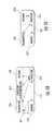
- FIG. 1Bis a graphical depiction of the radio sub-system of the aerial platform of some embodiments.
- FIG. 1Cis a graphical depiction of the radio sub-system of the ground terminal of the aerial platform based communications system of some embodiments.
- FIG. 2Ais a graphical depiction of a set of beams formed by two aerial platforms/UAVs on the ground.
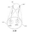
- FIG. 2Bis a graphical depiction of a set of beams formed according to an embodiment by three aerial platforms/UAVs on the ground.
- FIG. 2Cis a graphical depiction of a set of beams formed according to an embodiment by two aerial platforms/UAVs on the ground.
- FIG. 3Ais a graphical depiction of two UAVs providing coverage to the same area on the same frequency.
- FIG. 3Bis a graphical depiction of two UAVs providing coverage to the same area on the same frequency.
- the aerial platforms to which the embodiments of this disclosure applymay be drones, unmanned aerial vehicles (UAVs), balloons, blimps, airships, etc.
- the drone or UAVmay comprise propulsion systems, fuel systems, and onboard navigational and control systems.
- the dronecomprises a fixed wing fuselage in combination with a propeller, etc.
- the UAVcomprises a robocopter, propelled by a rotor.
- the UAVmay carry fuel onboard or function using electrical (e.g., battery powered) and/or solar energy.
- the terms “aerial platform” and “UAV”refer to any of the above mentioned platforms such as drones, balloons, blimps, airships, etc.
- UAVsUAVs
- drones, balloons, blimps, airships, etc. in the disclosurecan refer to aerial platforms in general or any other type of aerial platforms.
- FIG. 1Ashows one UAV 110 .
- Each UAV 110has a drone radio sub-system 112 , a message switch sub-system 116 , and at least one drone antenna aperture sub-system 114 that is configured to generate a “beam” or “footprint” of radio coverage.
- the exemplary block diagram of the radio sub-system 112 shown in FIG. 1Bconsists of five sub-systems: (1) a receiver 318 that demodulates and decodes the signal received from antenna sub-system 114 ; (2) a transmitter sub-system 316 that modulates the data received from a processor 314 and sends the resulting signal to a power amplifier (PA) sub-system 317 and then an antenna sub-system 114 ; (3) the processor sub-system 314 , which carries out functions such as configuring the receiver 318 and transmitter 316 sub-systems, processing the data received from the receiver 318 sub-system, determining the data to be transmitted through the transmitter sub-system 316 , as well as controlling the antenna sub-system 114 ; (4) a memory sub-system 312 that contains program code, configuration data, and system parameter information that are accessed by the processor 314 for execution; and (5) a gyroscope/accelerometer/GPS (Global Positioning System) sub-system 319 to determine the position coordinates and orientation angles
- each UAV 110covers an area on the ground.
- the coverage areamay have a radius of as low as a few tens of kilometers and as much as 200 km or more, although those of ordinary skill in the related arts will readily appreciate that smaller and/or greater coverage areas are possible.
- UAVs 110communicate with at least two kinds of ground terminals: one type is a user Ground Terminal (GT) 120 (see FIG. 1A ), which may include terminals at a home or enterprise that are configured to provide Internet connectivity to the home or enterprise; a second type is an Internet Gateway Terminal (GWT) 130 , which communicates with UAV 110 on paths 212 and 232 using a gateway radio sub-system module 132 and an antenna sub-system 134 .
- GTUser Ground Terminal
- GWTInternet Gateway Terminal
- GTs 120transmits and receives data on paths 222 and 212 , respectively, from the Internet 136 using the UAV 110 as an intermediary to the GWT 130 .
- the GWT 130 radio sub-system module 132may communicate with the Internet 136 by connecting via a local area network (LAN), local area wireless (e.g., Wi-Fi), Bluetooth, cellular, radio, infrared, or any other type of data connection.
- LANlocal area network
- Wi-Fiwireless local area wireless
- Bluetoothcellular, radio, infrared, or any other type of data connection.
- User devicessuch as personal computers and mobile devices can connect to the UAV 110 through a number of proxy device(s) in the network between the GT 120 and the user device.
- the UAV's 110 radio sub-systemaggregates traffic received from at least one GT (up to all GTs) 120 and sends the aggregated data to the Internet 136 via one of the GWTs.
- the GWTs 130may need to provide higher data rates from and to the UAVs 100 than the GTs 120 , accordingly the gain of the GWT antenna sub-system 134 may be larger than that of the GT 124 , and the GWT transmitter may transmit at higher power than the GT's 416 do.
- the GT 120has two main sub-systems, a ground terminal radio sub-system 122 , and a ground terminal antenna sub-system 124 .
- the GT radio sub-system 122consists of 4 sub-systems: (1) a receiver 418 that demodulates and decodes the signal from drone antenna sub-system 114 ; (2) a transmitter sub-system 416 modulates the data and sends the resulting signal through the antenna sub-system 124 ; (3) a processor sub-system 414 that carries out functions such as configuring the receiver 418 and transmitter 416 sub-systems, processing the data received from the receiver 418 sub-system, determining the data to be transmitted through the transmitter sub-system 416 , as well as controlling the antenna sub-system 124 ; and (4) a memory sub-system 412 that contains program code, configuration data, and system parameters information that are accessed by the processor 414 .
- Aerial platforms such as UAVs 110cruise in a three-dimensional area.
- the position of the aerial platform 110 with respect to the terminals on the groundchanges as the UAV 110 moves around in a circular/elliptical manner in its cruising orbit and also vertically within the “station keeping area” (i.e. the UAV's 110 highest orbit 610 and lowest orbit 612 ). If adjustments are not made to the beams generated by the UAV 110 based on movements of the UAV 110 , then as the UAV 110 moves vertically, the coverage area on the ground that is illuminated by the UAV's antenna sub-system 114 will change.
- FIG. 2Ais an exemplary diagram of the cruising area of a network consisting of two UAVs 110 - 1 and 110 - 2 .
- the suffixes 1 and 2are used to label the same attributes of the different UAVs in FIG. 2A .
- Top solid circles 610 - 1 and 610 - 2show the cruising orbit of the UAVs 110 - 1 and 110 - 2 at their highest possible altitude.
- the lower dotted circles 612 - 1 and 612 - 2show the cruising orbits at their lowest cruising altitude.
- a UAV 110will cruise around an orbit at a given altitude but at the same time will be slowly moving vertically up or down depending on time of day (so as to e.g., reduce power consumption, etc.). In addition to the vertical movement, the UAV 110 also rolls or pitches as it travels in its cruising orbit.
- Various embodiments of the present inventioncan have different orbital paths 610 of the UAV 110 .
- Path shapesmay comprise an elliptical or substantially circular orbit.
- Other paths 610 , 612include star patterned, clover, flower, FIG. 8 , or virtually any possible flight path.
- Orbits 610 , 612may also include ones that are vertical in nature or encompass three dimensional flight paths.
- orbits 610 , 612may also be random, or random within certain constraints or spatial boundaries, or include orbits with distinct angular corners (i.e., triangular, quadrilateral, or other multi-sided orbit).
- One set of embodiments in this disclosuredescribes systems and methods to optimize the network of beams formed on the ground by multiple adjacent UAVs 110 .
- Another set of embodimentsdescribe a UAV deployment scheme whereby multiple UAVs 110 may provide coverage to ground terminals 120 in the same coverage area on the same frequency band.
- FIG. 2Ashows an example where UAV 110 - 1 generates a set of beams 1 through 19 in the target coverage area 614 - 1 , and UAV 110 - 2 generates a set of beams 20 through 38 in its target coverage area 614 - 2 on the ground.
- the hexagonsshow the ideal coverage of each beam.
- Frequency reusei.e., frequencies allocated to a service that are reused in a regular pattern of areas or cells
- the available frequency bandwidthis divided into three bands and the three frequency bands are assigned to adjacent beams in such a way that no two neighboring beams within the coverage area of one UAV 110 use the same frequency band.
- the three different dotted circle types(dotted, dot-dashed, dashed) indicate beams that use different frequency bands.
- a frequency reuse of threereduces interference at adjacent beams and improves the data rate.
- the beams formed by the UAV antenna sub-system 114are typically designed to have a roll-off of 2 to 3 dB at the cell edge relative to the beam's peak gain at the center of the cell.
- Other embodimentsmay be designed to incorporate beams formed with a roll-off of greater or less than 2 to 3 dB from the beam's peak gain. The beams, therefore, cover a larger area than that shown by hexagonal shape cell but at lower gains.
- the UAV 110 and the ground terminal antenna sub-systems 124are comprised of two antenna polarization such as vertical and horizontal linear polarizations, or left and right circular polarizations.
- the UAV 110 and ground terminal radio sub-systems 124also comprise of two transmitter and two receiver chains, each of the transmitters and receivers connected to one of the two antenna polarizations.
- the UAV 110 and ground terminal radio sub-systems 124are capable of transmitting and receiving two data streams, one on each of the two antenna polarizations, resulting in a so called 2 ⁇ 2 Multiple Input Multiple Output (MIMO) configuration.
- MIMOMultiple Input Multiple Output
- Each pair of transmit/receive sub-system of the radio sub-systemis referred to as a transceiver in the sequel.
- the resulting 2 ⁇ 2 MIMO configuration as described abovemay result in almost doubling the system throughput, using the same amount of spectrum.
- a modified version of IEEE 802.11 air interface protocolalso known generically as Wireless Local Area Network (WLAN) and/or the trademarked name “Wi-Fi”, is used by the UAV 110 and ground terminal radio sub-systems 124 as the communications protocol.
- the UAV 110forms a number of beams to cover the target coverage area 614 on the ground.
- Each of the beams formed by the UAV 110uses a different transceiver to send and receive data from ground terminals 120 in that beam.
- the IEEE 802.11 specificationuses Carrier Sense Multiple Access/Collision Avoidance (CSMA/CA) protocol as a way to prevent user terminals from interfering with one another when they transmit data over the wireless medium.
- CSMA/CACarrier Sense Multiple Access/Collision Avoidance
- Embodiments of the present disclosuremay use the CSMA/CA framework as described in e.g., IEEE 802.11.
- CSMA/CAis an effective protocol for handling data transfer collisions over Wi-Fi for LAN where all user terminals are relatively close to the base station
- CSMA/CAmay be ineffective for handling transmissions in a point-to-multipoint system over long distances such as between UAVs 110 and the ground terminals 120 .
- Using CSMA/CA over long distances in a point-to-multipoint system between the UAV 110 and the ground terminals 120may be ineffective because ground terminals 120 that are closer to the UAV 110 will dominate the channel arbitration process since they will always be able to sense the channel availability faster than more remote terminals and thus be able to transmit before remote terminals do. This effect is sometimes also referred to as the “near-far” problem.
- the two communications linkscommunicate on the same frequency channel but at different times; thus, when radios are deployed in close proximity to one another, radio interference becomes an issue.
- TDDTime Division Duplex
- the different transmittersare not synchronized and the transceivers are a short distance apart, the received signal from one transmitter may be very strong and could severely degrade the performance for all of the radio receivers at the same location even if adjacent transceivers may be operating in different non-overlapping frequencies and have antennas pointed in different directions.
- the ground terminal 120 and the gateway transceivers 130can be placed in close proximity.
- the radio sub-systems at the ground terminals 120 , the gateways 130 and the UAV 110may run a custom Medium Access Control (MAC) layer on top of the IEEE 802.11 PHY.
- MACMedium Access Control
- the MAC layerwill handle the challenges of transmitting and receiving data frames over the wireless medium.
- all transceivers at the UAV 110must be synchronized so that they transmit almost at the same time and then go into receive mode almost at the same time.
- a timing signal from a GPS receiver 319 at the UAV 110is used to provide a common clock to all transceivers and thereby synchronizing the transceivers within the UAV 110 .
- one of the transceivers at the UAV 110acts as the master and sends its clock timing to the remaining transceivers to which they synchronize their clocks.
- the clock timingmay be sent from the master transceiver to other transceivers physically through wires to other transceivers within the UAV 110 ; or the master transceiver may send a beacon message that carries the master transceiver's clock timing and the remaining transceivers within the UAV 110 synchronize their clocks to the timing signal in the beacon message.
- timeis divided into intervals and each time interval is further divided into downlink and uplink sub-intervals. Each sub-interval is further divided into time slots.
- the first sub-interval in each intervalis dedicated to downlink transmissions and is referred to as the downlink sub-interval, where the transceiver at the UAV 110 corresponding to each beam transmits data to the different terminals within their beams.
- the transceiver at the UAV 110 communicating with ground terminals in a given beamtransmits data to different ground terminals 120 in a round robin manner during the downlink sub-interval.
- the ground terminals 120send their uplink bandwidth requirement to the UAV transceiver during one uplink sub-interval. Then, during the downlink sub-interval following the aforementioned uplink sub-interval, the UAV transmitter corresponding to a beam allocates time on the uplink to each terminal for the next uplink sub-interval.
- the ground terminals 120send data to the UAV transceiver of their beams based on the time allocated to each terminal 120 in the previous downlink sub-interval, and also send to the UAV transceiver their uplink bandwidth requirement for the next uplink sub-interval.
- certain time slotsare allocated to the ground terminals 120 where they send their uplink bandwidth requirement.
- the coverage area 614 - 1 as shown in FIG. 2Aconsists of three rings—the first ring having cell 1 , the second ring adding cells 2 through 7 around the first ring (cell 1 ), and the third ring adding cells 8 through 19 around the second ring—adding one more ring of cells and beams to the beam network of UAV 110 - 1 will add an additional 18 beams in the fourth ring around the third ring, resulting in a total of 37 beams in coverage area 614 - 1 .
- a fifth ring of beamswould add an additional 24 beams, resulting in a total of 61 beams in the circular footprint. Therefore, the number of rings of cells and beams used to cover the desired footprint of a UAV 110 depends on the required throughput and may be adjusted as desired or needed to effectuate appropriate coverage, consistent with the present disclosure.
- a UAV static beam forming mechanisme.g., where the UAV antenna sub-system 114 does not keep each beam pointed at a given location by either mechanical or electronic beam steering as the UAV 110 cruises in its orbit 614
- the beams formed by the UAV 110 on the groundwill move around within a circle (or other orbit) as the UAV 110 cruises.
- the beams shown within circles 614 - 1 and 614 - 2will rotate around the center of the coverage areas as the respective UAV 110 travels in its orbit.
- the ground terminalwill be switched to the beam with better coverage.
- the advantage of this type of static UAV beam formingis that it reduces UAV antenna sub-system 114 complexity.
- the beams formed by different UAVs 110may rotate on the ground at different rates because of different movements of the UAVs 110 .
- certain beams at the boundary between two different UAVs 110may end up using the same frequency band.
- the throughput at the boundary beams which use the same frequency bandmay be lower than that of the beams further inside each coverage area.
- One approach to improving the data rates at the boundary beams that use the same frequencieswould be to use the same frequency band in a Time Division Multiplex (TDM) manner between boundary beams of two UAVs 110 .
- TDMTime Division Multiplex
- terminals that are at the boundaries of beam 12 of UAV 110 - 1 and beam 37 of UAV 110 - 2may use the same frequency but at different times, where at a given time only one of the UAVs 110 is transmitting to terminals 120 in its coverage area.
- the available frequency spectrum in the same frequency boundary cellsis divided into two frequency sub-bands, and each sub-band is assigned to one of the neighboring boundary beams.
- a first frequency reuse factorcould be used (e.g., three (3)), but for cells at certain boundaries, the effective frequency reuse would be doubled (e.g., six (6)). In this manner, the beams at those boundaries can share the available frequency spectrum.
- the UAV radio sub-system 112allocates more transmit power to the beams with the reduced spectrum as that of other beams to compensate for the lowered throughput due to the division of the available frequency band.
- the additional transmit powerincreases the throughput per unit of spectrum bandwidth in the beams with less spectrum.
- the throughput of beams with larger coverage areas or higher traffic intensitymay also be increased by increasing the transmit power in the corresponding beams. In this manner, beam transmit power control is needed to adjust the throughput of the different beams based on the beams' coverage area, traffic requirements, and the amount of spectrum allocation.
- beam transmit power controlmay also be used to adjust the beam's power in response to rain fade. Therefore, the power amplifier (PA) 317 allocated to a beam will be adjusted over a certain dynamic range based on the abovementioned conditions.
- the processor sub-system 314has knowledge of each beam's traffic requirement, allocated frequency, coverage area, and/or atmospheric conditions. Based on the aforementioned information, the processor 314 determines the required power to be allocated to each beam, and instructs the radio sub-system 112 to adjust the power of the PA sub-system 317 for each beam accordingly.
- the dynamic range of the PA 317is large and the PA output versus input power may have linearity requirements.
- the power consumption of the PA 317may be large as the PA 317 must be biased to cover the large dynamic range.
- the PA biaswill be large resulting in high PA power consumption even when the actual PA transmit power is low. Since a UAVs' 110 available power may be limited, a mechanism for minimizing the power consumption of the PA 317 while allowing PA transmit power control over a wide dynamic range may be required.
- the required dynamic range of the power controlis divided into N power sub-ranges to minimize the PA power consumption.
- the PA 317is designed to include multiple bias points, where each PA bias point corresponds to one of the N power sub-ranges.
- the j-th PA bias point corresponding to the j-th power sub-rangewill be used by the PA 317 .
- the PA biasis optimized for the specific power sub-range at which the PA 317 is instructed by the power control algorithm to operate.
- the PA biasis also set lower, resulting in a lower PA power consumption than a PA 317 with single but larger bias.
- FIG. 2Billustrates an alternate configuration in which three sets of beams are formed by three adjacent UAVs 110 .
- three UAVs 110may cruise at different speeds, and that UAV antenna static beam forming is employed, then beams at the boundary of coverage areas 614 - 1 , 614 - 2 and 614 - 3 may at certain time use the same frequency band as discussed above.
- UAV beamsare typically designed to roll off by 2 to 3 dB at the cell edge on the ground. Consequently, the UAV beam still provides coverage but at lower gain beyond the cell's edge. More directly, beams formed by the UAV 110 can provide coverage to a larger area than specified by the hexagon boundaries in FIG. 2B , but with lower gain.
- the UAVsmay increase the power allocated to these beams to improve their throughput and compensate for their smaller frequency spectrum and larger coverage.
- Another embodiment of this disclosuredescribes systems and methods to manage sets of beams between multiple neighboring UAVs 110 when the UAV antenna sub-system 114 has the capability to dynamically steer its beams in response to UAV 110 movements where the beams stay fixed on predetermined ground positions.
- the dynamic beam formingmay be implemented using either mechanical or electronic beam steering mechanisms.
- the UAV antenna sub-system 114periodically receives UAV position location coordinates as well as UAV orientation angles from accelerometer/gyroscope/GPS sub-system 319 of the UAV 110 .
- the UAV antenna sub-system 114uses the updated UAV position coordinates and orientation angles to steer the beams to remain fixed in their assigned positions on the ground. Thus, the beams stay fixed to their assigned positions even when the UAV 110 moves.
- FIG. 2Cillustrates one embodiment in which the cells within coverage area 616 among multiple UAVs 110 are efficiently divided. This is followed by superimposing a frequency reuse, such as reuse of three, on the cells covering the area to be served by multiple UAVs 110 . Next, the cells 1 - 75 are divided between coverage areas of different UAVs 110 .
- FIG. 2Cillustrates how part of the ground coverage area is divided into two areas of 614 - 1 and 614 - 2 , each covered by a different UAV 110 .
- the coverage area provided by each UAV 110is approximated by a square.
- One possible principle in dividing cells between UAVs 110 corresponding to the two areas 614 - 1 and 614 - 2is to assign a cell to a UAV 110 if at least 50% of the cell's area is covered by the corresponding UAV 110 . For instance, cells 46 , 47 and 48 would not be assigned to coverage area 614 - 1 because 614 - 1 covers less than 50% of the aforementioned cells.
- cells 41 and 42are assigned to coverage area 614 - 1 and are severed by the UAV 110 that provides coverage to 614 - 1 . Cases in which 50% of a cell's area is covered may be resolved through arbitrary, predetermined, or alternating assignment (or time-averaged if not always fixed, as discussed immediately below). Various schemes for dividing coverage areas for different UAVs 110 can be used. The remainder of area 616 may be similarly assigned to other UAVs 110 .
- a cellwill not be assigned to a UAV 110 unless it can cover a supermajority of area (e.g. 75%) up to 100%.
- a UAV 110may be assigned a cell with less coverage (i.e. below 50%).
- embodimentsmay also use other criteria rather than just coverage area to determine whether a cell should be assigned to a particular UAV 110 such as the particulars of the UAVs 110 and their configurations, and/or network considerations (e.g., current usage, historic usage, predicted usage, etc.)
- the beam positionscan stay fixed as described in above embodiments or allowed to move away from their original positions for a length of time. If the UAV coordinates are updated slowly, the beam positions would also be adjusted accordingly. Depending on the connectivity demand associated with the particular ground positions, this configuration may reduce operating costs, e.g., battery life on the UAV 110 . Infrastructures or areas with sensitive resource considerations may thereby opt to increase the update periods to reduce upkeep costs.
- FIGS. 3A and 3Ba UAV deployment strategy is described whereby multiple UAVs 110 may provide coverage to their respective ground terminals in the same coverage area and on the same frequency band.
- two different operatorswould be allowed to provide broadband service to their respective customers in the same geographic area using the same spectrum.
- FIG. 3Ashows two UAVs 110 - 1 and 110 - 2 cruising in orbits 610 - 1 and 610 - 2 .
- the coverage areas 614 - 1 and 614 - 2 of the two UAVs 110 - 1 and 110 - 2overlap as shown by the two circles with different types of dashed lines.
- Separation between UAVs 110 - 1 and 110 - 2is achieved by spacing the cruising orbit of the two UAVs 110 - 1 and 110 - 2 and also placing the UAVs 110 - 1 and 110 - 2 in their respective cruising orbits 610 - 1 and 610 - 2 to further increase the separation between the UAVs 110 - 1 and 110 - 2 .
- UAVsmay overlap in their cruising orbits, as depicted in FIG. 3B .
- Both UAVs 110 - 1 and 110 - 2share a same cruising orbit 610 , but the two UAVs 110 - 1 and 110 - 2 cruise in such a way so as to maintain a certain separation distance between the two UAVs 110 - 1 and 110 - 2 .
- Each UAV 110 - 1 and 110 - 2provides connectivity to a different set of ground terminals 120 .
- FIGS. 3A and 3Bshow ground terminal 120 - 1 communicating with UAV 110 - 1 , and ground terminal 120 - 2 communicating with UAV 110 - 2 .
- ground terminals 120 communicating with a first UAV 110 - 1must deploy directional antennas pointed toward the first UAV 110 - 1 in order to attenuate the interference received from signals transmitted by the second UAV 110 - 2 .
- Ground terminal 120 - 1points its beam toward UAV 110 - 1 . If there is a spatial separation between the two UAVs 110 - 1 and 110 - 2 , and the antenna beam of the ground terminal 120 - 1 is chosen to be adequately narrow, then the sidelobe of the ground terminal 120 - 1 antenna beam will attenuate the signal received from UAV 110 - 2 .
- the required ground terminal 110 - 1 antenna sidelobe attenuation toward UAV 110 - 2depends on the desired Signal to Interference ratio (S/I) at ground terminal 120 - 1 .
- S/ISignal to Interference ratio
- the required beamwidth of the ground terminal antenna beamalso depends on the spatial separation of the two UAVs 110 - 1 and 110 - 2 . The closer the two UAVs 110 - 1 and 110 - 2 are, the narrower the beamwidth of the ground terminal must be in order to maintain the interference from the interfering UAV 110 below a threshold.
- the required beamwidth of the ground terminal beammay be computed for each ground terminal location in the specified coverage area 614 .
- the beamwidth of the ground terminal antenna beamis chosen to be the minimum beamwidth from among all ground terminal locations. In other embodiments, more than two UAVs 110 - 1 and 110 - 2 may share the same cruising orbit 610 .
- the different service providersneed to agree on the target S/I, and then compute the required UAV separation and ground terminal antenna beamwidth/pattern to achieve the target S/I.
- the required UAV separation and ground terminal antenna patternwould be specified as rules to be followed by the different UAV service providers to achieve the target S/I performance requirement.
- cruising orbits 610 - 1 and 610 - 2 of UAVs 110 - 1 and 110 - 2may overlap partially, as long as the UAVs are positioned so as to not cross paths at an intersection of cruising orbits 610 - 1 and 610 - 2 .
- the beamwidth for the ground terminal antenna beamsmay not be required to be as narrow as in the configuration of FIG. 3B because the UAVs 110 - 1 and 110 - 2 may be adequately separated. This is particularly true if UAVs 110 - 1 and 110 - 2 orbit in a manner that maintains a substantially fixed distance between them (e.g., UAVs 110 - 1 and 110 - 2 orbit in the same direction and in parallel).
- the beamwidth of the ground terminal beamwill stay relatively constant reducing interference from/to other UAVs 110 - 1 and 110 - 2 .
- the distances between UAVs 110 - 1 and 110 - 2continually varies (e.g., UAVs 110 - 1 and 110 - 2 are orbiting at different speeds, and at different angles), then there will be a dynamically changing range of distances between the UAVs 110 - 1 and 110 - 2 .
- the UAVs 110 - 1 and 110 - 2must compensate by adjusting their beamwidths based on the varying distances created by uneven orbit paths.
- the ground terminals communicating boundary coverage area cell of one UAVe.g., cell 11 of UAV 110 - 1
- the ground terminals communicating boundary coverage area cell of one UAVcan receive negligible interference from the neighboring UAVs 110 - 2 and 110 - 3 even if the neighboring cells 27 and 54 are using the same frequency as that of cell 11 . Consequently, cells at the boundary of coverage areas of multiple UAVs may use the same frequency band with negligible interference to the GTs in those cells and without needing to further divide time or frequency among the boundary cells.
- UAVs 110may be able to communicate with other UAVs 110 (or sense the presence or position of other UAVs 110 ) to determine an appropriate distance, velocity, and PA output. It is contemplated that UAVs 110 can change position and/or orbit depending on the position or movements of other UAVs 110 . For instance, if one of the UAVs 110 were to go offline, other UAVs 110 can compensate. Additionally, management of a UAV 110 could occur from a terminal on the ground and may be manual or automatic. It will be recognized that while certain aspects of the disclosure are described in terms of a specific sequence of steps of a method, these descriptions are only illustrative of the broader methods of the disclosure, and may be modified as required by the particular application. Certain steps may be rendered unnecessary or optional under certain circumstances. Additionally, certain steps or functionality may be added to the disclosed embodiments, or the order of performance of two or more steps permuted. All such variations are considered to be encompassed within the disclosure and claims herein.
Landscapes
- Engineering & Computer Science (AREA)
- Computer Networks & Wireless Communication (AREA)
- Signal Processing (AREA)
- Physics & Mathematics (AREA)
- Astronomy & Astrophysics (AREA)
- Aviation & Aerospace Engineering (AREA)
- General Physics & Mathematics (AREA)
- Mobile Radio Communication Systems (AREA)
Abstract
Description
Claims (21)
Priority Applications (1)
| Application Number | Priority Date | Filing Date | Title |
|---|---|---|---|
| US15/257,640US9800320B2 (en) | 2014-11-06 | 2016-09-06 | Beam forming and pointing in a network of unmanned aerial vehicles (UAVs) for broadband access |
Applications Claiming Priority (4)
| Application Number | Priority Date | Filing Date | Title |
|---|---|---|---|
| US201462076360P | 2014-11-06 | 2014-11-06 | |
| US201462080856P | 2014-11-17 | 2014-11-17 | |
| US14/626,698US9712228B2 (en) | 2014-11-06 | 2015-02-19 | Beam forming and pointing in a network of unmanned aerial vehicles (UAVs) for broadband access |
| US15/257,640US9800320B2 (en) | 2014-11-06 | 2016-09-06 | Beam forming and pointing in a network of unmanned aerial vehicles (UAVs) for broadband access |
Related Parent Applications (1)
| Application Number | Title | Priority Date | Filing Date |
|---|---|---|---|
| US14/626,698DivisionUS9712228B2 (en) | 2014-11-06 | 2015-02-19 | Beam forming and pointing in a network of unmanned aerial vehicles (UAVs) for broadband access |
Publications (2)
| Publication Number | Publication Date |
|---|---|
| US20170063443A1 US20170063443A1 (en) | 2017-03-02 |
| US9800320B2true US9800320B2 (en) | 2017-10-24 |
Family
ID=55909867
Family Applications (3)
| Application Number | Title | Priority Date | Filing Date |
|---|---|---|---|
| US14/626,698ActiveUS9712228B2 (en) | 2014-11-06 | 2015-02-19 | Beam forming and pointing in a network of unmanned aerial vehicles (UAVs) for broadband access |
| US15/257,649ActiveUS9866312B2 (en) | 2014-11-06 | 2016-09-06 | Beam forming and pointing in a network of unmanned aerial vehicles (UAVs) for broadband access |
| US15/257,640ActiveUS9800320B2 (en) | 2014-11-06 | 2016-09-06 | Beam forming and pointing in a network of unmanned aerial vehicles (UAVs) for broadband access |
Family Applications Before (2)
| Application Number | Title | Priority Date | Filing Date |
|---|---|---|---|
| US14/626,698ActiveUS9712228B2 (en) | 2014-11-06 | 2015-02-19 | Beam forming and pointing in a network of unmanned aerial vehicles (UAVs) for broadband access |
| US15/257,649ActiveUS9866312B2 (en) | 2014-11-06 | 2016-09-06 | Beam forming and pointing in a network of unmanned aerial vehicles (UAVs) for broadband access |
Country Status (3)
| Country | Link |
|---|---|
| US (3) | US9712228B2 (en) |
| CN (1) | CN107113053A (en) |
| WO (1) | WO2016073863A1 (en) |
Cited By (3)
| Publication number | Priority date | Publication date | Assignee | Title |
|---|---|---|---|---|
| US20180019516A1 (en)* | 2016-07-15 | 2018-01-18 | Qualcomm Incorporated | Dynamic Beam Steering for Unmanned Aerial Vehicles |
| US11310806B1 (en) | 2020-12-01 | 2022-04-19 | T-Mobile Usa, Inc. | Drive test analysis |
| US11675041B2 (en) | 2020-06-04 | 2023-06-13 | T-Mobile Usa, Inc. | Locating signal interference using unmanned aerial vehicles |
Families Citing this family (58)
| Publication number | Priority date | Publication date | Assignee | Title |
|---|---|---|---|---|
| US9859972B2 (en) | 2014-02-17 | 2018-01-02 | Ubiqomm Llc | Broadband access to mobile platforms using drone/UAV background |
| US9571180B2 (en) | 2014-10-16 | 2017-02-14 | Ubiqomm Llc | Unmanned aerial vehicle (UAV) beam forming and pointing toward ground coverage area cells for broadband access |
| US9712228B2 (en) | 2014-11-06 | 2017-07-18 | Ubiqomm Llc | Beam forming and pointing in a network of unmanned aerial vehicles (UAVs) for broadband access |
| US9715009B1 (en) | 2014-12-19 | 2017-07-25 | Xidrone Systems, Inc. | Deterent for unmanned aerial systems |
| US9689976B2 (en) | 2014-12-19 | 2017-06-27 | Xidrone Systems, Inc. | Deterent for unmanned aerial systems |
| US9590720B2 (en)* | 2015-05-13 | 2017-03-07 | Ubiqomm Llc | Ground terminal and gateway beam pointing toward an unmanned aerial vehicle (UAV) for network access |
| US9660718B2 (en) | 2015-05-13 | 2017-05-23 | Ubiqomm, LLC | Ground terminal and UAV beam pointing in an unmanned aerial vehicle (UAV) for network access |
| IL256934B (en) | 2015-07-27 | 2022-07-01 | Genghiscomm Holdings Llc | Airborne relays in cooperative multiple input and multiple output systems |
| CN108353081B (en) | 2015-09-28 | 2021-01-19 | 13部门有限公司 | Device and method for detecting and confronting remote-controlled vehicle and storage medium |
| US9734684B2 (en)* | 2016-01-04 | 2017-08-15 | International Business Machines Corporation | Perimeter monitoring using autonomous drones |
| US10116377B2 (en)* | 2016-01-06 | 2018-10-30 | Google Llc | Dynamic forward error correction bypass in a digital communications system |
| US20170227470A1 (en)* | 2016-02-04 | 2017-08-10 | Proxy Technologies, Inc. | Autonomous vehicle, system and method for structural object assessment and manufacture thereof |
| RU2733905C2 (en)* | 2016-04-18 | 2020-10-08 | Рхомбус Сыстемс Гроуп, Инц. | System for communication with drones using two frequency bands |
| US9853713B2 (en) | 2016-05-06 | 2017-12-26 | Ubiqomm Llc | Unmanned aerial vehicle (UAV) beam pointing and data rate optimization for high throughput broadband access |
| CN105818961A (en)* | 2016-05-13 | 2016-08-03 | 黄剑锋 | Multi-antenna and fuselage integrated unmanned aerial vehicle |
| US9913278B2 (en)* | 2016-06-06 | 2018-03-06 | Google Llc | Systems and methods for dynamically allocating wireless service resources consonant with service demand density |
| US10049587B2 (en)* | 2016-07-01 | 2018-08-14 | Intel IP Corporation | Unmanned aerial vehicle navigation |
| WO2018009044A1 (en)* | 2016-07-07 | 2018-01-11 | Lg Electronics Inc. | Method and apparatus for transceiving a signal in a wireless communication system supporting zone-based communication |
| WO2018042927A1 (en)* | 2016-09-02 | 2018-03-08 | ソニー株式会社 | Circuit, terminal device, base station device and method |
| US20180191439A1 (en)* | 2016-09-08 | 2018-07-05 | Equinox Innovative Systems Llc | Drone-based radio-over-fiber system |
| US10313686B2 (en) | 2016-09-20 | 2019-06-04 | Gopro, Inc. | Apparatus and methods for compressing video content using adaptive projection selection |
| US20180097560A1 (en)* | 2016-10-05 | 2018-04-05 | Ubiqomm, LLC | Apparatus and methods to provide communications to aerial platforms |
| US10020872B2 (en)* | 2016-10-11 | 2018-07-10 | T-Mobile Usa, Inc. | UAV for cellular communication |
| US9866313B1 (en) | 2016-12-14 | 2018-01-09 | T-Mobile Usa, Inc. | UAV cellular communication service delivery |
| US10249948B2 (en)* | 2016-12-09 | 2019-04-02 | The Boeing Company | Phased array antennas for high altitude platforms |
| US10304343B2 (en) | 2017-02-24 | 2019-05-28 | At&T Mobility Ii Llc | Flight plan implementation, generation, and management for aerial devices |
| US10090909B2 (en) | 2017-02-24 | 2018-10-02 | At&T Mobility Ii Llc | Maintaining antenna connectivity based on communicated geographic information |
| JP6580082B2 (en)* | 2017-03-21 | 2019-09-25 | ソフトバンク株式会社 | Communication system, remote control device, levitation body, and method of using levitation body |
| US10418694B2 (en) | 2017-03-22 | 2019-09-17 | At&T Mobility Ii Llc | Antenna system for unmanned aerial vehicle |
| US11009867B1 (en)* | 2017-07-28 | 2021-05-18 | Rockwell Collins, Inc. | Low-cost distributed multifunction radio frequency (MFRF) swarming unmanned aircraft systems (UAS) |
| US11190952B2 (en)* | 2017-08-31 | 2021-11-30 | Mitsubishi Electric Corporation | Setting beam direction for a mobile terminal and a flying object |
| SE1751148A1 (en)* | 2017-09-18 | 2019-03-19 | Icomera Ab | Wireless communication system for aircrafts |
| US11032022B1 (en) | 2017-10-11 | 2021-06-08 | Genghiscomm Holdings, LLC | Detection, analysis, and countermeasures for automated and remote-controlled devices |
| CN111386658B (en)* | 2017-11-17 | 2022-02-18 | 上海诺基亚贝尔股份有限公司 | Unmanned aerial vehicle and power control method thereof |
| TWI656758B (en)* | 2017-12-01 | 2019-04-11 | 財團法人工業技術研究院 | Communication terminal device for aircraft and mobile communication method thereof |
| US10907940B1 (en) | 2017-12-12 | 2021-02-02 | Xidrone Systems, Inc. | Deterrent for unmanned aerial systems using data mining and/or machine learning for improved target detection and classification |
| CN108135002B (en)* | 2017-12-22 | 2021-12-21 | 南京航空航天大学 | Unmanned aerial vehicle frequency spectrum resource allocation method based on block coordinate reduction |
| CN107919899B (en)* | 2017-12-27 | 2024-01-26 | 成都西科微波通讯有限公司 | Cloud relay communication system |
| CN109982363A (en)* | 2017-12-28 | 2019-07-05 | 株式会社Ntt都科摩 | Wireless communications method and corresponding communication equipment |
| CN110011716A (en)* | 2018-01-04 | 2019-07-12 | 杭州海康机器人技术有限公司 | A kind of earth station |
| JP6643409B2 (en) | 2018-06-22 | 2020-02-12 | Hapsモバイル株式会社 | Flight formation and communication area control of air vehicles that provide wireless communication services |
| JP7037055B2 (en)* | 2018-06-29 | 2022-03-16 | 日本電信電話株式会社 | Mobile station control method and mobile station control device |
| KR101937406B1 (en) | 2018-06-29 | 2019-01-10 | 한화시스템(주) | Mobile base station system |
| CN108880662B (en) | 2018-07-16 | 2020-04-10 | 深圳大学 | Wireless information and energy transmission optimization method based on unmanned aerial vehicle |
| US20200106818A1 (en)* | 2018-09-28 | 2020-04-02 | Quoc Luong | Drone real-time interactive communications system |
| JP6663468B1 (en)* | 2018-10-15 | 2020-03-11 | Hapsモバイル株式会社 | Control device, program, system and control method |
| CN109471453B (en)* | 2018-12-25 | 2022-05-10 | 长春理工大学 | Unmanned aerial vehicle relay station cruise system |
| JP7296236B2 (en) | 2019-03-29 | 2023-06-22 | Hapsモバイル株式会社 | Multi-feeder link configuration and its control in HAPS communication system |
| EP3949163B1 (en)* | 2019-04-04 | 2025-08-27 | Telefonaktiebolaget LM Ericsson (publ) | Technique for classifying a ue as an aerial ue |
| TWI710166B (en) | 2019-04-12 | 2020-11-11 | 國立交通大學 | Antenna adjustment device and method of mobile carrier |
| US10805807B1 (en) | 2019-12-05 | 2020-10-13 | Loon Llc | Coordination of spectrum allocation and interference avoidance among high-altitude networks |
| CN112105077B (en)* | 2020-09-23 | 2021-09-03 | 西安科技大学 | Large-scale MIMO system UAV relay communication method based on SWIPT technology |
| US11711134B2 (en) | 2021-03-15 | 2023-07-25 | Nokia Technologies Oy | Autonomous beam switch in HAPS coverage |
| CN113993098B (en)* | 2021-09-15 | 2024-02-13 | 北京邮电大学 | Power control factor setting method for 6G unmanned aerial vehicle user |
| WO2023075221A1 (en)* | 2021-10-29 | 2023-05-04 | 한국전자통신연구원 | Method and device for configuring cell area in communication system |
| US12231993B2 (en) | 2022-02-24 | 2025-02-18 | Microavia International Limited | Wireless bidirectional communication network for UAV |
| CN115314099B (en)* | 2022-06-10 | 2023-08-01 | 北京邮电大学 | Method and system for enhancing communication coverage network of UAV base station |
| CN119854808B (en)* | 2025-03-24 | 2025-05-27 | 中国电子科技集团公司第十研究所 | A cognitive anti-interference method for hierarchical linkage of unmanned swarms |
Citations (131)
| Publication number | Priority date | Publication date | Assignee | Title |
|---|---|---|---|---|
| US3568197A (en) | 1969-12-05 | 1971-03-02 | Nasa | Antenna array phase quadrature tracking system |
| US3780303A (en) | 1971-09-20 | 1973-12-18 | Texaco Inc | Pulsed neutron logging with background compensation |
| US3891985A (en) | 1961-02-21 | 1975-06-24 | Sperry Rand Corp | Drone control system with pulse position encoding |
| US4209695A (en) | 1976-12-06 | 1980-06-24 | Texaco Inc. | Detection of impurities in fluid flowing in refinery pipeline or oil production operations using nuclear techniques |
| US4278885A (en) | 1978-05-04 | 1981-07-14 | Outokumpu Oy | Apparatus for measuring the concentrations of elements in a material by the capture gamma method |
| US4317993A (en) | 1978-01-16 | 1982-03-02 | Schlumberger Technology Corporation | Methods and apparatus for constituent analysis of earth formations |
| US4365154A (en) | 1980-03-06 | 1982-12-21 | Texaco Inc. | Detection of impurities in a fluid containing free gas using nuclear techniques |
| US4387302A (en) | 1980-12-30 | 1983-06-07 | Mobil Oil Corporation | Measuring of gamma-ray energy due to inelastic neutron scattering |
| US4499380A (en) | 1982-10-21 | 1985-02-12 | Esso Resources Canada, Ltd. | Apparatus and method for determining the hydrogen content of a substance |
| JPS6141979A (en) | 1984-08-06 | 1986-02-28 | Nec Corp | Radio wave receiving device |
| US4851687A (en) | 1987-01-13 | 1989-07-25 | Scientific Innovations, Inc. | Detection of nitrogen in explosives |
| US5021664A (en) | 1990-06-22 | 1991-06-04 | Tennelec/Nucleus, Inc. | Method and apparatus for correcting the energy resolution of ionizing radiation spectrometers |
| US5068532A (en) | 1987-11-12 | 1991-11-26 | United Kingdom Atomic Energy Authority | Analysis using neutrons |
| US5076993A (en) | 1990-01-12 | 1991-12-31 | Science Applications International Corporation | Contraband detection system using direct imaging pulsed fast neutrons |
| US5098640A (en) | 1990-01-10 | 1992-03-24 | Science Applications International Corporation | Apparatus and method for detecting contraband using fast neutron activation |
| US5239568A (en) | 1990-10-29 | 1993-08-24 | Scinticor Incorporated | Radiation collimator system |
| US5241544A (en) | 1991-11-01 | 1993-08-31 | Motorola, Inc. | Multi-channel tdm communication system slot phase correction |
| US5521817A (en) | 1994-08-08 | 1996-05-28 | Honeywell Inc. | Airborne drone formation control system |
| US5561434A (en) | 1993-06-11 | 1996-10-01 | Nec Corporation | Dual band phased array antenna apparatus having compact hardware |
| US5712885A (en) | 1994-06-09 | 1998-01-27 | Commonwealth Scientific And Industrial Research Organisation | Determination of pre-reduction degree in iron ore materials |
| US5832379A (en) | 1990-03-19 | 1998-11-03 | Celsat America, Inc. | Communications system including control means for designating communication between space nodes and surface nodes |
| US5995494A (en) | 1996-07-17 | 1999-11-30 | Nec Corporation | Data communication using network DCE and modified channel associated signaling |
| US6018659A (en) | 1996-10-17 | 2000-01-25 | The Boeing Company | Airborne broadband communication network |
| US6034634A (en) | 1997-10-24 | 2000-03-07 | Telefonaktiebolaget L M Ericsson (Publ) | Terminal antenna for communications systems |
| US6044323A (en) | 1997-10-20 | 2000-03-28 | Motorola, Inc. | Satellite based commercial and military intercity and intercontinental air traffic control |
| US6061562A (en)* | 1997-10-30 | 2000-05-09 | Raytheon Company | Wireless communication using an airborne switching node |
| US6108538A (en) | 1997-12-01 | 2000-08-22 | Motorola, Inc. | Method and apparatus for dynamically controlling hand-off thresholds in a satellite cellular communication system |
| US6144032A (en) | 1998-05-07 | 2000-11-07 | Gazdzinski; Robert F. | Method and apparatus for measuring the condition of degradable components |
| CA2316440A1 (en) | 1999-08-31 | 2001-02-28 | Lucent Technologies Inc. | System for performing handoffs using location information for a wireless unit |
| US6256476B1 (en) | 1998-06-25 | 2001-07-03 | Conexant Systems, Inc. | Power management for a telephone system by dynamically adjusting transmission power |
| US6281838B1 (en) | 1999-04-30 | 2001-08-28 | Rockwell Science Center, Llc | Base-3 switched-line phase shifter using micro electro mechanical (MEMS) technology |
| US20020061730A1 (en) | 1994-07-22 | 2002-05-23 | Nicholas Hart | Multi-beam TDMA satellite mobile communications system |
| US20020168974A1 (en) | 1999-04-29 | 2002-11-14 | Rosen Harold A. | Satellite transmission system with adaptive transmission loss compensation |
| US6513758B1 (en) | 2000-08-21 | 2003-02-04 | Hughes Electronics Corporation | High altitude platform control system |
| US20030040274A1 (en) | 2001-06-06 | 2003-02-27 | Jerry Dai | Uplink power control system for satellite communication system employing on-board satellite processing and fade estimation |
| US20030095067A1 (en) | 2001-11-09 | 2003-05-22 | Howell James M. | Beamformer for multi-beam receive antenna |
| US6594509B1 (en) | 1999-04-01 | 2003-07-15 | Matsushita Electric Industrial Co., Ltd. | Array-antenna radio communication apparatus |
| US6628941B2 (en) | 1999-06-29 | 2003-09-30 | Space Data Corporation | Airborne constellation of communications platforms and method |
| US20030223354A1 (en) | 2002-05-30 | 2003-12-04 | Denso Corporation | SINR measurement method for OFDM communications systems |
| US20040038658A1 (en) | 2002-08-23 | 2004-02-26 | Gurelli Mehmet Izzet | Wireless communication data rate control prediction method and system |
| US6718161B1 (en) | 2000-06-05 | 2004-04-06 | Northrop Grumman Corporation | Apparatus and method for reducing latency and buffering associated with multiple access communications systems |
| US6756937B1 (en) | 2000-06-06 | 2004-06-29 | The Directv Group, Inc. | Stratospheric platforms based mobile communications architecture |
| US20040152480A1 (en) | 2002-11-22 | 2004-08-05 | Telefonaktiebolaget Lm Ericsson (Publ) | Method and apparatus for generating a neighbor cell list |
| US6856803B1 (en) | 2000-06-26 | 2005-02-15 | Motorola, Inc. | Method for maintaining candidate handoff list for airborne cellular system |
| US20050035897A1 (en) | 2003-08-14 | 2005-02-17 | Sensis Corporation | Target localization using TDOA distributed antenna |
| US6873301B1 (en) | 2003-10-07 | 2005-03-29 | Bae Systems Information And Electronic Systems Integration Inc. | Diamond array low-sidelobes flat-plate antenna systems for satellite communication |
| US20050107077A1 (en) | 2003-11-14 | 2005-05-19 | Hintermeier Gary P. | Command station for mobile radio networks |
| US20050108374A1 (en) | 2003-11-14 | 2005-05-19 | Pierzga Wayne F. | Airborne radio relay system |
| US20050143005A1 (en)* | 2003-12-29 | 2005-06-30 | Peersat Llc. | Inter-satellite crosslink communications system, apparatus, method and computer program product |
| US20050243005A1 (en) | 2004-04-27 | 2005-11-03 | Gholamreza Rafi | Low profile hybrid phased array antenna system configuration and element |
| US20050264438A1 (en) | 2004-05-28 | 2005-12-01 | Time Domain Corporation | Apparatus and method for detecting moving objects |
| US20060009262A1 (en) | 2004-07-09 | 2006-01-12 | The Boeing Company | Avionic base station controller (ABSC) for aircraft-based cellular communications |
| US20060063566A1 (en) | 2002-12-12 | 2006-03-23 | Nec Corporation | Multi-beam antenna reception device and multi-beam reception method |
| US7095376B1 (en) | 2004-11-30 | 2006-08-22 | L3 Communications Corporation | System and method for pointing and control of an antenna |
| US20060238411A1 (en) | 2004-05-28 | 2006-10-26 | Time Domain Corporation | System and method for spatially diverse radar signal processing |
| US20070032246A1 (en) | 2005-08-03 | 2007-02-08 | Kamilo Feher | Air based emergency monitor, multimode communication, control and position finder system |
| US20070090990A1 (en)* | 2005-10-20 | 2007-04-26 | Kinetx, Inc. | Active imaging using satellite communication system |
| US7212170B1 (en) | 2005-05-12 | 2007-05-01 | Lockheed Martin Corporation | Antenna beam steering via beam-deflecting lens and single-axis mechanical rotator |
| US20070184849A1 (en) | 2006-01-20 | 2007-08-09 | Act Technologies, Llc | Systems and Methods for Satellite Forward Link Transmit Diversity Using Orthagonal Space Coding |
| US20070224931A1 (en) | 2003-02-14 | 2007-09-27 | Kabushiki Kaisha Toshiba | Communication network for indoor environment |
| US20070230419A1 (en) | 2006-03-31 | 2007-10-04 | Sundar Raman | QoS signaling to support fairness |
| US20070281705A1 (en) | 2006-06-02 | 2007-12-06 | Bosenbecker Raymond W | Airborne Emergency Cell Phone Router |
| US20080090606A1 (en) | 2006-10-16 | 2008-04-17 | Samsung Electronics Co., Ltd. | Method for selecting receiver mode of mobile terminal with two receivers |
| US20080117858A1 (en) | 2006-11-21 | 2008-05-22 | Honeywell International Inc. | System and method for transmitting information using aircraft as transmission relays |
| US20080233865A1 (en) | 2007-03-21 | 2008-09-25 | Com Dev International Ltd. | Multi-beam communication system and method |
| US20090092072A1 (en) | 2005-04-28 | 2009-04-09 | Matsushita Electric Industrial Co., Ltd. | Communication relay apparatus and communication relay method |
| US20090209277A1 (en) | 2008-02-19 | 2009-08-20 | Gilat Satellite Networks, Ltd. | Satellite Redundancy for Critical Applications |
| US20090219912A1 (en) | 2005-08-26 | 2009-09-03 | Matsushita Electric Industrial Co., Ltd. | Scheduling depending on quality of service and channel properties |
| US20090296663A1 (en) | 2008-05-30 | 2009-12-03 | Alcatel-Lucent Via The Electronic Patent Assignment System (Epas) | Method of and base station for controlling beam forming in a mobile cellular network |
| US20090295485A1 (en)* | 2008-05-27 | 2009-12-03 | Motorola, Inc. | Dynamically biasing class ab power amplifiers over a range of output power levels |
| US20100085236A1 (en) | 2008-10-07 | 2010-04-08 | Honeywell International Inc. | Transponder-based beacon transmitter for see and avoid of unmanned aerial vehicles |
| US20100172299A1 (en) | 2007-06-19 | 2010-07-08 | Patrick Fischer | Enhancement of lte random access procedure |
| US7777674B1 (en) | 2008-08-20 | 2010-08-17 | L-3 Communications, Corp. | Mobile distributed antenna array for wireless communication |
| US20100224732A1 (en) | 2006-06-09 | 2010-09-09 | Insitu, Inc. | Wirelessly controlling unmanned aircraft and accessing associated surveillance data |
| US20100273504A1 (en) | 2009-04-22 | 2010-10-28 | Trueposition, Inc. | Network Autonomous Wireless Location System |
| US20100284377A1 (en) | 2006-07-28 | 2010-11-11 | Qualcomm Incorporated | Method and Apparatus For Sending Signaling For Data Transmission In A Wireless Communication System |
| US20100290412A1 (en) | 2008-02-05 | 2010-11-18 | Joon Kui Ahn | method of determining a size of a data packet advantageous for transmitting and restransmitting the data packet |
| US20110032149A1 (en) | 2009-08-06 | 2011-02-10 | Leabman Michael A | System and Methods for Antenna Optimization for Wireless Broadband Communication |
| US20110103293A1 (en) | 2009-10-30 | 2011-05-05 | Paragon Communication Solutions, Inc. | Internet based partitioning wireless communication system |
| US20110122024A1 (en) | 2008-07-25 | 2011-05-26 | Fraunhofer-Gesellschaft zur Forderng der angewandt forschung E.V | Device and method for determining the distance and/or orientation of a moveable object |
| US20110142150A1 (en) | 2003-08-13 | 2011-06-16 | Qualcomm Incorporated | User specific downlink power control channel q-bit |
| US20110182230A1 (en) | 2008-09-04 | 2011-07-28 | Michael Ohm | Systems and method for providing in-flight broadband mobile communication services |
| EP2369361A1 (en) | 2008-05-29 | 2011-09-28 | Cambridge Consultants Limited | Radar system and method |
| US20110286325A1 (en) | 2010-05-18 | 2011-11-24 | Qualcomm Incorporated | Hybrid satellite and mesh network system for aircraft and ship internet service |
| US20110286372A1 (en) | 2009-11-17 | 2011-11-24 | Qualcomm Incorporated | Efficient method for determining a preferred antenna pattern |
| US8078162B2 (en) | 2007-10-10 | 2011-12-13 | Battelle Energy Alliance, Llc | Airborne wireless communication systems, airborne communication methods, and communication methods |
| US8116763B1 (en) | 2009-09-02 | 2012-02-14 | The United States Of America As Represented By The Secretary Of The Navy | Airborne basestation |
| US20120052828A1 (en) | 2010-08-31 | 2012-03-01 | Verizon Patent And Licensing Inc. | Beam selection in a multiple beam antenna in a fixed wireless cpe |
| US20120119953A1 (en) | 2008-11-04 | 2012-05-17 | Kenichi Hosoya | Control method of wireless communication system, wireless communication system, adjustment method of array weight vector, and wireless communication device |
| US8183999B1 (en) | 2009-01-07 | 2012-05-22 | L-3 Communications, Corp. | Emergency locating system and method using spread-spectrum transceiver |
| US8190147B2 (en) | 2008-06-20 | 2012-05-29 | Honeywell International Inc. | Internetworking air-to-air network and wireless network |
| US20120150364A1 (en) | 2010-12-09 | 2012-06-14 | Tillotson Brian J | Unmanned vehicle and system |
| US20120202430A1 (en) | 2011-02-09 | 2012-08-09 | Qualcomm Incorporated | High data rate aircraft to ground communication antenna system |
| US20120235863A1 (en) | 2008-02-21 | 2012-09-20 | David Erdos | System and method for optimized unmanned vehicle communication using telemetry |
| US20130040655A1 (en) | 2011-08-10 | 2013-02-14 | Qualcomm Incorporated | Maintenance of mobile device rf beam |
| US20130070677A1 (en)* | 2011-09-21 | 2013-03-21 | Spatial Digital Systems | Concurrent airborne communication methods and systems |
| US20130109299A1 (en) | 2011-10-31 | 2013-05-02 | Hughes Networks Systems, Llc | System and method for gateway rf diversity using a configurable spot beam satellite |
| US20130155847A1 (en) | 2011-12-16 | 2013-06-20 | Samsung Electronics Co., Ltd. | Methods and apparatus to enhance reliability in millimeter wave wideband communications |
| US20130156021A1 (en) | 2011-12-19 | 2013-06-20 | Alcatel-Lucent Usa Inc. | Large-Scale Antenna Method And Apparatus Of Wireless Communication With Suppression Of Intercell Interference |
| US8558734B1 (en) | 2009-07-22 | 2013-10-15 | Gregory Hubert Piesinger | Three dimensional radar antenna method and apparatus |
| US20130303080A1 (en) | 2011-09-12 | 2013-11-14 | Intelsat Corporation | System and method for canceling co-channel interference on-board a satellite |
| US20130321204A1 (en) | 2011-02-23 | 2013-12-05 | Dov Zahavi | Large aperture antenna with narrow angle fast beam steering |
| US20130331026A1 (en) | 2012-06-11 | 2013-12-12 | Viasat, Inc. | Robust beam switch scheduling |
| US20140003394A1 (en) | 2012-06-13 | 2014-01-02 | All Purpose Networks LLC | Optimized broadband wireless network performance through base station application server |
| US20140003302A1 (en) | 2012-07-02 | 2014-01-02 | Seunghee Han | Harq-ack handling for unintended downlink sub-frames |
| WO2014007873A2 (en) | 2012-03-20 | 2014-01-09 | Wagreich David | Image monitoring and display from unmanned vehicle |
| US20140049643A1 (en) | 2012-08-16 | 2014-02-20 | Ascendant Engineering Solutions | Gimbal systems providing high-precision imaging capabilities in a compact form-factor |
| US20140073337A1 (en) | 2012-09-11 | 2014-03-13 | Electronics And Telecommunications Research Institute | Communication device and communication method using millimeter-wave frequency band |
| US20140105054A1 (en) | 2011-05-16 | 2014-04-17 | Radionor Communication As | Method and System for Long-Range Adaptive Mobile Beam-Forming Ad-Hoc Communication System with Integrated Positioning |
| US20140139372A1 (en) | 2012-11-19 | 2014-05-22 | Korea Advanced Institute Of Science And Technology | Beam direction selection method and apparatus for use in beamforming system |
| US20140241239A1 (en)* | 2012-09-21 | 2014-08-28 | Donald C.D. Chang | Communications Architectures via UAV |
| EP2801838A1 (en) | 2013-05-08 | 2014-11-12 | Astrium GmbH | Evaluating the position of an aerial vehicle |
| US20140335817A1 (en) | 2013-05-10 | 2014-11-13 | Elwha Llc | Dynamic Point to Point Mobile Network Including Origination User Interface Aspects System and Method |
| US8897770B1 (en) | 2014-08-18 | 2014-11-25 | Sunlight Photonics Inc. | Apparatus for distributed airborne wireless communications |
| US20140347223A1 (en) | 2013-05-24 | 2014-11-27 | Elwha LLC, a limited liability corporation of the State of Delaware | Portable wireless node orientation adjustment |
| US20140348140A1 (en) | 2013-05-23 | 2014-11-27 | Cahon Systems, Inc. | Modular deterministic communication terminal for remote systems |
| US20150142966A1 (en) | 2013-11-15 | 2015-05-21 | Massachusetts Institute Of Technology | Signal-flow architecture for cooperative control and resource allocation |
| US9100086B1 (en) | 2006-11-22 | 2015-08-04 | The United States Of America As Represented By The Secretary Of The Navy | Aircraft basestation |
| US20150237569A1 (en) | 2014-02-17 | 2015-08-20 | Ahmad Jalali | Unmanned Aerial Vehicle Communication Using Distributed Antenna Placement and Beam Pointing |
| US20150236779A1 (en) | 2014-02-17 | 2015-08-20 | Ahmad Jalali | Broadband access system via drone/uav platforms |
| US9119179B1 (en) | 2012-06-06 | 2015-08-25 | Bae Systems Information And Electronic Systems Integration Inc. | Skypoint for mobile hotspots |
| US20150280812A1 (en) | 2014-03-28 | 2015-10-01 | Ahmad Jalali | Provision of Broadband Access to Airborne Platforms |
| US20150301529A1 (en) | 2012-02-13 | 2015-10-22 | C & P Technologies, Inc. | Method and apparatus for dynamic swarming of airborne drones for a reconfigurable array |
| US20150304885A1 (en) | 2014-04-17 | 2015-10-22 | Ubiqomm Llc | Methods and apparatus for mitigating fading in a broadband access system using drone/uav platforms |
| US20150362917A1 (en) | 2014-06-13 | 2015-12-17 | Twitter, Inc. | Messaging-enabled unmanned aerial vehicle |
| US20160013858A1 (en) | 2014-07-14 | 2016-01-14 | Ubiqomm Llc | Antenna beam management and gateway design for broadband access using unmanned aerial vehicle (uav) platforms |
| US20160088498A1 (en) | 2014-09-18 | 2016-03-24 | King Fahd University Of Petroleum And Minerals | Unmanned aerial vehicle for antenna radiation characterization |
| US20160112116A1 (en) | 2014-10-16 | 2016-04-21 | Ubiqomm Llc | Unmanned aerial vehicle (uav) beam forming and pointing toward ground coverage area cells for broadband access |
| US20160134358A1 (en) | 2014-11-06 | 2016-05-12 | Ubiqomm Llc | Beam forming and pointing in a network of unmanned aerial vehicles (uavs) for broadband access |
| US20160337027A1 (en) | 2015-05-13 | 2016-11-17 | Ubiqomm Llc | Ground terminal and gateway beam pointing toward an unmanned aerial vehicle (uav) for network access |
| US20170156097A1 (en) | 2014-03-31 | 2017-06-01 | Alcatel Lucent | Methods for operating a mobile station and a base station in a radio communication system, mobile station and base station thereof |
- 2015
- 2015-02-19USUS14/626,698patent/US9712228B2/enactiveActive
- 2015-11-06WOPCT/US2015/059486patent/WO2016073863A1/enactiveApplication Filing
- 2015-11-06CNCN201580060510.0Apatent/CN107113053A/enactivePending
- 2016
- 2016-09-06USUS15/257,649patent/US9866312B2/enactiveActive
- 2016-09-06USUS15/257,640patent/US9800320B2/enactiveActive
Patent Citations (135)
| Publication number | Priority date | Publication date | Assignee | Title |
|---|---|---|---|---|
| US3891985A (en) | 1961-02-21 | 1975-06-24 | Sperry Rand Corp | Drone control system with pulse position encoding |
| US3568197A (en) | 1969-12-05 | 1971-03-02 | Nasa | Antenna array phase quadrature tracking system |
| US3780303A (en) | 1971-09-20 | 1973-12-18 | Texaco Inc | Pulsed neutron logging with background compensation |
| US4209695A (en) | 1976-12-06 | 1980-06-24 | Texaco Inc. | Detection of impurities in fluid flowing in refinery pipeline or oil production operations using nuclear techniques |
| US4317993A (en) | 1978-01-16 | 1982-03-02 | Schlumberger Technology Corporation | Methods and apparatus for constituent analysis of earth formations |
| US4278885A (en) | 1978-05-04 | 1981-07-14 | Outokumpu Oy | Apparatus for measuring the concentrations of elements in a material by the capture gamma method |
| US4365154A (en) | 1980-03-06 | 1982-12-21 | Texaco Inc. | Detection of impurities in a fluid containing free gas using nuclear techniques |
| US4387302A (en) | 1980-12-30 | 1983-06-07 | Mobil Oil Corporation | Measuring of gamma-ray energy due to inelastic neutron scattering |
| US4499380A (en) | 1982-10-21 | 1985-02-12 | Esso Resources Canada, Ltd. | Apparatus and method for determining the hydrogen content of a substance |
| JPS6141979A (en) | 1984-08-06 | 1986-02-28 | Nec Corp | Radio wave receiving device |
| US4851687A (en) | 1987-01-13 | 1989-07-25 | Scientific Innovations, Inc. | Detection of nitrogen in explosives |
| US5068532A (en) | 1987-11-12 | 1991-11-26 | United Kingdom Atomic Energy Authority | Analysis using neutrons |
| US5098640A (en) | 1990-01-10 | 1992-03-24 | Science Applications International Corporation | Apparatus and method for detecting contraband using fast neutron activation |
| US5076993A (en) | 1990-01-12 | 1991-12-31 | Science Applications International Corporation | Contraband detection system using direct imaging pulsed fast neutrons |
| US5832379A (en) | 1990-03-19 | 1998-11-03 | Celsat America, Inc. | Communications system including control means for designating communication between space nodes and surface nodes |
| US5021664A (en) | 1990-06-22 | 1991-06-04 | Tennelec/Nucleus, Inc. | Method and apparatus for correcting the energy resolution of ionizing radiation spectrometers |
| US5239568A (en) | 1990-10-29 | 1993-08-24 | Scinticor Incorporated | Radiation collimator system |
| US5241544A (en) | 1991-11-01 | 1993-08-31 | Motorola, Inc. | Multi-channel tdm communication system slot phase correction |
| US5561434A (en) | 1993-06-11 | 1996-10-01 | Nec Corporation | Dual band phased array antenna apparatus having compact hardware |
| US5712885A (en) | 1994-06-09 | 1998-01-27 | Commonwealth Scientific And Industrial Research Organisation | Determination of pre-reduction degree in iron ore materials |
| US20020061730A1 (en) | 1994-07-22 | 2002-05-23 | Nicholas Hart | Multi-beam TDMA satellite mobile communications system |
| US5521817A (en) | 1994-08-08 | 1996-05-28 | Honeywell Inc. | Airborne drone formation control system |
| US5995494A (en) | 1996-07-17 | 1999-11-30 | Nec Corporation | Data communication using network DCE and modified channel associated signaling |
| US6018659A (en) | 1996-10-17 | 2000-01-25 | The Boeing Company | Airborne broadband communication network |
| US6044323A (en) | 1997-10-20 | 2000-03-28 | Motorola, Inc. | Satellite based commercial and military intercity and intercontinental air traffic control |
| US6034634A (en) | 1997-10-24 | 2000-03-07 | Telefonaktiebolaget L M Ericsson (Publ) | Terminal antenna for communications systems |
| US6061562A (en)* | 1997-10-30 | 2000-05-09 | Raytheon Company | Wireless communication using an airborne switching node |
| US6108538A (en) | 1997-12-01 | 2000-08-22 | Motorola, Inc. | Method and apparatus for dynamically controlling hand-off thresholds in a satellite cellular communication system |
| US6144032A (en) | 1998-05-07 | 2000-11-07 | Gazdzinski; Robert F. | Method and apparatus for measuring the condition of degradable components |
| US6256476B1 (en) | 1998-06-25 | 2001-07-03 | Conexant Systems, Inc. | Power management for a telephone system by dynamically adjusting transmission power |
| US6594509B1 (en) | 1999-04-01 | 2003-07-15 | Matsushita Electric Industrial Co., Ltd. | Array-antenna radio communication apparatus |
| US20020168974A1 (en) | 1999-04-29 | 2002-11-14 | Rosen Harold A. | Satellite transmission system with adaptive transmission loss compensation |
| US6281838B1 (en) | 1999-04-30 | 2001-08-28 | Rockwell Science Center, Llc | Base-3 switched-line phase shifter using micro electro mechanical (MEMS) technology |
| US6628941B2 (en) | 1999-06-29 | 2003-09-30 | Space Data Corporation | Airborne constellation of communications platforms and method |
| CA2316440A1 (en) | 1999-08-31 | 2001-02-28 | Lucent Technologies Inc. | System for performing handoffs using location information for a wireless unit |
| US6718161B1 (en) | 2000-06-05 | 2004-04-06 | Northrop Grumman Corporation | Apparatus and method for reducing latency and buffering associated with multiple access communications systems |
| US6756937B1 (en) | 2000-06-06 | 2004-06-29 | The Directv Group, Inc. | Stratospheric platforms based mobile communications architecture |
| US6856803B1 (en) | 2000-06-26 | 2005-02-15 | Motorola, Inc. | Method for maintaining candidate handoff list for airborne cellular system |
| US6513758B1 (en) | 2000-08-21 | 2003-02-04 | Hughes Electronics Corporation | High altitude platform control system |
| US20030040274A1 (en) | 2001-06-06 | 2003-02-27 | Jerry Dai | Uplink power control system for satellite communication system employing on-board satellite processing and fade estimation |
| US20030095067A1 (en) | 2001-11-09 | 2003-05-22 | Howell James M. | Beamformer for multi-beam receive antenna |
| US20030223354A1 (en) | 2002-05-30 | 2003-12-04 | Denso Corporation | SINR measurement method for OFDM communications systems |
| US20040038658A1 (en) | 2002-08-23 | 2004-02-26 | Gurelli Mehmet Izzet | Wireless communication data rate control prediction method and system |
| US20040152480A1 (en) | 2002-11-22 | 2004-08-05 | Telefonaktiebolaget Lm Ericsson (Publ) | Method and apparatus for generating a neighbor cell list |
| US20060063566A1 (en) | 2002-12-12 | 2006-03-23 | Nec Corporation | Multi-beam antenna reception device and multi-beam reception method |
| US20070224931A1 (en) | 2003-02-14 | 2007-09-27 | Kabushiki Kaisha Toshiba | Communication network for indoor environment |
| US20110142150A1 (en) | 2003-08-13 | 2011-06-16 | Qualcomm Incorporated | User specific downlink power control channel q-bit |
| US20050035897A1 (en) | 2003-08-14 | 2005-02-17 | Sensis Corporation | Target localization using TDOA distributed antenna |
| US6873301B1 (en) | 2003-10-07 | 2005-03-29 | Bae Systems Information And Electronic Systems Integration Inc. | Diamond array low-sidelobes flat-plate antenna systems for satellite communication |
| US20050108374A1 (en) | 2003-11-14 | 2005-05-19 | Pierzga Wayne F. | Airborne radio relay system |
| US20050107077A1 (en) | 2003-11-14 | 2005-05-19 | Hintermeier Gary P. | Command station for mobile radio networks |
| US20050143005A1 (en)* | 2003-12-29 | 2005-06-30 | Peersat Llc. | Inter-satellite crosslink communications system, apparatus, method and computer program product |
| US20050243005A1 (en) | 2004-04-27 | 2005-11-03 | Gholamreza Rafi | Low profile hybrid phased array antenna system configuration and element |
| US20050264438A1 (en) | 2004-05-28 | 2005-12-01 | Time Domain Corporation | Apparatus and method for detecting moving objects |
| US20060238411A1 (en) | 2004-05-28 | 2006-10-26 | Time Domain Corporation | System and method for spatially diverse radar signal processing |
| US20060009262A1 (en) | 2004-07-09 | 2006-01-12 | The Boeing Company | Avionic base station controller (ABSC) for aircraft-based cellular communications |
| US7095376B1 (en) | 2004-11-30 | 2006-08-22 | L3 Communications Corporation | System and method for pointing and control of an antenna |
| US20090092072A1 (en) | 2005-04-28 | 2009-04-09 | Matsushita Electric Industrial Co., Ltd. | Communication relay apparatus and communication relay method |
| US7212170B1 (en) | 2005-05-12 | 2007-05-01 | Lockheed Martin Corporation | Antenna beam steering via beam-deflecting lens and single-axis mechanical rotator |
| US20070032246A1 (en) | 2005-08-03 | 2007-02-08 | Kamilo Feher | Air based emergency monitor, multimode communication, control and position finder system |
| US20090219912A1 (en) | 2005-08-26 | 2009-09-03 | Matsushita Electric Industrial Co., Ltd. | Scheduling depending on quality of service and channel properties |
| US20070090990A1 (en)* | 2005-10-20 | 2007-04-26 | Kinetx, Inc. | Active imaging using satellite communication system |
| US20070184849A1 (en) | 2006-01-20 | 2007-08-09 | Act Technologies, Llc | Systems and Methods for Satellite Forward Link Transmit Diversity Using Orthagonal Space Coding |
| US20070230419A1 (en) | 2006-03-31 | 2007-10-04 | Sundar Raman | QoS signaling to support fairness |
| US20070281705A1 (en) | 2006-06-02 | 2007-12-06 | Bosenbecker Raymond W | Airborne Emergency Cell Phone Router |
| US20100224732A1 (en) | 2006-06-09 | 2010-09-09 | Insitu, Inc. | Wirelessly controlling unmanned aircraft and accessing associated surveillance data |
| US20100284377A1 (en) | 2006-07-28 | 2010-11-11 | Qualcomm Incorporated | Method and Apparatus For Sending Signaling For Data Transmission In A Wireless Communication System |
| US20080090606A1 (en) | 2006-10-16 | 2008-04-17 | Samsung Electronics Co., Ltd. | Method for selecting receiver mode of mobile terminal with two receivers |
| US20080117858A1 (en) | 2006-11-21 | 2008-05-22 | Honeywell International Inc. | System and method for transmitting information using aircraft as transmission relays |
| US9100086B1 (en) | 2006-11-22 | 2015-08-04 | The United States Of America As Represented By The Secretary Of The Navy | Aircraft basestation |
| US20080233865A1 (en) | 2007-03-21 | 2008-09-25 | Com Dev International Ltd. | Multi-beam communication system and method |
| US20100172299A1 (en) | 2007-06-19 | 2010-07-08 | Patrick Fischer | Enhancement of lte random access procedure |
| US8078162B2 (en) | 2007-10-10 | 2011-12-13 | Battelle Energy Alliance, Llc | Airborne wireless communication systems, airborne communication methods, and communication methods |
| US20100290412A1 (en) | 2008-02-05 | 2010-11-18 | Joon Kui Ahn | method of determining a size of a data packet advantageous for transmitting and restransmitting the data packet |
| US20090209277A1 (en) | 2008-02-19 | 2009-08-20 | Gilat Satellite Networks, Ltd. | Satellite Redundancy for Critical Applications |
| US20120235863A1 (en) | 2008-02-21 | 2012-09-20 | David Erdos | System and method for optimized unmanned vehicle communication using telemetry |
| US20090295485A1 (en)* | 2008-05-27 | 2009-12-03 | Motorola, Inc. | Dynamically biasing class ab power amplifiers over a range of output power levels |
| EP2369361A1 (en) | 2008-05-29 | 2011-09-28 | Cambridge Consultants Limited | Radar system and method |
| US20090296663A1 (en) | 2008-05-30 | 2009-12-03 | Alcatel-Lucent Via The Electronic Patent Assignment System (Epas) | Method of and base station for controlling beam forming in a mobile cellular network |
| US8190147B2 (en) | 2008-06-20 | 2012-05-29 | Honeywell International Inc. | Internetworking air-to-air network and wireless network |
| US20110122024A1 (en) | 2008-07-25 | 2011-05-26 | Fraunhofer-Gesellschaft zur Forderng der angewandt forschung E.V | Device and method for determining the distance and/or orientation of a moveable object |
| US7777674B1 (en) | 2008-08-20 | 2010-08-17 | L-3 Communications, Corp. | Mobile distributed antenna array for wireless communication |
| US20110182230A1 (en) | 2008-09-04 | 2011-07-28 | Michael Ohm | Systems and method for providing in-flight broadband mobile communication services |
| US20100085236A1 (en) | 2008-10-07 | 2010-04-08 | Honeywell International Inc. | Transponder-based beacon transmitter for see and avoid of unmanned aerial vehicles |
| US20120119953A1 (en) | 2008-11-04 | 2012-05-17 | Kenichi Hosoya | Control method of wireless communication system, wireless communication system, adjustment method of array weight vector, and wireless communication device |
| US8183999B1 (en) | 2009-01-07 | 2012-05-22 | L-3 Communications, Corp. | Emergency locating system and method using spread-spectrum transceiver |
| US20100273504A1 (en) | 2009-04-22 | 2010-10-28 | Trueposition, Inc. | Network Autonomous Wireless Location System |
| US8558734B1 (en) | 2009-07-22 | 2013-10-15 | Gregory Hubert Piesinger | Three dimensional radar antenna method and apparatus |
| US20110032149A1 (en) | 2009-08-06 | 2011-02-10 | Leabman Michael A | System and Methods for Antenna Optimization for Wireless Broadband Communication |
| US8116763B1 (en) | 2009-09-02 | 2012-02-14 | The United States Of America As Represented By The Secretary Of The Navy | Airborne basestation |
| US20110103293A1 (en) | 2009-10-30 | 2011-05-05 | Paragon Communication Solutions, Inc. | Internet based partitioning wireless communication system |
| US20110286372A1 (en) | 2009-11-17 | 2011-11-24 | Qualcomm Incorporated | Efficient method for determining a preferred antenna pattern |
| US20110286325A1 (en) | 2010-05-18 | 2011-11-24 | Qualcomm Incorporated | Hybrid satellite and mesh network system for aircraft and ship internet service |
| US20120052828A1 (en) | 2010-08-31 | 2012-03-01 | Verizon Patent And Licensing Inc. | Beam selection in a multiple beam antenna in a fixed wireless cpe |
| US20120150364A1 (en) | 2010-12-09 | 2012-06-14 | Tillotson Brian J | Unmanned vehicle and system |
| US20120202430A1 (en) | 2011-02-09 | 2012-08-09 | Qualcomm Incorporated | High data rate aircraft to ground communication antenna system |
| US20130321204A1 (en) | 2011-02-23 | 2013-12-05 | Dov Zahavi | Large aperture antenna with narrow angle fast beam steering |
| US20140105054A1 (en) | 2011-05-16 | 2014-04-17 | Radionor Communication As | Method and System for Long-Range Adaptive Mobile Beam-Forming Ad-Hoc Communication System with Integrated Positioning |
| US20130040655A1 (en) | 2011-08-10 | 2013-02-14 | Qualcomm Incorporated | Maintenance of mobile device rf beam |
| US20130303080A1 (en) | 2011-09-12 | 2013-11-14 | Intelsat Corporation | System and method for canceling co-channel interference on-board a satellite |
| US20130070677A1 (en)* | 2011-09-21 | 2013-03-21 | Spatial Digital Systems | Concurrent airborne communication methods and systems |
| US20130109299A1 (en) | 2011-10-31 | 2013-05-02 | Hughes Networks Systems, Llc | System and method for gateway rf diversity using a configurable spot beam satellite |
| US20130155847A1 (en) | 2011-12-16 | 2013-06-20 | Samsung Electronics Co., Ltd. | Methods and apparatus to enhance reliability in millimeter wave wideband communications |
| US20130156021A1 (en) | 2011-12-19 | 2013-06-20 | Alcatel-Lucent Usa Inc. | Large-Scale Antenna Method And Apparatus Of Wireless Communication With Suppression Of Intercell Interference |
| US9488981B2 (en) | 2012-02-13 | 2016-11-08 | C&P Technologies, Inc. | Method and apparatus for dynamic swarming of airborne drones for a reconfigurable array |
| US20150301529A1 (en) | 2012-02-13 | 2015-10-22 | C & P Technologies, Inc. | Method and apparatus for dynamic swarming of airborne drones for a reconfigurable array |
| WO2014007873A2 (en) | 2012-03-20 | 2014-01-09 | Wagreich David | Image monitoring and display from unmanned vehicle |
| US9119179B1 (en) | 2012-06-06 | 2015-08-25 | Bae Systems Information And Electronic Systems Integration Inc. | Skypoint for mobile hotspots |
| US20130331026A1 (en) | 2012-06-11 | 2013-12-12 | Viasat, Inc. | Robust beam switch scheduling |
| US20140003394A1 (en) | 2012-06-13 | 2014-01-02 | All Purpose Networks LLC | Optimized broadband wireless network performance through base station application server |
| US20140003302A1 (en) | 2012-07-02 | 2014-01-02 | Seunghee Han | Harq-ack handling for unintended downlink sub-frames |
| US20140049643A1 (en) | 2012-08-16 | 2014-02-20 | Ascendant Engineering Solutions | Gimbal systems providing high-precision imaging capabilities in a compact form-factor |
| US20140073337A1 (en) | 2012-09-11 | 2014-03-13 | Electronics And Telecommunications Research Institute | Communication device and communication method using millimeter-wave frequency band |
| US20140241239A1 (en)* | 2012-09-21 | 2014-08-28 | Donald C.D. Chang | Communications Architectures via UAV |
| US20140139372A1 (en) | 2012-11-19 | 2014-05-22 | Korea Advanced Institute Of Science And Technology | Beam direction selection method and apparatus for use in beamforming system |
| EP2801838A1 (en) | 2013-05-08 | 2014-11-12 | Astrium GmbH | Evaluating the position of an aerial vehicle |
| US20140335817A1 (en) | 2013-05-10 | 2014-11-13 | Elwha Llc | Dynamic Point to Point Mobile Network Including Origination User Interface Aspects System and Method |
| US20140348140A1 (en) | 2013-05-23 | 2014-11-27 | Cahon Systems, Inc. | Modular deterministic communication terminal for remote systems |
| US20140347223A1 (en) | 2013-05-24 | 2014-11-27 | Elwha LLC, a limited liability corporation of the State of Delaware | Portable wireless node orientation adjustment |
| US20150142966A1 (en) | 2013-11-15 | 2015-05-21 | Massachusetts Institute Of Technology | Signal-flow architecture for cooperative control and resource allocation |
| US20150236781A1 (en) | 2014-02-17 | 2015-08-20 | Ahmad Jalali | Mobility and power management for high altitude platform (hap) communication systems |
| US20150236778A1 (en) | 2014-02-17 | 2015-08-20 | Ubiqomm Llc | Broadband access to mobile platforms using drone/uav background |
| US20150236779A1 (en) | 2014-02-17 | 2015-08-20 | Ahmad Jalali | Broadband access system via drone/uav platforms |
| US20150237569A1 (en) | 2014-02-17 | 2015-08-20 | Ahmad Jalali | Unmanned Aerial Vehicle Communication Using Distributed Antenna Placement and Beam Pointing |
| US20150236780A1 (en) | 2014-02-17 | 2015-08-20 | Ahmad Jalali | Provision of broadband access to airborne platforms and ground terminals using fixed satellite service and direct broadcast satellite spectra |
| US20150280812A1 (en) | 2014-03-28 | 2015-10-01 | Ahmad Jalali | Provision of Broadband Access to Airborne Platforms |
| US20170156097A1 (en) | 2014-03-31 | 2017-06-01 | Alcatel Lucent | Methods for operating a mobile station and a base station in a radio communication system, mobile station and base station thereof |
| US20150304885A1 (en) | 2014-04-17 | 2015-10-22 | Ubiqomm Llc | Methods and apparatus for mitigating fading in a broadband access system using drone/uav platforms |
| US20150362917A1 (en) | 2014-06-13 | 2015-12-17 | Twitter, Inc. | Messaging-enabled unmanned aerial vehicle |
| US20160013858A1 (en) | 2014-07-14 | 2016-01-14 | Ubiqomm Llc | Antenna beam management and gateway design for broadband access using unmanned aerial vehicle (uav) platforms |
| US8897770B1 (en) | 2014-08-18 | 2014-11-25 | Sunlight Photonics Inc. | Apparatus for distributed airborne wireless communications |
| US20160088498A1 (en) | 2014-09-18 | 2016-03-24 | King Fahd University Of Petroleum And Minerals | Unmanned aerial vehicle for antenna radiation characterization |
| US20160112116A1 (en) | 2014-10-16 | 2016-04-21 | Ubiqomm Llc | Unmanned aerial vehicle (uav) beam forming and pointing toward ground coverage area cells for broadband access |
| US20160134358A1 (en) | 2014-11-06 | 2016-05-12 | Ubiqomm Llc | Beam forming and pointing in a network of unmanned aerial vehicles (uavs) for broadband access |
| US20160337027A1 (en) | 2015-05-13 | 2016-11-17 | Ubiqomm Llc | Ground terminal and gateway beam pointing toward an unmanned aerial vehicle (uav) for network access |
Non-Patent Citations (4)
| Title |
|---|
| Abbott H., et al., "Land-Vehicle Navigation Using GPS" Proceedings of the IEEE, 1999, vol. 87(1), pp. 145-162. |
| Goldsmith AJ., et al., "Design Challenges for Energy-Constrained Ad Hoc Wireless Networks," Wireless Communications, IEEE, 2002, vol. 9 (4), pp. 8-27. |
| Modulate (2011), The American Heritage Dictionary of the English Language, Boston, MA: Houghton Mifflin, Retrieved from http://search.credoreference.com/content/entry/hmdictenglang/modulate/0. |
| Modulate. (1992). Academic Press Dictionary of Science and Technology, Oxford, UK: Elsevier Science & Technology, Retrieved from http://search.credoreference.com/content/entry/apdst/modulate/0. |
Cited By (4)
| Publication number | Priority date | Publication date | Assignee | Title |
|---|---|---|---|---|
| US20180019516A1 (en)* | 2016-07-15 | 2018-01-18 | Qualcomm Incorporated | Dynamic Beam Steering for Unmanned Aerial Vehicles |
| US10511091B2 (en)* | 2016-07-15 | 2019-12-17 | Qualcomm Incorporated | Dynamic beam steering for unmanned aerial vehicles |
| US11675041B2 (en) | 2020-06-04 | 2023-06-13 | T-Mobile Usa, Inc. | Locating signal interference using unmanned aerial vehicles |
| US11310806B1 (en) | 2020-12-01 | 2022-04-19 | T-Mobile Usa, Inc. | Drive test analysis |
Also Published As
| Publication number | Publication date |
|---|---|
| US9866312B2 (en) | 2018-01-09 |
| CN107113053A (en) | 2017-08-29 |
| US20170054489A1 (en) | 2017-02-23 |
| US20160134358A1 (en) | 2016-05-12 |
| US9712228B2 (en) | 2017-07-18 |
| US20170063443A1 (en) | 2017-03-02 |
| WO2016073863A1 (en) | 2016-05-12 |
Similar Documents
| Publication | Publication Date | Title |
|---|---|---|
| US9800320B2 (en) | Beam forming and pointing in a network of unmanned aerial vehicles (UAVs) for broadband access | |
| JP7169743B2 (en) | Phased array antenna for high altitude platforms | |
| US10181893B2 (en) | Unmanned aerial vehicle (UAV) beam forming and pointing toward ground coverage area cells for broadband access | |
| He et al. | Joint altitude and beamwidth optimization for UAV-enabled multiuser communications | |
| CA2727609C (en) | System for providing high speed communications service in an airborne wireless cellular network | |
| US9980267B2 (en) | Unmanned aerial vehicle (UAV) beam pointing and data rate optimization for high throughput broadband access | |
| US9614608B2 (en) | Antenna beam management and gateway design for broadband access using unmanned aerial vehicle (UAV) platforms | |
| CN107018514B (en) | Spectrum sharing between aircraft-based air-to-ground communication systems and existing geostationary satellite services | |
| IL268968A (en) | Method and device for handling communication between spacecraft operating in an orbital environment and terrestrial communication devices | |
| US10659146B2 (en) | Methods and apparatus for airborne synthetic antennas | |
| WO2017193083A1 (en) | Unmanned aerial vehicle (uav) beam pointing and data rate optimization for high throughput broadband access | |
| US10644784B2 (en) | Communications system for providing broadband access to aerial platforms | |
| Salehi et al. | Ultra-reliable low-latency communication for aerial vehicles via multi-connectivity | |
| Medina et al. | The airborne internet | |
| EP3915293B1 (en) | Service cell selection | |
| US20240340079A1 (en) | Aircraft beam muting for multi-aircraft emergency message relaying | |
| HK1234827A1 (en) | Antenna beam management and gateway design for broadband access using unmanned aerial vehicle (uav) platforms |
Legal Events
| Date | Code | Title | Description |
|---|---|---|---|
| AS | Assignment | Owner name:UBIQOMM LLC, CALIFORNIA Free format text:ASSIGNMENT OF ASSIGNORS INTEREST;ASSIGNORS:JALALI, AHMAD;SCHIFF, LEONARD;SIGNING DATES FROM 20161110 TO 20161114;REEL/FRAME:040410/0001 | |
| STCF | Information on status: patent grant | Free format text:PATENTED CASE | |
| AS | Assignment | Owner name:BRIDGEWEST FINANCE LLC, CALIFORNIA Free format text:ASSIGNMENT OF ASSIGNORS INTEREST;ASSIGNOR:UBIQOMM LLC;REEL/FRAME:045582/0842 Effective date:20180305 | |
| AS | Assignment | Owner name:GAZDZINSKI & ASSOCIATES, PC, CALIFORNIA Free format text:SECURITY INTEREST;ASSIGNOR:BRIDGEWEST FINANCE LLC;REEL/FRAME:045294/0631 Effective date:20180312 Owner name:GAZDZINSKI & ASSOCIATES, PC, CALIFORNIA Free format text:SECURITY INTEREST;ASSIGNOR:UBIQOMM LLC;REEL/FRAME:045294/0984 Effective date:20140624 | |
| AS | Assignment | Owner name:UBIQOMM LLC, CALIFORNIA Free format text:RELEASE BY SECURED PARTY;ASSIGNOR:GAZDZINSKI & ASSOCIATES, P.C.;REEL/FRAME:045725/0429 Effective date:20180504 Owner name:BRIDGEWEST FINANCE LLC, CALIFORNIA Free format text:RELEASE BY SECURED PARTY;ASSIGNOR:GAZDZINSKI & ASSOCIATES, P.C.;REEL/FRAME:045725/0488 Effective date:20180504 | |
| MAFP | Maintenance fee payment | Free format text:PAYMENT OF MAINTENANCE FEE, 4TH YR, SMALL ENTITY (ORIGINAL EVENT CODE: M2551); ENTITY STATUS OF PATENT OWNER: SMALL ENTITY Year of fee payment:4 | |
| MAFP | Maintenance fee payment | Free format text:PAYMENT OF MAINTENANCE FEE, 8TH YR, SMALL ENTITY (ORIGINAL EVENT CODE: M2552); ENTITY STATUS OF PATENT OWNER: SMALL ENTITY Year of fee payment:8 |