US9800054B2 - DC connection system for renewable power generators - Google Patents
DC connection system for renewable power generatorsDownload PDFInfo
- Publication number
- US9800054B2 US9800054B2US14/448,294US201414448294AUS9800054B2US 9800054 B2US9800054 B2US 9800054B2US 201414448294 AUS201414448294 AUS 201414448294AUS 9800054 B2US9800054 B2US 9800054B2
- Authority
- US
- United States
- Prior art keywords
- monopole
- cluster
- collection network
- positive
- negative
- Prior art date
- Legal status (The legal status is an assumption and is not a legal conclusion. Google has not performed a legal analysis and makes no representation as to the accuracy of the status listed.)
- Active, expires
Links
Images


Classifications
- H02J3/386—
- H—ELECTRICITY
- H02—GENERATION; CONVERSION OR DISTRIBUTION OF ELECTRIC POWER
- H02J—CIRCUIT ARRANGEMENTS OR SYSTEMS FOR SUPPLYING OR DISTRIBUTING ELECTRIC POWER; SYSTEMS FOR STORING ELECTRIC ENERGY
- H02J3/00—Circuit arrangements for AC mains or AC distribution networks
- H02J3/36—Arrangements for transfer of electric power between AC networks via a high-tension DC link
- H—ELECTRICITY
- H02—GENERATION; CONVERSION OR DISTRIBUTION OF ELECTRIC POWER
- H02J—CIRCUIT ARRANGEMENTS OR SYSTEMS FOR SUPPLYING OR DISTRIBUTING ELECTRIC POWER; SYSTEMS FOR STORING ELECTRIC ENERGY
- H02J3/00—Circuit arrangements for AC mains or AC distribution networks
- H02J3/38—Arrangements for parallely feeding a single network by two or more generators, converters or transformers
- H02J3/381—Dispersed generators
- H—ELECTRICITY
- H02—GENERATION; CONVERSION OR DISTRIBUTION OF ELECTRIC POWER
- H02J—CIRCUIT ARRANGEMENTS OR SYSTEMS FOR SUPPLYING OR DISTRIBUTING ELECTRIC POWER; SYSTEMS FOR STORING ELECTRIC ENERGY
- H02J1/00—Circuit arrangements for DC mains or DC distribution networks
- H02J1/08—Three-wire systems; Systems having more than three wires
- H02J1/082—Plural DC voltage, e.g. DC supply voltage with at least two different DC voltage levels
- H02J2001/008—
- H—ELECTRICITY
- H02—GENERATION; CONVERSION OR DISTRIBUTION OF ELECTRIC POWER
- H02J—CIRCUIT ARRANGEMENTS OR SYSTEMS FOR SUPPLYING OR DISTRIBUTING ELECTRIC POWER; SYSTEMS FOR STORING ELECTRIC ENERGY
- H02J2300/00—Systems for supplying or distributing electric power characterised by decentralized, dispersed, or local generation
- H02J2300/20—The dispersed energy generation being of renewable origin
- H02J2300/28—The renewable source being wind energy
- Y—GENERAL TAGGING OF NEW TECHNOLOGICAL DEVELOPMENTS; GENERAL TAGGING OF CROSS-SECTIONAL TECHNOLOGIES SPANNING OVER SEVERAL SECTIONS OF THE IPC; TECHNICAL SUBJECTS COVERED BY FORMER USPC CROSS-REFERENCE ART COLLECTIONS [XRACs] AND DIGESTS
- Y02—TECHNOLOGIES OR APPLICATIONS FOR MITIGATION OR ADAPTATION AGAINST CLIMATE CHANGE
- Y02E—REDUCTION OF GREENHOUSE GAS [GHG] EMISSIONS, RELATED TO ENERGY GENERATION, TRANSMISSION OR DISTRIBUTION
- Y02E10/00—Energy generation through renewable energy sources
- Y02E10/70—Wind energy
- Y02E10/76—Power conversion electric or electronic aspects
- Y02E10/763—
- Y—GENERAL TAGGING OF NEW TECHNOLOGICAL DEVELOPMENTS; GENERAL TAGGING OF CROSS-SECTIONAL TECHNOLOGIES SPANNING OVER SEVERAL SECTIONS OF THE IPC; TECHNICAL SUBJECTS COVERED BY FORMER USPC CROSS-REFERENCE ART COLLECTIONS [XRACs] AND DIGESTS
- Y02—TECHNOLOGIES OR APPLICATIONS FOR MITIGATION OR ADAPTATION AGAINST CLIMATE CHANGE
- Y02E—REDUCTION OF GREENHOUSE GAS [GHG] EMISSIONS, RELATED TO ENERGY GENERATION, TRANSMISSION OR DISTRIBUTION
- Y02E60/00—Enabling technologies; Technologies with a potential or indirect contribution to GHG emissions mitigation
- Y02E60/60—Arrangements for transfer of electric power between AC networks or generators via a high voltage DC link [HVCD]
Definitions
- the instant applicationrelates to DC connection systems, and more particularly to DC connection system for renewable power generators.
- the electrical system in an offshore wind power plant(also commonly referred to as a wind farm) and its connection to the main power grid pose technical challenges with regard to overall system cost.
- the electrical system of a typical large-scale offshore wind power plantconsists of wind turbine generators with associated converters and step-up transformers, a medium voltage collection system, an offshore substation, a high voltage transmission system, and an onshore substation to interface with the main power grid.
- Medium voltage alternating current (AC) collection systemstypically 33-36 kV, are currently used, irrelevant of the type of wind turbine technologies utilized by the wind farm.
- the choice of transmission systemis mainly determined by the distance from the offshore wind power plant to the onshore grid connection point. For close-to-shore wind power plants, high voltage AC (HVAC) transmission systems are used.
- HVAChigh voltage AC
- VSC-HVDCvoltage source converter-based high voltage DC
- cost reductionscan be achieved by increasing the collection grid voltage from 33-36 kV AC to 66-72 kV AC.
- An alternative solutionis to use a wind turbine drivetrain that produces high enough DC voltage output and transmits the DC power directly onshore with DC cables.
- the use of DC cablesallows for large wind farm connection and significantly longer distance transmission (compared to direct AC connections) without an offshore platform. There are both technical and cost challenges for implementing direct DC connection solutions.
- the DC output voltages of wind turbinesare limited to certain potential levels mainly due to insulation restrictions within the wind tower. Economically, higher DC transmission voltages are desirable for optimal use of cable capacities and efficient power delivery. As such, there is a need for optimal coupling between the DC wind turbines and the DC collection and transmission system.
- the DC connection systemcomprises a first monopole DC collection network for aggregating positive-valued DC voltage outputs of a first cluster of renewable power generators onto a positive terminal of the first monopole DC collection network and a second monopole DC collection network for aggregating negative-valued DC voltage outputs of a second cluster of renewable power generators onto a negative terminal of the second monopole DC collection network.
- the DC connection systemfurther comprises a first bipole transmission system coupled to the positive and negative terminals of the monopole DC collection networks, for transferring the aggregated power to a power grid substation.
- the renewable power generation systemcomprises a first cluster of renewable power generators configured to provide positive-valued DC voltage outputs, a second cluster of renewable power generators configured to provide negative-valued DC voltage outputs and a DC connection system.
- the DC collection systemcomprises a first monopole DC collection network for aggregating the positive-valued DC voltage outputs of the first cluster of renewable power generators onto a positive terminal of the first monopole DC collection network and a second monopole DC collection network for aggregating the negative-valued DC voltage outputs of the second cluster of renewable power generators onto a negative terminal of the second monopole DC collection network.
- the DC collection systemfurther comprises a first bipole transmission system coupled to the positive and negative terminals of the monopole DC collection networks, for transferring the aggregated power to a power grid substation.
- the methodcomprises: configuring a first cluster of renewable power generators to provide an aggregated positive-valued DC voltage output; configuring a second cluster of renewable power generators to provide an aggregated negative-valued DC voltage output; connecting the aggregated positive-valued DC voltage output of the first cluster of renewable power generators to a power grid substation via a first monopole DC collection network and a bipole transmission system of a DC connection system; and connecting the aggregated negative-value DC voltage output of the second cluster of renewable power generators to the power grid substation via a second monopole DC collection network and the bipole transmission system of the DC connection system.
- FIG. 1illustrates a block diagram of an embodiment of a renewable power generation system that includes clusters of renewable power generators and a DC connection system for connecting the clusters to a power grid substation.
- FIG. 2illustrates a flow diagram of an embodiment of a method of transferring power generated by a renewable power generation system to a power grid.
- FIG. 3illustrates a block diagram of an embodiment of positive and negative monopole DC collection networks of a DC connection system that connects clusters of renewable power generators to a power grid substation.
- FIG. 4illustrates a block diagram of another embodiment of positive and negative monopole DC collection networks of a DC connection system that connects clusters of renewable power generators to a power grid substation.
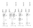
- FIG. 5which includes FIGS. 5A through 5D , illustrates different types of wind turbine-based generators included in clusters of renewable power generators.
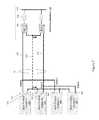
- FIG. 6illustrates a block diagram of another embodiment of a renewable power generation system that includes clusters of renewable power generators and a DC connection system that connects the clusters to a power grid substation.
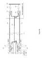
- FIG. 7illustrates a block diagram of yet another embodiment of a renewable power generation system that includes clusters of renewable power generators and a DC connection system that connects the clusters to a power grid substation.
- FIG. 8which includes FIGS. 8A and 8B , illustrates a block diagram of an embodiment of a DC connection system for connecting clusters of renewable power generators to a power grid substation with and without a neutral cable in service.
- a direct current (DC) connection systemfor connecting renewable power generators to a power grid substation.
- the DC connection systemhas positive and negative monopole collection networks for connecting to different clusters of renewable power generators.
- Each cluster of renewable power generatorsprovides either positive-valued or negative-valued unipolar DC output.
- the DC connection systemalso has a bipole transmission system for connecting the monopole collection networks to a power grid substation e.g. without using a power converter to connect the monopole DC collection networks to the bipole transmission system.
- the DC connection systemprovides a DC connection scheme for integrating a plurality of wind turbines grouped into at least two wind turbine clusters.
- the wind turbines in the first clusterprovide positive-valued DC outputs and are connected to a positive monopole DC collection network of the DC connection system.
- the wind turbines in the second clusterprovide negative-valued DC outputs and are connected to a negative monopole dc collection network of the DC connection system.
- the neutral terminals of the two clustersare connected, resulting in an aggregated wind energy source with bipolar DC output.
- the aggregated wind energy sourceis interconnected to an onshore power grid substation through the bipole transmission system which comprises a positive pole cable, a negative pole cable and an optional neutral cable.
- Such a systemallows for the direct connection (i.e. without an intermediary power converter) of the wind turbines or other renewable power generators to the main power grid, thereby eliminating the need for an offshore platform.
- FIG. 1illustrates an embodiment of a renewable power generation system that includes a first cluster 100 of renewable power generators configured to provide positive-valued DC voltage outputs, a second cluster 102 of renewable power generators configured to provide negative-valued DC voltage outputs and a DC connection system for connecting the clusters 100 , 102 of renewable power generators to a power grid substation 104 which can include converters 106 , transformers 108 , buses 110 , etc.
- the renewable power generatorsare wind turbines as indicated in FIG. 1 .
- Other types of renewable power generatorssuch as solar, geothermal, water, tidal, etc. can be included in the clusters 100 , 102 instead of or in addition to wind turbines.
- the DC connection systemincludes a positive monopole DC collection network 112 , a negative monopole DC collection network 114 and a bipole transmission system 116 .
- the positive monopole DC collection network 112aggregates the positive-valued DC voltage outputs of the first cluster 100 of renewable power generators onto a positive terminal Udc(+) of the positive monopole DC collection network 112 .
- the negative monopole DC collection network 114aggregates the negative-valued DC voltage outputs of the second cluster 102 of renewable power generators onto a negative terminal Udc( ⁇ ) of the negative monopole DC collection network 114 .
- the neutral terminals of the renewable power generators included in each cluster 100 , 102are connected by a neutral cable 113 , 115 of the corresponding monopole DC collection network 112 , 114 .
- each monopole DC collection network 112 , 114can include one DC cable with a rated voltage, either positive-valued or negative-valued, and a neutral cable rated for only a few kilovolts.
- each monopole DC collection network 112 , 114can include one coaxial structured DC cable having an inner conductor with a rated voltage either positive-valued or negative-valued, and an outer return conductor for only a few kilovolts.
- Still other cable implementationscan be used for the positive and negative monopole DC collection networks 112 , 114 of the DC connection system.
- the bipole transmission system 116 of the DC connection systemcan be considered a ‘virtual’ bipole transmission system in that it is coupled to the positive and negative terminals Udc(+), Udc( ⁇ ) of the monopole DC collection networks 112 , 114 .
- the bipole transmission system 116is coupled to the positive and negative terminals Udc(+), Udc( ⁇ ) of the monopole DC collection networks 112 , 114 e.g. without using a power converter.
- the connectioncan be made through switchgear (not shown) but not through a power converter.
- the monopole DC collection networks 112 , 114can transfer power at the same or different voltage as described in more detail later herein.
- the bipole transmission system 116transfers the aggregated power to the power grid substation 104 at substantially the same voltage as the positive and negative monopole DC collection networks 112 , 114 in this example i.e. no power converter in the bipole transmission system 116 .
- the bipole transmission system 116includes two separate DC cables with rated voltage, one positive-valued and one negative-valued, and a neutral cable rated for only a few kilovolts.
- the bipole transmission system 116includes two separate DC cables with rated voltage, one positive-valued and one negative-valued, without a neutral cable for the installations where ground return currents are allowed.
- the bipole transmission system 116includes a single DC cable with three conductors, one positive pole conductor, one negative pole conductor and one neutral conductor. Still other cable implementations can be used for the bipole transmission system 116 of the DC connection system.
- the neutral terminals of the renewable generators in each cluster 100 , 102are connected, resulting in an aggregated wind energy source with bipolar DC output.
- the DC connection systemtransfers the aggregated power to the power grid substation 104 which provides an interface with the main power grid.
- the aggregated wind energy sourceis interconnected to an onshore converter station 104 through the bipole transmission system 116 which comprises a positive pole cable or line 118 , a negative pole cable or line 120 and an optional neutral cable or line 122 (also commonly referred to as metallic return cable).
- the neutral cable 122connects the neutral terminals Udc(+), Udc( ⁇ ) of the monopole DC collection networks 112 , 114 to the power grid substation 104 . This way, the positive monopole DC collection network 112 and the negative monopole DC collection network 114 can operate independently of one another if the neutral cable 122 is in service.
- FIG. 2illustrates an embodiment of a method of transferring power generated by the renewable power generation system to a power grid.
- the methodincludes configuring the first cluster 100 of renewable power generators to provide an aggregated positive-valued DC voltage output (Block 200 ), configuring the second cluster 102 of renewable power generators to provide an aggregated negative-valued DC voltage output (Block 210 ), connecting the aggregated positive-valued DC voltage output of the first cluster 100 to the power grid substation 104 via the positive monopole DC collection network 112 and the bipole transmission system 116 of the DC connection system (Block 220 ), and connecting the aggregated negative-value DC voltage output of the second cluster 102 of renewable power generators to the power grid substation 104 via the negative second monopole DC collection network 114 and the bipole transmission system 116 of the DC connection system (Block 230 ).
- the positive monopole DC collection network 112collects the power produced by the first cluster 100 of renewable power generators at a voltage range from about +20 kV to about +100 kV referenced to ground potential.
- the negative monopole DC collection network 114collects power produced by the second cluster 102 of renewable power generators at a voltage range from about ⁇ 20 kV to about ⁇ 100 kV referenced to ground potential.
- the positive and negative monopole DC collection networks 112 , 114can collect power at substantially the same voltage range.
- the positive monopole DC collection network 112collects power produced by the first cluster 100 of renewable power generators at different voltage range from which the negative monopole DC collection network 114 collects power produced by the second cluster 102 of renewable power generators.
- the bipole transmission system 116transfers the aggregated power to the power grid substation 104 at a positive voltage between about +20 kV to about +100 kV referenced to ground potential and at a negative voltage between about ⁇ 20 kV to about ⁇ 100 kV referenced to ground potential according to an embodiment.
- the level of the positive DC voltage aggregated onto the positive terminal Udc(+) of the positive monopole DC collection network 112 and the level of the negative DC voltage aggregated onto the negative terminal Udc( ⁇ ) of the negative monopole DC collection network 114depends on the coupling configuration within the respective clusters 100 , 102 of renewable power generators.
- FIG. 3illustrates one configuration embodiment for the positive and negative DC collection networks 112 , 114 of the DC connection system.
- the positive monopole DC collection network 112aggregates the positive-valued (+) DC voltage outputs of the first cluster 100 of renewable power generators onto the positive terminal Udc(+) of the positive monopole DC collection network 112 .
- the negative monopole DC collection network 114similarly aggregates the negative-valued ( ⁇ ) DC voltage outputs of the second cluster 102 of renewable power generators onto the negative terminal Udc( ⁇ ) of the negative monopole DC collection network 114 .
- the renewable power generatorsare shown as wind turbines 300 each of which includes a rotor 302 for extracting energy from a fluid flow and converting the extracted energy into mechanical energy, an electric generator (G) 304 for converting the mechanical energy into AC electrical energy, a step-up transformer 306 for transferring the AC electrical energy at a lower voltage to a higher voltage, and a converter 308 for converting the AC electrical energy at the higher voltage to DC electrical energy.
- Gelectric generator
- step-up transformer 306for transferring the AC electrical energy at a lower voltage to a higher voltage
- converter 308for converting the AC electrical energy at the higher voltage to DC electrical energy.
- other types of renewable power generatorscan be used such as solar, geothermal, water, tidal, etc.
- each cluster 100 , 102are connected by the respective neutral cable 113 , 115 of the corresponding monopole DC collection network 112 , 114 .
- the renewable power generators in the first cluster 100provide positive-valued DC outputs and the renewable power generators 102 in the second cluster provide negative-valued DC outputs.
- the renewable power generators producing positive-value DC outputsare connected in parallel to the positive monopole DC collection network 112 .
- the renewable power generators producing negative-value DC outputsare connected in parallel to the negative monopole dc collection network 114 .
- FIG. 4illustrates another configuration embodiment for the positive and negative DC collection networks 112 , 114 of the DC connection system.
- the embodiment shown in FIG. 4is similar to the embodiment shown in FIG. 3 .
- the renewable power generators producing positive-value (+) DC outputsare connected in series to the positive monopole DC collection network 112 and the renewable power generators producing negative-value ( ⁇ ) DC outputs are connected in series to the negative monopole dc collection network 114 .
- any series/parallel connection configuration for the renewable power generatorscan be utilized in order to realize the desired DC output voltage and current ranges.
- each wind turbine 300preferably generates a high enough DC output as technically and economically practicable.
- a wind turbine-based generation systeme.g. as shown in FIGS. 3 and 4 , comprises a turbine 302 , an electric generator 304 , a step-up transformer 306 , and a converter 308 as previously described herein.
- FIG. 5which includes FIGS. 5A through 5D , shows alternative wind turbine-based generation systems with unipolar DC output.
- the wind turbine-based generation systemincludes a wind turbine generator 304 with low or medium voltage variable frequency output, a two-winding transformer 306 to increase the voltage and a converter/rectifier 308 to convert the variable frequency output into unipolar DC output.
- the wind turbine-based generation systemincludes a wind turbine generator 304 with low or medium voltage variable frequency output, a three-winding transformer 306 to increase the voltage and two series connected converters/rectifiers 308 to convert the variable frequency output into unipolar DC output.
- FIG. 5shows alternative wind turbine-based generation systems with unipolar DC output.
- the wind turbine-based generation systemincludes a wind turbine generator 304 with low or medium voltage variable frequency output, a two-winding transformer 306 to increase the voltage and two series connected converters/rectifiers 308 to convert the variable frequency output into unipolar DC output.
- the wind turbine-based generation systemincludes a wind turbine generator 304 with low or medium voltage variable frequency output, a converter/rectifier 308 to convert the variable frequency output into unipolar DC output and a DC/DC converter 310 to increase the DC output voltage.
- the wind turbine-based generation systemincludes a wind turbine generator 304 with higher voltage variable frequency output and a converter/rectifier 308 to converter the variable frequency output into unipolar DC output.
- Still other types of wind turbine-based generation systems with unipolar DC outputcan be coupled to the DC collection system via the positive and negative monopole DC collection networks.
- the basic configuration of the DC connection system shown in FIG. 1can be extended and modified depending on overall system design optimization considerations.
- FIG. 6illustrates one embodiment where the renewable power generators e.g. in an offshore wind farm are grouped into four clusters 100 , 102 , 400 , 402 and connected to the main power grid using two parallel bipole transmission systems 116 , 404 .
- the DC connection systemfurther includes an additional positive monopole DC collection network 406 for aggregating positive-valued DC voltage outputs of a third cluster 400 of renewable power generators onto a positive terminal Udc(+) of an additional positive monopole DC collection network 406 .
- the DC connection systemalso includes an additional negative monopole DC collection network 408 for aggregating negative-valued DC voltage outputs of a fourth cluster 402 of renewable power generators onto a negative terminal Udc( ⁇ ) of the additional negative monopole DC collection network 408 .
- the neutral terminals of all four clusters 100 , 102 , 400 , 402are connected, resulting in an aggregated wind energy source with bipolar DC output as previously described herein.
- the DC connection systemincludes a second bipole transmission system 404 coupled to the positive and negative terminals of the additional monopole DC collection networks 406 , 408 e.g. without using a power converter.
- the second bipole transmission system 404comprises a positive pole cable or line 410 and a negative pole cable or line 412 .
- the neutral connectionscan be aggregated onto the neutral cable 122 of the first bipole transmission system 116 .
- the bipole transmission systems 116 , 404transfer the aggregated power to the power grid substation 104 .
- FIG. 7illustrates another embodiment where the renewable power generators e.g. in an offshore wind farm are grouped into four clusters 100 , 102 , 400 , 402 and connected to the main power grid using a single bipole transmission system 116 .
- an additional positive monopole DC collection network 406aggregates positive-valued DC voltage outputs of a third cluster 400 of renewable power generators onto a positive terminal Udc(+) of the additional positive monopole DC collection network 406 .
- An additional negative monopole DC collection network 408aggregates negative-valued DC voltage outputs of a fourth cluster 402 of renewable power generators onto a negative terminal Udc( ⁇ ) of the additional negative monopole DC collection network 408 .
- the DC collection systemdoes not include a second bipole transmission system. Instead a single bipole transmission system 116 is coupled to the positive and negative terminals of the additional monopole DC collection networks e.g. without using a power converter, for transferring the aggregated power to the power grid substation 104 .
- the DC connection system connecting the aggregated renewable energy source with bipole DC output to a power grid substation 104comprises at least two DC cables, a positive pole cable 118 and a negative pole cable 120 .
- a third neutral cable 122can be optionally provided for such a virtual bipole connection system.
- the power outputs of the clusters 100 , 102 , 400 , 402 of renewable power generatorsare not equal most of the time even under normal operating conditions, and the ground return currents may be strictly restrained for many installations.
- FIG. 8Ashows the DC collection system of FIG. 1 with the neutral cable 122 in service, where the neutral terminals of the clusters 100 , 102 of renewable power generators are connected to the power grid substation 104 via the respective neutral cable 113 , 115 of the corresponding monopole DC collection network 112 , 114 and the neutral cable 122 of the bipole transmission system 116 .
- Monopole operation of the DC connection systemis possible under certain component outages or scheduled maintenance with the neutral cable 122 in service.
- the positive monopole operation modeallows the renewable power generators in the positive pole cluster 100 to power the power grid substation 104 during an outage of a major negative pole component such as the negative pole transmission cable, negative pole collection network, negative pole converter at the power grid substation, or a combined outage of several negative pole components.
- a major negative pole componentsuch as the negative pole transmission cable, negative pole collection network, negative pole converter at the power grid substation, or a combined outage of several negative pole components.
- the operation of the positive monopole network 112 and the negative monopole network 114are independent of each other with the neutral cable 122 in service.
- the positive and negative monopole networks 112 , 114are nominally rated for the same voltage, at a given instant they may operate at different voltage levels.
- a remotely-controlled switching mechanism 500 associated with the connection of the neutral terminals of the positive pole and the negative pole clusters 100 , 102 and the terminals of the neutral cable 122can be provided.
- the remotely-controlled switching mechanism 500reconfigures the connection circuits and grounding scheme based on system operation requirements, maintenance and repairing needs, including connecting or disconnecting the neutral transmission cable 122 from the system, connecting or disconnecting one cluster neutral cable 113 / 115 from the system, and connecting or disconnecting the groundings of the neutral transmission cable 122 and the groundings of cluster neutral cables 113 , 115 .
- FIG. 8Bshows the DC collection system with the neutral cable 122 out of service e.g. responsive to action taken by the remotely-controlled switching mechanism 500 .
- the DC connection systemcan still operate with the neutral cable 122 out of service, by planning for scheduled maintenance or due to possible failure of the neutral cable 122 .
- the cluster 100 / 102 of renewable power generators that is generating the most powermay be required to reduce its power output so that the amount of current flowing through the grounded connection 502 of the bipole transmission system 116 is limited during the neutral cable outage.
- a real-time dispatch functionis implemented e.g. in a plant energy management system (EMS).
- EMSplant energy management system
- the real-time dispatch functionbalances the power outputs from the two clusters 100 , 102 of renewable power generators, thus controlling the ground return currents within the allowed levels.
- standard real-time wind speed predictioncan be used to estimate with reasonable accuracy the look-ahead power output of the wind turbine clusters 100 , 102 .
- the real-time dispatch functionthen reduces the power output from the wind turbine cluster 100 / 102 that produces more power than the other cluster 102 / 100 .
- the real-time dispatch functionneeds only to be activated when the neutral cable 122 is out of service. If the rated power outputs of the operating wind turbines are equal or close, the unbalanced power outputs of the two clusters 100 , 102 should be insignificant under most operating conditions.
- the real-time dispatch functionreduces the power output from selected wind turbines and can even turn-off one or more wind turbines in the cluster 100 / 102 that produces more power than the other cluster 102 / 100 .
Landscapes
- Engineering & Computer Science (AREA)
- Power Engineering (AREA)
- Supply And Distribution Of Alternating Current (AREA)
- Direct Current Feeding And Distribution (AREA)
Abstract
Description
Claims (24)
Priority Applications (2)
| Application Number | Priority Date | Filing Date | Title |
|---|---|---|---|
| US14/448,294US9800054B2 (en) | 2014-07-31 | 2014-07-31 | DC connection system for renewable power generators |
| PCT/US2015/042184WO2016018783A1 (en) | 2014-07-31 | 2015-07-27 | Dc connection system for renewable power generators |
Applications Claiming Priority (1)
| Application Number | Priority Date | Filing Date | Title |
|---|---|---|---|
| US14/448,294US9800054B2 (en) | 2014-07-31 | 2014-07-31 | DC connection system for renewable power generators |
Publications (2)
| Publication Number | Publication Date |
|---|---|
| US20160036221A1 US20160036221A1 (en) | 2016-02-04 |
| US9800054B2true US9800054B2 (en) | 2017-10-24 |
Family
ID=53785755
Family Applications (1)
| Application Number | Title | Priority Date | Filing Date |
|---|---|---|---|
| US14/448,294Active2035-12-23US9800054B2 (en) | 2014-07-31 | 2014-07-31 | DC connection system for renewable power generators |
Country Status (2)
| Country | Link |
|---|---|
| US (1) | US9800054B2 (en) |
| WO (1) | WO2016018783A1 (en) |
Families Citing this family (14)
| Publication number | Priority date | Publication date | Assignee | Title |
|---|---|---|---|---|
| US10587121B2 (en)* | 2017-05-23 | 2020-03-10 | General Electric Company | Electrical power systems and subsystems |
| FR3067179B1 (en)* | 2017-06-06 | 2020-10-09 | Stx France Sa | ELECTRICAL SUB-STATION, INSTALLATION AND IMPLEMENTATION PROCEDURE |
| CN107565590B (en)* | 2017-09-06 | 2020-05-05 | 合肥工业大学 | Hybrid high-voltage direct-current power transmission system suitable for wind power transmission |
| CN108832649B (en)* | 2018-06-05 | 2021-08-27 | 天津大学 | Operating point optimization-based true bipolar flexible direct-current power grid coordination control method |
| CN109344875B (en)* | 2018-08-31 | 2020-11-20 | 中国南方电网有限责任公司电网技术研究中心 | Method and device for generating time series of daily wind power output based on cluster analysis |
| CN111342498A (en)* | 2020-03-16 | 2020-06-26 | 株洲中车时代电气股份有限公司 | Maximum demand control system and method for railway traction substation |
| WO2021208045A1 (en)* | 2020-04-16 | 2021-10-21 | 华为技术有限公司 | Power supply system |
| CN112421602B (en)* | 2020-11-11 | 2023-09-01 | 上海交通大学 | DC transformer with true bipolar off-grid operation capability and control method |
| EP4060083A1 (en)* | 2021-03-18 | 2022-09-21 | Siemens Energy Global GmbH & Co. KG | Electrolysis unit, system and method |
| WO2022204975A1 (en)* | 2021-03-30 | 2022-10-06 | 华为数字能源技术有限公司 | Bipolar power supply system and control method |
| CN113489043A (en)* | 2021-07-12 | 2021-10-08 | 南方电网科学研究院有限责任公司 | Parallel multi-terminal direct current system |
| US12051906B2 (en)* | 2022-03-02 | 2024-07-30 | National Technology & Engineering Solutions Of Sandia, Llc | Wind turbine power phase control with DC collection bus for onshore/offshore windfarms |
| WO2024078702A1 (en)* | 2022-10-11 | 2024-04-18 | Huawei Digital Power Technologies Co., Ltd. | Combined split photovoltaic architecture |
| WO2024260568A1 (en)* | 2023-06-23 | 2024-12-26 | Ge Energy Power Conversion Technology Limited | Dc power transmission system, and associated subsea dc power transmission system and method |
Citations (26)
| Publication number | Priority date | Publication date | Assignee | Title |
|---|---|---|---|---|
| DE19620906A1 (en) | 1996-05-24 | 1998-01-08 | Siemens Ag | Wind farm |
| WO2000074198A1 (en) | 1999-05-28 | 2000-12-07 | Abb Ab | A wind power plant |
| US20020079706A1 (en) | 2000-05-23 | 2002-06-27 | Rebsdorf Anders V. | Variable speed wind turbine having a matrix converter |
| US7324359B2 (en) | 2004-01-09 | 2008-01-29 | Semikron Elektronik Gmbh & Co., Kg | Circuit for converting alternating voltage into high-voltage direct voltage |
| US20080143111A1 (en) | 2006-12-14 | 2008-06-19 | Masaya Ichinose | Wind Power Generation System |
| WO2009135728A2 (en) | 2008-05-07 | 2009-11-12 | Siemens Aktiengesellschaft | Wind farm comprising a plurality of wind power plants |
| US20090283130A1 (en)* | 2007-08-03 | 2009-11-19 | Advanced Energy Industries, Inc. | System, method, and apparatus for remotely coupling photovoltaic arrays |
| US20100133901A1 (en) | 2008-12-03 | 2010-06-03 | General Electric Company | Modular stacked subsea power system architectures |
| WO2011055175A1 (en) | 2009-11-03 | 2011-05-12 | Trevi Energy S.P.A. | A control system for wind farms with aerogenerators provided with dc modular converters |
| US20110141773A1 (en) | 2010-08-05 | 2011-06-16 | General Electric Company | Hvdc connection of wind turbine |
| EP2341594A1 (en) | 2009-12-29 | 2011-07-06 | Converteam Technology Ltd | Power collection and transmission systems |
| DE102010023019A1 (en) | 2010-06-08 | 2011-12-08 | Siemens Aktiengesellschaft | Wave generator system |
| EP2408081A1 (en) | 2010-07-16 | 2012-01-18 | ABB Technology AG | Modular multi-level converter |
| US8129853B2 (en) | 2009-06-30 | 2012-03-06 | Teco-Westinghouse Motor Company | Power converter for use with wind generator |
| WO2012041380A1 (en) | 2010-09-30 | 2012-04-05 | Alstom Grid Uk Limited | Modular converter with reduced protection requirements that prevents damage to components by extinguishing fault currents. |
| WO2012048743A1 (en) | 2010-10-13 | 2012-04-19 | Abb Schweiz Ag | Current-transmitting device for a wind power plant |
| US8174138B2 (en) | 2008-04-30 | 2012-05-08 | Trevi Energy S.P.A. | Modular converter for converting the electric power produced by aerogenerators, and wind-power plant that uses said converter |
| US20120175962A1 (en)* | 2011-01-11 | 2012-07-12 | Converteam Technology Ltd. | Power Collection and Transmission Systems |
| US8263276B1 (en) | 2008-07-08 | 2012-09-11 | Bloom Energy Corporation | Startup power control in a fuel cell system |
| US20130197704A1 (en) | 2012-02-01 | 2013-08-01 | Abb Research Ltd | Dc connection scheme for windfarm with internal mvdc collection grid |
| WO2013110327A1 (en) | 2012-01-25 | 2013-08-01 | Abb Research Ltd | Wind park with real time wind speed measurements |
| US8503202B2 (en) | 2009-03-11 | 2013-08-06 | Abb Technology Ag | Modular voltage source converter |
| US20130200714A1 (en) | 2012-02-02 | 2013-08-08 | Abb Research Ltd | Medium voltage dc collection system |
| US8552577B2 (en) | 2011-09-07 | 2013-10-08 | Delta Electronics (Shanghai) Co., Ltd. | Wind-power generation system with over-speed protection and method of operating the same |
| US20130322131A1 (en) | 2010-12-09 | 2013-12-05 | State Grid Corporation Of China | Cascaded converter station and cascaded multi-terminal hvdc power transmission system |
| US20140197639A1 (en) | 2013-01-14 | 2014-07-17 | Abb Technology Ag | Turbine-Based Energy Generation System With DC Output |
- 2014
- 2014-07-31USUS14/448,294patent/US9800054B2/enactiveActive
- 2015
- 2015-07-27WOPCT/US2015/042184patent/WO2016018783A1/enactiveApplication Filing
Patent Citations (29)
| Publication number | Priority date | Publication date | Assignee | Title |
|---|---|---|---|---|
| DE19620906A1 (en) | 1996-05-24 | 1998-01-08 | Siemens Ag | Wind farm |
| WO2000074198A1 (en) | 1999-05-28 | 2000-12-07 | Abb Ab | A wind power plant |
| US20020079706A1 (en) | 2000-05-23 | 2002-06-27 | Rebsdorf Anders V. | Variable speed wind turbine having a matrix converter |
| US7324359B2 (en) | 2004-01-09 | 2008-01-29 | Semikron Elektronik Gmbh & Co., Kg | Circuit for converting alternating voltage into high-voltage direct voltage |
| US20080143111A1 (en) | 2006-12-14 | 2008-06-19 | Masaya Ichinose | Wind Power Generation System |
| US20090283130A1 (en)* | 2007-08-03 | 2009-11-19 | Advanced Energy Industries, Inc. | System, method, and apparatus for remotely coupling photovoltaic arrays |
| US8174138B2 (en) | 2008-04-30 | 2012-05-08 | Trevi Energy S.P.A. | Modular converter for converting the electric power produced by aerogenerators, and wind-power plant that uses said converter |
| WO2009135728A2 (en) | 2008-05-07 | 2009-11-12 | Siemens Aktiengesellschaft | Wind farm comprising a plurality of wind power plants |
| WO2009135728A3 (en) | 2008-05-07 | 2010-06-10 | Siemens Aktiengesellschaft | Wind power plant and wind farm comprising a plurality of wind power plants |
| US20110049994A1 (en) | 2008-05-07 | 2011-03-03 | Siemens Aktiengesellschaft | Wind farm having a plurality of wind energy installations |
| US8263276B1 (en) | 2008-07-08 | 2012-09-11 | Bloom Energy Corporation | Startup power control in a fuel cell system |
| US20100133901A1 (en) | 2008-12-03 | 2010-06-03 | General Electric Company | Modular stacked subsea power system architectures |
| US8503202B2 (en) | 2009-03-11 | 2013-08-06 | Abb Technology Ag | Modular voltage source converter |
| US8129853B2 (en) | 2009-06-30 | 2012-03-06 | Teco-Westinghouse Motor Company | Power converter for use with wind generator |
| WO2011055175A1 (en) | 2009-11-03 | 2011-05-12 | Trevi Energy S.P.A. | A control system for wind farms with aerogenerators provided with dc modular converters |
| EP2341594A1 (en) | 2009-12-29 | 2011-07-06 | Converteam Technology Ltd | Power collection and transmission systems |
| DE102010023019A1 (en) | 2010-06-08 | 2011-12-08 | Siemens Aktiengesellschaft | Wave generator system |
| EP2408081A1 (en) | 2010-07-16 | 2012-01-18 | ABB Technology AG | Modular multi-level converter |
| US20110141773A1 (en) | 2010-08-05 | 2011-06-16 | General Electric Company | Hvdc connection of wind turbine |
| US8018083B2 (en) | 2010-08-05 | 2011-09-13 | General Electric Company | HVDC connection of wind turbine |
| WO2012041380A1 (en) | 2010-09-30 | 2012-04-05 | Alstom Grid Uk Limited | Modular converter with reduced protection requirements that prevents damage to components by extinguishing fault currents. |
| WO2012048743A1 (en) | 2010-10-13 | 2012-04-19 | Abb Schweiz Ag | Current-transmitting device for a wind power plant |
| US20130322131A1 (en) | 2010-12-09 | 2013-12-05 | State Grid Corporation Of China | Cascaded converter station and cascaded multi-terminal hvdc power transmission system |
| US20120175962A1 (en)* | 2011-01-11 | 2012-07-12 | Converteam Technology Ltd. | Power Collection and Transmission Systems |
| US8552577B2 (en) | 2011-09-07 | 2013-10-08 | Delta Electronics (Shanghai) Co., Ltd. | Wind-power generation system with over-speed protection and method of operating the same |
| WO2013110327A1 (en) | 2012-01-25 | 2013-08-01 | Abb Research Ltd | Wind park with real time wind speed measurements |
| US20130197704A1 (en) | 2012-02-01 | 2013-08-01 | Abb Research Ltd | Dc connection scheme for windfarm with internal mvdc collection grid |
| US20130200714A1 (en) | 2012-02-02 | 2013-08-08 | Abb Research Ltd | Medium voltage dc collection system |
| US20140197639A1 (en) | 2013-01-14 | 2014-07-17 | Abb Technology Ag | Turbine-Based Energy Generation System With DC Output |
Non-Patent Citations (27)
| Title |
|---|
| Baroudi, et al., "A Review of Power Converter Topologies for Wind Generators", IEEE, 2005, Department of Electrical and Computer Engineering, University of Alberta, pp. 458-465. |
| Chen, et al., "DC/DC Conversion Systems Consisting of Multiple Converter Modules: Stability, Control, and Experimental Verifications", IEEE Transactions on Power Electronics, vol. 24, No. 6, Jun. 6, 2009, pp. 1463-1474. |
| Garcia, et al., "Modeling and Control of Squirrel Cage Induction Generator with Full Power Converter Applied to Windmills", Oulun Yliopisto, University of Oulu, Nov. 30, 2009, pp. 1-86. |
| Johnson, Brian K. , "Current Control on a Superconducting High Voltage DC Mesh", University of Wisconsin-Madison, May 1989, pp. 1-91. |
| Lena, Max et al., "Energy Evaluation for DC/DC Converters in DC-Based Wind Farms", Division of Electric Power Engineering, Department of Energy and Environment, Chalmers University of Technology, Goteborg, Sweden, 2007, pp. 1-161. |
| Liserre, et al., "Overview of Multi-MW Wind Turbines and Wind Parks", IEEE Transactions on Industrial Electronics, vol. 58, No. 4, Apr. 4, 2011, pp. 1081-1095. |
| Lopatkin, et al., "High-Voltage Bi-Directional DC-DC-Converter for Advanced Electric Locomotives", Power Electronics and Applications, 2009, EPE '09, 13th European Conference, Sep. 8-10, 2009, pp. 1-10. |
| Lundberg, Stefan , "Evaluation of Wind Farm Layouts", Department of Electrical Power Engineering, Chalmers University of Technology, Goteborg, Sweden, pp. 1-8. |
| Lundberg, Stefan , "Wind Farm Configuration and Energy Efficient Studies—Series DC Versus AC layouts", Department of Energy and Environment, Chalmers University of Technology, Goteborg, Sweden 2006, ISBN 978-91-7291-884-9, pp. 1-141. |
| Macken, et al., "A DC Bus System for Connecting Offshore Wind Turbines with the Utility System", Katholieke Universiteit Leuven, Department of Electrical Engineering, Leuven, Belgium, pp. 1-6. |
| Max, et al., "Control Method and Snubber Selection for a 5 MW Wind Turbine Single Active Bridge DC/DC Converter", Chalmers University of Technology, Division of Energy and Environment, Goteborg, Sweden, pp. 1-10. |
| Max, Lena , "Design and Control of a DC Collection Grid for a Wind Farm", Department of Energy and Environment, Chalmers University of Technology, Goteborg, Sweden, 2009, pp. 1-167. |
| Meier, et al., "Benchmark of Annual Energy Production for Different Wind Farm Topologies", IEEE, 2005, Royal Institute of Technology, Electrical Machines and Power Electronics, Stockholm, Sweden, Vestas Wind Systems A/S R&D Converter Design, Hammel, Danmark, pp. 2073-2080. |
| Meier, et al., "New Topology for More Efficient AC/DC Converters for Future Offshore Wind Farms", Royal Institute of Technology, Stockholm, Sweden, pp. 1-6. |
| Meier, et al., "New Voltage Source Converter Topology for HVDC Grid Connection of Offshore Wind Farms", Proceedings of EPE-PEMC, Sep. 2004, Latvia, pp. 1-8. |
| Meyer, et al., "Key Components for Future Offshore DC Grids", Aachener Beitrage des ISEA, vol. 46, Sep. 2007, Institute for Power Electronics and Electrical Drives, RWTH Aachen University, pp. 1-98. |
| Mogstad, et al., "A Power Conversion System for Offshore Wind Parks", IEEE, Norwegian University of Science and Technology, Department of Electric Power Engineering, Trondheim, Norway, pp. 2106-2112. |
| Mogstad, et al., "Power Collection and Integration on the Electric Grid from Offshore Wind Parks", NORPIE, Nordic Workshop on Power and Industrial Electronics, Norweigan University of Science and Technology, Department of Electric Power Engineering, Trondheim , Norway, Jun. 9-11, 2008, pp. 1-8. |
| Norpie, , "4th Nordic Workshop on Power and Industrial Electronics", NTNU, Norweigan University of Science and Technology, Department of Electrical Power Engineering, Jun. 14-16, 2014, pp. 1-7. |
| Oates, Colin , "A Methodology for Developing ‘Chainlink’ Converters", Areva T&D Pes, pp. 1-10. |
| Pan, et al., "DC Connection for Large-Scale Wind Farms", ABB Research Corp., pp. 1-7. |
| Prasai, et al., "A New Architecture for Offshore Wind Farms", IEEE Transactions on Power Electronics, vol. 23, No. 3, May 2008, pp. 1198-1204. |
| Ranganathan, et al., "A Regulated DC-DC Voltage Source Converter Using a High Frequency Link", IEEE Transactions on Industry Applications, vol. 1A-18, No. 3, May/Jun. 1982, pp. 279-287. |
| Steimer, et al., "Medium Voltage Power Conversion Technology for Efficient Windpark Power Collection Grids", 2010 2nd IEEE International Symposium on Power Electronics for Distributed Generation Systems, pp. 12-18. |
| Takei, et al., "The Reverse Blocking IGBT for Matrix Converter with Ultra-Thin Wafer Technology", Fuji Electric Corporate Research and Development, Ltd., Japan, pp. 1-4. |
| Yuan, Xibo, "Low Voltage Ride Through Control of a Cascaded High Power Converter for Direct-Drive Permanent Magnet Wind Generators", IEEE, 2012, Department of Electrical and Electronic Engineering, The University of Bristol, Brisol, UK, pp. 3553-3559. |
| Zinov'Ev, et al., "High-Voltage DC-DC Converter for New-Generation Electric Locomotives", ISSN 1068-3712, Russian Electrical Engineering, 2009, vol. 80, No. 12, Allerton Press, Inc., pp. 685-690. |
Also Published As
| Publication number | Publication date |
|---|---|
| WO2016018783A1 (en) | 2016-02-04 |
| US20160036221A1 (en) | 2016-02-04 |
Similar Documents
| Publication | Publication Date | Title |
|---|---|---|
| US9800054B2 (en) | DC connection system for renewable power generators | |
| Musasa et al. | Review on DC collection grids for offshore wind farms with high‐voltage DC transmission system | |
| Deng et al. | Operation and control of a DC-grid offshore wind farm under DC transmission system faults | |
| Kirby et al. | HVDC transmission for large offshore windfarms | |
| Gil et al. | Feasibility analysis of offshore wind power plants with DC collection grid | |
| Bahirat et al. | Comparison of wind farm topologies for offshore applications | |
| US9525284B2 (en) | Medium voltage DC collection system with power electronics | |
| US9048694B2 (en) | DC connection scheme for windfarm with internal MVDC collection grid | |
| EP2478608B1 (en) | A power collection and distribution system | |
| US20180097450A1 (en) | Hybrid high voltage direct current converter station and operation method therefor | |
| Alagab et al. | Review of wind farm power collection schemes | |
| Das et al. | HVDC light for large offshore wind farm integration | |
| Pan et al. | Platformless DC collection and transmission for offshore wind | |
| MacLeod et al. | Connection of renewable energy sources through grid constraint points using HVDC power transmission systems | |
| KR20120095248A (en) | Power collection and transmission systems | |
| Wei et al. | Overview of offshore wind farm configurations | |
| CN113783217A (en) | Flexible direct current transmission system | |
| CN117879031A (en) | Method and device for constructing hybrid direct current power grid system based on far-sea wind power plant group | |
| CN216056352U (en) | Flexible direct current transmission system | |
| Elgeziry et al. | Integration enhancement of grid-connected wind farms using HVDC systems: Egyptian network case study | |
| Raval et al. | Comparison of energy production cost for MVAC and MVDC offshore wind farm distribution system | |
| Shehu et al. | Optimization of string size in a large DC windfarm | |
| Kervyn et al. | Future offshore wind farm electrical networks: a comparative framework | |
| Robinson et al. | VSC HVDC transmission and offshore grid design for a linear generator based wave farm | |
| Wu | Power system analysis of an offshore wind farm based on different layouts |
Legal Events
| Date | Code | Title | Description |
|---|---|---|---|
| AS | Assignment | Owner name:ABB TECHNOLOGY AG, SWITZERLAND Free format text:ASSIGNMENT OF ASSIGNORS INTEREST;ASSIGNORS:PAN, JIUPING;BALA, SANDEEP;REEL/FRAME:033436/0343 Effective date:20140729 | |
| AS | Assignment | Owner name:ABB SCHWEIZ AG, SWITZERLAND Free format text:MERGER;ASSIGNOR:ABB TECHNOLOGY LTD.;REEL/FRAME:040621/0929 Effective date:20160509 | |
| AS | Assignment | Owner name:ABB SCHWEIZ AG, SWITZERLAND Free format text:MERGER;ASSIGNOR:ABB TECHNOLOGY AG;REEL/FRAME:043930/0763 Effective date:20160617 | |
| STCF | Information on status: patent grant | Free format text:PATENTED CASE | |
| AS | Assignment | Owner name:ABB POWER GRIDS SWITZERLAND AG, SWITZERLAND Free format text:ASSIGNMENT OF ASSIGNORS INTEREST;ASSIGNOR:ABB SCHWEIZ AG;REEL/FRAME:052916/0001 Effective date:20191025 | |
| MAFP | Maintenance fee payment | Free format text:PAYMENT OF MAINTENANCE FEE, 4TH YEAR, LARGE ENTITY (ORIGINAL EVENT CODE: M1551); ENTITY STATUS OF PATENT OWNER: LARGE ENTITY Year of fee payment:4 | |
| AS | Assignment | Owner name:HITACHI ENERGY SWITZERLAND AG, SWITZERLAND Free format text:CHANGE OF NAME;ASSIGNOR:ABB POWER GRIDS SWITZERLAND AG;REEL/FRAME:058666/0540 Effective date:20211006 | |
| AS | Assignment | Owner name:ABB SCHWEIZ AG, SWITZERLAND Free format text:CORRECTIVE ASSIGNMENT TO CORRECT THE CONVEYING PARTY NAME PREVIOUSLY RECORDED AT REEL: 040621 FRAME: 0929. ASSIGNOR(S) HEREBY CONFIRMS THE MERGER;ASSIGNOR:ABB TECHNOLOGY AG;REEL/FRAME:060378/0488 Effective date:20160509 | |
| AS | Assignment | Owner name:HITACHI ENERGY LTD, SWITZERLAND Free format text:MERGER;ASSIGNOR:HITACHI ENERGY SWITZERLAND AG;REEL/FRAME:065549/0576 Effective date:20231002 | |
| MAFP | Maintenance fee payment | Free format text:PAYMENT OF MAINTENANCE FEE, 8TH YEAR, LARGE ENTITY (ORIGINAL EVENT CODE: M1552); ENTITY STATUS OF PATENT OWNER: LARGE ENTITY Year of fee payment:8 |