US9796280B2 - Systems and mobile application for electric wireless charging stations - Google Patents
Systems and mobile application for electric wireless charging stationsDownload PDFInfo
- Publication number
- US9796280B2 US9796280B2US13/849,904US201313849904AUS9796280B2US 9796280 B2US9796280 B2US 9796280B2US 201313849904 AUS201313849904 AUS 201313849904AUS 9796280 B2US9796280 B2US 9796280B2
- Authority
- US
- United States
- Prior art keywords
- charging
- charging unit
- vehicle
- receiver
- charging station
- Prior art date
- Legal status (The legal status is an assumption and is not a legal conclusion. Google has not performed a legal analysis and makes no representation as to the accuracy of the status listed.)
- Active - Reinstated, expires
Links
Images


Classifications
- B60L11/182—
- B—PERFORMING OPERATIONS; TRANSPORTING
- B60—VEHICLES IN GENERAL
- B60L—PROPULSION OF ELECTRICALLY-PROPELLED VEHICLES; SUPPLYING ELECTRIC POWER FOR AUXILIARY EQUIPMENT OF ELECTRICALLY-PROPELLED VEHICLES; ELECTRODYNAMIC BRAKE SYSTEMS FOR VEHICLES IN GENERAL; MAGNETIC SUSPENSION OR LEVITATION FOR VEHICLES; MONITORING OPERATING VARIABLES OF ELECTRICALLY-PROPELLED VEHICLES; ELECTRIC SAFETY DEVICES FOR ELECTRICALLY-PROPELLED VEHICLES
- B60L53/00—Methods of charging batteries, specially adapted for electric vehicles; Charging stations or on-board charging equipment therefor; Exchange of energy storage elements in electric vehicles
- B60L53/30—Constructional details of charging stations
- B60L53/305—Communication interfaces
- B60L11/1824—
- B60L11/1833—
- B60L11/1846—
- B60L11/1861—
- B—PERFORMING OPERATIONS; TRANSPORTING
- B60—VEHICLES IN GENERAL
- B60L—PROPULSION OF ELECTRICALLY-PROPELLED VEHICLES; SUPPLYING ELECTRIC POWER FOR AUXILIARY EQUIPMENT OF ELECTRICALLY-PROPELLED VEHICLES; ELECTRODYNAMIC BRAKE SYSTEMS FOR VEHICLES IN GENERAL; MAGNETIC SUSPENSION OR LEVITATION FOR VEHICLES; MONITORING OPERATING VARIABLES OF ELECTRICALLY-PROPELLED VEHICLES; ELECTRIC SAFETY DEVICES FOR ELECTRICALLY-PROPELLED VEHICLES
- B60L53/00—Methods of charging batteries, specially adapted for electric vehicles; Charging stations or on-board charging equipment therefor; Exchange of energy storage elements in electric vehicles
- B60L53/10—Methods of charging batteries, specially adapted for electric vehicles; Charging stations or on-board charging equipment therefor; Exchange of energy storage elements in electric vehicles characterised by the energy transfer between the charging station and the vehicle
- B60L53/12—Inductive energy transfer
- B—PERFORMING OPERATIONS; TRANSPORTING
- B60—VEHICLES IN GENERAL
- B60L—PROPULSION OF ELECTRICALLY-PROPELLED VEHICLES; SUPPLYING ELECTRIC POWER FOR AUXILIARY EQUIPMENT OF ELECTRICALLY-PROPELLED VEHICLES; ELECTRODYNAMIC BRAKE SYSTEMS FOR VEHICLES IN GENERAL; MAGNETIC SUSPENSION OR LEVITATION FOR VEHICLES; MONITORING OPERATING VARIABLES OF ELECTRICALLY-PROPELLED VEHICLES; ELECTRIC SAFETY DEVICES FOR ELECTRICALLY-PROPELLED VEHICLES
- B60L53/00—Methods of charging batteries, specially adapted for electric vehicles; Charging stations or on-board charging equipment therefor; Exchange of energy storage elements in electric vehicles
- B60L53/30—Constructional details of charging stations
- B60L53/35—Means for automatic or assisted adjustment of the relative position of charging devices and vehicles
- B60L53/36—Means for automatic or assisted adjustment of the relative position of charging devices and vehicles by positioning the vehicle
- B—PERFORMING OPERATIONS; TRANSPORTING
- B60—VEHICLES IN GENERAL
- B60L—PROPULSION OF ELECTRICALLY-PROPELLED VEHICLES; SUPPLYING ELECTRIC POWER FOR AUXILIARY EQUIPMENT OF ELECTRICALLY-PROPELLED VEHICLES; ELECTRODYNAMIC BRAKE SYSTEMS FOR VEHICLES IN GENERAL; MAGNETIC SUSPENSION OR LEVITATION FOR VEHICLES; MONITORING OPERATING VARIABLES OF ELECTRICALLY-PROPELLED VEHICLES; ELECTRIC SAFETY DEVICES FOR ELECTRICALLY-PROPELLED VEHICLES
- B60L53/00—Methods of charging batteries, specially adapted for electric vehicles; Charging stations or on-board charging equipment therefor; Exchange of energy storage elements in electric vehicles
- B60L53/60—Monitoring or controlling charging stations
- B60L53/65—Monitoring or controlling charging stations involving identification of vehicles or their battery types
- H—ELECTRICITY
- H02—GENERATION; CONVERSION OR DISTRIBUTION OF ELECTRIC POWER
- H02J—CIRCUIT ARRANGEMENTS OR SYSTEMS FOR SUPPLYING OR DISTRIBUTING ELECTRIC POWER; SYSTEMS FOR STORING ELECTRIC ENERGY
- H02J50/00—Circuit arrangements or systems for wireless supply or distribution of electric power
- H02J50/10—Circuit arrangements or systems for wireless supply or distribution of electric power using inductive coupling
- H02J50/12—Circuit arrangements or systems for wireless supply or distribution of electric power using inductive coupling of the resonant type
- H—ELECTRICITY
- H02—GENERATION; CONVERSION OR DISTRIBUTION OF ELECTRIC POWER
- H02J—CIRCUIT ARRANGEMENTS OR SYSTEMS FOR SUPPLYING OR DISTRIBUTING ELECTRIC POWER; SYSTEMS FOR STORING ELECTRIC ENERGY
- H02J50/00—Circuit arrangements or systems for wireless supply or distribution of electric power
- H02J50/60—Circuit arrangements or systems for wireless supply or distribution of electric power responsive to the presence of foreign objects, e.g. detection of living beings
- H—ELECTRICITY
- H02—GENERATION; CONVERSION OR DISTRIBUTION OF ELECTRIC POWER
- H02J—CIRCUIT ARRANGEMENTS OR SYSTEMS FOR SUPPLYING OR DISTRIBUTING ELECTRIC POWER; SYSTEMS FOR STORING ELECTRIC ENERGY
- H02J7/00—Circuit arrangements for charging or depolarising batteries or for supplying loads from batteries
- H02J7/02—Circuit arrangements for charging or depolarising batteries or for supplying loads from batteries for charging batteries from AC mains by converters
- B—PERFORMING OPERATIONS; TRANSPORTING
- B60—VEHICLES IN GENERAL
- B60L—PROPULSION OF ELECTRICALLY-PROPELLED VEHICLES; SUPPLYING ELECTRIC POWER FOR AUXILIARY EQUIPMENT OF ELECTRICALLY-PROPELLED VEHICLES; ELECTRODYNAMIC BRAKE SYSTEMS FOR VEHICLES IN GENERAL; MAGNETIC SUSPENSION OR LEVITATION FOR VEHICLES; MONITORING OPERATING VARIABLES OF ELECTRICALLY-PROPELLED VEHICLES; ELECTRIC SAFETY DEVICES FOR ELECTRICALLY-PROPELLED VEHICLES
- B60L2210/00—Converter types
- B60L2210/10—DC to DC converters
- B—PERFORMING OPERATIONS; TRANSPORTING
- B60—VEHICLES IN GENERAL
- B60L—PROPULSION OF ELECTRICALLY-PROPELLED VEHICLES; SUPPLYING ELECTRIC POWER FOR AUXILIARY EQUIPMENT OF ELECTRICALLY-PROPELLED VEHICLES; ELECTRODYNAMIC BRAKE SYSTEMS FOR VEHICLES IN GENERAL; MAGNETIC SUSPENSION OR LEVITATION FOR VEHICLES; MONITORING OPERATING VARIABLES OF ELECTRICALLY-PROPELLED VEHICLES; ELECTRIC SAFETY DEVICES FOR ELECTRICALLY-PROPELLED VEHICLES
- B60L2210/00—Converter types
- B60L2210/30—AC to DC converters
- B—PERFORMING OPERATIONS; TRANSPORTING
- B60—VEHICLES IN GENERAL
- B60L—PROPULSION OF ELECTRICALLY-PROPELLED VEHICLES; SUPPLYING ELECTRIC POWER FOR AUXILIARY EQUIPMENT OF ELECTRICALLY-PROPELLED VEHICLES; ELECTRODYNAMIC BRAKE SYSTEMS FOR VEHICLES IN GENERAL; MAGNETIC SUSPENSION OR LEVITATION FOR VEHICLES; MONITORING OPERATING VARIABLES OF ELECTRICALLY-PROPELLED VEHICLES; ELECTRIC SAFETY DEVICES FOR ELECTRICALLY-PROPELLED VEHICLES
- B60L2210/00—Converter types
- B60L2210/40—DC to AC converters
- B—PERFORMING OPERATIONS; TRANSPORTING
- B60—VEHICLES IN GENERAL
- B60L—PROPULSION OF ELECTRICALLY-PROPELLED VEHICLES; SUPPLYING ELECTRIC POWER FOR AUXILIARY EQUIPMENT OF ELECTRICALLY-PROPELLED VEHICLES; ELECTRODYNAMIC BRAKE SYSTEMS FOR VEHICLES IN GENERAL; MAGNETIC SUSPENSION OR LEVITATION FOR VEHICLES; MONITORING OPERATING VARIABLES OF ELECTRICALLY-PROPELLED VEHICLES; ELECTRIC SAFETY DEVICES FOR ELECTRICALLY-PROPELLED VEHICLES
- B60L2240/00—Control parameters of input or output; Target parameters
- B60L2240/40—Drive Train control parameters
- B60L2240/54—Drive Train control parameters related to batteries
- B60L2240/545—Temperature
- B—PERFORMING OPERATIONS; TRANSPORTING
- B60—VEHICLES IN GENERAL
- B60L—PROPULSION OF ELECTRICALLY-PROPELLED VEHICLES; SUPPLYING ELECTRIC POWER FOR AUXILIARY EQUIPMENT OF ELECTRICALLY-PROPELLED VEHICLES; ELECTRODYNAMIC BRAKE SYSTEMS FOR VEHICLES IN GENERAL; MAGNETIC SUSPENSION OR LEVITATION FOR VEHICLES; MONITORING OPERATING VARIABLES OF ELECTRICALLY-PROPELLED VEHICLES; ELECTRIC SAFETY DEVICES FOR ELECTRICALLY-PROPELLED VEHICLES
- B60L2240/00—Control parameters of input or output; Target parameters
- B60L2240/40—Drive Train control parameters
- B60L2240/54—Drive Train control parameters related to batteries
- B60L2240/547—Voltage
- B—PERFORMING OPERATIONS; TRANSPORTING
- B60—VEHICLES IN GENERAL
- B60L—PROPULSION OF ELECTRICALLY-PROPELLED VEHICLES; SUPPLYING ELECTRIC POWER FOR AUXILIARY EQUIPMENT OF ELECTRICALLY-PROPELLED VEHICLES; ELECTRODYNAMIC BRAKE SYSTEMS FOR VEHICLES IN GENERAL; MAGNETIC SUSPENSION OR LEVITATION FOR VEHICLES; MONITORING OPERATING VARIABLES OF ELECTRICALLY-PROPELLED VEHICLES; ELECTRIC SAFETY DEVICES FOR ELECTRICALLY-PROPELLED VEHICLES
- B60L2240/00—Control parameters of input or output; Target parameters
- B60L2240/40—Drive Train control parameters
- B60L2240/54—Drive Train control parameters related to batteries
- B60L2240/549—Current
- B—PERFORMING OPERATIONS; TRANSPORTING
- B60—VEHICLES IN GENERAL
- B60L—PROPULSION OF ELECTRICALLY-PROPELLED VEHICLES; SUPPLYING ELECTRIC POWER FOR AUXILIARY EQUIPMENT OF ELECTRICALLY-PROPELLED VEHICLES; ELECTRODYNAMIC BRAKE SYSTEMS FOR VEHICLES IN GENERAL; MAGNETIC SUSPENSION OR LEVITATION FOR VEHICLES; MONITORING OPERATING VARIABLES OF ELECTRICALLY-PROPELLED VEHICLES; ELECTRIC SAFETY DEVICES FOR ELECTRICALLY-PROPELLED VEHICLES
- B60L2240/00—Control parameters of input or output; Target parameters
- B60L2240/60—Navigation input
- B60L2240/62—Vehicle position
- B60L2240/622—Vehicle position by satellite navigation
- B—PERFORMING OPERATIONS; TRANSPORTING
- B60—VEHICLES IN GENERAL
- B60L—PROPULSION OF ELECTRICALLY-PROPELLED VEHICLES; SUPPLYING ELECTRIC POWER FOR AUXILIARY EQUIPMENT OF ELECTRICALLY-PROPELLED VEHICLES; ELECTRODYNAMIC BRAKE SYSTEMS FOR VEHICLES IN GENERAL; MAGNETIC SUSPENSION OR LEVITATION FOR VEHICLES; MONITORING OPERATING VARIABLES OF ELECTRICALLY-PROPELLED VEHICLES; ELECTRIC SAFETY DEVICES FOR ELECTRICALLY-PROPELLED VEHICLES
- B60L2240/00—Control parameters of input or output; Target parameters
- B60L2240/70—Interactions with external data bases, e.g. traffic centres
- B—PERFORMING OPERATIONS; TRANSPORTING
- B60—VEHICLES IN GENERAL
- B60L—PROPULSION OF ELECTRICALLY-PROPELLED VEHICLES; SUPPLYING ELECTRIC POWER FOR AUXILIARY EQUIPMENT OF ELECTRICALLY-PROPELLED VEHICLES; ELECTRODYNAMIC BRAKE SYSTEMS FOR VEHICLES IN GENERAL; MAGNETIC SUSPENSION OR LEVITATION FOR VEHICLES; MONITORING OPERATING VARIABLES OF ELECTRICALLY-PROPELLED VEHICLES; ELECTRIC SAFETY DEVICES FOR ELECTRICALLY-PROPELLED VEHICLES
- B60L2250/00—Driver interactions
- B60L2250/10—Driver interactions by alarm
- B—PERFORMING OPERATIONS; TRANSPORTING
- B60—VEHICLES IN GENERAL
- B60L—PROPULSION OF ELECTRICALLY-PROPELLED VEHICLES; SUPPLYING ELECTRIC POWER FOR AUXILIARY EQUIPMENT OF ELECTRICALLY-PROPELLED VEHICLES; ELECTRODYNAMIC BRAKE SYSTEMS FOR VEHICLES IN GENERAL; MAGNETIC SUSPENSION OR LEVITATION FOR VEHICLES; MONITORING OPERATING VARIABLES OF ELECTRICALLY-PROPELLED VEHICLES; ELECTRIC SAFETY DEVICES FOR ELECTRICALLY-PROPELLED VEHICLES
- B60L2250/00—Driver interactions
- B60L2250/12—Driver interactions by confirmation, e.g. of the input
- B—PERFORMING OPERATIONS; TRANSPORTING
- B60—VEHICLES IN GENERAL
- B60L—PROPULSION OF ELECTRICALLY-PROPELLED VEHICLES; SUPPLYING ELECTRIC POWER FOR AUXILIARY EQUIPMENT OF ELECTRICALLY-PROPELLED VEHICLES; ELECTRODYNAMIC BRAKE SYSTEMS FOR VEHICLES IN GENERAL; MAGNETIC SUSPENSION OR LEVITATION FOR VEHICLES; MONITORING OPERATING VARIABLES OF ELECTRICALLY-PROPELLED VEHICLES; ELECTRIC SAFETY DEVICES FOR ELECTRICALLY-PROPELLED VEHICLES
- B60L2250/00—Driver interactions
- B60L2250/16—Driver interactions by display
- H—ELECTRICITY
- H02—GENERATION; CONVERSION OR DISTRIBUTION OF ELECTRIC POWER
- H02J—CIRCUIT ARRANGEMENTS OR SYSTEMS FOR SUPPLYING OR DISTRIBUTING ELECTRIC POWER; SYSTEMS FOR STORING ELECTRIC ENERGY
- H02J2310/00—The network for supplying or distributing electric power characterised by its spatial reach or by the load
- H02J2310/40—The network being an on-board power network, i.e. within a vehicle
- H02J2310/48—The network being an on-board power network, i.e. within a vehicle for electric vehicles [EV] or hybrid vehicles [HEV]
- H02J5/005—
- H02J7/025—
- Y—GENERAL TAGGING OF NEW TECHNOLOGICAL DEVELOPMENTS; GENERAL TAGGING OF CROSS-SECTIONAL TECHNOLOGIES SPANNING OVER SEVERAL SECTIONS OF THE IPC; TECHNICAL SUBJECTS COVERED BY FORMER USPC CROSS-REFERENCE ART COLLECTIONS [XRACs] AND DIGESTS
- Y02—TECHNOLOGIES OR APPLICATIONS FOR MITIGATION OR ADAPTATION AGAINST CLIMATE CHANGE
- Y02T—CLIMATE CHANGE MITIGATION TECHNOLOGIES RELATED TO TRANSPORTATION
- Y02T10/00—Road transport of goods or passengers
- Y02T10/60—Other road transportation technologies with climate change mitigation effect
- Y02T10/70—Energy storage systems for electromobility, e.g. batteries
- Y02T10/7005—
- Y02T10/7044—
- Y02T10/705—
- Y—GENERAL TAGGING OF NEW TECHNOLOGICAL DEVELOPMENTS; GENERAL TAGGING OF CROSS-SECTIONAL TECHNOLOGIES SPANNING OVER SEVERAL SECTIONS OF THE IPC; TECHNICAL SUBJECTS COVERED BY FORMER USPC CROSS-REFERENCE ART COLLECTIONS [XRACs] AND DIGESTS
- Y02—TECHNOLOGIES OR APPLICATIONS FOR MITIGATION OR ADAPTATION AGAINST CLIMATE CHANGE
- Y02T—CLIMATE CHANGE MITIGATION TECHNOLOGIES RELATED TO TRANSPORTATION
- Y02T10/00—Road transport of goods or passengers
- Y02T10/60—Other road transportation technologies with climate change mitigation effect
- Y02T10/7072—Electromobility specific charging systems or methods for batteries, ultracapacitors, supercapacitors or double-layer capacitors
- Y—GENERAL TAGGING OF NEW TECHNOLOGICAL DEVELOPMENTS; GENERAL TAGGING OF CROSS-SECTIONAL TECHNOLOGIES SPANNING OVER SEVERAL SECTIONS OF THE IPC; TECHNICAL SUBJECTS COVERED BY FORMER USPC CROSS-REFERENCE ART COLLECTIONS [XRACs] AND DIGESTS
- Y02—TECHNOLOGIES OR APPLICATIONS FOR MITIGATION OR ADAPTATION AGAINST CLIMATE CHANGE
- Y02T—CLIMATE CHANGE MITIGATION TECHNOLOGIES RELATED TO TRANSPORTATION
- Y02T10/00—Road transport of goods or passengers
- Y02T10/60—Other road transportation technologies with climate change mitigation effect
- Y02T10/72—Electric energy management in electromobility
- Y02T10/7216—
- Y02T10/7241—
- Y02T10/7291—
- Y—GENERAL TAGGING OF NEW TECHNOLOGICAL DEVELOPMENTS; GENERAL TAGGING OF CROSS-SECTIONAL TECHNOLOGIES SPANNING OVER SEVERAL SECTIONS OF THE IPC; TECHNICAL SUBJECTS COVERED BY FORMER USPC CROSS-REFERENCE ART COLLECTIONS [XRACs] AND DIGESTS
- Y02—TECHNOLOGIES OR APPLICATIONS FOR MITIGATION OR ADAPTATION AGAINST CLIMATE CHANGE
- Y02T—CLIMATE CHANGE MITIGATION TECHNOLOGIES RELATED TO TRANSPORTATION
- Y02T90/00—Enabling technologies or technologies with a potential or indirect contribution to GHG emissions mitigation
- Y02T90/10—Technologies relating to charging of electric vehicles
- Y02T90/12—Electric charging stations
- Y02T90/121—
- Y02T90/122—
- Y02T90/125—
- Y02T90/127—
- Y02T90/128—
- Y—GENERAL TAGGING OF NEW TECHNOLOGICAL DEVELOPMENTS; GENERAL TAGGING OF CROSS-SECTIONAL TECHNOLOGIES SPANNING OVER SEVERAL SECTIONS OF THE IPC; TECHNICAL SUBJECTS COVERED BY FORMER USPC CROSS-REFERENCE ART COLLECTIONS [XRACs] AND DIGESTS
- Y02—TECHNOLOGIES OR APPLICATIONS FOR MITIGATION OR ADAPTATION AGAINST CLIMATE CHANGE
- Y02T—CLIMATE CHANGE MITIGATION TECHNOLOGIES RELATED TO TRANSPORTATION
- Y02T90/00—Enabling technologies or technologies with a potential or indirect contribution to GHG emissions mitigation
- Y02T90/10—Technologies relating to charging of electric vehicles
- Y02T90/14—Plug-in electric vehicles
- Y—GENERAL TAGGING OF NEW TECHNOLOGICAL DEVELOPMENTS; GENERAL TAGGING OF CROSS-SECTIONAL TECHNOLOGIES SPANNING OVER SEVERAL SECTIONS OF THE IPC; TECHNICAL SUBJECTS COVERED BY FORMER USPC CROSS-REFERENCE ART COLLECTIONS [XRACs] AND DIGESTS
- Y02—TECHNOLOGIES OR APPLICATIONS FOR MITIGATION OR ADAPTATION AGAINST CLIMATE CHANGE
- Y02T—CLIMATE CHANGE MITIGATION TECHNOLOGIES RELATED TO TRANSPORTATION
- Y02T90/00—Enabling technologies or technologies with a potential or indirect contribution to GHG emissions mitigation
- Y02T90/10—Technologies relating to charging of electric vehicles
- Y02T90/16—Information or communication technologies improving the operation of electric vehicles
- Y02T90/162—
- Y02T90/163—
- Y—GENERAL TAGGING OF NEW TECHNOLOGICAL DEVELOPMENTS; GENERAL TAGGING OF CROSS-SECTIONAL TECHNOLOGIES SPANNING OVER SEVERAL SECTIONS OF THE IPC; TECHNICAL SUBJECTS COVERED BY FORMER USPC CROSS-REFERENCE ART COLLECTIONS [XRACs] AND DIGESTS
- Y02—TECHNOLOGIES OR APPLICATIONS FOR MITIGATION OR ADAPTATION AGAINST CLIMATE CHANGE
- Y02T—CLIMATE CHANGE MITIGATION TECHNOLOGIES RELATED TO TRANSPORTATION
- Y02T90/00—Enabling technologies or technologies with a potential or indirect contribution to GHG emissions mitigation
- Y02T90/10—Technologies relating to charging of electric vehicles
- Y02T90/16—Information or communication technologies improving the operation of electric vehicles
- Y02T90/167—Systems integrating technologies related to power network operation and communication or information technologies for supporting the interoperability of electric or hybrid vehicles, i.e. smartgrids as interface for battery charging of electric vehicles [EV] or hybrid vehicles [HEV]
- Y02T90/168—
- Y02T90/169—
- Y—GENERAL TAGGING OF NEW TECHNOLOGICAL DEVELOPMENTS; GENERAL TAGGING OF CROSS-SECTIONAL TECHNOLOGIES SPANNING OVER SEVERAL SECTIONS OF THE IPC; TECHNICAL SUBJECTS COVERED BY FORMER USPC CROSS-REFERENCE ART COLLECTIONS [XRACs] AND DIGESTS
- Y04—INFORMATION OR COMMUNICATION TECHNOLOGIES HAVING AN IMPACT ON OTHER TECHNOLOGY AREAS
- Y04S—SYSTEMS INTEGRATING TECHNOLOGIES RELATED TO POWER NETWORK OPERATION, COMMUNICATION OR INFORMATION TECHNOLOGIES FOR IMPROVING THE ELECTRICAL POWER GENERATION, TRANSMISSION, DISTRIBUTION, MANAGEMENT OR USAGE, i.e. SMART GRIDS
- Y04S30/00—Systems supporting specific end-user applications in the sector of transportation
- Y04S30/10—Systems supporting the interoperability of electric or hybrid vehicles
- Y04S30/12—Remote or cooperative charging
- Y—GENERAL TAGGING OF NEW TECHNOLOGICAL DEVELOPMENTS; GENERAL TAGGING OF CROSS-SECTIONAL TECHNOLOGIES SPANNING OVER SEVERAL SECTIONS OF THE IPC; TECHNICAL SUBJECTS COVERED BY FORMER USPC CROSS-REFERENCE ART COLLECTIONS [XRACs] AND DIGESTS
- Y04—INFORMATION OR COMMUNICATION TECHNOLOGIES HAVING AN IMPACT ON OTHER TECHNOLOGY AREAS
- Y04S—SYSTEMS INTEGRATING TECHNOLOGIES RELATED TO POWER NETWORK OPERATION, COMMUNICATION OR INFORMATION TECHNOLOGIES FOR IMPROVING THE ELECTRICAL POWER GENERATION, TRANSMISSION, DISTRIBUTION, MANAGEMENT OR USAGE, i.e. SMART GRIDS
- Y04S30/00—Systems supporting specific end-user applications in the sector of transportation
- Y04S30/10—Systems supporting the interoperability of electric or hybrid vehicles
- Y04S30/14—Details associated with the interoperability, e.g. vehicle recognition, authentication, identification or billing
Definitions
- the present inventionis generally in the field of electric charging, and relates to the systems, hardware, and mobile application software for implementing wireless charging zones for electric vehicles.
- Electric vehiclesutilize one or more electrical motors for propulsion, typically powered by batteries.
- the batteriescan be charged by one or more sources of electricity, including fossil fuels, nuclear power, and renewable sources such as solar and wind power.
- Electric vehiclescurrently must be plugged in to a specially designed outlet to receive power for charging the batteries. Based on the present efficiency of both the batteries and electric motors, the range of electric vehicles is limited.
- a wireless charging systemincludes: a charging station having a charging unit for transferring power, a control unit, and a communication unit; an application accessible through a mobile device and capable of communicating with the charging station; and a server capable of communicating with the charging station and the mobile device.
- a wireless charging systemincludes: a charging station having a charging unit for transferring power, a communication unit, and a sensor; an application accessible through a mobile device and capable of communicating with the charging station, the application including a parking sequence for positioning a vehicle with respect to the charging unit; and a server capable of communicating with the charging station and the mobile device.
- a wireless charging systemincludes: a plurality of charging stations having a charging unit for wirelessly transferring power to a vehicle; a server capable of communicating with said charging station and capable of transmitting and receiving scheduling data; and a database operably connected to the server for storing the scheduling data.
- a method of providing a vehicle charging systemincludes: transmitting charging station information from a server to a user; receiving a selected charging station from said user; recognizing when said user is near said selected charging station; providing parking location information to said user; and initiating a charging sequence.
- FIG. 1depicts exemplary personal and commercial charging stations in accordance with exemplary implementation of embodiments of the present invention.
- FIG. 2is a schematic of an exemplary charging station in accordance with exemplary implementation of embodiments of the present invention.
- FIG. 3is a schematic view of an exemplary charging unit, vehicle receiver, and related components in accordance with exemplary implementations of embodiments of the present invention.
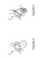
- FIG. 4is a top perspective view of an exemplary charging housing in accordance with exemplary implementation of embodiments of the present invention.
- FIG. 5is an enlarged view of a lid of the charging housing shown in FIG. 4 in accordance with exemplary implementation of embodiments of the present invention.
- FIG. 6is top perspective view of the charging housing shown in Figure without a cover in accordance with exemplary implementation of embodiments of the present invention.
- FIG. 7is a sectional view of the charging housing shown in FIG. 4 in accordance with exemplary implementation of embodiments of the present invention.
- FIG. 8is a top perspective view of an exemplary control module in accordance with exemplary implementation of embodiments of the present invention.
- FIG. 9is a sectional view of the control module shown in FIG. 8 in accordance with exemplary implementation of embodiments of the present invention.
- FIG. 10is a top perspective view of the charging unit shown in FIG. 4 without the housing body in accordance with exemplary implementation of embodiments of the present invention.
- FIG. 11is a top perspective view of the charging unit shown in FIG. 4 without the housing body and the coil in accordance with exemplary implementation of embodiments of the present invention.
- FIG. 12is a top perspective view of the charging unit shown in FIG. 4 showing electrical components in accordance with exemplary implementation of embodiments of the present invention.
- FIG. 13is a right-side view of the electrical components shown in FIG. 12 in accordance with exemplary implementation of embodiments of the present invention.
- FIG. 14illustrates an example of a log in screen of the application in accordance with exemplary implementation of embodiments of the present invention.
- FIG. 15is a diagram illustrating an example of a registration process in accordance with exemplary implementation of embodiments of the present invention.
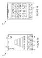
- FIG. 16is a diagram illustrating and example of an initial account process in accordance with exemplary implementation of embodiments of the present invention.
- FIG. 17is a diagram illustrating an example of a log in process in accordance with exemplary implementation of embodiments of the present invention.
- FIG. 18depicts an exemplary charging screen of the application in accordance with exemplary implementation of embodiments of the present invention.
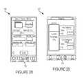
- FIG. 19depicts an exemplary account screen of the application in accordance with exemplary implementation of embodiments of the present invention.
- FIG. 20depicts an exemplary location list screen of the application in accordance with exemplary implementation of embodiments of the present invention.
- FIG. 21depicts an exemplary map screen of the application in accordance with exemplary implementation of embodiments of the present invention.
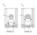
- FIG. 22depicts an exemplary parking sequence screen of the application in accordance with exemplary implementation of embodiments of the present invention.
- FIG. 23depicts another exemplary parking sequence screen of the application in accordance with exemplary implementation of embodiments of the present invention.
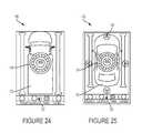
- FIG. 24depicts another exemplary parking sequence screen of the application in accordance with exemplary implementation of embodiments of the present invention.
- FIG. 25depicts another exemplary parking sequence screen of the application in accordance with exemplary implementation of embodiments of the present invention.
- FIG. 26depicts another exemplary parking sequence screen of the application in accordance with exemplary implementation of embodiments of the present invention.
- FIG. 27depicts an exemplary charging method screen of the application in accordance with exemplary implementation of embodiments of the present invention.
- FIG. 28depicts an exemplary payment screen of the application in accordance with exemplary implementation of embodiments of the present invention.
- FIG. 29depicts an exemplary analytics screen of the application in accordance with exemplary implementation of embodiments of the present invention.
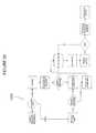
- FIG. 30is a diagram illustrating an example of a reservation process in accordance with exemplary implementation of embodiments of the present invention.
- FIG. 31is a diagram illustrating an example of a use process in accordance with exemplary implementation of embodiments of the present invention.
- FIG. 32depicts a general view of a charging zone in accordance with exemplary implementation of embodiments of the present invention.
- FIG. 33is another illustration of a general view of a charging zone in accordance with exemplary implementation of embodiments of the present invention.
- FIG. 34is a diagram illustrating an example of a reservation process in accordance with exemplary implementation of embodiments of the present invention.
- charging stations 10may be utilized for personal and commercial electric vehicles 12 .
- Charging stations 10may be placed in designated areas on public streets and on private or city land, such as garages and warehouses used to park or store personal and commercial electric vehicles 12 . Though charging stations 10 may be placed anywhere, placement may be optimized to support and promote electric charging in specific zones, such as residential areas. Charging stations 10 may also be effective, for example for commercial vehicles 12 , in designated loading zones.
- a delivery truckmay recharge while offloading goods, extending the range of the delivery truck and enabling secondary systems, such as refrigeration, to be run off of electric batteries.
- FIG. 2depicts a vehicle 12 positioned above a charging station 10 .
- a personal vehicle 12is shown, the operation for charging commercial vehicles is essentially the same.
- the vehicle 12parks above a charger housing 14 that may be positioned below street level as shown in FIG. 2 , though various components of the charging station 10 may also be positioned at or above street level.
- An exemplary housing 14is depicted in FIG. 3 .
- the housing 14includes an outer body 16 surrounding an interior and a removable cover 18 allowing access to the interior of the housing body 16 .
- the interiorreceives and retains components associated with charging the vehicle 12 and performing various other operations as described herein.
- the cover 18may be similar to a typical manhole cover and may including various locks or other security features to prevent unauthorized access to the housing 14 .
- the housing 14may be waterproof and shock proof, and be capable of withstanding various loads. In an exemplary embodiment, the housing 14 is rated at 25 ton PSI resistance.
- the housing 14may include various passages for wires and components. These passages may include seals or valves as needed.
- the housingmay also include various thermal or electromagnetic shielding.
- the housing 14may be made from materials comprising metals, polymers, ceramics, and composite materials. The materials may incorporate various fillers and reinforcements such as fiberglass.
- the housing 14may contain various electronic and mechanical components associated with the charging station 10 .
- a charging unit 20is positioned in the housing 14 .
- the charging unit 20may be positioned proximate the cover 18 in order to reduce the distance between the charging unit 20 and a receiver 22 positioned on the vehicle 12 .
- the charging unit 20is capable of wirelessly transmitting power to the receiver 22 and may be capable of fast charging at higher voltages and currents.
- the charging unit 20 and the receiver 22may include various configurations of coils having different sizes, orientations, number of loops, and loop diameters, and made from different materials for transmitting and receiving power through induction or magnetic resonance.
- Various exemplary embodimentsmay also utilize other forms of wireless power transfer, such as electromagnetic radiation.
- the receiver 22is electrically connected to a battery unit 24 which may include one or more rechargeable batteries and a battery management system 25 .
- the battery management system 25is capable of monitoring one or more properties of the batteries, for example charge level, charging rate, temperature, and usage efficiency.
- the receiver 22is capable of transferring power received from the charging station 10 to charge the batteries.
- Various electrical componentssuch as power converters, rectifiers and various control units may be associated with the charging unit 20 and the receiver 22 .
- Various componentsmay also be positioned outside of the housing 14 as desired, including the charging unit 20 .
- a more detailed schematic of an exemplary power systemis shown in FIG. 3 .
- the charging unit 20is connected to a control unit 26 .
- the control unit 26may include various electronic, mechanical, and/or electromechanical components to perform various control, analytical, and communication functions such as those described herein.
- the control unit 26may include one or more microcontrollers, such as an PC board to perform dedicated tasks and functions. Though the control unit 26 is depicted and described as a single unit for clarity, it may be comprised of several individual units, working together or in isolation, to perform the various functions described herein.
- the control unit 26may be connected to a power source 28 , for example an electrical utility line.
- the control unit 26may contain various electronic components to convert or modify the power received from the power source 28 and supply the charging unit 20 with power in an appropriate amount, having the correct current and frequency.
- the control unit 26is capable of selectively powering the charging unit 20 at appropriate times, such as by activating the charging unit 20 when a vehicle 12 is detected or a request for charging is received, or by deactivating the charging unit 20 when a vehicle 12 leaves or the battery 24 is completely charged.
- the charging station 10may include one or more sensors 30 used to determine the position of the vehicle 12 .
- the sensors 30may be located in the housing 14 as depicted in FIG. 2 and also may be located remotely from the housing 14 .
- Various types of sensorsincluding visual sensors, proximity sensors, pressure sensors, infrared sensors, and GPS sensors may be used.
- the control unit 26may be capable of receiving and analyzing signals from the sensors 30 or a dedicated unit may analyze the output from the sensors 30 .
- the sensorsmay also be configured to determine if any foreign objects are in or around the charging station 10 . This information may be communicated to users for safety reasons and may also be communicated to a monitor or manager of the system or a city department to investigate or remove any foreign objects. Foreign object detection may also prevent or discontinue wireless charging when it is determined that a foreign object is present between the charging unit 20 and the receiver 22 to prevent harm, damage, or other incident.
- the control unit 26may contain, or be connected to, a communication unit 32 to receive and transmit information from various sources.
- the communication unit 32may receive and transmit information through a wired connection and/or wirelessly. Wired connections may be achieved through one or more data or network ports. Wireless communication may be achieved through radio frequency, Bluetooth, or WiFi wireless transmission as well as optic, infrared, or other light signaling.
- the communication unit 32may be in communication, either through a data connection or an electrical connection to receive and transmit information for other components in the charging station 10 .
- the communication unitmay also communicate with devices and locations outside of the charging station 10 .
- the controller 26 and the communication unit 32may incorporate a beagleboard or beaglebone type device to provide computing and communication functionality.
- the communication unit 32transmits and receives information to and from various external devices such as the battery management system 25 , the sensors 30 , and one or more mobile devices 34 .
- Mobile devices 34may include any mobile electronic device, such as a mobile phone, tablet, laptop or other computing device.
- the mobile device 34may also be a vehicle related device, such as a global positioning device (GPS), dashboard or other onboard, vehicle computer.
- GPSglobal positioning device
- a vehicle related mobile device 34may be a dedicated unit or integrated with the vehicle 12 to perform different functions.
- the mobile device 34may be capable of receiving information related to the vehicle 12 , for example position, battery level, and charging rate. Accordingly, the battery management system 25 may also be able to communicate directly with one or more mobile devices 34 .
- the communication unit 32may also be capable of transmitting and receiving information to and from a remote server 36 .
- the remote server 36may include a dedicated server or a storage network, such as a cloud computing network.
- the communication unit 32transmits information to the remote server 36 via the Internet or a dedicated network, either through a hardwired connection or wireless connection as discussed above.
- the sensors 30communicate with the remote server 36 directly or through the communication unit 32 .
- Information sent to the remote server 36may include operating status, occupancy status, charging efficiency and statics, sensor data, and usage data.
- the remote server 36may also communicate with the mobile device 34 and other devices, such as an additional user device 38 as well as an administrator system 40 .
- the user device 38may include any user computing device such as a mobile device 34 described above or a stationary computer or terminal.
- the administrator system 40may be capable of performing various tasks and operations such as monitoring, management, customer service and support, and/or scheduling.
- the administrator system 40may be capable of controlling, monitoring, testing or calibrating the sensors 30 .
- the administrator system 40may also be capable of sending alerts to users, authorities, and other relevant parties, for example police, fire, medical services, or towing services.
- the remoter server 36may be designed to interact with one or more databases 42 for storing information relating to different charging stations 10 , different vehicles 12 , and/or different users.
- the server 36may implement a database management system for storing, compiling, and organizing data, and to allow a user and administrators to access and search the stored data.
- the databases 42may contain different units for storing data related to different topics, for example charging station 10 information, user account information, and vehicle 12 information.
- FIGS. 4-11depict certain components of an exemplary charging station 10 in greater detail.
- the housing body 16may be an enclosure formed from concrete.
- a mounting ring 44is positioned on the housing body 16 .
- the cover 18rests on the mounting ring 44 .
- the mounting ring 44may help seal the housing 14 , and may allow the charging unit 20 to be mounted close to the cover 18 .
- a conduit 46is provided in the housing body 16 to receive one or more utility lines 48 , for example an external power cable and an internet cable.
- the cover 18may have an opening for receiving a control module 50 having a lid 52 which is visible and/or accessible through the cover 18 .
- the control module 50may be removable from the charging housing 14 . In various embodiments, the control module 50 may be removed from the housing 14 without removing the cover 18 .
- the lid 52may contain a set of indicators 54 , for example light emitting diodes (LEDs).
- the indicators 54may provide status notifications for the charging unit 10 , for example when the unit is currently charging and when an error has occurred.
- the indicators 54may transmit different colored light depending on the notification and may also provide visual signals.
- the lid 52may include a door 56 providing access to recess housing one or more jacks 58 .
- the jacks 58may include one or more ports including but not limited to phone, coaxial, data, USB, or Ethernet, or other electrical connector or connectors designed to send and receive data or electrical signals. An operator may connect to the jacks 58 to perform diagnostics on the charging unit 10 .
- interior of the charging housing 14includes the control module 50 and a coil 60 .
- the coil 60may be a magnetic resonance power transfer coil.
- the coil 60is supported by a mounting bracket 62 .
- the mounting bracket 62may be coupled to the mounting ring 44 .
- the mounting bracket 62may be made from a variety of materials and may be formed from a material that will not interfere with the power transfer.
- the coil 60receives power from the control module 50 through a power connector 64 .
- the control module 50houses one or more circuit boards 66 .
- the circuit boards 66may be printed circuit boards containing a variety of electronic components for performing different functions as discussed herein.
- a usermay access an application 100 that allows the user, for example and without limitation, to find an available charging station 10 , navigate to the available charging station 10 , maneuver their vehicle in a correct position for charging, pay for their charging, and monitor the status of their vehicle.
- the application 100is not limited to such a use, and may be used for any type of vehicle charging.
- the application 100may act as an interface between the remote server 36 and the user and may include various software, firmware, and hardware components for performing the various functions described herein.
- the solution stack to implement and integrate the application 100 with the overall systemmay utilize a LAMP (Linux (operating system), Apache HTTP Server, MySQL (database software), and PHP, Perl or Python) bundle or other similar solution stack.
- the application 100may be designed with one or more languages or frameworks, including HTML, such as HTML5, WML, XML, Java JavaScript, CCS, such as CCS3, Node.js, and DOM.
- HTML5HyperText Markup Language
- WMLHyperText Markup Language
- XMLJava JavaScript
- CCSsuch as CCS3, Node.js, and DOM.
- the application 100is provided as a mobile application that can be downloaded and installed by a user to a mobile device 34 .
- the application 100may also be provided as a web application accessible through the Internet.
- the application 100may integrate with other applications, services, such as location based services, and systems utilizing application integration software or middleware, for example WebSphere®.
- a usermay initially access the application 100 by download the application 100 to a mobile device 34 or by connecting to the application 100 through the Internet.
- the usermay be presented with a login screen 102 and have the option to register for an account or to login to an existing account.
- the usermay follow a registration process 1500 to register for an account by following a series of prompts. The user can select whether the account is for personal use or for business. If the account is for business use, the user may be asked to register online and provide business information such as company name, the driver's name and phone number, and a preferred method of contact.
- a usermay be asked to provide a name, date of birth, license number, phone number, email address, and a preferred method of contact. The user may then insert vehicle information including make, model, vehicle identification number (VIN), and plate number. The user may also be asked to input an identification number associated with the vehicle 12 receiver 22 . After the user provides the necessary information, they may select to create an account.
- vehicle informationincluding make, model, vehicle identification number (VIN), and plate number.
- VINvehicle identification number
- plate numberThe user may also be asked to input an identification number associated with the vehicle 12 receiver 22 . After the user provides the necessary information, they may select to create an account.
- the application 100may institute a push notification transmitting a verification code to a user's email account and/or phone through, for example, a Short Message Service (SMS).
- SMSShort Message Service
- the usermay be directed to a screen to enter the received verification code to activate their account. If the verification code is rejected the user may have a certain number of tries to reenter the code. If the verification code is continually rejected, a different verification code may be sent. If the verification code is accepted, the user may be then asked to create a password. Once a suitable password has been created, the user may select a security question, either from a predetermined list or by setting up a security questions and answer in a free-form field. The user may then be given the option of selecting an avatar or profile picture. Picture options may be provided by the application and uploaded by a user. Once the user's account is finalized, the user may be redirected to the login screen 102 to login and access the application.
- SMSShort Message Service
- the usermay then go through an initial login process 1600 , an example of which is depicted in FIG. 16 .
- a usermay be presented with options to set up personal preferences.
- the usermay link one or more methods of payment to their account, including a debit card, credit card, bank account, or an electronic payment service such as PayPal® or Google Wallet®.
- Various forms of encryptions and secure protocolsmay be used to protect financial data.
- the usermay select which payment method is to be used as a default.
- the usermay also be given the option to select a default power method.
- the usermay choose to charge their vehicle by a set dollar amount, a set battery percentage, or a set time.
- After a user sets up preferencesuser may be provided with a “Terms of Use” agreement. This agreement must be accepted prior to completing users account setup.
- FIG. 17depicts an exemplary login process 1700 .
- the application 100performs a recognition of the user's username or avatar and password. If the password is accepted the user is logged into the application. If the password is rejected a user may have the option to reenter their password or perform a password retrieval. The user may then be posed with one or more security questions. If the user answers the questions wrong they may be given the option to call a customer service representative for assistance and account verification. If the security questions are answered correctly, a temporary password may be transmitted to the user, for example by email or SMS. The user enters the temporary password into the login screen 102 . If the temporary password is rejected, it may be tried again or resent. If the temporary password is accepted, the user may log into their account and be prompted to reset or create a new password.
- FIG. 18depicts an exemplary charging screen showing the tool bar and the icons.
- the iconsmay include an account button 108 , a locations button 110 , a power button 112 for exiting and/or deactivating the application, and a settings button 114 .
- the account button 108can direct the user to the account home screen 116 as shown in FIG. 19 .
- the account home screen 116allows a user to add guests, add vehicles, change payment options, change power options, change their avatar, change their password, view their usage history, view acquired points (obtained through usage of the system), and view the Terms of Use.
- the usermay also select the locations button 110 to access a location list 118 as depicted in FIG. 20 .
- the location list 118can display charging stations 10 in the area.
- the application 100may use or receive information from a location service such as GPS or other cellular-site location system.
- the application 100receives user positioning data and displays charging stations 10 ordered by location closest to the user.
- the usermay also have the option to search other locations for charging stations 10 , for example by address or zip code.
- the location list 118also conveys to the user whether a particular charging station is vacant or occupied through visual indicia, for example different colored icons.
- the usermay select a charging station 10 that is occupied and be given the option to receive a notification, for example by email or SMS, when the charging station 10 becomes vacant. When a desired location is found, the user may select the appropriate charging station 10 . Information about the selected charging station 10 may then be displayed to the user.
- the application 100utilizes an integrated or embedded geographic information system or mapping service 120 as shown in FIG. 21 .
- An example of such a mapping serviceis Google Maps® or OpenStreetMap which may be integrated through an application programming interface.
- the mapping service 120may be activated when a charging station 10 is selected from the location list 118 , or may be independently accessed by the user through the application 100 .
- the mapping service 120can show the location of charging stations 10 relative to the user.
- the mapping service 120along with other parts of the application 100 , may display information relating to each charging station 10 viewed by the user. For example, the mapping service 120 may show whether charging stations 10 are occupied or vacant, the amount of time before an occupied charging station 10 is vacant, and the average wait time for a specific charging station 10 .
- the mapping service 120may show a picture of the charging station 10 so that the user will be familiar with the location upon arrival. If desired by the user, the mapping service 120 provides directions from the user location to the selected charging station. The mapping service 120 may continually update to provide turn-by-turn directions to the user, guiding them to the selected charging station 10 . The mapping service 120 may also provide information on points of interest in the area surrounding the charging station 10 , including parks, museums, galleries, restaurants, shops, and bars.
- the usermay reserve a charging station 10 ahead of time. Reservations may be made by selecting the charging station 10 , for example from the location list 118 or from the mapping service 120 . Reservations may be made in advance by a user for a specific time for each charging station 10 and stored in a database 42 . The application 100 may then indicate to other users that the reserved charging station 10 is in use. Reservation information may be stored in a database 42 and accessed as needed. The application 100 may transmit reminders to a user of a stored reservation, for example by email or SMS. The user may cancel within a certain timeframe prior to their reservation. The application 100 may use location data received from a user or a vehicle 12 to determine if the vehicle is in or near the appropriate charging station 10 at the reserved time.
- the application 100may cancel the reservation or transmit an additional reminder or a reservation confirmation message to a user. If the user fails to respond to the messages or responds that they wish to cancel the reservation, the reservation is canceled and the charging station 10 is listed as vacant. Various penalties, including a cancellation fee may be applied to a user's account for missing a reservation.
- the position of the vehicle 12may be detected by the charging station 10 and a parking sequence 122 may be initiated by the application 100 to assist the user with aligning the vehicles receiver 22 with the charging unit 20 . Improper alignment can lead to less power transfer and inefficient charging.
- the presence and position of the vehicle 12may be detected by the charging station 10 sensors 30 , by positioning and location data received by the application 100 , or by any combination thereof.
- the application 100is designed to communicate with the remote server 36 , the charging station 10 , and/or the vehicle 12 to send and receive information regarding positioning.
- the parking sequence 122displays a charging unit icon 124 and a vehicle icon 126 .
- the parking sequencemay also include directional arrows 128 indicating which direction the vehicle needs to go to align with the charging unit 20 .
- the application 100may provide a visual signal to the user when the vehicle 12 is properly aligned.
- the charging unit icon 124 and/or the vehicle unit icon 126may have an initial color as the vehicle 12 initially approaches the charging station 10 as shown in FIG. 22 .
- the icons 124 , 126may be red.
- the charging unit icon 124 and/or the vehicle unit icon 126may brighten or change color as the vehicle approaches alignment as best shown in FIG. 23 .
- the icons 124 , 126may be yellow.
- the charging unit icon 124 and/or the vehicle unit icon 126may finally brighten or change color when the vehicle 12 is properly aligned with the charging unit 20 as shown in FIGS. 24 and 25 .
- the charging unit icon 124may turn green and the vehicle unit icon 126 may turn blue.
- the application 100may provide one or more audio signals to alert the user that the vehicle is in the initial, intermediate, and final alignment stages, either in connection with the visual signals or in place of the visual signals.
- the parking sequence 122may also alert a user when they have gone past a proper alignment as best shown in FIG. 26 .
- the charging stations 10 in the networkmay have an identical layout as to the position of the charging unit 20 and the receivers 22 of each vehicle 12 may be placed in a uniform position relative to, for example, the front of the car. In this way, the parking sequence 122 may perform a relatively uniform determination for all parking sequences 122 . In alternative embodiments, however, the charging units 20 and/or the receivers 22 may have non-uniform placement.
- the charging unit 10 and application 100may communicate, either directly or through the remote server 36 to assist in properly aligning the vehicle 12 .
- the charging station 10may be capable of recognizing the placement of each individual vehicle receiver 22 , for example by a specific vehicle 12 or receiver 22 identifier that is transmitted to the charging station.
- the transmissionmay be through, a radio transmission, WiFi, or Bluetooth or through a form of inductance communication at a specific frequency between the receiver 22 and the charging unit 20 .
- the charging station 10may also supply charging unit 20 position data to the application 100 , either directly or through the remote server 36 .
- the applicationmay compare this data to stored data representing the receiver position 22 to facilitate proper alignment.
- the data representing the receiver position 22may be entered or selected by a user, or it may be transmitted by the receiver 22 or another component of the vehicle 12 to the application 100 .
- a charging method screen 130may be selected or automatically displayed to the user.
- An example of a charging method screen 130is depicted in FIG. 27 .
- the usermay select a default option that was established at registration or through the account home screen 116 .
- the usermay also select to charge their car based on a dollar amount, up to a certain battery percentage, or for a certain amount of time.
- theymay be automatically billed for the amount of charging performed or they may be directed to a payment screen 132 , as shown in the example of FIG. 28 , where a user may select various payment methods.
- the usermay also select the method of payment after selecting the charging method.
- the application 100may show a charging screen 104 .
- the charging screen 104provides a battery indicator 106 representing an approximation of the electrical vehicles charge. This information may be received directly from the vehicle, for example via a Bluetooth® connection.
- the usermay navigate to an analytic screen 134 .
- This screenmay show different statistics to the user.
- the analytic screen 134may display the vehicle's current battery percentage, the amount of money being spent on charging, and the amount of CO 2 emissions saved based on travel distance.
- the staticsmay also include the rate of charging and charging efficiency while at a charging station 10 .
- Various other monitoring information, alerts, and messages, such as a charging error alert,may be sent to user during charging. These communications may be sent through the remote server 36 or directly to the user device 38 .
- Various other staticsmay also be selected.
- FIG. 30depicts and exemplary system and method for a reservation process 3000 allowing a user to locate and reserve a charging station 10 , for example in a designated “Green Parking Zone”.
- Green Parking ZoneGPZ
- the term “Green Parking Zone” (GPZ)is used herein simply as a non-limiting reference label for consistency of description and to facilitate understanding of exemplary implementations.
- the reservation process 3000may utilize any combination of the administrator system 40 , database 42 , and other components described herein.
- a useraccess the application 100 or a website and enters login information. Accessing the system may bring a user to a map showing GPZ locations or dropdown list of GPZ locations. A user selects a specific location and may be presented with available times. A user then selects a time and can be given the option to confirm the reservation. After the reservation is confirmed, it may be stored and an email notification may be sent to the user.
- FIG. 31depicts an exemplary process 3100 describing the system and method for utilizing the charging stations 10 and application 100 described herein.
- a userlogs into the system through the application 100 or a website.
- the useris provided with a map showing the current locations and available GPZs.
- the userselects a location and may be given the option to reserve a charging station 10 .
- a mapopens showing the location, route and travel time to the reserved GPZ.
- the parking sequence 122is initiated and displayed to the user guiding the user to the optimal parking position in real time.
- the useris then given the option to choose a charging method, for example the charging screen 130 .
- the useris provided with an appropriate screen. For example, if the user selects charging by a certain dollar amount, they may be provided with a screen that allows them to enter a desired dollar amount. If the user selects a battery percentage, they may be provided with a screen that allows them to enter a desired percentage for charging. If the user selects an amount of time, they may be provided with a screen that allows them to enter a desired amount of time. After the user confirms their selects they may be provided with a screen that allows them to initiate charging. In various exemplary embodiments, the user must initiate charging within a set amount of time or the screen will time-out.
- the systemmay be capable of determining an approximate time when charging will be complete.
- the systemmay make this calculation on information received from the battery management system 25 and information related to the charging rate and efficiency. This calculation may be performed at specific intervals and updated as needed.
- the usermay be provided with messages or alerts informing them of when their charging will be complete. In an exemplary embodiment, when approximately 10 minutes is remaining, a message may be sent to the user.
- the usermay select to terminate the charging and leave the GPZ.
- a receipt screenis shown after the charging is terminated, a copy of which may be sent to the user, for example by email.
- Information of the transactionmay be sent to the remote server 36 . If the user does not move their vehicle 12 within the set amount of time, the user may be charged a late fee. This encourages turn-over and assists in providing proper scheduling and information to additional users.
- the application 100may provide additional communications to the user based on geo-location and system usage data. For example, user location, charging station 10 usage, and reserved charging station 10 location data may trigger various communications to the user. These communications may be displayed through the application 100 or push notifications that are sent to the user, for example by email or SMS message. The communication may transmit advertisements or coupons to a user.
- GLZsGreen Loading Zones
- GLZsGreen Loading Zones
- GLZs 136provide wireless charging and parking in public areas for an established rate to all registered vehicles. This allows commercial fleet operators to charge their vehicles while loading and unloading payloads, thus, streamlining deliveries and work schedules.
- GLZs 136can address, for example, the problem of range limitation that commercial fleets face by strategically positioning and installing charging stations 10 at GLZs 136 , loading facilities, and company-owned parking lots.
- GLZs 136can provide commercial fleet operators the opportunity to optimize fleet logistics and make the adoption of electric trucks cost-effective, efficient, and practical.
- GLZs 136may also enable secondary vehicle systems, such as climate control systems to move from gas or diesel power to electric.
- GLZs 136may be implemented by the application 100 and the remote server 36 .
- a dedicated database 42may compile and log information relating to the GLZs 136 , for example scheduling and usage information.
- a companymay schedule a delivery ahead of time and reserve a particular charging station 10 .
- a companymay also have a dedicated daily/weekly/monthly time window for utilizing a GLZ 136 . Scheduling and reservation of certain GLZs 136 may be optimized to increase delivery efficiency, reducing not only emissions, but congestion and gridlock caused by multiple delivery trucks or other commercial vehicles attempting to occupy and utilize a limited space.
- FIG. 34depicts and exemplary system and method for a GLZ reservation process 3400 allowing a user to locate and reserve GLZs.
- the GPZs or GLZs 136may also be reserved or utilized to provide power to construction crews, emergency services such as lighting and command center, and other official vehicles and devices that typically need to be run off of generators or connected to light posts for operation. If an occupied charging station 10 is needed on an emergency basis, an alert may be sent to a user informing them of the need to remove their vehicle immediately or a notice that the vehicle has been towed or relocated.
- exemplary implementations of above-described exemplary embodimentsmay be recorded in computer-readable media including program instructions to implement various operations embodied by a computer.
- the mediamay also include, alone or in combination with the program instructions, data files, data structures, and the like.
- the media and program instructionsmay be those specially designed and constructed for the purposes of the present invention, or they may be of the kind well-known and available to those having skill in the computer software arts.
- Examples of computer-readable mediainclude magnetic media such as hard disks, floppy disks, and magnetic tape; optical media such as CD ROM disks and DVD; magneto-optical media such as optical disks; and hardware devices that are specially configured to store and perform program instructions, such as read-only memory (ROM), random access memory (RAM), flash memory, and the like.
- the mediamay also be a transmission medium such as optical or metallic lines, wave guides, and so on, including a carrier wave transmitting signals specifying the program instructions, data structures, and so on.
- Examples of program instructionsinclude both machine code, such as produced by a compiler, and files containing higher level code that may be executed by the computer using an interpreter.
- the described hardware devicesmay be configured to act as one or more software modules in order to perform the operations of the above-described embodiments of the present invention.
Landscapes
- Engineering & Computer Science (AREA)
- Power Engineering (AREA)
- Transportation (AREA)
- Mechanical Engineering (AREA)
- Computer Networks & Wireless Communication (AREA)
- Electric Propulsion And Braking For Vehicles (AREA)
- Charge And Discharge Circuits For Batteries Or The Like (AREA)
Abstract
Description
Claims (18)
Priority Applications (6)
| Application Number | Priority Date | Filing Date | Title |
|---|---|---|---|
| US13/849,904US9796280B2 (en) | 2012-03-23 | 2013-03-25 | Systems and mobile application for electric wireless charging stations |
| PCT/US2013/033720WO2013142866A1 (en) | 2012-03-23 | 2013-03-25 | Systems and mobile application for electric wireless charging stations |
| US15/722,598US11052778B2 (en) | 2012-03-23 | 2017-10-02 | Systems and mobile application for electric wireless charging stations |
| US17/367,178US20210394632A1 (en) | 2012-03-23 | 2021-07-02 | Systems and mobile application for electric wireless charging stations |
| US17/367,155US11975624B2 (en) | 2012-03-23 | 2021-07-02 | Systems and mobile application for electric wireless charging stations |
| US18/625,700US20240246437A1 (en) | 2012-03-23 | 2024-04-03 | Systems and mobile application for electric wireless charging stations |
Applications Claiming Priority (3)
| Application Number | Priority Date | Filing Date | Title |
|---|---|---|---|
| US201261614604P | 2012-03-23 | 2012-03-23 | |
| US201361794237P | 2013-03-15 | 2013-03-15 | |
| US13/849,904US9796280B2 (en) | 2012-03-23 | 2013-03-25 | Systems and mobile application for electric wireless charging stations |
Related Child Applications (1)
| Application Number | Title | Priority Date | Filing Date |
|---|---|---|---|
| US15/722,598ContinuationUS11052778B2 (en) | 2012-03-23 | 2017-10-02 | Systems and mobile application for electric wireless charging stations |
Publications (2)
| Publication Number | Publication Date |
|---|---|
| US20140021908A1 US20140021908A1 (en) | 2014-01-23 |
| US9796280B2true US9796280B2 (en) | 2017-10-24 |
Family
ID=49223389
Family Applications (5)
| Application Number | Title | Priority Date | Filing Date |
|---|---|---|---|
| US13/849,904Active - Reinstated2034-04-29US9796280B2 (en) | 2012-03-23 | 2013-03-25 | Systems and mobile application for electric wireless charging stations |
| US15/722,598Active2034-11-08US11052778B2 (en) | 2012-03-23 | 2017-10-02 | Systems and mobile application for electric wireless charging stations |
| US17/367,155Active2034-07-28US11975624B2 (en) | 2012-03-23 | 2021-07-02 | Systems and mobile application for electric wireless charging stations |
| US17/367,178PendingUS20210394632A1 (en) | 2012-03-23 | 2021-07-02 | Systems and mobile application for electric wireless charging stations |
| US18/625,700PendingUS20240246437A1 (en) | 2012-03-23 | 2024-04-03 | Systems and mobile application for electric wireless charging stations |
Family Applications After (4)
| Application Number | Title | Priority Date | Filing Date |
|---|---|---|---|
| US15/722,598Active2034-11-08US11052778B2 (en) | 2012-03-23 | 2017-10-02 | Systems and mobile application for electric wireless charging stations |
| US17/367,155Active2034-07-28US11975624B2 (en) | 2012-03-23 | 2021-07-02 | Systems and mobile application for electric wireless charging stations |
| US17/367,178PendingUS20210394632A1 (en) | 2012-03-23 | 2021-07-02 | Systems and mobile application for electric wireless charging stations |
| US18/625,700PendingUS20240246437A1 (en) | 2012-03-23 | 2024-04-03 | Systems and mobile application for electric wireless charging stations |
Country Status (2)
| Country | Link |
|---|---|
| US (5) | US9796280B2 (en) |
| WO (1) | WO2013142866A1 (en) |
Cited By (25)
| Publication number | Priority date | Publication date | Assignee | Title |
|---|---|---|---|---|
| US20160031333A1 (en)* | 2014-08-04 | 2016-02-04 | Hyundai Mobis Co., Ltd. | Wireless power transmission device having user interface structure and method for controlling the same |
| US20170012474A1 (en)* | 2014-03-21 | 2017-01-12 | Ihi Corporation | Wireless power transfer system |
| US20170253180A1 (en)* | 2016-03-01 | 2017-09-07 | Ford Global Technologies, Llc | Customizable vehicle charge status tones |
| US20170282736A1 (en)* | 2016-04-01 | 2017-10-05 | Ijuze Corporation Pte Ltd. | Automated system for managing and providing a network of charging stations |
| US20180056799A1 (en)* | 2016-08-23 | 2018-03-01 | GM Global Technology Operations LLC | Hands-free conductive battery charger for an electric vehicle |
| US20180272874A1 (en)* | 2012-03-23 | 2018-09-27 | Hevo Inc. | Systems and mobile application for electric wireless charging stations |
| DE202017107131U1 (en)* | 2017-11-24 | 2019-01-10 | Bombardier Primove Gmbh | Movable part of a device for inductive energy transmission and device for inductive energy transmission |
| US10252619B2 (en)* | 2015-12-18 | 2019-04-09 | Innogy Se | Safety module and charging station provided with a safety module |
| US10755283B1 (en)* | 2015-04-15 | 2020-08-25 | United Services Automobile Association (Usaa) | Automated vehicle ownership support |
| US10892088B1 (en)* | 2020-02-13 | 2021-01-12 | Texas Institute Of Science, Inc. | Stationary device for contactless electrical energy transmission |
| US20210080282A1 (en)* | 2017-04-03 | 2021-03-18 | Power Hero Corp. | Universal automated system for identifying, registering and verifying the existence, location and characteristics of electric and other power outlets by random users and for retrieval and utilization of such parametric data and outlets by all users |
| US10965155B2 (en)* | 2017-10-06 | 2021-03-30 | Sew-Eurodrive Gmbh & Co. Kg | System for non-contact transmission of electrical energy to a mobile part |
| US11018530B2 (en) | 2018-08-31 | 2021-05-25 | Ge Hybrid Technologies, Llc | Wireless power transmission apparatus with multiple controllers |
| US20210347278A1 (en)* | 2020-05-06 | 2021-11-11 | Toyota Motor Engineering & Manufacturing North America, Inc. | Apparatus and method for assembly line charging of vehicle batteries |
| US11223222B2 (en) | 2019-09-13 | 2022-01-11 | Texas Institute Of Science, Inc. | Contactless charging apparatus and method for contactless charging |
| US11240941B2 (en)* | 2018-09-12 | 2022-02-01 | Toyota Motor Engineering & Manufacturing North America, Inc. | Autonomous vehicle lidar cooling system |
| US11300685B2 (en)* | 2016-11-02 | 2022-04-12 | Bayerische Motoren Werke Aktiengesellschaft | Method for providing correction data for determining position |
| US11437855B2 (en) | 2017-12-22 | 2022-09-06 | Wireless Advanced Vehicle Electrification, Llc | Wireless power transfer pad with multiple windings and magnetic pathway between windings |
| US11441917B2 (en) | 2019-08-14 | 2022-09-13 | Honda Motor Co., Ltd. | System and method for adjusting an electric vehicle charging speed |
| US11836737B1 (en) | 2015-04-15 | 2023-12-05 | United Services Automobile Association (Usaa) | Automated vehicle ownership support |
| US11916405B2 (en) | 2019-01-02 | 2024-02-27 | Ge Hybrid Technologies, Llc | Wireless power transmission apparatus with multiple controllers |
| US12117498B2 (en) | 2019-08-14 | 2024-10-15 | Honda Motor Co., Ltd. | System and method for presenting electric vehicle charging options based on a predicted charging speed |
| US12142934B2 (en) | 2020-02-26 | 2024-11-12 | Ge Intellectual Property Licensing, Llc | Overlapping secondary coils in a wireless power reception apparatus |
| US12206256B2 (en) | 2019-11-12 | 2025-01-21 | Ge Hybrid Technologies, Llc | Wireless power transfer with load sharing receivers |
| US12206255B2 (en) | 2019-01-02 | 2025-01-21 | Dolby Laboratories Inc. | Wireless power transmission using multiple transmitters and receivers |
Families Citing this family (308)
| Publication number | Priority date | Publication date | Assignee | Title |
|---|---|---|---|---|
| US11370313B2 (en) | 2011-04-25 | 2022-06-28 | Emerging Automotive, Llc | Methods and systems for electric vehicle (EV) charge units and systems for processing connections to charge units |
| US9371007B1 (en)* | 2011-04-22 | 2016-06-21 | Angel A. Penilla | Methods and systems for automatic electric vehicle identification and charging via wireless charging pads |
| US9648107B1 (en) | 2011-04-22 | 2017-05-09 | Angel A. Penilla | Methods and cloud systems for using connected object state data for informing and alerting connected vehicle drivers of state changes |
| US9493130B2 (en) | 2011-04-22 | 2016-11-15 | Angel A. Penilla | Methods and systems for communicating content to connected vehicle users based detected tone/mood in voice input |
| US9809196B1 (en) | 2011-04-22 | 2017-11-07 | Emerging Automotive, Llc | Methods and systems for vehicle security and remote access and safety control interfaces and notifications |
| US9230440B1 (en) | 2011-04-22 | 2016-01-05 | Angel A. Penilla | Methods and systems for locating public parking and receiving security ratings for parking locations and generating notifications to vehicle user accounts regarding alerts and cloud access to security information |
| US9365188B1 (en) | 2011-04-22 | 2016-06-14 | Angel A. Penilla | Methods and systems for using cloud services to assign e-keys to access vehicles |
| US9104537B1 (en) | 2011-04-22 | 2015-08-11 | Angel A. Penilla | Methods and systems for generating setting recommendation to user accounts for registered vehicles via cloud systems and remotely applying settings |
| US9189900B1 (en) | 2011-04-22 | 2015-11-17 | Angel A. Penilla | Methods and systems for assigning e-keys to users to access and drive vehicles |
| US12337716B2 (en) | 2011-04-22 | 2025-06-24 | Emerging Automotive, Llc | Systems for transferring user profiles between vehicles using cloud services |
| US9818088B2 (en) | 2011-04-22 | 2017-11-14 | Emerging Automotive, Llc | Vehicles and cloud systems for providing recommendations to vehicle users to handle alerts associated with the vehicle |
| US9285944B1 (en) | 2011-04-22 | 2016-03-15 | Angel A. Penilla | Methods and systems for defining custom vehicle user interface configurations and cloud services for managing applications for the user interface and learned setting functions |
| US11203355B2 (en) | 2011-04-22 | 2021-12-21 | Emerging Automotive, Llc | Vehicle mode for restricted operation and cloud data monitoring |
| US10217160B2 (en)* | 2012-04-22 | 2019-02-26 | Emerging Automotive, Llc | Methods and systems for processing charge availability and route paths for obtaining charge for electric vehicles |
| US9180783B1 (en) | 2011-04-22 | 2015-11-10 | Penilla Angel A | Methods and systems for electric vehicle (EV) charge location color-coded charge state indicators, cloud applications and user notifications |
| US9229905B1 (en) | 2011-04-22 | 2016-01-05 | Angel A. Penilla | Methods and systems for defining vehicle user profiles and managing user profiles via cloud systems and applying learned settings to user profiles |
| US11132650B2 (en) | 2011-04-22 | 2021-09-28 | Emerging Automotive, Llc | Communication APIs for remote monitoring and control of vehicle systems |
| US10289288B2 (en) | 2011-04-22 | 2019-05-14 | Emerging Automotive, Llc | Vehicle systems for providing access to vehicle controls, functions, environment and applications to guests/passengers via mobile devices |
| US11270699B2 (en) | 2011-04-22 | 2022-03-08 | Emerging Automotive, Llc | Methods and vehicles for capturing emotion of a human driver and customizing vehicle response |
| US11294551B2 (en) | 2011-04-22 | 2022-04-05 | Emerging Automotive, Llc | Vehicle passenger controls via mobile devices |
| US9697503B1 (en) | 2011-04-22 | 2017-07-04 | Angel A. Penilla | Methods and systems for providing recommendations to vehicle users to handle alerts associated with the vehicle and a bidding market place for handling alerts/service of the vehicle |
| US9536197B1 (en) | 2011-04-22 | 2017-01-03 | Angel A. Penilla | Methods and systems for processing data streams from data producing objects of vehicle and home entities and generating recommendations and settings |
| US9139091B1 (en) | 2011-04-22 | 2015-09-22 | Angel A. Penilla | Methods and systems for setting and/or assigning advisor accounts to entities for specific vehicle aspects and cloud management of advisor accounts |
| US10572123B2 (en) | 2011-04-22 | 2020-02-25 | Emerging Automotive, Llc | Vehicle passenger controls via mobile devices |
| US9346365B1 (en) | 2011-04-22 | 2016-05-24 | Angel A. Penilla | Methods and systems for electric vehicle (EV) charging, charging unit (CU) interfaces, auxiliary batteries, and remote access and user notifications |
| US9288270B1 (en) | 2011-04-22 | 2016-03-15 | Angel A. Penilla | Systems for learning user preferences and generating recommendations to make settings at connected vehicles and interfacing with cloud systems |
| US10824330B2 (en) | 2011-04-22 | 2020-11-03 | Emerging Automotive, Llc | Methods and systems for vehicle display data integration with mobile device data |
| US9171268B1 (en) | 2011-04-22 | 2015-10-27 | Angel A. Penilla | Methods and systems for setting and transferring user profiles to vehicles and temporary sharing of user profiles to shared-use vehicles |
| US9581997B1 (en) | 2011-04-22 | 2017-02-28 | Angel A. Penilla | Method and system for cloud-based communication for automatic driverless movement |
| US9215274B2 (en) | 2011-04-22 | 2015-12-15 | Angel A. Penilla | Methods and systems for generating recommendations to make settings at vehicles via cloud systems |
| US10286919B2 (en) | 2011-04-22 | 2019-05-14 | Emerging Automotive, Llc | Valet mode for restricted operation of a vehicle and cloud access of a history of use made during valet mode use |
| US9123035B2 (en) | 2011-04-22 | 2015-09-01 | Angel A. Penilla | Electric vehicle (EV) range extending charge systems, distributed networks of charge kiosks, and charge locating mobile apps |
| US9348492B1 (en) | 2011-04-22 | 2016-05-24 | Angel A. Penilla | Methods and systems for providing access to specific vehicle controls, functions, environment and applications to guests/passengers via personal mobile devices |
| US9963145B2 (en) | 2012-04-22 | 2018-05-08 | Emerging Automotive, Llc | Connected vehicle communication with processing alerts related to traffic lights and cloud systems |
| DE102012211151B4 (en)* | 2012-06-28 | 2021-01-28 | Siemens Aktiengesellschaft | Charging arrangement and method for inductive charging of an electrical energy store |
| US9847679B2 (en) | 2014-05-07 | 2017-12-19 | Energous Corporation | System and method for controlling communication between wireless power transmitter managers |
| US10211682B2 (en)* | 2014-05-07 | 2019-02-19 | Energous Corporation | Systems and methods for controlling operation of a transmitter of a wireless power network based on user instructions received from an authenticated computing device powered or charged by a receiver of the wireless power network |
| US9793758B2 (en) | 2014-05-23 | 2017-10-17 | Energous Corporation | Enhanced transmitter using frequency control for wireless power transmission |
| US9882427B2 (en) | 2013-05-10 | 2018-01-30 | Energous Corporation | Wireless power delivery using a base station to control operations of a plurality of wireless power transmitters |
| US10008889B2 (en) | 2014-08-21 | 2018-06-26 | Energous Corporation | Method for automatically testing the operational status of a wireless power receiver in a wireless power transmission system |
| US9954374B1 (en) | 2014-05-23 | 2018-04-24 | Energous Corporation | System and method for self-system analysis for detecting a fault in a wireless power transmission Network |
| US9838083B2 (en) | 2014-07-21 | 2017-12-05 | Energous Corporation | Systems and methods for communication with remote management systems |
| US10193396B1 (en) | 2014-05-07 | 2019-01-29 | Energous Corporation | Cluster management of transmitters in a wireless power transmission system |
| US10090699B1 (en) | 2013-11-01 | 2018-10-02 | Energous Corporation | Wireless powered house |
| US10243414B1 (en) | 2014-05-07 | 2019-03-26 | Energous Corporation | Wearable device with wireless power and payload receiver |
| US10291055B1 (en) | 2014-12-29 | 2019-05-14 | Energous Corporation | Systems and methods for controlling far-field wireless power transmission based on battery power levels of a receiving device |
| US10965164B2 (en) | 2012-07-06 | 2021-03-30 | Energous Corporation | Systems and methods of wirelessly delivering power to a receiver device |
| US10256657B2 (en) | 2015-12-24 | 2019-04-09 | Energous Corporation | Antenna having coaxial structure for near field wireless power charging |
| US9941747B2 (en) | 2014-07-14 | 2018-04-10 | Energous Corporation | System and method for manually selecting and deselecting devices to charge in a wireless power network |
| US9893555B1 (en) | 2013-10-10 | 2018-02-13 | Energous Corporation | Wireless charging of tools using a toolbox transmitter |
| US9843213B2 (en) | 2013-08-06 | 2017-12-12 | Energous Corporation | Social power sharing for mobile devices based on pocket-forming |
| US9859797B1 (en) | 2014-05-07 | 2018-01-02 | Energous Corporation | Synchronous rectifier design for wireless power receiver |
| US9887584B1 (en) | 2014-08-21 | 2018-02-06 | Energous Corporation | Systems and methods for a configuration web service to provide configuration of a wireless power transmitter within a wireless power transmission system |
| US9991741B1 (en) | 2014-07-14 | 2018-06-05 | Energous Corporation | System for tracking and reporting status and usage information in a wireless power management system |
| US10263432B1 (en) | 2013-06-25 | 2019-04-16 | Energous Corporation | Multi-mode transmitter with an antenna array for delivering wireless power and providing Wi-Fi access |
| US9973021B2 (en) | 2012-07-06 | 2018-05-15 | Energous Corporation | Receivers for wireless power transmission |
| US10199835B2 (en) | 2015-12-29 | 2019-02-05 | Energous Corporation | Radar motion detection using stepped frequency in wireless power transmission system |
| US9143000B2 (en) | 2012-07-06 | 2015-09-22 | Energous Corporation | Portable wireless charging pad |
| US9867062B1 (en) | 2014-07-21 | 2018-01-09 | Energous Corporation | System and methods for using a remote server to authorize a receiving device that has requested wireless power and to determine whether another receiving device should request wireless power in a wireless power transmission system |
| US9941754B2 (en) | 2012-07-06 | 2018-04-10 | Energous Corporation | Wireless power transmission with selective range |
| US10439448B2 (en) | 2014-08-21 | 2019-10-08 | Energous Corporation | Systems and methods for automatically testing the communication between wireless power transmitter and wireless power receiver |
| US12057715B2 (en) | 2012-07-06 | 2024-08-06 | Energous Corporation | Systems and methods of wirelessly delivering power to a wireless-power receiver device in response to a change of orientation of the wireless-power receiver device |
| US20150326070A1 (en) | 2014-05-07 | 2015-11-12 | Energous Corporation | Methods and Systems for Maximum Power Point Transfer in Receivers |
| US20140008993A1 (en) | 2012-07-06 | 2014-01-09 | DvineWave Inc. | Methodology for pocket-forming |
| US9876379B1 (en) | 2013-07-11 | 2018-01-23 | Energous Corporation | Wireless charging and powering of electronic devices in a vehicle |
| US9843201B1 (en) | 2012-07-06 | 2017-12-12 | Energous Corporation | Wireless power transmitter that selects antenna sets for transmitting wireless power to a receiver based on location of the receiver, and methods of use thereof |
| US9812890B1 (en) | 2013-07-11 | 2017-11-07 | Energous Corporation | Portable wireless charging pad |
| US9831718B2 (en) | 2013-07-25 | 2017-11-28 | Energous Corporation | TV with integrated wireless power transmitter |
| US9824815B2 (en) | 2013-05-10 | 2017-11-21 | Energous Corporation | Wireless charging and powering of healthcare gadgets and sensors |
| US10992187B2 (en) | 2012-07-06 | 2021-04-27 | Energous Corporation | System and methods of using electromagnetic waves to wirelessly deliver power to electronic devices |
| US10199849B1 (en) | 2014-08-21 | 2019-02-05 | Energous Corporation | Method for automatically testing the operational status of a wireless power receiver in a wireless power transmission system |
| US11502551B2 (en) | 2012-07-06 | 2022-11-15 | Energous Corporation | Wirelessly charging multiple wireless-power receivers using different subsets of an antenna array to focus energy at different locations |
| US9912199B2 (en) | 2012-07-06 | 2018-03-06 | Energous Corporation | Receivers for wireless power transmission |
| US10992185B2 (en) | 2012-07-06 | 2021-04-27 | Energous Corporation | Systems and methods of using electromagnetic waves to wirelessly deliver power to game controllers |
| US9847677B1 (en) | 2013-10-10 | 2017-12-19 | Energous Corporation | Wireless charging and powering of healthcare gadgets and sensors |
| US10141791B2 (en) | 2014-05-07 | 2018-11-27 | Energous Corporation | Systems and methods for controlling communications during wireless transmission of power using application programming interfaces |
| US10312715B2 (en) | 2015-09-16 | 2019-06-04 | Energous Corporation | Systems and methods for wireless power charging |
| US9923386B1 (en) | 2012-07-06 | 2018-03-20 | Energous Corporation | Systems and methods for wireless power transmission by modifying a number of antenna elements used to transmit power waves to a receiver |
| US9876648B2 (en) | 2014-08-21 | 2018-01-23 | Energous Corporation | System and method to control a wireless power transmission system by configuration of wireless power transmission control parameters |
| US10090886B1 (en) | 2014-07-14 | 2018-10-02 | Energous Corporation | System and method for enabling automatic charging schedules in a wireless power network to one or more devices |
| US10063064B1 (en) | 2014-05-23 | 2018-08-28 | Energous Corporation | System and method for generating a power receiver identifier in a wireless power network |
| US9899873B2 (en) | 2014-05-23 | 2018-02-20 | Energous Corporation | System and method for generating a power receiver identifier in a wireless power network |
| US9893768B2 (en) | 2012-07-06 | 2018-02-13 | Energous Corporation | Methodology for multiple pocket-forming |
| US9871398B1 (en) | 2013-07-01 | 2018-01-16 | Energous Corporation | Hybrid charging method for wireless power transmission based on pocket-forming |
| US10128693B2 (en) | 2014-07-14 | 2018-11-13 | Energous Corporation | System and method for providing health safety in a wireless power transmission system |
| US9787103B1 (en) | 2013-08-06 | 2017-10-10 | Energous Corporation | Systems and methods for wirelessly delivering power to electronic devices that are unable to communicate with a transmitter |
| US10050462B1 (en) | 2013-08-06 | 2018-08-14 | Energous Corporation | Social power sharing for mobile devices based on pocket-forming |
| US10224758B2 (en) | 2013-05-10 | 2019-03-05 | Energous Corporation | Wireless powering of electronic devices with selective delivery range |
| US9438045B1 (en) | 2013-05-10 | 2016-09-06 | Energous Corporation | Methods and systems for maximum power point transfer in receivers |
| US10063105B2 (en) | 2013-07-11 | 2018-08-28 | Energous Corporation | Proximity transmitters for wireless power charging systems |
| US9853692B1 (en) | 2014-05-23 | 2017-12-26 | Energous Corporation | Systems and methods for wireless power transmission |
| US9882430B1 (en) | 2014-05-07 | 2018-01-30 | Energous Corporation | Cluster management of transmitters in a wireless power transmission system |
| US10230266B1 (en) | 2014-02-06 | 2019-03-12 | Energous Corporation | Wireless power receivers that communicate status data indicating wireless power transmission effectiveness with a transmitter using a built-in communications component of a mobile device, and methods of use thereof |
| US10223717B1 (en) | 2014-05-23 | 2019-03-05 | Energous Corporation | Systems and methods for payment-based authorization of wireless power transmission service |
| US9124125B2 (en) | 2013-05-10 | 2015-09-01 | Energous Corporation | Wireless power transmission with selective range |
| US10128699B2 (en) | 2014-07-14 | 2018-11-13 | Energous Corporation | Systems and methods of providing wireless power using receiver device sensor inputs |
| US10124754B1 (en) | 2013-07-19 | 2018-11-13 | Energous Corporation | Wireless charging and powering of electronic sensors in a vehicle |
| US9887739B2 (en) | 2012-07-06 | 2018-02-06 | Energous Corporation | Systems and methods for wireless power transmission by comparing voltage levels associated with power waves transmitted by antennas of a plurality of antennas of a transmitter to determine appropriate phase adjustments for the power waves |
| US10075008B1 (en) | 2014-07-14 | 2018-09-11 | Energous Corporation | Systems and methods for manually adjusting when receiving electronic devices are scheduled to receive wirelessly delivered power from a wireless power transmitter in a wireless power network |
| US10148097B1 (en) | 2013-11-08 | 2018-12-04 | Energous Corporation | Systems and methods for using a predetermined number of communication channels of a wireless power transmitter to communicate with different wireless power receivers |
| US9876394B1 (en) | 2014-05-07 | 2018-01-23 | Energous Corporation | Boost-charger-boost system for enhanced power delivery |
| US9899861B1 (en) | 2013-10-10 | 2018-02-20 | Energous Corporation | Wireless charging methods and systems for game controllers, based on pocket-forming |
| US9891669B2 (en) | 2014-08-21 | 2018-02-13 | Energous Corporation | Systems and methods for a configuration web service to provide configuration of a wireless power transmitter within a wireless power transmission system |
| US9948135B2 (en) | 2015-09-22 | 2018-04-17 | Energous Corporation | Systems and methods for identifying sensitive objects in a wireless charging transmission field |
| US10381880B2 (en) | 2014-07-21 | 2019-08-13 | Energous Corporation | Integrated antenna structure arrays for wireless power transmission |
| US10211680B2 (en) | 2013-07-19 | 2019-02-19 | Energous Corporation | Method for 3 dimensional pocket-forming |
| US9825674B1 (en) | 2014-05-23 | 2017-11-21 | Energous Corporation | Enhanced transmitter that selects configurations of antenna elements for performing wireless power transmission and receiving functions |
| US10291066B1 (en) | 2014-05-07 | 2019-05-14 | Energous Corporation | Power transmission control systems and methods |
| US9893554B2 (en) | 2014-07-14 | 2018-02-13 | Energous Corporation | System and method for providing health safety in a wireless power transmission system |
| US10211674B1 (en) | 2013-06-12 | 2019-02-19 | Energous Corporation | Wireless charging using selected reflectors |
| US9941707B1 (en) | 2013-07-19 | 2018-04-10 | Energous Corporation | Home base station for multiple room coverage with multiple transmitters |
| US9900057B2 (en) | 2012-07-06 | 2018-02-20 | Energous Corporation | Systems and methods for assigning groups of antenas of a wireless power transmitter to different wireless power receivers, and determining effective phases to use for wirelessly transmitting power using the assigned groups of antennas |
| US9906065B2 (en) | 2012-07-06 | 2018-02-27 | Energous Corporation | Systems and methods of transmitting power transmission waves based on signals received at first and second subsets of a transmitter's antenna array |
| US9859757B1 (en) | 2013-07-25 | 2018-01-02 | Energous Corporation | Antenna tile arrangements in electronic device enclosures |
| US9939864B1 (en) | 2014-08-21 | 2018-04-10 | Energous Corporation | System and method to control a wireless power transmission system by configuration of wireless power transmission control parameters |
| US10186913B2 (en) | 2012-07-06 | 2019-01-22 | Energous Corporation | System and methods for pocket-forming based on constructive and destructive interferences to power one or more wireless power receivers using a wireless power transmitter including a plurality of antennas |
| US9252628B2 (en) | 2013-05-10 | 2016-02-02 | Energous Corporation | Laptop computer as a transmitter for wireless charging |
| US10270261B2 (en) | 2015-09-16 | 2019-04-23 | Energous Corporation | Systems and methods of object detection in wireless power charging systems |
| US10063106B2 (en) | 2014-05-23 | 2018-08-28 | Energous Corporation | System and method for a self-system analysis in a wireless power transmission network |
| US9859756B2 (en) | 2012-07-06 | 2018-01-02 | Energous Corporation | Transmittersand methods for adjusting wireless power transmission based on information from receivers |
| US10206185B2 (en) | 2013-05-10 | 2019-02-12 | Energous Corporation | System and methods for wireless power transmission to an electronic device in accordance with user-defined restrictions |
| US9806564B2 (en) | 2014-05-07 | 2017-10-31 | Energous Corporation | Integrated rectifier and boost converter for wireless power transmission |
| US10224982B1 (en) | 2013-07-11 | 2019-03-05 | Energous Corporation | Wireless power transmitters for transmitting wireless power and tracking whether wireless power receivers are within authorized locations |
| US10103582B2 (en) | 2012-07-06 | 2018-10-16 | Energous Corporation | Transmitters for wireless power transmission |
| US10218227B2 (en) | 2014-05-07 | 2019-02-26 | Energous Corporation | Compact PIFA antenna |
| US10205239B1 (en) | 2014-05-07 | 2019-02-12 | Energous Corporation | Compact PIFA antenna |
| US9966765B1 (en) | 2013-06-25 | 2018-05-08 | Energous Corporation | Multi-mode transmitter |
| US10038337B1 (en) | 2013-09-16 | 2018-07-31 | Energous Corporation | Wireless power supply for rescue devices |
| US10141768B2 (en) | 2013-06-03 | 2018-11-27 | Energous Corporation | Systems and methods for maximizing wireless power transfer efficiency by instructing a user to change a receiver device's position |
| US9368020B1 (en) | 2013-05-10 | 2016-06-14 | Energous Corporation | Off-premises alert system and method for wireless power receivers in a wireless power network |
| US9853458B1 (en) | 2014-05-07 | 2017-12-26 | Energous Corporation | Systems and methods for device and power receiver pairing |
| JP5857999B2 (en)* | 2013-04-26 | 2016-02-10 | トヨタ自動車株式会社 | Power receiving device, parking assist device, and power transmission system |
| US9819230B2 (en) | 2014-05-07 | 2017-11-14 | Energous Corporation | Enhanced receiver for wireless power transmission |
| US9538382B2 (en) | 2013-05-10 | 2017-01-03 | Energous Corporation | System and method for smart registration of wireless power receivers in a wireless power network |
| US9537357B2 (en) | 2013-05-10 | 2017-01-03 | Energous Corporation | Wireless sound charging methods and systems for game controllers, based on pocket-forming |
| US9866279B2 (en) | 2013-05-10 | 2018-01-09 | Energous Corporation | Systems and methods for selecting which power transmitter should deliver wireless power to a receiving device in a wireless power delivery network |
| US9419443B2 (en) | 2013-05-10 | 2016-08-16 | Energous Corporation | Transducer sound arrangement for pocket-forming |
| US10103552B1 (en) | 2013-06-03 | 2018-10-16 | Energous Corporation | Protocols for authenticated wireless power transmission |
| US10003211B1 (en) | 2013-06-17 | 2018-06-19 | Energous Corporation | Battery life of portable electronic devices |
| US20140375124A1 (en)* | 2013-06-24 | 2014-12-25 | Carl Lee Danner | Externally controllable battery charger having a signal interpreter |
| US10021523B2 (en) | 2013-07-11 | 2018-07-10 | Energous Corporation | Proximity transmitters for wireless power charging systems |
| US9979440B1 (en) | 2013-07-25 | 2018-05-22 | Energous Corporation | Antenna tile arrangements configured to operate as one functional unit |
| US20150095114A1 (en)* | 2013-09-30 | 2015-04-02 | Elwha Llc | Employment related information center associated with communication and control system and method for wireless electric vehicle electrical energy transfer |
| US9452685B2 (en) | 2013-09-30 | 2016-09-27 | Elwha Llc | Dwelling related information center associated with communication and control system and method for wireless electric vehicle electrical energy transfer |
| US9199548B2 (en)* | 2013-09-30 | 2015-12-01 | Elwha Llc | Communication and control regarding electricity provider for wireless electric vehicle electrical energy transfer |
| US10093194B2 (en) | 2013-09-30 | 2018-10-09 | Elwha Llc | Communication and control system and method regarding electric vehicle for wireless electric vehicle electrical energy transfer |
| US9412515B2 (en) | 2013-09-30 | 2016-08-09 | Elwha, Llc | Communication and control regarding wireless electric vehicle electrical energy transfer |
| DE102013223794A1 (en)* | 2013-11-21 | 2015-05-21 | Robert Bosch Gmbh | Energy transmission system and method for diagnosing a power transmission system |
| WO2015101997A1 (en)* | 2014-01-01 | 2015-07-09 | Powermat Technologies Ltd. | Method and system for managing wireless power transfer for electrical devices |
| US9935482B1 (en) | 2014-02-06 | 2018-04-03 | Energous Corporation | Wireless power transmitters that transmit at determined times based on power availability and consumption at a receiving mobile device |
| US10075017B2 (en) | 2014-02-06 | 2018-09-11 | Energous Corporation | External or internal wireless power receiver with spaced-apart antenna elements for charging or powering mobile devices using wirelessly delivered power |
| EP3102457A4 (en)* | 2014-02-07 | 2018-02-14 | Recargo, Inc. | Presenting routing information for electric vehicles |
| JP6329386B2 (en)* | 2014-02-21 | 2018-05-23 | ルネサスエレクトロニクス株式会社 | Non-contact power feeding method and non-contact power feeding system |
| US10158257B2 (en) | 2014-05-01 | 2018-12-18 | Energous Corporation | System and methods for using sound waves to wirelessly deliver power to electronic devices |
| US9966784B2 (en) | 2014-06-03 | 2018-05-08 | Energous Corporation | Systems and methods for extending battery life of portable electronic devices charged by sound |
| US9800172B1 (en) | 2014-05-07 | 2017-10-24 | Energous Corporation | Integrated rectifier and boost converter for boosting voltage received from wireless power transmission waves |
| US10153653B1 (en) | 2014-05-07 | 2018-12-11 | Energous Corporation | Systems and methods for using application programming interfaces to control communications between a transmitter and a receiver |
| US10153645B1 (en) | 2014-05-07 | 2018-12-11 | Energous Corporation | Systems and methods for designating a master power transmitter in a cluster of wireless power transmitters |
| US9973008B1 (en) | 2014-05-07 | 2018-05-15 | Energous Corporation | Wireless power receiver with boost converters directly coupled to a storage element |
| US10552923B2 (en)* | 2014-05-08 | 2020-02-04 | Honda Motor Co., Ltd. | Electric vehicle charging control system |
| US9876536B1 (en) | 2014-05-23 | 2018-01-23 | Energous Corporation | Systems and methods for assigning groups of antennas to transmit wireless power to different wireless power receivers |
| US20150336464A1 (en)* | 2014-05-23 | 2015-11-26 | Ford Global Technologies, Llc | Ultrasonic location for electric vehicle charging system |
| US20150365737A1 (en)* | 2014-06-11 | 2015-12-17 | Enovate Medical, Llc | Wireless transfer station with display |
| US10116143B1 (en) | 2014-07-21 | 2018-10-30 | Energous Corporation | Integrated antenna arrays for wireless power transmission |
| US10068703B1 (en) | 2014-07-21 | 2018-09-04 | Energous Corporation | Integrated miniature PIFA with artificial magnetic conductor metamaterials |
| US9871301B2 (en) | 2014-07-21 | 2018-01-16 | Energous Corporation | Integrated miniature PIFA with artificial magnetic conductor metamaterials |
| DE102014214806A1 (en)* | 2014-07-29 | 2016-02-04 | Bayerische Motoren Werke Aktiengesellschaft | Charge to charging stations for range extension |
| USD730779S1 (en) | 2014-08-15 | 2015-06-02 | Technologies Bewegen Inc. | Electric bicycle |
| USD766138S1 (en) | 2014-08-15 | 2016-09-13 | Technologies Bewegen Inc. | Base station for a bicycle sharing system |
| USD730780S1 (en) | 2014-08-15 | 2015-06-02 | Technologies Bewegen Inc. | Bicycle |
| USD746760S1 (en) | 2014-08-15 | 2016-01-05 | Technologies Bewegen Inc. | Bicycle basket |
| USD738276S1 (en) | 2014-08-18 | 2015-09-08 | Technologies Bewegen Inc. | Bicycle handlebar |
| USD776576S1 (en) | 2014-08-18 | 2017-01-17 | Technologies Bewegen Inc. | Electric bicycle |
| USD730781S1 (en) | 2014-08-18 | 2015-06-02 | Technologies Bewegen Inc. | Electric bicycle |
| US9965009B1 (en) | 2014-08-21 | 2018-05-08 | Energous Corporation | Systems and methods for assigning a power receiver to individual power transmitters based on location of the power receiver |
| US9917477B1 (en) | 2014-08-21 | 2018-03-13 | Energous Corporation | Systems and methods for automatically testing the communication between power transmitter and wireless receiver |
| US10326295B2 (en)* | 2014-08-29 | 2019-06-18 | Verizon Patent And Licensing Inc. | Method and system for providing power management for a wearable smart device |
| US9754496B2 (en) | 2014-09-30 | 2017-09-05 | Elwha Llc | System and method for management of airspace for unmanned aircraft |
| DE102014219964A1 (en)* | 2014-10-01 | 2016-04-07 | Robert Bosch Gmbh | Foreign object recognition method for an induction charging device and induction charging device |
| US10106045B2 (en)* | 2014-10-27 | 2018-10-23 | At&T Intellectual Property I, L.P. | Methods and apparatus to charge a vehicle and to facilitate communications with the vehicle |
| JP6481344B2 (en)* | 2014-11-27 | 2019-03-13 | 株式会社Ihi | Information providing system, power receiving apparatus, information providing method, and information providing program |
| US9919797B2 (en) | 2014-12-04 | 2018-03-20 | Elwha Llc | System and method for operation and management of reconfigurable unmanned aircraft |
| US20160272310A1 (en) | 2014-12-04 | 2016-09-22 | Elwha Llc | Reconfigurable unmanned aircraft system |
| US10122415B2 (en) | 2014-12-27 | 2018-11-06 | Energous Corporation | Systems and methods for assigning a set of antennas of a wireless power transmitter to a wireless power receiver based on a location of the wireless power receiver |
| US9893535B2 (en) | 2015-02-13 | 2018-02-13 | Energous Corporation | Systems and methods for determining optimal charging positions to maximize efficiency of power received from wirelessly delivered sound wave energy |
| US10444337B2 (en)* | 2015-05-22 | 2019-10-15 | Witricity Corporation | Methods and apparatus utilizing time division access of multiple radar modules in living object detection for wireless power transfer applications |
| US10027150B2 (en)* | 2015-06-18 | 2018-07-17 | Serene Devices Llc | RFI/EMI shielding enclosure containing wireless charging element for personal electronic devices security |
| US20160380439A1 (en)* | 2015-06-26 | 2016-12-29 | Lei Shao | Notification techniques for wireless power transfer systems |
| US20170015414A1 (en)* | 2015-07-15 | 2017-01-19 | Elwha Llc | System and method for power transfer to an unmanned aircraft |
| US9878787B2 (en) | 2015-07-15 | 2018-01-30 | Elwha Llc | System and method for operating unmanned aircraft |
| DE102015010324A1 (en)* | 2015-08-06 | 2016-03-03 | Daimler Ag | Method for autonomously positioning a plug-in hybrid vehicle or electric vehicle for wireless charging |
| US12283828B2 (en) | 2015-09-15 | 2025-04-22 | Energous Corporation | Receiver devices configured to determine location within a transmission field |
| US9906275B2 (en) | 2015-09-15 | 2018-02-27 | Energous Corporation | Identifying receivers in a wireless charging transmission field |
| US10523033B2 (en) | 2015-09-15 | 2019-12-31 | Energous Corporation | Receiver devices configured to determine location within a transmission field |
| US9941752B2 (en) | 2015-09-16 | 2018-04-10 | Energous Corporation | Systems and methods of object detection in wireless power charging systems |
| US10211685B2 (en) | 2015-09-16 | 2019-02-19 | Energous Corporation | Systems and methods for real or near real time wireless communications between a wireless power transmitter and a wireless power receiver |
| US10008875B1 (en) | 2015-09-16 | 2018-06-26 | Energous Corporation | Wireless power transmitter configured to transmit power waves to a predicted location of a moving wireless power receiver |
| US10158259B1 (en) | 2015-09-16 | 2018-12-18 | Energous Corporation | Systems and methods for identifying receivers in a transmission field by transmitting exploratory power waves towards different segments of a transmission field |
| US10199850B2 (en) | 2015-09-16 | 2019-02-05 | Energous Corporation | Systems and methods for wirelessly transmitting power from a transmitter to a receiver by determining refined locations of the receiver in a segmented transmission field associated with the transmitter |
| US10778041B2 (en) | 2015-09-16 | 2020-09-15 | Energous Corporation | Systems and methods for generating power waves in a wireless power transmission system |
| US10186893B2 (en) | 2015-09-16 | 2019-01-22 | Energous Corporation | Systems and methods for real time or near real time wireless communications between a wireless power transmitter and a wireless power receiver |
| US9871387B1 (en) | 2015-09-16 | 2018-01-16 | Energous Corporation | Systems and methods of object detection using one or more video cameras in wireless power charging systems |
| US9893538B1 (en) | 2015-09-16 | 2018-02-13 | Energous Corporation | Systems and methods of object detection in wireless power charging systems |
| US11710321B2 (en) | 2015-09-16 | 2023-07-25 | Energous Corporation | Systems and methods of object detection in wireless power charging systems |
| US10135295B2 (en) | 2015-09-22 | 2018-11-20 | Energous Corporation | Systems and methods for nullifying energy levels for wireless power transmission waves |
| US10153660B1 (en) | 2015-09-22 | 2018-12-11 | Energous Corporation | Systems and methods for preconfiguring sensor data for wireless charging systems |
| US10027168B2 (en) | 2015-09-22 | 2018-07-17 | Energous Corporation | Systems and methods for generating and transmitting wireless power transmission waves using antennas having a spacing that is selected by the transmitter |
| US10135294B1 (en) | 2015-09-22 | 2018-11-20 | Energous Corporation | Systems and methods for preconfiguring transmission devices for power wave transmissions based on location data of one or more receivers |
| US10128686B1 (en) | 2015-09-22 | 2018-11-13 | Energous Corporation | Systems and methods for identifying receiver locations using sensor technologies |
| US10020678B1 (en) | 2015-09-22 | 2018-07-10 | Energous Corporation | Systems and methods for selecting antennas to generate and transmit power transmission waves |
| US10033222B1 (en) | 2015-09-22 | 2018-07-24 | Energous Corporation | Systems and methods for determining and generating a waveform for wireless power transmission waves |
| US10050470B1 (en) | 2015-09-22 | 2018-08-14 | Energous Corporation | Wireless power transmission device having antennas oriented in three dimensions |
| US10734717B2 (en) | 2015-10-13 | 2020-08-04 | Energous Corporation | 3D ceramic mold antenna |
| US10333332B1 (en) | 2015-10-13 | 2019-06-25 | Energous Corporation | Cross-polarized dipole antenna |
| US9899744B1 (en) | 2015-10-28 | 2018-02-20 | Energous Corporation | Antenna for wireless charging systems |
| US9853485B2 (en) | 2015-10-28 | 2017-12-26 | Energous Corporation | Antenna for wireless charging systems |
| US10135112B1 (en) | 2015-11-02 | 2018-11-20 | Energous Corporation | 3D antenna mount |
| US10063108B1 (en) | 2015-11-02 | 2018-08-28 | Energous Corporation | Stamped three-dimensional antenna |
| US10027180B1 (en) | 2015-11-02 | 2018-07-17 | Energous Corporation | 3D triple linear antenna that acts as heat sink |
| US10189363B2 (en) | 2015-11-13 | 2019-01-29 | Nio Usa, Inc. | Electric vehicle roadway charging system and method of use |
| US10059213B2 (en) | 2015-11-13 | 2018-08-28 | Nio Usa, Inc. | Charging devices within wheel portions |
| US10336194B2 (en) | 2015-11-13 | 2019-07-02 | Nio Usa, Inc. | Electric vehicle charging device alignment and method of use |
| US10093195B2 (en) | 2015-11-13 | 2018-10-09 | Nio Usa, Inc. | Integrated vehicle charging panel system and method of use |
| WO2017083848A1 (en)* | 2015-11-13 | 2017-05-18 | NextEv USA, Inc. | Electric vehicle charging device positioning and method of use |
| US9944192B2 (en) | 2015-11-13 | 2018-04-17 | Nio Usa, Inc. | Electric vehicle charging station system and method of use |
| GB2533694B (en)* | 2015-11-20 | 2018-05-16 | Ford Global Tech Llc | Method and system for charging an electric vehicle |
| US10038332B1 (en) | 2015-12-24 | 2018-07-31 | Energous Corporation | Systems and methods of wireless power charging through multiple receiving devices |
| US10027159B2 (en) | 2015-12-24 | 2018-07-17 | Energous Corporation | Antenna for transmitting wireless power signals |
| US10256677B2 (en) | 2016-12-12 | 2019-04-09 | Energous Corporation | Near-field RF charging pad with adaptive loading to efficiently charge an electronic device at any position on the pad |
| US11863001B2 (en) | 2015-12-24 | 2024-01-02 | Energous Corporation | Near-field antenna for wireless power transmission with antenna elements that follow meandering patterns |
| US10079515B2 (en) | 2016-12-12 | 2018-09-18 | Energous Corporation | Near-field RF charging pad with multi-band antenna element with adaptive loading to efficiently charge an electronic device at any position on the pad |
| US10320446B2 (en) | 2015-12-24 | 2019-06-11 | Energous Corporation | Miniaturized highly-efficient designs for near-field power transfer system |
| US10116162B2 (en) | 2015-12-24 | 2018-10-30 | Energous Corporation | Near field transmitters with harmonic filters for wireless power charging |
| US10008886B2 (en) | 2015-12-29 | 2018-06-26 | Energous Corporation | Modular antennas with heat sinks in wireless power transmission systems |
| US10611250B2 (en) | 2016-03-09 | 2020-04-07 | Ford Global Technologies, Llc | System and method for vehicle wireless vehicle charging communications using location based services |
| JP6724463B2 (en)* | 2016-03-24 | 2020-07-15 | 株式会社Ihi | Electronic device, operation method of target system, and operation program |
| US10525848B2 (en) | 2016-08-02 | 2020-01-07 | Here Global B.V. | Vehicle charging lanes |
| DE102016217063A1 (en)* | 2016-09-08 | 2018-03-08 | Bayerische Motoren Werke Aktiengesellschaft | Hybrid vehicle with inductive charging option |
| US10369894B2 (en) | 2016-10-21 | 2019-08-06 | Hevo, Inc. | Parking alignment sequence for wirelessly charging an electric vehicle |
| US10923954B2 (en) | 2016-11-03 | 2021-02-16 | Energous Corporation | Wireless power receiver with a synchronous rectifier |
| US10515390B2 (en)* | 2016-11-21 | 2019-12-24 | Nio Usa, Inc. | Method and system for data optimization |
| KR102185600B1 (en) | 2016-12-12 | 2020-12-03 | 에너저스 코포레이션 | A method of selectively activating antenna zones of a near field charging pad to maximize transmitted wireless power |
| US10680319B2 (en) | 2017-01-06 | 2020-06-09 | Energous Corporation | Devices and methods for reducing mutual coupling effects in wireless power transmission systems |
| US10389161B2 (en) | 2017-03-15 | 2019-08-20 | Energous Corporation | Surface mount dielectric antennas for wireless power transmitters |
| US10439442B2 (en) | 2017-01-24 | 2019-10-08 | Energous Corporation | Microstrip antennas for wireless power transmitters |
| JP6941775B2 (en)* | 2017-03-03 | 2021-09-29 | パナソニックIpマネジメント株式会社 | Charge availability presentation method and charge availability presentation system |
| US11011942B2 (en) | 2017-03-30 | 2021-05-18 | Energous Corporation | Flat antennas having two or more resonant frequencies for use in wireless power transmission systems |
| US10128697B1 (en) | 2017-05-01 | 2018-11-13 | Hevo, Inc. | Detecting and deterring foreign objects and living objects at wireless charging stations |
| US10511097B2 (en) | 2017-05-12 | 2019-12-17 | Energous Corporation | Near-field antennas for accumulating energy at a near-field distance with minimal far-field gain |
| US11462949B2 (en) | 2017-05-16 | 2022-10-04 | Wireless electrical Grid LAN, WiGL Inc | Wireless charging method and system |
| US12074452B2 (en) | 2017-05-16 | 2024-08-27 | Wireless Electrical Grid Lan, Wigl Inc. | Networked wireless charging system |
| US12074460B2 (en) | 2017-05-16 | 2024-08-27 | Wireless Electrical Grid Lan, Wigl Inc. | Rechargeable wireless power bank and method of using |
| US10848853B2 (en) | 2017-06-23 | 2020-11-24 | Energous Corporation | Systems, methods, and devices for utilizing a wire of a sound-producing device as an antenna for receipt of wirelessly delivered power |
| US10525845B2 (en)* | 2017-07-26 | 2020-01-07 | Ford Global Technologies, Llc | Electric vehicle charging station parking spot monitoring system |
| US10343536B2 (en) | 2017-08-07 | 2019-07-09 | Cisco Technology, Inc. | Intelligent coil control for vehicle wireless power transfer (WPT) |
| US10369893B2 (en)* | 2017-08-07 | 2019-08-06 | Cisco Technology, Inc. | Intelligent vehicle control for wireless power transfer (WPT) |
| US10818392B1 (en) | 2017-08-10 | 2020-10-27 | Enovate Medical, Llc | Battery and workstation monitoring system and display |
| DE102017008343B4 (en)* | 2017-09-05 | 2022-07-14 | Patrick Kempka | System for inductive charging of an electric vehicle |
| US10122219B1 (en) | 2017-10-10 | 2018-11-06 | Energous Corporation | Systems, methods, and devices for using a battery as a antenna for receiving wirelessly delivered power from radio frequency power waves |
| US10500977B2 (en) | 2017-10-19 | 2019-12-10 | Ford Global Technologies, Llc | Vehicle charging stations equipped with notification systems |
| US10270298B1 (en)* | 2017-10-23 | 2019-04-23 | Dell Products L.P. | Intelligent wireless charging system |
| US11342798B2 (en) | 2017-10-30 | 2022-05-24 | Energous Corporation | Systems and methods for managing coexistence of wireless-power signals and data signals operating in a same frequency band |
| JP7073676B2 (en) | 2017-11-01 | 2022-05-24 | トヨタ自動車株式会社 | Mobile rescue systems, servers, and mobile rescue methods |
| JP7073675B2 (en) | 2017-11-01 | 2022-05-24 | トヨタ自動車株式会社 | Mobile rescue system and mobile rescue method |
| JP2019088040A (en)* | 2017-11-01 | 2019-06-06 | トヨタ自動車株式会社 | Mobile body rescue system and mobile body rescue method |
| US10406930B2 (en) | 2017-11-30 | 2019-09-10 | General Electric Company | System and method of authorizing off-line electric vehicle charging station |
| GB2569786A (en)* | 2017-12-20 | 2019-07-03 | Connected Kerb Ltd | Kerbside vehicle charger |
| US10615647B2 (en) | 2018-02-02 | 2020-04-07 | Energous Corporation | Systems and methods for detecting wireless power receivers and other objects at a near-field charging pad |
| US11159057B2 (en) | 2018-03-14 | 2021-10-26 | Energous Corporation | Loop antennas with selectively-activated feeds to control propagation patterns of wireless power signals |
| DE102018203942A1 (en)* | 2018-03-15 | 2019-09-19 | Audi Ag | Method for reserving an electrical charging station, and charging system |
| US11413982B2 (en) | 2018-05-15 | 2022-08-16 | Power Hero Corp. | Mobile electric vehicle charging station system |
| US11515732B2 (en) | 2018-06-25 | 2022-11-29 | Energous Corporation | Power wave transmission techniques to focus wirelessly delivered power at a receiving device |
| US11437735B2 (en) | 2018-11-14 | 2022-09-06 | Energous Corporation | Systems for receiving electromagnetic energy using antennas that are minimally affected by the presence of the human body |
| FI128451B (en)* | 2018-12-05 | 2020-05-29 | Liikennevirta Oy / Virta Ltd | Electric vehicle charging |
| JP7063798B2 (en)* | 2018-12-21 | 2022-05-09 | トヨタ自動車株式会社 | Charging system |
| JP7088821B2 (en)* | 2018-12-21 | 2022-06-21 | トヨタ自動車株式会社 | Charging processing system |
| US11539243B2 (en) | 2019-01-28 | 2022-12-27 | Energous Corporation | Systems and methods for miniaturized antenna for wireless power transmissions |
| EP3921945A1 (en) | 2019-02-06 | 2021-12-15 | Energous Corporation | Systems and methods of estimating optimal phases to use for individual antennas in an antenna array |
| KR20210130193A (en)* | 2019-02-18 | 2021-10-29 | 니콜라 코퍼레이션 | Communication systems and methods for hydrogen refueling and electric charging |
| US11041734B2 (en)* | 2019-03-07 | 2021-06-22 | Ford Global Technologies, Llc | Systems and methods for optimizing a travel route of a hybrid-electric vehicle inside an emissions-free zone |
| US12155231B2 (en) | 2019-04-09 | 2024-11-26 | Energous Corporation | Asymmetric spiral antennas for wireless power transmission and reception |
| WO2021055901A1 (en) | 2019-09-20 | 2021-03-25 | Energous Corporation | Asymmetric spiral antennas with parasitic elements for wireless power transmission |
| WO2021055899A1 (en) | 2019-09-20 | 2021-03-25 | Energous Corporation | Systems and methods of protecting wireless power receivers using multiple rectifiers and establishing in-band communications using multiple rectifiers |
| CN114731061A (en) | 2019-09-20 | 2022-07-08 | 艾诺格思公司 | Classifying and detecting foreign objects using a power amplifier controller integrated circuit in a wireless power transmission system |
| WO2021055898A1 (en) | 2019-09-20 | 2021-03-25 | Energous Corporation | Systems and methods for machine learning based foreign object detection for wireless power transmission |
| US11381118B2 (en) | 2019-09-20 | 2022-07-05 | Energous Corporation | Systems and methods for machine learning based foreign object detection for wireless power transmission |
| JP7211624B2 (en)* | 2019-10-02 | 2023-01-24 | ユビ電株式会社 | Information processing device, system, method and program |
| US11355966B2 (en) | 2019-12-13 | 2022-06-07 | Energous Corporation | Charging pad with guiding contours to align an electronic device on the charging pad and efficiently transfer near-field radio-frequency energy to the electronic device |
| US10985617B1 (en) | 2019-12-31 | 2021-04-20 | Energous Corporation | System for wirelessly transmitting energy at a near-field distance without using beam-forming control |
| US11799324B2 (en) | 2020-04-13 | 2023-10-24 | Energous Corporation | Wireless-power transmitting device for creating a uniform near-field charging area |
| CN111516516A (en)* | 2020-04-21 | 2020-08-11 | 武汉理工大学 | Electric vehicle wireless charging and discharging method and system |
| US20210336464A1 (en)* | 2020-04-28 | 2021-10-28 | Intel Corporation | Inference based fast charging |
| US11469629B2 (en) | 2020-08-12 | 2022-10-11 | Energous Corporation | Systems and methods for secure wireless transmission of power using unidirectional communication signals from a wireless-power-receiving device |
| US12103418B2 (en) | 2020-08-20 | 2024-10-01 | International Business Machines Corporation | Electric vehicle charging optimization based on predictive analytics utilizing machine learning |
| US12306285B2 (en) | 2020-12-01 | 2025-05-20 | Energous Corporation | Systems and methods for using one or more sensors to detect and classify objects in a keep-out zone of a wireless-power transmission field, and antennas with integrated sensor arrangements |
| KR102283832B1 (en)* | 2021-01-25 | 2021-08-02 | (주)블루네트웍스 | Method and server for managing mobile rechargeable battery pools for multiple stations |
| US11892310B2 (en)* | 2021-03-16 | 2024-02-06 | Volta Charging, Llc | User interface for an electric vehicle charging station mobile application |
| JP7492803B2 (en)* | 2021-03-22 | 2024-05-30 | パナソニックオートモーティブシステムズ株式会社 | Automatic valet parking method and automatic valet parking system |
| TR202106190A2 (en)* | 2021-04-07 | 2021-04-21 | Arneo Yazilim Enerji Sanayi Ve Ticaret Anonim Sirketi | Charging Station with Management System for Electric Vehicles |
| TR202106188A2 (en)* | 2021-04-07 | 2021-05-21 | Arneo Yazilim Enerji Sanayi Ve Ticaret Anonim Sirketi | Electric Vehicle Wireless Charging System |
| US12296704B2 (en)* | 2021-05-04 | 2025-05-13 | Wenye Tan | Electric vehicle wireless charging system and method |
| FI20215667A1 (en)* | 2021-06-08 | 2022-12-09 | Liikennevirta Oy / Virta Ltd | Management extender for an electric vehicle charging point |
| US20230062237A1 (en)* | 2021-08-27 | 2023-03-02 | Noodoe Corporation | Management methods and systems for electric vehicle charging equipment |
| US11916398B2 (en) | 2021-12-29 | 2024-02-27 | Energous Corporation | Small form-factor devices with integrated and modular harvesting receivers, and shelving-mounted wireless-power transmitters for use therewith |
| US12142939B2 (en) | 2022-05-13 | 2024-11-12 | Energous Corporation | Integrated wireless-power-transmission platform designed to operate in multiple bands, and multi-band antennas for use therewith |
| US12223727B2 (en) | 2022-06-02 | 2025-02-11 | Ford Global Technologies, Llc | Object detection around vehicle charging stations |
| US12233737B2 (en)* | 2022-12-15 | 2025-02-25 | Ford Global Technologies, Llc | Wireless charging usage determination system, vehicle for same, and associated method |
| JP2024126332A (en)* | 2023-03-07 | 2024-09-20 | トヨタ自動車株式会社 | Energy management method and computer system |
Citations (155)
| Publication number | Priority date | Publication date | Assignee | Title |
|---|---|---|---|---|
| US3801022A (en)* | 1973-01-24 | 1974-04-02 | H Cassey | Swimming pool light system |
| US5264776A (en) | 1992-06-30 | 1993-11-23 | Hughes Aircraft Company | Electric vehicle inductive coupling charge port |
| US5311973A (en) | 1992-07-31 | 1994-05-17 | Ling-Yuan Tseng | Inductive charging of a moving electric vehicle's battery |
| US5323099A (en) | 1992-01-22 | 1994-06-21 | Hughes Aircraft Company | Wall/ceiling mounted inductive charger |
| US5327065A (en) | 1992-01-22 | 1994-07-05 | Hughes Aircraft Company | Hand-held inductive charger having concentric windings |
| US5461299A (en) | 1992-01-22 | 1995-10-24 | Hughes Aircraft Company | Weatherized curb-side charger |
| US5463303A (en) | 1993-11-02 | 1995-10-31 | Hughes Aircraft Company | Multilayer separate windings of inductive charge coupler for automobile battery charging transformer |
| US5483143A (en) | 1994-04-29 | 1996-01-09 | Hughes Aircraft Company | Composite core designed for inductive coupled transformer probes |
| US5498948A (en) | 1994-10-14 | 1996-03-12 | Delco Electornics | Self-aligning inductive charger |
| US5506489A (en) | 1994-04-29 | 1996-04-09 | Hughes Aircraft Company | Inductive coupler having a tactile feel |
| US5600222A (en) | 1993-10-25 | 1997-02-04 | Delco Electronics Corporation | Thermal management using a hybrid spiral/helical winding geometry |
| US5606237A (en) | 1994-04-29 | 1997-02-25 | Delco Electronics Corp. | Inductive coupler characteristic shape |
| US5646500A (en) | 1995-01-27 | 1997-07-08 | Delco Electronics Corp. | Inductively coupled charger having a light-activated mechanical positioning system |
| US5654621A (en) | 1992-10-28 | 1997-08-05 | Daimler-Benz Aktiengesellschaft | Method and arrangement for automatic contactless charging |
| US5703462A (en) | 1996-07-15 | 1997-12-30 | Delco Electronics Corp. | Inductive coupler assembly having its primary winding formed in a printed wiring board |
| US5831413A (en)* | 1997-08-15 | 1998-11-03 | Gould; Russell H. | Emergency light system |
| US5850135A (en) | 1996-01-30 | 1998-12-15 | Sumitomo Wiring Systems, Ltd. | Connecting system and a connection method |
| US6157162A (en) | 1998-09-09 | 2000-12-05 | Honda Giken Kogyo Kabushiki Kaisha | Battery charging apparatus for electric vehicles |
| US20010002788A1 (en)* | 1999-12-06 | 2001-06-07 | Yasuhiro Koike | Waterproof inductive charging paddle |
| US6397990B1 (en) | 1998-10-20 | 2002-06-04 | Pri Automation, Inc. | Materials transport system having inductive power transfer |
| US6879889B2 (en) | 1994-05-05 | 2005-04-12 | H.R. Ross Industries, Inc. | Roadway-powered electric vehicle system having automatic guidance and demand-based dispatch features |
| US20080101842A1 (en)* | 2006-10-26 | 2008-05-01 | Brother Kogyo Kabushiki Kaisha | Printer unit |
| US20080300660A1 (en) | 2007-06-01 | 2008-12-04 | Michael Sasha John | Power generation for implantable devices |
| US20090249076A1 (en) | 2008-04-01 | 2009-10-01 | Allone Health Group, Inc. | Information server and mobile delivery system and method |
| US20100017249A1 (en)* | 2008-07-11 | 2010-01-21 | Fincham Carson C K | Systems and methods for electric vehicle charging and power management |
| US20100094496A1 (en)* | 2008-09-19 | 2010-04-15 | Barak Hershkovitz | System and Method for Operating an Electric Vehicle |
| US20100102640A1 (en) | 2005-07-12 | 2010-04-29 | Joannopoulos John D | Wireless energy transfer to a moving device between high-q resonators |
| US20100161216A1 (en) | 2008-12-22 | 2010-06-24 | Aisin Aw Co., Ltd. | Devices, methods, and programs that provide vehicle guidance for power reception |
| US20100156346A1 (en) | 2008-12-24 | 2010-06-24 | Kabushiki Kaisha Toyota Jidoshokki | Resonance-type non-contact charging apparatus |
| US20100171368A1 (en) | 2008-09-27 | 2010-07-08 | Schatz David A | Wireless energy transfer with frequency hopping |
| US20100181845A1 (en) | 2008-09-27 | 2010-07-22 | Ron Fiorello | Temperature compensation in a wireless transfer system |
| US20100185353A1 (en)* | 2009-01-17 | 2010-07-22 | Boomerang Systems, Inc. | Variable offset positioning antenna array for enhanced guidance of automated guided vehicles (agvs) |
| US20100219694A1 (en) | 2008-09-27 | 2010-09-02 | Kurs Andre B | Wireless energy transfer in lossy environments |
| US20100231340A1 (en) | 2008-09-27 | 2010-09-16 | Ron Fiorello | Wireless energy transfer resonator enclosures |
| US20100237709A1 (en) | 2008-09-27 | 2010-09-23 | Hall Katherine L | Resonator arrays for wireless energy transfer |
| US20100259110A1 (en) | 2008-09-27 | 2010-10-14 | Kurs Andre B | Resonator optimizations for wireless energy transfer |
| US20100259108A1 (en) | 2008-09-27 | 2010-10-14 | Giler Eric R | Wireless energy transfer using repeater resonators |
| US7825543B2 (en) | 2005-07-12 | 2010-11-02 | Massachusetts Institute Of Technology | Wireless energy transfer |
| US20100277121A1 (en) | 2008-09-27 | 2010-11-04 | Hall Katherine L | Wireless energy transfer between a source and a vehicle |
| US20100308939A1 (en)* | 2008-09-27 | 2010-12-09 | Kurs Andre B | Integrated resonator-shield structures |
| US7880337B2 (en) | 2006-10-25 | 2011-02-01 | Laszlo Farkas | High power wireless resonant energy transfer system |
| US20110043049A1 (en) | 2008-09-27 | 2011-02-24 | Aristeidis Karalis | Wireless energy transfer with high-q resonators using field shaping to improve k |
| US20110078092A1 (en)* | 2009-09-25 | 2011-03-31 | Lg Electronics Inc. | Apparatus and method for controlling a battery |
| US20110074346A1 (en) | 2009-09-25 | 2011-03-31 | Hall Katherine L | Vehicle charger safety system and method |
| USD636333S1 (en) | 2010-09-23 | 2011-04-19 | Witricity Corporation | Wireless power source |
| US20110095618A1 (en) | 2008-09-27 | 2011-04-28 | Schatz David A | Wireless energy transfer using repeater resonators |
| WO2011049352A2 (en) | 2009-10-19 | 2011-04-28 | Kim Hyunmin | Wireless charging system for an electric vehicle, and charging method for same |
| US20110121920A1 (en) | 2008-09-27 | 2011-05-26 | Kurs Andre B | Wireless energy transfer resonator thermal management |
| US20110156494A1 (en) | 2008-08-25 | 2011-06-30 | Governing Dynamics Llc | Wireless Energy Transfer System |
| US20110193416A1 (en) | 2008-09-27 | 2011-08-11 | Campanella Andrew J | Tunable wireless energy transfer systems |
| US20110204845A1 (en)* | 2010-02-25 | 2011-08-25 | Evatran Llc | System and method for inductively transferring ac power and self alignment between a vehicle and a recharging station |
| US20110221387A1 (en)* | 2010-03-09 | 2011-09-15 | Robert Louis Steigerwald | System and method for charging an energy storage system for an electric or hybrid-electric vehicle |
| US20110224900A1 (en) | 2010-03-09 | 2011-09-15 | Hitachi Automotive Systems, Ltd. | Route Planning Device and Route Planning System |
| US8035255B2 (en) | 2008-09-27 | 2011-10-11 | Witricity Corporation | Wireless energy transfer using planar capacitively loaded conducting loop resonators |
| US20110254503A1 (en)* | 2010-04-08 | 2011-10-20 | Qualcomm Incorporated | Wireless power antenna alignment adjustment system for vehicles |
| US8054036B2 (en) | 2007-02-16 | 2011-11-08 | Seiko Epson Corporation | Power transmission control device, power reception control device, non-contact power transmission system, power transmission device, power reception device, and electronic instrument |
| US20110285349A1 (en)* | 2010-05-19 | 2011-11-24 | Qualcomm Incorporated | Adaptive wireless energy transfer system |
| US8072182B2 (en) | 2008-01-25 | 2011-12-06 | Vasilantone Michael M | Hybrid automotive vehicle with closed-circuit, inductance battery charging |
| US8076801B2 (en) | 2008-05-14 | 2011-12-13 | Massachusetts Institute Of Technology | Wireless energy transfer, including interference enhancement |
| US20120032522A1 (en) | 2008-09-27 | 2012-02-09 | Schatz David A | Wireless energy transfer for implantable devices |
| US20120062345A1 (en) | 2008-09-27 | 2012-03-15 | Kurs Andre B | Low resistance electrical conductor |
| US20120086867A1 (en) | 2008-09-27 | 2012-04-12 | Kesler Morris P | Modular upgrades for wirelessly powered televisions |
| US20120086284A1 (en) | 2008-09-27 | 2012-04-12 | Capanella Andrew J | Wireless transmission of solar generated power |
| US20120091794A1 (en) | 2008-09-27 | 2012-04-19 | Campanella Andrew J | Wirelessly powered laptop and desktop environment |
| US20120091797A1 (en) | 2008-09-27 | 2012-04-19 | Kesler Morris P | Energized tabletop |
| US20120091795A1 (en) | 2008-09-27 | 2012-04-19 | Ron Fiorello | Wireless powered television |
| US20120091819A1 (en) | 2008-09-27 | 2012-04-19 | Konrad Kulikowski | Computer that wirelessly powers accessories |
| US20120091820A1 (en) | 2008-09-27 | 2012-04-19 | Campanella Andrew J | Wireless power transfer within a circuit breaker |
| US20120091950A1 (en) | 2008-09-27 | 2012-04-19 | Campanella Andrew J | Position insensitive wireless charging |
| US20120091949A1 (en) | 2008-09-27 | 2012-04-19 | Campanella Andrew J | Wireless energy transfer for energizing power tools |
| US20120091796A1 (en) | 2008-09-27 | 2012-04-19 | Kesler Morris P | Wireless powered projector |
| US20120098350A1 (en) | 2008-09-27 | 2012-04-26 | Campanella Andrew J | Wireless energy transfer for photovoltaic panels |
| US8169185B2 (en) | 2006-01-31 | 2012-05-01 | Mojo Mobility, Inc. | System and method for inductive charging of portable devices |
| US20120112532A1 (en) | 2008-09-27 | 2012-05-10 | Kesler Morris P | Tunable wireless energy transfer for in-vehicle applications |
| US20120112536A1 (en) | 2008-09-27 | 2012-05-10 | Aristeidis Karalis | Wireless energy transfer for vehicles |
| US20120112535A1 (en) | 2008-09-27 | 2012-05-10 | Aristeidis Karalis | Wireless energy transfer for vehicles |
| US20120112531A1 (en) | 2008-09-27 | 2012-05-10 | Kesler Morris P | Secure wireless energy transfer for vehicle applications |
| US20120112534A1 (en) | 2008-09-27 | 2012-05-10 | Kesler Morris P | Wireless energy transfer with multi resonator arrays for vehicle applications |
| US20120112691A1 (en) | 2008-09-27 | 2012-05-10 | Kurs Andre B | Wireless energy transfer for vehicles |
| US20120112538A1 (en) | 2008-09-27 | 2012-05-10 | Kesler Morris P | Wireless energy transfer for vehicle applications |
| US20120119569A1 (en) | 2008-09-27 | 2012-05-17 | Aristeidis Karalis | Multi-resonator wireless energy transfer inside vehicles |
| US20120119698A1 (en) | 2008-09-27 | 2012-05-17 | Aristeidis Karalis | Wireless energy transfer for vehicles |
| US20120119575A1 (en) | 2008-09-27 | 2012-05-17 | Kurs Andre B | Wireless energy transfer for vehicles |
| US20120119576A1 (en) | 2008-09-27 | 2012-05-17 | Kesler Morris P | Safety systems for wireless energy transfer in vehicle applications |
| US8183827B2 (en) | 2003-01-28 | 2012-05-22 | Hewlett-Packard Development Company, L.P. | Adaptive charger system and method |
| US20120139355A1 (en) | 2008-09-27 | 2012-06-07 | Ganem Steven J | Wireless energy transfer for medical applications |
| US20120153733A1 (en) | 2008-09-27 | 2012-06-21 | Schatz David A | Wireless energy transfer systems |
| US20120153738A1 (en) | 2008-09-27 | 2012-06-21 | Aristeidis Karalis | Wireless energy transfer across variable distances using field shaping with magnetic materials to improve the coupling factor |
| US20120153893A1 (en) | 2008-09-27 | 2012-06-21 | Schatz David A | Wireless energy transfer for supplying power and heat to a device |
| US8222860B2 (en) | 2008-06-25 | 2012-07-17 | Seiko Epson Corporation | Power transmission control device, power transmission device, power receiving control device, power receiving device, and electronic apparatus |
| US20120184338A1 (en) | 2008-09-27 | 2012-07-19 | Kesler Morris P | Integrated repeaters for cell phone applications |
| US20120203410A1 (en) | 2009-07-15 | 2012-08-09 | Conductix-Wampfer Ag | System for inductively charging vehicles, comprising an electronic positioning aid |
| US20120235500A1 (en) | 2008-09-27 | 2012-09-20 | Ganem Steven J | Wireless energy distribution system |
| US20120235633A1 (en) | 2008-09-27 | 2012-09-20 | Kesler Morris P | Wireless energy transfer with variable size resonators for implanted medical devices |
| US20120239117A1 (en) | 2008-09-27 | 2012-09-20 | Kesler Morris P | Wireless energy transfer with resonator arrays for medical applications |
| US20120235636A1 (en) | 2011-01-18 | 2012-09-20 | Afshin Partovi | Systems and methods for providing positioning freedom, and support of different voltages, protocols, and power levels in a wireless power system |
| US20120235501A1 (en) | 2008-09-27 | 2012-09-20 | Kesler Morris P | Multi-resonator wireless energy transfer for medical applications |
| US20120235634A1 (en) | 2008-09-27 | 2012-09-20 | Hall Katherine L | Wireless energy transfer with variable size resonators for medical applications |
| US20120235503A1 (en) | 2008-09-27 | 2012-09-20 | Kesler Morris P | Secure wireless energy transfer in medical applications |
| US20120235502A1 (en) | 2008-09-27 | 2012-09-20 | Kesler Morris P | Multi-resonator wireless energy transfer for implanted medical devices |
| US20120248888A1 (en) | 2008-09-27 | 2012-10-04 | Kesler Morris P | Wireless energy transfer with resonator arrays for medical applications |
| US20120256494A1 (en) | 2008-09-27 | 2012-10-11 | Kesler Morris P | Tunable wireless energy transfer for medical applications |
| US8304935B2 (en) | 2008-09-27 | 2012-11-06 | Witricity Corporation | Wireless energy transfer using field shaping to reduce loss |
| US8324759B2 (en) | 2008-09-27 | 2012-12-04 | Witricity Corporation | Wireless energy transfer using magnetic materials to shape field and reduce loss |
| US20120313742A1 (en) | 2008-09-27 | 2012-12-13 | Witricity Corporation | Compact resonators for wireless energy transfer in vehicle applications |
| US20120313449A1 (en) | 2008-09-27 | 2012-12-13 | Witricity Corporation | Resonator optimizations for wireless energy transfer |
| US20130007949A1 (en) | 2011-07-08 | 2013-01-10 | Witricity Corporation | Wireless energy transfer for person worn peripherals |
| US20130020878A1 (en) | 2011-07-21 | 2013-01-24 | Witricity Corporation | Wireless power component selection |
| US20130024059A1 (en) | 2011-07-21 | 2013-01-24 | Ut-Battelle, Llc | Wireless power transfer electric vehicle supply equipment installation and validation tool |
| US8362651B2 (en) | 2008-10-01 | 2013-01-29 | Massachusetts Institute Of Technology | Efficient near-field wireless energy transfer using adiabatic system variations |
| US20130033224A1 (en) | 2011-08-05 | 2013-02-07 | Evatran Llc | Method and apparatus for aligning a vehicle with an inductive charging system |
| US20130033228A1 (en) | 2011-08-05 | 2013-02-07 | Evatran Llc | Method and apparatus for inductively transferring ac power between a charging unit and a vehicle |
| US20130033118A1 (en) | 2011-08-04 | 2013-02-07 | Witricity Corporation | Tunable wireless power architectures |
| US20130038276A1 (en) | 2011-08-11 | 2013-02-14 | Evatran Llc | Secondary coil structure of inductive charging system for electric vehicles |
| US20130038402A1 (en) | 2011-07-21 | 2013-02-14 | Witricity Corporation | Wireless power component selection |
| US20130038277A1 (en) | 2011-08-12 | 2013-02-14 | Chi-Che Chan | Inductive charging method for vehicles |
| US20130057364A1 (en) | 2008-09-27 | 2013-03-07 | Witricity Corporation | Resonator enclosure |
| US20130062966A1 (en) | 2011-09-12 | 2013-03-14 | Witricity Corporation | Reconfigurable control architectures and algorithms for electric vehicle wireless energy transfer systems |
| US8400017B2 (en) | 2008-09-27 | 2013-03-19 | Witricity Corporation | Wireless energy transfer for computer peripheral applications |
| US20130069441A1 (en) | 2011-09-09 | 2013-03-21 | Witricity Corporation | Foreign object detection in wireless energy transfer systems |
| US20130069753A1 (en) | 2011-09-16 | 2013-03-21 | Witricity Corporation | High frequency pcb coils |
| US8410636B2 (en) | 2008-09-27 | 2013-04-02 | Witricity Corporation | Low AC resistance conductor designs |
| US20130088195A1 (en) | 2011-10-05 | 2013-04-11 | Samsung Electro-Mechanics Co., Ltd. | Wireless Charging Apparatus For Vehicle |
| US20130099587A1 (en) | 2011-10-18 | 2013-04-25 | Witricity Corporation | Wireless energy transfer for packaging |
| US8441154B2 (en) | 2008-09-27 | 2013-05-14 | Witricity Corporation | Multi-resonator wireless energy transfer for exterior lighting |
| US8461722B2 (en) | 2008-09-27 | 2013-06-11 | Witricity Corporation | Wireless energy transfer using conducting surfaces to shape field and improve K |
| US8461720B2 (en) | 2008-09-27 | 2013-06-11 | Witricity Corporation | Wireless energy transfer using conducting surfaces to shape fields and reduce loss |
| US8461721B2 (en) | 2008-09-27 | 2013-06-11 | Witricity Corporation | Wireless energy transfer using object positioning for low loss |
| US8466654B2 (en) | 2008-07-08 | 2013-06-18 | Qualcomm Incorporated | Wireless high power transfer under regulatory constraints |
| US8466660B2 (en) | 2009-11-06 | 2013-06-18 | Toyota Motor Engg. & Mfg. North America, Inc. | Wireless energy transfer antennas and energy charging systems |
| US8466583B2 (en) | 2008-09-27 | 2013-06-18 | Witricity Corporation | Tunable wireless energy transfer for outdoor lighting applications |
| US20130159956A1 (en) | 2011-11-04 | 2013-06-20 | Witricity Corporation | Wireless energy transfer modeling tool |
| US8471410B2 (en) | 2008-09-27 | 2013-06-25 | Witricity Corporation | Wireless energy transfer over distance using field shaping to improve the coupling factor |
| US8476788B2 (en) | 2008-09-27 | 2013-07-02 | Witricity Corporation | Wireless energy transfer with high-Q resonators using field shaping to improve K |
| US8482158B2 (en) | 2008-09-27 | 2013-07-09 | Witricity Corporation | Wireless energy transfer using variable size resonators and system monitoring |
| US8487480B1 (en) | 2008-09-27 | 2013-07-16 | Witricity Corporation | Wireless energy transfer resonator kit |
| US8497601B2 (en) | 2008-09-27 | 2013-07-30 | Witricity Corporation | Wireless energy transfer converters |
| US20130193913A1 (en) | 2010-05-14 | 2013-08-01 | Kazuyoshi Takada | Resonance-type non-contact power supply system, and adjustment method for matching unit during charging of resonance-type non-contact power supply system |
| US8513915B2 (en) | 2010-10-21 | 2013-08-20 | GM Global Technology Operations LLC | Vehicle alignment for inductive charging |
| US8517126B2 (en) | 2010-03-04 | 2013-08-27 | Honda Motor Co., Ltd. | Electric vehicle |
| US8525370B2 (en) | 2009-11-30 | 2013-09-03 | Broadcom Corporation | Wireless power circuit board and assembly |
| US20130234532A1 (en) | 2008-10-03 | 2013-09-12 | Access Business Group International Llc | Power system |
| US8536830B2 (en) | 2011-03-30 | 2013-09-17 | GM Global Technology Operations LLC | Inductive charging system for an electric vehicle |
| US20130249479A1 (en) | 2011-01-18 | 2013-09-26 | Mojo Mobility, Inc. | Systems and methods for wireless power transfer |
| US8552592B2 (en) | 2008-09-27 | 2013-10-08 | Witricity Corporation | Wireless energy transfer with feedback control for lighting applications |
| USD692010S1 (en) | 2012-11-09 | 2013-10-22 | Witricity Corporation | Wireless power source |
| US8561770B2 (en) | 2010-07-15 | 2013-10-22 | Blue Wheel Technologies, Inc. | Systems and methods for distributing energy in a roadway |
| US8569993B2 (en) | 2010-03-22 | 2013-10-29 | Patrick Wolfien | Car parking administration system |
| US8569914B2 (en) | 2008-09-27 | 2013-10-29 | Witricity Corporation | Wireless energy transfer using object positioning for improved k |
| US20130285604A1 (en) | 2011-01-18 | 2013-10-31 | Mojo Mobility, Inc. | Systems and methods for wireless power transfer |
| US20130300364A1 (en) | 2010-12-23 | 2013-11-14 | Daimler Ag | Motor Vehicle Device |
| US20140021908A1 (en)* | 2012-03-23 | 2014-01-23 | Hevo Inc. | Systems and mobile application for electric wireless charging stations |
| US20140194092A1 (en)* | 2011-08-25 | 2014-07-10 | Telefonaktiebolaget L M Ericsson (Publ) | Charging of Battery-Operated Devices Over Wireless Connections |
| US8907811B2 (en)* | 2011-01-04 | 2014-12-09 | Greenwave Systems Pte. Ltd. | Multi-mode display |
| US20150015419A1 (en) | 2013-07-15 | 2015-01-15 | Qualcomm Incorporated. | Systems, methods, and apparatus related to mutual detection and identification of electric vehicle and charging station |
Family Cites Families (33)
| Publication number | Priority date | Publication date | Assignee | Title |
|---|---|---|---|---|
| DE19519107C1 (en)* | 1995-05-24 | 1996-04-04 | Daimler Benz Ag | Travel route guidance device for electric vehicle |
| US7068991B2 (en)* | 1997-05-09 | 2006-06-27 | Parise Ronald J | Remote power recharge for electronic equipment |
| JP4400380B2 (en)* | 2004-09-10 | 2010-01-20 | 株式会社デンソー | Tire pressure detector |
| JP4691000B2 (en)* | 2006-11-15 | 2011-06-01 | 三菱重工業株式会社 | Non-contact power feeding device for moving objects |
| US8049460B2 (en)* | 2007-07-18 | 2011-11-01 | Tesla Motors, Inc. | Voltage dividing vehicle heater system and method |
| US8030888B2 (en)* | 2007-08-13 | 2011-10-04 | Pandya Ravi A | Wireless charging system for vehicles |
| JP5651594B2 (en)* | 2008-10-01 | 2015-01-14 | シルバー スプリング ネットワークス インコーポレイテッドSilver Spring Networks, Inc. | Method and system for applying environmental incentives |
| CN101919139B (en)* | 2008-12-12 | 2014-08-20 | 翰林Postech株式会社 | Non-contact power transmission equipment |
| US10189359B2 (en)* | 2009-02-17 | 2019-01-29 | Chargepoint, Inc. | Transmitting notification messages for an electric vehicle charging network |
| JP5413042B2 (en)* | 2009-08-07 | 2014-02-12 | 株式会社デンソー | Storage information output device and storage information output system |
| WO2011084936A2 (en)* | 2010-01-05 | 2011-07-14 | Access Business Group International Llc | Inductive charging system for electric vehicle |
| JP2011160505A (en)* | 2010-01-29 | 2011-08-18 | Sony Corp | Wireless charging apparatus and wireless charging system |
| JP2011211880A (en)* | 2010-03-31 | 2011-10-20 | Motion:Kk | In-vehicle mount type battery charging system, managing server, managing server control method, and program |
| JP5607427B2 (en)* | 2010-05-31 | 2014-10-15 | 株式会社モーション | Charging vehicle allocation management server and charging vehicle allocation management system |
| MX2012012454A (en)* | 2010-04-26 | 2013-09-13 | Proterra Inc | Systems and methods for automatic connection and charging of an electric vehicle at a charging station. |
| US20120158227A1 (en)* | 2010-12-21 | 2012-06-21 | GM Global Technology Operations LLC | System and method for maximizing a driving range in an electric vehicle having an auxiliary power unit |
| US8569994B2 (en)* | 2011-03-15 | 2013-10-29 | General Electric Company | Charging device, system, and method of supplying power to at least one load |
| KR101212205B1 (en)* | 2011-05-04 | 2012-12-18 | 삼성에스디아이 주식회사 | Charging apparatus for electric motorcar |
| US20130029595A1 (en) | 2011-07-29 | 2013-01-31 | Qualcomm Incorporated | Communications related to electric vehicle wired and wireless charging |
| US9171251B2 (en)* | 2011-09-16 | 2015-10-27 | Toyota Jidosha Kabushiki Kaisha | Context-aware analysis and adaptation |
| US9348381B2 (en) | 2011-10-19 | 2016-05-24 | Zeco Systems Pte Ltd | Methods and apparatuses for charging of electric vehicles |
| US8768549B2 (en)* | 2011-11-04 | 2014-07-01 | Tennant Company | Battery maintenance system |
| US9620970B2 (en)* | 2011-11-30 | 2017-04-11 | The Regents Of The University Of California | Network based management for multiplexed electric vehicle charging |
| US8897806B2 (en)* | 2012-03-27 | 2014-11-25 | Toyota Jidosha Kabushiki Kaisha | Dynamic data publication and dissemination |
| DE102012214201A1 (en) | 2012-08-09 | 2014-05-22 | Bayerische Motoren Werke Aktiengesellschaft | Positioning with radio-based locking system |
| MX346304B (en) | 2013-03-29 | 2017-03-15 | Nissan Motor | Contactless electricity supply system. |
| US9187006B2 (en) | 2013-09-05 | 2015-11-17 | Volkswagen Ag | Vehicle positioning for wireless charging systems |
| US9739844B2 (en) | 2014-07-25 | 2017-08-22 | Qualcomm Incorporated | Guidance and alignment system and methods for electric vehicle wireless charging systems |
| US20180105051A1 (en)* | 2016-10-19 | 2018-04-19 | Joyce A. Zheng | Method and system for managing charging stations |
| US10369894B2 (en) | 2016-10-21 | 2019-08-06 | Hevo, Inc. | Parking alignment sequence for wirelessly charging an electric vehicle |
| US10245966B2 (en)* | 2017-04-11 | 2019-04-02 | GM Global Technology Operations LLC | Vehicle architectures, devices and control algorithms for managing wireless vehicle charging |
| US10829000B2 (en)* | 2017-04-19 | 2020-11-10 | Arnold Chase | Remote control system for intelligent vehicle charging |
| US20180340793A1 (en)* | 2017-05-24 | 2018-11-29 | Panasonic Automotive Systems Company Of America, Division Of Panasonic Corporation Of North America | Over-the-air updating of vehicle charging station utilization |
- 2013
- 2013-03-25USUS13/849,904patent/US9796280B2/enactiveActive - Reinstated
- 2013-03-25WOPCT/US2013/033720patent/WO2013142866A1/enactiveApplication Filing
- 2017
- 2017-10-02USUS15/722,598patent/US11052778B2/enactiveActive
- 2021
- 2021-07-02USUS17/367,155patent/US11975624B2/enactiveActive
- 2021-07-02USUS17/367,178patent/US20210394632A1/enactivePending
- 2024
- 2024-04-03USUS18/625,700patent/US20240246437A1/enactivePending
Patent Citations (196)
| Publication number | Priority date | Publication date | Assignee | Title |
|---|---|---|---|---|
| US3801022A (en)* | 1973-01-24 | 1974-04-02 | H Cassey | Swimming pool light system |
| US5323099A (en) | 1992-01-22 | 1994-06-21 | Hughes Aircraft Company | Wall/ceiling mounted inductive charger |
| US5327065A (en) | 1992-01-22 | 1994-07-05 | Hughes Aircraft Company | Hand-held inductive charger having concentric windings |
| US5461299A (en) | 1992-01-22 | 1995-10-24 | Hughes Aircraft Company | Weatherized curb-side charger |
| US5264776A (en) | 1992-06-30 | 1993-11-23 | Hughes Aircraft Company | Electric vehicle inductive coupling charge port |
| US5311973A (en) | 1992-07-31 | 1994-05-17 | Ling-Yuan Tseng | Inductive charging of a moving electric vehicle's battery |
| US5654621A (en) | 1992-10-28 | 1997-08-05 | Daimler-Benz Aktiengesellschaft | Method and arrangement for automatic contactless charging |
| US5600222A (en) | 1993-10-25 | 1997-02-04 | Delco Electronics Corporation | Thermal management using a hybrid spiral/helical winding geometry |
| US5463303A (en) | 1993-11-02 | 1995-10-31 | Hughes Aircraft Company | Multilayer separate windings of inductive charge coupler for automobile battery charging transformer |
| US5506489A (en) | 1994-04-29 | 1996-04-09 | Hughes Aircraft Company | Inductive coupler having a tactile feel |
| US5606237A (en) | 1994-04-29 | 1997-02-25 | Delco Electronics Corp. | Inductive coupler characteristic shape |
| US5483143A (en) | 1994-04-29 | 1996-01-09 | Hughes Aircraft Company | Composite core designed for inductive coupled transformer probes |
| US6879889B2 (en) | 1994-05-05 | 2005-04-12 | H.R. Ross Industries, Inc. | Roadway-powered electric vehicle system having automatic guidance and demand-based dispatch features |
| US5498948A (en) | 1994-10-14 | 1996-03-12 | Delco Electornics | Self-aligning inductive charger |
| US5646500A (en) | 1995-01-27 | 1997-07-08 | Delco Electronics Corp. | Inductively coupled charger having a light-activated mechanical positioning system |
| US5850135A (en) | 1996-01-30 | 1998-12-15 | Sumitomo Wiring Systems, Ltd. | Connecting system and a connection method |
| US5703462A (en) | 1996-07-15 | 1997-12-30 | Delco Electronics Corp. | Inductive coupler assembly having its primary winding formed in a printed wiring board |
| US5831413A (en)* | 1997-08-15 | 1998-11-03 | Gould; Russell H. | Emergency light system |
| US6157162A (en) | 1998-09-09 | 2000-12-05 | Honda Giken Kogyo Kabushiki Kaisha | Battery charging apparatus for electric vehicles |
| US6397990B1 (en) | 1998-10-20 | 2002-06-04 | Pri Automation, Inc. | Materials transport system having inductive power transfer |
| US20010002788A1 (en)* | 1999-12-06 | 2001-06-07 | Yasuhiro Koike | Waterproof inductive charging paddle |
| US8183827B2 (en) | 2003-01-28 | 2012-05-22 | Hewlett-Packard Development Company, L.P. | Adaptive charger system and method |
| US8400018B2 (en) | 2005-07-12 | 2013-03-19 | Massachusetts Institute Of Technology | Wireless energy transfer with high-Q at high efficiency |
| US8400019B2 (en) | 2005-07-12 | 2013-03-19 | Massachusetts Institute Of Technology | Wireless energy transfer with high-Q from more than one source |
| US8076800B2 (en) | 2005-07-12 | 2011-12-13 | Massachusetts Institute Of Technology | Wireless non-radiative energy transfer |
| US8022576B2 (en) | 2005-07-12 | 2011-09-20 | Massachusetts Institute Of Technology | Wireless non-radiative energy transfer |
| US20100102640A1 (en) | 2005-07-12 | 2010-04-29 | Joannopoulos John D | Wireless energy transfer to a moving device between high-q resonators |
| US20100127575A1 (en) | 2005-07-12 | 2010-05-27 | Joannopoulos John D | Wireless energy transfer with high-q to more than one device |
| US20100133920A1 (en) | 2005-07-12 | 2010-06-03 | Joannopoulos John D | Wireless energy transfer across a distance to a moving device |
| US20100133919A1 (en) | 2005-07-12 | 2010-06-03 | Joannopoulos John D | Wireless energy transfer across variable distances with high-q capacitively-loaded conducting-wire loops |
| US20100133918A1 (en) | 2005-07-12 | 2010-06-03 | Joannopoulos John D | Wireless energy transfer over variable distances between resonators of substantially similar resonant frequencies |
| US7741734B2 (en) | 2005-07-12 | 2010-06-22 | Massachusetts Institute Of Technology | Wireless non-radiative energy transfer |
| US8084889B2 (en) | 2005-07-12 | 2011-12-27 | Massachusetts Institute Of Technology | Wireless non-radiative energy transfer |
| US20130181541A1 (en) | 2005-07-12 | 2013-07-18 | Massachusetts Institute Of Technology | Wireless energy transfer |
| US8097983B2 (en) | 2005-07-12 | 2012-01-17 | Massachusetts Institute Of Technology | Wireless energy transfer |
| US20110074218A1 (en) | 2005-07-12 | 2011-03-31 | Aristedis Karalis | Wireless energy transfer |
| US20110193419A1 (en) | 2005-07-12 | 2011-08-11 | Aristeidis Karalis | Wireless energy transfer |
| US20100187911A1 (en) | 2005-07-12 | 2010-07-29 | Joannopoulos John D | Wireless energy transfer over distances to a moving device |
| US20100207458A1 (en) | 2005-07-12 | 2010-08-19 | Joannopoulos John D | Wireless energy transfer over a distance with devices at variable distances |
| US8400021B2 (en) | 2005-07-12 | 2013-03-19 | Massachusetts Institute Of Technology | Wireless energy transfer with high-Q sub-wavelength resonators |
| US8400024B2 (en) | 2005-07-12 | 2013-03-19 | Massachusetts Institute Of Technology | Wireless energy transfer across variable distances |
| US8400023B2 (en) | 2005-07-12 | 2013-03-19 | Massachusetts Institute Of Technology | Wireless energy transfer with high-Q capacitively loaded conducting loops |
| US8400020B2 (en) | 2005-07-12 | 2013-03-19 | Massachusetts Institute Of Technology | Wireless energy transfer with high-Q devices at variable distances |
| US8400022B2 (en) | 2005-07-12 | 2013-03-19 | Massachusetts Institute Of Technology | Wireless energy transfer with high-Q similar resonant frequency resonators |
| US7825543B2 (en) | 2005-07-12 | 2010-11-02 | Massachusetts Institute Of Technology | Wireless energy transfer |
| US8395282B2 (en) | 2005-07-12 | 2013-03-12 | Massachusetts Institute Of Technology | Wireless non-radiative energy transfer |
| US8395283B2 (en) | 2005-07-12 | 2013-03-12 | Massachusetts Institute Of Technology | Wireless energy transfer over a distance at high efficiency |
| US20110089895A1 (en) | 2005-07-12 | 2011-04-21 | Aristeidis Karalis | Wireless energy transfer |
| US20120228960A1 (en) | 2005-07-12 | 2012-09-13 | Aristeidis Karalis | Wireless energy transfer |
| US20110074347A1 (en) | 2005-07-12 | 2011-03-31 | Aristeidis Karalis | Wireless energy transfer |
| US8169185B2 (en) | 2006-01-31 | 2012-05-01 | Mojo Mobility, Inc. | System and method for inductive charging of portable devices |
| US7880337B2 (en) | 2006-10-25 | 2011-02-01 | Laszlo Farkas | High power wireless resonant energy transfer system |
| US20080101842A1 (en)* | 2006-10-26 | 2008-05-01 | Brother Kogyo Kabushiki Kaisha | Printer unit |
| US8054036B2 (en) | 2007-02-16 | 2011-11-08 | Seiko Epson Corporation | Power transmission control device, power reception control device, non-contact power transmission system, power transmission device, power reception device, and electronic instrument |
| US20080300660A1 (en) | 2007-06-01 | 2008-12-04 | Michael Sasha John | Power generation for implantable devices |
| US20120206096A1 (en) | 2007-06-01 | 2012-08-16 | Witricity Corporation | Systems and methods for wireless power |
| US8115448B2 (en) | 2007-06-01 | 2012-02-14 | Michael Sasha John | Systems and methods for wireless power |
| US20120007441A1 (en) | 2007-06-01 | 2012-01-12 | Michael Sasha John | Wireless Power Harvesting and Transmission with Heterogeneous Signals. |
| US8072182B2 (en) | 2008-01-25 | 2011-12-06 | Vasilantone Michael M | Hybrid automotive vehicle with closed-circuit, inductance battery charging |
| US20090249076A1 (en) | 2008-04-01 | 2009-10-01 | Allone Health Group, Inc. | Information server and mobile delivery system and method |
| US20120068549A1 (en) | 2008-05-14 | 2012-03-22 | Aristeidis Karalis | Wireless energy transfer, including interference enhancement |
| US8076801B2 (en) | 2008-05-14 | 2011-12-13 | Massachusetts Institute Of Technology | Wireless energy transfer, including interference enhancement |
| US8222860B2 (en) | 2008-06-25 | 2012-07-17 | Seiko Epson Corporation | Power transmission control device, power transmission device, power receiving control device, power receiving device, and electronic apparatus |
| US8466654B2 (en) | 2008-07-08 | 2013-06-18 | Qualcomm Incorporated | Wireless high power transfer under regulatory constraints |
| US20130278210A1 (en) | 2008-07-08 | 2013-10-24 | Qualcomm Incorporated | Wireless high power transfer under regulatory constraints |
| US20100017249A1 (en)* | 2008-07-11 | 2010-01-21 | Fincham Carson C K | Systems and methods for electric vehicle charging and power management |
| US20110156494A1 (en) | 2008-08-25 | 2011-06-30 | Governing Dynamics Llc | Wireless Energy Transfer System |
| US20100094496A1 (en)* | 2008-09-19 | 2010-04-15 | Barak Hershkovitz | System and Method for Operating an Electric Vehicle |
| US20120091820A1 (en) | 2008-09-27 | 2012-04-19 | Campanella Andrew J | Wireless power transfer within a circuit breaker |
| US8466583B2 (en) | 2008-09-27 | 2013-06-18 | Witricity Corporation | Tunable wireless energy transfer for outdoor lighting applications |
| US8569914B2 (en) | 2008-09-27 | 2013-10-29 | Witricity Corporation | Wireless energy transfer using object positioning for improved k |
| US8035255B2 (en) | 2008-09-27 | 2011-10-11 | Witricity Corporation | Wireless energy transfer using planar capacitively loaded conducting loop resonators |
| US20130278074A1 (en) | 2008-09-27 | 2013-10-24 | WiTricity Corportion | Wireless energy transfer using variable size resonators and system monitoring |
| US20130278073A1 (en) | 2008-09-27 | 2013-10-24 | Witricity Corporation | Wireless energy transfer using variable size resonators and system monitoring |
| US8552592B2 (en) | 2008-09-27 | 2013-10-08 | Witricity Corporation | Wireless energy transfer with feedback control for lighting applications |
| US8106539B2 (en) | 2008-09-27 | 2012-01-31 | Witricity Corporation | Wireless energy transfer for refrigerator application |
| US20120032522A1 (en) | 2008-09-27 | 2012-02-09 | Schatz David A | Wireless energy transfer for implantable devices |
| US20110193416A1 (en) | 2008-09-27 | 2011-08-11 | Campanella Andrew J | Tunable wireless energy transfer systems |
| US20120062345A1 (en) | 2008-09-27 | 2012-03-15 | Kurs Andre B | Low resistance electrical conductor |
| US20110121920A1 (en) | 2008-09-27 | 2011-05-26 | Kurs Andre B | Wireless energy transfer resonator thermal management |
| US20120086867A1 (en) | 2008-09-27 | 2012-04-12 | Kesler Morris P | Modular upgrades for wirelessly powered televisions |
| US20120086284A1 (en) | 2008-09-27 | 2012-04-12 | Capanella Andrew J | Wireless transmission of solar generated power |
| US20120091794A1 (en) | 2008-09-27 | 2012-04-19 | Campanella Andrew J | Wirelessly powered laptop and desktop environment |
| US20120091797A1 (en) | 2008-09-27 | 2012-04-19 | Kesler Morris P | Energized tabletop |
| US20120091795A1 (en) | 2008-09-27 | 2012-04-19 | Ron Fiorello | Wireless powered television |
| US20120091819A1 (en) | 2008-09-27 | 2012-04-19 | Konrad Kulikowski | Computer that wirelessly powers accessories |
| US8497601B2 (en) | 2008-09-27 | 2013-07-30 | Witricity Corporation | Wireless energy transfer converters |
| US20120091950A1 (en) | 2008-09-27 | 2012-04-19 | Campanella Andrew J | Position insensitive wireless charging |
| US20120091949A1 (en) | 2008-09-27 | 2012-04-19 | Campanella Andrew J | Wireless energy transfer for energizing power tools |
| US20120091796A1 (en) | 2008-09-27 | 2012-04-19 | Kesler Morris P | Wireless powered projector |
| US20120098350A1 (en) | 2008-09-27 | 2012-04-26 | Campanella Andrew J | Wireless energy transfer for photovoltaic panels |
| US8487480B1 (en) | 2008-09-27 | 2013-07-16 | Witricity Corporation | Wireless energy transfer resonator kit |
| US20120112532A1 (en) | 2008-09-27 | 2012-05-10 | Kesler Morris P | Tunable wireless energy transfer for in-vehicle applications |
| US20120112536A1 (en) | 2008-09-27 | 2012-05-10 | Aristeidis Karalis | Wireless energy transfer for vehicles |
| US20120112535A1 (en) | 2008-09-27 | 2012-05-10 | Aristeidis Karalis | Wireless energy transfer for vehicles |
| US20120112531A1 (en) | 2008-09-27 | 2012-05-10 | Kesler Morris P | Secure wireless energy transfer for vehicle applications |
| US20120112534A1 (en) | 2008-09-27 | 2012-05-10 | Kesler Morris P | Wireless energy transfer with multi resonator arrays for vehicle applications |
| US20120112691A1 (en) | 2008-09-27 | 2012-05-10 | Kurs Andre B | Wireless energy transfer for vehicles |
| US20120112538A1 (en) | 2008-09-27 | 2012-05-10 | Kesler Morris P | Wireless energy transfer for vehicle applications |
| US20120119569A1 (en) | 2008-09-27 | 2012-05-17 | Aristeidis Karalis | Multi-resonator wireless energy transfer inside vehicles |
| US20120119698A1 (en) | 2008-09-27 | 2012-05-17 | Aristeidis Karalis | Wireless energy transfer for vehicles |
| US20120184338A1 (en) | 2008-09-27 | 2012-07-19 | Kesler Morris P | Integrated repeaters for cell phone applications |
| US20120119576A1 (en) | 2008-09-27 | 2012-05-17 | Kesler Morris P | Safety systems for wireless energy transfer in vehicle applications |
| US20110095618A1 (en) | 2008-09-27 | 2011-04-28 | Schatz David A | Wireless energy transfer using repeater resonators |
| US20120139355A1 (en) | 2008-09-27 | 2012-06-07 | Ganem Steven J | Wireless energy transfer for medical applications |
| US20120153733A1 (en) | 2008-09-27 | 2012-06-21 | Schatz David A | Wireless energy transfer systems |
| US20120153738A1 (en) | 2008-09-27 | 2012-06-21 | Aristeidis Karalis | Wireless energy transfer across variable distances using field shaping with magnetic materials to improve the coupling factor |
| US20120153893A1 (en) | 2008-09-27 | 2012-06-21 | Schatz David A | Wireless energy transfer for supplying power and heat to a device |
| US8482158B2 (en) | 2008-09-27 | 2013-07-09 | Witricity Corporation | Wireless energy transfer using variable size resonators and system monitoring |
| US20120119575A1 (en) | 2008-09-27 | 2012-05-17 | Kurs Andre B | Wireless energy transfer for vehicles |
| US8476788B2 (en) | 2008-09-27 | 2013-07-02 | Witricity Corporation | Wireless energy transfer with high-Q resonators using field shaping to improve K |
| US8471410B2 (en) | 2008-09-27 | 2013-06-25 | Witricity Corporation | Wireless energy transfer over distance using field shaping to improve the coupling factor |
| US20110043049A1 (en) | 2008-09-27 | 2011-02-24 | Aristeidis Karalis | Wireless energy transfer with high-q resonators using field shaping to improve k |
| US20120235500A1 (en) | 2008-09-27 | 2012-09-20 | Ganem Steven J | Wireless energy distribution system |
| US20120235633A1 (en) | 2008-09-27 | 2012-09-20 | Kesler Morris P | Wireless energy transfer with variable size resonators for implanted medical devices |
| US20120239117A1 (en) | 2008-09-27 | 2012-09-20 | Kesler Morris P | Wireless energy transfer with resonator arrays for medical applications |
| US20130154389A1 (en) | 2008-09-27 | 2013-06-20 | Witricity Corporation | Wireless energy transfer systems |
| US20120235501A1 (en) | 2008-09-27 | 2012-09-20 | Kesler Morris P | Multi-resonator wireless energy transfer for medical applications |
| US20120235505A1 (en) | 2008-09-27 | 2012-09-20 | Schatz David A | Wireless energy transfer using repeater resonators |
| US20120235634A1 (en) | 2008-09-27 | 2012-09-20 | Hall Katherine L | Wireless energy transfer with variable size resonators for medical applications |
| US20120235503A1 (en) | 2008-09-27 | 2012-09-20 | Kesler Morris P | Secure wireless energy transfer in medical applications |
| US20120235502A1 (en) | 2008-09-27 | 2012-09-20 | Kesler Morris P | Multi-resonator wireless energy transfer for implanted medical devices |
| US20120248888A1 (en) | 2008-09-27 | 2012-10-04 | Kesler Morris P | Wireless energy transfer with resonator arrays for medical applications |
| US20120256494A1 (en) | 2008-09-27 | 2012-10-11 | Kesler Morris P | Tunable wireless energy transfer for medical applications |
| US8304935B2 (en) | 2008-09-27 | 2012-11-06 | Witricity Corporation | Wireless energy transfer using field shaping to reduce loss |
| US8324759B2 (en) | 2008-09-27 | 2012-12-04 | Witricity Corporation | Wireless energy transfer using magnetic materials to shape field and reduce loss |
| US20120313742A1 (en) | 2008-09-27 | 2012-12-13 | Witricity Corporation | Compact resonators for wireless energy transfer in vehicle applications |
| US20120313449A1 (en) | 2008-09-27 | 2012-12-13 | Witricity Corporation | Resonator optimizations for wireless energy transfer |
| US20100171368A1 (en) | 2008-09-27 | 2010-07-08 | Schatz David A | Wireless energy transfer with frequency hopping |
| US8461721B2 (en) | 2008-09-27 | 2013-06-11 | Witricity Corporation | Wireless energy transfer using object positioning for low loss |
| US8461719B2 (en) | 2008-09-27 | 2013-06-11 | Witricity Corporation | Wireless energy transfer systems |
| US8461720B2 (en) | 2008-09-27 | 2013-06-11 | Witricity Corporation | Wireless energy transfer using conducting surfaces to shape fields and reduce loss |
| US8461722B2 (en) | 2008-09-27 | 2013-06-11 | Witricity Corporation | Wireless energy transfer using conducting surfaces to shape field and improve K |
| US8441154B2 (en) | 2008-09-27 | 2013-05-14 | Witricity Corporation | Multi-resonator wireless energy transfer for exterior lighting |
| US8410636B2 (en) | 2008-09-27 | 2013-04-02 | Witricity Corporation | Low AC resistance conductor designs |
| US20100181845A1 (en) | 2008-09-27 | 2010-07-22 | Ron Fiorello | Temperature compensation in a wireless transfer system |
| US8400017B2 (en) | 2008-09-27 | 2013-03-19 | Witricity Corporation | Wireless energy transfer for computer peripheral applications |
| US20100219694A1 (en) | 2008-09-27 | 2010-09-02 | Kurs Andre B | Wireless energy transfer in lossy environments |
| US20130057364A1 (en) | 2008-09-27 | 2013-03-07 | Witricity Corporation | Resonator enclosure |
| US20100308939A1 (en)* | 2008-09-27 | 2010-12-09 | Kurs Andre B | Integrated resonator-shield structures |
| US20100277121A1 (en) | 2008-09-27 | 2010-11-04 | Hall Katherine L | Wireless energy transfer between a source and a vehicle |
| US20100231340A1 (en) | 2008-09-27 | 2010-09-16 | Ron Fiorello | Wireless energy transfer resonator enclosures |
| US20100259108A1 (en) | 2008-09-27 | 2010-10-14 | Giler Eric R | Wireless energy transfer using repeater resonators |
| US20100259110A1 (en) | 2008-09-27 | 2010-10-14 | Kurs Andre B | Resonator optimizations for wireless energy transfer |
| US20100237709A1 (en) | 2008-09-27 | 2010-09-23 | Hall Katherine L | Resonator arrays for wireless energy transfer |
| US8362651B2 (en) | 2008-10-01 | 2013-01-29 | Massachusetts Institute Of Technology | Efficient near-field wireless energy transfer using adiabatic system variations |
| US20130234532A1 (en) | 2008-10-03 | 2013-09-12 | Access Business Group International Llc | Power system |
| US8463536B2 (en) | 2008-12-22 | 2013-06-11 | Aisin Aw Co., Ltd. | Devices, methods, and programs that provide vehicle guidance for power reception |
| US20100161216A1 (en) | 2008-12-22 | 2010-06-24 | Aisin Aw Co., Ltd. | Devices, methods, and programs that provide vehicle guidance for power reception |
| US20100156346A1 (en) | 2008-12-24 | 2010-06-24 | Kabushiki Kaisha Toyota Jidoshokki | Resonance-type non-contact charging apparatus |
| US20100185353A1 (en)* | 2009-01-17 | 2010-07-22 | Boomerang Systems, Inc. | Variable offset positioning antenna array for enhanced guidance of automated guided vehicles (agvs) |
| US20120203410A1 (en) | 2009-07-15 | 2012-08-09 | Conductix-Wampfer Ag | System for inductively charging vehicles, comprising an electronic positioning aid |
| US20110074346A1 (en) | 2009-09-25 | 2011-03-31 | Hall Katherine L | Vehicle charger safety system and method |
| US20110078092A1 (en)* | 2009-09-25 | 2011-03-31 | Lg Electronics Inc. | Apparatus and method for controlling a battery |
| WO2011049352A2 (en) | 2009-10-19 | 2011-04-28 | Kim Hyunmin | Wireless charging system for an electric vehicle, and charging method for same |
| US8466660B2 (en) | 2009-11-06 | 2013-06-18 | Toyota Motor Engg. & Mfg. North America, Inc. | Wireless energy transfer antennas and energy charging systems |
| US20130265004A1 (en) | 2009-11-06 | 2013-10-10 | Toyota Motor Engineering & Manufacturing North America, Inc. | Wireless energy transfer antennas and energy charging systems |
| US8525370B2 (en) | 2009-11-30 | 2013-09-03 | Broadcom Corporation | Wireless power circuit board and assembly |
| US20110204845A1 (en)* | 2010-02-25 | 2011-08-25 | Evatran Llc | System and method for inductively transferring ac power and self alignment between a vehicle and a recharging station |
| US8517126B2 (en) | 2010-03-04 | 2013-08-27 | Honda Motor Co., Ltd. | Electric vehicle |
| US20110224900A1 (en) | 2010-03-09 | 2011-09-15 | Hitachi Automotive Systems, Ltd. | Route Planning Device and Route Planning System |
| US20110221387A1 (en)* | 2010-03-09 | 2011-09-15 | Robert Louis Steigerwald | System and method for charging an energy storage system for an electric or hybrid-electric vehicle |
| US8751077B2 (en) | 2010-03-09 | 2014-06-10 | Hitachi, Ltd. | Route planning device and route planning system |
| US8569993B2 (en) | 2010-03-22 | 2013-10-29 | Patrick Wolfien | Car parking administration system |
| US20110254503A1 (en)* | 2010-04-08 | 2011-10-20 | Qualcomm Incorporated | Wireless power antenna alignment adjustment system for vehicles |
| US20130193913A1 (en) | 2010-05-14 | 2013-08-01 | Kazuyoshi Takada | Resonance-type non-contact power supply system, and adjustment method for matching unit during charging of resonance-type non-contact power supply system |
| US20110285349A1 (en)* | 2010-05-19 | 2011-11-24 | Qualcomm Incorporated | Adaptive wireless energy transfer system |
| US8561770B2 (en) | 2010-07-15 | 2013-10-22 | Blue Wheel Technologies, Inc. | Systems and methods for distributing energy in a roadway |
| USD636333S1 (en) | 2010-09-23 | 2011-04-19 | Witricity Corporation | Wireless power source |
| US8513915B2 (en) | 2010-10-21 | 2013-08-20 | GM Global Technology Operations LLC | Vehicle alignment for inductive charging |
| US20130300364A1 (en) | 2010-12-23 | 2013-11-14 | Daimler Ag | Motor Vehicle Device |
| US8907811B2 (en)* | 2011-01-04 | 2014-12-09 | Greenwave Systems Pte. Ltd. | Multi-mode display |
| US20130285604A1 (en) | 2011-01-18 | 2013-10-31 | Mojo Mobility, Inc. | Systems and methods for wireless power transfer |
| US20130249479A1 (en) | 2011-01-18 | 2013-09-26 | Mojo Mobility, Inc. | Systems and methods for wireless power transfer |
| US20120235636A1 (en) | 2011-01-18 | 2012-09-20 | Afshin Partovi | Systems and methods for providing positioning freedom, and support of different voltages, protocols, and power levels in a wireless power system |
| US8536830B2 (en) | 2011-03-30 | 2013-09-17 | GM Global Technology Operations LLC | Inductive charging system for an electric vehicle |
| US20130007949A1 (en) | 2011-07-08 | 2013-01-10 | Witricity Corporation | Wireless energy transfer for person worn peripherals |
| US20130038402A1 (en) | 2011-07-21 | 2013-02-14 | Witricity Corporation | Wireless power component selection |
| US20130024059A1 (en) | 2011-07-21 | 2013-01-24 | Ut-Battelle, Llc | Wireless power transfer electric vehicle supply equipment installation and validation tool |
| US20130020878A1 (en) | 2011-07-21 | 2013-01-24 | Witricity Corporation | Wireless power component selection |
| US20130033118A1 (en) | 2011-08-04 | 2013-02-07 | Witricity Corporation | Tunable wireless power architectures |
| US20130033228A1 (en) | 2011-08-05 | 2013-02-07 | Evatran Llc | Method and apparatus for inductively transferring ac power between a charging unit and a vehicle |
| US20130033224A1 (en) | 2011-08-05 | 2013-02-07 | Evatran Llc | Method and apparatus for aligning a vehicle with an inductive charging system |
| US20130038276A1 (en) | 2011-08-11 | 2013-02-14 | Evatran Llc | Secondary coil structure of inductive charging system for electric vehicles |
| US20130038277A1 (en) | 2011-08-12 | 2013-02-14 | Chi-Che Chan | Inductive charging method for vehicles |
| US20140194092A1 (en)* | 2011-08-25 | 2014-07-10 | Telefonaktiebolaget L M Ericsson (Publ) | Charging of Battery-Operated Devices Over Wireless Connections |
| US20130069441A1 (en) | 2011-09-09 | 2013-03-21 | Witricity Corporation | Foreign object detection in wireless energy transfer systems |
| US20130062966A1 (en) | 2011-09-12 | 2013-03-14 | Witricity Corporation | Reconfigurable control architectures and algorithms for electric vehicle wireless energy transfer systems |
| US20130069753A1 (en) | 2011-09-16 | 2013-03-21 | Witricity Corporation | High frequency pcb coils |
| US20130088195A1 (en) | 2011-10-05 | 2013-04-11 | Samsung Electro-Mechanics Co., Ltd. | Wireless Charging Apparatus For Vehicle |
| US20130099587A1 (en) | 2011-10-18 | 2013-04-25 | Witricity Corporation | Wireless energy transfer for packaging |
| US20130159956A1 (en) | 2011-11-04 | 2013-06-20 | Witricity Corporation | Wireless energy transfer modeling tool |
| US20140021908A1 (en)* | 2012-03-23 | 2014-01-23 | Hevo Inc. | Systems and mobile application for electric wireless charging stations |
| USD692010S1 (en) | 2012-11-09 | 2013-10-22 | Witricity Corporation | Wireless power source |
| US20150015419A1 (en) | 2013-07-15 | 2015-01-15 | Qualcomm Incorporated. | Systems, methods, and apparatus related to mutual detection and identification of electric vehicle and charging station |
| US9446674B2 (en) | 2013-07-15 | 2016-09-20 | Qualcomm Incorporated | Systems, methods, and apparatus related to mutual detection and identification of electric vehicle and charging station |
Non-Patent Citations (4)
| Title |
|---|
| Chargepoint America, National Grid Further Expands ChargePoint Network Driving EV Adoption Thoughout Massachusetts, Press Release, Feb. 28, 2012 (retrieved on Jun. 6, 2013). http://chargepointamerica.com/blog/. |
| Ford Motor Company, New MyFord mobile app keeps focus electric owner engaged and in control of electric car experience. Press Release Jun. 5, 2011. (retrieved Jun. 6, 2013). http://ophelia.sdsu.edu:8080/ford/06-05-2011/news-center/news/press-releases/press-releases-detail/pr-new-myford-mobile-app-keeps-focus-33763.html p. 1. |
| PCT/US2013/033720, "International Search Report and Written Opinion" date, Jul. 1, 2013, 3 pages. |
| Ridden, Evatran unveils wireless charging solution for electric vechicles, Aug. 1, 2010 (retrieved on Jun. 6, 2013). http://www.gizmag.corn/evatran-plugless-power-induction-electric-vehicle-charging/15904/. |
Cited By (45)
| Publication number | Priority date | Publication date | Assignee | Title |
|---|---|---|---|---|
| US11975624B2 (en)* | 2012-03-23 | 2024-05-07 | Hevo Inc. | Systems and mobile application for electric wireless charging stations |
| US11052778B2 (en)* | 2012-03-23 | 2021-07-06 | Hevo Inc. | Systems and mobile application for electric wireless charging stations |
| US20210394631A1 (en)* | 2012-03-23 | 2021-12-23 | Hevo, Inc. | Systems and mobile application for electric wireless charging stations |
| US20180272874A1 (en)* | 2012-03-23 | 2018-09-27 | Hevo Inc. | Systems and mobile application for electric wireless charging stations |
| US20170012474A1 (en)* | 2014-03-21 | 2017-01-12 | Ihi Corporation | Wireless power transfer system |
| US10122211B2 (en)* | 2014-03-21 | 2018-11-06 | Ihi Corporation | Wireless power transfer system |
| US20160031333A1 (en)* | 2014-08-04 | 2016-02-04 | Hyundai Mobis Co., Ltd. | Wireless power transmission device having user interface structure and method for controlling the same |
| US10195950B2 (en)* | 2014-08-04 | 2019-02-05 | Hyundai Mobis Co., Ltd. | Wireless power transmission device having user interface structure and method for controlling the same |
| US10755283B1 (en)* | 2015-04-15 | 2020-08-25 | United Services Automobile Association (Usaa) | Automated vehicle ownership support |
| US11836737B1 (en) | 2015-04-15 | 2023-12-05 | United Services Automobile Association (Usaa) | Automated vehicle ownership support |
| US10252619B2 (en)* | 2015-12-18 | 2019-04-09 | Innogy Se | Safety module and charging station provided with a safety module |
| US10124725B2 (en)* | 2016-03-01 | 2018-11-13 | Ford Global Technologies, Llc | Customizable vehicle charge status tones |
| US20170253180A1 (en)* | 2016-03-01 | 2017-09-07 | Ford Global Technologies, Llc | Customizable vehicle charge status tones |
| US10857902B2 (en)* | 2016-04-01 | 2020-12-08 | Power Hero Corp. | Automated system for managing and providing a network of charging stations |
| US11912153B2 (en) | 2016-04-01 | 2024-02-27 | Power Hero Corp. | Electric vehicle charging stations |
| US20170282736A1 (en)* | 2016-04-01 | 2017-10-05 | Ijuze Corporation Pte Ltd. | Automated system for managing and providing a network of charging stations |
| US10286799B2 (en)* | 2016-08-23 | 2019-05-14 | GM Global Technology Operations LLC | Hands-free conductive battery charger for an electric vehicle |
| US20180056799A1 (en)* | 2016-08-23 | 2018-03-01 | GM Global Technology Operations LLC | Hands-free conductive battery charger for an electric vehicle |
| US11300685B2 (en)* | 2016-11-02 | 2022-04-12 | Bayerische Motoren Werke Aktiengesellschaft | Method for providing correction data for determining position |
| US11913801B2 (en)* | 2017-04-03 | 2024-02-27 | Power Hero Corp. | Universal automated system for identifying, registering and verifying the existence, location and characteristics of electric and other power outlets by random users and for retrieval and utilization of such parametric data and outlets by all users |
| US20230417568A1 (en)* | 2017-04-03 | 2023-12-28 | Power Hero Corp. | Universal automated system for identifying, registering and verifying the existence, location and characteristics of electric and other power outlets by random users and for retrieval and utilization of such parametric data and outlets by all users |
| US12188778B2 (en) | 2017-04-03 | 2025-01-07 | Power Hero Corp. | Universal automated system for identifying, registering and verifying the existence, location and characteristics of electric and other power outlets by random users and for retrieval and utilization of such parametric data and outlets by all users |
| US20210080282A1 (en)* | 2017-04-03 | 2021-03-18 | Power Hero Corp. | Universal automated system for identifying, registering and verifying the existence, location and characteristics of electric and other power outlets by random users and for retrieval and utilization of such parametric data and outlets by all users |
| US11796340B2 (en)* | 2017-04-03 | 2023-10-24 | Power Hero Corp. | Universal automated system for identifying, registering and verifying the existence, location and characteristics of electric and other power outlets by random users and for retrieval and utilization of such parametric data and outlets by all users |
| US10965155B2 (en)* | 2017-10-06 | 2021-03-30 | Sew-Eurodrive Gmbh & Co. Kg | System for non-contact transmission of electrical energy to a mobile part |
| DE202017107131U1 (en)* | 2017-11-24 | 2019-01-10 | Bombardier Primove Gmbh | Movable part of a device for inductive energy transmission and device for inductive energy transmission |
| US11437855B2 (en) | 2017-12-22 | 2022-09-06 | Wireless Advanced Vehicle Electrification, Llc | Wireless power transfer pad with multiple windings and magnetic pathway between windings |
| US11764613B2 (en) | 2017-12-22 | 2023-09-19 | Wireless Advanced Vehicle Electrification, Llc | Wireless power transfer pad with multiple windings and magnetic pathway between windings |
| US11018530B2 (en) | 2018-08-31 | 2021-05-25 | Ge Hybrid Technologies, Llc | Wireless power transmission apparatus with multiple controllers |
| US11240941B2 (en)* | 2018-09-12 | 2022-02-01 | Toyota Motor Engineering & Manufacturing North America, Inc. | Autonomous vehicle lidar cooling system |
| US12206255B2 (en) | 2019-01-02 | 2025-01-21 | Dolby Laboratories Inc. | Wireless power transmission using multiple transmitters and receivers |
| US11916405B2 (en) | 2019-01-02 | 2024-02-27 | Ge Hybrid Technologies, Llc | Wireless power transmission apparatus with multiple controllers |
| US11441917B2 (en) | 2019-08-14 | 2022-09-13 | Honda Motor Co., Ltd. | System and method for adjusting an electric vehicle charging speed |
| US11740098B2 (en) | 2019-08-14 | 2023-08-29 | Honda Motor Co., Ltd. | System and method for providing charging options based on electric vehicle operator activities |
| US11920940B2 (en) | 2019-08-14 | 2024-03-05 | Honda Motor Co., Ltd. | System and method for adjusting an electric vehicle charging speed |
| US12018955B2 (en) | 2019-08-14 | 2024-06-25 | Honda Motor Co., Ltd. | System and method for presenting electric vehicle charging options |
| US12117498B2 (en) | 2019-08-14 | 2024-10-15 | Honda Motor Co., Ltd. | System and method for presenting electric vehicle charging options based on a predicted charging speed |
| US11223222B2 (en) | 2019-09-13 | 2022-01-11 | Texas Institute Of Science, Inc. | Contactless charging apparatus and method for contactless charging |
| US12206256B2 (en) | 2019-11-12 | 2025-01-21 | Ge Hybrid Technologies, Llc | Wireless power transfer with load sharing receivers |
| US10892088B1 (en)* | 2020-02-13 | 2021-01-12 | Texas Institute Of Science, Inc. | Stationary device for contactless electrical energy transmission |
| WO2021162777A1 (en)* | 2020-02-13 | 2021-08-19 | Texas Institute Of Science, Inc. | Stationary device for contactless electrical energy transmission |
| US12142934B2 (en) | 2020-02-26 | 2024-11-12 | Ge Intellectual Property Licensing, Llc | Overlapping secondary coils in a wireless power reception apparatus |
| US11724618B2 (en)* | 2020-05-06 | 2023-08-15 | Toyota Motor Engineering & Manufacturing North America, Inc. | Apparatus and method for assembly line charging of vehicle batteries |
| US20210347278A1 (en)* | 2020-05-06 | 2021-11-11 | Toyota Motor Engineering & Manufacturing North America, Inc. | Apparatus and method for assembly line charging of vehicle batteries |
| US12330525B2 (en)* | 2020-05-06 | 2025-06-17 | Toyota Motor Engineering & Manufacturing North America, Inc. | Apparatus and method for assembly line charging of vehicle batteries |
Also Published As
| Publication number | Publication date |
|---|---|
| US20240246437A1 (en) | 2024-07-25 |
| US20210394632A1 (en) | 2021-12-23 |
| WO2013142866A1 (en) | 2013-09-26 |
| US20210394631A1 (en) | 2021-12-23 |
| US20140021908A1 (en) | 2014-01-23 |
| US11975624B2 (en) | 2024-05-07 |
| US11052778B2 (en) | 2021-07-06 |
| US20180272874A1 (en) | 2018-09-27 |
Similar Documents
| Publication | Publication Date | Title |
|---|---|---|
| US11975624B2 (en) | Systems and mobile application for electric wireless charging stations | |
| US20220332210A1 (en) | Mobile electric vehicle charging station system | |
| KR102038764B1 (en) | Charging system combined parking and operating method thereof | |
| CN109376889B (en) | Electric automobile and charging management method and device thereof | |
| US11913801B2 (en) | Universal automated system for identifying, registering and verifying the existence, location and characteristics of electric and other power outlets by random users and for retrieval and utilization of such parametric data and outlets by all users | |
| CN105575174B (en) | A kind of intelligent parking communication system and reservation parking method | |
| KR101586706B1 (en) | Method for managing car parking using car stopper with geomagnetic wireless sensor | |
| US20140167985A1 (en) | Method And System For Managing A Power-Charging Space For A Vehicle, Especially A Self-Service Electrical Vehicle | |
| US20110231044A1 (en) | Power supply system for electric vehicles and method for controlling same | |
| US20140236645A1 (en) | Method And System For Remote Reservation Of A Parking Space, And Automated Vehicle Rental Facility | |
| US20150051926A1 (en) | Method And System For Managing Parking Spaces In The Context Of Automated Vehicle Rental, And Vehicle Rental Facility | |
| KR20170099504A (en) | Intelligent Electric Charge Control system of Electric Vehicle | |
| CN110626195A (en) | Intelligent sharing charging pile system, use method and sharing business mode | |
| CN105818703A (en) | Charging pile control system, multifunctional charging pile and electric vehicle | |
| KR101828593B1 (en) | Charging system of mobile charger for electric vehicle using user portable terminal | |
| JP2012135153A (en) | Emergency power transmission control system in parking | |
| TWI565610B (en) | Charging station system and electric vehicle charging method thereof | |
| CN207079507U (en) | Intelligent space lock for unattended charging station | |
| KR101512899B1 (en) | System for managing multi charger | |
| WO2021108516A1 (en) | A universal automated system for identifying, registering and verifying the existence, location and characteristics of electric and other power outlets by random users and for retrieval and utilization of such parametric data and outlets by all users | |
| KR20150118611A (en) | Intelligent Electric Charge Control system of Electric Vehicle | |
| WO2019221612A1 (en) | A parking system and method | |
| KR20190083207A (en) | Electric charging system and method for electric vehicle | |
| KR20230078323A (en) | A method for user authentication using home network server of buildings | |
| JP2020092459A (en) | Transmitter failure diagnostic system |
Legal Events
| Date | Code | Title | Description |
|---|---|---|---|
| AS | Assignment | Owner name:HEVO INC., NEW YORK Free format text:ASSIGNMENT OF ASSIGNORS INTEREST;ASSIGNORS:MCCOOL, JEREMY RYAN;MONKS, STEVEN CLARK;SIGNING DATES FROM 20170915 TO 20170921;REEL/FRAME:043647/0822 | |
| STCF | Information on status: patent grant | Free format text:PATENTED CASE | |
| FEPP | Fee payment procedure | Free format text:MAINTENANCE FEE REMINDER MAILED (ORIGINAL EVENT CODE: REM.); ENTITY STATUS OF PATENT OWNER: SMALL ENTITY | |
| LAPS | Lapse for failure to pay maintenance fees | Free format text:PATENT EXPIRED FOR FAILURE TO PAY MAINTENANCE FEES (ORIGINAL EVENT CODE: EXP.); ENTITY STATUS OF PATENT OWNER: SMALL ENTITY | |
| STCH | Information on status: patent discontinuation | Free format text:PATENT EXPIRED DUE TO NONPAYMENT OF MAINTENANCE FEES UNDER 37 CFR 1.362 | |
| FP | Lapsed due to failure to pay maintenance fee | Effective date:20211024 | |
| FEPP | Fee payment procedure | Free format text:SURCHARGE, PETITION TO ACCEPT PYMT AFTER EXP, UNINTENTIONAL. (ORIGINAL EVENT CODE: M2558); ENTITY STATUS OF PATENT OWNER: SMALL ENTITY | |
| MAFP | Maintenance fee payment | Free format text:PAYMENT OF MAINTENANCE FEE, 4TH YR, SMALL ENTITY (ORIGINAL EVENT CODE: M2551); ENTITY STATUS OF PATENT OWNER: SMALL ENTITY Year of fee payment:4 | |
| FEPP | Fee payment procedure | Free format text:PETITION RELATED TO MAINTENANCE FEES FILED (ORIGINAL EVENT CODE: PMFP); ENTITY STATUS OF PATENT OWNER: SMALL ENTITY | |
| PRDP | Patent reinstated due to the acceptance of a late maintenance fee | Effective date:20220202 | |
| FEPP | Fee payment procedure | Free format text:PETITION RELATED TO MAINTENANCE FEES GRANTED (ORIGINAL EVENT CODE: PTGR); ENTITY STATUS OF PATENT OWNER: SMALL ENTITY Free format text:PETITION RELATED TO MAINTENANCE FEES GRANTED (ORIGINAL EVENT CODE: PMFG); ENTITY STATUS OF PATENT OWNER: SMALL ENTITY | |
| STCF | Information on status: patent grant | Free format text:PATENTED CASE | |
| FEPP | Fee payment procedure | Free format text:MAINTENANCE FEE REMINDER MAILED (ORIGINAL EVENT CODE: REM.); ENTITY STATUS OF PATENT OWNER: SMALL ENTITY | |
| FEPP | Fee payment procedure | Free format text:7.5 YR SURCHARGE - LATE PMT W/IN 6 MO, SMALL ENTITY (ORIGINAL EVENT CODE: M2555); ENTITY STATUS OF PATENT OWNER: SMALL ENTITY | |
| MAFP | Maintenance fee payment | Free format text:PAYMENT OF MAINTENANCE FEE, 8TH YR, SMALL ENTITY (ORIGINAL EVENT CODE: M2552); ENTITY STATUS OF PATENT OWNER: SMALL ENTITY Year of fee payment:8 |