US9795765B2 - Variable stiffness steering mechanism for catheters - Google Patents
Variable stiffness steering mechanism for cathetersDownload PDFInfo
- Publication number
- US9795765B2 US9795765B2US13/084,155US201113084155AUS9795765B2US 9795765 B2US9795765 B2US 9795765B2US 201113084155 AUS201113084155 AUS 201113084155AUS 9795765 B2US9795765 B2US 9795765B2
- Authority
- US
- United States
- Prior art keywords
- spine
- tapered
- steering
- distal end
- unitary
- Prior art date
- Legal status (The legal status is an assumption and is not a legal conclusion. Google has not performed a legal analysis and makes no representation as to the accuracy of the status listed.)
- Active, expires
Links
Images


Classifications
- A—HUMAN NECESSITIES
- A61—MEDICAL OR VETERINARY SCIENCE; HYGIENE
- A61M—DEVICES FOR INTRODUCING MEDIA INTO, OR ONTO, THE BODY; DEVICES FOR TRANSDUCING BODY MEDIA OR FOR TAKING MEDIA FROM THE BODY; DEVICES FOR PRODUCING OR ENDING SLEEP OR STUPOR
- A61M25/00—Catheters; Hollow probes
- A61M25/01—Introducing, guiding, advancing, emplacing or holding catheters
- A61M25/0105—Steering means as part of the catheter or advancing means; Markers for positioning
- A61M25/0133—Tip steering devices
- A61M25/0147—Tip steering devices with movable mechanical means, e.g. pull wires
- A—HUMAN NECESSITIES
- A61—MEDICAL OR VETERINARY SCIENCE; HYGIENE
- A61M—DEVICES FOR INTRODUCING MEDIA INTO, OR ONTO, THE BODY; DEVICES FOR TRANSDUCING BODY MEDIA OR FOR TAKING MEDIA FROM THE BODY; DEVICES FOR PRODUCING OR ENDING SLEEP OR STUPOR
- A61M25/00—Catheters; Hollow probes
- A61M25/0009—Making of catheters or other medical or surgical tubes
- A61M25/0013—Weakening parts of a catheter tubing, e.g. by making cuts in the tube or reducing thickness of a layer at one point to adjust the flexibility
- A—HUMAN NECESSITIES
- A61—MEDICAL OR VETERINARY SCIENCE; HYGIENE
- A61M—DEVICES FOR INTRODUCING MEDIA INTO, OR ONTO, THE BODY; DEVICES FOR TRANSDUCING BODY MEDIA OR FOR TAKING MEDIA FROM THE BODY; DEVICES FOR PRODUCING OR ENDING SLEEP OR STUPOR
- A61M25/00—Catheters; Hollow probes
- A61M25/0043—Catheters; Hollow probes characterised by structural features
- A61M25/005—Catheters; Hollow probes characterised by structural features with embedded materials for reinforcement, e.g. wires, coils, braids
- A61M25/0053—Catheters; Hollow probes characterised by structural features with embedded materials for reinforcement, e.g. wires, coils, braids having a variable stiffness along the longitudinal axis, e.g. by varying the pitch of the coil or braid
- A—HUMAN NECESSITIES
- A61—MEDICAL OR VETERINARY SCIENCE; HYGIENE
- A61M—DEVICES FOR INTRODUCING MEDIA INTO, OR ONTO, THE BODY; DEVICES FOR TRANSDUCING BODY MEDIA OR FOR TAKING MEDIA FROM THE BODY; DEVICES FOR PRODUCING OR ENDING SLEEP OR STUPOR
- A61M25/00—Catheters; Hollow probes
- A61M25/0043—Catheters; Hollow probes characterised by structural features
- A61M25/0054—Catheters; Hollow probes characterised by structural features with regions for increasing flexibility
- A—HUMAN NECESSITIES
- A61—MEDICAL OR VETERINARY SCIENCE; HYGIENE
- A61B—DIAGNOSIS; SURGERY; IDENTIFICATION
- A61B1/00—Instruments for performing medical examinations of the interior of cavities or tubes of the body by visual or photographical inspection, e.g. endoscopes; Illuminating arrangements therefor
- A61B1/00064—Constructional details of the endoscope body
- A61B1/00071—Insertion part of the endoscope body
- A61B1/00078—Insertion part of the endoscope body with stiffening means
- A—HUMAN NECESSITIES
- A61—MEDICAL OR VETERINARY SCIENCE; HYGIENE
- A61B—DIAGNOSIS; SURGERY; IDENTIFICATION
- A61B1/00—Instruments for performing medical examinations of the interior of cavities or tubes of the body by visual or photographical inspection, e.g. endoscopes; Illuminating arrangements therefor
- A61B1/005—Flexible endoscopes
- A61B1/0051—Flexible endoscopes with controlled bending of insertion part
- A61B1/0055—Constructional details of insertion parts, e.g. vertebral elements
- A—HUMAN NECESSITIES
- A61—MEDICAL OR VETERINARY SCIENCE; HYGIENE
- A61M—DEVICES FOR INTRODUCING MEDIA INTO, OR ONTO, THE BODY; DEVICES FOR TRANSDUCING BODY MEDIA OR FOR TAKING MEDIA FROM THE BODY; DEVICES FOR PRODUCING OR ENDING SLEEP OR STUPOR
- A61M25/00—Catheters; Hollow probes
- A61M25/0043—Catheters; Hollow probes characterised by structural features
- A61M25/0045—Catheters; Hollow probes characterised by structural features multi-layered, e.g. coated
- A61M2025/0046—Coatings for improving slidability
- A—HUMAN NECESSITIES
- A61—MEDICAL OR VETERINARY SCIENCE; HYGIENE
- A61M—DEVICES FOR INTRODUCING MEDIA INTO, OR ONTO, THE BODY; DEVICES FOR TRANSDUCING BODY MEDIA OR FOR TAKING MEDIA FROM THE BODY; DEVICES FOR PRODUCING OR ENDING SLEEP OR STUPOR
- A61M25/00—Catheters; Hollow probes
- A61M25/0043—Catheters; Hollow probes characterised by structural features
- A61M2025/0059—Catheters; Hollow probes characterised by structural features having means for preventing the catheter, sheath or lumens from collapsing due to outer forces, e.g. compressing forces, or caused by twisting or kinking
- A—HUMAN NECESSITIES
- A61—MEDICAL OR VETERINARY SCIENCE; HYGIENE
- A61M—DEVICES FOR INTRODUCING MEDIA INTO, OR ONTO, THE BODY; DEVICES FOR TRANSDUCING BODY MEDIA OR FOR TAKING MEDIA FROM THE BODY; DEVICES FOR PRODUCING OR ENDING SLEEP OR STUPOR
- A61M25/00—Catheters; Hollow probes
- A61M25/0043—Catheters; Hollow probes characterised by structural features
- A61M25/005—Catheters; Hollow probes characterised by structural features with embedded materials for reinforcement, e.g. wires, coils, braids
- A61M25/0051—Catheters; Hollow probes characterised by structural features with embedded materials for reinforcement, e.g. wires, coils, braids made from fenestrated or weakened tubing layer
- A—HUMAN NECESSITIES
- A61—MEDICAL OR VETERINARY SCIENCE; HYGIENE
- A61M—DEVICES FOR INTRODUCING MEDIA INTO, OR ONTO, THE BODY; DEVICES FOR TRANSDUCING BODY MEDIA OR FOR TAKING MEDIA FROM THE BODY; DEVICES FOR PRODUCING OR ENDING SLEEP OR STUPOR
- A61M25/00—Catheters; Hollow probes
- A61M25/0043—Catheters; Hollow probes characterised by structural features
- A61M25/005—Catheters; Hollow probes characterised by structural features with embedded materials for reinforcement, e.g. wires, coils, braids
- A61M25/0052—Localized reinforcement, e.g. where only a specific part of the catheter is reinforced, for rapid exchange guidewire port
- A—HUMAN NECESSITIES
- A61—MEDICAL OR VETERINARY SCIENCE; HYGIENE
- A61M—DEVICES FOR INTRODUCING MEDIA INTO, OR ONTO, THE BODY; DEVICES FOR TRANSDUCING BODY MEDIA OR FOR TAKING MEDIA FROM THE BODY; DEVICES FOR PRODUCING OR ENDING SLEEP OR STUPOR
- A61M25/00—Catheters; Hollow probes
- A61M25/01—Introducing, guiding, advancing, emplacing or holding catheters
- A61M25/0105—Steering means as part of the catheter or advancing means; Markers for positioning
- A61M25/0133—Tip steering devices
- A61M25/0138—Tip steering devices having flexible regions as a result of weakened outer material, e.g. slots, slits, cuts, joints or coils
Definitions
- the inventionrelates generally to a steerable ablation catheter system with a deflectable catheter tip for navigating through biological lumen. More specifically, the invention is directed to a high-torque catheter with a deflectable tip section comprised of a tapered steering spine.
- Cathetersare widely used to reach a desired site within the circulatory system of a patient, such the heart and adjacent arteries, to perform diagnostic or therapeutic medical procedures.
- Such cathetersutilize a variety of designs to suit the requirements of specific medical procedures.
- these cathetersprovide significant torsional rigidity while retaining sufficient longitudinal flexibility and stiffness. Accordingly, a wide array of devices address these needs, including various guidewires and steering spines.
- guidewires having variable stiffness along the lengthare known in the art, where the highest degree of flexibility is generally located at the distal end.
- Some past disclosuressuch as U.S. Pat. Nos. 5,743,876 and 5,605,543 set forth guidewires and guidewire tubes with slots or perforations of uniform shape and dimension to provide flexibility. These references disclose axial spacing between the slots that varies along the length of a guidewire tube, with spacing closer at the distal end than at the proximal end. This arrangement made the guidewire more flexible at the distal end than at the proximal end.
- Other guidewire designssuch as U.S. Pat. No. 5,437,288 to Schwartz, use a pattern of grooves having increasing radial depth as the pattern approaches the distal tip, thus similarly providing a greater flexibility at the distal portion of the pattern than at the proximal portion of the pattern.
- Steering spinesrepresent another category of prior art catheter devices developed to provide certain flexibility and torsional characteristics.
- Steering spinesare generally characterized by a continuous “spine” portion that extended the length of the steering mechanism.
- U.S. Pat. No. 5,685,868 to Lundquistdescribes an example of a steering spine. In some devices, this configuration was embodied by a slotted tube having a continuous spine portion along one side. Because the spine is the only continuous member that extended the length of the steering mechanism, it is the only member that can transmit torque.
- Some prior art deviceslike the one described in U.S. Pat. No. 6,890,329 to Carroll et al, limit the minimum bend radius of the catheter as well.
- U.S. Pat. No. 6,776,765 to Soukupdiscloses a stylet wire having a lumen and a pull wire positioned within the lumen with the distal end portion of the pull wire secured to the stylet wire proximate the distal end portion of stylet wire.
- the stylet wirefurther includes notches that alter the strength of the wall of the stylet wire in the distal region. These notches allow the stylet wire to more easily bend when the relative tension force is applied between the stylet wire and the pull wire. In some embodiments, the radial depth of the notches are progressively increased from proximal to distal to accomplish the strength alteration.
- Other steering spines of variable stiffnessinclude a strengthening member with diametrically opposed struts extending between ring structures. The struts can be tapered to achieve the desired flexing profile.
- Other steering spine designssuch as disclosed by U.S. Pat. No. 5,304,131 to Paskar, utilize a tube with crescent-shaped slots formed on one side. Paskar discloses the radial depth of the slots as increasing from proximal to distal along the axis of the steering spine, causing the tube to preferentially bend first at the gap with the greatest depth (i.e. the distal-most gap), and next at the gap with the second greatest depth, and finally at the gap with the least depth when tension is applied to the pull wire. The crescent shape enhances the torsional rigidity of the tube when the tube is bent so that the gaps are closed.
- Segmented steering mechanismsare also known in the prior art. Segmented steering mechanisms are different from steering spine mechanisms in several ways. Unlike steering spine mechanisms, segmented steering mechanisms are not “unitary bodies” because there is no continuous portion that extends the length of the mechanism. Accordingly, while segmented steering mechanism can be formed from a unitary body, they are not unitary after formation, and thus lack the resiliency of a unitary body. Therefore, segmented steering mechanisms require additional structure to control bending, such as a second pull wire. Also, segmented steering mechanisms generally rely on structure between adjacent segments, such as the pivots, to translate torque. See U.S. Pat. No. 5,749,828 to Solomon et al. and U.S. Pat. No. 5,807,241 to Heimburger as examples of devices having segmented steering mechanisms.
- a catheter apparatuswith a deflectable tip section, such as a steering spine, that can accommodate significant torque, allow considerable flexibility, and provide an improved and more uniform bend radius along the length of the steering spine.
- Various embodiments of the inventioninclude a high-torque catheter shaft with a deflectable tip section comprising a tapered steering spine.
- the tapered steering spineis of variable flexibility, with the flexibility increasing from the proximal end to the distal end.
- the variable flexibilitycan be tailored to compensate for frictional losses between the steering spine and the plurality of cables and elongate accessories along the length of the tapered steering spine that can cause the tapered steering spine to bend non-uniformly in operation.
- cables and elongate accessoriesmay include a pull wire, fiber optic, power lead, thermocouple, or irrigation tube, for example.
- methodsare disclosed that enable the tapering of the spine to compensate for the frictional losses so that there is a more uniform bend radius along the length of the tapered steering spine.
- the prior artgenerally provides a bend radius that is irregular and that is not always conducive to the necessary catheter performance requirements.
- locally reduced bend radiigenerally causes a loss of light locally because of an effective reduction in the critical angle between the core fiber and the cladding. The loss of light leads to reduced sensitivity to detected strain due to loss of signal.
- a typical and non-limiting range of diameters of the fiber opticsis from 50 ⁇ m to 250 ⁇ m, with standard industry fiber optics having diameters of 125 ⁇ m or greater. While fiber optics of greater diameter can provide the advantage of availability and reduced cost, there are advantages to implementing fiber optics having smaller diameters (i.e. less than 125 ⁇ m) that make the cost tradeoff more worthwhile. These advantages include more available space within the catheter shaft for other implements (leading to less friction between components), more sensitivity (i.e. greater strain per unit of applied force), and less resistance force to bending of the catheter shaft.
- a solution to these problemsis to promote a uniform bending radius along the length of the steering spine that substantially minimizes the effect of local stresses and local loss of light from due to locally reduced bending radius. Accordingly, a uniform bend radius enables maximization or near maximization of catheter tip flexibility without compromising the performance or integrity of internal components such as fiber optics.
- various embodiments of the inventioninclude a high-torque catheter shaft with a deflectable tip section comprising a tapered steering spine.
- the tapered steering spineis of variable flexibility, with the flexibility increasing from the proximal end to the distal end.
- the variable flexibilitycan be tailored to compensate for frictional losses between the steering spine and plurality of cables and elongate accessories along the length of the tapered steering spine that can cause the tapered steering spine to bend non-uniformly in operation.
- cables and elongate accessoriesmay include a pull wire, fiber optic, power lead, thermocouple, or irrigation tube, for example.
- a methodis disclosed that enables the tapering of the spine to compensate for the frictional losses so that there is a more uniform bend radius along the length of the tapered steering spine.
- the tapered steering spinecan also be tailored to enhance torsional rigidity while freely flexing in a direction lateral to the longitudinal axis of the catheter. Because of the enhanced torsional rigidity, the catheter shaft can be configured to be free of torque braid in the region surrounding the tapered steering spine, thus eliminating the risk of instrumentation wires and power leads shorting against the braiding in this region and reducing the profile of the catheter generally.
- the tapered steering spineis of a “limited bend design” to prevent excessive local bending that can be detrimental to fiber optic operation and can also cause over straining of the insulation surrounding instrumentation and power leads.
- Another characteristic of the tapered steering spine arrangementis that significant torsional rigidity can be provided across the entire range of deflection of the tapered steering spine. Such torsional rigidity is not limited, for example, to a fully flexed state. Accordingly, this characteristic can prove to be very useful in procedures where the spine is only moderately flexed at times, but can benefit from torsional strength at such positions.
- various embodiments of the tapered steering spinecomprise a unitary tube with a plurality of axially spaced rings thereon.
- the ringsare defined by the formation of a plurality of slots axially along the length of the unitary tube.
- the tangential dimension of the slotsincrease along the length of the tube from proximal to distal. That is, the slots that are located nearer to the distal end have a greater tangential dimension than the slots located nearer to the proximal end.
- a straight spine portionruns along one side of the steering spine.
- the ringsinclude structures on the side opposite the spine portion that engage with adjacent rings to limit the minimum bend radius when the slotted tube is bent.
- the axially spaced ringsalso include structures that engage with complimentary structures of adjacent rings.
- the structures and complimentary structuresare tangentially centered about an axis that is diametrically opposed to the spine portion. Further, the structures and complimentary structures can be configured to engage to limit the minimum bend radius of the unitary body when the unitary body is flexed in a lateral direction away from the spine portion.
- the structurescan also be configured slidingly interlock to provide torsional rigidity while remaining flexible in a direction lateral to the longitudinal axis of the steering mechanism. Tip deflection is controlled with a single pull wire that is diametrically opposed to the spine portion and mechanically fastened at the distal end of the tip section without need for a soldering operation.
- the spine portionprovides an opposing force to the deflection caused by pulling on the pull wire, thus enabling control of the curvature of the steering spine.
- the enhanced torquablity provided by the slidingly interlocking structuresenables thinner walled materials to be utilized without sacrificing torsional strength.
- a catheter shafthaving discretely varying stiffness along the length.
- leadsare imbedded in the wall of the shaft, forming a helical shape.
- the helical shapeenables the catheter shaft to bend without exerting undue stress on the wiring or attachment points.
- One embodiment of the inventionincludes a deflecting tab configured on the distal end of the tapered steering spine for coupling with the pull wire.
- a hook shapeis formed on the distal end of the pull wire and hooked to the tab. The tab can deflect radially inward when the catheter shaft is slid over the tapered steering spine, thus preventing the catheter shaft to take on an irregular shape after assembly and enabling tighter tolerance between the catheter shaft and the tapered steering spine.
- the high-torque catheter with deflectable tipincludes a steering spine defining a central axis and disposed within a catheter shaft.
- a plurality of cables and elongate accessoriesare disposed within the steering spine.
- the steering spineis adapted for flexing in a direction lateral to a central axis, the steering spine having a tapered construction so that flexibility of the steering spine increases from a proximal end to a distal end.
- the flexibilityis tailored to compensate for friction between the steering spine and the pull wire, and can also be tailored to compensate for friction between the steering spine and the plurality of cables and elongate accessories along the length of the tapered steering spine as well.
- the tailoring of the flexibility along the length of the steering spinecan provide for a substantially uniform bend radius of the tapered steering spine when flexed.
- the steering spinealso includes structures that slidingly engage in a direction parallel to the central axis to enable the flexing of the tapered steering spine in the direction lateral to the central axis while enhancing torsional rigidity of the deflectable tip.
- the portion of the catheter shaft region surrounding the tapered steering spinedoes not contain a torque braid.
- the catheter systemincludes an elongate catheter assembly having a proximal portion, a distal portion and a middle portion.
- the distal portionincludes a steering section and an end effector.
- the proximal portionis operatively coupled with a handle to augment operation of the catheter system.
- the steering sectionhas a length and includes a tapered steering spine including a unitary body comprising a plurality of axially spaced rings and a continuous straight spine portion that runs along one side of the tapered steering spine.
- the steering spinehas varying flexibility along the length and structures which slidingly engage one another to provide torsional rigidity.
- the method of making a tapered steering spine for a catheter systemincludes providing a unitary tube of a material having a high elastic modulus and a radius of defection.
- the methodfurther includes forming slots in the unitary tube defining a plurality of slots spaced axially along the length of the unitary tube and defining a plurality of axially spaced rings that slidingly engage to provide torsional rigidity.
- the sliding engagement between the axially spaced ringsis continuous from a substantially straight orientation through a maximum deflection orientation.
- the methodalso includes coating the unitary tube with a high lubricity coating and fixing a catheter shaft to the unitary tube.
- the method of correcting a non-uniform bend radius in a steering spineincludes providing a tapered steering spine having a gradual decrease in beam thickness along the steering spine and a local curvature radii proportional to the third power of a beam thickness reduction factor.
- the tapered steering spine for a catheter systemincludes a unitary body of generally tubular shape having a proximal end and a distal end and defining a longitudinal axis.
- the unitary bodyincluding a plurality of axially spaced rings that extend from a continuous spine portion and the spine portion is parallel to the longitudinal axis.
- the plurality of axially spaced ringsdefine a plurality of slots along the length of the unitary body and each slot has a tangential dimension on the surface of the unitary body. The tangential dimension of the respective slots increase from the proximal end to the distal end of the unitary body to provide increasing flexibility of the unitary body from the proximal end to the distal end.
- the axially spaced ringseach include a tongue portion and a groove portion, each being tangentially centered about an axis that is parallel to the longitudinal axis and in diametric opposition to the spine portion.
- the tongue portion of each ringincludes an axial projection extending from a pair of tongue shoulder portions, the axial projection having a tangential width and an axial length.
- the tongue portionhas a tangential tongue width and an axial tongue length.
- the groove portion of each ringis defined by a pair of groove shoulder portions tangentially spaced apart to define an axial groove having a tangential width and an axial length.
- the axial length of the groovecan be greater than the axial length of the axial projection so that the tongue shoulder portions and the groove shoulder portions engage when the unitary body is in the maximum deflection orientation to limit the bend radius.
- the tapered steering spinecan further include a single pull wire fastened at the distal end of the unitary body that is diametrically opposed to the spine portion to control tip deflection.
- FIG. 1is a schematic representation of a catheter system in an embodiment of the invention
- FIG. 2is a perspective view of a tapered steering spine in an embodiment of the invention
- FIG. 2Ais a perspective view of a tapered steering spine with laterally flexible regions in an embodiment of the invention
- FIG. 3is an enlarged partial view of the tapered steering spine of FIG. 2 ;
- FIG. 3Ais an enlarged partial view of the tapered steering spine of FIG. 2A ;
- FIG. 3Bis an enlarged partial view of the tapered steering spine in an embodiment of the invention.
- FIG. 3Cis an enlarged partial view of the tapered steering spine of FIG. 3B ;
- FIG. 3Dis an enlarged partial view of the tapered steering spine of FIG. 3B ;
- FIG. 4is a plan view of the tapered steering spine of FIG. 2 ;
- FIG. 4Ais an end view of the tapered steering spine of FIG. 4 ;
- FIG. 5is a perspective view of a tapered steering spine in a deflected position
- FIG. 6is a side view of the tapered steering spine of FIG. 4 ;
- FIG. 6Ais a cross-sectional view of the tapered steering spine of FIG. 6 along line 6 A- 6 A;
- FIG. 6Bis a cross-sectional view of the tapered steering spine of FIG. 6 along line 6 B- 6 B;
- FIG. 7Ais an unrolled plan view of the tapered steering spine of FIG. 2 where the spine has been split along the axis of the spine for illustrative purposes;
- FIG. 7Bis an unrolled plan view of the tapered steering spine of FIG. 2 where the spine has been split along the tongue portion of the spine for illustrative purposes;
- FIG. 8is an enlarged unrolled plan view of the proximal-most slot of FIG. 7A ;
- FIG. 9is an enlarged unrolled plan view of the distal-most slot and a deflecting tab structure of FIG. 7A ;
- FIG. 10is an enlarged, isolated unrolled plan view of a ring of FIG. 7A ;
- FIG. 11is a side view of a non-tapered steering spine
- FIG. 12is a graph of the measured local radii of the non-tapered steering spine of FIG. 11 and the theoretical adjusted local radii of the tapered steering spine in an embodiment of the invention
- FIG. 13is a side view of a catheter shaft in an embodiment of the invention.
- FIG. 14is an enlarged sectional view of the catheter shaft of FIG. 13 ;
- FIG. 15is a perspective view of the distal end of the catheter shaft of FIG. 13 ;
- FIG. 16is a schematic view of a section of the catheter shaft depicting embedded lead wires arranged in a helical shape.
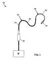
- the catheter system 20comprises an elongate catheter assembly 22 having a proximal portion 24 , a middle portion 26 and a distal portion 28 .
- the distal portion 28includes a steering section 32 and an end effector 34 .
- the catheter assembly 22can include elongate internal components that extend through the proximal, middle and distal portions 22 , 24 and 26 , such as fiber optics, power leads, instrumentation leads, a pull wire and an irrigation lumen.
- the proximal portionis operatively coupled with a handle 36 .
- the handle 36may be operatively coupled with various appurtenances 38 to augment the operation of the catheter system 20 .
- Non-limiting examples of appurtenances 38include power sources and/or irrigation systems for sourcing the end effector 34 , electromagnetic sources for sourcing fiber optic systems within the catheter system 20 , data acquisition devices for monitoring instrumentation of the catheter system 20 , and/or control systems for controlling the sourcing of the end effector 34 .
- a “unitary body”, for purposes of this application,is a body that, in its final form, is a continuous single piece member.
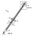
- a tapered steering spine 40is depicted in an embodiment of the invention that can be utilized as the steering section 32 of the distal portion 28 of the elongate catheter assembly 22 .
- a “steering spine”is a steering mechanism that is formed from a unitary body, such as a tube or wire, with the unitary body being slotted or grooved in a way that defines a continuous portion that extends throughout the length of the steering mechanism.
- a “tapered steering spine”is a steering spine that has increasing flexibility from a proximal portion to a distal portion. This shape and flexibility permits the steering spine to be controlled in straight configurations as seen in FIG. 2 as well as in an infinite number of deflected configurations similar to the one depicted in FIG. 5 , for example.
- the tapered steering spine 40comprises a plurality of slots 42 that are formed along a longitudinal axis 44 of a unitary body 46 .
- the plurality of slots 42define a series of axially spaced rings 48 that are integral with a straight spine portion 50 that runs along one side of the tapered steering spine 40 .
- the each slot 42defines a pair of lateral openings 52 a and 52 b and a tongue-and-groove structure 53 that includes a tongue portion 54 and a groove portion 56 .
- the tongue portion 54can be characterized as having a tangential or lateral width 58 and an axial length 60 that extends from a pair of shoulder portions 62 a and 62 b .
- the groove portion 56can be characterized has having an axial depth 66 , a lateral width 68 and as defining a pair of shoulder portions 70 a and 70 b .
- the axial depth 66 of the groove portion 56is of greater dimension than the axial length 60 of the tongue portion 54 .
- a pull wire 72extends into the tapered steering spine 40 .
- the pull wire 72is connected to the distal end of the tapered steering spine 40 and is radially offset so that it is diametrically opposed to the straight spine portion 50 .
- Each of the plurality of slotscan be characterized as having a tangential dimension 78 .
- a “tangential dimension”is an arc length at the outer diameter of the unitary body 46 at a fixed axial location. Accordingly, the tangential dimension 78 appears as a lateral dimension in the unrolled views of FIGS. 7A through 10 .
- the tangential dimensions 78 of the slotsprogressively increase from the proximal to the distal end of the tapered steering spine 40 , as depicted in FIGS. 6 through 10 .
- a proximal end slot 42 ahas a tangential dimension 78 a ( FIG. 8 ) that is less than a tangential dimension 78 b of a distal end slot 42 b ( FIG. 9 ).
- the tangential dimensions 78 of the plurality of slots 42 between slots 42 a and 42 bincrease monotonically (linearly) along the length of the tapered steering spine 40 from proximal to distal.
- a divergence angle 80is defined for linearly increasing tangential dimensions 78 of the plurality of slots 42 from proximal to distal.
- the divergence angle 80is on the order of 0.1°, which is provided as an example only and is not to be construed as limiting.
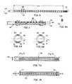
- FIG. 7Bdepicts an unrolled plan view of a tapered steering spine which has been split along a longitudinal axis passing through the tongue and groove portions 54 and 56 of the tapered steering spine (rather than along the continuous straight portion 50 of the spine as depicted in FIG. 7A ).
- the narrowing of the width of the spine from the proximal end to the distal endis depicted in FIG. 7B .
- the width of the straight, continuous portion 50 of the spine at the proximal-most slot 77can be seen to be slightly wider than at the distal-most slot 79 .
- FIGS. 6, 6A and 6BA side view of the tapered steering spine is presented in FIG. 6 , in which a first axis 81 runs through the continuous spine portion 50 such that it is generally parallel to the central longitudinal axis 44 of the spine when in an unflexed state. Further, a second axis 83 is centrally located relative to the tongue and groove structures 53 in a location diametrically opposed to the spine portion 50 and its axis 81 . Based on this arrangement, cross sections are taken of the steering spine 40 at a first location in the proximal-most slot ( FIG. 6A ) and at a second location in the distal-most slot ( FIG. 6B ). Note that the spine portion 50 in FIG. 6A is larger than the spine portion 50 of FIG. 6B due to the increased slot sizes in FIG. 6B . The significance of the resulting change in beam thickness is discussed later in greater detail below.
- an unrolled plan view of one of the plurality of axially spaced rings 48 that define the slots 42 along the length of the tapered steering spine 40is depicted.
- the axial spacing between the rings 48can be uniform, as depicted in the figures.
- the axial spacingcan be varied along the axis as another way to provide variable stiffness along the length of the tapered steering spine 40 .
- the tapered steering spine 40can include a deflecting tab structure 90 for coupling the pull wire 72 ( FIG. 3 ).
- the deflecting tab structure 90can be of a U-shape 94 having legs 96 that are cantilevered from the distal end of the unitary body 46 .
- the U-shape 94defines an inside length 98 of the legs 96 , measured between an anchor datum 100 of the legs and an interior apex 102 of the U-shape 94 .
- a stop portion 104can also be extended from the distal end of the unitary body 46 between the legs 96 and defining a gap 106 between the proximal end of the stop portion 104 and the apex 102 of the U-shape 94 .
- the tapered steering spine 40can also be configured to define a passage 108 through the wall of the unitary body 46 that borders the proximal end of the U-shape 94 .
- the pull wire 72is configured to define a hook portion 110 at the distal end for coupling to the deflecting tab structure 90 .
- the elongated catheter assembly 22can comprise a plurality of laterally flexible regions 136 positioned along the length of the elongated catheter assembly 22 .
- the plurality of laterally flexible regions 136can be positioned in areas that benefit from additional flexibility as the elongated catheter assembly 22 is navigated through the biological lumen.
- an example laterally flexible region 136is depicted in an embodiment of the invention having at least one pair of flexures 140 a and 140 b that are in diametric opposition to each other.
- the flexure 140 ais in line with the spine portion 50 .
- a perpendicular axis 141is defined that passes through both flexures 140 a and 140 b and is perpendicular to the longitudinal axis 44 of the tapered steering spine 40 .
- the flexures 140 a and 140 bprovide axial stiffness to the tapered steering spine 40 .
- the laterally flexible region 136can also define one or more slits 144 , each having a proximal side 145 a and a distal side 145 b and ends defined by the respective flexures 140 a or 140 b.
- the flexible region 136can also include offset flexures 142 a and 142 b (flexure 142 b being hidden from view in FIG. 3A ).
- the offset flexures 142 a and 142 bare also in diametric opposition to each other and are rotationally offset from the flexures 140 a and 140 b .
- the offset flexures 142 a and 142 bare rotationally offset 90° from the flexures 140 a and 140 b to define an offset axis 143 that is substantially orthogonal to both the perpendicular axis 141 and the longitudinal axis 44 of the tapered steering spine 40 .
- a plurality of such flexure pairs 140 a , 140 bare oriented to define a plurality of perpendicular axes 141 , the perpendicular axes 141 being parallel to the steering plane.
- the “steering plane”is defined as the plane in which the tapered steering spine 40 flexes when pulled by the pull wire 72 .
- At least one projection 146can also be formed by the shape of the slit 144 to reduce the effective width of the slit 144 .
- the laterally flexible regions 136are configured generally to provide flexibility in directions lateral to the spine portion 50 .
- the flexures 140 a and 140 bact as hinges about which the tapered steering spine 40 can flex. Multiple flexure pairs can provide multiple points about which the tapered steering spine 40 can flex in a single plane. Inclusion of offset flexure pairs 142 a , 142 b in combination with the flexure pairs 140 a , 140 b enable flexing of the tapered steering spine 40 in multiple directions and planes.
- flexing the tapered steering spine 40 about the perpendicular axis 141 and/or the offset axis 143causes at least one of the slits 144 to decrease in width. If the flexing force is great enough, the proximal and distal sides 145 a and 145 b of a given slit 144 will contact each other, thus restricting further flexing of the tapered steering spine 40 in that direction.
- the projection(s) 146when implemented, serve to limit the extent to which the tapered steering spine 40 rotates about the axes 141 , 143 thereby limiting the extent to which the tapered steering spine 40 can laterally flex.
- This arrangementenables the paired flexures 140 a , 140 b and/or 142 a , 142 b to be of a longer axial length for enhanced flexibility while limiting the rotational displacement of the laterally flexible region 136 to prevent hyperextension of the paired flexures 140 a , 140 b and/or 142 a , 142 b.
- An unpaired flexure 148acts as a hinge that enables the tapered steering spine 40 to flex about an axis 150 substantially perpendicular to the longitudinal axis 44 of the tapered steering spine 40 while providing axial stiffness to the tapered steering spine 40 .
- the unpaired flexure 148can be wider than the counterpart paired flexures 140 to mitigate against fatigue fracture caused by repeated flexing.
- the laterally flexible region 137further comprises slits 152 that are positioned on either side of the unpaired flexure 148 configured to limit the extent to which the tapered steering spine 40 can rotate about the perpendicular axis 150 .
- Each slit 152includes a proximal side 153 a and a distal side 153 b and is adapted to intersect the passage 108 extending at least partly around the U-shape 94 .
- the laterally flexible region 137( FIGS. 3B-3D ) provides flexibility lateral to the spine portion 50 akin to the laterally flexible region(s) 136 , but is configured to accommodate the deflecting tab structure 90 .
- flexing the tapered steering spine 40 about the perpendicular axis 150 in a first directioncauses one of the slits 152 to decrease in width until the proximal and distal sides 153 a and 153 b contact each other, thereby restricting further flexing of the tapered steering spine 40 in that direction ( FIG. 3D ).
- the passage 108can be shaped such that the U-shape 94 is in constant contact with the wall of the unitary body 46 regardless of the angle of deflection about axis 150 .
- the contact between the tip of the U-shape 94 and the passage 108provides axial stiffness under compression and serves to counterbalance the action of the unpaired flexure 148 , thereby restricting bending of the laterally flexible region 137 substantially about the perpendicular axis 150 . That is, the counterbalancing effect of the contact between U-shape 94 and passage 108 militates against spurious rotation about axes other than perpendicular axis 150 .
- the laterally flexible regions 137can comprise at least one projection 154 to reduce the effective width of the deflection tab slit 152 , thereby limiting the extent to which the tapered steering spine 40 rotates about the perpendicular axis 150 .
- This arrangementenables the unpaired flexure 148 a longer axial length for enhanced flexibility while limiting the rotational displacement of the laterally flexible region 137 .
- the tapered steering spine 40may be constructed of any material that provides the necessary radius of deflection without yielding and has a high elastic modulus.
- Example materialsinclude nickel-titanium alloys (e.g., NITINOL), nickel-cobalt alloys (e.g., NIVAFLEX) and spring steel.
- the slots 42can be cut using techniques known in the industry such as laser cutting and electroerosion wire cutting.
- the tapered steering spine 40can be coated with a high lubricity coating such as polytetrafluoroethylene (PTFE), fluorinated ethylene propylene (FEP) and poly(p-xylylene) polymers (PARYLENE). In one embodiment, the coating does not extend over a few millimeters near the proximal and distal ends of the tapered steering spine 40 to provide bonding surfaces for affixing the catheter shaft to the tapered steering spine 40 (discussed below).
- PTFEpolytetrafluoroethylene
- FEPfluorinated ethylene
- a catheter shaft 120is depicted in an embodiment of the invention.
- the catheter shaft 120which defines a longitudinal axis 121 and also defines the outer periphery of the elongate catheter assembly 22 , comprises a flexible tube 122 and a trio of electrodes 124 a , 124 b and 124 c (referred to collectively as the electrodes 124 ) at a distal portion 126 of the catheter shaft 120 .
- Each electrode 124 a , 124 b and 124 cis connected to a respective lead wire 128 a , 128 b and 128 c (referred to collectively as the lead wires 128 ).
- the lead wires 128are insulated and are imbedded in the wall of the catheter shaft 120 , each defining a helical shape within the catheter shaft 120 , as depicted in FIG. 16 for example.
- This type of helical arrangementenables the lead wires 128 to flex when the catheter system flexes without creating unwanted resistance to the flexing and without putting undue strain on the lead wires 128 .
- the lead wires 128comprise a single conductor coated with an electrically insulating enamel coating.
- the lead wires 128can each further comprise a plurality of wire strands braided together to form the lead wire 128 and can also be coated with an electrically insulating enamel coating.
- Each wire strandcan be individually enameled before the wire strands are braided together.
- the wire strands of the lead wires 128can be braided together to form the lead wires 128 before being enameled together.
- the catheter shaft 120comprises an inner liner 130 and an outer layer 132 , with the lead wires 128 being located at the interface therebetween or imbedded in the outer layer 132 .
- a torque braid 134can also be disposed at the interface and is in intimate contact with the insulation of the lead wires 128 .
- the torque braid 134can also be comprised of enameled braid wire, providing an additional barrier against the development of a short between the torque braid 134 and the lead wires 128 .
- wires comprising the torque braidare provided with an enamel coating prior to formation of the torque braid 134 .
- the enamel coatingis applied to the torque braid 134 after braiding.
- the enamel coating for the wires(lead wires 128 or the braid wires for the torque braid 134 ) can comprise, for example, polyimide, polyimide-amide, polyurethane, NYLON or PTFE.
- the inner liner 130 and outer layer 132can be comprised of a PEBAX grade polymer.
- Representative and non-limiting dimensions for the cross-section of the catheter shaft 120is a thickness of 0.06 mm for the inner liner 130 and a thickness of 0.2 mm for the outer layer 132 , providing an inner diameter of approximately 1.8 mm and an outer diameter of approximately 2.3 mm (i.e. 7 French).
- the torque braid 134may comprise flat wire braiding (e.g., 0.001 inch by 0.003 inch wire cross section) or round wire braiding (e.g., 0.0015 inches double round wire) of stainless steel.
- the torque braid 134can extend the entire length of the catheter shaft 120 . Alternatively, the torque braid 134 can extend only along only a portion of the catheter shaft 120 .
- the electrical connection between electrodes 124 and the lead wires 128can be established by a soldering process prior to embedding the lead wires 128 in the catheter shaft 120 .
- the lead wires 128extend laterally from the wall of the catheter shaft 120 near the proximal end of the catheter shaft 120 , as depicted in FIG. 13 .
- the lead wires 128can extend axially out the proximal end of the catheter shaft 120 (not depicted).
- the catheter shaft 120can be designed to have sections of discretely varying stiffness.
- the catheter shaft 120is divided into five sections I, IIA, II, III and IV.
- Section Icomprises a majority of the length of the catheter shaft (in one embodiment about 95% of the length).
- Sections IIA, II, III and IVare all located in the distal portion 28 of the elongate catheter assembly 22 .
- Section Iprovides sufficient stiffness for torquing and pushing the elongate catheter body 22 through biological lumens such as veins and arteries.
- Section IIAprovides a transitional stiffness between the stiffer section I and the plyable section II.
- Section IIsurrounds a majority of the steering section 32 and is therefore preferably plyable to conform to the flexing of the steering section 32 .
- Section IIIsurrounds the transition between the steering section 32 and the end effector 34 , and must be relatively stiff to enable axial and lateral forces to be applied to the catheter shaft 120 without kinking.
- section IVis in consideration of a specific embodiment that employs a force sensor (not depicted) at the distal extremity to limit the force that is shunted by the surrounding material of the catheter shaft 120 , thereby enhancing the sensitivity of the force sensor.
- the torque braid 134can be excluded from the portion of the catheter shaft that surrounds the tapered steering spine 40 (corresponding roughly with sections IIA, II, III and IV).
- An advantage of eliminating the torque braid 134 from this portion of the catheter shaft 120is that the risk of the torque braid 134 wearing through the insulation of the lead wires 128 and causing a short is eliminated where it is most likely to occur, i.e. in the region of the elongate catheter body 22 that experiences the greatest degree of deflection.
- the proximal end of the pull wire 72can be inserted into the gap 106 and routed through the tapered steering spine 40 until the hook portion 110 catches the apex 102 of the U-shape 94 .
- the hook portion 110may tend to be proud (i.e. protrude radially) relative to the outer diameter of the tapered steering spine 40 .
- the catheter shaft 120can be slid over the tapered steering spine 40 and over the hook portion 110 .
- the catheter shaft 120can be bonded to the tapered steering spine 40 at these locations.
- the deflecting tab structure 90can be dimensioned to readily deflect inward (i.e. toward the longitudinal axis 44 of the tapered steering spine 40 ) so that the radial reaction force exerted on the catheter shaft is negligible after assembly.
- a “negligible” radial reaction forceis one that does not deform or cause noticeable local bulging of the catheter shaft in the vicinity of the hook portion 110 , thus enabling the tolerance between the catheter shaft and the tapered steering spine to the specified without the need for additional clearance that would otherwise be required to accommodate the presence of the hook.
- a tapered steering spine 40constructed of NITINOL and having a nominal inner diameter of 1.28 mm and a nominal outer diameter of 1.65 mm will not exert a deforming force on the catheter shaft if the length 98 of the legs 96 is approximately 2 mm or greater.
- the material and dimensions provided in this exampleare illustrative only and are not to be construed as limiting.
- the compliance of the tab and attendant depression of the hook portionalso enables a tighter tolerance fit between the tapered steering spine 40 and the catheter shaft 120 .
- the use of the hook portion 110 for distal attachment of the pull wire 72negates the need for a thermal processing step, such as soldering, welding, or providing the pull wire 72 with a wider body at the distal end, such as a ball.
- a thermal processing stepsuch as soldering, welding, or providing the pull wire 72 with a wider body at the distal end, such as a ball.
- Such a thermal-processing of the distal end of the pull wire 72typically causes an local annealing of the pull wire material, resulting in a decrease of the yield strength of the pull wire 72 in the annealed region, initially obtained through strain hardening of the pull wire 72 .
- the loss of yield strength of the pull wire 72can compromise the ability to transmit the tension forces required to achieve maximum tip deflection.
- the stop portion 104prevents the hook portion 110 from sliding off the U-shape 94 when tension is released from the pull wire 72 .
- the passage 108enables the hook portion to have a length that extends beyond the U-shape 94 without hanging up on the unitary body 46 when the deflecting tab structure 90 is deflected radially inward.
- the high lubricity coatingreduces the influence of the catheter shaft 120 on the bending shape of the tapered steering spine 40 by reducing friction losses and enabling relative motion (delamination) between the outer diameter of the tapered steering spine 40 and the inner diameter of the catheter shaft 120 .
- the relative motioncan be substantial during the flexing process because the tapered steering spine 40 and the catheter shaft 120 flex about different neutral planes that are offset with respect to each other.
- the neutral plane of the tapered steering spine 40is substantially along the mid-thickness of the straight spine portion 50 , while the neutral plane of the catheter shaft 120 deforms substantially along the longitudinal axis 121 .
- the high lubricity coatingalso reduces friction between the tapered steering spine 40 and elongate internal components that may come in contact therewith when the tapered steering spine 40 is flexed, such as the pull wire 72 , wiring/cabling such as fiber optics, power leads and instrumentation leads (not depicted) and irrigation lumen (not depicted).
- the tongue-and-groove structures 53can be dimensioned to engage so as to limit the minimum bend radius of the tapered steering spine 40 ( FIG. 5 ).
- the tongue-and-groove structures 53are dimensioned to provide a close tangential or lateral dimension therebetween such that the tapered steering spine 40 can flex freely in the lateral direction, but engage with each other when the tapered steering spine 40 is rotationally deflected about the longitudinal axis 44 . In this way, the close tangential or lateral tolerance between the tongue-and-groove structures 53 enables the transmission of torque and increases the torsional rigidity of the tapered steering spine 40 over that of the straight spine portion 50 alone.
- the shoulder portions 62 a , 62 b and 70 a , 70 bengage when at the maximum degree of flexing. Engagement of the shoulder portions 62 a , 62 b and 70 a , 70 b provides two lines of contact that are laterally spaced apart, thus providing greater stability than if the tongue portion 54 engaged with the groove portion 56 for only a single line of contact. Engagement of the shoulder and tongue portions can be seen in FIG. 5 , which depicts the tapered steering spine 40 in a deflected orientation. Engagement of the shoulder portions 62 b and tongue portions can be seen as well as the spaces that remain between the tongue portions 54 and groove portions 56 .
- the depiction of FIG. 5also depicts a curvature radius p and a deflection angle ⁇ of the tapered steering spine 40 in a deflected orientation.
- the curvature radius ⁇is defined from the origin of the substantially circular arc defined by the deflected orientation of the tapered steering spine 40 to the centerline (longitudinal axis 44 ) of the tapered steering spine 40 .
- An offset axis 45located on a plane that is offset from but parallel to the steering plane, is identified in FIG. 5 for clarity.
- the deflection angle ⁇is defined from the proximal end of the proximal-most ring to the tip of the end effector 34 .
- the curvature radius ⁇is a function of the deflection angle ⁇ , with the curvature radius ⁇ being inversely proportional to the deflection angle ⁇ .
- a maximum deflection angle ⁇ max and a minimum curvature radius ⁇ minare established by the clearance between the contacting portions of the rings 48 . That is, for embodiments where the shoulder portions 62 a , 62 b and 70 a , 70 b provide the lines of contact, the maximum deflection angle ⁇ max and the minimum curvature radius ⁇ min are determined by the clearance between 62 a , 62 b and 70 a , 70 b . For embodiments where the tongue and groove portions 54 and 56 are brought into contact, the maximum deflection angle ⁇ max and the minimum curvature radius ⁇ min are determined by the clearance between the tongue and groove portions 54 and 56 .
- a deflection angle ⁇ of 235°would cause the distal tip of the end effector 34 to touch the longitudinal axis 44 as projected from the proximal end of the tapered steering spine 40 .
- the maximum deflection angle ⁇ maxis something less than 235° because of the finite thickness or diameter of the catheter assembly 22 that passes along the longitudinal axis 44 .
- the maximum deflection angle ⁇ maxis approximately 225°. In other embodiments, the maximum deflection angle ⁇ max is approximately 180°.
- the tapered steering spine 40is designed to produce a minimum bend radius of 10 mm.
- tongue and groove portions 54 and 56 of the tapered steering spine 40 as depictedprovides the rotational stiffness regardless of the degree of lateral bending. That is, the tongue and groove portions 54 and 56 will engage each other under rotational flexing whether the tapered steering spine 40 is in a straight orientation, at the maximum degree of flexing (minimum bend radius), or anywhere in between.
- the resilience of the straight spine portion 50provides a restoring force that enables control of the bend radius and substantially restores the tapered steering spine 40 to a straight shape.
- the increasing tangential dimensions 78 of the plurality of slots 42 from proximal to distalprovides the variable stiffness of the tapered steering spine 40 , with the stiffness decreasing from proximal to distal.
- the decreasing stiffnesscompensates for friction losses between the pull wire 72 and the tapered steering spine 40 .
- the friction between the pull wire and the inner diameter of the tapered steering spine 40increasingly reduces the force transmitted by the pull wire from the proximal to the distal end of the steering device.
- the local bending moment M B (x)is likewise reduced, resulting in an increase of the local radius of curvature from proximal to distal.
- the angle of the spine deflection subjected to local bendingis expected to scale linearly with the first derivative the deflection, v′(x).
- the inverse value of the curvature radius ⁇is proportional to the second derivative of the spine deflection (v′′(x)), which is linearly proportional with the bending moment of inertia Iz (Eq. 1).
- the beam thickness hcan be a constant value, or can vary along the spine axial coordinate following a given function h(x). If M B (x) decreases with x as a consequence of the pullwire friction, the local radius of curvature ⁇ typically increases for a constant beam thickness h. Under such circumstances, h(x) can be correspondingly decreased to compensate for the decreasing M B (x) and improve the uniformity of the radius of curvature ⁇ along the structure.
- h 0represents the initial beam thickness of the proximal location of the continuous spine 50
- h(x)represents beam thickness at a more distal location on the spine.
- the initial beam thickness h 0is greater than the beam thickness h(x) because of the tangential dimension of the continuous spine 50 is greater at the proximal end than at the more distal location of h(x).
- the formulationscan be used to compensate for the pull wire frictional loss to achieve a more uniform bend radius along the length of the tapered steering spine 40 .
- the bending shape of a non-tapered spine 112 having a flexible beam of constant thicknesswas evaluated under pull wire tension to establish the effect of friction losses.
- a tension forcewas applied to the pull wire, causing the non-tapered spine to flex.
- the local radii of curvature ⁇were then measured at different axial locations A, B, C and D, each located at a unique axial distance x referenced from the proximal end of the non-tapered steering spine 112 .
- the local radii of curvature ⁇ corresponding to locations A, B, C and Dare designated ⁇ A, ⁇ B, ⁇ C and ⁇ D, respectively, in FIG. 11 .
- the resultsare tabulated in Table 1 and graphed in FIG. 12 . Results indicate an increasing radius of curvature towards the distal end (high x values), as a consequence of the frictional losses to force exerted by the pull wire force loss.
- h 00.35 mm
- L50 mm
- ⁇ hwas established at 0.12 mm to provide a more uniform local bending radius ⁇ as per Eq. (3).
- a resulting adjusted radius parameter ⁇ adjustedis given in Table 1 and graphed in FIG. 12 .
- the precedingis based on a beam thickness that decreases linearly along the tapered steering spine 40 .
- a non-linear beam thickness dependencycan also be utilized to improve on the uniformity of the local radii of curvature.
- Other effects on the bending radii, such as the catheter shaft and friction between the spine and shaft,can also be added to the experimental set up, but using substantially the same technique.
- the curve fit parameter(e.g., ⁇ h in the example above) can be determined iteratively or by least-squares line fitting techniques.
- a method for determining the tapering of a steering spineis as follows:
- the “beam thickness” of the tapered steering spine 40corresponds only to the sections of the straight spine portion 50 that are between the rings 48 . Accordingly, when the beam thickness is herein referred to as being “linear” or “non-linear,” only the profile of the beam exclusive of the rings 48 are being described.
Landscapes
- Health & Medical Sciences (AREA)
- Life Sciences & Earth Sciences (AREA)
- Engineering & Computer Science (AREA)
- Biomedical Technology (AREA)
- Pulmonology (AREA)
- Anesthesiology (AREA)
- Biophysics (AREA)
- Heart & Thoracic Surgery (AREA)
- Hematology (AREA)
- Animal Behavior & Ethology (AREA)
- General Health & Medical Sciences (AREA)
- Public Health (AREA)
- Veterinary Medicine (AREA)
- Mechanical Engineering (AREA)
- Media Introduction/Drainage Providing Device (AREA)
Abstract
Description
where E is the modulus of elasticity of the steering spine material. The bending moment of inertia Iz in turn scales with h3, where h represents the beam thickness:
Iz˜h3 Eq. (2)
Solving for the curvature radius ρ yields:
h(x)=h0−(Δh/L)x Eq. (4)
where 0<x<L, Δh is the change in beam thickness over a representative length L of the portion to be tapered. Because the bending radius of a beam is believed to be substantially proportional the beam thickness cubed (h3, Eq. (2)), a local curvature radius correction factor is derived:
(h(x)/h0)3 Eq. (5)
where h(x) is given in Eq. (4) and the constant beam thickness h0is the maximum beam thickness at the proximal end of the tapered beam portion.
tan−1(Δh/L)=tan−1(0.12/50)=0.14° Eq. (6)
| TABLE 1 | |||||
| ρadjusted[mm] = | |||||
| ρ(x)[h(x)/h0]3 | |||||
| ρ(x) | where | ||||
| Location | x [mm] | [mm] | h(x) = h0− (Δh/Ltot)x | ||
| A | 5.7 | 10.0 | 10 | ||
| B | 15.2 | 17.6 | 14.4 | ||
| C | 22.8 | 20.8 | 14.3 | ||
| D | 43.7 | 27.9 | 11.2 | ||
- providing an non-tapered steering spine having a proximal end and a distal end and defining a longitudinal axis, the non-tapered steering spine including a plurality of axially spaced rings that define a plurality of slots therebetween, each of the rings being substantially identical and each of the slots being substantially identical, the non-tapered steering spine having a constant beam thickness h0and having a total axial length LTOTdefined between the proximal boundary of a proximal-most of the plurality of slots and a distal boundary of a distal-most of the plurality of slots.
- providing a pull wire for actuation of the non-tapered steering spine
- applying a tension force to the pull wire so that the non-tapered steering spine is maintained in a deflected state.
- measuring a plurality of local radii of curvature ρ(x) of the non-tapered steering spine in the deflected state at known locations x, each of the plurality of local radii of curvature ρ(x) being measured at a respective location x along the longitudinal axis of the non-tapered steering spine, wherein x is measured from the proximal boundary of the proximal-most of the plurality of slots.
- calculating an adjusted local radii of curvature ρa(x) according to Eq. (4).
- repeating the step of calculating for different values of Δh/L until the adjusted local radii of curvature ρa(x) is uniform to within a desired tolerance.
Claims (19)
Priority Applications (1)
| Application Number | Priority Date | Filing Date | Title |
|---|---|---|---|
| US13/084,155US9795765B2 (en) | 2010-04-09 | 2011-04-11 | Variable stiffness steering mechanism for catheters |
Applications Claiming Priority (3)
| Application Number | Priority Date | Filing Date | Title |
|---|---|---|---|
| US32262710P | 2010-04-09 | 2010-04-09 | |
| US201061424445P | 2010-12-17 | 2010-12-17 | |
| US13/084,155US9795765B2 (en) | 2010-04-09 | 2011-04-11 | Variable stiffness steering mechanism for catheters |
Publications (2)
| Publication Number | Publication Date |
|---|---|
| US20110251519A1 US20110251519A1 (en) | 2011-10-13 |
| US9795765B2true US9795765B2 (en) | 2017-10-24 |
Family
ID=44761442
Family Applications (1)
| Application Number | Title | Priority Date | Filing Date |
|---|---|---|---|
| US13/084,155Active2033-04-05US9795765B2 (en) | 2010-04-09 | 2011-04-11 | Variable stiffness steering mechanism for catheters |
Country Status (1)
| Country | Link |
|---|---|
| US (1) | US9795765B2 (en) |
Cited By (11)
| Publication number | Priority date | Publication date | Assignee | Title |
|---|---|---|---|---|
| US20130225943A1 (en)* | 2012-02-22 | 2013-08-29 | Veran Medical Technologies, Inc. | Steerable surgical catheter having biopsy devices and related systems and methods for four dimensional soft tissue navigation |
| US20150165558A1 (en)* | 2012-05-30 | 2015-06-18 | Admedes Schuessler Gmbh | Method for producing a body implant, assembly consisting of a guide wire and a body implant, and a medical instrument |
| US20170035567A1 (en)* | 2015-08-07 | 2017-02-09 | Medtronic Vascular, Inc. | System and method for deflecting a delivery catheter |
| US10327933B2 (en)* | 2015-04-28 | 2019-06-25 | Cook Medical Technologies Llc | Medical cannulae, delivery systems and methods |
| WO2020221664A1 (en) | 2019-04-30 | 2020-11-05 | Biotronik Ag | Flexible elongated tube for a catheter system |
| US11213309B2 (en) | 2019-05-23 | 2022-01-04 | Biosense Webster (Israel) Ltd. | Medical probe having improved maneuverability |
| US11266303B2 (en)* | 2013-09-26 | 2022-03-08 | Gyrus Acmi, Inc. | Oblong endoscope sheath |
| US11517319B2 (en) | 2017-09-23 | 2022-12-06 | Universität Zürich | Medical occluder device |
| US11944315B2 (en) | 2019-09-26 | 2024-04-02 | Universität Zürich | Left atrial appendage occlusion devices |
| USD1039141S1 (en) | 2020-04-27 | 2024-08-13 | Acclarent, Inc. | Flex section in shaft for ENT instrument |
| US12402885B2 (en) | 2017-09-23 | 2025-09-02 | Universität Zürich | Medical occlusion device |
Families Citing this family (84)
| Publication number | Priority date | Publication date | Assignee | Title |
|---|---|---|---|---|
| US12220538B2 (en) | 2008-12-08 | 2025-02-11 | Scientia Vascular, Inc. | Micro-fabricated intravascular devices having varying diameters |
| US11406791B2 (en) | 2009-04-03 | 2022-08-09 | Scientia Vascular, Inc. | Micro-fabricated guidewire devices having varying diameters |
| US8504139B2 (en) | 2009-03-10 | 2013-08-06 | Medtronic Xomed, Inc. | Navigating a surgical instrument |
| US9226688B2 (en) | 2009-03-10 | 2016-01-05 | Medtronic Xomed, Inc. | Flexible circuit assemblies |
| US9226689B2 (en) | 2009-03-10 | 2016-01-05 | Medtronic Xomed, Inc. | Flexible circuit sheet |
| US9339264B2 (en)* | 2010-10-01 | 2016-05-17 | Cook Medical Technologies Llc | Port access visualization platform |
| US8906013B2 (en) | 2010-04-09 | 2014-12-09 | Endosense Sa | Control handle for a contact force ablation catheter |
| KR101478264B1 (en)* | 2010-04-30 | 2014-12-31 | 메드트로닉 좀드 인코퍼레이티드 | Navigated malleable surgical instrument |
| US9974501B2 (en) | 2011-01-28 | 2018-05-22 | Medtronic Navigation, Inc. | Method and apparatus for image-based navigation |
| US10617374B2 (en) | 2011-01-28 | 2020-04-14 | Medtronic Navigation, Inc. | Method and apparatus for image-based navigation |
| US10492868B2 (en) | 2011-01-28 | 2019-12-03 | Medtronic Navigation, Inc. | Method and apparatus for image-based navigation |
| EP2677961B1 (en) | 2011-02-24 | 2024-12-11 | Eximo Medical Ltd. | Hybrid catheter for vascular intervention |
| US20140107623A1 (en)* | 2012-09-11 | 2014-04-17 | Amr Salahieh | Steerable Delivery Sheaths |
| US9162046B2 (en) | 2011-10-18 | 2015-10-20 | Boston Scientific Scimed, Inc. | Deflectable medical devices |
| US9750486B2 (en) | 2011-10-25 | 2017-09-05 | Medtronic Navigation, Inc. | Trackable biopsy needle |
| US9216056B2 (en) | 2012-03-02 | 2015-12-22 | Biosense Webster (Israel) Ltd. | Catheter for treatment of atrial flutter having single action dual deflection mechanism |
| WO2014074876A1 (en)* | 2012-11-09 | 2014-05-15 | Cardiac Pacemakers, Inc. | Implantable lead having a lumen with a wear-resistant liner |
| US9549666B2 (en) | 2012-11-10 | 2017-01-24 | Curvo Medical, Inc. | Coaxial micro-endoscope |
| US9233225B2 (en) | 2012-11-10 | 2016-01-12 | Curvo Medical, Inc. | Coaxial bi-directional catheter |
| CN104902801B (en)* | 2013-01-07 | 2018-10-09 | 安布股份有限公司 | Hinged end pieces for endoscopes |
| WO2014163601A1 (en)* | 2013-03-11 | 2014-10-09 | Lightlab Imaging, Inc. | Friction torque limiter for an imaging catheter |
| US9174024B1 (en) | 2013-03-15 | 2015-11-03 | St. Jude Medical Luxembourg Holdings S.À.R.L. | Steering control mechanisms for catheters |
| ES2774327T3 (en) | 2013-03-15 | 2020-07-20 | Qxmedical Llc | Reinforcement catheter |
| US10278729B2 (en) | 2013-04-26 | 2019-05-07 | Medtronic Xomed, Inc. | Medical device and its construction |
| EP2990071B1 (en)* | 2013-04-26 | 2020-01-22 | Terumo Kabushiki Kaisha | Medical elongated body |
| US9855404B2 (en) | 2013-05-03 | 2018-01-02 | St. Jude Medical International Holding S.À R.L. | Dual bend radii steering catheter |
| WO2015042453A1 (en) | 2013-09-20 | 2015-03-26 | Canon U.S.A., Inc. | Control apparatus for tendon-driven device |
| EP3139989A4 (en)* | 2014-05-08 | 2017-05-17 | Eximo Medical Ltd. | Methods for deflecting catheters |
| WO2016056417A1 (en)* | 2014-10-06 | 2016-04-14 | オリンパス株式会社 | Endoscope |
| GB2532044A (en) | 2014-11-06 | 2016-05-11 | Phagenesis Ltd | Catheter for recovery of dysphagia |
| JP5874885B1 (en)* | 2015-02-24 | 2016-03-02 | 株式会社エフエムディ | Medical guidewire |
| US10420537B2 (en) | 2015-03-27 | 2019-09-24 | Shifamed Holdings, Llc | Steerable medical devices, systems, and methods of use |
| US10675057B2 (en) | 2015-04-28 | 2020-06-09 | Cook Medical Technologies Llc | Variable stiffness cannulae and associated delivery systems and methods |
| JP6476293B2 (en)* | 2015-06-12 | 2019-02-27 | オリンパス株式会社 | Flexible tube insertion device |
| CN107072489B (en)* | 2015-07-21 | 2019-12-10 | 奥林巴斯株式会社 | Endoscope with a detachable handle |
| GB201513989D0 (en) | 2015-08-07 | 2015-09-23 | Phagenesis Ltd | Method of diagnosis of dysphagia |
| WO2017053663A1 (en)* | 2015-09-23 | 2017-03-30 | Medtronic Vascular Inc. | Guide extension catheter with perfusion openings |
| US11986607B2 (en) | 2015-10-01 | 2024-05-21 | Qxmedical, Llc | Catheter structure with improved support and related systems, methods, and devices |
| WO2017066253A1 (en) | 2015-10-15 | 2017-04-20 | Canon U.S.A., Inc. | Steerable medical instrument |
| JP6697291B2 (en)* | 2016-03-11 | 2020-05-20 | オリンパス株式会社 | Endoscope bending tube |
| EP3442651B1 (en)* | 2016-04-15 | 2022-04-13 | Medtronic, Inc. | Medical device lead assembly with variable pitch coil |
| CN109414292A (en) | 2016-05-05 | 2019-03-01 | 爱克斯莫医疗有限公司 | Device and method for cutting off and/or melting unwanted tissue |
| US10555756B2 (en) | 2016-06-27 | 2020-02-11 | Cook Medical Technologies Llc | Medical devices having coaxial cannulae |
| US11207502B2 (en) | 2016-07-18 | 2021-12-28 | Scientia Vascular, Llc | Guidewire devices having shapeable tips and bypass cuts |
| US11052228B2 (en) | 2016-07-18 | 2021-07-06 | Scientia Vascular, Llc | Guidewire devices having shapeable tips and bypass cuts |
| US10646689B2 (en) | 2016-07-29 | 2020-05-12 | Cephea Valve Technologies, Inc. | Mechanical interlock for catheters |
| US10729886B2 (en) | 2016-08-24 | 2020-08-04 | Intuitive Surgical Operations, Inc. | Axial support structure for a flexible elongate device |
| US10682192B2 (en)* | 2016-09-30 | 2020-06-16 | Intuitive Surgical Operations, Inc. | Variable-length guide apparatus for delivery of a flexible instrument and methods of use |
| US11452541B2 (en) | 2016-12-22 | 2022-09-27 | Scientia Vascular, Inc. | Intravascular device having a selectively deflectable tip |
| WO2018172565A1 (en) | 2017-03-24 | 2018-09-27 | Ambu A/S | Articulated tip part for an endoscope |
| US10933214B2 (en)* | 2017-04-26 | 2021-03-02 | Biosense Webster (Israel) Ltd. | Method for producing a deflectable insertion tool |
| US11376401B2 (en)* | 2017-04-26 | 2022-07-05 | Acclarent, Inc. | Deflectable guide for medical instrument |
| US11007347B2 (en)* | 2017-04-26 | 2021-05-18 | Biosense Webster (Israel) Ltd. | Deflectable insertion tool |
| US12178662B2 (en)* | 2017-05-23 | 2024-12-31 | Boston Scientific Scimed, Inc. | Catheter and spring element for contact force sensing |
| ES2966345T3 (en) | 2017-05-26 | 2024-04-22 | Scientia Vascular Inc | Microfabricated medical device with a non-helical cutting arrangement |
| WO2019002186A1 (en) | 2017-06-26 | 2019-01-03 | Ambu A/S | A bending section for an endoscope |
| WO2019018736A2 (en)* | 2017-07-21 | 2019-01-24 | Intuitive Surgical Operations, Inc. | Flexible elongate device systems and methods |
| US10918268B2 (en)* | 2017-08-29 | 2021-02-16 | Opcom Inc. | Insert tube and endoscope using the same |
| CN107802229A (en)* | 2017-09-21 | 2018-03-16 | 华中科技大学鄂州工业技术研究院 | A kind of swan-neck of endoscope |
| CN107811600A (en)* | 2017-10-20 | 2018-03-20 | 上海安清医疗器械有限公司 | The soft or hard swan-neck of multisection type gradual change, endoscope-use insertion tube and endoscope using the swan-neck |
| CN111629777B (en) | 2017-11-30 | 2024-09-03 | 领先仿生公司 | Slotted stiffening member that facilitates insertion of electrode lead into cochlea of patient |
| US11033714B2 (en)* | 2017-12-15 | 2021-06-15 | Biosense Webster (Israel) Ltd. | Catheter with biased and discrete deflection characteristics and related methods |
| US11305095B2 (en) | 2018-02-22 | 2022-04-19 | Scientia Vascular, Llc | Microfabricated catheter having an intermediate preferred bending section |
| US11529038B2 (en)* | 2018-10-02 | 2022-12-20 | Elements Endoscopy, Inc. | Endoscope with inertial measurement units and / or haptic input controls |
| CN109349984A (en)* | 2018-11-09 | 2019-02-19 | 苏州新光维医疗科技有限公司 | A flexible gradient endoscope catheter with braided wire structure |
| US12349869B2 (en) | 2018-12-21 | 2025-07-08 | Ambu A/S | Articulated tip part for an endoscope |
| EP3669744B1 (en) | 2018-12-21 | 2025-07-09 | Ambu A/S | An articulated tip part for an endoscope |
| US12011555B2 (en) | 2019-01-15 | 2024-06-18 | Scientia Vascular, Inc. | Guidewire with core centering mechanism |
| CN109770833B (en)* | 2019-03-15 | 2024-09-10 | 新光维医疗科技(苏州)股份有限公司 | Endoscope |
| JP7210699B2 (en)* | 2019-03-25 | 2023-01-23 | 日本ライフライン株式会社 | catheter |
| EP3797671A1 (en) | 2019-09-26 | 2021-03-31 | Ambu A/S | A tip part for an endoscope and the manufacture thereof |
| US12178975B2 (en) | 2020-01-23 | 2024-12-31 | Scientia Vascular, Inc. | Guidewire having enlarged, micro-fabricated distal section |
| US12343485B2 (en) | 2020-01-23 | 2025-07-01 | Scientia Vascular, Inc. | High torque guidewire device |
| EP3925512A1 (en) | 2020-06-19 | 2021-12-22 | Ambu A/S | An endoscope comprising an articulated bending section body |
| US12376904B1 (en) | 2020-09-08 | 2025-08-05 | Angiodynamics, Inc. | Dynamic laser stabilization and calibration system |
| US12296112B2 (en) | 2020-10-05 | 2025-05-13 | Scientia Vascular, Inc. | Microfabricated catheter devices with high axial strength |
| EP3988006B1 (en) | 2020-10-20 | 2023-08-09 | Ambu A/S | An endoscope |
| WO2022090802A1 (en) | 2020-10-29 | 2022-05-05 | Incite Medical Sarl | Introducer for oblique vein of marshall |
| EP4240460A4 (en) | 2020-11-09 | 2024-05-08 | Agile Devices, Inc. | CATHETER CONTROL DEVICES |
| US11992681B2 (en) | 2020-11-20 | 2024-05-28 | Phagenesis Limited | Devices, systems, and methods for treating disease using electrical stimulation |
| CN114464357B (en)* | 2022-01-24 | 2023-09-29 | 中国石油化工股份有限公司 | Method for preventing perforation cable of tractor of high-inclination horizontal well from bending |
| CN114534067A (en)* | 2022-02-23 | 2022-05-27 | 南通伊诺精密塑胶导管有限公司 | Controllable guiding directional catheter |
| US12038322B2 (en) | 2022-06-21 | 2024-07-16 | Eximo Medical Ltd. | Devices and methods for testing ablation systems |
| CN115317761B (en)* | 2022-09-13 | 2024-07-19 | 上海普实医疗器械股份有限公司 | Adjustable bend catheter with hypotube |
Citations (178)
| Publication number | Priority date | Publication date | Assignee | Title |
|---|---|---|---|---|
| US2515366A (en) | 1948-05-04 | 1950-07-18 | John A Zublin | Heavy-duty flexible drill pipe |
| US3416531A (en) | 1964-01-02 | 1968-12-17 | Edwards Miles Lowell | Catheter |
| US3557780A (en) | 1967-04-20 | 1971-01-26 | Olympus Optical Co | Mechanism for controlling flexure of endoscope |
| US3572325A (en) | 1968-10-25 | 1971-03-23 | Us Health Education & Welfare | Flexible endoscope having fluid conduits and control |
| US3583393A (en) | 1967-12-26 | 1971-06-08 | Olympus Optical Co | Bendable tube assembly |
| US3700289A (en) | 1970-04-15 | 1972-10-24 | Singer Co | Flexure hinge assembly |
| US3710781A (en) | 1970-10-12 | 1973-01-16 | T Huthcins | Catheter tip pressure transducer |
| US3739770A (en) | 1970-10-09 | 1973-06-19 | Olympus Optical Co | Bendable tube of an endoscope |
| US3799151A (en) | 1970-12-21 | 1974-03-26 | Olympus Optical Co | Controllably bendable tube of an endoscope |
| US3802440A (en) | 1972-12-19 | 1974-04-09 | M Salem | Intubation guide |
| US3905361A (en) | 1974-04-24 | 1975-09-16 | Brunswick Mfg Co Inc | Apparatus for sealing the esophagus and providing artificial respiration and evacuating the stomach |
| US3948255A (en) | 1974-06-06 | 1976-04-06 | Davidson Kenneth L | Apparatus for endotracheal and esophageal intubation |
| US3998216A (en) | 1973-10-04 | 1976-12-21 | Olympus Optical Co., Ltd. | Bending tube for endoscope |
| US4108211A (en) | 1975-04-28 | 1978-08-22 | Fuji Photo Optical Co., Ltd. | Articulated, four-way bendable tube structure |
| US4329980A (en) | 1979-03-06 | 1982-05-18 | Olympus Optical Co., Ltd. | Flexible sheath for an endoscope |
| US4351323A (en) | 1979-10-20 | 1982-09-28 | Kabushiki Kaisha Medos Kenkyusho | Curvable pipe assembly in endoscope |
| US4432349A (en) | 1979-04-03 | 1984-02-21 | Fuji Photo Optical Co., Ltd. | Articulated tube structure for use in an endoscope |
| US4502482A (en) | 1983-05-23 | 1985-03-05 | Deluccia Victor C | Endotracheal tube complex |
| US4516972A (en) | 1982-01-28 | 1985-05-14 | Advanced Cardiovascular Systems, Inc. | Guiding catheter and method of manufacture |
| US4543090A (en) | 1983-10-31 | 1985-09-24 | Mccoy William C | Steerable and aimable catheter |
| US4580551A (en) | 1984-11-02 | 1986-04-08 | Warner-Lambert Technologies, Inc. | Flexible plastic tube for endoscopes and the like |
| US4586923A (en) | 1984-06-25 | 1986-05-06 | Cordis Corporation | Curving tip catheter |
| US4601705A (en) | 1983-10-31 | 1986-07-22 | Mccoy William C | Steerable and aimable catheter |
| US4612927A (en) | 1984-01-12 | 1986-09-23 | Krueger Christian | Instrument for keeping clear the upper respiratory passages |
| US4664113A (en) | 1984-05-30 | 1987-05-12 | Advanced Cardiovascular Systems, Inc. | Steerable dilatation catheter with rotation limiting device |
| US4700693A (en) | 1985-12-09 | 1987-10-20 | Welch Allyn, Inc. | Endoscope steering section |
| US4723936A (en) | 1986-07-22 | 1988-02-09 | Versaflex Delivery Systems Inc. | Steerable catheter |
| US4753223A (en) | 1986-11-07 | 1988-06-28 | Bremer Paul W | System for controlling shape and direction of a catheter, cannula, electrode, endoscope or similar article |
| US4771788A (en) | 1986-07-18 | 1988-09-20 | Pfizer Hospital Products Group, Inc. | Doppler tip wire guide |
| US4834069A (en) | 1987-09-03 | 1989-05-30 | Kabushiki Kaisha Machida Seisakusho | Endoscope with improved inserting portion |
| US4850351A (en) | 1985-05-22 | 1989-07-25 | C. R. Bard, Inc. | Wire guided laser catheter |
| US4874371A (en) | 1987-11-05 | 1989-10-17 | Medilase, Inc. | Control handle |
| US4886067A (en) | 1989-01-03 | 1989-12-12 | C. R. Bard, Inc. | Steerable guidewire with soft adjustable tip |
| US4898577A (en) | 1988-09-28 | 1990-02-06 | Advanced Cardiovascular Systems, Inc. | Guiding cathether with controllable distal tip |
| US4940062A (en) | 1988-05-26 | 1990-07-10 | Advanced Cardiovascular Systems, Inc. | Guiding member with deflectable tip |
| US4960411A (en) | 1984-09-18 | 1990-10-02 | Medtronic Versaflex, Inc. | Low profile sterrable soft-tip catheter |
| US4960410A (en) | 1989-03-31 | 1990-10-02 | Cordis Corporation | Flexible tubular member for catheter construction |
| US4960134A (en) | 1988-11-18 | 1990-10-02 | Webster Wilton W Jr | Steerable catheter |
| US4998916A (en) | 1989-01-09 | 1991-03-12 | Hammerslag Julius G | Steerable medical device |
| US4998923A (en) | 1988-08-11 | 1991-03-12 | Advanced Cardiovascular Systems, Inc. | Steerable dilatation catheter |
| US5030204A (en) | 1988-09-28 | 1991-07-09 | Advanced Cardiovascular Systems, Inc. | Guiding catheter with controllable distal tip |
| US5056517A (en) | 1989-07-24 | 1991-10-15 | Consiglio Nazionale Delle Ricerche | Biomagnetically localizable multipurpose catheter and method for magnetocardiographic guided intracardiac mapping, biopsy and ablation of cardiac arrhythmias |
| US5108368A (en) | 1990-01-04 | 1992-04-28 | Pilot Cardiovascular System, Inc. | Steerable medical device |
| US5114414A (en) | 1984-09-18 | 1992-05-19 | Medtronic, Inc. | Low profile steerable catheter |
| US5125895A (en) | 1986-07-22 | 1992-06-30 | Medtronic Versaflex, Inc. | Steerable catheter |
| US5152744A (en) | 1990-02-07 | 1992-10-06 | Smith & Nephew Dyonics | Surgical instrument |
| US5178129A (en) | 1989-12-28 | 1993-01-12 | Kabushiki Kaisha Machida Seisakusho | Method of producing bending device |
| US5190050A (en) | 1991-11-08 | 1993-03-02 | Electro-Catheter Corporation | Tip deflectable steerable catheter |
| US5228441A (en) | 1991-02-15 | 1993-07-20 | Lundquist Ingemar H | Torquable catheter and method |
| US5242430A (en) | 1991-01-17 | 1993-09-07 | Cordis Corporation | Limited turn handle for catheter |
| US5299562A (en) | 1992-01-18 | 1994-04-05 | Richard Wolf Gmbh | Endoscope having a controllable distal end piece |
| US5304131A (en) | 1991-07-15 | 1994-04-19 | Paskar Larry D | Catheter |
| US5315996A (en) | 1991-02-15 | 1994-05-31 | Lundquist Ingemar H | Torquable catheter and method |
| US5318525A (en) | 1992-04-10 | 1994-06-07 | Medtronic Cardiorhythm | Steerable electrode catheter |
| US5322064A (en) | 1991-02-15 | 1994-06-21 | Lundquist Ingemar H | Torquable catheter and method |
| US5329923A (en) | 1991-02-15 | 1994-07-19 | Lundquist Ingemar H | Torquable catheter |
| US5358479A (en) | 1993-12-06 | 1994-10-25 | Electro-Catheter Corporation | Multiform twistable tip deflectable catheter |
| US5364351A (en) | 1992-11-13 | 1994-11-15 | Ep Technologies, Inc. | Catheter steering mechanism |
| US5368564A (en) | 1992-12-23 | 1994-11-29 | Angeion Corporation | Steerable catheter |
| US5383923A (en) | 1990-10-20 | 1995-01-24 | Webster Laboratories, Inc. | Steerable catheter having puller wire with shape memory |
| US5383852A (en) | 1992-12-04 | 1995-01-24 | C. R. Bard, Inc. | Catheter with independent proximal and distal control |
| US5395327A (en) | 1990-02-02 | 1995-03-07 | Ep Technologies, Inc. | Catheter steering mechanism |
| US5394864A (en) | 1991-10-15 | 1995-03-07 | Asahi Kogaku Kogyo Kabushiki Kaisha | Bendable portion of endoscope |
| US5395328A (en) | 1994-01-19 | 1995-03-07 | Daig Corporation | Steerable catheter tip having an X-shaped lumen |
| US5397304A (en) | 1992-04-10 | 1995-03-14 | Medtronic Cardiorhythm | Shapable handle for steerable electrode catheter |
| US5409000A (en) | 1993-09-14 | 1995-04-25 | Cardiac Pathways Corporation | Endocardial mapping and ablation system utilizing separately controlled steerable ablation catheter with ultrasonic imaging capabilities and method |
| US5431168A (en) | 1993-08-23 | 1995-07-11 | Cordis-Webster, Inc. | Steerable open-lumen catheter |
| US5437288A (en) | 1992-09-04 | 1995-08-01 | Mayo Foundation For Medical Education And Research | Flexible catheter guidewire |
| US5441483A (en) | 1992-11-16 | 1995-08-15 | Avitall; Boaz | Catheter deflection control |
| US5448989A (en) | 1993-02-22 | 1995-09-12 | Richard Wolf Gmbh | Medical instrument shaft capable of positive and non-positive linking of segments |
| US5454787A (en) | 1991-02-15 | 1995-10-03 | Lundquist; Ingemar H. | Torquable tubular assembly and torquable catheter utilizing the same |
| US5462527A (en) | 1993-06-29 | 1995-10-31 | C.R. Bard, Inc. | Actuator for use with steerable catheter |
| US5478330A (en) | 1992-12-01 | 1995-12-26 | Cardiac Pathways Corporation | Steerable catheter with adjustable bend location and/or radius and method |
| US5484407A (en) | 1993-06-24 | 1996-01-16 | Osypka; Peter | Catheter with steerable distal end |
| US5487757A (en) | 1993-07-20 | 1996-01-30 | Medtronic Cardiorhythm | Multicurve deflectable catheter |
| US5545200A (en) | 1993-07-20 | 1996-08-13 | Medtronic Cardiorhythm | Steerable electrophysiology catheter |
| US5562619A (en) | 1993-08-19 | 1996-10-08 | Boston Scientific Corporation | Deflectable catheter |
| US5573520A (en) | 1991-09-05 | 1996-11-12 | Mayo Foundation For Medical Education And Research | Flexible tubular device for use in medical applications |
| US5603697A (en) | 1995-02-14 | 1997-02-18 | Fidus Medical Technology Corporation | Steering mechanism for catheters and methods for making same |
| US5605543A (en) | 1994-03-10 | 1997-02-25 | Schneider (Usa) Inc. | Catheter having shaft of varying stiffness |
| US5611777A (en) | 1993-05-14 | 1997-03-18 | C.R. Bard, Inc. | Steerable electrode catheter |
| US5676653A (en) | 1995-06-27 | 1997-10-14 | Arrow International Investment Corp. | Kink-resistant steerable catheter assembly |
| US5702433A (en) | 1995-06-27 | 1997-12-30 | Arrow International Investment Corp. | Kink-resistant steerable catheter assembly for microwave ablation |
| US5715817A (en) | 1993-06-29 | 1998-02-10 | C.R. Bard, Inc. | Bidirectional steering catheter |
| US5728144A (en) | 1992-04-13 | 1998-03-17 | Ep Technologies, Inc. | Steerable coaxial cable systems for cardiac ablation |
| US5741429A (en) | 1991-09-05 | 1998-04-21 | Cardia Catheter Company | Flexible tubular device for use in medical applications |
| US5749828A (en) | 1995-12-22 | 1998-05-12 | Hewlett-Packard Company | Bending neck for use with invasive medical devices |
| US5779669A (en) | 1996-10-28 | 1998-07-14 | C. R. Bard, Inc. | Steerable catheter with fixed curve |
| US5782828A (en) | 1996-12-11 | 1998-07-21 | Irvine Biomedical, Inc. | Ablation catheter with multiple flexible curves |
| US5782239A (en) | 1992-06-30 | 1998-07-21 | Cordis Webster, Inc. | Unique electrode configurations for cardiovascular electrode catheter with built-in deflection method and central puller wire |
| US5797842A (en) | 1996-10-31 | 1998-08-25 | E.P. Technologies, Inc. | Steerable electrophysiology catheter |
| US5797905A (en) | 1994-08-08 | 1998-08-25 | E. P. Technologies Inc. | Flexible tissue ablation elements for making long lesions |
| US5807241A (en) | 1995-09-22 | 1998-09-15 | Richard Wolf Gmbh | Bendable tube and method for its manufacture |
| US5820591A (en) | 1990-02-02 | 1998-10-13 | E. P. Technologies, Inc. | Assemblies for creating compound curves in distal catheter regions |
| US5824031A (en) | 1996-02-28 | 1998-10-20 | Cardio Source | Apparatus and method for deflecting a tip of a lead or catheter |
| US5833632A (en) | 1995-12-07 | 1998-11-10 | Sarcos, Inc. | Hollow guide wire apparatus catheters |
| US5857046A (en) | 1997-02-12 | 1999-01-05 | The Whitaker Corporation | Strain relief |
| US5882333A (en) | 1994-05-13 | 1999-03-16 | Cardima, Inc. | Catheter with deflectable distal section |
| US5881727A (en) | 1993-10-14 | 1999-03-16 | Ep Technologies, Inc. | Integrated cardiac mapping and ablation probe |
| US5897554A (en) | 1997-03-01 | 1999-04-27 | Irvine Biomedical, Inc. | Steerable catheter having a loop electrode |
| US5897529A (en) | 1997-09-05 | 1999-04-27 | Cordis Webster, Inc. | Steerable deflectable catheter having improved flexibility |
| US5904667A (en) | 1997-03-17 | 1999-05-18 | C.R. Bard, Inc. | Rotatable control mechanism for steerable catheter |
| US5910129A (en) | 1996-12-19 | 1999-06-08 | Ep Technologies, Inc. | Catheter distal assembly with pull wires |
| US5911720A (en) | 1996-11-26 | 1999-06-15 | Ep Technologies, Inc. | Ablation catheter with segmented tip |
| US5916214A (en) | 1995-05-01 | 1999-06-29 | Medtronic Cardiorhythm | Dual curve ablation catheter |
| US5944690A (en) | 1997-03-17 | 1999-08-31 | C.R. Bard, Inc. | Slidable control mechanism for steerable catheter |
| US5967978A (en) | 1993-01-29 | 1999-10-19 | Cardima, Inc. | Intravascular sensing device |
| US6004279A (en) | 1996-01-16 | 1999-12-21 | Boston Scientific Corporation | Medical guidewire |
| US6027863A (en) | 1991-09-05 | 2000-02-22 | Intratherapeutics, Inc. | Method for manufacturing a tubular medical device |
| US6027473A (en) | 1997-09-05 | 2000-02-22 | Cordis Webster, Inc. | Handle for steerable DMR catheter |
| US6033394A (en) | 1997-12-05 | 2000-03-07 | Intratherapeutics, Inc. | Catheter support structure |
| US6048339A (en) | 1998-06-29 | 2000-04-11 | Endius Incorporated | Flexible surgical instruments with suction |
| US6063080A (en) | 1996-05-16 | 2000-05-16 | Cordis Webster, Inc. | Linear catheter ablation system |
| US6096036A (en) | 1998-05-05 | 2000-08-01 | Cardiac Pacemakers, Inc. | Steerable catheter with preformed distal shape and method for use |
| US6107004A (en) | 1991-09-05 | 2000-08-22 | Intra Therapeutics, Inc. | Method for making a tubular stent for use in medical applications |
| US6120520A (en) | 1997-05-27 | 2000-09-19 | Angiotrax, Inc. | Apparatus and methods for stimulating revascularization and/or tissue growth |
| US6171277B1 (en) | 1997-12-01 | 2001-01-09 | Cordis Webster, Inc. | Bi-directional control handle for steerable catheter |
| US6183463B1 (en) | 1997-12-01 | 2001-02-06 | Cordis Webster, Inc. | Bidirectional steerable cathether with bidirectional control handle |
| US6183435B1 (en) | 1999-03-22 | 2001-02-06 | Cordis Webster, Inc. | Multi-directional steerable catheters and control handles |
| US6198974B1 (en) | 1998-08-14 | 2001-03-06 | Cordis Webster, Inc. | Bi-directional steerable catheter |
| US6221070B1 (en) | 1996-10-18 | 2001-04-24 | Irvine Biomedical, Inc. | Steerable ablation catheter system having disposable shaft |
| US6224587B1 (en) | 1999-11-22 | 2001-05-01 | C.R. Bard, Inc. | Steerable catheter |
| US6241728B1 (en) | 1997-12-18 | 2001-06-05 | Medtronic, Inc. | Left atrium ablation catheter and method |
| US6251104B1 (en) | 1995-05-10 | 2001-06-26 | Eclipse Surgical Technologies, Inc. | Guiding catheter system for ablating heart tissue |
| US6254568B1 (en) | 1999-08-10 | 2001-07-03 | Biosense Webster, Inc. | Deflectable catheter with straightening element |
| US6267746B1 (en) | 1999-03-22 | 2001-07-31 | Biosense Webster, Inc. | Multi-directional steerable catheters and control handles |
| US6428489B1 (en) | 1995-12-07 | 2002-08-06 | Precision Vascular Systems, Inc. | Guidewire system |
| US6440088B1 (en) | 1996-05-24 | 2002-08-27 | Precision Vascular Systems, Inc. | Hybrid catheter guide wire apparatus and method |
| US6468260B1 (en) | 1999-05-07 | 2002-10-22 | Biosense Webster, Inc. | Single gear drive bidirectional control handle for steerable catheter |
| US6470205B2 (en) | 2000-03-13 | 2002-10-22 | Siemens Aktiengesellschaft | Medical instrument for insertion into an examination subject, and medical examination/treatment device employing same |
| US6500167B1 (en) | 1997-09-05 | 2002-12-31 | Biosense Webster, Inc. | Omni-directional steerable catheter |
| US6511471B2 (en)* | 2000-12-22 | 2003-01-28 | Biocardia, Inc. | Drug delivery catheters that attach to tissue and methods for their use |
| US6522933B2 (en) | 2001-03-30 | 2003-02-18 | Biosense, Webster, Inc. | Steerable catheter with a control handle having a pulley mechanism |
| US6533783B1 (en) | 1999-07-14 | 2003-03-18 | Biotronik Mess -Und Therapiegeraete Gmbh & Co. Ingenieurbuero Berlin | Catheter |
| US6551271B2 (en) | 2001-04-30 | 2003-04-22 | Biosense Webster, Inc. | Asymmetrical bidirectional steerable catheter |
| US6569114B2 (en) | 2001-08-31 | 2003-05-27 | Biosense Webster, Inc. | Steerable catheter with struts |
| US6571131B1 (en) | 2000-11-10 | 2003-05-27 | Biosense Webster, Inc. | Deflectable catheter with modifiable handle |
| US6582430B2 (en) | 1999-07-07 | 2003-06-24 | Cardiac Pacemakers, Inc. | Ablation catheter manipulation tool and method therefor |
| US6585717B1 (en) | 1999-06-15 | 2003-07-01 | Cryocath Technologies Inc. | Deflection structure |
| US6585718B2 (en) | 2001-05-02 | 2003-07-01 | Cardiac Pacemakers, Inc. | Steerable catheter with shaft support system for resisting axial compressive loads |
| US6641528B2 (en) | 2000-09-08 | 2003-11-04 | Fuji Photo Optical Co., Ltd. | Bending part of endoscope |
| US6758830B1 (en) | 1999-05-11 | 2004-07-06 | Atrionix, Inc. | Catheter positioning system |
| US20040133220A1 (en)* | 2000-01-31 | 2004-07-08 | Randall Lashinski | Adjustable transluminal annuloplasty system |
| US6776765B2 (en) | 2001-08-21 | 2004-08-17 | Synovis Life Technologies, Inc. | Steerable stylet |
| US6783510B1 (en) | 1999-07-08 | 2004-08-31 | C.R. Bard, Inc. | Steerable catheter |
| US6837867B2 (en) | 2001-04-30 | 2005-01-04 | Biosense Webster, Inc. | Steerable catheter with reinforced tip |
| US6866662B2 (en) | 2002-07-23 | 2005-03-15 | Biosense Webster, Inc. | Ablation catheter having stabilizing array |
| US6890329B2 (en) | 1999-06-15 | 2005-05-10 | Cryocath Technologies Inc. | Defined deflection structure |
| US6893436B2 (en) | 2002-01-03 | 2005-05-17 | Afx, Inc. | Ablation instrument having a flexible distal portion |
| US6913594B2 (en) | 2001-12-31 | 2005-07-05 | Biosense Webster, Inc. | Dual-function catheter handle |
| US6926669B1 (en) | 2000-10-10 | 2005-08-09 | Medtronic, Inc. | Heart wall ablation/mapping catheter and method |
| US7008401B2 (en) | 1990-02-02 | 2006-03-07 | Boston Scientific Scimed, Inc. | Assemblies for creating compound curves in distal catheter regions |
| US7099717B2 (en) | 2002-01-03 | 2006-08-29 | Afx Inc. | Catheter having improved steering |
| US7285108B2 (en) | 2004-06-24 | 2007-10-23 | Cryocor, Inc. | Active system for deflecting a distal portion of a catheter into a hoop configuration |
| US7301131B2 (en) | 2000-01-18 | 2007-11-27 | Afx, Inc. | Microwave ablation instrument with flexible antenna assembly and method |
| US7300438B2 (en) | 2001-04-27 | 2007-11-27 | C.R. Bard, Inc. | Electrophysiology catheter for mapping and/or ablation |
| US7331958B2 (en) | 2001-04-27 | 2008-02-19 | C.R. Bard, Inc. | Handle design for a medical catheter |
| US7344543B2 (en) | 2003-07-01 | 2008-03-18 | Medtronic, Inc. | Method and apparatus for epicardial left atrial appendage isolation in patients with atrial fibrillation |
| US7371232B2 (en) | 2002-02-28 | 2008-05-13 | Biosense Webster, Inc. | Catheter having circular ablation assembly |
| US7387626B2 (en) | 1992-08-12 | 2008-06-17 | Medtronic Vidamed, Inc. | Medical probe device and method |
| US7387630B2 (en) | 2003-10-24 | 2008-06-17 | Biosense Webster, Inc. | Catheter with ablation needle and mapping assembly |
| US7402151B2 (en) | 2004-12-17 | 2008-07-22 | Biocardia, Inc. | Steerable guide catheters and methods for their use |
| US7415300B2 (en) | 2002-05-13 | 2008-08-19 | Cathrx Ltd. | Multi-electrode lead |
| US20080306467A1 (en)* | 2005-02-03 | 2008-12-11 | Boris Reydel | Method and Devices for Selective Endoscopic Retrograde Cholangiopancreatography |
| US7465300B2 (en) | 1999-12-09 | 2008-12-16 | Cryocath Technologies Inc. | Catheter with cryogenic and electrical heating ablation |
| US20090018565A1 (en)* | 2006-06-30 | 2009-01-15 | Artheromed, Inc. | Atherectomy devices, systems, and methods |
| US20090036833A1 (en)* | 2007-08-02 | 2009-02-05 | Boston Scientific Scimed, Inc. | Composite elongate medical device including distal tubular member |
| US20090043283A1 (en)* | 2007-08-07 | 2009-02-12 | Boston Scientific Scimed, Inc. | Microfabricated catheter with improved bonding structure |
| US20090062871A1 (en)* | 2007-08-27 | 2009-03-05 | Singfatt Chin | Balloon cannula system for accessing and visualizing spine and related methods |
| US7524301B2 (en) | 2000-11-29 | 2009-04-28 | C.R. Bard, Inc. | Active counterforce handle for use in bidirectional deflectable tip instruments |
| US20090182416A1 (en)* | 2006-06-20 | 2009-07-16 | Aortx, Inc. | Torque shaft and torque shaft drive |
| USD599904S1 (en) | 2006-08-01 | 2009-09-08 | Cathrx Ltd | Catheter sheath |
| US7625617B1 (en) | 2000-10-20 | 2009-12-01 | Cathrx Ltd | Electrical lead |
| US20100152574A1 (en) | 2007-05-01 | 2010-06-17 | Erdman Arthur G | Coupler assembly for catheters |
| US20100174269A1 (en)* | 2008-07-15 | 2010-07-08 | Penumbra, Inc. | Embolic coil implant system and implantation method |
| US7824345B2 (en) | 2003-12-22 | 2010-11-02 | Boston Scientific Scimed, Inc. | Medical device with push force limiter |
| US7881769B2 (en) | 2002-11-18 | 2011-02-01 | Mediguide Ltd. | Method and system for mounting an MPS sensor on a catheter |
| US7914466B2 (en) | 1995-12-07 | 2011-03-29 | Precision Vascular Systems, Inc. | Medical device with collapse-resistant liner and method of making same |
- 2011
- 2011-04-11USUS13/084,155patent/US9795765B2/enactiveActive
Patent Citations (194)
| Publication number | Priority date | Publication date | Assignee | Title |
|---|---|---|---|---|
| US2515366A (en) | 1948-05-04 | 1950-07-18 | John A Zublin | Heavy-duty flexible drill pipe |
| US3416531A (en) | 1964-01-02 | 1968-12-17 | Edwards Miles Lowell | Catheter |
| US3557780A (en) | 1967-04-20 | 1971-01-26 | Olympus Optical Co | Mechanism for controlling flexure of endoscope |
| US3583393A (en) | 1967-12-26 | 1971-06-08 | Olympus Optical Co | Bendable tube assembly |
| US3572325A (en) | 1968-10-25 | 1971-03-23 | Us Health Education & Welfare | Flexible endoscope having fluid conduits and control |
| US3700289A (en) | 1970-04-15 | 1972-10-24 | Singer Co | Flexure hinge assembly |
| US3739770A (en) | 1970-10-09 | 1973-06-19 | Olympus Optical Co | Bendable tube of an endoscope |
| US3710781A (en) | 1970-10-12 | 1973-01-16 | T Huthcins | Catheter tip pressure transducer |
| US3799151A (en) | 1970-12-21 | 1974-03-26 | Olympus Optical Co | Controllably bendable tube of an endoscope |
| US3802440A (en) | 1972-12-19 | 1974-04-09 | M Salem | Intubation guide |
| US3998216A (en) | 1973-10-04 | 1976-12-21 | Olympus Optical Co., Ltd. | Bending tube for endoscope |
| US3905361A (en) | 1974-04-24 | 1975-09-16 | Brunswick Mfg Co Inc | Apparatus for sealing the esophagus and providing artificial respiration and evacuating the stomach |
| US3948255A (en) | 1974-06-06 | 1976-04-06 | Davidson Kenneth L | Apparatus for endotracheal and esophageal intubation |
| US4108211A (en) | 1975-04-28 | 1978-08-22 | Fuji Photo Optical Co., Ltd. | Articulated, four-way bendable tube structure |
| US4329980A (en) | 1979-03-06 | 1982-05-18 | Olympus Optical Co., Ltd. | Flexible sheath for an endoscope |
| US4432349A (en) | 1979-04-03 | 1984-02-21 | Fuji Photo Optical Co., Ltd. | Articulated tube structure for use in an endoscope |
| US4351323A (en) | 1979-10-20 | 1982-09-28 | Kabushiki Kaisha Medos Kenkyusho | Curvable pipe assembly in endoscope |
| US4516972A (en) | 1982-01-28 | 1985-05-14 | Advanced Cardiovascular Systems, Inc. | Guiding catheter and method of manufacture |
| US4502482A (en) | 1983-05-23 | 1985-03-05 | Deluccia Victor C | Endotracheal tube complex |
| US4601705A (en) | 1983-10-31 | 1986-07-22 | Mccoy William C | Steerable and aimable catheter |
| US4543090A (en) | 1983-10-31 | 1985-09-24 | Mccoy William C | Steerable and aimable catheter |
| US4612927A (en) | 1984-01-12 | 1986-09-23 | Krueger Christian | Instrument for keeping clear the upper respiratory passages |
| US4664113A (en) | 1984-05-30 | 1987-05-12 | Advanced Cardiovascular Systems, Inc. | Steerable dilatation catheter with rotation limiting device |
| US4586923A (en) | 1984-06-25 | 1986-05-06 | Cordis Corporation | Curving tip catheter |
| US5114414A (en) | 1984-09-18 | 1992-05-19 | Medtronic, Inc. | Low profile steerable catheter |
| US4960411A (en) | 1984-09-18 | 1990-10-02 | Medtronic Versaflex, Inc. | Low profile sterrable soft-tip catheter |
| US4580551A (en) | 1984-11-02 | 1986-04-08 | Warner-Lambert Technologies, Inc. | Flexible plastic tube for endoscopes and the like |
| US4850351A (en) | 1985-05-22 | 1989-07-25 | C. R. Bard, Inc. | Wire guided laser catheter |
| US4700693A (en) | 1985-12-09 | 1987-10-20 | Welch Allyn, Inc. | Endoscope steering section |
| US4771788A (en) | 1986-07-18 | 1988-09-20 | Pfizer Hospital Products Group, Inc. | Doppler tip wire guide |
| US4723936A (en) | 1986-07-22 | 1988-02-09 | Versaflex Delivery Systems Inc. | Steerable catheter |
| US5125895A (en) | 1986-07-22 | 1992-06-30 | Medtronic Versaflex, Inc. | Steerable catheter |
| US4753223A (en) | 1986-11-07 | 1988-06-28 | Bremer Paul W | System for controlling shape and direction of a catheter, cannula, electrode, endoscope or similar article |
| US4834069A (en) | 1987-09-03 | 1989-05-30 | Kabushiki Kaisha Machida Seisakusho | Endoscope with improved inserting portion |
| US4874371A (en) | 1987-11-05 | 1989-10-17 | Medilase, Inc. | Control handle |
| US4940062A (en) | 1988-05-26 | 1990-07-10 | Advanced Cardiovascular Systems, Inc. | Guiding member with deflectable tip |
| US4998923A (en) | 1988-08-11 | 1991-03-12 | Advanced Cardiovascular Systems, Inc. | Steerable dilatation catheter |
| US4898577A (en) | 1988-09-28 | 1990-02-06 | Advanced Cardiovascular Systems, Inc. | Guiding cathether with controllable distal tip |
| US5030204A (en) | 1988-09-28 | 1991-07-09 | Advanced Cardiovascular Systems, Inc. | Guiding catheter with controllable distal tip |
| US4960134A (en) | 1988-11-18 | 1990-10-02 | Webster Wilton W Jr | Steerable catheter |
| US4886067A (en) | 1989-01-03 | 1989-12-12 | C. R. Bard, Inc. | Steerable guidewire with soft adjustable tip |
| US4998916A (en) | 1989-01-09 | 1991-03-12 | Hammerslag Julius G | Steerable medical device |
| US4960410A (en) | 1989-03-31 | 1990-10-02 | Cordis Corporation | Flexible tubular member for catheter construction |
| US5056517A (en) | 1989-07-24 | 1991-10-15 | Consiglio Nazionale Delle Ricerche | Biomagnetically localizable multipurpose catheter and method for magnetocardiographic guided intracardiac mapping, biopsy and ablation of cardiac arrhythmias |
| US5178129A (en) | 1989-12-28 | 1993-01-12 | Kabushiki Kaisha Machida Seisakusho | Method of producing bending device |
| US5108368A (en) | 1990-01-04 | 1992-04-28 | Pilot Cardiovascular System, Inc. | Steerable medical device |
| US6602278B1 (en) | 1990-02-02 | 2003-08-05 | Ep Technologies, Inc. | Devices for supporting diagnostic or therapeutic elements and assemblies for creating curves in the distal regions thereof |
| US7008401B2 (en) | 1990-02-02 | 2006-03-07 | Boston Scientific Scimed, Inc. | Assemblies for creating compound curves in distal catheter regions |
| US5820591A (en) | 1990-02-02 | 1998-10-13 | E. P. Technologies, Inc. | Assemblies for creating compound curves in distal catheter regions |
| US5395327A (en) | 1990-02-02 | 1995-03-07 | Ep Technologies, Inc. | Catheter steering mechanism |
| US5531686A (en) | 1990-02-02 | 1996-07-02 | Ep Technologies, Inc. | Catheter steering mechanism |
| US5152744A (en) | 1990-02-07 | 1992-10-06 | Smith & Nephew Dyonics | Surgical instrument |
| US5383923A (en) | 1990-10-20 | 1995-01-24 | Webster Laboratories, Inc. | Steerable catheter having puller wire with shape memory |
| US5242430A (en) | 1991-01-17 | 1993-09-07 | Cordis Corporation | Limited turn handle for catheter |
| US5228441A (en) | 1991-02-15 | 1993-07-20 | Lundquist Ingemar H | Torquable catheter and method |
| US5322064A (en) | 1991-02-15 | 1994-06-21 | Lundquist Ingemar H | Torquable catheter and method |
| US5329923A (en) | 1991-02-15 | 1994-07-19 | Lundquist Ingemar H | Torquable catheter |
| US5477856A (en) | 1991-02-15 | 1995-12-26 | Lundquist; Ingemar H. | Torquable catheter and torquable tubular member for use therewith |
| US5685868A (en) | 1991-02-15 | 1997-11-11 | Lundquist; Ingemar H. | Torquable tubular assembly and torquable catheter utilizing the same |
| US5454787A (en) | 1991-02-15 | 1995-10-03 | Lundquist; Ingemar H. | Torquable tubular assembly and torquable catheter utilizing the same |
| US5315996A (en) | 1991-02-15 | 1994-05-31 | Lundquist Ingemar H | Torquable catheter and method |
| US5304131A (en) | 1991-07-15 | 1994-04-19 | Paskar Larry D | Catheter |
| US6027863A (en) | 1991-09-05 | 2000-02-22 | Intratherapeutics, Inc. | Method for manufacturing a tubular medical device |
| US5573520A (en) | 1991-09-05 | 1996-11-12 | Mayo Foundation For Medical Education And Research | Flexible tubular device for use in medical applications |
| US5741429A (en) | 1991-09-05 | 1998-04-21 | Cardia Catheter Company | Flexible tubular device for use in medical applications |
| US6107004A (en) | 1991-09-05 | 2000-08-22 | Intra Therapeutics, Inc. | Method for making a tubular stent for use in medical applications |
| US5394864A (en) | 1991-10-15 | 1995-03-07 | Asahi Kogaku Kogyo Kabushiki Kaisha | Bendable portion of endoscope |
| US5190050A (en) | 1991-11-08 | 1993-03-02 | Electro-Catheter Corporation | Tip deflectable steerable catheter |
| US5299562A (en) | 1992-01-18 | 1994-04-05 | Richard Wolf Gmbh | Endoscope having a controllable distal end piece |
| US5318525A (en) | 1992-04-10 | 1994-06-07 | Medtronic Cardiorhythm | Steerable electrode catheter |
| US5397304A (en) | 1992-04-10 | 1995-03-14 | Medtronic Cardiorhythm | Shapable handle for steerable electrode catheter |
| US5728144A (en) | 1992-04-13 | 1998-03-17 | Ep Technologies, Inc. | Steerable coaxial cable systems for cardiac ablation |
| US5782239A (en) | 1992-06-30 | 1998-07-21 | Cordis Webster, Inc. | Unique electrode configurations for cardiovascular electrode catheter with built-in deflection method and central puller wire |
| US7387626B2 (en) | 1992-08-12 | 2008-06-17 | Medtronic Vidamed, Inc. | Medical probe device and method |
| US5437288A (en) | 1992-09-04 | 1995-08-01 | Mayo Foundation For Medical Education And Research | Flexible catheter guidewire |
| US5456664A (en) | 1992-11-13 | 1995-10-10 | Ep Technologies, Inc. | Catheter steering mechanism |
| US5364351A (en) | 1992-11-13 | 1994-11-15 | Ep Technologies, Inc. | Catheter steering mechanism |
| US5441483A (en) | 1992-11-16 | 1995-08-15 | Avitall; Boaz | Catheter deflection control |
| US5478330A (en) | 1992-12-01 | 1995-12-26 | Cardiac Pathways Corporation | Steerable catheter with adjustable bend location and/or radius and method |
| US5656029A (en) | 1992-12-01 | 1997-08-12 | Cardiac Pathways Corporation | Steerable catheter with adjustable bend location and/or radius and method |
| US5383852A (en) | 1992-12-04 | 1995-01-24 | C. R. Bard, Inc. | Catheter with independent proximal and distal control |
| US5507725A (en) | 1992-12-23 | 1996-04-16 | Angeion Corporation | Steerable catheter |
| US5368564A (en) | 1992-12-23 | 1994-11-29 | Angeion Corporation | Steerable catheter |
| US5967978A (en) | 1993-01-29 | 1999-10-19 | Cardima, Inc. | Intravascular sensing device |
| US5448989A (en) | 1993-02-22 | 1995-09-12 | Richard Wolf Gmbh | Medical instrument shaft capable of positive and non-positive linking of segments |
| US5935102A (en) | 1993-05-14 | 1999-08-10 | C. R. Bard | Steerable electrode catheter |
| US5611777A (en) | 1993-05-14 | 1997-03-18 | C.R. Bard, Inc. | Steerable electrode catheter |
| US5484407A (en) | 1993-06-24 | 1996-01-16 | Osypka; Peter | Catheter with steerable distal end |
| US5715817A (en) | 1993-06-29 | 1998-02-10 | C.R. Bard, Inc. | Bidirectional steering catheter |
| US5462527A (en) | 1993-06-29 | 1995-10-31 | C.R. Bard, Inc. | Actuator for use with steerable catheter |
| US5545200A (en) | 1993-07-20 | 1996-08-13 | Medtronic Cardiorhythm | Steerable electrophysiology catheter |
| US5487757A (en) | 1993-07-20 | 1996-01-30 | Medtronic Cardiorhythm | Multicurve deflectable catheter |
| US5865800A (en) | 1993-08-19 | 1999-02-02 | Boston Scientific Corporation | Deflectable catheter |
| US5562619A (en) | 1993-08-19 | 1996-10-08 | Boston Scientific Corporation | Deflectable catheter |
| US5431168A (en) | 1993-08-23 | 1995-07-11 | Cordis-Webster, Inc. | Steerable open-lumen catheter |
| US5409000A (en) | 1993-09-14 | 1995-04-25 | Cardiac Pathways Corporation | Endocardial mapping and ablation system utilizing separately controlled steerable ablation catheter with ultrasonic imaging capabilities and method |
| US5881727A (en) | 1993-10-14 | 1999-03-16 | Ep Technologies, Inc. | Integrated cardiac mapping and ablation probe |
| US5358479A (en) | 1993-12-06 | 1994-10-25 | Electro-Catheter Corporation | Multiform twistable tip deflectable catheter |
| US5395328A (en) | 1994-01-19 | 1995-03-07 | Daig Corporation | Steerable catheter tip having an X-shaped lumen |
| US5743876A (en) | 1994-03-10 | 1998-04-28 | Schneider (Usa) Inc | Catheter having shaft of varying stiffness |
| US5605543A (en) | 1994-03-10 | 1997-02-25 | Schneider (Usa) Inc. | Catheter having shaft of varying stiffness |
| US5882333A (en) | 1994-05-13 | 1999-03-16 | Cardima, Inc. | Catheter with deflectable distal section |
| US5797905A (en) | 1994-08-08 | 1998-08-25 | E. P. Technologies Inc. | Flexible tissue ablation elements for making long lesions |
| US5603697A (en) | 1995-02-14 | 1997-02-18 | Fidus Medical Technology Corporation | Steering mechanism for catheters and methods for making same |
| US5916214A (en) | 1995-05-01 | 1999-06-29 | Medtronic Cardiorhythm | Dual curve ablation catheter |
| US6156034A (en) | 1995-05-01 | 2000-12-05 | Medtronic, Inc. | Method for ablation of heart tissue |
| US6251104B1 (en) | 1995-05-10 | 2001-06-26 | Eclipse Surgical Technologies, Inc. | Guiding catheter system for ablating heart tissue |
| US5676653A (en) | 1995-06-27 | 1997-10-14 | Arrow International Investment Corp. | Kink-resistant steerable catheter assembly |
| US5702433A (en) | 1995-06-27 | 1997-12-30 | Arrow International Investment Corp. | Kink-resistant steerable catheter assembly for microwave ablation |
| US5807241A (en) | 1995-09-22 | 1998-09-15 | Richard Wolf Gmbh | Bendable tube and method for its manufacture |
| US5833632A (en) | 1995-12-07 | 1998-11-10 | Sarcos, Inc. | Hollow guide wire apparatus catheters |
| US7914466B2 (en) | 1995-12-07 | 2011-03-29 | Precision Vascular Systems, Inc. | Medical device with collapse-resistant liner and method of making same |
| US6428489B1 (en) | 1995-12-07 | 2002-08-06 | Precision Vascular Systems, Inc. | Guidewire system |
| US5749828A (en) | 1995-12-22 | 1998-05-12 | Hewlett-Packard Company | Bending neck for use with invasive medical devices |
| US6004279A (en) | 1996-01-16 | 1999-12-21 | Boston Scientific Corporation | Medical guidewire |
| US5824031A (en) | 1996-02-28 | 1998-10-20 | Cardio Source | Apparatus and method for deflecting a tip of a lead or catheter |
| US7011655B2 (en) | 1996-05-13 | 2006-03-14 | Boston Scientific Scimed, Inc. | Assemblies for creating compound curves in distal catheter regions |
| US6063080A (en) | 1996-05-16 | 2000-05-16 | Cordis Webster, Inc. | Linear catheter ablation system |
| US6440088B1 (en) | 1996-05-24 | 2002-08-27 | Precision Vascular Systems, Inc. | Hybrid catheter guide wire apparatus and method |
| US6221070B1 (en) | 1996-10-18 | 2001-04-24 | Irvine Biomedical, Inc. | Steerable ablation catheter system having disposable shaft |
| US5931811A (en) | 1996-10-28 | 1999-08-03 | C.R. Bard, Inc. | Steerable catheter with fixed curve |
| US5779669A (en) | 1996-10-28 | 1998-07-14 | C. R. Bard, Inc. | Steerable catheter with fixed curve |
| US5797842A (en) | 1996-10-31 | 1998-08-25 | E.P. Technologies, Inc. | Steerable electrophysiology catheter |
| US5911720A (en) | 1996-11-26 | 1999-06-15 | Ep Technologies, Inc. | Ablation catheter with segmented tip |
| US5782828A (en) | 1996-12-11 | 1998-07-21 | Irvine Biomedical, Inc. | Ablation catheter with multiple flexible curves |
| US5910129A (en) | 1996-12-19 | 1999-06-08 | Ep Technologies, Inc. | Catheter distal assembly with pull wires |
| US5857046A (en) | 1997-02-12 | 1999-01-05 | The Whitaker Corporation | Strain relief |
| US5897554A (en) | 1997-03-01 | 1999-04-27 | Irvine Biomedical, Inc. | Steerable catheter having a loop electrode |
| US5944690A (en) | 1997-03-17 | 1999-08-31 | C.R. Bard, Inc. | Slidable control mechanism for steerable catheter |
| US5904667A (en) | 1997-03-17 | 1999-05-18 | C.R. Bard, Inc. | Rotatable control mechanism for steerable catheter |
| US6120520A (en) | 1997-05-27 | 2000-09-19 | Angiotrax, Inc. | Apparatus and methods for stimulating revascularization and/or tissue growth |
| US6027473A (en) | 1997-09-05 | 2000-02-22 | Cordis Webster, Inc. | Handle for steerable DMR catheter |
| US5897529A (en) | 1997-09-05 | 1999-04-27 | Cordis Webster, Inc. | Steerable deflectable catheter having improved flexibility |
| US6500167B1 (en) | 1997-09-05 | 2002-12-31 | Biosense Webster, Inc. | Omni-directional steerable catheter |
| US6183463B1 (en) | 1997-12-01 | 2001-02-06 | Cordis Webster, Inc. | Bidirectional steerable cathether with bidirectional control handle |
| US6171277B1 (en) | 1997-12-01 | 2001-01-09 | Cordis Webster, Inc. | Bi-directional control handle for steerable catheter |
| US6033394A (en) | 1997-12-05 | 2000-03-07 | Intratherapeutics, Inc. | Catheter support structure |
| US6241728B1 (en) | 1997-12-18 | 2001-06-05 | Medtronic, Inc. | Left atrium ablation catheter and method |
| US6096036A (en) | 1998-05-05 | 2000-08-01 | Cardiac Pacemakers, Inc. | Steerable catheter with preformed distal shape and method for use |
| US6270496B1 (en) | 1998-05-05 | 2001-08-07 | Cardiac Pacemakers, Inc. | Steerable catheter with preformed distal shape and method for use |
| US6048339A (en) | 1998-06-29 | 2000-04-11 | Endius Incorporated | Flexible surgical instruments with suction |
| US6198974B1 (en) | 1998-08-14 | 2001-03-06 | Cordis Webster, Inc. | Bi-directional steerable catheter |
| US6267746B1 (en) | 1999-03-22 | 2001-07-31 | Biosense Webster, Inc. | Multi-directional steerable catheters and control handles |
| US6183435B1 (en) | 1999-03-22 | 2001-02-06 | Cordis Webster, Inc. | Multi-directional steerable catheters and control handles |
| US6468260B1 (en) | 1999-05-07 | 2002-10-22 | Biosense Webster, Inc. | Single gear drive bidirectional control handle for steerable catheter |
| US6758830B1 (en) | 1999-05-11 | 2004-07-06 | Atrionix, Inc. | Catheter positioning system |
| US6890329B2 (en) | 1999-06-15 | 2005-05-10 | Cryocath Technologies Inc. | Defined deflection structure |
| US6585717B1 (en) | 1999-06-15 | 2003-07-01 | Cryocath Technologies Inc. | Deflection structure |
| US6582430B2 (en) | 1999-07-07 | 2003-06-24 | Cardiac Pacemakers, Inc. | Ablation catheter manipulation tool and method therefor |
| US7232422B2 (en) | 1999-07-08 | 2007-06-19 | C.R. Bard, Inc | Steerable catheter |
| US6783510B1 (en) | 1999-07-08 | 2004-08-31 | C.R. Bard, Inc. | Steerable catheter |
| US6533783B1 (en) | 1999-07-14 | 2003-03-18 | Biotronik Mess -Und Therapiegeraete Gmbh & Co. Ingenieurbuero Berlin | Catheter |
| US6254568B1 (en) | 1999-08-10 | 2001-07-03 | Biosense Webster, Inc. | Deflectable catheter with straightening element |
| US6224587B1 (en) | 1999-11-22 | 2001-05-01 | C.R. Bard, Inc. | Steerable catheter |
| US7465300B2 (en) | 1999-12-09 | 2008-12-16 | Cryocath Technologies Inc. | Catheter with cryogenic and electrical heating ablation |
| US7301131B2 (en) | 2000-01-18 | 2007-11-27 | Afx, Inc. | Microwave ablation instrument with flexible antenna assembly and method |
| US20040133220A1 (en)* | 2000-01-31 | 2004-07-08 | Randall Lashinski | Adjustable transluminal annuloplasty system |
| US6470205B2 (en) | 2000-03-13 | 2002-10-22 | Siemens Aktiengesellschaft | Medical instrument for insertion into an examination subject, and medical examination/treatment device employing same |
| US6641528B2 (en) | 2000-09-08 | 2003-11-04 | Fuji Photo Optical Co., Ltd. | Bending part of endoscope |
| US6926669B1 (en) | 2000-10-10 | 2005-08-09 | Medtronic, Inc. | Heart wall ablation/mapping catheter and method |
| US7625617B1 (en) | 2000-10-20 | 2009-12-01 | Cathrx Ltd | Electrical lead |
| US7629015B2 (en) | 2000-10-20 | 2009-12-08 | Cathrx Ltd | Method of manufacturing an electrical lead |
| US6571131B1 (en) | 2000-11-10 | 2003-05-27 | Biosense Webster, Inc. | Deflectable catheter with modifiable handle |
| US7524301B2 (en) | 2000-11-29 | 2009-04-28 | C.R. Bard, Inc. | Active counterforce handle for use in bidirectional deflectable tip instruments |
| US6511471B2 (en)* | 2000-12-22 | 2003-01-28 | Biocardia, Inc. | Drug delivery catheters that attach to tissue and methods for their use |
| US6522933B2 (en) | 2001-03-30 | 2003-02-18 | Biosense, Webster, Inc. | Steerable catheter with a control handle having a pulley mechanism |
| US7331958B2 (en) | 2001-04-27 | 2008-02-19 | C.R. Bard, Inc. | Handle design for a medical catheter |
| US7300438B2 (en) | 2001-04-27 | 2007-11-27 | C.R. Bard, Inc. | Electrophysiology catheter for mapping and/or ablation |
| US6837867B2 (en) | 2001-04-30 | 2005-01-04 | Biosense Webster, Inc. | Steerable catheter with reinforced tip |
| US6551271B2 (en) | 2001-04-30 | 2003-04-22 | Biosense Webster, Inc. | Asymmetrical bidirectional steerable catheter |
| US6585718B2 (en) | 2001-05-02 | 2003-07-01 | Cardiac Pacemakers, Inc. | Steerable catheter with shaft support system for resisting axial compressive loads |
| US6776765B2 (en) | 2001-08-21 | 2004-08-17 | Synovis Life Technologies, Inc. | Steerable stylet |
| US6569114B2 (en) | 2001-08-31 | 2003-05-27 | Biosense Webster, Inc. | Steerable catheter with struts |
| US6913594B2 (en) | 2001-12-31 | 2005-07-05 | Biosense Webster, Inc. | Dual-function catheter handle |
| US7099717B2 (en) | 2002-01-03 | 2006-08-29 | Afx Inc. | Catheter having improved steering |
| US6893436B2 (en) | 2002-01-03 | 2005-05-17 | Afx, Inc. | Ablation instrument having a flexible distal portion |
| US7371232B2 (en) | 2002-02-28 | 2008-05-13 | Biosense Webster, Inc. | Catheter having circular ablation assembly |
| US7415300B2 (en) | 2002-05-13 | 2008-08-19 | Cathrx Ltd. | Multi-electrode lead |
| US6866662B2 (en) | 2002-07-23 | 2005-03-15 | Biosense Webster, Inc. | Ablation catheter having stabilizing array |
| US7881769B2 (en) | 2002-11-18 | 2011-02-01 | Mediguide Ltd. | Method and system for mounting an MPS sensor on a catheter |
| US7344543B2 (en) | 2003-07-01 | 2008-03-18 | Medtronic, Inc. | Method and apparatus for epicardial left atrial appendage isolation in patients with atrial fibrillation |
| US7387630B2 (en) | 2003-10-24 | 2008-06-17 | Biosense Webster, Inc. | Catheter with ablation needle and mapping assembly |
| US7824345B2 (en) | 2003-12-22 | 2010-11-02 | Boston Scientific Scimed, Inc. | Medical device with push force limiter |
| US7285108B2 (en) | 2004-06-24 | 2007-10-23 | Cryocor, Inc. | Active system for deflecting a distal portion of a catheter into a hoop configuration |
| US7402151B2 (en) | 2004-12-17 | 2008-07-22 | Biocardia, Inc. | Steerable guide catheters and methods for their use |
| US20080306467A1 (en)* | 2005-02-03 | 2008-12-11 | Boris Reydel | Method and Devices for Selective Endoscopic Retrograde Cholangiopancreatography |
| US20090182416A1 (en)* | 2006-06-20 | 2009-07-16 | Aortx, Inc. | Torque shaft and torque shaft drive |
| US20090018565A1 (en)* | 2006-06-30 | 2009-01-15 | Artheromed, Inc. | Atherectomy devices, systems, and methods |
| USD599904S1 (en) | 2006-08-01 | 2009-09-08 | Cathrx Ltd | Catheter sheath |
| US20100152574A1 (en) | 2007-05-01 | 2010-06-17 | Erdman Arthur G | Coupler assembly for catheters |
| US20090036833A1 (en)* | 2007-08-02 | 2009-02-05 | Boston Scientific Scimed, Inc. | Composite elongate medical device including distal tubular member |
| US20090043283A1 (en)* | 2007-08-07 | 2009-02-12 | Boston Scientific Scimed, Inc. | Microfabricated catheter with improved bonding structure |
| US20090062871A1 (en)* | 2007-08-27 | 2009-03-05 | Singfatt Chin | Balloon cannula system for accessing and visualizing spine and related methods |
| US20100174269A1 (en)* | 2008-07-15 | 2010-07-08 | Penumbra, Inc. | Embolic coil implant system and implantation method |
Cited By (23)
| Publication number | Priority date | Publication date | Assignee | Title |
|---|---|---|---|---|
| US9972082B2 (en)* | 2012-02-22 | 2018-05-15 | Veran Medical Technologies, Inc. | Steerable surgical catheter having biopsy devices and related systems and methods for four dimensional soft tissue navigation |
| US20130225943A1 (en)* | 2012-02-22 | 2013-08-29 | Veran Medical Technologies, Inc. | Steerable surgical catheter having biopsy devices and related systems and methods for four dimensional soft tissue navigation |
| US10434605B2 (en)* | 2012-05-30 | 2019-10-08 | Admedes Schuessler Gmbh | Method for producing a body implant, assembly consisting of a guide wire and a body implant, and a medical instrument |
| US10583531B2 (en) | 2012-05-30 | 2020-03-10 | Admedes Schuessler Gmbh | Method for producing a body implant, assembly consisting of a guide wire and a body implant, and a medical instrument |
| US20150165558A1 (en)* | 2012-05-30 | 2015-06-18 | Admedes Schuessler Gmbh | Method for producing a body implant, assembly consisting of a guide wire and a body implant, and a medical instrument |
| US12262870B2 (en) | 2013-09-26 | 2025-04-01 | Gyrus Acmi, Inc. | Oblong endoscope sheath |
| US11266303B2 (en)* | 2013-09-26 | 2022-03-08 | Gyrus Acmi, Inc. | Oblong endoscope sheath |
| US10327933B2 (en)* | 2015-04-28 | 2019-06-25 | Cook Medical Technologies Llc | Medical cannulae, delivery systems and methods |
| US12376979B2 (en)* | 2015-04-28 | 2025-08-05 | Cook Medical Technologies Llc | Medical cannulae, delivery systems and methods |
| US20230115266A1 (en)* | 2015-04-28 | 2023-04-13 | Cook Medical Technologies Llc | Medical Cannulae, Delivery Systems and Methods |
| US20170035567A1 (en)* | 2015-08-07 | 2017-02-09 | Medtronic Vascular, Inc. | System and method for deflecting a delivery catheter |
| US10154905B2 (en)* | 2015-08-07 | 2018-12-18 | Medtronic Vascular, Inc. | System and method for deflecting a delivery catheter |
| US11141269B2 (en) | 2015-08-07 | 2021-10-12 | Medtronic Vascular, Inc. | System and method for deflecting a delivery catheter |
| US12268604B2 (en) | 2015-08-07 | 2025-04-08 | Medtronic Vascular, Inc. | System and method for deflecting a delivery catheter |
| US11865000B2 (en) | 2015-08-07 | 2024-01-09 | Medtronic Vascular, Inc. | System and method for deflecting a delivery catheter |
| US11517319B2 (en) | 2017-09-23 | 2022-12-06 | Universität Zürich | Medical occluder device |
| US12402885B2 (en) | 2017-09-23 | 2025-09-02 | Universität Zürich | Medical occlusion device |
| WO2020221664A1 (en) | 2019-04-30 | 2020-11-05 | Biotronik Ag | Flexible elongated tube for a catheter system |
| US11213309B2 (en) | 2019-05-23 | 2022-01-04 | Biosense Webster (Israel) Ltd. | Medical probe having improved maneuverability |
| US12295602B2 (en) | 2019-05-23 | 2025-05-13 | Biosense Webster (Israel) Ltd. | Medical probe having improved maneuverability |
| US11944315B2 (en) | 2019-09-26 | 2024-04-02 | Universität Zürich | Left atrial appendage occlusion devices |
| US12426887B2 (en) | 2019-09-26 | 2025-09-30 | Universität Zürich | Left atrial appendage occlusion devices |
| USD1039141S1 (en) | 2020-04-27 | 2024-08-13 | Acclarent, Inc. | Flex section in shaft for ENT instrument |
Also Published As
| Publication number | Publication date |
|---|---|
| US20110251519A1 (en) | 2011-10-13 |
Similar Documents
| Publication | Publication Date | Title |
|---|---|---|
| US9795765B2 (en) | Variable stiffness steering mechanism for catheters | |
| US11844910B2 (en) | Deflectable catheter shaft section | |
| KR102770735B1 (en) | Integrated coil vascular device | |
| KR102506161B1 (en) | Guidewire device with distally extending coil and moldable tip | |
| US6776765B2 (en) | Steerable stylet | |
| EP3579908B1 (en) | Torqueable steerable sheaths | |
| RU2594817C2 (en) | Control handle for medical device with multiple tension wires | |
| JP6527329B2 (en) | Steerable delivery sheath | |
| RU2608440C2 (en) | Self-locking drive control handle of medical device with mechanism for coupling with cam drive | |
| EP2361652B1 (en) | Guidewire | |
| EP2398540B1 (en) | Steerable catheter having intermediate stiffness transition zone | |
| EP1927375B1 (en) | A catheter steering system | |
| JP5550150B2 (en) | Tip deflectable catheter | |
| JP2017121490A (en) | Operable medical delivery device and method of use | |
| EP4380662A2 (en) | Microcatheter device with non-linear bending stiffness | |
| JP2008307385A (en) | Bendable stylet | |
| WO2000067834A1 (en) | Steerable catheter | |
| AU2014200370B2 (en) | Catheter having flat beam deflection tip with fiber puller members | |
| JP6205785B2 (en) | Medical equipment | |
| EP4279113B1 (en) | Multi-filar catheter body construction | |
| JP7633418B2 (en) | Catheter and method for manufacturing same | |
| JP2018083006A (en) | Medical apparatus |
Legal Events
| Date | Code | Title | Description |
|---|---|---|---|
| AS | Assignment | Owner name:ENDOSENSE SA, SWITZERLAND Free format text:ASSIGNMENT OF ASSIGNORS INTEREST;ASSIGNOR:ROMOSCANU, ALEXANDRE;REEL/FRAME:026336/0872 Effective date:20110512 | |
| AS | Assignment | Owner name:ST. JUDE MEDICAL GVA SARL, SWITZERLAND Free format text:CHANGE OF NAME;ASSIGNOR:ENDOSENSE SA;REEL/FRAME:034035/0311 Effective date:20140109 | |
| AS | Assignment | Owner name:ST. JUDE MEDICAL LUXEMBOURG HOLDING S.A.R.L., LUXEMBOURG Free format text:ASSIGNMENT OF ASSIGNORS INTEREST;ASSIGNOR:ST. JUDE MEDICAL GVA S.A.R.L.;REEL/FRAME:034511/0947 Effective date:20140801 Owner name:ST. JUDE MEDICAL LUXEMBOURG HOLDING S.A.R.L., LUXE Free format text:ASSIGNMENT OF ASSIGNORS INTEREST;ASSIGNOR:ST. JUDE MEDICAL GVA S.A.R.L.;REEL/FRAME:034511/0947 Effective date:20140801 | |
| AS | Assignment | Owner name:ST. JUDE MEDICAL INTERNATIONAL HOLDING S.A R.L., LUXEMBOURG Free format text:ASSIGNMENT OF ASSIGNORS INTEREST;ASSIGNOR:ST. JUDE MEDICAL LUXEMBOURG HOLDING S.A R.L.;REEL/FRAME:038018/0069 Effective date:20151215 Owner name:ST. JUDE MEDICAL INTERNATIONAL HOLDING S.A R.L., L Free format text:ASSIGNMENT OF ASSIGNORS INTEREST;ASSIGNOR:ST. JUDE MEDICAL LUXEMBOURG HOLDING S.A R.L.;REEL/FRAME:038018/0069 Effective date:20151215 | |
| STCF | Information on status: patent grant | Free format text:PATENTED CASE | |
| MAFP | Maintenance fee payment | Free format text:PAYMENT OF MAINTENANCE FEE, 4TH YEAR, LARGE ENTITY (ORIGINAL EVENT CODE: M1551); ENTITY STATUS OF PATENT OWNER: LARGE ENTITY Year of fee payment:4 | |
| MAFP | Maintenance fee payment | Free format text:PAYMENT OF MAINTENANCE FEE, 8TH YEAR, LARGE ENTITY (ORIGINAL EVENT CODE: M1552); ENTITY STATUS OF PATENT OWNER: LARGE ENTITY Year of fee payment:8 |