US9795757B2 - Fluid inlet adapter - Google Patents
Fluid inlet adapterDownload PDFInfo
- Publication number
- US9795757B2 US9795757B2US13/931,496US201313931496AUS9795757B2US 9795757 B2US9795757 B2US 9795757B2US 201313931496 AUS201313931496 AUS 201313931496AUS 9795757 B2US9795757 B2US 9795757B2
- Authority
- US
- United States
- Prior art keywords
- adapter
- inlet
- connector
- secured
- control element
- Prior art date
- Legal status (The legal status is an assumption and is not a legal conclusion. Google has not performed a legal analysis and makes no representation as to the accuracy of the status listed.)
- Expired - Fee Related, expires
Links
- 239000012530fluidSubstances0.000titleclaimsabstractdescription67
- 230000008878couplingEffects0.000claimsdescription25
- 238000010168coupling processMethods0.000claimsdescription25
- 238000005859coupling reactionMethods0.000claimsdescription25
- 238000003032molecular dockingMethods0.000claimsdescription14
- 238000004891communicationMethods0.000claimsdescription9
- 239000000203mixtureSubstances0.000claimsdescription9
- 239000007789gasSubstances0.000description24
- 238000000034methodMethods0.000description11
- 238000005516engineering processMethods0.000description4
- 230000029058respiratory gaseous exchangeEffects0.000description4
- QVGXLLKOCUKJST-UHFFFAOYSA-Natomic oxygenChemical compound[O]QVGXLLKOCUKJST-UHFFFAOYSA-N0.000description3
- 230000000903blocking effectEffects0.000description3
- 238000013461designMethods0.000description3
- 230000006870functionEffects0.000description3
- GWUAFYNDGVNXRS-UHFFFAOYSA-Nhelium;molecular oxygenChemical compound[He].O=OGWUAFYNDGVNXRS-UHFFFAOYSA-N0.000description3
- 239000001301oxygenSubstances0.000description3
- 229910052760oxygenInorganic materials0.000description3
- MYMOFIZGZYHOMD-UHFFFAOYSA-NDioxygenChemical compoundO=OMYMOFIZGZYHOMD-UHFFFAOYSA-N0.000description2
- 206010009126Chronic respiratory failureDiseases0.000description1
- 208000027418Wounds and injuryDiseases0.000description1
- 230000003213activating effectEffects0.000description1
- 238000013459approachMethods0.000description1
- 238000012993chemical processingMethods0.000description1
- 230000006378damageEffects0.000description1
- 239000001307heliumSubstances0.000description1
- 229910052734heliumInorganic materials0.000description1
- SWQJXJOGLNCZEY-UHFFFAOYSA-Nhelium atomChemical compound[He]SWQJXJOGLNCZEY-UHFFFAOYSA-N0.000description1
- 208000014674injuryDiseases0.000description1
- 238000003780insertionMethods0.000description1
- 230000037431insertionEffects0.000description1
- 210000004072lungAnatomy0.000description1
- 230000014759maintenance of locationEffects0.000description1
- 230000013011matingEffects0.000description1
- 239000011159matrix materialSubstances0.000description1
- 238000012986modificationMethods0.000description1
- 230000004048modificationEffects0.000description1
- 210000002445nippleAnatomy0.000description1
- 230000000241respiratory effectEffects0.000description1
- 201000004193respiratory failureDiseases0.000description1
- 238000007789sealingMethods0.000description1
Images


Classifications
- A—HUMAN NECESSITIES
- A61—MEDICAL OR VETERINARY SCIENCE; HYGIENE
- A61M—DEVICES FOR INTRODUCING MEDIA INTO, OR ONTO, THE BODY; DEVICES FOR TRANSDUCING BODY MEDIA OR FOR TAKING MEDIA FROM THE BODY; DEVICES FOR PRODUCING OR ENDING SLEEP OR STUPOR
- A61M16/00—Devices for influencing the respiratory system of patients by gas treatment, e.g. ventilators; Tracheal tubes
- A61M16/08—Bellows; Connecting tubes ; Water traps; Patient circuits
- A61M16/0816—Joints or connectors
- A—HUMAN NECESSITIES
- A61—MEDICAL OR VETERINARY SCIENCE; HYGIENE
- A61M—DEVICES FOR INTRODUCING MEDIA INTO, OR ONTO, THE BODY; DEVICES FOR TRANSDUCING BODY MEDIA OR FOR TAKING MEDIA FROM THE BODY; DEVICES FOR PRODUCING OR ENDING SLEEP OR STUPOR
- A61M39/00—Tubes, tube connectors, tube couplings, valves, access sites or the like, specially adapted for medical use
- A61M39/22—Valves or arrangement of valves
- A61M39/223—Multiway valves
- F—MECHANICAL ENGINEERING; LIGHTING; HEATING; WEAPONS; BLASTING
- F16—ENGINEERING ELEMENTS AND UNITS; GENERAL MEASURES FOR PRODUCING AND MAINTAINING EFFECTIVE FUNCTIONING OF MACHINES OR INSTALLATIONS; THERMAL INSULATION IN GENERAL
- F16L—PIPES; JOINTS OR FITTINGS FOR PIPES; SUPPORTS FOR PIPES, CABLES OR PROTECTIVE TUBING; MEANS FOR THERMAL INSULATION IN GENERAL
- F16L19/00—Joints in which sealing surfaces are pressed together by means of a member, e.g. a swivel nut, screwed on, or into, one of the joint parts
- F16L19/005—Joints in which sealing surfaces are pressed together by means of a member, e.g. a swivel nut, screwed on, or into, one of the joint parts comprising locking means for the threaded member
- A—HUMAN NECESSITIES
- A61—MEDICAL OR VETERINARY SCIENCE; HYGIENE
- A61M—DEVICES FOR INTRODUCING MEDIA INTO, OR ONTO, THE BODY; DEVICES FOR TRANSDUCING BODY MEDIA OR FOR TAKING MEDIA FROM THE BODY; DEVICES FOR PRODUCING OR ENDING SLEEP OR STUPOR
- A61M39/00—Tubes, tube connectors, tube couplings, valves, access sites or the like, specially adapted for medical use
- A61M39/10—Tube connectors; Tube couplings
- A61M2039/1005—Detection of disconnection
- A—HUMAN NECESSITIES
- A61—MEDICAL OR VETERINARY SCIENCE; HYGIENE
- A61M—DEVICES FOR INTRODUCING MEDIA INTO, OR ONTO, THE BODY; DEVICES FOR TRANSDUCING BODY MEDIA OR FOR TAKING MEDIA FROM THE BODY; DEVICES FOR PRODUCING OR ENDING SLEEP OR STUPOR
- A61M39/00—Tubes, tube connectors, tube couplings, valves, access sites or the like, specially adapted for medical use
- A61M39/10—Tube connectors; Tube couplings
- A61M2039/1077—Adapters, e.g. couplings adapting a connector to one or several other connectors
- A—HUMAN NECESSITIES
- A61—MEDICAL OR VETERINARY SCIENCE; HYGIENE
- A61M—DEVICES FOR INTRODUCING MEDIA INTO, OR ONTO, THE BODY; DEVICES FOR TRANSDUCING BODY MEDIA OR FOR TAKING MEDIA FROM THE BODY; DEVICES FOR PRODUCING OR ENDING SLEEP OR STUPOR
- A61M39/00—Tubes, tube connectors, tube couplings, valves, access sites or the like, specially adapted for medical use
- A61M39/10—Tube connectors; Tube couplings
- A61M2039/1083—Tube connectors; Tube couplings having a plurality of female connectors, e.g. Luer connectors
- A—HUMAN NECESSITIES
- A61—MEDICAL OR VETERINARY SCIENCE; HYGIENE
- A61M—DEVICES FOR INTRODUCING MEDIA INTO, OR ONTO, THE BODY; DEVICES FOR TRANSDUCING BODY MEDIA OR FOR TAKING MEDIA FROM THE BODY; DEVICES FOR PRODUCING OR ENDING SLEEP OR STUPOR
- A61M2202/00—Special media to be introduced, removed or treated
- A61M2202/02—Gases
- A61M2202/0208—Oxygen
- A—HUMAN NECESSITIES
- A61—MEDICAL OR VETERINARY SCIENCE; HYGIENE
- A61M—DEVICES FOR INTRODUCING MEDIA INTO, OR ONTO, THE BODY; DEVICES FOR TRANSDUCING BODY MEDIA OR FOR TAKING MEDIA FROM THE BODY; DEVICES FOR PRODUCING OR ENDING SLEEP OR STUPOR
- A61M2205/00—General characteristics of the apparatus
- A61M2205/14—Detection of the presence or absence of a tube, a connector or a container in an apparatus
- A—HUMAN NECESSITIES
- A61—MEDICAL OR VETERINARY SCIENCE; HYGIENE
- A61M—DEVICES FOR INTRODUCING MEDIA INTO, OR ONTO, THE BODY; DEVICES FOR TRANSDUCING BODY MEDIA OR FOR TAKING MEDIA FROM THE BODY; DEVICES FOR PRODUCING OR ENDING SLEEP OR STUPOR
- A61M39/00—Tubes, tube connectors, tube couplings, valves, access sites or the like, specially adapted for medical use
- A61M39/10—Tube connectors; Tube couplings
- A61M39/1011—Locking means for securing connection; Additional tamper safeties
- F—MECHANICAL ENGINEERING; LIGHTING; HEATING; WEAPONS; BLASTING
- F16—ENGINEERING ELEMENTS AND UNITS; GENERAL MEASURES FOR PRODUCING AND MAINTAINING EFFECTIVE FUNCTIONING OF MACHINES OR INSTALLATIONS; THERMAL INSULATION IN GENERAL
- F16L—PIPES; JOINTS OR FITTINGS FOR PIPES; SUPPORTS FOR PIPES, CABLES OR PROTECTIVE TUBING; MEANS FOR THERMAL INSULATION IN GENERAL
- F16L37/00—Couplings of the quick-acting type
- F16L37/08—Couplings of the quick-acting type in which the connection between abutting or axially overlapping ends is maintained by locking members
- F16L37/10—Couplings of the quick-acting type in which the connection between abutting or axially overlapping ends is maintained by locking members using a rotary external sleeve or ring on one part
- F16L37/113—Couplings of the quick-acting type in which the connection between abutting or axially overlapping ends is maintained by locking members using a rotary external sleeve or ring on one part the male part having lugs on its periphery penetrating into the corresponding slots provided in the female part
- F—MECHANICAL ENGINEERING; LIGHTING; HEATING; WEAPONS; BLASTING
- F16—ENGINEERING ELEMENTS AND UNITS; GENERAL MEASURES FOR PRODUCING AND MAINTAINING EFFECTIVE FUNCTIONING OF MACHINES OR INSTALLATIONS; THERMAL INSULATION IN GENERAL
- F16L—PIPES; JOINTS OR FITTINGS FOR PIPES; SUPPORTS FOR PIPES, CABLES OR PROTECTIVE TUBING; MEANS FOR THERMAL INSULATION IN GENERAL
- F16L37/00—Couplings of the quick-acting type
- F16L37/56—Couplings of the quick-acting type for double-walled or multi-channel pipes or pipe assemblies
- Y—GENERAL TAGGING OF NEW TECHNOLOGICAL DEVELOPMENTS; GENERAL TAGGING OF CROSS-SECTIONAL TECHNOLOGIES SPANNING OVER SEVERAL SECTIONS OF THE IPC; TECHNICAL SUBJECTS COVERED BY FORMER USPC CROSS-REFERENCE ART COLLECTIONS [XRACs] AND DIGESTS
- Y10—TECHNICAL SUBJECTS COVERED BY FORMER USPC
- Y10T—TECHNICAL SUBJECTS COVERED BY FORMER US CLASSIFICATION
- Y10T137/00—Fluid handling
- Y10T137/598—With repair, tapping, assembly, or disassembly means
Definitions
- the present disclosuregenerally relates to fluid inlet ports and, in particular, a configurable adapter that can accept a fluid from either of two sources having different connectors.
- Respiratorstypically provide a flow of air, or other breathing gases, at an elevated pressure during an inhalation interval, followed by an exhalation interval where the pressurized air is diverted so that the air within the patient's lungs can be naturally expelled.
- Conventional respiratorsmay be configured to accept one or more breathing gases, for example “pure oxygen” or “heliox 80/20” (a mixture of 80% helium with 20% oxygen) from external sources. It is important to configure the respirator according to the gas provided, for example connecting to a source of pure oxygen to be mixed with compressed air to provide an oxygen-enriched air to a patient as compared to connecting to a source of pure heliox that is to be provided undiluted to the patient.
- Conventional respiratorsmay require manual identification of the gas being provided and carries a risk that a user may not correctly identify the gas that is actually being provided.
- the disclosed fluid inlet adapterprovides a fluid inlet that can be configured to accept only one of two possible fluids at a time and provide a machine-readable indication as to which fluid is currently being accepted.
- an adapterfor selectively providing fluid to a device from one of multiple fluid sources.
- the adapterincludes a body, a first inlet for connecting a first one of the multiple fluid sources to the device, and a second inlet for connecting a second one of the multiple fluid sources to the device.
- Each of the first and second inletsare coupled to the body.
- the adapteralso includes a handle movably coupled to the body and comprising an access control element.
- the handleis configured to secure the body to a device when the adapter is in either of a first position or a second position that is rotated 180° relative to the first configuration.
- the access control elementobstructs access to the second inlet when the adapter is secured to the device in the first position and the access control element obstructs access to the first inlet when the adapter is secured to the device in the second position.
- a ventilatorhas a housing comprising a fluid passage and an adapter that includes a body, a first inlet for connecting a first one of the multiple fluid sources to the device, and a second inlet for connecting a second one of the multiple fluid sources to the device.
- the adapteralso includes a handle movably coupled to the body and comprising an access control element.
- the handleis configured to secure the body to a device when the adapter is in either of a first position or a second position that is rotated 180° relative to the first configuration.
- the access control elementobstructs access to the second inlet when the adapter is secured to the device in the first position and the access control element obstructs access to the first inlet when the adapter is secured to the device in the second position.
- a methodin certain embodiments, includes the step of orienting an adapter relative to a housing of a ventilator in either a first configuration when it is desired to configure the ventilator to accept a first gas mixture in a second configuration that is rotated 180° relative to the first configuration when it is desired to configure the ventilator to accept a second gas mixture.
- the methodalso includes the step of engaging the adapter with a docking location of the ventilator such that a first inlet is in fluid communication with a fluid passage of the housing when the adapter is oriented in the first configuration and a second inlet is in fluid communication with the fluid passage of the housing when the adapter is oriented in the second configuration.
- the methodalso includes the step of activating a handle to secure the adapter to the housing, wherein the handle comprises an access control element that obstructs access to the second inlet when the adapter is secured to the housing in the first configuration and obstructs access to the first inlet when the adapter is secured to the housing in the second configuration.
- the methodalso includes the step of sensing automatically with a sensor of the ventilator the location of a machine-detectable indicator that is disposed in a first location relative to the housing when the adapter is secured to the housing in the first configuration and disposed in a second location that is different from the first location when the adapter is secured to the housing in the second configuration.
- FIGS. 1-2are front and back perspective views of an exemplary fluid inlet adapter according to certain aspects of the present disclosure.
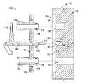
- FIG. 3Ais a cross-sectional side view of an exemplary fluid inlet adapter and a device according to certain aspects of the present disclosure.
- FIG. 3Bis a cross-sectional side view of the exemplary fluid inlet adapter of FIG. 3A mated with the docking location of the housing according to certain aspects of the present disclosure.
- FIGS. 4A-4Bdepict the position of the handle in exemplary unlatched and latched positions according to certain aspects of the present disclosure.
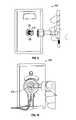
- FIGS. 5 and 6depict an exemplary inlet adapter configured to accept fluid from two different sources according to certain aspects of the present disclosure.
- FIGS. 7-10depict example connector configurations according to certain aspects of the present disclosure.
- FIGS. 1-2are front and back perspective views of an exemplary fluid inlet adapter 100 according to certain aspects of the present disclosure.
- the fluid inlet adapter 100also referred to herein as “the adapter 100 ,” comprises a body 110 with two inlets 120 , 130 that are configured to respectively mate with connectors 20 , 30 that are connected to two different fluid sources.
- the two connectors 20 and 30may comprise different configurations comprising attributes such as shape, the presence or absence of thread, keys, etc.
- Example connector configurationsare shown in FIGS. 7-10 .
- a handle 140is movably coupled to the body 110 and comprising an access control element 142 .
- the access control element 142is a paddle extending from a shaft 141 that is, in this example, perpendicular to the body 110 .
- the handle 140is shown in FIG. 1 in a latched position, wherein the access control element 142 is positioned in front of inlet 130 , thereby preventing a user from connecting a connector 30 to the inlet 130 .
- the access control element 142is disposed in front of the inlet 130 .
- the access control element 142is disposed proximate to the inlet 130 , e.g.
- the inlet 120is fully accessible in this position of the adapter 100 and a user may connect a connector 20 to the inlet 120 .
- the body 110may include one or more keying holes 111 that engage pins, posts, or other keying features (not shown in FIG. 1A ) of the connectors 20 , 30 .
- FIG. 2depicts the back of the adapter 100 .
- a center plane 101is defined relative to the body 110 and bisects the body 110 .
- the adapter 100has a first position, as shown in FIG. 2 , and a second position that is rotated 180° from the first position with respect to the plane of symmetry. Positions of the adapter 100 are discussed in greater detail with respect to FIGS. 5 and 6 .
- the adapter 100also comprises first and second coupling ports 116 that are symmetrically located on opposite sides of the center plane 101 on a back side of the body 110 .
- the first and second coupling ports 116are in respective fluid communication with the first and second inlets 120 , 130 .
- the coupling ports 116may be respectively aligned with the first and second inlets 120 , 130 .
- the coupling ports 116may be respectively offset from the first and second inlets 120 , 130 .
- the handle 140comprises a latching pin 144 that is disposed within a securing feature, for example slot 114 formed in the alignment feature 112 .
- the latching pin 144in this example, extends outward from the portion of the shaft 141 that extends beyond the bottom of the body 110 .
- the function of the pin latching 144 and the method by which the handle 140 secures the adapter 100 to a device, for example a ventilator (not shown),is discussed in greater detail with respect to FIGS. 4A-4B .
- FIG. 3Ais a cross-sectional side view of the exemplary fluid inlet adapter 100 and a device 10 according to certain aspects of the present disclosure.
- the device 10has a housing 52 with, in this example, a docking station 50 having an alignment slot 66 that is configured to accept the alignment feature 112 .
- a recess 62adjacent to the alignment slot 66 that is configured to accept an end of the handle 140 .
- a latching slot 64extends laterally from the recess 62 and is configured to engage the pin 144 when the handle 140 is rotated such that the pin extends from the alignment feature 112 , as is discussed in greater detail with respect to FIGS. 4A-4B .
- the housing 52comprises a fluid passage 80 is configured to accept a flow of a fluid.
- the device 10is a ventilator and the fluid passage 80 connects to a blower (not shown) that pumps the fluid from fluid passage 80 to a patient as is generally known to those of skill in the art and not repeated herein.
- the fluid passage 80is positioned relative to the alignment slot 66 such that one of the coupling ports 116 will be at least partially disposed within the fluid passage 80 when the adapter 100 is secured to the device 10 in either a first or second position.
- FIG. 3Adepicts the example adapter 100 secured to the docking station 50 in the first position, wherein the coupling port 116 that is in fluid communication with inlet 120 is also at least partially disposed within and in fluid communication with the fluid passage 80 .
- the adapter 100In the second position (not shown in FIG. 3A ), the adapter 100 is upside down from the position shown in FIG. 3A such that the coupling port 116 that is in fluid communication with inlet 130 is also at least partially disposed within and in fluid communication with the fluid passage 80 .
- the coupling ports 116may have a sealing feature 118 , for example an o-ring, that are configured to detachably and sealingly mate with the fluid passage 80 .
- the housingalso comprises a blind recess 54 that accepts the un-used coupling port 116 .
- the docking location 50may have a recess 56 configured to accept the body 110 such that the front of the body 110 is flush with the surface of the housing 52 .
- the docking location 50may also have a recess 70 position under a keying hole 111 .
- the recess 70may provide clearance for a keying feature of a mating connector or may provide a retention function.
- FIG. 3Bis a cross-sectional side view of the exemplary adapter 100 of FIG. 3A mated with the docking location 50 of the housing 52 according to certain aspects of the present disclosure. It can be seen that the lower coupling port 116 is partially disposed within the fluid passage 80 and the upper coupling port 116 is partially disposed within the blind recess 54 .
- FIGS. 4A-4Bdepict the position of the handle 140 in exemplary unlatched and latched positions according to certain aspects of the present disclosure.
- FIG. 4Adepicts the position of the handle 140 while in a “unlatched” position suitable for insertion of the alignment feature 112 into the alignment slot 66 of the docking station 50 .
- the pin 144is positioned completely within the slot 114 so as not to interfere with the alignment slot 66 .
- FIG. 4Bdepicts a “latched” position with handle 140 rotated so as to engage pin 144 in latching slot 64 .
- the access control element 142is disposed in front of the inlet 130 thereby obstructing access to the inlet 130 so as to discourage connection of a connector 30 to the inlet 130 while the adapter 100 is secured to the device 10 in this position.
- FIGS. 5 and 6depict an exemplary inlet adapter 100 configured to accept fluid from two different sources 20 , 30 according to certain aspects of the present disclosure.
- FIG. 5depicts the adapter 100 configured to enable inlet 120 to allow a connector 20 (not shown in FIG. 5 ) while blocking connection to the inlet 130 .
- the machine-detectable indicator 150is positioned in a first position, e.g. on the near side of alignment feature 112 .
- FIG. 6depicts the adapter 100 reversed in orientation and configured to allow inlet 130 to accept a connector 30 (not shown in FIG. 6 ) while blocking connection to the inlet 120 . It can be seen that when the adapter 100 is disposed in this position, which is the reverse of the position of FIG. 5 , that the machine-detectable indicator 150 is positioned in a second position, e.g. on the far side of alignment feature 112 , that is also the reverse of FIG. 5 .
- the device 50may have a first sensor (not shown in FIG. 5 ) positioned so as to detect the presence of the sensor in the position of FIG. 5 and a second sensor positioned so as to detect the presence of the sensor in the position of FIG. 6 .
- the use of two sensorsmay provide a positive indication of the position of the adapter 100 and, therefore, a positive indication of which gas is being provided.
- FIGS. 7-10depict example connector configurations according to certain aspects of the present disclosure.
- the adapter 100may comprise inlets that are configured to accept one of these type of connectors.
- FIG. 7depicts an “Ohmeda style” gas connection 200 wherein the gas-specific configuration of the connector is accomplished by one or more notches 220 on the outlet face 210 and a pin 230 on the adaptor.
- the notches 220 and pins 230may vary in position and/or size based on the gas required.
- FIG. 8depicts a “Chemetron style” gas connection 300 wherein the gas-specific configuration of the connector is accomplished by the position and shape of the latching hole 320 on the outlet face and alignment tabs 330 that mate with recesses 340 .
- the latching hole 320will vary in position and shape based on the gas required.
- FIG. 9depicts a “Diameter Index Safety System (DISS) style” gas connection 400 wherein the gas-specific configuration of the connector is accomplished by gas-specific threads disposed on a barrel 410 .
- the thread diameter and adaptor nipple sizemay vary based on the gas required.
- FIG. 10depicts a “Schrader style” gas connection 500 wherein the gas-specific configuration of the connector is accomplished by geometric indexing, i.e. each gas has a unique shape and size of the barrel 510
- the disclosed embodiments of the inlet adapterprovide a reliable means of configuring a device, such as a ventilator, to accept only one of a possible variety of gases. While the disclosed embodiment of the adapter has two inlets and accepts gas through one inlet while blocking the other inlet, other embodiments of the adapter may have three or more inlets and may be configured to accept gas through more than one of the three or more inlets.
- the machine-detectable indicator that is disclosed as a magnet hereinmay be any machine-readable element, for example a barcode or 2D matrix positioned to be read by a camera or scanner when the adapter is configured in a certain position.
- topshould be understood as referring to an arbitrary frame of reference, rather than to the ordinary gravitational frame of reference.
- a top surface, a bottom surface, a front surface, and a rear surfacemay extend upwardly, downwardly, diagonally, or horizontally in a gravitational frame of reference.
- a phrase such as an “aspect”does not imply that such aspect is essential to the subject technology or that such aspect applies to all configurations of the subject technology.
- a disclosure relating to an aspectmay apply to all configurations, or one or more configurations.
- a phrase such as an aspectmay refer to one or more aspects and vice versa.
- a phrase such as an “embodiment”does not imply that such embodiment is essential to the subject technology or that such embodiment applies to all configurations of the subject technology.
- a disclosure relating to an embodimentmay apply to all embodiments, or one or more embodiments.
- a phrase such an embodimentmay refer to one or more embodiments and vice versa.
Landscapes
- Health & Medical Sciences (AREA)
- Engineering & Computer Science (AREA)
- Heart & Thoracic Surgery (AREA)
- Public Health (AREA)
- Anesthesiology (AREA)
- Biomedical Technology (AREA)
- Hematology (AREA)
- Life Sciences & Earth Sciences (AREA)
- Animal Behavior & Ethology (AREA)
- General Health & Medical Sciences (AREA)
- Pulmonology (AREA)
- Veterinary Medicine (AREA)
- Emergency Medicine (AREA)
- General Engineering & Computer Science (AREA)
- Mechanical Engineering (AREA)
- Measuring Volume Flow (AREA)
- Structures Of Non-Positive Displacement Pumps (AREA)
- Quick-Acting Or Multi-Walled Pipe Joints (AREA)
- Sampling And Sample Adjustment (AREA)
- Details Of Connecting Devices For Male And Female Coupling (AREA)
Abstract
Description
Claims (19)
Priority Applications (27)
| Application Number | Priority Date | Filing Date | Title |
|---|---|---|---|
| US13/931,496US9795757B2 (en) | 2013-06-28 | 2013-06-28 | Fluid inlet adapter |
| CN201480037090.XACN105358202B (en) | 2013-06-28 | 2014-06-27 | ventilator system |
| CN201710584523.9ACN107362424A (en) | 2013-06-28 | 2014-06-27 | Ventilator system |
| JP2016524270AJP2016523176A (en) | 2013-06-28 | 2014-06-27 | Fluid inlet adapter |
| EP17162581.7AEP3219350B1 (en) | 2013-06-28 | 2014-06-27 | Ventilator system |
| US14/318,285US20150000669A1 (en) | 2013-06-28 | 2014-06-27 | Fluid inlet adapter |
| CA2914691ACA2914691A1 (en) | 2013-06-28 | 2014-06-27 | Fluid inlet adapter |
| ES14744689.2TES2632484T3 (en) | 2013-06-28 | 2014-06-27 | Fan system |
| EP20162775.9AEP3689404A1 (en) | 2013-06-28 | 2014-06-27 | Ventilator system |
| MX2015016910AMX2015016910A (en) | 2013-06-28 | 2014-06-27 | Fluid inlet adapter. |
| EP14742098.8AEP3013399A2 (en) | 2013-06-28 | 2014-06-27 | Fluid inlet adapter |
| BR112015032320ABR112015032320A2 (en) | 2013-06-28 | 2014-06-27 | ventilation system |
| RU2015155886ARU2015155886A (en) | 2013-06-28 | 2014-06-27 | LUNG ARTIFICIAL VENTILATION SYSTEM |
| MX2015017335AMX2015017335A (en) | 2013-06-28 | 2014-06-27 | Ventilator system. |
| EP14744689.2AEP3013400B8 (en) | 2013-06-28 | 2014-06-27 | Ventilator system |
| PCT/US2014/044737WO2014210561A2 (en) | 2013-06-28 | 2014-06-27 | Fluid inlet adapter |
| RU2015155887ARU2015155887A (en) | 2013-06-28 | 2014-06-27 | FLUID INLET TRANSITION DEVICE |
| AU2014302108AAU2014302108A1 (en) | 2013-06-28 | 2014-06-27 | Ventilator system |
| AU2014302103AAU2014302103A1 (en) | 2013-06-28 | 2014-06-27 | Fluid inlet adapter |
| JP2016524271AJP2016526639A (en) | 2013-06-28 | 2014-06-27 | Ventilator system |
| US14/318,504US20150007815A1 (en) | 2013-06-28 | 2014-06-27 | Ventilator system |
| CN201480036606.9ACN105358201B (en) | 2013-06-28 | 2014-06-27 | Fluid inlet adapter |
| PCT/US2014/044743WO2014210566A2 (en) | 2013-06-28 | 2014-06-27 | Ventilator system |
| CA2915686ACA2915686A1 (en) | 2013-06-28 | 2014-06-27 | Ventilator system |
| BR112015031447ABR112015031447A2 (en) | 2013-06-28 | 2014-06-27 | fluid inlet adapter |
| AU2015279625AAU2015279625A1 (en) | 2013-06-28 | 2015-06-26 | Fluid inlet adapter |
| CN201580034937.3ACN106659865A (en) | 2013-06-28 | 2015-06-26 | Fluid inlet adapter |
Applications Claiming Priority (1)
| Application Number | Priority Date | Filing Date | Title |
|---|---|---|---|
| US13/931,496US9795757B2 (en) | 2013-06-28 | 2013-06-28 | Fluid inlet adapter |
Related Child Applications (2)
| Application Number | Title | Priority Date | Filing Date |
|---|---|---|---|
| US13/931,418Continuation-In-PartUS9433743B2 (en) | 2013-06-28 | 2013-06-28 | Ventilator exhalation flow valve |
| US14/318,285Continuation-In-PartUS20150000669A1 (en) | 2013-06-28 | 2014-06-27 | Fluid inlet adapter |
Publications (2)
| Publication Number | Publication Date |
|---|---|
| US20150000653A1 US20150000653A1 (en) | 2015-01-01 |
| US9795757B2true US9795757B2 (en) | 2017-10-24 |
Family
ID=51213035
Family Applications (2)
| Application Number | Title | Priority Date | Filing Date |
|---|---|---|---|
| US13/931,496Expired - Fee RelatedUS9795757B2 (en) | 2013-06-28 | 2013-06-28 | Fluid inlet adapter |
| US14/318,285AbandonedUS20150000669A1 (en) | 2013-06-28 | 2014-06-27 | Fluid inlet adapter |
Family Applications After (1)
| Application Number | Title | Priority Date | Filing Date |
|---|---|---|---|
| US14/318,285AbandonedUS20150000669A1 (en) | 2013-06-28 | 2014-06-27 | Fluid inlet adapter |
Country Status (10)
| Country | Link |
|---|---|
| US (2) | US9795757B2 (en) |
| EP (1) | EP3013399A2 (en) |
| JP (1) | JP2016523176A (en) |
| CN (2) | CN105358201B (en) |
| AU (2) | AU2014302103A1 (en) |
| BR (1) | BR112015031447A2 (en) |
| CA (1) | CA2914691A1 (en) |
| MX (1) | MX2015016910A (en) |
| RU (1) | RU2015155887A (en) |
| WO (1) | WO2014210561A2 (en) |
Cited By (2)
| Publication number | Priority date | Publication date | Assignee | Title |
|---|---|---|---|---|
| US11334096B2 (en)* | 2018-07-17 | 2022-05-17 | Beijing Sevenstar Flow Co., Ltd. | Fluid sensor and mass flow controller |
| DE102022131453A1 (en) | 2022-11-29 | 2024-05-29 | Drägerwerk AG & Co. KGaA | Probe for a gas supply system |
Families Citing this family (11)
| Publication number | Priority date | Publication date | Assignee | Title |
|---|---|---|---|---|
| EP4169560B1 (en) | 2011-07-13 | 2025-09-17 | Fisher & Paykel Healthcare Limited | Bearing mount for a compressor or blower for providing respiratory assistance |
| CN205515844U (en) | 2012-12-18 | 2016-08-31 | 费雪派克医疗保健有限公司 | Breathe auxiliary device and be used for assembly of motor |
| NZ737589A (en) | 2015-06-24 | 2023-03-31 | Fisher & Paykel Healthcare Ltd | Breathing assistance apparatus |
| FR3040754B1 (en)* | 2015-09-04 | 2017-08-25 | Biomerieux Sa | DEVICE FOR CONNECTING AT LEAST ONE DRAIN PIPE OF A PRODUCT WITH MEANS FOR RECEIVING SAID PRODUCT, FOR EXAMPLE FROM A NUCLEIC ACID EXTRACTION APPARATUS |
| CN114288512B (en) | 2017-04-23 | 2024-12-13 | 费雪派克医疗保健有限公司 | Respiratory assistance equipment |
| US11048994B2 (en) | 2017-08-11 | 2021-06-29 | Norma U.S. Holding Llc | Fluid line connector and assembly with securement detection |
| WO2019033109A1 (en) | 2017-08-11 | 2019-02-14 | Norma U.S. Holding Llc | Fluid line connector and assembly with securement detection |
| US11306857B2 (en) | 2017-08-11 | 2022-04-19 | Norma U.S. Holding Llc | Fluid line connector and assembly with securement detection |
| US11199282B2 (en) | 2017-08-11 | 2021-12-14 | Norma U.S. Holding Llc | Fluid line connector and assembly with securement detection |
| AU2019390392B2 (en)* | 2018-11-26 | 2024-11-28 | Kpr U.S., Llc | Cassette for a flow control apparatus |
| DE202020103903U1 (en) | 2020-07-06 | 2020-07-13 | TI Automotive (Fuldabrück) GmbH | Connector for connecting two fluid-carrying elements |
Citations (127)
| Publication number | Priority date | Publication date | Assignee | Title |
|---|---|---|---|---|
| US2037880A (en) | 1933-11-17 | 1936-04-21 | Hartzell Industries | Fan |
| US2510125A (en) | 1946-07-30 | 1950-06-06 | Lawrence W Meakin | Connector for fluid or electrical lines or both |
| US2634311A (en) | 1950-01-31 | 1953-04-07 | Ralph E Darling | Composite fluid and electrical connector |
| US3140042A (en) | 1961-08-15 | 1964-07-07 | Fujii Noriyoshi | Wheels for centrifugal fans of the forward curved multiblade type |
| US3673541A (en) | 1970-08-06 | 1972-06-27 | Amp Inc | Composite electrical and fluid or air connector |
| US3776215A (en)* | 1971-11-01 | 1973-12-04 | Hugh J Mc | Humidifier means |
| US3788765A (en) | 1971-11-18 | 1974-01-29 | Laval Turbine | Low specific speed compressor |
| US4167369A (en) | 1977-04-04 | 1979-09-11 | Kabushiki Kaisha Komatsu Seisakusho | Impeller blading of a centrifugal compressor |
| US4243357A (en) | 1979-08-06 | 1981-01-06 | Cummins Engine Company, Inc. | Turbomachine |
| JPS56597A (en) | 1979-06-14 | 1981-01-07 | Matsushita Electric Ind Co Ltd | Motor blower |
| US4381668A (en) | 1979-08-22 | 1983-05-03 | Hitachi, Ltd. | Gas flow measuring apparatus |
| US4543041A (en) | 1981-08-07 | 1985-09-24 | Holset Engineering Company Limited | Impellor for centrifugal compressor |
| US4562744A (en) | 1984-05-04 | 1986-01-07 | Precision Measurement, Inc. | Method and apparatus for measuring the flowrate of compressible fluids |
| US4571801A (en) | 1983-06-15 | 1986-02-25 | Mks Instruments, Inc. | Method of manufacturing a cartridge unit for establishing controlled laminar-flow conditions |
| US4649760A (en) | 1985-04-18 | 1987-03-17 | Wedding James B | Method and apparatus for controlling flow volume through an aerosol sampler |
| US4754651A (en) | 1986-04-18 | 1988-07-05 | Shortridge Instruments, Inc. | Differential pressure apparatus for measuring flow and velocity |
| US4763645A (en) | 1987-08-25 | 1988-08-16 | Kapp Michael J | Tracheal tube filter |
| US4809742A (en) | 1988-04-18 | 1989-03-07 | Pneumo Abex Corporation | Control valve assembly including valve position sensor |
| US4825904A (en) | 1988-04-18 | 1989-05-02 | Pneumo Abex Corporation | Two position flow control valve assembly with position sensing |
| US4909545A (en) | 1982-12-15 | 1990-03-20 | Larry Hohol | Coupling |
| CN1041204A (en) | 1988-06-17 | 1990-04-11 | 松下电器产业株式会社 | Impeller of multi-blade blower |
| US4978281A (en) | 1988-08-19 | 1990-12-18 | Conger William W Iv | Vibration dampened blower |
| US5127400A (en) | 1990-03-23 | 1992-07-07 | Bird Products Corp. | Ventilator exhalation valve |
| US5190068A (en) | 1992-07-02 | 1993-03-02 | Brian Philbin | Control apparatus and method for controlling fluid flows and pressures |
| US5265594A (en) | 1990-10-30 | 1993-11-30 | Siemens Aktiengesellschaft | Apparatus for regulating the flow-through amount of a flowing medium |
| US5277196A (en) | 1992-03-31 | 1994-01-11 | The United States Of America As Represented By The Department Of Health And Human Services | Portable spirometer with improved accuracy |
| US5295397A (en) | 1991-07-15 | 1994-03-22 | The Texas A & M University System | Slotted orifice flowmeter |
| US5331995A (en) | 1992-07-17 | 1994-07-26 | Bear Medical Systems, Inc. | Flow control system for medical ventilator |
| US5339807A (en) | 1992-09-22 | 1994-08-23 | Puritan-Bennett Corporation | Exhalation valve stabilizing apparatus |
| US5365795A (en) | 1993-05-20 | 1994-11-22 | Brower Jr William B | Improved method for determining flow rates in venturis, orifices and flow nozzles involving total pressure and static pressure measurements |
| US5461932A (en) | 1991-07-15 | 1995-10-31 | Texas A & M University System | Slotted orifice flowmeter |
| US5478206A (en) | 1991-03-23 | 1995-12-26 | Robert Bosch Gmbh | Impeller for a radial fan |
| US5537992A (en) | 1994-05-06 | 1996-07-23 | Siemens Elema Ab | Anesthetic system having electronic safety interlock system |
| US5572992A (en) | 1994-03-04 | 1996-11-12 | Instrumentarium Corp. | Method and apparatus for identifying an anesthetic fluid container and/or for detecting a connection between the container and a conduit supplying a gas to a patient |
| US5604681A (en) | 1994-06-03 | 1997-02-18 | Dover Corporation | Coupler identification systems |
| US5606236A (en) | 1995-01-17 | 1997-02-25 | Eaton Corporation | Two wire position sense and control of modulating gas valve or other electromechanical actuators |
| EP0829793A1 (en) | 1996-09-06 | 1998-03-18 | Berkin B.V. | Method for momentarily identifying a gas or liquid flow, and device for carrying out the method |
| US5771884A (en) | 1997-03-14 | 1998-06-30 | Nellcor Puritan Bennett Incorporated | Magnetic exhalation valve with compensation for temperature and patient airway pressure induced changes to the magnetic field |
| US5918596A (en) | 1997-04-22 | 1999-07-06 | Instrumentarium Corp. | Special gas dose delivery apparatus for respiration equipment |
| US5954051A (en) | 1997-02-06 | 1999-09-21 | Instrumentarium Oy | Ventilator for intensified breathing and valve in patient conduit of apparatus for intensified breathing |
| US6017315A (en) | 1998-02-25 | 2000-01-25 | Respironics, Inc. | Patient monitor and method of using same |
| US6139262A (en) | 1998-05-08 | 2000-10-31 | York International Corporation | Variable geometry diffuser |
| US6151557A (en) | 1998-01-13 | 2000-11-21 | Rosemount Inc. | Friction flowmeter with improved software |
| WO2001038832A2 (en) | 1999-11-24 | 2001-05-31 | S.C. Ack S.R.L. | System for metering fluids |
| EP1127583A2 (en) | 2000-02-24 | 2001-08-29 | Siemens-Elema AB | Conduit with transmission line |
| US20020085952A1 (en) | 2000-09-27 | 2002-07-04 | Ellingboe Bruce S. | Blood perfusion system |
| US6422092B1 (en) | 1998-09-10 | 2002-07-23 | The Texas A&M University System | Multiple-phase flow meter |
| US6422256B1 (en) | 1998-10-08 | 2002-07-23 | Mott Metallurgical Corporation | Fluid flow controlling |
| US20020198668A1 (en) | 2001-04-24 | 2002-12-26 | Lull John M. | System and method for a mass flow controller |
| US6553923B2 (en) | 2000-08-30 | 2003-04-29 | William Stuart Gatley, Jr. | Blower housing with maximized interior spacing |
| US20030106554A1 (en) | 2001-11-30 | 2003-06-12 | De Silva Adrian D. | Gas identification system and volumetric ally correct gas delivery system |
| US6578818B1 (en) | 1998-03-10 | 2003-06-17 | Robert Bosch Gmbh | Valve device |
| US6609431B1 (en) | 2000-09-29 | 2003-08-26 | Xellogy, Inc. | Flow measuring device based on predetermine class of liquid |
| US6622724B1 (en) | 2000-06-19 | 2003-09-23 | Respironics, Inc. | Impeller and a pressure support system and method using such an impeller |
| US20030220605A1 (en) | 2002-05-24 | 2003-11-27 | Bowman Joseph H. | Disposable medical fluid unit having rigid frame |
| US20040074311A1 (en) | 2002-07-19 | 2004-04-22 | Celerity Group, Inc. | Methods and apparatus for pressure compensation in a mass flow controller |
| US20040177703A1 (en) | 2003-03-12 | 2004-09-16 | Schumacher Mark S. | Flow instrument with multisensors |
| US20040187871A1 (en) | 2003-03-28 | 2004-09-30 | Ric Investments, Inc. | Pressure support compliance monitoring system |
| US6820620B2 (en) | 2000-12-22 | 2004-11-23 | Jean-Denis Rochat | Respiratory assistance apparatus |
| US20050004534A1 (en)* | 2001-12-26 | 2005-01-06 | Lockwood Jeffery S | Vented vacuum bandage and method |
| US6945123B1 (en) | 2004-06-28 | 2005-09-20 | The General Electric Company | Gas flow sensor having redundant flow sensing capability |
| US20050241412A1 (en) | 2002-05-24 | 2005-11-03 | Tison Stuart A | Slotted flow restrictor for a mass flow meter |
| WO2006024532A1 (en) | 2004-09-03 | 2006-03-09 | Ric Investments, Llc | Gas flow control in a ventilator |
| US20060076419A1 (en) | 2004-09-24 | 2006-04-13 | Colder Products Company | Coupler with radio frequency identification tag |
| US20060079765A1 (en) | 2004-10-13 | 2006-04-13 | Liebel-Flarsheim Company | Powerhead of a power injection system |
| EP1658874A2 (en) | 2004-11-22 | 2006-05-24 | Universitätsklinikum Erlangen | Gas valve, system of gas checking as well as method of checking a gas collectable through the valve |
| US20060144163A1 (en) | 2002-11-20 | 2006-07-06 | Harri Friberg | Gas flow measuring device |
| US20060162466A1 (en) | 2002-07-19 | 2006-07-27 | Christopher Wargo | Fluid flow measuring and proportional fluid flow control device |
| US7107834B2 (en) | 2004-11-12 | 2006-09-19 | Mks Instruments, Inc. | Thermal mass flow rate sensor including bypass passageways and a sensor passageway having similar entrance effects |
| US7121139B2 (en) | 2004-11-12 | 2006-10-17 | Mks Instruments, Inc. | Thermal mass flow rate sensor having fixed bypass ratio |
| US20060236781A1 (en) | 2003-07-03 | 2006-10-26 | Fujikin Incorporated | Differential pressure type flowmeter and differential pressure type flowmeter controller |
| US20070193369A1 (en) | 2006-02-15 | 2007-08-23 | Evans Russell N | Multiphasic overreading correction in a process variable transmitter |
| US20070265877A1 (en) | 2006-05-12 | 2007-11-15 | Rice Caeli B D | Informative accessories |
| US20070277824A1 (en)* | 2006-05-31 | 2007-12-06 | Acoba, L.L.C. | Hose Connection System For Narially Sensitive Diagnostic Devices |
| US20080059084A1 (en) | 2006-09-05 | 2008-03-06 | Celerity, Inc. | Multi-gas flow device |
| CN101225881A (en) | 2007-12-19 | 2008-07-23 | 哈尔滨工业大学 | High-speed electro-hydraulic switching valve directly driven by giant magnetostrictive actuator |
| US20080283062A1 (en) | 2007-05-18 | 2008-11-20 | Esposito Jr Anthony J | Respiratory Component Measurement System |
| US20090038615A1 (en) | 2006-02-23 | 2009-02-12 | Meditren Limited | Breathing apparatus |
| US20090093774A1 (en) | 2007-10-04 | 2009-04-09 | Baxter International Inc. | Ambulatory pump with intelligent flow control |
| US20090095068A1 (en) | 2007-10-10 | 2009-04-16 | Celerity, Inc. | System for and method of providing a wide-range flow controller |
| US20090113996A1 (en) | 2007-10-04 | 2009-05-07 | Baxter International Inc. | System and method for measuring liquid viscosity in a fluid delivery system |
| US20090293634A1 (en) | 2008-05-27 | 2009-12-03 | Joo Tim Ong | Method of measuring multiphase flow |
| US20090326839A1 (en) | 2008-06-27 | 2009-12-31 | Steven Bruce Rogers | Velocity-enhanced flow measurement |
| US20100031737A1 (en) | 2008-08-11 | 2010-02-11 | Hitachi Automotive Systems, Ltd. | Mass air flow measurement device |
| CN101687086A (en) | 2007-06-28 | 2010-03-31 | 马奎特紧急护理公司 | A patient ventilation system with gas identification means |
| US20100139660A1 (en) | 2008-12-10 | 2010-06-10 | Carmeli Adahan | Pump and exhalation valve control for respirator apparatus |
| US20100229967A1 (en) | 2009-03-11 | 2010-09-16 | Horiba Stec, Co., Ltd. | Mass flow controller verifying system, verifying method and verifying program |
| US20100236552A1 (en) | 2005-08-15 | 2010-09-23 | Resmed Limited | Cpap Systems |
| US7819022B2 (en) | 2006-03-16 | 2010-10-26 | Sensorteknikk As | Method and device for recording characteristic state, amount and composition of a flowing medium |
| US7826986B2 (en) | 2008-09-26 | 2010-11-02 | Advanced Energy Industries, Inc. | Method and system for operating a mass flow controller |
| US20100307490A1 (en) | 2007-11-14 | 2010-12-09 | Stefan Broborg | Patient cassette with variable patient circuit volume |
| US20110100364A1 (en) | 2009-11-02 | 2011-05-05 | Joseph Dee Faram | Multiple conduit connector apparatus and method |
| WO2011055254A1 (en) | 2009-11-09 | 2011-05-12 | Koninklijke Philips Electronics N.V. | Flow sensing device with temperature compensation |
| US20110126834A1 (en) | 2009-12-01 | 2011-06-02 | Nellcor Puritan Bennett Llc | Exhalation Valve Assembly With Integral Flow Sensor |
| US20110126837A1 (en) | 2009-12-01 | 2011-06-02 | Nellcor Puritan Bennett Llc | Exhalation Valve Assembly With Integrated Filter |
| CN102155570A (en) | 2011-04-22 | 2011-08-17 | 浙江大学 | Pneumatic high-speed switch valve driven by giant magnetostriction |
| US20110301867A1 (en) | 2010-06-08 | 2011-12-08 | Rosemount Inc. | Fluid flow measurement with phase-based diagnostics |
| EP2402616A1 (en) | 2009-07-13 | 2012-01-04 | Mitsubishi Heavy Industries, Ltd. | Impeller and rotary machine |
| US20120065533A1 (en) | 2010-05-28 | 2012-03-15 | Carrillo Jr Oscar | Positive Airway Pressure System and Method |
| US20120085349A1 (en) | 2010-10-06 | 2012-04-12 | Honeywell International Inc. | Respirator with end-of-service-life detection |
| US20120185102A1 (en) | 2011-01-18 | 2012-07-19 | Flow Control Industries, Inc. | Pressure compensated flow rate controller with btu meter |
| CN202366282U (en) | 2011-12-04 | 2012-08-08 | 任梅 | Breathing device for emergency treatment |
| US20120204874A1 (en) | 2009-10-28 | 2012-08-16 | Koninklijke Philips Electronics N.V. | Pressure support sustem with inductive tubing |
| US20120229272A1 (en) | 2009-11-11 | 2012-09-13 | Koninklijke Philips Electronics N.V. | Wireless identification of a component of a pressure support system |
| CN102686888A (en) | 2009-10-29 | 2012-09-19 | 雷斯麦德有限公司 | Patient ventilating device and components thereof |
| US20120284991A1 (en) | 2009-12-07 | 2012-11-15 | Matthew Kusz | Configurable port fitment, kit, and related methods |
| US20120285455A1 (en) | 2011-05-11 | 2012-11-15 | Varga Christopher M | Smart connections |
| US20120318383A1 (en) | 2011-06-17 | 2012-12-20 | Horiba Stec, Co., Ltd. | Flow rate measuring device and flow rate controller |
| WO2013002699A1 (en) | 2011-06-30 | 2013-01-03 | Cejn Ab | Quick coupling for pipes/hoses with locking feature |
| CN102927292A (en) | 2012-11-01 | 2013-02-13 | 浙江理工大学 | Solenoid valve and weft yarn tension device |
| US20130036806A1 (en) | 2011-08-09 | 2013-02-14 | Denso Corporation | Air flow measuring device |
| US20130079667A1 (en) | 2011-09-28 | 2013-03-28 | General Electric Company | Flow sensor with mems sensing device and method for using same |
| CN202870631U (en) | 2012-10-16 | 2013-04-10 | 深圳市安保科技有限公司 | Respiratory flow adjusting device and respirator |
| CN103041492A (en) | 2012-12-29 | 2013-04-17 | 平湖市瑞阳精密机械有限公司 | Medical gas valve |
| US20130153040A1 (en) | 2006-08-03 | 2013-06-20 | Hitachi Metals, Ltd. | Flow rate control using mass flow rate control device |
| US8504318B2 (en) | 2008-03-05 | 2013-08-06 | Brooks Instruments, Llc | System, method and computer program for determining fluid flow rate using a pressure sensor and a thermal mass flow sensor |
| US20130220314A1 (en) | 2012-02-29 | 2013-08-29 | General Electric Company | Medical vaporizer with porous vaporization element |
| US20130247905A1 (en) | 2010-12-03 | 2013-09-26 | Intersurgical Ag | Breathing systems |
| US20140054479A1 (en) | 2011-12-30 | 2014-02-27 | Beijing Aeonmed Co., Ltd. | Flow control proportional valve |
| US20140066880A1 (en) | 2011-06-22 | 2014-03-06 | Crisi Medical Systems, Inc. | Selectively Controlling Fluid Flow Through A Fluid Pathway |
| US20140182590A1 (en) | 2012-12-28 | 2014-07-03 | Newport Medical Instruments, Incorporated | Ventilator pressure oscillation filter |
| US20140251322A1 (en) | 2011-11-01 | 2014-09-11 | Intersurgical Ag | Breathing systems |
| US20150020807A1 (en) | 2012-02-29 | 2015-01-22 | Koninklijke Philips N.V. | Compensating for variations in air density in a pressure support device |
| US20150096560A1 (en) | 2012-04-27 | 2015-04-09 | Fisher & Paykel Place, East Limited | Usability features for respiratory humidification system |
| US9003877B2 (en) | 2010-06-15 | 2015-04-14 | Honeywell International Inc. | Flow sensor assembly |
| US20150143921A1 (en) | 2012-06-04 | 2015-05-28 | Hans-Jürgen Postberg | Device for measuring differential pressure |
| US20160256646A1 (en) | 2013-10-07 | 2016-09-08 | Endoclear Llc | Systems and methods for selectively blocking respiratory air flow |
Family Cites Families (4)
| Publication number | Priority date | Publication date | Assignee | Title |
|---|---|---|---|---|
| DE866582C (en)* | 1944-06-27 | 1953-02-12 | Messerschmitt Boelkow Blohm | Securing for hose screw connections |
| US4211439A (en)* | 1978-07-26 | 1980-07-08 | Moldestad Jon P | Safety device for hose connections |
| US8109268B2 (en)* | 2007-01-08 | 2012-02-07 | Dräger Medical GmbH | Device for detecting a gas volume flow |
| US8997736B2 (en)* | 2008-12-16 | 2015-04-07 | Koninklijke Philips N.V. | Interface apparatus identification system and method and differentiating feature therefor |
- 2013
- 2013-06-28USUS13/931,496patent/US9795757B2/ennot_activeExpired - Fee Related
- 2014
- 2014-06-27EPEP14742098.8Apatent/EP3013399A2/ennot_activeWithdrawn
- 2014-06-27CACA2914691Apatent/CA2914691A1/ennot_activeAbandoned
- 2014-06-27RURU2015155887Apatent/RU2015155887A/ennot_activeApplication Discontinuation
- 2014-06-27WOPCT/US2014/044737patent/WO2014210561A2/enactiveApplication Filing
- 2014-06-27USUS14/318,285patent/US20150000669A1/ennot_activeAbandoned
- 2014-06-27MXMX2015016910Apatent/MX2015016910A/enunknown
- 2014-06-27CNCN201480036606.9Apatent/CN105358201B/ennot_activeExpired - Fee Related
- 2014-06-27JPJP2016524270Apatent/JP2016523176A/enactivePending
- 2014-06-27BRBR112015031447Apatent/BR112015031447A2/ennot_activeApplication Discontinuation
- 2014-06-27AUAU2014302103Apatent/AU2014302103A1/ennot_activeAbandoned
- 2015
- 2015-06-26CNCN201580034937.3Apatent/CN106659865A/enactivePending
- 2015-06-26AUAU2015279625Apatent/AU2015279625A1/ennot_activeAbandoned
Patent Citations (133)
| Publication number | Priority date | Publication date | Assignee | Title |
|---|---|---|---|---|
| US2037880A (en) | 1933-11-17 | 1936-04-21 | Hartzell Industries | Fan |
| US2510125A (en) | 1946-07-30 | 1950-06-06 | Lawrence W Meakin | Connector for fluid or electrical lines or both |
| US2634311A (en) | 1950-01-31 | 1953-04-07 | Ralph E Darling | Composite fluid and electrical connector |
| US3140042A (en) | 1961-08-15 | 1964-07-07 | Fujii Noriyoshi | Wheels for centrifugal fans of the forward curved multiblade type |
| US3673541A (en) | 1970-08-06 | 1972-06-27 | Amp Inc | Composite electrical and fluid or air connector |
| US3776215A (en)* | 1971-11-01 | 1973-12-04 | Hugh J Mc | Humidifier means |
| US3788765A (en) | 1971-11-18 | 1974-01-29 | Laval Turbine | Low specific speed compressor |
| US4167369A (en) | 1977-04-04 | 1979-09-11 | Kabushiki Kaisha Komatsu Seisakusho | Impeller blading of a centrifugal compressor |
| JPS56597A (en) | 1979-06-14 | 1981-01-07 | Matsushita Electric Ind Co Ltd | Motor blower |
| US4243357A (en) | 1979-08-06 | 1981-01-06 | Cummins Engine Company, Inc. | Turbomachine |
| US4381668A (en) | 1979-08-22 | 1983-05-03 | Hitachi, Ltd. | Gas flow measuring apparatus |
| US4543041A (en) | 1981-08-07 | 1985-09-24 | Holset Engineering Company Limited | Impellor for centrifugal compressor |
| US4909545A (en) | 1982-12-15 | 1990-03-20 | Larry Hohol | Coupling |
| US4571801A (en) | 1983-06-15 | 1986-02-25 | Mks Instruments, Inc. | Method of manufacturing a cartridge unit for establishing controlled laminar-flow conditions |
| US4562744A (en) | 1984-05-04 | 1986-01-07 | Precision Measurement, Inc. | Method and apparatus for measuring the flowrate of compressible fluids |
| US4649760A (en) | 1985-04-18 | 1987-03-17 | Wedding James B | Method and apparatus for controlling flow volume through an aerosol sampler |
| US4754651A (en) | 1986-04-18 | 1988-07-05 | Shortridge Instruments, Inc. | Differential pressure apparatus for measuring flow and velocity |
| US4763645A (en) | 1987-08-25 | 1988-08-16 | Kapp Michael J | Tracheal tube filter |
| US4809742A (en) | 1988-04-18 | 1989-03-07 | Pneumo Abex Corporation | Control valve assembly including valve position sensor |
| US4825904A (en) | 1988-04-18 | 1989-05-02 | Pneumo Abex Corporation | Two position flow control valve assembly with position sensing |
| CN1041204A (en) | 1988-06-17 | 1990-04-11 | 松下电器产业株式会社 | Impeller of multi-blade blower |
| US5064346A (en) | 1988-06-17 | 1991-11-12 | Matsushita Electric Industrial Co., Ltd. | Impeller of multiblade blower |
| US4978281A (en) | 1988-08-19 | 1990-12-18 | Conger William W Iv | Vibration dampened blower |
| US5127400A (en) | 1990-03-23 | 1992-07-07 | Bird Products Corp. | Ventilator exhalation valve |
| US5265594A (en) | 1990-10-30 | 1993-11-30 | Siemens Aktiengesellschaft | Apparatus for regulating the flow-through amount of a flowing medium |
| US5478206A (en) | 1991-03-23 | 1995-12-26 | Robert Bosch Gmbh | Impeller for a radial fan |
| US5461932A (en) | 1991-07-15 | 1995-10-31 | Texas A & M University System | Slotted orifice flowmeter |
| US5295397A (en) | 1991-07-15 | 1994-03-22 | The Texas A & M University System | Slotted orifice flowmeter |
| US5277196A (en) | 1992-03-31 | 1994-01-11 | The United States Of America As Represented By The Department Of Health And Human Services | Portable spirometer with improved accuracy |
| US5190068A (en) | 1992-07-02 | 1993-03-02 | Brian Philbin | Control apparatus and method for controlling fluid flows and pressures |
| US5331995A (en) | 1992-07-17 | 1994-07-26 | Bear Medical Systems, Inc. | Flow control system for medical ventilator |
| US5339807A (en) | 1992-09-22 | 1994-08-23 | Puritan-Bennett Corporation | Exhalation valve stabilizing apparatus |
| US5365795A (en) | 1993-05-20 | 1994-11-22 | Brower Jr William B | Improved method for determining flow rates in venturis, orifices and flow nozzles involving total pressure and static pressure measurements |
| US5572992A (en) | 1994-03-04 | 1996-11-12 | Instrumentarium Corp. | Method and apparatus for identifying an anesthetic fluid container and/or for detecting a connection between the container and a conduit supplying a gas to a patient |
| US5537992A (en) | 1994-05-06 | 1996-07-23 | Siemens Elema Ab | Anesthetic system having electronic safety interlock system |
| US5604681A (en) | 1994-06-03 | 1997-02-18 | Dover Corporation | Coupler identification systems |
| US5606236A (en) | 1995-01-17 | 1997-02-25 | Eaton Corporation | Two wire position sense and control of modulating gas valve or other electromechanical actuators |
| EP0829793A1 (en) | 1996-09-06 | 1998-03-18 | Berkin B.V. | Method for momentarily identifying a gas or liquid flow, and device for carrying out the method |
| US5954051A (en) | 1997-02-06 | 1999-09-21 | Instrumentarium Oy | Ventilator for intensified breathing and valve in patient conduit of apparatus for intensified breathing |
| US5771884A (en) | 1997-03-14 | 1998-06-30 | Nellcor Puritan Bennett Incorporated | Magnetic exhalation valve with compensation for temperature and patient airway pressure induced changes to the magnetic field |
| US5918596A (en) | 1997-04-22 | 1999-07-06 | Instrumentarium Corp. | Special gas dose delivery apparatus for respiration equipment |
| US6151557A (en) | 1998-01-13 | 2000-11-21 | Rosemount Inc. | Friction flowmeter with improved software |
| US6017315A (en) | 1998-02-25 | 2000-01-25 | Respironics, Inc. | Patient monitor and method of using same |
| US6578818B1 (en) | 1998-03-10 | 2003-06-17 | Robert Bosch Gmbh | Valve device |
| US6139262A (en) | 1998-05-08 | 2000-10-31 | York International Corporation | Variable geometry diffuser |
| US6422092B1 (en) | 1998-09-10 | 2002-07-23 | The Texas A&M University System | Multiple-phase flow meter |
| US6422256B1 (en) | 1998-10-08 | 2002-07-23 | Mott Metallurgical Corporation | Fluid flow controlling |
| WO2001038832A2 (en) | 1999-11-24 | 2001-05-31 | S.C. Ack S.R.L. | System for metering fluids |
| EP1127583A2 (en) | 2000-02-24 | 2001-08-29 | Siemens-Elema AB | Conduit with transmission line |
| US6622724B1 (en) | 2000-06-19 | 2003-09-23 | Respironics, Inc. | Impeller and a pressure support system and method using such an impeller |
| US6553923B2 (en) | 2000-08-30 | 2003-04-29 | William Stuart Gatley, Jr. | Blower housing with maximized interior spacing |
| US20020085952A1 (en) | 2000-09-27 | 2002-07-04 | Ellingboe Bruce S. | Blood perfusion system |
| US6609431B1 (en) | 2000-09-29 | 2003-08-26 | Xellogy, Inc. | Flow measuring device based on predetermine class of liquid |
| US6820620B2 (en) | 2000-12-22 | 2004-11-23 | Jean-Denis Rochat | Respiratory assistance apparatus |
| US20020198668A1 (en) | 2001-04-24 | 2002-12-26 | Lull John M. | System and method for a mass flow controller |
| US20080105259A1 (en) | 2001-11-30 | 2008-05-08 | Viasys Healthcare, Critical Care Division | Gas identification system and respiratory technologies volumetrically corrected gas delivery system |
| US20030106554A1 (en) | 2001-11-30 | 2003-06-12 | De Silva Adrian D. | Gas identification system and volumetric ally correct gas delivery system |
| US20050004534A1 (en)* | 2001-12-26 | 2005-01-06 | Lockwood Jeffery S | Vented vacuum bandage and method |
| US20050241412A1 (en) | 2002-05-24 | 2005-11-03 | Tison Stuart A | Slotted flow restrictor for a mass flow meter |
| US20030220605A1 (en) | 2002-05-24 | 2003-11-27 | Bowman Joseph H. | Disposable medical fluid unit having rigid frame |
| US20040074311A1 (en) | 2002-07-19 | 2004-04-22 | Celerity Group, Inc. | Methods and apparatus for pressure compensation in a mass flow controller |
| US20060162466A1 (en) | 2002-07-19 | 2006-07-27 | Christopher Wargo | Fluid flow measuring and proportional fluid flow control device |
| US20060144163A1 (en) | 2002-11-20 | 2006-07-06 | Harri Friberg | Gas flow measuring device |
| US20040177703A1 (en) | 2003-03-12 | 2004-09-16 | Schumacher Mark S. | Flow instrument with multisensors |
| US20040187871A1 (en) | 2003-03-28 | 2004-09-30 | Ric Investments, Inc. | Pressure support compliance monitoring system |
| US20060236781A1 (en) | 2003-07-03 | 2006-10-26 | Fujikin Incorporated | Differential pressure type flowmeter and differential pressure type flowmeter controller |
| US6945123B1 (en) | 2004-06-28 | 2005-09-20 | The General Electric Company | Gas flow sensor having redundant flow sensing capability |
| WO2006024532A1 (en) | 2004-09-03 | 2006-03-09 | Ric Investments, Llc | Gas flow control in a ventilator |
| US20080092891A1 (en) | 2004-09-03 | 2008-04-24 | Anagram Consultants Ag | Gas Flow Control In A Ventilator |
| US20060076419A1 (en) | 2004-09-24 | 2006-04-13 | Colder Products Company | Coupler with radio frequency identification tag |
| US20060079765A1 (en) | 2004-10-13 | 2006-04-13 | Liebel-Flarsheim Company | Powerhead of a power injection system |
| US7107834B2 (en) | 2004-11-12 | 2006-09-19 | Mks Instruments, Inc. | Thermal mass flow rate sensor including bypass passageways and a sensor passageway having similar entrance effects |
| US7121139B2 (en) | 2004-11-12 | 2006-10-17 | Mks Instruments, Inc. | Thermal mass flow rate sensor having fixed bypass ratio |
| EP1658874A2 (en) | 2004-11-22 | 2006-05-24 | Universitätsklinikum Erlangen | Gas valve, system of gas checking as well as method of checking a gas collectable through the valve |
| US20100236552A1 (en) | 2005-08-15 | 2010-09-23 | Resmed Limited | Cpap Systems |
| US20070193369A1 (en) | 2006-02-15 | 2007-08-23 | Evans Russell N | Multiphasic overreading correction in a process variable transmitter |
| US20090038615A1 (en) | 2006-02-23 | 2009-02-12 | Meditren Limited | Breathing apparatus |
| US7819022B2 (en) | 2006-03-16 | 2010-10-26 | Sensorteknikk As | Method and device for recording characteristic state, amount and composition of a flowing medium |
| US20070265877A1 (en) | 2006-05-12 | 2007-11-15 | Rice Caeli B D | Informative accessories |
| US20070277824A1 (en)* | 2006-05-31 | 2007-12-06 | Acoba, L.L.C. | Hose Connection System For Narially Sensitive Diagnostic Devices |
| US20130153040A1 (en) | 2006-08-03 | 2013-06-20 | Hitachi Metals, Ltd. | Flow rate control using mass flow rate control device |
| US20080059084A1 (en) | 2006-09-05 | 2008-03-06 | Celerity, Inc. | Multi-gas flow device |
| US7636640B2 (en) | 2006-09-05 | 2009-12-22 | Brooks Instrument, Llc | Multi-gas flow device |
| US20080283062A1 (en) | 2007-05-18 | 2008-11-20 | Esposito Jr Anthony J | Respiratory Component Measurement System |
| CN101687086A (en) | 2007-06-28 | 2010-03-31 | 马奎特紧急护理公司 | A patient ventilation system with gas identification means |
| US20090093774A1 (en) | 2007-10-04 | 2009-04-09 | Baxter International Inc. | Ambulatory pump with intelligent flow control |
| US20090113996A1 (en) | 2007-10-04 | 2009-05-07 | Baxter International Inc. | System and method for measuring liquid viscosity in a fluid delivery system |
| US20090095068A1 (en) | 2007-10-10 | 2009-04-16 | Celerity, Inc. | System for and method of providing a wide-range flow controller |
| US20100307490A1 (en) | 2007-11-14 | 2010-12-09 | Stefan Broborg | Patient cassette with variable patient circuit volume |
| CN101225881A (en) | 2007-12-19 | 2008-07-23 | 哈尔滨工业大学 | High-speed electro-hydraulic switching valve directly driven by giant magnetostrictive actuator |
| US8504318B2 (en) | 2008-03-05 | 2013-08-06 | Brooks Instruments, Llc | System, method and computer program for determining fluid flow rate using a pressure sensor and a thermal mass flow sensor |
| US20090293634A1 (en) | 2008-05-27 | 2009-12-03 | Joo Tim Ong | Method of measuring multiphase flow |
| US20090326839A1 (en) | 2008-06-27 | 2009-12-31 | Steven Bruce Rogers | Velocity-enhanced flow measurement |
| US20100031737A1 (en) | 2008-08-11 | 2010-02-11 | Hitachi Automotive Systems, Ltd. | Mass air flow measurement device |
| US7826986B2 (en) | 2008-09-26 | 2010-11-02 | Advanced Energy Industries, Inc. | Method and system for operating a mass flow controller |
| US20100139660A1 (en) | 2008-12-10 | 2010-06-10 | Carmeli Adahan | Pump and exhalation valve control for respirator apparatus |
| US20100229967A1 (en) | 2009-03-11 | 2010-09-16 | Horiba Stec, Co., Ltd. | Mass flow controller verifying system, verifying method and verifying program |
| EP2402616A1 (en) | 2009-07-13 | 2012-01-04 | Mitsubishi Heavy Industries, Ltd. | Impeller and rotary machine |
| US20120204874A1 (en) | 2009-10-28 | 2012-08-16 | Koninklijke Philips Electronics N.V. | Pressure support sustem with inductive tubing |
| US20120285454A1 (en) | 2009-10-29 | 2012-11-15 | Resmed Ltd. | Patient ventilation device and components thereof |
| CN102686888A (en) | 2009-10-29 | 2012-09-19 | 雷斯麦德有限公司 | Patient ventilating device and components thereof |
| US20110100364A1 (en) | 2009-11-02 | 2011-05-05 | Joseph Dee Faram | Multiple conduit connector apparatus and method |
| WO2011055254A1 (en) | 2009-11-09 | 2011-05-12 | Koninklijke Philips Electronics N.V. | Flow sensing device with temperature compensation |
| US20120226449A1 (en) | 2009-11-09 | 2012-09-06 | Koninklijke Philips Electronics N.V. | Flow sensing device with temperature compensation |
| US20120229272A1 (en) | 2009-11-11 | 2012-09-13 | Koninklijke Philips Electronics N.V. | Wireless identification of a component of a pressure support system |
| US20110126834A1 (en) | 2009-12-01 | 2011-06-02 | Nellcor Puritan Bennett Llc | Exhalation Valve Assembly With Integral Flow Sensor |
| US20110126837A1 (en) | 2009-12-01 | 2011-06-02 | Nellcor Puritan Bennett Llc | Exhalation Valve Assembly With Integrated Filter |
| US20120284991A1 (en) | 2009-12-07 | 2012-11-15 | Matthew Kusz | Configurable port fitment, kit, and related methods |
| US20120065533A1 (en) | 2010-05-28 | 2012-03-15 | Carrillo Jr Oscar | Positive Airway Pressure System and Method |
| US20110301867A1 (en) | 2010-06-08 | 2011-12-08 | Rosemount Inc. | Fluid flow measurement with phase-based diagnostics |
| US9003877B2 (en) | 2010-06-15 | 2015-04-14 | Honeywell International Inc. | Flow sensor assembly |
| US20120085349A1 (en) | 2010-10-06 | 2012-04-12 | Honeywell International Inc. | Respirator with end-of-service-life detection |
| US20130247905A1 (en) | 2010-12-03 | 2013-09-26 | Intersurgical Ag | Breathing systems |
| US20120185102A1 (en) | 2011-01-18 | 2012-07-19 | Flow Control Industries, Inc. | Pressure compensated flow rate controller with btu meter |
| CN102155570A (en) | 2011-04-22 | 2011-08-17 | 浙江大学 | Pneumatic high-speed switch valve driven by giant magnetostriction |
| US20120285455A1 (en) | 2011-05-11 | 2012-11-15 | Varga Christopher M | Smart connections |
| US20120318383A1 (en) | 2011-06-17 | 2012-12-20 | Horiba Stec, Co., Ltd. | Flow rate measuring device and flow rate controller |
| US20140066880A1 (en) | 2011-06-22 | 2014-03-06 | Crisi Medical Systems, Inc. | Selectively Controlling Fluid Flow Through A Fluid Pathway |
| WO2013002699A1 (en) | 2011-06-30 | 2013-01-03 | Cejn Ab | Quick coupling for pipes/hoses with locking feature |
| US20130036806A1 (en) | 2011-08-09 | 2013-02-14 | Denso Corporation | Air flow measuring device |
| US20130079667A1 (en) | 2011-09-28 | 2013-03-28 | General Electric Company | Flow sensor with mems sensing device and method for using same |
| US20140251322A1 (en) | 2011-11-01 | 2014-09-11 | Intersurgical Ag | Breathing systems |
| CN202366282U (en) | 2011-12-04 | 2012-08-08 | 任梅 | Breathing device for emergency treatment |
| US20140054479A1 (en) | 2011-12-30 | 2014-02-27 | Beijing Aeonmed Co., Ltd. | Flow control proportional valve |
| US20130220314A1 (en) | 2012-02-29 | 2013-08-29 | General Electric Company | Medical vaporizer with porous vaporization element |
| US20150020807A1 (en) | 2012-02-29 | 2015-01-22 | Koninklijke Philips N.V. | Compensating for variations in air density in a pressure support device |
| US20150096560A1 (en) | 2012-04-27 | 2015-04-09 | Fisher & Paykel Place, East Limited | Usability features for respiratory humidification system |
| US20150143921A1 (en) | 2012-06-04 | 2015-05-28 | Hans-Jürgen Postberg | Device for measuring differential pressure |
| CN202870631U (en) | 2012-10-16 | 2013-04-10 | 深圳市安保科技有限公司 | Respiratory flow adjusting device and respirator |
| CN102927292A (en) | 2012-11-01 | 2013-02-13 | 浙江理工大学 | Solenoid valve and weft yarn tension device |
| US20140182590A1 (en) | 2012-12-28 | 2014-07-03 | Newport Medical Instruments, Incorporated | Ventilator pressure oscillation filter |
| CN103041492A (en) | 2012-12-29 | 2013-04-17 | 平湖市瑞阳精密机械有限公司 | Medical gas valve |
| US20160256646A1 (en) | 2013-10-07 | 2016-09-08 | Endoclear Llc | Systems and methods for selectively blocking respiratory air flow |
Non-Patent Citations (15)
| Title |
|---|
| Chinese Office Action for Application No. 201480036606.9, dated Sep. 2, 2016, 6 pages excluding translation. |
| Chinese Office Action for Application No. 201480036971.X, dated Oct. 8, 2016, 10 pages excluding English translation. |
| Chinese Office Action for Application No. 201480037090.X, dated Sep. 26, 2016, 6 pages excluding English translation. |
| Chinese Office Action for Application No. 201480037104.8, dated Nov. 17, 2016, 5 pages excluding English translation. |
| International Search Report and Written Opinion for Application No. PCT/US2015/038155, dated Dec. 17, 2015, 18 pages. |
| International Search Report and Written Opinion for Application No. PCT/US2015/038157, dated Nov. 5, 2015, 12 pages. |
| International Search Report and Written Opinion for International Application No. PCT/US2014/044737, dated May 19, 2015, 18 pages. |
| International Search Report and Written Opinion in PCT Application No. PCT/US2014/044438 dated Oct. 28, 2014, 11 pages. |
| International Search Report and Written Opinion in PCT Application No. PCT/US2014/044441 dated Oct. 31, 2014, 12 pages. |
| International Search Report and Written Opinion in PCT Application No. PCT/US2014/044442 dated Nov. 3, 2014, 10 pages. |
| International Search Report and Written Opinion in PCT Application No. PCT/US2014/044724 dated Oct. 21, 2014, 12 pages. |
| International Search Report for International Application No. PCT/US2014/044743, dated Jan. 22, 2015, 6 pages. |
| Invitation to Pay Additional Fees and Partial Search Report for Application No. PCT/US2015/038155, dated Oct. 7, 2015, 7 pages. |
| Invitation to Pay Additional Fees in International Application No. PCT/US2014/044737 dated Oct. 28, 2014, 7 pages. |
| Invitation to Pay Additional Fees in PCT Application No. PCT/US2014/044743 dated Oct. 21, 2014, 7 pages. |
Cited By (2)
| Publication number | Priority date | Publication date | Assignee | Title |
|---|---|---|---|---|
| US11334096B2 (en)* | 2018-07-17 | 2022-05-17 | Beijing Sevenstar Flow Co., Ltd. | Fluid sensor and mass flow controller |
| DE102022131453A1 (en) | 2022-11-29 | 2024-05-29 | Drägerwerk AG & Co. KGaA | Probe for a gas supply system |
Also Published As
| Publication number | Publication date |
|---|---|
| MX2015016910A (en) | 2016-04-04 |
| CN106659865A (en) | 2017-05-10 |
| CN105358201A (en) | 2016-02-24 |
| EP3013399A2 (en) | 2016-05-04 |
| WO2014210561A3 (en) | 2015-07-09 |
| CA2914691A1 (en) | 2014-12-31 |
| AU2015279625A1 (en) | 2017-01-12 |
| US20150000669A1 (en) | 2015-01-01 |
| RU2015155887A (en) | 2017-06-30 |
| CN105358201B (en) | 2017-09-19 |
| WO2014210561A2 (en) | 2014-12-31 |
| JP2016523176A (en) | 2016-08-08 |
| BR112015031447A2 (en) | 2017-07-25 |
| AU2014302103A1 (en) | 2015-12-24 |
| US20150000653A1 (en) | 2015-01-01 |
Similar Documents
| Publication | Publication Date | Title |
|---|---|---|
| US9795757B2 (en) | Fluid inlet adapter | |
| US7568483B2 (en) | Patient interface with respiratory gas measurement component | |
| US9974916B2 (en) | Sidestream respiratory gas sampling system with flexible accessories and removable water trap | |
| US20070277824A1 (en) | Hose Connection System For Narially Sensitive Diagnostic Devices | |
| US10864364B2 (en) | Dry disconnect/bubble free coupling for blood transfer | |
| EP2497515B1 (en) | Respiratory system connector | |
| CA2951144A1 (en) | Fluid inlet adapter | |
| US9320867B2 (en) | Connection system | |
| US20150007815A1 (en) | Ventilator system | |
| WO2006091829A2 (en) | Bag mask resuscitator | |
| EP3013400B1 (en) | Ventilator system | |
| CA2952626A1 (en) | Ventilator system | |
| CN105324642A (en) | Flow Sensors | |
| US20130133645A1 (en) | Heat and moisture exchanger | |
| CN116159220B (en) | A breathing air path structure and breathing equipment | |
| US10441739B1 (en) | Multi-functional device having an interchangeable option for a spring-loaded valve for delivering inhaling medical gas and/or nebulized medicine to a spontaneously breathing patient | |
| CN110520183A (en) | For carrying out patient's valve of the artificial respiration of patient by artificial respirator | |
| US20230277789A1 (en) | Needle based precision venturi flow-generator for positive ventilation | |
| US20130175796A1 (en) | Connector structure and a connector structure of a sampling tube of a patient respiratory tubing | |
| CN221513140U (en) | Breathing auxiliary system | |
| WO2025003207A1 (en) | An extracorporeal membrane oxygenation system | |
| CN112618894A (en) | Ventilation assembly and ventilation device |
Legal Events
| Date | Code | Title | Description |
|---|---|---|---|
| AS | Assignment | Owner name:CAREFUSION 303, INC., CALIFORNIA Free format text:ASSIGNMENT OF ASSIGNORS INTEREST;ASSIGNOR:MILLER, JEFFREY HAROLD;REEL/FRAME:031168/0215 Effective date:20130802 | |
| AS | Assignment | Owner name:CITIZENS BANK, N.A, AS COLLATERAL AGENT, MASSACHUSETTS Free format text:SECURITY AGREEMENT;ASSIGNORS:VYAIRE MEDICAL CAPITAL LLC;VYAIRE MEDICAL CONSUMABLES LLC;VITAL SIGNS, INC.;AND OTHERS;REEL/FRAME:040357/0952 Effective date:20161013 Owner name:CITIZENS BANK, N.A, AS COLLATERAL AGENT, MASSACHUS Free format text:SECURITY AGREEMENT;ASSIGNORS:VYAIRE MEDICAL CAPITAL LLC;VYAIRE MEDICAL CONSUMABLES LLC;VITAL SIGNS, INC.;AND OTHERS;REEL/FRAME:040357/0952 Effective date:20161013 | |
| AS | Assignment | Owner name:VYAIRE MEDICAL CAPITAL LLC, CALIFORNIA Free format text:CHANGE OF NAME;ASSIGNOR:KINGSTON RESPIRATORY CAPITAL LLC;REEL/FRAME:040652/0311 Effective date:20161007 Owner name:KINGSTON RESPIRATORY 102 LLC, NEW JERSEY Free format text:ASSIGNMENT OF ASSIGNORS INTEREST;ASSIGNOR:CAREFUSION 2200, INC.;REEL/FRAME:040372/0903 Effective date:20160928 Owner name:KINGSTON RESPIRATORY CAPITAL LLC, NEW JERSEY Free format text:ASSIGNMENT OF ASSIGNORS INTEREST;ASSIGNOR:KINGSTON RESPIRATORY 102 LLC;REEL/FRAME:040372/0963 Effective date:20160929 Owner name:CAREFUSION 2200, INC., CALIFORNIA Free format text:ASSIGNMENT OF ASSIGNORS INTEREST;ASSIGNOR:CAREFUSION 303, INC.;REEL/FRAME:040372/0854 Effective date:20160928 | |
| STCF | Information on status: patent grant | Free format text:PATENTED CASE | |
| AS | Assignment | Owner name:VYAIRE MEDICAL CAPITAL LLC, ILLINOIS Free format text:RELEASE BY SECURED PARTY;ASSIGNOR:CITIZENS BANK, N.A.;REEL/FRAME:045779/0035 Effective date:20180416 Owner name:VITAL SIGNS, INC., ILLINOIS Free format text:RELEASE BY SECURED PARTY;ASSIGNOR:CITIZENS BANK, N.A.;REEL/FRAME:045779/0035 Effective date:20180416 Owner name:VYAIRE MEDICAL CONSUMABLES LLC, ILLINOIS Free format text:RELEASE BY SECURED PARTY;ASSIGNOR:CITIZENS BANK, N.A.;REEL/FRAME:045779/0035 Effective date:20180416 Owner name:CAREFUSION 202, INC., ILLINOIS Free format text:RELEASE BY SECURED PARTY;ASSIGNOR:CITIZENS BANK, N.A.;REEL/FRAME:045779/0035 Effective date:20180416 | |
| AS | Assignment | Owner name:WILMINGTON TRUST, NATIONAL ASSOCIATION, AS COLLATERAL AGENT, DELAWARE Free format text:SECOND LIEN SECURITY AGREEMENT;ASSIGNOR:VYAIRE MEDICAL CAPITAL LLC;REEL/FRAME:045969/0642 Effective date:20180416 Owner name:BANK OF AMERICA, N.A., AS COLLATERAL AGENT, NORTH CAROLINA Free format text:FIRST LIEN SECURITY AGREEMENT;ASSIGNOR:VYAIRE MEDICAL CAPITAL LLC;REEL/FRAME:045968/0895 Effective date:20180416 Owner name:BANK OF AMERICA, N.A., AS COLLATERAL AGENT, NORTH Free format text:FIRST LIEN SECURITY AGREEMENT;ASSIGNOR:VYAIRE MEDICAL CAPITAL LLC;REEL/FRAME:045968/0895 Effective date:20180416 Owner name:WILMINGTON TRUST, NATIONAL ASSOCIATION, AS COLLATE Free format text:SECOND LIEN SECURITY AGREEMENT;ASSIGNOR:VYAIRE MEDICAL CAPITAL LLC;REEL/FRAME:045969/0642 Effective date:20180416 | |
| AS | Assignment | Owner name:WILMINGTON TRUST, NATIONAL ASSOCIATION, MINNESOTA Free format text:SECURITY INTEREST;ASSIGNOR:VYAIRE MEDICAL CAPITAL LLC;REEL/FRAME:049130/0206 Effective date:20190503 | |
| FEPP | Fee payment procedure | Free format text:MAINTENANCE FEE REMINDER MAILED (ORIGINAL EVENT CODE: REM.); ENTITY STATUS OF PATENT OWNER: LARGE ENTITY | |
| LAPS | Lapse for failure to pay maintenance fees | Free format text:PATENT EXPIRED FOR FAILURE TO PAY MAINTENANCE FEES (ORIGINAL EVENT CODE: EXP.); ENTITY STATUS OF PATENT OWNER: LARGE ENTITY | |
| STCH | Information on status: patent discontinuation | Free format text:PATENT EXPIRED DUE TO NONPAYMENT OF MAINTENANCE FEES UNDER 37 CFR 1.362 | |
| FP | Lapsed due to failure to pay maintenance fee | Effective date:20211024 |