US9795724B2 - Dressing with asymmetric absorbent core for negative pressure wound therapy - Google Patents
Dressing with asymmetric absorbent core for negative pressure wound therapyDownload PDFInfo
- Publication number
- US9795724B2 US9795724B2US14/150,262US201414150262AUS9795724B2US 9795724 B2US9795724 B2US 9795724B2US 201414150262 AUS201414150262 AUS 201414150262AUS 9795724 B2US9795724 B2US 9795724B2
- Authority
- US
- United States
- Prior art keywords
- layer
- manifold
- tissue site
- thickness
- pouch
- Prior art date
- Legal status (The legal status is an assumption and is not a legal conclusion. Google has not performed a legal analysis and makes no representation as to the accuracy of the status listed.)
- Active, expires
Links
Images

Classifications
- A61M1/0088—
- A—HUMAN NECESSITIES
- A61—MEDICAL OR VETERINARY SCIENCE; HYGIENE
- A61F—FILTERS IMPLANTABLE INTO BLOOD VESSELS; PROSTHESES; DEVICES PROVIDING PATENCY TO, OR PREVENTING COLLAPSING OF, TUBULAR STRUCTURES OF THE BODY, e.g. STENTS; ORTHOPAEDIC, NURSING OR CONTRACEPTIVE DEVICES; FOMENTATION; TREATMENT OR PROTECTION OF EYES OR EARS; BANDAGES, DRESSINGS OR ABSORBENT PADS; FIRST-AID KITS
- A61F13/00—Bandages or dressings; Absorbent pads
- A61F13/02—Adhesive bandages or dressings
- A61F13/0203—Adhesive bandages or dressings with fluid retention members
- A61F13/0206—Adhesive bandages or dressings with fluid retention members with absorbent fibrous layers, e.g. woven or non-woven absorbent pads or island dressings
- A61F13/00029—
- A61F13/00068—
- A—HUMAN NECESSITIES
- A61—MEDICAL OR VETERINARY SCIENCE; HYGIENE
- A61F—FILTERS IMPLANTABLE INTO BLOOD VESSELS; PROSTHESES; DEVICES PROVIDING PATENCY TO, OR PREVENTING COLLAPSING OF, TUBULAR STRUCTURES OF THE BODY, e.g. STENTS; ORTHOPAEDIC, NURSING OR CONTRACEPTIVE DEVICES; FOMENTATION; TREATMENT OR PROTECTION OF EYES OR EARS; BANDAGES, DRESSINGS OR ABSORBENT PADS; FIRST-AID KITS
- A61F13/00—Bandages or dressings; Absorbent pads
- A61F13/01—Non-adhesive bandages or dressings
- A61F13/01021—Non-adhesive bandages or dressings characterised by the structure of the dressing
- A61F13/01029—Non-adhesive bandages or dressings characterised by the structure of the dressing made of multiple layers
- A—HUMAN NECESSITIES
- A61—MEDICAL OR VETERINARY SCIENCE; HYGIENE
- A61F—FILTERS IMPLANTABLE INTO BLOOD VESSELS; PROSTHESES; DEVICES PROVIDING PATENCY TO, OR PREVENTING COLLAPSING OF, TUBULAR STRUCTURES OF THE BODY, e.g. STENTS; ORTHOPAEDIC, NURSING OR CONTRACEPTIVE DEVICES; FOMENTATION; TREATMENT OR PROTECTION OF EYES OR EARS; BANDAGES, DRESSINGS OR ABSORBENT PADS; FIRST-AID KITS
- A61F13/00—Bandages or dressings; Absorbent pads
- A61F13/02—Adhesive bandages or dressings
- A61F13/0203—Adhesive bandages or dressings with fluid retention members
- A61F13/022—Adhesive bandages or dressings with fluid retention members having more than one layer with different fluid retention characteristics
- A—HUMAN NECESSITIES
- A61—MEDICAL OR VETERINARY SCIENCE; HYGIENE
- A61F—FILTERS IMPLANTABLE INTO BLOOD VESSELS; PROSTHESES; DEVICES PROVIDING PATENCY TO, OR PREVENTING COLLAPSING OF, TUBULAR STRUCTURES OF THE BODY, e.g. STENTS; ORTHOPAEDIC, NURSING OR CONTRACEPTIVE DEVICES; FOMENTATION; TREATMENT OR PROTECTION OF EYES OR EARS; BANDAGES, DRESSINGS OR ABSORBENT PADS; FIRST-AID KITS
- A61F13/00—Bandages or dressings; Absorbent pads
- A61F13/05—Bandages or dressings; Absorbent pads specially adapted for use with sub-pressure or over-pressure therapy, wound drainage or wound irrigation, e.g. for use with negative-pressure wound therapy [NPWT]
- A61M1/0096—
- A—HUMAN NECESSITIES
- A61—MEDICAL OR VETERINARY SCIENCE; HYGIENE
- A61M—DEVICES FOR INTRODUCING MEDIA INTO, OR ONTO, THE BODY; DEVICES FOR TRANSDUCING BODY MEDIA OR FOR TAKING MEDIA FROM THE BODY; DEVICES FOR PRODUCING OR ENDING SLEEP OR STUPOR
- A61M1/00—Suction or pumping devices for medical purposes; Devices for carrying-off, for treatment of, or for carrying-over, body-liquids; Drainage systems
- A61M1/88—Draining devices having means for processing the drained fluid, e.g. an absorber
- A61M1/882—Draining devices provided with means for releasing antimicrobial or gelation agents in the drained fluid
- A—HUMAN NECESSITIES
- A61—MEDICAL OR VETERINARY SCIENCE; HYGIENE
- A61M—DEVICES FOR INTRODUCING MEDIA INTO, OR ONTO, THE BODY; DEVICES FOR TRANSDUCING BODY MEDIA OR FOR TAKING MEDIA FROM THE BODY; DEVICES FOR PRODUCING OR ENDING SLEEP OR STUPOR
- A61M1/00—Suction or pumping devices for medical purposes; Devices for carrying-off, for treatment of, or for carrying-over, body-liquids; Drainage systems
- A61M1/90—Negative pressure wound therapy devices, i.e. devices for applying suction to a wound to promote healing, e.g. including a vacuum dressing
- A61M1/91—Suction aspects of the dressing
- A61M1/915—Constructional details of the pressure distribution manifold
- A—HUMAN NECESSITIES
- A61—MEDICAL OR VETERINARY SCIENCE; HYGIENE
- A61M—DEVICES FOR INTRODUCING MEDIA INTO, OR ONTO, THE BODY; DEVICES FOR TRANSDUCING BODY MEDIA OR FOR TAKING MEDIA FROM THE BODY; DEVICES FOR PRODUCING OR ENDING SLEEP OR STUPOR
- A61M1/00—Suction or pumping devices for medical purposes; Devices for carrying-off, for treatment of, or for carrying-over, body-liquids; Drainage systems
- A61M1/90—Negative pressure wound therapy devices, i.e. devices for applying suction to a wound to promote healing, e.g. including a vacuum dressing
- A61M1/98—Containers specifically adapted for negative pressure wound therapy
- A61M1/984—Containers specifically adapted for negative pressure wound therapy portable on the body
- A61M1/985—Containers specifically adapted for negative pressure wound therapy portable on the body the dressing itself forming the collection container
- A—HUMAN NECESSITIES
- A61—MEDICAL OR VETERINARY SCIENCE; HYGIENE
- A61M—DEVICES FOR INTRODUCING MEDIA INTO, OR ONTO, THE BODY; DEVICES FOR TRANSDUCING BODY MEDIA OR FOR TAKING MEDIA FROM THE BODY; DEVICES FOR PRODUCING OR ENDING SLEEP OR STUPOR
- A61M1/00—Suction or pumping devices for medical purposes; Devices for carrying-off, for treatment of, or for carrying-over, body-liquids; Drainage systems
- A61M1/90—Negative pressure wound therapy devices, i.e. devices for applying suction to a wound to promote healing, e.g. including a vacuum dressing
- A61M1/91—Suction aspects of the dressing
- A61M1/912—Connectors between dressing and drainage tube
- Y—GENERAL TAGGING OF NEW TECHNOLOGICAL DEVELOPMENTS; GENERAL TAGGING OF CROSS-SECTIONAL TECHNOLOGIES SPANNING OVER SEVERAL SECTIONS OF THE IPC; TECHNICAL SUBJECTS COVERED BY FORMER USPC CROSS-REFERENCE ART COLLECTIONS [XRACs] AND DIGESTS
- Y10—TECHNICAL SUBJECTS COVERED BY FORMER USPC
- Y10T—TECHNICAL SUBJECTS COVERED BY FORMER US CLASSIFICATION
- Y10T156/00—Adhesive bonding and miscellaneous chemical manufacture
- Y10T156/10—Methods of surface bonding and/or assembly therefor
- Y10T156/1002—Methods of surface bonding and/or assembly therefor with permanent bending or reshaping or surface deformation of self sustaining lamina
- Y10T156/1051—Methods of surface bonding and/or assembly therefor with permanent bending or reshaping or surface deformation of self sustaining lamina by folding
Definitions
- the present disclosurerelates generally to medical treatment systems for treating tissue sites and processing fluids. More particularly, but not by way of limitation, the present disclosure relates to a dressing having an asymmetric absorbent core for reduced-pressure wound therapy.
- Reduced-pressure wound therapymay provide a number of benefits, including migration of epithelial and subcutaneous tissues, improved blood flow, and micro-deformation of tissue at a wound site. Together, these benefits can increase development of granulation tissue and reduce healing times.
- reduced-pressure dressingsthat include an absorbent member positioned proximate a tissue site may experience absorbent material loss or inefficient absorption that negatively impacts the ability of a reduced-pressure system to provide reduced-pressure therapy to a tissue site.
- a system for collecting fluid from a tissue sitemay include a manifold adapted to be placed adjacent the tissue site, a sealing member adapted to be placed over the tissue site and a reduced-pressure source adapted to be fluidly coupled to the manifold through the sealing member.
- the systemfurther may include a pouch.
- the pouchmay include an upstream layer having a first thickness, a hydrophilic side, and a hydrophobic side, and a downstream layer having a second thickness, a hydrophilic side, and a hydrophobic side.
- the apparatusalso may include an absorbent member enclosed between the upstream layer and the downstream layer.
- the hydrophilic side of the upstream layermay be positioned adjacent the absorbent member so that the hydrophobic side of the upstream layer forms a portion of an exterior of the apparatus.
- the hydrophobic side of the downstream layermay be positioned adjacent the absorbent member so that the hydrophilic side of the downstream layer forms another portion of the exterior of the apparatus.
- the second thicknessmay be greater than the first thickness.
- a system for treating a tissue site with reduced pressuremay include a manifold adapted to be placed adjacent the tissue site, a sealing member adapted to be placed over the tissue site and the manifold to provide a substantially air-tight seal at the tissue site, and a reduced-pressure source adapted to be fluidly coupled to the manifold through the sealing member.
- the systemfurther may include a pouch.
- the pouchmay include an upstream layer having a hydrophilic side and a hydrophobic side, a downstream layer having a hydrophilic side and a hydrophobic side, and an absorbent member enclosed between the upstream layer and the downstream layer.
- the hydrophilic side of the upstream layermay be positioned adjacent the absorbent member, and the hydrophobic side of the downstream layer may be positioned adjacent the absorbent member.
- the pouchmay be adapted to be positioned between the manifold and the sealing member.
- an apparatus for collecting fluid from a tissue sitemay include an upstream layer having a hydrophilic side and a hydrophobic side, and a downstream layer having a hydrophilic side and a hydrophobic side.
- the apparatusalso may include an absorbent member enclosed between the upstream layer and the downstream layer.
- the hydrophilic side of the upstream layermay be positioned adjacent the absorbent member so that the hydrophobic side of the upstream layer forms a portion of an exterior of the apparatus.
- the hydrophobic side of the downstream layermay be positioned adjacent the absorbent member so that the hydrophilic side of the downstream layer forms another portion of the exterior of the apparatus.
- a system for treating a tissue site with reduced pressuremay include a manifold adapted to be placed adjacent the tissue site, a sealing member adapted to be placed over the tissue site and the manifold to provide a substantially air-tight seal at the tissue site, and a reduced-pressure source adapted to be fluidly coupled to the manifold through the sealing member.
- the systemfurther may include a pouch.
- the pouchmay have an upstream layer having a first thickness, a downstream layer having a second thickness, and an absorbent member enclosed between the upstream layer and the downstream layer. The second thickness may be greater than the first thickness, and the pouch may be adapted to be positioned between the manifold and the sealing member.
- an apparatus for collecting fluid from a tissue sitemay include a pouch.
- the pouchmay have an upstream layer having a first thickness, a downstream layer having a second thickness, and an absorbent member enclosed between the upstream layer and the downstream layer.
- the second thicknessmay be greater than the first thickness, and the pouch may be adapted to be positioned between the manifold and the sealing member.
- a method for treating a tissue sitepositions a manifold adjacent the tissue site and provides a pouch.
- the pouchmay include an upstream layer having a hydrophilic side and a hydrophobic side, a downstream layer having a hydrophilic side and a hydrophobic side, and an absorbent member enclosed between the upstream layer and the downstream layer.
- the hydrophilic side of the upstream layermay be positioned adjacent the absorbent member so that the hydrophobic side of the upstream layer forms a portion of an exterior of the apparatus.
- the hydrophobic side of the downstream layermay be positioned adjacent the absorbent member so that the hydrophilic side of the downstream layer forms another portion of the exterior of the apparatus.
- the methodmay position the pouch adjacent the manifold and the tissue site so that the upstream layer is adjacent the manifold.
- the pouchmay include an upstream layer having a first thickness, a downstream layer having a second thickness greater than the first thickness, and an absorbent member having absorbent material disposed between the upstream layer and the downstream layer so that the upstream layer and the downstream layer enclose the absorbent member.
- the methodmay position a sealing member over the manifold and the pouch to provide a substantially air-tight seal and fluidly couples a reduced-pressure source to the manifold to provide reduced pressure to the tissue site.
- the methodmay distribute reduced pressure to the manifold through the pouch and distributes fluid from the tissue site to an absorbent member in the pouch for storage therein.
- a method for manufacturing a fluid storage canisterprovides a first layer having a first thickness, a hydrophilic side, and a hydrophobic side.
- the methodpositions an absorbent member adjacent the hydrophilic side of the first layer.
- the methodalso provides a second layer have a second thickness greater than the first thickness, a hydrophilic side and a hydrophobic side.
- the methodpositions the hydrophilic side of the second layer adjacent the absorbent member.
- the methodcouples peripheral portions of the first layer and the second layer to each other to enclose the absorbent member.
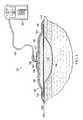
- FIG. 1is sectional view illustrating a reduced-pressure therapy system in accordance with an exemplary embodiment
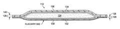
- FIG. 2is a sectional view illustrating a pouch of the reduced-pressure therapy system of FIG. 1 ;
- FIG. 3is an exploded sectional view of the pouch of FIG. 2 .
- FIG. 1is a sectional view of an exemplary embodiment illustrating a therapy system 100 for supplying reduced pressure to a tissue site 106 .
- the therapy system 100may include a dressing 102 in fluid communication with the tissue site 106 , a reduced-pressure source 104 for providing reduced pressure to a tube 120 that may be fluidly coupled to the reduced-pressure source 104 , and a connector 122 that may fluidly couple the tube 120 to the dressing 102 .
- tissue sitein this context broadly refers to a wound or defect located on or within tissue, including but not limited to, bone tissue, adipose tissue, muscle tissue, neural tissue, dermal tissue, vascular tissue, connective tissue, cartilage, tendons, or ligaments.
- a tissue sitemay include chronic, acute, traumatic, subacute, and dehisced wounds, partial-thickness burns, ulcers (such as diabetic, pressure, or venous insufficiency ulcers), flaps, and grafts, for example.
- tissue sitemay also refer to areas of any tissue that are not necessarily wounded or defective, but are instead areas in which it may be desirable to add or promote the growth of additional tissue. For example, reduced pressure may be used in certain tissue areas to grow additional tissue that may be harvested and transplanted to another tissue location.
- a reduced-pressure sourcesuch as the reduced-pressure source 104
- the reduced-pressure sourcemay be housed within or used in conjunction with other components, such as sensors, processing units, alarm indicators, memory, databases, software, display devices, or user interfaces that further facilitate reduced-pressure therapy.
- the pressuretypically ranges between ⁇ 5 mm Hg ( ⁇ 667 Pa) and ⁇ 500 mm Hg ( ⁇ 66.7 kPa). Common therapeutic ranges are between ⁇ 75 mm Hg ( ⁇ 9.9 kPa) and ⁇ 300 mm Hg ( ⁇ 39.9 kPa).
- the fluid mechanics of using a reduced-pressure source to reduce pressure in another component or location, such as within a sealed therapeutic environment,can be mathematically complex.
- the basic principles of fluid mechanics applicable to reduced-pressure therapyare generally well-known to those skilled in the art, and the process of reducing pressure may be described illustratively herein as “delivering,” “distributing,” or “generating” reduced pressure, for example.
- exudates and other fluidsflow toward lower pressure along a fluid path.
- This orientationmay be generally presumed for purposes of describing various features and components of reduced-pressure therapy systems herein.
- downstreamtypically implies something in a fluid path relatively closer to a reduced-pressure source
- upstreamimplies something relatively further away from a reduced-pressure source.
- the fluid pathmay also be reversed in some applications (such as by substituting a positive-pressure source for a reduced-pressure source) and this descriptive convention should not be construed as a limiting convention.
- Reduced pressuregenerally refers to a pressure less than a local ambient pressure, such as the ambient pressure in a local environment external to a sealed therapeutic environment.
- the local ambient pressuremay also be the atmospheric pressure at which a patient is located.
- the pressuremay be less than a hydrostatic pressure associated with tissue at the tissue site. Unless otherwise indicated, values of pressure stated herein are gauge pressures.
- references to increases in reduced pressuretypically refer to a decrease in absolute pressure, while decreases in reduced pressure typically refer to an increase in absolute pressure.
- the components of the therapy system 100may be coupled directly or indirectly. Components may be fluidly coupled to each other to provide a path for transferring fluids (for example, liquid and/or gas) between the components.
- componentsmay be fluidly coupled with a conduit, such as the tube 120 , for example.
- a tubemay be an elongated, cylindrical structure with some flexibility, but the geometry and rigidity may vary.
- componentsmay additionally or alternatively be coupled by virtue of physical proximity, being integral to a single structure, or being formed from the same piece of material. Coupling may also include mechanical, thermal, electrical, or chemical coupling (such as a chemical bond) in some contexts.
- the reduced pressure developed by the reduced-pressure source 104may be delivered through the tube 120 to the connector 122 .
- the connector 122may be a device configured to fluidly couple the reduced-pressure source 104 to the dressing 102 .
- the connector 122may include a flange portion 123 that may couple to the dressing 102 and a port portion that may fluidly couple to the tube 120 .
- the port portionmay be fluidly sealed to the flange portion 123 and may provide fluid communication through the flange portion 123 .
- the connector 122may prevent fluid communication between a sealed therapeutic environment formed by the dressing 102 and the ambient environment.
- the connector 122may allow fluid communication through the dressing 102 between the tissue site 106 and the tube 120 .
- the connector 122may also include a primary filter 121 disposed within a fluid channel of the connector 122 .
- the primary filter 121may be a hydrophobic material substantially filling the fluid channel through the connector 122 and adapted to limit passage of liquids through the connector 122 into the tube 120 .
- the connector 122may be a T.R.A.C.® Pad or Sensa T.R.A.C.® Pad available from Kinetic Concepts, Inc. (KCI) of San Antonio, Tex.
- the connector 122may be a conduit inserted into the dressing 102 .
- the dressing 102may include a manifold 110 adapted to be in fluid communication with the tissue site 106 , a pouch 112 adapted to be in fluid communication between the manifold 110 and the connector 122 , and a drape 108 covering both the manifold 110 and the pouch 112 at the tissue site 106 .
- the manifold 110may be placed within, over, on, or otherwise proximate a tissue site, for example, the tissue site 106 .
- the pouch 112may be placed adjacent the manifold 110 , and the drape 108 may be placed over the manifold 110 and sealed to tissue proximate the tissue site 106 .
- the tissue proximate the tissue site 106may often be undamaged epidermis peripheral to the tissue site 106 .
- the dressing 102can provide the sealed therapeutic environment proximate the tissue site 106 , substantially isolating the tissue site 106 from the external environment.
- the reduced-pressure source 104can reduce the pressure in the sealed therapeutic environment. Reduced pressure applied uniformly through the manifold 110 in the sealed therapeutic environment can induce macrostrain and microstrain in the tissue site 106 , as well as remove exudates and other fluids from the tissue site 106 , which can be collected in the pouch 112 and disposed of properly.
- the manifold 110contacts the tissue site 106 .
- the manifoldmay be partially or fully in contact with the tissue site 106 . If the tissue site 106 extends into tissue from a tissue surface, for example, the manifold 110 may partially or completely fill the tissue site 106 . In other exemplary embodiments, the manifold 110 may be placed over the tissue site 106 .
- the manifold 110may take many forms, and may have many sizes, shapes, or thicknesses depending on a variety of factors, such as the type of treatment being implemented or the nature and size of the tissue site 106 . For example, the size and shape of the manifold 110 may be adapted to the contours of deep and irregular shaped tissue sites.
- the manifold 110may be a substance or structure adapted to distribute reduced pressure to a tissue site, remove fluids from a tissue site, or distribute reduced pressure to and remove fluids from a tissue site.
- a manifoldmay also facilitate delivering fluids to a tissue site, for example, if the fluid path is reversed or a secondary fluid path is provided.
- a manifoldmay include flow channels or pathways that distribute fluids provided to and removed from a tissue site around the manifold. In one exemplary embodiment, the flow channels or pathways may be interconnected to improve distribution of fluids provided to or removed from a tissue site.
- cellular foam, open-cell foam, porous tissue collections, and other porous materialsuch as gauze or felted mat
- cellular foam, open-cell foam, porous tissue collections, and other porous materialgenerally include structural elements arranged to form flow channels.
- Liquids, gels, and other foamsmay also include or be cured to include flow channels.
- the manifold 110may be a porous foam material having interconnected cells or pores adapted to uniformly (or quasi-uniformly) distribute reduced pressure to the tissue site 106 .
- the foam materialmay be either hydrophobic or hydrophilic.
- the manifold 110can be an open-cell, reticulated polyurethane foam such as GranuFoam® dressing available from Kinetic Concepts, Inc. of San Antonio, Tex.
- the manifold 110may also wick fluid away from the tissue site 106 , while continuing to distribute reduced pressure to the tissue site 106 .
- the wicking properties of the manifold 110may draw fluid away from the tissue site 106 by capillary flow or other wicking mechanisms.
- An example of a hydrophilic foamis a polyvinyl alcohol, open-cell foam such as V.A.C. WhiteFoam® dressing available from Kinetic Concepts, Inc. of San Antonio, Tex.
- Other hydrophilic foamsmay include those made from polyether.
- Other foams that may exhibit hydrophilic characteristicsinclude hydrophobic foams that have been treated or coated to provide hydrophilicity.
- the manifold 110may further promote granulation at the tissue site 106 if pressure within the sealed therapeutic environment is reduced.
- any or all of the surfaces of the manifold 110may have an uneven, coarse, or jagged profile that can induce microstrains and stresses at the tissue site 106 if reduced pressure is applied through the manifold 110 to the tissue site 106 .
- the manifold 110may be constructed from bioresorable materials. Suitable bioresorbable materials may include, without limitation, a polymeric blend of polylactic acid (PLA) and polyglycolic acid (PGA). The polymeric blend may also include, without limitation, polycarbonates, polyfumarates, and capralactones.
- the manifold 110may further serve as a scaffold for new cell-growth, or a scaffold material may be used in conjunction with the manifold 110 to promote cell-growth.
- a scaffoldis generally a substance or structure used to enhance or promote the growth of cells or formation of tissue, such as a three-dimensional porous structure that provides a template for cell growth.
- Illustrative examples of scaffold materialsinclude calcium phosphate, collagen, PLA/PGA, coral hydroxy apatites, carbonates, or processed allograft materials.
- the drape 108may include a sealing member.
- a sealing membermay be constructed from a material that can provide a fluid seal between two components or two environments, such as between the sealed therapeutic environment and a local ambient environment.
- a sealing membermay be, for example, an impermeable or semi-permeable, elastomeric material that can provide a seal adequate to maintain a reduced pressure at a tissue site for a given reduced-pressure source. For semi-permeable materials, the permeability generally should be low enough that a desired reduced pressure may be maintained.
- the drape 108may further include an attachment device that may be used to attach the sealing member to an attachment surface, such as undamaged epidermis, a gasket, or another sealing member.
- the attachment devicemay take many forms.
- an attachment devicemay be a medically acceptable, pressure-sensitive adhesive that extends about a periphery of, a portion of, or an entirety of the sealing member.
- Other exemplary embodiments of an attachment devicemay include a double-sided tape, paste, hydrocolloid, hydrogel, silicone gel, organogel, or an acrylic adhesive.
- the pouch 112may include an absorbent member 124 , a first outer layer, such as an upstream layer 126 , and a second outer layer, such as a downstream layer 128 .
- the upstream layer 126 and the downstream layer 128envelop or enclose the absorbent member 124 , which absorbs bodily fluids drawn by the reduced pressure through the upstream layer 126 .
- the absorbent member 124may be formed of or include an absorbent material.
- the absorbent materialfunctions to hold, stabilize, and/or solidify fluids that may be collected from the tissue site 106 .
- the absorbent materialmay be of the type referred to as “hydrogels,” “super-absorbents,” or “hydrocolloids.” If disposed within the dressing 102 , the absorbent material may be formed into fibers or spheres to manifold reduced pressure until the absorbent member 124 becomes saturated. Spaces or voids between the fibers or spheres may allow a reduced pressure that is supplied to the dressing 102 to be transferred within and through the absorbent member 124 to the manifold 110 and the tissue site 106 .
- the absorbent materialmay be Texsus FP2325 having a material density of 800 grams per square meter (gsm).
- the absorbent materialmay be BASF 402C, Technical Absorbents 2317 available from Technical Absorbents (www.techabsorbents.com), sodium polyacrylate super absorbers, cellulosics (carboxy methyl cellulose and salts such as sodium CMC), or alginates.
- the absorbent materialmay be formed of granular absorbent components that may be scatter coated onto a paper substrate. Scatter coating involves spreading a granular absorbent powder uniformly onto a textile substrate, such as paper. The substrate, having the granular absorbent powder disposed thereon, may be passed through an oven to cure the powder and cause the powder to adhere to the paper substrate. The cured granular absorbent powder and substrate may be passed through a calendar machine to provide a smooth uniform surface to the absorbent material.
- the absorbent materials that may be formed using a scatter coating processexperience partial absorbent material loss during handling. The absorbent material loss may occur while positioning the absorbent material proximate the tissue site, while transporting the absorbent material from the manufacturing facility to the facility of use, or during the process of manufacturing a pouch formed solely of absorbent material.
- the upstream layer 126 and the downstream layer 128have perimeter dimensions that may be larger than the perimeter dimensions of the absorbent member 124 so that, if the absorbent member 124 is positioned between the upstream layer 126 and the downstream layer 128 and the center portions of the absorbent member 124 , the upstream layer 126 , and the downstream layer 128 are aligned, the upstream layer 126 and the downstream layer 128 may extend beyond the perimeter of the absorbent member 124 .
- the upstream layer 126 and the downstream layer 128surround the absorbent member 124 .
- Peripheral portions of the upstream layer 126 and the downstream layer 128may be coupled so that the upstream layer 126 and the downstream layer 128 enclose the absorbent member 124 .
- the upstream layer 126 and the downstream layer 128may be coupled by high frequency welding, ultrasonic welding, heat welding, or impulse welding, for example.
- the upstream layer 126 and the downstream layer 128may be coupled by bonding or folding, for example.
- the upstream layer 126may have a first side, such as a hydrophobic side 130 , and a second side, such as a hydrophilic side 132 .
- the hydrophilic side 132may be positioned adjacent the absorbent member 124 such that the hydrophobic side 130 of the upstream layer 126 is also an upstream side of the pouch 112 .
- the upstream layer 126may be formed of non-woven material having a thickness 138 .
- the upstream layer 126may have a polyester fibrous porous structure.
- the upstream layer 126may be porous, but preferably not be perforated.
- the upstream layer 126may have a material density of about 80 gsm. In other exemplary embodiments, the material density may be lower or greater depending on the particular application of the pouch 112 .
- the upstream layer 126may be formed of Libeltex TDL2, for example.
- the hydrophobic side 130may be configured to distribute bodily fluids from the manifold 110 across the upstream surface area of the pouch 112 .
- the hydrophobic side 130may also be referred to as a wicking side, wicking surface, distribution surface, distribution side, or fluid distribution surface.
- the hydrophobic side 130may be a smooth distribution surface configured to move fluid through the upstream layer 126 along a grain of the upstream layer 126 , distributing fluid throughout the upstream layer 126 .
- the hydrophilic side 132may be configured to acquire bodily fluid from the hydrophobic side 130 to aid in bodily fluid movement into the absorbent member 124 .
- the hydrophilic side 132may also be referred to as a fluid acquisition surface, fluid acquisition side, hydrophilic acquisition surface, or hydrophilic acquisition side.
- the hydrophilic side 132may be a fibrous surface and be configured to draw fluid into the upstream layer 126 . While illustrated in FIG. 3 as separate components, the hydrophilic side 132 and the hydrophobic side 130 of the upstream layer 126 may be opposite sides of the upstream layer 126 and are shown as separate components to aid in explanation.
- the downstream layer 128may have a first side, such as a hydrophobic side 134 , and a second side, such as a hydrophilic side 136 .
- the hydrophobic side 134may be positioned adjacent the absorbent member 124 so that the hydrophilic side 136 of the downstream layer 128 is also a downstream side of the pouch 112 .
- the downstream layer 128may be formed of a non-woven material having a thickness 140 .
- the downstream layer 128may have a polyester fibrous porous structure.
- the downstream layer 128may be porous, but preferably not be perforated.
- the downstream layer 128may have a material density of about 150 gsm.
- the material densitymay be lower or greater depending on the particular application of the pouch 112 .
- the material density of the downstream layer 128may be greater than the material density of the upstream layer 126 .
- the thickness 140 of the downstream layer 128may be greater than the thickness 138 of the upstream layer 126 . In the exemplary embodiment illustrated in FIGS. 2 and 3 , the thickness 140 may be about three times greater than the thickness 138 .
- the downstream layer 128may be formed of Libeltex TL4. In other exemplary embodiments, the downstream layer 128 may be formed of Libeltex TDL2.
- the hydrophobic side 134may be disposed adjacent the absorbent member 124 on an opposite side of the absorbent member 124 from the hydrophilic side 132 of the upstream layer 126 .
- the hydrophobic side 134may be configured to distribute bodily fluids not contained by the absorbent member 124 to the hydrophilic side 136 of the downstream layer 128 .
- the hydrophobic side 134may also be referred to as a wicking side, wicking surface, distribution surface, distribution side, or fluid distribution surface.
- the hydrophobic side 134may be a smooth distribution surface configured to move fluid through the downstream layer 128 along a grain of the downstream layer 128 , distributing fluid throughout downstream layer 128 .
- the hydrophilic side 136may be configured to acquire excess bodily fluids wicked by the hydrophobic side 134 from the absorbent member 124 .
- the hydrophilic side 136may also be referred to as a fluid acquisition surface, fluid acquisition side, hydrophilic acquisition surface, or hydrophilic acquisition side.
- the hydrophilic side 136may be a fibrous surface and be configured to draw fluid into the downstream layer 128 . While illustrated in FIG. 3 as separate components, the hydrophobic side 134 and the hydrophilic side 136 may be opposite sides of the downstream layer 128 and may be shown as separate components to aid in explanation of the described exemplary embodiments.
- the upstream layer 126 and the downstream layer 128contain the absorbent member 124 , reducing absorbent material loss during manufacturing, shipping, and use of the pouch 112 .
- Containment of the absorbent materialprevents loss of the granular absorbent components as the pouch 112 may be moved during the manufacturing process.
- containment of the absorbent material in the pouch 112 formed from the upstream layer 126 and the downstream layer 128may reduce loss of the granular absorbent components during use of the pouch 112 , for example, while placing the pouch 112 adjacent the tissue site 106 or positioning the pouch 112 in the therapy system 100 .
- containment of the absorbent materialmay limit migration of the granular absorbent components into the tissue site 106 .
- the pouch 112may aid the manifold 110 in distribution of reduced pressure to the tissue site 106 .
- the upstream layer 126 and the downstream layer 128may enclose the absorbent member 124 , manifold reduced pressure to the tissue site 106 , and wick fluids from the tissue site 106 into the absorbent member 124 .
- the pouch 112may accommodate the increased difficulties of enclosing, manifolding, and wicking that may be experienced when treating a smaller tissue site 106 .
- the pouch 112may prevent the loss of structural integrity associated with using scatter coated absorbent material to form the absorbent member 124 that may often lead to more frequent replacement of the pouch 112 .
- some pouches containing absorbent materialstend to become saturated at the point of fluid entry into the absorbent member itself. If the absorbent material becomes saturated in one area prior to saturation of the absorbent material in other areas, the absorbent material experiences a reduced ability to move fluid from the point of entry to areas of the absorbent material that may be unsaturated. In addition, the amount of reduced pressure distributed to the tissue site may be reduced, decreasing the therapeutic benefits of using reduced pressure. If pouches are decreased in size to be placed adjacent smaller tissue sites or tissue sites that produce smaller amounts of exudate, the pouch's absorbent capability may be further reduced. If the absorbent capability of such pouches is reduced, more frequent dressing changes may be needed, thereby increasing the cost of supplying reduced-pressure therapy.
- the therapy system 100overcomes these shortcomings and others by providing the pouch 112 as described above with respect to FIGS. 2-3 .
- the rate of fluid flow received by the pouch 112may be relatively slow for a relatively long duration.
- Placing the hydrophobic side 130 of the upstream layer 126 adjacent the manifold 110may allow the hydrophobic nature of the hydrophobic side 130 to move the fluid along a grain (not shown) of the hydrophobic side 130 across a width of the upstream layer 126 .
- the fluid movementmay be parallel to the manifold 110 and away from the strongest point of reduced pressure. This wicking action spreads the fluid drawn from the tissue site 106 across a wider area.
- the hydrophilic side 132draws the fluid into the absorbent member 124 .
- the gradient of hydrophilicityincreases from the hydrophobic side 130 to the hydrophilic side 132 as the fluid moves downstream toward the absorbent member 124 .
- the increased thickness 140 and increased material density of the downstream layer 128aid the distribution of reduced pressure to the upstream layer 126 and the manifold 110 .
- the upstream layer 126may have a density of about 80 gsm
- the downstream layer 128may have a density of about 150 gsm so that the relative thickness of the downstream layer 128 to the upstream layer 126 may be about 1.875.
- the relative thickness of the downstream layer 128 in other exemplary embodimentsmay fall in the range from about 1.5 to about 3.0 for other reduced-pressure therapy applications.
- the distribution of reduced pressure by the downstream layer 128aids the wicking action of the hydrophobic side 130 of the upstream layer 126 so that fluids drawn from the tissue site 106 may be more evenly distributed in the dressing 102 .
- more even distribution of the fluids drawn from the tissue site 106provides for more efficient use of the absorbent member 124 , increasing the time between replacement of the dressing 102 , and decreasing costs as fewer dressings may be needed to absorb an equivalent amount of fluid.
- Positioning of the upstream layer 126 and the downstream layer 128may orient grains of the upstream layer 126 and the downstream layer 128 in a manner that increases the efficient use of the absorbent member 124 .
- the hydrophilic side 136may also act as an additional filter mechanism that may aid in preventing blockage of the primary filter 121 of the connector 122 .
- the duration during which the dressing 102 can manifold reduced pressuremay also extended.
- the use of layers that wick fluids and manifold reduced pressureallows for controlled use of the available absorbent material.
- the use of layers to form the pouch with structures of differing hydrophilicityallows for better control of the fluids entering the absorbent member of the pouch.
- the use of layers having different coatweightsallows the properties of the pouch to be matched to the application in a technically better and cost effective solution. The solution disclosed will result in a greater level of absorption before capacity may be reached without requiring additional absorbent material.
- the therapy systemprovides improved materials efficiency, lower cost, and does a better job at manifolding reduced pressure.
- the disclosed exemplary embodimentmay also be used with inline canisters, for example, fluid absorbing pouches or fluid absorbing canisters disposed external to the dressing.
Landscapes
- Health & Medical Sciences (AREA)
- Heart & Thoracic Surgery (AREA)
- Animal Behavior & Ethology (AREA)
- Biomedical Technology (AREA)
- Vascular Medicine (AREA)
- Life Sciences & Earth Sciences (AREA)
- Engineering & Computer Science (AREA)
- General Health & Medical Sciences (AREA)
- Public Health (AREA)
- Veterinary Medicine (AREA)
- Anesthesiology (AREA)
- Hematology (AREA)
- Media Introduction/Drainage Providing Device (AREA)
- External Artificial Organs (AREA)
Abstract
Description
Claims (10)
Priority Applications (2)
| Application Number | Priority Date | Filing Date | Title |
|---|---|---|---|
| US14/150,262US9795724B2 (en) | 2013-01-16 | 2014-01-08 | Dressing with asymmetric absorbent core for negative pressure wound therapy |
| US15/713,390US11045594B2 (en) | 2013-01-16 | 2017-09-22 | Dressing with asymmetric absorbent core for negative pressure wound therapy |
Applications Claiming Priority (2)
| Application Number | Priority Date | Filing Date | Title |
|---|---|---|---|
| US201361753368P | 2013-01-16 | 2013-01-16 | |
| US14/150,262US9795724B2 (en) | 2013-01-16 | 2014-01-08 | Dressing with asymmetric absorbent core for negative pressure wound therapy |
Related Child Applications (1)
| Application Number | Title | Priority Date | Filing Date |
|---|---|---|---|
| US15/713,390DivisionUS11045594B2 (en) | 2013-01-16 | 2017-09-22 | Dressing with asymmetric absorbent core for negative pressure wound therapy |
Publications (2)
| Publication Number | Publication Date |
|---|---|
| US20140200533A1 US20140200533A1 (en) | 2014-07-17 |
| US9795724B2true US9795724B2 (en) | 2017-10-24 |
Family
ID=50102180
Family Applications (2)
| Application Number | Title | Priority Date | Filing Date |
|---|---|---|---|
| US14/150,262Active2034-11-08US9795724B2 (en) | 2013-01-16 | 2014-01-08 | Dressing with asymmetric absorbent core for negative pressure wound therapy |
| US15/713,390Active2035-11-14US11045594B2 (en) | 2013-01-16 | 2017-09-22 | Dressing with asymmetric absorbent core for negative pressure wound therapy |
Family Applications After (1)
| Application Number | Title | Priority Date | Filing Date |
|---|---|---|---|
| US15/713,390Active2035-11-14US11045594B2 (en) | 2013-01-16 | 2017-09-22 | Dressing with asymmetric absorbent core for negative pressure wound therapy |
Country Status (7)
| Country | Link |
|---|---|
| US (2) | US9795724B2 (en) |
| EP (2) | EP3092988B1 (en) |
| JP (2) | JP6392781B2 (en) |
| CN (1) | CN104968309B (en) |
| AU (2) | AU2014207832B2 (en) |
| CA (1) | CA2893670A1 (en) |
| WO (1) | WO2014113253A1 (en) |
Cited By (3)
| Publication number | Priority date | Publication date | Assignee | Title |
|---|---|---|---|---|
| US20180008756A1 (en)* | 2013-01-16 | 2018-01-11 | Kci Licensing, Inc. | Dressing with asymmetric absorbent core for negative pressure wound therapy |
| US20230210700A1 (en)* | 2020-05-25 | 2023-07-06 | Mölnlycke Health Care Ab | A negative pressure wound therapy (npwt) dressing |
| US12336888B2 (en) | 2020-05-25 | 2025-06-24 | Mölnlycke Health Care Ab | Negative pressure wound therapy (NPWT) dressing |
Families Citing this family (85)
| Publication number | Priority date | Publication date | Assignee | Title |
|---|---|---|---|---|
| GB0224986D0 (en) | 2002-10-28 | 2002-12-04 | Smith & Nephew | Apparatus |
| GB0325129D0 (en) | 2003-10-28 | 2003-12-03 | Smith & Nephew | Apparatus in situ |
| US10058642B2 (en) | 2004-04-05 | 2018-08-28 | Bluesky Medical Group Incorporated | Reduced pressure treatment system |
| CA2949821C (en) | 2005-09-06 | 2021-05-18 | Smith & Nephew, Inc. | Self contained wound dressing with micropump |
| US7779625B2 (en) | 2006-05-11 | 2010-08-24 | Kalypto Medical, Inc. | Device and method for wound therapy |
| ES2715605T3 (en) | 2007-11-21 | 2019-06-05 | Smith & Nephew | Wound dressing |
| GB0722820D0 (en) | 2007-11-21 | 2008-01-02 | Smith & Nephew | Vacuum assisted wound dressing |
| EP2214612B1 (en) | 2007-11-21 | 2019-05-01 | Smith & Nephew PLC | Wound dressing |
| US11253399B2 (en) | 2007-12-06 | 2022-02-22 | Smith & Nephew Plc | Wound filling apparatuses and methods |
| GB0723855D0 (en) | 2007-12-06 | 2008-01-16 | Smith & Nephew | Apparatus and method for wound volume measurement |
| US20130096518A1 (en) | 2007-12-06 | 2013-04-18 | Smith & Nephew Plc | Wound filling apparatuses and methods |
| GB2455962A (en) | 2007-12-24 | 2009-07-01 | Ethicon Inc | Reinforced adhesive backing sheet, for plaster |
| AU2009221772B2 (en) | 2008-03-05 | 2015-01-22 | Solventum Intellectual Properties Company | Dressing and method for applying reduced pressure to and collecting and storing fluid from a tissue site |
| US8152785B2 (en) | 2008-03-13 | 2012-04-10 | Tyco Healthcare Group Lp | Vacuum port for vacuum wound therapy |
| US8814842B2 (en) | 2010-03-16 | 2014-08-26 | Kci Licensing, Inc. | Delivery-and-fluid-storage bridges for use with reduced-pressure systems |
| GB201015656D0 (en) | 2010-09-20 | 2010-10-27 | Smith & Nephew | Pressure control apparatus |
| CA2819032C (en) | 2010-11-25 | 2020-06-23 | Smith & Nephew Plc | Composition i-ii and products and uses thereof |
| GB201020005D0 (en) | 2010-11-25 | 2011-01-12 | Smith & Nephew | Composition 1-1 |
| GB2488749A (en) | 2011-01-31 | 2012-09-12 | Systagenix Wound Man Ip Co Bv | Laminated silicone coated wound dressing |
| GB201106491D0 (en) | 2011-04-15 | 2011-06-01 | Systagenix Wound Man Ip Co Bv | Patterened silicone coating |
| GB201108229D0 (en) | 2011-05-17 | 2011-06-29 | Smith & Nephew | Tissue healing |
| US20150159066A1 (en) | 2011-11-25 | 2015-06-11 | Smith & Nephew Plc | Composition, apparatus, kit and method and uses thereof |
| US10940047B2 (en) | 2011-12-16 | 2021-03-09 | Kci Licensing, Inc. | Sealing systems and methods employing a hybrid switchable drape |
| CN103987348B (en) | 2011-12-16 | 2016-05-11 | 凯希特许有限公司 | Releasable Medical Drapes |
| JP6250571B2 (en) | 2012-03-12 | 2017-12-20 | スミス アンド ネフュー ピーエルシーSmith & Nephew Public Limited Company | Pressure reducing apparatus and method |
| AU2013237095B2 (en) | 2012-03-20 | 2017-10-05 | Smith & Nephew Plc | Controlling operation of a reduced pressure therapy system based on dynamic duty cycle threshold determination |
| US9427505B2 (en) | 2012-05-15 | 2016-08-30 | Smith & Nephew Plc | Negative pressure wound therapy apparatus |
| JP6400570B2 (en) | 2012-05-23 | 2018-10-10 | スミス アンド ネフュー ピーエルシーSmith & Nephew Public Limited Company | Apparatus and method for local negative pressure closure therapy |
| CN108186200B (en) | 2012-08-01 | 2021-08-10 | 史密夫及内修公开有限公司 | Wound dressing |
| WO2014020440A1 (en) | 2012-08-01 | 2014-02-06 | Smith & Nephew Plc | Wound dressing |
| AU2013344686B2 (en) | 2012-11-16 | 2018-06-21 | Solventum Intellectual Properties Company | Medical drape with pattern adhesive layers and method of manufacturing same |
| GB201222770D0 (en) | 2012-12-18 | 2013-01-30 | Systagenix Wound Man Ip Co Bv | Wound dressing with adhesive margin |
| GB201317746D0 (en) | 2013-10-08 | 2013-11-20 | Smith & Nephew | PH indicator |
| US20160120706A1 (en) | 2013-03-15 | 2016-05-05 | Smith & Nephew Plc | Wound dressing sealant and use thereof |
| EP2968647B1 (en) | 2013-03-15 | 2022-06-29 | Smith & Nephew plc | Wound dressing sealant and use thereof |
| CN105407932A (en) | 2013-03-15 | 2016-03-16 | 史密夫及内修公开有限公司 | Wound dressing and method of treatment |
| US10695226B2 (en) | 2013-03-15 | 2020-06-30 | Smith & Nephew Plc | Wound dressing and method of treatment |
| EP3038667B1 (en) | 2013-08-26 | 2019-10-09 | KCI Licensing, Inc. | Dressing interface with moisture controlling feature and sealing function |
| US10946124B2 (en) | 2013-10-28 | 2021-03-16 | Kci Licensing, Inc. | Hybrid sealing tape |
| AU2014342903B2 (en) | 2013-10-30 | 2018-09-20 | Solventum Intellectual Properties Company | Dressing with differentially sized perforations |
| EP3527237B1 (en) | 2013-10-30 | 2020-09-09 | KCI Licensing, Inc. | Absorbent conduit and system |
| US9956120B2 (en) | 2013-10-30 | 2018-05-01 | Kci Licensing, Inc. | Dressing with sealing and retention interface |
| EP3062751B1 (en) | 2013-10-30 | 2017-08-09 | KCI Licensing, Inc. | Condensate absorbing and dissipating system |
| EP3110379B1 (en) | 2014-02-28 | 2019-04-03 | KCI Licensing, Inc. | Hybrid drape having a gel-coated perforated mesh |
| US11026844B2 (en) | 2014-03-03 | 2021-06-08 | Kci Licensing, Inc. | Low profile flexible pressure transmission conduit |
| WO2015168681A1 (en) | 2014-05-02 | 2015-11-05 | Kci Licensing, Inc. | Fluid storage devices, systems, and methods |
| JP6640748B2 (en) | 2014-06-05 | 2020-02-05 | ケーシーアイ ライセンシング インコーポレイテッド | Dressing with fluid acquisition and dispensing features |
| US10610414B2 (en) | 2014-06-18 | 2020-04-07 | Smith & Nephew Plc | Wound dressing and method of treatment |
| WO2016100098A1 (en) | 2014-12-17 | 2016-06-23 | Kci Licensing, Inc. | Dressing with offloading capability |
| EP3237032B1 (en) | 2014-12-22 | 2024-08-07 | Smith & Nephew plc | Negative pressure wound therapy apparatus |
| DK3288508T3 (en) | 2015-04-27 | 2020-03-09 | Smith & Nephew | REDUCED PRESSURE DEVICES |
| EP3574877B1 (en) | 2015-05-08 | 2022-08-17 | 3M Innovative Properties Company | Low-acuity dressing with integral pump |
| US10076594B2 (en) | 2015-05-18 | 2018-09-18 | Smith & Nephew Plc | Fluidic connector for negative pressure wound therapy |
| US11413389B2 (en) | 2015-07-07 | 2022-08-16 | Kci Licensing, Inc. | Multi-orientation fluid management |
| EP3741335B1 (en) | 2015-09-01 | 2023-05-24 | KCI Licensing, Inc. | Dressing with increased apposition force |
| EP3349807B1 (en) | 2015-09-17 | 2021-02-24 | 3M Innovative Properties Company | Hybrid silicone and acrylic adhesive cover for use with wound treatment |
| US11364150B2 (en) | 2015-12-30 | 2022-06-21 | Smith & Nephew Plc | Negative pressure wound therapy apparatus |
| US11090196B2 (en) | 2015-12-30 | 2021-08-17 | Smith & Nephew Plc | Absorbent negative pressure wound therapy dressing |
| JP1586116S (en) | 2016-02-29 | 2017-09-19 | ||
| USD796735S1 (en) | 2016-02-29 | 2017-09-05 | Smith & Nephew Plc | Mount apparatus for portable negative pressure apparatus |
| WO2017148824A1 (en) | 2016-03-04 | 2017-09-08 | Smith & Nephew Plc | Negative pressure wound therapy apparatus for post breast surgery wounds |
| EP3426206B1 (en) | 2016-03-07 | 2023-05-10 | Smith & Nephew plc | Wound treatment apparatuses and methods with negative pressure source integrated into wound dressing |
| CA3022184A1 (en) | 2016-04-26 | 2017-11-02 | Smith & Nephew Plc | Wound dressings and methods of use with integrated negative pressure source having a fluid ingress inhibition component |
| WO2017191158A1 (en) | 2016-05-03 | 2017-11-09 | Smith & Nephew Plc | Systems and methods for driving negative pressure sources in negative pressure therapy systems |
| US11096831B2 (en) | 2016-05-03 | 2021-08-24 | Smith & Nephew Plc | Negative pressure wound therapy device activation and control |
| CA3038206A1 (en) | 2016-05-03 | 2017-11-09 | Smith & Nephew Plc | Optimizing power transfer to negative pressure sources in negative pressure therapy systems |
| WO2018037075A1 (en) | 2016-08-25 | 2018-03-01 | Smith & Nephew Plc | Absorbent negative pressure wound therapy dressing |
| EP3519001B1 (en) | 2016-09-30 | 2025-05-21 | Smith & Nephew plc | Negative pressure wound treatment apparatuses and methods with integrated electronics |
| EP3551147B1 (en) | 2016-12-12 | 2023-08-09 | Smith & Nephew PLC | Wound dressing |
| EP3551244A1 (en) | 2016-12-12 | 2019-10-16 | Smith & Nephew PLC | Pressure wound therapy status indication via external device |
| EP3592312B1 (en) | 2017-03-08 | 2024-01-10 | Smith & Nephew plc | Negative pressure wound therapy device control in presence of fault condition |
| JP7121050B2 (en) | 2017-05-09 | 2022-08-17 | スミス アンド ネフュー ピーエルシー | Redundant control of negative pressure wound therapy systems |
| JP7155162B2 (en) | 2017-06-14 | 2022-10-18 | ティージェイ スミス アンド ネフュー リミテッド | Negative pressure wound therapy unit |
| GB201718070D0 (en) | 2017-11-01 | 2017-12-13 | Smith & Nephew | Negative pressure wound treatment apparatuses and methods with integrated electronics |
| CA3074780A1 (en) | 2017-09-13 | 2019-03-21 | Smith & Nephew Plc | Negative pressure wound treatment apparatuses and methods with integrated electronics |
| GB201718072D0 (en) | 2017-11-01 | 2017-12-13 | Smith & Nephew | Negative pressure wound treatment apparatuses and methods with integrated electronics |
| US11497653B2 (en) | 2017-11-01 | 2022-11-15 | Smith & Nephew Plc | Negative pressure wound treatment apparatuses and methods with integrated electronics |
| GB201718054D0 (en) | 2017-11-01 | 2017-12-13 | Smith & Nephew | Sterilization of integrated negative pressure wound treatment apparatuses and sterilization methods |
| US10624794B2 (en) | 2018-02-12 | 2020-04-21 | Healyx Labs, Inc. | Negative pressure wound therapy systems, devices, and methods |
| USD898925S1 (en) | 2018-09-13 | 2020-10-13 | Smith & Nephew Plc | Medical dressing |
| GB201903774D0 (en) | 2019-03-20 | 2019-05-01 | Smith & Nephew | Negative pressure wound treatment apparatuses and methods with integrated electronics |
| GB201907716D0 (en) | 2019-05-31 | 2019-07-17 | Smith & Nephew | Systems and methods for extending operational time of negative pressure wound treatment apparatuses |
| CN110384521A (en)* | 2019-06-26 | 2019-10-29 | 佛山睿源科技有限公司 | A kind of liquid storage core and preparation method thereof |
| GB202001212D0 (en) | 2020-01-29 | 2020-03-11 | Smith & Nephew | Systems and methods for measuring and tracking wound volume |
| ES2984023T3 (en)* | 2020-05-25 | 2024-10-28 | Moelnlycke Health Care Ab | A dressing for negative pressure wound therapy (NPWT) |
Citations (140)
| Publication number | Priority date | Publication date | Assignee | Title |
|---|---|---|---|---|
| US1355846A (en) | 1920-02-06 | 1920-10-19 | David A Rannells | Medical appliance |
| US2547758A (en) | 1949-01-05 | 1951-04-03 | Wilmer B Keeling | Instrument for treating the male urethra |
| US2632443A (en) | 1949-04-18 | 1953-03-24 | Eleanor P Lesher | Surgical dressing |
| GB692578A (en) | 1949-09-13 | 1953-06-10 | Minnesota Mining & Mfg | Improvements in or relating to drape sheets for surgical use |
| US2682873A (en) | 1952-07-30 | 1954-07-06 | Johnson & Johnson | General purpose protective dressing |
| US2910763A (en) | 1955-08-17 | 1959-11-03 | Du Pont | Felt-like products |
| US2969057A (en) | 1957-11-04 | 1961-01-24 | Brady Co W H | Nematodic swab |
| US3066672A (en) | 1960-09-27 | 1962-12-04 | Jr William H Crosby | Method and apparatus for serial sampling of intestinal juice |
| US3367332A (en) | 1965-08-27 | 1968-02-06 | Gen Electric | Product and process for establishing a sterile area of skin |
| US3520300A (en) | 1967-03-15 | 1970-07-14 | Amp Inc | Surgical sponge and suction device |
| US3568675A (en) | 1968-08-30 | 1971-03-09 | Clyde B Harvey | Fistula and penetrating wound dressing |
| US3648692A (en) | 1970-12-07 | 1972-03-14 | Parke Davis & Co | Medical-surgical dressing for burns and the like |
| US3682180A (en) | 1970-06-08 | 1972-08-08 | Coilform Co Inc | Drain clip for surgical drain |
| US3826254A (en) | 1973-02-26 | 1974-07-30 | Verco Ind | Needle or catheter retaining appliance |
| DE2640413A1 (en) | 1976-09-08 | 1978-03-09 | Wolf Gmbh Richard | CATHETER MONITORING DEVICE |
| US4080970A (en) | 1976-11-17 | 1978-03-28 | Miller Thomas J | Post-operative combination dressing and internal drain tube with external shield and tube connector |
| US4096853A (en) | 1975-06-21 | 1978-06-27 | Hoechst Aktiengesellschaft | Device for the introduction of contrast medium into an anus praeter |
| US4139004A (en) | 1977-02-17 | 1979-02-13 | Gonzalez Jr Harry | Bandage apparatus for treating burns |
| US4165748A (en) | 1977-11-07 | 1979-08-28 | Johnson Melissa C | Catheter tube holder |
| US4184510A (en) | 1977-03-15 | 1980-01-22 | Fibra-Sonics, Inc. | Valued device for controlling vacuum in surgery |
| WO1980002182A1 (en) | 1979-04-06 | 1980-10-16 | J Moss | Portable suction device for collecting fluids from a closed wound |
| US4233969A (en) | 1976-11-11 | 1980-11-18 | Lock Peter M | Wound dressing materials |
| US4245630A (en) | 1976-10-08 | 1981-01-20 | T. J. Smith & Nephew, Ltd. | Tearable composite strip of materials |
| US4256109A (en) | 1978-07-10 | 1981-03-17 | Nichols Robert L | Shut off valve for medical suction apparatus |
| US4261363A (en) | 1979-11-09 | 1981-04-14 | C. R. Bard, Inc. | Retention clips for body fluid drains |
| US4275721A (en) | 1978-11-28 | 1981-06-30 | Landstingens Inkopscentral Lic, Ekonomisk Forening | Vein catheter bandage |
| US4284079A (en) | 1979-06-28 | 1981-08-18 | Adair Edwin Lloyd | Method for applying a male incontinence device |
| US4297995A (en) | 1980-06-03 | 1981-11-03 | Key Pharmaceuticals, Inc. | Bandage containing attachment post |
| US4333468A (en) | 1980-08-18 | 1982-06-08 | Geist Robert W | Mesentery tube holder apparatus |
| US4373519A (en) | 1981-06-26 | 1983-02-15 | Minnesota Mining And Manufacturing Company | Composite wound dressing |
| US4382441A (en) | 1978-12-06 | 1983-05-10 | Svedman Paul | Device for treating tissues, for example skin |
| US4392853A (en) | 1981-03-16 | 1983-07-12 | Rudolph Muto | Sterile assembly for protecting and fastening an indwelling device |
| US4392858A (en) | 1981-07-16 | 1983-07-12 | Sherwood Medical Company | Wound drainage device |
| US4419097A (en) | 1981-07-31 | 1983-12-06 | Rexar Industries, Inc. | Attachment for catheter tube |
| EP0100148A1 (en) | 1982-07-06 | 1984-02-08 | Dow Corning Limited | Medical-surgical dressing and a process for the production thereof |
| US4465485A (en) | 1981-03-06 | 1984-08-14 | Becton, Dickinson And Company | Suction canister with unitary shut-off valve and filter features |
| EP0117632A2 (en) | 1983-01-27 | 1984-09-05 | Johnson & Johnson Products Inc. | Adhesive film dressing |
| US4475909A (en) | 1982-05-06 | 1984-10-09 | Eisenberg Melvin I | Male urinary device and method for applying the device |
| US4480638A (en) | 1980-03-11 | 1984-11-06 | Eduard Schmid | Cushion for holding an element of grafted skin |
| US4525166A (en) | 1981-11-21 | 1985-06-25 | Intermedicat Gmbh | Rolled flexible medical suction drainage device |
| US4525374A (en) | 1984-02-27 | 1985-06-25 | Manresa, Inc. | Treating hydrophobic filters to render them hydrophilic |
| US4540412A (en) | 1983-07-14 | 1985-09-10 | The Kendall Company | Device for moist heat therapy |
| US4543100A (en) | 1983-11-01 | 1985-09-24 | Brodsky Stuart A | Catheter and drain tube retainer |
| US4548202A (en) | 1983-06-20 | 1985-10-22 | Ethicon, Inc. | Mesh tissue fasteners |
| US4551139A (en) | 1982-02-08 | 1985-11-05 | Marion Laboratories, Inc. | Method and apparatus for burn wound treatment |
| EP0161865A2 (en) | 1984-05-03 | 1985-11-21 | Smith and Nephew Associated Companies p.l.c. | Adhesive wound dressing |
| US4569348A (en) | 1980-02-22 | 1986-02-11 | Velcro Usa Inc. | Catheter tube holder strap |
| AU550575B2 (en) | 1981-08-07 | 1986-03-27 | Richard Christian Wright | Wound drainage device |
| US4605399A (en) | 1984-12-04 | 1986-08-12 | Complex, Inc. | Transdermal infusion device |
| US4608041A (en) | 1981-10-14 | 1986-08-26 | Frese Nielsen | Device for treatment of wounds in body tissue of patients by exposure to jets of gas |
| US4640688A (en) | 1985-08-23 | 1987-02-03 | Mentor Corporation | Urine collection catheter |
| US4655754A (en) | 1984-11-09 | 1987-04-07 | Stryker Corporation | Vacuum wound drainage system and lipids baffle therefor |
| US4664662A (en) | 1984-08-02 | 1987-05-12 | Smith And Nephew Associated Companies Plc | Wound dressing |
| US4667665A (en) | 1984-08-16 | 1987-05-26 | Colin O'D. Offenhartz | Non-occlusive burn and trauma dressing |
| WO1987004626A1 (en) | 1986-01-31 | 1987-08-13 | Osmond, Roger, L., W. | Suction system for wound and gastro-intestinal drainage |
| US4710165A (en) | 1985-09-16 | 1987-12-01 | Mcneil Charles B | Wearable, variable rate suction/collection device |
| US4733659A (en) | 1986-01-17 | 1988-03-29 | Seton Company | Foam bandage |
| GB2195255A (en) | 1986-09-30 | 1988-04-07 | Vacutec Uk Limited | Method and apparatus for vacuum treatment of an epidermal surface |
| US4743232A (en) | 1986-10-06 | 1988-05-10 | The Clinipad Corporation | Package assembly for plastic film bandage |
| GB2197789A (en) | 1986-11-28 | 1988-06-02 | Smiths Industries Plc | Anti-foaming disinfectants used in surgical suction apparatus |
| US4758220A (en) | 1985-09-26 | 1988-07-19 | Alcon Laboratories, Inc. | Surgical cassette proximity sensing and latching apparatus |
| US4787888A (en) | 1987-06-01 | 1988-11-29 | University Of Connecticut | Disposable piezoelectric polymer bandage for percutaneous delivery of drugs and method for such percutaneous delivery (a) |
| US4826494A (en) | 1984-11-09 | 1989-05-02 | Stryker Corporation | Vacuum wound drainage system |
| US4838883A (en) | 1986-03-07 | 1989-06-13 | Nissho Corporation | Urine-collecting device |
| US4840187A (en) | 1986-09-11 | 1989-06-20 | Bard Limited | Sheath applicator |
| US4863449A (en) | 1987-07-06 | 1989-09-05 | Hollister Incorporated | Adhesive-lined elastic condom cathether |
| US4872450A (en) | 1984-08-17 | 1989-10-10 | Austad Eric D | Wound dressing and method of forming same |
| US4878901A (en) | 1986-10-10 | 1989-11-07 | Sachse Hans Ernst | Condom catheter, a urethral catheter for the prevention of ascending infections |
| GB2220357A (en) | 1988-05-28 | 1990-01-10 | Smiths Industries Plc | Medico-surgical containers |
| US4897081A (en) | 1984-05-25 | 1990-01-30 | Thermedics Inc. | Percutaneous access device |
| US4906233A (en) | 1986-05-29 | 1990-03-06 | Terumo Kabushiki Kaisha | Method of securing a catheter body to a human skin surface |
| US4906240A (en) | 1988-02-01 | 1990-03-06 | Matrix Medica, Inc. | Adhesive-faced porous absorbent sheet and method of making same |
| US4919654A (en) | 1988-08-03 | 1990-04-24 | Kalt Medical Corporation | IV clamp with membrane |
| CA2005436A1 (en) | 1988-12-13 | 1990-06-13 | Glenda G. Kalt | Transparent tracheostomy tube dressing |
| US4941882A (en) | 1987-03-14 | 1990-07-17 | Smith And Nephew Associated Companies, P.L.C. | Adhesive dressing for retaining a cannula on the skin |
| US4953565A (en) | 1986-11-26 | 1990-09-04 | Shunro Tachibana | Endermic application kits for external medicines |
| WO1990010424A1 (en) | 1989-03-16 | 1990-09-20 | Smith & Nephew Plc | Absorbent devices and precursors therefor |
| US4969880A (en) | 1989-04-03 | 1990-11-13 | Zamierowski David S | Wound dressing and treatment method |
| US4985019A (en) | 1988-03-11 | 1991-01-15 | Michelson Gary K | X-ray marker |
| GB2235877A (en) | 1989-09-18 | 1991-03-20 | Antonio Talluri | Closed wound suction apparatus |
| US5037397A (en) | 1985-05-03 | 1991-08-06 | Medical Distributors, Inc. | Universal clamp |
| US5086170A (en) | 1989-01-16 | 1992-02-04 | Roussel Uclaf | Process for the preparation of azabicyclo compounds |
| US5092858A (en) | 1990-03-20 | 1992-03-03 | Becton, Dickinson And Company | Liquid gelling agent distributor device |
| US5100396A (en) | 1989-04-03 | 1992-03-31 | Zamierowski David S | Fluidic connection system and method |
| JPH04129536A (en) | 1990-09-19 | 1992-04-30 | Terumo Corp | Balance device |
| US5134994A (en) | 1990-02-12 | 1992-08-04 | Say Sam L | Field aspirator in a soft pack with externally mounted container |
| US5149331A (en) | 1991-05-03 | 1992-09-22 | Ariel Ferdman | Method and device for wound closure |
| US5167613A (en) | 1992-03-23 | 1992-12-01 | The Kendall Company | Composite vented wound dressing |
| US5176663A (en) | 1987-12-02 | 1993-01-05 | Pal Svedman | Dressing having pad with compressibility limiting elements |
| WO1993009727A1 (en) | 1991-11-14 | 1993-05-27 | Wake Forest University | Method and apparatus for treating tissue damage |
| US5215522A (en) | 1984-07-23 | 1993-06-01 | Ballard Medical Products | Single use medical aspirating device and method |
| US5232453A (en) | 1989-07-14 | 1993-08-03 | E. R. Squibb & Sons, Inc. | Catheter holder |
| US5261893A (en) | 1989-04-03 | 1993-11-16 | Zamierowski David S | Fastening system and method |
| US5278100A (en) | 1991-11-08 | 1994-01-11 | Micron Technology, Inc. | Chemical vapor deposition technique for depositing titanium silicide on semiconductor wafers |
| US5279550A (en) | 1991-12-19 | 1994-01-18 | Gish Biomedical, Inc. | Orthopedic autotransfusion system |
| US5298015A (en) | 1989-07-11 | 1994-03-29 | Nippon Zeon Co., Ltd. | Wound dressing having a porous structure |
| US5342376A (en) | 1993-05-03 | 1994-08-30 | Dermagraphics, Inc. | Inserting device for a barbed tissue connector |
| US5344415A (en) | 1993-06-15 | 1994-09-06 | Deroyal Industries, Inc. | Sterile system for dressing vascular access site |
| DE4306478A1 (en) | 1993-03-02 | 1994-09-08 | Wolfgang Dr Wagner | Drainage device, in particular pleural drainage device, and drainage method |
| WO1994020041A1 (en) | 1993-03-09 | 1994-09-15 | Wake Forest University | Wound treatment employing reduced pressure |
| US5358494A (en) | 1989-07-11 | 1994-10-25 | Svedman Paul | Irrigation dressing |
| US5437622A (en) | 1992-04-29 | 1995-08-01 | Laboratoire Hydrex (Sa) | Transparent adhesive dressing with reinforced starter cuts |
| US5437651A (en) | 1993-09-01 | 1995-08-01 | Research Medical, Inc. | Medical suction apparatus |
| DE29504378U1 (en) | 1995-03-15 | 1995-09-14 | MTG Medizinisch, technische Gerätebau GmbH, 66299 Friedrichsthal | Electronically controlled low-vacuum pump for chest and wound drainage |
| WO1996005873A1 (en) | 1994-08-22 | 1996-02-29 | Kinetic Concepts Inc. | Wound drainage equipment |
| US5527293A (en) | 1989-04-03 | 1996-06-18 | Kinetic Concepts, Inc. | Fastening system and method |
| US5549584A (en) | 1994-02-14 | 1996-08-27 | The Kendall Company | Apparatus for removing fluid from a wound |
| US5556375A (en) | 1994-06-16 | 1996-09-17 | Hercules Incorporated | Wound dressing having a fenestrated base layer |
| US5607388A (en) | 1994-06-16 | 1997-03-04 | Hercules Incorporated | Multi-purpose wound dressing |
| WO1997018007A1 (en) | 1995-11-14 | 1997-05-22 | Kci Medical Limited | Portable wound treatment apparatus |
| WO1999013793A1 (en) | 1997-09-12 | 1999-03-25 | Kci Medical Limited | Surgical drape and suction head for wound treatment |
| US6071267A (en) | 1998-02-06 | 2000-06-06 | Kinetic Concepts, Inc. | Medical patient fluid management interface system and method |
| US6135116A (en) | 1997-07-28 | 2000-10-24 | Kci Licensing, Inc. | Therapeutic method for treating ulcers |
| US6241747B1 (en) | 1993-05-03 | 2001-06-05 | Quill Medical, Inc. | Barbed Bodily tissue connector |
| US6287316B1 (en) | 1999-03-26 | 2001-09-11 | Ethicon, Inc. | Knitted surgical mesh |
| US20020077661A1 (en) | 2000-12-20 | 2002-06-20 | Vahid Saadat | Multi-barbed device for retaining tissue in apposition and methods of use |
| US20020115951A1 (en) | 2001-02-22 | 2002-08-22 | Core Products International, Inc. | Ankle brace providing upper and lower ankle adjustment |
| US20020120185A1 (en) | 2000-05-26 | 2002-08-29 | Kci Licensing, Inc. | System for combined transcutaneous blood gas monitoring and vacuum assisted wound closure |
| US20020143286A1 (en) | 2001-03-05 | 2002-10-03 | Kci Licensing, Inc. | Vacuum assisted wound treatment apparatus and infection identification system and method |
| US6488643B1 (en) | 1998-10-08 | 2002-12-03 | Kci Licensing, Inc. | Wound healing foot wrap |
| US6493568B1 (en) | 1994-07-19 | 2002-12-10 | Kci Licensing, Inc. | Patient interface system |
| AU755496B2 (en) | 1997-09-12 | 2002-12-12 | Kci Licensing, Inc. | Surgical drape and suction head for wound treatment |
| US6673981B1 (en)* | 1999-08-30 | 2004-01-06 | Sca Hygiene Products Ab | Absorbent structure in an absorbent article |
| US20040250969A1 (en)* | 2002-11-07 | 2004-12-16 | Luu Phuong V. | Absorbent sheet exhibiting resistance to moisture penetration |
| US20050143697A1 (en)* | 2002-05-08 | 2005-06-30 | Birgit Riesinger | Absorption body for attachment to the human body |
| US20060079852A1 (en) | 2002-12-31 | 2006-04-13 | Bubb Stephen K | Externally-applied patient interface system and method |
| US20080119802A1 (en)* | 2004-11-24 | 2008-05-22 | Birgit Riesinger | Drainage Device for the Treating Wounds Using a Reduced Pressure |
| JP4129536B2 (en) | 2000-02-24 | 2008-08-06 | ヴェネテック インターナショナル,インコーポレイテッド | Highly compatible catheter anchoring system |
| US20080306456A1 (en)* | 2005-12-14 | 2008-12-11 | Birgit Riesinger | Wound Treatment Device with Elastically Deformable Vacuum-Generating Element |
| WO2009089016A1 (en) | 2008-01-08 | 2009-07-16 | Southeastern Medical Technologies, Llc | A methods and apparatuses for the treatment of wounds with pressures altered from atmospheric |
| US20090204084A1 (en)* | 2005-09-15 | 2009-08-13 | Patrick Lewis Blott | Apparatus |
| US20090227969A1 (en) | 2008-03-05 | 2009-09-10 | Jonathan Paul Jaeb | Dressing and method for applying reduced pressure to and collecting and storing fluid from a tissue site |
| US20090293887A1 (en)* | 2008-05-30 | 2009-12-03 | Robert Peyton Wilkes | Reduced-pressure, compression systems and apparatuses for use on breast tissue |
| US20100069863A1 (en)* | 2008-09-18 | 2010-03-18 | Jonathan Scott Olson | Multi-layer dressings, systems, and methods for applying reduced pressure at a tissue site |
| US20100305490A1 (en)* | 2008-03-05 | 2010-12-02 | Richard Daniel John Coulthard | Dressing and method for applying reduced pressure to and collecting and storing fluid from a tissue site |
| WO2011049562A1 (en) | 2009-10-20 | 2011-04-28 | Kci Licensing, Inc. | Dressing reduced-pressure indicators, systems, and methods |
| US20110313373A1 (en)* | 2004-11-02 | 2011-12-22 | Birgit Riesinger | Device for the treatment of wounds using a vacuum |
| US20120143157A1 (en) | 2004-11-02 | 2012-06-07 | Birgit Riesinger | Multi-component dressing for wound treatment on the human or animal body with application of reduced pressure |
| WO2012112204A1 (en) | 2011-02-14 | 2012-08-23 | Kci Licensing, Inc. | Reduced-pressure dressings, systems, and methods for use with linear wounds |
| EP2578193A1 (en) | 2010-06-01 | 2013-04-10 | Zuiko Corporation | Surface sheet for wound dressing and wound dressing |
Family Cites Families (16)
| Publication number | Priority date | Publication date | Assignee | Title |
|---|---|---|---|---|
| US6461716B1 (en) | 1999-06-24 | 2002-10-08 | The Procter & Gamble Company | Apertured webs having permanent hydrophilicity and absorbent articles using such webs |
| CN1443055A (en)* | 2000-05-19 | 2003-09-17 | 金伯利-克拉克环球有限公司 | Topsheet and transfer layer for absorbent article |
| US7846141B2 (en) | 2002-09-03 | 2010-12-07 | Bluesky Medical Group Incorporated | Reduced pressure treatment system |
| GB0224986D0 (en) | 2002-10-28 | 2002-12-04 | Smith & Nephew | Apparatus |
| GB0325126D0 (en) | 2003-10-28 | 2003-12-03 | Smith & Nephew | Apparatus with heat |
| GB0325120D0 (en) | 2003-10-28 | 2003-12-03 | Smith & Nephew | Apparatus with actives |
| JP4303143B2 (en)* | 2003-12-25 | 2009-07-29 | ユニ・チャーム株式会社 | Panty liner |
| US7909805B2 (en) | 2004-04-05 | 2011-03-22 | Bluesky Medical Group Incorporated | Flexible reduced pressure treatment appliance |
| US8529548B2 (en) | 2004-04-27 | 2013-09-10 | Smith & Nephew Plc | Wound treatment apparatus and method |
| US8021347B2 (en) | 2008-07-21 | 2011-09-20 | Tyco Healthcare Group Lp | Thin film wound dressing |
| US8007481B2 (en) | 2008-07-17 | 2011-08-30 | Tyco Healthcare Group Lp | Subatmospheric pressure mechanism for wound therapy system |
| US8251979B2 (en) | 2009-05-11 | 2012-08-28 | Tyco Healthcare Group Lp | Orientation independent canister for a negative pressure wound therapy device |
| US8216198B2 (en) | 2009-01-09 | 2012-07-10 | Tyco Healthcare Group Lp | Canister for receiving wound exudate in a negative pressure therapy system |
| US20130012902A1 (en)* | 2010-02-26 | 2013-01-10 | Vir I Kinda Ab | Wound dressing comprising a superabsorbing substance |
| US8469935B2 (en)* | 2010-03-11 | 2013-06-25 | Kci Licensing, Inc. | Abdominal treatment systems, delivery devices, and methods |
| AU2014207832B2 (en)* | 2013-01-16 | 2018-03-15 | Kci Licensing, Inc. | Dressing with asymmetric absorbent core for negative pressure wound therapy |
- 2014
- 2014-01-08AUAU2014207832Apatent/AU2014207832B2/ennot_activeCeased
- 2014-01-08CNCN201480004131.5Apatent/CN104968309B/enactiveActive
- 2014-01-08EPEP16176518.5Apatent/EP3092988B1/enactiveActive
- 2014-01-08JPJP2015552746Apatent/JP6392781B2/enactiveActive
- 2014-01-08WOPCT/US2014/010704patent/WO2014113253A1/enactiveApplication Filing
- 2014-01-08USUS14/150,262patent/US9795724B2/enactiveActive
- 2014-01-08CACA2893670Apatent/CA2893670A1/ennot_activeAbandoned
- 2014-01-08EPEP14704411.9Apatent/EP2945584B1/enactiveActive
- 2017
- 2017-09-22USUS15/713,390patent/US11045594B2/enactiveActive
- 2018
- 2018-06-12AUAU2018204175Apatent/AU2018204175B2/ennot_activeCeased
- 2018-08-23JPJP2018155994Apatent/JP6691941B2/enactiveActive
Patent Citations (150)
| Publication number | Priority date | Publication date | Assignee | Title |
|---|---|---|---|---|
| US1355846A (en) | 1920-02-06 | 1920-10-19 | David A Rannells | Medical appliance |
| US2547758A (en) | 1949-01-05 | 1951-04-03 | Wilmer B Keeling | Instrument for treating the male urethra |
| US2632443A (en) | 1949-04-18 | 1953-03-24 | Eleanor P Lesher | Surgical dressing |
| GB692578A (en) | 1949-09-13 | 1953-06-10 | Minnesota Mining & Mfg | Improvements in or relating to drape sheets for surgical use |
| US2682873A (en) | 1952-07-30 | 1954-07-06 | Johnson & Johnson | General purpose protective dressing |
| US2910763A (en) | 1955-08-17 | 1959-11-03 | Du Pont | Felt-like products |
| US2969057A (en) | 1957-11-04 | 1961-01-24 | Brady Co W H | Nematodic swab |
| US3066672A (en) | 1960-09-27 | 1962-12-04 | Jr William H Crosby | Method and apparatus for serial sampling of intestinal juice |
| US3367332A (en) | 1965-08-27 | 1968-02-06 | Gen Electric | Product and process for establishing a sterile area of skin |
| US3520300A (en) | 1967-03-15 | 1970-07-14 | Amp Inc | Surgical sponge and suction device |
| US3568675A (en) | 1968-08-30 | 1971-03-09 | Clyde B Harvey | Fistula and penetrating wound dressing |
| US3682180A (en) | 1970-06-08 | 1972-08-08 | Coilform Co Inc | Drain clip for surgical drain |
| US3648692A (en) | 1970-12-07 | 1972-03-14 | Parke Davis & Co | Medical-surgical dressing for burns and the like |
| US3826254A (en) | 1973-02-26 | 1974-07-30 | Verco Ind | Needle or catheter retaining appliance |
| US4096853A (en) | 1975-06-21 | 1978-06-27 | Hoechst Aktiengesellschaft | Device for the introduction of contrast medium into an anus praeter |
| DE2640413A1 (en) | 1976-09-08 | 1978-03-09 | Wolf Gmbh Richard | CATHETER MONITORING DEVICE |
| US4245630A (en) | 1976-10-08 | 1981-01-20 | T. J. Smith & Nephew, Ltd. | Tearable composite strip of materials |
| US4233969A (en) | 1976-11-11 | 1980-11-18 | Lock Peter M | Wound dressing materials |
| US4080970A (en) | 1976-11-17 | 1978-03-28 | Miller Thomas J | Post-operative combination dressing and internal drain tube with external shield and tube connector |
| US4139004A (en) | 1977-02-17 | 1979-02-13 | Gonzalez Jr Harry | Bandage apparatus for treating burns |
| US4184510A (en) | 1977-03-15 | 1980-01-22 | Fibra-Sonics, Inc. | Valued device for controlling vacuum in surgery |
| US4165748A (en) | 1977-11-07 | 1979-08-28 | Johnson Melissa C | Catheter tube holder |
| US4256109A (en) | 1978-07-10 | 1981-03-17 | Nichols Robert L | Shut off valve for medical suction apparatus |
| US4275721A (en) | 1978-11-28 | 1981-06-30 | Landstingens Inkopscentral Lic, Ekonomisk Forening | Vein catheter bandage |
| US4382441A (en) | 1978-12-06 | 1983-05-10 | Svedman Paul | Device for treating tissues, for example skin |
| WO1980002182A1 (en) | 1979-04-06 | 1980-10-16 | J Moss | Portable suction device for collecting fluids from a closed wound |
| US4284079A (en) | 1979-06-28 | 1981-08-18 | Adair Edwin Lloyd | Method for applying a male incontinence device |
| US4261363A (en) | 1979-11-09 | 1981-04-14 | C. R. Bard, Inc. | Retention clips for body fluid drains |
| US4569348A (en) | 1980-02-22 | 1986-02-11 | Velcro Usa Inc. | Catheter tube holder strap |
| US4480638A (en) | 1980-03-11 | 1984-11-06 | Eduard Schmid | Cushion for holding an element of grafted skin |
| US4297995A (en) | 1980-06-03 | 1981-11-03 | Key Pharmaceuticals, Inc. | Bandage containing attachment post |
| US4333468A (en) | 1980-08-18 | 1982-06-08 | Geist Robert W | Mesentery tube holder apparatus |
| US4465485A (en) | 1981-03-06 | 1984-08-14 | Becton, Dickinson And Company | Suction canister with unitary shut-off valve and filter features |
| US4392853A (en) | 1981-03-16 | 1983-07-12 | Rudolph Muto | Sterile assembly for protecting and fastening an indwelling device |
| US4373519A (en) | 1981-06-26 | 1983-02-15 | Minnesota Mining And Manufacturing Company | Composite wound dressing |
| US4392858A (en) | 1981-07-16 | 1983-07-12 | Sherwood Medical Company | Wound drainage device |
| US4419097A (en) | 1981-07-31 | 1983-12-06 | Rexar Industries, Inc. | Attachment for catheter tube |
| AU550575B2 (en) | 1981-08-07 | 1986-03-27 | Richard Christian Wright | Wound drainage device |
| US4608041A (en) | 1981-10-14 | 1986-08-26 | Frese Nielsen | Device for treatment of wounds in body tissue of patients by exposure to jets of gas |
| US4525166A (en) | 1981-11-21 | 1985-06-25 | Intermedicat Gmbh | Rolled flexible medical suction drainage device |
| US4551139A (en) | 1982-02-08 | 1985-11-05 | Marion Laboratories, Inc. | Method and apparatus for burn wound treatment |
| US4475909A (en) | 1982-05-06 | 1984-10-09 | Eisenberg Melvin I | Male urinary device and method for applying the device |
| EP0100148A1 (en) | 1982-07-06 | 1984-02-08 | Dow Corning Limited | Medical-surgical dressing and a process for the production thereof |
| EP0117632A2 (en) | 1983-01-27 | 1984-09-05 | Johnson & Johnson Products Inc. | Adhesive film dressing |
| US4548202A (en) | 1983-06-20 | 1985-10-22 | Ethicon, Inc. | Mesh tissue fasteners |
| US4540412A (en) | 1983-07-14 | 1985-09-10 | The Kendall Company | Device for moist heat therapy |
| US4543100A (en) | 1983-11-01 | 1985-09-24 | Brodsky Stuart A | Catheter and drain tube retainer |
| US4525374A (en) | 1984-02-27 | 1985-06-25 | Manresa, Inc. | Treating hydrophobic filters to render them hydrophilic |
| EP0161865A2 (en) | 1984-05-03 | 1985-11-21 | Smith and Nephew Associated Companies p.l.c. | Adhesive wound dressing |
| US4897081A (en) | 1984-05-25 | 1990-01-30 | Thermedics Inc. | Percutaneous access device |
| US5215522A (en) | 1984-07-23 | 1993-06-01 | Ballard Medical Products | Single use medical aspirating device and method |
| US4664662A (en) | 1984-08-02 | 1987-05-12 | Smith And Nephew Associated Companies Plc | Wound dressing |
| US4667665A (en) | 1984-08-16 | 1987-05-26 | Colin O'D. Offenhartz | Non-occlusive burn and trauma dressing |
| US4872450A (en) | 1984-08-17 | 1989-10-10 | Austad Eric D | Wound dressing and method of forming same |
| US4655754A (en) | 1984-11-09 | 1987-04-07 | Stryker Corporation | Vacuum wound drainage system and lipids baffle therefor |
| US4826494A (en) | 1984-11-09 | 1989-05-02 | Stryker Corporation | Vacuum wound drainage system |
| US4605399A (en) | 1984-12-04 | 1986-08-12 | Complex, Inc. | Transdermal infusion device |
| US5037397A (en) | 1985-05-03 | 1991-08-06 | Medical Distributors, Inc. | Universal clamp |
| US4640688A (en) | 1985-08-23 | 1987-02-03 | Mentor Corporation | Urine collection catheter |
| US4710165A (en) | 1985-09-16 | 1987-12-01 | Mcneil Charles B | Wearable, variable rate suction/collection device |
| US4758220A (en) | 1985-09-26 | 1988-07-19 | Alcon Laboratories, Inc. | Surgical cassette proximity sensing and latching apparatus |
| US4733659A (en) | 1986-01-17 | 1988-03-29 | Seton Company | Foam bandage |
| WO1987004626A1 (en) | 1986-01-31 | 1987-08-13 | Osmond, Roger, L., W. | Suction system for wound and gastro-intestinal drainage |
| US4838883A (en) | 1986-03-07 | 1989-06-13 | Nissho Corporation | Urine-collecting device |
| US4906233A (en) | 1986-05-29 | 1990-03-06 | Terumo Kabushiki Kaisha | Method of securing a catheter body to a human skin surface |
| US4840187A (en) | 1986-09-11 | 1989-06-20 | Bard Limited | Sheath applicator |
| GB2195255A (en) | 1986-09-30 | 1988-04-07 | Vacutec Uk Limited | Method and apparatus for vacuum treatment of an epidermal surface |
| US4743232A (en) | 1986-10-06 | 1988-05-10 | The Clinipad Corporation | Package assembly for plastic film bandage |
| US4878901A (en) | 1986-10-10 | 1989-11-07 | Sachse Hans Ernst | Condom catheter, a urethral catheter for the prevention of ascending infections |
| US4953565A (en) | 1986-11-26 | 1990-09-04 | Shunro Tachibana | Endermic application kits for external medicines |
| GB2197789A (en) | 1986-11-28 | 1988-06-02 | Smiths Industries Plc | Anti-foaming disinfectants used in surgical suction apparatus |
| US4941882A (en) | 1987-03-14 | 1990-07-17 | Smith And Nephew Associated Companies, P.L.C. | Adhesive dressing for retaining a cannula on the skin |
| US4787888A (en) | 1987-06-01 | 1988-11-29 | University Of Connecticut | Disposable piezoelectric polymer bandage for percutaneous delivery of drugs and method for such percutaneous delivery (a) |
| US4863449A (en) | 1987-07-06 | 1989-09-05 | Hollister Incorporated | Adhesive-lined elastic condom cathether |
| US5176663A (en) | 1987-12-02 | 1993-01-05 | Pal Svedman | Dressing having pad with compressibility limiting elements |
| US4906240A (en) | 1988-02-01 | 1990-03-06 | Matrix Medica, Inc. | Adhesive-faced porous absorbent sheet and method of making same |
| US4985019A (en) | 1988-03-11 | 1991-01-15 | Michelson Gary K | X-ray marker |
| GB2220357A (en) | 1988-05-28 | 1990-01-10 | Smiths Industries Plc | Medico-surgical containers |
| EP0358302A2 (en) | 1988-05-28 | 1990-03-14 | Smiths Industries Public Limited Company | Medico-surgical suction container |
| US4919654A (en) | 1988-08-03 | 1990-04-24 | Kalt Medical Corporation | IV clamp with membrane |
| CA2005436A1 (en) | 1988-12-13 | 1990-06-13 | Glenda G. Kalt | Transparent tracheostomy tube dressing |
| US5086170A (en) | 1989-01-16 | 1992-02-04 | Roussel Uclaf | Process for the preparation of azabicyclo compounds |
| WO1990010424A1 (en) | 1989-03-16 | 1990-09-20 | Smith & Nephew Plc | Absorbent devices and precursors therefor |
| US4969880A (en) | 1989-04-03 | 1990-11-13 | Zamierowski David S | Wound dressing and treatment method |
| US5100396A (en) | 1989-04-03 | 1992-03-31 | Zamierowski David S | Fluidic connection system and method |
| US5527293A (en) | 1989-04-03 | 1996-06-18 | Kinetic Concepts, Inc. | Fastening system and method |
| US5261893A (en) | 1989-04-03 | 1993-11-16 | Zamierowski David S | Fastening system and method |
| US5358494A (en) | 1989-07-11 | 1994-10-25 | Svedman Paul | Irrigation dressing |
| US5298015A (en) | 1989-07-11 | 1994-03-29 | Nippon Zeon Co., Ltd. | Wound dressing having a porous structure |
| US5232453A (en) | 1989-07-14 | 1993-08-03 | E. R. Squibb & Sons, Inc. | Catheter holder |
| GB2235877A (en) | 1989-09-18 | 1991-03-20 | Antonio Talluri | Closed wound suction apparatus |
| US5134994A (en) | 1990-02-12 | 1992-08-04 | Say Sam L | Field aspirator in a soft pack with externally mounted container |
| US5092858A (en) | 1990-03-20 | 1992-03-03 | Becton, Dickinson And Company | Liquid gelling agent distributor device |
| JPH04129536A (en) | 1990-09-19 | 1992-04-30 | Terumo Corp | Balance device |
| US5149331A (en) | 1991-05-03 | 1992-09-22 | Ariel Ferdman | Method and device for wound closure |
| US5278100A (en) | 1991-11-08 | 1994-01-11 | Micron Technology, Inc. | Chemical vapor deposition technique for depositing titanium silicide on semiconductor wafers |
| US5636643A (en) | 1991-11-14 | 1997-06-10 | Wake Forest University | Wound treatment employing reduced pressure |
| WO1993009727A1 (en) | 1991-11-14 | 1993-05-27 | Wake Forest University | Method and apparatus for treating tissue damage |
| US5645081A (en) | 1991-11-14 | 1997-07-08 | Wake Forest University | Method of treating tissue damage and apparatus for same |
| US5279550A (en) | 1991-12-19 | 1994-01-18 | Gish Biomedical, Inc. | Orthopedic autotransfusion system |
| US5167613A (en) | 1992-03-23 | 1992-12-01 | The Kendall Company | Composite vented wound dressing |
| US5437622A (en) | 1992-04-29 | 1995-08-01 | Laboratoire Hydrex (Sa) | Transparent adhesive dressing with reinforced starter cuts |
| DE4306478A1 (en) | 1993-03-02 | 1994-09-08 | Wolfgang Dr Wagner | Drainage device, in particular pleural drainage device, and drainage method |
| WO1994020041A1 (en) | 1993-03-09 | 1994-09-15 | Wake Forest University | Wound treatment employing reduced pressure |
| US6241747B1 (en) | 1993-05-03 | 2001-06-05 | Quill Medical, Inc. | Barbed Bodily tissue connector |
| US5342376A (en) | 1993-05-03 | 1994-08-30 | Dermagraphics, Inc. | Inserting device for a barbed tissue connector |
| US5344415A (en) | 1993-06-15 | 1994-09-06 | Deroyal Industries, Inc. | Sterile system for dressing vascular access site |
| US5437651A (en) | 1993-09-01 | 1995-08-01 | Research Medical, Inc. | Medical suction apparatus |
| US5549584A (en) | 1994-02-14 | 1996-08-27 | The Kendall Company | Apparatus for removing fluid from a wound |
| US5556375A (en) | 1994-06-16 | 1996-09-17 | Hercules Incorporated | Wound dressing having a fenestrated base layer |
| US5607388A (en) | 1994-06-16 | 1997-03-04 | Hercules Incorporated | Multi-purpose wound dressing |
| US6493568B1 (en) | 1994-07-19 | 2002-12-10 | Kci Licensing, Inc. | Patient interface system |
| WO1996005873A1 (en) | 1994-08-22 | 1996-02-29 | Kinetic Concepts Inc. | Wound drainage equipment |
| DE29504378U1 (en) | 1995-03-15 | 1995-09-14 | MTG Medizinisch, technische Gerätebau GmbH, 66299 Friedrichsthal | Electronically controlled low-vacuum pump for chest and wound drainage |
| WO1997018007A1 (en) | 1995-11-14 | 1997-05-22 | Kci Medical Limited | Portable wound treatment apparatus |
| US6135116A (en) | 1997-07-28 | 2000-10-24 | Kci Licensing, Inc. | Therapeutic method for treating ulcers |
| GB2333965A (en) | 1997-09-12 | 1999-08-11 | Kci Medical Ltd | Surgical drape |
| US6553998B2 (en) | 1997-09-12 | 2003-04-29 | Kci Licensing, Inc. | Surgical drape and suction head for wound treatment |
| GB2329127B (en) | 1997-09-12 | 2000-08-16 | Kci Medical Ltd | Surgical drape and suction head for wound treatment |
| US6814079B2 (en) | 1997-09-12 | 2004-11-09 | Kci Licensing, Inc. | Surgical drape and suction head for wound treatment |
| US6345623B1 (en) | 1997-09-12 | 2002-02-12 | Keith Patrick Heaton | Surgical drape and suction head for wound treatment |
| AU745271B2 (en) | 1997-09-12 | 2002-03-14 | Kci Licensing, Inc. | Surgical drape and suction head for wound treatment |
| EP1018967B1 (en) | 1997-09-12 | 2004-08-18 | KCI Licensing, Inc. | Suction head for wound treatment and combination with a surgical drape |
| AU755496B2 (en) | 1997-09-12 | 2002-12-12 | Kci Licensing, Inc. | Surgical drape and suction head for wound treatment |
| WO1999013793A1 (en) | 1997-09-12 | 1999-03-25 | Kci Medical Limited | Surgical drape and suction head for wound treatment |
| US6071267A (en) | 1998-02-06 | 2000-06-06 | Kinetic Concepts, Inc. | Medical patient fluid management interface system and method |
| US6488643B1 (en) | 1998-10-08 | 2002-12-03 | Kci Licensing, Inc. | Wound healing foot wrap |
| US6287316B1 (en) | 1999-03-26 | 2001-09-11 | Ethicon, Inc. | Knitted surgical mesh |
| US6673981B1 (en)* | 1999-08-30 | 2004-01-06 | Sca Hygiene Products Ab | Absorbent structure in an absorbent article |
| JP4129536B2 (en) | 2000-02-24 | 2008-08-06 | ヴェネテック インターナショナル,インコーポレイテッド | Highly compatible catheter anchoring system |
| US20020120185A1 (en) | 2000-05-26 | 2002-08-29 | Kci Licensing, Inc. | System for combined transcutaneous blood gas monitoring and vacuum assisted wound closure |
| US20020077661A1 (en) | 2000-12-20 | 2002-06-20 | Vahid Saadat | Multi-barbed device for retaining tissue in apposition and methods of use |
| US20020115951A1 (en) | 2001-02-22 | 2002-08-22 | Core Products International, Inc. | Ankle brace providing upper and lower ankle adjustment |
| US20020143286A1 (en) | 2001-03-05 | 2002-10-03 | Kci Licensing, Inc. | Vacuum assisted wound treatment apparatus and infection identification system and method |
| US20050143697A1 (en)* | 2002-05-08 | 2005-06-30 | Birgit Riesinger | Absorption body for attachment to the human body |
| US20040250969A1 (en)* | 2002-11-07 | 2004-12-16 | Luu Phuong V. | Absorbent sheet exhibiting resistance to moisture penetration |
| US20060079852A1 (en) | 2002-12-31 | 2006-04-13 | Bubb Stephen K | Externally-applied patient interface system and method |
| US20110313373A1 (en)* | 2004-11-02 | 2011-12-22 | Birgit Riesinger | Device for the treatment of wounds using a vacuum |
| US20120143157A1 (en) | 2004-11-02 | 2012-06-07 | Birgit Riesinger | Multi-component dressing for wound treatment on the human or animal body with application of reduced pressure |
| US20080119802A1 (en)* | 2004-11-24 | 2008-05-22 | Birgit Riesinger | Drainage Device for the Treating Wounds Using a Reduced Pressure |
| US20090204084A1 (en)* | 2005-09-15 | 2009-08-13 | Patrick Lewis Blott | Apparatus |
| US20080306456A1 (en)* | 2005-12-14 | 2008-12-11 | Birgit Riesinger | Wound Treatment Device with Elastically Deformable Vacuum-Generating Element |
| WO2009089016A1 (en) | 2008-01-08 | 2009-07-16 | Southeastern Medical Technologies, Llc | A methods and apparatuses for the treatment of wounds with pressures altered from atmospheric |
| US20090227969A1 (en) | 2008-03-05 | 2009-09-10 | Jonathan Paul Jaeb | Dressing and method for applying reduced pressure to and collecting and storing fluid from a tissue site |
| US20100305490A1 (en)* | 2008-03-05 | 2010-12-02 | Richard Daniel John Coulthard | Dressing and method for applying reduced pressure to and collecting and storing fluid from a tissue site |
| US20090293887A1 (en)* | 2008-05-30 | 2009-12-03 | Robert Peyton Wilkes | Reduced-pressure, compression systems and apparatuses for use on breast tissue |
| US20100069863A1 (en)* | 2008-09-18 | 2010-03-18 | Jonathan Scott Olson | Multi-layer dressings, systems, and methods for applying reduced pressure at a tissue site |
| WO2011049562A1 (en) | 2009-10-20 | 2011-04-28 | Kci Licensing, Inc. | Dressing reduced-pressure indicators, systems, and methods |
| EP2578193A1 (en) | 2010-06-01 | 2013-04-10 | Zuiko Corporation | Surface sheet for wound dressing and wound dressing |
| WO2012112204A1 (en) | 2011-02-14 | 2012-08-23 | Kci Licensing, Inc. | Reduced-pressure dressings, systems, and methods for use with linear wounds |
Non-Patent Citations (42)
| Title |
|---|
| A.A. Safronov, Dissertation Abstract, Vacuum Therapy of Trophic Ulcers of the Lower Leg with Simultaneous Autoplasty of the Skin (Central Scientific Research Institute of Traumatology and Orthopedics, Moscow, U.S.S.R. 1967) (copy and certified translation). |
| Arnljots, Björn et al.: "Irrigation Treatment in Split-Thickness Skin Grafting of Intractable Leg Ulcers", Scand J. Plast Reconstr. Surg., vol. 19, 1985, pp. 211-213. |
| C.E. Tennant, "The Use of Hypermia in the Postoperative Treatment of Lesions of the Extremities and Thorax," Journal of the American Medical Association 64 (1915), pp. 1548-1549. |
| Chariker, Mark E., M.D., et al; "Effective Management of incisional and cutaneous fistulae with closed suction wound drainage"; Contemporary Surgery, vol. 34, Jun. 1989, pp. 59-63. |
| Chinn, Steven D. et al.: "Closed Wound Suction Drainage", The Journal of Foot Surgery, vol. 24, No. 1, 1985, pp. 76-81. |
| D.E. Tribble, "An Improved Sump Drain-Irrigation Device of Simple Construction," Archives of Surgery 105 (1972) pp. 511-513. |
| Dattilo, Philip P., Jr., et al; "Medical Textiles: Application of an Absorbable Barbed Bi-directional Surgical Suture"; Journal of Textile and Apparel, Technology and Management, vol. 2, Issue 2, Spring 2002, pp. 1-5. |
| Davydov, Yu. A., et al; "Bacteriological and Cytological Assessment of Vacuum Therapy for Purulent Wounds"; Vestnik Khirurgi, Oct. 1988, pp. 48-52, and 8 page English translation thereof. |
| Davydov, Yu. A., et al; "Concepts for the Clinical-Biological Management of the Wound Process in the Treatment of Purulent Wounds by Means of Vacuum Therapy"; Vestnik Khirurgi, Jul. 7, 1980, pp. 132-136, and 8 page English translation thereof. |
| Davydov, Yu. A., et al; "Vacuum Therapy in the Treatment of Purulent Lactation Mastitis"; Vestnik Khirurgi, May 14, 1986, pp. 66-70, and 9 page English translation thereof. |
| Egnell Minor, Instruction Book, First Edition, 300 7502, Feb. 1975, pp. 24. |
| Egnell Minor: Addition to the Users Manual Concerning Overflow Protection—Concerns all Egnell Pumps, Feb. 3, 1983, p. 1. |
| Extended European Search Report corresponding to EP16176518.5, dated Oct. 4, 2016. |
| F.E. Johnson, "An Improved Technique for Skin Graft Placement Using a Suction Drain," Surgery, Gynecology, and Obstetrics 159 (1984), pp. 584-585. |
| G. {hacek over (Z)}ivadinovic, V. ukić, {hacek over (Z)}. Maksimović, . Radak, and P. Pe{hacek over (s)}ka, "Vacuum Therapy in the Treatment of Peripheral Blood Vessels," Timok Medical Journal 11 (1986), pp. 161-164 (copy and certified translation). |
| George V. Letsou, MD., et al; "Stimulation of Adenylate Cyclase Activity in Cultured Endothelial Cells Subjected to Cyclic Stretch"; Journal of Cardiovascular Surgery, vol. 31, 1990, pp. 634-639. |
| International Search Report and Written Opinion for corresponding PCT/US2014/010704 dated Mar. 25, 2014. |
| International Search Report and Written Opinion for corresponding PCT/US2014/048081 dated Nov. 14, 2014. |
| International Search Report for PCT International Application PCT/GB95/01983; dated Nov. 23, 1995. |
| James H. Blackburn, II, MD, et al; "Negative-Pressure Dressings as a Bolster for Skin Grafts"; Annals of Plastic Surgery, vol. 40, No. 5, May 1998, pp. 453-457. |
| John Masters; "Reliable, Inexpensive and Simple Suction Dressings"; Letters to the Editor, British Journal of Plastic Surgery, 1998, vol. 51 (3), p. 267; Elsevier Science/The British Association of Plastic Surgeons, UK. |
| K.F. Jeter, T.E. Tintle, and M. Chariker, "Managing Draining Wounds and Fistulae: New and Established Methods," Chronic Wound Care, edited by D. Krasner (Health Management Publications, Inc., King of Prussia, PA 1990), pp. 240-246. |
| Kostyuchenok, B.M., et al; "Vacuum Treatment in the Surgical Management of Purulent Wounds"; Vestnik Khirurgi, Sep. 1986, pp. 18-21 and 6 page English translation thereof. |
| Louis C. Argenta, MD and Michael J. Morykwas, PhD; "Vacuum-Assisted Closure: A New Method for Wound Control and Treatment: Animal Studies & Basic Foundation"; Annals of Plastic Surgery, vol. 38, No. 6, Jun. 1997; pp. 553-562. |
| M. Schein, R. Saadia, J.R. Jamieson, and G.A.G. Decker, "The ‘Sandwich Technique’ in the Management of the Open Abdomen," British Journal of Surgery 73 (1986), pp. 369-370. |
| N.A. Bagautdinov, "Variant of External Vacuum Aspiration in the Treatment of Purulent Diseases of the Soft Tissues," Current Problems in Modern Clinical Surgery: Interdepartmental Collection, edited by V. Ye Volkov et al. (Chuvashia State University, Cheboksary, U.S.S.R. 1986);pp. 94-96 (copy and certified translation). |
| Orringer, Jay, et al; "Management of Wounds in Patients with Complex Enterocutaneous Fistulas"; Surgery, Gynecology & Obstetrics, Jul. 1987, vol. 165, pp. 79-80. |
| PCT International Examination and Search Report, PCT International Application PCT/GB96/02802; Jan. 15, 1998 & Apr. 29, 1997. |
| PCT International Search Report for PCT International Application PCT/GB98/02713; dated Jan. 8, 1999. |
| PCT Written Opinion, PCT International Application PCT/GB96/02802; dated Sep. 3, 1997. |
| PCT Written Opinion; PCT International Application PCT/GB98/02713; dated Jun. 8, 1999. |
| S.E. Greer, et al "The Use of Subatmospheric Pressure Dressing Therapy to Close Lymphocutaneous Fistulas of the Groin" British Journal of Plastic Surgery (2000), vol. 53, pp. 484-487. |
| Selections from W. Meyer and V. Schmieden, Bier's Hyperemic Treatment in Surgery, Medicine, and the Specialties: A Manual of Its Practical Application, (W.B. Saunders Co., Philadelphia, PA 1909), pp. 17-25, 44-64, 90-96, 167-170, and 210-211. |
| Susan Mendez-Eastmen, RN; "When Wounds Won't Heal" RN Jan. 1998, vol. 61 (1); Medical Economics Company, Inc., Montvale, NJ, USA; pp. 20-24. |
| Svedman, P. et al.: "A Dressing System Providing Fluid Supply and Suction Drainage Used for Continuous or Intermittent Irrigation", Annals of Plastic Surgery, vol. 17, No. 2, Aug. 1986, pp. 125-133. |
| Svedman, P.: "A Dressing Allowing Continuous Treatment of a Biosurface", IRCS Medical Science: Biomedical Technology, Clinical Medicine, Surgery and Transplantation, vol. 7, 1979, p. 221. |
| Svedman, P.: "Irrigation Treatment of Leg Ulcers", The Lancet, Sep. 3, 1983, pp. 532-534. |
| V.A. Kuznetsov & N.A. Bagautdinov, "Vacuum and Vacuum-Sorption Treatment of Open Septic Wounds," in II All-Union Conference on Wounds and Wound Infections: Presentation Abstracts, edited by B.M. Kostyuchenok et al. (Moscow, U.S.S.R. Oct. 28-29, 1986) pp. 91-92 ("Bagautdinov II"). |
| V.A. Solovev et al., Guidelines, The Method of Treatment of Immature External Fistulas in the Upper Gastrointestinal Tract, editor-in-chief Prov. V.I. Parahonyak (S.M. Kirov Gorky State Medical Institute, Gorky, U.S.S.R. 1987) ("Solovev Guidelines"). |
| V.A. Solovev, Dissertation Abstract, Treatment and Prevention of Suture Failures after Gastric Resection (S.M. Kirov Gorky State Medical Institute, Gorky, U.S.S.R. 1988) ("Solovev Abstract"). |
| V.A.C. ® Therapy Clinical Guidelines: A Reference Source for Clinicians (Jul. 2007). |
| Yusupov. Yu. N., et al; "Active Wound Drainage", Vestnik Khirurgi, vol. 138, Issue 4, 1987, and 7 page English translation thereof. |
Cited By (4)
| Publication number | Priority date | Publication date | Assignee | Title |
|---|---|---|---|---|
| US20180008756A1 (en)* | 2013-01-16 | 2018-01-11 | Kci Licensing, Inc. | Dressing with asymmetric absorbent core for negative pressure wound therapy |
| US11045594B2 (en)* | 2013-01-16 | 2021-06-29 | Kci Licensing, Inc. | Dressing with asymmetric absorbent core for negative pressure wound therapy |
| US20230210700A1 (en)* | 2020-05-25 | 2023-07-06 | Mölnlycke Health Care Ab | A negative pressure wound therapy (npwt) dressing |
| US12336888B2 (en) | 2020-05-25 | 2025-06-24 | Mölnlycke Health Care Ab | Negative pressure wound therapy (NPWT) dressing |
Also Published As
| Publication number | Publication date |
|---|---|
| CA2893670A1 (en) | 2014-07-24 |
| US20140200533A1 (en) | 2014-07-17 |
| EP2945584B1 (en) | 2016-07-20 |
| JP2016506773A (en) | 2016-03-07 |
| JP6691941B2 (en) | 2020-05-13 |
| AU2014207832B2 (en) | 2018-03-15 |
| US20180008756A1 (en) | 2018-01-11 |
| EP3092988A1 (en) | 2016-11-16 |
| CN104968309B (en) | 2020-04-07 |
| EP3092988B1 (en) | 2018-03-21 |
| AU2018204175A1 (en) | 2018-06-28 |
| AU2014207832A1 (en) | 2015-06-04 |
| CN104968309A (en) | 2015-10-07 |
| JP6392781B2 (en) | 2018-09-19 |
| US11045594B2 (en) | 2021-06-29 |
| AU2018204175B2 (en) | 2020-01-16 |
| JP2019010523A (en) | 2019-01-24 |
| WO2014113253A1 (en) | 2014-07-24 |
| EP2945584A1 (en) | 2015-11-25 |
Similar Documents
| Publication | Publication Date | Title |
|---|---|---|
| AU2018204175B2 (en) | Dressing with asymmetric absorbent core for negative pressure wound therapy | |
| US20240197537A1 (en) | Dressing with fluid acquisition and distribution characteristics | |
| US20220080102A1 (en) | Low Acuity Dressing With Integral Pump | |
| US20190192750A1 (en) | Hybrid Sealing Tape | |
| EP2941232B1 (en) | Moisture absorbing seal |
Legal Events
| Date | Code | Title | Description |
|---|---|---|---|
| AS | Assignment | Owner name:KCI LICENSING, INC., TEXAS Free format text:ASSIGNMENT OF ASSIGNORS INTEREST;ASSIGNORS:WHYTE, DAVID GEORGE;LOCKE, CHRISTOPHER BRIAN;COULTHARD, RICHARD DANIEL JOHN;REEL/FRAME:031966/0070 Effective date:20131218 | |
| AS | Assignment | Owner name:WILMINGTON TRUST, NATIONAL ASSOCIATION, AS COLLATERAL AGENT, MINNESOTA Free format text:SECOND LIEN SECURITY AGREEMENT;ASSIGNORS:KCI USA, INC.;LIFECELL CORPORATION;KCI LICENSING, INC.;REEL/FRAME:040098/0268 Effective date:20160920 Owner name:WILMINGTON TRUST, NATIONAL ASSOCIATION, AS COLLATE Free format text:SECOND LIEN SECURITY AGREEMENT;ASSIGNORS:KCI USA, INC.;LIFECELL CORPORATION;KCI LICENSING, INC.;REEL/FRAME:040098/0268 Effective date:20160920 | |
| AS | Assignment | Owner name:WILMINGTON TRUST, NATIONAL ASSOCIATION, AS COLLATERAL AGENT, MINNESOTA Free format text:LIMITED THIRD LIEN INTELLECTUAL PROPERTY SECURITY AGREEMENT;ASSIGNORS:KCI USA, INC.;LIFECELL CORPORATION;KCI LICENSING, INC.;REEL/FRAME:040291/0237 Effective date:20161006 Owner name:WILMINGTON TRUST, NATIONAL ASSOCIATION, AS COLLATE Free format text:LIMITED THIRD LIEN INTELLECTUAL PROPERTY SECURITY AGREEMENT;ASSIGNORS:KCI USA, INC.;LIFECELL CORPORATION;KCI LICENSING, INC.;REEL/FRAME:040291/0237 Effective date:20161006 | |
| AS | Assignment | Owner name:KCI USA, INC., TEXAS Free format text:RELEASE OF SECURITY INTEREST REEL/FRAME 040098/0268;ASSIGNOR:WILMINGTON TRUST;REEL/FRAME:041666/0320 Effective date:20170203 | |
| STCF | Information on status: patent grant | Free format text:PATENTED CASE | |
| AS | Assignment | Owner name:KCI LICENSING, INC., TEXAS Free format text:RELEASE OF SECURITY INTEREST IN PATENTS;ASSIGNOR:WILMINGTON TRUST, NATIONAL ASSOCIATION;REEL/FRAME:050966/0547 Effective date:20191011 Owner name:KCI USA, INC., TEXAS Free format text:RELEASE OF SECURITY INTEREST IN PATENTS;ASSIGNOR:WILMINGTON TRUST, NATIONAL ASSOCIATION;REEL/FRAME:050966/0547 Effective date:20191011 | |
| MAFP | Maintenance fee payment | Free format text:PAYMENT OF MAINTENANCE FEE, 4TH YEAR, LARGE ENTITY (ORIGINAL EVENT CODE: M1551); ENTITY STATUS OF PATENT OWNER: LARGE ENTITY Year of fee payment:4 | |
| AS | Assignment | Owner name:3M INNOVATIVE PROPERTIES COMPANY, MINNESOTA Free format text:ASSIGNMENT OF ASSIGNORS INTEREST;ASSIGNOR:KCI LICENSING, INC.;REEL/FRAME:064718/0544 Effective date:20230824 | |
| AS | Assignment | Owner name:SOLVENTUM INTELLECTUAL PROPERTIES COMPANY, MINNESOTA Free format text:ASSIGNMENT OF ASSIGNORS INTEREST;ASSIGNOR:3M INNOVATIVE PROPERTIES COMPANY;REEL/FRAME:066432/0345 Effective date:20240201 | |
| MAFP | Maintenance fee payment | Free format text:PAYMENT OF MAINTENANCE FEE, 8TH YEAR, LARGE ENTITY (ORIGINAL EVENT CODE: M1552); ENTITY STATUS OF PATENT OWNER: LARGE ENTITY Year of fee payment:8 |