US9795722B2 - Manually-actuated, reduced-pressure systems for treating wounds - Google Patents
Manually-actuated, reduced-pressure systems for treating woundsDownload PDFInfo
- Publication number
- US9795722B2 US9795722B2US14/145,723US201314145723AUS9795722B2US 9795722 B2US9795722 B2US 9795722B2US 201314145723 AUS201314145723 AUS 201314145723AUS 9795722 B2US9795722 B2US 9795722B2
- Authority
- US
- United States
- Prior art keywords
- reduced
- constant
- pressure
- collapsible
- flexible
- Prior art date
- Legal status (The legal status is an assumption and is not a legal conclusion. Google has not performed a legal analysis and makes no representation as to the accuracy of the status listed.)
- Active, expires
Links
Images


Classifications
- A61M1/0039—
- A—HUMAN NECESSITIES
- A61—MEDICAL OR VETERINARY SCIENCE; HYGIENE
- A61M—DEVICES FOR INTRODUCING MEDIA INTO, OR ONTO, THE BODY; DEVICES FOR TRANSDUCING BODY MEDIA OR FOR TAKING MEDIA FROM THE BODY; DEVICES FOR PRODUCING OR ENDING SLEEP OR STUPOR
- A61M1/00—Suction or pumping devices for medical purposes; Devices for carrying-off, for treatment of, or for carrying-over, body-liquids; Drainage systems
- A61M1/64—Containers with integrated suction means
- A61M1/68—Containers incorporating a flexible member creating suction
- A61M1/684—Containers incorporating a flexible member creating suction bellows-type
- A—HUMAN NECESSITIES
- A61—MEDICAL OR VETERINARY SCIENCE; HYGIENE
- A61F—FILTERS IMPLANTABLE INTO BLOOD VESSELS; PROSTHESES; DEVICES PROVIDING PATENCY TO, OR PREVENTING COLLAPSING OF, TUBULAR STRUCTURES OF THE BODY, e.g. STENTS; ORTHOPAEDIC, NURSING OR CONTRACEPTIVE DEVICES; FOMENTATION; TREATMENT OR PROTECTION OF EYES OR EARS; BANDAGES, DRESSINGS OR ABSORBENT PADS; FIRST-AID KITS
- A61F13/00—Bandages or dressings; Absorbent pads
- A61F13/02—Adhesive bandages or dressings
- A61M1/0003—
- A61M1/0011—
- A61M1/0072—
- A61M1/0088—
- A—HUMAN NECESSITIES
- A61—MEDICAL OR VETERINARY SCIENCE; HYGIENE
- A61M—DEVICES FOR INTRODUCING MEDIA INTO, OR ONTO, THE BODY; DEVICES FOR TRANSDUCING BODY MEDIA OR FOR TAKING MEDIA FROM THE BODY; DEVICES FOR PRODUCING OR ENDING SLEEP OR STUPOR
- A61M1/00—Suction or pumping devices for medical purposes; Devices for carrying-off, for treatment of, or for carrying-over, body-liquids; Drainage systems
- A61M1/64—Containers with integrated suction means
- A61M1/67—Containers incorporating a piston-type member to create suction, e.g. syringes
- A—HUMAN NECESSITIES
- A61—MEDICAL OR VETERINARY SCIENCE; HYGIENE
- A61M—DEVICES FOR INTRODUCING MEDIA INTO, OR ONTO, THE BODY; DEVICES FOR TRANSDUCING BODY MEDIA OR FOR TAKING MEDIA FROM THE BODY; DEVICES FOR PRODUCING OR ENDING SLEEP OR STUPOR
- A61M1/00—Suction or pumping devices for medical purposes; Devices for carrying-off, for treatment of, or for carrying-over, body-liquids; Drainage systems
- A61M1/64—Containers with integrated suction means
- A61M1/68—Containers incorporating a flexible member creating suction
- A—HUMAN NECESSITIES
- A61—MEDICAL OR VETERINARY SCIENCE; HYGIENE
- A61M—DEVICES FOR INTRODUCING MEDIA INTO, OR ONTO, THE BODY; DEVICES FOR TRANSDUCING BODY MEDIA OR FOR TAKING MEDIA FROM THE BODY; DEVICES FOR PRODUCING OR ENDING SLEEP OR STUPOR
- A61M1/00—Suction or pumping devices for medical purposes; Devices for carrying-off, for treatment of, or for carrying-over, body-liquids; Drainage systems
- A61M1/71—Suction drainage systems
- A61M1/73—Suction drainage systems comprising sensors or indicators for physical values
- A61M1/732—Visual indicating means for vacuum pressure
- A—HUMAN NECESSITIES
- A61—MEDICAL OR VETERINARY SCIENCE; HYGIENE
- A61M—DEVICES FOR INTRODUCING MEDIA INTO, OR ONTO, THE BODY; DEVICES FOR TRANSDUCING BODY MEDIA OR FOR TAKING MEDIA FROM THE BODY; DEVICES FOR PRODUCING OR ENDING SLEEP OR STUPOR
- A61M1/00—Suction or pumping devices for medical purposes; Devices for carrying-off, for treatment of, or for carrying-over, body-liquids; Drainage systems
- A61M1/71—Suction drainage systems
- A61M1/76—Handpieces
- A—HUMAN NECESSITIES
- A61—MEDICAL OR VETERINARY SCIENCE; HYGIENE
- A61M—DEVICES FOR INTRODUCING MEDIA INTO, OR ONTO, THE BODY; DEVICES FOR TRANSDUCING BODY MEDIA OR FOR TAKING MEDIA FROM THE BODY; DEVICES FOR PRODUCING OR ENDING SLEEP OR STUPOR
- A61M1/00—Suction or pumping devices for medical purposes; Devices for carrying-off, for treatment of, or for carrying-over, body-liquids; Drainage systems
- A61M1/80—Suction pumps
- A61M1/82—Membrane pumps, e.g. bulbs
- A—HUMAN NECESSITIES
- A61—MEDICAL OR VETERINARY SCIENCE; HYGIENE
- A61M—DEVICES FOR INTRODUCING MEDIA INTO, OR ONTO, THE BODY; DEVICES FOR TRANSDUCING BODY MEDIA OR FOR TAKING MEDIA FROM THE BODY; DEVICES FOR PRODUCING OR ENDING SLEEP OR STUPOR
- A61M1/00—Suction or pumping devices for medical purposes; Devices for carrying-off, for treatment of, or for carrying-over, body-liquids; Drainage systems
- A61M1/90—Negative pressure wound therapy devices, i.e. devices for applying suction to a wound to promote healing, e.g. including a vacuum dressing
- A61M1/96—Suction control thereof
- A—HUMAN NECESSITIES
- A61—MEDICAL OR VETERINARY SCIENCE; HYGIENE
- A61M—DEVICES FOR INTRODUCING MEDIA INTO, OR ONTO, THE BODY; DEVICES FOR TRANSDUCING BODY MEDIA OR FOR TAKING MEDIA FROM THE BODY; DEVICES FOR PRODUCING OR ENDING SLEEP OR STUPOR
- A61M1/00—Suction or pumping devices for medical purposes; Devices for carrying-off, for treatment of, or for carrying-over, body-liquids; Drainage systems
- A61M1/90—Negative pressure wound therapy devices, i.e. devices for applying suction to a wound to promote healing, e.g. including a vacuum dressing
- A61M1/98—Containers specifically adapted for negative pressure wound therapy
- A—HUMAN NECESSITIES
- A61—MEDICAL OR VETERINARY SCIENCE; HYGIENE
- A61M—DEVICES FOR INTRODUCING MEDIA INTO, OR ONTO, THE BODY; DEVICES FOR TRANSDUCING BODY MEDIA OR FOR TAKING MEDIA FROM THE BODY; DEVICES FOR PRODUCING OR ENDING SLEEP OR STUPOR
- A61M27/00—Drainage appliance for wounds or the like, i.e. wound drains, implanted drains
- A—HUMAN NECESSITIES
- A61—MEDICAL OR VETERINARY SCIENCE; HYGIENE
- A61M—DEVICES FOR INTRODUCING MEDIA INTO, OR ONTO, THE BODY; DEVICES FOR TRANSDUCING BODY MEDIA OR FOR TAKING MEDIA FROM THE BODY; DEVICES FOR PRODUCING OR ENDING SLEEP OR STUPOR
- A61M3/00—Medical syringes, e.g. enemata; Irrigators
- A61M3/02—Enemata; Irrigators
- A61M1/0009—
- A—HUMAN NECESSITIES
- A61—MEDICAL OR VETERINARY SCIENCE; HYGIENE
- A61M—DEVICES FOR INTRODUCING MEDIA INTO, OR ONTO, THE BODY; DEVICES FOR TRANSDUCING BODY MEDIA OR FOR TAKING MEDIA FROM THE BODY; DEVICES FOR PRODUCING OR ENDING SLEEP OR STUPOR
- A61M1/00—Suction or pumping devices for medical purposes; Devices for carrying-off, for treatment of, or for carrying-over, body-liquids; Drainage systems
- A61M1/90—Negative pressure wound therapy devices, i.e. devices for applying suction to a wound to promote healing, e.g. including a vacuum dressing
- A61M1/96—Suction control thereof
- A61M1/962—Suction control thereof having pumping means on the suction site, e.g. miniature pump on dressing or dressing capable of exerting suction
- A—HUMAN NECESSITIES
- A61—MEDICAL OR VETERINARY SCIENCE; HYGIENE
- A61M—DEVICES FOR INTRODUCING MEDIA INTO, OR ONTO, THE BODY; DEVICES FOR TRANSDUCING BODY MEDIA OR FOR TAKING MEDIA FROM THE BODY; DEVICES FOR PRODUCING OR ENDING SLEEP OR STUPOR
- A61M2205/00—General characteristics of the apparatus
- A61M2205/07—General characteristics of the apparatus having air pumping means
- A61M2205/071—General characteristics of the apparatus having air pumping means hand operated
- Y—GENERAL TAGGING OF NEW TECHNOLOGICAL DEVELOPMENTS; GENERAL TAGGING OF CROSS-SECTIONAL TECHNOLOGIES SPANNING OVER SEVERAL SECTIONS OF THE IPC; TECHNICAL SUBJECTS COVERED BY FORMER USPC CROSS-REFERENCE ART COLLECTIONS [XRACs] AND DIGESTS
- Y10—TECHNICAL SUBJECTS COVERED BY FORMER USPC
- Y10T—TECHNICAL SUBJECTS COVERED BY FORMER US CLASSIFICATION
- Y10T29/00—Metal working
- Y10T29/49—Method of mechanical manufacture
- Y10T29/49826—Assembling or joining
Definitions
- the present inventionrelates generally to medical treatment systems and particularly to manually-actuated, reduced-pressure systems and apparatuses for treating wounds.
- reduced pressureis applied to tissue through a porous pad or other manifolding device.
- the porous padcontains cells or pores that are capable of distributing reduced pressure to the tissue and channeling fluids that are drawn from the tissue.
- the porous padmay be incorporated into a dressing having other components that facilitate treatment.
- Reduced-pressure treatment systemsare often applied to large, highly exudating wounds present on patients undergoing acute or chronic care, as well as other severe wounds that are not readily susceptible to healing without application of reduced pressure.
- Low-severity wounds that are smaller in volume and produce less exudatehave generally been treated with dressings and not with reduced pressure.
- the expense and need for trained caregivers to administer and maintain reduced-pressure systemshave been a detriment to use.
- size and power requirementshave been a detriment to many patients who desire mobility and comfort. Further still, the expense of systems has made it difficult to justify use of reduced pressure on low-severity wounds.
- a manually-actuated, reduced-pressure system for treating a wound on a patientincludes a manifold member, a sealing member, a reduced-pressure delivery member, a reduced-pressure interface, and a manually-actuated, constant reduced-pressure source for generating a reduced pressure.
- the manifoldis operable to distribute a reduced pressure.
- the sealing memberis operable to provide a fluid seal over the manifold member and a portion of the patient.
- the reduced-pressure delivery membertransmits reduced pressure from the manually-actuated, constant reduced-pressure source to the reduced-pressure interface.
- the manually-actuated, constant reduced-pressure sourceincludes a reduced-pressure port that is fluidly coupled to a first end of the reduced-pressure delivery member.
- the manually-actuated, constant reduced-pressure sourceincludes a constant-force biasing member.
- the flexible, collapsible memberis operable to move between a compressed position and an extended position.
- the manually-actuated, reduced-pressure apparatusfurther includes an evacuation port coupled to the flexible, collapsible member and a reduced-pressure port coupled to the flexible, collapsible member.
- the manually-actuated, reduced-pressure apparatushas a carrier member coupled to the first end of the flexible, collapsible member and a slider member coupled to the second end of the flexible, collapsible member.
- the slider memberis operable to slidably engage the carrier member and to move between the compressed position and the extended position.
- the manually-actuated, reduced-pressure apparatusfurther includes a constant-force biasing member associated with carrier member and slider member and that is operable to urge the slider member and carrier member away from each other between the compressed position and the extended position.
- a method of manufacturing a manually-actuated, reduced-pressure apparatusincludes the steps of forming a carrier member, forming a slider member, and providing a flexible, collapsible member having a first end, a second end, and an interior space.
- the slider member and carrier memberare formed to slidably engage one another.
- the flexible, collapsible memberis moveable between a compressed position and an extended position.
- the method of manufacturingfurther includes the steps of coupling the first end of the flexible, collapsible member to the carrier member, coupling the second end of the flexible, collapsible member to the slider member, and associating a constant-force biasing member with the carrier member and slider member.
- the constant-force biasing memberis operable to urge the carrier member and slider member away from each other between the compressed position and extended position.
- the method of manufacturingfurther includes the steps of associating an evacuation port with the flexible, collapsible member for allowing fluid to exit the interior space of the flexible, collapsible member when being placed in the compressed position and associating a reduced-pressure port with the flexible, collapsible member for delivering reduced pressure from the flexible, collapsible member.
- a method of treating a tissue site on a patient with reduced pressureincludes the steps of deploying a manifold member proximate the tissue site, deploying a sealing member over the manifold member and a portion of the patient's epidermis to form a fluid seal, coupling a reduced-pressure interface on the sealing member for providing reduced pressure to the manifold member, and providing a reduced-pressure source, wherein the reduced-pressure source is a manually-actuated, constant reduced-pressure source.
- the manually-actuated, constant reduced-pressure sourceincludes a reduced-pressure port.
- the reduced-pressure portis fluidly coupled to the first end of the reduced-pressure delivery member and is operable to develop a substantially constant reduced pressure.
- the manually-actuated, constant reduced-pressure sourceincludes a constant-force biasing member.
- the method of treatingfurther includes the steps of fluidly coupling the reduced-pressure source to the reduced-pressure interface and moving the reduced-pressure source to the compressed position.
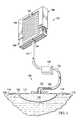
- FIG. 1is a schematic presentation of an illustrative embodiment of a manually-actuated, reduced-pressure system for treating a wound with a portion shown in cross-section and a portion shown in a perspective view;
- FIG. 2is a schematic, exploded perspective view of an illustrative embodiment of a manually-actuated, reduced-pressure apparatus for use with a reduced-pressure system;
- FIGS. 3A and 3Bare schematic cross-sections of a portion of the apparatus of FIG. 2 ;
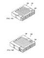
- FIGS. 4A, 4B, and 4Cpresent an illustrative embodiment of a manually-actuated, reduced-pressure apparatus shown in a compressed position, an intermediate position, and an expanded position, respectively;
- FIG. 5is a schematic perspective view of another illustrative embodiment of a manually-actuated, reduced-pressure apparatus.
- FIG. 6is a schematic perspective view of another illustrative embodiment of a manually-actuated, reduced-pressure apparatus.
- tissue site 102may be the bodily tissue of any human, animal, or other organism, including bone tissue, adipose tissue, muscle tissue, dermal tissue, vascular tissue, connective tissue, cartilage, tendons, ligaments, or any other tissue.
- the reduced pressuremay be applied to the tissue site 102 to help promote removal of exudates or other fluids from the tissue site or to stimulate the growth of additional tissue. Unless otherwise indicated, as used herein, “or” does not require mutual exclusivity. In the case of a wound at the tissue site 102 , the growth of granulation tissue and removal of exudates and bacteria helps to promote healing of the wound. In the situation of a non-wounded or non-defective tissue, reduced pressure may be used to promote the growth of tissue that may be harvested and transplanted to another tissue site. As used herein, “reduced pressure” generally refers to a pressure less than the ambient pressure at a tissue site that is being subjected to treatment.
- this reduced pressurewill be less than the atmospheric pressure at which the patient is located.
- the reduced pressuremay be less than a hydrostatic pressure at the tissue site 102 .
- values of pressure stated hereinare gauge pressures.
- vacuum and negative pressuremay be used to describe the pressure applied to the tissue site, the actual pressure applied to the tissue site may be more than the pressure normally associated with a complete vacuum. Consistent with the use herein, an increase in reduced pressure or vacuum pressure typically refers to a relative reduction in absolute pressure.
- the manually-actuated, reduced-pressure system 100includes a manifold member 110 , a sealing member 114 , a reduced-pressure interface 120 , and a reduced-pressure source 140 , which is a manually-actuated, reduced-pressure apparatus.
- a reduced-pressure delivery member 122fluidly couples the reduced-pressure source 140 to the reduced-pressure interface 120 .
- the manifold member 110is placed at the tissue site 102 .
- the manifold member 110may be a biocompatible material that is capable of being placed in contact with the tissue site and distributing reduced pressure to the tissue site.
- the term “manifold” as used hereingenerally refers to a substance or structure that is provided to assist in applying reduced pressure to, delivering fluids to, or removing fluids from a tissue site.
- the manifold member 110typically includes a plurality of flow channels or pathways that distribute fluids provided to and removed from the area of tissue around the manifold. The flow channels may be interconnected.
- manifoldsmay include, without limitation, devices that have structural elements arranged to form flow channels, cellular foam (such as open-cell foam), porous tissue collections, and liquids, gels and foams that include or cure to include flow channels.
- the manifold member 110may be porous and may be made from foam, gauze, felted mat, or any other material suited to a particular biological application.
- the manifold member 110is a porous foam and includes a plurality of interconnected cells or pores that act as flow channels.
- the porous foammay be a polyurethane, open-cell, reticulated foam, such as the GranuFoam® material manufactured by Kinetic Concepts, Incorporated of San Antonio, Tex. Other embodiments might include “closed cells.”
- the manifoldmay also be used to distribute fluids, such as medications, antibacterials, growth factors, and other solutions to the wound.
- Other layersmay be included, such as absorptive materials, wicking materials, hydrophobic materials and hydrophilic materials.
- the sealing member 114is placed over the manifold member 110 and provides a fluid seal adequate for the manually-actuated, reduced-pressure system 100 to hold a reduced pressure at the tissue site 102 .
- Fluid sealor “seal,” means a seal adequate to hold reduced pressure at a desired site given the particular reduced-pressure subsystem or source involved.
- the sealing member 114may be a cover that is used to secure the manifold member 110 at the tissue site 102 . While the sealing member 114 may be impermeable or semi-permeable, the sealing member is capable of maintaining a reduced pressure at the tissue site 102 after installation of the sealing member 114 over the manifold member 110 and a portion of the patient's epidermis.
- the sealing member 114may be a flexible over-drape or film formed from a silicone based compound, acrylic, polyurethane, hydrogel or hydrogel-forming material, or any other biocompatible material that includes the impermeability or permeability characteristics desired for the tissue site 102 .
- the sealing member 114may further include an attachment device 116 to secure the sealing member 114 to a patient's skin.
- the attachment device 116may take many forms.
- an adhesive layer 118may be positioned along a perimeter of the sealing member or any portion of the sealing member to provide the fluid seal.
- the adhesive layer 118may also be pre-applied and covered with a release member that is removed at the time of application.
- the reduced-pressure interface 120permits the passage of fluid from the manifold member 110 to the reduced-pressure delivery member 122 and vice versa.
- exudates collected from tissue site using the manifold member 110may enter the reduced-pressure delivery member 122 via the reduced-pressure interface 120 .
- the system 100may not include the reduced-pressure interface 120 and the reduced-pressure delivery member 122 may be inserted directly through the sealing member 114 and into the manifold member 110 .
- the reduced-pressure delivery member 122may be a medical conduit or tubing or any other device for enabling transportation or transmission of reduced pressure.
- Reduced pressureis generated and supplied to the reduced-pressure delivery member 122 by the reduced-pressure source 140 , which is a manually-actuated, reduced-pressure apparatus.
- the reduced-pressure source 140may include a flexible, collapsible member 146 that is associated with a carrier member 156 and a slider member 168 .
- “associated”means to bring together or into relationship in any of various ways, such as permanently coupling one to another, releasably coupling one to another, aligning members to allow one member to push or pull another member, etc.
- the reduced-pressure source 140includes a constant-force biasing member that urges slider member 168 away from carrier member 156 .
- the reduced-pressure source 140has an evacuation port 153 that allows the air or other fluid in the flexible, collapsible member 146 to exit, but not enter the evacuation port 153 .
- Reduced pressureis delivered by the reduced-pressure source 140 through a reduced-pressure port 154 , which is coupled to the reduced-pressure delivery member 122 and may be operable to allow flow in only one direction—from the reduced-pressure delivery member 122 into the flexible, collapsible member 146 .
- the reduced-pressure source 140is operable to develop a constant reduced pressure.
- constantmeans that a particular reduced pressure may be maintained at the reduced-pressure port 154 at a given level plus or minus five percent.
- the strength of the constant-force biasing memberis a variable for establishing the reduced pressure level produced by the reduced-pressure source 140 .
- a number of different devicesmay be added to a medial portion 124 of the reduced-pressure delivery member 122 .
- a fluid collection member 126may be added to hold exudates and other fluids removed (the fluids may also be held within the flexible, collapsible member 146 ).
- Other examples of devices that may be included on the medial portion 124 of the reduced-pressure delivery member 122include a pressure feedback device, volume detection system, blood detection system, infection detection system, flow monitoring system, temperature monitoring system, etc. Some of these devices, e.g., the fluid collection member, may be formed integrally with the reduced-pressure source 140 .
- the reduced-pressure port 154may include a filter member that includes one or more filters and may include a hydrophobic filter that prevents liquid from entering an interior space within the collapsible member 146 . An odor filter may also be included.
- the manifold member 110is deployed proximate the tissue site 102 , and the sealing member 114 is deployed to create a fluid seal over the manifold member 110 and a portion of the patient's epidermis.
- the reduced-pressure interface 120is coupled to the sealing member 114 .
- the reduced-pressure delivery member 122is coupled between the reduced-pressure interface 120 and the reduced-pressure source 140 .
- the slider member 168is manually actuated or moved toward the carrier member 156 thereby collapsing the flexible, collapsible member 146 and placing the reduced-pressure source 140 in a compressed position. During this movement, air or other fluid in the interior space of the flexible, collapsible member 146 is forced out through the outlet evacuation port 153 .
- the biasingcauses the flexible, collapsible member 146 to want to expand which generates a reduced pressure that is communicated through the reduced-pressure port 154 to the reduced-pressure delivery member 122 and on through the reduced-pressure interface 120 to the manifold member 110 and to the tissue site 102 .
- the flexible, collapsible member 146expands and eventually fills to arrive at an expanded position.
- the flexible, collapsible member 146may be re-primed by placing the flexible, collapsible member 146 in the compressed position again and starting another cycle. An alarm may be added to audibly signal when the expanded position has been reached.
- the manually-actuated, reduced-pressure source 240includes a flexible, collapsible member 246 disposed between a carrier member 256 and a slider member 268 .
- the carrier member 256 and the slider member 268are urged away from each other by a constant-force biasing member 278 .
- the flexible, collapsible member 246has a first end 248 and a second end 250 .
- the flexible, collapsible member 246may hold air or other fluid in an interior portion.
- An evacuation port 253may be located near the first end 248 to allow the air or other fluid to exit the interior space of the flexible, collapsible member 246 .
- a reduced-pressure port 254may be located near the second end 250 .
- the reduced-pressure port 254is fluidly coupled to a reduced-pressure delivery conduit, e.g., reduced-pressure delivery member 122 of FIG. 1 , to provide reduced pressure to a system for treating tissue at a wound site.
- These ports 253 , 254may be located anywhere on the flexible, collapsible member 246 .
- a nodule 255is coupled to the flexible, collapsible member 246 near the second end 250 .
- the nodule 255is added for safety reasons.
- the flexible, collapsible member 246can only be mated with the carrier member 256 and the slider member 268 in one direction.
- the flexible, collapsible member 246may only be installed in the correct way.
- the flexible, collapsible member 246may be formed as bellows.
- the flexible, collapsible member 246is formed with corrugated side walls 245 with corrugations that may move toward and away from one another, resulting in a compression and expansion of compressible bellows.
- the flexible, collapsible member 246may be made from any material, e.g., a flexible polymer, which allows for the compression and expansion of the bellows.
- the shapemay be rectangular, circular, or any other shape.
- the flexible, collapsible member 246may be coupled to the carrier member 256 and slider member 268 by being welded, screwed, glued, bolted, air-lock sealed, snapped or by any other means.
- the term “coupled”generally includes coupling via a separate object and includes direct coupling.
- the term “coupled”also encompasses two or more components that are continuous with one another by virtue of each of the components being formed from the same piece of material.
- the term “coupled”may include chemical, such as via a chemical bond, mechanical, thermal, or electrical coupling.
- the area of an end wall 251 of the flexible, collapsible member 246experiences pressure and transmits a force to the slider member 268 .
- the forceis proportional to the area (F ⁇ PA).
- the reduced pressure generatedcan be controlled by selecting the force of the constant-force biasing member 278 and controlling the area of the end wall 251 .
- the pressure developed by the manually-actuated, reduced-pressure source 240is generally inversely proportional to the area on the interior portion of the end wall 251 of the flexible, collapsible member 246 that faces a slider lateral slider member 276 (P ⁇ F/A).
- the carrier member 256is shown in this illustrative embodiment as having a first socket member 258 and a second socket member 260 .
- the socket members 258 and 260are sized to receive a first constant-force coil spring 280 and a second constant-force coil spring 282 , respectively, and a first arm 270 and a second arm 272 of the slider member 268 , respectively.
- the first socket member 258 and second socket member 260are coupled by a lateral carrier member 262 .
- the lateral carrier member 262is formed with a port channel 264 .
- the port channel 264is sized and configured to securely receive, such as by an interference fit, the evacuation port 253 .
- the socket members 258 and 260may be formed with an indicator window 266 through which a scale, markings, or other visual indicia 274 on an exterior surface 273 of the slider member 268 may be viewed.
- the carrier member 256may be formed as a plurality of components that are coupled through welding, adhesives, bolting, snap fitting, screws, or by any other coupling or may be formed as an integral unit such as by casting.
- the two coil springs 280 , 282could be placed in a single socket member; in that case, it may be desirable to place the indicator window on the opposite side from the side with springs.
- the slider member 268is formed with a first arm 270 and a second arm 272 and has a lateral slider member 276 coupled between the arms 270 , 272 .
- the lateral slider member 276has a first port channel 275 and a second port channel 277 that are sized and configured to securely receive, e.g. with an interference fit, the reduced-pressure port 254 and the nodule 255 (or simulated port), respectively.
- the visual indicia 274such as a scale, may be placed on the exterior surface 273 of one of the arms, e.g., second arm 272 .
- the constant-force biasing member 278includes the first constant-force coil spring 280 and the second constant-force coil spring 282 .
- the first constant-force coil spring 280has a fixation portion 284 and a coil portion 286 .
- the fixation portion 284is coupled proximate to a socket opening 259 of the first socket member 258 and the socket opening 259 is sized to receive the coil portion 286 of the first constant-force coil spring 280 .
- the first arm 270 of the slider member 268is formed with an interface area 271 , or member, that may be concave as shown, and is made to contact the coil portion 286 and to unroll the coil portion 286 or deflect the coil portion 286 as the slider member 268 is manually actuated towards the carrier member 256 .
- FIGS. 3A and 3Ba schematic cross-section of the first socket member 258 , first constant-force coil spring 280 , and first arm 270 are shown initially in an extended position in FIG. 3A , and then in a compressed position in FIG. 3B . Beginning in the extended position of FIG. 3A , the coil portion 286 is near its natural free position, or length.
- the fixation portion 284 of the first constant-force coil spring 280is coupled using a coupling device 283 , such as a spring retainer or a pin, etc.
- the interface area 271presses against the coil portion 286 of the first constant-force coil spring 280 and causes the coil portion 286 to unroll at least partially and all the while the first constant-force coil spring 280 provides a constant force that resists the load being placed on the first constant-force coil spring 280 .
- the first constant-force coil spring 280will continue to urge the first arm 270 away from and out of the first socket member 258 .
- the second constant-force coil spring 282interacts with the second socket member 260 and the second arm 272 in a manner analogous to that shown in FIGS. 3A and 3B for the first constant-force coil spring 280 .
- the manually-actuated, reduced-pressure source 240In operation, the manually-actuated, reduced-pressure source 240 generates a reduced pressure as the manually-actuated, reduced-pressure source 240 moves from a compressed position as shown in FIG. 4A to an intermediate position shown in FIG. 4B and ending in an extended position shown in FIG. 4C .
- the flexible, collapsible member 246is placed with the evacuation port 253 in the port channel 264 of the carrier member 256 and the reduced-pressure port 254 and the nodule 255 are placed in the first port channel 275 and the second port channel 277 , respectively.
- a reduced-pressure delivery conduitmay be connected to the reduced-pressure port 254 .
- the slider member 268is urged towards the carrier member 256 by manually pressing, or activating, the members together such as, for example, with one's hand.
- the constant-force coil springs 280 and 282unwind and the manually-actuated, reduced-pressure source 240 arrives at the compressed position (see FIGS. 3B and 4A ).
- the manually-actuated, constant reduced-pressure source 340includes a flexible, collapsible member 346 , a carrier member 356 , and a slider member 368 .
- Retention members 383couple a constant-force biasing member (not shown) within a portion of the carrier member 356 .
- the constant-force biasing memberprovides a force that urges the slider member 368 away from the carrier member 356 as the manually-actuated, constant reduced-pressure source 340 moves from a compressed position to an extended position.
- the carrier member 356includes a first socket member 358 , a second socket member 360 , and a carrier lateral member 362 .
- the carrier member 356may be formed by component parts that are coupled or may be formed as an integral unit by such means as casting.
- An indicator 365may be included as a part of the manually-actuated, constant reduced-pressure source 340 to indicate remaining capacity or movement.
- the indicator 365may be an indicator window 366 formed on the first socket member 358 or the second socket member 360 that allows for visual indicia that is attached to a portion of the slider member 368 to be seen and thereby provides an indication of how much further the manually-actuated, constant reduced-pressure source 340 can move before reaching its fully-extended position.
- a port channel 364may be formed on the carrier lateral member 362 to help hold a port, such as a reduced-pressure port through which the reduced pressure that is generated within the flexible, collapsible member 346 may be delivered to a reduced-pressure delivery conduit 322 , which transmits the reduced pressure on to a system for treating tissue at a wound site.
- a portsuch as a reduced-pressure port through which the reduced pressure that is generated within the flexible, collapsible member 346 may be delivered to a reduced-pressure delivery conduit 322 , which transmits the reduced pressure on to a system for treating tissue at a wound site.
- the slider member 368has a first arm 370 and a second arm 372 .
- the arms 370 , 372are connected by a slider lateral member 376 .
- the slider lateral member 376may be snapped into position on the two arms 370 , 372 .
- the arms 370 , 372may push a constant-force biasing member located within the socket members 358 and 360 .
- the flexible, collapsible member 346has a first end 348 and a second end 350 .
- a portion of the second end 350may be formed intentionally to hold fluids, such as exudate that may gather within the interior space of the flexible, collapsible member 346 .
- An absorption gel or other absorption materialmay be placed within an interior portion of the collapsible member, such as near the second end 350 .
- the first end 348 of the flexible, collapsible member 346in this particular illustrative embodiment, includes a reduced-pressure port that fits within the port channel 364 on the carrier member 356 .
- the fite.g., an interference fit, may be tight enough to help hold the first end 348 securely to the carrier member 356 or other means of coupling the first end 348 may be utilized such as fasteners, welding, adhesives, etc.
- the second end 350 of flexible, collapsible member 346is formed with a channel or groove or carrier lug 352 that is sized and configured to receive the slider lateral member 376 and to hold the slider lateral member 376 and thereby secure the second end 350 to the slider member 368 .
- the manually-actuated, reduced-pressure apparatus 440includes a flexible, collapsible member 446 , a carrier member 456 , which includes a housing portion 457 , or casing, and a base member 461 .
- the manually-actuated, reduced-pressure apparatus 440further includes a slider member 468 and a constant-force biasing member 478 .
- the flexible, collapsible member 446has a first end 448 and a second end 450 .
- the first end 448is coupled inside of a slider member 468 and the second end 450 is coupled to a base pod 463 of the base member 461 .
- the housing portion 457 , or casing, of the carrier member 456is made to snap into position with the base member 461 to form an integral unit, and this can be done with both a lip portion 490 and with detents, or detent arms 467 , that engage the housing portion 457 .
- the detent arms 467may be used to engage and hold a portion of housing portion 457 and a lip portion 490 may be included to receive and hold the housing portion 457 proximate opening 492 .
- the housing portion 457may include a slider opening 465 in which the slider member 468 may be slidably coupled and may be manually depressed within the slider opening 465 .
- the base member 461may include a reduced-pressure port (not shown) analogous to reduced-pressure port 254 of FIG. 2 for allowing a delivery conduit to be attached and to receive and transmit reduced pressure.
- the reduced-pressure port 254is fluidly coupled to an interior space of the flexible, collapsible member 446 .
- the reduced-pressure port 254may include a counter-bore into the flexible, collapsible member 446 and preferably into a portion of flexible, collapsible member 446 for holding any fluids that might enter.
- the portmay further include a filter carrier with a filter member; the filter member may include a charcoal pellet filter and a sintered hydrophobic filter.
- the slider member 468is formed with an opening 469 .
- the slider member 468is sized to be operable to slide within a portion of the housing portion 457 .
- the constant-force biasing member 478may be a constant-force, coil spring 480 with a fixation portion 484 and a coil portion 486 .
- the center opening of the coil portion 486may be placed upon a drum or pin 488 located on the housing portion 457 .
- the fixation portion 484may be secured near the slider opening 469 .
- the flexible, collapsible member 446is coupled to the base pod 463 where the flexible collapsible member will be held secure and where the flexible, collapsible member 446 is placed into fluid contact with a reduced-pressure port.
- the first end 448 of the flexible, collapsible member 446is placed within opening 469 of the slider member 468 and coupled to a portion of the slider member 468 .
- the housing portion 457is placed over the slider member 468 and the flexible, collapsible member 446 is depressed until the detent arms 467 engage a corresponding receptacle within the opening 492 of the housing portion 457 and the lip 490 engages the opening 492 .
- the constant-force biasing member 478for example, the constant-force, coil spring 480 , is coupled to apparatus 440 by placing the center opening of the coil portion 486 onto the drum 488 of the carrier member 456 and coupling the fixation portion 484 near the opening 469 of the slider member 468 .
- a reduced-pressure delivery conduitis attached to a reduced-pressure port on the base member 461 and then slider member 468 may be depressed, or manually-actuated, by pushing the slider member 468 down further into slider opening 465 to cause manually-actuated, reduced-pressure apparatus 440 to assume a compressed position in which the flexible, collapsible member 446 is collapsed.
- the air or other fluid within the manually-actuated, reduced-pressure apparatus 440is forced out of an evacuation port, which also may be on the bottom side of the base member 461 (analogous to evacuation port 253 of FIG. 2 ).
- a reduced pressureis developed within the interior space of the flexible, collapsible member 446 .
- This reduced pressureis communicated to the reduced-pressure port.
- the constant reduced pressureis thus supplied until the flexible, collapsible member 446 is full of air or other fluid and fluids or until the resting place or free length of the constant-force, coil spring 480 is reached.
- the apparatusprovides a constant reduced pressure with only small variation. Over a period of time the manually-actuated, reduced-pressure apparatus 440 is able to compensate for the ingress by gas or liquid within the flexible, collapsible member 446 .
- the magnitude of the reduced pressuremay be designed and controlled by varying an area of the end of the flexible, collapsible member 446 as well as the spring force of the constant-force, coil spring 480 .
Landscapes
- Health & Medical Sciences (AREA)
- Heart & Thoracic Surgery (AREA)
- Animal Behavior & Ethology (AREA)
- General Health & Medical Sciences (AREA)
- Biomedical Technology (AREA)
- Engineering & Computer Science (AREA)
- Veterinary Medicine (AREA)
- Life Sciences & Earth Sciences (AREA)
- Public Health (AREA)
- Hematology (AREA)
- Anesthesiology (AREA)
- Vascular Medicine (AREA)
- Otolaryngology (AREA)
- External Artificial Organs (AREA)
- Surgical Instruments (AREA)
- Media Introduction/Drainage Providing Device (AREA)
Abstract
Description
Claims (28)
Priority Applications (3)
| Application Number | Priority Date | Filing Date | Title |
|---|---|---|---|
| US14/145,723US9795722B2 (en) | 2008-07-11 | 2013-12-31 | Manually-actuated, reduced-pressure systems for treating wounds |
| US15/711,832US10420866B2 (en) | 2008-07-11 | 2017-09-21 | Manually-actuated, reduced-pressure systems for treating wounds |
| US16/540,522US20190365963A1 (en) | 2008-07-11 | 2019-08-14 | Manually-actuated, reduced-pressure systems for treating wounds |
Applications Claiming Priority (3)
| Application Number | Priority Date | Filing Date | Title |
|---|---|---|---|
| US7986608P | 2008-07-11 | 2008-07-11 | |
| US12/500,134US8641692B2 (en) | 2008-07-11 | 2009-07-09 | Manually-actuated, reduced-pressure systems for treating wounds |
| US14/145,723US9795722B2 (en) | 2008-07-11 | 2013-12-31 | Manually-actuated, reduced-pressure systems for treating wounds |
Related Parent Applications (1)
| Application Number | Title | Priority Date | Filing Date |
|---|---|---|---|
| US12/500,134DivisionUS8641692B2 (en) | 2008-07-11 | 2009-07-09 | Manually-actuated, reduced-pressure systems for treating wounds |
Related Child Applications (1)
| Application Number | Title | Priority Date | Filing Date |
|---|---|---|---|
| US15/711,832ContinuationUS10420866B2 (en) | 2008-07-11 | 2017-09-21 | Manually-actuated, reduced-pressure systems for treating wounds |
Publications (2)
| Publication Number | Publication Date |
|---|---|
| US20140121614A1 US20140121614A1 (en) | 2014-05-01 |
| US9795722B2true US9795722B2 (en) | 2017-10-24 |
Family
ID=41507739
Family Applications (4)
| Application Number | Title | Priority Date | Filing Date |
|---|---|---|---|
| US12/500,134Active2032-01-29US8641692B2 (en) | 2008-07-11 | 2009-07-09 | Manually-actuated, reduced-pressure systems for treating wounds |
| US14/145,723Active2031-01-04US9795722B2 (en) | 2008-07-11 | 2013-12-31 | Manually-actuated, reduced-pressure systems for treating wounds |
| US15/711,832ActiveUS10420866B2 (en) | 2008-07-11 | 2017-09-21 | Manually-actuated, reduced-pressure systems for treating wounds |
| US16/540,522AbandonedUS20190365963A1 (en) | 2008-07-11 | 2019-08-14 | Manually-actuated, reduced-pressure systems for treating wounds |
Family Applications Before (1)
| Application Number | Title | Priority Date | Filing Date |
|---|---|---|---|
| US12/500,134Active2032-01-29US8641692B2 (en) | 2008-07-11 | 2009-07-09 | Manually-actuated, reduced-pressure systems for treating wounds |
Family Applications After (2)
| Application Number | Title | Priority Date | Filing Date |
|---|---|---|---|
| US15/711,832ActiveUS10420866B2 (en) | 2008-07-11 | 2017-09-21 | Manually-actuated, reduced-pressure systems for treating wounds |
| US16/540,522AbandonedUS20190365963A1 (en) | 2008-07-11 | 2019-08-14 | Manually-actuated, reduced-pressure systems for treating wounds |
Country Status (12)
| Country | Link |
|---|---|
| US (4) | US8641692B2 (en) |
| EP (3) | EP2977068B1 (en) |
| JP (2) | JP6005358B2 (en) |
| KR (1) | KR20110033264A (en) |
| CN (2) | CN104147648B (en) |
| AU (1) | AU2009268518B2 (en) |
| BR (1) | BRPI0910354A2 (en) |
| CA (2) | CA2730086C (en) |
| MX (1) | MX2011000286A (en) |
| RU (1) | RU2011101663A (en) |
| TW (1) | TW201008603A (en) |
| WO (1) | WO2010006182A2 (en) |
Cited By (3)
| Publication number | Priority date | Publication date | Assignee | Title |
|---|---|---|---|---|
| WO2020043817A1 (en)* | 2018-08-30 | 2020-03-05 | Egon Wiest | Drainage device and drainage set |
| US11219712B2 (en)* | 2013-03-13 | 2022-01-11 | Kci Licensing, Inc. | Collapsible canister for use with reduced pressure therapy device |
| US20240082477A1 (en)* | 2011-06-24 | 2024-03-14 | 3M Innovative Properties Company | Reduced-pressure dressings employing tissue-fixation elements |
Families Citing this family (50)
| Publication number | Priority date | Publication date | Assignee | Title |
|---|---|---|---|---|
| US11298453B2 (en) | 2003-10-28 | 2022-04-12 | Smith & Nephew Plc | Apparatus and method for wound cleansing with actives |
| GB0508531D0 (en) | 2005-04-27 | 2005-06-01 | Smith & Nephew | Sai with ultrasound |
| EP2129409B2 (en) | 2007-03-14 | 2021-11-24 | The Board of Trustees of the Leland Stanford Junior University | Devices for application of reduced pressure therapy |
| EP2203137B1 (en) | 2007-10-11 | 2016-02-24 | Spiracur, Inc. | Closed incision negative pressure wound therapy device |
| WO2009067711A2 (en) | 2007-11-21 | 2009-05-28 | T.J. Smith & Nephew, Limited | Suction device and dressing |
| AU2009214439B2 (en) | 2008-02-14 | 2014-09-25 | Solventum Intellectual Properties Company | Devices and methods for treatment of damaged tissue |
| CA2744548C (en) | 2008-11-25 | 2017-06-13 | Spiracur Inc. | Device for delivery of reduced pressure to body surfaces |
| US8361043B2 (en)* | 2009-01-07 | 2013-01-29 | Spiracur Inc. | Reduced pressure therapy of the sacral region |
| US8728045B2 (en)* | 2009-03-04 | 2014-05-20 | Spiracur Inc. | Devices and methods to apply alternating level of reduced pressure to tissue |
| US8444614B2 (en) | 2009-04-10 | 2013-05-21 | Spiracur, Inc. | Methods and devices for applying closed incision negative pressure wound therapy |
| US10792404B2 (en) | 2009-04-10 | 2020-10-06 | Kci Licensing, Inc. | Methods and devices for applying closed incision negative pressure wound therapy |
| ITMI20100237A1 (en)* | 2010-02-17 | 2011-08-18 | Eurosets Srl | MANUAL BELLOWS PUMP FOR THE CREATION OF VACUUM IN A RIGID CONTAINER, PARTICULARLY FOR MEDICAL USE. |
| GB201011173D0 (en) | 2010-07-02 | 2010-08-18 | Smith & Nephew | Provision of wound filler |
| US11291760B2 (en) | 2010-08-10 | 2022-04-05 | Kci Licensing, Inc. | Controlled negative pressure apparatus and alarm mechanism |
| US8753322B2 (en) | 2010-08-10 | 2014-06-17 | Spiracur Inc. | Controlled negative pressure apparatus and alarm mechanism |
| US8795246B2 (en) | 2010-08-10 | 2014-08-05 | Spiracur Inc. | Alarm system |
| CA2819032C (en) | 2010-11-25 | 2020-06-23 | Smith & Nephew Plc | Composition i-ii and products and uses thereof |
| GB201020005D0 (en) | 2010-11-25 | 2011-01-12 | Smith & Nephew | Composition 1-1 |
| WO2012078724A1 (en)* | 2010-12-08 | 2012-06-14 | Convatec Technologies Inc. | Apparatus and method for applying pressure to a wound site |
| EP2548589B1 (en)* | 2011-07-18 | 2014-08-06 | Laboratoires Urgo | Negative pressure wound treatment assembly |
| US20150159066A1 (en) | 2011-11-25 | 2015-06-11 | Smith & Nephew Plc | Composition, apparatus, kit and method and uses thereof |
| JP6370783B2 (en)* | 2012-07-30 | 2018-08-08 | ケーシーアイ ライセンシング インコーポレイテッド | Absorbable vacuum dressing and system for treating tissue sites |
| US20160120706A1 (en) | 2013-03-15 | 2016-05-05 | Smith & Nephew Plc | Wound dressing sealant and use thereof |
| US10758648B2 (en) | 2013-03-15 | 2020-09-01 | Kci Licensing, Inc. | Vacuum cartridge with integrated valve |
| EP2968647B1 (en) | 2013-03-15 | 2022-06-29 | Smith & Nephew plc | Wound dressing sealant and use thereof |
| US10010658B2 (en) | 2013-05-10 | 2018-07-03 | Smith & Nephew Plc | Fluidic connector for irrigation and aspiration of wounds |
| ITBO20130350A1 (en)* | 2013-07-05 | 2015-01-06 | Med Europ Europ Medical Supplie S S R L | DEVICE FOR DRAINAGE OF INJURIES AND INJURIES IN GENERAL. |
| US10426876B2 (en) | 2013-10-14 | 2019-10-01 | Vesucta Aps | Brest pump device |
| EP3939554A1 (en) | 2014-02-11 | 2022-01-19 | 3M Innovative Properties Company | Devices for applying closed incision negative pressure wound therapy |
| US9770369B2 (en) | 2014-08-08 | 2017-09-26 | Neogenix, Llc | Wound care devices, apparatus, and treatment methods |
| US11065019B1 (en) | 2015-02-04 | 2021-07-20 | Route 92 Medical, Inc. | Aspiration catheter systems and methods of use |
| JP2018519884A (en)* | 2015-05-26 | 2018-07-26 | スミス アンド ネフュー ピーエルシーSmith & Nephew Public Limited Company | Compressible negative pressure source and method of use |
| EP3714916A1 (en) | 2015-07-29 | 2020-09-30 | Innovative Therapies Inc. | Wound therapy device pressure monitoring and control system |
| US11027050B2 (en)* | 2015-09-01 | 2021-06-08 | Kci Licensing, Inc. | Reduced pressure tissue therapy device |
| CN105457109A (en)* | 2015-12-28 | 2016-04-06 | 昆山韦睿医疗科技有限公司 | Manual negative pressure treatment device |
| WO2017139394A1 (en)* | 2016-02-09 | 2017-08-17 | Kci Licensing, Inc. | A negative-pressure therapy apparatus with push-to-release actuator |
| CN115054413A (en) | 2016-09-29 | 2022-09-16 | 美国医疗设备有限公司 | Method of adjusting effective length of stent and prosthesis delivery catheter assembly |
| EP4467111A3 (en) | 2017-03-15 | 2025-03-05 | Merit Medical Systems, Inc. | Transluminal stents |
| US10687676B2 (en)* | 2017-06-09 | 2020-06-23 | Hamilton Sundstrand Corporation | Microgravity urine collection and storage |
| CN107551331B (en)* | 2017-09-14 | 2024-05-10 | 中国人民解放军第二军医大学 | Pressure limiting device for negative pressure drainage device for pleuroperitoneal cavity |
| US20210001020A1 (en)* | 2018-03-30 | 2021-01-07 | Kci Licensing, Inc. | Manual Pump With Charge Capability |
| CN112165961A (en) | 2018-04-02 | 2021-01-01 | Ic外科公司 | Negative pressure pump and related methods |
| CN108671284A (en)* | 2018-06-07 | 2018-10-19 | 张文静 | A kind of negative pressure therapeutic devices for the thin-skinned tissue defect disease of cranium jaw |
| US11712258B2 (en)* | 2018-12-10 | 2023-08-01 | Covidien Lp | Tissue resection systems including fluid outflow management |
| US11452806B2 (en)* | 2019-10-04 | 2022-09-27 | Covidien Lp | Outflow collection vessels, systems, and components thereof for hysteroscopic surgical procedures |
| IT202000019474A1 (en)* | 2020-08-06 | 2022-02-06 | Medicud S R L | NEGATIVE PRESSURE MEDICAL DEVICE |
| US12208197B2 (en)* | 2020-12-11 | 2025-01-28 | Hisham Alshaer | Manually operated negative pressure wound treatment apparatus coupled with smart feedback system |
| CN117693370A (en)* | 2021-06-22 | 2024-03-12 | 巴德外周血管股份有限公司 | Drainage system comprising a fluid collection device with selectable negative pressure for draining and collecting body fluids from a body cavity |
| EP4561651A1 (en)* | 2022-07-29 | 2025-06-04 | Bard Peripheral Vascular, Inc. | Drainage systems including bellows-type pump for providing a negative pressure for draining and collecting bodily fluids |
| CN117679568B (en)* | 2024-02-02 | 2024-04-09 | 佳木斯大学 | External positioner and positioning bracket for medical surgical drainage tube |
Citations (129)
| Publication number | Priority date | Publication date | Assignee | Title |
|---|---|---|---|---|
| US1355846A (en) | 1920-02-06 | 1920-10-19 | David A Rannells | Medical appliance |
| US2547758A (en) | 1949-01-05 | 1951-04-03 | Wilmer B Keeling | Instrument for treating the male urethra |
| US2632443A (en) | 1949-04-18 | 1953-03-24 | Eleanor P Lesher | Surgical dressing |
| GB692578A (en) | 1949-09-13 | 1953-06-10 | Minnesota Mining & Mfg | Improvements in or relating to drape sheets for surgical use |
| US2682873A (en) | 1952-07-30 | 1954-07-06 | Johnson & Johnson | General purpose protective dressing |
| US2910763A (en) | 1955-08-17 | 1959-11-03 | Du Pont | Felt-like products |
| US2969057A (en) | 1957-11-04 | 1961-01-24 | Brady Co W H | Nematodic swab |
| US3066672A (en) | 1960-09-27 | 1962-12-04 | Jr William H Crosby | Method and apparatus for serial sampling of intestinal juice |
| US3367332A (en) | 1965-08-27 | 1968-02-06 | Gen Electric | Product and process for establishing a sterile area of skin |
| US3520300A (en) | 1967-03-15 | 1970-07-14 | Amp Inc | Surgical sponge and suction device |
| US3568675A (en) | 1968-08-30 | 1971-03-09 | Clyde B Harvey | Fistula and penetrating wound dressing |
| US3648692A (en) | 1970-12-07 | 1972-03-14 | Parke Davis & Co | Medical-surgical dressing for burns and the like |
| US3682180A (en) | 1970-06-08 | 1972-08-08 | Coilform Co Inc | Drain clip for surgical drain |
| US3809087A (en) | 1973-05-17 | 1974-05-07 | R Lewis | Closed wound suction apparatus having biased plate members |
| US3826254A (en) | 1973-02-26 | 1974-07-30 | Verco Ind | Needle or catheter retaining appliance |
| DE2640413A1 (en) | 1976-09-08 | 1978-03-09 | Wolf Gmbh Richard | CATHETER MONITORING DEVICE |
| US4080970A (en) | 1976-11-17 | 1978-03-28 | Miller Thomas J | Post-operative combination dressing and internal drain tube with external shield and tube connector |
| US4096853A (en) | 1975-06-21 | 1978-06-27 | Hoechst Aktiengesellschaft | Device for the introduction of contrast medium into an anus praeter |
| US4139004A (en) | 1977-02-17 | 1979-02-13 | Gonzalez Jr Harry | Bandage apparatus for treating burns |
| US4165748A (en) | 1977-11-07 | 1979-08-28 | Johnson Melissa C | Catheter tube holder |
| US4184510A (en) | 1977-03-15 | 1980-01-22 | Fibra-Sonics, Inc. | Valued device for controlling vacuum in surgery |
| WO1980002182A1 (en) | 1979-04-06 | 1980-10-16 | J Moss | Portable suction device for collecting fluids from a closed wound |
| US4233969A (en) | 1976-11-11 | 1980-11-18 | Lock Peter M | Wound dressing materials |
| US4245630A (en) | 1976-10-08 | 1981-01-20 | T. J. Smith & Nephew, Ltd. | Tearable composite strip of materials |
| US4256109A (en) | 1978-07-10 | 1981-03-17 | Nichols Robert L | Shut off valve for medical suction apparatus |
| US4261363A (en) | 1979-11-09 | 1981-04-14 | C. R. Bard, Inc. | Retention clips for body fluid drains |
| US4275721A (en) | 1978-11-28 | 1981-06-30 | Landstingens Inkopscentral Lic, Ekonomisk Forening | Vein catheter bandage |
| US4278089A (en) | 1978-11-09 | 1981-07-14 | Howmedica, Inc. | Wound drainage device |
| US4284079A (en) | 1979-06-28 | 1981-08-18 | Adair Edwin Lloyd | Method for applying a male incontinence device |
| US4297995A (en) | 1980-06-03 | 1981-11-03 | Key Pharmaceuticals, Inc. | Bandage containing attachment post |
| US4333468A (en) | 1980-08-18 | 1982-06-08 | Geist Robert W | Mesentery tube holder apparatus |
| US4373519A (en) | 1981-06-26 | 1983-02-15 | Minnesota Mining And Manufacturing Company | Composite wound dressing |
| US4382441A (en) | 1978-12-06 | 1983-05-10 | Svedman Paul | Device for treating tissues, for example skin |
| US4392858A (en) | 1981-07-16 | 1983-07-12 | Sherwood Medical Company | Wound drainage device |
| US4392853A (en) | 1981-03-16 | 1983-07-12 | Rudolph Muto | Sterile assembly for protecting and fastening an indwelling device |
| US4419097A (en) | 1981-07-31 | 1983-12-06 | Rexar Industries, Inc. | Attachment for catheter tube |
| EP0100148A1 (en) | 1982-07-06 | 1984-02-08 | Dow Corning Limited | Medical-surgical dressing and a process for the production thereof |
| US4465485A (en) | 1981-03-06 | 1984-08-14 | Becton, Dickinson And Company | Suction canister with unitary shut-off valve and filter features |
| EP0117632A2 (en) | 1983-01-27 | 1984-09-05 | Johnson & Johnson Products Inc. | Adhesive film dressing |
| US4475909A (en) | 1982-05-06 | 1984-10-09 | Eisenberg Melvin I | Male urinary device and method for applying the device |
| US4480638A (en) | 1980-03-11 | 1984-11-06 | Eduard Schmid | Cushion for holding an element of grafted skin |
| US4525374A (en) | 1984-02-27 | 1985-06-25 | Manresa, Inc. | Treating hydrophobic filters to render them hydrophilic |
| US4525166A (en) | 1981-11-21 | 1985-06-25 | Intermedicat Gmbh | Rolled flexible medical suction drainage device |
| US4540412A (en) | 1983-07-14 | 1985-09-10 | The Kendall Company | Device for moist heat therapy |
| US4543100A (en) | 1983-11-01 | 1985-09-24 | Brodsky Stuart A | Catheter and drain tube retainer |
| US4548202A (en) | 1983-06-20 | 1985-10-22 | Ethicon, Inc. | Mesh tissue fasteners |
| US4551139A (en) | 1982-02-08 | 1985-11-05 | Marion Laboratories, Inc. | Method and apparatus for burn wound treatment |
| EP0161865A2 (en) | 1984-05-03 | 1985-11-21 | Smith and Nephew Associated Companies p.l.c. | Adhesive wound dressing |
| US4569348A (en) | 1980-02-22 | 1986-02-11 | Velcro Usa Inc. | Catheter tube holder strap |
| AU550575B2 (en) | 1981-08-07 | 1986-03-27 | Richard Christian Wright | Wound drainage device |
| US4605399A (en) | 1984-12-04 | 1986-08-12 | Complex, Inc. | Transdermal infusion device |
| US4608041A (en) | 1981-10-14 | 1986-08-26 | Frese Nielsen | Device for treatment of wounds in body tissue of patients by exposure to jets of gas |
| US4640688A (en) | 1985-08-23 | 1987-02-03 | Mentor Corporation | Urine collection catheter |
| US4655754A (en) | 1984-11-09 | 1987-04-07 | Stryker Corporation | Vacuum wound drainage system and lipids baffle therefor |
| US4664662A (en) | 1984-08-02 | 1987-05-12 | Smith And Nephew Associated Companies Plc | Wound dressing |
| WO1987004626A1 (en) | 1986-01-31 | 1987-08-13 | Osmond, Roger, L., W. | Suction system for wound and gastro-intestinal drainage |
| US4710165A (en) | 1985-09-16 | 1987-12-01 | Mcneil Charles B | Wearable, variable rate suction/collection device |
| US4733659A (en) | 1986-01-17 | 1988-03-29 | Seton Company | Foam bandage |
| GB2195255A (en) | 1986-09-30 | 1988-04-07 | Vacutec Uk Limited | Method and apparatus for vacuum treatment of an epidermal surface |
| US4743232A (en) | 1986-10-06 | 1988-05-10 | The Clinipad Corporation | Package assembly for plastic film bandage |
| GB2197789A (en) | 1986-11-28 | 1988-06-02 | Smiths Industries Plc | Anti-foaming disinfectants used in surgical suction apparatus |
| US4758220A (en) | 1985-09-26 | 1988-07-19 | Alcon Laboratories, Inc. | Surgical cassette proximity sensing and latching apparatus |
| US4787888A (en) | 1987-06-01 | 1988-11-29 | University Of Connecticut | Disposable piezoelectric polymer bandage for percutaneous delivery of drugs and method for such percutaneous delivery (a) |
| US4826494A (en) | 1984-11-09 | 1989-05-02 | Stryker Corporation | Vacuum wound drainage system |
| US4838883A (en) | 1986-03-07 | 1989-06-13 | Nissho Corporation | Urine-collecting device |
| US4840187A (en) | 1986-09-11 | 1989-06-20 | Bard Limited | Sheath applicator |
| US4863449A (en) | 1987-07-06 | 1989-09-05 | Hollister Incorporated | Adhesive-lined elastic condom cathether |
| US4872450A (en) | 1984-08-17 | 1989-10-10 | Austad Eric D | Wound dressing and method of forming same |
| US4878901A (en) | 1986-10-10 | 1989-11-07 | Sachse Hans Ernst | Condom catheter, a urethral catheter for the prevention of ascending infections |
| GB2220357A (en) | 1988-05-28 | 1990-01-10 | Smiths Industries Plc | Medico-surgical containers |
| US4897081A (en) | 1984-05-25 | 1990-01-30 | Thermedics Inc. | Percutaneous access device |
| US4906240A (en) | 1988-02-01 | 1990-03-06 | Matrix Medica, Inc. | Adhesive-faced porous absorbent sheet and method of making same |
| US4906233A (en) | 1986-05-29 | 1990-03-06 | Terumo Kabushiki Kaisha | Method of securing a catheter body to a human skin surface |
| US4919654A (en) | 1988-08-03 | 1990-04-24 | Kalt Medical Corporation | IV clamp with membrane |
| CA2005436A1 (en) | 1988-12-13 | 1990-06-13 | Glenda G. Kalt | Transparent tracheostomy tube dressing |
| US4941882A (en) | 1987-03-14 | 1990-07-17 | Smith And Nephew Associated Companies, P.L.C. | Adhesive dressing for retaining a cannula on the skin |
| US4953565A (en) | 1986-11-26 | 1990-09-04 | Shunro Tachibana | Endermic application kits for external medicines |
| WO1990010424A1 (en) | 1989-03-16 | 1990-09-20 | Smith & Nephew Plc | Absorbent devices and precursors therefor |
| US4969880A (en) | 1989-04-03 | 1990-11-13 | Zamierowski David S | Wound dressing and treatment method |
| US4985019A (en) | 1988-03-11 | 1991-01-15 | Michelson Gary K | X-ray marker |
| GB2235877A (en) | 1989-09-18 | 1991-03-20 | Antonio Talluri | Closed wound suction apparatus |
| US5037397A (en) | 1985-05-03 | 1991-08-06 | Medical Distributors, Inc. | Universal clamp |
| US5086170A (en) | 1989-01-16 | 1992-02-04 | Roussel Uclaf | Process for the preparation of azabicyclo compounds |
| US5092858A (en) | 1990-03-20 | 1992-03-03 | Becton, Dickinson And Company | Liquid gelling agent distributor device |
| US5100396A (en) | 1989-04-03 | 1992-03-31 | Zamierowski David S | Fluidic connection system and method |
| JPH04129536A (en) | 1990-09-19 | 1992-04-30 | Terumo Corp | Balance device |
| US5134994A (en) | 1990-02-12 | 1992-08-04 | Say Sam L | Field aspirator in a soft pack with externally mounted container |
| US5149331A (en) | 1991-05-03 | 1992-09-22 | Ariel Ferdman | Method and device for wound closure |
| US5167613A (en) | 1992-03-23 | 1992-12-01 | The Kendall Company | Composite vented wound dressing |
| US5176663A (en) | 1987-12-02 | 1993-01-05 | Pal Svedman | Dressing having pad with compressibility limiting elements |
| WO1993009727A1 (en) | 1991-11-14 | 1993-05-27 | Wake Forest University | Method and apparatus for treating tissue damage |
| US5215522A (en) | 1984-07-23 | 1993-06-01 | Ballard Medical Products | Single use medical aspirating device and method |
| US5232453A (en) | 1989-07-14 | 1993-08-03 | E. R. Squibb & Sons, Inc. | Catheter holder |
| US5261893A (en) | 1989-04-03 | 1993-11-16 | Zamierowski David S | Fastening system and method |
| US5278100A (en) | 1991-11-08 | 1994-01-11 | Micron Technology, Inc. | Chemical vapor deposition technique for depositing titanium silicide on semiconductor wafers |
| US5279550A (en) | 1991-12-19 | 1994-01-18 | Gish Biomedical, Inc. | Orthopedic autotransfusion system |
| US5298015A (en) | 1989-07-11 | 1994-03-29 | Nippon Zeon Co., Ltd. | Wound dressing having a porous structure |
| US5342376A (en) | 1993-05-03 | 1994-08-30 | Dermagraphics, Inc. | Inserting device for a barbed tissue connector |
| US5344415A (en) | 1993-06-15 | 1994-09-06 | Deroyal Industries, Inc. | Sterile system for dressing vascular access site |
| DE4306478A1 (en) | 1993-03-02 | 1994-09-08 | Wolfgang Dr Wagner | Drainage device, in particular pleural drainage device, and drainage method |
| WO1994020041A1 (en) | 1993-03-09 | 1994-09-15 | Wake Forest University | Wound treatment employing reduced pressure |
| US5358494A (en) | 1989-07-11 | 1994-10-25 | Svedman Paul | Irrigation dressing |
| US5437651A (en) | 1993-09-01 | 1995-08-01 | Research Medical, Inc. | Medical suction apparatus |
| US5437622A (en) | 1992-04-29 | 1995-08-01 | Laboratoire Hydrex (Sa) | Transparent adhesive dressing with reinforced starter cuts |
| DE29504378U1 (en) | 1995-03-15 | 1995-09-14 | MTG Medizinisch, technische Gerätebau GmbH, 66299 Friedrichsthal | Electronically controlled low-vacuum pump for chest and wound drainage |
| WO1996005873A1 (en) | 1994-08-22 | 1996-02-29 | Kinetic Concepts Inc. | Wound drainage equipment |
| US5527293A (en) | 1989-04-03 | 1996-06-18 | Kinetic Concepts, Inc. | Fastening system and method |
| US5549584A (en) | 1994-02-14 | 1996-08-27 | The Kendall Company | Apparatus for removing fluid from a wound |
| US5556375A (en) | 1994-06-16 | 1996-09-17 | Hercules Incorporated | Wound dressing having a fenestrated base layer |
| US5607388A (en) | 1994-06-16 | 1997-03-04 | Hercules Incorporated | Multi-purpose wound dressing |
| WO1997018007A1 (en) | 1995-11-14 | 1997-05-22 | Kci Medical Limited | Portable wound treatment apparatus |
| WO1999013793A1 (en) | 1997-09-12 | 1999-03-25 | Kci Medical Limited | Surgical drape and suction head for wound treatment |
| US6071267A (en) | 1998-02-06 | 2000-06-06 | Kinetic Concepts, Inc. | Medical patient fluid management interface system and method |
| US6135116A (en) | 1997-07-28 | 2000-10-24 | Kci Licensing, Inc. | Therapeutic method for treating ulcers |
| US6174306B1 (en) | 1995-05-13 | 2001-01-16 | Wim Fleischmann | Device for vacuum-sealing an injury |
| US6241747B1 (en) | 1993-05-03 | 2001-06-05 | Quill Medical, Inc. | Barbed Bodily tissue connector |
| US6287316B1 (en) | 1999-03-26 | 2001-09-11 | Ethicon, Inc. | Knitted surgical mesh |
| US20020077661A1 (en) | 2000-12-20 | 2002-06-20 | Vahid Saadat | Multi-barbed device for retaining tissue in apposition and methods of use |
| US20020082567A1 (en) | 2000-11-29 | 2002-06-27 | Lockwood Jeffrey S. | Vacuum therapy and cleansing dressing for wounds |
| US20020115951A1 (en) | 2001-02-22 | 2002-08-22 | Core Products International, Inc. | Ankle brace providing upper and lower ankle adjustment |
| US20020120185A1 (en) | 2000-05-26 | 2002-08-29 | Kci Licensing, Inc. | System for combined transcutaneous blood gas monitoring and vacuum assisted wound closure |
| US20020143286A1 (en) | 2001-03-05 | 2002-10-03 | Kci Licensing, Inc. | Vacuum assisted wound treatment apparatus and infection identification system and method |
| US6488643B1 (en) | 1998-10-08 | 2002-12-03 | Kci Licensing, Inc. | Wound healing foot wrap |
| US6493568B1 (en) | 1994-07-19 | 2002-12-10 | Kci Licensing, Inc. | Patient interface system |
| AU755496B2 (en) | 1997-09-12 | 2002-12-12 | Kci Licensing, Inc. | Surgical drape and suction head for wound treatment |
| US20060079852A1 (en) | 2002-12-31 | 2006-04-13 | Bubb Stephen K | Externally-applied patient interface system and method |
| JP4129536B2 (en) | 2000-02-24 | 2008-08-06 | ヴェネテック インターナショナル,インコーポレイテッド | Highly compatible catheter anchoring system |
| US8377079B2 (en)* | 2007-12-27 | 2013-02-19 | Ethicon Endo-Surgery, Inc. | Constant force mechanisms for regulating restriction devices |
| US8961481B2 (en) | 2008-02-14 | 2015-02-24 | Spiracur Inc. | Devices and methods for treatment of damaged tissue |
Family Cites Families (88)
| Publication number | Priority date | Publication date | Assignee | Title |
|---|---|---|---|---|
| US3084691A (en) | 1960-11-04 | 1963-04-09 | Air Shields | Aspirator |
| GB1052614A (en) | 1964-06-04 | |||
| US4141361A (en) | 1970-02-09 | 1979-02-27 | Snyder Manufacturing Co., Incorporated | Evacuator |
| US3742952A (en) | 1971-04-28 | 1973-07-03 | Alpha Ind Inc | Surgical suction pump assembly |
| US3779243A (en) | 1971-10-15 | 1973-12-18 | J Tussey | Contamination free surgical evacuator |
| US3774611A (en) | 1972-06-08 | 1973-11-27 | J Tussey | Stabilized contamination free surgical evacuator |
| FR2206741A5 (en) | 1972-11-14 | 1974-06-07 | Labat Merle Sa | |
| US3875941A (en) | 1974-04-03 | 1975-04-08 | Medical Dynamics Inc | System for evacuating fluids from the body |
| US4098434A (en) | 1975-06-20 | 1978-07-04 | Owens-Illinois, Inc. | Fluid product dispenser |
| DE2608066C2 (en)* | 1976-02-28 | 1982-08-19 | Diehl GmbH & Co, 8500 Nürnberg | Optical distance sensor for projectile detonators |
| US4460354A (en) | 1980-07-08 | 1984-07-17 | Snyder Laboratories, Inc. | Closed wound suction evacuator |
| US4529402A (en) | 1980-07-08 | 1985-07-16 | Snyder Laboratories, Inc. | Closed wound suction evacuator with rotary valve |
| US4404924A (en) | 1980-09-05 | 1983-09-20 | Uresil Company | Body fluid suction device indicators |
| US4429693A (en) | 1980-09-16 | 1984-02-07 | Blake L W | Surgical fluid evacuator |
| US4372297A (en) | 1980-11-28 | 1983-02-08 | The Kendall Company | Compression device |
| DE3218561C2 (en) | 1982-05-17 | 1988-08-18 | Günter H. Dr.-Ing. 8035 Gauting Marx | Device for taking up and reinfusing blood |
| US4578060A (en) | 1983-07-20 | 1986-03-25 | Howmedica, Inc. | Wound drainage device |
| US4643719A (en) | 1984-07-19 | 1987-02-17 | Garth Geoffrey C | Manually operable aspirator |
| US4798583A (en) | 1984-11-16 | 1989-01-17 | Walter Beck | Method and apparatus for aspirating secreted fluids from a wound |
| US4664652A (en) | 1985-02-07 | 1987-05-12 | Snyder Laboratories, Inc. | Wound evacuator |
| DK156028C (en) | 1986-05-16 | 1989-11-06 | Testa Lab A S | ASPIRATOR |
| US5102404A (en) | 1986-12-15 | 1992-04-07 | Uresil Corporation | Apparatus and method for collecting body fluids |
| US5019059A (en) | 1986-12-15 | 1991-05-28 | Uresil Corporation | Apparatus and method for collecting body fluids |
| US4903726A (en) | 1987-08-10 | 1990-02-27 | Aeros Instruments, Inc. | Medical vacuum regulating cartridge |
| US4828546A (en) | 1987-08-21 | 1989-05-09 | Surgidyne, Inc. | Bulb evacuator for closed wound suction |
| US4981474A (en) | 1988-02-16 | 1991-01-01 | Baxter Travenol Laboratories, Inc. | Body fluid drainage device |
| US5718355A (en) | 1989-02-03 | 1998-02-17 | Senetics, Inc. | Indicator device responsive to axial force for use with inhaler |
| US5226877A (en) | 1989-06-23 | 1993-07-13 | Epstein Gordon H | Method and apparatus for preparing fibrinogen adhesive from whole blood |
| US5112323A (en) | 1990-02-08 | 1992-05-12 | Snyder Laboratories, Inc. | Wound evacuator |
| GB2245833A (en) | 1990-06-26 | 1992-01-15 | Femcare Ltd | Mucus extractor |
| US5342329A (en) | 1991-10-11 | 1994-08-30 | Inmed Ltda. | Portable disposable device for post-surgical suction |
| CN2142728Y (en) | 1992-12-16 | 1993-09-29 | 牛志忠 | Medical simple suction-device |
| US5304129A (en) | 1993-07-12 | 1994-04-19 | Forgach Suzanne E | Pivotable foot operated breast pump |
| JP2571666B2 (en) | 1993-10-26 | 1997-01-16 | 大研医器株式会社 | Suction liquid collecting device |
| US5592948A (en) | 1994-01-28 | 1997-01-14 | Gatten; Ronald A. | Self contained vial for drawing, storing, sealing and identifying a fluid sample |
| US5645540A (en) | 1994-10-11 | 1997-07-08 | Stryker Corporation | Blood conservation system |
| US5554011A (en) | 1994-10-27 | 1996-09-10 | Symbiosis Corporation | Medical fluid pump powered by a constant source of vacuum |
| US6261276B1 (en) | 1995-03-13 | 2001-07-17 | I.S.I. International, Inc. | Apparatus for draining surgical wounds |
| DE29506682U1 (en) | 1995-04-19 | 1995-06-29 | Megaplast Dosiersysteme GmbH, 78052 Villingen-Schwenningen | Dispensing pump made of plastic for pasty materials |
| US5714696A (en) | 1995-07-06 | 1998-02-03 | The Regents Of The University Of California | Fluid sampling apparatus and method |
| GB9521397D0 (en) | 1995-10-18 | 1995-12-20 | Summit Medical Ltd | Wound drainage system |
| US5827246A (en) | 1996-02-28 | 1998-10-27 | Tecnol Medical Products, Inc. | Vacuum pad for collecting potentially hazardous fluids |
| NL1006457C2 (en) | 1997-07-03 | 1999-01-05 | Polymedics N V | Drainage system to be used with an open wound, element used for applying a drainage pipe or hose and method for applying the drainage system. |
| US6656149B2 (en) | 2000-04-13 | 2003-12-02 | Leland L. Ladd | Expansible medical suction canister |
| US6764462B2 (en) | 2000-11-29 | 2004-07-20 | Hill-Rom Services Inc. | Wound treatment apparatus |
| GB0011202D0 (en)* | 2000-05-09 | 2000-06-28 | Kci Licensing Inc | Abdominal wound dressing |
| US7070584B2 (en) | 2001-02-20 | 2006-07-04 | Kci Licensing, Inc. | Biocompatible wound dressing |
| DE10124886C2 (en) | 2001-05-22 | 2003-04-30 | Draeger Medical Ag | Anesthetic agent container with dosing elements |
| GB0113750D0 (en) | 2001-06-06 | 2001-07-25 | Rocket Medical Plc | Autologous blood transfusion apparatus |
| US7004915B2 (en) | 2001-08-24 | 2006-02-28 | Kci Licensing, Inc. | Negative pressure assisted tissue treatment system |
| US6648862B2 (en) | 2001-11-20 | 2003-11-18 | Spheric Products, Ltd. | Personally portable vacuum desiccator |
| AU2002359828A1 (en) | 2001-12-26 | 2003-07-24 | Hill-Rom Services Inc. | Vented vacuum bandage and method |
| US8168848B2 (en) | 2002-04-10 | 2012-05-01 | KCI Medical Resources, Inc. | Access openings in vacuum bandage |
| US6485007B1 (en) | 2002-05-07 | 2002-11-26 | Vat Holding Ag | Diaphragm bellows device |
| US7846141B2 (en) | 2002-09-03 | 2010-12-07 | Bluesky Medical Group Incorporated | Reduced pressure treatment system |
| US6979324B2 (en) | 2002-09-13 | 2005-12-27 | Neogen Technologies, Inc. | Closed wound drainage system |
| US7520872B2 (en) | 2002-09-13 | 2009-04-21 | Neogen Technologies, Inc. | Closed wound drainage system |
| US7625362B2 (en) | 2003-09-16 | 2009-12-01 | Boehringer Technologies, L.P. | Apparatus and method for suction-assisted wound healing |
| US7815616B2 (en)* | 2002-09-16 | 2010-10-19 | Boehringer Technologies, L.P. | Device for treating a wound |
| GB0224986D0 (en) | 2002-10-28 | 2002-12-04 | Smith & Nephew | Apparatus |
| US20050087556A1 (en) | 2002-12-02 | 2005-04-28 | Cesare Signorini | Metering device for syrups and other fluids |
| GB0325126D0 (en) | 2003-10-28 | 2003-12-03 | Smith & Nephew | Apparatus with heat |
| GB0325120D0 (en) | 2003-10-28 | 2003-12-03 | Smith & Nephew | Apparatus with actives |
| GB0325129D0 (en)* | 2003-10-28 | 2003-12-03 | Smith & Nephew | Apparatus in situ |
| US7901389B2 (en) | 2004-03-03 | 2011-03-08 | Avec Scientific Design Corporation | Liquid removal method and apparatus for surgical procedures |
| US8062272B2 (en)* | 2004-05-21 | 2011-11-22 | Bluesky Medical Group Incorporated | Flexible reduced pressure treatment appliance |
| US7909805B2 (en) | 2004-04-05 | 2011-03-22 | Bluesky Medical Group Incorporated | Flexible reduced pressure treatment appliance |
| US8529548B2 (en) | 2004-04-27 | 2013-09-10 | Smith & Nephew Plc | Wound treatment apparatus and method |
| GB0508529D0 (en) | 2005-04-27 | 2005-06-01 | Smith & Nephew | Sai with microstress |
| CN2745582Y (en) | 2004-11-17 | 2005-12-14 | 赵桂花 | Medical negative pressure suction drainage device |
| GB2431351A (en)* | 2005-03-16 | 2007-04-25 | Ind Ltd Ak | Wound dressing vacuum system and vacuum regulator |
| US8734404B2 (en) | 2005-03-17 | 2014-05-27 | Patented Medical Solutions, Llc | Lay flat tubing |
| US20060216171A1 (en) | 2005-03-23 | 2006-09-28 | Alltrade Tools Llc | Hand held pump |
| CN2829771Y (en) | 2005-06-05 | 2006-10-25 | 徐健 | Disposable hard casing enclosed negative pressure sucktion pump |
| EP1919533A1 (en) | 2005-07-24 | 2008-05-14 | Carmeli Adahan | Suctioning system, method and kit |
| DE202005019670U1 (en) | 2005-12-14 | 2006-04-27 | Riesinger, Birgit | Wound treatment device with elastically deformable negative pressure generating element |
| US20070214692A1 (en) | 2006-03-16 | 2007-09-20 | Ferrara Kenneth D | System for facilitating preparation of medication doses |
| US7779625B2 (en) | 2006-05-11 | 2010-08-24 | Kalypto Medical, Inc. | Device and method for wound therapy |
| US8267083B1 (en)* | 2006-10-10 | 2012-09-18 | Neotech Products, Inc. | Continuous positive airway supply system to nasal cannula having sensitive pressure relief valve |
| BRPI0715320A2 (en) | 2006-10-13 | 2013-07-09 | Kci Licensing Inc | manually activated reduced pressure treatment system, activating method of a reduced pressure treatment pump and low profile reduced pressure treatment system |
| KR100899868B1 (en) | 2007-01-26 | 2009-05-29 | 가톨릭대학교 산학협력단 | Sealed suction drainage device with drainage pipe without clogging and cleaning function and its use method |
| ES2625463T3 (en) | 2007-05-24 | 2017-07-19 | Applied Tissue Technologies Llc | Wound treatment device that uses negative pressure |
| US8021347B2 (en) | 2008-07-21 | 2011-09-20 | Tyco Healthcare Group Lp | Thin film wound dressing |
| CN102014982B (en)* | 2008-05-02 | 2014-03-26 | 凯希特许有限公司 | Manually actuated reduced pressure therapy pump with adjustable pressure capability |
| US8007481B2 (en) | 2008-07-17 | 2011-08-30 | Tyco Healthcare Group Lp | Subatmospheric pressure mechanism for wound therapy system |
| US8216198B2 (en) | 2009-01-09 | 2012-07-10 | Tyco Healthcare Group Lp | Canister for receiving wound exudate in a negative pressure therapy system |
| US8251979B2 (en) | 2009-05-11 | 2012-08-28 | Tyco Healthcare Group Lp | Orientation independent canister for a negative pressure wound therapy device |
| EP2590647B1 (en)* | 2010-07-07 | 2017-11-08 | Board of Regents of the University of Texas System | Pro-neurogenic compounds |
- 2009
- 2009-07-09EPEP15180799.7Apatent/EP2977068B1/enactiveActive
- 2009-07-09RURU2011101663/14Apatent/RU2011101663A/ennot_activeApplication Discontinuation
- 2009-07-09USUS12/500,134patent/US8641692B2/enactiveActive
- 2009-07-09EPEP09775390.9Apatent/EP2340063B1/enactiveActive
- 2009-07-09MXMX2011000286Apatent/MX2011000286A/ennot_activeApplication Discontinuation
- 2009-07-09CNCN201410412573.5Apatent/CN104147648B/enactiveActive
- 2009-07-09WOPCT/US2009/050126patent/WO2010006182A2/enactiveApplication Filing
- 2009-07-09KRKR1020117003095Apatent/KR20110033264A/ennot_activeWithdrawn
- 2009-07-09CACA2730086Apatent/CA2730086C/enactiveActive
- 2009-07-09CNCN200980126954.4Apatent/CN102089018B/enactiveActive
- 2009-07-09BRBRPI0910354Apatent/BRPI0910354A2/ennot_activeIP Right Cessation
- 2009-07-09CACA2984543Apatent/CA2984543C/enactiveActive
- 2009-07-09EPEP17193968.9Apatent/EP3295970A1/ennot_activeWithdrawn
- 2009-07-09JPJP2011517625Apatent/JP6005358B2/enactiveActive
- 2009-07-09AUAU2009268518Apatent/AU2009268518B2/enactiveActive
- 2009-07-10TWTW098123502Apatent/TW201008603A/enunknown
- 2013
- 2013-12-31USUS14/145,723patent/US9795722B2/enactiveActive
- 2015
- 2015-04-02JPJP2015075986Apatent/JP6075660B2/enactiveActive
- 2017
- 2017-09-21USUS15/711,832patent/US10420866B2/enactiveActive
- 2019
- 2019-08-14USUS16/540,522patent/US20190365963A1/ennot_activeAbandoned
Patent Citations (139)
| Publication number | Priority date | Publication date | Assignee | Title |
|---|---|---|---|---|
| US1355846A (en) | 1920-02-06 | 1920-10-19 | David A Rannells | Medical appliance |
| US2547758A (en) | 1949-01-05 | 1951-04-03 | Wilmer B Keeling | Instrument for treating the male urethra |
| US2632443A (en) | 1949-04-18 | 1953-03-24 | Eleanor P Lesher | Surgical dressing |
| GB692578A (en) | 1949-09-13 | 1953-06-10 | Minnesota Mining & Mfg | Improvements in or relating to drape sheets for surgical use |
| US2682873A (en) | 1952-07-30 | 1954-07-06 | Johnson & Johnson | General purpose protective dressing |
| US2910763A (en) | 1955-08-17 | 1959-11-03 | Du Pont | Felt-like products |
| US2969057A (en) | 1957-11-04 | 1961-01-24 | Brady Co W H | Nematodic swab |
| US3066672A (en) | 1960-09-27 | 1962-12-04 | Jr William H Crosby | Method and apparatus for serial sampling of intestinal juice |
| US3367332A (en) | 1965-08-27 | 1968-02-06 | Gen Electric | Product and process for establishing a sterile area of skin |
| US3520300A (en) | 1967-03-15 | 1970-07-14 | Amp Inc | Surgical sponge and suction device |
| US3568675A (en) | 1968-08-30 | 1971-03-09 | Clyde B Harvey | Fistula and penetrating wound dressing |
| US3682180A (en) | 1970-06-08 | 1972-08-08 | Coilform Co Inc | Drain clip for surgical drain |
| US3648692A (en) | 1970-12-07 | 1972-03-14 | Parke Davis & Co | Medical-surgical dressing for burns and the like |
| US3826254A (en) | 1973-02-26 | 1974-07-30 | Verco Ind | Needle or catheter retaining appliance |
| US3809087A (en) | 1973-05-17 | 1974-05-07 | R Lewis | Closed wound suction apparatus having biased plate members |
| US4096853A (en) | 1975-06-21 | 1978-06-27 | Hoechst Aktiengesellschaft | Device for the introduction of contrast medium into an anus praeter |
| DE2640413A1 (en) | 1976-09-08 | 1978-03-09 | Wolf Gmbh Richard | CATHETER MONITORING DEVICE |
| US4245630A (en) | 1976-10-08 | 1981-01-20 | T. J. Smith & Nephew, Ltd. | Tearable composite strip of materials |
| US4233969A (en) | 1976-11-11 | 1980-11-18 | Lock Peter M | Wound dressing materials |
| US4080970A (en) | 1976-11-17 | 1978-03-28 | Miller Thomas J | Post-operative combination dressing and internal drain tube with external shield and tube connector |
| US4139004A (en) | 1977-02-17 | 1979-02-13 | Gonzalez Jr Harry | Bandage apparatus for treating burns |
| US4184510A (en) | 1977-03-15 | 1980-01-22 | Fibra-Sonics, Inc. | Valued device for controlling vacuum in surgery |
| US4165748A (en) | 1977-11-07 | 1979-08-28 | Johnson Melissa C | Catheter tube holder |
| US4256109A (en) | 1978-07-10 | 1981-03-17 | Nichols Robert L | Shut off valve for medical suction apparatus |
| US4278089A (en) | 1978-11-09 | 1981-07-14 | Howmedica, Inc. | Wound drainage device |
| US4275721A (en) | 1978-11-28 | 1981-06-30 | Landstingens Inkopscentral Lic, Ekonomisk Forening | Vein catheter bandage |
| US4382441A (en) | 1978-12-06 | 1983-05-10 | Svedman Paul | Device for treating tissues, for example skin |
| WO1980002182A1 (en) | 1979-04-06 | 1980-10-16 | J Moss | Portable suction device for collecting fluids from a closed wound |
| US4284079A (en) | 1979-06-28 | 1981-08-18 | Adair Edwin Lloyd | Method for applying a male incontinence device |
| US4261363A (en) | 1979-11-09 | 1981-04-14 | C. R. Bard, Inc. | Retention clips for body fluid drains |
| US4569348A (en) | 1980-02-22 | 1986-02-11 | Velcro Usa Inc. | Catheter tube holder strap |
| US4480638A (en) | 1980-03-11 | 1984-11-06 | Eduard Schmid | Cushion for holding an element of grafted skin |
| US4297995A (en) | 1980-06-03 | 1981-11-03 | Key Pharmaceuticals, Inc. | Bandage containing attachment post |
| US4333468A (en) | 1980-08-18 | 1982-06-08 | Geist Robert W | Mesentery tube holder apparatus |
| US4465485A (en) | 1981-03-06 | 1984-08-14 | Becton, Dickinson And Company | Suction canister with unitary shut-off valve and filter features |
| US4392853A (en) | 1981-03-16 | 1983-07-12 | Rudolph Muto | Sterile assembly for protecting and fastening an indwelling device |
| US4373519A (en) | 1981-06-26 | 1983-02-15 | Minnesota Mining And Manufacturing Company | Composite wound dressing |
| US4392858A (en) | 1981-07-16 | 1983-07-12 | Sherwood Medical Company | Wound drainage device |
| US4419097A (en) | 1981-07-31 | 1983-12-06 | Rexar Industries, Inc. | Attachment for catheter tube |
| AU550575B2 (en) | 1981-08-07 | 1986-03-27 | Richard Christian Wright | Wound drainage device |
| US4608041A (en) | 1981-10-14 | 1986-08-26 | Frese Nielsen | Device for treatment of wounds in body tissue of patients by exposure to jets of gas |
| US4525166A (en) | 1981-11-21 | 1985-06-25 | Intermedicat Gmbh | Rolled flexible medical suction drainage device |
| US4551139A (en) | 1982-02-08 | 1985-11-05 | Marion Laboratories, Inc. | Method and apparatus for burn wound treatment |
| US4475909A (en) | 1982-05-06 | 1984-10-09 | Eisenberg Melvin I | Male urinary device and method for applying the device |
| EP0100148A1 (en) | 1982-07-06 | 1984-02-08 | Dow Corning Limited | Medical-surgical dressing and a process for the production thereof |
| EP0117632A2 (en) | 1983-01-27 | 1984-09-05 | Johnson & Johnson Products Inc. | Adhesive film dressing |
| US4548202A (en) | 1983-06-20 | 1985-10-22 | Ethicon, Inc. | Mesh tissue fasteners |
| US4540412A (en) | 1983-07-14 | 1985-09-10 | The Kendall Company | Device for moist heat therapy |
| US4543100A (en) | 1983-11-01 | 1985-09-24 | Brodsky Stuart A | Catheter and drain tube retainer |
| US4525374A (en) | 1984-02-27 | 1985-06-25 | Manresa, Inc. | Treating hydrophobic filters to render them hydrophilic |
| EP0161865A2 (en) | 1984-05-03 | 1985-11-21 | Smith and Nephew Associated Companies p.l.c. | Adhesive wound dressing |
| US4897081A (en) | 1984-05-25 | 1990-01-30 | Thermedics Inc. | Percutaneous access device |
| US5215522A (en) | 1984-07-23 | 1993-06-01 | Ballard Medical Products | Single use medical aspirating device and method |
| US4664662A (en) | 1984-08-02 | 1987-05-12 | Smith And Nephew Associated Companies Plc | Wound dressing |
| US4872450A (en) | 1984-08-17 | 1989-10-10 | Austad Eric D | Wound dressing and method of forming same |
| US4655754A (en) | 1984-11-09 | 1987-04-07 | Stryker Corporation | Vacuum wound drainage system and lipids baffle therefor |
| US4826494A (en) | 1984-11-09 | 1989-05-02 | Stryker Corporation | Vacuum wound drainage system |
| US4605399A (en) | 1984-12-04 | 1986-08-12 | Complex, Inc. | Transdermal infusion device |
| US5037397A (en) | 1985-05-03 | 1991-08-06 | Medical Distributors, Inc. | Universal clamp |
| US4640688A (en) | 1985-08-23 | 1987-02-03 | Mentor Corporation | Urine collection catheter |
| US4710165A (en) | 1985-09-16 | 1987-12-01 | Mcneil Charles B | Wearable, variable rate suction/collection device |
| US4758220A (en) | 1985-09-26 | 1988-07-19 | Alcon Laboratories, Inc. | Surgical cassette proximity sensing and latching apparatus |
| US4733659A (en) | 1986-01-17 | 1988-03-29 | Seton Company | Foam bandage |
| WO1987004626A1 (en) | 1986-01-31 | 1987-08-13 | Osmond, Roger, L., W. | Suction system for wound and gastro-intestinal drainage |
| US4838883A (en) | 1986-03-07 | 1989-06-13 | Nissho Corporation | Urine-collecting device |
| US4906233A (en) | 1986-05-29 | 1990-03-06 | Terumo Kabushiki Kaisha | Method of securing a catheter body to a human skin surface |
| US4840187A (en) | 1986-09-11 | 1989-06-20 | Bard Limited | Sheath applicator |
| GB2195255A (en) | 1986-09-30 | 1988-04-07 | Vacutec Uk Limited | Method and apparatus for vacuum treatment of an epidermal surface |
| US4743232A (en) | 1986-10-06 | 1988-05-10 | The Clinipad Corporation | Package assembly for plastic film bandage |
| US4878901A (en) | 1986-10-10 | 1989-11-07 | Sachse Hans Ernst | Condom catheter, a urethral catheter for the prevention of ascending infections |
| US4953565A (en) | 1986-11-26 | 1990-09-04 | Shunro Tachibana | Endermic application kits for external medicines |
| GB2197789A (en) | 1986-11-28 | 1988-06-02 | Smiths Industries Plc | Anti-foaming disinfectants used in surgical suction apparatus |
| US4941882A (en) | 1987-03-14 | 1990-07-17 | Smith And Nephew Associated Companies, P.L.C. | Adhesive dressing for retaining a cannula on the skin |
| US4787888A (en) | 1987-06-01 | 1988-11-29 | University Of Connecticut | Disposable piezoelectric polymer bandage for percutaneous delivery of drugs and method for such percutaneous delivery (a) |
| US4863449A (en) | 1987-07-06 | 1989-09-05 | Hollister Incorporated | Adhesive-lined elastic condom cathether |
| US5176663A (en) | 1987-12-02 | 1993-01-05 | Pal Svedman | Dressing having pad with compressibility limiting elements |
| US4906240A (en) | 1988-02-01 | 1990-03-06 | Matrix Medica, Inc. | Adhesive-faced porous absorbent sheet and method of making same |
| US4985019A (en) | 1988-03-11 | 1991-01-15 | Michelson Gary K | X-ray marker |
| EP0358302A2 (en) | 1988-05-28 | 1990-03-14 | Smiths Industries Public Limited Company | Medico-surgical suction container |
| GB2220357A (en) | 1988-05-28 | 1990-01-10 | Smiths Industries Plc | Medico-surgical containers |
| US4919654A (en) | 1988-08-03 | 1990-04-24 | Kalt Medical Corporation | IV clamp with membrane |
| CA2005436A1 (en) | 1988-12-13 | 1990-06-13 | Glenda G. Kalt | Transparent tracheostomy tube dressing |
| US5086170A (en) | 1989-01-16 | 1992-02-04 | Roussel Uclaf | Process for the preparation of azabicyclo compounds |
| WO1990010424A1 (en) | 1989-03-16 | 1990-09-20 | Smith & Nephew Plc | Absorbent devices and precursors therefor |
| US5527293A (en) | 1989-04-03 | 1996-06-18 | Kinetic Concepts, Inc. | Fastening system and method |
| US4969880A (en) | 1989-04-03 | 1990-11-13 | Zamierowski David S | Wound dressing and treatment method |
| US5100396A (en) | 1989-04-03 | 1992-03-31 | Zamierowski David S | Fluidic connection system and method |
| US5261893A (en) | 1989-04-03 | 1993-11-16 | Zamierowski David S | Fastening system and method |
| US5298015A (en) | 1989-07-11 | 1994-03-29 | Nippon Zeon Co., Ltd. | Wound dressing having a porous structure |
| US5358494A (en) | 1989-07-11 | 1994-10-25 | Svedman Paul | Irrigation dressing |
| US5232453A (en) | 1989-07-14 | 1993-08-03 | E. R. Squibb & Sons, Inc. | Catheter holder |
| GB2235877A (en) | 1989-09-18 | 1991-03-20 | Antonio Talluri | Closed wound suction apparatus |
| US5134994A (en) | 1990-02-12 | 1992-08-04 | Say Sam L | Field aspirator in a soft pack with externally mounted container |
| US5092858A (en) | 1990-03-20 | 1992-03-03 | Becton, Dickinson And Company | Liquid gelling agent distributor device |
| JPH04129536A (en) | 1990-09-19 | 1992-04-30 | Terumo Corp | Balance device |
| US5149331A (en) | 1991-05-03 | 1992-09-22 | Ariel Ferdman | Method and device for wound closure |
| US5278100A (en) | 1991-11-08 | 1994-01-11 | Micron Technology, Inc. | Chemical vapor deposition technique for depositing titanium silicide on semiconductor wafers |
| US5636643A (en) | 1991-11-14 | 1997-06-10 | Wake Forest University | Wound treatment employing reduced pressure |
| US5645081A (en) | 1991-11-14 | 1997-07-08 | Wake Forest University | Method of treating tissue damage and apparatus for same |
| WO1993009727A1 (en) | 1991-11-14 | 1993-05-27 | Wake Forest University | Method and apparatus for treating tissue damage |
| US5279550A (en) | 1991-12-19 | 1994-01-18 | Gish Biomedical, Inc. | Orthopedic autotransfusion system |
| US5167613A (en) | 1992-03-23 | 1992-12-01 | The Kendall Company | Composite vented wound dressing |
| US5437622A (en) | 1992-04-29 | 1995-08-01 | Laboratoire Hydrex (Sa) | Transparent adhesive dressing with reinforced starter cuts |
| DE4306478A1 (en) | 1993-03-02 | 1994-09-08 | Wolfgang Dr Wagner | Drainage device, in particular pleural drainage device, and drainage method |
| WO1994020041A1 (en) | 1993-03-09 | 1994-09-15 | Wake Forest University | Wound treatment employing reduced pressure |
| US5342376A (en) | 1993-05-03 | 1994-08-30 | Dermagraphics, Inc. | Inserting device for a barbed tissue connector |
| US6241747B1 (en) | 1993-05-03 | 2001-06-05 | Quill Medical, Inc. | Barbed Bodily tissue connector |
| US5344415A (en) | 1993-06-15 | 1994-09-06 | Deroyal Industries, Inc. | Sterile system for dressing vascular access site |
| US5437651A (en) | 1993-09-01 | 1995-08-01 | Research Medical, Inc. | Medical suction apparatus |
| US5549584A (en) | 1994-02-14 | 1996-08-27 | The Kendall Company | Apparatus for removing fluid from a wound |
| US5607388A (en) | 1994-06-16 | 1997-03-04 | Hercules Incorporated | Multi-purpose wound dressing |
| US5556375A (en) | 1994-06-16 | 1996-09-17 | Hercules Incorporated | Wound dressing having a fenestrated base layer |
| US6493568B1 (en) | 1994-07-19 | 2002-12-10 | Kci Licensing, Inc. | Patient interface system |
| WO1996005873A1 (en) | 1994-08-22 | 1996-02-29 | Kinetic Concepts Inc. | Wound drainage equipment |
| DE29504378U1 (en) | 1995-03-15 | 1995-09-14 | MTG Medizinisch, technische Gerätebau GmbH, 66299 Friedrichsthal | Electronically controlled low-vacuum pump for chest and wound drainage |
| US6174306B1 (en) | 1995-05-13 | 2001-01-16 | Wim Fleischmann | Device for vacuum-sealing an injury |
| WO1997018007A1 (en) | 1995-11-14 | 1997-05-22 | Kci Medical Limited | Portable wound treatment apparatus |
| US6135116A (en) | 1997-07-28 | 2000-10-24 | Kci Licensing, Inc. | Therapeutic method for treating ulcers |
| AU745271B2 (en) | 1997-09-12 | 2002-03-14 | Kci Licensing, Inc. | Surgical drape and suction head for wound treatment |
| GB2329127B (en) | 1997-09-12 | 2000-08-16 | Kci Medical Ltd | Surgical drape and suction head for wound treatment |
| US6814079B2 (en) | 1997-09-12 | 2004-11-09 | Kci Licensing, Inc. | Surgical drape and suction head for wound treatment |
| US6345623B1 (en) | 1997-09-12 | 2002-02-12 | Keith Patrick Heaton | Surgical drape and suction head for wound treatment |
| GB2333965A (en) | 1997-09-12 | 1999-08-11 | Kci Medical Ltd | Surgical drape |
| EP1018967B1 (en) | 1997-09-12 | 2004-08-18 | KCI Licensing, Inc. | Suction head for wound treatment and combination with a surgical drape |
| US6553998B2 (en) | 1997-09-12 | 2003-04-29 | Kci Licensing, Inc. | Surgical drape and suction head for wound treatment |
| AU755496B2 (en) | 1997-09-12 | 2002-12-12 | Kci Licensing, Inc. | Surgical drape and suction head for wound treatment |
| WO1999013793A1 (en) | 1997-09-12 | 1999-03-25 | Kci Medical Limited | Surgical drape and suction head for wound treatment |
| US6071267A (en) | 1998-02-06 | 2000-06-06 | Kinetic Concepts, Inc. | Medical patient fluid management interface system and method |
| US6488643B1 (en) | 1998-10-08 | 2002-12-03 | Kci Licensing, Inc. | Wound healing foot wrap |
| US6287316B1 (en) | 1999-03-26 | 2001-09-11 | Ethicon, Inc. | Knitted surgical mesh |
| JP4129536B2 (en) | 2000-02-24 | 2008-08-06 | ヴェネテック インターナショナル,インコーポレイテッド | Highly compatible catheter anchoring system |
| US20020120185A1 (en) | 2000-05-26 | 2002-08-29 | Kci Licensing, Inc. | System for combined transcutaneous blood gas monitoring and vacuum assisted wound closure |
| US20020082567A1 (en) | 2000-11-29 | 2002-06-27 | Lockwood Jeffrey S. | Vacuum therapy and cleansing dressing for wounds |
| US20020077661A1 (en) | 2000-12-20 | 2002-06-20 | Vahid Saadat | Multi-barbed device for retaining tissue in apposition and methods of use |
| US20020115951A1 (en) | 2001-02-22 | 2002-08-22 | Core Products International, Inc. | Ankle brace providing upper and lower ankle adjustment |
| US20020143286A1 (en) | 2001-03-05 | 2002-10-03 | Kci Licensing, Inc. | Vacuum assisted wound treatment apparatus and infection identification system and method |
| US20060079852A1 (en) | 2002-12-31 | 2006-04-13 | Bubb Stephen K | Externally-applied patient interface system and method |
| US8377079B2 (en)* | 2007-12-27 | 2013-02-19 | Ethicon Endo-Surgery, Inc. | Constant force mechanisms for regulating restriction devices |
| US8961481B2 (en) | 2008-02-14 | 2015-02-24 | Spiracur Inc. | Devices and methods for treatment of damaged tissue |
Non-Patent Citations (39)
| Title |
|---|
| A.A. Safronov, Dissertation Abstract, Vacuum Therapy of Trophic Ulcers of the Lower Leg with Simultaneous Autoplasty of the Skin (Central Scientific Research Institute of Traumatology and Orthopedics, Moscow, U.S.S.R. 1967) (certified translation). |
| Arnljots, Björn et al.: "Irrigation Treatment in Split-Thickness Skin Grafting of Intractable Leg Ulcers", Scand J. Plast Reconstr. Surg., vol. 19, 1985, pp. 211-213. |
| C.E. Tennant, "The Use of Hypermia in the Postoperative Treatment of Lesions of the Extremities and Thorax," Journal of the American Medical Association 64 (1915), pp. 1548-1549. |
| Chariker, Mark E., M.D., et al; "Effective Management of incisional and cutaneous fistulae with closed suction wound drainage"; Contemporary Surgery, vol. 34, Jun. 1989, pp. 59-63. |
| Chinn, Steven D. et al.: "Closed Wound Suction Drainage", The Journal of Foot Surgery, vol. 24, No. 1, 1985, pp. 76-81. |
| D.E. Tribble, "An Improved Sump Drain-Irrigation Device of Simple Construction," Archives of Surgery 105 (1972) pp. 511-513. |
| Dattilo, Philip P., Jr., et al; "Medical Textiles: Application of an Absorbable Barbed Bi-directional Surgical Suture"; Journal of Textile and Apparel, Technology and Management, vol. 2, Issue 2, Spring 2002, pp. 1-5. |
| Davydov, Yu. A., et al; "Bacteriological and Cytological Assessment of Vacuum Therapy for Purulent Wounds"; Vestnik Khirurgi, Oct. 1988, pp. 48-52, and 8 page English translation thereof. |
| Davydov, Yu. A., et al; "Concepts for the Clinical-Biological Management of the Wound Process in the Treatment of Purulent Wounds by Means of Vacuum Therapy"; Vestnik Khirurgi, Jul. 7, 1980, pp. 132-136, and 8 page English translation thereof. |
| Davydov, Yu. A., et al; "Vacuum Therapy in the Treatment of Purulent Lactation Mastitis"; Vestnik Khirurgi, May 14, 1986, pp. 66-70, and 9 page English translation thereof. |
| Egnell Minor, Instruction Book, First Edition, 300 7502, Feb. 1975, pp. 24. |
| Egnell Minor: Addition to the Users Manual Concerning Overflow Protection—Concerns all Egnell Pumps, Feb. 3, 1983, p. 1. |
| F.E. Johnson, "An Improved Technique for Skin Graft Placement Using a Suction Drain," Surgery, Gynecology, and Obstetrics 159 (1984), pp. 584-585. |
| G. {hacek over (Z)}ivadinovic, V. ukić, {hacek over (Z)}. Maksimović, . Radak, and P. Pe{hacek over (s)}ka, "Vacuum Therapy in the Treatment of Peripheral Blood Vessels," Timok Medical Journal 11 (1986), pp. 161-164 (certified translation). |
| George V. Letsou, MD., et al; "Stimulation of Adenylate Cyclase Activity in Cultured Endothelial Cells Subjected to Cyclic Stretch"; Journal of Cardiovascular Surgery, vol. 31, 1990, pp. 634-639. |
| International Search Report for PCT International Application PCT/GB95/01983; dated Nov. 23, 1995. |
| James H. Blackburn, II, MD, et al; "Negative-Pressure Dressings as a Bolster for Skin Grafts"; Annals of Plastic Surgery, vol. 40, No. 5, May 1998, pp. 453-457. |
| John Masters; "Reliable, Inexpensive and Simple Suction Dressings"; Letters to the Editor, British Journal of Plastic Surgery, 1998, vol. 51 (3), p. 267; Elsevier Science/The British Association of Plastic Surgeons, UK. |
| K.F. Jeter, T.E. Tintle, and M. Chariker, "Managing Draining Wounds and Fistulae: New and Established Methods," Chronic Wound Care, edited by D. Krasner (Health Management Publications, Inc., King of Prussia, PA 1990), pp. 240-246. |
| Kostyuchenok, B.M., et al; "Vacuum Treatment in the Surgical Management of Purulent Wounds"; Vestnik Khirurgi, Sep. 1986, pp. 18-21 and 6 page English translation thereof. |
| Louis C. Argenta, MD and Michael J. Morykwas, PhD; "Vacuum-Assisted Closure: A New Method for Wound Control and Treatment: Animal Studies & Basic Foundation"; Annals of Plastic Surgery, vol. 38, No. 6, Jun. 1997; pp. 553-562. |
| M. Schein, R. Saadia, J.R. Jamieson, and G.A.G. Decker, "The ‘Sandwich Technique’ in the Management of the Open Abdomen," British Journal of Surgery 73 (1986), pp. 369-370. |
| N.A. Bagautdinov, "Variant of External Vacuum Aspiration in the Treatment of Purulent Diseases of the Soft Tissues," Current Problems in Modern Clinical Surgery: Interdepartmental Collection, edited by V. Ye Volkov et al. (Chuvashia State University, Cheboksary, U.S.S.R. 1986);pp. 94-96 (certified translation). |
| Orringer, Jay, et al; "Management of Wounds in Patients with Complex Enterocutaneous Fistulas"; Surgery, Gynecology & Obstetrics, Jul. 1987, vol. 165, pp. 79-80. |
| PCT International Examination and Search Report, PCT International Application PCT/GB96/02802; dated Jan. 15, 1998 & Apr. 29, 1997. |
| PCT International Search Report for PCT International Application PCT/GB98/02713; dated Jan. 8, 1999. |
| PCT Written Opinion, PCT International Application PCT/GB96/02802; dated Sep. 3, 1997. |
| PCT Written Opinion; PCT International Application PCT/GB98/02713; dated Jun. 8, 1999. |
| S.E. Greer, et al "The Use of Subatmospheric Pressure Dressing Therapy to Close Lymphocutaneous Fistulas of the Groin" British Journal of Plastic Surgery (2000), vol. 53, pp. 484-487. |
| Selections from W. Meyer and V. Schmieden, Bier's Hyperemic Treatment in Surgery, Medicine, and the Specialties: A Manual of Its Practical Application, (W.B. Saunders Co., Philadelphia, PA 1909), pp. 17-25, 44-64, 90-96, 167-170, and 210-211. |
| Susan Mendez-Eastmen, RN; "When Wounds Won't Heal" RN Jan. 1998, vol. 61 (1); Medical Economics Company, Inc., Montvale, NJ, USA; pp. 20-24. |
| Svedman, P. et al.: "A Dressing System Providing Fluid Supply and Suction Drainage Used for Continuous or Intermittent Irrigation", Annals of Plastic Surgery, vol. 17, No. 2, Aug. 1986, pp. 125-133. |
| Svedman, P.: "A Dressing Allowing Continuous Treatment of a Biosurface", IRCS Medical Science: Biomedical Technology, Clinical Medicine, Surgery and Transplantation, vol. 7, 1979, p. 221. |
| Svedman, P.: "Irrigation Treatment of Leg Ulcers", The Lancet, Sep. 3, 1983, pp. 532-534. |
| V.A. Kuznetsov & N.A. Bagautdinov, "Vacuum and Vacuum-Sorption Treatment of Open Septic Wounds," in II All-Union Conference on Wounds and Wound Infections: Presentation Abstracts, edited by B.M. Kostyuchenok et al. (Moscow, U.S.S.R. Oct. 28-29, 1986) pp. 91-92 ("Bagautdinov II"). |
| V.A. Solovev et al., Guidelines, The Method of Treatment of Immature External Fistulas in the Upper Gastrointestinal Tract, editor-in-chief Prov. V.I. Parahonyak (S.M. Kirov Gorky State Medical Institute, Gorky, U.S.S.R. 1987) ("Solovev Guidelines"). |
| V.A. Solovev, Dissertation Abstract, Treatment and Prevention of Suture Failures after Gastric Resection (S.M. Kirov Gorky State Medical Institute, Gorky, U.S.S.R. 1988) ("Solovev Abstract"). |
| V.A.C.® Therapy Clinical Guidelines: A Reference Source for Clinicians (Jul. 2007). |
| Yusupov. Yu. N., et al; "Active Wound Drainage", Vestnik Khirurgi, vol. 138, Issue 4, 1987, and 7 page English translation thereof. |
Cited By (6)
| Publication number | Priority date | Publication date | Assignee | Title |
|---|---|---|---|---|
| US20240082477A1 (en)* | 2011-06-24 | 2024-03-14 | 3M Innovative Properties Company | Reduced-pressure dressings employing tissue-fixation elements |
| US12178954B2 (en)* | 2011-06-24 | 2024-12-31 | Solventum Intellectual Properties Company | Reduced-pressure dressings employing tissue-fixation elements |
| US11219712B2 (en)* | 2013-03-13 | 2022-01-11 | Kci Licensing, Inc. | Collapsible canister for use with reduced pressure therapy device |
| US20220080104A1 (en)* | 2013-03-13 | 2022-03-17 | Kci Licensing, Inc. | Collapsible Canister For Use With Reduced Pressure Therapy Device |
| US11813393B2 (en)* | 2013-03-13 | 2023-11-14 | Kci Licensing, Inc. | Collapsible canister for use with reduced pressure therapy device |
| WO2020043817A1 (en)* | 2018-08-30 | 2020-03-05 | Egon Wiest | Drainage device and drainage set |
Also Published As
| Publication number | Publication date |
|---|---|
| EP2340063A2 (en) | 2011-07-06 |
| US20180008755A1 (en) | 2018-01-11 |
| CA2730086C (en) | 2017-12-19 |
| CA2984543C (en) | 2021-02-23 |
| AU2009268518A1 (en) | 2010-01-14 |
| JP2011527620A (en) | 2011-11-04 |
| US20190365963A1 (en) | 2019-12-05 |
| WO2010006182A3 (en) | 2010-11-04 |
| CN102089018B (en) | 2014-08-13 |
| CA2730086A1 (en) | 2010-01-14 |
| JP2015163197A (en) | 2015-09-10 |
| CN102089018A (en) | 2011-06-08 |
| US8641692B2 (en) | 2014-02-04 |
| JP6005358B2 (en) | 2016-10-12 |
| WO2010006182A2 (en) | 2010-01-14 |
| EP3295970A1 (en) | 2018-03-21 |
| EP2977068A1 (en) | 2016-01-27 |
| CN104147648B (en) | 2017-01-11 |
| BRPI0910354A2 (en) | 2016-06-21 |
| EP2340063B1 (en) | 2015-08-19 |
| AU2009268518B2 (en) | 2013-11-21 |
| US20100030166A1 (en) | 2010-02-04 |
| JP6075660B2 (en) | 2017-02-08 |
| RU2011101663A (en) | 2012-08-20 |
| US10420866B2 (en) | 2019-09-24 |
| MX2011000286A (en) | 2011-03-02 |
| KR20110033264A (en) | 2011-03-30 |
| CN104147648A (en) | 2014-11-19 |
| CA2984543A1 (en) | 2010-01-14 |
| TW201008603A (en) | 2010-03-01 |
| US20140121614A1 (en) | 2014-05-01 |
| EP2977068B1 (en) | 2017-10-11 |
Similar Documents
| Publication | Publication Date | Title |
|---|---|---|
| US10420866B2 (en) | Manually-actuated, reduced-pressure systems for treating wounds | |
| US9402940B2 (en) | Wound healing system using positive pressure to promote granulation at a tissue site | |
| JP6560201B2 (en) | Manually regulated negative pressure pump with adapter for external pressure source | |
| CN104619360B (en) | System and method for collecting exudate in decompression therapy | |
| AU2019201547A1 (en) | System, method, and apparatus for regulating pressure | |
| AU2014200859B2 (en) | Manually-actuated, reduced-pressure systems for treating wounds | |
| AU2018278886B2 (en) | Manually-actuated, reduced-pressure systems for treating wounds | |
| HK1155985A (en) | Manually-actuated, reduced-pressure systems for treating wounds |
Legal Events
| Date | Code | Title | Description |
|---|---|---|---|
| AS | Assignment | Owner name:KCI LICENSING, INC., TEXAS Free format text:ASSIGNMENT OF ASSIGNORS INTEREST;ASSIGNORS:TOUT, AIDAN MARCUS;LOCKE, CHRISTOPHER BRIAN;ROBINSON, TIMOTHY MARK;REEL/FRAME:035575/0651 Effective date:20081010 | |
| AS | Assignment | Owner name:WILMINGTON TRUST, NATIONAL ASSOCIATION, AS COLLATERAL AGENT, MINNESOTA Free format text:SECOND LIEN SECURITY AGREEMENT;ASSIGNORS:KCI USA, INC.;LIFECELL CORPORATION;KCI LICENSING, INC.;REEL/FRAME:040098/0268 Effective date:20160920 Owner name:WILMINGTON TRUST, NATIONAL ASSOCIATION, AS COLLATE Free format text:SECOND LIEN SECURITY AGREEMENT;ASSIGNORS:KCI USA, INC.;LIFECELL CORPORATION;KCI LICENSING, INC.;REEL/FRAME:040098/0268 Effective date:20160920 | |
| AS | Assignment | Owner name:WILMINGTON TRUST, NATIONAL ASSOCIATION, AS COLLATERAL AGENT, MINNESOTA Free format text:LIMITED THIRD LIEN INTELLECTUAL PROPERTY SECURITY AGREEMENT;ASSIGNORS:KCI USA, INC.;LIFECELL CORPORATION;KCI LICENSING, INC.;REEL/FRAME:040291/0237 Effective date:20161006 Owner name:WILMINGTON TRUST, NATIONAL ASSOCIATION, AS COLLATE Free format text:LIMITED THIRD LIEN INTELLECTUAL PROPERTY SECURITY AGREEMENT;ASSIGNORS:KCI USA, INC.;LIFECELL CORPORATION;KCI LICENSING, INC.;REEL/FRAME:040291/0237 Effective date:20161006 | |
| AS | Assignment | Owner name:KCI USA, INC., TEXAS Free format text:RELEASE OF SECURITY INTEREST REEL/FRAME 040098/0268;ASSIGNOR:WILMINGTON TRUST;REEL/FRAME:041666/0320 Effective date:20170203 | |
| STCF | Information on status: patent grant | Free format text:PATENTED CASE | |
| AS | Assignment | Owner name:KCI LICENSING, INC., TEXAS Free format text:RELEASE OF SECURITY INTEREST IN PATENTS;ASSIGNOR:WILMINGTON TRUST, NATIONAL ASSOCIATION;REEL/FRAME:050966/0547 Effective date:20191011 Owner name:KCI USA, INC., TEXAS Free format text:RELEASE OF SECURITY INTEREST IN PATENTS;ASSIGNOR:WILMINGTON TRUST, NATIONAL ASSOCIATION;REEL/FRAME:050966/0547 Effective date:20191011 | |
| MAFP | Maintenance fee payment | Free format text:PAYMENT OF MAINTENANCE FEE, 4TH YEAR, LARGE ENTITY (ORIGINAL EVENT CODE: M1551); ENTITY STATUS OF PATENT OWNER: LARGE ENTITY Year of fee payment:4 | |
| AS | Assignment | Owner name:3M INNOVATIVE PROPERTIES COMPANY, MINNESOTA Free format text:ASSIGNMENT OF ASSIGNORS INTEREST;ASSIGNOR:KCI LICENSING, INC.;REEL/FRAME:064790/0085 Effective date:20230830 | |
| AS | Assignment | Owner name:SOLVENTUM INTELLECTUAL PROPERTIES COMPANY, MINNESOTA Free format text:ASSIGNMENT OF ASSIGNORS INTEREST;ASSIGNOR:3M INNOVATIVE PROPERTIES COMPANY;REEL/FRAME:066444/0162 Effective date:20240201 | |
| MAFP | Maintenance fee payment | Free format text:PAYMENT OF MAINTENANCE FEE, 8TH YEAR, LARGE ENTITY (ORIGINAL EVENT CODE: M1552); ENTITY STATUS OF PATENT OWNER: LARGE ENTITY Year of fee payment:8 |