US9795419B2 - Spinal stabilization system - Google Patents
Spinal stabilization systemDownload PDFInfo
- Publication number
- US9795419B2 US9795419B2US15/408,157US201715408157AUS9795419B2US 9795419 B2US9795419 B2US 9795419B2US 201715408157 AUS201715408157 AUS 201715408157AUS 9795419 B2US9795419 B2US 9795419B2
- Authority
- US
- United States
- Prior art keywords
- vertebra
- interlaminar
- operatively connected
- spinal column
- end portions
- Prior art date
- Legal status (The legal status is an assumption and is not a legal conclusion. Google has not performed a legal analysis and makes no representation as to the accuracy of the status listed.)
- Active
Links
Images


Classifications
- A—HUMAN NECESSITIES
- A61—MEDICAL OR VETERINARY SCIENCE; HYGIENE
- A61B—DIAGNOSIS; SURGERY; IDENTIFICATION
- A61B17/00—Surgical instruments, devices or methods
- A61B17/56—Surgical instruments or methods for treatment of bones or joints; Devices specially adapted therefor
- A61B17/58—Surgical instruments or methods for treatment of bones or joints; Devices specially adapted therefor for osteosynthesis, e.g. bone plates, screws or setting implements
- A61B17/68—Internal fixation devices, including fasteners and spinal fixators, even if a part thereof projects from the skin
- A61B17/70—Spinal positioners or stabilisers, e.g. stabilisers comprising fluid filler in an implant
- A61B17/7049—Connectors, not bearing on the vertebrae, for linking longitudinal elements together
- A—HUMAN NECESSITIES
- A61—MEDICAL OR VETERINARY SCIENCE; HYGIENE
- A61B—DIAGNOSIS; SURGERY; IDENTIFICATION
- A61B17/00—Surgical instruments, devices or methods
- A61B17/56—Surgical instruments or methods for treatment of bones or joints; Devices specially adapted therefor
- A61B17/58—Surgical instruments or methods for treatment of bones or joints; Devices specially adapted therefor for osteosynthesis, e.g. bone plates, screws or setting implements
- A61B17/68—Internal fixation devices, including fasteners and spinal fixators, even if a part thereof projects from the skin
- A61B17/70—Spinal positioners or stabilisers, e.g. stabilisers comprising fluid filler in an implant
- A61B17/7001—Screws or hooks combined with longitudinal elements which do not contact vertebrae
- A61B17/7002—Longitudinal elements, e.g. rods
- A61B17/7019—Longitudinal elements having flexible parts, or parts connected together, such that after implantation the elements can move relative to each other
- A61B17/7026—Longitudinal elements having flexible parts, or parts connected together, such that after implantation the elements can move relative to each other with a part that is flexible due to its form
- A—HUMAN NECESSITIES
- A61—MEDICAL OR VETERINARY SCIENCE; HYGIENE
- A61B—DIAGNOSIS; SURGERY; IDENTIFICATION
- A61B17/00—Surgical instruments, devices or methods
- A61B17/56—Surgical instruments or methods for treatment of bones or joints; Devices specially adapted therefor
- A61B17/58—Surgical instruments or methods for treatment of bones or joints; Devices specially adapted therefor for osteosynthesis, e.g. bone plates, screws or setting implements
- A61B17/68—Internal fixation devices, including fasteners and spinal fixators, even if a part thereof projects from the skin
- A61B17/70—Spinal positioners or stabilisers, e.g. stabilisers comprising fluid filler in an implant
- A61B17/7001—Screws or hooks combined with longitudinal elements which do not contact vertebrae
- A61B17/7032—Screws or hooks with U-shaped head or back through which longitudinal rods pass
- A—HUMAN NECESSITIES
- A61—MEDICAL OR VETERINARY SCIENCE; HYGIENE
- A61B—DIAGNOSIS; SURGERY; IDENTIFICATION
- A61B17/00—Surgical instruments, devices or methods
- A61B17/56—Surgical instruments or methods for treatment of bones or joints; Devices specially adapted therefor
- A61B17/58—Surgical instruments or methods for treatment of bones or joints; Devices specially adapted therefor for osteosynthesis, e.g. bone plates, screws or setting implements
- A61B17/68—Internal fixation devices, including fasteners and spinal fixators, even if a part thereof projects from the skin
- A61B17/70—Spinal positioners or stabilisers, e.g. stabilisers comprising fluid filler in an implant
- A61B17/7001—Screws or hooks combined with longitudinal elements which do not contact vertebrae
- A61B17/7043—Screws or hooks combined with longitudinal elements which do not contact vertebrae with a longitudinal element fixed to one or more transverse elements which connect multiple screws or hooks
- A—HUMAN NECESSITIES
- A61—MEDICAL OR VETERINARY SCIENCE; HYGIENE
- A61B—DIAGNOSIS; SURGERY; IDENTIFICATION
- A61B17/00—Surgical instruments, devices or methods
- A61B17/56—Surgical instruments or methods for treatment of bones or joints; Devices specially adapted therefor
- A61B17/58—Surgical instruments or methods for treatment of bones or joints; Devices specially adapted therefor for osteosynthesis, e.g. bone plates, screws or setting implements
- A61B17/68—Internal fixation devices, including fasteners and spinal fixators, even if a part thereof projects from the skin
- A61B17/70—Spinal positioners or stabilisers, e.g. stabilisers comprising fluid filler in an implant
- A61B17/7062—Devices acting on, attached to, or simulating the effect of, vertebral processes, vertebral facets or ribs ; Tools for such devices
- A61B17/7067—Devices bearing against one or more spinous processes and also attached to another part of the spine; Tools therefor
- A—HUMAN NECESSITIES
- A61—MEDICAL OR VETERINARY SCIENCE; HYGIENE
- A61B—DIAGNOSIS; SURGERY; IDENTIFICATION
- A61B17/00—Surgical instruments, devices or methods
- A61B17/56—Surgical instruments or methods for treatment of bones or joints; Devices specially adapted therefor
- A61B17/58—Surgical instruments or methods for treatment of bones or joints; Devices specially adapted therefor for osteosynthesis, e.g. bone plates, screws or setting implements
- A61B17/68—Internal fixation devices, including fasteners and spinal fixators, even if a part thereof projects from the skin
- A61B17/70—Spinal positioners or stabilisers, e.g. stabilisers comprising fluid filler in an implant
- A61B17/7071—Implants for expanding or repairing the vertebral arch or wedged between laminae or pedicles; Tools therefor
Definitions
- the present inventionrelates generally to the field of medical apparatus and methods for using the same. More specifically, the present invention relates to systems and methods for treating spinal conditions, and specifically for systems for stabilizing vertebrae in the spinal column. More specifically, the present invention relates to interlaminar vertebral stabilization devices for placement between adjacent vertebra and including supporting devices for stabilization of the vertebral segments above and below the vertebra being treated.
- One treatment option for addressing spinal disordersis via surgical intervention and the placement of fusion, stabilization and/or repair devices on or adjacent to the spine or between adjacent vertebrae.
- Certain surgical proceduresare irreversible, for example, fusion techniques using bone grafts or synthetic implants to fuse vertebra, and may also significantly alter vertebral range of motion.
- Other proceduresfor example procedures for installing spinal implants or pedicle screw systems for fixating two or more vertebrae, are intricate, time consuming and highly invasive.
- Alternative solutionsinclude the insertion of interspinous or intra-laminar spacers in the space between adjacent vertebrae to control relative motion between and to stabilize the two vertebrae.
- the stabilizationdoes not extend above or below the insertion point, leaving the remaining portions of the spinal column subject to unstable motion and the potential damage resulting therefrom.
- U.S. Pat. No. 5,645,599 issued to Samani on Jul. 8, 1997discloses an interspinal implant device having a generally u-shaped, spring-like configuration for insertion between the spinal processes of adjacent vertebrae.
- Samani's deviceincludes opposing pairs of upwardly and downwardly extending brackets adapted to be secured to the spinal process, thereby providing for flexible positioning of the adjacent vertebrae.
- the apparatus of the '599 patentdoes not attribute to the overall stability of the spinal column; its effect being limited to the two specific vertebrae to which it is attached. It is also difficult to attach multiple devices configured in accordance with Samani's disclosure at adjacent segments due to interference of the bracket portions.
- Hochhauser et aldisclose various intra-laminar stabilization systems in U.S. Patent Application Publication No. US 2009/0204150 published on Aug. 13, 2009 (the '150 publication), and in U.S. Patent Application Publication No. US 2011/0106163 published on May 5, 2011 (the '163 publication).
- the '150 publicationdiscloses a pair of oppositely disposed hook members that are translationally positioned on a rod and adapted to engage the laminar regions of adjacent vertebra and maintain a preselected spacing there between.
- the apparatus of the '150 publicationdoes not stabilize other vertebrae in the spinal column, its effect being limited to the two adjacent vertebrae which it engages.
- the Hochhausr et al. '163 publicationdiscloses an interlaminar stabilizing system which includes a structure adapted to be disposed between two adjacent vertebrae as described above with respect to the apparatus of the '150 publication.
- the '163 structurefurther includes a support structure which is secured to the second vertebra to further restrict the interval spacing between the adjacent vertebrae.
- the system of the '163 disclosurealso does not stabilize the vertebrae in the remaining portions of the spinal column for the reasons set forth above.
- an improved spinal stabilization systemfor maintaining preselected spacing and movement between adjacent vertebrae and also for providing overall stability to the spinal column.
- a spinal stabilization systemwhich includes at least one interlaminar member adapted to be inserted between two adjacent vertebrae and a stabilizing structure for stabilizing the vertebrae at least one layer above and below the two adjacent vertebrae.
- a spinal stabilization systemwhich includes a blocking member to limit movement of adjacent vertebrae to prevent narrowing of the spinal canal and nerve compression.
- a spinal stabilization systemwhich includes at least one adjustable cross-linking member to enhance stability of the spine.
- a method for treating a patient's spinal columnemploying at least one of the embodiments of the spinal stabilization system of the present invention.
- FIG. 1is a front plan view of a spinal stabilization system of the present invention
- FIG. 2is a side perspective view of a spinal stabilization system of the present invention
- FIG. 3is a side plan view of a spinal stabilization system of the present invention.
- FIG. 4is a bottom perspective view of a spinal stabilization system of the present invention.
- FIG. 5is a top perspective view of a spinal stabilization system of the present invention.
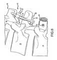
- FIG. 6is an enlarged side plan view of a portion of the spinal stabilization system of the present invention shown in FIG. 3 showing an upper portion of the stabilization system affixed to a spinal column;
- FIG. 7is a side perspective view of a portion of the spinal stabilization system shown in FIG. 6 ;
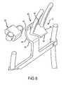
- FIG. 8is an exploded front perspective view of a portion of the spinal stabilization system shown in FIGS. 6 and 7 ;
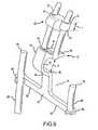
- FIG. 9is an exploded rear perspective view of a portion of the spinal stabilization system shown in FIGS. 6, 7 and 8 ;
- FIG. 10is a front plan view of a spinal stabilization system of the present invention affixed to a spinal column;
- FIG. 11is a bottom front perspective view of a spinal stabilization system of the present invention affixed to a spinal column;
- FIG. 12is a top front perspective view of a spinal stabilization system of the present invention affixed to a spinal column;
- FIG. 13is a side perspective view of a spinal stabilization system of the present invention affixed to a spinal column.
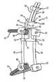
- a spinal stabilization systemaccording to an embodiment of the present invention is shown generally at 10 (which for purposes of brevity will be referred to herein as “the system”).
- the systemincludes a first interlaminar member 12 adapted to be positioned between adjacent vertebra in a spinal column. As shown in greater detail in FIGS. 6 and 7 , the interlaminar member 12 is shown positioned between a first vertebra 14 and a second adjacent vertebra 16 in a spinal column 18 .
- the systemfurther includes a second interlaminar member 20 adapted to be positioned between the second vertebra 16 and a third vertebra 22 in the spinal column 18 .
- Both the first and second interlaminar membersare operatively connected to a support structure shown generally at numeral 25 in FIG. 1 .
- the support structure and the first interlaminar memberare integrally formed from a single piece of material such as titanium or stainless steel suitable for use as a medical implant device.
- other means for connecting the interlaminar device to the support structuresuch as hinges, pins, threaded fasteners and the like may also be used without departing from the scope of the invention.
- the support structure 25comprises a pair of support members or guide rods 28 secured to the first interlaminar support member 12 and extending in a direction upwardly therefrom substantially parallel to one another.
- the second interlaminar member 20includes a body portion 21 of a preselected thickness t, which is most clearly illustrated in FIG. 9 . Thickness t is selected based upon the spacing between the second and third vertebrae and is intended to be smaller in size than the spacing to allow for flexion of the spinal column 18 .
- the body portion 21further includes a pair of oppositely positioned ears 30 extending laterally outwardly from the body portion in opposing directions, each of the ears containing an aperture 32 structured and arranged to slideably receive one of the support members or guide rods 28 .
- the second interlaminar memberis movably supported by upwardly extending support members or guide rods, and the position of the second interlaminar member 20 relative to the first interlaminar member 12 may be adjusted depending upon the dimensions of the specific spinal column on which the system is installed and the range of motion desired. Once the position of the second interlaminar member 20 has been selected, it is locked in place by a pair of set screws or other suitable fastening means 34 extending through each of the ears 30 and adapted to releaseably engage the respective guide rod extending therethrough.
- the first interlaminar membercomprises a U-shaped body 40 defined by an elastic midsection 42 , two spaced apart end portions 44 , and a pair of juxtaposed legs 46 , each leg extending substantially parallel to one another from one of the respective ends in a direction generally outwardly away from the spinal column 18 ( FIG. 7 ) and spaced apart a preselected distance d.
- Distance dis determined by the size of the first interlaminar member, which, in turn, is selected based upon the spacing between the first and second vertebrae.
- the first interlaminar memberis intended to fuse the first and second vertebrae.
- the U-shaped body 40is sized to be a tight fit, and the elastic properties of the U-shaped body 40 act as a spring or shock absorber in the interface between the two vertebrae. Further, the uppermost one of the legs 46 is longer than the lower one of the legs, thereby forming a handle 48 which may be used to insert and position the system during surgery.
- the support structure 25further includes a T-shaped frame member 50 operatively connected to the first and second interlaminar members 12 and 20 and extends generally downwardly therefrom in a direction substantially parallel to the spinal column 18 .
- the T-shaped frame memberincludes an elongate body 52 having first and second end portions 54 , 56 , the first end portion being operatively connected to the first interlaminar member 12 , and an elongate cross member 58 .
- the cross memberhas first and second end portions 60 , 62 and a midpoint 64 and is structured and arranged to be connected to the second end portion 56 of the body 52 at approximately the midpoint 64 .
- Each of the ends 60 , 62 of the cross member 58are adapted to receive and adjustably secure first and second support members 66 and 68 respectively.
- each of the end portions 60 , 62have an aperture 70 , 72 formed therein respectively for receiving one of the support members 66 , 68 , each of which may be held in a preselected position by a set screw 74 .
- the support membersare in the form of guide rods 66 , 68 , each guide rod having an upper end 76 and a lower end 78 .
- Each of the upper and lower ends of the support members 66 , 68has a securing device 80 slideably positioned thereon and adapted to be secured thereto by means of set screws 82 .
- each of the securing devicesis shown in the form of a pedicle screw 84 , each pedicle screw being structured and arranged to be secured to one of the vertebra of the spinal column 18 .
- FIGS. 6, 7, and 10-13The installation and operation of the spinal support system 10 of the present invention are illustrated in greater detail in FIGS. 6, 7, and 10-13 .
- the systemadvantageously may be installed where other spinal fusion devices or similar medical apparatus are already in place to add stability to the spinal column above and below the installation point, to control flexion and/or rotational movement of the spine or selected vertebrae with respect to one another, and to prevent impingement of adjacent vertebrae, spinal processes, pedicle screws and medical hardware on one another.
- a surgeonmay insert the system 25 into the space between adjacent vertebrae 14 and 16 by gripping handle 48 and making the insertion.
- the tight fitting U-shaped body 40not only serves to control any motion between the adjacent vertebrae or even eliminate it entirely, thereby effectively fusing the vertebrae, but also serves as a dampening cushion or spring device by virtue of the spring-like elasticity of the body 40 translated to the vertebrae via legs 46 .
- the second interlaminar member 20may be selectively positioned intermediate vertebra 16 and vertebra 22 to permit flexion on a forward direction but to limit extension in the rearward direction and to limit compression of the spinal segment, thereby imparting enhanced stability to the spinal column above the fused vertebrae.
- support structure 25via the T-shaped frame member 50 and support members or guide rods 66 and 68 , provides support to the spinal processes located below the fused vertebrae 14 and 16 .
- the pedicle screws 80may be positioned in first vertebra 14 and in either vertebra 15 immediately adjacent to vertebra 14 , or at a lower level as shown by vertebra 17 , thus extending the stabilizing effect of the novel support system of the present invention to multiple levels in the spinal column 18 . More than one level may be addressed simply by lengthening the rods 66 and 68 and slideably positioning multiple pedicle screws 80 thereon for selective positioning along the spinal column.
- the cross member midpoint 64may be configured, structured and arranged to be adjustably (e.g., pivotably or translatably) connected or secured to the second end portion 56 of the body 52 at approximately the midpoint 64 in order to allow a surgeon during the course of the surgical procedure to adjust and align components of the implant in relation to the patient's bony anatomy and in relation to support members 66 and 68 .
- elongate body 52may be comprised of multiple pieces.
- one or more linear racksmay be configured in operable relation with gear mechanisms, thereby forming a ratchet device (not shown), in order to extend the distance between first and second end portions 54 and 56 thereby permitting a surgeon during the course of the surgical procedure to adjust and align components of the implant in relation to the patient's bony anatomy and subsequently securing them in place.
- a ratchet mechanism configurationmay permit the surgeon to progressively extend elements of the implant to better appose a lamina.
- each of the ends 60 , 62 of the cross member 58may be configured to permit a degree of adjustability (e.g., pivotably or translatably) to receive and adjustably secure first and second support members 66 and 68 respectively.
- a degree of adjustabilitye.g., pivotably or translatably
- any cross-link variable adjustment mechanism or fastener known in the artmay be employed to accomplish the desired fixation between the ends 60 , 62 of the cross member 58 and first and second support members 66 and 68 .
- interlaminar member 20may be configured to permit connection to guide rods 28 via an approach that is substantially perpendicular to the longitudinal axis of guide rods 28 .
- the interlaminar member 20may follow a generally similar approach trajectory and then be secured to the guide rods 28 with, e.g., set screws in a similar manner to the engagement between the ends 60 , 62 of the cross member 58 and first and second support members 66 and 68 .
- an interlaminar member 20may be used alone (and may alternatively be configured to be similar to the U-shaped body 40 ) and may be directly engaged with a first and second support members 66 and 68 and positioned between the lamina and spinous processes of the spine.
- the different elements of the systemmay be configured with tool engagement features in order to permit a surgeon to grasp the implant with a tool assembly or insertion tool to ease implantation of the various components.
- the insertion toolmay be configured as a pair of pliers or hemostats.
- a threaded portion of a tool assemblymay reversibly secure to a complementary threaded portion of the implant in order to ease implantation.
- a tool assemblymay be comprised of a cannulated shaft with a retainer shaft housed substantially within, the retainer shaft further configured with a threaded portion at its distal end which may extend out of a distal end of the retainer shaft and a handle located and attached to a proximal end of the retainer shaft; the distal end of the retainer shaft may have a feature that permits rotation of the retainer shaft via another tool, such as the mechanical arrangement that exists between a wrench and nut, in order to secure the tool assembly to the implant. After implantation of the implant the tool assembly may be decoupled and removed.
Landscapes
- Health & Medical Sciences (AREA)
- Orthopedic Medicine & Surgery (AREA)
- Life Sciences & Earth Sciences (AREA)
- Neurology (AREA)
- Surgery (AREA)
- Heart & Thoracic Surgery (AREA)
- Engineering & Computer Science (AREA)
- Biomedical Technology (AREA)
- Nuclear Medicine, Radiotherapy & Molecular Imaging (AREA)
- Medical Informatics (AREA)
- Molecular Biology (AREA)
- Animal Behavior & Ethology (AREA)
- General Health & Medical Sciences (AREA)
- Public Health (AREA)
- Veterinary Medicine (AREA)
- Surgical Instruments (AREA)
- Prostheses (AREA)
Abstract
Description
This application is a continuation of U.S. patent application Ser. No. 15/332,947, filed Oct. 24, 2016, which is a continuation of U.S. patent application Ser. No. 14/209,138, filed Mar. 13, 2014, which claims the benefit of U.S. Provisional Application No. 61/794,543, filed Mar. 15, 2013; the entire disclosures of which are incorporated herein by reference.
The present invention relates generally to the field of medical apparatus and methods for using the same. More specifically, the present invention relates to systems and methods for treating spinal conditions, and specifically for systems for stabilizing vertebrae in the spinal column. More specifically, the present invention relates to interlaminar vertebral stabilization devices for placement between adjacent vertebra and including supporting devices for stabilization of the vertebral segments above and below the vertebra being treated.
Injury to and/or diseases of the spine frequently result in damage to or abnormalities in the vertebrae, the intervertebral discs, the facet joints and to the connective tissue and ligaments around the spine. Such damage or abnormalities may result in spinal instability causing misalignment of the vertebral column and wear of the intervertebral discs and vertebral bony surfaces, a chronic and progressive deterioration which typically results in severe pain, loss or restriction of motion, and eventually, loss of mobility of the individual suffering from the condition.
One treatment option for addressing spinal disorders is via surgical intervention and the placement of fusion, stabilization and/or repair devices on or adjacent to the spine or between adjacent vertebrae. Certain surgical procedures are irreversible, for example, fusion techniques using bone grafts or synthetic implants to fuse vertebra, and may also significantly alter vertebral range of motion. Other procedures, for example procedures for installing spinal implants or pedicle screw systems for fixating two or more vertebrae, are intricate, time consuming and highly invasive. Alternative solutions include the insertion of interspinous or intra-laminar spacers in the space between adjacent vertebrae to control relative motion between and to stabilize the two vertebrae. However, the stabilization does not extend above or below the insertion point, leaving the remaining portions of the spinal column subject to unstable motion and the potential damage resulting therefrom.
Various prior art systems have attempted to address the problems described above. U.S. Pat. No. 5,645,599 issued to Samani on Jul. 8, 1997 (the '599 patent), discloses an interspinal implant device having a generally u-shaped, spring-like configuration for insertion between the spinal processes of adjacent vertebrae. Samani's device includes opposing pairs of upwardly and downwardly extending brackets adapted to be secured to the spinal process, thereby providing for flexible positioning of the adjacent vertebrae. However, the apparatus of the '599 patent does not attribute to the overall stability of the spinal column; its effect being limited to the two specific vertebrae to which it is attached. It is also difficult to attach multiple devices configured in accordance with Samani's disclosure at adjacent segments due to interference of the bracket portions.
Hochschuler et al disclose various intra-laminar stabilization systems in U.S. Patent Application Publication No. US 2009/0204150 published on Aug. 13, 2009 (the '150 publication), and in U.S. Patent Application Publication No. US 2011/0106163 published on May 5, 2011 (the '163 publication). The '150 publication discloses a pair of oppositely disposed hook members that are translationally positioned on a rod and adapted to engage the laminar regions of adjacent vertebra and maintain a preselected spacing there between. However, the apparatus of the '150 publication does not stabilize other vertebrae in the spinal column, its effect being limited to the two adjacent vertebrae which it engages.
The Hochschuler et al. '163 publication discloses an interlaminar stabilizing system which includes a structure adapted to be disposed between two adjacent vertebrae as described above with respect to the apparatus of the '150 publication. The '163 structure further includes a support structure which is secured to the second vertebra to further restrict the interval spacing between the adjacent vertebrae. However, the system of the '163 disclosure also does not stabilize the vertebrae in the remaining portions of the spinal column for the reasons set forth above.
Moreover, none of the known prior art systems address the problem of “transition syndrome” or “adjacent segment disease” associated with fusion of adjacent vertebrae. In fusion, if a motion segment is eliminated via fusion, the unfused adjacent segments above and below the fused vertebrae take up and bear the additional forces induced by bending and rotational movement of the spine, which may result in so-called “transition syndrome” over the long term. In addition, none of the prior art systems provide for augmenting previously installed spinal hardware to enhance stability, adjust intervertebral distraction, and so forth.
Accordingly, a need exists for an improved spinal stabilization system which provides both flexibility and stability to the spinal column and which addresses the combination of problems not solved by the prior art.
The stated problems and other needs in the art as apparent from the foregoing background may be addressed in accordance with the systems and methods of the present invention as set forth in various embodiments disclosed herein.
In an embodiment, an improved spinal stabilization system is provided for maintaining preselected spacing and movement between adjacent vertebrae and also for providing overall stability to the spinal column.
In one embodiment, a spinal stabilization system is provided which includes at least one interlaminar member adapted to be inserted between two adjacent vertebrae and a stabilizing structure for stabilizing the vertebrae at least one layer above and below the two adjacent vertebrae.
In another embodiment, a spinal stabilization system is provided which includes a blocking member to limit movement of adjacent vertebrae to prevent narrowing of the spinal canal and nerve compression.
In yet another embodiment, a spinal stabilization system is provided which includes at least one adjustable cross-linking member to enhance stability of the spine.
In still another embodiment, a method for treating a patient's spinal column is disclosed employing at least one of the embodiments of the spinal stabilization system of the present invention.
These and other features of the present invention will be apparent from the accompanying description of the invention, diagrams and supplemental supporting materials provided herein.
It should be noted that the present description is by way of illustration only, and that the concepts and examples presented herein are not limited to use or application with any single system or methodology. Hence, while the details of the system and methods described herein are for the convenience of illustration and explanation with respect to the exemplary embodiments, the principles disclosed may be applied to other types of spinal stabilization systems without departing from the scope of the present invention.
Referring now toFIG. 1 , a spinal stabilization system according to an embodiment of the present invention is shown generally at10 (which for purposes of brevity will be referred to herein as “the system”). The system includes a firstinterlaminar member 12 adapted to be positioned between adjacent vertebra in a spinal column. As shown in greater detail inFIGS. 6 and 7 , theinterlaminar member 12 is shown positioned between afirst vertebra 14 and a secondadjacent vertebra 16 in aspinal column 18.
The system further includes a secondinterlaminar member 20 adapted to be positioned between thesecond vertebra 16 and athird vertebra 22 in thespinal column 18. Both the first and second interlaminar members are operatively connected to a support structure shown generally atnumeral 25 inFIG. 1 . By way of example, in the embodiment shown, the support structure and the first interlaminar member are integrally formed from a single piece of material such as titanium or stainless steel suitable for use as a medical implant device. However, it is to be understood that other means for connecting the interlaminar device to the support structure such as hinges, pins, threaded fasteners and the like may also be used without departing from the scope of the invention.
Thesupport structure 25 comprises a pair of support members or guiderods 28 secured to the firstinterlaminar support member 12 and extending in a direction upwardly therefrom substantially parallel to one another. Thesecond interlaminar member 20 includes abody portion 21 of a preselected thickness t, which is most clearly illustrated inFIG. 9 . Thickness t is selected based upon the spacing between the second and third vertebrae and is intended to be smaller in size than the spacing to allow for flexion of thespinal column 18.
Thebody portion 21 further includes a pair of oppositely positionedears 30 extending laterally outwardly from the body portion in opposing directions, each of the ears containing anaperture 32 structured and arranged to slideably receive one of the support members or guiderods 28. As will be discussed in greater detail below, the second interlaminar member is movably supported by upwardly extending support members or guide rods, and the position of thesecond interlaminar member 20 relative to the firstinterlaminar member 12 may be adjusted depending upon the dimensions of the specific spinal column on which the system is installed and the range of motion desired. Once the position of thesecond interlaminar member 20 has been selected, it is locked in place by a pair of set screws or other suitable fastening means34 extending through each of theears 30 and adapted to releaseably engage the respective guide rod extending therethrough.
Referring now toFIGS. 2, 3, 7 and 8 , the first interlaminar member is12 depicted in greater detail. The first interlaminar member comprises aU-shaped body 40 defined by anelastic midsection 42, two spaced apart endportions 44, and a pair ofjuxtaposed legs 46, each leg extending substantially parallel to one another from one of the respective ends in a direction generally outwardly away from the spinal column18 (FIG. 7 ) and spaced apart a preselected distance d. Distance d is determined by the size of the first interlaminar member, which, in turn, is selected based upon the spacing between the first and second vertebrae. The first interlaminar member is intended to fuse the first and second vertebrae. Accordingly, it is sized to be a tight fit, and the elastic properties of theU-shaped body 40 act as a spring or shock absorber in the interface between the two vertebrae. Further, the uppermost one of thelegs 46 is longer than the lower one of the legs, thereby forming ahandle 48 which may be used to insert and position the system during surgery.
Referring again toFIG. 1 , thesupport structure 25 further includes a T-shapedframe member 50 operatively connected to the first and secondinterlaminar members spinal column 18. The T-shaped frame member includes anelongate body 52 having first andsecond end portions interlaminar member 12, and anelongate cross member 58. The cross member has first andsecond end portions midpoint 64 and is structured and arranged to be connected to thesecond end portion 56 of thebody 52 at approximately themidpoint 64. Each of theends cross member 58 are adapted to receive and adjustably secure first andsecond support members end portions aperture support members set screw 74.
In the embodiment shown, by way of example only and not of limitation, the support members are in the form ofguide rods upper end 76 and alower end 78. Each of the upper and lower ends of thesupport members device 80 slideably positioned thereon and adapted to be secured thereto by means of set screws82. By way of example, each of the securing devices is shown in the form of apedicle screw 84, each pedicle screw being structured and arranged to be secured to one of the vertebra of thespinal column 18.
The installation and operation of thespinal support system 10 of the present invention are illustrated in greater detail inFIGS. 6, 7, and 10-13 . The system advantageously may be installed where other spinal fusion devices or similar medical apparatus are already in place to add stability to the spinal column above and below the installation point, to control flexion and/or rotational movement of the spine or selected vertebrae with respect to one another, and to prevent impingement of adjacent vertebrae, spinal processes, pedicle screws and medical hardware on one another. By way of example, as best shown inFIGS. 6 and 7 , a surgeon may insert thesystem 25 into the space betweenadjacent vertebrae handle 48 and making the insertion. The tight fittingU-shaped body 40 not only serves to control any motion between the adjacent vertebrae or even eliminate it entirely, thereby effectively fusing the vertebrae, but also serves as a dampening cushion or spring device by virtue of the spring-like elasticity of thebody 40 translated to the vertebrae vialegs 46. Thereafter, thesecond interlaminar member 20 may be selectively positionedintermediate vertebra 16 andvertebra 22 to permit flexion on a forward direction but to limit extension in the rearward direction and to limit compression of the spinal segment, thereby imparting enhanced stability to the spinal column above the fused vertebrae.
In a similar manner,support structure 25, via the T-shapedframe member 50 and support members or guiderods vertebrae FIGS. 10-13 , the pedicle screws80 may be positioned infirst vertebra 14 and in eithervertebra 15 immediately adjacent tovertebra 14, or at a lower level as shown byvertebra 17, thus extending the stabilizing effect of the novel support system of the present invention to multiple levels in thespinal column 18. More than one level may be addressed simply by lengthening therods
In one aspect, thecross member midpoint 64 may be configured, structured and arranged to be adjustably (e.g., pivotably or translatably) connected or secured to thesecond end portion 56 of thebody 52 at approximately themidpoint 64 in order to allow a surgeon during the course of the surgical procedure to adjust and align components of the implant in relation to the patient's bony anatomy and in relation to supportmembers
In another aspect,elongate body 52 may be comprised of multiple pieces. For example, one or more linear racks may be configured in operable relation with gear mechanisms, thereby forming a ratchet device (not shown), in order to extend the distance between first andsecond end portions
In yet another aspect, each of theends cross member 58 may be configured to permit a degree of adjustability (e.g., pivotably or translatably) to receive and adjustably secure first andsecond support members ends cross member 58 and first andsecond support members
According to particular embodiments,interlaminar member 20 may be configured to permit connection to guiderods 28 via an approach that is substantially perpendicular to the longitudinal axis ofguide rods 28. In other words, after the other components of the system have been implanted via a posterior approach to the posterior aspect of the spine, theinterlaminar member 20 may follow a generally similar approach trajectory and then be secured to theguide rods 28 with, e.g., set screws in a similar manner to the engagement between theends cross member 58 and first andsecond support members interlaminar member 20 may be used alone (and may alternatively be configured to be similar to the U-shaped body40) and may be directly engaged with a first andsecond support members
In particular aspects, the different elements of the system may be configured with tool engagement features in order to permit a surgeon to grasp the implant with a tool assembly or insertion tool to ease implantation of the various components. For example, the insertion tool may be configured as a pair of pliers or hemostats. As another example, a threaded portion of a tool assembly may reversibly secure to a complementary threaded portion of the implant in order to ease implantation. E.g., a tool assembly may be comprised of a cannulated shaft with a retainer shaft housed substantially within, the retainer shaft further configured with a threaded portion at its distal end which may extend out of a distal end of the retainer shaft and a handle located and attached to a proximal end of the retainer shaft; the distal end of the retainer shaft may have a feature that permits rotation of the retainer shaft via another tool, such as the mechanical arrangement that exists between a wrench and nut, in order to secure the tool assembly to the implant. After implantation of the implant the tool assembly may be decoupled and removed.
Changes may be made in the above methods and systems without departing from the scope hereof. It should thus be noted that the matter contained in the above description and/or shown in the accompanying figures should be interpreted as illustrative and not in a limiting sense. The following claims are intended to cover all generic and specific features described herein, as well as all statements of the scope of the present systems and methods, which, as a matter of language, might be said to fall there between.
Claims (17)
1. A spinal stabilization system for treating a spinal column having a first vertebra and a second vertebra, the system comprising:
an interlaminar member adapted to be positioned between the first vertebra and the second vertebra; the interlaminar member including a U-shaped body having a midsection, and two spaced apart end portions, and a pair of juxtaposed legs extending substantially parallel to one another from the U-shaped body, each of the pair of juxtaposed legs having a first end connected to one of the two respective spaced apart end portions of the U-shaped body, each leg including a second end located opposite the first end;
a support structure operatively connected to the interlaminar member, the support structure including a T-shaped frame member operatively connected to the interlaminar member and extending generally downwardly therefrom, the T-shaped frame member including an elongate body having first and second end portions, the first end portion of the elongate body being operatively connected to the interlaminar member at the second end of one of the pair of juxtaposed legs, and an elongate cross member having first and second end portions and a midpoint, the elongate cross member being operatively connected approximately at the midpoint to the second end portion of the elongate body.
2. The system ofclaim 1 further including first and second guide rods adjustably secured to the first and second ends of the elongate cross member respectively.
3. The system ofclaim 2 where each of the first and second guide rods includes an upper and a lower end, each of the upper and lower ends having a securing device slideably positioned thereon, each securing device being structured and arranged to be secured to a vertebra in the spinal column.
4. The system ofclaim 2 , wherein each of the first and second end portions of the elongate cross member further includes an aperture formed therein configured to pivotably and/or translatably receive a respective one of the first and second guide rods and a fastener adapted to the respective one of the first and second guide rods in a preselected position.
5. The system ofclaim 1 , wherein the elongate body includes at least one linear rack, the rack being structured and arranged to progressively extend the distance between the first and second end portions of the elongate body of the T-shaped frame member.
6. The system ofclaim 5 , further including a gear mechanism operatively connected to the at least one linear rack, the gear mechanism and the at least one linear rack forming a ratchet device configured to permit the progressive extension.
7. The system ofclaim 1 wherein the support structure includes a pair of support members secured to the interlaminar member at one of the pair of juxtaposed legs, the leg being opposite the leg to which the elongate body is attached, the support members extending upwardly therefrom in a direction substantially parallel to one another.
8. The system ofclaim 1 wherein the interlaminar member is structured and arranged to fit tightly between the first vertebra and the second vertebra.
9. The system ofclaim 1 , wherein the midsection is elastic.
10. The system ofclaim 1 , wherein the support structure and the interlaminar member are integrally formed from a single piece of material.
11. A system for treating a patient's spinal column, the system comprising:
a spinal stabilization system including an interlaminar member adapted to be positioned between a first vertebra and a second vertebra in a spinal column; the interlaminar member including a U-shaped body having a midsection, and two spaced apart end portions, and a pair of juxtaposed legs extending substantially parallel to one another from one of the respective ends in a direction generally outwardly away from the spinal column;
a support structure operatively connected to the interlaminar member and adapted to be connected to the first vertebra and at least one vertebra positioned below the first vertebra in the spinal column, the support structure including a T-shaped frame member operatively connected to the interlaminar member and extending generally downwardly therefrom in a direction substantially parallel to the direction of the spinal column, the T-shaped frame member including an elongate body having first and second end portions, the first end portion being operatively connected to the interlaminar member, and an elongate cross member having first and second end portions and a midpoint, the elongate cross member being operatively connected approximately at the midpoint to the second end portion of the body and
an insertion tool configured to reversibly secure to a tool engagement portion of the spinal stabilization system,
the insertion tool being adapted to permit a surgeon to grasp the system with the insertion tool whereby implantation of the system in the patient's spinal column is facilitated.
12. The system ofclaim 11 , wherein the insertion tool comprises a pair of pliers or hemostats.
13. The system ofclaim 12 , wherein the tool engagement portion includes a threaded portion and wherein the insertion tool includes a threaded portion configured to reversibly secure to the threaded portion of the tool engagement portion of the spinal stabilization system.
14. The system ofclaim 13 , wherein the insertion tool includes a cannulated shaft and a retainer shaft housed substantially within the cannulated shaft, the retainer shaft including a distal end and a proximal end opposite the distal end, the distal end of the retainer shaft comprising the threaded portion thereof and the proximal end of the retainer shaft comprising a handle.
15. A spinal stabilization system comprising: an interlaminar member adapted to be positioned between a first vertebra and a second vertebra in a spinal column; the interlaminar member including a U-shaped body having a midsection, and two spaced apart end portions, and a pair of juxtaposed legs extending substantially parallel to one another from one of the respective ends in a direction generally outwardly away from the spinal column; a support structure operatively connected to the interlaminar member, the first vertebra and at least one vertebra positioned below the first vertebra in the spinal column, the support structure including a T-shaped frame member operatively connected to the interlaminar member and extending generally downwardly therefrom in a direction substantially parallel to the direction of the spinal column, the T-shaped frame member including an elongate body having first and second end portions, the first end portion being operatively connected to the interlaminar member, and an elongate cross member having first and second end portions and a midpoint, the elongate cross member being operatively connected approximately at the midpoint to the second end portion of the body; wherein the pair of juxtaposed legs comprises an uppermost leg and a lowermost leg, the first end portion of the elongate body being operatively connected to the interlaminar member at the lowermost leg and wherein the uppermost leg is longer that the lowermost leg.
16. The system ofclaim 15 , wherein the uppermost leg forms a handle adapted to facilitate insertion and positioning of the system during surgery.
17. A spinal stabilization system for treating a spinal column having a first vertebra and a second vertebra positioned adjacent the first vertebra, the system comprising: an interlaminar member adapted to be positioned between the first vertebra and the second vertebra; the interlaminar member including a U-shaped body having a midsection, and two spaced apart end portions, and a pair of juxtaposed legs, each leg having a first end connected at each spaced apart end portion, respectively, and extending generally parallel to one another from each one of the respective ends and each leg having a second end opposite the first end; a support structure operatively connected to the interlaminar member, the support structure including a T-shaped frame member operatively connected to the interlaminar member and extending generally downwardly therefrom, the T-shaped frame member including an elongate body having first and second end portions, the first end portion of the elongate body being operatively connected to the interlaminar member, and an elongate cross member having first and second end portions and a midpoint, the elongate cross member being operatively connected approximately at the midpoint to the second end portion of the body of the elongate body;
wherein the T-shaped frame is defined by a first plane, the U-shaped body is defined in a second plane and wherein an arrangement between the T-shaped frame and U-shaped body is such that the first plane is generally perpendicular to the second plane.
Priority Applications (2)
| Application Number | Priority Date | Filing Date | Title |
|---|---|---|---|
| US15/408,157US9795419B2 (en) | 2013-03-15 | 2017-01-17 | Spinal stabilization system |
| US15/711,156US10548643B2 (en) | 2013-03-15 | 2017-09-21 | Spinal stabilization system |
Applications Claiming Priority (4)
| Application Number | Priority Date | Filing Date | Title |
|---|---|---|---|
| US201361794543P | 2013-03-15 | 2013-03-15 | |
| US14/209,138US9510872B2 (en) | 2013-03-15 | 2014-03-13 | Spinal stabilization system |
| US15/332,947US9603638B2 (en) | 2013-03-15 | 2016-10-24 | Spinal stabilization system |
| US15/408,157US9795419B2 (en) | 2013-03-15 | 2017-01-17 | Spinal stabilization system |
Related Parent Applications (1)
| Application Number | Title | Priority Date | Filing Date |
|---|---|---|---|
| US15/332,947ContinuationUS9603638B2 (en) | 2013-03-15 | 2016-10-24 | Spinal stabilization system |
Related Child Applications (1)
| Application Number | Title | Priority Date | Filing Date |
|---|---|---|---|
| US15/711,156ContinuationUS10548643B2 (en) | 2013-03-15 | 2017-09-21 | Spinal stabilization system |
Publications (2)
| Publication Number | Publication Date |
|---|---|
| US20170119440A1 US20170119440A1 (en) | 2017-05-04 |
| US9795419B2true US9795419B2 (en) | 2017-10-24 |
Family
ID=51537696
Family Applications (4)
| Application Number | Title | Priority Date | Filing Date |
|---|---|---|---|
| US14/209,138ActiveUS9510872B2 (en) | 2013-03-15 | 2014-03-13 | Spinal stabilization system |
| US15/332,947ActiveUS9603638B2 (en) | 2013-03-15 | 2016-10-24 | Spinal stabilization system |
| US15/408,157ActiveUS9795419B2 (en) | 2013-03-15 | 2017-01-17 | Spinal stabilization system |
| US15/711,156ActiveUS10548643B2 (en) | 2013-03-15 | 2017-09-21 | Spinal stabilization system |
Family Applications Before (2)
| Application Number | Title | Priority Date | Filing Date |
|---|---|---|---|
| US14/209,138ActiveUS9510872B2 (en) | 2013-03-15 | 2014-03-13 | Spinal stabilization system |
| US15/332,947ActiveUS9603638B2 (en) | 2013-03-15 | 2016-10-24 | Spinal stabilization system |
Family Applications After (1)
| Application Number | Title | Priority Date | Filing Date |
|---|---|---|---|
| US15/711,156ActiveUS10548643B2 (en) | 2013-03-15 | 2017-09-21 | Spinal stabilization system |
Country Status (3)
| Country | Link |
|---|---|
| US (4) | US9510872B2 (en) |
| EP (1) | EP2967651B1 (en) |
| WO (1) | WO2014144379A1 (en) |
Families Citing this family (37)
| Publication number | Priority date | Publication date | Assignee | Title |
|---|---|---|---|---|
| US20180228621A1 (en) | 2004-08-09 | 2018-08-16 | Mark A. Reiley | Apparatus, systems, and methods for the fixation or fusion of bone |
| US9949843B2 (en) | 2004-08-09 | 2018-04-24 | Si-Bone Inc. | Apparatus, systems, and methods for the fixation or fusion of bone |
| US9814493B2 (en)* | 2009-10-12 | 2017-11-14 | Globus Medical, Inc. | Trans-iliac connector |
| EP2814410B1 (en)* | 2012-02-17 | 2019-05-01 | The University of Toledo | Hybrid multifunctional posterior interspinous fusion device |
| US10363140B2 (en) | 2012-03-09 | 2019-07-30 | Si-Bone Inc. | Systems, device, and methods for joint fusion |
| US9044321B2 (en) | 2012-03-09 | 2015-06-02 | Si-Bone Inc. | Integrated implant |
| EP3818947B1 (en) | 2012-05-04 | 2023-08-30 | SI-Bone, Inc. | Fenestrated implant |
| WO2013177314A1 (en)* | 2012-05-22 | 2013-11-28 | The Regents Of The University Of California | A method and device for restabilization with axial rotation of the atlantoaxial junction |
| US11213325B2 (en)* | 2013-03-15 | 2022-01-04 | Jcbd, Llc | Spinal stabilization system with adjustable interlaminar devices |
| US20140277163A1 (en)* | 2013-03-15 | 2014-09-18 | Ryan Kretzer | Reinforcement systems for spine stabilization constructs |
| WO2014145902A1 (en) | 2013-03-15 | 2014-09-18 | Si-Bone Inc. | Implants for spinal fixation or fusion |
| US9839448B2 (en) | 2013-10-15 | 2017-12-12 | Si-Bone Inc. | Implant placement |
| US11147688B2 (en) | 2013-10-15 | 2021-10-19 | Si-Bone Inc. | Implant placement |
| US10166033B2 (en) | 2014-09-18 | 2019-01-01 | Si-Bone Inc. | Implants for bone fixation or fusion |
| JP6542362B2 (en) | 2014-09-18 | 2019-07-10 | エスアイ−ボーン・インコーポレイテッドSi−Bone, Inc. | Matrix implant |
| EP3203921B1 (en)* | 2014-10-09 | 2020-03-18 | Spinal Developments Pty Ltd | Spinal alignment and securement |
| CN104706404B (en)* | 2015-03-16 | 2017-11-14 | 吴晓波 | A kind of orthopedic vertebral body repositioning device |
| US10376206B2 (en) | 2015-04-01 | 2019-08-13 | Si-Bone Inc. | Neuromonitoring systems and methods for bone fixation or fusion procedures |
| ITUB20156306A1 (en)* | 2015-12-03 | 2017-06-03 | Medacta Int Sa | EQUIVALENT-CERVICAL FIXING EQUIPMENT |
| WO2018027676A1 (en)* | 2016-08-10 | 2018-02-15 | 北京爱康宜诚医疗器材有限公司 | Artificial vertebral body fixing system |
| CN106264699A (en)* | 2016-08-28 | 2017-01-04 | 李海洋 | Pedicle screw |
| US10463403B2 (en) | 2017-07-31 | 2019-11-05 | Medos International Sarl | Systems and methods for reducing the risk of proximal junctional kyphosis using a bone anchor or other attachment point |
| US10456174B2 (en)* | 2017-07-31 | 2019-10-29 | Medos International Sarl | Connectors for use in systems and methods for reducing the risk of proximal junctional kyphosis |
| JP7218360B2 (en) | 2017-09-22 | 2023-02-06 | メドス・インターナショナル・エスエイアールエル | patient-worn surgical support |
| US11559372B2 (en) | 2017-09-22 | 2023-01-24 | Medos International Sarl | Patient-mounted surgical retractor |
| US11116519B2 (en) | 2017-09-26 | 2021-09-14 | Si-Bone Inc. | Systems and methods for decorticating the sacroiliac joint |
| ES3011907T3 (en) | 2018-03-28 | 2025-04-08 | Si Bone Inc | Threaded implants for use across bone segments |
| EP4613244A2 (en) | 2019-02-14 | 2025-09-10 | SI-Bone Inc. | Implants for spinal fixation and or fusion |
| US11369419B2 (en) | 2019-02-14 | 2022-06-28 | Si-Bone Inc. | Implants for spinal fixation and or fusion |
| JP7646654B2 (en) | 2019-11-21 | 2025-03-17 | エスアイ-ボーン・インコーポレイテッド | Rod coupling assembly for bone stabilization construct - Patent application |
| US11204060B2 (en) | 2019-11-27 | 2021-12-21 | Medos International Sari | Selectively lockable ball and socket joint |
| AU2020392121B2 (en) | 2019-11-27 | 2025-05-22 | Si-Bone, Inc. | Bone stabilizing implants and methods of placement across SI joints |
| US11229464B2 (en) | 2019-12-04 | 2022-01-25 | Medos International Sarl | Apparatus for driver-specific backout prevention |
| EP4072452A4 (en) | 2019-12-09 | 2023-12-20 | SI-Bone, Inc. | Sacro-iliac joint stabilizing implants and methods of implantation |
| EP4259015A4 (en) | 2020-12-09 | 2024-09-11 | SI-Bone, Inc. | SACROILIAC JOINT STABILIZATION IMPLANTS AND METHODS OF IMPLANTATION |
| US11980398B2 (en) | 2021-11-18 | 2024-05-14 | Astura Medical Inc | Crosslink locking mechanism |
| WO2025038769A1 (en) | 2023-08-15 | 2025-02-20 | Si-Bone Inc. | Pelvic stabilization implants, methods of use and manufacture |
Citations (49)
| Publication number | Priority date | Publication date | Assignee | Title |
|---|---|---|---|---|
| US20020116000A1 (en)* | 1998-10-20 | 2002-08-22 | Zucherman James F. | Supplemental spine fixation device and method |
| US20020147449A1 (en)* | 2001-04-09 | 2002-10-10 | David Yun | Spine fixation device and method |
| US20050033434A1 (en)* | 2003-08-06 | 2005-02-10 | Sdgi Holdings, Inc. | Posterior elements motion restoring device |
| US20050131409A1 (en)* | 2003-12-10 | 2005-06-16 | Alan Chervitz | Linked bilateral spinal facet implants and methods of use |
| US20060217718A1 (en)* | 2005-03-28 | 2006-09-28 | Facet Solutions, Inc. | Facet joint implant crosslinking apparatus and method |
| US20060224159A1 (en)* | 2005-03-31 | 2006-10-05 | Sdgi Holdings, Inc. | Intervertebral prosthetic device for spinal stabilization and method of implanting same |
| US20060241601A1 (en)* | 2005-04-08 | 2006-10-26 | Trautwein Frank T | Interspinous vertebral and lumbosacral stabilization devices and methods of use |
| WO2007052975A1 (en) | 2005-11-03 | 2007-05-10 | Dong-Kyu Chin | Fixing device for spinous process |
| US20070162000A1 (en)* | 2005-11-22 | 2007-07-12 | Richard Perkins | Adjustable spinous process spacer device and method of treating spinal stenosis |
| US20070233068A1 (en)* | 2006-02-22 | 2007-10-04 | Sdgi Holdings, Inc. | Intervertebral prosthetic assembly for spinal stabilization and method of implanting same |
| US20070233129A1 (en)* | 2006-02-17 | 2007-10-04 | Rudolf Bertagnoli | Method and system for performing interspinous space preparation for receiving an implant |
| US20080015609A1 (en)* | 2006-04-28 | 2008-01-17 | Trautwein Frank T | Instrument system for use with an interspinous implant |
| US20080228225A1 (en)* | 2006-11-30 | 2008-09-18 | Paradigm Spine, Llc | Interlaminar-Interspinous Vertebral Stabilization System |
| US20080269904A1 (en)* | 2007-04-26 | 2008-10-30 | Voorhies Rand M | Lumbar disc replacement implant for posterior implantation with dynamic spinal stabilization device and method |
| US20080281361A1 (en)* | 2007-05-10 | 2008-11-13 | Shannon Marlece Vittur | Posterior stabilization and spinous process systems and methods |
| US20080306549A1 (en) | 2007-06-05 | 2008-12-11 | Spartek Medical, Inc. | Rod capture mechanism for dynamic stabilization and motion preservation spinal implantation system and method |
| US20090018662A1 (en)* | 2005-08-26 | 2009-01-15 | Abbott Laboratories | Intervertebral implant for the lumbosacral joint |
| US20090024169A1 (en)* | 2004-06-02 | 2009-01-22 | Facet Solutions, Inc. | System and method for multiple level facet joint arthroplasty and fusion |
| US20090138048A1 (en)* | 2005-09-21 | 2009-05-28 | Abbott Laboratories | Instrument for tensioning a flexible tie |
| US20090149885A1 (en)* | 2007-12-10 | 2009-06-11 | Custom Spine, Inc. | Spinal flexion and extension motion damper |
| US20090187217A1 (en)* | 2008-01-18 | 2009-07-23 | Mark Weiman | Transverse Connector |
| US20090204151A1 (en)* | 2008-02-07 | 2009-08-13 | Scott Bracken | Spinal implant device, procedure and system |
| US20090216276A1 (en)* | 2005-04-07 | 2009-08-27 | Denis Pasquet | Intervertebral implant for lumbosacral joint |
| US20090270920A1 (en)* | 2008-04-24 | 2009-10-29 | Zimmer Spine S.A.S. | System for Stabilizing at Least a Portion of the Spine |
| US20100049252A1 (en)* | 2008-08-21 | 2010-02-25 | Southern Spine, Llc | Transverse Connector Device for Extending an Existing Spinal Fixation System |
| US20100069965A1 (en)* | 2008-07-05 | 2010-03-18 | Abdou M Samy | Device and method for the prevention of multi-level vertebral extension |
| US20110071568A1 (en)* | 2009-09-24 | 2011-03-24 | Ginn Richard S | Spacer Devices Having Retainers And Systems For The Treatment Of Spinal Stenosis And Methods For Using The Same |
| US20110106163A1 (en)* | 2006-01-23 | 2011-05-05 | Hochschuler Stephen H | Interlaminar Stabilizing System |
| US20110106257A1 (en)* | 2002-03-15 | 2011-05-05 | Paradigm Spine, Llc | Dynamic intervertebral implant |
| US20110137345A1 (en)* | 2009-03-18 | 2011-06-09 | Caleb Stoll | Posterior lumbar fusion |
| US20110160772A1 (en)* | 2009-12-28 | 2011-06-30 | Arcenio Gregory B | Systems and methods for performing spinal fusion |
| US20110218571A1 (en)* | 2007-04-24 | 2011-09-08 | David Attia | Articulated intervertebral surgical implant to encourage certain intervertebral movements |
| US20120065683A1 (en)* | 2010-09-13 | 2012-03-15 | Fan-Ching Kuo | Interspinous process distraction device |
| US20120078303A1 (en)* | 2010-09-27 | 2012-03-29 | Mmsn Limited Partnership | Medical apparatus and method for spinal surgery |
| US20120130427A1 (en)* | 2006-11-28 | 2012-05-24 | Hoffman Zachary M | Adjustable occipital plate |
| US20120136390A1 (en)* | 2010-11-29 | 2012-05-31 | Butler Michael S | Spinal Implants For Lumbar Vertebra To Sacrum Fixation |
| US20120150228A1 (en)* | 2010-12-13 | 2012-06-14 | Jason Zappacosta | Spinous Process Fusion Devices and Methods Thereof |
| US20120158060A1 (en)* | 2010-12-17 | 2012-06-21 | Abrahams John M | Spinal Implant Apparatuses and Methods of Implanting and Using Same |
| US20120215262A1 (en)* | 2011-02-16 | 2012-08-23 | Interventional Spine, Inc. | Spinous process spacer and implantation procedure |
| US20120226312A1 (en)* | 2011-02-06 | 2012-09-06 | Thalgott John S | Translaminar interspinous stabilization system |
| US20120226314A1 (en)* | 2011-03-04 | 2012-09-06 | Spinefrontier Inc | Interspinous spacer implant |
| US20130023933A1 (en)* | 2010-01-27 | 2013-01-24 | Aesculap Ag | Implant for mutually supporting the spinous processes of adjacent vertebral bodies and a surgical system |
| US20130030467A1 (en)* | 2011-07-28 | 2013-01-31 | Chris Karas | Systems, methods, and apparatuses for spinal fixation |
| US20130053854A1 (en)* | 2011-08-31 | 2013-02-28 | Biomet Manufacturing Corp. | Patient-specific sacroiliac guides and associated methods |
| US20130296939A1 (en)* | 2005-11-22 | 2013-11-07 | Richard Perkins | Adjustable spinous process spacer device and method of treating spinal disorders |
| US20130345753A1 (en)* | 2010-04-30 | 2013-12-26 | Neuraxis Technologies LLC | Intersegmental motion preservation system for use in the spine and methods for use thereof |
| US20140074166A1 (en)* | 2012-09-11 | 2014-03-13 | Mercy Medical Research Institute | Spinous process fixation device and systems |
| US20140316467A1 (en)* | 2011-10-31 | 2014-10-23 | Nlt Spine Ltd. | Bony structure fixation clamp |
| US20150012040A1 (en)* | 2012-02-17 | 2015-01-08 | The University Of Toledo | Hybrid Multifunctional Posterior Interspinous Fusion Device |
Family Cites Families (216)
| Publication number | Priority date | Publication date | Assignee | Title |
|---|---|---|---|---|
| GB2084468B (en) | 1980-09-25 | 1984-06-06 | South African Inventions | Surgical implant |
| NO149831C (en) | 1981-11-27 | 1984-07-04 | Per Helland | EXTERNAL CORRECTION AND FIXING EQUIPMENT OF THE KNOCKS |
| US4569338A (en) | 1984-02-09 | 1986-02-11 | Edwards Charles C | Sacral fixation device |
| DE8513288U1 (en) | 1985-05-06 | 1986-09-04 | Wolter, Dietmar, Prof. Dr., 2000 Hamburg | Osteosynthesis plate |
| US4773402A (en) | 1985-09-13 | 1988-09-27 | Isola Implants, Inc. | Dorsal transacral surgical implant |
| US4920958A (en) | 1986-11-05 | 1990-05-01 | Minnesota Mining And Manufacturing Company | Drill guide assembly |
| US4714469A (en) | 1987-02-26 | 1987-12-22 | Pfizer Hospital Products Group, Inc. | Spinal implant |
| US5609635A (en) | 1988-06-28 | 1997-03-11 | Michelson; Gary K. | Lordotic interbody spinal fusion implants |
| US4961740B1 (en) | 1988-10-17 | 1997-01-14 | Surgical Dynamics Inc | V-thread fusion cage and method of fusing a bone joint |
| US4950270A (en) | 1989-02-03 | 1990-08-21 | Boehringer Mannheim Corporation | Cannulated self-tapping bone screw |
| US5458638A (en) | 1989-07-06 | 1995-10-17 | Spine-Tech, Inc. | Non-threaded spinal implant |
| US5192327A (en) | 1991-03-22 | 1993-03-09 | Brantigan John W | Surgical prosthetic implant for vertebrae |
| DE69227204D1 (en) | 1991-05-24 | 1998-11-05 | Kerry Zang | BONE FASTENING DEVICE |
| GB9122753D0 (en) | 1991-10-26 | 1991-12-11 | Reis Nicolas D | Internal ilio-lumbar fixator |
| US5242444A (en) | 1991-11-04 | 1993-09-07 | University Of Florida | Lumbosacral fixation and fusion method and device |
| US5282861A (en) | 1992-03-11 | 1994-02-01 | Ultramet | Open cell tantalum structures for cancellous bone implants and cell and tissue receptors |
| FR2695026B1 (en) | 1992-08-25 | 1994-10-28 | Alexandre Worcel | Device for maintaining compression of a fractured bone. |
| US5443509A (en) | 1992-12-10 | 1995-08-22 | Linvatec Corporation | Interference bone-fixation screw with multiple interleaved threads |
| US5415661A (en)* | 1993-03-24 | 1995-05-16 | University Of Miami | Implantable spinal assist device |
| US5334205A (en) | 1993-06-30 | 1994-08-02 | The United States Of America As Represented By The Secretary Of The Air Force | Sacroiliac joint fixation guide |
| FR2716794B1 (en) | 1994-03-03 | 1996-05-24 | Sofamor Danek Group Inc | Connector for spinal osteosynthesis instrumentation, intended for lumbar or sacral or iliosacral fixation. |
| US5456267A (en) | 1994-03-18 | 1995-10-10 | Stark; John G. | Bone marrow harvesting systems and methods and bone biopsy systems and methods |
| JP3509103B2 (en) | 1994-05-23 | 2004-03-22 | スルザー スパイン−テック インコーポレイテッド | Intervertebral fusion implant |
| FR2722980B1 (en)* | 1994-07-26 | 1996-09-27 | Samani Jacques | INTERTEPINOUS VERTEBRAL IMPLANT |
| FR2729556B1 (en) | 1995-01-23 | 1998-10-16 | Sofamor | SPINAL OSTEOSYNTHESIS DEVICE WITH MEDIAN HOOK AND VERTEBRAL ANCHOR SUPPORT |
| US6206922B1 (en) | 1995-03-27 | 2001-03-27 | Sdgi Holdings, Inc. | Methods and instruments for interbody fusion |
| US5782919A (en) | 1995-03-27 | 1998-07-21 | Sdgi Holdings, Inc. | Interbody fusion device and method for restoration of normal spinal anatomy |
| US5607424A (en) | 1995-04-10 | 1997-03-04 | Tropiano; Patrick | Domed cage |
| US5626434A (en) | 1995-08-21 | 1997-05-06 | Cook; Robert W. | Connector for variable-curvature spaceframe structural system |
| US5772594A (en) | 1995-10-17 | 1998-06-30 | Barrick; Earl F. | Fluoroscopic image guided orthopaedic surgery system with intraoperative registration |
| CN2265765Y (en) | 1996-02-16 | 1997-10-29 | 文益民 | Repositor for fracture and dislocation of sacro-iliac joints |
| US5919193A (en) | 1996-03-14 | 1999-07-06 | Slavitt; Jerome A. | Method and kit for surgically correcting malformations in digits of a finger or toe |
| US5743914A (en) | 1996-06-06 | 1998-04-28 | Skiba; Jeffry B. | Bone screw |
| US5688284A (en) | 1996-09-20 | 1997-11-18 | Medicinelodge, Inc. | Variable angle drill guide and ligament fixation method |
| US6068630A (en) | 1997-01-02 | 2000-05-30 | St. Francis Medical Technologies, Inc. | Spine distraction implant |
| US7201751B2 (en) | 1997-01-02 | 2007-04-10 | St. Francis Medical Technologies, Inc. | Supplemental spine fixation device |
| US7255712B1 (en) | 1997-04-15 | 2007-08-14 | Active Implants Corporation | Bone growth promoting implant |
| AU744371B2 (en) | 1997-04-25 | 2002-02-21 | Stryker European Holdings I, Llc | Two-part intersomatic implant |
| US5993463A (en) | 1997-05-15 | 1999-11-30 | Regents Of The University Of Minnesota | Remote actuation of trajectory guide |
| US6175758B1 (en) | 1997-07-15 | 2001-01-16 | Parviz Kambin | Method for percutaneous arthroscopic disc removal, bone biopsy and fixation of the vertebrae |
| DE19801219A1 (en) | 1998-01-15 | 1999-07-22 | Holger K Dr Essiger | Bone nail |
| US5928239A (en) | 1998-03-16 | 1999-07-27 | University Of Washington | Percutaneous surgical cavitation device and method |
| WO1999049818A1 (en) | 1998-03-30 | 1999-10-07 | Marchosky J Alexander | Prosthetic system |
| US6835208B2 (en) | 1998-03-30 | 2004-12-28 | J. Alexander Marchosky | Prosthetic system |
| US6236891B1 (en) | 1998-07-31 | 2001-05-22 | Surx, Inc. | Limited heat transfer devices and methods to shrink tissues |
| US6063442A (en) | 1998-10-26 | 2000-05-16 | Implex Corporation | Bonding of porous materials to other materials utilizing chemical vapor deposition |
| DE19858889B4 (en) | 1998-12-19 | 2008-08-07 | Wolter, Dietmar, Prof. Dr.Med. | Fixation system for bones |
| US6547823B2 (en) | 1999-01-22 | 2003-04-15 | Osteotech, Inc. | Intervertebral implant |
| US6053916A (en) | 1999-02-17 | 2000-04-25 | Moore; Michael R. | Sacroiliac implant |
| EP1198208B1 (en) | 1999-05-05 | 2013-07-10 | Warsaw Orthopedic, Inc. | Nested interbody spinal fusion implants |
| AU7420000A (en) | 1999-09-14 | 2001-04-17 | Dietmar Wolter | Fixation system for bones |
| DE19962317A1 (en) | 1999-09-14 | 2001-03-15 | Dietmar Wolter | Bone fixation system |
| US6432107B1 (en) | 2000-01-15 | 2002-08-13 | Bret A. Ferree | Enhanced surface area spinal fusion devices |
| US6530929B1 (en) | 1999-10-20 | 2003-03-11 | Sdgi Holdings, Inc. | Instruments for stabilization of bony structures |
| US8187303B2 (en) | 2004-04-22 | 2012-05-29 | Gmedelaware 2 Llc | Anti-rotation fixation element for spinal prostheses |
| US6575979B1 (en) | 2000-02-16 | 2003-06-10 | Axiamed, Inc. | Method and apparatus for providing posterior or anterior trans-sacral access to spinal vertebrae |
| DE60119732T2 (en) | 2000-05-31 | 2007-02-22 | Vese, Silvana | FASTENING DEVICE FOR BONE PLATE |
| US6579318B2 (en) | 2000-06-12 | 2003-06-17 | Ortho Development Corporation | Intervertebral spacer |
| US6599321B2 (en) | 2000-06-13 | 2003-07-29 | Edward R. Hyde, Jr. | Magnetic array implant and prosthesis |
| US6605095B2 (en) | 2000-06-13 | 2003-08-12 | Sdgi Holdings, Inc. | Percutaneous needle alignment system and associated method |
| FR2811543B1 (en) | 2000-07-12 | 2003-07-04 | Spine Next Sa | INTERSOMATIC IMPLANT |
| US20040073216A1 (en) | 2000-10-05 | 2004-04-15 | The Cleveland Clinic Foundation | Apparatus and method for attaching adjacent bones |
| ATE334644T1 (en) | 2000-10-11 | 2006-08-15 | Michael D Mason | INTEGRATED FUSION DEVICE |
| US6669698B1 (en) | 2000-10-24 | 2003-12-30 | Sdgi Holdings, Inc. | Vertebrae fastener placement guide |
| US6565605B2 (en)* | 2000-12-13 | 2003-05-20 | Medicinelodge, Inc. | Multiple facet joint replacement |
| US6635059B2 (en) | 2001-01-03 | 2003-10-21 | Bernard L. Randall | Cannulated locking screw system especially for transiliac implant |
| US6607487B2 (en) | 2001-01-23 | 2003-08-19 | The Regents Of The University Of California | Ultrasound image guided acetabular implant orientation during total hip replacement |
| FR2822051B1 (en)* | 2001-03-13 | 2004-02-27 | Spine Next Sa | INTERVERTEBRAL IMPLANT WITH SELF-LOCKING ATTACHMENT |
| US7128760B2 (en) | 2001-03-27 | 2006-10-31 | Warsaw Orthopedic, Inc. | Radially expanding interbody spinal fusion implants, instrumentation, and methods of insertion |
| US6511481B2 (en) | 2001-03-30 | 2003-01-28 | Triage Medical, Inc. | Method and apparatus for fixation of proximal femoral fractures |
| US6746451B2 (en) | 2001-06-01 | 2004-06-08 | Lance M. Middleton | Tissue cavitation device and method |
| US6547795B2 (en) | 2001-08-13 | 2003-04-15 | Depuy Acromed, Inc. | Surgical guide system for stabilization of the spine |
| US6660224B2 (en) | 2001-08-16 | 2003-12-09 | National Research Council Of Canada | Method of making open cell material |
| US7108828B2 (en) | 2001-08-27 | 2006-09-19 | National Research Council Of Canada | Method of making open cell material |
| US6682567B1 (en) | 2001-09-19 | 2004-01-27 | Biomet, Inc. | Method and apparatus for providing a shell component incorporating a porous ingrowth material and liner |
| JP3607659B2 (en) | 2001-10-18 | 2005-01-05 | Necパーソナルプロダクツ株式会社 | Magnetic tape drive device |
| US6723099B1 (en) | 2001-11-08 | 2004-04-20 | Biomet, Inc. | Three sided tack for bone fixation |
| US6855167B2 (en) | 2001-12-05 | 2005-02-15 | Osteotech, Inc. | Spinal intervertebral implant, interconnections for such implant and processes for making |
| KR100474747B1 (en) | 2001-12-13 | 2005-03-08 | 주식회사 솔고 바이오메디칼 | Spinal prosthetic implant and insertion instrument |
| US6923830B2 (en) | 2002-02-02 | 2005-08-02 | Gary K. Michelson | Spinal fusion implant having deployable bone engaging projections |
| US7458991B2 (en) | 2002-02-08 | 2008-12-02 | Howmedica Osteonics Corp. | Porous metallic scaffold for tissue ingrowth |
| US6682563B2 (en) | 2002-03-04 | 2004-01-27 | Michael S. Scharf | Spinal fixation device |
| US7819869B2 (en) | 2004-11-15 | 2010-10-26 | Kimberly-Clark Inc. | Methods of treating the sacroilac region of a patient's body |
| US6669729B2 (en)* | 2002-03-08 | 2003-12-30 | Kingsley Richard Chin | Apparatus and method for the replacement of posterior vertebral elements |
| US20040054414A1 (en) | 2002-09-18 | 2004-03-18 | Trieu Hai H. | Collagen-based materials and methods for augmenting intervertebral discs |
| ES2343951T3 (en) | 2002-09-24 | 2010-08-13 | Bogomir Gorensek | STABILIZING DEVICE FOR INTERVERTEBRAL DISK AND METHODS FOR IT. |
| FR2845269B1 (en) | 2002-10-07 | 2005-06-24 | Spine Next Sa | PLATE FASTENING SYSTEM |
| US20060147332A1 (en) | 2004-12-30 | 2006-07-06 | Howmedica Osteonics Corp. | Laser-produced porous structure |
| US7204852B2 (en) | 2002-12-13 | 2007-04-17 | Spine Solutions, Inc. | Intervertebral implant, insertion tool and method of inserting same |
| US8066700B2 (en) | 2003-01-31 | 2011-11-29 | Smith & Nephew, Inc. | Cartilage treatment probe |
| US7235101B2 (en) | 2003-09-15 | 2007-06-26 | Warsaw Orthopedic, Inc. | Revisable prosthetic device |
| US20040158254A1 (en) | 2003-02-12 | 2004-08-12 | Sdgi Holdings, Inc. | Instrument and method for milling a path into bone |
| US7648509B2 (en) | 2003-03-10 | 2010-01-19 | Ilion Medical Llc | Sacroiliac joint immobilization |
| DE602004023039D1 (en) | 2003-07-23 | 2009-10-22 | Ebi Llc | Expandable intervertebral implant |
| EP1648348B1 (en) | 2003-07-24 | 2015-06-17 | Tecomet Inc. | Assembled non-random foams |
| US7794465B2 (en) | 2003-09-10 | 2010-09-14 | Warsaw Orthopedic, Inc. | Artificial spinal discs and associated implantation instruments and methods |
| US7083622B2 (en)* | 2003-11-10 | 2006-08-01 | Simonson Peter M | Artificial facet joint and method |
| US7837732B2 (en) | 2003-11-20 | 2010-11-23 | Warsaw Orthopedic, Inc. | Intervertebral body fusion cage with keels and implantation methods |
| US20050149192A1 (en) | 2003-11-20 | 2005-07-07 | St. Francis Medical Technologies, Inc. | Intervertebral body fusion cage with keels and implantation method |
| US7217291B2 (en) | 2003-12-08 | 2007-05-15 | St. Francis Medical Technologies, Inc. | System and method for replacing degenerated spinal disks |
| WO2005065397A2 (en) | 2003-12-30 | 2005-07-21 | Depuy Spine Sarl | Bone anchor assemblies |
| CN100591305C (en) | 2004-02-13 | 2010-02-24 | 小弗朗茨·科波夫 | Intervertebral implant and surgical method for lumbar spinal fusion |
| US20050267482A1 (en) | 2004-04-22 | 2005-12-01 | Hyde Edward R Jr | Bone treatment method with implants and instrumentation |
| US7850719B2 (en) | 2004-05-26 | 2010-12-14 | Warsaw Orthopedic, Inc. | Spinal implant apparatus |
| DE102004035546A1 (en) | 2004-07-19 | 2006-02-16 | Wolter, Dietmar, Prof. Dr.Med. | Fixation system for bones and filling bodies for a bone fixation system |
| US20060015181A1 (en) | 2004-07-19 | 2006-01-19 | Biomet Merck France (50% Interest) | Interspinous vertebral implant |
| US8444693B2 (en) | 2004-08-09 | 2013-05-21 | Si-Bone Inc. | Apparatus, systems, and methods for achieving lumbar facet fusion |
| US8425570B2 (en) | 2004-08-09 | 2013-04-23 | Si-Bone Inc. | Apparatus, systems, and methods for achieving anterior lumbar interbody fusion |
| US8388667B2 (en) | 2004-08-09 | 2013-03-05 | Si-Bone, Inc. | Systems and methods for the fixation or fusion of bone using compressive implants |
| US9662158B2 (en)* | 2004-08-09 | 2017-05-30 | Si-Bone Inc. | Systems and methods for the fixation or fusion of bone at or near a sacroiliac joint |
| US20070156241A1 (en) | 2004-08-09 | 2007-07-05 | Reiley Mark A | Systems and methods for the fixation or fusion of bone |
| US8414648B2 (en) | 2004-08-09 | 2013-04-09 | Si-Bone Inc. | Apparatus, systems, and methods for achieving trans-iliac lumbar fusion |
| US20060036251A1 (en) | 2004-08-09 | 2006-02-16 | Reiley Mark A | Systems and methods for the fixation or fusion of bone |
| US8470004B2 (en) | 2004-08-09 | 2013-06-25 | Si-Bone Inc. | Apparatus, systems, and methods for stabilizing a spondylolisthesis |
| US7799081B2 (en) | 2004-09-14 | 2010-09-21 | Aeolin, Llc | System and method for spinal fusion |
| US20060054171A1 (en) | 2004-09-15 | 2006-03-16 | Bruce Dall | Method and apparatus of approaching a joint |
| US7396360B2 (en) | 2004-09-29 | 2008-07-08 | The Cleveland Clinic Foundation | Minimally invasive method and apparatus for fusing adjacent vertebrae |
| US20060069438A1 (en) | 2004-09-29 | 2006-03-30 | Zucherman James F | Multi-piece artificial spinal disk replacement device with multi-segmented support plates |
| US7575600B2 (en) | 2004-09-29 | 2009-08-18 | Kyphon Sarl | Artificial vertebral disk replacement implant with translating articulation contact surface and method |
| US20060095134A1 (en) | 2004-10-28 | 2006-05-04 | Sdgi Holdings, Inc. | Materials, devices and methods for implantation of transformable implants |
| US8597331B2 (en) | 2004-12-10 | 2013-12-03 | Life Spine, Inc. | Prosthetic spinous process and method |
| US7491238B2 (en)* | 2004-12-23 | 2009-02-17 | Impliant Ltd. | Adjustable spinal prosthesis |
| US20060241757A1 (en)* | 2005-03-31 | 2006-10-26 | Sdgi Holdings, Inc. | Intervertebral prosthetic device for spinal stabilization and method of manufacturing same |
| RU2400186C2 (en)* | 2005-04-11 | 2010-09-27 | Имплиант Лтд. | Introduction of anterior and posterior spinal prostheses |
| US7704279B2 (en) | 2005-04-12 | 2010-04-27 | Moskowitz Mosheh T | Bi-directional fixating transvertebral body screws, zero-profile horizontal intervertebral miniplates, expansile intervertebral body fusion devices, and posterior motion-calibrating interarticulating joint stapling device for spinal fusion |
| US20060264951A1 (en) | 2005-05-18 | 2006-11-23 | Nelson Charles L | Minimally Invasive Actuable Bone Fixation Devices Having a Retractable Interdigitation Process |
| US20070027543A1 (en) | 2005-08-01 | 2007-02-01 | Gimble Jeffrey M | Use of adipose tissue-derived stromal cells in spinal fusion |
| WO2007022790A1 (en) | 2005-08-23 | 2007-03-01 | Synthes Gmbh | An osteosynthetic clamp for attaching a bone anchor to a support rod |
| EP1942817B1 (en)* | 2005-09-27 | 2014-05-07 | Paradigm Spine, LLC | Interspinous vertebral stabilization devices |
| WO2007041648A2 (en) | 2005-10-03 | 2007-04-12 | Abdou Samy M | Devices and methods for inter-vertebral orthopedic device placement |
| US7927359B2 (en) | 2005-10-06 | 2011-04-19 | Paradigm Spine, Llc | Polyaxial screw |
| US7862591B2 (en) | 2005-11-10 | 2011-01-04 | Warsaw Orthopedic, Inc. | Intervertebral prosthetic device for spinal stabilization and method of implanting same |
| US7699873B2 (en)* | 2005-11-23 | 2010-04-20 | Warsaw Orthopedic, Inc. | Spinous process anchoring systems and methods |
| US8603171B2 (en) | 2006-01-25 | 2013-12-10 | Mimedx Group, Inc. | Spinal disc implants with flexible keels and methods of fabricating implants |
| US7682376B2 (en)* | 2006-01-27 | 2010-03-23 | Warsaw Orthopedic, Inc. | Interspinous devices and methods of use |
| US7635447B2 (en) | 2006-02-17 | 2009-12-22 | Biomet Manufacturing Corp. | Method and apparatus for forming porous metal implants |
| US20070198093A1 (en) | 2006-02-17 | 2007-08-23 | Amedica Corporation | Spinal implant with offset keels |
| US20070232973A1 (en) | 2006-04-04 | 2007-10-04 | Serola Richard J | Sacroiliac belt and composite structure |
| DE602006009069D1 (en) | 2006-04-06 | 2009-10-22 | Biedermann Motech Gmbh | Angled polyaxial bone anchoring device |
| US20070270879A1 (en) | 2006-04-19 | 2007-11-22 | Depuy Spine, Inc. | Sacroiliac joint fusion alignment guide |
| US20070299445A1 (en)* | 2006-06-22 | 2007-12-27 | Shadduck John H | Spine treatment devices and methods |
| RU2009102657A (en) | 2006-06-28 | 2010-08-10 | Конинклейке Филипс Электроникс Н.В. (Nl) | SEGMENTATION OF THE IMAGE BASED ON THE VARIABLE RESOLUTION MODEL |
| US20080140082A1 (en) | 2006-07-17 | 2008-06-12 | Eren Erdem | Kit and methods for medical procedures within a sacrum |
| US20080021456A1 (en) | 2006-07-21 | 2008-01-24 | Depuy Spine, Inc. | Sacral or iliac cross connector |
| US20080021454A1 (en) | 2006-07-21 | 2008-01-24 | Depuy Spine, Inc. | Sacral or iliac connector |
| US20080021455A1 (en) | 2006-07-21 | 2008-01-24 | Depuy Spine, Inc. | Articulating Sacral or Iliac Connector |
| US20080039843A1 (en) | 2006-08-11 | 2008-02-14 | Abdou M S | Spinal motion preservation devices and methods of use |
| FR2905848B1 (en)* | 2006-09-18 | 2008-12-05 | Spineart Sa | LUMBAR INTER-SPINOUS PROSTHESIS AND ITS APPLICATIONS |
| EP2073761B1 (en) | 2006-09-21 | 2010-07-07 | SpineCore, Inc. | Intervertebral disc implants and tooling |
| US7925986B2 (en) | 2006-10-06 | 2011-04-12 | Veveo, Inc. | Methods and systems for a linear character selection display interface for ambiguous text input |
| US8187307B2 (en)* | 2006-10-19 | 2012-05-29 | Simpirica Spine, Inc. | Structures and methods for constraining spinal processes with single connector |
| US8029541B2 (en)* | 2006-10-19 | 2011-10-04 | Simpirica Spine, Inc. | Methods and systems for laterally stabilized constraint of spinous processes |
| US7850732B2 (en) | 2006-12-11 | 2010-12-14 | Warsaw Orthopedic, Inc. | Sacral prosthesis and surgical method |
| DE102006060933A1 (en) | 2006-12-20 | 2008-07-10 | Wolter, Dietmar F., Prof. Dr. | bone screw |
| DE102006062164A1 (en) | 2006-12-22 | 2008-06-26 | Wolter, Dietmar F., Prof. Dr. | Reduction and fixation system for bone fragments |
| US7972382B2 (en) | 2006-12-26 | 2011-07-05 | Warsaw Orthopedic, Inc. | Minimally invasive spinal distraction devices and methods |
| US7789895B2 (en) | 2006-12-26 | 2010-09-07 | Warsaw Orthopedic, Inc. | Sacral reconstruction fixation device |
| US20080177326A1 (en)* | 2007-01-19 | 2008-07-24 | Matthew Thompson | Orthosis to correct spinal deformities |
| WO2008089537A1 (en) | 2007-01-22 | 2008-07-31 | Baylis Medical Company Inc. | Positioning tool for positioning an instrument at a treatment site |
| US8568453B2 (en)* | 2007-01-29 | 2013-10-29 | Samy Abdou | Spinal stabilization systems and methods of use |
| US7842074B2 (en)* | 2007-02-26 | 2010-11-30 | Abdou M Samy | Spinal stabilization systems and methods of use |
| US20080228276A1 (en) | 2007-03-14 | 2008-09-18 | Warsaw Orthopedic, Inc. | Intervertebral Prosthesis, Instruments, and Methods of Implanting |
| US8828061B2 (en)* | 2007-03-19 | 2014-09-09 | Us Spine, Inc. | Vertebral stabilization devices and associated surgical methods |
| US20080288081A1 (en) | 2007-05-16 | 2008-11-20 | Joel Scrafton | Implant articular surface wear reduction system |
| WO2008153732A1 (en) | 2007-05-22 | 2008-12-18 | Vg Innovations, Llc | Method and apparatus for spinal facet fusion |
| US8864832B2 (en) | 2007-06-20 | 2014-10-21 | Hh Spinal Llc | Posterior total joint replacement |
| US8048123B2 (en)* | 2007-06-05 | 2011-11-01 | Spartek Medical, Inc. | Spine implant with a deflection rod system and connecting linkages and method |
| US7938834B2 (en) | 2007-07-13 | 2011-05-10 | Thomas F Roush | Hybrid fusion/arthroplasty device |
| US20090024174A1 (en) | 2007-07-17 | 2009-01-22 | Stark John G | Bone screws and particular applications to sacroiliac joint fusion |
| EP2117479B1 (en) | 2007-08-31 | 2014-11-12 | Ilion Medical LLC | Sacroiliac joint immobilzation |
| US8308767B2 (en) | 2007-09-19 | 2012-11-13 | Pioneer Surgical Technology, Inc. | Interlaminar stabilization system |
| US8343189B2 (en) | 2007-09-25 | 2013-01-01 | Zyga Technology, Inc. | Method and apparatus for facet joint stabilization |
| US8852280B2 (en) | 2007-09-27 | 2014-10-07 | Warsaw Orthopedic, Inc. | Intervertebral implant |
| US8551171B2 (en) | 2007-10-12 | 2013-10-08 | Globus Medical, Inc. | Methods of stabilizing the sacroiliac joint |
| CN201139628Y (en) | 2007-11-13 | 2008-10-29 | 刘锦波 | Sacroiliac joint internal fixation plate |
| WO2009067486A2 (en) | 2007-11-19 | 2009-05-28 | David Lee | Method and apparatus for spinal facet joint fusion using irregularly shaped cortical bone implants |
| US8740912B2 (en) | 2008-02-27 | 2014-06-03 | Ilion Medical Llc | Tools for performing less invasive orthopedic joint procedures |
| RU2364359C1 (en) | 2008-03-12 | 2009-08-20 | РФ Государственное учреждение Санкт-Петербургский научно-исследовательский институт скорой помощи им. И.И. Джанелидзе | Treatment method for pelvis damages involving solution of continuity of its anterior and posterior parts |
| FR2931054A1 (en) | 2008-05-13 | 2009-11-20 | Warsaw Orthopedic Inc | SPINAL CONNECTOR SYSTEM AND SPINAL SURGICAL SYSTEM USING THE SAME |
| US8267966B2 (en) | 2008-06-06 | 2012-09-18 | Providence Medical Technology, Inc. | Facet joint implants and delivery tools |
| US8814866B2 (en)* | 2008-10-09 | 2014-08-26 | Rahul Vaidya | Method for minimally invasive treatment of unstable pelvic ring injuries |
| US8177785B2 (en) | 2008-10-09 | 2012-05-15 | Rahul Vaidya | Method for minimally invasive treatment of unstable pelvic ring injuries with an internal anterior fixator and posterior iliosacral screws |
| US20100100135A1 (en) | 2008-10-21 | 2010-04-22 | Phan Christopher U | Bone fixation device having an expandable anchor |
| CA2958962C (en) | 2008-10-21 | 2020-03-10 | Ww Technology Ag | Method for fusing a human or animal joint as well as fusion device and tool set for carrying out the method |
| CN201275133Y (en) | 2008-10-29 | 2009-07-22 | 张前法 | Two-dimension internal fixer for cacroiliac joint |
| CN201275134Y (en) | 2008-10-29 | 2009-07-22 | 张前法 | Three-dimension internal fixer for cacroiliac joint |
| CN201275132Y (en) | 2008-10-29 | 2009-07-22 | 张前法 | Internal fixer for cacroiliac joint |
| EP2367484A4 (en) | 2008-12-04 | 2012-09-12 | Si Bone Inc | Systems and methods for the fixation or fusion of bone at or near a sacroiliac joint |
| US8603145B2 (en) | 2008-12-16 | 2013-12-10 | Zimmer Spine, Inc. | Coaxially lockable poly-axial bone fastener assemblies |
| US9241798B2 (en) | 2009-03-20 | 2016-01-26 | David A. Petersen | Surgical methods and tools |
| US8439925B2 (en) | 2009-05-11 | 2013-05-14 | Trinity Orthopedics, Llc | Transiliac-transsacral method of performing lumbar spinal interventions |
| CN102470035A (en) | 2009-06-30 | 2012-05-23 | 捷迈公司 | Screw thread placement in a porous medical device |
| EP2279706B1 (en)* | 2009-07-28 | 2011-09-28 | Biedermann Motech GmbH | Bone anchoring device |
| WO2011037668A1 (en) | 2009-09-23 | 2011-03-31 | Zimmer Spine, Inc. | Composite implant |
| US20110098817A1 (en) | 2009-10-28 | 2011-04-28 | Warsaw Orthopedic, Inc. | Sacro-iliac joint implant system and method |
| US20110098816A1 (en) | 2009-10-28 | 2011-04-28 | Warsaw Orthopedic, Inc. | Sacro-iliac joint implant system and method |
| US8348950B2 (en) | 2010-01-04 | 2013-01-08 | Zyga Technology, Inc. | Sacroiliac fusion system |
| US9381045B2 (en)* | 2010-01-13 | 2016-07-05 | Jcbd, Llc | Sacroiliac joint implant and sacroiliac joint instrument for fusing a sacroiliac joint |
| CA3002234C (en) | 2010-01-13 | 2020-07-28 | Jcbd, Llc | Sacroiliac joint fixation fusion system |
| US8262697B2 (en)* | 2010-01-14 | 2012-09-11 | X-Spine Systems, Inc. | Modular interspinous fixation system and method |
| US20110184518A1 (en) | 2010-01-22 | 2011-07-28 | Warsaw Orthopedic, Inc. | Sacro-iliac joint implant |
| US8221428B2 (en) | 2010-01-26 | 2012-07-17 | Warsaw Orthopedic, Inc. | Sacro-iliac joint implant system, method and instrument |
| US20110184520A1 (en) | 2010-01-27 | 2011-07-28 | Warsaw Orthopedic, Inc. | Sacro-iliac joint implant, method and apparatus |
| US8945224B2 (en) | 2010-03-18 | 2015-02-03 | Warsaw, Orthopedic, Inc. | Sacro-iliac implant system, method and apparatus |
| US20120109202A1 (en)* | 2010-04-30 | 2012-05-03 | Neuraxis Llc | Intersegmental motion preservation system for use in the spine and methods for use thereof |
| US10368919B2 (en) | 2010-07-22 | 2019-08-06 | Globus Medical, Inc. | Sacral-iliac stabilization system |
| CA2806755C (en) | 2010-07-27 | 2018-07-10 | Richard S. Ginn | System for sacro-iliac stabilization |
| KR101037206B1 (en) | 2010-09-07 | 2011-05-26 | 주식회사 지에스메디칼 | Spinal implant assistant screw and insertion tool |
| US8821547B2 (en)* | 2010-11-01 | 2014-09-02 | Warsaw Orthopedic, Inc. | Spinous process implant with a post and an enlarged boss |
| US8721687B2 (en)* | 2010-11-29 | 2014-05-13 | Life Spine, Inc. | Spinal implant for lumbar vertebra to sacrum fixation |
| US8562651B2 (en) | 2011-03-30 | 2013-10-22 | Warsaw Orthopedic, Inc. | Sacroiliac terminal anchor device and method |
| US20130018427A1 (en) | 2011-07-15 | 2013-01-17 | Khiem Pham | Screw Implants For Bone Fusion |
| US8852241B2 (en)* | 2011-08-04 | 2014-10-07 | Devin Datta | Surgical devices and methods providing sacroiliac stabilization |
| US9113972B2 (en) | 2011-08-24 | 2015-08-25 | Pioneer Surgical Technology, Inc. | Apparatus and methods for immobilization and fusion of a synovial joint |
| US20140052183A1 (en)* | 2012-08-10 | 2014-02-20 | FreeseTEC Corporation | Posterior Spine Attachment Device for Hardware and Paraspinal Musculature |
| US10154861B2 (en)* | 2013-03-15 | 2018-12-18 | Jcbd, Llc | Spinal stabilization system |
- 2014
- 2014-03-13USUS14/209,138patent/US9510872B2/enactiveActive
- 2014-03-14WOPCT/US2014/028767patent/WO2014144379A1/enactiveApplication Filing
- 2014-03-14EPEP14762759.0Apatent/EP2967651B1/enactiveActive
- 2016
- 2016-10-24USUS15/332,947patent/US9603638B2/enactiveActive
- 2017
- 2017-01-17USUS15/408,157patent/US9795419B2/enactiveActive
- 2017-09-21USUS15/711,156patent/US10548643B2/enactiveActive
Patent Citations (49)
| Publication number | Priority date | Publication date | Assignee | Title |
|---|---|---|---|---|
| US20020116000A1 (en)* | 1998-10-20 | 2002-08-22 | Zucherman James F. | Supplemental spine fixation device and method |
| US20020147449A1 (en)* | 2001-04-09 | 2002-10-10 | David Yun | Spine fixation device and method |
| US20110106257A1 (en)* | 2002-03-15 | 2011-05-05 | Paradigm Spine, Llc | Dynamic intervertebral implant |
| US20050033434A1 (en)* | 2003-08-06 | 2005-02-10 | Sdgi Holdings, Inc. | Posterior elements motion restoring device |
| US20050131409A1 (en)* | 2003-12-10 | 2005-06-16 | Alan Chervitz | Linked bilateral spinal facet implants and methods of use |
| US20090024169A1 (en)* | 2004-06-02 | 2009-01-22 | Facet Solutions, Inc. | System and method for multiple level facet joint arthroplasty and fusion |
| US20060217718A1 (en)* | 2005-03-28 | 2006-09-28 | Facet Solutions, Inc. | Facet joint implant crosslinking apparatus and method |
| US20060224159A1 (en)* | 2005-03-31 | 2006-10-05 | Sdgi Holdings, Inc. | Intervertebral prosthetic device for spinal stabilization and method of implanting same |
| US20090216276A1 (en)* | 2005-04-07 | 2009-08-27 | Denis Pasquet | Intervertebral implant for lumbosacral joint |
| US20060241601A1 (en)* | 2005-04-08 | 2006-10-26 | Trautwein Frank T | Interspinous vertebral and lumbosacral stabilization devices and methods of use |
| US20090018662A1 (en)* | 2005-08-26 | 2009-01-15 | Abbott Laboratories | Intervertebral implant for the lumbosacral joint |
| US20090138048A1 (en)* | 2005-09-21 | 2009-05-28 | Abbott Laboratories | Instrument for tensioning a flexible tie |
| WO2007052975A1 (en) | 2005-11-03 | 2007-05-10 | Dong-Kyu Chin | Fixing device for spinous process |
| US20070162000A1 (en)* | 2005-11-22 | 2007-07-12 | Richard Perkins | Adjustable spinous process spacer device and method of treating spinal stenosis |
| US20130296939A1 (en)* | 2005-11-22 | 2013-11-07 | Richard Perkins | Adjustable spinous process spacer device and method of treating spinal disorders |
| US20110106163A1 (en)* | 2006-01-23 | 2011-05-05 | Hochschuler Stephen H | Interlaminar Stabilizing System |
| US20070233129A1 (en)* | 2006-02-17 | 2007-10-04 | Rudolf Bertagnoli | Method and system for performing interspinous space preparation for receiving an implant |
| US20070233068A1 (en)* | 2006-02-22 | 2007-10-04 | Sdgi Holdings, Inc. | Intervertebral prosthetic assembly for spinal stabilization and method of implanting same |
| US20080015609A1 (en)* | 2006-04-28 | 2008-01-17 | Trautwein Frank T | Instrument system for use with an interspinous implant |
| US20120130427A1 (en)* | 2006-11-28 | 2012-05-24 | Hoffman Zachary M | Adjustable occipital plate |
| US20080228225A1 (en)* | 2006-11-30 | 2008-09-18 | Paradigm Spine, Llc | Interlaminar-Interspinous Vertebral Stabilization System |
| US20110218571A1 (en)* | 2007-04-24 | 2011-09-08 | David Attia | Articulated intervertebral surgical implant to encourage certain intervertebral movements |
| US20080269904A1 (en)* | 2007-04-26 | 2008-10-30 | Voorhies Rand M | Lumbar disc replacement implant for posterior implantation with dynamic spinal stabilization device and method |
| US20080281361A1 (en)* | 2007-05-10 | 2008-11-13 | Shannon Marlece Vittur | Posterior stabilization and spinous process systems and methods |
| US20080306549A1 (en) | 2007-06-05 | 2008-12-11 | Spartek Medical, Inc. | Rod capture mechanism for dynamic stabilization and motion preservation spinal implantation system and method |
| US20090149885A1 (en)* | 2007-12-10 | 2009-06-11 | Custom Spine, Inc. | Spinal flexion and extension motion damper |
| US20090187217A1 (en)* | 2008-01-18 | 2009-07-23 | Mark Weiman | Transverse Connector |
| US20090204151A1 (en)* | 2008-02-07 | 2009-08-13 | Scott Bracken | Spinal implant device, procedure and system |
| US20090270920A1 (en)* | 2008-04-24 | 2009-10-29 | Zimmer Spine S.A.S. | System for Stabilizing at Least a Portion of the Spine |
| US20100069965A1 (en)* | 2008-07-05 | 2010-03-18 | Abdou M Samy | Device and method for the prevention of multi-level vertebral extension |
| US20100049252A1 (en)* | 2008-08-21 | 2010-02-25 | Southern Spine, Llc | Transverse Connector Device for Extending an Existing Spinal Fixation System |
| US20110137345A1 (en)* | 2009-03-18 | 2011-06-09 | Caleb Stoll | Posterior lumbar fusion |
| US20110071568A1 (en)* | 2009-09-24 | 2011-03-24 | Ginn Richard S | Spacer Devices Having Retainers And Systems For The Treatment Of Spinal Stenosis And Methods For Using The Same |
| US20110160772A1 (en)* | 2009-12-28 | 2011-06-30 | Arcenio Gregory B | Systems and methods for performing spinal fusion |
| US20130023933A1 (en)* | 2010-01-27 | 2013-01-24 | Aesculap Ag | Implant for mutually supporting the spinous processes of adjacent vertebral bodies and a surgical system |
| US20130345753A1 (en)* | 2010-04-30 | 2013-12-26 | Neuraxis Technologies LLC | Intersegmental motion preservation system for use in the spine and methods for use thereof |
| US20120065683A1 (en)* | 2010-09-13 | 2012-03-15 | Fan-Ching Kuo | Interspinous process distraction device |
| US20120078303A1 (en)* | 2010-09-27 | 2012-03-29 | Mmsn Limited Partnership | Medical apparatus and method for spinal surgery |
| US20120136390A1 (en)* | 2010-11-29 | 2012-05-31 | Butler Michael S | Spinal Implants For Lumbar Vertebra To Sacrum Fixation |
| US20120150228A1 (en)* | 2010-12-13 | 2012-06-14 | Jason Zappacosta | Spinous Process Fusion Devices and Methods Thereof |
| US20120158060A1 (en)* | 2010-12-17 | 2012-06-21 | Abrahams John M | Spinal Implant Apparatuses and Methods of Implanting and Using Same |
| US20120226312A1 (en)* | 2011-02-06 | 2012-09-06 | Thalgott John S | Translaminar interspinous stabilization system |
| US20120215262A1 (en)* | 2011-02-16 | 2012-08-23 | Interventional Spine, Inc. | Spinous process spacer and implantation procedure |
| US20120226314A1 (en)* | 2011-03-04 | 2012-09-06 | Spinefrontier Inc | Interspinous spacer implant |
| US20130030467A1 (en)* | 2011-07-28 | 2013-01-31 | Chris Karas | Systems, methods, and apparatuses for spinal fixation |
| US20130053854A1 (en)* | 2011-08-31 | 2013-02-28 | Biomet Manufacturing Corp. | Patient-specific sacroiliac guides and associated methods |
| US20140316467A1 (en)* | 2011-10-31 | 2014-10-23 | Nlt Spine Ltd. | Bony structure fixation clamp |
| US20150012040A1 (en)* | 2012-02-17 | 2015-01-08 | The University Of Toledo | Hybrid Multifunctional Posterior Interspinous Fusion Device |
| US20140074166A1 (en)* | 2012-09-11 | 2014-03-13 | Mercy Medical Research Institute | Spinous process fixation device and systems |
Also Published As
| Publication number | Publication date |
|---|---|
| US9603638B2 (en) | 2017-03-28 |
| WO2014144379A1 (en) | 2014-09-18 |
| US20170035467A1 (en) | 2017-02-09 |
| EP2967651A4 (en) | 2016-11-23 |
| US10548643B2 (en) | 2020-02-04 |
| EP2967651A1 (en) | 2016-01-20 |
| US20180008323A1 (en) | 2018-01-11 |
| US9510872B2 (en) | 2016-12-06 |
| US20170119440A1 (en) | 2017-05-04 |
| US20140296917A1 (en) | 2014-10-02 |
| EP2967651B1 (en) | 2020-09-02 |
Similar Documents
| Publication | Publication Date | Title |
|---|---|---|
| US9795419B2 (en) | Spinal stabilization system | |
| US8202300B2 (en) | Spinal flexion and extension motion damper | |
| US8202302B2 (en) | Pedicle screw and rod system | |
| AU2006235095B2 (en) | Systems, devices and methods for stabilization of the spinal column | |
| US20130190823A1 (en) | Dynamic spinal deformity correction | |
| US20080009863A1 (en) | Pedicle screw distractor and associated method of use | |
| Yilmaz et al. | Surgical treatment of scoliosis in osteogenesis imperfecta with cement-augmented pedicle screw instrumentation | |
| JP2009535119A (en) | Interspinous process fixator | |
| US10154861B2 (en) | Spinal stabilization system | |
| US11213325B2 (en) | Spinal stabilization system with adjustable interlaminar devices | |
| US10575876B2 (en) | Spinal stabilization assemblies with bone hooks | |
| US9155564B2 (en) | Spine stabilization system and method | |
| US9017383B2 (en) | Unloading D-dynamic intervertebral device | |
| US20180289404A1 (en) | Laminar Fixation Device and Method | |
| US8506598B1 (en) | Anchors for spinal fixation and correcting spinal deformity | |
| US20110106161A1 (en) | Position Retaining Crosslink | |
| US9060813B1 (en) | Surgical fixation system and related methods | |
| US9161781B2 (en) | Minimally invasive percutaneous pedicle screw and slotted rod assembly | |
| US11950813B2 (en) | Spinal stabilization system with adjustable interlaminar devices |
Legal Events
| Date | Code | Title | Description |
|---|---|---|---|
| AS | Assignment | Owner name:JCBD, LLC, COLORADO Free format text:ASSIGNMENT OF ASSIGNORS INTEREST;ASSIGNORS:DONNER, EDWARD JEFFREY;DONNER, CHRISTOPHER THOMAS;REEL/FRAME:041068/0228 Effective date:20140314 | |
| STCF | Information on status: patent grant | Free format text:PATENTED CASE | |
| MAFP | Maintenance fee payment | Free format text:PAYMENT OF MAINTENANCE FEE, 4TH YR, SMALL ENTITY (ORIGINAL EVENT CODE: M2551); ENTITY STATUS OF PATENT OWNER: SMALL ENTITY Year of fee payment:4 | |
| MAFP | Maintenance fee payment | Free format text:PAYMENT OF MAINTENANCE FEE, 8TH YR, SMALL ENTITY (ORIGINAL EVENT CODE: M2552); ENTITY STATUS OF PATENT OWNER: SMALL ENTITY Year of fee payment:8 |