US9791896B2 - Device and method for performing a functionality - Google Patents
Device and method for performing a functionalityDownload PDFInfo
- Publication number
- US9791896B2 US9791896B2US13/684,658US201213684658AUS9791896B2US 9791896 B2US9791896 B2US 9791896B2US 201213684658 AUS201213684658 AUS 201213684658AUS 9791896 B2US9791896 B2US 9791896B2
- Authority
- US
- United States
- Prior art keywords
- movement
- image data
- display device
- view
- data
- Prior art date
- Legal status (The legal status is an assumption and is not a legal conclusion. Google has not performed a legal analysis and makes no representation as to the accuracy of the status listed.)
- Active, expires
Links
Images


Classifications
- G—PHYSICS
- G06—COMPUTING OR CALCULATING; COUNTING
- G06F—ELECTRIC DIGITAL DATA PROCESSING
- G06F1/00—Details not covered by groups G06F3/00 - G06F13/00 and G06F21/00
- G06F1/16—Constructional details or arrangements
- G06F1/1613—Constructional details or arrangements for portable computers
- G06F1/1633—Constructional details or arrangements of portable computers not specific to the type of enclosures covered by groups G06F1/1615 - G06F1/1626
- G06F1/1684—Constructional details or arrangements related to integrated I/O peripherals not covered by groups G06F1/1635 - G06F1/1675
- G06F1/1694—Constructional details or arrangements related to integrated I/O peripherals not covered by groups G06F1/1635 - G06F1/1675 the I/O peripheral being a single or a set of motion sensors for pointer control or gesture input obtained by sensing movements of the portable computer
- G—PHYSICS
- G06—COMPUTING OR CALCULATING; COUNTING
- G06F—ELECTRIC DIGITAL DATA PROCESSING
- G06F3/00—Input arrangements for transferring data to be processed into a form capable of being handled by the computer; Output arrangements for transferring data from processing unit to output unit, e.g. interface arrangements
- G06F3/01—Input arrangements or combined input and output arrangements for interaction between user and computer
- G06F3/017—Gesture based interaction, e.g. based on a set of recognized hand gestures
- G—PHYSICS
- G06—COMPUTING OR CALCULATING; COUNTING
- G06F—ELECTRIC DIGITAL DATA PROCESSING
- G06F3/00—Input arrangements for transferring data to be processed into a form capable of being handled by the computer; Output arrangements for transferring data from processing unit to output unit, e.g. interface arrangements
- G06F3/01—Input arrangements or combined input and output arrangements for interaction between user and computer
- G06F3/03—Arrangements for converting the position or the displacement of a member into a coded form
- G06F3/033—Pointing devices displaced or positioned by the user, e.g. mice, trackballs, pens or joysticks; Accessories therefor
- G06F3/0346—Pointing devices displaced or positioned by the user, e.g. mice, trackballs, pens or joysticks; Accessories therefor with detection of the device orientation or free movement in a 3D space, e.g. 3D mice, 6-DOF [six degrees of freedom] pointers using gyroscopes, accelerometers or tilt-sensors
- G—PHYSICS
- G06—COMPUTING OR CALCULATING; COUNTING
- G06F—ELECTRIC DIGITAL DATA PROCESSING
- G06F3/00—Input arrangements for transferring data to be processed into a form capable of being handled by the computer; Output arrangements for transferring data from processing unit to output unit, e.g. interface arrangements
- G06F3/01—Input arrangements or combined input and output arrangements for interaction between user and computer
- G06F3/048—Interaction techniques based on graphical user interfaces [GUI]
- G06F3/0481—Interaction techniques based on graphical user interfaces [GUI] based on specific properties of the displayed interaction object or a metaphor-based environment, e.g. interaction with desktop elements like windows or icons, or assisted by a cursor's changing behaviour or appearance
- G06F3/0482—Interaction with lists of selectable items, e.g. menus
- G—PHYSICS
- G06—COMPUTING OR CALCULATING; COUNTING
- G06F—ELECTRIC DIGITAL DATA PROCESSING
- G06F2200/00—Indexing scheme relating to G06F1/04 - G06F1/32
- G06F2200/16—Indexing scheme relating to G06F1/16 - G06F1/18
- G06F2200/161—Indexing scheme relating to constructional details of the monitor
- G06F2200/1614—Image rotation following screen orientation, e.g. switching from landscape to portrait mode
- G—PHYSICS
- G06—COMPUTING OR CALCULATING; COUNTING
- G06F—ELECTRIC DIGITAL DATA PROCESSING
- G06F2200/00—Indexing scheme relating to G06F1/04 - G06F1/32
- G06F2200/16—Indexing scheme relating to G06F1/16 - G06F1/18
- G06F2200/163—Indexing scheme relating to constructional details of the computer
- G06F2200/1637—Sensing arrangement for detection of housing movement or orientation, e.g. for controlling scrolling or cursor movement on the display of an handheld computer
Definitions
- the inventionrelates to a mobile unit performing a functionality from a movement of the mobile unit that changes a view of a display device.
- a conventional mobile unitmay be configured with a display device.
- the display devicemay be configured to show data to a user such as a view for an application, a menu, a home screen, etc.
- the display devicemay further be configured to allow the user to manipulate the view.
- the display devicemay be a touch screen that the user can apply a single finger and a subsequent movement moves the view on the display device to generate an updated view.
- the display devicemay allow the user to apply two fingers and a subsequent movement bringing the fingers apart may zoom into the view to generate a zoomed in view while a subsequent movement bringing the fingers together may zoom out the view to generated a zoomed out view.
- the positioning of these elementsmay orient other elements on the device, particularly the display device.
- the conventional display devicemay also be configured to automatically change the view as a function of the user turning the MU. For example, if the MU is held so that the display device is disposed in a portrait view, the user may turn the MU and the display device so that the MU and display device is held in a landscape view.
- a motion sensorsuch as an accelerometer may be used to determine the direction and orientation of the MU.
- the conventional display devicerequires a predetermined amount of turning for the view on the display device to be updated. For example, at least a 45° turn may be required prior to the view on the display device to be changed. Once at least a 45° turn is performed, the display device may be automatically updated.
- this featureonly allows for the view on the display device to only have either a portait view or a landscape view.
- the usermay also lock the view on the display device to remove this feature.
- a turning of the MUwill also turn the view on the display device resulting in the user viewing a rotated view that is not right side up relative to the user.
- This conceptalso applies to the MU including the rotating feature prior to the view being changed.
- only a change between a portait view and a landscape viewis performed from this movement of the MU. That is, for any further functionality such as an execution or launching of an application requires a further user input (e.g., touching an icon on the view representing the application for it to launch).
- FIG. 1illustrates components of a mobile unit in accordance with some embodiments.
- FIG. 2illustrates the display device of the mobile unit of FIG. 1 for maintaining a view from a rotation in accordance with some embodiments.
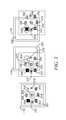
- FIG. 3illustrates the display device of the mobile unit of FIG. 1 for maintaining a view from a translation in accordance with some embodiments.
- FIG. 4illustrates a flowchart of a method for performing a functionality as a function of a movement of the mobile unit in accordance with some embodiments.
- the present inventiondescribes a device and method for performing a predefined functionality.
- the methodcomprises generating first image data indicative of a first view shown on a display device of a mobile unit (MU), the first view including a plurality of selectable elements, each selectable element configured to execute a predefined functionality, the first image data including first position data and first orientation data for each of the selectable elements; determining movement data indicative of a movement of the display device relative to a user of the MU; generating second image data indicative of a second view shown on the display device as a function of the first image data and the movement data, the second view including at least one of the selectable elements, the second image data including second position data and second orientation data for each of the at least one of the selectable elements, the second position data and the second orientation data being the same as the first position data and the first orientation data, respectively, relative to the user; selecting one of the at least one of the selectable elements of the second view as a function of the second position data and the second orientation data; and executing the predefined functionality corresponding
- the exemplary embodimentsmay be further understood with reference to the following description and the appended drawings, wherein like elements are referred to with the same reference numerals.
- the exemplary embodimentsdescribe a device and method for performing a functionality as a function of a movement of a MU that changes a view of a display device. Specifically, the movement of the MU updates the view of the display device to a moved view in which a selected or predetermined functionality is executed or application is launched.
- the functionality, the movement, the view, the moved view, the display device, and a related methodwill be discussed in further detail below.
- FIG. 1is a MU 100 including a plurality of components for performing a functionality as a function of a movement of the MU 100 that changes a view in accordance with an exemplary embodiment of the present invention.
- the MU 100may be any portable device such as a mobile phone, a personal digital assistant, a smartphone, a tablet, a laptop, a barcode reader, etc. Accordingly, the MU 100 may be a handheld device in which the user is capable of moving the MU 100 .
- the movement of the MU 100may be a rotational movement or a translational movement.
- the MU 100may include a processor 105 , a memory arrangement 110 , a display device 115 , an input/output (I/O) device 120 , a transceiver 125 , and other components 130 such as a portable power supply (e.g., battery).
- a portable power supplye.g., battery
- the processor 105may provide conventional functionalities for the MU 100 .
- the MU 100may include a plurality of applications that are executed on the processor 105 such as an application including a web browser when connected to a communication network via the transceiver 125 .
- the memory 110may also provide conventional functionalities for the MU 100 .
- the memory 110may store data related to operations performed by the processor 105 .
- the processor 105may provide a feature that allows the user to maintain an orientation and a position of a view even when the user performs a movement on the MU 100 . Accordingly, the memory 110 may store an initial view for an updated view to be shown.
- the transceiver 125may be any conventional component configured to transmit and/or receive data. The transceiver 125 may therefore enable communication with other electronic devices directly or indirectly through a network.
- the display device 115may be any component configured to show data to a user.
- the display device 115may be, for example, a liquid crystal display (LCD) to conform to the size of the electronic device 100 .
- the I/O device 120may be any component configured to receive an input from the user.
- the I/O device 120may be a keypad (e.g., alphanumeric keypad, numeric keypad, etc.).
- the I/O device 120may also be a touch sensing pad for a user to enter inputs manually with a finger(s) or a stylus.
- the display device 115may also incorporate the I/O device 120 , particularly when the I/O device 120 is a touch sensing pad including an area in which the user may enter inputs.
- the I/O device 120may be a transparent touch sensor placed on top of the display 115 that enables a user to enter inputs.
- the display device 115may be configured to maintain an orientation and a position of selectable elements such as icons in a view thereon even subsequent to the user moving the MU 100 in a rotational manner and/or a translational manner.
- the processor 105may capture an image of the view on the display device 115 and store the image data on the memory 110 .
- the image datamay be predetermined. That is, the image data may have fixed dimensions, in particular dimensions which are larger than the dimensions of the display device 115 .
- the display device 115may show a portion of the image data thereon.
- the processor 105may determine the portions of the image data to be shown on the display device 115 .
- the image datamay be dynamic. That is, the image data shown on the display device 115 may be updated upon the MU 100 being moved in a rotational or a translational manner.
- the processor 105may therefore determine the portions of the image data that should no longer be shown on the display device 115 while also determining further portions of the image data that should be shown on the display device 115 .
- the orientation of the elements in the image or the entire image shown on the display device 115may be maintained. That is, the image may remain in a fixed orientation with respect to the user even after the MU 100 is rotated. Furthermore, the position of the elements in the image or the entire image shown on the display device 115 may be maintained.
- the relative position of points in the imagemay remain fixed with respect to the user even after the MU is translated. Accordingly, the portions of the image remaining to be shown on the display device 115 after the MU 100 undergoes a translational movement remains a fixed distance from the user.
- the processor 105may determine how to maintain the image on the display device 115 using a variety of factors.
- the orientation and relative movement with respect to the user of the MU 100may be determined. These factors may be based upon, for example, the ground (e.g., using an accelerometer), the user (e.g., using a front facing camera or imager), a proximity sensor, or other external physical feature (e.g., also using a camera or imager).
- the other components 130may include a sensor such as a movement sensor (e.g., accelerometer), an image sensor (e.g., camera), etc.
- the orientation of the MU 100may also be used for determining how to show the image data on the display device 115 .
- the MU 100may be rotated in a variety of manners (e.g., pitch, roll, yaw).
- the processor 105may determine the type of rotational movement to determine the image data to be shown.
- the position of the MU 100may further be used for determining how to show the image data on the display device 115 .
- the MU 100may be translated in a variety of manners (e.g., up, down, left, right).
- the processor 105may be configured to adjust the presentation of the image data on the display device 115 using any combination of the above noted factors.
- the features of the exemplary embodiments of the present inventionmay be manually activated or deactivated. That is, the user may allow the features to be used or not.
- the usermay launch a user interface for settings of the MU 100 .
- the user interfacemay include an option to allow the user to activate the features.
- the display device 115may be configured according to the exemplary embodiments of the present invention.
- FIG. 2illustrates the display device 115 of the MU 100 of FIG. 1 for maintaining a view from a rotation in accordance with some embodiments.
- the image data 200 shown on the display device 115may represent an original view. That is, the icons on the image data 200 may be shown in a standard portrait mode (e.g., length greater than width). The dimensions of the original view of the image data 200 may correspond to the dimensions of the display device 115 .
- the icons shown on the image data 200may also be oriented in a manner relative to the user (e.g., right side up).
- the user of the MU 100may choose to rotate the MU 100 . For example, the user may choose to rotate the MU 100 30° counter-clockwise.
- the image data 205 shown on the display device 115may correspond to such a rotational movement.
- an orientation of the image datamay be maintained. That is, the orientation of the image data 200 and the image data 205 are the same. Therefore, the icons shown in the image data 200 may be constant when being updated to the image data 205 after a 30° counter-clockwise rotational movement is performed on the MU 100 . Thus, the icons remain in the same orientation relative to the user as was the case in image data 200 .
- the processor 105may determine that portions of the image data 200 are to be removed for this updated view (e.g., top right corner and bottom left corner) while further portions are required to be shown in the image data 205 (e.g., top left corner and bottom right corner).
- portions of the image data 200are to be removed for this updated view (e.g., top right corner and bottom left corner) while further portions are required to be shown in the image data 205 (e.g., top left corner and bottom right corner).
- the image data 210may be shown on the display device 115 .
- the locations and orientations of the iconsmay remain constant.
- Image data 215 - 240illustrates a further example of the orientation and location of the icons remaining constant when the MU 100 is rotated 180° in a counter-clockwise manner.
- the MU 100may be oriented so that a handle of the housing extends towards the left (e.g., 0° position). Accordingly, the image data 215 may be shown in a standard landscape setting.
- the MU 100may be rotated 45°. In this rotated position, as discussed above, the orientation of the view of the image data 220 remains constant relative to the image data 215 .
- image data 225the MU 100 may be rotated 90°. Thus, the image data 225 may be shown in a standard portrait setting.
- the MU 100may be rotated 100°; in image data 235 , the MU 100 may be rotated 135°; and in image data 240 , the MU 100 may be rotated 180°. In each subsequent rotational move, the view of the image data 230 - 240 may be maintained so that the orientation and position are constant, particularly the icons being in a constant view relative to the user.
- FIG. 3illustrates the display device of the mobile unit of FIG. 1 for maintaining a view from a translation in accordance with some embodiments.
- the image data 300 shown on the display device 115may represent an original view. That is, the icons on the image data 300 may again be shown in a standard portrait mode (e.g., length greater than width).
- the dimensions of the original view of the image data 300may correspond to the dimensions of the display device 115 .
- the image data 300may have greater dimensions than the dimensions of the display device 115 in which case the processor 105 is configured to store the entire image data 300 or adjust accordingly in a dynamic manner.
- the icons shown on the image data 300may also be oriented in a manner relative to the user (e.g., right side up).
- the user of the MU 100may choose to move the MU 100 translationally.
- the usermay choose to move the MU 100 up, down, left, and/or right.
- the image data 320 shown on the display device 115may correspond to an up and right translational movement.
- a position of the image datamay be maintained. That is, the position of the image data 300 and the image data 330 are the same. Therefore, the icons shown in the image data 300 may be constant when being updated to the image data 320 after a translation up and to the right is performed on the MU 100 . Thus, the icons remain in the same position relative to the user as was the case in image data 300 .
- the processor 105may determine that portions of the image data 300 are to be removed for this updated view (e.g., left side and bottom side) while further portions are required to be shown in the image data 320 (e.g., top side and right side). Furthermore, as the icons remain in the same position, some of the icons may be removed from the view. As shown in image data 300 , all the icons 302 - 318 may be shown. However, in image data 320 , the icons 308 , 310 , and 312 may be removed as the MU 100 has been moved enough to place these icons outside the viewing of the display device 115 .
- the icon 314may be partially shown as the MU 100 has been moved in a manner that the top portion of the icon 314 is still visible within the display device 115 .
- the image data 325may be shown on the display device 115 .
- the locations and orientations of the iconsmay remain constant.
- the icons 304 , 316 , and 318may be removed from the view of the display device 115 while the icon 314 again partially remains within the view of the display device 115 .
- the image data shown on the display device 115may be updated in a dynamic manner. That is, when the MU 100 is moved translationally, rotationally, or both, the processor 105 may continuously update the image data shown on the display device 115 . Accordingly, if the display device 115 is moved from a first position to a second position, the image data is continuously shown with the elements therein maintaining the orientation and position throughout the movement from the first position to the second position.
- the movement of the MU 100 and the features for maintaining the position and orientation of the view on the display devicemay further be used to activate a functionality or launch an application.
- the icons 304 - 318may be selected to launch a corresponding application or activate a functionality.
- the icon 302may represent a home or central icon.
- the home icon 302may be, for example, a location within the image data 300 when no action is to be taken or the operating system installed on the MU 100 is to go “back” or return to a home state.
- the MU 100may be disposed in a position so that the icon 302 is selected.
- the icon 304may be selected.
- the icon 304 ′results in which the icon may be enlarged and highlighted around the icon. That is, the icon 304 ′ may be updated with visual features indicative of the selection. Further visual features such as a change in color may also be used.
- the previously selected icon 302 in image data 300may be deselected in which case the icon 302 ′ results that is resized to an original size (e.g., same size as other non-selected icons).
- the icon 308may be selected.
- the icon 308 ′may result that is enlarged and highlighted.
- the processor 105may be configured to automatically launch a corresponding application or perform a corresponding functionality. This action may be performed in a variety of ways. In a first example, the processor 105 may be configured to wait a predetermined amount of time (e.g., 2 seconds) so that when the icon is continuously selected, the processor 105 determines that the corresponding action of the icon is to be performed. In a second example, upon the icon being selected, the user may manually provide an input on the display device 115 (e.g., I/O device 120 incorporated for a touch screen) that selects the icon to perform the corresponding action.
- a predetermined amount of timee.g. 2 seconds
- the MU 100may further be configured to incorporate other movements for the performing of a functionality. As discussed above, the rotational movements are not restricted to a turn within a common plane (e.g., yaw).
- the MU 100may also be rotated with a roll or a pitch.
- the user of the MU 100may perform a pitch forward to change a selection of the icon. For example, with regard to image data 300 , when a pitch forward is performed, the processor 105 may receive this movement input data and move the selection from the icon 302 to the icon 306 . In such a scenario, the icon 306 may be selected, highlighted, and enlarged while the icon 302 is deselected and resized.
- the image data 300may remain constant during this pitch rotational movement. That is, the image data 300 may only be updated when a yaw rotational movement or a translational movement is performed.
- the processor 105may update the image data 300 for additional movements. For example, with a pitch rotational movement, the processor 105 may generate a perspective view so that the image data shown on the display device 115 is maintained with respect to the user. Specifically, with a pitch forward rotational movement, the processor 105 may resize the image data 300 so that an upper portion is widened and zoomed out while a bottom portion is shortened and zoomed in. In this manner, the view of the image data may be substantially the same prior to and after the pitch forward rotational movement.
- non-visual indicatorsmay also be utilized alone or in combination with the visual indicators.
- audio datamay be played on an audio output component of the MU 100 .
- the home icone.g., icon 302
- a prerecorded “home” tonemay be played on the audio output component such as saying the word “home” or a predetermined sound indicative of the home icon.
- a prerecorded tonemay be played on the audio output component such as saying the word “barcode scan”or a predetermined sound indicative of the barcode scan icon.
- the audio datamay be played individually or in combination with the visual indicator as discussed above.
- an iconmay be selected on the image data to provide haptic feedback.
- a predetermined haptic outputmay be performed by the MU 100 .
- the MU 100may include a vibration generating component that generates a vibration that is indicative of the home icon (e.g., continuous vibration for a predetermined amount of time).
- the vibration generating componentmay generate a different type of haptic feedback (e.g., predetermined number of vibrations spaced apart from one another).
- the exemplary embodiments of the present inventionmay incorporate haptic feedback individually, in combination with other non-visual indicators, in combination with the visual indicators as discussed above, or any combination thereof. Accordingly, the types of visual indicators and the types of non-visual indicators may be combined in any manner to indicate to the user the selection/deselection of a particular icon or functionality.
- FIG. 4illustrates a flowchart of a method 400 for performing a functionality as a function of a movement of the mobile unit in accordance with some embodiments.
- the MU 100may be configured to maintain a position and orientation of elements shown on a view of a display device after a movement of the MU 100 as well as perform a functionality from the movement.
- the method 400will be described with reference to the MU 100 of FIG. 1 and the types of movements shown in FIGS. 2 and 3 .
- image datais shown on the display device 115 .
- the processor 105is configured to run at least one application such as an operating system.
- the operating systemmay have a home screen in which a plurality of icons or selectable elements are shown.
- the icons 302 - 318may be shown.
- the movemente.g., roll, pitch, yaw
- a translational movemente.g, up, down, left, right
- step 415the image data shown on the display device 115 is updated.
- the processor 105may determine the updated, moved view on the display device 115 .
- the processor 105may again determine the updated, moved view on the display device 115 .
- the processor 105may determine the updated, moved view on the display device 115 .
- step 420the processor 105 determines if a functionality is selected. If no functionality is selected, the method 400 returns to step 415 where the updated, moved image is continued to be shown on the display device 115 . However, if a predefined functionality is selected, the method 400 continues to step 425 . As discussed above, the image data 300 may select the icon 302 that corresponds to a predefined functionality. Subsequently, if the display device 115 is moved in a translational manner such as up and to the right, a selection functionality may be triggered so that the icon 304 may be selected. Thus, in step 425 , the defined functionality is performed. As discussed above, the functionality may be performed in a variety of manners. For example, the processor 105 may automatically activate and perform the selected predefined functionality. In another example, the user may manually enter an input to perform the selected functionality.
- the exemplary embodiments of the present inventionprovide a device and method for performing a functionality as a function of a movement of a MU that changes a view of a display device.
- the movement of the MU and the display devicemay be with regard to a rotational movement and/or a translational movement.
- the processor of the MUis configured to update the view on the display device as a function of the performed movement.
- the processor of the MUmay be configured to perform a functionality as a function of the performed movement. For example, a selection functionality may be triggered so that an icon corresponding to the selected functionality may be altered such as changing a size or display of the icon.
- aincludes . . . a”, “contains . . . a” does not, without more constraints, preclude the existence of additional identical elements in the process, method, article, or apparatus that comprises, has, includes, contains the element.
- the terms “a” and “an”are defined as one or more unless explicitly stated otherwise herein.
- the terms “substantially”, “essentially”, “approximately”, “about” or any other version thereof,are defined as being close to as understood by one of ordinary skill in the art, and in one non-limiting embodiment the term is defined to be within 10%, in another embodiment within 5%, in another embodiment within 1% and in another embodiment within 0.5%.
- the term “coupled” as used hereinis defined as connected, although not necessarily directly and not necessarily mechanically.
- a device or structure that is “configured” in a certain wayis configured in at least that way, but may also be configured in ways that are not listed.
- processorssuch as microprocessors, digital signal processors, customized processors and field programmable gate arrays (FPGAs) and unique stored program instructions (including both software and firmware) that control the one or more processors to implement, in conjunction with certain non-processor circuits, some, most, or all of the functions of the method and/or apparatus described herein.
- processorsor “processing devices” such as microprocessors, digital signal processors, customized processors and field programmable gate arrays (FPGAs) and unique stored program instructions (including both software and firmware) that control the one or more processors to implement, in conjunction with certain non-processor circuits, some, most, or all of the functions of the method and/or apparatus described herein.
- FPGAsfield programmable gate arrays
- unique stored program instructionsincluding both software and firmware
- an embodimentcan be implemented as a computer-readable storage medium having computer readable code stored thereon for programming a computer (e.g., comprising a processor) to perform a method as described and claimed herein.
- Examples of such computer-readable storage mediumsinclude, but are not limited to, a hard disk, a CD-ROM, an optical storage device, a magnetic storage device, a ROM (Read Only Memory), a PROM (Programmable Read Only Memory), an EPROM (Erasable Programmable Read Only Memory), an EEPROM (Electrically Erasable Programmable Read Only Memory) and a Flash memory.
Landscapes
- Engineering & Computer Science (AREA)
- Theoretical Computer Science (AREA)
- General Engineering & Computer Science (AREA)
- Human Computer Interaction (AREA)
- Physics & Mathematics (AREA)
- General Physics & Mathematics (AREA)
- Computer Hardware Design (AREA)
- User Interface Of Digital Computer (AREA)
Abstract
Description
Claims (19)
Priority Applications (4)
| Application Number | Priority Date | Filing Date | Title |
|---|---|---|---|
| US13/684,658US9791896B2 (en) | 2012-07-13 | 2012-11-26 | Device and method for performing a functionality |
| DE112013003511.1TDE112013003511B4 (en) | 2012-07-13 | 2013-07-10 | Device and method for executing a function |
| GB1500202.5AGB2518564B (en) | 2012-07-13 | 2013-07-10 | Device and method for performing a functionality |
| PCT/US2013/049945WO2014011785A1 (en) | 2012-07-13 | 2013-07-10 | Device and method for performing a functionality |
Applications Claiming Priority (2)
| Application Number | Priority Date | Filing Date | Title |
|---|---|---|---|
| US201261741163P | 2012-07-13 | 2012-07-13 | |
| US13/684,658US9791896B2 (en) | 2012-07-13 | 2012-11-26 | Device and method for performing a functionality |
Publications (2)
| Publication Number | Publication Date |
|---|---|
| US20140145925A1 US20140145925A1 (en) | 2014-05-29 |
| US9791896B2true US9791896B2 (en) | 2017-10-17 |
Family
ID=48874523
Family Applications (1)
| Application Number | Title | Priority Date | Filing Date |
|---|---|---|---|
| US13/684,658Active2032-12-11US9791896B2 (en) | 2012-07-13 | 2012-11-26 | Device and method for performing a functionality |
Country Status (4)
| Country | Link |
|---|---|
| US (1) | US9791896B2 (en) |
| DE (1) | DE112013003511B4 (en) |
| GB (1) | GB2518564B (en) |
| WO (1) | WO2014011785A1 (en) |
Families Citing this family (3)
| Publication number | Priority date | Publication date | Assignee | Title |
|---|---|---|---|---|
| US9202095B2 (en) | 2012-07-13 | 2015-12-01 | Symbol Technologies, Llc | Pistol grip adapter for mobile device |
| US9697393B2 (en) | 2015-11-20 | 2017-07-04 | Symbol Technologies, Llc | Methods and systems for adjusting mobile-device operating parameters based on housing-support type |
| US10509473B2 (en)* | 2017-09-21 | 2019-12-17 | Paypal, Inc. | Providing haptic feedback on a screen |
Citations (79)
| Publication number | Priority date | Publication date | Assignee | Title |
|---|---|---|---|---|
| US4097133A (en) | 1976-03-12 | 1978-06-27 | Agfa-Gevaert Ag | Cinematographic camera |
| US4282425A (en) | 1979-07-25 | 1981-08-04 | Norand Corporation | Instant portable bar code reader |
| US5035181A (en) | 1985-01-22 | 1991-07-30 | The United States Of America As Represented By The Secretary Of The Navy | Thermosensitive pop-out device |
| US5204531A (en) | 1992-02-14 | 1993-04-20 | Digital Instruments, Inc. | Method of adjusting the size of the area scanned by a scanning probe |
| WO1993014472A1 (en) | 1992-01-16 | 1993-07-22 | Metrologic Instruments, Inc. | Hands-free body mounted laser scanner and method of use |
| US5250790A (en) | 1988-05-11 | 1993-10-05 | Symbol Technologies, Inc. | Hand-mounted scanner with automatic manual initiation of reading indicia |
| US5340972A (en) | 1991-05-13 | 1994-08-23 | Symbol Technologies, Inc. | Hands-free bar code scanner with finger activated optical control |
| GB2299394A (en) | 1995-03-31 | 1996-10-02 | Frazer Concepts Ltd | Computer input devices |
| US5770848A (en) | 1994-11-28 | 1998-06-23 | Hitachi, Ltd. | Apparatus and method for treating a commodity by automatically recognizing a barcode attached to a conveyed commodity by scanner |
| US5801918A (en) | 1996-07-12 | 1998-09-01 | Hand Held Products, Inc. | Ergonomic housing for a micro computer |
| US5905248A (en) | 1990-09-11 | 1999-05-18 | Metrologic Instruments, Inc. | System and method for carrying out information-related transactions using web documents embodying transaction enabling applets automatically launched and executed in response to reading URL-encoded symbols pointing thereto |
| US5970184A (en) | 1990-11-20 | 1999-10-19 | Fujitsu Limited | Laser beam generation control system for optical bar code scanner |
| US6085981A (en) | 1990-09-11 | 2000-07-11 | Metrologic Instruments, Inc. | Automatic hand-mounted bar code symbol laser scanner |
| US6115025A (en) | 1997-09-30 | 2000-09-05 | Silicon Graphics, Inc. | System for maintaining orientation of a user interface as a display changes orientation |
| US6184654B1 (en) | 1998-07-28 | 2001-02-06 | Double-Time Battery Corporation | Wearable docking-holster system, with energy management, to support portable electronic devices |
| WO2001027735A1 (en) | 1999-10-12 | 2001-04-19 | Myorigo Oy | Operation method of user interface of hand-held device |
| GB2358336A (en) | 1999-11-03 | 2001-07-18 | Motorola Inc | Selecting alphanumeric characters or menu options by movement of the display device |
| US6286760B1 (en) | 1994-08-17 | 2001-09-11 | Metrologic Instruments, Inc. | Automatic hand-supportable laser projection scanner for omni-directional reading of bar code symbols within a narrowly confined scanning volume |
| US20010048423A1 (en)* | 1996-08-05 | 2001-12-06 | Junichi Rekimoto | Information processing device and method |
| US6421234B1 (en) | 2000-10-10 | 2002-07-16 | Juniper Systems, Inc. | Handheld electronics device having ergonomic features |
| EP1225501A2 (en) | 2001-01-23 | 2002-07-24 | Symbol Technologies, Inc. | Adapter unit having a handle grip for a personal digital assistant |
| US20020140668A1 (en) | 2001-04-03 | 2002-10-03 | Crawford Peter James | Thumb actuated x-y input device |
| US20020140666A1 (en)* | 2001-03-29 | 2002-10-03 | Bradski Gary R. | Intuitive mobile device interface to virtual spaces |
| US20020165436A1 (en) | 2000-12-05 | 2002-11-07 | Paul Schluter | Medical device having a combination data reader and infrared data transceiver and method of using same |
| US6502754B1 (en) | 1999-03-01 | 2003-01-07 | Symbol Technologies, Inc. | Data acquisition device |
| US20030020707A1 (en)* | 2001-06-27 | 2003-01-30 | Kangas Kari J. | User interface |
| US6518952B1 (en) | 1996-07-08 | 2003-02-11 | Thomas Leiper | System for manipulation and display of medical images |
| US6575369B1 (en) | 1992-06-12 | 2003-06-10 | Metrologic Instruments, Inc. | Automatic optical projection scanner with improved activation controlling mechanism |
| US6607134B1 (en) | 1997-07-17 | 2003-08-19 | Symbol Technologies, Inc. | Finger-mounted readers with low power radio frequency communications |
| US20030179178A1 (en) | 2003-04-23 | 2003-09-25 | Brian Zargham | Mobile Text Entry Device |
| US6726070B2 (en) | 2002-05-20 | 2004-04-27 | Robert Lautner | Ergonomic input-device holder |
| US6754069B2 (en) | 2001-02-07 | 2004-06-22 | Matsushita Electric Industrial Co., Ltd. | Portable terminal wearable on forearm |
| GB2396728A (en) | 2002-12-23 | 2004-06-30 | Motorola Inc | Target reading system with a separate adjustable illumination source |
| WO2004066615A1 (en) | 2003-01-22 | 2004-08-05 | Nokia Corporation | Image control |
| US20050001036A1 (en) | 1997-09-16 | 2005-01-06 | Metrologic Instruments, Inc. | Bar code symbol reading system employing electronically-controlled raster-type laser scanner for reading bar code symbols during hands-on and hands-free modes of operation |
| US6853293B2 (en) | 1993-05-28 | 2005-02-08 | Symbol Technologies, Inc. | Wearable communication system |
| US20060197753A1 (en) | 2005-03-04 | 2006-09-07 | Hotelling Steven P | Multi-functional hand-held device |
| US7157705B2 (en) | 2001-05-07 | 2007-01-02 | Flir Systems Ab | Handheld infrared camera |
| US7191947B2 (en) | 2004-07-23 | 2007-03-20 | Symbol Technologies, Inc. | Point-of-transaction workstation for electro-optical reading one-dimensional indicia, including image capture of two-dimensional targets |
| US20070067745A1 (en) | 2005-08-22 | 2007-03-22 | Joon-Hyuk Choi | Autonomous handheld device having a drawing tool |
| USD540838S1 (en) | 2005-01-13 | 2007-04-17 | Flir Systems Ab | Camera |
| WO2007061498A2 (en) | 2005-11-14 | 2007-05-31 | Symbol Technologies, Inc. | Grip security arrangement |
| US7250603B1 (en) | 2006-03-24 | 2007-07-31 | Draeger Safety, Inc. | Crawling handle for thermal imaging camera |
| US20080078839A1 (en) | 2006-09-28 | 2008-04-03 | Edward Barkan | Electro-optical reader with object sensor |
| US20080128499A1 (en) | 2006-12-05 | 2008-06-05 | Intermec Ip Corp. | Programmable trigger handle for handheld devices |
| US20080128492A1 (en) | 2006-12-01 | 2008-06-05 | Prime Technology Llc | Item having a data tag |
| US20080128512A1 (en) | 1998-12-03 | 2008-06-05 | Metrologic Instruments, Inc. | Wireless hand-supportable code symbol reading system with automatic communication range dependent control |
| US7389933B2 (en) | 2006-10-13 | 2008-06-24 | Symbol Technologies, Inc. | Triggerless electro-optical reader |
| US20080163504A1 (en) | 2007-01-05 | 2008-07-10 | Smith John E | Apparatus and methods for locating and identifying remote objects |
| US20090033633A1 (en) | 2007-07-31 | 2009-02-05 | Palo Alto Research Center Incorporated | User interface for a context-aware leisure-activity recommendation system |
| US20090039162A1 (en) | 2007-08-10 | 2009-02-12 | Leeway Yen | Tag reader and the tag |
| US7490776B2 (en) | 2005-11-16 | 2009-02-17 | Intermec Scanner Technology Center | Sensor control of an aiming beam of an automatic data collection device, such as a barcode reader |
| US20090102925A1 (en) | 2007-10-17 | 2009-04-23 | Fluke Corporation | Ergonomic configurations for thermal imaging cameras |
| US7562824B2 (en) | 2003-07-23 | 2009-07-21 | Symbol Technologies, Inc | Mobile terminal with ergonomic housing |
| US7566009B2 (en) | 2003-04-07 | 2009-07-28 | Silverbrook Research Pty Ltd | Reading device having a harness |
| US20090262074A1 (en)* | 2007-01-05 | 2009-10-22 | Invensense Inc. | Controlling and accessing content using motion processing on mobile devices |
| US20090307634A1 (en) | 2008-06-07 | 2009-12-10 | Nokia Corporation | User Interface, Device and Method for Displaying a Stable Screen View |
| US20100026498A1 (en) | 2008-07-29 | 2010-02-04 | David Bellows | Method and System for Adapting a Mobile Computing Device with an RFID Antenna |
| US20100037184A1 (en)* | 2008-08-08 | 2010-02-11 | Chi Mei Communication Systems, Inc. | Portable electronic device and method for selecting menu items |
| US20100046577A1 (en) | 2008-08-21 | 2010-02-25 | Fluke Corporation | Thermal instrument engine |
| US7679604B2 (en)* | 2001-03-29 | 2010-03-16 | Uhlik Christopher R | Method and apparatus for controlling a computer system |
| US7746511B2 (en) | 2004-04-23 | 2010-06-29 | Symbol Technologies, Inc. | Scan head rotation at different optimum angles |
| US7748632B2 (en) | 2006-07-25 | 2010-07-06 | Hand Held Products, Inc. | Portable data terminal and battery therefor |
| US20100171021A1 (en) | 2009-01-06 | 2010-07-08 | Mark Smith | Holder systems for mobile devices |
| US7764488B2 (en) | 2007-04-23 | 2010-07-27 | Symbol Technologies, Inc. | Wearable component with a memory arrangement |
| US20100277506A1 (en) | 2009-04-30 | 2010-11-04 | Shenzhen Futaihong Precision Industry Co., Ltd. | System and method for adjusting user interface of electronic device |
| US20100328344A1 (en)* | 2009-06-25 | 2010-12-30 | Nokia Corporation | Method and apparatus for an augmented reality user interface |
| US7867019B1 (en) | 2009-07-17 | 2011-01-11 | Fluke Corporation | Thermal imaging device with a battery pack with a shock absorber |
| US7886377B2 (en) | 2006-10-13 | 2011-02-15 | Hill-Rom Services, Inc. | Push handle with rotatable user interface |
| US20110075339A1 (en) | 2001-04-27 | 2011-03-31 | Palm, Inc. | Keyboard sled with rotating screen |
| US20110164056A1 (en) | 2010-01-06 | 2011-07-07 | Bas Ording | Device, Method, and Graphical User Interface with Grid Transformations During Device Rotation |
| US20110246336A1 (en) | 1993-10-13 | 2011-10-06 | Dataquill Limited | Data entry systems |
| US20110290889A1 (en) | 2010-05-28 | 2011-12-01 | Datalogic Scanning, Inc. | Data reader with multiple modes of operation |
| US20120032982A1 (en)* | 2007-06-29 | 2012-02-09 | Microsoft Corporation | Manipulation of Graphical Objects |
| USD658222S1 (en) | 2011-03-23 | 2012-04-24 | Fluke Corporation | Thermal imager |
| USD665440S1 (en) | 2010-11-03 | 2012-08-14 | Flir Systems Ab | Infrared camera |
| US8255836B1 (en) | 2011-03-30 | 2012-08-28 | Google Inc. | Hover-over gesturing on mobile devices |
| US8717283B1 (en)* | 2008-11-25 | 2014-05-06 | Sprint Communications Company L.P. | Utilizing motion of a device to manipulate a display screen feature |
| US9035878B1 (en)* | 2012-02-29 | 2015-05-19 | Google Inc. | Input system |
- 2012
- 2012-11-26USUS13/684,658patent/US9791896B2/enactiveActive
- 2013
- 2013-07-10WOPCT/US2013/049945patent/WO2014011785A1/enactiveApplication Filing
- 2013-07-10GBGB1500202.5Apatent/GB2518564B/enactiveActive
- 2013-07-10DEDE112013003511.1Tpatent/DE112013003511B4/enactiveActive
Patent Citations (84)
| Publication number | Priority date | Publication date | Assignee | Title |
|---|---|---|---|---|
| US4097133A (en) | 1976-03-12 | 1978-06-27 | Agfa-Gevaert Ag | Cinematographic camera |
| US4282425A (en) | 1979-07-25 | 1981-08-04 | Norand Corporation | Instant portable bar code reader |
| US5035181A (en) | 1985-01-22 | 1991-07-30 | The United States Of America As Represented By The Secretary Of The Navy | Thermosensitive pop-out device |
| US5250790A (en) | 1988-05-11 | 1993-10-05 | Symbol Technologies, Inc. | Hand-mounted scanner with automatic manual initiation of reading indicia |
| US5905248A (en) | 1990-09-11 | 1999-05-18 | Metrologic Instruments, Inc. | System and method for carrying out information-related transactions using web documents embodying transaction enabling applets automatically launched and executed in response to reading URL-encoded symbols pointing thereto |
| US6223987B1 (en) | 1990-09-11 | 2001-05-01 | Metrologic Instruments, Inc. | Body-wearable automatic laser scanner |
| US6648229B1 (en) | 1990-09-11 | 2003-11-18 | Metrologic Instruments, Inc. | Optical scanner with mounting/conveying mechanism and system control circuitry |
| US6085981A (en) | 1990-09-11 | 2000-07-11 | Metrologic Instruments, Inc. | Automatic hand-mounted bar code symbol laser scanner |
| US5970184A (en) | 1990-11-20 | 1999-10-19 | Fujitsu Limited | Laser beam generation control system for optical bar code scanner |
| US5340972A (en) | 1991-05-13 | 1994-08-23 | Symbol Technologies, Inc. | Hands-free bar code scanner with finger activated optical control |
| WO1993014472A1 (en) | 1992-01-16 | 1993-07-22 | Metrologic Instruments, Inc. | Hands-free body mounted laser scanner and method of use |
| US5204531A (en) | 1992-02-14 | 1993-04-20 | Digital Instruments, Inc. | Method of adjusting the size of the area scanned by a scanning probe |
| US6575369B1 (en) | 1992-06-12 | 2003-06-10 | Metrologic Instruments, Inc. | Automatic optical projection scanner with improved activation controlling mechanism |
| US6853293B2 (en) | 1993-05-28 | 2005-02-08 | Symbol Technologies, Inc. | Wearable communication system |
| US20110246336A1 (en) | 1993-10-13 | 2011-10-06 | Dataquill Limited | Data entry systems |
| US6286760B1 (en) | 1994-08-17 | 2001-09-11 | Metrologic Instruments, Inc. | Automatic hand-supportable laser projection scanner for omni-directional reading of bar code symbols within a narrowly confined scanning volume |
| US5770848A (en) | 1994-11-28 | 1998-06-23 | Hitachi, Ltd. | Apparatus and method for treating a commodity by automatically recognizing a barcode attached to a conveyed commodity by scanner |
| GB2299394A (en) | 1995-03-31 | 1996-10-02 | Frazer Concepts Ltd | Computer input devices |
| US6518952B1 (en) | 1996-07-08 | 2003-02-11 | Thomas Leiper | System for manipulation and display of medical images |
| US5801918A (en) | 1996-07-12 | 1998-09-01 | Hand Held Products, Inc. | Ergonomic housing for a micro computer |
| US20010048423A1 (en)* | 1996-08-05 | 2001-12-06 | Junichi Rekimoto | Information processing device and method |
| US6607134B1 (en) | 1997-07-17 | 2003-08-19 | Symbol Technologies, Inc. | Finger-mounted readers with low power radio frequency communications |
| US20050001036A1 (en) | 1997-09-16 | 2005-01-06 | Metrologic Instruments, Inc. | Bar code symbol reading system employing electronically-controlled raster-type laser scanner for reading bar code symbols during hands-on and hands-free modes of operation |
| US6115025A (en) | 1997-09-30 | 2000-09-05 | Silicon Graphics, Inc. | System for maintaining orientation of a user interface as a display changes orientation |
| US6184654B1 (en) | 1998-07-28 | 2001-02-06 | Double-Time Battery Corporation | Wearable docking-holster system, with energy management, to support portable electronic devices |
| US20080128512A1 (en) | 1998-12-03 | 2008-06-05 | Metrologic Instruments, Inc. | Wireless hand-supportable code symbol reading system with automatic communication range dependent control |
| US6502754B1 (en) | 1999-03-01 | 2003-01-07 | Symbol Technologies, Inc. | Data acquisition device |
| WO2001027735A1 (en) | 1999-10-12 | 2001-04-19 | Myorigo Oy | Operation method of user interface of hand-held device |
| GB2358336A (en) | 1999-11-03 | 2001-07-18 | Motorola Inc | Selecting alphanumeric characters or menu options by movement of the display device |
| US6421234B1 (en) | 2000-10-10 | 2002-07-16 | Juniper Systems, Inc. | Handheld electronics device having ergonomic features |
| US20020165436A1 (en) | 2000-12-05 | 2002-11-07 | Paul Schluter | Medical device having a combination data reader and infrared data transceiver and method of using same |
| US7065299B2 (en) | 2000-12-05 | 2006-06-20 | Ge Medical Systems Information Technologies, Inc. | Medical device having a combination data reader and infrared data transceiver and method of using same |
| EP1225501A2 (en) | 2001-01-23 | 2002-07-24 | Symbol Technologies, Inc. | Adapter unit having a handle grip for a personal digital assistant |
| US6754069B2 (en) | 2001-02-07 | 2004-06-22 | Matsushita Electric Industrial Co., Ltd. | Portable terminal wearable on forearm |
| US20020140666A1 (en)* | 2001-03-29 | 2002-10-03 | Bradski Gary R. | Intuitive mobile device interface to virtual spaces |
| US7679604B2 (en)* | 2001-03-29 | 2010-03-16 | Uhlik Christopher R | Method and apparatus for controlling a computer system |
| US20020140668A1 (en) | 2001-04-03 | 2002-10-03 | Crawford Peter James | Thumb actuated x-y input device |
| US20110075339A1 (en) | 2001-04-27 | 2011-03-31 | Palm, Inc. | Keyboard sled with rotating screen |
| US7157705B2 (en) | 2001-05-07 | 2007-01-02 | Flir Systems Ab | Handheld infrared camera |
| US20030020707A1 (en)* | 2001-06-27 | 2003-01-30 | Kangas Kari J. | User interface |
| US6726070B2 (en) | 2002-05-20 | 2004-04-27 | Robert Lautner | Ergonomic input-device holder |
| US20040129903A1 (en) | 2002-12-23 | 2004-07-08 | Menachem Diamantstein | System, method and equipment for reading information on a target |
| GB2396728A (en) | 2002-12-23 | 2004-06-30 | Motorola Inc | Target reading system with a separate adjustable illumination source |
| WO2004066615A1 (en) | 2003-01-22 | 2004-08-05 | Nokia Corporation | Image control |
| US7566009B2 (en) | 2003-04-07 | 2009-07-28 | Silverbrook Research Pty Ltd | Reading device having a harness |
| US20030179178A1 (en) | 2003-04-23 | 2003-09-25 | Brian Zargham | Mobile Text Entry Device |
| US7562824B2 (en) | 2003-07-23 | 2009-07-21 | Symbol Technologies, Inc | Mobile terminal with ergonomic housing |
| US7746511B2 (en) | 2004-04-23 | 2010-06-29 | Symbol Technologies, Inc. | Scan head rotation at different optimum angles |
| US7191947B2 (en) | 2004-07-23 | 2007-03-20 | Symbol Technologies, Inc. | Point-of-transaction workstation for electro-optical reading one-dimensional indicia, including image capture of two-dimensional targets |
| USD540838S1 (en) | 2005-01-13 | 2007-04-17 | Flir Systems Ab | Camera |
| US20060197753A1 (en) | 2005-03-04 | 2006-09-07 | Hotelling Steven P | Multi-functional hand-held device |
| US20070067745A1 (en) | 2005-08-22 | 2007-03-22 | Joon-Hyuk Choi | Autonomous handheld device having a drawing tool |
| WO2007061498A2 (en) | 2005-11-14 | 2007-05-31 | Symbol Technologies, Inc. | Grip security arrangement |
| US7490776B2 (en) | 2005-11-16 | 2009-02-17 | Intermec Scanner Technology Center | Sensor control of an aiming beam of an automatic data collection device, such as a barcode reader |
| US7250603B1 (en) | 2006-03-24 | 2007-07-31 | Draeger Safety, Inc. | Crawling handle for thermal imaging camera |
| US7748632B2 (en) | 2006-07-25 | 2010-07-06 | Hand Held Products, Inc. | Portable data terminal and battery therefor |
| US20080078839A1 (en) | 2006-09-28 | 2008-04-03 | Edward Barkan | Electro-optical reader with object sensor |
| US7886377B2 (en) | 2006-10-13 | 2011-02-15 | Hill-Rom Services, Inc. | Push handle with rotatable user interface |
| US7389933B2 (en) | 2006-10-13 | 2008-06-24 | Symbol Technologies, Inc. | Triggerless electro-optical reader |
| US20080128492A1 (en) | 2006-12-01 | 2008-06-05 | Prime Technology Llc | Item having a data tag |
| US20080128499A1 (en) | 2006-12-05 | 2008-06-05 | Intermec Ip Corp. | Programmable trigger handle for handheld devices |
| US20080163504A1 (en) | 2007-01-05 | 2008-07-10 | Smith John E | Apparatus and methods for locating and identifying remote objects |
| US20090262074A1 (en)* | 2007-01-05 | 2009-10-22 | Invensense Inc. | Controlling and accessing content using motion processing on mobile devices |
| US7764488B2 (en) | 2007-04-23 | 2010-07-27 | Symbol Technologies, Inc. | Wearable component with a memory arrangement |
| US8314817B2 (en)* | 2007-06-29 | 2012-11-20 | Microsoft Corporation | Manipulation of graphical objects |
| US20120032982A1 (en)* | 2007-06-29 | 2012-02-09 | Microsoft Corporation | Manipulation of Graphical Objects |
| US20090033633A1 (en) | 2007-07-31 | 2009-02-05 | Palo Alto Research Center Incorporated | User interface for a context-aware leisure-activity recommendation system |
| US20090039162A1 (en) | 2007-08-10 | 2009-02-12 | Leeway Yen | Tag reader and the tag |
| US20090102925A1 (en) | 2007-10-17 | 2009-04-23 | Fluke Corporation | Ergonomic configurations for thermal imaging cameras |
| US20090307634A1 (en) | 2008-06-07 | 2009-12-10 | Nokia Corporation | User Interface, Device and Method for Displaying a Stable Screen View |
| US20100026498A1 (en) | 2008-07-29 | 2010-02-04 | David Bellows | Method and System for Adapting a Mobile Computing Device with an RFID Antenna |
| US20100037184A1 (en)* | 2008-08-08 | 2010-02-11 | Chi Mei Communication Systems, Inc. | Portable electronic device and method for selecting menu items |
| US20100046577A1 (en) | 2008-08-21 | 2010-02-25 | Fluke Corporation | Thermal instrument engine |
| US8717283B1 (en)* | 2008-11-25 | 2014-05-06 | Sprint Communications Company L.P. | Utilizing motion of a device to manipulate a display screen feature |
| US20100171021A1 (en) | 2009-01-06 | 2010-07-08 | Mark Smith | Holder systems for mobile devices |
| US20100277506A1 (en) | 2009-04-30 | 2010-11-04 | Shenzhen Futaihong Precision Industry Co., Ltd. | System and method for adjusting user interface of electronic device |
| US20100328344A1 (en)* | 2009-06-25 | 2010-12-30 | Nokia Corporation | Method and apparatus for an augmented reality user interface |
| US7867019B1 (en) | 2009-07-17 | 2011-01-11 | Fluke Corporation | Thermal imaging device with a battery pack with a shock absorber |
| US20110164056A1 (en) | 2010-01-06 | 2011-07-07 | Bas Ording | Device, Method, and Graphical User Interface with Grid Transformations During Device Rotation |
| US20110290889A1 (en) | 2010-05-28 | 2011-12-01 | Datalogic Scanning, Inc. | Data reader with multiple modes of operation |
| USD665440S1 (en) | 2010-11-03 | 2012-08-14 | Flir Systems Ab | Infrared camera |
| USD658222S1 (en) | 2011-03-23 | 2012-04-24 | Fluke Corporation | Thermal imager |
| US8255836B1 (en) | 2011-03-30 | 2012-08-28 | Google Inc. | Hover-over gesturing on mobile devices |
| US9035878B1 (en)* | 2012-02-29 | 2015-05-19 | Google Inc. | Input system |
Non-Patent Citations (4)
| Title |
|---|
| International Search Report and Written Opinion dated Oct. 10, 2013 in counterpart PCT application No. PCT/US2013/049945. |
| Leenes R., et al., "Prime white paper," EU Project Prime, Privacy and Identity Management for Europe, Third and Final Version, May 15, 2008, 22 pages. |
| Non Final Office Action dated Aug. 22, 2013 in U.S. Appl. No. 13/685,750, Richard M Martin, filed Nov. 22, 2012. |
| Office action for German Patent Application No. 112013003511.1 dated Aug. 10, 2016. |
Also Published As
| Publication number | Publication date |
|---|---|
| DE112013003511B4 (en) | 2024-10-31 |
| WO2014011785A1 (en) | 2014-01-16 |
| GB2518564B (en) | 2020-12-09 |
| DE112013003511T5 (en) | 2015-05-07 |
| US20140145925A1 (en) | 2014-05-29 |
| GB2518564A (en) | 2015-03-25 |
Similar Documents
| Publication | Publication Date | Title |
|---|---|---|
| EP2960783B1 (en) | Mobile terminal and method for controlling the same | |
| US9524040B2 (en) | Image editing apparatus and method for selecting area of interest | |
| US9766739B2 (en) | Method and apparatus for constructing a home screen in a terminal having a touch screen | |
| US8294682B2 (en) | Displaying system and method thereof | |
| EP2715499B1 (en) | Invisible control | |
| US9836213B2 (en) | Enhanced user interface for pressure sensitive touch screen | |
| US9508322B2 (en) | Text box resizing | |
| US20170010780A1 (en) | Programmable touchscreen zone for mobile devices | |
| CN113748407A (en) | Electronic device and method for displaying split screen providing object | |
| US9030430B2 (en) | Multi-touch navigation mode | |
| KR20170093658A (en) | Electronic device comprising multiple displays and method for controlling thereof | |
| US9152316B2 (en) | Electronic device, controlling method thereof, and non-transitory storage medium | |
| US20150193112A1 (en) | User interface device, user interface method, and program | |
| US20140310653A1 (en) | Displaying history information for application | |
| WO2015017174A1 (en) | Method and apparatus for generating customized menus for accessing application functionality | |
| CA2785016C (en) | Overlay handling | |
| US20160224221A1 (en) | Apparatus for enabling displaced effective input and associated methods | |
| US20150185987A1 (en) | Method, apparatus and computer readable medium for zooming and operating screen frame | |
| KR20140026723A (en) | Method for providing guide in portable device and portable device thereof | |
| US20140380244A1 (en) | Visual table of contents for touch sensitive devices | |
| CN106408289B (en) | A payment page switching method and mobile terminal | |
| KR20170059815A (en) | Rollable mobile terminal | |
| KR20140099588A (en) | Method for editing contents and display device implementing the same | |
| US9791896B2 (en) | Device and method for performing a functionality | |
| WO2016183912A1 (en) | Menu layout arrangement method and apparatus |
Legal Events
| Date | Code | Title | Description |
|---|---|---|---|
| AS | Assignment | Owner name:SYMBOL TECHNOLOGIES, INC., NEW YORK Free format text:ASSIGNMENT OF ASSIGNORS INTEREST;ASSIGNORS:MARTIN, RICHARD M.;CHOI, JAEHO;JENKINS, IAN R.;AND OTHERS;SIGNING DATES FROM 20121114 TO 20121119;REEL/FRAME:029345/0678 | |
| AS | Assignment | Owner name:MORGAN STANLEY SENIOR FUNDING, INC. AS THE COLLATERAL AGENT, MARYLAND Free format text:SECURITY AGREEMENT;ASSIGNORS:ZIH CORP.;LASER BAND, LLC;ZEBRA ENTERPRISE SOLUTIONS CORP.;AND OTHERS;REEL/FRAME:034114/0270 Effective date:20141027 Owner name:MORGAN STANLEY SENIOR FUNDING, INC. AS THE COLLATE Free format text:SECURITY AGREEMENT;ASSIGNORS:ZIH CORP.;LASER BAND, LLC;ZEBRA ENTERPRISE SOLUTIONS CORP.;AND OTHERS;REEL/FRAME:034114/0270 Effective date:20141027 | |
| AS | Assignment | Owner name:SYMBOL TECHNOLOGIES, LLC, NEW YORK Free format text:CHANGE OF NAME;ASSIGNOR:SYMBOL TECHNOLOGIES, INC.;REEL/FRAME:036083/0640 Effective date:20150410 | |
| AS | Assignment | Owner name:SYMBOL TECHNOLOGIES, INC., NEW YORK Free format text:RELEASE BY SECURED PARTY;ASSIGNOR:MORGAN STANLEY SENIOR FUNDING, INC.;REEL/FRAME:036371/0738 Effective date:20150721 | |
| STCF | Information on status: patent grant | Free format text:PATENTED CASE | |
| MAFP | Maintenance fee payment | Free format text:PAYMENT OF MAINTENANCE FEE, 4TH YEAR, LARGE ENTITY (ORIGINAL EVENT CODE: M1551); ENTITY STATUS OF PATENT OWNER: LARGE ENTITY Year of fee payment:4 | |
| MAFP | Maintenance fee payment | Free format text:PAYMENT OF MAINTENANCE FEE, 8TH YEAR, LARGE ENTITY (ORIGINAL EVENT CODE: M1552); ENTITY STATUS OF PATENT OWNER: LARGE ENTITY Year of fee payment:8 |