US9789321B2 - Couplings for implanted leads and external stimulators, and associated systems and methods - Google Patents
Couplings for implanted leads and external stimulators, and associated systems and methodsDownload PDFInfo
- Publication number
- US9789321B2 US9789321B2US14/678,785US201514678785AUS9789321B2US 9789321 B2US9789321 B2US 9789321B2US 201514678785 AUS201514678785 AUS 201514678785AUS 9789321 B2US9789321 B2US 9789321B2
- Authority
- US
- United States
- Prior art keywords
- connector
- stop
- partially
- lead
- contacts
- Prior art date
- Legal status (The legal status is an assumption and is not a legal conclusion. Google has not performed a legal analysis and makes no representation as to the accuracy of the status listed.)
- Active
Links
- 238000000034methodMethods0.000titleabstractdescription22
- 230000008878couplingEffects0.000titleabstractdescription5
- 238000010168coupling processMethods0.000titleabstractdescription5
- 238000005859coupling reactionMethods0.000titleabstractdescription5
- 230000000638stimulationEffects0.000claimsabstractdescription23
- 210000000278spinal cordAnatomy0.000claimsabstractdescription10
- 238000002560therapeutic procedureMethods0.000claimsdescription9
- 230000008569processEffects0.000description8
- 230000008901benefitEffects0.000description5
- 230000000926neurological effectEffects0.000description4
- 208000002193PainDiseases0.000description3
- 230000008859changeEffects0.000description3
- 239000004020conductorSubstances0.000description3
- 238000002513implantationMethods0.000description3
- 230000006870functionEffects0.000description2
- 239000007943implantSubstances0.000description2
- 230000015654memoryEffects0.000description2
- 210000005036nerveAnatomy0.000description2
- 230000008058pain sensationEffects0.000description2
- 208000035824paresthesiaDiseases0.000description2
- 230000002980postoperative effectEffects0.000description2
- 210000001519tissueAnatomy0.000description2
- 208000020446Cardiac diseaseDiseases0.000description1
- 208000000094Chronic PainDiseases0.000description1
- 208000016285Movement diseaseDiseases0.000description1
- 208000008238Muscle SpasticityDiseases0.000description1
- 206010028980NeoplasmDiseases0.000description1
- 210000003484anatomyAnatomy0.000description1
- 238000013459approachMethods0.000description1
- 201000011510cancerDiseases0.000description1
- 238000006243chemical reactionMethods0.000description1
- 238000004891communicationMethods0.000description1
- 238000012790confirmationMethods0.000description1
- 230000007423decreaseEffects0.000description1
- 208000037265diseases, disorders, signs and symptomsDiseases0.000description1
- 208000035475disorderDiseases0.000description1
- 230000000694effectsEffects0.000description1
- 230000005674electromagnetic inductionEffects0.000description1
- 208000019622heart diseaseDiseases0.000description1
- 239000000463materialSubstances0.000description1
- 238000012986modificationMethods0.000description1
- 230000004048modificationEffects0.000description1
- 210000003205muscleAnatomy0.000description1
- 210000000653nervous systemAnatomy0.000description1
- 239000012858resilient materialSubstances0.000description1
- 230000004043responsivenessEffects0.000description1
- 230000035807sensationEffects0.000description1
- 230000001953sensory effectEffects0.000description1
- 208000018198spasticityDiseases0.000description1
- 239000000758substrateSubstances0.000description1
- 238000012360testing methodMethods0.000description1
- 230000001225therapeutic effectEffects0.000description1
- 230000000007visual effectEffects0.000description1
Images


Classifications
- A—HUMAN NECESSITIES
- A61—MEDICAL OR VETERINARY SCIENCE; HYGIENE
- A61N—ELECTROTHERAPY; MAGNETOTHERAPY; RADIATION THERAPY; ULTRASOUND THERAPY
- A61N1/00—Electrotherapy; Circuits therefor
- A61N1/18—Applying electric currents by contact electrodes
- A61N1/32—Applying electric currents by contact electrodes alternating or intermittent currents
- A61N1/36—Applying electric currents by contact electrodes alternating or intermittent currents for stimulation
- A61N1/372—Arrangements in connection with the implantation of stimulators
- A61N1/375—Constructional arrangements, e.g. casings
- A61N1/3752—Details of casing-lead connections
- A—HUMAN NECESSITIES
- A61—MEDICAL OR VETERINARY SCIENCE; HYGIENE
- A61N—ELECTROTHERAPY; MAGNETOTHERAPY; RADIATION THERAPY; ULTRASOUND THERAPY
- A61N1/00—Electrotherapy; Circuits therefor
- A61N1/02—Details
- A61N1/04—Electrodes
- A61N1/05—Electrodes for implantation or insertion into the body, e.g. heart electrode
- A61N1/0551—Spinal or peripheral nerve electrodes
- H—ELECTRICITY
- H01—ELECTRIC ELEMENTS
- H01R—ELECTRICALLY-CONDUCTIVE CONNECTIONS; STRUCTURAL ASSOCIATIONS OF A PLURALITY OF MUTUALLY-INSULATED ELECTRICAL CONNECTING ELEMENTS; COUPLING DEVICES; CURRENT COLLECTORS
- H01R13/00—Details of coupling devices of the kinds covered by groups H01R12/70 or H01R24/00 - H01R33/00
- H01R13/62—Means for facilitating engagement or disengagement of coupling parts or for holding them in engagement
- H01R13/629—Additional means for facilitating engagement or disengagement of coupling parts, e.g. aligning or guiding means, levers, gas pressure electrical locking indicators, manufacturing tolerances
- H01R13/62905—Additional means for facilitating engagement or disengagement of coupling parts, e.g. aligning or guiding means, levers, gas pressure electrical locking indicators, manufacturing tolerances comprising a camming member
- H—ELECTRICITY
- H01—ELECTRIC ELEMENTS
- H01R—ELECTRICALLY-CONDUCTIVE CONNECTIONS; STRUCTURAL ASSOCIATIONS OF A PLURALITY OF MUTUALLY-INSULATED ELECTRICAL CONNECTING ELEMENTS; COUPLING DEVICES; CURRENT COLLECTORS
- H01R35/00—Flexible or turnable line connectors, i.e. the rotation angle being limited
- H01R35/04—Turnable line connectors with limited rotation angle with frictional contact members
- H—ELECTRICITY
- H01—ELECTRIC ELEMENTS
- H01R—ELECTRICALLY-CONDUCTIVE CONNECTIONS; STRUCTURAL ASSOCIATIONS OF A PLURALITY OF MUTUALLY-INSULATED ELECTRICAL CONNECTING ELEMENTS; COUPLING DEVICES; CURRENT COLLECTORS
- H01R2201/00—Connectors or connections adapted for particular applications
- H01R2201/12—Connectors or connections adapted for particular applications for medicine and surgery
- H—ELECTRICITY
- H01—ELECTRIC ELEMENTS
- H01R—ELECTRICALLY-CONDUCTIVE CONNECTIONS; STRUCTURAL ASSOCIATIONS OF A PLURALITY OF MUTUALLY-INSULATED ELECTRICAL CONNECTING ELEMENTS; COUPLING DEVICES; CURRENT COLLECTORS
- H01R24/00—Two-part coupling devices, or either of their cooperating parts, characterised by their overall structure
- H01R24/58—Contacts spaced along longitudinal axis of engagement
- H—ELECTRICITY
- H01—ELECTRIC ELEMENTS
- H01R—ELECTRICALLY-CONDUCTIVE CONNECTIONS; STRUCTURAL ASSOCIATIONS OF A PLURALITY OF MUTUALLY-INSULATED ELECTRICAL CONNECTING ELEMENTS; COUPLING DEVICES; CURRENT COLLECTORS
- H01R31/00—Coupling parts supported only by co-operation with counterpart
- H01R31/06—Intermediate parts for linking two coupling parts, e.g. adapter
- H01R31/065—Intermediate parts for linking two coupling parts, e.g. adapter with built-in electric apparatus
Definitions
- the present disclosureis directed generally to couplings for implanted leads and external stimulators, and associated systems and methods.
- Implantable neurological stimulation systemsgenerally have an implantable pulse generator and one or more leads that deliver electrical pulses to neurological tissue or muscle tissue.
- a neurological stimulation system for spinal cord stimulationhave cylindrical leads that include a lead body with a circular cross-sectional shape and one or more conductive rings spaced apart from each other at the distal end of the lead body.
- the conductive ringsoperate as individual electrodes and, in many cases, the SCS leads are implanted percutaneously through a large needle inserted into the epidural space, with or without the assistance of a stylet.
- the pulse generatorapplies electrical pulses to the electrodes, which in turn modify the function of the patient's nervous system, such as by altering the patient's responsiveness to sensory stimuli and/or altering the patient's motor-circuit output.
- the pulse generatorapplies electrical pulses to the electrodes, which in turn can generate sensations that mask or otherwise alter the patient's sensation of pain. For example, in many cases, patients report a tingling or paresthesia that is perceived as more pleasant and/or less uncomfortable than the underlying pain sensation.
- One problem associated with existing stimulation systems and methodsis that the practitioner may not initially implant the SCS lead in the optimal position. Accordingly, practitioners typically make small adjustments to the position of the implanted lead while the patient is in the operating room. The practitioner then applies stimulation to the lead via an external stimulator, which is temporarily attached to the lead while the lead still extends out of the patient's body. This process is repeated until the practitioner determines the position of the lead that is expected to produce the best patient result. The patient and practitioner can also use the external stimulator during a post-operative trial period, to optimize the characteristics of the applied signal before an implantable pulse generator is connected to the lead and implanted beneath the patient's skin.
- FIG. 1is a partially schematic illustration of an implantable spinal cord stimulation system positioned at the spine to deliver a therapeutic signal in accordance with an embodiment of the present disclosure.
- FIG. 2is a partially schematic illustration of a lead having stimulation contacts and externally positioned connector contacts, suitable for providing stimulation in accordance with representative methods of present disclosure.
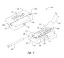
- FIG. 3is a partially schematic, isometric illustration of a cable assembly suitable for releasably coupling a patient lead or other signal delivery element to an external stimulator or other device in accordance with an embodiment of the disclosure.
- FIG. 4is an exploded, partially schematic illustration of a connector configured in accordance with an embodiment of the disclosure.
- FIG. 5is a partially schematic, isometric view of a first housing portion of an embodiment of the connector shown in FIG. 4 .
- FIG. 6is a partially schematic, isometric view of a second housing portion of an embodiment of the connector shown in FIG. 4 .
- FIGS. 7A and 7Bare partially schematic, isometric views of an embodiment of the connector shown in a partially-opened positioned and a closed position, respectively, in accordance with an embodiment of the disclosure.
- FIGS. 8A and 8Billustrate side views of a connector shown in a partially-opened position and a closed position, respectively, in accordance with an embodiment of the disclosure.
- FIG. 9is a downwardly looking oblique view of an embodiment of a second housing portion of an embodiment of the connector.
- FIG. 10illustrates a side view of an embodiment of the connector.
- aspects of the present disclosureare directed generally to couplings that may be used to connect implanted leads or other implanted signal delivery elements, with external stimulators and/or other devices positioned external to a patient.
- a spinal cord stimulation (SCS) systemfor purposes of illustration.
- the disclosed systems and methodsmay be used in the context of other patient treatment and/or patient diagnostic systems.
- FIGS. 1-10Several embodiments of representative systems and methods are described below with reference to FIGS. 1-10 . A person skilled in the relevant art will understand, however, that the disclosure may have additional embodiments, and/or that aspects of the disclosure may be practiced without several of the details of the embodiments described below.
- a patient treatment system in accordance with a particular embodimentincludes a cable assembly that in turn includes an electrical cable having a proximal end and a distal end, with a first connector attached to the cable toward the proximal end, and a second connector attached to the cable toward the distal end.
- the first connectorcan include a plurality of first connector contacts positioned to releasably connect to an external patient device, for example, an external stimulator.
- the second connectorcan include a first portion and a second portion pivotably connected to the first portion.
- the first portioncan have a slot elongated along a slot axis and positioned to receive an implantable patient signal delivery element axially along the slot axis.
- the second portioncan have a plurality of second connector contacts positioned to releasably, electrically contact the signal delivery element when the signal delivery element is positioned within the slot and the first and second portions are placed in a secured position.
- the first and second portionsare pivotable relative to each other between a closed position and a partially-opened position.
- a representative method for operating a patient treatment systemcan include implanting an implantable signal delivery element in a patient, and positioning a cable proximate to connection contacts of the implantable signal delivery device.
- the cablecan include a proximal end with a first connector having first connector contacts, and a distal end with a second connector having first and second portions.
- the methodcan further include sliding the connection contacts of the signal delivery element axially into a slot carried by the second portion of the second connector.
- the methodcan still further include pivoting at least one of the first and second portions relative to the other to electrically connect the connection contacts of the signal delivery device with second connector contacts carried by the second portion of the second connector.
- the first connectorcan be releasably connected to an external patient device, for example, an external patient stimulator.
- aspects of the foregoing systems and associated methodscan allow the practitioner to manipulate the cable assembly connectors with only one hand, and/or can improve patient comfort while the cable assembly is connected to an implanted lead or other signal delivery element.
- FIG. 1schematically illustrates a representative treatment system 100 for providing relief from chronic pain and/or other conditions, arranged relative to the general anatomy of a patient's spinal cord 191 .
- the system 100can include a pulse generator 101 , which may be implanted subcutaneously within a patient 190 and coupled to a signal delivery element 110 .
- the signal delivery element 110includes a lead or lead body 111 that carries features or elements for delivering therapy to the patient 190 after implantation.
- the pulse generator 101can be connected directly to the lead 111 , or it can be coupled to the lead 111 via a communication link 102 (e.g., an extension).
- the lead 111can include a terminal section that is releasably connected to an extension at a break 114 (shown schematically in FIG. 1 ). This allows a single type of terminal section to be used with patients of different body types (e.g., different heights).
- the terms lead and lead bodyinclude any of a number of suitable substrates and/or support members that carry devices for providing therapy signals to the patient 190 .
- the lead 111can include one or more electrodes or electrical contacts that direct electrical signals into the patient's tissue, such as to provide for patient relief.
- the signal delivery element 110can include devices other than a lead body (e.g., a paddle) that also direct electrical signals and/or other types of signals to the patient 190 .
- the pulse generator 101can transmit signals to the signal delivery element 110 that up-regulate (e.g., stimulate or excite) and/or down-regulate (e.g., block or suppress) target nerves.
- up-regulatee.g., stimulate or excite
- down-regulatee.g., block or suppress
- the terms “stimulate,” “stimulation,” and more generally, “modulation,”refer to signals that have either type of effect on the target nerves.
- the pulse generator 101can include a machine-readable (e.g., computer-readable) medium containing instructions for generating and transmitting suitable therapy signals.
- the pulse generator 101 and/or other elements of the system 100can include one or more processors 107 , memories 108 and/or input/output devices.
- the process of providing stimulation signals and executing other associated functionscan be performed by computer-executable instructions contained on computer-readable media, e.g., at the processor(s) 107 and/or memory(s) 108 .
- the pulse generator 101can include multiple portions, elements, and/or subsystems (e.g., for directing signals in accordance with multiple signal delivery parameters), housed in a single housing, as shown in FIG. 1 , or in multiple housings.
- the pulse generator 101can obtain power to generate the therapy signals from an external power source 103 .
- the external power source 103can transmit power to the implanted pulse generator 101 using electromagnetic induction (e.g., RF signals).
- the external power source 103can include an external coil 104 that communicates with a corresponding internal coil (not shown) within the implantable pulse generator 101 .
- the external power source 103can be portable for ease of use.
- the pulse generator 101can obtain the power to generate therapy signals from an internal power source, in addition to or in lieu of the external power source 103 .
- the implanted pulse generator 101can include a non-rechargeable battery or a rechargeable battery to provide such power.
- the internal power sourceincludes a rechargeable battery
- the external power source 103can be used to recharge the battery.
- the external power source 103can in turn be recharged from a suitable power source (e.g., conventional wall power).
- an external programmer 105e.g., a trial stimulator
- an external programmer 105is coupled to the signal delivery element 110 during an initial implant procedure, prior to implanting the pulse generator 101 .
- a practitionere.g., a physician and/or a company representative
- the practitioneruses a cable assembly 120 to temporarily connect the external programmer 105 to the signal delivery device 110 .
- the cable assembly 120can accordingly include a first connector 121 that is releasably connected to the external programmer 105 , and a second connector 122 that is releasably connected to the signal delivery element 110 .
- the practitionercan test the efficacy of the signal delivery element 110 in an initial position. The practitioner can then disconnect the cable assembly 120 , reposition the signal delivery element 110 , and reapply the electrical stimulation. This process can be performed iteratively until the practitioner obtains the desired position for the signal delivery device 110 .
- the practitionermay move the partially implanted signal delivery element 110 without disconnecting the cable assembly 120 . In either embodiment, the practitioner will connect and disconnect the cable assembly 120 at least once during the process. Further details of features that facilitate this process are described below with reference to FIGS. 3-10 .
- the patient 190can receive therapy via signals generated by the external programmer 105 , generally for a limited period of time. In a representative application, the patient 190 receives such therapy for a one-week trial period. During this time, the patient wears the cable assembly 120 and the external programmer 105 outside the body. Assuming the trial therapy is effective or shows the promise of being effective, the practitioner then replaces the external programmer 105 with the implanted pulse generator 101 , and programs the pulse generator 101 with parameters selected based on the experience gained during the trial period. Optionally, the practitioner can also replace the signal delivery element 110 .
- the signal delivery parameters provided by the pulse generator 101can still be updated remotely via a wireless physician's programmer (e.g., a physician's remote) 109 and/or a wireless patient programmer 106 (e.g., a patient remote).
- a wireless physician's programmere.g., a physician's remote
- a wireless patient programmer 106e.g., a patient remote
- the patient 190has control over fewer parameters than does the practitioner.
- the capability of the patient programmer 106may be limited to starting and/or stopping the pulse generator 101 , and/or adjusting stimulation amplitude.
- FIG. 2is a partially schematic illustration of a representative signal delivery device 110 that includes a lead 111 having a plurality of stimulation contacts 112 toward the distal end that are implanted within the patient.
- the lead 111includes internal wires that extend between the stimulation contacts 112 at the distal end and connection contacts 113 positioned at the proximal end.
- the connection contacts 113extend outside the patient's body and are connected to an external stimulator. After the trial period is complete, the connection contacts 113 are connected to the implanted pulse generator 101 ( FIG. 1 ).
- a stylet 160 or other delivery deviceis temporarily connected to the lead 111 to support the lead 111 as it is positioned within the patient.
- the stylet 160can include a shaft 161 and a handle 162 .
- the shaft 161is generally flexible, but more rigid than the lead 111 to allow the practitioner to insert the lead 111 and control its position during implantation.
- FIG. 3is a partially schematic, isometric illustration of a cable assembly 120 that can be releasably connected to the signal delivery element 110 shown in FIG. 2 .
- the cable assembly 120includes a cable 125 carrying a plurality of electrical conductors 126 .
- a first connector 121is positioned toward a proximal end 123 .
- a second connector 122is connected to the cable 125 toward a distal end 124 and includes second connector contacts 153 ( FIG. 4 ), also connected to the electrical conductors 126 .
- FIG. 4is a partially schematic, partially exploded isometric illustration of the cable 125 and the second connector 122 .
- the bulk of the second connector 122can be formed from ABS or another suitable biocompatible plastic or other material.
- the second connector 122includes a first portion, e.g., a first housing portion 130 pivotably connected to a second portion, e.g., a second housing portion 150 , via a hinge pin 170 . Accordingly, at least one of the first housing portion 130 and the second housing portion 150 can be pivoted relative to the other between a closed position and a partially-opened position.
- the second connector 122can have a corresponding closed configuration and partially-opened configuration, respectively.
- the first housing portion 130includes a stop opening 131 that interfaces with a stop element 151 (carried by the second housing portion 150 ) to control the pivoting motion of the first and second housing portions 130 , 150 .
- the first housing portion 130also includes a slot 132 elongated along a slot axis 133 .
- the slot 132can include a first opening 134 a positioned toward one end of the slot axis 133 , a second opening 134 b positioned toward the opposite end of the slot axis 133 , and a third opening 134 c extending along the slot axis 133 between the first opening 134 a and the second opening 134 b .
- the slot 132is positioned to receive a lead or other signal delivery device, and an associated stylet. Accordingly, the first opening 134 a can have a first width sized to receive the lead, the second opening 134 b can have a smaller second width sized to receive the stylet shaft, and the third opening 134 c can have a third width, also sized to receive the stylet shaft. As further shown in FIG. 4 , the slot 132 can include a funnel surface 137 at the first opening 134 a to facilitate sliding a lead into the slot 132 along the slot axis 133 . A ramp surface 138 at the second opening 134 b can facilitate movement of the stylet handle 162 ( FIG. 2 ) relative to the slot 132 .
- the first housing portion 130can include a first tab 135 and the second housing portion 150 can include a second tab 155 , both of which facilitate pivoting the two housing portions relative to each other.
- the two tabs 135 , 155can be offset from each other in a direction generally parallel to the slot axis 133 to operate in a manner similar to that of a change purse.
- the second housing portion 150includes two outer hinge elements 171 , each having second pin apertures 172 that slidably receive a corresponding hinge pin 170 .
- the hinge pin 170also passes through a corresponding inner hinge element carried by the first housing portion 130 .
- the second housing portion 150can carry a support member 154 that in turn carries second connector contacts 153 .
- the second connector contacts 153are electrically connected to the electrical conductors 126 ( FIG. 3 ) carried by the cable 125 .
- the second connector contacts 153project upwardly toward the first housing portion 130 so as to releasably engage with a lead placed in the slot 132 of the first housing portion 130 .
- FIG. 5is a partially schematic, isometric view of the first housing portion 130 in accordance with an embodiment of the second connector 122 shown in FIG. 4 .
- the first housing portion 130includes a stop opening 131 .
- the stop opening 131includes an elongated slot with each end of the stop opening 131 wider than the middle portion, which has pinched or narrowed sides.
- the stop opening 131may be dumbbell-shaped, and can be hourglass-shaped in another embodiment.
- FIG. 6is a partially schematic, isometric view of the second housing portion 150 in accordance with an embodiment of the second connector 122 shown in FIG. 4 .
- the second housing portion 150can include snap-fit latches 152 a , 152 b for securing the support member 154 shown in FIG. 4 .
- the second housing portion 150includes a stop element 151 .
- the stop element 151is sized to fit securely in each end of the stop opening 131 in the first housing portion 130 .
- the stop element 151includes two (or more) prongs 156 having proximal ends that are fixed relative to each other (e.g., at the second housing portion 150 ), and distal ends that are separated by a gap 157 so as to move toward and away from each other.
- the prongs 156can be made of a resilient material so as to maintain the relative positions shown in FIG. 6 in the absence of an external force.
- the stop element 151can have an outer dimension of D 1 ( FIG. 6 ), and the ends of the stop opening 131 ( FIG. 5 ) can have an inner dimension of D 2 .
- D 2is less than D 1 (e.g., 0.95 D 1 ) so that the stop element 151 is snugly received at either end of the stop opening 131 .
- the middle portion of the stop openingcan have a still smaller inner dimension D 3 (e.g., 0.8 D 1 ) to resist relative motion between the first housing portion 130 (which carries the stop opening 131 ) and the second housing portion 150 (which carries the stop element 151 ).
- FIGS. 7A and 7Bare partially schematic, isometric views of an embodiment of the second connector shown in a partially-opened positioned ( FIG. 7A ) and a closed position ( FIG. 7B ) in accordance with an embodiment of the disclosure.
- FIG. 7Aillustrates the second connector 122 in the partially-opened position in which the stop element 151 is in a first location in the stop opening 131 .
- FIG. 7Billustrates the second connector 122 in the closed position in which the stop element 151 is in a second location in the stop opening 131 .
- the location of the stop element 151 relative to the stop opening 131can change as the second connector 122 moves from the first, partially-opened position to the second, closed position.
- the change in relative locationresults from the relative movement of the first housing portion 130 and the second housing portion 150 , regardless of which housing portion moves relative to the other.
- the prongs 156move toward each other to fit through the narrow portion of the stop opening 131 .
- the prongs 156reach either end of the stop opening 131 , they move apart from each other to hold the second connector 122 in the desired position (closed or partially open) until the practitioner deliberately changes the position.
- the stop element 151resists relative movement of the housing portions 130 , 150 so that the second connector 122 is less likely to be opened or closed inadvertently.
- FIGS. 8A and 8Bare cross-sectional illustrations of the second connector 122 shown in the partially-opened position ( FIG. 8A ) and the closed position ( FIG. 8B ).
- FIG. 8Athe first housing portion 130 is pivoted away from the second housing portion 150 to the partially-opened position.
- a lead 111is inserted into the first opening 134 a , but does not yet contact the second connector contacts 153 carried by the support member 154 of the second housing portion 150 .
- the first housing portion 130is prevented from over-rotating relative to the second housing portion 150 because the stop element 151 is received at one end of the stop opening 131 of the first housing portion 130 .
- the stop opening 131can be sized to prevent the first and second housing portions 130 , 150 from rotating away from each other by an angle between 0.5° and 45°, inclusive.
- the amount of rotationcan be less, for example, between 3° and 15°, inclusive, between 5° and 8°, inclusive, or between 6.5° and 7°, inclusive.
- the particular angular valuecan be selected so that the connection contacts of the lead just disengage from the second connector contacts 153 when the second connector 122 is in the partially-opened position.
- it is expected that limiting the relative rotation of the two housing portions 130 , 150can facilitate the user's ability to secure and/or unsecure the second connector 122 , for example, by facilitating single handed operation of the second connector 122 .
- FIG. 8Billustrates the second connector 122 in the closed position, in which the stop element 151 is in the second location in the stop opening 131 .
- the first and second housing portions 130 , 150have been pivoted toward each other, so that the lead 111 engages with the second connector contacts 153 .
- At least a portion of each second connector contact 153can be received in the slot 132 so that the second connector contacts 153 do not interfere with moving the housing portions 130 , 150 toward each other to the secured position.
- the second connector 122can remain in the secured position until positively acted upon by the practitioner.
- FIG. 9illustrates an embodiment of the second housing portion 150 .
- the snap-fit latches 152 a , 152 breceive and secure the support member 154 within the second housing 150 .
- FIG. 10is a cross-sectional side view of the second housing portion 150 . As shown in FIG. 10 , the support member 154 is secured into the second housing portion by snap-fit latches 152 a , 152 b.
- the lead 111 or other signal delivery element 110can be introduced into the second connector 122 by sliding it axially into and along the slot 132 , without at the same time engaging the connection contacts 113 with the second connector contacts 153 .
- the lead 111can be moved into the slot 132 easily, with low frictional resistance, and with a reduced likelihood for dislodging or otherwise moving the lead 111 relative to the patient.
- the practitionercan do so with only one hand, allowing the practitioner to hold the lead 111 in place relative to the patient with the other hand.
- the practitioner's handcan provide both the moving force and the reaction force imparted to the second connector 122 , which reduces the likelihood for the second connector 122 to slip out of the practitioner's grasp.
- the angle between the two housing portions 130 , 150is relatively small when the second connector 122 is in the partially-opened configuration.
- the anglecan be between 0.5° and 45° in a particular embodiment, between 3° and 15° in another particular embodiment, between 5° and 8° in a further particular embodiment, and between 6.5° and 7° in still a further particular embodiment. Accordingly, the amount of hand movement required to secure and/or unsecure the second connector 122 is relatively small, which decreases the likelihood that the practitioner will fumble with the second connector 122 .
- the second connector 122has a relatively small footprint (e.g., projected area, generally normal to the major surfaces of the first or second housing portions 130 , 150 ).
- a relatively small footprinte.g., projected area, generally normal to the major surfaces of the first or second housing portions 130 , 150 .
- An expected advantage of this featureis that the small size makes the second connector 122 easier to manipulate.
- Another expected advantage of this featureis that the second connector will be less bulky and therefore more comfortable for the patient to wear during the trial period.
- the second connectorcan include other arrangements for securing one housing portion relative to the other, and/or for halting the axial movement of the lead or other signal delivery element positioned in the second connector.
- the stop element 151can, in some embodiments, have a configuration different than the multi-pronged configuration shown in the figures. The relative positions of the stop element and the stop slot can be reversed, with the stop element carried by the first housing portion, and the stop slot carried by the second housing portion.
- the practitionercan leave the second connector attached to the implanted signal delivery element while the signal delivery element is repositioned, rather than disconnecting and reconnecting the connector with each new signal delivery element position.
- the signal delivery elementcan have features different than those shown in FIG. 2 , and/or can be supported by a device other than a stylet.
- advantages associated with certain embodimentshave been described in the context of those embodiments, other embodiments may also exhibit such advantages and not all embodiments need necessarily exhibit such advantages to fall within the scope of the present disclosure. Accordingly, the disclosure can encompass other embodiments not expressly described or shown herein.
Landscapes
- Health & Medical Sciences (AREA)
- Engineering & Computer Science (AREA)
- Biomedical Technology (AREA)
- Nuclear Medicine, Radiotherapy & Molecular Imaging (AREA)
- Radiology & Medical Imaging (AREA)
- Life Sciences & Earth Sciences (AREA)
- Animal Behavior & Ethology (AREA)
- General Health & Medical Sciences (AREA)
- Public Health (AREA)
- Veterinary Medicine (AREA)
- Neurology (AREA)
- Neurosurgery (AREA)
- Orthopedic Medicine & Surgery (AREA)
- Cardiology (AREA)
- Heart & Thoracic Surgery (AREA)
- Electrotherapy Devices (AREA)
Abstract
Description
Claims (24)
Priority Applications (1)
| Application Number | Priority Date | Filing Date | Title |
|---|---|---|---|
| US14/678,785US9789321B2 (en) | 2015-04-03 | 2015-04-03 | Couplings for implanted leads and external stimulators, and associated systems and methods |
Applications Claiming Priority (1)
| Application Number | Priority Date | Filing Date | Title |
|---|---|---|---|
| US14/678,785US9789321B2 (en) | 2015-04-03 | 2015-04-03 | Couplings for implanted leads and external stimulators, and associated systems and methods |
Publications (2)
| Publication Number | Publication Date |
|---|---|
| US20160287881A1 US20160287881A1 (en) | 2016-10-06 |
| US9789321B2true US9789321B2 (en) | 2017-10-17 |
Family
ID=57015594
Family Applications (1)
| Application Number | Title | Priority Date | Filing Date |
|---|---|---|---|
| US14/678,785ActiveUS9789321B2 (en) | 2015-04-03 | 2015-04-03 | Couplings for implanted leads and external stimulators, and associated systems and methods |
Country Status (1)
| Country | Link |
|---|---|
| US (1) | US9789321B2 (en) |
Cited By (13)
| Publication number | Priority date | Publication date | Assignee | Title |
|---|---|---|---|---|
| US11116975B2 (en) | 2015-11-09 | 2021-09-14 | Bluewind Medical Ltd. | Optimization of application of current |
| US11213685B2 (en) | 2017-06-13 | 2022-01-04 | Bluewind Medical Ltd. | Antenna configuration |
| US11278719B2 (en) | 2012-12-06 | 2022-03-22 | Bluewind Medical Ltd. | Delivery of implantable neurostimulators |
| US11400299B1 (en) | 2021-09-14 | 2022-08-02 | Rainbow Medical Ltd. | Flexible antenna for stimulator |
| US11439833B2 (en) | 2016-11-23 | 2022-09-13 | Bluewind Medical Ltd. | Implant-delivery tool |
| US20230024575A1 (en)* | 2021-07-23 | 2023-01-26 | Dongguan Ceesing Intelligent Device Manufacturing Co., Ltd | Unidirectional free-pulling data cable |
| US11648410B2 (en) | 2012-01-26 | 2023-05-16 | Bluewind Medical Ltd. | Wireless neurostimulators |
| US11766561B2 (en) | 2016-07-18 | 2023-09-26 | Nalu Medical, Inc. | Methods and systems for treating pelvic disorders and pain conditions |
| US11826569B2 (en) | 2017-02-24 | 2023-11-28 | Nalu Medical, Inc. | Apparatus with sequentially implanted stimulators |
| US11938327B2 (en) | 2016-03-21 | 2024-03-26 | Nalu Medical, Inc. | Devices and methods for positioning external devices in relation to implanted devices |
| US12186563B2 (en) | 2014-06-21 | 2025-01-07 | Nalu Medical, Inc. | Method and apparatus for neuromodulation treatments of pain and other conditions |
| US12201829B2 (en) | 2017-05-09 | 2025-01-21 | Nalu Medical, Inc. | Stimulation apparatus |
| US12390650B2 (en) | 2016-12-30 | 2025-08-19 | Nalu Medical, Inc. | Stimulation apparatus |
Citations (112)
| Publication number | Priority date | Publication date | Assignee | Title |
|---|---|---|---|---|
| US4211462A (en) | 1979-01-22 | 1980-07-08 | Stewart Stamping Corporation, A Division Of Insilco Corp. | Electrical connector for termination cords with improved locking means |
| US4466690A (en) | 1981-06-24 | 1984-08-21 | Peter Osypka | Connector for the conductors of implanted medical devices |
| US4498482A (en) | 1979-12-13 | 1985-02-12 | Medtronic, Inc. | Transvenous pacing lead having improved stylet |
| EP0158316A2 (en) | 1984-04-10 | 1985-10-16 | Walsh Manufacturing (Mississauga) Limited | Anastomosis devices and kit |
| US4573448A (en) | 1983-10-05 | 1986-03-04 | Pilling Co. | Method for decompressing herniated intervertebral discs |
| US4683895A (en) | 1985-07-25 | 1987-08-04 | Cordis Corporation | Suture sleeve anchoring device |
| US4764132A (en) | 1986-03-28 | 1988-08-16 | Siemens-Pacesetter, Inc. | Pacemaker connector block for proximal ring electrode |
| US4796642A (en) | 1987-12-28 | 1989-01-10 | Cordis Leads, Inc. | Pacing lead stylet |
| US4898173A (en) | 1988-04-22 | 1990-02-06 | Medtronic, Inc. | In-line pacemaker connector system |
| WO1990003824A1 (en) | 1988-10-12 | 1990-04-19 | Huntington Medical Research Institutes | Bidirectional helical electrode for nerve stimulation |
| US4934367A (en) | 1988-04-22 | 1990-06-19 | Medtronic, Inc. | In-line pacemaker connector system |
| US5042486A (en) | 1989-09-29 | 1991-08-27 | Siemens Aktiengesellschaft | Catheter locatable with non-ionizing field and method for locating same |
| US5052375A (en) | 1990-02-21 | 1991-10-01 | John G. Stark | Instrumented orthopedic restraining device and method of use |
| US5070605A (en) | 1988-04-22 | 1991-12-10 | Medtronic, Inc. | Method for making an in-line pacemaker connector system |
| US5072458A (en) | 1987-05-07 | 1991-12-17 | Capintec, Inc. | Vest for use in an ambulatory physiological evaluation system including cardiac monitoring |
| US5211165A (en) | 1991-09-03 | 1993-05-18 | General Electric Company | Tracking system to follow the position and orientation of a device with radiofrequency field gradients |
| US5241957A (en) | 1991-11-18 | 1993-09-07 | Medtronic, Inc. | Bipolar temporary pacing lead and connector and permanent bipolar nerve wire |
| US5257636A (en) | 1991-04-02 | 1993-11-02 | Steven J. White | Apparatus for determining position of an endothracheal tube |
| US5261395A (en) | 1992-03-02 | 1993-11-16 | Cardiac Pacemaker, Inc. | Tooless pulse generator to lead connection |
| US5325873A (en) | 1992-07-23 | 1994-07-05 | Abbott Laboratories | Tube placement verifier system |
| US5354326A (en) | 1993-01-27 | 1994-10-11 | Medtronic, Inc. | Screening cable connector for interface to implanted lead |
| US5375596A (en) | 1992-09-29 | 1994-12-27 | Hdc Corporation | Method and apparatus for determining the position of catheters, tubes, placement guidewires and implantable ports within biological tissue |
| US5425367A (en) | 1991-09-04 | 1995-06-20 | Navion Biomedical Corporation | Catheter depth, position and orientation location system |
| US5557210A (en) | 1992-11-20 | 1996-09-17 | Pacesetter, Inc. | Universal cable connector for temporarily connecting implantable stimulation leads and implantable stimulation devices with a non-implantable system analyzer |
| US5560358A (en) | 1994-09-08 | 1996-10-01 | Radionics, Inc. | Connector design for multi-contact medical electrode |
| US5727553A (en) | 1996-03-25 | 1998-03-17 | Saad; Saad A. | Catheter with integral electromagnetic location identification device |
| US5730628A (en) | 1996-09-25 | 1998-03-24 | Pacesetter, Inc. | Multi-contact connector for an implantable medical device |
| US5848126A (en) | 1993-11-26 | 1998-12-08 | Kabushiki Kaisha Toshiba | Radiation computed tomography apparatus |
| US5931861A (en) | 1997-04-25 | 1999-08-03 | Medtronic, Inc. | Medical lead adaptor having rotatable locking clip mechanism |
| US6039685A (en) | 1998-09-14 | 2000-03-21 | St. Croix Medical, Inc. | Ventable connector with seals |
| US6106460A (en) | 1998-03-26 | 2000-08-22 | Scimed Life Systems, Inc. | Interface for controlling the display of images of diagnostic or therapeutic instruments in interior body regions and related data |
| US6263230B1 (en) | 1997-05-08 | 2001-07-17 | Lucent Medical Systems, Inc. | System and method to determine the location and orientation of an indwelling medical device |
| US6325778B1 (en) | 1996-05-20 | 2001-12-04 | Medtronic Percusurge, Inc. | Low profile catheter valve and inflation adaptor |
| US20020052640A1 (en) | 2000-08-04 | 2002-05-02 | Steve Bigus | Sheath for self-expanding stents |
| US6397108B1 (en) | 2000-04-03 | 2002-05-28 | Medtronic Inc. | Safety adaptor for temporary medical leads |
| US6477427B1 (en) | 2000-03-31 | 2002-11-05 | Medtronic Inc. | Implantable stimulation lead and method of manufacture |
| US20020173718A1 (en) | 2001-05-20 | 2002-11-21 | Mordechai Frisch | Array system and method for locating an in vivo signal source |
| US6516807B1 (en) | 1994-10-11 | 2003-02-11 | Ep Technologies, Inc. | System and methods for locating and guiding operative elements within interior body regions |
| US20030062048A1 (en) | 2001-06-14 | 2003-04-03 | Gradon Lewis George | Breathing assistance apparatus |
| US20030114752A1 (en) | 1999-04-20 | 2003-06-19 | Jaimie Henderson | Instrument guidance method and system for image guided surgery |
| US20030120150A1 (en) | 2001-12-21 | 2003-06-26 | Assaf Govari | Wireless position sensor |
| US20030136418A1 (en) | 1999-10-29 | 2003-07-24 | Medtronic, Inc. | Tactile feedback for indicating validity of communication link with an implantable medical device |
| US20030228805A1 (en) | 2002-06-07 | 2003-12-11 | Dieter Schwarz | Device for electrical connection of a power lead to an electrode, in particular a medical skin electrode |
| US6671534B2 (en) | 2000-04-19 | 2003-12-30 | Ad-Tech Medical Instrument Corporation | Electrical connector for multi-contact medical electrodes |
| US20040034392A1 (en) | 2002-08-16 | 2004-02-19 | Cardiac Pacemakers, Inc. | Connector module replacement for implantable medical stimulators |
| US20040087877A1 (en) | 2000-08-23 | 2004-05-06 | Besz William John | Catheter locator apparatus and method of use |
| US20040097803A1 (en) | 2002-11-20 | 2004-05-20 | Dorin Panescu | 3-D catheter localization using permanent magnets with asymmetrical properties about their longitudinal axis |
| US20040176683A1 (en) | 2003-03-07 | 2004-09-09 | Katherine Whitin | Method and apparatus for tracking insertion depth |
| US20040230268A1 (en) | 2003-05-13 | 2004-11-18 | Medtronic, Inc. | Medical lead adaptor assembly |
| US20050049486A1 (en) | 2003-08-28 | 2005-03-03 | Urquhart Steven J. | Method and apparatus for performing stereotactic surgery |
| US20050049664A1 (en) | 2003-08-29 | 2005-03-03 | Harris Charmaine K. | Percutaneous flat lead introducer |
| US6875571B2 (en) | 1991-08-22 | 2005-04-05 | The Board Of Trustees Of The Leland Stanford Junior University | NF-AT polypeptides and polynucleotides and screening methods for immunosuppressive agents |
| US20050075684A1 (en) | 2003-10-02 | 2005-04-07 | Phillips William C. | Neurostimulator programmer with clothing attachable antenna |
| US20050228221A1 (en) | 2002-10-29 | 2005-10-13 | Olympus Corporation | Endoscope information processor and processing method |
| US20060030918A1 (en) | 2004-08-04 | 2006-02-09 | Chinn Kenny K | Operating room lead connector |
| US20060148326A1 (en) | 2005-01-04 | 2006-07-06 | Putz David A | Multiple-use, stimulation-accommodating connector |
| US20060253160A1 (en) | 2003-03-12 | 2006-11-09 | Transoma Medical, Inc. | Devices and methods for detecting and treating inadequate tissue perfusion |
| US20070191903A1 (en) | 2006-01-24 | 2007-08-16 | Bruinstroop Jan K P | Method for controlling micturition |
| US20070249901A1 (en) | 2003-03-07 | 2007-10-25 | Ohline Robert M | Instrument having radio frequency identification systems and methods for use |
| US7299095B1 (en) | 2003-12-17 | 2007-11-20 | Pacesetter, Inc. | Electrical contact assembly |
| US20080097475A1 (en) | 2006-09-08 | 2008-04-24 | Viasys Holdings, Inc. | Medical device position guidance system with wireless connectivity between a noninvasive device and an invasive device |
| US7383090B2 (en) | 2003-10-20 | 2008-06-03 | Greatbatch Ltd. | Connection for a coiled lead to an electrical contact for an implantable medical device |
| US20080140087A1 (en) | 2006-05-17 | 2008-06-12 | Hansen Medical Inc. | Robotic instrument system |
| US7421297B2 (en) | 2005-03-31 | 2008-09-02 | Medtronic, Inc. | Monopolar stimulation assembly including at least one remote electrode |
| US7425142B1 (en) | 2007-03-16 | 2008-09-16 | Ad-Tech Medical Instrument Corp. | Electrical connector for an in-body multi-contact medical electrode device |
| US20080262430A1 (en) | 2007-04-18 | 2008-10-23 | Access Scientific, Inc. | Access device |
| US20080275467A1 (en) | 2007-05-02 | 2008-11-06 | Siemens Corporate Research, Inc. | Intraoperative guidance for endovascular interventions via three-dimensional path planning, x-ray fluoroscopy, and image overlay |
| US20080319311A1 (en) | 2007-06-22 | 2008-12-25 | General Electric Company | System and method for accuracy verification for image based surgical navigation |
| US20090048638A1 (en) | 2007-08-15 | 2009-02-19 | Gerry Rey | Connector assembly for use with medical devices |
| US20090069803A1 (en) | 2007-09-10 | 2009-03-12 | Medtronic, Inc. | Selective depth electrode deployment for electrical stimulation |
| US20090112272A1 (en) | 2007-10-31 | 2009-04-30 | Boston Scientific Neuromodulation Corporation | Connector assemblies for implantable stimulators |
| US20090125060A1 (en) | 2007-11-09 | 2009-05-14 | Rivard Adam J | Compression control lead anchoring device |
| US20090132016A1 (en) | 2007-11-20 | 2009-05-21 | Ad-Tech Medical Instrument Corp. | Electrical Connector with Canopy for an In-Body Multi-Contact Medical Electrode Device |
| US20090233491A1 (en) | 2008-03-12 | 2009-09-17 | Boston Scientific Neuromodulation Corporation | Low-profile connector for a neurostimulation lead |
| WO2009129329A1 (en) | 2008-04-16 | 2009-10-22 | Nevro Corporation | Treatment devices with delivery-activated inflatable members, and associated systems and methods for treating the spinal cord and other tissues |
| US20100094116A1 (en) | 2008-10-07 | 2010-04-15 | Lucent Medical Systems, Inc. | Percutaneous magnetic gastrostomy |
| US7702379B2 (en) | 2004-08-25 | 2010-04-20 | General Electric Company | System and method for hybrid tracking in surgical navigation |
| US20100152538A1 (en) | 2008-12-17 | 2010-06-17 | Gleason Christopher M | Device for preventing endoscope damage by errant laser fire in a surgical laser |
| US20100256696A1 (en) | 2009-04-07 | 2010-10-07 | Boston Scientific Neuromodulation Corporation | Anchoring Units For Implantable Electrical Stimulation Systems And Methods Of Making And Using |
| US7810996B1 (en) | 2007-01-29 | 2010-10-12 | Steadman Philippon Research Institute | Dual fluoroscopy systems and methods |
| US20100267265A1 (en) | 2009-04-20 | 2010-10-21 | Farshid Dilmaghanian | In-line connector stack with testing capability |
| US20100274336A1 (en) | 2009-04-27 | 2010-10-28 | Boston Scientific Neuromodulation Corporation | Torque lock anchor and methods and devices using the anchor |
| US20100286551A1 (en) | 2009-05-08 | 2010-11-11 | Rhythmia Medical, Inc. | Impedance Based Anatomy Generation |
| US20100305670A1 (en) | 2009-05-26 | 2010-12-02 | Hall Peter C | Method and Devices for Coupling a Lead Conductor Member to a Functional Component |
| CN101920065A (en) | 2009-06-17 | 2010-12-22 | 宇大伟 | Cardiac pacemaker |
| US20100324414A1 (en) | 2007-02-08 | 2010-12-23 | Rhythmia Medical, Inc., A Delaware Corporation | Catheter tracking and endocardium representation generation |
| US7881806B2 (en) | 2006-10-31 | 2011-02-01 | Medtronic, Inc. | Medical lead delivery device |
| US20110031961A1 (en) | 2008-02-04 | 2011-02-10 | Durand Keith V | Endotracheal tube sensor |
| US20110046617A1 (en) | 2005-07-21 | 2011-02-24 | Tyco Healthcare Group, Lp | Methods for treating a hollow anatomical structure |
| US20110071593A1 (en)* | 2009-09-18 | 2011-03-24 | Nevro Corporation | Couplings for implanted leads and external stimulators, and associated systems and methods |
| US20110071604A1 (en) | 2004-03-30 | 2011-03-24 | Wahlstrand Carl D | MRI-Safe Implantable Lead |
| US20110106100A1 (en) | 2009-10-30 | 2011-05-05 | Medtronic, Inc. | Steerable percutaneous paddle stimulation lead |
| US20110106052A1 (en) | 2009-10-30 | 2011-05-05 | Huihua Kenny Chiang | Ultrasonic positioning device for epidural space and method using the same |
| US20110112609A1 (en) | 2009-11-09 | 2011-05-12 | Boston Scientific Neuromodulation Corporation | Automatic lead identification using electric field fingerprinting |
| US20110144468A1 (en) | 2004-06-10 | 2011-06-16 | Medtronic Urinary Solutions, Inc. | Systems and methods of neuromodulation stimulation for the restoration of sexual function |
| US20110160568A1 (en) | 2009-12-30 | 2011-06-30 | Medtronic, Inc. | Lead Tracking and Positioning System and Method |
| US20110166621A1 (en) | 2006-06-20 | 2011-07-07 | Ebr Systems, Inc. | Systems and methods for implantable leadless spine stimulation |
| US20110167630A1 (en) | 2003-09-30 | 2011-07-14 | Medtronic, Inc. | Field Steerable Electrical Stimulation Paddle, Lead System, and Medical Device Incorporating the Same |
| US20110178573A1 (en) | 2009-04-27 | 2011-07-21 | Boston Scientific Neuromodulation Corporation | Torque lock anchor and methods and devices using the anchor |
| US20110184488A1 (en) | 2007-03-15 | 2011-07-28 | Dirk De Ridder | Spinal cord stimulation to treat pain |
| US7996055B2 (en) | 2006-12-29 | 2011-08-09 | St. Jude Medical, Atrial Fibrillation Division, Inc. | Cardiac navigation system including electrode array for use therewith |
| US20110202097A1 (en) | 2006-04-28 | 2011-08-18 | Medtronic, Inc. | System and method for electrically probing and providing medical electrical stimulation |
| US20110224710A1 (en) | 2004-10-15 | 2011-09-15 | Bleich Jeffery L | Methods, systems and devices for carpal tunnel release |
| US20110224682A1 (en) | 2010-03-11 | 2011-09-15 | Westlund Randy W | Methods of implanting electrode leads for use with implantable neuromuscular electrical stimulator |
| US20110230943A1 (en) | 2010-03-17 | 2011-09-22 | Greatbatch Ltd. | Implantable lead for an active medical device having an inductor design minimizing eddy current losses |
| US8036756B2 (en) | 2001-08-31 | 2011-10-11 | Medtronics Inc | Implantable medical electrical stimulation lead fixation method and apparatus |
| US8078280B2 (en) | 2003-04-25 | 2011-12-13 | Medtronic, Inc. | Implantable biomedical electrical connectors having integral side and inner walls |
| US20120083856A1 (en) | 2010-09-30 | 2012-04-05 | Nevro Corporation | Systems and methods for positioning implanted devices in a patient |
| US20120083709A1 (en) | 2010-09-30 | 2012-04-05 | Nevro Corporation | Systems and methods for detecting intrathecal penetration |
| US20120232626A1 (en) | 2011-03-11 | 2012-09-13 | Greatbatch Ltd. | Anchor sleeve for implantable lead |
| US8494652B2 (en) | 2010-08-09 | 2013-07-23 | Advanced Neuromodulation Systems, Inc. | Implantable medical anchor |
| US20160059006A1 (en)* | 2014-08-26 | 2016-03-03 | Pacesetter, Inc. | Cardiac lead with snap-lock construction of integrated distal tip assembly |
- 2015
- 2015-04-03USUS14/678,785patent/US9789321B2/enactiveActive
Patent Citations (115)
| Publication number | Priority date | Publication date | Assignee | Title |
|---|---|---|---|---|
| US4211462A (en) | 1979-01-22 | 1980-07-08 | Stewart Stamping Corporation, A Division Of Insilco Corp. | Electrical connector for termination cords with improved locking means |
| US4498482A (en) | 1979-12-13 | 1985-02-12 | Medtronic, Inc. | Transvenous pacing lead having improved stylet |
| US4466690A (en) | 1981-06-24 | 1984-08-21 | Peter Osypka | Connector for the conductors of implanted medical devices |
| US4573448A (en) | 1983-10-05 | 1986-03-04 | Pilling Co. | Method for decompressing herniated intervertebral discs |
| EP0158316A2 (en) | 1984-04-10 | 1985-10-16 | Walsh Manufacturing (Mississauga) Limited | Anastomosis devices and kit |
| US4683895A (en) | 1985-07-25 | 1987-08-04 | Cordis Corporation | Suture sleeve anchoring device |
| US4764132A (en) | 1986-03-28 | 1988-08-16 | Siemens-Pacesetter, Inc. | Pacemaker connector block for proximal ring electrode |
| US5072458A (en) | 1987-05-07 | 1991-12-17 | Capintec, Inc. | Vest for use in an ambulatory physiological evaluation system including cardiac monitoring |
| US4796642A (en) | 1987-12-28 | 1989-01-10 | Cordis Leads, Inc. | Pacing lead stylet |
| US4934367A (en) | 1988-04-22 | 1990-06-19 | Medtronic, Inc. | In-line pacemaker connector system |
| US5070605A (en) | 1988-04-22 | 1991-12-10 | Medtronic, Inc. | Method for making an in-line pacemaker connector system |
| US4898173A (en) | 1988-04-22 | 1990-02-06 | Medtronic, Inc. | In-line pacemaker connector system |
| WO1990003824A1 (en) | 1988-10-12 | 1990-04-19 | Huntington Medical Research Institutes | Bidirectional helical electrode for nerve stimulation |
| US5042486A (en) | 1989-09-29 | 1991-08-27 | Siemens Aktiengesellschaft | Catheter locatable with non-ionizing field and method for locating same |
| US5052375A (en) | 1990-02-21 | 1991-10-01 | John G. Stark | Instrumented orthopedic restraining device and method of use |
| US5257636A (en) | 1991-04-02 | 1993-11-02 | Steven J. White | Apparatus for determining position of an endothracheal tube |
| US6875571B2 (en) | 1991-08-22 | 2005-04-05 | The Board Of Trustees Of The Leland Stanford Junior University | NF-AT polypeptides and polynucleotides and screening methods for immunosuppressive agents |
| US5211165A (en) | 1991-09-03 | 1993-05-18 | General Electric Company | Tracking system to follow the position and orientation of a device with radiofrequency field gradients |
| US5425367A (en) | 1991-09-04 | 1995-06-20 | Navion Biomedical Corporation | Catheter depth, position and orientation location system |
| US5241957A (en) | 1991-11-18 | 1993-09-07 | Medtronic, Inc. | Bipolar temporary pacing lead and connector and permanent bipolar nerve wire |
| US5261395A (en) | 1992-03-02 | 1993-11-16 | Cardiac Pacemaker, Inc. | Tooless pulse generator to lead connection |
| US5325873A (en) | 1992-07-23 | 1994-07-05 | Abbott Laboratories | Tube placement verifier system |
| US5375596A (en) | 1992-09-29 | 1994-12-27 | Hdc Corporation | Method and apparatus for determining the position of catheters, tubes, placement guidewires and implantable ports within biological tissue |
| US5557210A (en) | 1992-11-20 | 1996-09-17 | Pacesetter, Inc. | Universal cable connector for temporarily connecting implantable stimulation leads and implantable stimulation devices with a non-implantable system analyzer |
| US5354326A (en) | 1993-01-27 | 1994-10-11 | Medtronic, Inc. | Screening cable connector for interface to implanted lead |
| US5848126A (en) | 1993-11-26 | 1998-12-08 | Kabushiki Kaisha Toshiba | Radiation computed tomography apparatus |
| US5560358A (en) | 1994-09-08 | 1996-10-01 | Radionics, Inc. | Connector design for multi-contact medical electrode |
| US6516807B1 (en) | 1994-10-11 | 2003-02-11 | Ep Technologies, Inc. | System and methods for locating and guiding operative elements within interior body regions |
| US5727553A (en) | 1996-03-25 | 1998-03-17 | Saad; Saad A. | Catheter with integral electromagnetic location identification device |
| US6325778B1 (en) | 1996-05-20 | 2001-12-04 | Medtronic Percusurge, Inc. | Low profile catheter valve and inflation adaptor |
| US5730628A (en) | 1996-09-25 | 1998-03-24 | Pacesetter, Inc. | Multi-contact connector for an implantable medical device |
| US6192278B1 (en) | 1997-04-25 | 2001-02-20 | Medtronic, Inc. | Medical lead adaptor |
| US5931861A (en) | 1997-04-25 | 1999-08-03 | Medtronic, Inc. | Medical lead adaptor having rotatable locking clip mechanism |
| US6263230B1 (en) | 1997-05-08 | 2001-07-17 | Lucent Medical Systems, Inc. | System and method to determine the location and orientation of an indwelling medical device |
| US6106460A (en) | 1998-03-26 | 2000-08-22 | Scimed Life Systems, Inc. | Interface for controlling the display of images of diagnostic or therapeutic instruments in interior body regions and related data |
| US6039685A (en) | 1998-09-14 | 2000-03-21 | St. Croix Medical, Inc. | Ventable connector with seals |
| US20030114752A1 (en) | 1999-04-20 | 2003-06-19 | Jaimie Henderson | Instrument guidance method and system for image guided surgery |
| US20030136418A1 (en) | 1999-10-29 | 2003-07-24 | Medtronic, Inc. | Tactile feedback for indicating validity of communication link with an implantable medical device |
| US6477427B1 (en) | 2000-03-31 | 2002-11-05 | Medtronic Inc. | Implantable stimulation lead and method of manufacture |
| US6397108B1 (en) | 2000-04-03 | 2002-05-28 | Medtronic Inc. | Safety adaptor for temporary medical leads |
| US6671534B2 (en) | 2000-04-19 | 2003-12-30 | Ad-Tech Medical Instrument Corporation | Electrical connector for multi-contact medical electrodes |
| US20020052640A1 (en) | 2000-08-04 | 2002-05-02 | Steve Bigus | Sheath for self-expanding stents |
| US20040087877A1 (en) | 2000-08-23 | 2004-05-06 | Besz William John | Catheter locator apparatus and method of use |
| US20020173718A1 (en) | 2001-05-20 | 2002-11-21 | Mordechai Frisch | Array system and method for locating an in vivo signal source |
| US20030062048A1 (en) | 2001-06-14 | 2003-04-03 | Gradon Lewis George | Breathing assistance apparatus |
| US8036756B2 (en) | 2001-08-31 | 2011-10-11 | Medtronics Inc | Implantable medical electrical stimulation lead fixation method and apparatus |
| US20030120150A1 (en) | 2001-12-21 | 2003-06-26 | Assaf Govari | Wireless position sensor |
| US20030228805A1 (en) | 2002-06-07 | 2003-12-11 | Dieter Schwarz | Device for electrical connection of a power lead to an electrode, in particular a medical skin electrode |
| US20040034392A1 (en) | 2002-08-16 | 2004-02-19 | Cardiac Pacemakers, Inc. | Connector module replacement for implantable medical stimulators |
| US20050228221A1 (en) | 2002-10-29 | 2005-10-13 | Olympus Corporation | Endoscope information processor and processing method |
| US20040097803A1 (en) | 2002-11-20 | 2004-05-20 | Dorin Panescu | 3-D catheter localization using permanent magnets with asymmetrical properties about their longitudinal axis |
| US20040176683A1 (en) | 2003-03-07 | 2004-09-09 | Katherine Whitin | Method and apparatus for tracking insertion depth |
| US20070249901A1 (en) | 2003-03-07 | 2007-10-25 | Ohline Robert M | Instrument having radio frequency identification systems and methods for use |
| US20060253160A1 (en) | 2003-03-12 | 2006-11-09 | Transoma Medical, Inc. | Devices and methods for detecting and treating inadequate tissue perfusion |
| US8078280B2 (en) | 2003-04-25 | 2011-12-13 | Medtronic, Inc. | Implantable biomedical electrical connectors having integral side and inner walls |
| US20040230268A1 (en) | 2003-05-13 | 2004-11-18 | Medtronic, Inc. | Medical lead adaptor assembly |
| US20050049486A1 (en) | 2003-08-28 | 2005-03-03 | Urquhart Steven J. | Method and apparatus for performing stereotactic surgery |
| US20050049664A1 (en) | 2003-08-29 | 2005-03-03 | Harris Charmaine K. | Percutaneous flat lead introducer |
| US20110167630A1 (en) | 2003-09-30 | 2011-07-14 | Medtronic, Inc. | Field Steerable Electrical Stimulation Paddle, Lead System, and Medical Device Incorporating the Same |
| US20050075684A1 (en) | 2003-10-02 | 2005-04-07 | Phillips William C. | Neurostimulator programmer with clothing attachable antenna |
| US7383090B2 (en) | 2003-10-20 | 2008-06-03 | Greatbatch Ltd. | Connection for a coiled lead to an electrical contact for an implantable medical device |
| US7299095B1 (en) | 2003-12-17 | 2007-11-20 | Pacesetter, Inc. | Electrical contact assembly |
| US20110071604A1 (en) | 2004-03-30 | 2011-03-24 | Wahlstrand Carl D | MRI-Safe Implantable Lead |
| US20110144468A1 (en) | 2004-06-10 | 2011-06-16 | Medtronic Urinary Solutions, Inc. | Systems and methods of neuromodulation stimulation for the restoration of sexual function |
| US20060030918A1 (en) | 2004-08-04 | 2006-02-09 | Chinn Kenny K | Operating room lead connector |
| US7702379B2 (en) | 2004-08-25 | 2010-04-20 | General Electric Company | System and method for hybrid tracking in surgical navigation |
| US20110224710A1 (en) | 2004-10-15 | 2011-09-15 | Bleich Jeffery L | Methods, systems and devices for carpal tunnel release |
| US20060148326A1 (en) | 2005-01-04 | 2006-07-06 | Putz David A | Multiple-use, stimulation-accommodating connector |
| US7421297B2 (en) | 2005-03-31 | 2008-09-02 | Medtronic, Inc. | Monopolar stimulation assembly including at least one remote electrode |
| US20110046617A1 (en) | 2005-07-21 | 2011-02-24 | Tyco Healthcare Group, Lp | Methods for treating a hollow anatomical structure |
| US20070191903A1 (en) | 2006-01-24 | 2007-08-16 | Bruinstroop Jan K P | Method for controlling micturition |
| US20110202097A1 (en) | 2006-04-28 | 2011-08-18 | Medtronic, Inc. | System and method for electrically probing and providing medical electrical stimulation |
| US20080140087A1 (en) | 2006-05-17 | 2008-06-12 | Hansen Medical Inc. | Robotic instrument system |
| US20110166621A1 (en) | 2006-06-20 | 2011-07-07 | Ebr Systems, Inc. | Systems and methods for implantable leadless spine stimulation |
| US20080097475A1 (en) | 2006-09-08 | 2008-04-24 | Viasys Holdings, Inc. | Medical device position guidance system with wireless connectivity between a noninvasive device and an invasive device |
| US8197494B2 (en) | 2006-09-08 | 2012-06-12 | Corpak Medsystems, Inc. | Medical device position guidance system with wireless connectivity between a noninvasive device and an invasive device |
| US7881806B2 (en) | 2006-10-31 | 2011-02-01 | Medtronic, Inc. | Medical lead delivery device |
| US7996055B2 (en) | 2006-12-29 | 2011-08-09 | St. Jude Medical, Atrial Fibrillation Division, Inc. | Cardiac navigation system including electrode array for use therewith |
| US7810996B1 (en) | 2007-01-29 | 2010-10-12 | Steadman Philippon Research Institute | Dual fluoroscopy systems and methods |
| US20100324414A1 (en) | 2007-02-08 | 2010-12-23 | Rhythmia Medical, Inc., A Delaware Corporation | Catheter tracking and endocardium representation generation |
| US20110184488A1 (en) | 2007-03-15 | 2011-07-28 | Dirk De Ridder | Spinal cord stimulation to treat pain |
| US7425142B1 (en) | 2007-03-16 | 2008-09-16 | Ad-Tech Medical Instrument Corp. | Electrical connector for an in-body multi-contact medical electrode device |
| US20080262430A1 (en) | 2007-04-18 | 2008-10-23 | Access Scientific, Inc. | Access device |
| US20080275467A1 (en) | 2007-05-02 | 2008-11-06 | Siemens Corporate Research, Inc. | Intraoperative guidance for endovascular interventions via three-dimensional path planning, x-ray fluoroscopy, and image overlay |
| US20080319311A1 (en) | 2007-06-22 | 2008-12-25 | General Electric Company | System and method for accuracy verification for image based surgical navigation |
| US20090048638A1 (en) | 2007-08-15 | 2009-02-19 | Gerry Rey | Connector assembly for use with medical devices |
| US20090069803A1 (en) | 2007-09-10 | 2009-03-12 | Medtronic, Inc. | Selective depth electrode deployment for electrical stimulation |
| US20090112272A1 (en) | 2007-10-31 | 2009-04-30 | Boston Scientific Neuromodulation Corporation | Connector assemblies for implantable stimulators |
| US20090125060A1 (en) | 2007-11-09 | 2009-05-14 | Rivard Adam J | Compression control lead anchoring device |
| US20090132016A1 (en) | 2007-11-20 | 2009-05-21 | Ad-Tech Medical Instrument Corp. | Electrical Connector with Canopy for an In-Body Multi-Contact Medical Electrode Device |
| US20110031961A1 (en) | 2008-02-04 | 2011-02-10 | Durand Keith V | Endotracheal tube sensor |
| US20090233491A1 (en) | 2008-03-12 | 2009-09-17 | Boston Scientific Neuromodulation Corporation | Low-profile connector for a neurostimulation lead |
| WO2009129329A1 (en) | 2008-04-16 | 2009-10-22 | Nevro Corporation | Treatment devices with delivery-activated inflatable members, and associated systems and methods for treating the spinal cord and other tissues |
| US20100094116A1 (en) | 2008-10-07 | 2010-04-15 | Lucent Medical Systems, Inc. | Percutaneous magnetic gastrostomy |
| US20100152538A1 (en) | 2008-12-17 | 2010-06-17 | Gleason Christopher M | Device for preventing endoscope damage by errant laser fire in a surgical laser |
| US20100256696A1 (en) | 2009-04-07 | 2010-10-07 | Boston Scientific Neuromodulation Corporation | Anchoring Units For Implantable Electrical Stimulation Systems And Methods Of Making And Using |
| US20100267265A1 (en) | 2009-04-20 | 2010-10-21 | Farshid Dilmaghanian | In-line connector stack with testing capability |
| US20100274336A1 (en) | 2009-04-27 | 2010-10-28 | Boston Scientific Neuromodulation Corporation | Torque lock anchor and methods and devices using the anchor |
| US20110178573A1 (en) | 2009-04-27 | 2011-07-21 | Boston Scientific Neuromodulation Corporation | Torque lock anchor and methods and devices using the anchor |
| US20100286551A1 (en) | 2009-05-08 | 2010-11-11 | Rhythmia Medical, Inc. | Impedance Based Anatomy Generation |
| US20100305670A1 (en) | 2009-05-26 | 2010-12-02 | Hall Peter C | Method and Devices for Coupling a Lead Conductor Member to a Functional Component |
| CN101920065A (en) | 2009-06-17 | 2010-12-22 | 宇大伟 | Cardiac pacemaker |
| US20110071593A1 (en)* | 2009-09-18 | 2011-03-24 | Nevro Corporation | Couplings for implanted leads and external stimulators, and associated systems and methods |
| US8996128B2 (en) | 2009-09-18 | 2015-03-31 | Nevro Corporation | Couplings for implanted leads and external stimulators, and associated systems and methods |
| US20110106100A1 (en) | 2009-10-30 | 2011-05-05 | Medtronic, Inc. | Steerable percutaneous paddle stimulation lead |
| US20110106052A1 (en) | 2009-10-30 | 2011-05-05 | Huihua Kenny Chiang | Ultrasonic positioning device for epidural space and method using the same |
| US20110112609A1 (en) | 2009-11-09 | 2011-05-12 | Boston Scientific Neuromodulation Corporation | Automatic lead identification using electric field fingerprinting |
| US20110160568A1 (en) | 2009-12-30 | 2011-06-30 | Medtronic, Inc. | Lead Tracking and Positioning System and Method |
| US20110224682A1 (en) | 2010-03-11 | 2011-09-15 | Westlund Randy W | Methods of implanting electrode leads for use with implantable neuromuscular electrical stimulator |
| US20110230943A1 (en) | 2010-03-17 | 2011-09-22 | Greatbatch Ltd. | Implantable lead for an active medical device having an inductor design minimizing eddy current losses |
| US8494652B2 (en) | 2010-08-09 | 2013-07-23 | Advanced Neuromodulation Systems, Inc. | Implantable medical anchor |
| US20120083856A1 (en) | 2010-09-30 | 2012-04-05 | Nevro Corporation | Systems and methods for positioning implanted devices in a patient |
| US20120083709A1 (en) | 2010-09-30 | 2012-04-05 | Nevro Corporation | Systems and methods for detecting intrathecal penetration |
| US20120232626A1 (en) | 2011-03-11 | 2012-09-13 | Greatbatch Ltd. | Anchor sleeve for implantable lead |
| US20160059006A1 (en)* | 2014-08-26 | 2016-03-03 | Pacesetter, Inc. | Cardiac lead with snap-lock construction of integrated distal tip assembly |
Cited By (18)
| Publication number | Priority date | Publication date | Assignee | Title |
|---|---|---|---|---|
| US12059571B2 (en) | 2012-01-26 | 2024-08-13 | Bluewind Medical Ltd | Wireless neurostimulators |
| US11648410B2 (en) | 2012-01-26 | 2023-05-16 | Bluewind Medical Ltd. | Wireless neurostimulators |
| US11278719B2 (en) | 2012-12-06 | 2022-03-22 | Bluewind Medical Ltd. | Delivery of implantable neurostimulators |
| US11464966B2 (en) | 2012-12-06 | 2022-10-11 | Bluewind Medical Ltd. | Delivery of implantable neurostimulators |
| US12186563B2 (en) | 2014-06-21 | 2025-01-07 | Nalu Medical, Inc. | Method and apparatus for neuromodulation treatments of pain and other conditions |
| US11612747B2 (en) | 2015-11-09 | 2023-03-28 | Bluewind Medical Ltd. | Optimization of application of current |
| US11116975B2 (en) | 2015-11-09 | 2021-09-14 | Bluewind Medical Ltd. | Optimization of application of current |
| US11938327B2 (en) | 2016-03-21 | 2024-03-26 | Nalu Medical, Inc. | Devices and methods for positioning external devices in relation to implanted devices |
| US11766561B2 (en) | 2016-07-18 | 2023-09-26 | Nalu Medical, Inc. | Methods and systems for treating pelvic disorders and pain conditions |
| US11439833B2 (en) | 2016-11-23 | 2022-09-13 | Bluewind Medical Ltd. | Implant-delivery tool |
| US12390650B2 (en) | 2016-12-30 | 2025-08-19 | Nalu Medical, Inc. | Stimulation apparatus |
| US11826569B2 (en) | 2017-02-24 | 2023-11-28 | Nalu Medical, Inc. | Apparatus with sequentially implanted stimulators |
| US12201829B2 (en) | 2017-05-09 | 2025-01-21 | Nalu Medical, Inc. | Stimulation apparatus |
| US11951316B2 (en) | 2017-06-13 | 2024-04-09 | Bluewind Medical Ltd. | Antenna configuration |
| US11213685B2 (en) | 2017-06-13 | 2022-01-04 | Bluewind Medical Ltd. | Antenna configuration |
| US20230024575A1 (en)* | 2021-07-23 | 2023-01-26 | Dongguan Ceesing Intelligent Device Manufacturing Co., Ltd | Unidirectional free-pulling data cable |
| US11658448B2 (en)* | 2021-07-23 | 2023-05-23 | Dongguan Ceesing Intelligent Device Manufacturing Co., Ltd | Unidirectional free-pulling data cable |
| US11400299B1 (en) | 2021-09-14 | 2022-08-02 | Rainbow Medical Ltd. | Flexible antenna for stimulator |
Also Published As
| Publication number | Publication date |
|---|---|
| US20160287881A1 (en) | 2016-10-06 |
Similar Documents
| Publication | Publication Date | Title |
|---|---|---|
| US8996128B2 (en) | Couplings for implanted leads and external stimulators, and associated systems and methods | |
| US9789321B2 (en) | Couplings for implanted leads and external stimulators, and associated systems and methods | |
| US9381030B2 (en) | Tunneling tool for implantable leads | |
| US11759631B2 (en) | Paddle leads and delivery tools, and associated systems and methods | |
| US11426584B2 (en) | Devices and methods for treating craniofacial pain | |
| US20220409900A1 (en) | Devices and methods for treating craniofacial pain | |
| EP3429679B1 (en) | Systems for anchoring a lead for neurostimulation of a target anatomy | |
| US10188857B2 (en) | Lead identification system | |
| US11583674B2 (en) | Systems and methods for deploying a paddle neurostimulation lead | |
| WO2014153228A1 (en) | Miniature implantable device and methods | |
| US20240033512A1 (en) | External neurostimulator | |
| US10668274B2 (en) | Systems and methods for deploying a paddle neurostimulation lead | |
| EP3360597A1 (en) | External spinal cord stimulation devices, and associated systems and methods | |
| JP2023505431A (en) | Threadless Implantable Medical Lead Extension |
Legal Events
| Date | Code | Title | Description |
|---|---|---|---|
| AS | Assignment | Owner name:NEVRO CORPORATION, CALIFORNIA Free format text:ASSIGNMENT OF ASSIGNORS INTEREST;ASSIGNORS:DIXIT, APRATIM N.;SHARMA, VIVEK;WALKER, ANDRE B.;SIGNING DATES FROM 20150528 TO 20150611;REEL/FRAME:036680/0485 | |
| AS | Assignment | Owner name:NEVRO CORP., CALIFORNIA Free format text:CORRECTIVE ASSIGNMENT TO CORRECT THE RECEIVING PARTY DATA NAME PREVIOUSLY RECORDED AT REEL: 036680 FRAME: 0485. ASSIGNOR(S) HEREBY CONFIRMS THE ASSIGNMENT;ASSIGNORS:DIXIT, APRATIM N.;SHARMA, VIVEK;WALKER, ANDRE B.;SIGNING DATES FROM 20150528 TO 20150611;REEL/FRAME:042499/0566 | |
| STCF | Information on status: patent grant | Free format text:PATENTED CASE | |
| MAFP | Maintenance fee payment | Free format text:PAYMENT OF MAINTENANCE FEE, 4TH YEAR, LARGE ENTITY (ORIGINAL EVENT CODE: M1551); ENTITY STATUS OF PATENT OWNER: LARGE ENTITY Year of fee payment:4 | |
| AS | Assignment | Owner name:WILMINGTON TRUST, NATIONAL ASSOCIATION, AS AGENT, MINNESOTA Free format text:PATENT SECURITY AGREEMENT;ASSIGNOR:NEVRO CORP.;REEL/FRAME:065744/0302 Effective date:20231130 | |
| AS | Assignment | Owner name:NEVRO CORP., CALIFORNIA Free format text:RELEASE BY SECURED PARTY;ASSIGNOR:WILMINGTON TRUST, NATIONAL ASSOCIATION, AS AGENT;REEL/FRAME:070743/0001 Effective date:20250403 | |
| MAFP | Maintenance fee payment | Free format text:PAYMENT OF MAINTENANCE FEE, 8TH YEAR, LARGE ENTITY (ORIGINAL EVENT CODE: M1552); ENTITY STATUS OF PATENT OWNER: LARGE ENTITY Year of fee payment:8 |