US9788973B2 - Spinal implant - Google Patents
Spinal implantDownload PDFInfo
- Publication number
- US9788973B2 US9788973B2US13/725,933US201213725933AUS9788973B2US 9788973 B2US9788973 B2US 9788973B2US 201213725933 AUS201213725933 AUS 201213725933AUS 9788973 B2US9788973 B2US 9788973B2
- Authority
- US
- United States
- Prior art keywords
- implant
- lateral
- wall
- anterior
- posterior
- Prior art date
- Legal status (The legal status is an assumption and is not a legal conclusion. Google has not performed a legal analysis and makes no representation as to the accuracy of the status listed.)
- Active
Links
Images


Classifications
- A—HUMAN NECESSITIES
- A61—MEDICAL OR VETERINARY SCIENCE; HYGIENE
- A61F—FILTERS IMPLANTABLE INTO BLOOD VESSELS; PROSTHESES; DEVICES PROVIDING PATENCY TO, OR PREVENTING COLLAPSING OF, TUBULAR STRUCTURES OF THE BODY, e.g. STENTS; ORTHOPAEDIC, NURSING OR CONTRACEPTIVE DEVICES; FOMENTATION; TREATMENT OR PROTECTION OF EYES OR EARS; BANDAGES, DRESSINGS OR ABSORBENT PADS; FIRST-AID KITS
- A61F2/00—Filters implantable into blood vessels; Prostheses, i.e. artificial substitutes or replacements for parts of the body; Appliances for connecting them with the body; Devices providing patency to, or preventing collapsing of, tubular structures of the body, e.g. stents
- A61F2/02—Prostheses implantable into the body
- A61F2/30—Joints
- A61F2/46—Special tools for implanting artificial joints
- A61F2/4603—Special tools for implanting artificial joints for insertion or extraction of endoprosthetic joints or of accessories thereof
- A61F2/4611—Special tools for implanting artificial joints for insertion or extraction of endoprosthetic joints or of accessories thereof of spinal prostheses
- A—HUMAN NECESSITIES
- A61—MEDICAL OR VETERINARY SCIENCE; HYGIENE
- A61F—FILTERS IMPLANTABLE INTO BLOOD VESSELS; PROSTHESES; DEVICES PROVIDING PATENCY TO, OR PREVENTING COLLAPSING OF, TUBULAR STRUCTURES OF THE BODY, e.g. STENTS; ORTHOPAEDIC, NURSING OR CONTRACEPTIVE DEVICES; FOMENTATION; TREATMENT OR PROTECTION OF EYES OR EARS; BANDAGES, DRESSINGS OR ABSORBENT PADS; FIRST-AID KITS
- A61F2/00—Filters implantable into blood vessels; Prostheses, i.e. artificial substitutes or replacements for parts of the body; Appliances for connecting them with the body; Devices providing patency to, or preventing collapsing of, tubular structures of the body, e.g. stents
- A61F2/02—Prostheses implantable into the body
- A61F2/30—Joints
- A61F2/44—Joints for the spine, e.g. vertebrae, spinal discs
- A61F2/442—Intervertebral or spinal discs, e.g. resilient
- A—HUMAN NECESSITIES
- A61—MEDICAL OR VETERINARY SCIENCE; HYGIENE
- A61F—FILTERS IMPLANTABLE INTO BLOOD VESSELS; PROSTHESES; DEVICES PROVIDING PATENCY TO, OR PREVENTING COLLAPSING OF, TUBULAR STRUCTURES OF THE BODY, e.g. STENTS; ORTHOPAEDIC, NURSING OR CONTRACEPTIVE DEVICES; FOMENTATION; TREATMENT OR PROTECTION OF EYES OR EARS; BANDAGES, DRESSINGS OR ABSORBENT PADS; FIRST-AID KITS
- A61F2/00—Filters implantable into blood vessels; Prostheses, i.e. artificial substitutes or replacements for parts of the body; Appliances for connecting them with the body; Devices providing patency to, or preventing collapsing of, tubular structures of the body, e.g. stents
- A61F2/02—Prostheses implantable into the body
- A61F2/30—Joints
- A61F2/44—Joints for the spine, e.g. vertebrae, spinal discs
- A61F2/4455—Joints for the spine, e.g. vertebrae, spinal discs for the fusion of spinal bodies, e.g. intervertebral fusion of adjacent spinal bodies, e.g. fusion cages
- A61F2/4465—Joints for the spine, e.g. vertebrae, spinal discs for the fusion of spinal bodies, e.g. intervertebral fusion of adjacent spinal bodies, e.g. fusion cages having a circular or kidney shaped cross-section substantially perpendicular to the axis of the spine
- A—HUMAN NECESSITIES
- A61—MEDICAL OR VETERINARY SCIENCE; HYGIENE
- A61F—FILTERS IMPLANTABLE INTO BLOOD VESSELS; PROSTHESES; DEVICES PROVIDING PATENCY TO, OR PREVENTING COLLAPSING OF, TUBULAR STRUCTURES OF THE BODY, e.g. STENTS; ORTHOPAEDIC, NURSING OR CONTRACEPTIVE DEVICES; FOMENTATION; TREATMENT OR PROTECTION OF EYES OR EARS; BANDAGES, DRESSINGS OR ABSORBENT PADS; FIRST-AID KITS
- A61F2/00—Filters implantable into blood vessels; Prostheses, i.e. artificial substitutes or replacements for parts of the body; Appliances for connecting them with the body; Devices providing patency to, or preventing collapsing of, tubular structures of the body, e.g. stents
- A61F2/02—Prostheses implantable into the body
- A61F2/30—Joints
- A61F2/44—Joints for the spine, e.g. vertebrae, spinal discs
- A61F2/4455—Joints for the spine, e.g. vertebrae, spinal discs for the fusion of spinal bodies, e.g. intervertebral fusion of adjacent spinal bodies, e.g. fusion cages
- A61F2/447—Joints for the spine, e.g. vertebrae, spinal discs for the fusion of spinal bodies, e.g. intervertebral fusion of adjacent spinal bodies, e.g. fusion cages substantially parallelepipedal, e.g. having a rectangular or trapezoidal cross-section
- A—HUMAN NECESSITIES
- A61—MEDICAL OR VETERINARY SCIENCE; HYGIENE
- A61F—FILTERS IMPLANTABLE INTO BLOOD VESSELS; PROSTHESES; DEVICES PROVIDING PATENCY TO, OR PREVENTING COLLAPSING OF, TUBULAR STRUCTURES OF THE BODY, e.g. STENTS; ORTHOPAEDIC, NURSING OR CONTRACEPTIVE DEVICES; FOMENTATION; TREATMENT OR PROTECTION OF EYES OR EARS; BANDAGES, DRESSINGS OR ABSORBENT PADS; FIRST-AID KITS
- A61F2/00—Filters implantable into blood vessels; Prostheses, i.e. artificial substitutes or replacements for parts of the body; Appliances for connecting them with the body; Devices providing patency to, or preventing collapsing of, tubular structures of the body, e.g. stents
- A61F2/02—Prostheses implantable into the body
- A61F2/30—Joints
- A61F2/46—Special tools for implanting artificial joints
- A61F2/4601—Special tools for implanting artificial joints for introducing bone substitute, for implanting bone graft implants or for compacting them in the bone cavity
- A—HUMAN NECESSITIES
- A61—MEDICAL OR VETERINARY SCIENCE; HYGIENE
- A61F—FILTERS IMPLANTABLE INTO BLOOD VESSELS; PROSTHESES; DEVICES PROVIDING PATENCY TO, OR PREVENTING COLLAPSING OF, TUBULAR STRUCTURES OF THE BODY, e.g. STENTS; ORTHOPAEDIC, NURSING OR CONTRACEPTIVE DEVICES; FOMENTATION; TREATMENT OR PROTECTION OF EYES OR EARS; BANDAGES, DRESSINGS OR ABSORBENT PADS; FIRST-AID KITS
- A61F2/00—Filters implantable into blood vessels; Prostheses, i.e. artificial substitutes or replacements for parts of the body; Appliances for connecting them with the body; Devices providing patency to, or preventing collapsing of, tubular structures of the body, e.g. stents
- A61F2/02—Prostheses implantable into the body
- A61F2/30—Joints
- A61F2/46—Special tools for implanting artificial joints
- A61F2/4637—Special tools for implanting artificial joints for connecting or disconnecting two parts of a prosthesis
- A—HUMAN NECESSITIES
- A61—MEDICAL OR VETERINARY SCIENCE; HYGIENE
- A61F—FILTERS IMPLANTABLE INTO BLOOD VESSELS; PROSTHESES; DEVICES PROVIDING PATENCY TO, OR PREVENTING COLLAPSING OF, TUBULAR STRUCTURES OF THE BODY, e.g. STENTS; ORTHOPAEDIC, NURSING OR CONTRACEPTIVE DEVICES; FOMENTATION; TREATMENT OR PROTECTION OF EYES OR EARS; BANDAGES, DRESSINGS OR ABSORBENT PADS; FIRST-AID KITS
- A61F2/00—Filters implantable into blood vessels; Prostheses, i.e. artificial substitutes or replacements for parts of the body; Appliances for connecting them with the body; Devices providing patency to, or preventing collapsing of, tubular structures of the body, e.g. stents
- A61F2/02—Prostheses implantable into the body
- A61F2/28—Bones
- A61F2002/2817—Bone stimulation by chemical reactions or by osteogenic or biological products for enhancing ossification, e.g. by bone morphogenetic or morphogenic proteins [BMP] or by transforming growth factors [TGF]
- A—HUMAN NECESSITIES
- A61—MEDICAL OR VETERINARY SCIENCE; HYGIENE
- A61F—FILTERS IMPLANTABLE INTO BLOOD VESSELS; PROSTHESES; DEVICES PROVIDING PATENCY TO, OR PREVENTING COLLAPSING OF, TUBULAR STRUCTURES OF THE BODY, e.g. STENTS; ORTHOPAEDIC, NURSING OR CONTRACEPTIVE DEVICES; FOMENTATION; TREATMENT OR PROTECTION OF EYES OR EARS; BANDAGES, DRESSINGS OR ABSORBENT PADS; FIRST-AID KITS
- A61F2/00—Filters implantable into blood vessels; Prostheses, i.e. artificial substitutes or replacements for parts of the body; Appliances for connecting them with the body; Devices providing patency to, or preventing collapsing of, tubular structures of the body, e.g. stents
- A61F2/02—Prostheses implantable into the body
- A61F2/28—Bones
- A61F2002/2835—Bone graft implants for filling a bony defect or an endoprosthesis cavity, e.g. by synthetic material or biological material
- A—HUMAN NECESSITIES
- A61—MEDICAL OR VETERINARY SCIENCE; HYGIENE
- A61F—FILTERS IMPLANTABLE INTO BLOOD VESSELS; PROSTHESES; DEVICES PROVIDING PATENCY TO, OR PREVENTING COLLAPSING OF, TUBULAR STRUCTURES OF THE BODY, e.g. STENTS; ORTHOPAEDIC, NURSING OR CONTRACEPTIVE DEVICES; FOMENTATION; TREATMENT OR PROTECTION OF EYES OR EARS; BANDAGES, DRESSINGS OR ABSORBENT PADS; FIRST-AID KITS
- A61F2/00—Filters implantable into blood vessels; Prostheses, i.e. artificial substitutes or replacements for parts of the body; Appliances for connecting them with the body; Devices providing patency to, or preventing collapsing of, tubular structures of the body, e.g. stents
- A61F2/02—Prostheses implantable into the body
- A61F2/30—Joints
- A61F2002/30001—Additional features of subject-matter classified in A61F2/28, A61F2/30 and subgroups thereof
- A61F2002/30003—Material related properties of the prosthesis or of a coating on the prosthesis
- A61F2002/3006—Properties of materials and coating materials
- A61F2002/3008—Properties of materials and coating materials radio-opaque, e.g. radio-opaque markers
- A—HUMAN NECESSITIES
- A61—MEDICAL OR VETERINARY SCIENCE; HYGIENE
- A61F—FILTERS IMPLANTABLE INTO BLOOD VESSELS; PROSTHESES; DEVICES PROVIDING PATENCY TO, OR PREVENTING COLLAPSING OF, TUBULAR STRUCTURES OF THE BODY, e.g. STENTS; ORTHOPAEDIC, NURSING OR CONTRACEPTIVE DEVICES; FOMENTATION; TREATMENT OR PROTECTION OF EYES OR EARS; BANDAGES, DRESSINGS OR ABSORBENT PADS; FIRST-AID KITS
- A61F2/00—Filters implantable into blood vessels; Prostheses, i.e. artificial substitutes or replacements for parts of the body; Appliances for connecting them with the body; Devices providing patency to, or preventing collapsing of, tubular structures of the body, e.g. stents
- A61F2/02—Prostheses implantable into the body
- A61F2/30—Joints
- A61F2002/30001—Additional features of subject-matter classified in A61F2/28, A61F2/30 and subgroups thereof
- A61F2002/30108—Shapes
- A61F2002/30199—Three-dimensional shapes
- A61F2002/30261—Three-dimensional shapes parallelepipedal
- A61F2002/30271—
- A—HUMAN NECESSITIES
- A61—MEDICAL OR VETERINARY SCIENCE; HYGIENE
- A61F—FILTERS IMPLANTABLE INTO BLOOD VESSELS; PROSTHESES; DEVICES PROVIDING PATENCY TO, OR PREVENTING COLLAPSING OF, TUBULAR STRUCTURES OF THE BODY, e.g. STENTS; ORTHOPAEDIC, NURSING OR CONTRACEPTIVE DEVICES; FOMENTATION; TREATMENT OR PROTECTION OF EYES OR EARS; BANDAGES, DRESSINGS OR ABSORBENT PADS; FIRST-AID KITS
- A61F2/00—Filters implantable into blood vessels; Prostheses, i.e. artificial substitutes or replacements for parts of the body; Appliances for connecting them with the body; Devices providing patency to, or preventing collapsing of, tubular structures of the body, e.g. stents
- A61F2/02—Prostheses implantable into the body
- A61F2/30—Joints
- A61F2002/30001—Additional features of subject-matter classified in A61F2/28, A61F2/30 and subgroups thereof
- A61F2002/30108—Shapes
- A61F2002/30199—Three-dimensional shapes
- A61F2002/3028—Three-dimensional shapes polyhedral different from parallelepipedal and pyramidal
- A61F2002/30281—Three-dimensional shapes polyhedral different from parallelepipedal and pyramidal wedge-shaped
- A—HUMAN NECESSITIES
- A61—MEDICAL OR VETERINARY SCIENCE; HYGIENE
- A61F—FILTERS IMPLANTABLE INTO BLOOD VESSELS; PROSTHESES; DEVICES PROVIDING PATENCY TO, OR PREVENTING COLLAPSING OF, TUBULAR STRUCTURES OF THE BODY, e.g. STENTS; ORTHOPAEDIC, NURSING OR CONTRACEPTIVE DEVICES; FOMENTATION; TREATMENT OR PROTECTION OF EYES OR EARS; BANDAGES, DRESSINGS OR ABSORBENT PADS; FIRST-AID KITS
- A61F2/00—Filters implantable into blood vessels; Prostheses, i.e. artificial substitutes or replacements for parts of the body; Appliances for connecting them with the body; Devices providing patency to, or preventing collapsing of, tubular structures of the body, e.g. stents
- A61F2/02—Prostheses implantable into the body
- A61F2/30—Joints
- A61F2002/30001—Additional features of subject-matter classified in A61F2/28, A61F2/30 and subgroups thereof
- A61F2002/30316—The prosthesis having different structural features at different locations within the same prosthesis; Connections between prosthetic parts; Special structural features of bone or joint prostheses not otherwise provided for
- A61F2002/30535—Special structural features of bone or joint prostheses not otherwise provided for
- A61F2002/30593—Special structural features of bone or joint prostheses not otherwise provided for hollow
- A—HUMAN NECESSITIES
- A61—MEDICAL OR VETERINARY SCIENCE; HYGIENE
- A61F—FILTERS IMPLANTABLE INTO BLOOD VESSELS; PROSTHESES; DEVICES PROVIDING PATENCY TO, OR PREVENTING COLLAPSING OF, TUBULAR STRUCTURES OF THE BODY, e.g. STENTS; ORTHOPAEDIC, NURSING OR CONTRACEPTIVE DEVICES; FOMENTATION; TREATMENT OR PROTECTION OF EYES OR EARS; BANDAGES, DRESSINGS OR ABSORBENT PADS; FIRST-AID KITS
- A61F2/00—Filters implantable into blood vessels; Prostheses, i.e. artificial substitutes or replacements for parts of the body; Appliances for connecting them with the body; Devices providing patency to, or preventing collapsing of, tubular structures of the body, e.g. stents
- A61F2/02—Prostheses implantable into the body
- A61F2/30—Joints
- A61F2/30721—Accessories
- A61F2002/30754—Implants for interposition between two natural articular surfaces
- A—HUMAN NECESSITIES
- A61—MEDICAL OR VETERINARY SCIENCE; HYGIENE
- A61F—FILTERS IMPLANTABLE INTO BLOOD VESSELS; PROSTHESES; DEVICES PROVIDING PATENCY TO, OR PREVENTING COLLAPSING OF, TUBULAR STRUCTURES OF THE BODY, e.g. STENTS; ORTHOPAEDIC, NURSING OR CONTRACEPTIVE DEVICES; FOMENTATION; TREATMENT OR PROTECTION OF EYES OR EARS; BANDAGES, DRESSINGS OR ABSORBENT PADS; FIRST-AID KITS
- A61F2/00—Filters implantable into blood vessels; Prostheses, i.e. artificial substitutes or replacements for parts of the body; Appliances for connecting them with the body; Devices providing patency to, or preventing collapsing of, tubular structures of the body, e.g. stents
- A61F2/02—Prostheses implantable into the body
- A61F2/30—Joints
- A61F2/30767—Special external or bone-contacting surface, e.g. coating for improving bone ingrowth
- A61F2/30771—Special external or bone-contacting surface, e.g. coating for improving bone ingrowth applied in original prostheses, e.g. holes or grooves
- A61F2002/30904—Special external or bone-contacting surface, e.g. coating for improving bone ingrowth applied in original prostheses, e.g. holes or grooves serrated profile, i.e. saw-toothed
- A61F2002/4475—
- A—HUMAN NECESSITIES
- A61—MEDICAL OR VETERINARY SCIENCE; HYGIENE
- A61F—FILTERS IMPLANTABLE INTO BLOOD VESSELS; PROSTHESES; DEVICES PROVIDING PATENCY TO, OR PREVENTING COLLAPSING OF, TUBULAR STRUCTURES OF THE BODY, e.g. STENTS; ORTHOPAEDIC, NURSING OR CONTRACEPTIVE DEVICES; FOMENTATION; TREATMENT OR PROTECTION OF EYES OR EARS; BANDAGES, DRESSINGS OR ABSORBENT PADS; FIRST-AID KITS
- A61F2/00—Filters implantable into blood vessels; Prostheses, i.e. artificial substitutes or replacements for parts of the body; Appliances for connecting them with the body; Devices providing patency to, or preventing collapsing of, tubular structures of the body, e.g. stents
- A61F2/02—Prostheses implantable into the body
- A61F2/30—Joints
- A61F2/46—Special tools for implanting artificial joints
- A61F2/4603—Special tools for implanting artificial joints for insertion or extraction of endoprosthetic joints or of accessories thereof
- A61F2002/4625—Special tools for implanting artificial joints for insertion or extraction of endoprosthetic joints or of accessories thereof with relative movement between parts of the instrument during use
- A61F2002/4628—Special tools for implanting artificial joints for insertion or extraction of endoprosthetic joints or of accessories thereof with relative movement between parts of the instrument during use with linear motion along or rotating motion about an axis transverse to the instrument axis or to the implantation direction, e.g. clamping
- A—HUMAN NECESSITIES
- A61—MEDICAL OR VETERINARY SCIENCE; HYGIENE
- A61F—FILTERS IMPLANTABLE INTO BLOOD VESSELS; PROSTHESES; DEVICES PROVIDING PATENCY TO, OR PREVENTING COLLAPSING OF, TUBULAR STRUCTURES OF THE BODY, e.g. STENTS; ORTHOPAEDIC, NURSING OR CONTRACEPTIVE DEVICES; FOMENTATION; TREATMENT OR PROTECTION OF EYES OR EARS; BANDAGES, DRESSINGS OR ABSORBENT PADS; FIRST-AID KITS
- A61F2/00—Filters implantable into blood vessels; Prostheses, i.e. artificial substitutes or replacements for parts of the body; Appliances for connecting them with the body; Devices providing patency to, or preventing collapsing of, tubular structures of the body, e.g. stents
- A61F2/02—Prostheses implantable into the body
- A61F2/30—Joints
- A61F2/46—Special tools for implanting artificial joints
- A61F2/4603—Special tools for implanting artificial joints for insertion or extraction of endoprosthetic joints or of accessories thereof
- A61F2002/4629—Special tools for implanting artificial joints for insertion or extraction of endoprosthetic joints or of accessories thereof connected to the endoprosthesis or implant via a threaded connection
- A—HUMAN NECESSITIES
- A61—MEDICAL OR VETERINARY SCIENCE; HYGIENE
- A61F—FILTERS IMPLANTABLE INTO BLOOD VESSELS; PROSTHESES; DEVICES PROVIDING PATENCY TO, OR PREVENTING COLLAPSING OF, TUBULAR STRUCTURES OF THE BODY, e.g. STENTS; ORTHOPAEDIC, NURSING OR CONTRACEPTIVE DEVICES; FOMENTATION; TREATMENT OR PROTECTION OF EYES OR EARS; BANDAGES, DRESSINGS OR ABSORBENT PADS; FIRST-AID KITS
- A61F2/00—Filters implantable into blood vessels; Prostheses, i.e. artificial substitutes or replacements for parts of the body; Appliances for connecting them with the body; Devices providing patency to, or preventing collapsing of, tubular structures of the body, e.g. stents
- A61F2/02—Prostheses implantable into the body
- A61F2/30—Joints
- A61F2/46—Special tools for implanting artificial joints
- A61F2002/4631—Special tools for implanting artificial joints the prosthesis being specially adapted for being cemented
- A61F2002/464—
- A—HUMAN NECESSITIES
- A61—MEDICAL OR VETERINARY SCIENCE; HYGIENE
- A61F—FILTERS IMPLANTABLE INTO BLOOD VESSELS; PROSTHESES; DEVICES PROVIDING PATENCY TO, OR PREVENTING COLLAPSING OF, TUBULAR STRUCTURES OF THE BODY, e.g. STENTS; ORTHOPAEDIC, NURSING OR CONTRACEPTIVE DEVICES; FOMENTATION; TREATMENT OR PROTECTION OF EYES OR EARS; BANDAGES, DRESSINGS OR ABSORBENT PADS; FIRST-AID KITS
- A61F2310/00—Prostheses classified in A61F2/28 or A61F2/30 - A61F2/44 being constructed from or coated with a particular material
- A61F2310/00005—The prosthesis being constructed from a particular material
- A61F2310/00011—Metals or alloys
Definitions
- This applicationgenerally relates to spinal fusion, and more specifically, to spinal implants and related systems, tools and methods.
- Intervertebral discscan degenerate or otherwise become damaged over time.
- an intervertebral implantcan be positioned within a space previously occupied by a disc. Such implants can help maintain a desired spacing between adjacent vertebrae and/or promote fusion between adjacent vertebrae.
- the use of bone graft and/or other materials within spinal implantscan facilitate the fusion of adjacent vertebral bodies. Accordingly, a need exists for an improved intervertebral implant, as well as related instrumentation, tools, systems and methods.
- the spinal implantadditionally comprises at least one internal chamber defined, at least in part, by the anterior wall, the posterior wall and the first and second lateral walls.
- the implantcomprises a top surface having a plurality of teeth configured to at least partially engage a lower surface of a first vertebral body and/or a bottom surface comprising a plurality of teeth configured to at least partially engage an upper surface of a second vertebral body, the second vertebral body being adjacent to said first vertebral body.
- the at least one internal chamberextends at least partially from the top surface to the bottom surface of the implant.
- the implantfurther comprises at least one opening extending through the anterior wall, wherein such an opening is in fluid communication with the internal chamber.
- the spinal implantadditionally comprises at least one access port located in the anterior wall, the first lateral wall and/or the second lateral wall.
- the implantis configured to releasably secure to an insertion tool using the access port.
- the implantis configured to span across an entire width or substantially an entire width of the adjacent vertebral bodies.
- the access portis configured to receive at least one graft material delivered into the at least one internal chamber.
- the posterior walldoes not comprise any openings.
- excess graft material delivered into the at least one internal chamber through the access portis configured to exit the implant through one or more openings of the anterior wall.
- the access portis threaded, so that a delivery tool comprising a corresponding thread pattern can be selectively attached and detached to the spinal implant.
- the implantcomprises one or more recesses and/or other features configured to mate with corresponding flanges or other protruding members of an implant delivery tool.
- each of the first and second lateral wallsis configured to generally align with peripheral bearing areas of the adjacent vertebral members.
- the teeth along the top and/or bottom surfaces of the implantare configured to slant toward a lateral center of the implant. In some embodiments, the slanted teeth help retain the implant within the target intervertebral space after implantation and/or help reduce the likelihood the migration of grafting materials out of the at least one internal chamber of the implant along the top and bottom surfaces of the implant.
- the first lateral wall and/or the second lateral wallcomprises a tapered portion to facilitate insertion of the implant into the intervertebral space.
- the spinal implantfurther comprises a plurality of prongs that extend into the internal chamber for retaining a graft or other member positioned therein. In some embodiments, such prongs are configured to retain at least one of a sponge, a porous foam and cured grafting materials within the at least one internal chamber of the implant.
- the implantis configured for placement within a lumbar or thoracic portion of a patient's spine. In some embodiments, the implant is configured for lateral or anterior insertion into the intervertebral space.
- the implantcomprises polyether etherketone (PEEK) and/or any other material.
- the length of each of the first and second lateral wallsis approximately 10% to 20% of an overall length of the implant. In other embodiments, the length of each of the first and second lateral walls is less than about 10% or greater than about 20% of an overall length of the implant.
- the teeth along at least one of the top and/or bottom surfaces of the implantare oriented, at least in part, in a concentric manner. In one embodiment, a radius of curvature of the teeth along at least one of the top and bottom surfaces of the implant increases with increasing distance from a center of the implant.
- the top and/or bottom surfaces of the implantare generally planar. In other embodiments, the top and/or bottom surfaces of the implant are generally curved, fluted, rounded and/or non-planar.
- the implantcomprises a lordotic implant, such that a height of the first lateral wall is greater than a height of the second lateral wall.
- the internal chamberdoes not comprise any interior walls or baffles.
- the internal chambercomprises at least two internal sub-chambers divided by at least one interior wall or baffle.
- the implantcomprises at least one radio-opaque marker.
- the access portis generally circular. In other embodiments, the access port is non-circular (e.g., square, other rectangular or polygonal, oval, elliptical, irregular, etc.).
- the access portcomprises a minimum diameter of approximately 6 mm. In other embodiments, the diameter or other cross-sectional dimension of the access port is greater or less than about 6 mm (e.g., 4 mm, 5 mm, 7 mm, 8 mm, etc.). In some embodiments, the access port is adapted to receive a fill tube, catheter or other conduit therethrough, wherein such fill tube, catheter or other conduit is configured to selectively deliver a grafting or fill material into the internal chamber of the implant.
- a ratio of a diameter of the at least one access port to a height of the first or second lateral wall through which the at least one access port is locatedis between approximately 0.4 and 0.8 (e.g., about 0.4, 0.45, 0.5, 0.55, 0.6, 0.65, 0.7, 0.75, 0.8, 0.85, 0.9, etc.).
- a minimum ratio of a diameter of the at least one access port to a height of the first or second lateral wall through which the at least one access port is locatedis approximately 0.5, 0.6, 0.7 or 0.8.
- the access portcomprises a valve or other flow blocking device or feature to help retain grafting materials within the at least one internal chamber of the implant.
- an exterior profile of the anterior wallis generally curved.
- an exterior profile of the posterior wallis generally planar.
- a method for promoting spinal fusioncomprises providing a spinal implant (e.g., such as one of the implants disclosed herein or equivalents thereof) and positioning the spinal implant between two adjacent vertebral bodies or vertebrae of a patient.
- the methodfurther comprises directing at least one graft material into the internal chamber of the spinal implant through a port of the implant.
- at least a portion of the graft and/or other filler material (e.g., materials in excess of the capacity of the implant) delivered into the at least one internal chamberis configured to exit through one or more openings of the anterior wall when a sufficient amount of the at least one graft material has been delivered into the at least one internal chamber.
- positioning the spinal implant between two adjacent vertebraecomprises removably securing the spinal implant to the distal end of an insertion tool assembly, wherein the insertion tool assembly is secured to, at least in part, to the access port of the spinal implant.
- the access portis used to both secure the implant to an implant delivery tool and to deliver grafting and/or other materials to the inside of the implant.
- directing graft and/or other materials into the internal chambercomprises passing such materials through a cannulated portion of the insertion tool assembly.
- directing the material into the internal chambercomprises passing the materials through a separate conduit adapted to be removably positioned within the access port of the spinal implant.
- directing the graft and/or other materials into the internal chambercomprises injecting such materials through tubing using a syringe.
- the tubingis routed through an internal passage of a fill tube assembly, wherein fill tube assembly is configured to engage at least a portion of the spinal implant while the graft and/or other materials are directed into the internal chamber of the implant.
- at least a portion of the graft material delivered into the internal chamberis configured to exit through an interface between the upper and/or lower surface of the implant and the adjacent endplate surfaces of the vertebral bodies.
- at least a portion of the internal chambercomprises a graft material prior to positioning the spinal implant between the two adjacent vertebrae.
- an additional volume of a graft materialis delivered into the internal chamber of the implant after the spinal implant has been secured between the two adjacent vertebrae.
- the methodfurther includes preparing at least one adjacent vertebral body surface for the delivery of the spinal implant, wherein preparing an adjacent vertebral body surface comprises abrading said surface using a rasping and/or other abrading or roughening tool.
- such toolscomprise one or more roughened surfaces or features configured to abrade bone and/or other tissue.
- the methodadditionally comprises placing a sizing tool within a target intervertebral space prior to positioning the spinal implant between two adjacent vertebrae of a patient in order to determine the appropriate size of said spinal implant.
- the sizing toolis configured to distract the adjacent vertebrae by a desired distance.
- a kitincludes a spinal implant (e.g., such as any of those disclosed herein or equivalents thereof), an implant delivery tool configured to removably secure to the spinal implant and a graft material delivery system configured to selectively deliver at least one graft and/or other filler material into an interior (e.g., internal chamber) of the spinal implant.
- the graft material delivery systemcomprises a syringe, a sizing tool and a conduit configured to pass through the at least one access port of the spinal implant.
- a method for promoting spinal fusion using a spinal implantcomprises providing a spinal implant, wherein the spinal implant comprises an anterior wall, a posterior wall and two lateral walls configured to extend between the anterior wall and the posterior wall.
- the spinal implantfurther comprises at least one internal chamber generally positioned between the anterior wall, the posterior wall and the two lateral walls, wherein the internal chamber being is adapted to receive at least one graft and/or other fill material.
- the anterior wall of the spinal implantcomprises at least one opening or hole that places the internal chamber in fluid communication with an exterior area or portion of the spinal implant.
- at least one of the two lateral wallscomprises an access port.
- the methodadditionally includes positioning the spinal implant between two adjacent vertebrae of a patient and directing at least one graft and/or other fill material into the internal chamber of the spinal implant through the access port.
- at least a portion of the graft and/or other fill material delivered into the internal chamberis configured to exit through the one or more of the openings of the anterior wall.
- positioning the spinal implant between two adjacent vertebraecomprises removably securing the spinal implant to the distal end of an insertion tool assembly, wherein the insertion tool assembly is secured to, at least in part, to the access port of the spinal implant.
- directing the graft material into the internal chambercomprises passing the graft material through a cannulated portion of the insertion tool assembly.
- directing the graft material into the internal chambercomprises injecting one or more graft materials through flexible tubing using a syringe.
- the flexible tubingis routed through an internal passage of a fill tube assembly, wherein the fill tube assembly is configured to engage at least a portion of the spinal implant while the graft material is being directed into the internal chamber.
- at least a portion of the graft and/or other fill material delivered into the internal chamberis configured to exit through an interface between the upper surface and/or lower surface of the spinal implant and an adjacent endplate surface of a vertebral body.
- at least a portion of the internal chambercomprises a graft material prior to positioning the spinal implant between the two adjacent vertebrae.
- such a pre-loaded graft material or itemcomprises a graft, an absorbent sponge or other member and or the like.
- the implantfurther includes a top surface having a plurality of teeth adapted to at least partially engage a lower surface of a first vertebral body and a bottom surface having a plurality of teeth adapted to at least partially engage an upper surface of a second vertebral body, wherein the second vertebral body is adjacent to the first vertebral body.
- the implantfurther comprises one or more internal chambers positioned between the anterior wall, the posterior wall, the first lateral wall and the second lateral wall, wherein the internal chamber at least partially extends from the top surface to the bottom surface of the implant.
- the implantadditionally includes at least one opening extending through the anterior wall, wherein the opening is in fluid communication with the internal chamber.
- the implantfurther comprises at least one access port located in the anterior wall, the first lateral wall and/or the second lateral wall, wherein the implant is configured to releasably secure to an insertion tool using the access port.
- the access portis configured to receive a graft material that is delivered into the internal chamber after the implant has been secured within the intervertebral space.
- the posterior walldoes not comprise any openings.
- the graft material delivered into the internal chamberis configured to exit the implant through at least one opening of the anterior wall.
- the implantcomprises polyether etherketone (PEEK).
- PEEKpolyether etherketone
- the length of each of the first and second lateral wallsis approximately 10-20% of the overall length of the implant.
- each of the first and second lateral wallsis configured to generally align with the peripheral bearing areas of the adjacent vertebral members.
- the plurality of teeth situated along the top and/or bottom surfaces of the implantare configured to slant to toward a lateral center of the implant.
- the first lateral wall and/or the second lateral wallcomprises a tapered portion to facilitate insertion of the implant into the intervertebral space.
- the implantis configured for lateral, anterior or posterior insertion into the targeted intervertebral space.
- the implantis configured for placement within a lumbar or thoracic portion of a patient's spine.
- the implantadditional comprises a plurality of prongs extending into the interior chamber for retaining a graft or other member positioned therein.
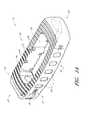
- FIG. 1Aillustrates a front perspective view of a spinal implant according to one embodiment
- FIG. 1Billustrates a rear perspective view of the implant of FIG. 1A ;
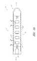
- FIG. 2illustrates a top view of the implant of FIG. 1A ;
- FIG. 3Aillustrates a side view of the implant of FIG. 1A ;
- FIGS. 3B and 3Cillustrate detailed side views of the implant of FIG. 1A ;
- FIGS. 4 and 5illustrate different side views of the implant of FIG. 1A ;
- FIG. 6Aillustrates perspective views of an implant and an insertion tool configured to engage the implant according to one embodiment
- FIG. 6Billustrates a partial top view of a spinal implant according to one embodiment
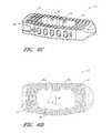
- FIG. 6Cillustrates a perspective view of a spinal implant according to one embodiment
- FIG. 6Dillustrates a top view of a spinal implant according to one embodiment
- FIG. 7Aillustrates an anterior side view of an implant within a targeted intervertebral space and secured to an insertion tool assembly, according to one embodiment
- FIG. 7Billustrates lateral side view of the implant of FIG. 7A ;
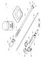
- FIG. 8illustrates two embodiments of sizing and distraction tools
- FIG. 9illustrates one embodiment of a rasping or abrading tool for use as a preparatory tool in advance of implantation of a spinal implant
- FIGS. 10A and 10Billustrate perspective views of another embodiment of a rasping or abrading tool for preparing an intervertebral space
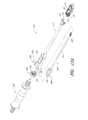
- FIG. 11illustrates a perspective view of an insertion tool assembly attached to a spinal implant, according to one embodiment
- FIG. 12Aillustrates an exploded perspective view of the insertion tool assembly and implant of FIG. 11 ;
- FIG. 12Billustrates a partial cross-sectional view of an insertion tool assembly secured to an implant, according to one embodiment
- FIG. 13illustrates a perspective view of various components of a graft fill kit, according to one embodiment
- FIG. 14illustrates an anterior side view of a fill tool assembly engaged with a spinal implant positioned within a targeted intervertebral space, according to one embodiment
- FIG. 15illustrates a syringe assembly configured for post-filling a spinal implant with graft and/or other fill materials, according to one embodiment
- FIGS. 16A-16Cillustrate various view of time-sequential steps related to positioning a syringe assembly within a fill tool assembly, according to one embodiment
- FIGS. 17A and 17Billustrates different side views of excess graft and/or other fill material that has exited the interior chamber of a spinal implant, according to one embodiment
- FIG. 18illustrates a partial cross-sectional view of an insertion tool assembly having a cannulated threaded rod and secured to an implant, according to one embodiment
- FIGS. 19 and 20illustrate different top perspective view of a spinal implant according to one embodiment
- FIG. 21illustrates a cross-sectional view of the implant of FIGS. 19 and 20 .
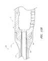
- FIG. 1illustrates one embodiment of a spinal implant 10 configured for placement between adjacent vertebrae of a patient.
- the implant 10is sized, shaped and otherwise adapted for placement with an intervertebral space along the lumbar region of spine.
- the implants and/or the methods disclosed hereincan be modified for placement in any other portion of the spine, such as, for example, the thoracic or cervical region.
- the implantcan be inserted into a target intervertebral space using a lateral delivery approach (e.g., XLIF or TLIF), an anterior approach (e.g., ALIF), a posterior approach (e.g., PLIF) and/or any other approach or technique.
- a lateral delivery approache.g., XLIF or TLIF
- ALIFanterior approach
- PLIFposterior approach
- the implant 10can include a generally rectangular shape.
- the implant 10includes another shape, as desired or required by a particular application or use.
- one or more of the implant's surfaces or sidescan be more or less tapered and/or rounded (e.g., curved, convex, etc.).
- the implantcan comprise a completely different overall shape (e.g., as viewed from the top, bottom, one or more sides, etc.), such as, for example, round, oval, elliptical, other polygonal, irregular and/or the like.
- the top surface 12 and/or the bottom surface 16 of the implant 10comprise one or more teeth 40 , protruding members and/or other features that are sized, shaped and otherwise configured to contact and engage adjacent surfaces of the vertebral endplates once the implant has been positioned within the intervertebral space.
- only the top surface 12comprises teeth or similar engagement features.
- only the bottom surface 16comprises teeth or similar engagement features.
- both the top and the bottom surfaces 12 , 16comprise teeth or similar engagement features.
- the teeth 40 or other engagement members or featurescan be distributed either completely or partially along the top surface 12 and/or bottom surface 16 of the implant 10 .
- the teeth or other engagement features 40can cover the entire or substantially the entire top and/or bottom surfaces of the implant.
- the teeth 40are located along only selected portions of the top and/or bottom surfaces, as desired or required.
- the teeth 40can extend, at least partially, from the anterior end 32 to the posterior end 36 of the implant.
- at least some of the teeth 40are generally parallel to each other.
- at least some of the teeth or similar engagement features 40 of an implantintersect with one another or are otherwise non-parallel relative to each other.
- the teeth or other engagement features 40can be symmetrically disposed along the top surface 12 and/or bottom surface 16 of the implant 10 .
- the tooth pattern along the top and/or bottom surfaces of the implantcan be asymmetrical in one or more directions.
- the teeth 40are generally straight along the middle portion of the implant 10 and generally curved (e.g., circular, oval, etc.) along each of the lateral ends 22 , 26 of the implant 10 .
- the radius of curvature of the teeth 40 along the lateral ends 22 , 26 of the implantis greater than the curvature of the teeth along the middle, center or interior portion of the implant.
- the radius of curvature of the rows of teeth 40 or other engagement featurescan increase with increasing distance from the center of the implant 10 .
- the teeth or other engagement features 40 along the top surface 12 and/or the bottom surface 16 of the implant 10can be bi-directional or unidirectional, as desired or required. Such teeth or other engagement features 40 can help ensure that the implant 10 does not migrate or otherwise undesirably move after implantation within a target intervertebral space.
- the teeth 40can assist in maintaining graft and/or other fill materials within or near the implant 10 (e.g., within an internal chamber of the implant, between the endplates of adjacent vertebral members, etc.), thereby improving and/or facilitating spinal fusion.
- the type, quantity, shapee.g., curvature along the top and/or bottom surfaces of the implant, the cross-sectional shape of the teeth, etc.
- sizee.g., height, length, etc.
- orientation, spacing and/or other details of the teeth or other engagement features 40can vary, as desired or required.
- the implant 10can include a left lateral side L and a right lateral side S.
- the teeth 40 along the top and/or bottom surfaces 12 , 16 of the implant 10are unidirectional.
- the teeth 40 along the left side L of the implantare generally curved, sloped, slanted or otherwise pointed in a first direction
- the teeth 40 along the right side R of the implantare generally curved, sloped, slanted or otherwise pointed in a second direction, which in some arrangements, is generally opposite of the first direction.
- the teeth 40 ′, 40 ′′ along the upper and/or lower surfaces 12 , 16 of the implant 10are sloped or slanted toward the horizontal center of the implant. As noted above, such a configuration can help ensure that the implant 10 engages adjacent portions of a patient's spine (e.g., vertebral endplate surfaces) and does not inadvertently migrate or otherwise move after implantation.
- such embodimentscan help ensure that the likelihood that grafting agents and/or other fill materials delivered into the interior chambers of the implant 10 undesirably escape from within or near the implant (e.g., between the upper and/or lower surfaces 12 , 16 and the adjacent endplate surfaces of the patient's vertebrae) is advantageously reduced or minimized.
- the implant 10needs to migrate or otherwise shift against the tooth grain (e.g., in one or more directions) in order to move laterally away from the target intervertebral space following implantation.
- the inwardly oriented shape of the teeth 40makes it more difficult for grafting and/or other filler materials to flow or otherwise move at or near the implant-endplate interface.
- the implant 10can include generally planar top and/or bottom surfaces 12 , 16 , at least partially along its length and/or width.
- the top surface 12 and/or the bottom surface 16 of the implant 10comprises one or more portions that are non-planar. Such non-planar areas or portions can extend only partially along the length and/or width of the implant. In other embodiments, the entire top and/or bottom surface of the implant can be generally non-planar.
- the top and/or bottom surfacescan be generally concave, rounded or otherwise curved (e.g., in the vertical direction so that the thickness of the implant varies along one or more regions of the implant).
- Such configurationscan provide for a tighter fit between the implant 10 and the adjacent endplates or other surfaces or portions of the vertebral members.
- such configurationscan help improve or enhance the spinal fusion process.
- the implantscan be generally planar but non-horizontal (e.g., from anterior to posterior ends).
- “lordotic” implant designscan include a generally higher anterior wall relative to the posterior wall.
- one or both lateral ends of an implantcan be tapered.
- a tapered lateral end 22can facilitate insertion of the device 10 within the target intervertebral space during an implantation procedure.
- the leading end 97 along the right lateral end 22 of the implant 10includes both a vertical taper and a rounded profile when viewed from the top.
- at least a portion of such a “bullet” or tapered leading lateral end of the devicecan be configured to extend outside the intervertebral space into which the implant is implanted.
- one or both lateral ends of the implantcomprise a rounded or curved contour. Such a rounded or curved contour or profile can be included in the vertical direction, in the horizontal direction or in both the vertical and horizontal directions, as desired or required.
- the exterior surface of the implant's posterior side 36can be generally flat or planar when viewed from the top. Such a design can help ensure that a proper clearance is provided between the posterior end of the implant 10 and sensitive portions of the patient's spine (e.g., nerve roots, spinal cord, etc.).
- the exterior surface of the implant's anterior side 32can include a rounded or other non-planar shape. In some embodiments, such a rounded or other non-planar shape is relatively gradual or slight.
- the exterior of the implant's lateral sides 22 , 26can be either generally planar (e.g., flat) or rounded, as desired or required. In other embodiments, the exterior shape of the implant's sides can be different than illustrated and discussed herein.
- the implant 10can include one or more insertion tool receiving ports 50 , slots and/or other features.
- a single port 50is positioned along one of the lateral ends 26 of the implant 10 .
- the port 50can be positioned along any other portion of the device. The location of the port 50 can depend, at least in part, on the desired method by which the implant 10 will be inserted into the patient's spine (e.g., laterally, anteriorally, posterially, etc.).
- the port 50is positioned along a lateral end 26 , primarily because the implant 10 is designed to be inserted into the target intervertebral space laterally. Therefore, in other configurations, an insertion tool receiving port 50 can be included along the anterior side 32 , posterior side 36 and/or any other portion of the implant.
- the insertion tool receiving port 50is configured to releasably engage a corresponding insertion tool using a threaded connection.
- the port 50can include internal threads that are sized, shaped and otherwise adapted to match external threads of an insertion tool 300 ( FIG. 6A ).
- other types of connection features or devicesare used to releasably secure an insertion tool to the implant, such as for example, a press-fit or friction fit connection, a snap-fit connection, a tabbed connection, any other standard or non-standard coupling and/or the like.
- the port 50also serves as an inlet into the implant's interior chambers through which grafting and/or other fill materials can be selectively delivered within the implant.
- a single port 50is used both an implant delivery mechanism and a graft material passage.
- the port 50comprises one or more valves (e.g., check valve, other one-way valve, etc.), other flow-regulating devices or features and/or one or more other sealing members to help prevent or reduce the likelihood of the inadvertent loss of grafting and/or other fill materials from within the interior of an implant through such a port 50 .
- the port 50can be threaded or non-threaded, as desired or required.
- the portcomprises one or more other engagement or other features, such as for example, alignment slots, tabs, teeth, other protruding members and/or the like. Such features can extend inwardly (e.g., in the direction of the port's opening) from the wall or other surface defining the port 50 .
- the shape (e.g., cross-sectional shape) of the portis generally circular.
- the portcan include one or more other shapes, such as, for example, oval, elliptical, square, rectangular, other polygonal, irregular and/or the like.
- the threaded port 50 along a lateral end 26 of the implantis configured to pass at least partially through the implant's lateral wall 98 .
- the port 50passes through the entire lateral wall 98 and extends into one or more internal chambers 70 , cavities or other openings of the implantable device 10 .
- the port 50is sized to permit a catheter, syringe, tubing, other tube, conduit and/or other delivery device to be passed therethrough.
- a catheter or other delivery tube or devicecan be sized and configured to allow grafting and/or other materials to be selectively injected or otherwise administered into one or more chambers of the implant.
- the portis sized to permit a catheter or other tube of size French 12 or French 15 (e.g., per the standard French gauge scale) to be passed therethrough.
- the port 50can include a minimum inside diameter of about 4 mm or about 5 mm. In other embodiments, however, the port 50 can be sized, shaped and otherwise configured to permit the passage of larger catheters, tubes or other conduits therethrough.
- an implantis configured to permit a catheter, tube or other conduit having an outer diameter as large as about 5 mm through 8 mm (e.g., approximately 5 mm, 5.5 mm, 6 mm, 6.5 mm, 7 mm, 7.5 mm, 8 mm, sizes between the foregoing, etc.) to pass through its port 50 .
- the portis sized and shaped to allow conduits having an outer diameter larger than 8 mm (e.g., approximately 8 mm, 8.5 mm, 9 mm, larger than about 9 mm, etc.) to pass therethrough.
- the threaded port 50 or access holecomprises an M6 ⁇ 1.0 configuration.
- the portcan comprise a nominal diameter that is greater than or less than about 6 mm, such as, for example, approximately 4 mm, 5 mm, 7 mm, 8 mm, 9 mm, 10 mm, greater than 10 mm, sizes between the foregoing values, etc.).
- the thread along the inside of the portcan differ from that in an M6 ⁇ 1.0 configuration, as desired or required.
- the thread type, pattern, height and/or other characteristics of the threadcan vary.
- the spinal implants disclosed herein or equivalents thereofcomprise a generally closed structure along their sides.
- the only openings along the outer sidewalls (e.g., lateral, posterior, anterior) of an implantare one or more ports 50 (e.g., used to engage the implant with a delivery tool and/or used to pass a graft delivery tube to the interior of the implant) and/or one or more openings that permit excess grafting materials to exit an interior chamber or other cavity of the implant (e.g., openings 60 along the anterior side wall of the implant, as illustrated in FIG. 3A ).
- the port 50 or other openings through a wall of the implantis configured to be as large as possible for a given implant. This can permit a larger device (e.g., catheter, syringe, tubing, other conduit or device, etc.) to be positioned therein.
- the port 50can be advantageously adapted to receive a tube that is configured to transfer grafting and/or other fill materials from a syringe (or other supply source) to the interior of the implant. Therefore, in such embodiments, the inside diameter (or other cross-sectional clearance dimension) of the port 50 is slightly larger than the outer diameter (or other outer dimension) of the fill catheter or other conduit.
- the portcomprises a diameter of approximately 6 mm to 8 mm (e.g., about 6 mm, 6.5 mm, 7 mm, 7.5 mm, 8 mm, diameters between the foregoing values, etc.).
- the diameter or other cross-sectional dimension of the port 50can be smaller than about 6 mm (e.g., approximately 4 mm, 4.5 mm, 5 mm, 5.5 mm, 5.9 mm, diameters between the foregoing values, etc.) or larger than about 8 mm (e.g., approximately 8.1 mm, 8.5 mm, 9 mm, 9.5 mm, diameters between the foregoing values, larger than about 9.5 mm, etc.), as desired or required.
- a target diameter or other cross-sectional dimension of the port 50is generally maintained, irrespective of the size of the implant (e.g., 6 mm, 8 mm, 10 mm, 12 mm tall implants). This can help ensure that a surgeon or other clinician can insert a desired fill tube or other conduit within an interior of an implant (e.g., to delivery grafting and/or other fill materials during a post-fill procedure). Accordingly, as noted herein with reference to the embodiments illustrated in FIGS.
- one or more implant walls through which the port 50 passesmay need to be reinforced or otherwise strengthened to accommodate a desired port diameter (e.g., 6 mm, 8 mm, etc.) in light of the implant's thickness.
- a larger fill tube or conduitcan be advantageously positioned through such a port. Accordingly, the friction associated with passing grafting and/or other fill materials through the fill tube can be reduced. This allows for less strenuous delivery of grafting and/or other fill materials into the interior of an implant (e.g., during a post-fill procedure). Accordingly, the surgeon or other clinician performing a fill procedure can more easily deliver the necessary materials through the fill tube.
- the ratio of the port diameter (or other port opening size) to the height of the implant wall through which the port is locatedis between about 0.4 and about 0.9 (e.g., approximately 0.4, 0.45, 0.5, 0.55, 0.6, 0.65, 0.7, 0.75, 0.8, 0.85, 0.9, ratios between the foregoing values, etc.), depending on the size of the implant.
- the port diameteris approximately 6 mm and the height of the corresponding implant wall is 8 mm, 10 mm, 12 mm or the like.
- the ratiocan be approximately 0.75, 0.6, 0.5 and/or the like.
- the ratio of the port diameter (or other port opening size) to the height of the implant wall through which the port is locatedis at least about 0.5, 0.55, 0.6, 0.65, 0.7, 0.75, 0.8, 0.85, 0.9, greater than about 0.9 and/or the like.
- the area of the port 50is at least about 10%, 15%, 20%, 25% or 30% of the overall area of the wall (e.g., lateral implant wall) through which the port is positioned.
- the port areacan be smaller than about 10% or greater than about 25% of the overall area of the wall through which the port is positioned, as desired or required.
- the implants disclosed hereincan be provided in a variety of shapes, sizes and configurations in order to better accommodate the intervertebral spaces into which they will be inserted and secured.
- the various types of implants that are supplied to a surgeon or other cliniciancomprise an identical port 50 (e.g., having an identical diameter, shape, thread pattern, etc.), regardless of the actual size, shape and other details of the devices. Accordingly, a surgeon or other clinician can use a single insertion tool and/or a single set of other instruments to engage and manipulate the various types of implants provided.
- the port 50can also be used as a passageway for a catheter, syringe, tube or other conduit.
- Such conduitscan be passed through the port 50 to selectively deliver grafting agents, other filler materials and/or any other device or substance within an interior chamber, cavity or other portion of the implant.
- the passage of catheters and/or other conduits through the portis performed after the implant has been securely positioned within a target intervertebral site and after one or more delivery tools have been detached from the implant.
- the graft delivery catheter or other conduitcan be passed through the port 50 to reach an interior portion of the implant while an implant delivery tool is secured to the port.
- a catheter or conduitcan be passed through an interior lumen or other passage of a cannulated implant delivery tool.
- one or more portions of smaller implantsmay be reinforced with additional material and/or other support along or near an area surrounding the port 50 .
- additional implant material 13e.g., PEEK, other polymeric or other material, etc.
- PEEKpolymeric or other material, etc.
- additional material or other reinforcement 13 along the top and/or bottom surface of the implant 10can provide the requisite resistance to the forces and moments to which the implant may be subjected during delivery and/or use.
- additional reinforcing material 13can be positioned within at least of the grooves that help define the teeth 40 or other engagement features of the implant 10 .
- the depth and general configuration of the teeth 40 along such reinforced areasmay vary from adjacent areas of the implant.
- the implant 10can include one or more additional features that facilitate engagement with a corresponding insertion tool.
- the implantcomprises two recesses or slots 28 along one of the lateral ends 26 (e.g., along the lateral end that includes the insertion tool receiving port 50 ).
- Such recesses or other features 28can be sized, shaped, positioned, spaced, oriented and/or otherwise adapted to align and mate with corresponding wings, tabs or other portions of an insertion tool.
- the recesses, slots and/or other engagement features 28can help a surgeon or other clinician to manipulate (e.g., rotate) the implant during surgery or other procedure involving moving or repositioning the implant. Further, such engagement features 28 can help ensure that the corresponding implant insertion tool (and/or graft fill tool, as discussed in greater detail herein) is properly positioned relative to the implant.
- the spinal implant 10can include one or more internal chambers 70 .
- the implantcomprises only a single chamber.
- the implantcomprises two or more chambers.
- such internal chambers 70can extend across the entire implant depth (e.g., from the top surface 12 to the bottom surface 16 ) and across a majority of the implant's length and width.
- the chamber 70spans approximately 60-70% of the implant length and width.
- the chamber 70can extend less than about 60% of the implant length and/or width (e.g., approximately 30%, 35%, 40%, 45%, 50%, 55%, 60%, less than 30%, percentages between the aforementioned values, etc.), or more than about 70% of the implant length and/or width (e.g., approximately 70%, 75%, 80%, 85%, more than about 90%, percentages between the aforementioned values, etc.), as desired or required by a particular application or use.
- 60% of the implant length and/or widthe.g., approximately 30%, 35%, 40%, 45%, 50%, 55%, 60%, less than 30%, percentages between the aforementioned values, etc.
- more than about 70% of the implant length and/or widthe.g., approximately 70%, 75%, 80%, 85%, more than about 90%, percentages between the aforementioned values, etc.
- an implantcomprises two or more chambers.
- the implants illustrated in FIGS. 1A-5can include one or more dividing walls (not shown) that extend across the chamber 70 generally between the anterior and posterior walls 92 , 94 .
- Such dividing walls or other separatorswhich may be integrally formed with adjacent portions of the implant, can effectively create two or more sub-chambers or cavities in the implant.
- such chambers or sub-chamberscan be of equal or different shape and/or size.
- one or more openingscan be included in the dividing wall or other separators to permit the chambers to be in fluid communication with one another. This may be particularly important when the filling the implant with grafting and/or other materials (e.g., to help ensure that such fill materials are delivered into all of the chambers).
- a spinal implant 10can include one or more openings 60 that extend through its anterior wall 92 , but no openings along its posterior wall 94 .
- the openings 60can be in fluid communication with the implant's chamber(s) 70 .
- excess grafting and/or other fill materials delivered into the chamber(s) 70e.g., through a fill port 50 and/or other opening in the implant
- the passage of fill materials along the posterior side of the implantcan be generally reduced or prevented.
- a majority (or almost all) of excess grafting agent and/or filler material delivered within such an implantcan be configured to exit the interior of the implant through the anterior openings 60 .
- more than approximately 70% (e.g., more than about 70%, 75%, 80%, 85%, 90%, 95%, etc.) of excess fill materials delivered into an implantexit through the openings 60 .
- thiscan advantageously help prevent or reduce the likelihood of migration of grafting and/or other fill materials toward nerve roots, spinal cord and other sensitive regions of the spine.
- an implant 10can include a total of five openings 60 that are generally equally sized and equally spaced apart from each other along the anterior wall.
- the openings 60comprise an oval shape or a generally rectangular shape with rounded corners.
- the openings 60can include any other shape (e.g., circular, square, rectangular, other polygonal, irregular, etc.).
- the quantity, spacing, relative size, orientation and/or other characteristics of the openings 60can be different than illustrated and discussed herein.
- additionale.g., six, seven, eight, nine, ten, more than ten, etc.
- fewer openingse.g., four, three, two, one
- the implant 10can comprise one or more internal prongs or other protruding members 74 that extend into the chamber 70 .
- such prongs 74can be formed as a unitary structure with adjacent portions of the implant.
- the internal prongs 74can be separate members that are subsequently secured to the implant using one or more connection devices or methods, such as for example, screws, rivets, other fasteners, adhesives and/or the like.
- the prongs 74can be positioned along various locations of the implant's interior surface. For example, in some embodiments, as illustrated in FIGS.
- the prongsare positioned along various lateral portions near the top and/or bottom of the implant.
- the internal prongs or other engagement membercan be situated along any other portion or area of the chamber 70 , either in addition to or in lieu of the top and/or bottom portions of the implant.
- the prongs 74are directed toward the interior chamber or cavity 70 of the implant 10 .
- the prongs 74can be aligned generally perpendicularly relative to the interior vertical wall that defines the chamber 70 and from which the prongs extend inwardly.
- one or more of the prongscan be positioned along a line that is offset from the lengthwise or widthwise centerline of the implant 10 .
- one or more prongs 74are offset by angle P relative to the widthwise centerline W of the implant 10 .
- such an angle Pis approximately 20-25% (e.g., about 20%, 25%, 30%, etc.).
- the prongs 74can comprise a generally conical, wedge-like, truncated cone-like, triangular, pyramid-like and/or any other shape (e.g., when viewed from the top).
- shape, size, spacing, orientation and/or other characteristics of the prongs 74can be different than illustrated and discussed herein.
- prongs or other features 74can help ensure that grafting agents and/or other fill materials are properly retained within the internal chamber(s) 70 of the implant 10 .
- a solid graft, a porous foam structure, a sponge and/or other solid or non-flowable memberis positioned within the chamber 70 of the implant, either before or after implantation into a patient.
- the prongs 74can help engage such items and maintain them within the implant.
- the prongs 74help secure grafting and/or other filler materials within a chamber 70 of the implant only after such materials have become adequately hardened or solidified.
- the thickness (e.g., vertical height) and width (e.g., anterior-posterior distance) of the implant 10can be generally consistent throughout its entire length.
- one lateral end of the implantcan comprise a larger thickness than the opposite lateral end.
- Such arrangementscan be advantageously used when inserting an implant along to a lordotic portion of the spine.
- the height difference between opposing ends in such lordotic implantscan differ by about 2 mm.
- the height differenceis less or greater than about 2 mm (e.g., approximately 0.5 mm, 1 mm, 1.5 mm, 2.5 mm, 3 mm, 3.5 mm, 4 mm, greater than 4 mm, distances between the aforementioned values, etc.), as desired or required for a particular patient or fusion procedure.
- 2 mme.g., approximately 0.5 mm, 1 mm, 1.5 mm, 2.5 mm, 3 mm, 3.5 mm, 4 mm, greater than 4 mm, distances between the aforementioned values, etc.
- the horizontal width of the implant's lateral walls 96 , 98can be configured to enhance the implant's ability to withstand the bearing forces, moments and other loads to which it will be subjected once properly implanted into a patient's spine.
- the lateral walls 96 , 98 of the implant 10can be configured to align with portions B of the adjacent vertebrae V through which the highest concentration of bearing forces are transferred to the implant 10 .
- such high bearing load areas or portions Bare situated near the lateral or circumferential ends of the vertebrae V.
- the endplates of the vertebrae Vmove further away from the adjacent intervertebral space near the center of the vertebral body. Thus, most of the bearing load created by the adjacent vertebrae V is expected to be concentrated toward the peripheral ends of the implant 10 .
- the implant 10can include lateral walls 96 , 98 that are generally reinforced and otherwise adapted to safely handle the bearing loads imposed upon the implant following implantation.
- the lateral walls 96 , 98can be wider (e.g., horizontally) than the anterior and/or posterior walls 92 , 94 of the implant.
- the horizontal length (e.g., along the longer axis of the implant) of each of the lateral walls 96 , 98is at least about two times greater than the horizontal width of the anterior or posterior wall.
- the horizontal length of one or both of the lateral walls 96 , 98is approximately at least two, three, four or more than four times the horizontal width of the anterior wall or the posterior wall of the implant.
- the horizontal length of one or both of the lateral walls 96 , 98is approximately 10 to 20% (e.g., about 10%, 12%, 14%, 16%, 18%, 20%, percentages between the foregoing values, etc.) of the overall horizontal length of the implant (e.g., along the longer axis of the implant).
- the horizontal length of the one or both of the lateral walls 96 , 98can be greater than about 20% or less than about 10% of the overall horizontal length of the implant 10 , as desired or required. Consequently, one or both of the implant's lateral ends 22 , 26 can be configured to better withstand the bearing forces and moments to which the implant it will be subjected once inserted and secured within a targeted intervertebral space of the patient's spine.
- a spinal implantis sized to generally span across the entire width of the adjacent vertebral members V.
- the lateral walls of the implantcan be generally aligned with the load bearing portions of the inferior and superior vertebral members.
- the implantcontacts the adjacent vertebral members primarily or only along the lateral ends of the implant.
- portions of the implant that are interior to the lateral ends of the implantare configured to encounter less or no forces from the adjacent vertebral members.
- the implant 10comprises one or more radio-opaque markers 80 .
- markers 80can facilitate a surgeon or other clinician to properly position the implant within the target intervertebral space, especially when minimally invasive surgery is utilized.
- the implant 10can include a total of three tantalum or other types of radiopaque markers 80 ′, 80 ′′.
- two markers 80 ′are located at or near the lateral ends 22 , 26
- a third marker 80 ′′is located at or near the horizontal center of the implant 10 .
- the lateral or horizontal location of the middle marker 80 ′′is exactly between the two lateral markers 80 ′′.
- the quantity, type, location, orientation, spacing and/or other details of the markerscan be varied, in accordance with the specific requirements of an application or use.
- the posterior wall 94 of the implant 10can include a bump or other reinforced region 95 in order to accommodate the center radio-opaque marker 80 ′′.
- bumps 95 or similar featurescan advantageously improve the implant's strength and/or other structural characteristics.
- the implants disclosed hereincan include one or more materials.
- the implantscomprise polyether etherketone (PEEK), other radiolucent materials, other thermoplastics, metals, alloys and/or any other materials having the desired structural (e.g., rigidity), mechanical, chemical and thermal resistance and/or other properties.
- PEEKpolyether etherketone
- other radiolucent materialsother thermoplastics, metals, alloys and/or any other materials having the desired structural (e.g., rigidity), mechanical, chemical and thermal resistance and/or other properties.
- the size of the implantcan be selected based, at least in part, on the patient's weight, height, age, the amount of intervertebral distraction that the implant should provide and/or any other factor or consideration.
- the implantis precisely selected based on the size of the patient's intervertebral space into which the implant will be placed.
- the vertical height of the implantcan vary between approximately 8 and 14 mm (e.g., 8 mm, 10 mm, 12 mm, 14 mm, values between such ranges, etc.).
- the vertical height of the implantcan be consistent from the anterior end to the anterior end.
- the vertical height of the implantcan vary in one or more horizontal directions (e.g., anterior-posterior direction, lateral direction, etc.).
- the implantincludes a concave or other non-planar (e.g., domed, curvate, etc.) upper surface and/or lower surface.
- a concave or other non-planar (e.g., domed, curvate, etc.) upper surface and/or lower surfacecan help provide improved contact between the implant and the endplate surfaces of the adjacent vertebrae.
- the height of the implantcan vary along the anterior-posterior direction.
- the vertical height of the anterior wall of the implantis approximately 2 mm higher than the vertical height of the posterior wall.
- any of the fusion implants disclosed hereincan have vertical dimensions that vary along their longitudinal direction.
- lordotic implantscan be provided, such as, for example, 8 mm by 10 mm (e.g., posterior height by anterior height), 10 mm by 12 mm, 12 mm by 14 mm implants and/or the like.
- the implantcan be provided in a variety of horizontal dimensions in order to better accommodate the targeted intervertebral space into which the implant will be inserted and secured.
- the length of the implante.g., from one lateral end to the other
- the implantis provided in a variety of different lengths, such as, for example, 40 mm, 45 mm, 50 mm, 55 mm, 60 mm, lengths between the foregoing values, etc.
- the length of an implantcan be greater than 60 mm or smaller than 40 mm, as desired or required.
- the width (e.g., the distance between the anterior and posterior ends) of the implantcan vary, both from implant to implant and within a specific implant design.
- the width of the implantis between about 19 mm and 21 mm.
- the widthcan vary along an implant's length. In some embodiments, such a variation in width results from rounded or curved anterior and/or posterior surfaces.
- the implantcomprises a width of approximately 21 mm at its longitudinal center (e.g., at or near the location of the middle marker 80 ′′ is located in the arrangement depicted in FIG. 2 ) and a width of approximately 19 mm at or near the lateral ends 22 , 26 .
- the implantscan include any other shape, size or orientation, irrespectively of the specific examples provided herein.
- the initial surgical steps in preparing a patient for a spinal fusion procedurecan include, among other things, making an incision along the patient's skin and accessing a targeted region of the spine (e.g., lumbar region) using one or more dilators, retractors and/or other instruments or tools.
- a targeted region of the spinee.g., lumbar region
- one or more preparatory stepsmay be necessary or recommended prior to delivery of the implant within the patient's anatomy.
- at least some of the native disc materialcan be removed in order to provide the necessary space for the subsequent insertion of the implant.
- a distraction toolis used to separate the vertebrae between which the implant will be positioned.
- surgeon or other clinician performing the proceduremay choose to size the target intervertebral space prior to implantation. For example, such a step can be performed in order to more accurately select a properly sized implant.
- a surgeonmay choose to prepare one or more native surfaces of the vertebrae that will be adjacent to the implant. For instance, one or more coarsening or abrading tools can be used to selectively roughen one or more portions of the vertebral endplates adjacent to the implant. Under certain circumstances, such a roughening step can promote healing and can accelerate the fusion process following delivery of the implant within the spine.
- FIG. 8illustrates two different arrangements of a distraction and sizing tool 400 A, 400 B that can be used in advance of the delivery of an implant during a spinal fusion procedure.
- the distraction and sizing tool 400 A, 400 Bcan include a proximal handle 410 A, 410 B (which is only partially depicted in FIG. 8 ) and a distal head 420 A, 420 B.
- the two tools 400 A, 400 Bare substantially similar to each other in overall design; however, their distal heads 420 A, 420 B vary in size (e.g., vertical thickness, length, etc.).
- a plurality of such distraction and sizing toolsmay be provided to a surgeon in order to allow him or her to determine what type of implant should be inserted into targeted intervertebral space.
- Such tools 400 A, 400 Bcan also be used to precisely distract or separate adjacent vertebrae in preparation for implantation.
- the sizing and distraction tool 400 A, 400 Bcomprises stainless steel, other metals or alloys and/or one or more other rigid material that are adequate for insertion into a patient's anatomy and configured to withstand the anticipated forces, moments and/or other conditions (e.g., pH, temperature, etc.) to which they will be subjected.
- the sizing and distraction tool 400 A, 400 Bcan include a baseline marker 430 A, 430 B at or near the distal end of the head 420 A, 420 B.
- the surgeoncan insert the tool's head 420 A, 420 B within the target intervertebral space and advance the tool (e.g., under the guidance of x-ray, ultrasound, fluoroscopy and/or other imaging technology) until the baseline marker 430 A, 430 B exactly or approximately aligns with the peripheral distal edge of the adjacent vertebral bodies.
- the surgeoncan use the proximal markings 440 A, 442 A, 444 A, 446 A, 448 A to determine the appropriate length of the intervertebral space.
- the lengthcan be determined based on the proximal marking that is closest to the peripheral proximal edge of the adjacent vertebral bodies.
- the markings 440 A, 442 A, 444 A, 446 A, 448 Acan be visualized using one or more imaging technologies to determine the proper implant size for the targeted intervertebral space.
- the surgeoncan attempt to position tools 400 A, 400 B of varying head thickness into a targeted intervertebral space in order to determine a desired implant height.
- the sizing and distraction tool 400 A, 400 Bcan be used to select a well-suited implant for insertion into the patient's spine.
- such a tool 400 A, 400 Bcan be used to create a desired level of vertical distraction within the targeted intervertebral space, especially if the adjacent vertebral bodies are undesirably close to one another (e.g., due to severe disc degeneration and/or disease).
- FIG. 9schematically illustrates one embodiment of a shaver 500 configured to selectively rasp, abrade and/or otherwise compromise or remove tissue.
- the shaver 500is inserted into an intervertebral space to remove disc tissue and/or prepare the vertebral endplate surfaces for the subsequent delivery of a spinal implant.
- the shaver 500can comprise an abrading assembly 520 positioned along a distal end of a longitudinal shaft 510 .
- the abrading assembly 520can include a center or main portion 534 located between a pair of tapered outer portions 530 A, 530 B.
- the center portion 534comprises one or more abrading members 540 that are adapted to contact and at least partially remove, abrade or otherwise affect tissue.
- the abrading member 540can help remove native disc tissue and/or attack the endplate wall in preparation for the subsequent implantation of the fusion device.
- the shaver 500comprises tapered or lower profile outer portions 530 A, 530 B so as to reduce or prevent damage to the peripheral bearing areas B of the vertebral members V (see FIG. 7A ). By avoiding or reducing the likelihood of damage to these native load bearing portions B of adjacent vertebrae, the structural integrity of the patient's spine, and thus the fusion procedure, can be maintained.
- FIGS. 10A and 10BA different embodiment of a shaver instrument 550 is schematically illustrated in FIGS. 10A and 10B .
- the shaver 550comprises a main portion 560 that is shaped, sized and otherwise configured for delivery into a targeted intervertebral space.
- the upper and lower surfaces of the main portionmay or may not include teeth or other engaging features or members.
- the main portion 560includes a central chamber or other opening 570 that generally extends from the top to the bottom surface of the main portion 560 .
- an access port or opening 564can provide access from a lateral side of the main portion 560 to the interior of the central chamber 570 .
- An abrading assembly 590can be positioned along the distal end of an elongated member 580 .
- the elongated member 580can be sized, shaped and otherwise adapted for passage through the access port 564 of the main body.
- the abrading assembly 590can be configured for placement within the chamber 570 of the main portion 560 .
- the abrading assembly 590is configured for selective movement within the central chamber 570 as the elongated member 580 is rotated about a longitudinal axis 582 .
- the abrading assembly 590can comprise a generally horizontal configuration. As shown, the abrading assembly 590 can include one or more lateral wing portions 592 positioned on either side of the elongated member 580 . In some embodiments, the outer surface 594 of each wing portion 592 can include one or more abrasive members or features 596 that are adapted to contact and at least partially remove or damage tissue. In some arrangements, the abrading assembly 590 is fully retained within the central chamber 570 when in the illustrated low profile or stowed orientation. Thus, the shaver 550 can be delivered to the patient's spine without interference by the abrading assembly 590 .
- the surgeon or other cliniciancan selectively rotate the elongated member 580 to move the distal wing portions 592 toward the adjacent tissue (e.g., native disc tissue, endplate surfaces, etc.).
- the adjacent tissuee.g., native disc tissue, endplate surfaces, etc.
- continued and repetitive rotation of the abrading assembly 590can cause a desired amount of abrasion to the adjacent vertebral members in preparation for delivering the implant device to the intervertebral space.
- the central chamber 570 of the shaver 550generally aligns with a central portion of the adjacent vertebrae between the peripheral bearing areas B ( FIG. 7A ).
- FIG. 11illustrates a perspective view of a spinal implant 10 , identical or similar to those disclosed herein, secured to a distal end of an insertion tool assembly 300 according to one embodiment.
- An exploded view of the insertion tool assembly 300 of FIG. 11is provided in FIG. 12A .
- the insertion tool 300can include an outer elongated member 310 having a distal end 312 that is adapted to releasably engage a spinal implant 10 .
- the distal end 312 of the outer elongated member 310comprises a pair of wings or tabs 314 that are sized, shaped and otherwise configured to engage corresponding recesses or slots 28 ( FIG. 1A ) of an implant 10 .
- the outer elongated member 310can include an inner passage 316 that extends from the proximal end 320 to the distal end 312 of the insertion tool assembly 300 .
- the outer elongated member 310is cannulated.
- the proximal portion 320 of the assembly 300can include a handle 322 and a flared end 328 .
- the outer elongated member 310includes one or more windows 324 at or near the handle. As discussed in greater detail below, such a window can permit access to a thumbwheel or other movable control member that daylights or is exposed through the window 324 .
- the outer elongated member 310can be configured to slidably receive a threaded rod 340 within its inner passage or opening 316 .
- the threaded rod 340comprises a main elongated portion 344 having a threaded distal end 346 .
- the threaded distal end 346can be shaped, sized and otherwise adapted to engage a corresponding port 50 of a spinal implant ( FIG. 1A ).
- FIG. 12BA partial cross-sectional view of such threaded engagement between the distal end 346 of the rod 340 and the port 50 of the implant 10 is illustrated in FIG. 12B .
- the threaded distal end 346can extend through the distal end of the opening 316 , generally between the wings or tabs 314 of the outer member 310 .
- the proximal end of the threaded rod 340can comprise a generally cylindrical thumbwheel 348 that includes a larger diameter than the adjacent main elongated portion 344 .
- at least a portion of the thumbwheel 348is accessible through the window(s) 324 of the outer elongated member 310 when the insertion tool assembly 300 is properly assembled for use.
- a surgeon or other cliniciancan selectively rotate the thumbwheel 348 while grasping the insertion tool assembly 300 to either engage or release the implant from the assembly's distal end.
- the thumbwheel 348can include a plurality of longitudinal grooves 349 and/or other features that can facilitate rotation of the threaded rod relative to the outer elongated member 310 .
- a hammer or strike pad 360can be secured to the proximal end of the outer elongated member 310 once the threaded rod 340 has been properly positioned therein.
- the hammer pad 360includes distal threads 366 or other engagement features that are configured to engage corresponding threads or features of the outer elongated member 310 .
- the hammer pad 360can be releasably attached to the outer elongated member 310 .
- a spinal implant 10can be secured to the distal end 312 of the insertion tool assembly 300 .
- the threaded distal end 346 of the rod 344can threadably secure to the access port or opening 50 along a lateral end of the implant 10 .
- the tabs or wings 314 of the outer elongated membercan engage corresponding recesses 28 of the implant 10 .
- the insertion tool assembly 300 and the implant 10can include one or more other types of corresponding mating or engaging features or members, either in lieu of or in addition to those disclosed herein.
- the surgeon or other cliniciancan drive the implant 10 into the targeted intervertebral space.
- the insertion tool assembly 300can be advanced into the anatomy (e.g., against any resistive forces) by impacting the proximal end of assembly 300 with a slap hammer assembly 380 , a mallet or any other tool or instrument.
- the implantation procedurecan be performed under real-time visualization in order to ensure that the implant is properly advanced and positioned.
- the various components of the insertion tool assembly 300 disclosed herein, including the outer elongated member 310 , the threaded rod 340 and the hammer pad 360 ,can comprise one or more rigid materials, such as, for example, hardened stainless steel, other types or grades of steel, titanium, other metals or alloys, composites, other natural or synthetic materials and/or the like. Such components can be reusable (e.g., sterilizable) or disposable, as desired or required.
- the internal chamber(s) of the implantcan be at least partially filled with one or more grafting materials, other fill materials and/or the like.
- the various materials that can be delivered to the internal chamber(s) of an implantinclude, but are not limited to: bone forming cells, demineralized bone matrix (DBM), bone morphogenetic protein (BMP), collagen matrix, bone cement, other flowable grafting agents or materials, flaky or other non-flowable grafting agents or materials, other biological or non-biological materials or substances and/or any other grafting or filler material.
- the implantis at least partially prefilled with one or more grafting agents, other fillers and/or any other material or item prior to implantation.
- a sponge, foam, other porous structure or member or other absorbent memberis positioned within the implant's chamber prior to advancing the implant within the anatomy.
- Such an absorbent membercan initially include one or more graft materials and/or can be configured to absorb or otherwise retain graft materials that are delivered into the chamber after the implant has been positioned with the targeted intervertebral space.
- one or more graft materials and/or other fill materialscan be provided in solid or partially-solid form within the implant's internal chamber(s) prior to implantation.
- one or more internal prongs 74can be used to securely maintain such items or materials within the implant.
- prongs or other protruding membersare configured to engage and retain materials contained within an internal chamber or cavity of the implant after such materials have at least partially solidified or cured.
- a fill tool assemblyis subsequently inserted into anatomy in order to engage the implant and selectively deliver graft and/or other types of materials into the implant's internal chamber.
- a fill tool assemblycan include a catheter, tube, syringe and/or other conduit that is sized, shaped and otherwise adapted to be positioned through one or more ports of the implant.
- a port 50can be identical to the port that is also used to secure the implant to the distal end of a delivery tool during delivery of the implant within the patient's anatomy.
- a kit 600that comprises, among other things, a fill tool assembly 610 is illustrated in FIG. 13 .
- a fill kit 600can include one or more of the following items: a fill tool assembly 610 , a coupler 640 , a syringe assembly S, a mixing tray T, a container of graft or other fill material G and/or the like.
- a fill tool assembly 610can include one or more of the following items: a fill tool assembly 610 , a coupler 640 , a syringe assembly S, a mixing tray T, a container of graft or other fill material G and/or the like.
- the graft and/or other types of fill materialscan be selected by the surgeon or other clinician according to a desired or required protocol or procedure.
- the mixing tray Tcan be used to combine, mix, dilute or otherwise process the various graft and/or other fill materials that will be selectively transferred within or near the implant.
- the various components included in the kit 600can be disposable or reusable, as desired or required.
- such componentscan include one or more rigid, semi-rigid and/or flexible materials, including metals or alloys (e.g., stainless steel), polymeric or thermoplastic materials, rubber or other elastomeric materials, composites, other natural or synthetic materials and/or the like.
- the fill tool assembly 610includes an elongated cannulated shaft 614 that terminates in a distal end 620 .
- the distal end 620can include a discharge opening 616 that is in fluid communication with the internal passage of the shaft 614 .
- the distal end 620 of the fill tool assembly 610can comprise one or more tabs or wings 622 that are sized, shaped and otherwise configured to engage corresponding recesses 28 or other features of the implant 10 ( FIG. 1B ). Although such tabs 622 , wings or other alignment features are not necessary, they can provide assurance that the fill tool assembly has been properly positioned relative to the implant in anticipation of the subsequent filling steps.
- the proximal end 630 of the fill tool assembly 610can include a handle.
- the proximal end 630comprises a number of ring shaped portions.
- FIG. 14One embodiment of a fill tool assembly 610 aligned and engaged with an implant 10 that has been properly secured within a targeted intervertebral space is illustrated in FIG. 14 .
- graft or other fill materialscan be loaded into a syringe 650 of a syringe assembly S.
- the syringe 650can include a barrel portion 652 into which the graft and/or other fill materials are placed.
- the syringe 640can include a plunger 658 that can be selectively advanced within the barrel 652 in order to help urge the graft and/or other fill materials out of the distal exit opening 654 of the syringe 650 .
- the syringecan include a pair of grasping members 656 to facilitate handling and manipulation during use.
- one or more mechanical toolscan be used to assist the surgeon or other clinician in slidably displacing the plunger or similar movable member within the barrel.
- the use of such syringe/plunger configurationscan be particularly helpful when transferring graft and/or other fill materials that are relatively thick, dense, concentrated, viscous or otherwise difficult to move.
- a discharge coupling 660can be used to attach the distal end of the syringe 650 to a length of flexible catheter, tubing or other conduit 670 .
- the tubing 670is cable-lined and/or otherwise reinforced to reduce the likelihood of kinking during use.
- Such cable-lined tubingcan also be used to confirm its location within the anatomy during use, as the cable lining can be visualized using one or more visualization technologies.
- the coupling 600can be permanently or removably secured to the syringe 650 and/or the tubing 670 using one or more types of connection methods or devices, such as, for example, luer connections, threaded connections, friction fit or press fit connections, other types of fasteners, adhesives and/or the like.
- connection methods or devicessuch as, for example, luer connections, threaded connections, friction fit or press fit connections, other types of fasteners, adhesives and/or the like.
- the flexible tubing or other conduit 670 and/or other components of the syringe assembly Sretain the same characteristics, irrespective of the type of spinal implant that will be filled.
- the length of the tubing 670 and couplingcan be maintained consistent or substantially consistent in all kits 600 .
- a coupler 640can be used to ensure that a volume of graft and/or fill material is adequately, accurately and consistently delivered to the implant.
- the coupler 640can be configured to receive and engage the proximal end of the fill tool assembly 610 through its distal opening 642 . Likewise, the coupler 640 can receive and engage a distal end of the syringe assembly S through its proximal opening 644 . In some arrangements, the coupler 640 is selected based on the size and/or type of spinal implant that will be filled. Such a configuration can help ensure that the distal end of the syringe assembly's tubing, catheter or other conduit 670 is properly positioned within the implant's internal chamber at the initiation of the graft filling stage.
- the coupler 640is generally longer for the filling of smaller (e.g., shorter) implants, and generally shorter for the filling of larger (e.g., longer) implants.
- a kit 600can be provided with a number of differently sized couplers 640 from which a clinician can choose (e.g., depending on the type of implant that will be at least partially filled).
- the couplers 640can include a size identifier 646 , such as, for example, the length of the implant to be filled.
- FIGS. 16A-16Cillustrate three time-sequential steps performed in preparation for a post filling procedure, in which grafting and/or other fill materials are delivered within an interior portion of a spinal implant following implantation.
- the fill tool assembly 610has been properly secured to the implant 10 .
- the tabs or wings along the distal end of the fill tool assembly 610can be aligned with and mated with corresponding recesses of the implant.
- a properly selected coupler 640can be positioned along the proximal end of the fill tube assembly 610 .
- one or more engagement members or featuresare positioned within the distal end of the coupler 640 to ensure that the proximal end of the fill tube assembly 610 has been properly positioned therein.
- FIG. 16Cshows the syringe assembly S advanced to its full distal position relative to the coupler 640 .
- the couplerassists the surgeon to accurately position the distal end of the conduit or other tubing within an internal chamber, along a specific longitudinal location of the implant.
- the surgeoncan reliably and confidently begin injecting the graft and/or other filler materials loaded into the syringe 650 into a chamber or other interior portion of the implant 10 .
- the surgeoncan select a desired volume of graft and/or other filler materials that will be transferred to the chamber of the implant 10 according to his or her own requirements and protocols.
- the maximum internal volume of each type of implantis provided to the clinician in corresponding printed literature, on the implant itself, using graduation marks on the syringe and/or the like.
- the surgeon or cliniciancontinues to inject the graft and/or other filler material into the interior chamber of the implant by manipulating the syringe plunger and/or by actuating some other mechanical device (e.g., hand-operated ratchet, other motorized device, etc.) that facilitates much manipulation of the plunger.
- some other mechanical devicee.g., hand-operated ratchet, other motorized device, etc.
- the surgeoncan choose to slowly, either incrementally or continuously, retract the syringe assembly S, and thus the distal end of the tubing, catheter or other conduit, while the graft and/or other fill material is delivered to the implant 10 . This can facilitate and promote more even distribution of the graft and/or fill material within the internal chamber.
- the syringe barrel, the coupler and/or any other component or features of the syringe assembly Scomprise graduation marks or other indicia to assist the clinician in determining how much and/or at what rate to retract the tubing during use.
- the amount of graft and/or other fill materials delivered to the implantgenerally exceeds the internal capacity of the chamber.
- excess graft and/or other fill material Gcan be expected to begin discharging out of one or more implant openings 60 (e.g., openings located along anterior wall of the implant). This is illustrated in the embodiment depicted in FIGS. 17A and 17B .
- the posterior wall of the implantdoes not comprise any openings.
- excess graft and/or other fill materialcan also be directed at the upper and/or lower interfaces of the implant and the adjacent vertebral endplate surfaces.
- the orientation of the teeth or other engagement members along the upper and/or lower surfaces of the implantcan help prevent, reduce the likelihood of and/or slow down the flow of excess graft and/or other fill material across the implant-endplate interfaces.
- excess graft and/or other fill material Gcan generally fill any gap that exists between the vertebral endplates and the adjacent surfaces of the implant. This can result in improved spinal fusion. Further, spinal fusion can benefit from the excess graft and/or other fill material that exits through the openings 60 along the anterior wall of the implant 10 . As illustrated in the embodiment of FIGS. 17A and 17B , such material G can fill any gaps that exist between the implant and the remaining disc material and/or other tissue along the anterior end of the spine.
- excess graft and/or other fill material Gcan at least partially cover the anterior face of the implant, can span the vertical gap between adjacent vertebral V endplates along the anterior side of the implant and/or can migrate to other portions along the anterior end and/or the lateral ends of the implant to help improve fusion.
- similar openings along the posterior wall of the implantcan be eliminated in order to prevent or reduce the likelihood of excess graft and/or other fill materials from migrating to nerve roots, the spinal cord and/or other sensitive portions of the patient's spine.
- the threaded rod 340 ′ of the insertion tool assembly 300 ′can be cannulated.
- the insertion tool 300 ′can be used to both deliver the implant to its proper intervertebral position and to subsequently fill the interior chamber(s) of the implant 10 with one or more graft and/or other fill materials.
- the internal passage 341 ′ of the cannulated threaded rod 340 ′can be sized, shaped and otherwise configured to receive a flexible tube, catheter or other conduit of a syringe assembly.
- the need to disengage the implant 10 from the distal end of the insertion tool assembly 300 ′ and engage a separate fill tool assemblycan be eliminated.
- the insertion tool assembly 300 ′can remain engaged to the implant 10 while a fill tube or other conduit is inserted within the internal passage 341 ′ of the cannulated rod 340 ′.
- the fill conduit and the insertion tool assemblycan be removed from the patient anatomy.
- the hammer or strike plate 360FIG.
- the cannulated rod 340 ′can include a corresponding opening through which the tubing can be routed to reach the passage 341 ′ of the cannulated rod 340 ′. Accordingly, the cannulated rod 340 ′, as with any other components of the insertion tool and/or fill assemblies, can be disposable.
- a spinal fusion procedurecan comprise an initial implant delivery step followed by a subsequent filling step.
- the implantis delivered within the patient's anatomy with its internal chambers or cavities either empty or only partially filled with grafting agents, other filler materials and/or other components.
- an implantcan comprise a porous foam, a sponge and/or one or more other absorbent devices or materials prior to its delivery within a target intervertebral space.
- no other materialse.g., grafting agents, other filler materials, etc.
- an interior chamber or other cavity of the implantis only partially filled with graft and/or other filler materials prior to or during delivery to the target interbody space.
- one or more biological and/or non-biological grafting and/or other fill materialscan be injected or otherwise delivered within or near the implant following implantation. Such a procedure can help ensure that grafting and/or other filler materials are not lost during the delivery of the implant within the patient (e.g., due to hammering or other impact forces imparted on the implant during such delivery protocols). Further, by delivering excess fill materials within or near the implant, as discussed herein, more enhanced fusion of the implant to adjacent spinal surfaces (e.g., endplate surfaces) can be advantageously provided.
- FIGS. 19-21Yet another embodiment of a spinal implant 1100 is illustrated in FIGS. 19-21 .
- the implant 1100can include top and bottom surfaces 1112 , 1114 having one or more teeth 1122 and/or other features configured to engage corresponding portions of the patient's vertebral members (e.g., adjacent endplate surfaces).
- the depicted implant 1100comprises one or more anterior holes or openings 1134 a , 1134 b through which excess grafting and/or other filler materials can exit the interior chambers or cavities 1116 a , 1116 b of the implant 1100 .
- the posterior wall of the implantdoes not comprise any openings, thereby preventing or reducing the likelihood that excess grafting and/or other fill materials will move in that direction.
- the implant 1100can comprise one or more interior walls 1132 or baffles that divide an interior chamber or cavity into two or more areas.
- such separate interior chambers, cavities or areas 1116 a , 1116 bcan be in fluid communication with one another via one or more openings 1134 or other orifices within the interior wall or baffle 1132 .
- an implantdoes not comprise any interior walls or baffles.
- an implantcan include only a single relatively large interior chamber or cavity, while maintaining a desired load bearing capacity and other structural design criteria.
- the implant 1100can be advantageously sized, shaped and otherwise configured to span or extend across the entire or substantially the entire width of the inferior and superior vertebral members between which it is to be placed and secured. Further, the lateral ends 1118 , 1120 of the implant 1100 can comprise relatively large walls that generally coincide with load bearing portions of the adjacent vertebral members (see, for example, FIGS. 7A and 21 ).
- the depicted implant 1100can comprise one or more ports 1136 along one or more of its surfaces.
- a single port 1136can be provided along one of the lateral side walls of the implant 1100 .
- such a port 1136can be configured to receive an implant delivery tool (e.g., to assist a surgeon in moving the implant through the patient's anatomy to a target intervertebral space) and/or to pass one or more fill tubes or conduits for post-filling, at least partially, an interior chamber or cavity of the implant with grafting agents and/or other fill materials.
- an implant delivery toole.g., to assist a surgeon in moving the implant through the patient's anatomy to a target intervertebral space
- such a port that can serve a dual purpose related to implant positioning and graft deliverycan be located along any side wall (e.g., lateral, anterior, posterior) of the implant.
- a cap or other sealing member 1138can be secured to the port 1136 .
- a cap 1138can help ensure that grafting and/or filler materials delivered or otherwise positioned within the interior of the implant do not escape through the port 1136 .
- the portcan comprise one or more valves or other flow blocking members to help reduce the inadvertent escape of materials from the interior of the implant.
- the implant portcan be sized, shaped and otherwise configured to receive a fill tube or other conduit 1200 .
- a fill tube 1200can be passed through the port and into one or more interior chambers or other cavities of the implant 1100 .
- a distal end 1220 of the fill tube 1200can be angled so that the outlet 1212 is oriented generally perpendicular to the axis A of the port and the fill tube 1200 .
- the face of the outlet 1212can be oriented along a different angle (e.g., between 0 and 90 degrees relative the longitudinal axis A), as desired or required.
- a plunger assembly 1206can be positioned within the fill tube or can be operatively coupled to it. Accordingly, such a plunger assembly 1206 can be selectively actuated in order to provide the necessary driving force to move grafting material G through the tube 1200 and into an interior area of the implant.
- the top and/or bottom surfaces of a spinal implantcan be generally curved or rounded.
- the curvature of the top and/or bottom surfacecan be configured to match or generally align with the shape of the adjacent endplates E or other native tissue of the patient.
- the top and/or bottom surfacescan be generally planar.
Landscapes
- Health & Medical Sciences (AREA)
- Engineering & Computer Science (AREA)
- Biomedical Technology (AREA)
- Orthopedic Medicine & Surgery (AREA)
- Neurology (AREA)
- Transplantation (AREA)
- Oral & Maxillofacial Surgery (AREA)
- Cardiology (AREA)
- Heart & Thoracic Surgery (AREA)
- Vascular Medicine (AREA)
- Life Sciences & Earth Sciences (AREA)
- Animal Behavior & Ethology (AREA)
- General Health & Medical Sciences (AREA)
- Public Health (AREA)
- Veterinary Medicine (AREA)
- Physical Education & Sports Medicine (AREA)
- Prostheses (AREA)
Abstract
Description
This application is a continuation application of U.S. application Ser. No. 13/049,693, filed Mar. 16, 2011, which claims the priority benefit under 35 U.S.C. §119(e) of U.S. Provisional Application No. 61/314,509, filed Mar. 16, 2010, and U.S. Provisional Application No. 61/389,671, filed Oct. 4, 2010. The entire contents of all of the foregoing applications are hereby incorporated by reference herein.
Field
This application generally relates to spinal fusion, and more specifically, to spinal implants and related systems, tools and methods.
Description of the Related Art
Intervertebral discs can degenerate or otherwise become damaged over time. In some instances, an intervertebral implant can be positioned within a space previously occupied by a disc. Such implants can help maintain a desired spacing between adjacent vertebrae and/or promote fusion between adjacent vertebrae. The use of bone graft and/or other materials within spinal implants can facilitate the fusion of adjacent vertebral bodies. Accordingly, a need exists for an improved intervertebral implant, as well as related instrumentation, tools, systems and methods.
According to some embodiments, a spinal implant configured for placement within an intervertebral space of a patient comprises an anterior wall, a posterior wall, a first lateral wall and a second lateral wall, such that the first and second lateral walls generally extend between the anterior wall and the posterior wall. The spinal implant additionally comprises at least one internal chamber defined, at least in part, by the anterior wall, the posterior wall and the first and second lateral walls. In some embodiments, the implant comprises a top surface having a plurality of teeth configured to at least partially engage a lower surface of a first vertebral body and/or a bottom surface comprising a plurality of teeth configured to at least partially engage an upper surface of a second vertebral body, the second vertebral body being adjacent to said first vertebral body. In some embodiments, the at least one internal chamber extends at least partially from the top surface to the bottom surface of the implant. The implant further comprises at least one opening extending through the anterior wall, wherein such an opening is in fluid communication with the internal chamber. In some embodiments, the spinal implant additionally comprises at least one access port located in the anterior wall, the first lateral wall and/or the second lateral wall. In some embodiments, the implant is configured to releasably secure to an insertion tool using the access port. In some embodiments, the implant is configured to span across an entire width or substantially an entire width of the adjacent vertebral bodies. In one embodiment, the access port is configured to receive at least one graft material delivered into the at least one internal chamber. In some embodiments, the posterior wall does not comprise any openings.
According to some embodiments, excess graft material delivered into the at least one internal chamber through the access port is configured to exit the implant through one or more openings of the anterior wall. In one embodiment, the access port is threaded, so that a delivery tool comprising a corresponding thread pattern can be selectively attached and detached to the spinal implant. In some embodiments, the implant comprises one or more recesses and/or other features configured to mate with corresponding flanges or other protruding members of an implant delivery tool. In one embodiment, each of the first and second lateral walls is configured to generally align with peripheral bearing areas of the adjacent vertebral members. In other embodiments, the teeth along the top and/or bottom surfaces of the implant are configured to slant toward a lateral center of the implant. In some embodiments, the slanted teeth help retain the implant within the target intervertebral space after implantation and/or help reduce the likelihood the migration of grafting materials out of the at least one internal chamber of the implant along the top and bottom surfaces of the implant.
According to some embodiments, the first lateral wall and/or the second lateral wall comprises a tapered portion to facilitate insertion of the implant into the intervertebral space. In one embodiment, the spinal implant further comprises a plurality of prongs that extend into the internal chamber for retaining a graft or other member positioned therein. In some embodiments, such prongs are configured to retain at least one of a sponge, a porous foam and cured grafting materials within the at least one internal chamber of the implant. In some embodiments, the implant is configured for placement within a lumbar or thoracic portion of a patient's spine. In some embodiments, the implant is configured for lateral or anterior insertion into the intervertebral space. In several embodiments, the implant comprises polyether etherketone (PEEK) and/or any other material.
According to some embodiments, the length of each of the first and second lateral walls is approximately 10% to 20% of an overall length of the implant. In other embodiments, the length of each of the first and second lateral walls is less than about 10% or greater than about 20% of an overall length of the implant. In one embodiment, the teeth along at least one of the top and/or bottom surfaces of the implant are oriented, at least in part, in a concentric manner. In one embodiment, a radius of curvature of the teeth along at least one of the top and bottom surfaces of the implant increases with increasing distance from a center of the implant. In some arrangements, the top and/or bottom surfaces of the implant are generally planar. In other embodiments, the top and/or bottom surfaces of the implant are generally curved, fluted, rounded and/or non-planar.
According to some embodiments, the implant comprises a lordotic implant, such that a height of the first lateral wall is greater than a height of the second lateral wall. In some embodiments, the internal chamber does not comprise any interior walls or baffles. In alternative embodiments, the internal chamber comprises at least two internal sub-chambers divided by at least one interior wall or baffle. In one embodiment, the implant comprises at least one radio-opaque marker. In several embodiments, the access port is generally circular. In other embodiments, the access port is non-circular (e.g., square, other rectangular or polygonal, oval, elliptical, irregular, etc.).
According to some embodiments, the access port comprises a minimum diameter of approximately 6 mm. In other embodiments, the diameter or other cross-sectional dimension of the access port is greater or less than about 6 mm (e.g., 4 mm, 5 mm, 7 mm, 8 mm, etc.). In some embodiments, the access port is adapted to receive a fill tube, catheter or other conduit therethrough, wherein such fill tube, catheter or other conduit is configured to selectively deliver a grafting or fill material into the internal chamber of the implant. In some embodiments, a ratio of a diameter of the at least one access port to a height of the first or second lateral wall through which the at least one access port is located is between approximately 0.4 and 0.8 (e.g., about 0.4, 0.45, 0.5, 0.55, 0.6, 0.65, 0.7, 0.75, 0.8, 0.85, 0.9, etc.). In one embodiment, a minimum ratio of a diameter of the at least one access port to a height of the first or second lateral wall through which the at least one access port is located is approximately 0.5, 0.6, 0.7 or 0.8.
According to some embodiments, the access port comprises a valve or other flow blocking device or feature to help retain grafting materials within the at least one internal chamber of the implant. In some embodiments, an exterior profile of the anterior wall is generally curved. In some arrangements, an exterior profile of the posterior wall is generally planar.
According to some embodiments, a method for promoting spinal fusion comprises providing a spinal implant (e.g., such as one of the implants disclosed herein or equivalents thereof) and positioning the spinal implant between two adjacent vertebral bodies or vertebrae of a patient. The method further comprises directing at least one graft material into the internal chamber of the spinal implant through a port of the implant. In some embodiments, at least a portion of the graft and/or other filler material (e.g., materials in excess of the capacity of the implant) delivered into the at least one internal chamber is configured to exit through one or more openings of the anterior wall when a sufficient amount of the at least one graft material has been delivered into the at least one internal chamber.
According to some embodiments, positioning the spinal implant between two adjacent vertebrae comprises removably securing the spinal implant to the distal end of an insertion tool assembly, wherein the insertion tool assembly is secured to, at least in part, to the access port of the spinal implant. In some embodiments, the access port is used to both secure the implant to an implant delivery tool and to deliver grafting and/or other materials to the inside of the implant. In some embodiments, directing graft and/or other materials into the internal chamber comprises passing such materials through a cannulated portion of the insertion tool assembly. In other embodiments, directing the material into the internal chamber comprises passing the materials through a separate conduit adapted to be removably positioned within the access port of the spinal implant. In one embodiment, directing the graft and/or other materials into the internal chamber comprises injecting such materials through tubing using a syringe.
According to some embodiments, the tubing is routed through an internal passage of a fill tube assembly, wherein fill tube assembly is configured to engage at least a portion of the spinal implant while the graft and/or other materials are directed into the internal chamber of the implant. In some embodiments, at least a portion of the graft material delivered into the internal chamber is configured to exit through an interface between the upper and/or lower surface of the implant and the adjacent endplate surfaces of the vertebral bodies. In some embodiments, at least a portion of the internal chamber comprises a graft material prior to positioning the spinal implant between the two adjacent vertebrae. In some embodiments, an additional volume of a graft material is delivered into the internal chamber of the implant after the spinal implant has been secured between the two adjacent vertebrae.
According to some embodiments, the method further includes preparing at least one adjacent vertebral body surface for the delivery of the spinal implant, wherein preparing an adjacent vertebral body surface comprises abrading said surface using a rasping and/or other abrading or roughening tool. In some embodiments, such tools comprise one or more roughened surfaces or features configured to abrade bone and/or other tissue. In some embodiments, the method additionally comprises placing a sizing tool within a target intervertebral space prior to positioning the spinal implant between two adjacent vertebrae of a patient in order to determine the appropriate size of said spinal implant. In some embodiments, the sizing tool is configured to distract the adjacent vertebrae by a desired distance.
According to some embodiments, a kit includes a spinal implant (e.g., such as any of those disclosed herein or equivalents thereof), an implant delivery tool configured to removably secure to the spinal implant and a graft material delivery system configured to selectively deliver at least one graft and/or other filler material into an interior (e.g., internal chamber) of the spinal implant. In some arrangements, the graft material delivery system comprises a syringe, a sizing tool and a conduit configured to pass through the at least one access port of the spinal implant.
According to some embodiments, a method for promoting spinal fusion using a spinal implant comprises providing a spinal implant, wherein the spinal implant comprises an anterior wall, a posterior wall and two lateral walls configured to extend between the anterior wall and the posterior wall. In some embodiments, the spinal implant further comprises at least one internal chamber generally positioned between the anterior wall, the posterior wall and the two lateral walls, wherein the internal chamber being is adapted to receive at least one graft and/or other fill material. In some arrangements, the anterior wall of the spinal implant comprises at least one opening or hole that places the internal chamber in fluid communication with an exterior area or portion of the spinal implant. In one embodiment, at least one of the two lateral walls comprises an access port. The method additionally includes positioning the spinal implant between two adjacent vertebrae of a patient and directing at least one graft and/or other fill material into the internal chamber of the spinal implant through the access port. In some embodiments, at least a portion of the graft and/or other fill material delivered into the internal chamber is configured to exit through the one or more of the openings of the anterior wall.
In some embodiments, positioning the spinal implant between two adjacent vertebrae comprises removably securing the spinal implant to the distal end of an insertion tool assembly, wherein the insertion tool assembly is secured to, at least in part, to the access port of the spinal implant. In one embodiment, directing the graft material into the internal chamber comprises passing the graft material through a cannulated portion of the insertion tool assembly. In some embodiments, directing the graft material into the internal chamber comprises injecting one or more graft materials through flexible tubing using a syringe. In some embodiments, the flexible tubing is routed through an internal passage of a fill tube assembly, wherein the fill tube assembly is configured to engage at least a portion of the spinal implant while the graft material is being directed into the internal chamber. In some arrangements, at least a portion of the graft and/or other fill material delivered into the internal chamber is configured to exit through an interface between the upper surface and/or lower surface of the spinal implant and an adjacent endplate surface of a vertebral body. In one embodiment, at least a portion of the internal chamber comprises a graft material prior to positioning the spinal implant between the two adjacent vertebrae. In some embodiments, such a pre-loaded graft material or item comprises a graft, an absorbent sponge or other member and or the like.
According to some embodiments, an implant configured for placement within an intervertebral space of a patient comprises an anterior wall, a posterior wall, a first lateral wall and a second lateral wall, wherein the first and second lateral walls are configured to extend between the anterior wall and the posterior wall. The implant further includes a top surface having a plurality of teeth adapted to at least partially engage a lower surface of a first vertebral body and a bottom surface having a plurality of teeth adapted to at least partially engage an upper surface of a second vertebral body, wherein the second vertebral body is adjacent to the first vertebral body. The implant further comprises one or more internal chambers positioned between the anterior wall, the posterior wall, the first lateral wall and the second lateral wall, wherein the internal chamber at least partially extends from the top surface to the bottom surface of the implant.
In some embodiments, the implant additionally includes at least one opening extending through the anterior wall, wherein the opening is in fluid communication with the internal chamber. In one embodiment, the implant further comprises at least one access port located in the anterior wall, the first lateral wall and/or the second lateral wall, wherein the implant is configured to releasably secure to an insertion tool using the access port. In some embodiments, the access port is configured to receive a graft material that is delivered into the internal chamber after the implant has been secured within the intervertebral space. In one embodiment, the posterior wall does not comprise any openings. In some arrangements, the graft material delivered into the internal chamber is configured to exit the implant through at least one opening of the anterior wall.
According to some embodiments, the implant comprises polyether etherketone (PEEK). In several arrangements, the length of each of the first and second lateral walls is approximately 10-20% of the overall length of the implant. In some embodiments, each of the first and second lateral walls is configured to generally align with the peripheral bearing areas of the adjacent vertebral members. In some embodiments, the plurality of teeth situated along the top and/or bottom surfaces of the implant are configured to slant to toward a lateral center of the implant. In one embodiment, the first lateral wall and/or the second lateral wall comprises a tapered portion to facilitate insertion of the implant into the intervertebral space. In some arrangements, the implant is configured for lateral, anterior or posterior insertion into the targeted intervertebral space. In some embodiments, the implant is configured for placement within a lumbar or thoracic portion of a patient's spine. In one embodiment, the implant additional comprises a plurality of prongs extending into the interior chamber for retaining a graft or other member positioned therein.
These and other features, aspects and advantages of the present application are described with reference to drawings of certain embodiments, which are intended to illustrate, but not to limit, the present disclosure. It is to be understood that these drawings are for the purpose of illustrating concepts of the present disclosure and may not be to scale.
A variety of embodiments and examples described herein illustrate various configurations that may be employed to achieve desired improvements. The particular embodiments and examples are only illustrative and not intended in any way to restrict the general nature of the inventions presented and the various aspects and features of and relating to these inventions.
Spinal Implant
With continued reference toFIG. 1 , theimplant 10 can include a generally rectangular shape. However, in alternative configurations, theimplant 10 includes another shape, as desired or required by a particular application or use. For example, one or more of the implant's surfaces or sides can be more or less tapered and/or rounded (e.g., curved, convex, etc.). Further, the implant can comprise a completely different overall shape (e.g., as viewed from the top, bottom, one or more sides, etc.), such as, for example, round, oval, elliptical, other polygonal, irregular and/or the like.
According to some embodiments, thetop surface 12 and/or thebottom surface 16 of theimplant 10 comprise one ormore teeth 40, protruding members and/or other features that are sized, shaped and otherwise configured to contact and engage adjacent surfaces of the vertebral endplates once the implant has been positioned within the intervertebral space. In one embodiment, only thetop surface 12 comprises teeth or similar engagement features. In another embodiment, only thebottom surface 16 comprises teeth or similar engagement features. However, in some embodiments, both the top and the bottom surfaces12,16 comprise teeth or similar engagement features.
Theteeth 40 or other engagement members or features can be distributed either completely or partially along thetop surface 12 and/orbottom surface 16 of theimplant 10. For example, the teeth or other engagement features40 can cover the entire or substantially the entire top and/or bottom surfaces of the implant. In other arrangements, theteeth 40 are located along only selected portions of the top and/or bottom surfaces, as desired or required. As illustrated inFIGS. 1 and 2 , theteeth 40 can extend, at least partially, from theanterior end 32 to theposterior end 36 of the implant. In some embodiments, at least some of theteeth 40 are generally parallel to each other. However, in other arrangements, at least some of the teeth or similar engagement features40 of an implant intersect with one another or are otherwise non-parallel relative to each other.
With continued reference toFIGS. 1 and 2 , the teeth or other engagement features40 can be symmetrically disposed along thetop surface 12 and/orbottom surface 16 of theimplant 10. Alternatively, however, the tooth pattern along the top and/or bottom surfaces of the implant can be asymmetrical in one or more directions. In the illustrated embodiment, theteeth 40 are generally straight along the middle portion of theimplant 10 and generally curved (e.g., circular, oval, etc.) along each of the lateral ends22,26 of theimplant 10. Thus, the radius of curvature of theteeth 40 along the lateral ends22,26 of the implant is greater than the curvature of the teeth along the middle, center or interior portion of the implant. In some arrangements, the radius of curvature of the rows ofteeth 40 or other engagement features can increase with increasing distance from the center of theimplant 10.
The teeth or other engagement features40 along thetop surface 12 and/or thebottom surface 16 of theimplant 10 can be bi-directional or unidirectional, as desired or required. Such teeth or other engagement features40 can help ensure that theimplant 10 does not migrate or otherwise undesirably move after implantation within a target intervertebral space. In addition, as discussed in greater detail herein, theteeth 40 can assist in maintaining graft and/or other fill materials within or near the implant10 (e.g., within an internal chamber of the implant, between the endplates of adjacent vertebral members, etc.), thereby improving and/or facilitating spinal fusion. The type, quantity, shape (e.g., curvature along the top and/or bottom surfaces of the implant, the cross-sectional shape of the teeth, etc.), size (height, length, etc.), orientation, spacing and/or other details of the teeth or other engagement features40 can vary, as desired or required.
With reference to the top view ofFIG. 2 , theimplant 10 can include a left lateral side L and a right lateral side S. According to some embodiments, theteeth 40 along the top and/or bottom surfaces12,16 of theimplant 10 are unidirectional. For example, theteeth 40 along the left side L of the implant are generally curved, sloped, slanted or otherwise pointed in a first direction, whereas theteeth 40 along the right side R of the implant are generally curved, sloped, slanted or otherwise pointed in a second direction, which in some arrangements, is generally opposite of the first direction.
Further, as illustrated in the side view ofFIG. 3A , in some embodiments, theteeth 40′,40″ along the upper and/orlower surfaces implant 10 are sloped or slanted toward the horizontal center of the implant. As noted above, such a configuration can help ensure that theimplant 10 engages adjacent portions of a patient's spine (e.g., vertebral endplate surfaces) and does not inadvertently migrate or otherwise move after implantation. Further, such embodiments can help ensure that the likelihood that grafting agents and/or other fill materials delivered into the interior chambers of theimplant 10 undesirably escape from within or near the implant (e.g., between the upper and/orlower surfaces implant 10 needs to migrate or otherwise shift against the tooth grain (e.g., in one or more directions) in order to move laterally away from the target intervertebral space following implantation. In addition, according to some embodiments, the inwardly oriented shape of theteeth 40 makes it more difficult for grafting and/or other filler materials to flow or otherwise move at or near the implant-endplate interface.
As illustrated inFIG. 3A , theimplant 10 can include generally planar top and/or bottom surfaces12,16, at least partially along its length and/or width. In other embodiments, however, thetop surface 12 and/or thebottom surface 16 of theimplant 10 comprises one or more portions that are non-planar. Such non-planar areas or portions can extend only partially along the length and/or width of the implant. In other embodiments, the entire top and/or bottom surface of the implant can be generally non-planar.
For example, the top and/or bottom surfaces can be generally concave, rounded or otherwise curved (e.g., in the vertical direction so that the thickness of the implant varies along one or more regions of the implant). Such configurations can provide for a tighter fit between theimplant 10 and the adjacent endplates or other surfaces or portions of the vertebral members. In some arrangements, such configurations can help improve or enhance the spinal fusion process. In yet other arrangements, the implants can be generally planar but non-horizontal (e.g., from anterior to posterior ends). For instance, as discussed in greater detail herein, “lordotic” implant designs can include a generally higher anterior wall relative to the posterior wall.
In some embodiments, one or both lateral ends of an implant can be tapered. A taperedlateral end 22, as illustrated inFIG. 3A , can facilitate insertion of thedevice 10 within the target intervertebral space during an implantation procedure. In the depicted arrangement, the leadingend 97 along the rightlateral end 22 of theimplant 10 includes both a vertical taper and a rounded profile when viewed from the top. In some embodiments, as discussed in greater detail below, at least a portion of such a “bullet” or tapered leading lateral end of the device can be configured to extend outside the intervertebral space into which the implant is implanted. According to some embodiments, one or both lateral ends of the implant comprise a rounded or curved contour. Such a rounded or curved contour or profile can be included in the vertical direction, in the horizontal direction or in both the vertical and horizontal directions, as desired or required.
In addition, as best illustrated inFIG. 2 , the exterior surface of the implant'sposterior side 36 can be generally flat or planar when viewed from the top. Such a design can help ensure that a proper clearance is provided between the posterior end of theimplant 10 and sensitive portions of the patient's spine (e.g., nerve roots, spinal cord, etc.). Further, the exterior surface of the implant'santerior side 32 can include a rounded or other non-planar shape. In some embodiments, such a rounded or other non-planar shape is relatively gradual or slight. Likewise, as shown, the exterior of the implant'slateral sides
In order to help perform an implantation procedure and to facilitate the delivery of an implant to a targeted location within a patient's spine, theimplant 10 can include one or more insertiontool receiving ports 50, slots and/or other features. For example, in the embodiment illustrated in, inter alia,FIGS. 1A, 1B, 2 and 3B , asingle port 50 is positioned along one of the lateral ends26 of theimplant 10. However, in other configurations, theport 50 can be positioned along any other portion of the device. The location of theport 50 can depend, at least in part, on the desired method by which theimplant 10 will be inserted into the patient's spine (e.g., laterally, anteriorally, posterially, etc.). For example, in the illustrated arrangement, theport 50 is positioned along alateral end 26, primarily because theimplant 10 is designed to be inserted into the target intervertebral space laterally. Therefore, in other configurations, an insertiontool receiving port 50 can be included along theanterior side 32,posterior side 36 and/or any other portion of the implant.
According to some embodiments, the insertiontool receiving port 50 is configured to releasably engage a corresponding insertion tool using a threaded connection. For instance, theport 50 can include internal threads that are sized, shaped and otherwise adapted to match external threads of an insertion tool300 (FIG. 6A ). In other arrangements, however, other types of connection features or devices are used to releasably secure an insertion tool to the implant, such as for example, a press-fit or friction fit connection, a snap-fit connection, a tabbed connection, any other standard or non-standard coupling and/or the like. In some embodiments, as discussed in greater detail herein, theport 50 also serves as an inlet into the implant's interior chambers through which grafting and/or other fill materials can be selectively delivered within the implant. Thus, is such embodiments, asingle port 50 is used both an implant delivery mechanism and a graft material passage. In some embodiments, theport 50 comprises one or more valves (e.g., check valve, other one-way valve, etc.), other flow-regulating devices or features and/or one or more other sealing members to help prevent or reduce the likelihood of the inadvertent loss of grafting and/or other fill materials from within the interior of an implant through such aport 50.
Theport 50 can be threaded or non-threaded, as desired or required. In some embodiments, the port comprises one or more other engagement or other features, such as for example, alignment slots, tabs, teeth, other protruding members and/or the like. Such features can extend inwardly (e.g., in the direction of the port's opening) from the wall or other surface defining theport 50. According to some embodiments, the shape (e.g., cross-sectional shape) of the port is generally circular. However, the port can include one or more other shapes, such as, for example, oval, elliptical, square, rectangular, other polygonal, irregular and/or the like.
According to some embodiments, the threadedport 50 along alateral end 26 of the implant is configured to pass at least partially through the implant'slateral wall 98. For example, in one embodiment, theport 50 passes through the entirelateral wall 98 and extends into one or moreinternal chambers 70, cavities or other openings of theimplantable device 10. According to some embodiments, theport 50 is sized to permit a catheter, syringe, tubing, other tube, conduit and/or other delivery device to be passed therethrough. Such a catheter or other delivery tube or device can be sized and configured to allow grafting and/or other materials to be selectively injected or otherwise administered into one or more chambers of the implant. In one embodiment, the port is sized to permit a catheter or other tube ofsize French 12 or French 15 (e.g., per the standard French gauge scale) to be passed therethrough. Thus, in such arrangements, theport 50 can include a minimum inside diameter of about 4 mm or about 5 mm. In other embodiments, however, theport 50 can be sized, shaped and otherwise configured to permit the passage of larger catheters, tubes or other conduits therethrough. For instance, in some embodiments, an implant is configured to permit a catheter, tube or other conduit having an outer diameter as large as about 5 mm through 8 mm (e.g., approximately 5 mm, 5.5 mm, 6 mm, 6.5 mm, 7 mm, 7.5 mm, 8 mm, sizes between the foregoing, etc.) to pass through itsport 50. In other embodiments, the port is sized and shaped to allow conduits having an outer diameter larger than 8 mm (e.g., approximately 8 mm, 8.5 mm, 9 mm, larger than about 9 mm, etc.) to pass therethrough.
In some embodiments, the threadedport 50 or access hole comprises an M6×1.0 configuration. However, as noted above, the port can comprise a nominal diameter that is greater than or less than about 6 mm, such as, for example, approximately 4 mm, 5 mm, 7 mm, 8 mm, 9 mm, 10 mm, greater than 10 mm, sizes between the foregoing values, etc.). Further, in embodiments that comprise a threaded port, the thread along the inside of the port can differ from that in an M6×1.0 configuration, as desired or required. For example, the thread type, pattern, height and/or other characteristics of the thread can vary.
According to some embodiments, the spinal implants disclosed herein or equivalents thereof comprise a generally closed structure along their sides. For example, in some arrangements, the only openings along the outer sidewalls (e.g., lateral, posterior, anterior) of an implant are one or more ports50 (e.g., used to engage the implant with a delivery tool and/or used to pass a graft delivery tube to the interior of the implant) and/or one or more openings that permit excess grafting materials to exit an interior chamber or other cavity of the implant (e.g.,openings 60 along the anterior side wall of the implant, as illustrated inFIG. 3A ).
According to some embodiments, theport 50 or other openings through a wall of the implant is configured to be as large as possible for a given implant. This can permit a larger device (e.g., catheter, syringe, tubing, other conduit or device, etc.) to be positioned therein. For example, as discussed in greater detail herein, theport 50 can be advantageously adapted to receive a tube that is configured to transfer grafting and/or other fill materials from a syringe (or other supply source) to the interior of the implant. Therefore, in such embodiments, the inside diameter (or other cross-sectional clearance dimension) of theport 50 is slightly larger than the outer diameter (or other outer dimension) of the fill catheter or other conduit.
In some embodiments, the port comprises a diameter of approximately 6 mm to 8 mm (e.g., about 6 mm, 6.5 mm, 7 mm, 7.5 mm, 8 mm, diameters between the foregoing values, etc.). Alternatively, however, the diameter or other cross-sectional dimension of theport 50 can be smaller than about 6 mm (e.g., approximately 4 mm, 4.5 mm, 5 mm, 5.5 mm, 5.9 mm, diameters between the foregoing values, etc.) or larger than about 8 mm (e.g., approximately 8.1 mm, 8.5 mm, 9 mm, 9.5 mm, diameters between the foregoing values, larger than about 9.5 mm, etc.), as desired or required. In some embodiments, a target diameter or other cross-sectional dimension of theport 50 is generally maintained, irrespective of the size of the implant (e.g., 6 mm, 8 mm, 10 mm, 12 mm tall implants). This can help ensure that a surgeon or other clinician can insert a desired fill tube or other conduit within an interior of an implant (e.g., to delivery grafting and/or other fill materials during a post-fill procedure). Accordingly, as noted herein with reference to the embodiments illustrated inFIGS. 6B-6D , one or more implant walls through which theport 50 passes (e.g., lateral side walls) may need to be reinforced or otherwise strengthened to accommodate a desired port diameter (e.g., 6 mm, 8 mm, etc.) in light of the implant's thickness.
By maintaining a relatively large port diameter or other dimension, a larger fill tube or conduit can be advantageously positioned through such a port. Accordingly, the friction associated with passing grafting and/or other fill materials through the fill tube can be reduced. This allows for less strenuous delivery of grafting and/or other fill materials into the interior of an implant (e.g., during a post-fill procedure). Accordingly, the surgeon or other clinician performing a fill procedure can more easily deliver the necessary materials through the fill tube. Therefore, although it is somewhat counterintuitive to include a relatively large port or other openings along one or more walls of the implant (e.g., because of the likelihood of grafting and/or other filler materials leaking out of the implant), such an oversized port can provide one or more benefits and advantages during a fill procedure.
According to some embodiments, the ratio of the port diameter (or other port opening size) to the height of the implant wall through which the port is located (e.g., lateral wall) is between about 0.4 and about 0.9 (e.g., approximately 0.4, 0.45, 0.5, 0.55, 0.6, 0.65, 0.7, 0.75, 0.8, 0.85, 0.9, ratios between the foregoing values, etc.), depending on the size of the implant. For example, in some embodiments, the port diameter is approximately 6 mm and the height of the corresponding implant wall is 8 mm, 10 mm, 12 mm or the like. Thus, the ratio can be approximately 0.75, 0.6, 0.5 and/or the like. In some embodiments, the ratio of the port diameter (or other port opening size) to the height of the implant wall through which the port is located (e.g., lateral wall) is at least about 0.5, 0.55, 0.6, 0.65, 0.7, 0.75, 0.8, 0.85, 0.9, greater than about 0.9 and/or the like.
In some embodiments, the area of theport 50 is at least about 10%, 15%, 20%, 25% or 30% of the overall area of the wall (e.g., lateral implant wall) through which the port is positioned. However, the port area can be smaller than about 10% or greater than about 25% of the overall area of the wall through which the port is positioned, as desired or required.
As discussed in greater below, the implants disclosed herein can be provided in a variety of shapes, sizes and configurations in order to better accommodate the intervertebral spaces into which they will be inserted and secured. Thus, in some embodiments, the various types of implants that are supplied to a surgeon or other clinician comprise an identical port50 (e.g., having an identical diameter, shape, thread pattern, etc.), regardless of the actual size, shape and other details of the devices. Accordingly, a surgeon or other clinician can use a single insertion tool and/or a single set of other instruments to engage and manipulate the various types of implants provided. Further, as noted above, in addition to serving as a securement site and/or other engagement means for a tool used during the delivery of the implant through a patient's anatomy, theport 50 can also be used as a passageway for a catheter, syringe, tube or other conduit. Such conduits can be passed through theport 50 to selectively deliver grafting agents, other filler materials and/or any other device or substance within an interior chamber, cavity or other portion of the implant. In some embodiments, the passage of catheters and/or other conduits through the port is performed after the implant has been securely positioned within a target intervertebral site and after one or more delivery tools have been detached from the implant. In other embodiments, as disclosed herein, the graft delivery catheter or other conduit can be passed through theport 50 to reach an interior portion of the implant while an implant delivery tool is secured to the port. For example, such a catheter or conduit can be passed through an interior lumen or other passage of a cannulated implant delivery tool.
In order to maintain an identical threaded or other type ofport 50, one or more portions of smaller implants (e.g., implants that have a smaller height, such as, for example, 6 mm, 8 mm or 10 mm devices) may be reinforced with additional material and/or other support along or near an area surrounding theport 50. For example, as depicted in the embodiment illustrated inFIGS. 6B-6D , additional implant material13 (e.g., PEEK, other polymeric or other material, etc.) is included along the top and/or bottom surfaces of theimplant 10 along or near theport 50. This can advantageously permit the manufacture of implants of various sizes that include a single type ofport 50, while maintaining the requisite structural and functional integrity of the implant. For instance, the use of additional material orother reinforcement 13 along the top and/or bottom surface of theimplant 10 can provide the requisite resistance to the forces and moments to which the implant may be subjected during delivery and/or use. As shown inFIGS. 6B-6D , in arrangements where additional reinforcingmaterial 13 is provided along the top and/or bottom surfaces, such additional material can be positioned within at least of the grooves that help define theteeth 40 or other engagement features of theimplant 10. Thus, the depth and general configuration of theteeth 40 along such reinforced areas may vary from adjacent areas of the implant.
Further, theimplant 10 can include one or more additional features that facilitate engagement with a corresponding insertion tool. According to some embodiments, as depicted, for example, inFIG. 3 , the implant comprises two recesses orslots 28 along one of the lateral ends26 (e.g., along the lateral end that includes the insertion tool receiving port50). Such recesses orother features 28 can be sized, shaped, positioned, spaced, oriented and/or otherwise adapted to align and mate with corresponding wings, tabs or other portions of an insertion tool. The recesses, slots and/or other engagement features28 can help a surgeon or other clinician to manipulate (e.g., rotate) the implant during surgery or other procedure involving moving or repositioning the implant. Further, such engagement features28 can help ensure that the corresponding implant insertion tool (and/or graft fill tool, as discussed in greater detail herein) is properly positioned relative to the implant.
With continued reference to the embodiments depicted in, inter alia,FIGS. 1A, 1B and 2 , thespinal implant 10 can include one or moreinternal chambers 70. In one embodiment, the implant comprises only a single chamber. However, in alternative embodiments, the implant comprises two or more chambers. As shown, suchinternal chambers 70 can extend across the entire implant depth (e.g., from thetop surface 12 to the bottom surface16) and across a majority of the implant's length and width. For example, in some arrangements, thechamber 70 spans approximately 60-70% of the implant length and width. However, in other embodiments, thechamber 70 can extend less than about 60% of the implant length and/or width (e.g., approximately 30%, 35%, 40%, 45%, 50%, 55%, 60%, less than 30%, percentages between the aforementioned values, etc.), or more than about 70% of the implant length and/or width (e.g., approximately 70%, 75%, 80%, 85%, more than about 90%, percentages between the aforementioned values, etc.), as desired or required by a particular application or use.
In some embodiments, an implant comprises two or more chambers. For example, the implants illustrated inFIGS. 1A-5 can include one or more dividing walls (not shown) that extend across thechamber 70 generally between the anterior andposterior walls
As depicted inFIGS. 1A and 1B , aspinal implant 10 can include one ormore openings 60 that extend through itsanterior wall 92, but no openings along itsposterior wall 94. Theopenings 60 can be in fluid communication with the implant's chamber(s)70. Thus, as is discussed in greater detail below, excess grafting and/or other fill materials delivered into the chamber(s)70 (e.g., through afill port 50 and/or other opening in the implant) can exit through theopenings 60 toward the anterior portion of the spine. By eliminating openings along the posterior wall, the passage of fill materials along the posterior side of the implant can be generally reduced or prevented. Thus, a majority (or almost all) of excess grafting agent and/or filler material delivered within such an implant can be configured to exit the interior of the implant through theanterior openings 60. For example, in some arrangements, more than approximately 70% (e.g., more than about 70%, 75%, 80%, 85%, 90%, 95%, etc.) of excess fill materials delivered into an implant exit through theopenings 60. In some embodiments, this can advantageously help prevent or reduce the likelihood of migration of grafting and/or other fill materials toward nerve roots, spinal cord and other sensitive regions of the spine.
With continued reference to the side view of the embodiment illustrated inFIG. 3A , animplant 10 can include a total of fiveopenings 60 that are generally equally sized and equally spaced apart from each other along the anterior wall. In the depicted configuration, theopenings 60 comprise an oval shape or a generally rectangular shape with rounded corners. Alternatively, theopenings 60 can include any other shape (e.g., circular, square, rectangular, other polygonal, irregular, etc.). Further, the quantity, spacing, relative size, orientation and/or other characteristics of theopenings 60 can be different than illustrated and discussed herein. For example, depending on the implant's size, design bearing capacity and/or other properties, additional (e.g., six, seven, eight, nine, ten, more than ten, etc.) or fewer openings (e.g., four, three, two, one) can be provided.
In addition, as illustrated in, among other places, the top view ofFIG. 2 , theimplant 10 can comprise one or more internal prongs or other protrudingmembers 74 that extend into thechamber 70. As with other features of the implant,such prongs 74 can be formed as a unitary structure with adjacent portions of the implant. Alternatively, theinternal prongs 74 can be separate members that are subsequently secured to the implant using one or more connection devices or methods, such as for example, screws, rivets, other fasteners, adhesives and/or the like. Theprongs 74 can be positioned along various locations of the implant's interior surface. For example, in some embodiments, as illustrated inFIGS. 6A and 6C , the prongs are positioned along various lateral portions near the top and/or bottom of the implant. However, the internal prongs or other engagement member can be situated along any other portion or area of thechamber 70, either in addition to or in lieu of the top and/or bottom portions of the implant.
According to some embodiments, as depicted inFIG. 6D , theprongs 74 are directed toward the interior chamber orcavity 70 of theimplant 10. Theprongs 74 can be aligned generally perpendicularly relative to the interior vertical wall that defines thechamber 70 and from which the prongs extend inwardly. Thus, one or more of the prongs can be positioned along a line that is offset from the lengthwise or widthwise centerline of theimplant 10. For example, as shown inFIG. 6D , one ormore prongs 74 are offset by angle P relative to the widthwise centerline W of theimplant 10. In some embodiments, such an angle P is approximately 20-25% (e.g., about 20%, 25%, 30%, etc.). Further, as illustrated inFIG. 6D , theprongs 74 can comprise a generally conical, wedge-like, truncated cone-like, triangular, pyramid-like and/or any other shape (e.g., when viewed from the top). However, the shape, size, spacing, orientation and/or other characteristics of theprongs 74 can be different than illustrated and discussed herein.
Regardless of their exact quantity, size, shape, spacing, orientation and/or other characteristics, such prongs orother features 74 can help ensure that grafting agents and/or other fill materials are properly retained within the internal chamber(s)70 of theimplant 10. For example, in some embodiments, a solid graft, a porous foam structure, a sponge and/or other solid or non-flowable member is positioned within thechamber 70 of the implant, either before or after implantation into a patient. Thus, theprongs 74 can help engage such items and maintain them within the implant. In some embodiments, theprongs 74 help secure grafting and/or other filler materials within achamber 70 of the implant only after such materials have become adequately hardened or solidified.
As illustrated inFIGS. 1A-5 , the thickness (e.g., vertical height) and width (e.g., anterior-posterior distance) of theimplant 10 can be generally consistent throughout its entire length. Alternatively, one lateral end of the implant can comprise a larger thickness than the opposite lateral end. Such arrangements can be advantageously used when inserting an implant along to a lordotic portion of the spine. For example, the height difference between opposing ends in such lordotic implants can differ by about 2 mm. In other embodiments, the height difference is less or greater than about 2 mm (e.g., approximately 0.5 mm, 1 mm, 1.5 mm, 2.5 mm, 3 mm, 3.5 mm, 4 mm, greater than 4 mm, distances between the aforementioned values, etc.), as desired or required for a particular patient or fusion procedure.
According to some embodiments, the horizontal width of the implant'slateral walls FIG. 7A , thelateral walls implant 10 can be configured to align with portions B of the adjacent vertebrae V through which the highest concentration of bearing forces are transferred to theimplant 10. In general, such high bearing load areas or portions B are situated near the lateral or circumferential ends of the vertebrae V. Typically, as depicted inFIG. 7A , the endplates of the vertebrae V move further away from the adjacent intervertebral space near the center of the vertebral body. Thus, most of the bearing load created by the adjacent vertebrae V is expected to be concentrated toward the peripheral ends of theimplant 10.
Accordingly, in order to improve its load bearing capacity, theimplant 10 can includelateral walls lateral walls posterior walls lateral walls lateral walls lateral walls lateral walls implant 10, as desired or required. Consequently, one or both of the implant's lateral ends22,26 can be configured to better withstand the bearing forces and moments to which the implant it will be subjected once inserted and secured within a targeted intervertebral space of the patient's spine.
According to some embodiments, a spinal implant is sized to generally span across the entire width of the adjacent vertebral members V. Thus, as discussed above, the lateral walls of the implant can be generally aligned with the load bearing portions of the inferior and superior vertebral members. In some embodiments, as discussed above with reference toFIG. 7A , the implant contacts the adjacent vertebral members primarily or only along the lateral ends of the implant. Thus, portions of the implant that are interior to the lateral ends of the implant are configured to encounter less or no forces from the adjacent vertebral members.
According to some embodiments, theimplant 10 comprises one or more radio-opaque markers 80.Such markers 80 can facilitate a surgeon or other clinician to properly position the implant within the target intervertebral space, especially when minimally invasive surgery is utilized. By way of example, as illustrated inFIGS. 1A, 1B and 2 , theimplant 10 can include a total of three tantalum or other types ofradiopaque markers 80′,80″. In the depicted arrangement, twomarkers 80′ are located at or near the lateral ends22,26, while athird marker 80″ is located at or near the horizontal center of theimplant 10. In one embodiment, the lateral or horizontal location of themiddle marker 80″ is exactly between the twolateral markers 80″. The quantity, type, location, orientation, spacing and/or other details of the markers can be varied, in accordance with the specific requirements of an application or use.
As illustrated in the top view ofFIG. 2 , theposterior wall 94 of theimplant 10 can include a bump or other reinforcedregion 95 in order to accommodate the center radio-opaque marker 80″. In addition to providing additional material that can surround a marker,such bumps 95 or similar features can advantageously improve the implant's strength and/or other structural characteristics.
The various configurations of the implants disclosed herein can include one or more materials. For example, in some embodiments, the implants comprise polyether etherketone (PEEK), other radiolucent materials, other thermoplastics, metals, alloys and/or any other materials having the desired structural (e.g., rigidity), mechanical, chemical and thermal resistance and/or other properties.
As discussed in greater detail herein, the size of the implant can be selected based, at least in part, on the patient's weight, height, age, the amount of intervertebral distraction that the implant should provide and/or any other factor or consideration. For example, in some embodiments, the implant is precisely selected based on the size of the patient's intervertebral space into which the implant will be placed. For instance, the vertical height of the implant can vary between approximately 8 and 14 mm (e.g., 8 mm, 10 mm, 12 mm, 14 mm, values between such ranges, etc.). As noted herein, the vertical height of the implant can be consistent from the anterior end to the anterior end. Alternatively, the vertical height of the implant can vary in one or more horizontal directions (e.g., anterior-posterior direction, lateral direction, etc.).
In some embodiments, the implant includes a concave or other non-planar (e.g., domed, curvate, etc.) upper surface and/or lower surface. Such a configuration can help provide improved contact between the implant and the endplate surfaces of the adjacent vertebrae. Further, the height of the implant can vary along the anterior-posterior direction. For example, in some embodiments, the vertical height of the anterior wall of the implant is approximately 2 mm higher than the vertical height of the posterior wall. Such a configuration can be advantageously used when performing fusion to a lordotic portion of the spine. Therefore, as noted above, any of the fusion implants disclosed herein can have vertical dimensions that vary along their longitudinal direction. As a result, a variety of different lordotic implants can be provided, such as, for example, 8 mm by 10 mm (e.g., posterior height by anterior height), 10 mm by 12 mm, 12 mm by 14 mm implants and/or the like.
Moreover, the implant can be provided in a variety of horizontal dimensions in order to better accommodate the targeted intervertebral space into which the implant will be inserted and secured. For instance, the length of the implant (e.g., from one lateral end to the other) can vary between 40 mm and 60 mm. In some embodiments, the implant is provided in a variety of different lengths, such as, for example, 40 mm, 45 mm, 50 mm, 55 mm, 60 mm, lengths between the foregoing values, etc. Alternatively, the length of an implant can be greater than 60 mm or smaller than 40 mm, as desired or required. Likewise, the width (e.g., the distance between the anterior and posterior ends) of the implant can vary, both from implant to implant and within a specific implant design. For example, in some embodiments, the width of the implant is between about 19 mm and 21 mm. As discussed above with reference toFIG. 2 , the width can vary along an implant's length. In some embodiments, such a variation in width results from rounded or curved anterior and/or posterior surfaces. Thus, in some embodiments, the implant comprises a width of approximately 21 mm at its longitudinal center (e.g., at or near the location of themiddle marker 80″ is located in the arrangement depicted inFIG. 2 ) and a width of approximately 19 mm at or near the lateral ends22,26. The implants can include any other shape, size or orientation, irrespectively of the specific examples provided herein.
Implantation into Targeted Intervertebral Space
The initial surgical steps in preparing a patient for a spinal fusion procedure can include, among other things, making an incision along the patient's skin and accessing a targeted region of the spine (e.g., lumbar region) using one or more dilators, retractors and/or other instruments or tools. Depending on the state of the diseased intervertebral disc or space, one or more preparatory steps may be necessary or recommended prior to delivery of the implant within the patient's anatomy. For example, at least some of the native disc material can be removed in order to provide the necessary space for the subsequent insertion of the implant. In some arrangements, a distraction tool is used to separate the vertebrae between which the implant will be positioned.
Further, the surgeon or other clinician performing the procedure may choose to size the target intervertebral space prior to implantation. For example, such a step can be performed in order to more accurately select a properly sized implant. In addition, a surgeon may choose to prepare one or more native surfaces of the vertebrae that will be adjacent to the implant. For instance, one or more coarsening or abrading tools can be used to selectively roughen one or more portions of the vertebral endplates adjacent to the implant. Under certain circumstances, such a roughening step can promote healing and can accelerate the fusion process following delivery of the implant within the spine.
In some embodiments, the sizing anddistraction tool FIG. 8 , the sizing anddistraction tool baseline marker head head baseline marker proximal markings markings
Likewise, the surgeon can attempt to positiontools distraction tool tool
A different embodiment of ashaver instrument 550 is schematically illustrated inFIGS. 10A and 10B . As shown, theshaver 550 comprises amain portion 560 that is shaped, sized and otherwise configured for delivery into a targeted intervertebral space. The upper and lower surfaces of the main portion may or may not include teeth or other engaging features or members. In some arrangements, themain portion 560 includes a central chamber orother opening 570 that generally extends from the top to the bottom surface of themain portion 560. As depicted inFIG. 10A , an access port or opening564 can provide access from a lateral side of themain portion 560 to the interior of thecentral chamber 570. An abradingassembly 590 can be positioned along the distal end of anelongated member 580. Theelongated member 580 can be sized, shaped and otherwise adapted for passage through theaccess port 564 of the main body. Likewise, the abradingassembly 590 can be configured for placement within thechamber 570 of themain portion 560. According to some embodiments, the abradingassembly 590 is configured for selective movement within thecentral chamber 570 as theelongated member 580 is rotated about alongitudinal axis 582.
With continued reference toFIG. 10B , the abradingassembly 590 can comprise a generally horizontal configuration. As shown, the abradingassembly 590 can include one or morelateral wing portions 592 positioned on either side of theelongated member 580. In some embodiments, theouter surface 594 of eachwing portion 592 can include one or more abrasive members or features596 that are adapted to contact and at least partially remove or damage tissue. In some arrangements, the abradingassembly 590 is fully retained within thecentral chamber 570 when in the illustrated low profile or stowed orientation. Thus, theshaver 550 can be delivered to the patient's spine without interference by the abradingassembly 590. Once properly positioned within the target intervertebral space, the surgeon or other clinician can selectively rotate theelongated member 580 to move thedistal wing portions 592 toward the adjacent tissue (e.g., native disc tissue, endplate surfaces, etc.). Thus, continued and repetitive rotation of the abradingassembly 590 can cause a desired amount of abrasion to the adjacent vertebral members in preparation for delivering the implant device to the intervertebral space. In some embodiments, thecentral chamber 570 of theshaver 550 generally aligns with a central portion of the adjacent vertebrae between the peripheral bearing areas B (FIG. 7A ). Thus, damage to the load bearing areas B of the vertebrae can be reduced or avoided, as the abradingassembly 590 will be generally confined to a limited central portion of the adjacent vertebral members. Consequently, as noted above, the structural integrity of the adjacent bearing areas of the vertebral members can be advantageously maintained.
With continued reference toFIGS. 11 and 12A , the outerelongated member 310 can include aninner passage 316 that extends from theproximal end 320 to thedistal end 312 of theinsertion tool assembly 300. Thus, in some embodiments, the outerelongated member 310 is cannulated. Theproximal portion 320 of theassembly 300 can include ahandle 322 and a flaredend 328. According to some embodiments, the outerelongated member 310 includes one ormore windows 324 at or near the handle. As discussed in greater detail below, such a window can permit access to a thumbwheel or other movable control member that daylights or is exposed through thewindow 324.
As depicted inFIGS. 11 and 12A , the outerelongated member 310 can be configured to slidably receive a threadedrod 340 within its inner passage oropening 316. In some embodiments, the threadedrod 340 comprises a mainelongated portion 344 having a threadeddistal end 346. The threadeddistal end 346 can be shaped, sized and otherwise adapted to engage acorresponding port 50 of a spinal implant (FIG. 1A ). A partial cross-sectional view of such threaded engagement between thedistal end 346 of therod 340 and theport 50 of theimplant 10 is illustrated inFIG. 12B . When the mainelongated portion 344 is properly inserted within the cannulated opening of theouter member 310, the threadeddistal end 346 can extend through the distal end of theopening 316, generally between the wings ortabs 314 of theouter member 310.
As depicted herein, the proximal end of the threadedrod 340 can comprise a generallycylindrical thumbwheel 348 that includes a larger diameter than the adjacent mainelongated portion 344. According to some embodiments, at least a portion of thethumbwheel 348 is accessible through the window(s)324 of the outerelongated member 310 when theinsertion tool assembly 300 is properly assembled for use. Thus, a surgeon or other clinician can selectively rotate thethumbwheel 348 while grasping theinsertion tool assembly 300 to either engage or release the implant from the assembly's distal end. Thethumbwheel 348 can include a plurality oflongitudinal grooves 349 and/or other features that can facilitate rotation of the threaded rod relative to the outerelongated member 310.
With continued reference toFIGS. 11 and 12A , a hammer orstrike pad 360 can be secured to the proximal end of the outerelongated member 310 once the threadedrod 340 has been properly positioned therein. According to some embodiments, thehammer pad 360 includesdistal threads 366 or other engagement features that are configured to engage corresponding threads or features of the outerelongated member 310. Thus, thehammer pad 360 can be releasably attached to the outerelongated member 310.
Once the targeted intervertebral space has been prepared (e.g., in accordance with a desired or required protocol), aspinal implant 10 can be secured to thedistal end 312 of theinsertion tool assembly 300. For example, as discussed above, the threadeddistal end 346 of therod 344 can threadably secure to the access port or opening50 along a lateral end of theimplant 10. Further, the tabs orwings 314 of the outer elongated member can engagecorresponding recesses 28 of theimplant 10. Theinsertion tool assembly 300 and theimplant 10 can include one or more other types of corresponding mating or engaging features or members, either in lieu of or in addition to those disclosed herein.
Once the implant has been properly secured to the distal end of theinsertion tool assembly 300, the surgeon or other clinician can drive theimplant 10 into the targeted intervertebral space. In some embodiments, theinsertion tool assembly 300 can be advanced into the anatomy (e.g., against any resistive forces) by impacting the proximal end ofassembly 300 with aslap hammer assembly 380, a mallet or any other tool or instrument. The implantation procedure can be performed under real-time visualization in order to ensure that the implant is properly advanced and positioned.
The various components of theinsertion tool assembly 300 disclosed herein, including the outerelongated member 310, the threadedrod 340 and thehammer pad 360, can comprise one or more rigid materials, such as, for example, hardened stainless steel, other types or grades of steel, titanium, other metals or alloys, composites, other natural or synthetic materials and/or the like. Such components can be reusable (e.g., sterilizable) or disposable, as desired or required.
Filling of the Implant
Once the implant has been properly positioned within the targeted intervertebral space, the internal chamber(s) of the implant can be at least partially filled with one or more grafting materials, other fill materials and/or the like. For example, the various materials that can be delivered to the internal chamber(s) of an implant include, but are not limited to: bone forming cells, demineralized bone matrix (DBM), bone morphogenetic protein (BMP), collagen matrix, bone cement, other flowable grafting agents or materials, flaky or other non-flowable grafting agents or materials, other biological or non-biological materials or substances and/or any other grafting or filler material.
As noted herein, in some embodiments, the implant is at least partially prefilled with one or more grafting agents, other fillers and/or any other material or item prior to implantation. For example, in some arrangements, a sponge, foam, other porous structure or member or other absorbent member is positioned within the implant's chamber prior to advancing the implant within the anatomy. Such an absorbent member can initially include one or more graft materials and/or can be configured to absorb or otherwise retain graft materials that are delivered into the chamber after the implant has been positioned with the targeted intervertebral space. In other arrangements, one or more graft materials and/or other fill materials can be provided in solid or partially-solid form within the implant's internal chamber(s) prior to implantation. Regardless of what items or materials are positioned within the implant prior to its delivery within a patient's spine, one or more internal prongs74 (FIG. 2 ), other protruding members and/or other retaining features can be used to securely maintain such items or materials within the implant. As discussed herein, such prongs or other protruding members are configured to engage and retain materials contained within an internal chamber or cavity of the implant after such materials have at least partially solidified or cured.
According to some embodiments, once the spinal implant has been properly implanted, the insertion tool assembly300 (FIGS. 11 and 12A ) is decoupled from the implant and theassembly 300 is removed. In some embodiments, a fill tool assembly is subsequently inserted into anatomy in order to engage the implant and selectively deliver graft and/or other types of materials into the implant's internal chamber. Such a fill tool assembly can include a catheter, tube, syringe and/or other conduit that is sized, shaped and otherwise adapted to be positioned through one or more ports of the implant. As discussed in greater detail herein, such aport 50 can be identical to the port that is also used to secure the implant to the distal end of a delivery tool during delivery of the implant within the patient's anatomy. One embodiment of akit 600 that comprises, among other things, afill tool assembly 610 is illustrated inFIG. 13 .
As illustrated inFIG. 13 , afill kit 600 can include one or more of the following items: afill tool assembly 610, acoupler 640, a syringe assembly S, a mixing tray T, a container of graft or other fill material G and/or the like. As noted above, the graft and/or other types of fill materials can be selected by the surgeon or other clinician according to a desired or required protocol or procedure. The mixing tray T can be used to combine, mix, dilute or otherwise process the various graft and/or other fill materials that will be selectively transferred within or near the implant. The various components included in thekit 600 can be disposable or reusable, as desired or required. Thus, such components can include one or more rigid, semi-rigid and/or flexible materials, including metals or alloys (e.g., stainless steel), polymeric or thermoplastic materials, rubber or other elastomeric materials, composites, other natural or synthetic materials and/or the like.
According to some embodiments, as depicted inFIG. 13 , thefill tool assembly 610 includes an elongated cannulatedshaft 614 that terminates in adistal end 620. Thedistal end 620 can include adischarge opening 616 that is in fluid communication with the internal passage of theshaft 614. Further, thedistal end 620 of thefill tool assembly 610 can comprise one or more tabs orwings 622 that are sized, shaped and otherwise configured to engage correspondingrecesses 28 or other features of the implant10 (FIG. 1B ). Althoughsuch tabs 622, wings or other alignment features are not necessary, they can provide assurance that the fill tool assembly has been properly positioned relative to the implant in anticipation of the subsequent filling steps. Theproximal end 630 of thefill tool assembly 610 can include a handle. In the depicted embodiment, theproximal end 630 comprises a number of ring shaped portions. One embodiment of afill tool assembly 610 aligned and engaged with animplant 10 that has been properly secured within a targeted intervertebral space is illustrated inFIG. 14 .
With continued reference toFIG. 13 , graft or other fill materials can be loaded into asyringe 650 of a syringe assembly S. As shown, thesyringe 650 can include abarrel portion 652 into which the graft and/or other fill materials are placed. Further, thesyringe 640 can include aplunger 658 that can be selectively advanced within thebarrel 652 in order to help urge the graft and/or other fill materials out of the distal exit opening654 of thesyringe 650. In addition, the syringe can include a pair of graspingmembers 656 to facilitate handling and manipulation during use. Further, one or more mechanical tools can be used to assist the surgeon or other clinician in slidably displacing the plunger or similar movable member within the barrel. The use of such syringe/plunger configurations can be particularly helpful when transferring graft and/or other fill materials that are relatively thick, dense, concentrated, viscous or otherwise difficult to move.
As shown in the exploded view ofFIG. 13 , adischarge coupling 660 can be used to attach the distal end of thesyringe 650 to a length of flexible catheter, tubing orother conduit 670. In some embodiments, thetubing 670 is cable-lined and/or otherwise reinforced to reduce the likelihood of kinking during use. Such cable-lined tubing can also be used to confirm its location within the anatomy during use, as the cable lining can be visualized using one or more visualization technologies. Thecoupling 600 can be permanently or removably secured to thesyringe 650 and/or thetubing 670 using one or more types of connection methods or devices, such as, for example, luer connections, threaded connections, friction fit or press fit connections, other types of fasteners, adhesives and/or the like. A perspective view of one embodiment of a fully-assembled syringe assembly S is illustrated inFIG. 15 .
According to some embodiments, the flexible tubing orother conduit 670 and/or other components of the syringe assembly S retain the same characteristics, irrespective of the type of spinal implant that will be filled. For example, the length of thetubing 670 and coupling can be maintained consistent or substantially consistent in allkits 600. Thus, in some embodiments, acoupler 640 can be used to ensure that a volume of graft and/or fill material is adequately, accurately and consistently delivered to the implant.
As illustrated inFIG. 13 , thecoupler 640 can be configured to receive and engage the proximal end of thefill tool assembly 610 through itsdistal opening 642. Likewise, thecoupler 640 can receive and engage a distal end of the syringe assembly S through itsproximal opening 644. In some arrangements, thecoupler 640 is selected based on the size and/or type of spinal implant that will be filled. Such a configuration can help ensure that the distal end of the syringe assembly's tubing, catheter orother conduit 670 is properly positioned within the implant's internal chamber at the initiation of the graft filling stage. For example, according to some embodiments, thecoupler 640 is generally longer for the filling of smaller (e.g., shorter) implants, and generally shorter for the filling of larger (e.g., longer) implants. Akit 600 can be provided with a number of differentlysized couplers 640 from which a clinician can choose (e.g., depending on the type of implant that will be at least partially filled). Further, thecouplers 640 can include asize identifier 646, such as, for example, the length of the implant to be filled.
Next, as illustrated in the side view ofFIG. 16B , the syringe assembly S is inserted within and advanced (e.g., in a direction generally represented by arrow A) relative to thecoupler 640 and thefill tool assembly 610.FIG. 16C shows the syringe assembly S advanced to its full distal position relative to thecoupler 640. Accordingly, in some embodiments, if the appropriatelysized coupler 640 was used, the distal end of the tubing should be properly positioned within the chamber of theimplant 10. Accordingly, the coupler assists the surgeon to accurately position the distal end of the conduit or other tubing within an internal chamber, along a specific longitudinal location of the implant. Thus, the surgeon can reliably and confidently begin injecting the graft and/or other filler materials loaded into thesyringe 650 into a chamber or other interior portion of theimplant 10.
According to some post fill arrangements, the surgeon can select a desired volume of graft and/or other filler materials that will be transferred to the chamber of theimplant 10 according to his or her own requirements and protocols. In some embodiments, the maximum internal volume of each type of implant is provided to the clinician in corresponding printed literature, on the implant itself, using graduation marks on the syringe and/or the like.
According to some embodiments, the surgeon or clinician continues to inject the graft and/or other filler material into the interior chamber of the implant by manipulating the syringe plunger and/or by actuating some other mechanical device (e.g., hand-operated ratchet, other motorized device, etc.) that facilitates much manipulation of the plunger. The surgeon can choose to slowly, either incrementally or continuously, retract the syringe assembly S, and thus the distal end of the tubing, catheter or other conduit, while the graft and/or other fill material is delivered to theimplant 10. This can facilitate and promote more even distribution of the graft and/or fill material within the internal chamber. In some embodiments, the syringe barrel, the coupler and/or any other component or features of the syringe assembly S comprise graduation marks or other indicia to assist the clinician in determining how much and/or at what rate to retract the tubing during use.
In some arrangements, the amount of graft and/or other fill materials delivered to the implant generally exceeds the internal capacity of the chamber. Thus, at some point, excess graft and/or other fill material G can be expected to begin discharging out of one or more implant openings60 (e.g., openings located along anterior wall of the implant). This is illustrated in the embodiment depicted inFIGS. 17A and 17B . As noted above, in some embodiments, the posterior wall of the implant does not comprise any openings. Further, excess graft and/or other fill material can also be directed at the upper and/or lower interfaces of the implant and the adjacent vertebral endplate surfaces. According to some arrangements, as discussed herein, the orientation of the teeth or other engagement members along the upper and/or lower surfaces of the implant can help prevent, reduce the likelihood of and/or slow down the flow of excess graft and/or other fill material across the implant-endplate interfaces.
According to some embodiments, excess graft and/or other fill material G can generally fill any gap that exists between the vertebral endplates and the adjacent surfaces of the implant. This can result in improved spinal fusion. Further, spinal fusion can benefit from the excess graft and/or other fill material that exits through theopenings 60 along the anterior wall of theimplant 10. As illustrated in the embodiment ofFIGS. 17A and 17B , such material G can fill any gaps that exist between the implant and the remaining disc material and/or other tissue along the anterior end of the spine. For example, excess graft and/or other fill material G can at least partially cover the anterior face of the implant, can span the vertical gap between adjacent vertebral V endplates along the anterior side of the implant and/or can migrate to other portions along the anterior end and/or the lateral ends of the implant to help improve fusion. As noted above, similar openings along the posterior wall of the implant can be eliminated in order to prevent or reduce the likelihood of excess graft and/or other fill materials from migrating to nerve roots, the spinal cord and/or other sensitive portions of the patient's spine.
According to some embodiments, as illustrated in the partial cross sectional view ofFIG. 18 , the threadedrod 340′ of theinsertion tool assembly 300′ can be cannulated. Thus, theinsertion tool 300′ can be used to both deliver the implant to its proper intervertebral position and to subsequently fill the interior chamber(s) of theimplant 10 with one or more graft and/or other fill materials. For example, in the depicted arrangement, theinternal passage 341′ of the cannulated threadedrod 340′ can be sized, shaped and otherwise configured to receive a flexible tube, catheter or other conduit of a syringe assembly. Accordingly, the need to disengage theimplant 10 from the distal end of theinsertion tool assembly 300′ and engage a separate fill tool assembly (as discussed herein with reference to several embodiments) can be eliminated. Instead, theinsertion tool assembly 300′ can remain engaged to theimplant 10 while a fill tube or other conduit is inserted within theinternal passage 341′ of the cannulatedrod 340′. Once the desired or required amount of grafting agents and/or other fill materials has been transferred to the implant, the fill conduit and the insertion tool assembly can be removed from the patient anatomy. In some embodiments, the hammer or strike plate360 (FIG. 12A ) can include a corresponding opening through which the tubing can be routed to reach thepassage 341′ of the cannulatedrod 340′. Accordingly, the cannulatedrod 340′, as with any other components of the insertion tool and/or fill assemblies, can be disposable.
As discussed in relations to several embodiments disclosed herein, a spinal fusion procedure can comprise an initial implant delivery step followed by a subsequent filling step. Thus, in some embodiments, the implant is delivered within the patient's anatomy with its internal chambers or cavities either empty or only partially filled with grafting agents, other filler materials and/or other components. For example, as discussed above, an implant can comprise a porous foam, a sponge and/or one or more other absorbent devices or materials prior to its delivery within a target intervertebral space. In such an embodiment, no other materials (e.g., grafting agents, other filler materials, etc.) are present within the implant prior to or during delivery of the implant. In other arrangements, an interior chamber or other cavity of the implant is only partially filled with graft and/or other filler materials prior to or during delivery to the target interbody space.
In accordance with the various embodiments and examples disclosed herein, one or more biological and/or non-biological grafting and/or other fill materials can be injected or otherwise delivered within or near the implant following implantation. Such a procedure can help ensure that grafting and/or other filler materials are not lost during the delivery of the implant within the patient (e.g., due to hammering or other impact forces imparted on the implant during such delivery protocols). Further, by delivering excess fill materials within or near the implant, as discussed herein, more enhanced fusion of the implant to adjacent spinal surfaces (e.g., endplate surfaces) can be advantageously provided.
Yet another embodiment of aspinal implant 1100 is illustrated inFIGS. 19-21 . As shown, theimplant 1100 can include top andbottom surfaces more teeth 1122 and/or other features configured to engage corresponding portions of the patient's vertebral members (e.g., adjacent endplate surfaces). In addition, as discussed herein with respect to other embodiments, the depictedimplant 1100 comprises one or more anterior holes oropenings cavities implant 1100. Further, in some embodiments, the posterior wall of the implant does not comprise any openings, thereby preventing or reducing the likelihood that excess grafting and/or other fill materials will move in that direction.
With continued reference toFIGS. 19 and 20 , as with any embodiments disclosed herein, theimplant 1100 can comprise one or moreinterior walls 1132 or baffles that divide an interior chamber or cavity into two or more areas. In some embodiments, such separate interior chambers, cavities orareas more openings 1134 or other orifices within the interior wall orbaffle 1132. However, in some embodiments, an implant does not comprise any interior walls or baffles. Thus, an implant can include only a single relatively large interior chamber or cavity, while maintaining a desired load bearing capacity and other structural design criteria.
As with other embodiments disclosed herein, theimplant 1100 can be advantageously sized, shaped and otherwise configured to span or extend across the entire or substantially the entire width of the inferior and superior vertebral members between which it is to be placed and secured. Further, the lateral ends1118,1120 of theimplant 1100 can comprise relatively large walls that generally coincide with load bearing portions of the adjacent vertebral members (see, for example,FIGS. 7A and 21 ).
As noted herein with regards to other implant arrangements, the depictedimplant 1100 can comprise one ormore ports 1136 along one or more of its surfaces. For example, as illustrated inFIGS. 19-21 , asingle port 1136 can be provided along one of the lateral side walls of theimplant 1100. As discussed in greater detail herein, such aport 1136 can be configured to receive an implant delivery tool (e.g., to assist a surgeon in moving the implant through the patient's anatomy to a target intervertebral space) and/or to pass one or more fill tubes or conduits for post-filling, at least partially, an interior chamber or cavity of the implant with grafting agents and/or other fill materials. In any of the implant embodiments disclosed herein, or equivalents thereof, such a port that can serve a dual purpose related to implant positioning and graft delivery can be located along any side wall (e.g., lateral, anterior, posterior) of the implant.
In addition, as illustrated inFIG. 20 , a cap or other sealingmember 1138 can be secured to theport 1136. Such acap 1138 can help ensure that grafting and/or filler materials delivered or otherwise positioned within the interior of the implant do not escape through theport 1136. In other embodiments, the port can comprise one or more valves or other flow blocking members to help reduce the inadvertent escape of materials from the interior of the implant.
With reference to the side cross-sectional view ofFIG. 21 , the implant port can be sized, shaped and otherwise configured to receive a fill tube orother conduit 1200. Such afill tube 1200 can be passed through the port and into one or more interior chambers or other cavities of theimplant 1100. As shown, adistal end 1220 of thefill tube 1200 can be angled so that theoutlet 1212 is oriented generally perpendicular to the axis A of the port and thefill tube 1200. In other embodiments, the face of theoutlet 1212 can be oriented along a different angle (e.g., between 0 and 90 degrees relative the longitudinal axis A), as desired or required. In some embodiments, aplunger assembly 1206 can be positioned within the fill tube or can be operatively coupled to it. Accordingly, such aplunger assembly 1206 can be selectively actuated in order to provide the necessary driving force to move grafting material G through thetube 1200 and into an interior area of the implant.
According to some embodiments, as illustrated inFIG. 21 , the top and/or bottom surfaces of a spinal implant can be generally curved or rounded. In such arrangements, the curvature of the top and/or bottom surface can be configured to match or generally align with the shape of the adjacent endplates E or other native tissue of the patient. However, as discussed above with reference to the implant embodiment illustrated inFIGS. 1A and 1B , the top and/or bottom surfaces can be generally planar.
To assist in the description of the disclosed embodiments, words such as upward, upper, bottom, downward, lower, rear, front, vertical, horizontal, upstream, downstream have been used above to describe different embodiments and/or the accompanying figures. It will be appreciated, however, that the different embodiments, whether illustrated or not, can be located and oriented in a variety of desired positions.
Although the subject matter provided in this application has been disclosed in the context of certain specific embodiments and examples, it will be understood by those skilled in the art that the inventions disclosed in this application extend beyond the specifically disclosed embodiments to other alternative embodiments and/or uses of the subject matter disclosed herein and obvious modifications and equivalents thereof. In addition, while a number of variations of the inventions have been shown and described in detail, other modifications, which are within the scope of these inventions, will be readily apparent to those of skill in the art based upon this disclosure. It is also contemplated that various combinations or subcombinations of the specific features and aspects of the embodiments may be made and still fall within the scope of the inventions disclosed herein. Accordingly, it should be understood that various features and aspects of the disclosed embodiments can be combine with or substituted for one another in order to form varying modes of the disclosed inventions. Thus, it is intended that the scope of the subject matter provided in the present application should not be limited by the particular disclosed embodiments described above, but should be determined only by a fair reading of the claims that follow.
Claims (20)
1. A spinal implant configured for placement within an intervertebral space, between a first vertebral body and a second vertebral body, of a subject, comprising:
an anterior wall and a posterior wall, the posterior wall being generally opposite of said anterior wall, wherein the posterior wall does not comprise any openings;
a first lateral wall and a second lateral wall extending between the anterior wall and the posterior wall;
at least one internal chamber defined, at least in part, by the anterior wall, the posterior wall and the first and second lateral walls, the at least one internal chamber extending at least partially from a top surface to a bottom surface of the implant; and
at least one opening extending through the anterior wall, said at least one opening being in fluid communication with the at least one internal chamber;
wherein the implant comprises a lateral lumbar implant that is configured to be inserted into an intervertebral space using a lateral delivery approach;
wherein the implant comprises a length of at least 40 mm to laterally span across the first and second vertebral bodies when the implant is inserted using a lateral delivery approach, and wherein each of the first and second lateral walls is configured to generally align with peripheral bearing areas of the first and second vertebral bodies and to support adjacent cortical rims of the first and second vertebral bodies, wherein the adjacent cortical rims are located near the lateral, circumferential ends of the first and second vertebral bodies, such that, after implantation, a bearing load created by the adjacent vertebral bodies is concentrated toward the walls of the implant and away from a central portion of each of the vertebral bodies;
wherein a length of the first and second lateral walls is a minimum of 12% of an overall length of the implant; and
wherein an axis that extends along a width of the implant between the anterior wall and the posterior wall is generally linear.
2. The implant ofclaim 1 , further comprising an access port along at least one of the first lateral wall and the second lateral wall, the access port configured to releasably secure to an insertion tool.
3. The implant ofclaim 2 , wherein the access port is generally circular.
4. The implant ofclaim 2 , wherein the access port is adapted to receive a fill conduit therethrough, said fill conduit being configured to selectively deliver a grafting material into the at least one internal chamber of the implant.
5. The implant ofclaim 2 , wherein a minimum ratio of a diameter of the access port to a height of the first or second lateral wall through which the at least one access port is located is approximately 0.5.
6. The implant ofclaim 1 wherein at least one of the first lateral wall and the second lateral wall comprises a tapered portion to facilitate insertion of the implant into the intervertebral space.
7. The implant ofclaim 1 , wherein the implant is configured for placement within a lumbar or thoracic portion of a subject's spine.
8. The implant ofclaim 1 , wherein the implant is configured for lateral insertion into the intervertebral space.
9. The implant ofclaim 1 , wherein the implant comprises polyether etherketone (PEEK).
10. The implant ofclaim 1 , wherein the at least one internal chamber does not comprise any interior walls or baffles.
11. The implant ofclaim 1 , wherein the at least one internal chamber comprises at least two internal sub-chambers divided by at least one interior wall.
12. The implant ofclaim 1 , wherein the implant comprises at least one radio-opaque marker.
13. A spinal implant configured for placement within an intervertebral space, between a first vertebral body and a second vertebral body, of a subject, comprising:
an anterior wall and a posterior wall, the posterior wall being generally opposite of said anterior wall;
a first lateral wall and a second lateral wall extending between the anterior wall and the posterior wall;
the anterior wall, the posterior wall, the first lateral wall and the second lateral wall defining at least one internal chamber, wherein the implant comprises a lateral lumbar implant that is configured to be inserted into an intervertebral space using a lateral delivery approach; and
at least one access port extending through the first lateral wall or the second lateral wall, the at least one access port configured to releasably secure the implant to a delivery tool for advancing the implant into the intervertebral space of the subject;
wherein the implant comprises a length of at least 40 mm so that each of the first lateral wall and the second lateral wall is generally aligned with a peripheral bearing area of the first and second vertebral bodies of the subject and so that the implant laterally spans across the first and second vertebral bodies when the implant is inserted using a lateral delivery approach, wherein each of the first and second lateral walls is shaped, sized and configured to support adjacent cortical rims of the first and second vertebral bodies, the cortical rims defining a central portion of each vertebral body, wherein the adjacent cortical rims are located near the lateral, circumferential ends of the first and second vertebral bodies, such that, after implantation, a bearing load created by the adjacent vertebral bodies is concentrated along the walls of the implant and away from the central portions of the vertebral bodies;
wherein a length of the first and second lateral walls is a minimum of 12% of an overall length of the implant; and
wherein an axis that extends along a width of the implant between the anterior wall and the posterior wall is generally linear.
14. The implant ofclaim 13 , wherein the implant is configured for lateral or translateral insertion into the intervertebral space.
15. The implant ofclaim 13 , wherein the at least one internal chamber does not comprise any interior walls or baffles.
16. The implant ofclaim 13 , wherein the implant comprises at least one radio-opaque marker.
17. The implant ofclaim 13 , wherein the at least one access port comprises a minimum diameter of approximately 6 mm.
18. The implant ofclaim 13 , wherein a ratio of a diameter of the at least one access port to a height of the lateral walls is between approximately 0.4 and 0.8.
19. The implant ofclaim 18 , wherein a minimum ratio of a diameter of the at least one access port to a height of the lateral walls is approximately 0.5.
20. A spinal implant configured for placement within an intervertebral space, between a first vertebral body and a second vertebral body, of a subject, comprising:
an anterior wall and a posterior wall, the posterior wall being generally opposite of said anterior wall;
a first lateral wall and a second lateral wall extending between the anterior wall and the posterior wall;
the anterior wall, the posterior wall, the first lateral wall and the second lateral wall defining at least one internal chamber, wherein the implant comprises a lateral lumbar implant that is configured to be inserted into an intervertebral space using a lateral delivery approach; and
at least one access port extending through the first lateral wall or the second lateral wall, the at least one access port configured to releasably secure the implant to a delivery tool for advancing the implant into the intervertebral space of the subject;
wherein the implant is sized, shaped and configured to laterally span across the first and second vertebral bodies when the implant is inserted using a lateral delivery approach;
wherein each of the first and second lateral walls is configured to generally align with peripheral bearing areas of the first and second vertebral bodies and to support adjacent cortical rims of the first and second vertebral bodies, wherein the adjacent cortical rims are located near the lateral, circumferential ends of the first and second vertebral bodies, such that, after implantation, a bearing load created by the adjacent vertebral bodies is concentrated toward the walls of the implant;
wherein a length of the first and second lateral walls is a minimum of 12% of an overall length of the implant; and
wherein an axis that extends along a width of the implant between the anterior wall and the posterior wall is generally linear.
Priority Applications (6)
| Application Number | Priority Date | Filing Date | Title |
|---|---|---|---|
| US13/725,933US9788973B2 (en) | 2010-03-16 | 2012-12-21 | Spinal implant |
| US14/694,145US9649203B2 (en) | 2010-03-16 | 2015-04-23 | Methods of post-filling an intervertebral implant |
| US14/694,146US9216096B2 (en) | 2010-03-16 | 2015-04-23 | Intervertebral implants and related tools |
| US15/782,712US20180221172A1 (en) | 2010-03-16 | 2017-10-12 | Methods and systems for filling a spinal implant |
| US16/046,918US20180344484A1 (en) | 2010-03-16 | 2018-07-26 | Devices and systems for post-filling a spinal implant |
| US16/046,900US20180344483A1 (en) | 2010-03-16 | 2018-07-26 | Methods of post-filling a spinal implant |
Applications Claiming Priority (4)
| Application Number | Priority Date | Filing Date | Title |
|---|---|---|---|
| US31450910P | 2010-03-16 | 2010-03-16 | |
| US38967110P | 2010-10-04 | 2010-10-04 | |
| US13/049,693US8343224B2 (en) | 2010-03-16 | 2011-03-16 | Intervertebral implants and graft delivery systems and methods |
| US13/725,933US9788973B2 (en) | 2010-03-16 | 2012-12-21 | Spinal implant |
Related Parent Applications (1)
| Application Number | Title | Priority Date | Filing Date |
|---|---|---|---|
| US13/049,693ContinuationUS8343224B2 (en) | 2010-03-16 | 2011-03-16 | Intervertebral implants and graft delivery systems and methods |
Related Child Applications (3)
| Application Number | Title | Priority Date | Filing Date |
|---|---|---|---|
| US14/694,145ContinuationUS9649203B2 (en) | 2010-03-16 | 2015-04-23 | Methods of post-filling an intervertebral implant |
| US14/694,146ContinuationUS9216096B2 (en) | 2010-03-16 | 2015-04-23 | Intervertebral implants and related tools |
| US15/782,712ContinuationUS20180221172A1 (en) | 2010-03-16 | 2017-10-12 | Methods and systems for filling a spinal implant |
Publications (2)
| Publication Number | Publication Date |
|---|---|
| US20130184827A1 US20130184827A1 (en) | 2013-07-18 |
| US9788973B2true US9788973B2 (en) | 2017-10-17 |
Family
ID=44647839
Family Applications (8)
| Application Number | Title | Priority Date | Filing Date |
|---|---|---|---|
| US13/049,693Expired - Fee RelatedUS8343224B2 (en) | 2010-03-16 | 2011-03-16 | Intervertebral implants and graft delivery systems and methods |
| US13/355,356Expired - Fee RelatedUS8308805B2 (en) | 2010-03-16 | 2012-01-20 | Methods of delivering an implant to an intervertebral space |
| US13/725,933ActiveUS9788973B2 (en) | 2010-03-16 | 2012-12-21 | Spinal implant |
| US14/694,146ActiveUS9216096B2 (en) | 2010-03-16 | 2015-04-23 | Intervertebral implants and related tools |
| US14/694,145Expired - Fee RelatedUS9649203B2 (en) | 2010-03-16 | 2015-04-23 | Methods of post-filling an intervertebral implant |
| US15/782,712AbandonedUS20180221172A1 (en) | 2010-03-16 | 2017-10-12 | Methods and systems for filling a spinal implant |
| US16/046,918AbandonedUS20180344484A1 (en) | 2010-03-16 | 2018-07-26 | Devices and systems for post-filling a spinal implant |
| US16/046,900AbandonedUS20180344483A1 (en) | 2010-03-16 | 2018-07-26 | Methods of post-filling a spinal implant |
Family Applications Before (2)
| Application Number | Title | Priority Date | Filing Date |
|---|---|---|---|
| US13/049,693Expired - Fee RelatedUS8343224B2 (en) | 2010-03-16 | 2011-03-16 | Intervertebral implants and graft delivery systems and methods |
| US13/355,356Expired - Fee RelatedUS8308805B2 (en) | 2010-03-16 | 2012-01-20 | Methods of delivering an implant to an intervertebral space |
Family Applications After (5)
| Application Number | Title | Priority Date | Filing Date |
|---|---|---|---|
| US14/694,146ActiveUS9216096B2 (en) | 2010-03-16 | 2015-04-23 | Intervertebral implants and related tools |
| US14/694,145Expired - Fee RelatedUS9649203B2 (en) | 2010-03-16 | 2015-04-23 | Methods of post-filling an intervertebral implant |
| US15/782,712AbandonedUS20180221172A1 (en) | 2010-03-16 | 2017-10-12 | Methods and systems for filling a spinal implant |
| US16/046,918AbandonedUS20180344484A1 (en) | 2010-03-16 | 2018-07-26 | Devices and systems for post-filling a spinal implant |
| US16/046,900AbandonedUS20180344483A1 (en) | 2010-03-16 | 2018-07-26 | Methods of post-filling a spinal implant |
Country Status (6)
| Country | Link |
|---|---|
| US (8) | US8343224B2 (en) |
| EP (1) | EP2547292B1 (en) |
| CN (1) | CN102892387B (en) |
| AU (2) | AU2011227293A1 (en) |
| CA (1) | CA2793185C (en) |
| WO (1) | WO2011116136A1 (en) |
Cited By (3)
| Publication number | Priority date | Publication date | Assignee | Title |
|---|---|---|---|---|
| US10070970B2 (en) | 2013-03-14 | 2018-09-11 | Pinnacle Spine Group, Llc | Interbody implants and graft delivery systems |
| US10736752B1 (en) | 2017-10-24 | 2020-08-11 | Omnia Medical, LLC | Multi-material multi-component spinal implant |
| US11766339B1 (en) | 2017-10-24 | 2023-09-26 | Omnia Medical, LLC | Multi-material multi-component spinal implant |
Families Citing this family (228)
| Publication number | Priority date | Publication date | Assignee | Title |
|---|---|---|---|---|
| US7491205B1 (en) | 1988-06-13 | 2009-02-17 | Warsaw Orthopedic, Inc. | Instrumentation for the surgical correction of human thoracic and lumbar spinal disease from the lateral aspect of the spine |
| WO2001037728A1 (en) | 1999-11-24 | 2001-05-31 | Nuvasive, Inc. | Electromyography system |
| EP1417000B1 (en) | 2001-07-11 | 2018-07-11 | Nuvasive, Inc. | System for determining nerve proximity during surgery |
| JP2005503857A (en) | 2001-09-25 | 2005-02-10 | ヌバシブ, インコーポレイテッド | Systems and methods for performing surgical procedures and surgical diagnosis |
| US7041309B2 (en) | 2002-06-13 | 2006-05-09 | Neuropro Technologies, Inc. | Spinal fusion using an HMG-CoA reductase inhibitor |
| US7582058B1 (en) | 2002-06-26 | 2009-09-01 | Nuvasive, Inc. | Surgical access system and related methods |
| US8137284B2 (en) | 2002-10-08 | 2012-03-20 | Nuvasive, Inc. | Surgical access system and related methods |
| US7691057B2 (en) | 2003-01-16 | 2010-04-06 | Nuvasive, Inc. | Surgical access system and related methods |
| US7819801B2 (en) | 2003-02-27 | 2010-10-26 | Nuvasive, Inc. | Surgical access system and related methods |
| JP4463819B2 (en) | 2003-09-25 | 2010-05-19 | ヌヴァシヴ インコーポレイテッド | Surgical access system |
| US7905840B2 (en)* | 2003-10-17 | 2011-03-15 | Nuvasive, Inc. | Surgical access system and related methods |
| WO2006042241A2 (en) | 2004-10-08 | 2006-04-20 | Nuvasive, Inc. | Surgical access system and related methods |
| US8597360B2 (en) | 2004-11-03 | 2013-12-03 | Neuropro Technologies, Inc. | Bone fusion device |
| US9125756B2 (en) | 2005-05-06 | 2015-09-08 | Titan Spine, Llc | Processes for producing regular repeating patterns on surfaces of interbody devices |
| US8562684B2 (en) | 2005-05-06 | 2013-10-22 | Titan Spine, Llc | Endplate-preserving spinal implant with an integration plate having a roughened surface topography |
| US11096796B2 (en) | 2005-05-06 | 2021-08-24 | Titan Spine, Llc | Interbody spinal implant having a roughened surface topography on one or more internal surfaces |
| US8551176B2 (en) | 2005-05-06 | 2013-10-08 | Titan Spine, Llc | Spinal implant having a passage for enhancing contact between bone graft material and cortical endplate bone |
| US8814939B2 (en) | 2005-05-06 | 2014-08-26 | Titan Spine, Llc | Implants having three distinct surfaces |
| US20120312779A1 (en) | 2005-05-06 | 2012-12-13 | Titian Spine, LLC | Methods for manufacturing implants having integration surfaces |
| US9168147B2 (en) | 2005-05-06 | 2015-10-27 | Titan Spine, Llc | Self-deploying locking screw retention device |
| US8480749B2 (en) | 2005-05-06 | 2013-07-09 | Titan Spine, Llc | Friction fit and vertebral endplate-preserving spinal implant |
| US8992622B2 (en) | 2005-05-06 | 2015-03-31 | Titan Spine, Llc | Interbody spinal implant having a roughened surface topography |
| US8403991B2 (en)* | 2005-05-06 | 2013-03-26 | Titan Spine Llc | Implant with critical ratio of load bearing surface area to central opening area |
| US8262737B2 (en) | 2005-05-06 | 2012-09-11 | Titan Spine, Llc | Composite interbody spinal implant having openings of predetermined size and shape |
| US8591590B2 (en) | 2005-05-06 | 2013-11-26 | Titan Spine, Llc | Spinal implant having a transverse aperture |
| US8617248B2 (en) | 2005-05-06 | 2013-12-31 | Titan Spine, Llc | Spinal implant having variable ratios of the integration surface area to the axial passage area |
| US8758442B2 (en) | 2005-05-06 | 2014-06-24 | Titan Spine, Llc | Composite implants having integration surfaces composed of a regular repeating pattern |
| US8435302B2 (en) | 2005-05-06 | 2013-05-07 | Titan Spine, Llc | Instruments and interbody spinal implants enhancing disc space distraction |
| US8585766B2 (en) | 2005-05-06 | 2013-11-19 | Titan Spine, Llc | Endplate-preserving spinal implant with an integration plate having durable connectors |
| US8562685B2 (en) | 2005-05-06 | 2013-10-22 | Titan Spine, Llc | Spinal implant and integration plate for optimizing vertebral endplate contact load-bearing edges |
| US8758443B2 (en) | 2005-05-06 | 2014-06-24 | Titan Spine, Llc | Implants with integration surfaces having regular repeating surface patterns |
| US8585765B2 (en) | 2005-05-06 | 2013-11-19 | Titan Spine, Llc | Endplate-preserving spinal implant having a raised expulsion-resistant edge |
| US8585767B2 (en) | 2005-05-06 | 2013-11-19 | Titan Spine, Llc | Endplate-preserving spinal implant with an integration plate having durable connectors |
| US8545568B2 (en) | 2005-05-06 | 2013-10-01 | Titan Spine, Llc | Method of using instruments and interbody spinal implants to enhance distraction |
| US9526525B2 (en) | 2006-08-22 | 2016-12-27 | Neuropro Technologies, Inc. | Percutaneous system for dynamic spinal stabilization |
| WO2008070863A2 (en) | 2006-12-07 | 2008-06-12 | Interventional Spine, Inc. | Intervertebral implant |
| US8088163B1 (en) | 2008-02-06 | 2012-01-03 | Kleiner Jeffrey B | Tools and methods for spinal fusion |
| US8333804B1 (en)* | 2008-03-27 | 2012-12-18 | Spinelogik, Inc. | Intervertebral fusion device and method of use |
| US20210378834A1 (en) | 2008-05-22 | 2021-12-09 | Spinal Surgical Strategies, Inc., A Nevada Corporation D/B/A Kleiner Device Labs | Spinal fusion cage system with inserter |
| US10842645B2 (en) | 2008-08-13 | 2020-11-24 | Smed-Ta/Td, Llc | Orthopaedic implant with porous structural member |
| US9700431B2 (en)* | 2008-08-13 | 2017-07-11 | Smed-Ta/Td, Llc | Orthopaedic implant with porous structural member |
| US8366748B2 (en) | 2008-12-05 | 2013-02-05 | Kleiner Jeffrey | Apparatus and method of spinal implant and fusion |
| AU2009329873A1 (en) | 2008-12-26 | 2011-11-03 | Scott Spann | Minimally-invasive retroperitoneal lateral approach for spinal surgery |
| US9247943B1 (en) | 2009-02-06 | 2016-02-02 | Kleiner Intellectual Property, Llc | Devices and methods for preparing an intervertebral workspace |
| US8349015B2 (en) | 2009-02-11 | 2013-01-08 | Howmedica Osteonics Corp. | Intervertebral implant with integrated fixation |
| US9526620B2 (en) | 2009-03-30 | 2016-12-27 | DePuy Synthes Products, Inc. | Zero profile spinal fusion cage |
| EP2419053B1 (en)* | 2009-04-15 | 2015-04-08 | Synthes GmbH | Trial implant assembly |
| US8287597B1 (en) | 2009-04-16 | 2012-10-16 | Nuvasive, Inc. | Method and apparatus for performing spine surgery |
| US8998924B2 (en) | 2009-04-16 | 2015-04-07 | Coalign Innovations, Inc. | Insertion handle for surgical implants |
| US8685031B2 (en) | 2009-09-18 | 2014-04-01 | Spinal Surgical Strategies, Llc | Bone graft delivery system |
| US9173694B2 (en) | 2009-09-18 | 2015-11-03 | Spinal Surgical Strategies, Llc | Fusion cage with combined biological delivery system |
| US9629729B2 (en) | 2009-09-18 | 2017-04-25 | Spinal Surgical Strategies, Llc | Biological delivery system with adaptable fusion cage interface |
| US8906028B2 (en) | 2009-09-18 | 2014-12-09 | Spinal Surgical Strategies, Llc | Bone graft delivery device and method of using the same |
| US20170238984A1 (en) | 2009-09-18 | 2017-08-24 | Spinal Surgical Strategies, Llc | Bone graft delivery device with positioning handle |
| US10973656B2 (en) | 2009-09-18 | 2021-04-13 | Spinal Surgical Strategies, Inc. | Bone graft delivery system and method for using same |
| USD750249S1 (en) | 2014-10-20 | 2016-02-23 | Spinal Surgical Strategies, Llc | Expandable fusion cage |
| US9186193B2 (en) | 2009-09-18 | 2015-11-17 | Spinal Surgical Strategies, Llc | Fusion cage with combined biological delivery system |
| US10245159B1 (en) | 2009-09-18 | 2019-04-02 | Spinal Surgical Strategies, Llc | Bone graft delivery system and method for using same |
| US9060877B2 (en) | 2009-09-18 | 2015-06-23 | Spinal Surgical Strategies, Llc | Fusion cage with combined biological delivery system |
| USD723682S1 (en) | 2013-05-03 | 2015-03-03 | Spinal Surgical Strategies, Llc | Bone graft delivery tool |
| US9393129B2 (en) | 2009-12-10 | 2016-07-19 | DePuy Synthes Products, Inc. | Bellows-like expandable interbody fusion cage |
| US9427324B1 (en) | 2010-02-22 | 2016-08-30 | Spinelogik, Inc. | Intervertebral fusion device and method of use |
| EP2547292B1 (en)* | 2010-03-16 | 2019-04-24 | Pinnacle Spine Group, LLC | Ntervertebral implants and graft delivery systems |
| US20120078372A1 (en) | 2010-09-23 | 2012-03-29 | Thomas Gamache | Novel implant inserter having a laterally-extending dovetail engagement feature |
| US20120078373A1 (en) | 2010-09-23 | 2012-03-29 | Thomas Gamache | Stand alone intervertebral fusion device |
| US11529241B2 (en) | 2010-09-23 | 2022-12-20 | DePuy Synthes Products, Inc. | Fusion cage with in-line single piece fixation |
| US9044284B2 (en)* | 2010-09-29 | 2015-06-02 | Spinal Generations, Llc | Intervertebral insert system |
| US20120123544A1 (en)* | 2010-11-16 | 2012-05-17 | Sean Suh | Intervertebral Spacer and Method of Installation Thereof |
| US8512408B2 (en)* | 2010-12-17 | 2013-08-20 | Warsaw Orthopedic, Inc. | Flexiable spinal implant |
| WO2012112694A2 (en) | 2011-02-15 | 2012-08-23 | Conformis, Inc. | Medeling, analyzing and using anatomical data for patient-adapted implants. designs, tools and surgical procedures |
| US9579214B1 (en)* | 2011-03-01 | 2017-02-28 | John W. McClellan | Peripheral vertebral body spacer implant and insertion tool |
| US8790406B1 (en) | 2011-04-01 | 2014-07-29 | William D. Smith | Systems and methods for performing spine surgery |
| US20120283836A1 (en)* | 2011-05-06 | 2012-11-08 | The 175Th Hospital Of Pla | Interbody fusion device |
| US8932295B1 (en) | 2011-06-01 | 2015-01-13 | Surgical Device Exchange, LLC | Bone graft delivery system and method for using same |
| US20120310351A1 (en)* | 2011-06-02 | 2012-12-06 | Farley Daniel K | Lordotic spacer |
| US9095445B2 (en)* | 2011-07-14 | 2015-08-04 | Warsaw Orthopedic, Inc. | Vertebral interbody spacer |
| US10420654B2 (en) | 2011-08-09 | 2019-09-24 | Neuropro Technologies, Inc. | Bone fusion device, system and method |
| WO2013023096A1 (en) | 2011-08-09 | 2013-02-14 | Neuropro Technologies, Inc. | Bone fusion device, system and method |
| US9358123B2 (en) | 2011-08-09 | 2016-06-07 | Neuropro Spinal Jaxx, Inc. | Bone fusion device, apparatus and method |
| CN103987326B (en) | 2011-08-19 | 2016-06-08 | 诺威适有限公司 | Surgical retractor system and method of use |
| US9636230B2 (en)* | 2011-08-25 | 2017-05-02 | Vikram Talwar | Interbody fusion implant and screw guide |
| US9132021B2 (en) | 2011-10-07 | 2015-09-15 | Pioneer Surgical Technology, Inc. | Intervertebral implant |
| HK1199808A1 (en)* | 2011-10-14 | 2015-07-24 | Conformis, Inc. | Methods and systems for identification, assessment, modeling, and repair of anatomical disparities in joint replacement |
| FR2981262B1 (en)* | 2011-10-14 | 2014-09-19 | Pierre Roussouly | INTERSOMATIC IMPLANT |
| US9198765B1 (en) | 2011-10-31 | 2015-12-01 | Nuvasive, Inc. | Expandable spinal fusion implants and related methods |
| US8992619B2 (en) | 2011-11-01 | 2015-03-31 | Titan Spine, Llc | Microstructured implant surfaces |
| US9380932B1 (en) | 2011-11-02 | 2016-07-05 | Pinnacle Spine Group, Llc | Retractor devices for minimally invasive access to the spine |
| US9655746B2 (en)* | 2011-11-09 | 2017-05-23 | Globus Medical, Inc. | Intervertebral spinal implant |
| US9271836B2 (en) | 2012-03-06 | 2016-03-01 | DePuy Synthes Products, Inc. | Nubbed plate |
| CA2880825C (en) | 2012-03-20 | 2021-03-16 | Titan Spine, Llc | Friction-fit spinal endplate and endplate-preserving method |
| KR101194219B1 (en)* | 2012-04-09 | 2012-10-29 | (주)비엠코리아 | The cage for transforaminal lumbar interbody fusion and the insertion assembly thereof |
| US9532883B2 (en) | 2012-04-13 | 2017-01-03 | Neuropro Technologies, Inc. | Bone fusion device |
| US10159583B2 (en) | 2012-04-13 | 2018-12-25 | Neuropro Technologies, Inc. | Bone fusion device |
| CN104582639A (en) | 2012-05-29 | 2015-04-29 | Nlt-脊椎有限公司 | Laterally deflectable implant |
| CA2882943C (en)* | 2012-06-27 | 2020-07-28 | Titan Spine, Llc | Spinal implant having a passage for enhancing contact between bone graft material and cortical endplate bone |
| US9585764B2 (en)* | 2012-07-26 | 2017-03-07 | Warsaw Orthopedic, Inc. | Bone implant device |
| CA3100510A1 (en) | 2012-08-21 | 2014-02-27 | Vertera, Inc. | Systems and methods for making porous films, fibers, spheres, and other articles |
| US9987142B2 (en) | 2012-08-31 | 2018-06-05 | Institute for Musculoskeletal Science and Education, Ltd. | Fixation devices for anterior lumbar or cervical interbody fusion |
| EP2716261A1 (en) | 2012-10-02 | 2014-04-09 | Titan Spine, LLC | Implants with self-deploying anchors |
| US9498349B2 (en) | 2012-10-09 | 2016-11-22 | Titan Spine, Llc | Expandable spinal implant with expansion wedge and anchor |
| US10182921B2 (en)* | 2012-11-09 | 2019-01-22 | DePuy Synthes Products, Inc. | Interbody device with opening to allow packing graft and other biologics |
| US8715351B1 (en) | 2012-11-29 | 2014-05-06 | Spine Wave, Inc. | Expandable interbody fusion device with graft chambers |
| WO2014085870A1 (en) | 2012-12-08 | 2014-06-12 | Kevin Seex | Surgical tool |
| US9585765B2 (en)* | 2013-02-14 | 2017-03-07 | Globus Medical, Inc | Devices and methods for correcting vertebral misalignment |
| US8900312B2 (en) | 2013-03-12 | 2014-12-02 | Spine Wave, Inc. | Expandable interbody fusion device with graft chambers |
| US8828019B1 (en) | 2013-03-13 | 2014-09-09 | Spine Wave, Inc. | Inserter for expanding an expandable interbody fusion device |
| US9149366B2 (en)* | 2013-03-14 | 2015-10-06 | Warsaw Orthopedic, Inc. | Adaptable interbody implant and methods of use |
| CA2906531C (en) | 2013-03-15 | 2020-10-06 | Neuropro Technologies, Inc. | Bodiless bone fusion device, apparatus and method |
| US8945137B1 (en) | 2013-03-15 | 2015-02-03 | Surgical Device Exchange, LLC | Bone graft delivery system and method for using same |
| US9987143B2 (en) | 2013-03-15 | 2018-06-05 | Spectrum Spine Ip Holdings, Llc | Expandable inter-body fusion devices and methods |
| US9668881B1 (en) | 2013-03-15 | 2017-06-06 | Surgentec, Llc | Bone graft delivery system and method for using same |
| US20140324013A1 (en)* | 2013-04-26 | 2014-10-30 | Medtronic-Xomed, Inc. | Delivery device for graft material |
| WO2014185989A2 (en) | 2013-05-14 | 2014-11-20 | Spine View, Inc. | Intervertebral devices and related methods |
| CN103315830B (en)* | 2013-06-04 | 2015-07-01 | 南京航空航天大学 | Omega-shaped artificial cervical disc implantation prosthesis with inverted-V-shaped two-way stopping inverted teeth |
| CN103300948B (en)* | 2013-06-04 | 2015-07-29 | 南京航空航天大学 | A kind of Ω type cervical artificial disc implanting prosthetic with the two-way retaining pawl of rhombus |
| US9579137B2 (en)* | 2013-08-06 | 2017-02-28 | Globus Medical, Inc. | Graft delivery system and methods thereof |
| US9918848B2 (en)* | 2013-10-07 | 2018-03-20 | Warsaw Orthopedic, Inc. | Spinal implant system and method |
| CN103610521A (en)* | 2013-11-21 | 2014-03-05 | 江苏百得医疗器械有限公司 | Interbody fusion cage |
| CN103610523A (en)* | 2013-12-18 | 2014-03-05 | 广州聚生生物科技有限公司 | Minimally invasive lateral approach interbody fusion device |
| US9730802B1 (en)* | 2014-01-14 | 2017-08-15 | Nuvasive, Inc. | Spinal fusion implant and related methods |
| US9615935B2 (en) | 2014-01-30 | 2017-04-11 | Titan Spine, Llc | Thermally activated shape memory spring assemblies for implant expansion |
| WO2015123686A1 (en)* | 2014-02-17 | 2015-08-20 | Pinnacle Spine Group, Llc | Expandable spinal implant |
| US20150250610A1 (en) | 2014-03-04 | 2015-09-10 | DePuy Synthes Products, LLC | Post-Operative Bone Grown Stimulant Introduction Method |
| US11065132B2 (en) | 2014-03-06 | 2021-07-20 | Spine Wave, Inc. | Method of expanding a space between opposing tissue surfaces |
| US9265623B2 (en) | 2014-03-06 | 2016-02-23 | Spine Wave, Inc. | Method of expanding a spinal interbody fusion device |
| US9439783B2 (en) | 2014-03-06 | 2016-09-13 | Spine Wave, Inc. | Inserter for expanding body tissue |
| US9107766B1 (en) | 2014-03-06 | 2015-08-18 | Spine Wave, Inc. | Expandable spinal interbody fusion device and inserter |
| US9445921B2 (en) | 2014-03-06 | 2016-09-20 | Spine Wave, Inc. | Device for expanding and supporting body tissue |
| US9498351B2 (en)* | 2014-06-04 | 2016-11-22 | Spine Wave, Inc. | Apparatus for locating the position of a spinal implant during surgery |
| US9085665B1 (en) | 2014-12-31 | 2015-07-21 | Vertera, Inc. | Method for producing porous material |
| US9498922B2 (en) | 2014-06-26 | 2016-11-22 | Vertera, Inc. | Apparatus and process for producing porous devices |
| US9504550B2 (en) | 2014-06-26 | 2016-11-29 | Vertera, Inc. | Porous devices and processes for producing same |
| US9517593B2 (en) | 2014-06-26 | 2016-12-13 | Vertera, Inc. | Apparatus and process for producing porous devices |
| US10258228B2 (en) | 2014-08-08 | 2019-04-16 | K2M, Inc. | Retraction devices, systems, and methods for minimally invasive spinal surgery |
| US11090168B2 (en)* | 2014-08-29 | 2021-08-17 | Newsouth Innovations Pty Limited | Fusion device |
| US10575964B2 (en) | 2014-10-28 | 2020-03-03 | Spectrum Spine Ip Holdings, Llc | Expandable, adjustable inter-body fusion devices and methods |
| WO2016069796A1 (en) | 2014-10-28 | 2016-05-06 | Spectrum Spine Ip Holdings, Llc | Expandable, adjustable inter-body fusion devices and methods |
| US10238507B2 (en) | 2015-01-12 | 2019-03-26 | Surgentec, Llc | Bone graft delivery system and method for using same |
| AU2016200179B2 (en) | 2015-01-14 | 2020-09-17 | Stryker European Operations Holdings Llc | Spinal implant with porous and solid surfaces |
| AU2016200195B2 (en) | 2015-01-14 | 2020-07-02 | Vb Spine Us Opco Llc | Spinal implant with fluid delivery capabilities |
| US9907670B2 (en) | 2015-01-21 | 2018-03-06 | Warsaw Orthopedic, Inc. | Unitarily formed expandable spinal implant and method of manufacturing and implanting same |
| DE102015101675B4 (en) | 2015-02-05 | 2019-03-21 | Mtm Medizintechnik Mauk Gmbh | implant |
| US20180049754A1 (en)* | 2015-03-13 | 2018-02-22 | Redemed S.R.L. | Intervertebral prosthesis, apparatus for implanting intervertebral prostheses and surgical method for implanting intervertebral prostheses, particularly for percutaneous mini-invasive surgery procedures |
| US10624757B2 (en) | 2015-04-09 | 2020-04-21 | Centinel Spine, Llc | Spinal implants configured for tissue sparing angle of insertion and related methods |
| US10555818B2 (en) | 2015-04-23 | 2020-02-11 | Institute for Musculoskeletal Science and Education, Ltd. | Spinal fusion implant for oblique insertion |
| US9474624B1 (en)* | 2015-04-28 | 2016-10-25 | Aegis Spine, Inc. | Intervertebral fusion cage |
| US10449051B2 (en)* | 2015-04-29 | 2019-10-22 | Institute for Musculoskeletal Science and Education, Ltd. | Implant with curved bone contacting elements |
| JP6768001B2 (en) | 2015-04-29 | 2020-10-14 | インスティテュート フォー マスキュロスケレタル サイエンス アンド エジュケイション,リミテッド | Coiled implants and systems and how to make them |
| US10492921B2 (en) | 2015-04-29 | 2019-12-03 | Institute for Musculoskeletal Science and Education, Ltd. | Implant with arched bone contacting elements |
| CA2930123A1 (en) | 2015-05-18 | 2016-11-18 | Stryker European Holdings I, Llc | Partially resorbable implants and methods |
| USD815281S1 (en) | 2015-06-23 | 2018-04-10 | Vertera, Inc. | Cervical interbody fusion device |
| US11369483B2 (en) | 2015-07-17 | 2022-06-28 | Expanding Innovations, Inc. | Intervertebral devices and related methods |
| EP3135254B1 (en)* | 2015-08-26 | 2019-01-02 | Biedermann Technologies GmbH & Co. KG | Intervertebral implant and device for inserting an intervertebral implant |
| US20170056201A1 (en)* | 2015-08-26 | 2017-03-02 | Wiltrom Co., Ltd. | Intervertebral fusion apparatus for positioning and combining vertebrae |
| DE102015117340B4 (en)* | 2015-10-12 | 2019-03-28 | Adceris Gmbh & Co. Kg | Balloon catheter for endovascular tempering |
| US10952866B2 (en)* | 2015-10-13 | 2021-03-23 | DePuy Synthes Products, Inc. | Intervertebral implant and bone graft inserter |
| US10610376B2 (en) | 2015-10-16 | 2020-04-07 | Warsaw Orthopedic, Inc. | Expandable spinal implant system and method |
| USD797290S1 (en) | 2015-10-19 | 2017-09-12 | Spinal Surgical Strategies, Llc | Bone graft delivery tool |
| WO2017074277A1 (en)* | 2015-10-26 | 2017-05-04 | Tobb Ekonomi Ve Teknoloji Universitesi | An expandable cage |
| US10219917B2 (en)* | 2015-11-03 | 2019-03-05 | Warsaw Orthopedic, Inc. | Spinal implant inserter utilizing offset striking arms |
| US10149771B2 (en)* | 2015-11-03 | 2018-12-11 | Warsaw Orthopedic, Inc. | B-shaped interbody implant |
| RU2624350C2 (en)* | 2015-12-24 | 2017-07-03 | Общество с ограниченной ответственностью "Медико-инженерный центр сплавов с памятью формы" | Implant for interbody fusion made of porous material and implant holder for its installation and removal |
| US10137006B2 (en) | 2016-01-28 | 2018-11-27 | Warsaw Orthopedic, Inc. | Geared cam expandable interbody implant and method of implanting same |
| US20170231782A1 (en)* | 2016-02-12 | 2017-08-17 | Mi4Spine, Llc | Spinal fusion spacer with integrated graft delivery |
| US10492925B2 (en) | 2016-03-03 | 2019-12-03 | Spine Wave, Inc. | Graft delivery system |
| US11020160B2 (en)* | 2016-03-21 | 2021-06-01 | Warsaw Orthopedic, Inc. | Surgical injection system and method |
| US10285825B2 (en) | 2016-04-07 | 2019-05-14 | Howmedica Osteonics Corp. | Surgical insertion instruments |
| US10420591B2 (en)* | 2016-04-14 | 2019-09-24 | Spinal Simplicity, Llc | Interspinous implant insertion instrument with staggered path implant deployment mechanism |
| US10433981B2 (en)* | 2016-05-13 | 2019-10-08 | Spine Wave, Inc. | Graft delivery apparatus |
| US10433978B2 (en) | 2016-05-31 | 2019-10-08 | Bullard Spine, Llc | Systems and methods for adjacent vertebral fixation |
| US10537434B2 (en) | 2016-08-08 | 2020-01-21 | Wu Jau Ching | Intervertebral implant |
| US11364062B2 (en) | 2016-08-18 | 2022-06-21 | Spinal Elements, Inc. | Material delivery surgical device |
| US10258483B2 (en) | 2016-08-19 | 2019-04-16 | Degen Medical, Inc. | Laminate implantable medical devices |
| US10307265B2 (en) | 2016-10-18 | 2019-06-04 | Institute for Musculoskeletal Science and Education, Ltd. | Implant with deployable blades |
| US10449060B2 (en)* | 2016-10-25 | 2019-10-22 | Institute for Musculoskeletal Science and Education, Ltd. | Spinal fusion implant |
| US11033394B2 (en) | 2016-10-25 | 2021-06-15 | Institute for Musculoskeletal Science and Education, Ltd. | Implant with multi-layer bone interfacing lattice |
| US10478312B2 (en) | 2016-10-25 | 2019-11-19 | Institute for Musculoskeletal Science and Education, Ltd. | Implant with protected fusion zones |
| US10405992B2 (en) | 2016-10-25 | 2019-09-10 | Institute for Musculoskeletal Science and Education, Ltd. | Spinal fusion implant |
| US10238503B2 (en) | 2016-11-01 | 2019-03-26 | Warsaw Orthopedic, Inc. | Expandable spinal implant system with a biased tip and method of using same |
| US10973657B2 (en)* | 2017-01-18 | 2021-04-13 | Neuropro Technologies, Inc. | Bone fusion surgical system and method |
| US10111760B2 (en) | 2017-01-18 | 2018-10-30 | Neuropro Technologies, Inc. | Bone fusion system, device and method including a measuring mechanism |
| US10729560B2 (en) | 2017-01-18 | 2020-08-04 | Neuropro Technologies, Inc. | Bone fusion system, device and method including an insertion instrument |
| US10213321B2 (en)* | 2017-01-18 | 2019-02-26 | Neuropro Technologies, Inc. | Bone fusion system, device and method including delivery apparatus |
| US10512549B2 (en) | 2017-03-13 | 2019-12-24 | Institute for Musculoskeletal Science and Education, Ltd. | Implant with structural members arranged around a ring |
| US20190008655A1 (en)* | 2017-05-30 | 2019-01-10 | Ossis Limited | Spinal Cage Having Directed Apertures |
| US10940016B2 (en) | 2017-07-05 | 2021-03-09 | Medos International Sarl | Expandable intervertebral fusion cage |
| WO2019051260A1 (en) | 2017-09-08 | 2019-03-14 | Pioneer Surgical Technology, Inc. | Intervertebral implants, instruments, and methods |
| US11801144B2 (en) | 2017-09-14 | 2023-10-31 | Degen Medical, Inc. | Methods of making medical devices |
| EP3456297B1 (en) | 2017-09-15 | 2023-10-04 | Howmedica Osteonics Corp. | Instruments for expandable interbody implants |
| EP3459502B1 (en) | 2017-09-20 | 2024-05-22 | Stryker European Operations Holdings LLC | Spinal implants |
| USD907771S1 (en) | 2017-10-09 | 2021-01-12 | Pioneer Surgical Technology, Inc. | Intervertebral implant |
| US10744001B2 (en) | 2017-11-21 | 2020-08-18 | Institute for Musculoskeletal Science and Education, Ltd. | Implant with improved bone contact |
| US10940015B2 (en) | 2017-11-21 | 2021-03-09 | Institute for Musculoskeletal Science and Education, Ltd. | Implant with improved flow characteristics |
| US10973658B2 (en) | 2017-11-27 | 2021-04-13 | Titan Spine, Inc. | Rotating implant and associated instrumentation |
| CN108056847A (en)* | 2017-12-15 | 2018-05-22 | 深圳清华大学研究院 | For the preceding road lumbar intervertebral fusion device of intervertebral fusion |
| CA3029952A1 (en)* | 2018-01-24 | 2019-07-24 | Smed-Ta/Td, Llc | Orthopaedic implant with porous structural member |
| US10893953B2 (en)* | 2018-01-29 | 2021-01-19 | Seth Neubardt | Side pocket spinal fusion cage |
| US11135070B2 (en) | 2018-02-14 | 2021-10-05 | Titan Spine, Inc. | Modular adjustable corpectomy cage |
| US11147690B2 (en)* | 2018-02-28 | 2021-10-19 | Globus Medical Inc. | Systems and methods for performing spinal surgery |
| US10537447B2 (en)* | 2018-03-30 | 2020-01-21 | Warsaw Orthopedic, Inc. | Radiolucent trial |
| US11116647B2 (en) | 2018-04-13 | 2021-09-14 | Surgentec, Llc | Bone graft delivery system and method for using same |
| US10687828B2 (en) | 2018-04-13 | 2020-06-23 | Surgentec, Llc | Bone graft delivery system and method for using same |
| CN108542557A (en)* | 2018-05-17 | 2018-09-18 | 唐朝阳 | Bone-cement type Invasive lumbar fusion device and its operating method |
| US10993816B2 (en)* | 2018-05-18 | 2021-05-04 | Brian Kieser | In vivo rotatable PLIF additively manufactured and reading system therefor |
| CN108498211A (en)* | 2018-05-18 | 2018-09-07 | 宜兴市东山新型材料有限公司 | A kind of silicon nitride ceramics Invasive lumbar fusion device |
| US11173047B2 (en)* | 2018-06-07 | 2021-11-16 | Stryker European Operations Holdings Llc | Surgical instrument with angled drive shaft |
| US12083007B2 (en)* | 2018-06-12 | 2024-09-10 | Bellaseno Gmbh | 3D printed implant with internal channels |
| US10849758B2 (en) | 2018-08-22 | 2020-12-01 | Institute for Musculoskeletal Science and Education, Ltd. | Spinal fusion implant |
| AU2019342137A1 (en) | 2018-09-20 | 2021-03-25 | Spinal Elements, Inc. | Spinal implant device |
| CN109172057A (en)* | 2018-10-16 | 2019-01-11 | 北京东鸿致远医疗科技有限公司 | Invasive lumbar fusion device and its installation tool |
| US11123198B2 (en) | 2018-11-13 | 2021-09-21 | Degen Medical, Inc. | Expandable spacers |
| RU190442U1 (en)* | 2019-01-10 | 2019-07-01 | Федеральное государственное бюджетное военное образовательное учреждение высшего образования "Военно-медицинская академия имени С.М. Кирова" Министерства обороны Российской Федерации (ВМедА) | DEVICE FOR INSTALLATION OF IMPLANT FOR REAR SPONDYLODESIS |
| US11234829B2 (en) | 2019-01-21 | 2022-02-01 | Degen Medical, Inc. | Expandable intervertebral spacers |
| FR3094203B1 (en) | 2019-03-26 | 2021-03-05 | Orthopaedic & Spine Dev Osd | Interbody prosthesis with lateral introduction |
| US11160670B2 (en) | 2019-04-26 | 2021-11-02 | Warsaw Orthopedic, Inc. | Spinal implant system and method |
| US11517450B2 (en) | 2019-06-27 | 2022-12-06 | Pioneer Surgical Technology, Inc. | Intervertebral implant inserter tool |
| US11504249B2 (en)* | 2019-09-16 | 2022-11-22 | Spinal Surgical Strategies, Inc. | Bone graft delivery system and method for using same |
| CN110623721A (en)* | 2019-09-19 | 2019-12-31 | 北京力达康科技有限公司 | Orthopaedic instrument for separating and taking out tibial plateau prosthesis |
| US11547575B2 (en) | 2019-09-27 | 2023-01-10 | Degen Medical, Inc. | Expandable intervertebral spacers |
| US11278420B2 (en) | 2019-10-25 | 2022-03-22 | Zavation, Llc | Recessed pocket spinal implant |
| US11357645B2 (en) | 2020-04-17 | 2022-06-14 | Warsaw Orthopedic, Inc. | Implant with graded radiopacity calibration feature |
| US11166825B1 (en) | 2020-07-01 | 2021-11-09 | Warsaw Orthopedic, Inc. | Spinal implant |
| WO2022076972A1 (en) | 2020-10-09 | 2022-04-14 | Spinal Elements, Inc. | Systems and methods for filling material |
| US11911284B2 (en) | 2020-11-19 | 2024-02-27 | Spinal Elements, Inc. | Curved expandable interbody devices and deployment tools |
| WO2022133456A1 (en) | 2020-12-17 | 2022-06-23 | Spinal Elements, Inc. | Spinal implant device |
| CN112691233A (en)* | 2020-12-28 | 2021-04-23 | 南昌大学 | 3D printing interbody fusion cage and preparation method thereof |
| US11925566B2 (en)* | 2021-01-27 | 2024-03-12 | Amr Osman El-Naggar | Minimally invasive robotic assisted trans-facet lumbar interbody fusion |
| US20240148516A1 (en)* | 2021-07-09 | 2024-05-09 | University Of Florida Research Foundation, Inc. | Method, apparatus, and system for facet fusion |
Citations (801)
| Publication number | Priority date | Publication date | Assignee | Title |
|---|---|---|---|---|
| US5123926A (en) | 1991-02-22 | 1992-06-23 | Madhavan Pisharodi | Artificial spinal prosthesis |
| US5375823A (en) | 1992-06-25 | 1994-12-27 | Societe Psi | Application of an improved damper to an intervertebral stabilization device |
| EP0425542B1 (en) | 1988-06-28 | 1995-03-01 | Karlin Technology, Inc. | Artificial spinal fusion implants |
| US5489307A (en) | 1993-02-10 | 1996-02-06 | Spine-Tech, Inc. | Spinal stabilization surgical method |
| WO1996014809A1 (en) | 1994-11-16 | 1996-05-23 | Atlas Implants | Implant for the fusion of two adjacent bony bodies, particularly two consecutive vertebrae |
| WO1996022747A1 (en) | 1995-01-24 | 1996-08-01 | Stryker Corporation | Interbody cavity type implant, and instrumentation and method for positioning same |
| US5593409A (en) | 1988-06-13 | 1997-01-14 | Sofamor Danek Group, Inc. | Interbody spinal fusion implants |
| US5609635A (en) | 1988-06-28 | 1997-03-11 | Michelson; Gary K. | Lordotic interbody spinal fusion implants |
| WO1997023174A1 (en) | 1995-12-21 | 1997-07-03 | Colorado | Interbody-type intervertebral implant |
| US5653763A (en) | 1996-03-29 | 1997-08-05 | Fastenetix, L.L.C. | Intervertebral space shape conforming cage device |
| US5665122A (en) | 1995-01-31 | 1997-09-09 | Kambin; Parviz | Expandable intervertebral cage and surgical method |
| WO1997032547A1 (en) | 1996-03-05 | 1997-09-12 | Thalgott John S | Prosthetic intervertebral disc |
| US5669909A (en) | 1995-03-27 | 1997-09-23 | Danek Medical, Inc. | Interbody fusion device and method for restoration of normal spinal anatomy |
| WO1997037619A1 (en) | 1996-04-10 | 1997-10-16 | Synthes Ag Chur | Intervertebral implant |
| US5683394A (en) | 1995-09-29 | 1997-11-04 | Advanced Spine Fixation Systems, Inc. | Fusion mass constrainer |
| EP0646366B1 (en) | 1993-10-01 | 1997-12-17 | Acromed Corporation | Spinal implant |
| US5702455A (en) | 1996-07-03 | 1997-12-30 | Saggar; Rahul | Expandable prosthesis for spinal fusion |
| EP0834295A1 (en) | 1996-10-03 | 1998-04-08 | Medinov-Amp | Vertebral interbody arthrodesis prosthesis |
| US5749916A (en) | 1997-01-21 | 1998-05-12 | Spinal Innovations | Fusion implant |
| EP0369603B1 (en) | 1988-10-17 | 1998-05-20 | Surgical Dynamics, Inc. | Fusion cage for bone joints |
| US5766253A (en) | 1996-01-16 | 1998-06-16 | Surgical Dynamics, Inc. | Spinal fusion device |
| US5772661A (en) | 1988-06-13 | 1998-06-30 | Michelson; Gary Karlin | Methods and instrumentation for the surgical correction of human thoracic and lumbar spinal disease from the antero-lateral aspect of the spine |
| WO1998042269A1 (en) | 1997-03-24 | 1998-10-01 | Haider Thomas T | Spinal immobilization device and method |
| US5860973A (en)* | 1995-02-27 | 1999-01-19 | Michelson; Gary Karlin | Translateral spinal implant |
| US5865848A (en) | 1997-09-12 | 1999-02-02 | Artifex, Ltd. | Dynamic intervertebral spacer and method of use |
| US5885287A (en) | 1995-12-19 | 1999-03-23 | Spine-Tech, Inc. | Self-tapping interbody bone implant |
| US5888224A (en) | 1993-09-21 | 1999-03-30 | Synthesis (U.S.A.) | Implant for intervertebral space |
| US5888223A (en) | 1995-12-08 | 1999-03-30 | Bray, Jr.; Robert S. | Anterior stabilization device |
| US5888227A (en) | 1995-10-20 | 1999-03-30 | Synthes (U.S.A.) | Inter-vertebral implant |
| US5895427A (en) | 1989-07-06 | 1999-04-20 | Sulzer Spine-Tech Inc. | Method for spinal fixation |
| US5906616A (en) | 1994-09-15 | 1999-05-25 | Surgical Dynamics, Inc. | Conically shaped anterior fusion cage and method of implantation |
| US5910315A (en) | 1997-07-18 | 1999-06-08 | Stevenson; Sharon | Allograft tissue material for filling spinal fusion cages or related surgical spaces |
| US5928284A (en) | 1998-07-09 | 1999-07-27 | Mehdizadeh; Hamid M. | Disc replacement prosthesis |
| US5968098A (en) | 1996-10-22 | 1999-10-19 | Surgical Dynamics, Inc. | Apparatus for fusing adjacent bone structures |
| US5989291A (en) | 1998-02-26 | 1999-11-23 | Third Millennium Engineering, Llc | Intervertebral spacer device |
| EP0966929A2 (en) | 1998-06-22 | 1999-12-29 | Ulrich GmbH & Co. KG | Implant for fusing two vertebrae |
| US6019792A (en) | 1998-04-23 | 2000-02-01 | Cauthen Research Group, Inc. | Articulating spinal implant |
| US6033438A (en) | 1997-06-03 | 2000-03-07 | Sdgi Holdings, Inc. | Open intervertebral spacer |
| US6045579A (en) | 1997-05-01 | 2000-04-04 | Spinal Concepts, Inc. | Adjustable height fusion device |
| EP0760639B1 (en) | 1994-05-23 | 2000-04-12 | Sulzer Spine-Tech Inc. | Intervertebral fusion implant |
| US6056749A (en) | 1999-03-15 | 2000-05-02 | Spineology, Inc. | Method and device for fixing and correcting spondylolisthesis anteriorly |
| US6059790A (en) | 1997-08-29 | 2000-05-09 | Sulzer Spine-Tech Inc. | Apparatus and method for spinal stabilization |
| US6074423A (en) | 1998-11-02 | 2000-06-13 | Lawson; Kevin Jon | Safer more X-ray transparent spinal implant |
| US6090143A (en) | 1998-09-21 | 2000-07-18 | Meriwether; Michael W. | Box cage for intervertebral body fusion |
| US6096080A (en) | 1998-05-06 | 2000-08-01 | Cortek, Inc. | Apparatus for spinal fusion using implanted devices |
| US6102950A (en) | 1999-01-19 | 2000-08-15 | Vaccaro; Alex | Intervertebral body fusion device |
| US6106557A (en) | 1998-07-23 | 2000-08-22 | Howmedica Gmbh | Reconstruction system for vertebra |
| US6113638A (en) | 1999-02-26 | 2000-09-05 | Williams; Lytton A. | Method and apparatus for intervertebral implant anchorage |
| US6117174A (en) | 1998-09-16 | 2000-09-12 | Nolan; Wesley A. | Spinal implant device |
| US6123705A (en) | 1988-06-13 | 2000-09-26 | Sdgi Holdings, Inc. | Interbody spinal fusion implants |
| US6126689A (en) | 1998-06-15 | 2000-10-03 | Expanding Concepts, L.L.C. | Collapsible and expandable interbody fusion device |
| US6129763A (en) | 1996-09-13 | 2000-10-10 | Chauvin; Jean-Luc | Expandable osteosynthesis cage |
| EP1043002A2 (en) | 1999-04-07 | 2000-10-11 | Christos Kalaitzis | Intervertebral disc replacement prosthesis |
| US6143031A (en) | 1995-10-20 | 2000-11-07 | Synthes (U.S.A.) | Intervertebral implant with compressible shaped hollow element |
| US6146420A (en) | 1997-12-10 | 2000-11-14 | Sdgi Holdings, Inc. | Osteogenic fusion device |
| US6159244A (en) | 1999-07-30 | 2000-12-12 | Suddaby; Loubert | Expandable variable angle intervertebral fusion implant |
| USRE37005E (en) | 1995-06-07 | 2000-12-26 | Sdgi Holdings, Inc. | Anterior spinal instrumentation and method for implantation and revision |
| US6174334B1 (en) | 1998-12-16 | 2001-01-16 | Loubert Suddaby | Expandable intervertebral fusion implant and applicator |
| US6176882B1 (en) | 1998-02-20 | 2001-01-23 | Biedermann Motech Gmbh | Intervertebral implant |
| US6190414B1 (en) | 1996-10-31 | 2001-02-20 | Surgical Dynamics Inc. | Apparatus for fusion of adjacent bone structures |
| US6193756B1 (en) | 1997-09-30 | 2001-02-27 | Sulzer Orthopaedie Ag | Tubular support body for bridging two vertebrae |
| EP1082950A1 (en) | 1999-09-08 | 2001-03-14 | Phusis | Intersomatic implant, device for stabilizing the spine and kit for vertebral interbody fusion |
| US6206922B1 (en) | 1995-03-27 | 2001-03-27 | Sdgi Holdings, Inc. | Methods and instruments for interbody fusion |
| EP0857041B1 (en) | 1995-10-20 | 2001-04-11 | SYNTHES AG Chur | Intervertebral implant with cage and rotating element |
| US6224631B1 (en) | 1998-03-20 | 2001-05-01 | Sulzer Spine-Tech Inc. | Intervertebral implant with reduced contact area and method |
| US20010001129A1 (en) | 1997-12-10 | 2001-05-10 | Mckay William F. | Osteogenic fusion device |
| EP1099429A1 (en) | 1999-11-09 | 2001-05-16 | Laciter Management Limited | Interbody Fusion cage with crescent shaped lips (duckbill shaped) |
| US6235028B1 (en) | 2000-02-14 | 2001-05-22 | Sdgi Holdings, Inc. | Surgical guide rod |
| US6241770B1 (en) | 1999-03-05 | 2001-06-05 | Gary K. Michelson | Interbody spinal fusion implant having an anatomically conformed trailing end |
| US6245072B1 (en) | 1995-03-27 | 2001-06-12 | Sdgi Holdings, Inc. | Methods and instruments for interbody fusion |
| US6245108B1 (en) | 1999-02-25 | 2001-06-12 | Spineco | Spinal fusion implant |
| US6258125B1 (en) | 1998-08-03 | 2001-07-10 | Synthes (U.S.A.) | Intervertebral allograft spacer |
| US6283968B1 (en) | 2000-03-07 | 2001-09-04 | Hamid M. Mehdizadeh | Posterior laminectomy procedure |
| US6296664B1 (en) | 1998-06-17 | 2001-10-02 | Surgical Dynamics, Inc. | Artificial intervertebral disc |
| EP1138285A1 (en) | 2000-03-29 | 2001-10-04 | Implant Design AG | Spinal cage for insertion between the vertebraes of the spine |
| EP0844856B1 (en) | 1995-08-11 | 2001-10-17 | Bernhard Zientek | Intervertebral implant and instruments for implanting an intervertebral implant |
| US6306170B2 (en) | 1997-04-25 | 2001-10-23 | Tegementa, L.L.C. | Threaded fusion cage anchoring device and method |
| US20010047208A1 (en) | 1999-12-08 | 2001-11-29 | Michelson Gary K. | Spinal implant surface configuration |
| US6332895B1 (en) | 2000-03-08 | 2001-12-25 | Loubert Suddaby | Expandable intervertebral fusion implant having improved stability |
| US6332894B1 (en) | 2000-03-07 | 2001-12-25 | Zimmer, Inc. | Polymer filled spinal fusion cage |
| EP0720455B1 (en) | 1993-09-20 | 2002-01-02 | DePuy AcroMed, Inc. | Prosthetic implant for intervertebral spinal fusion |
| WO2002009597A2 (en) | 2000-08-01 | 2002-02-07 | Regeneration Technologies, Inc. | Diaphysial cortical dowel |
| US6368351B1 (en) | 2001-03-27 | 2002-04-09 | Bradley J. Glenn | Intervertebral space implant for use in spinal fusion procedures |
| US6371986B1 (en) | 1998-10-27 | 2002-04-16 | George W. Bagby | Spinal fusion device, bone joining implant, and vertebral fusion implant |
| US6371987B1 (en) | 1998-04-23 | 2002-04-16 | Medinorm Ag Medizintechnische Produkte | Device for connecting vertebrae of the vertebral column |
| US6371988B1 (en) | 1996-10-23 | 2002-04-16 | Sdgi Holdings, Inc. | Bone grafts |
| US20020045945A1 (en) | 1998-08-28 | 2002-04-18 | Mingyan Liu | Expandable interbody fusion cage |
| US20020049394A1 (en) | 2000-08-25 | 2002-04-25 | The Cleveland Clinic Foundation | Apparatus and method for assessing loads on adjacent bones |
| EP0716840B1 (en) | 1994-12-12 | 2002-05-08 | Surgical Dynamics, Inc. | Conically-shaped fusion cage |
| US6395035B2 (en) | 1998-10-20 | 2002-05-28 | Synthes (U.S.A.) | Strain regulating fusion cage for spinal fusion surgery |
| US20020082697A1 (en) | 2000-12-22 | 2002-06-27 | Damien Christopher J. | Implantable osteogenic material |
| US6419705B1 (en) | 1999-06-23 | 2002-07-16 | Sulzer Spine-Tech Inc. | Expandable fusion device and method |
| US6423063B1 (en) | 1998-08-20 | 2002-07-23 | Peter M. Bonutti | Changing relationship between bones |
| US6425920B1 (en) | 1999-10-13 | 2002-07-30 | James S. Hamada | Spinal fusion implant |
| US20020103540A1 (en) | 1999-01-16 | 2002-08-01 | Derek Redvers Cooper | Spinal fusion implant |
| US6428542B1 (en) | 1997-02-11 | 2002-08-06 | Gary K. Michelson | Single-lock anterior cervical plate |
| US6428575B2 (en) | 2000-01-06 | 2002-08-06 | Ja Kyo Koo | Prosthetic cage for spine |
| US6432106B1 (en) | 1999-11-24 | 2002-08-13 | Depuy Acromed, Inc. | Anterior lumbar interbody fusion cage with locking plate |
| US6432107B1 (en) | 2000-01-15 | 2002-08-13 | Bret A. Ferree | Enhanced surface area spinal fusion devices |
| US20020111687A1 (en) | 2001-02-15 | 2002-08-15 | Ralph James D. | Intervertebral spacer device utilizing a belleville washer having radially extending grooves |
| US20020111684A1 (en) | 2001-02-15 | 2002-08-15 | Ralph James D. | Intervertebral spacer device utilizing a belleville washer having radially spaced concentric grooves |
| US6436139B1 (en) | 1999-02-04 | 2002-08-20 | Sdgi Holdings, Inc. | Interbody fusion device with anti-rotation features |
| US6440170B1 (en) | 2000-12-04 | 2002-08-27 | Roger P. Jackson | Threaded interbody device |
| US6443989B1 (en) | 2000-12-04 | 2002-09-03 | Roger P. Jackson | Posterior expandable fusion cage |
| US20020123750A1 (en) | 2001-02-28 | 2002-09-05 | Lukas Eisermann | Woven orthopedic implants |
| US20020128712A1 (en) | 2001-03-09 | 2002-09-12 | Michelson Gary K. | Expansion constraining member adapted for use with an expandable interbody spinal fusion implant |
| US6454805B1 (en) | 1998-09-04 | 2002-09-24 | Dimso (Distribution Medicale Du Sud-Ouest) | Interbody cavity implant, in particular for cervical vertebrae |
| US6454806B1 (en) | 1999-07-26 | 2002-09-24 | Advanced Prosthetic Technologies, Inc. | Spinal surgical prosthesis |
| US6454807B1 (en) | 2000-11-30 | 2002-09-24 | Roger P. Jackson | Articulated expandable spinal fusion cage system |
| US20020138146A1 (en) | 2000-04-18 | 2002-09-26 | Jackson Roger P. | Anterior expandable spinal fusion cage system |
| US20020138147A1 (en) | 2001-03-22 | 2002-09-26 | Surgical Dynamics, Inc. | Apparatus for fusing adjacent bone structures |
| US6458159B1 (en) | 2000-08-15 | 2002-10-01 | John S. Thalgott | Disc prosthesis |
| US20020143401A1 (en) | 2001-03-27 | 2002-10-03 | Michelson Gary K. | Radially expanding interbody spinal fusion implants, instrumentation, and methods of insertion |
| US6461359B1 (en) | 1999-11-10 | 2002-10-08 | Clifford Tribus | Spine stabilization device |
| US20020161444A1 (en) | 2001-04-28 | 2002-10-31 | Gil-Woon Choi | Spine fusion implant |
| EP0784967B1 (en) | 1996-01-19 | 2002-11-06 | Stryker Trauma GmbH | Spine implant |
| US20020169507A1 (en) | 2000-12-14 | 2002-11-14 | David Malone | Interbody spine fusion cage |
| US6482233B1 (en) | 1998-01-29 | 2002-11-19 | Synthes(U.S.A.) | Prosthetic interbody spacer |
| US6488710B2 (en) | 1999-07-02 | 2002-12-03 | Petrus Besselink | Reinforced expandable cage and method of deploying |
| US6491724B1 (en) | 1999-08-13 | 2002-12-10 | Bret Ferree | Spinal fusion cage with lordosis correction |
| US20020198598A1 (en) | 2000-04-10 | 2002-12-26 | Pepper John R. | Dynamic fusion mechanostat devices |
| US6500205B1 (en) | 2000-04-19 | 2002-12-31 | Gary K. Michelson | Expandable threaded arcuate interbody spinal fusion implant with cylindrical configuration during insertion |
| US6517580B1 (en) | 2000-03-03 | 2003-02-11 | Scient'x Societe A Responsabilite Limited | Disk prosthesis for cervical vertebrae |
| US6527803B1 (en) | 1998-06-23 | 2003-03-04 | Dimso (Distribution Medicale Du Sud-Ouest) | Intersomatic spine implant having anchoring elements |
| US6530926B1 (en) | 2000-08-01 | 2003-03-11 | Endius Incorporated | Method of securing vertebrae |
| US6530929B1 (en) | 1999-10-20 | 2003-03-11 | Sdgi Holdings, Inc. | Instruments for stabilization of bony structures |
| US20030069640A1 (en) | 2001-08-20 | 2003-04-10 | Ferreira Rui J. | Allograft spinal implant |
| US20030083746A1 (en) | 2001-10-31 | 2003-05-01 | Kuslich Stephen D. | Vertebral spacer for spinal stabilization |
| US20030083748A1 (en) | 2001-10-30 | 2003-05-01 | Lee Chong Suh | Intervertebral fusion cage |
| US6558424B2 (en) | 2001-06-28 | 2003-05-06 | Depuy Acromed | Modular anatomic fusion device |
| US6562072B1 (en) | 1998-01-23 | 2003-05-13 | Aesculap Ag & Co. Kg | Implant for insertion between spinal column vertebrae |
| US6562041B1 (en) | 1997-08-29 | 2003-05-13 | Sulzer Spine-Tech Inc. | Apparatus and method for spinal stabilization |
| US6562074B2 (en) | 2001-10-17 | 2003-05-13 | Medicinelodge, Inc. | Adjustable bone fusion implant and method |
| US20030105527A1 (en) | 2001-12-03 | 2003-06-05 | Surgical Dynamics, Inc. | Apparatus for fusing adjacent bone structures |
| US20030114930A1 (en) | 2001-12-18 | 2003-06-19 | Lim Kit Yeng | Apparatus and method to stabilize and repair an intervertebral disc |
| US6582437B2 (en) | 1999-08-26 | 2003-06-24 | Sdgi Holdings, Inc. | Devices and methods for implanting fusion cages |
| US6582467B1 (en) | 2000-10-31 | 2003-06-24 | Vertelink Corporation | Expandable fusion cage |
| US6582431B1 (en) | 1997-02-06 | 2003-06-24 | Howmedica Osteonics Corp. | Expandable non-threaded spinal fusion device |
| EP1328217A2 (en) | 2000-09-19 | 2003-07-23 | SDGI Holdings, Inc. | Osteogenic fusion devices |
| US6599292B1 (en) | 1998-01-05 | 2003-07-29 | Tegementa, L.L.C. | Distraction device for vertebral disc procedures and method of distracting |
| EP1006955B1 (en) | 1996-10-22 | 2003-08-20 | Howmedica Osteonics Corp. | Apparatus for fusing adjacent bone structures |
| EP0855887B1 (en) | 1995-10-16 | 2003-08-20 | SDGI Holdings, Inc. | Intervertebral spacers |
| US6610089B1 (en) | 1997-08-26 | 2003-08-26 | Sdgi Holdings, Inc. | Spinal implant and cutting tool preparation accessory for mounting the implant |
| US6613091B1 (en) | 1995-03-27 | 2003-09-02 | Sdgi Holdings, Inc. | Spinal fusion implants and tools for insertion and revision |
| US6616695B1 (en) | 1998-01-30 | 2003-09-09 | Stryker Spine | Implant for replacing a vertebra |
| US20030171812A1 (en) | 2001-12-31 | 2003-09-11 | Ilan Grunberg | Minimally invasive modular support implant device and method |
| US20030171813A1 (en) | 2002-03-05 | 2003-09-11 | P. Douglas Kiester | Method and apparatus for providing an expandable spinal fusion cage |
| EP0977526B1 (en) | 1997-05-01 | 2003-09-17 | Spinal Concepts, Inc. | Multi-variable height fusion device |
| US20030181979A1 (en) | 2002-01-23 | 2003-09-25 | Ferree Bret A. | Bone reinforcers |
| US20030195520A1 (en) | 1999-02-04 | 2003-10-16 | Boyd Lawrence M. | Methods and instrumentation for vertebral interbody fusion |
| US20030208275A1 (en) | 2000-02-04 | 2003-11-06 | Michelson Gary K. | Expandable push-in interbody spinal fusion implant |
| US6648915B2 (en) | 1999-12-23 | 2003-11-18 | John A. Sazy | Intervertebral cage and method of use |
| US6652584B2 (en) | 2000-02-04 | 2003-11-25 | Gary K. Michelson | Expandable threaded arcuate interbody spinal fusion implant with lordotic configuration during insertion |
| US6660038B2 (en) | 2000-03-22 | 2003-12-09 | Synthes (Usa) | Skeletal reconstruction cages |
| US6666888B1 (en) | 2000-08-23 | 2003-12-23 | Roger P. Jackson | Threaded fusion cage with enhanced anterior support |
| FR2841124A1 (en) | 2002-06-25 | 2003-12-26 | Eurosurgical | REVERSIBLE INTERSOMATIC CAGE AND ITS DEVICE FOR PLACING BETWEEN THE VERTEBRAL BODIES OF A SPINE |
| US6685742B1 (en) | 2002-11-12 | 2004-02-03 | Roger P. Jackson | Articulated anterior expandable spinal fusion cage system |
| US20040034421A1 (en) | 2001-07-16 | 2004-02-19 | Errico Joseph P. | Circumferentially buried wire mesh endplate attachment device for use with an orthopedic device |
| US20040034430A1 (en) | 2002-06-14 | 2004-02-19 | Falahee Mark H. | Anatomic vertebral cage |
| US6699288B2 (en) | 2000-03-22 | 2004-03-02 | Scolio Gmbh | Cage-type intervertebral implant |
| EP0831759B1 (en) | 1995-06-07 | 2004-03-10 | MICHELSON, Gary Karlin | Threaded frusto-conical interbody spinal fusion implants |
| US6709458B2 (en) | 2000-02-04 | 2004-03-23 | Gary Karlin Michelson | Expandable push-in arcuate interbody spinal fusion implant with tapered configuration during insertion |
| US6719796B2 (en) | 1999-07-26 | 2004-04-13 | Advanced Prosthetic Technologies, Inc. | Spinal surgical prosthesis |
| US6719794B2 (en) | 2001-05-03 | 2004-04-13 | Synthes (U.S.A.) | Intervertebral implant for transforaminal posterior lumbar interbody fusion procedure |
| US20040073314A1 (en) | 2002-03-21 | 2004-04-15 | White John L. | Vertebral body and disc space replacement devices |
| US6723126B1 (en) | 2002-11-01 | 2004-04-20 | Sdgi Holdings, Inc. | Laterally expandable cage |
| US6726722B2 (en) | 2000-10-24 | 2004-04-27 | Howmedica Osteonics Corp. | Threaded apparatus for fusing adjacent bone structure |
| US20040082953A1 (en) | 2000-07-31 | 2004-04-29 | Dominique Petit | Cage for immobilization of the spine and for osteosynthesis, method of manufacturing a cage, method of implanting a cage, and method of removing a cage |
| US6730127B2 (en) | 2000-07-10 | 2004-05-04 | Gary K. Michelson | Flanged interbody spinal fusion implants |
| US6740093B2 (en) | 2000-02-28 | 2004-05-25 | Stephen Hochschuler | Method and apparatus for treating a vertebral body |
| US20040122424A1 (en) | 2000-01-15 | 2004-06-24 | Ferree Bret A. | Enhanced surface area spinal fusion devices and alignment apparatus therefor |
| US20040127993A1 (en) | 2002-10-16 | 2004-07-01 | Erich Kast | Spreader implant for placement between vertebrae |
| US20040127990A1 (en) | 2002-12-31 | 2004-07-01 | Bartish, Charles M. | Novel banana cage |
| US6767367B1 (en) | 2002-02-02 | 2004-07-27 | Gary K. Michelson | Spinal fusion implant having deployable bone engaging projections |
| US6767366B2 (en) | 2001-12-13 | 2004-07-27 | Solco Biomedical Co., Ltd. | Spinal prosthetic implant and insertion instrument |
| US6770096B2 (en) | 1999-07-01 | 2004-08-03 | Spinevision S.A. | Interbody spinal stabilization cage and spinal stabilization method |
| EP1033941B1 (en) | 1997-11-29 | 2004-08-04 | Surgicraft Limited | Surgical implant and surgical fixing screw |
| US20040153160A1 (en) | 2002-10-30 | 2004-08-05 | Carrasco Mauricio Rodolfo | Implant for vertebral replacement and restoration of the normal spinal curvature |
| US6773460B2 (en) | 2000-12-05 | 2004-08-10 | Roger P. Jackson | Anterior variable expandable fusion cage |
| US20040167617A1 (en) | 2001-01-26 | 2004-08-26 | Voellmicke John C. | Graft delivery system |
| US6783545B2 (en) | 1999-04-07 | 2004-08-31 | Howmedica Osteonica Corp. | Low profile fusion cage and insertion set |
| US20040186483A1 (en) | 2003-03-22 | 2004-09-23 | Bagby George W. | Implant driver apparatus and bone joining device |
| US6800093B2 (en) | 1998-05-06 | 2004-10-05 | Cortek, Inc. | Device for spinal fusion |
| USRE38614E1 (en) | 1998-01-30 | 2004-10-05 | Synthes (U.S.A.) | Intervertebral allograft spacer |
| US6808537B2 (en) | 2000-07-07 | 2004-10-26 | Gary Karlin Michelson | Expandable implant with interlocking walls |
| EP1011481B1 (en) | 1997-03-06 | 2004-10-27 | Sulzer Spine-Tech Inc. | Lordotic spinal implant |
| US20040220671A1 (en) | 2001-10-01 | 2004-11-04 | Ralph James D | Intervertebral spacer device utilizing a spirally slotted belleville washer and a rotational mounting |
| US20040220670A1 (en) | 2003-02-12 | 2004-11-04 | Sdgi Holdings, Inc. | Articular disc prosthesis and method for treating spondylolisthesis |
| EP1272130B1 (en) | 2001-02-04 | 2004-11-17 | MICHELSON, Gary Karlin | Instrumentation for inserting and deploying an expandable interbody spinal fusion implant |
| US6824564B2 (en) | 1997-04-25 | 2004-11-30 | Stryker France, Sas | Two-part intersomatic implant |
| US20040249461A1 (en) | 1999-08-13 | 2004-12-09 | Ferree Bret A. | Coupled artificial disc replacements methods and apparatus |
| US20040254644A1 (en) | 2002-10-21 | 2004-12-16 | Taylor Brett Allison | Intervertebral disk prosthesis |
| US20050033439A1 (en) | 2003-08-05 | 2005-02-10 | Charles Gordon | Artificial functional spinal unit assemblies |
| US20050033431A1 (en) | 2003-08-05 | 2005-02-10 | Charles Gordon | Artificial functional spinal unit assemblies |
| US20050033432A1 (en) | 2003-08-05 | 2005-02-10 | Charles Gordon | Artificial spinal unit assemblies |
| US6855169B2 (en) | 2001-02-28 | 2005-02-15 | Synthes (Usa) | Demineralized bone-derived implants |
| US20050049590A1 (en) | 2003-03-07 | 2005-03-03 | Neville Alleyne | Spinal implant with securement spikes |
| US20050049587A1 (en) | 2003-08-27 | 2005-03-03 | Jackson Roger P. | Threaded device for implantation between vertebrae |
| EP1278486B1 (en) | 1999-07-01 | 2005-03-23 | Spinevision S.A. | Interbody spinal stabilisation cage |
| US20050065611A1 (en) | 2001-11-06 | 2005-03-24 | Jean Huppert | Osseous achoring device for a prosthesis |
| US20050065605A1 (en) | 2003-09-18 | 2005-03-24 | Jackson Roger P. | Threaded center line cage with funnel shaped profile |
| US20050070900A1 (en) | 2003-09-30 | 2005-03-31 | Depuy Acromed, Inc. | Vertebral fusion device and method for using same |
| US20050080320A1 (en) | 2003-08-14 | 2005-04-14 | Lee Andrew Max | Multiple-blade retractor |
| EP0836454B1 (en) | 1995-06-07 | 2005-04-20 | SDGI Holdings, Inc. | Reinforced porous spinal implants |
| EP1255516B1 (en) | 2000-02-04 | 2005-04-27 | Gary Karlin Michelson | Expandable interbody spinal fusion implant |
| US6890355B2 (en) | 2001-04-02 | 2005-05-10 | Gary K. Michelson | Artificial contoured spinal fusion implants made of a material other than bone |
| US6893465B2 (en) | 2003-03-31 | 2005-05-17 | Shi, Tain-Yew | Vividly simulated prosthetic intervertebral disc |
| US6899734B2 (en) | 2001-03-23 | 2005-05-31 | Howmedica Osteonics Corp. | Modular implant for fusing adjacent bone structure |
| US6899716B2 (en) | 2000-02-16 | 2005-05-31 | Trans1, Inc. | Method and apparatus for spinal augmentation |
| US20050119753A1 (en) | 2000-02-22 | 2005-06-02 | Sdgi Holdings, Inc. | Anterior impacted bone graft and driver instruments |
| US20050119751A1 (en) | 2003-11-28 | 2005-06-02 | Lawson Kevin J. | Intervertebral bone fusion device |
| US6902581B2 (en) | 2000-10-24 | 2005-06-07 | Kowmedica Osteonics Corp. | Apparatus for fusing adjacent bone structure |
| US20050149192A1 (en) | 2003-11-20 | 2005-07-07 | St. Francis Medical Technologies, Inc. | Intervertebral body fusion cage with keels and implantation method |
| US6926737B2 (en) | 1998-10-21 | 2005-08-09 | Roger P. Jackson | Spinal fusion apparatus and method |
| US20050177173A1 (en) | 1998-10-02 | 2005-08-11 | Max Aebi | Spinal disc space distractor |
| US20050177237A1 (en) | 2001-04-12 | 2005-08-11 | Ben Shappley | Spinal cage insert, filler piece and method of manufacturing |
| US6942698B1 (en) | 2004-04-23 | 2005-09-13 | Roger P. Jackson | Spinal fusion interbody spacer |
| US6942697B2 (en) | 2002-12-19 | 2005-09-13 | Co-Ligne Ag | Pair of lumbar interbody implants and method of fusing together adjoining vertebrae bodies |
| EP1139930B1 (en) | 1999-01-11 | 2005-09-14 | SDGI Holdings, Inc. | Intervertebral spacers with side wall accessible interior cavity |
| US6945933B2 (en) | 2002-06-26 | 2005-09-20 | Sdgi Holdings, Inc. | Instruments and methods for minimally invasive tissue retraction and surgery |
| EP1124511B1 (en) | 1998-10-28 | 2005-09-21 | SDGI Holdings, Inc. | Anterior lateral spine cage-plate fixation device and technique |
| US20050209697A1 (en) | 2000-12-05 | 2005-09-22 | Stryker Spine | Spinal intervertebral implant adjustable in situ comprising hard pass point |
| US20050216082A1 (en) | 2004-03-25 | 2005-09-29 | Zimmer Spine, Inc. | Threaded intervertebral implant |
| US20050222681A1 (en) | 2002-06-17 | 2005-10-06 | Richard Richley | Devices and methods for minimally invasive treatment of degenerated spinal discs |
| US6955691B2 (en) | 2003-11-21 | 2005-10-18 | Kyungwon Medical Co., Ltd. | Expandable interfusion cage |
| EP1350489B1 (en) | 2002-04-05 | 2005-10-19 | Howmedica Osteonics Corp. | Apparatus for fusing adjacent bone structures |
| US6962606B2 (en) | 2000-02-04 | 2005-11-08 | Gary Karlin Michelson | Expandable push-in interbody spinal fusion implant |
| US6974480B2 (en) | 2001-05-03 | 2005-12-13 | Synthes (Usa) | Intervertebral implant for transforaminal posterior lumbar interbody fusion procedure |
| US20050278027A1 (en) | 2004-06-11 | 2005-12-15 | Hyde Edward R Jr | Annulus fibrosus stent |
| US20050283248A1 (en) | 2003-08-05 | 2005-12-22 | Gordon Charles R | Expandable intervertebral implant with spacer |
| EP0891169B1 (en) | 1996-04-03 | 2005-12-28 | Scient'x S.A.R.L. | Intersomatic setting and fusion system |
| US20060041314A1 (en) | 2004-08-20 | 2006-02-23 | Thierry Millard | Artificial disc prosthesis |
| US20060047341A1 (en) | 2004-08-24 | 2006-03-02 | Trieu Hai H | Spinal disc implants with reservoirs for delivery of therapeutic agents |
| US20060064170A1 (en) | 2004-09-17 | 2006-03-23 | Smith Jeffrey A | Closed system artificial intervertebral disc |
| US7018415B1 (en) | 2002-09-23 | 2006-03-28 | Sdgi Holdings, Inc. | Expandable spinal fusion device and methods of promoting spinal fusion |
| US7018416B2 (en) | 2000-07-06 | 2006-03-28 | Zimmer Spine, Inc. | Bone implants and methods |
| US7018414B2 (en) | 2002-07-30 | 2006-03-28 | Brau Salvador A | Support device for vertebral fusion |
| US7022138B2 (en) | 2003-07-31 | 2006-04-04 | Mashburn M Laine | Spinal interbody fusion device and method |
| US7029498B2 (en) | 2000-03-31 | 2006-04-18 | Koenigsee Implantate Und Instrumente Zur Osteosynthese Gmbh | Variable height vertebral implant |
| US20060084985A1 (en) | 2004-10-20 | 2006-04-20 | The Board Of Trustees Of The Leland Stanford Junior University | Systems and methods for posterior dynamic stabilization of the spine |
| EP1233732B1 (en) | 2000-02-04 | 2006-05-03 | SDGI Holdings, Inc. | Expandable push-in interbody spinal fusion implant |
| US20060095136A1 (en) | 2004-11-03 | 2006-05-04 | Mcluen Design, Inc. | Bone fusion device |
| US7044971B2 (en) | 2002-08-30 | 2006-05-16 | Loubert Suddaby | Lordotic fusion implant |
| US7044972B2 (en) | 2001-01-30 | 2006-05-16 | Synthes Ag Chur | Bone implant, in particular, an inter-vertebral implant |
| US20060116767A1 (en) | 2002-11-14 | 2006-06-01 | Sepitec Foundation | Implant Used in Procedures for Stiffening the Vertebral Column |
| US7056321B2 (en) | 2000-08-01 | 2006-06-06 | Endius, Incorporated | Method of securing vertebrae |
| US20060122701A1 (en) | 2004-11-23 | 2006-06-08 | Kiester P D | Posterior lumbar interbody fusion expandable cage with lordosis and method of deploying the same |
| US20060122703A1 (en) | 2002-12-17 | 2006-06-08 | Max Aebi | Intervertebral implant |
| US7060097B2 (en) | 2003-03-31 | 2006-06-13 | Depuy Spine, Inc. | Method and apparatus for implant stability |
| US7060073B2 (en) | 1999-10-21 | 2006-06-13 | Sdgi Holdings, Inc. | Devices and techniques for a posterior lateral disc space approach |
| US20060129244A1 (en) | 2004-10-25 | 2006-06-15 | Alphaspine, Inc. | Expandable intervertebral spacer method and apparatus |
| EP1280481B1 (en) | 2000-05-11 | 2006-07-26 | Scient'x | Anterior lumbar interbody implant |
| US20060173543A1 (en) | 2002-07-30 | 2006-08-03 | Brau Salvador A | Support device for vertebral fusion |
| US7087058B2 (en) | 2000-02-16 | 2006-08-08 | Trans1, Inc. | Method and apparatus for providing posterior or anterior trans-sacral access to spinal vertebrae |
| US7094257B2 (en) | 2003-02-14 | 2006-08-22 | Zimmer Spine, Inc. | Expandable intervertebral implant cage |
| US20060190081A1 (en) | 2005-02-09 | 2006-08-24 | Gary Kraus | Facet stabilization schemes |
| US7105023B2 (en) | 2002-01-17 | 2006-09-12 | Concept Matrix, L.L.C. | Vertebral defect device |
| US7112222B2 (en) | 2003-03-31 | 2006-09-26 | Depuy Spine, Inc. | Anterior lumbar interbody fusion cage with locking plate |
| EP1009338B1 (en) | 1997-08-27 | 2006-10-04 | Regeneration Technologies, Inc. | Cortical bone cervical smith-robinson fusion implant |
| US20060224241A1 (en) | 2005-03-31 | 2006-10-05 | Life Spine, Llc | Expandable spinal interbody and intravertebral body devices |
| US20060229729A1 (en) | 2003-08-05 | 2006-10-12 | Gordon Charles R | Expandable intervertebral implant for use with instrument |
| EP1481654B1 (en) | 2003-05-27 | 2006-10-18 | Ulrich GmbH & Co. KG | Intervertebral fusion implant and instrument for placement and distraction of said implant |
| US7125424B2 (en) | 2001-09-28 | 2006-10-24 | Zimmer Spine, Inc. | Skeletal stabilization implant |
| US7137997B2 (en) | 2003-12-29 | 2006-11-21 | Globus Medical, Inc. | Spinal fusion implant |
| EP1374806B1 (en) | 1999-10-19 | 2006-12-06 | Warsaw Orthopedic, Inc. | Spinal implant |
| WO2006134262A1 (en) | 2005-06-15 | 2006-12-21 | Hassan Razian | Device insertable between two successive vertebras |
| EP1351610B1 (en) | 2001-01-08 | 2006-12-27 | Warsaw Orthopedic, Inc. | Methods and instrumentation for vertebral interbody fusion |
| US7156875B2 (en) | 2000-04-19 | 2007-01-02 | Warsaw Orthopedic, Inc. | Arcuate artificial hemi-lumbar interbody spinal fusion implant having an asymmetrical leading end |
| US7179293B2 (en) | 1997-12-10 | 2007-02-20 | Warsaw Orthopedic, Inc. | Osteogenic fusion device |
| US7182782B2 (en) | 2003-09-30 | 2007-02-27 | X-Spine Systems, Inc. | Spinal fusion system and method for fusing spinal bones |
| US20070050029A1 (en) | 2002-10-02 | 2007-03-01 | Carrasco Mauricio R | Method for correcting a deformity in the spinal column and its corresponding implant |
| US20070050030A1 (en) | 2005-08-23 | 2007-03-01 | Kim Richard C | Expandable implant device with interchangeable spacer |
| US20070055252A1 (en) | 2005-03-17 | 2007-03-08 | Jason Blain | Flanged interbody fusion device with oblong fastener apertures |
| US7192447B2 (en) | 2002-12-19 | 2007-03-20 | Synthes (Usa) | Intervertebral implant |
| EP1138267B1 (en) | 2000-03-28 | 2007-03-21 | Showa IKA Kohgyo Co., Ltd. | Spinal implant |
| US20070067035A1 (en) | 2005-09-16 | 2007-03-22 | Falahee Mark H | Steerable interbody fusion cage |
| US7195643B2 (en) | 2003-08-29 | 2007-03-27 | Jackson Roger P | Convex spinal fusion interbody spacer |
| US20070073291A1 (en) | 2005-09-12 | 2007-03-29 | Seaspine, Inc. | Implant system for Osteosynthesis |
| US7201775B2 (en) | 2002-09-24 | 2007-04-10 | Bogomir Gorensek | Stabilizing device for intervertebral disc, and methods thereof |
| US7207949B2 (en) | 2003-09-25 | 2007-04-24 | Nuvasive, Inc. | Surgical access system and related methods |
| US7217293B2 (en) | 2003-11-21 | 2007-05-15 | Warsaw Orthopedic, Inc. | Expandable spinal implant |
| US7220282B2 (en) | 2000-12-15 | 2007-05-22 | Spineology, Inc. | Annulus-reinforcing band |
| US20070118222A1 (en) | 2005-11-21 | 2007-05-24 | Vertegen, Inc. | Intervertebral devices and methods |
| US7226480B2 (en) | 2000-08-15 | 2007-06-05 | Depuy Spine, Inc. | Disc prosthesis |
| US7232463B2 (en) | 2002-10-23 | 2007-06-19 | U.S. Spinal Technologies, Llc | Intervertebral cage designs |
| US7235105B2 (en) | 2003-09-18 | 2007-06-26 | Jackson Roger P | Threaded center line cage with winged end gap |
| EP1023010B1 (en) | 1997-07-24 | 2007-06-27 | K2 Medical, L.L.C. | An interbody fusion device having partial circular section cross-sectional segments |
| EP1284689B1 (en) | 2000-05-18 | 2007-06-27 | LDR Medical | Intersomatic cage with unified grafts |
| US7238206B2 (en) | 2003-10-17 | 2007-07-03 | Co-Ligne Ag | Fusion implant |
| US7238203B2 (en) | 2001-12-12 | 2007-07-03 | Vita Special Purpose Corporation | Bioactive spinal implants and method of manufacture thereof |
| EP1532949B1 (en) | 2003-11-20 | 2007-07-18 | Kyungwon Medical Co., Ltd. | Expandable intervertebral fusion cage |
| US20070168038A1 (en) | 2006-01-13 | 2007-07-19 | Sdgi Holdings, Inc. | Materials, devices and methods for treating multiple spinal regions including the interbody region |
| US20070168039A1 (en) | 2006-01-13 | 2007-07-19 | Sdgi Holdings, Inc. | Materials, devices and methods for treating multiple spinal regions including vertebral body and endplate regions |
| EP1698305B1 (en) | 2005-09-06 | 2007-08-08 | Orthopaedic & Spine Development | Deformable intervertebral prosthesis |
| US20070185580A1 (en) | 2006-02-09 | 2007-08-09 | Inion Ltd. | Surgical implant |
| EP1464307B1 (en) | 2003-03-31 | 2007-08-22 | DePuy Spine, Inc. | Intervertebral fusion implant |
| EP1585466B1 (en) | 2002-12-17 | 2007-08-22 | Vitatech | Intervertebral implant |
| US20070225810A1 (en) | 2006-03-23 | 2007-09-27 | Dennis Colleran | Flexible cage spinal implant |
| US20070233263A1 (en) | 2006-03-31 | 2007-10-04 | Sdgi Holdings, Inc. | Intervertebral implants with radial teeth and methods of use |
| US20070233254A1 (en) | 2005-09-26 | 2007-10-04 | Thomas Grotz | Selectively expanding spine cage, hydraulically controllable in three dimensions for vertebral body replacement |
| US20070244485A1 (en) | 2004-09-21 | 2007-10-18 | Greenhalgh E S | Expandable support device and method of use |
| US7285134B2 (en) | 2003-10-22 | 2007-10-23 | Warsaw Orthopedic, Inc. | Vertebral body replacement implant |
| US20070260314A1 (en) | 2006-05-02 | 2007-11-08 | Ashok Biyani | Transforaminal lumbar interbody fusion cage |
| US20070276377A1 (en) | 2004-01-09 | 2007-11-29 | Yundt Kent D | Method, system and apparatus for interbody fusion |
| US7303583B1 (en) | 1999-08-27 | 2007-12-04 | Synthes (U.S.A.) | Intervertebral implant |
| US20070282171A1 (en) | 2006-06-06 | 2007-12-06 | Edward Karpowicz | Surgical Retractor System |
| US20070282443A1 (en) | 1997-03-07 | 2007-12-06 | Disc-O-Tech Medical Technologies Ltd. | Expandable element |
| EP1554995B1 (en) | 1998-10-30 | 2007-12-12 | Warsaw Orthopedic, Inc. | Self-broaching, rotatable, push-in interbody spinal implant |
| EP1148849B1 (en) | 1999-02-04 | 2007-12-12 | Aesculap AG & Co. KG | Rehabitable linking screw for arthrodesis of a bone joint for stabilising two vertebrae |
| US20070293949A1 (en) | 2004-10-08 | 2007-12-20 | Salerni Anthony A | Interior connecting interbody cage insertional tools, methods and devices |
| US20080009792A1 (en) | 2006-01-27 | 2008-01-10 | Bruce Henniges | System and method for deliverying an agglomeration of solid beads and cement to the interior of a bone in order to form an implant within the bone |
| US20080009880A1 (en) | 2006-03-22 | 2008-01-10 | Warnick David R | Pivotable Vetrebral Spacer |
| US20080015701A1 (en) | 2001-11-09 | 2008-01-17 | Javier Garcia | Spinal implant |
| EP1504735B1 (en) | 2001-02-04 | 2008-01-23 | Warsaw Orthopedic, Inc. | Instrumentation for inserting and deploying an expandable interbody spinal fusion implant |
| US20080021556A1 (en) | 2006-07-21 | 2008-01-24 | Edie Jason A | Expandable vertebral implant and methods of use |
| US20080021559A1 (en) | 2006-07-06 | 2008-01-24 | Lanx, Llc | Expandable spinal fusion cage |
| US20080021462A1 (en) | 2006-07-24 | 2008-01-24 | Warsaw Orthopedic Inc. | Spinal stabilization implants |
| US20080039948A1 (en) | 2006-07-14 | 2008-02-14 | Lutz Biedermann | Spacer for insertion between two vertebrae |
| US20080051902A1 (en) | 2006-08-10 | 2008-02-28 | James Dwyer | Modular intervertebral disc prosthesis and method of replacing an intervertebral disc |
| US20080051903A1 (en) | 2006-08-28 | 2008-02-28 | James Dwyer | Nucleus pulposus implant |
| US20080058931A1 (en) | 2006-07-21 | 2008-03-06 | John White | Expandable vertebral implant and methods of use |
| USD564095S1 (en) | 2005-11-04 | 2008-03-11 | Spinal Elements, Inc. | Interbody fusion device |
| US20080065219A1 (en) | 2006-09-08 | 2008-03-13 | Justin Dye | Offset radius lordosis |
| US20080065217A1 (en) | 2005-05-02 | 2008-03-13 | Kinetic Spine Technologies, Inc. | Artificial vertebral body |
| US20080071284A1 (en) | 2004-04-26 | 2008-03-20 | Beat Lechmann | Device for Manipulating and Supplying Hollow or Intervertebral or Disk Prosthesis With Flowable Osteocementum |
| US20080077247A1 (en) | 2006-09-22 | 2008-03-27 | Alphatec Spine, Inc. | Spinal spacer |
| EP1290985B1 (en) | 2001-08-16 | 2008-04-09 | Biomet Spain Orthopaedics S.L. | Intersomatic cage for posterior fusion surgery to the lumbar column |
| US20080091211A1 (en) | 2006-10-11 | 2008-04-17 | G & L Consulting | Spine implant insertion device and method |
| US20080091270A1 (en) | 2005-01-14 | 2008-04-17 | Miller Timothy R | Expandable osteoimplant |
| WO2008044057A1 (en) | 2006-10-13 | 2008-04-17 | Quadrant Medical Limited | Spinal implant |
| US7361193B2 (en) | 1999-10-21 | 2008-04-22 | Warsaw Orthopedic, Inc. | Devices and techniques for a posterior lateral disc space approach |
| US20080097610A1 (en) | 2006-09-02 | 2008-04-24 | Guyer Richard D | Implantable intervertebral fusion device |
| US20080114454A1 (en) | 2006-11-10 | 2008-05-15 | Warsaw Orthopedic, Inc. | Expandable Vertebral Body Implants Including Shape-Memory Materials and Methods of Use |
| US20080125856A1 (en) | 2006-11-29 | 2008-05-29 | Mi4Spine, Llc | Bone Graft Delivery System for a Vertebral Interbody Device |
| EP1391189B1 (en) | 2002-08-20 | 2008-06-04 | Showa IKA Kohgyo Co., Ltd. | Intervertebral cage |
| US20080133015A1 (en) | 2004-04-26 | 2008-06-05 | Beat Lechmann | Intervertebral Prosthesis or Disk Prosthesis |
| US7384431B2 (en) | 2003-03-20 | 2008-06-10 | Warsaw Orthopedic, Inc. | Height adjustable vertebral body and disc space replacement devices |
| US20080147194A1 (en) | 2005-09-26 | 2008-06-19 | Innvotec Srgical, Inc. | Selectively expanding spine cage, hydraulically controllable in three dimensions for enhanced spinal fusion |
| US20080154377A1 (en) | 2006-12-22 | 2008-06-26 | Voellmicke John C | Composite vertebral spacers and instrument |
| US20080154374A1 (en) | 2006-12-20 | 2008-06-26 | Robert David Labrom | Joint implant and a surgical method associated therewith |
| US20080161927A1 (en) | 2006-10-18 | 2008-07-03 | Warsaw Orthopedic, Inc. | Intervertebral Implant with Porous Portions |
| US20080172128A1 (en) | 2007-01-16 | 2008-07-17 | Mi4Spine, Llc | Minimally Invasive Interbody Device Assembly |
| US7402176B2 (en) | 2003-09-30 | 2008-07-22 | Malek Michel H | Intervertebral disc prosthesis |
| US20080177387A1 (en) | 2006-11-01 | 2008-07-24 | Warsaw Orthopedic, Inc. | Implants and Related Devices for Monitoring Bony Fusion |
| EP1194087B1 (en) | 1999-07-09 | 2008-08-27 | Scient'x | Anatomical interbody implant |
| US20080208345A1 (en) | 2005-10-27 | 2008-08-28 | Kinetic Spine Technologies, Inc. | Intervertebral implant |
| US20080215093A1 (en) | 2006-10-30 | 2008-09-04 | Chia-Ying Lin | Degradable Cage Coated With Mineral Layers For Spinal Interbody Fusion |
| US20080221694A1 (en) | 2006-03-22 | 2008-09-11 | Warnick David R | Pivotable Interbody Spacer System and Method |
| US20080221695A1 (en) | 2007-03-01 | 2008-09-11 | Jacofsky Marc C | Spinal interbody spacer device |
| WO2008112607A2 (en) | 2007-03-09 | 2008-09-18 | Blue Fury Consulting, Llc | Spinal implant |
| US20080243252A1 (en) | 2007-04-02 | 2008-10-02 | Centra-Fuse, Inc. | Spinal implant system |
| US20080249627A1 (en) | 2007-04-09 | 2008-10-09 | Zimmer Spine, Inc. | Prosthetic Disc Device and Method for Intervertebral Disc Replacement |
| US20080249622A1 (en) | 2007-04-05 | 2008-10-09 | Gray Wayne P | Interbody implant |
| US7435261B1 (en) | 2005-03-24 | 2008-10-14 | Frank Castro | Spinal implant and method of using spinal implant |
| US20080262623A1 (en) | 2005-05-06 | 2008-10-23 | Titan Spine, Llc | Composite interbody spinal implant having openings of predetermined size and shape |
| US20080269902A1 (en) | 2007-04-27 | 2008-10-30 | Baynham Bret O | Cervical implant |
| US20080269901A1 (en) | 2007-04-27 | 2008-10-30 | Baynham Bret O | Spinal implant |
| US20080281424A1 (en) | 2006-11-29 | 2008-11-13 | John Parry | Orthopaedic Implants and Prostheses |
| US20080288076A1 (en) | 2006-09-27 | 2008-11-20 | Teck Soo | Spinal interbody spacer |
| US20080288071A1 (en) | 2006-05-16 | 2008-11-20 | Ashok Biyani | Expandable corpectomy device |
| US7455672B2 (en) | 1994-05-27 | 2008-11-25 | Gary Karlin Michelson | Method for the delivery of electrical current to promote bone growth between adjacent bone masses |
| WO2008152499A2 (en) | 2007-06-11 | 2008-12-18 | Pechlivanis, Ioannis | Implantable corpectomy device |
| US20080312742A1 (en) | 2007-06-12 | 2008-12-18 | Dennis Lee Abernathie | Anterior Spinal Fusion and Fixation Cage with Integrated Plate and Method of Use |
| US7470236B1 (en) | 1999-11-24 | 2008-12-30 | Nuvasive, Inc. | Electromyography system |
| US7470273B2 (en) | 2004-06-25 | 2008-12-30 | Ebi, Llc | Tool for intervertebral implant manipulation |
| US20090005870A1 (en) | 2007-06-26 | 2009-01-01 | John Riley Hawkins | Highly Lordosed Fusion Cage |
| US7473276B2 (en) | 2002-12-17 | 2009-01-06 | Synthes (U.S.A.) | Intervertebral implant with joint parts mounted on roller bodies |
| EP1389978B1 (en) | 2001-05-01 | 2009-01-07 | Amedica Corporation | Radiolucent bone graft |
| US20090012620A1 (en) | 2007-07-06 | 2009-01-08 | Jim Youssef | Implantable Cervical Fusion Device |
| US7476251B2 (en) | 2002-10-29 | 2009-01-13 | Kyphon Sarl | Interspinous process apparatus and method with a selectably expandable spacer |
| US20090024218A1 (en) | 2002-12-17 | 2009-01-22 | Robert Frigg | Intervertebral Implant |
| US7485120B2 (en) | 2003-12-31 | 2009-02-03 | Ray Charles D | Tapered bone fusion cages or blocks, implantation means and method |
| US20090036985A1 (en) | 2004-01-22 | 2009-02-05 | Depuy International Limited | Vertebral Fusion Parts, Devices and Methods |
| US20090054983A1 (en) | 2004-07-23 | 2009-02-26 | Technologiestichting Stw | Bioresorbable bone implant |
| US20090054987A1 (en) | 2005-07-05 | 2009-02-26 | Spinefrontier Lls | Spinal fusion assembly |
| US20090062917A1 (en) | 2007-08-27 | 2009-03-05 | Foley Kevin T | Spinal interbody replacement devices |
| US7509183B2 (en) | 2003-04-23 | 2009-03-24 | The Regents Of The University Of Michigan | Integrated global layout and local microstructure topology optimization approach for spinal cage design and fabrication |
| US20090080997A1 (en) | 2007-09-24 | 2009-03-26 | Jeffrey Johnson | Retaining Device and Apparatus |
| US20090082775A1 (en) | 2006-10-25 | 2009-03-26 | Moti Altarac | Spondylolisthesis reduction system and method |
| US20090088849A1 (en) | 2007-09-27 | 2009-04-02 | Warsaw Orthopedic, Inc. | Intervertebral Implant |
| WO2009040840A1 (en) | 2007-09-28 | 2009-04-02 | Sintea Biotech S.P.A. | Intersomatic cage, pliers for intersomatic cage, kit for insertion of an intersomatic cage |
| US20090088765A1 (en) | 2007-09-27 | 2009-04-02 | Butler Michael S | Spinal Interbody Distractor |
| US20090099659A1 (en) | 2007-10-10 | 2009-04-16 | Oh Younghoon | Sliding intervertebral implant |
| US20090105832A1 (en) | 2007-06-08 | 2009-04-23 | Ldr Medical | Intersomatic cage, intervertebral prosthesis, anchoring device and implantation instruments |
| US20090105830A1 (en) | 2007-06-06 | 2009-04-23 | Jones Robert J | Interbody fusion device, integral retention device, and associated methods |
| US20090132053A1 (en) | 2003-04-03 | 2009-05-21 | William Sears | Apparatus and method for supporting vertebral bodies |
| WO2009064787A2 (en) | 2007-11-12 | 2009-05-22 | Synthes (U.S.A.) | Adjustable height intervertebral implant |
| US20090138083A1 (en) | 2006-09-14 | 2009-05-28 | Ashok Biyani | Variable height vertebral body replacement implant |
| US20090143860A1 (en) | 2007-11-30 | 2009-06-04 | Burd Timothy A | Modular lateral expansion device |
| US7544208B1 (en) | 2004-05-03 | 2009-06-09 | Theken Spine, Llc | Adjustable corpectomy apparatus |
| US20090149957A1 (en) | 2007-12-07 | 2009-06-11 | Custom Spine, Inc. | Modular lateral expansion device |
| US20090157187A1 (en) | 2007-12-12 | 2009-06-18 | Richelsoph Marc E | Load sharing interbody fusion device |
| US20090164019A1 (en) | 2007-11-30 | 2009-06-25 | Wen-Hsien Hsu | Adjustable vertebral spacer for artificial vertebrae |
| US20090164017A1 (en) | 2007-12-19 | 2009-06-25 | Robert Sommerich | Expandable Corpectomy Spinal Fusion Cage |
| US20090164018A1 (en) | 2007-12-19 | 2009-06-25 | Robert Sommerich | Instruments For Expandable Corpectomy Spinal Fusion Cage |
| US20090182430A1 (en) | 2008-01-16 | 2009-07-16 | Aesculap Implant Systems, Inc. | Dynamic interbody |
| US20090182431A1 (en) | 2008-01-16 | 2009-07-16 | Butler Michael S | Spinal Interbody Fusion Cages Providing Variable Anterior/Posterior Profiles |
| US20090182428A1 (en) | 2008-01-16 | 2009-07-16 | Custom Spine, Inc. | Flanged interbody device |
| WO2009091775A2 (en) | 2008-01-17 | 2009-07-23 | Warsaw Orthopedic, Inc. | Intervertebral cage and vertebral fusion device |
| US20090192613A1 (en) | 2008-01-16 | 2009-07-30 | Aesculap Implant Systems, Inc. | Standalone dynamic interbody |
| US7569074B2 (en) | 2003-12-11 | 2009-08-04 | Warsaw Orthopedic, Inc. | Expandable intervertebral implant |
| US20090198339A1 (en)* | 2008-02-06 | 2009-08-06 | Nuvasive, Inc. | Systems and methods for spinal fusion |
| US20090198338A1 (en) | 2008-02-04 | 2009-08-06 | Phan Christopher U | Medical implants and methods |
| US20090203969A1 (en) | 2006-11-09 | 2009-08-13 | Cohen Dan S | Surgical retractor device and related methods |
| US7575601B2 (en) | 2006-04-27 | 2009-08-18 | Warsaw Orthopedic, Inc. | Locking expandable implant and method |
| EP1925271B1 (en) | 2006-11-22 | 2009-08-19 | Eden Spine Europe SA | Intervertebral implant |
| US20090210062A1 (en) | 2008-02-20 | 2009-08-20 | John Thalgott | Orthopaedic Implants and Prostheses |
| US20090210061A1 (en) | 2008-02-14 | 2009-08-20 | U. S. Spinal Technologies, L.L.C. | Anterior lumbar interbody fusion cage device and associated method |
| US20090216331A1 (en) | 2008-02-22 | 2009-08-27 | Innvotec Surgicals, Inc. | Spinal Implant with expandable fixation |
| US7582058B1 (en) | 2002-06-26 | 2009-09-01 | Nuvasive, Inc. | Surgical access system and related methods |
| EP1506753B1 (en) | 2003-07-23 | 2009-09-09 | Ebi, Llc | Expandable spinal implant |
| US7588599B2 (en) | 2006-01-26 | 2009-09-15 | Spinal Generations, Llc | Interbody cage system |
| US20090234277A1 (en) | 2007-07-10 | 2009-09-17 | Guobao Wei | Delivery system |
| US7591852B2 (en) | 2003-12-02 | 2009-09-22 | Alphatec Spine, Inc. | Vertebral body replacement cage assembly |
| US7594931B2 (en) | 2001-07-13 | 2009-09-29 | Ldr Medical | Vertebral cage device with modular fixation |
| US20090248163A1 (en)* | 2008-03-31 | 2009-10-01 | King Emily E | Spinal surgery interbody |
| US20090265007A1 (en) | 2007-11-12 | 2009-10-22 | Dennis Colleran | Vertebral interbody compression implant |
| US20090276049A1 (en) | 2005-01-28 | 2009-11-05 | Peter Weiland | Implant for Transforaminal Intracorporeal Fusion |
| US7618454B2 (en) | 2005-12-07 | 2009-11-17 | Zimmer Spine, Inc. | Transforaminal lumbar interbody fusion spacers |
| US7621950B1 (en) | 1999-01-27 | 2009-11-24 | Kyphon Sarl | Expandable intervertebral spacer |
| US7621960B2 (en) | 2001-01-22 | 2009-11-24 | Warsaw Orthopedic, Inc. | Modular interbody fusion implant |
| US7621938B2 (en) | 2004-01-15 | 2009-11-24 | Warsaw Orthopedic, Inc. | Spinal implant construct and method for implantation |
| US20090299479A1 (en) | 2007-10-19 | 2009-12-03 | Jones Robert J | Suture guided implant |
| US20090299478A1 (en) | 2008-06-03 | 2009-12-03 | Warsaw Orthopedic, Inc. | Lordotic Implant for Posterior Approach |
| EP1011545B1 (en) | 1997-08-13 | 2009-12-23 | DePuy Mitek, Inc. | Resorbable interbody spinal fusion devices |
| US7637953B2 (en) | 1998-10-28 | 2009-12-29 | Warsaw Orthopedic, Inc. | Interbody fusion grafts and instrumentation |
| US20090326657A1 (en) | 2008-06-25 | 2009-12-31 | Alexander Grinberg | Pliable Artificial Disc Endplate |
| US7641690B2 (en) | 2004-08-23 | 2010-01-05 | Abdou M Samy | Bone fixation and fusion device |
| US20100004747A1 (en) | 2008-07-07 | 2010-01-07 | Jin-Fu Lin | Trans-Vertebral and Intra-Vertebral Plate and Fusion Cage Device for Spinal Interbody Fusion and Method of Operation |
| US20100010633A1 (en) | 2008-07-10 | 2010-01-14 | Kyphon Sarl | Deployable Arc Fusion Cage and Methods Associated Therewith |
| US7655043B2 (en) | 2005-04-29 | 2010-02-02 | Warsaw Orthopedic, Inc. | Expandable spinal implant and associated instrumentation |
| US7655046B2 (en) | 2005-01-20 | 2010-02-02 | Warsaw Orthopedic, Inc. | Expandable spinal fusion cage and associated instrumentation |
| US7662186B2 (en) | 2005-05-06 | 2010-02-16 | Titan Spine, Llc | Anterior interbody spinal implant |
| US20100042219A1 (en) | 2008-08-14 | 2010-02-18 | Mark Darryl Antonacci | Expandable cage for intervertebral body fusion |
| US20100049325A1 (en) | 2003-12-09 | 2010-02-25 | Biedermann Motech Gmbh | Height-adjustable intervertebrae implant |
| EP1843723B1 (en) | 2005-02-01 | 2010-03-03 | Advanced Medical Technologies AG | Expandable implant placeable between two vertebral bodies |
| US20100057207A1 (en) | 1996-10-23 | 2010-03-04 | Ray Iii Eddie F | Bone grafts |
| US7674296B2 (en) | 2005-04-21 | 2010-03-09 | Globus Medical, Inc. | Expandable vertebral prosthesis |
| US20100063510A1 (en) | 2007-01-05 | 2010-03-11 | University Of Virginia Patent Foundation | Expandable Intervertebral Prosthesis Device for Posterior Implantation and Related Method Thereof |
| US7678148B2 (en) | 2004-07-23 | 2010-03-16 | Warsaw Orthopedic, Inc. | Expandable spinal implant having interlocking geometry for structural support |
| US20100070037A1 (en) | 2006-11-29 | 2010-03-18 | John Parry | Orthopaedic implants and prostheses |
| US20100070036A1 (en) | 2008-09-18 | 2010-03-18 | Dante Implicito | Extendable intervertebral disc prosthesis system |
| US7682394B2 (en) | 2005-06-08 | 2010-03-23 | Co-Ligne Ag | Method for repair of a spine and intervertebral implant |
| US20100076559A1 (en) | 2007-05-04 | 2010-03-25 | Titan Spine, Llc | Composite telescoping anterior interbody spinal implant |
| US7695515B2 (en) | 2003-07-15 | 2010-04-13 | Spinal Generations, Llc | Spinal disc prosthesis system |
| US20100114105A1 (en) | 2008-10-31 | 2010-05-06 | Robert Reid,Inc. | System and method for vertebral interbody fusion |
| US7713302B2 (en) | 2001-10-01 | 2010-05-11 | Spinecore, Inc. | Intervertebral spacer device utilizing a spirally slotted belleville washer having radially spaced concentric grooves |
| US7722674B1 (en) | 2005-08-12 | 2010-05-25 | Innvotec Surgical Inc. | Linearly expanding spine cage for enhanced spinal fusion |
| US7723395B2 (en) | 2004-04-29 | 2010-05-25 | Kensey Nash Corporation | Compressed porous materials suitable for implant |
| EP1774926B1 (en) | 2005-10-12 | 2010-06-02 | RSB Spine, LLC | Fusion Implant with subsidence control |
| US20100145455A1 (en) | 2008-12-10 | 2010-06-10 | Innvotec Surgical, Inc. | Lockable spinal implant |
| US20100161057A1 (en) | 2008-12-19 | 2010-06-24 | Amicus, Llc | Interbody Vertebral Prosthetic Device With Self-Deploying Screws |
| EP1408889B1 (en) | 2000-11-07 | 2010-06-30 | Medicrea | Intervertebral cage for setting between two vertebrae |
| US20100168798A1 (en) | 2008-12-30 | 2010-07-01 | Clineff Theodore D | Bioactive composites of polymer and glass and method for making same |
| US20100174146A1 (en) | 2002-10-08 | 2010-07-08 | Patrick Miles | Surgical access system and related methods |
| US20100179658A1 (en) | 2007-09-24 | 2010-07-15 | University Of South Florida | Vertebral Body Cage |
| US20100179594A1 (en) | 2008-03-28 | 2010-07-15 | Charles Theofilos | Expandable cage |
| US7758644B2 (en) | 2002-11-21 | 2010-07-20 | Warsaw Orthopedic, Inc. | Systems and techniques for intravertebral spinal stabilization with expandable devices |
| US20100185289A1 (en) | 2009-01-20 | 2010-07-22 | Incite Innovation Llc | Interbody fusion device and method of operation |
| US20100191336A1 (en) | 2008-11-12 | 2010-07-29 | Stout Medical Group. L.P. | Fixation device and method |
| US7771473B2 (en) | 2006-07-06 | 2010-08-10 | Lanx, Inc. | Expandable spinal fusion cage |
| US20100204795A1 (en) | 2008-11-12 | 2010-08-12 | Stout Medical Group, L.P. | Fixation device and method |
| US7776093B2 (en) | 2003-10-20 | 2010-08-17 | Blackstone Medical, Inc. | Vertebral body replacement apparatus and method |
| US7776095B2 (en) | 2005-03-28 | 2010-08-17 | Warsaw Orthopedic, Inc. | Spinal system and method including lateral approach |
| US7780732B2 (en) | 2005-03-16 | 2010-08-24 | Dennis Lee Abernathie | Spinal fusion cage and method of use |
| EP2111823B1 (en) | 2003-04-01 | 2010-08-25 | Warsaw Orthopedic, Inc. | Interbody fusion device |
| US7799081B2 (en) | 2004-09-14 | 2010-09-21 | Aeolin, Llc | System and method for spinal fusion |
| US20100241231A1 (en) | 2009-02-20 | 2010-09-23 | Marino James F | Intervertebral fixation device |
| US20100249935A1 (en) | 2009-03-30 | 2010-09-30 | Slivka Michael A | Zero Profile Spinal Fusion Cage |
| US7811327B2 (en) | 2005-04-21 | 2010-10-12 | Globus Medical Inc. | Expandable vertebral prosthesis |
| US20100268345A1 (en) | 2001-10-01 | 2010-10-21 | Spinecore, Inc. | Intervertebral spacer device |
| US20100274358A1 (en) | 2009-02-25 | 2010-10-28 | Spinewelding Ag | Spine stabilization device, and method and kit for its implantation |
| US7824445B2 (en) | 1999-07-26 | 2010-11-02 | Ladislau Biro | Corpectomy vertebral body replacement implant system |
| US20100280616A1 (en) | 2009-04-29 | 2010-11-04 | William Frasier | Minimally invasive corpectomy cage and instrument |
| US20100286777A1 (en) | 2009-05-08 | 2010-11-11 | Stryker Spine | Stand alone anterior cage |
| US7837732B2 (en) | 2003-11-20 | 2010-11-23 | Warsaw Orthopedic, Inc. | Intervertebral body fusion cage with keels and implantation methods |
| US7850733B2 (en) | 2004-02-10 | 2010-12-14 | Atlas Spine, Inc. | PLIF opposing wedge ramp |
| US7850736B2 (en) | 2006-04-13 | 2010-12-14 | Warsaw Orthopedic, Inc. | Vertebral fusion implants and methods of use |
| WO2010148112A1 (en) | 2009-06-16 | 2010-12-23 | Stout Medical Group, L.P. | Expandable support device and method of use |
| US20110015747A1 (en) | 2008-03-07 | 2011-01-20 | Mcmanus Joshua | Expandable interbody spacer device |
| US20110015742A1 (en) | 2009-07-20 | 2011-01-20 | Wei-Chen Hong | Spine fusion cage |
| US7875078B2 (en) | 2004-08-25 | 2011-01-25 | Spine Wave, Inc. | Expandable interbody fusion device |
| US7875075B2 (en) | 2005-09-26 | 2011-01-25 | Warsaw Orthopedic, Inc. | Hybrid intervertebral spinal fusion implant |
| US7879098B1 (en) | 2005-10-19 | 2011-02-01 | Simmons Jr James W | Expandable lordosis stabilizing cage |
| US7887596B2 (en) | 2006-06-20 | 2011-02-15 | Zimmer Spine S.A.S. | Distractible intervertebral implant |
| US20110046740A1 (en) | 2009-08-24 | 2011-02-24 | UniMed Investment Inc. | Spinal implants, surgical instrument sets and methods of using the same |
| US7914581B2 (en) | 2006-04-27 | 2011-03-29 | Warsaw Orthopedic, Inc. | Expandable implant, instrument, and method |
| EP1372541B1 (en) | 2001-04-03 | 2011-03-30 | Scient'x | Stabilised interbody fusion system for vertebrae |
| US7918891B1 (en) | 2004-03-29 | 2011-04-05 | Nuvasive Inc. | Systems and methods for spinal fusion |
| US20110087294A1 (en) | 2004-08-09 | 2011-04-14 | SI Bone, Inc. | Systems and methods for the fusion of the sacral-iliac joint |
| US20110093074A1 (en) | 2009-10-15 | 2011-04-21 | Chad Glerum | Expandable Fusion Device and Method of Installation Thereof |
| WO2011056172A1 (en) | 2009-11-05 | 2011-05-12 | Synthes Usa, Llc | Self-pivoting spinal implant and associated instrumentation |
| US7951199B2 (en) | 2005-06-15 | 2011-05-31 | Miller Jimmy D | Lateral expandable interbody fusion cage |
| US7951180B2 (en) | 2005-04-12 | 2011-05-31 | Moskowitz Mosheh T | Bi-directional fixating transvertebral body screws, zero-profile horizontal intervertebral miniplates, expansile intervertebral body fusion devices, and posterior motion-calibrating interarticulating joint stapling device for spinal fusion |
| US20110144753A1 (en) | 2009-12-10 | 2011-06-16 | Connie Marchek | Bellows-Like Expandable Interbody Fusion Cage |
| US20110153020A1 (en) | 2009-12-17 | 2011-06-23 | Custom Spine, Inc. | Anterior Lumbar Interbody |
| US7967867B2 (en) | 2007-05-31 | 2011-06-28 | Spine Wave, Inc. | Expandable interbody fusion device |
| US20110172775A1 (en) | 2010-01-07 | 2011-07-14 | Eric Flickinger | Interbody implant with graft retaining bone cap |
| US20110172716A1 (en) | 2010-01-12 | 2011-07-14 | Chad Glerum | Expandable Spacer and Method For Use Thereof |
| US20110184518A1 (en) | 2010-01-22 | 2011-07-28 | Warsaw Orthopedic, Inc. | Sacro-iliac joint implant |
| US20110196495A1 (en) | 2008-12-18 | 2011-08-11 | 4-Web Spine, Inc. | Implant system and method |
| US20110202137A1 (en) | 2000-04-04 | 2011-08-18 | Anulex Technologies, Inc. | Devices and methods for annular repair of intervertebral discs |
| US20110202135A1 (en) | 2008-03-24 | 2011-08-18 | Lanx, Inc. | Expandable spinal interbody cage and methods |
| US8002833B2 (en) | 2002-02-26 | 2011-08-23 | Warsaw Orthopedic, Inc. | Connectable interbody implant |
| US8016887B1 (en) | 2005-03-24 | 2011-09-13 | Cardinal Spine, Llc | Spinal implant with overlay |
| US20110230965A1 (en) | 2010-03-22 | 2011-09-22 | Gerald Schell | Percutaneous arthrodesis method and system |
| US20110230968A1 (en) | 2008-05-26 | 2011-09-22 | Michael Perisic | Intersomatic Cage |
| US20110230970A1 (en)* | 2010-03-16 | 2011-09-22 | Pinnacle Spine Group, Llc | Intervertebral implants and graft delivery systems and methods |
| EP2368528A1 (en) | 2010-03-25 | 2011-09-28 | Spineway | Lumbar cage intended for being inserted between two vertebral bodies with a general anatomic shape for filling the intervertebral space. |
| US8034110B2 (en) | 2006-07-31 | 2011-10-11 | Depuy Spine, Inc. | Spinal fusion implant |
| US20110251692A1 (en) | 2010-04-12 | 2011-10-13 | Mclaughlin Colm | Expandable Vertebral Implant |
| US8043376B2 (en) | 2002-06-14 | 2011-10-25 | Us Spine, Inc. | Percutaneous posterior lateral in-situ cage |
| US20110264219A1 (en) | 2010-04-22 | 2011-10-27 | Rouben David P | Spacer for spinal fusion |
| US8057548B2 (en) | 2005-03-16 | 2011-11-15 | Dennis Lee Abernathie | Spinal fusion cage, method of design, and method of use |
| US20110282392A1 (en) | 2006-10-30 | 2011-11-17 | Tissue Regeneration Systems, Inc. | Degradable cage for bone fusion |
| WO2011142761A1 (en) | 2010-05-13 | 2011-11-17 | Stout Medical Group, L.P. | Fixation device and method |
| US20110282454A1 (en) | 2010-05-14 | 2011-11-17 | Titan Spine, Llc | Interbody Spinal Implant Having Internally Textured Surfaces |
| US20110282453A1 (en) | 2010-05-13 | 2011-11-17 | Stout Medical Group, L.P. | Fixation device and method |
| US8062368B2 (en) | 2008-04-24 | 2011-11-22 | Warsaw Orthopedic, Inc. | Expandable vertebral implants and methods of use |
| US8062366B2 (en) | 2007-01-08 | 2011-11-22 | Warsaw Orthopedic, Inc. | Ratcheting expandable corpectomy/vertebrectomy cage |
| US20110295371A1 (en) | 2005-04-12 | 2011-12-01 | Moskowitz Ahmnon D | Bi-directional fixating transvertebral body screws and posterior cervical and lumbar interarticulating joint calibrated stapling devices for spinal fusion |
| US8070816B2 (en) | 2004-03-29 | 2011-12-06 | 3Hbfm, Llc | Arthroplasty spinal prosthesis and insertion device |
| US8070812B2 (en) | 2004-09-23 | 2011-12-06 | Cervitech, Inc. | Prosthesis for partial replacement of a vertebral body |
| US20110301710A1 (en) | 2010-06-02 | 2011-12-08 | Steven Mather | Intervertebral implant facilitating unilateral placement, instruments and methods |
| US20110301709A1 (en) | 2010-06-03 | 2011-12-08 | Kilian Kraus | Intervertebral implant |
| US8083799B2 (en) | 2007-04-27 | 2011-12-27 | Atlas Spine, Inc. | Spinal implant |
| US20110319999A1 (en) | 2010-06-24 | 2011-12-29 | O'neil Michael J | Lateral Spondylolisthesis Reduction Cage |
| US20110319995A1 (en) | 2010-06-24 | 2011-12-29 | Voellmicke John C | Enhanced Cage Insertion Device |
| US8088163B1 (en) | 2008-02-06 | 2012-01-03 | Kleiner Jeffrey B | Tools and methods for spinal fusion |
| US20120004730A1 (en) | 2005-03-24 | 2012-01-05 | Cardinal Spine, Llc | End cap and connector for a spinal implant |
| US8100972B1 (en) | 2007-07-02 | 2012-01-24 | Theken Spine, Llc | Spinal cage having deployable member |
| US8105382B2 (en) | 2006-12-07 | 2012-01-31 | Interventional Spine, Inc. | Intervertebral implant |
| EP2157938B1 (en) | 2007-06-12 | 2012-02-01 | Ros Guillen, Francisco | Expandable cage for vertebral surgery involving lumbar intersomatic fusion by a transforaminal posterior approach |
| EP1732480B1 (en) | 2004-03-26 | 2012-02-01 | Synthes (U.S.A.) | Allograft implant |
| US8110004B2 (en) | 2008-08-21 | 2012-02-07 | The Trustees Of The Stevens Institute Of Technology | Expandable interbody fusion cage with rotational insert |
| US8128700B2 (en) | 2006-09-13 | 2012-03-06 | Synthes Usa, Llc | Allograft intervertebral implant and method of manufacturing the same |
| US20120059470A1 (en) | 2010-09-03 | 2012-03-08 | Mark Weiman | Expandable Fusion Device and Method of Installation Thereof |
| US8137401B2 (en) | 2007-03-30 | 2012-03-20 | Depuy Spine, Inc. | Intervertebral device having expandable endplates |
| US20120071981A1 (en) | 2010-08-27 | 2012-03-22 | Farley Daniel K | Methods and Systems for Interbody Implant and Bone Graft Delivery |
| US20120078373A1 (en) | 2010-09-23 | 2012-03-29 | Thomas Gamache | Stand alone intervertebral fusion device |
| US8152851B2 (en) | 2003-03-24 | 2012-04-10 | Theken Spine, Llc | Expandable corpectomy device |
| US8157865B2 (en) | 2009-01-22 | 2012-04-17 | Stephen Hochschuler | Apparatus and method for stabilizing adjacent bone portions |
| USRE43317E1 (en) | 2000-05-08 | 2012-04-17 | Depuy Spine, Inc. | Medical installation tool |
| US20120095559A1 (en) | 2010-10-18 | 2012-04-19 | Woods John C | Intervertebral spinal implant, installation device and system |
| US8167946B2 (en) | 2001-01-23 | 2012-05-01 | Warsaw Orthopedic, Inc. | Implant with openings adapted to receive bone screws |
| EP2018827B1 (en) | 2007-07-26 | 2012-05-02 | BIEDERMANN MOTECH GmbH | Fixation device for bones |
| WO2012056119A1 (en) | 2010-10-29 | 2012-05-03 | Kasios | Cervical cage and plate system |
| US20120109305A1 (en) | 2010-10-28 | 2012-05-03 | Kyung-Woo Park | Intervertebral cage having flexibility |
| US20120109319A1 (en) | 2009-07-14 | 2012-05-03 | Michael Perisic | Interbody cage |
| US8177844B2 (en) | 2009-02-24 | 2012-05-15 | National Yang-Ming University | Insertion apparatus for aligning cage of intervertebral fusion |
| US20120123546A1 (en) | 2010-11-15 | 2012-05-17 | MEDevice IP Holdings, LLC. | Implant apparatus for spinal fusion |
| US8182535B2 (en) | 2007-10-30 | 2012-05-22 | Kilian Kraus | Height-adjustable spinal implant |
| US8182538B2 (en) | 2007-10-31 | 2012-05-22 | Depuy Spine, Inc. | Expandable fusion cage |
| US20120130496A1 (en) | 2008-09-02 | 2012-05-24 | Duffield William E | Intervertebral Fusion Implant |
| US8187331B2 (en) | 2006-04-27 | 2012-05-29 | Warsaw Orthopedic, Inc. | Expandable vertebral implant and methods of use |
| US8187304B2 (en) | 2008-11-10 | 2012-05-29 | Malek Michel H | Facet fusion system |
| US20120136442A1 (en) | 2009-09-18 | 2012-05-31 | Kleiner Jeffrey | Fusion cage with combined biological delivery system |
| US8197546B2 (en) | 2007-11-27 | 2012-06-12 | Ortho Innovations, Llc | Corpectomy implant |
| US20120158144A1 (en) | 2005-05-06 | 2012-06-21 | Ullrich Jr Peter F | Implant with critical ratio of load bearing surface area to central opening area |
| US20120158145A1 (en) | 2001-10-18 | 2012-06-21 | Spinecore, Inc. | Intervertebral implant having features for controlling angulation thereof |
| US20120158143A1 (en) | 2010-12-20 | 2012-06-21 | Shapiro Gary S | ALIF Spinal Cage |
| US20120179260A1 (en) | 2011-01-07 | 2012-07-12 | Paul Nottingham | Spinal implant system and method |
| US20120185047A1 (en) | 2011-01-17 | 2012-07-19 | Cibor, Inc. | Reinforced carbon fiber/carbon foam intervertebral spine fusion device |
| US8226718B2 (en) | 2005-03-24 | 2012-07-24 | Cardinal Spine, Llc | Spinal implant and method of using spinal implant |
| US20120197401A1 (en) | 2011-01-27 | 2012-08-02 | Warsaw Orthopedic, Inc. | Interbody spinal implants with modular add-on devices |
| US8241358B2 (en) | 2007-03-29 | 2012-08-14 | Life Spine, Inc. | Radially expandable spinal interbody device and implantation tool |
| US8241359B2 (en) | 2006-02-15 | 2012-08-14 | Ldr Medical | Transforaminal intersomatic cage for an intervertebral fusion graft and an instrument for implanting the cage |
| US8246683B2 (en) | 2005-03-24 | 2012-08-21 | Cardinal Spine, Llc | Spinal implant |
| US20120215315A1 (en) | 2010-01-22 | 2012-08-23 | Stephen Hochschuler | Apparatus and method for stabilizing adjacent bone portions |
| US8252059B2 (en) | 2008-12-17 | 2012-08-28 | Synthes Usa, Llc | Full-metal dampening intervertebral implant |
| US8257442B2 (en) | 2006-05-01 | 2012-09-04 | Warsaw Orthopedic, Inc. | Expandable intervertebral spacers and methods of use |
| EP2237748B1 (en) | 2008-01-17 | 2012-09-05 | Synthes GmbH | An expandable intervertebral implant |
| US20120226356A1 (en) | 2011-03-03 | 2012-09-06 | Robert Alex Hirschl | Expandable corpectomy cage |
| WO2012117312A2 (en) | 2011-02-21 | 2012-09-07 | Maida Giuseppe | An intervertebral prosthesis for unremovably fixing two adjacent vertebrae |
| US20120232660A1 (en) | 2010-04-12 | 2012-09-13 | Daniel Davenport | Expandable Trial Assembly For Expandable Vertebral Implant |
| US8273124B2 (en) | 2007-05-17 | 2012-09-25 | Depuy Spine, Inc. | Self-distracting cage |
| US8282683B2 (en) | 2010-04-12 | 2012-10-09 | Globus Medical, Inc. | Expandable vertebral implant |
| US8287599B2 (en) | 2006-11-16 | 2012-10-16 | Rex Medical, L.P. | Spinal implant and method of use |
| US8292958B1 (en) | 2007-07-02 | 2012-10-23 | Theken Spine, Llc | Spinal cage having deployable member |
| US8292928B2 (en) | 2000-02-16 | 2012-10-23 | Trans1 Inc. | Method and apparatus for spinal distraction and fusion |
| US8292963B2 (en) | 2009-04-23 | 2012-10-23 | Warsaw Orthopedic, Inc. | Expandable implant for supporting skeletal structures |
| US20120271424A1 (en) | 2009-11-06 | 2012-10-25 | Mark Crawford | Spinal surgery apparatus and method |
| US20120277869A1 (en) | 2011-04-29 | 2012-11-01 | Medacta International Sa | Intervertebral implant for the fusion between two vertebral bodies of a vertebral column and corresponding positioning instrument |
| US20120277866A1 (en) | 2011-04-28 | 2012-11-01 | Prakasam Kalluri | Angled Bullet-Nose Banana Cage |
| US20120277868A1 (en) | 2011-04-26 | 2012-11-01 | Alphatec Spine, Inc. | Stand alone interbody fixation system |
| US8303662B2 (en) | 2002-03-11 | 2012-11-06 | Zimmer Spine, Inc. | Instrumentation and procedure for implanting spinal implant devices |
| US8303879B2 (en) | 2010-02-01 | 2012-11-06 | Sb Technologies, Llc | Composite interbody device and method of manufacture |
| US8303663B2 (en) | 2009-07-22 | 2012-11-06 | Spinex Tec, Llc | Methods and apparatuses for vertebral body distraction and fusion employing a coaxial screw gear sleeve mechanism |
| US8308802B2 (en) | 2010-01-21 | 2012-11-13 | Globus Medical, Inc. | Expandable vertebral prosthesis |
| US20120290090A1 (en) | 2009-10-15 | 2012-11-15 | Chad Glerum | Expandable Fusion Device and Method of Installation Thereof |
| US20120296433A1 (en) | 2010-02-02 | 2012-11-22 | Azadeh Farin | Spine surgery device |
| US8323341B2 (en) | 2007-09-07 | 2012-12-04 | Intrinsic Therapeutics, Inc. | Impaction grafting for vertebral fusion |
| US8333804B1 (en) | 2008-03-27 | 2012-12-18 | Spinelogik, Inc. | Intervertebral fusion device and method of use |
| US20120323327A1 (en) | 2011-06-17 | 2012-12-20 | Mcafee Paul C | Expandable Spinal Implant and Flexible Driver |
| US8337558B2 (en) | 2008-01-29 | 2012-12-25 | Aesculap Ag | Vertebral body replacement implant |
| US20120330421A1 (en) | 2010-09-03 | 2012-12-27 | Mark Weiman | Expandable Fusion Device and Method of Installation Thereof |
| US20120330419A1 (en) | 2005-04-12 | 2012-12-27 | Moskowitz Nathan C | Bi-directional fixating/locking transvertebral body screw/intervertebral cage stand-alone constructs |
| US20130006360A1 (en) | 2005-12-29 | 2013-01-03 | International Spinal Innovations, Llc | Apparatus for anterior intervertebral spinal fixation and fusion |
| US20130006361A1 (en) | 2009-10-15 | 2013-01-03 | Chad Glerum | Expandable Fusion Device and Method of Installation Thereof |
| US20130006365A1 (en) | 2010-08-27 | 2013-01-03 | Pepper John R | Methods and Systems for Interbody Implant and Bone Graft Delivery |
| US8353961B2 (en) | 2008-02-07 | 2013-01-15 | K2M, Inc. | Expandable vertebral device with cam lock |
| WO2013007888A1 (en) | 2011-07-08 | 2013-01-17 | Kasios | Interbody cage, in particular of the tlif type |
| US20130018465A1 (en) | 2011-07-14 | 2013-01-17 | Yue James J | Spinal fusion devices and a method of performing spinal fusion |
| US20130018470A1 (en) | 2005-04-12 | 2013-01-17 | Moskowitz Nathan C | Bi-directional fixating/locking transvertebral body screw/intervertebral cage stand-alone constructs with vertical hemi-bracket screw locking mechanism |
| WO2013008111A1 (en) | 2011-07-14 | 2013-01-17 | Kamil Bal | Fixation system for spinal cages |
| US20130018471A1 (en) | 2011-07-13 | 2013-01-17 | Amendia, Inc. | Spinal implants with stem cells |
| US20130023992A1 (en) | 2005-04-12 | 2013-01-24 | Moskowitz Nathan C | Bi-directional fixating/locking transvertebral body screw/intervertebral cage stand-alone constructs |
| US8361153B2 (en) | 2001-07-16 | 2013-01-29 | Spinecore, Inc. | Porous intervertebral distraction spacers |
| US8361149B2 (en) | 2005-03-24 | 2013-01-29 | Cardinal Spine, Llc | Wedge-like spinal implant |
| US8377139B2 (en) | 2010-06-17 | 2013-02-19 | Aesculap Implant Systems, Llc | Standalone interbody fusion device with locking and release mechanism |
| US8382842B2 (en) | 2009-05-14 | 2013-02-26 | Stout Medical Group, L.P. | Expandable support device and method of use |
| US20130053893A1 (en) | 2011-08-31 | 2013-02-28 | Depuy Spine, Inc. | Devices and methods for cervical lateral fixation |
| US8398713B2 (en) | 2010-09-03 | 2013-03-19 | Globus Medical, Inc. | Expandable fusion device and method of installation thereof |
| US20130073044A1 (en) | 2011-09-16 | 2013-03-21 | Thomas Gamache | Removable, bone-securing cover plate for intervertebral fusion cage |
| US8409287B2 (en) | 2010-05-21 | 2013-04-02 | Warsaw Orthopedic, Inc. | Intervertebral prosthetic systems, devices, and associated methods |
| US20130085572A1 (en) | 2011-09-30 | 2013-04-04 | Chad Glerum | Expandable Fusion Device and Method of Installation Thereof |
| WO2013048000A2 (en) | 2011-09-28 | 2013-04-04 | 주식회사 코렌텍 | Porous cage for intervertebral fusion, and method for manufacturing same |
| US8419797B2 (en) | 2010-02-26 | 2013-04-16 | Biedermann Technologies Gmbh & Co. Kg | Implant for stabilizing bones or vertebrae |
| US8435298B2 (en) | 2010-09-03 | 2013-05-07 | Globus Medical, Inc. | Expandable fusion device and method of installation thereof |
| US8435302B2 (en) | 2005-05-06 | 2013-05-07 | Titan Spine, Llc | Instruments and interbody spinal implants enhancing disc space distraction |
| US20130116791A1 (en) | 2011-11-04 | 2013-05-09 | Boo Holdings, Llc | Expandable intervertebral spacer implant |
| US20130123924A1 (en) | 2005-03-31 | 2013-05-16 | Life Spine, Inc. | Expandable spinal interbody and intravertebral body devices |
| US20130123935A1 (en) | 2011-11-03 | 2013-05-16 | Jessee Hunt | Method of length preservation during bone repair |
| US20130123923A1 (en) | 2011-05-10 | 2013-05-16 | Paul Pavlov | Facet interference cage |
| US20130131812A1 (en) | 2011-11-23 | 2013-05-23 | Amendia Inc. | Bone implants and method of manufacture |
| US20130138214A1 (en) | 2010-05-27 | 2013-05-30 | Flexmedex, LLC | Support device and method of use |
| US20130150967A1 (en) | 2011-12-09 | 2013-06-13 | Metal Industries Research & Development Centre | Interbody Cage for Spine Fusion |
| US20130158664A1 (en) | 2011-12-19 | 2013-06-20 | Warsaw Orthopedic, Inc. | Expandable interbody implant and methods of use |
| US20130158668A1 (en) | 2011-12-14 | 2013-06-20 | Biospine, Llc | Unilateral moveable interbody fusion device and method of use |
| US20130158669A1 (en) | 2012-02-13 | 2013-06-20 | Arno Sungarian | Expandable Self-Anchoring Interbody Cage for Orthopedic Applications |
| US20130158667A1 (en) | 2011-11-17 | 2013-06-20 | Exactech, Inc. | Expandable interbody device system and method |
| US8475533B1 (en) | 2012-09-27 | 2013-07-02 | Igip, Llc | System and stabilizer for spinal implant and methods of assisting stabilization of spinal implant |
| US20130173004A1 (en) | 2010-08-24 | 2013-07-04 | Flexmedex, LLC | Support device and method for use |
| US8480748B2 (en) | 2010-10-07 | 2013-07-09 | Nicholas Poulos | Lordotic expandable interbody implant and method |
| US8480749B2 (en) | 2005-05-06 | 2013-07-09 | Titan Spine, Llc | Friction fit and vertebral endplate-preserving spinal implant |
| EP1198208B1 (en) | 1999-05-05 | 2013-07-10 | Warsaw Orthopedic, Inc. | Nested interbody spinal fusion implants |
| US20130178904A1 (en) | 2009-12-28 | 2013-07-11 | Gregory B. Arcenio | Systems and methods for performing spinal fusion |
| US20130178940A1 (en) | 2012-01-06 | 2013-07-11 | Thompson Mis | Expandable cage spinal implant |
| US8486149B2 (en) | 2011-02-23 | 2013-07-16 | DePuy Synthes Products, LLC | Expandable interbody fusion implant |
| US20130184822A1 (en) | 2009-09-18 | 2013-07-18 | Jeffrey B. Kleiner | Fusion Cage With Combined Biological Delivery System |
| US20130184826A1 (en) | 2011-12-22 | 2013-07-18 | Basix Spine Llc | Bioabsorbable enclosures |
| US8491659B2 (en) | 2010-09-03 | 2013-07-23 | Globus Medical, Inc. | Expandable fusion device and method of installation thereof |
| US8491657B2 (en) | 2007-03-28 | 2013-07-23 | Gerald Schaumberg | Expanding cage for vertebral surgery |
| US20130190880A1 (en) | 2005-08-16 | 2013-07-25 | Benvenue Medical, Inc. | Spinal tissue distraction devices |
| US8496706B2 (en) | 2010-08-02 | 2013-07-30 | Ashraf A. Ragab | Bone cage with components for controlled expansion |
| US20130197642A1 (en) | 2012-01-28 | 2013-08-01 | Mark J. Ernst | Expandable implant for mammalian bony segment stabilization |
| US20130197647A1 (en) | 2005-03-31 | 2013-08-01 | Life Spine, Inc. | Expandable spinal interbody and intravertebral body devices |
| US20130204371A1 (en) | 2011-08-09 | 2013-08-08 | Gary R. McLuen | Bone fusion device, system and method |
| US20130204374A1 (en) | 2012-02-05 | 2013-08-08 | Michael J. Milella, Jr. | In-situ formed spinal implant |
| US20130211525A1 (en) | 2011-08-09 | 2013-08-15 | Gary R. McLuen | Bone fusion device, apparatus and method |
| US20130218275A1 (en) | 2012-02-17 | 2013-08-22 | Ervin Caballes | Elastomeric artificial joints and intervertebral prosthesis systems |
| US8523909B2 (en) | 2007-05-01 | 2013-09-03 | Spinal Simplicity Llc | Interspinous process implants having deployable engagement arms |
| US8523944B2 (en) | 2008-12-31 | 2013-09-03 | Spinex Tec, Llc | Methods and apparatus for vertebral body distraction and fusion employing flexure members |
| US20130245765A1 (en) | 2007-09-13 | 2013-09-19 | David Lowry | Transcorporeal spinal decompression and repair systems and related methods |
| US20130245763A1 (en) | 2012-03-09 | 2013-09-19 | Richard G. Mauldin | Threaded implant |
| US8540770B2 (en) | 2008-09-04 | 2013-09-24 | DePuy Synthes Products, LLC | Adjustable intervertebral implant |
| US20130253650A1 (en) | 2008-12-10 | 2013-09-26 | Coalign Innovations, Inc. | Adjustable Distraction Cage With Linked Locking Mechanisms |
| WO2013142480A1 (en) | 2012-03-20 | 2013-09-26 | Titan Spine, Llc | Friction-fit spinal endplate and endplate-preserving method |
| US8545568B2 (en) | 2005-05-06 | 2013-10-01 | Titan Spine, Llc | Method of using instruments and interbody spinal implants to enhance distraction |
| US8551176B2 (en) | 2005-05-06 | 2013-10-08 | Titan Spine, Llc | Spinal implant having a passage for enhancing contact between bone graft material and cortical endplate bone |
| US20130268079A1 (en) | 2010-11-06 | 2013-10-10 | Igip, Llc | Stabilizer For Assisting Stabilization Of A Spinal Implant |
| US20130274883A1 (en) | 2012-04-13 | 2013-10-17 | Gary R. McLuen | Bone fusion device |
| US20130274890A1 (en) | 2012-04-17 | 2013-10-17 | Warsaw Orthopedic, Inc. | Interbody bone implant device |
| US8562684B2 (en) | 2005-05-06 | 2013-10-22 | Titan Spine, Llc | Endplate-preserving spinal implant with an integration plate having a roughened surface topography |
| US8562685B2 (en) | 2005-05-06 | 2013-10-22 | Titan Spine, Llc | Spinal implant and integration plate for optimizing vertebral endplate contact load-bearing edges |
| WO2013158294A1 (en) | 2012-04-16 | 2013-10-24 | Biospine, Llc | Multiple spindle adjustable interbody fusion devices and methods of use |
| US8568482B2 (en) | 2003-05-14 | 2013-10-29 | Kilian Kraus | Height-adjustable implant to be inserted between vertebral bodies and corresponding handling tool |
| US20130304213A1 (en) | 2012-05-11 | 2013-11-14 | Kamran Aflatoon | Laterally expandable interbody fusion cage |
| US8585761B2 (en) | 2008-03-28 | 2013-11-19 | K2M, Inc. | Expandable cage with locking device |
| US8585767B2 (en) | 2005-05-06 | 2013-11-19 | Titan Spine, Llc | Endplate-preserving spinal implant with an integration plate having durable connectors |
| US8585766B2 (en) | 2005-05-06 | 2013-11-19 | Titan Spine, Llc | Endplate-preserving spinal implant with an integration plate having durable connectors |
| US8585765B2 (en) | 2005-05-06 | 2013-11-19 | Titan Spine, Llc | Endplate-preserving spinal implant having a raised expulsion-resistant edge |
| US8591588B2 (en) | 2003-03-31 | 2013-11-26 | DePuy Synthes Products, LLC | Spinal fixation plate |
| US8591590B2 (en) | 2005-05-06 | 2013-11-26 | Titan Spine, Llc | Spinal implant having a transverse aperture |
| US8591585B2 (en) | 2010-04-12 | 2013-11-26 | Globus Medical, Inc. | Expandable vertebral implant |
| WO2013175147A1 (en) | 2012-05-25 | 2013-11-28 | Spirits | Vertebral implant provided with a self‑locking and unlocking means |
| US8597360B2 (en) | 2004-11-03 | 2013-12-03 | Neuropro Technologies, Inc. | Bone fusion device |
| US8603174B2 (en) | 2006-01-24 | 2013-12-10 | Timothy G. Haines | Dynamic spinal implants incorporating cartilage bearing graft material |
| US8603170B2 (en) | 2008-02-28 | 2013-12-10 | Stryker Spine | Expandable intervertebral implant |
| WO2013184946A1 (en) | 2012-06-06 | 2013-12-12 | Medivest, Llc | Expandable tissue spacer implant and method of use |
| US20130345813A1 (en) | 2012-06-22 | 2013-12-26 | Sheryl Frank | Dual Anchor Lateral Vertebral Body Fixation Plates |
| US20130345814A1 (en) | 2011-11-17 | 2013-12-26 | Lanx, Inc. | Modular Anchor Bone Fusion Cage |
| US8617248B2 (en) | 2005-05-06 | 2013-12-31 | Titan Spine, Llc | Spinal implant having variable ratios of the integration surface area to the axial passage area |
| US20140012383A1 (en) | 2011-02-14 | 2014-01-09 | Imds Corporation | Expandable intervertebral implants and instruments |
| US8628575B2 (en) | 2000-08-29 | 2014-01-14 | Nabil L. Muhanna | Vertebral body replacement and method of use |
| US8628576B2 (en) | 2011-02-14 | 2014-01-14 | Imds Corporation | Expandable intervertebral implants and instruments |
| EP2083760B1 (en) | 2006-10-16 | 2014-01-15 | Pioneer Surgical Technology, Inc. | FUSION DEVICE and SYSTEMS |
| US20140018922A1 (en) | 2011-03-30 | 2014-01-16 | Trinity Orthopedics, Llc | Articulating Interbody Cage and Methods Thereof |
| US8632595B2 (en) | 2010-09-03 | 2014-01-21 | Globus Medical, Inc. | Expandable fusion device and method of installation thereof |
| US8641763B2 (en) | 2011-07-14 | 2014-02-04 | James J. Yue | Spinal fusion devices and a method of performing spinal fusion |
| US8641769B2 (en) | 2010-07-15 | 2014-02-04 | Spine Wave, Inc. | Plastically deformable inter-osseous device |
| US8641765B2 (en) | 2009-08-12 | 2014-02-04 | Nabil L. Muhanna | Posterior spinal implant system |
| US20140039622A1 (en) | 2010-09-03 | 2014-02-06 | Chad Glerum | Expandable Fusion Device and Method of Installation Thereof |
| US20140046445A1 (en) | 2012-08-10 | 2014-02-13 | William A. Brennan | Spinal stabilization system and method |
| US20140052258A1 (en) | 2012-08-14 | 2014-02-20 | Hieu T. Ball | Interbody spacer |
| US20140052253A1 (en) | 2012-05-30 | 2014-02-20 | Jonathan Perloff | Expandable Interbody Spacer |
| US20140058512A1 (en) | 2012-08-27 | 2014-02-27 | Samuel Petersheim | Intevertebral Implant |
| US20140058515A1 (en) | 2012-08-23 | 2014-02-27 | John Riley Hawkins | Surface expanding spacer |
| US20140058446A1 (en) | 2011-09-28 | 2014-02-27 | Avi Bernstein | Spinal implant system |
| US20140058518A1 (en) | 2008-10-13 | 2014-02-27 | Marcin Niemiec | Articulating Spacer |
| US20140058513A1 (en) | 2012-08-27 | 2014-02-27 | Kevin Gahman | Intervertebral Implant |
| US8663331B2 (en) | 2007-11-30 | 2014-03-04 | Custom Spine, Inc. | Maximum support TLIF implant |
| WO2014035835A1 (en) | 2012-08-27 | 2014-03-06 | Lorio Morgan Packard | Intervertebral cage apparatus and system and methods of using the same |
| US20140067071A1 (en) | 2010-09-03 | 2014-03-06 | Mark Weiman | Expandable Fusion Device and Method of Installation Thereof |
| US20140074241A1 (en) | 2012-08-31 | 2014-03-13 | Institute for Musculoskeletal Science and Education, Ltd. | Fixation Devices for Anterior Lumbar or Cervical Interbody Fusion |
| US8673012B2 (en) | 2006-03-08 | 2014-03-18 | Seaspine, Inc. | Intervertebral spacer and insertion tool providing multiple angles of insertion |
| US8673006B2 (en) | 2005-03-24 | 2014-03-18 | Igip, Llc | Spinal implant |
| US8679184B2 (en) | 2011-04-07 | 2014-03-25 | 5K Ip-1 Llc | Interbody cage for spinal fusion and method of implanting interbody cages into spines |
| US20140088711A1 (en) | 2012-09-24 | 2014-03-27 | Spinefrontier, Inc. | System and method for an interbody spinal fusion assembly |
| US20140088715A1 (en) | 2011-05-12 | 2014-03-27 | Lfc Spolka Zo.O. | Intervertebral implant for mutual situating of adjacent vertebrae |
| US20140088710A1 (en) | 2010-07-12 | 2014-03-27 | Alphatec Spine, Inc. | Interbody fusion implant and related methods |
| US8685031B2 (en) | 2009-09-18 | 2014-04-01 | Spinal Surgical Strategies, Llc | Bone graft delivery system |
| US8685104B2 (en) | 2012-03-19 | 2014-04-01 | Amicus Design Group, Llc | Interbody vertebral prosthetic and orthopedic fusion device with self-deploying anchors |
| US8685098B2 (en) | 2010-06-25 | 2014-04-01 | Globus Medical, Inc. | Expandable fusion device and method of installation thereof |
| US8685095B2 (en) | 2011-04-19 | 2014-04-01 | Warsaw Orthopedic, Inc. | Expandable implant system and methods of use |
| US20140094917A1 (en) | 2012-10-02 | 2014-04-03 | Anthony A. Salerni | Expandable fusion cage with cam adjuster |
| US20140094918A1 (en)* | 2009-08-06 | 2014-04-03 | Alphatec Spine, Inc. | Stand-alone interbody fixation system |
| US20140094916A1 (en) | 2010-09-03 | 2014-04-03 | Chad Glerum | Expandable Fusion Device and Method of Installation Thereof |
| US20140100657A1 (en) | 2008-06-06 | 2014-04-10 | Providence Medical Technology, Inc. | Spinal facet cage implant |
| US8696752B2 (en) | 2011-12-30 | 2014-04-15 | Metal Industries Research & Development Centre | Interbody cage for spine fusion |
| US8696751B2 (en) | 2008-12-10 | 2014-04-15 | Coalign Innovations, Inc. | Adjustable distraction cage with linked locking mechanisms |
| EP2065016B1 (en) | 2007-11-27 | 2014-04-16 | A-Spine Asia Co., Ltd. | Trans-vertebral and intra-vertebral plate and fusion cage device for spinal interbody fusion |
| US20140107786A1 (en) | 2012-10-11 | 2014-04-17 | Rhausler, Inc. | Fusion cage implant with lattice structure |
| US20140107785A1 (en) | 2012-10-11 | 2014-04-17 | Rhausler, Inc. | Bone plate and fusion cage interface |
| EP2376026B1 (en) | 2008-12-22 | 2014-04-23 | Synthes GmbH | Expandable vertebral body replacement system |
| US20140114421A1 (en) | 2005-05-06 | 2014-04-24 | Titan Spine, Llc | Interbody spinal implant having a roughened surface topography |
| US20140114417A1 (en) | 2012-10-22 | 2014-04-24 | K2M, Inc. | Insertion device for use with an expandable cage |
| US20140114134A1 (en) | 2012-10-20 | 2014-04-24 | K2M, Inc. | Lateral distractor |
| US20140114420A1 (en) | 2012-10-24 | 2014-04-24 | James C. Robinson | Expandable inter-body fusion devices and methods |
| US8709083B2 (en) | 2009-06-04 | 2014-04-29 | William E. Duffield | Intervertebral fusion implant |
| US8709086B2 (en) | 2009-10-15 | 2014-04-29 | Globus Medical, Inc. | Expandable fusion device and method of installation thereof |
| US20140121773A1 (en) | 2009-08-06 | 2014-05-01 | Nirali Patel | Stand-alone interbody fixation system |
| US20140121777A1 (en) | 2011-09-16 | 2014-05-01 | Kyle Rosen | Multi-Piece Intervertebral Implants |
| US20140121774A1 (en) | 2009-10-15 | 2014-05-01 | Chad Glerum | Expandable Fusion Device and Method of Installation Thereof |
| WO2014063255A1 (en) | 2012-10-25 | 2014-05-01 | The Royal Institution For The Advancement Of Learning/Mcgill University | Expandable prosthetic vertebral implant |
| US8715351B1 (en) | 2012-11-29 | 2014-05-06 | Spine Wave, Inc. | Expandable interbody fusion device with graft chambers |
| US20140128977A1 (en) | 2009-10-15 | 2014-05-08 | Globus Medical, Inc. | Expandable Fusion Device and Method of Installation Thereof |
| US8721723B2 (en) | 2009-01-12 | 2014-05-13 | Globus Medical, Inc. | Expandable vertebral prosthesis |
| US20140135930A1 (en) | 2012-11-09 | 2014-05-15 | Bacem Georges | Interbody Device With Opening to Allow Packing Graft and Other Biologies |
| US8728160B2 (en) | 1999-01-27 | 2014-05-20 | Warsaw Orthopedic, Inc. | Expandable intervertebral spacer |
| US20140142704A1 (en) | 2001-07-16 | 2014-05-22 | Spinecore, Inc. | Trial intervertebral distraction spacers |
| US8734822B2 (en) | 1999-08-13 | 2014-05-27 | Orthovita, Inc. | Composite shaped bodies and methods for their production and use |
| US8734519B2 (en) | 2006-04-12 | 2014-05-27 | Spinalmotion, Inc. | Posterior spinal device and method |
| US8734447B1 (en) | 1988-06-13 | 2014-05-27 | Warsaw Orthopedic, Inc. | Apparatus and method of inserting spinal implants |
| US8734521B2 (en) | 2007-08-31 | 2014-05-27 | University Of South Florida | Asymmetric disc distracting cage |
| US20140148904A1 (en) | 2012-08-08 | 2014-05-29 | James C. Robinson | Expandable intervertebral cage assemblies and methods |
| US20140156008A1 (en) | 2012-12-03 | 2014-06-05 | Meditech Spine, Llc | Spinal implant alignment guide systems |
| US20140156007A1 (en) | 2012-11-26 | 2014-06-05 | Spontech Spine Intelligence Ag | Expandable Cage for the Intercorporal Fusion of Lumbar Vertebrae |
| US20140163686A1 (en) | 2009-09-11 | 2014-06-12 | DePuy Synthes Products, LLC | Minimally invasive intervertebral staple distraction devices |
| US8753399B2 (en) | 2005-11-28 | 2014-06-17 | Stryker Spine | Dynamic interbody device |
| US20140172106A1 (en) | 2012-12-13 | 2014-06-19 | Ouroboros Medical, Inc. | Intervertebral scaffolding system |
| US20140172103A1 (en) | 2012-12-17 | 2014-06-19 | Michael J. O'Neil | Polyaxial Intervertebral Cage |
| US20140180419A1 (en) | 2012-12-14 | 2014-06-26 | Facet-Link Inc. | Continuously height-adjustable intervertebral fusion implant |
| US20140188228A1 (en) | 2008-03-31 | 2014-07-03 | Stryker Spine | Spinal implant apparatus and methods |
| US20140188225A1 (en) | 2012-12-14 | 2014-07-03 | Facet-Link Inc. | Intervertebral cage expandable in steps |
| US8771368B2 (en) | 2012-04-24 | 2014-07-08 | William F. McKay | Interspinous bone implant device |
| US20140194991A1 (en) | 2009-03-19 | 2014-07-10 | Ex Technology, Llc | Stable device for intervertebral distraction and fusion |
| US20140194992A1 (en) | 2013-01-04 | 2014-07-10 | Medevice Ip Holdings, Llc | Expandable interbody (lateral, posterior, anterior) multi-access cage for spinal surgery |
| US8778027B2 (en) | 2012-01-23 | 2014-07-15 | Medevice Ip Holdings, Llc | Implant apparatus and method including tee and screw mechanism for spinal fusion |
| US8778025B2 (en) | 2010-08-02 | 2014-07-15 | Ashraf A. Ragab | Rotatable cam lift for an expandable bone cage |
| US20140200669A1 (en) | 2013-01-16 | 2014-07-17 | Synthes Usa, Llc | Intervertebral cage with anterior fixation and stabilization |
| US20140207235A1 (en) | 2013-01-23 | 2014-07-24 | Warsaw Orthopedic, Inc. | Expandable allograft cage |
| US20140222151A1 (en) | 2007-10-30 | 2014-08-07 | Aesculap Implant Systems, Llc | Vertebral body replacement device and method for use to maintain a space between two vertebral bodies within a spine |
| WO2014118291A1 (en) | 2013-01-31 | 2014-08-07 | Spineart Sa | Deformable interbody device |
| EP2764851A1 (en) | 2013-02-08 | 2014-08-13 | Kuei-Jung Chen | Staged expansion vertebra retaining device |
| US8808385B1 (en) | 2013-01-06 | 2014-08-19 | Medshape, Inc. | Mechanically-activated shape memory polymer spinal cage |
| EP2376030B1 (en) | 2008-12-31 | 2014-08-20 | Jimenez, Omar F. | Apparatus for vertebral body distraction and fusion employing flexure members |
| US20140236296A1 (en) | 2013-02-20 | 2014-08-21 | Erik Wagner | Expandable fusion device for positioning between adjacent vertebral bodies |
| US20140236297A1 (en) | 2009-10-15 | 2014-08-21 | Andrew Iott | Expandable Fusion Device and Method Installation Thereof |
| US20140243983A1 (en) | 2013-02-27 | 2014-08-28 | Vivonics, Inc. | Insertion tools and methods for minimally invasive spinal fusion cage |
| US20140249629A1 (en) | 2005-04-12 | 2014-09-04 | Ahmnon D. Moskowitz | Zero-profile expandable intervertebral spacer devices for distraction and spinal fusion and a universal tool for their placement and expansion |
| US20140249628A1 (en) | 2013-03-01 | 2014-09-04 | Mark Weiman | Articulating Expandable Intervertebral Implant |
| US20140257485A1 (en) | 2006-11-23 | 2014-09-11 | Biedermann Technologies Gmbh & Co. Kg | Expandable intervertebral implant |
| US20140257486A1 (en) | 2013-03-11 | 2014-09-11 | Stryker Spine | Expandable implant |
| US20140257484A1 (en) | 2013-03-07 | 2014-09-11 | Interventional Spine, Inc. | Intervertebral implant |
| EP2777633A2 (en) | 2013-03-15 | 2014-09-17 | Expanding Orthopedics, Inc. | Expandable orthopedic devices |
| US20140277499A1 (en) | 2013-03-14 | 2014-09-18 | Baxano Surgical, Inc. | Spinal implants and implantation system |
| US20140277497A1 (en) | 2013-03-15 | 2014-09-18 | Globus Medical, Inc. | Interbody Standalone Intervertebral Implant |
| US20140277471A1 (en) | 2013-03-15 | 2014-09-18 | Jason Gray | Expandable Intervertebral Implant |
| US20140277473A1 (en) | 2013-03-15 | 2014-09-18 | Pioneer Surgical Technology, Inc. | Systems and methods for inserting an expandable intervertebral device |
| US20140277508A1 (en) | 2013-03-15 | 2014-09-18 | Atlas Spine, Inc. | Plif hinged spacer |
| US20140277474A1 (en) | 2013-03-15 | 2014-09-18 | Spectrum Spine IP Holdings | Expandable inter-body fusion devices and methods |
| US20140277475A1 (en) | 2003-05-27 | 2014-09-18 | Spinalmotion, Inc. | Intervertebral prosthetic disc |
| US20140277464A1 (en) | 2013-03-14 | 2014-09-18 | Synthes Usa, Llc | Expandable coil spinal implant |
| US20140277139A1 (en) | 2011-10-05 | 2014-09-18 | University Of South Florida | Bone fusion system |
| US20140277472A1 (en) | 2013-03-15 | 2014-09-18 | Jason Gray | Expandable Intervertebral Implant |
| US20140277484A1 (en) | 2013-03-14 | 2014-09-18 | Warsaw Orthopedic, Inc. | Adaptable interbody implant and methods of use |
| WO2014144696A1 (en) | 2013-03-15 | 2014-09-18 | Lanx, Inc. | Expandable fusion cage system |
| US8840669B2 (en) | 2009-04-13 | 2014-09-23 | Biomet Spine, Llc | Variable height intervertebral devices and methods for use |
| US8840620B2 (en) | 2006-09-05 | 2014-09-23 | Coligne Ag | Spinal implant and instrument |
| EP2779953A2 (en) | 2011-11-17 | 2014-09-24 | ProSteel | Spinal intervertebral implant |
| US20140288652A1 (en) | 2013-03-12 | 2014-09-25 | Heinrich Boehm | Expandable implant for the spinal column |
| WO2014158619A1 (en) | 2013-03-12 | 2014-10-02 | Lorio Morgan Packard | Vertically expandable intervertebral cage, deployment devices, and methods of using the same |
| WO2014159739A1 (en) | 2013-03-14 | 2014-10-02 | Pinnacle Spine Group, Llc | Interbody implants and graft delivery systems |
| US20140296983A1 (en) | 2013-03-12 | 2014-10-02 | Coorstek Medical Llc D/B/A Imds | Fusion Cage |
| US20140296984A1 (en) | 2013-04-01 | 2014-10-02 | Mohammad Etminan | Cage system |
| WO2014159762A1 (en) | 2013-03-14 | 2014-10-02 | Raed M. Ali, M.D., Inc. | Lateral interbody fusion devices, systems and methods |
| US20140296982A1 (en) | 2013-03-01 | 2014-10-02 | Bones And Spine Surgery Inc. | Minimally invasive method and surgical tools for trans-psoas approach |
| US8852278B2 (en) | 2011-12-22 | 2014-10-07 | DePuy Synthes Products, LLC | Lateral cage with integrated plate |
| US20150148908A1 (en) | 2012-05-18 | 2015-05-28 | Trinity Orthopedics,. LLC | Articulating Interbody Cage and Methods Thereof |
| US9380932B1 (en) | 2011-11-02 | 2016-07-05 | Pinnacle Spine Group, Llc | Retractor devices for minimally invasive access to the spine |
Family Cites Families (2)
| Publication number | Priority date | Publication date | Assignee | Title |
|---|---|---|---|---|
| US20050222538A1 (en)* | 2004-03-30 | 2005-10-06 | Sdgi Holdings, Inc. | Surgical system for delivery of viscous fluids |
| US20100262245A1 (en)* | 2009-02-18 | 2010-10-14 | Alfaro Arthur A | Intervertebral spacer |
- 2011
- 2011-03-16EPEP11756961.6Apatent/EP2547292B1/enactiveActive
- 2011-03-16USUS13/049,693patent/US8343224B2/ennot_activeExpired - Fee Related
- 2011-03-16AUAU2011227293Apatent/AU2011227293A1/ennot_activeAbandoned
- 2011-03-16CACA2793185Apatent/CA2793185C/enactiveActive
- 2011-03-16CNCN201180020517.1Apatent/CN102892387B/enactiveActive
- 2011-03-16WOPCT/US2011/028731patent/WO2011116136A1/enactiveApplication Filing
- 2012
- 2012-01-20USUS13/355,356patent/US8308805B2/ennot_activeExpired - Fee Related
- 2012-12-21USUS13/725,933patent/US9788973B2/enactiveActive
- 2015
- 2015-04-23USUS14/694,146patent/US9216096B2/enactiveActive
- 2015-04-23USUS14/694,145patent/US9649203B2/ennot_activeExpired - Fee Related
- 2016
- 2016-11-02AUAU2016253575Apatent/AU2016253575B2/ennot_activeCeased
- 2017
- 2017-10-12USUS15/782,712patent/US20180221172A1/ennot_activeAbandoned
- 2018
- 2018-07-26USUS16/046,918patent/US20180344484A1/ennot_activeAbandoned
- 2018-07-26USUS16/046,900patent/US20180344483A1/ennot_activeAbandoned
Patent Citations (1184)
| Publication number | Priority date | Publication date | Assignee | Title |
|---|---|---|---|---|
| US6123705A (en) | 1988-06-13 | 2000-09-26 | Sdgi Holdings, Inc. | Interbody spinal fusion implants |
| US7534254B1 (en) | 1988-06-13 | 2009-05-19 | Warsaw Orthopedic, Inc. | Threaded frusto-conical interbody spinal fusion implants |
| US5772661A (en) | 1988-06-13 | 1998-06-30 | Michelson; Gary Karlin | Methods and instrumentation for the surgical correction of human thoracic and lumbar spinal disease from the antero-lateral aspect of the spine |
| US8734447B1 (en) | 1988-06-13 | 2014-05-27 | Warsaw Orthopedic, Inc. | Apparatus and method of inserting spinal implants |
| US5593409A (en) | 1988-06-13 | 1997-01-14 | Sofamor Danek Group, Inc. | Interbody spinal fusion implants |
| US6447547B1 (en) | 1988-06-28 | 2002-09-10 | Sofamor Danek Group, Inc. | Artificial spinal fusion implants |
| US5609635A (en) | 1988-06-28 | 1997-03-11 | Michelson; Gary K. | Lordotic interbody spinal fusion implants |
| US6478823B1 (en) | 1988-06-28 | 2002-11-12 | Sofamor Danek Holdings, Inc. | Artificial spinal fusion implants |
| EP0425542B1 (en) | 1988-06-28 | 1995-03-01 | Karlin Technology, Inc. | Artificial spinal fusion implants |
| US5776199A (en) | 1988-06-28 | 1998-07-07 | Sofamor Danek Properties | Artificial spinal fusion implants |
| EP0369603B1 (en) | 1988-10-17 | 1998-05-20 | Surgical Dynamics, Inc. | Fusion cage for bone joints |
| EP0498816B1 (en) | 1988-10-17 | 1998-11-25 | Surgical Dynamics, Inc. | Apparatus for fusing adjacent bone structures |
| US5895427A (en) | 1989-07-06 | 1999-04-20 | Sulzer Spine-Tech Inc. | Method for spinal fixation |
| US5123926A (en) | 1991-02-22 | 1992-06-23 | Madhavan Pisharodi | Artificial spinal prosthesis |
| US5375823A (en) | 1992-06-25 | 1994-12-27 | Societe Psi | Application of an improved damper to an intervertebral stabilization device |
| US5947971A (en) | 1993-02-10 | 1999-09-07 | Sulzer Spine-Tech Inc. | Spinal stabilization surgical apparatus |
| US5489307A (en) | 1993-02-10 | 1996-02-06 | Spine-Tech, Inc. | Spinal stabilization surgical method |
| EP0720455B1 (en) | 1993-09-20 | 2002-01-02 | DePuy AcroMed, Inc. | Prosthetic implant for intervertebral spinal fusion |
| US5888224A (en) | 1993-09-21 | 1999-03-30 | Synthesis (U.S.A.) | Implant for intervertebral space |
| EP0646366B1 (en) | 1993-10-01 | 1997-12-17 | Acromed Corporation | Spinal implant |
| US5716415A (en) | 1993-10-01 | 1998-02-10 | Acromed Corporation | Spinal implant |
| EP0760639B1 (en) | 1994-05-23 | 2000-04-12 | Sulzer Spine-Tech Inc. | Intervertebral fusion implant |
| US7455672B2 (en) | 1994-05-27 | 2008-11-25 | Gary Karlin Michelson | Method for the delivery of electrical current to promote bone growth between adjacent bone masses |
| US5906616A (en) | 1994-09-15 | 1999-05-25 | Surgical Dynamics, Inc. | Conically shaped anterior fusion cage and method of implantation |
| US20030114854A1 (en) | 1994-09-15 | 2003-06-19 | Howmedica Osteonics Corp. | Conically shaped anterior fusion cage and method of implantation |
| EP0781113B1 (en) | 1994-09-15 | 2002-03-27 | Surgical Dynamics, Inc. | Conically-shaped anterior fusion cage |
| US7608105B2 (en) | 1994-09-15 | 2009-10-27 | Howmedica Osteonics Corp. | Methods of inserting conically-shaped fusion cages |
| WO1996014809A1 (en) | 1994-11-16 | 1996-05-23 | Atlas Implants | Implant for the fusion of two adjacent bony bodies, particularly two consecutive vertebrae |
| EP0793463A1 (en) | 1994-11-16 | 1997-09-10 | Objectif-Implants Belgique | Implant for the fusion of two adjacent bony bodies, particularly two consecutive vertebrae |
| EP1175878B1 (en) | 1994-12-12 | 2003-03-26 | Howmedica Osteonics Corp. | Conically-shaped fusion cage |
| EP0716840B1 (en) | 1994-12-12 | 2002-05-08 | Surgical Dynamics, Inc. | Conically-shaped fusion cage |
| WO1996022747A1 (en) | 1995-01-24 | 1996-08-01 | Stryker Corporation | Interbody cavity type implant, and instrumentation and method for positioning same |
| US5665122A (en) | 1995-01-31 | 1997-09-09 | Kambin; Parviz | Expandable intervertebral cage and surgical method |
| US5860973A (en)* | 1995-02-27 | 1999-01-19 | Michelson; Gary Karlin | Translateral spinal implant |
| US5669909A (en) | 1995-03-27 | 1997-09-23 | Danek Medical, Inc. | Interbody fusion device and method for restoration of normal spinal anatomy |
| EP1504732B1 (en) | 1995-03-27 | 2007-05-23 | Warsaw Orthopedic, Inc. | Spinal fusion implant |
| US20050192669A1 (en) | 1995-03-27 | 2005-09-01 | Thomas Zdeblick | Spinal fusion implants and tools for insertion and revision |
| US5782919A (en) | 1995-03-27 | 1998-07-21 | Sdgi Holdings, Inc. | Interbody fusion device and method for restoration of normal spinal anatomy |
| US6206922B1 (en) | 1995-03-27 | 2001-03-27 | Sdgi Holdings, Inc. | Methods and instruments for interbody fusion |
| US7985258B2 (en) | 1995-03-27 | 2011-07-26 | Warsaw Orthopedic Inc. | Methods and instruments for interbody fusion |
| US6375655B1 (en) | 1995-03-27 | 2002-04-23 | Sdgi Holdings, Inc. | Interbody fusion device and method for restoration of normal spinal anatomy |
| US6645206B1 (en) | 1995-03-27 | 2003-11-11 | Sdgi Holdings, Inc. | Interbody fusion device and method for restoration of normal spinal anatomy |
| US6471724B2 (en) | 1995-03-27 | 2002-10-29 | Sdgi Holdings, Inc. | Methods and instruments for interbody fusion |
| EP1147751B1 (en) | 1995-03-27 | 2003-05-21 | SDGI Holdings, Inc. | Interbody fusion device |
| US5984967A (en) | 1995-03-27 | 1999-11-16 | Sdgi Holdings, Inc. | Osteogenic fusion devices |
| US6613091B1 (en) | 1995-03-27 | 2003-09-02 | Sdgi Holdings, Inc. | Spinal fusion implants and tools for insertion and revision |
| US20090043394A1 (en) | 1995-03-27 | 2009-02-12 | Thomas Zdeblick | Spinal fusion implants and tools for insertion and revision |
| EP0734703B1 (en) | 1995-03-27 | 2002-02-06 | SDGI Holdings, Inc. | Interbody fusion device |
| US6245072B1 (en) | 1995-03-27 | 2001-06-12 | Sdgi Holdings, Inc. | Methods and instruments for interbody fusion |
| US7238186B2 (en) | 1995-03-27 | 2007-07-03 | Warsaw Orthopedic, Inc. | Interbody fusion device and method for restoration of normal spinal anatomy |
| EP0888099B1 (en) | 1995-03-27 | 2005-01-12 | SDGI Holdings, Inc. | Spinal fusion implants and tools for insertion and revision |
| EP0836454B1 (en) | 1995-06-07 | 2005-04-20 | SDGI Holdings, Inc. | Reinforced porous spinal implants |
| EP1829503B1 (en) | 1995-06-07 | 2009-09-16 | Warsaw Orthopedic, Inc. | Spinal fusion implant with access door |
| USRE37005E (en) | 1995-06-07 | 2000-12-26 | Sdgi Holdings, Inc. | Anterior spinal instrumentation and method for implantation and revision |
| US7503933B2 (en) | 1995-06-07 | 2009-03-17 | Warsaw Orthopedic, Inc. | Lordotic interbody spinal fusion implants |
| EP0831759B1 (en) | 1995-06-07 | 2004-03-10 | MICHELSON, Gary Karlin | Threaded frusto-conical interbody spinal fusion implants |
| EP1400221B1 (en) | 1995-06-07 | 2011-09-28 | Warsaw Orthopedic, Inc. | An interbody spinal fusion implant having variable height threads |
| US6447544B1 (en) | 1995-06-07 | 2002-09-10 | Gary Karlin Michelson | Lordotic interbody spinal fusion implants |
| EP0844856B1 (en) | 1995-08-11 | 2001-10-17 | Bernhard Zientek | Intervertebral implant and instruments for implanting an intervertebral implant |
| US5683394A (en) | 1995-09-29 | 1997-11-04 | Advanced Spine Fixation Systems, Inc. | Fusion mass constrainer |
| EP0855887B1 (en) | 1995-10-16 | 2003-08-20 | SDGI Holdings, Inc. | Intervertebral spacers |
| US7981156B2 (en) | 1995-10-16 | 2011-07-19 | Warsaw Orthopedic, Inc. | Bone grafts |
| US5888227A (en) | 1995-10-20 | 1999-03-30 | Synthes (U.S.A.) | Inter-vertebral implant |
| US6143031A (en) | 1995-10-20 | 2000-11-07 | Synthes (U.S.A.) | Intervertebral implant with compressible shaped hollow element |
| EP0857041B1 (en) | 1995-10-20 | 2001-04-11 | SYNTHES AG Chur | Intervertebral implant with cage and rotating element |
| US5888223A (en) | 1995-12-08 | 1999-03-30 | Bray, Jr.; Robert S. | Anterior stabilization device |
| US5885287A (en) | 1995-12-19 | 1999-03-23 | Spine-Tech, Inc. | Self-tapping interbody bone implant |
| US6010502A (en) | 1995-12-19 | 2000-01-04 | Spine-Tech, Inc. | Method and apparatus for conjoining bone bodies |
| EP0871419B1 (en) | 1995-12-21 | 2001-11-07 | Medtronic Sofamor Danek, Inc. | Interbody-type intervertebral implant |
| WO1997023174A1 (en) | 1995-12-21 | 1997-07-03 | Colorado | Interbody-type intervertebral implant |
| US5766253A (en) | 1996-01-16 | 1998-06-16 | Surgical Dynamics, Inc. | Spinal fusion device |
| EP0784967B1 (en) | 1996-01-19 | 2002-11-06 | Stryker Trauma GmbH | Spine implant |
| WO1997032547A1 (en) | 1996-03-05 | 1997-09-12 | Thalgott John S | Prosthetic intervertebral disc |
| US5865845A (en) | 1996-03-05 | 1999-02-02 | Thalgott; John S. | Prosthetic intervertebral disc |
| US5653763A (en) | 1996-03-29 | 1997-08-05 | Fastenetix, L.L.C. | Intervertebral space shape conforming cage device |
| EP0891169B1 (en) | 1996-04-03 | 2005-12-28 | Scient'x S.A.R.L. | Intersomatic setting and fusion system |
| WO1997037619A1 (en) | 1996-04-10 | 1997-10-16 | Synthes Ag Chur | Intervertebral implant |
| US5702455A (en) | 1996-07-03 | 1997-12-30 | Saggar; Rahul | Expandable prosthesis for spinal fusion |
| US20060241774A1 (en) | 1996-09-13 | 2006-10-26 | David Attali | Apparatus for providing proper vertebral spacing |
| US20130310940A1 (en) | 1996-09-13 | 2013-11-21 | Jean-Luc Chauvin | Expandable Osteosynthesis Cage |
| US20020040243A1 (en) | 1996-09-13 | 2002-04-04 | David Attali | Method and apparatus for providing proper vertebral spacing |
| US6371989B1 (en) | 1996-09-13 | 2002-04-16 | Jean-Luc Chauvin | Method of providing proper vertebral spacing |
| EP1014899B1 (en) | 1996-09-13 | 2004-08-18 | Cage Concepts LLC | Expansive osteosynthesis sheath |
| US6129763A (en) | 1996-09-13 | 2000-10-10 | Chauvin; Jean-Luc | Expandable osteosynthesis cage |
| US8435299B2 (en) | 1996-09-13 | 2013-05-07 | Wenzel Spine, Inc. | Expandable osteosynthesis cage |
| US7828848B2 (en) | 1996-09-13 | 2010-11-09 | Wenzel Spine, Inc. | Expandable osteosynthesis cage |
| EP0834295A1 (en) | 1996-10-03 | 1998-04-08 | Medinov-Amp | Vertebral interbody arthrodesis prosthesis |
| EP1364617B1 (en) | 1996-10-22 | 2005-08-10 | Howmedica Osteonics Corp. | Surgical drill and retractor |
| US5968098A (en) | 1996-10-22 | 1999-10-19 | Surgical Dynamics, Inc. | Apparatus for fusing adjacent bone structures |
| EP1006955B1 (en) | 1996-10-22 | 2003-08-20 | Howmedica Osteonics Corp. | Apparatus for fusing adjacent bone structures |
| US6371988B1 (en) | 1996-10-23 | 2002-04-16 | Sdgi Holdings, Inc. | Bone grafts |
| US20120071983A1 (en) | 1996-10-23 | 2012-03-22 | Ray Iii Eddie F | Bone grafts |
| US20100057207A1 (en) | 1996-10-23 | 2010-03-04 | Ray Iii Eddie F | Bone grafts |
| US6190414B1 (en) | 1996-10-31 | 2001-02-20 | Surgical Dynamics Inc. | Apparatus for fusion of adjacent bone structures |
| EP0853932B1 (en) | 1997-01-21 | 2005-11-30 | Spinal Innovations, LLC | Fusion implant |
| US5976187A (en) | 1997-01-21 | 1999-11-02 | Spinal Innovations, L.L.C. | Fusion implant |
| US5749916A (en) | 1997-01-21 | 1998-05-12 | Spinal Innovations | Fusion implant |
| EP1011503B1 (en) | 1997-02-06 | 2009-04-22 | Howmedica Osteonics Corp. | Expandable non-threaded spinal fusion device |
| US6582431B1 (en) | 1997-02-06 | 2003-06-24 | Howmedica Osteonics Corp. | Expandable non-threaded spinal fusion device |
| US6428542B1 (en) | 1997-02-11 | 2002-08-06 | Gary K. Michelson | Single-lock anterior cervical plate |
| US6969390B2 (en) | 1997-02-11 | 2005-11-29 | Michelson Gary K | Anterior cervical plating system and bone screw |
| US6936051B2 (en) | 1997-02-11 | 2005-08-30 | Gary K. Michelson | Multilock anterior cervical plating system |
| US6592586B1 (en) | 1997-02-11 | 2003-07-15 | Gary K. Michelson | Single-lock anterior cervical plating system |
| US6916320B2 (en) | 1997-02-11 | 2005-07-12 | Gary K. Michelson | Anterior cervical plate system |
| US6936050B2 (en) | 1997-02-11 | 2005-08-30 | Gary K. Michelson | Multilock anterior cervical plating system |
| EP1011481B1 (en) | 1997-03-06 | 2004-10-27 | Sulzer Spine-Tech Inc. | Lordotic spinal implant |
| US20070282443A1 (en) | 1997-03-07 | 2007-12-06 | Disc-O-Tech Medical Technologies Ltd. | Expandable element |
| WO1998042269A1 (en) | 1997-03-24 | 1998-10-01 | Haider Thomas T | Spinal immobilization device and method |
| US20140058520A1 (en) | 1997-04-25 | 2014-02-27 | Stryker France | Spinal implants |
| US6824564B2 (en) | 1997-04-25 | 2004-11-30 | Stryker France, Sas | Two-part intersomatic implant |
| US6855168B2 (en) | 1997-04-25 | 2005-02-15 | Stryker France | Intersomatic implants in two parts |
| US8840666B2 (en) | 1997-04-25 | 2014-09-23 | Stryker France | Two part intersomatic implant |
| US6306170B2 (en) | 1997-04-25 | 2001-10-23 | Tegementa, L.L.C. | Threaded fusion cage anchoring device and method |
| US8449613B2 (en) | 1997-04-25 | 2013-05-28 | Stryker France | Two part intersomatic implant |
| US6576016B1 (en) | 1997-05-01 | 2003-06-10 | Spinal Concepts, Inc. | Adjustable height fusion device |
| US6080193A (en) | 1997-05-01 | 2000-06-27 | Spinal Concepts, Inc. | Adjustable height fusion device |
| US6641614B1 (en) | 1997-05-01 | 2003-11-04 | Spinal Concepts, Inc. | Multi-variable-height fusion device |
| US6045579A (en) | 1997-05-01 | 2000-04-04 | Spinal Concepts, Inc. | Adjustable height fusion device |
| EP0977526B1 (en) | 1997-05-01 | 2003-09-17 | Spinal Concepts, Inc. | Multi-variable height fusion device |
| US6033438A (en) | 1997-06-03 | 2000-03-07 | Sdgi Holdings, Inc. | Open intervertebral spacer |
| US5910315A (en) | 1997-07-18 | 1999-06-08 | Stevenson; Sharon | Allograft tissue material for filling spinal fusion cages or related surgical spaces |
| EP1023010B1 (en) | 1997-07-24 | 2007-06-27 | K2 Medical, L.L.C. | An interbody fusion device having partial circular section cross-sectional segments |
| EP1011545B1 (en) | 1997-08-13 | 2009-12-23 | DePuy Mitek, Inc. | Resorbable interbody spinal fusion devices |
| US20090164015A1 (en) | 1997-08-16 | 2009-06-25 | Mingyan Liu | Spinal implant and cutting tool preparation accessory for mounting the implant |
| US6610089B1 (en) | 1997-08-26 | 2003-08-26 | Sdgi Holdings, Inc. | Spinal implant and cutting tool preparation accessory for mounting the implant |
| US7465305B2 (en) | 1997-08-26 | 2008-12-16 | Warsaw Orthopedic, Inc. | Spinal implant and cutting tool preparation accessory for mounting the implant |
| EP1009337B1 (en) | 1997-08-26 | 2007-06-06 | Societe De Fabrication De Materiel Orthopedique Sofamor | Spinal implant and cutting tool preparation accessory for mounting the implant |
| US7112224B2 (en) | 1997-08-26 | 2006-09-26 | Sdgi Holdings, Inc. | Spinal implant and cutting tool preparation accessory for mounting the implant |
| US6746484B1 (en) | 1997-08-26 | 2004-06-08 | Society De Fabrication De Materiel De Orthopedique, S.A. | Spinal implant |
| US8480745B2 (en) | 1997-08-26 | 2013-07-09 | Warsaw Orthopedic, Inc. | Spinal implant and cutting tool preparation accessory for mounting the implant |
| EP1009338B1 (en) | 1997-08-27 | 2006-10-04 | Regeneration Technologies, Inc. | Cortical bone cervical smith-robinson fusion implant |
| EP1762202B1 (en) | 1997-08-27 | 2011-01-05 | RTI Biologics, Inc. | Cortical bone cervical Smith-Robinson fusion implant |
| US6059790A (en) | 1997-08-29 | 2000-05-09 | Sulzer Spine-Tech Inc. | Apparatus and method for spinal stabilization |
| US6562041B1 (en) | 1997-08-29 | 2003-05-13 | Sulzer Spine-Tech Inc. | Apparatus and method for spinal stabilization |
| US5865848A (en) | 1997-09-12 | 1999-02-02 | Artifex, Ltd. | Dynamic intervertebral spacer and method of use |
| US6193756B1 (en) | 1997-09-30 | 2001-02-27 | Sulzer Orthopaedie Ag | Tubular support body for bridging two vertebrae |
| EP1033941B1 (en) | 1997-11-29 | 2004-08-04 | Surgicraft Limited | Surgical implant and surgical fixing screw |
| US7285135B2 (en) | 1997-12-10 | 2007-10-23 | Warsaw Orthopedic, Inc. | Osteogenic fusion device |
| US20010001129A1 (en) | 1997-12-10 | 2001-05-10 | Mckay William F. | Osteogenic fusion device |
| US7179293B2 (en) | 1997-12-10 | 2007-02-20 | Warsaw Orthopedic, Inc. | Osteogenic fusion device |
| US6146420A (en) | 1997-12-10 | 2000-11-14 | Sdgi Holdings, Inc. | Osteogenic fusion device |
| US8685102B2 (en) | 1997-12-10 | 2014-04-01 | Warsaw Orthopedic, Inc. | Osteogenic fusion device |
| US7763079B2 (en) | 1997-12-10 | 2010-07-27 | Warsaw Orthopedic, Inc. | Osteogenic fusion device |
| US8177848B2 (en) | 1997-12-10 | 2012-05-15 | Warsaw Orthopedic, Inc. | Osteogenic fusion device |
| US6599292B1 (en) | 1998-01-05 | 2003-07-29 | Tegementa, L.L.C. | Distraction device for vertebral disc procedures and method of distracting |
| US6562072B1 (en) | 1998-01-23 | 2003-05-13 | Aesculap Ag & Co. Kg | Implant for insertion between spinal column vertebrae |
| EP1051133B1 (en) | 1998-01-28 | 2004-10-27 | SDGI Holdings, Inc. | Interbody fusion apparatus |
| US6482233B1 (en) | 1998-01-29 | 2002-11-19 | Synthes(U.S.A.) | Prosthetic interbody spacer |
| USRE38614E1 (en) | 1998-01-30 | 2004-10-05 | Synthes (U.S.A.) | Intervertebral allograft spacer |
| US6616695B1 (en) | 1998-01-30 | 2003-09-09 | Stryker Spine | Implant for replacing a vertebra |
| US6176882B1 (en) | 1998-02-20 | 2001-01-23 | Biedermann Motech Gmbh | Intervertebral implant |
| US5989291A (en) | 1998-02-26 | 1999-11-23 | Third Millennium Engineering, Llc | Intervertebral spacer device |
| US6224631B1 (en) | 1998-03-20 | 2001-05-01 | Sulzer Spine-Tech Inc. | Intervertebral implant with reduced contact area and method |
| EP1063949B1 (en) | 1998-03-20 | 2004-09-01 | Sulzer Spine-Tech Inc. | Intervertebral implant with reduced contact area and method |
| US6855166B2 (en) | 1998-03-20 | 2005-02-15 | Zimmer Spine, Inc. | Intevertebral implant with reduced contact area and method |
| US6019792A (en) | 1998-04-23 | 2000-02-01 | Cauthen Research Group, Inc. | Articulating spinal implant |
| US6371987B1 (en) | 1998-04-23 | 2002-04-16 | Medinorm Ag Medizintechnische Produkte | Device for connecting vertebrae of the vertebral column |
| US6241733B1 (en) | 1998-05-06 | 2001-06-05 | Cortek, Inc. | Tome apparatus for implanting spinal fusion device |
| US6096080A (en) | 1998-05-06 | 2000-08-01 | Cortek, Inc. | Apparatus for spinal fusion using implanted devices |
| US6241769B1 (en) | 1998-05-06 | 2001-06-05 | Cortek, Inc. | Implant for spinal fusion |
| US6800093B2 (en) | 1998-05-06 | 2004-10-05 | Cortek, Inc. | Device for spinal fusion |
| EP1076536B1 (en) | 1998-05-06 | 2005-11-09 | Cortek, Inc. | Apparatus for spinal fusion using implanted devices |
| US6258094B1 (en) | 1998-05-06 | 2001-07-10 | Cortek, Inc. | Surgical apparatus driver device |
| US6126689A (en) | 1998-06-15 | 2000-10-03 | Expanding Concepts, L.L.C. | Collapsible and expandable interbody fusion device |
| US6296664B1 (en) | 1998-06-17 | 2001-10-02 | Surgical Dynamics, Inc. | Artificial intervertebral disc |
| US20010051829A1 (en) | 1998-06-17 | 2001-12-13 | Middleton Lance M. | Artificial intervertebral disc |
| US7128762B2 (en) | 1998-06-17 | 2006-10-31 | Howmedica Osteonics Corp. | Artificial intervertebral disc |
| EP0966929A2 (en) | 1998-06-22 | 1999-12-29 | Ulrich GmbH & Co. KG | Implant for fusing two vertebrae |
| US6527803B1 (en) | 1998-06-23 | 2003-03-04 | Dimso (Distribution Medicale Du Sud-Ouest) | Intersomatic spine implant having anchoring elements |
| US5928284A (en) | 1998-07-09 | 1999-07-27 | Mehdizadeh; Hamid M. | Disc replacement prosthesis |
| US6106557A (en) | 1998-07-23 | 2000-08-22 | Howmedica Gmbh | Reconstruction system for vertebra |
| US6409766B1 (en) | 1998-07-30 | 2002-06-25 | Expanding Concepts, Llc | Collapsible and expandable interbody fusion device |
| US6258125B1 (en) | 1998-08-03 | 2001-07-10 | Synthes (U.S.A.) | Intervertebral allograft spacer |
| US6423063B1 (en) | 1998-08-20 | 2002-07-23 | Peter M. Bonutti | Changing relationship between bones |
| US20020045945A1 (en) | 1998-08-28 | 2002-04-18 | Mingyan Liu | Expandable interbody fusion cage |
| EP1107711B1 (en) | 1998-08-28 | 2004-10-27 | SDGI Holdings, Inc. | Expandable interbody fusion cage |
| US7431735B2 (en) | 1998-08-28 | 2008-10-07 | Sofamor S.N.C. | Expandable interbody fusion cage |
| US6436140B1 (en) | 1998-08-28 | 2002-08-20 | Sofamor S.N.C. | Expandable interbody fusion cage and method for insertion |
| US6454805B1 (en) | 1998-09-04 | 2002-09-24 | Dimso (Distribution Medicale Du Sud-Ouest) | Interbody cavity implant, in particular for cervical vertebrae |
| US6117174A (en) | 1998-09-16 | 2000-09-12 | Nolan; Wesley A. | Spinal implant device |
| US6159245A (en) | 1998-09-21 | 2000-12-12 | Meriwether; Michael W. | Box cage for intervertebral body fusion |
| US6090143A (en) | 1998-09-21 | 2000-07-18 | Meriwether; Michael W. | Box cage for intervertebral body fusion |
| US20050177173A1 (en) | 1998-10-02 | 2005-08-11 | Max Aebi | Spinal disc space distractor |
| US6395035B2 (en) | 1998-10-20 | 2002-05-28 | Synthes (U.S.A.) | Strain regulating fusion cage for spinal fusion surgery |
| EP1123069B1 (en) | 1998-10-20 | 2008-02-06 | Synthes GmbH | Strain regulating fusion cage for spinal fusion surgery |
| US6926737B2 (en) | 1998-10-21 | 2005-08-09 | Roger P. Jackson | Spinal fusion apparatus and method |
| US6371986B1 (en) | 1998-10-27 | 2002-04-16 | George W. Bagby | Spinal fusion device, bone joining implant, and vertebral fusion implant |
| US7637953B2 (en) | 1998-10-28 | 2009-12-29 | Warsaw Orthopedic, Inc. | Interbody fusion grafts and instrumentation |
| EP1124511B1 (en) | 1998-10-28 | 2005-09-21 | SDGI Holdings, Inc. | Anterior lateral spine cage-plate fixation device and technique |
| US7396365B2 (en) | 1998-10-30 | 2008-07-08 | Warsaw Orthopedic, Inc. | Method for inserting a fusion cage having a height substantially the same as the height between adjacent vertebral endplates |
| EP1554995B1 (en) | 1998-10-30 | 2007-12-12 | Warsaw Orthopedic, Inc. | Self-broaching, rotatable, push-in interbody spinal implant |
| US6074423A (en) | 1998-11-02 | 2000-06-13 | Lawson; Kevin Jon | Safer more X-ray transparent spinal implant |
| US6174334B1 (en) | 1998-12-16 | 2001-01-16 | Loubert Suddaby | Expandable intervertebral fusion implant and applicator |
| EP1139936B1 (en) | 1998-12-16 | 2008-12-03 | Loubert Suddaby | Expandable intervertebral fusion implant |
| EP1139930B1 (en) | 1999-01-11 | 2005-09-14 | SDGI Holdings, Inc. | Intervertebral spacers with side wall accessible interior cavity |
| US20020103540A1 (en) | 1999-01-16 | 2002-08-01 | Derek Redvers Cooper | Spinal fusion implant |
| US6102950A (en) | 1999-01-19 | 2000-08-15 | Vaccaro; Alex | Intervertebral body fusion device |
| US7621950B1 (en) | 1999-01-27 | 2009-11-24 | Kyphon Sarl | Expandable intervertebral spacer |
| US8728160B2 (en) | 1999-01-27 | 2014-05-20 | Warsaw Orthopedic, Inc. | Expandable intervertebral spacer |
| EP1148849B1 (en) | 1999-02-04 | 2007-12-12 | Aesculap AG & Co. KG | Rehabitable linking screw for arthrodesis of a bone joint for stabilising two vertebrae |
| US20030195520A1 (en) | 1999-02-04 | 2003-10-16 | Boyd Lawrence M. | Methods and instrumentation for vertebral interbody fusion |
| US7192446B2 (en) | 1999-02-04 | 2007-03-20 | Warsaw Orthopedic, Inc. | Interbody fusion device with anti-rotation features |
| US6436139B1 (en) | 1999-02-04 | 2002-08-20 | Sdgi Holdings, Inc. | Interbody fusion device with anti-rotation features |
| US7229477B2 (en) | 1999-02-25 | 2007-06-12 | Depuy Acromed, Inc. | Spinal fusion implant |
| US6245108B1 (en) | 1999-02-25 | 2001-06-12 | Spineco | Spinal fusion implant |
| US6676703B2 (en) | 1999-02-25 | 2004-01-13 | Depuy Acromed, Inc. | Spinal fusion implant |
| US6800092B1 (en) | 1999-02-26 | 2004-10-05 | Lytton A. Williams | Method and apparatus for intervertebral implant anchorage |
| US20050027362A1 (en) | 1999-02-26 | 2005-02-03 | Williams Lytton A. | Method and apparatus for intervertebral implant anchorage |
| US6113638A (en) | 1999-02-26 | 2000-09-05 | Williams; Lytton A. | Method and apparatus for intervertebral implant anchorage |
| US6241770B1 (en) | 1999-03-05 | 2001-06-05 | Gary K. Michelson | Interbody spinal fusion implant having an anatomically conformed trailing end |
| US8673004B2 (en) | 1999-03-05 | 2014-03-18 | Warsaw Orthopedic, Inc. | Method for inserting an interbody spinal fusion implant having an anatomically conformed trailing end |
| US20050216089A1 (en) | 1999-03-05 | 2005-09-29 | Michelson Gary K | Arcuate interbody spinal fusion implant having a reduced width and an anatomically conformed trailing end |
| US20010010020A1 (en) | 1999-03-05 | 2001-07-26 | Michelson Gary K. | Interbody spinal fusion implant having an anatomically conformed trailing end |
| US6056749A (en) | 1999-03-15 | 2000-05-02 | Spineology, Inc. | Method and device for fixing and correcting spondylolisthesis anteriorly |
| US7070621B2 (en) | 1999-04-07 | 2006-07-04 | Howmedica Osteonics Corp. | Low profile fusion cage and insertion set |
| EP1043002A2 (en) | 1999-04-07 | 2000-10-11 | Christos Kalaitzis | Intervertebral disc replacement prosthesis |
| EP1164979B1 (en) | 1999-04-07 | 2005-12-21 | Howmedica Osteonics Corp. | Low profile fusion cage and insertion set |
| US7105025B2 (en) | 1999-04-07 | 2006-09-12 | Howmedica Osteonics Corp. | Low profile fusion cage and insertion set |
| US6783545B2 (en) | 1999-04-07 | 2004-08-31 | Howmedica Osteonica Corp. | Low profile fusion cage and insertion set |
| EP1198208B1 (en) | 1999-05-05 | 2013-07-10 | Warsaw Orthopedic, Inc. | Nested interbody spinal fusion implants |
| US6419705B1 (en) | 1999-06-23 | 2002-07-16 | Sulzer Spine-Tech Inc. | Expandable fusion device and method |
| US6830589B2 (en) | 1999-06-23 | 2004-12-14 | Zimmer Spine, Inc. | Expandable fusion device and method |
| EP1189557B1 (en) | 1999-06-23 | 2006-08-23 | Zimmer Spine, Inc. | Expandable fusion device |
| EP1278486B1 (en) | 1999-07-01 | 2005-03-23 | Spinevision S.A. | Interbody spinal stabilisation cage |
| US6770096B2 (en) | 1999-07-01 | 2004-08-03 | Spinevision S.A. | Interbody spinal stabilization cage and spinal stabilization method |
| US6488710B2 (en) | 1999-07-02 | 2002-12-03 | Petrus Besselink | Reinforced expandable cage and method of deploying |
| EP1194087B1 (en) | 1999-07-09 | 2008-08-27 | Scient'x | Anatomical interbody implant |
| US6454806B1 (en) | 1999-07-26 | 2002-09-24 | Advanced Prosthetic Technologies, Inc. | Spinal surgical prosthesis |
| US7824445B2 (en) | 1999-07-26 | 2010-11-02 | Ladislau Biro | Corpectomy vertebral body replacement implant system |
| US6719796B2 (en) | 1999-07-26 | 2004-04-13 | Advanced Prosthetic Technologies, Inc. | Spinal surgical prosthesis |
| US6159244A (en) | 1999-07-30 | 2000-12-12 | Suddaby; Loubert | Expandable variable angle intervertebral fusion implant |
| US6743255B2 (en) | 1999-08-13 | 2004-06-01 | Bret Ferree | Spinal fusion cage with lordosis correction |
| US8734822B2 (en) | 1999-08-13 | 2014-05-27 | Orthovita, Inc. | Composite shaped bodies and methods for their production and use |
| US20040249461A1 (en) | 1999-08-13 | 2004-12-09 | Ferree Bret A. | Coupled artificial disc replacements methods and apparatus |
| US6491724B1 (en) | 1999-08-13 | 2002-12-10 | Bret Ferree | Spinal fusion cage with lordosis correction |
| US6719760B2 (en) | 1999-08-26 | 2004-04-13 | Sdgi Holdings, Inc. | Devices and methods for implanting fusion cages |
| US6582437B2 (en) | 1999-08-26 | 2003-06-24 | Sdgi Holdings, Inc. | Devices and methods for implanting fusion cages |
| US7316686B2 (en) | 1999-08-26 | 2008-01-08 | Warsaw Orthopedic, Inc. | Devices and methods for implanting fusion cages |
| EP1211985B1 (en) | 1999-08-26 | 2006-09-27 | SDGI Holdings, Inc. | Device for implanting fusion cages |
| US6723096B1 (en) | 1999-08-26 | 2004-04-20 | Sdgi Holdings, Inc. | Devices and methods for implanting fusion cages |
| US8083744B2 (en) | 1999-08-26 | 2011-12-27 | Warsaw Orthopedic, Inc. | Devices and methods for implanting fusion cages |
| US7303583B1 (en) | 1999-08-27 | 2007-12-04 | Synthes (U.S.A.) | Intervertebral implant |
| EP1082950A1 (en) | 1999-09-08 | 2001-03-14 | Phusis | Intersomatic implant, device for stabilizing the spine and kit for vertebral interbody fusion |
| US6425920B1 (en) | 1999-10-13 | 2002-07-30 | James S. Hamada | Spinal fusion implant |
| EP1374806B1 (en) | 1999-10-19 | 2006-12-06 | Warsaw Orthopedic, Inc. | Spinal implant |
| US7008422B2 (en) | 1999-10-20 | 2006-03-07 | Sdgi Holdings, Inc. | Instruments and methods for stabilization of bony structures |
| US6530929B1 (en) | 1999-10-20 | 2003-03-11 | Sdgi Holdings, Inc. | Instruments for stabilization of bony structures |
| US20110218633A1 (en) | 1999-10-21 | 2011-09-08 | George Frey | Devices and techniques for a posterior lateral disc space approach |
| US7967863B2 (en) | 1999-10-21 | 2011-06-28 | Warsaw Orthopedic, Inc. | Devices and techniques for a posterior lateral disc space approach |
| US7060073B2 (en) | 1999-10-21 | 2006-06-13 | Sdgi Holdings, Inc. | Devices and techniques for a posterior lateral disc space approach |
| US7361193B2 (en) | 1999-10-21 | 2008-04-22 | Warsaw Orthopedic, Inc. | Devices and techniques for a posterior lateral disc space approach |
| EP1099429A1 (en) | 1999-11-09 | 2001-05-16 | Laciter Management Limited | Interbody Fusion cage with crescent shaped lips (duckbill shaped) |
| US6461359B1 (en) | 1999-11-10 | 2002-10-08 | Clifford Tribus | Spine stabilization device |
| US6432106B1 (en) | 1999-11-24 | 2002-08-13 | Depuy Acromed, Inc. | Anterior lumbar interbody fusion cage with locking plate |
| US20020193880A1 (en) | 1999-11-24 | 2002-12-19 | Robert Fraser | Anterior lumbar interbody fusion cage with locking plate |
| US7470236B1 (en) | 1999-11-24 | 2008-12-30 | Nuvasive, Inc. | Electromyography system |
| US20020128652A1 (en) | 1999-12-03 | 2002-09-12 | Ferree Bret A. | Version with markings to show changes made |
| US7166129B2 (en) | 1999-12-08 | 2007-01-23 | Warsaw Orthopedic, Inc. | Method for forming a spinal implant surface configuration |
| US20010047208A1 (en) | 1999-12-08 | 2001-11-29 | Michelson Gary K. | Spinal implant surface configuration |
| US20040143330A1 (en) | 1999-12-23 | 2004-07-22 | Depuy Acromed, Inc. | Intervertebral cage and method of use |
| US6648915B2 (en) | 1999-12-23 | 2003-11-18 | John A. Sazy | Intervertebral cage and method of use |
| US6428575B2 (en) | 2000-01-06 | 2002-08-06 | Ja Kyo Koo | Prosthetic cage for spine |
| US20040122424A1 (en) | 2000-01-15 | 2004-06-24 | Ferree Bret A. | Enhanced surface area spinal fusion devices and alignment apparatus therefor |
| US6432107B1 (en) | 2000-01-15 | 2002-08-13 | Bret A. Ferree | Enhanced surface area spinal fusion devices |
| US20040059420A1 (en) | 2000-02-04 | 2004-03-25 | Michelson Gary Karlin | Expandable push-in arcuate interbody spinal fusion implant with tapered configuration during insertion |
| EP1645248B1 (en) | 2000-02-04 | 2009-09-23 | Gary Karlin Michelson | Expandable interbody spinal fusion implant having pivotally attached blocker |
| US6793679B2 (en) | 2000-02-04 | 2004-09-21 | Gary Karlin Michelson | Expandable push-in arcuate interbody spinal fusion implant with tapered configuration during insertion |
| US8097034B2 (en) | 2000-02-04 | 2012-01-17 | Warsaw Orthopedic, Inc. | Expandable arcuate interbody spinal fusion implant with two expanders |
| US6716247B2 (en) | 2000-02-04 | 2004-04-06 | Gary K. Michelson | Expandable push-in interbody spinal fusion implant |
| EP1233732B1 (en) | 2000-02-04 | 2006-05-03 | SDGI Holdings, Inc. | Expandable push-in interbody spinal fusion implant |
| EP1255516B1 (en) | 2000-02-04 | 2005-04-27 | Gary Karlin Michelson | Expandable interbody spinal fusion implant |
| US8075621B2 (en) | 2000-02-04 | 2011-12-13 | Warsaw Orthopedic, Inc. | Expandable push-in arcuate interbody spinal fusion implant with tapered configuration during insertion |
| US20030208275A1 (en) | 2000-02-04 | 2003-11-06 | Michelson Gary K. | Expandable push-in interbody spinal fusion implant |
| EP1554994B1 (en) | 2000-02-04 | 2009-09-09 | Warsaw Orthopedic, Inc. | Expandable arcuate interbody spinal fusion implant with pivotally attached blocker |
| US7892286B2 (en) | 2000-02-04 | 2011-02-22 | Warsaw Orthopedic, Inc. | Expandable push-in orthopedic implant |
| US6814756B1 (en) | 2000-02-04 | 2004-11-09 | Gary K. Michelson | Expandable threaded arcuate interbody spinal fusion implant with lordotic configuration during insertion |
| US7118598B2 (en) | 2000-02-04 | 2006-10-10 | Sdgi Holdings, Inc. | Expandable push-in arcuate interbody spinal fusion implant with cylindrical configuration during insertion |
| US7008453B1 (en) | 2000-02-04 | 2006-03-07 | Sdgi Holdings, Inc. | Expandable push-in arcuate interbody spinal fusion implant with cylindrical configuration during insertion |
| US6709458B2 (en) | 2000-02-04 | 2004-03-23 | Gary Karlin Michelson | Expandable push-in arcuate interbody spinal fusion implant with tapered configuration during insertion |
| US6962606B2 (en) | 2000-02-04 | 2005-11-08 | Gary Karlin Michelson | Expandable push-in interbody spinal fusion implant |
| US8771358B2 (en) | 2000-02-04 | 2014-07-08 | Warsaw Orthopedic, Inc. | Expandable push-in arcuate orthopedic implant |
| US6652584B2 (en) | 2000-02-04 | 2003-11-25 | Gary K. Michelson | Expandable threaded arcuate interbody spinal fusion implant with lordotic configuration during insertion |
| US20110137420A1 (en) | 2000-02-04 | 2011-06-09 | Gary Karlin Michelson | Expandable push-in orthopedic implant |
| US6235028B1 (en) | 2000-02-14 | 2001-05-22 | Sdgi Holdings, Inc. | Surgical guide rod |
| US6899716B2 (en) | 2000-02-16 | 2005-05-31 | Trans1, Inc. | Method and apparatus for spinal augmentation |
| US7087058B2 (en) | 2000-02-16 | 2006-08-08 | Trans1, Inc. | Method and apparatus for providing posterior or anterior trans-sacral access to spinal vertebrae |
| US8292928B2 (en) | 2000-02-16 | 2012-10-23 | Trans1 Inc. | Method and apparatus for spinal distraction and fusion |
| US20050119753A1 (en) | 2000-02-22 | 2005-06-02 | Sdgi Holdings, Inc. | Anterior impacted bone graft and driver instruments |
| US6740093B2 (en) | 2000-02-28 | 2004-05-25 | Stephen Hochschuler | Method and apparatus for treating a vertebral body |
| US6517580B1 (en) | 2000-03-03 | 2003-02-11 | Scient'x Societe A Responsabilite Limited | Disk prosthesis for cervical vertebrae |
| EP1132061B1 (en) | 2000-03-07 | 2004-08-18 | Zimmer Technology, Inc. | Polymer filled spinal fusion cage |
| US6283968B1 (en) | 2000-03-07 | 2001-09-04 | Hamid M. Mehdizadeh | Posterior laminectomy procedure |
| US6332894B1 (en) | 2000-03-07 | 2001-12-25 | Zimmer, Inc. | Polymer filled spinal fusion cage |
| US6332895B1 (en) | 2000-03-08 | 2001-12-25 | Loubert Suddaby | Expandable intervertebral fusion implant having improved stability |
| EP1301149B1 (en) | 2000-03-08 | 2011-02-09 | Loubert Suddaby | Expandable intervertebral fusion implant having improved stability |
| US6660038B2 (en) | 2000-03-22 | 2003-12-09 | Synthes (Usa) | Skeletal reconstruction cages |
| US7014659B2 (en) | 2000-03-22 | 2006-03-21 | Synthes (Usa) | Skeletal reconstruction cages |
| US7473277B2 (en) | 2000-03-22 | 2009-01-06 | Synthes (U.S.A.) | Skeletal reconstruction cages |
| US6699288B2 (en) | 2000-03-22 | 2004-03-02 | Scolio Gmbh | Cage-type intervertebral implant |
| EP1138267B1 (en) | 2000-03-28 | 2007-03-21 | Showa IKA Kohgyo Co., Ltd. | Spinal implant |
| EP1138285A1 (en) | 2000-03-29 | 2001-10-04 | Implant Design AG | Spinal cage for insertion between the vertebraes of the spine |
| US7029498B2 (en) | 2000-03-31 | 2006-04-18 | Koenigsee Implantate Und Instrumente Zur Osteosynthese Gmbh | Variable height vertebral implant |
| US20110202137A1 (en) | 2000-04-04 | 2011-08-18 | Anulex Technologies, Inc. | Devices and methods for annular repair of intervertebral discs |
| US20020198598A1 (en) | 2000-04-10 | 2002-12-26 | Pepper John R. | Dynamic fusion mechanostat devices |
| US6821298B1 (en) | 2000-04-18 | 2004-11-23 | Roger P. Jackson | Anterior expandable spinal fusion cage system |
| US6835206B2 (en) | 2000-04-18 | 2004-12-28 | Roger P. Jackson | Anterior expandable spinal fusion cage system |
| US20020138146A1 (en) | 2000-04-18 | 2002-09-26 | Jackson Roger P. | Anterior expandable spinal fusion cage system |
| US6972035B2 (en) | 2000-04-19 | 2005-12-06 | Michelson Gary K | Expandable threaded arcuate interbody spinal fusion implant with cylindrical configuration during insertion |
| US7156875B2 (en) | 2000-04-19 | 2007-01-02 | Warsaw Orthopedic, Inc. | Arcuate artificial hemi-lumbar interbody spinal fusion implant having an asymmetrical leading end |
| US8007534B2 (en) | 2000-04-19 | 2011-08-30 | Warsaw Orthopedic, Inc. | Expandable implant with expander |
| US6500205B1 (en) | 2000-04-19 | 2002-12-31 | Gary K. Michelson | Expandable threaded arcuate interbody spinal fusion implant with cylindrical configuration during insertion |
| USRE43317E1 (en) | 2000-05-08 | 2012-04-17 | Depuy Spine, Inc. | Medical installation tool |
| EP1280481B1 (en) | 2000-05-11 | 2006-07-26 | Scient'x | Anterior lumbar interbody implant |
| EP1284689B1 (en) | 2000-05-18 | 2007-06-27 | LDR Medical | Intersomatic cage with unified grafts |
| US7018416B2 (en) | 2000-07-06 | 2006-03-28 | Zimmer Spine, Inc. | Bone implants and methods |
| US7608107B2 (en) | 2000-07-07 | 2009-10-27 | Warsaw Orthopedic, Inc. | Expandable implant with interlocking walls and method for use thereof |
| US6808537B2 (en) | 2000-07-07 | 2004-10-26 | Gary Karlin Michelson | Expandable implant with interlocking walls |
| US6730127B2 (en) | 2000-07-10 | 2004-05-04 | Gary K. Michelson | Flanged interbody spinal fusion implants |
| US20040082953A1 (en) | 2000-07-31 | 2004-04-29 | Dominique Petit | Cage for immobilization of the spine and for osteosynthesis, method of manufacturing a cage, method of implanting a cage, and method of removing a cage |
| US7056321B2 (en) | 2000-08-01 | 2006-06-06 | Endius, Incorporated | Method of securing vertebrae |
| US6530926B1 (en) | 2000-08-01 | 2003-03-11 | Endius Incorporated | Method of securing vertebrae |
| WO2002009597A2 (en) | 2000-08-01 | 2002-02-07 | Regeneration Technologies, Inc. | Diaphysial cortical dowel |
| US7226480B2 (en) | 2000-08-15 | 2007-06-05 | Depuy Spine, Inc. | Disc prosthesis |
| US6458159B1 (en) | 2000-08-15 | 2002-10-01 | John S. Thalgott | Disc prosthesis |
| US6666888B1 (en) | 2000-08-23 | 2003-12-23 | Roger P. Jackson | Threaded fusion cage with enhanced anterior support |
| US20020049394A1 (en) | 2000-08-25 | 2002-04-25 | The Cleveland Clinic Foundation | Apparatus and method for assessing loads on adjacent bones |
| US8628575B2 (en) | 2000-08-29 | 2014-01-14 | Nabil L. Muhanna | Vertebral body replacement and method of use |
| EP1328217A2 (en) | 2000-09-19 | 2003-07-23 | SDGI Holdings, Inc. | Osteogenic fusion devices |
| US6726722B2 (en) | 2000-10-24 | 2004-04-27 | Howmedica Osteonics Corp. | Threaded apparatus for fusing adjacent bone structure |
| US20050159816A1 (en) | 2000-10-24 | 2005-07-21 | Howmedica Osteonics Corp. | Barrel-shaped apparatus for fusing adjacent bone structure |
| US6902581B2 (en) | 2000-10-24 | 2005-06-07 | Kowmedica Osteonics Corp. | Apparatus for fusing adjacent bone structure |
| EP1330188B1 (en) | 2000-10-24 | 2008-02-13 | Howmedica Osteonics Corp. | Threaded, barrel-shaped apparatus for fusing adjacent bone structure |
| US6582467B1 (en) | 2000-10-31 | 2003-06-24 | Vertelink Corporation | Expandable fusion cage |
| EP1408889B1 (en) | 2000-11-07 | 2010-06-30 | Medicrea | Intervertebral cage for setting between two vertebrae |
| US6454807B1 (en) | 2000-11-30 | 2002-09-24 | Roger P. Jackson | Articulated expandable spinal fusion cage system |
| US6440170B1 (en) | 2000-12-04 | 2002-08-27 | Roger P. Jackson | Threaded interbody device |
| US6443989B1 (en) | 2000-12-04 | 2002-09-03 | Roger P. Jackson | Posterior expandable fusion cage |
| US6773460B2 (en) | 2000-12-05 | 2004-08-10 | Roger P. Jackson | Anterior variable expandable fusion cage |
| US20050209697A1 (en) | 2000-12-05 | 2005-09-22 | Stryker Spine | Spinal intervertebral implant adjustable in situ comprising hard pass point |
| US7156874B2 (en) | 2000-12-05 | 2007-01-02 | Stryker Spine | Spinal intervertebral implant adjustable in situ comprising hard pass point |
| EP1341491B1 (en) | 2000-12-05 | 2009-04-08 | Stryker Spine | Spinal intervertebral implant adjustable in situ comprising hard pass points |
| US7837735B2 (en) | 2000-12-14 | 2010-11-23 | Depuy Spine, Inc. | Devices and methods for facilitating controlled bone growth or repair |
| US20020169507A1 (en) | 2000-12-14 | 2002-11-14 | David Malone | Interbody spine fusion cage |
| US8617246B2 (en) | 2000-12-14 | 2013-12-31 | Depuy Spine, Inc. | Devices and methods for facilitating controlled bone growth or repair |
| US8142503B2 (en) | 2000-12-14 | 2012-03-27 | Depuy Spine, Inc. | Devices and methods for facilitating controlled bone growth or repair |
| US8523908B2 (en) | 2000-12-14 | 2013-09-03 | Depuy Synthes Products Llc | Devices and methods for facilitating controlled bone growth or repair |
| US7220282B2 (en) | 2000-12-15 | 2007-05-22 | Spineology, Inc. | Annulus-reinforcing band |
| US20020082697A1 (en) | 2000-12-22 | 2002-06-27 | Damien Christopher J. | Implantable osteogenic material |
| EP1351610B1 (en) | 2001-01-08 | 2006-12-27 | Warsaw Orthopedic, Inc. | Methods and instrumentation for vertebral interbody fusion |
| US7621960B2 (en) | 2001-01-22 | 2009-11-24 | Warsaw Orthopedic, Inc. | Modular interbody fusion implant |
| US8167946B2 (en) | 2001-01-23 | 2012-05-01 | Warsaw Orthopedic, Inc. | Implant with openings adapted to receive bone screws |
| US8668741B2 (en) | 2001-01-23 | 2014-03-11 | Warsaw Orthopedic, Inc. | Implant with openings adapted to receive bone screws |
| US20040167617A1 (en) | 2001-01-26 | 2004-08-26 | Voellmicke John C. | Graft delivery system |
| US7044972B2 (en) | 2001-01-30 | 2006-05-16 | Synthes Ag Chur | Bone implant, in particular, an inter-vertebral implant |
| EP1504735B1 (en) | 2001-02-04 | 2008-01-23 | Warsaw Orthopedic, Inc. | Instrumentation for inserting and deploying an expandable interbody spinal fusion implant |
| EP1272130B1 (en) | 2001-02-04 | 2004-11-17 | MICHELSON, Gary Karlin | Instrumentation for inserting and deploying an expandable interbody spinal fusion implant |
| US7922729B2 (en) | 2001-02-04 | 2011-04-12 | Warsaw Orthopedic, Inc. | Instrumentation for inserting and deploying an expandable interbody spinal fusion implant |
| US7655027B2 (en) | 2001-02-04 | 2010-02-02 | Warsaw Orthopedic, Inc. | Method for inserting and deploying an expandable interbody spinal fusion implant |
| US8444692B2 (en) | 2001-02-04 | 2013-05-21 | Warsaw Orthopedic, Inc. | Instrumentation with inwardly moveable extensions for inserting an expandable interbody spinal fusion implant |
| US20020111684A1 (en) | 2001-02-15 | 2002-08-15 | Ralph James D. | Intervertebral spacer device utilizing a belleville washer having radially spaced concentric grooves |
| US20020111687A1 (en) | 2001-02-15 | 2002-08-15 | Ralph James D. | Intervertebral spacer device utilizing a belleville washer having radially extending grooves |
| US20050131548A1 (en) | 2001-02-28 | 2005-06-16 | Synthes | Demineralized bone-derived implants |
| US6855169B2 (en) | 2001-02-28 | 2005-02-15 | Synthes (Usa) | Demineralized bone-derived implants |
| US20020123750A1 (en) | 2001-02-28 | 2002-09-05 | Lukas Eisermann | Woven orthopedic implants |
| US7326248B2 (en) | 2001-03-09 | 2008-02-05 | Warsaw Orthopedic, Inc. | Expandable interbody spinal fusion implant with expansion constraining member and method for use thereof |
| US20020128712A1 (en) | 2001-03-09 | 2002-09-12 | Michelson Gary K. | Expansion constraining member adapted for use with an expandable interbody spinal fusion implant |
| US20020138147A1 (en) | 2001-03-22 | 2002-09-26 | Surgical Dynamics, Inc. | Apparatus for fusing adjacent bone structures |
| US6899734B2 (en) | 2001-03-23 | 2005-05-31 | Howmedica Osteonics Corp. | Modular implant for fusing adjacent bone structure |
| US7303584B2 (en) | 2001-03-23 | 2007-12-04 | Howmedica Osteonics Corp. | Modular implant for fusing adjacent bone structure |
| EP2108340B1 (en) | 2001-03-23 | 2011-09-21 | Howmedica Osteonics Corp. | Spinal Fusion Implant |
| US7445636B2 (en) | 2001-03-27 | 2008-11-04 | Warsaw Orthopedic, Inc. | Instrumentation for use with radially expanding interbody spinal fusion implant |
| US20020143401A1 (en) | 2001-03-27 | 2002-10-03 | Michelson Gary K. | Radially expanding interbody spinal fusion implants, instrumentation, and methods of insertion |
| EP1385457B1 (en) | 2001-03-27 | 2011-10-26 | Warsaw Orthopedic, Inc. | Radially expanding interbody spinal fusion implants and instrumentation for insertion thereof |
| US7128760B2 (en) | 2001-03-27 | 2006-10-31 | Warsaw Orthopedic, Inc. | Radially expanding interbody spinal fusion implants, instrumentation, and methods of insertion |
| EP2327377B1 (en) | 2001-03-27 | 2012-03-14 | Warsaw Orthopedic, Inc. | Radially expanding interbody spinal fusion implants and instrumentation for insertion thereof |
| US7410501B2 (en) | 2001-03-27 | 2008-08-12 | Warsaw Orthopedic, Inc. | Radially expanding interbody spinal fusion implants, instrumentation, and method of insertion |
| US6368351B1 (en) | 2001-03-27 | 2002-04-09 | Bradley J. Glenn | Intervertebral space implant for use in spinal fusion procedures |
| US7455692B2 (en) | 2001-04-02 | 2008-11-25 | Warsaw Orthopedic, Inc. | Hemi-artificial contoured spinal fusion implants made of a material other than bone |
| US7540882B2 (en) | 2001-04-02 | 2009-06-02 | Warsaw Orthopedic, Inc. | Artificial spinal fusion implant with asymmetrical leading end |
| US6890355B2 (en) | 2001-04-02 | 2005-05-10 | Gary K. Michelson | Artificial contoured spinal fusion implants made of a material other than bone |
| US20110208313A1 (en) | 2001-04-02 | 2011-08-25 | Michelson Gary K | Spinal fusion implant with bone screws and a bone screw lock |
| EP1372541B1 (en) | 2001-04-03 | 2011-03-30 | Scient'x | Stabilised interbody fusion system for vertebrae |
| US20050177237A1 (en) | 2001-04-12 | 2005-08-11 | Ben Shappley | Spinal cage insert, filler piece and method of manufacturing |
| US20020161444A1 (en) | 2001-04-28 | 2002-10-31 | Gil-Woon Choi | Spine fusion implant |
| EP2055267B1 (en) | 2001-05-01 | 2013-04-17 | Amedica Corporation | Radiolucent bone graft |
| EP1389978B1 (en) | 2001-05-01 | 2009-01-07 | Amedica Corporation | Radiolucent bone graft |
| US8690949B2 (en) | 2001-05-03 | 2014-04-08 | DePuy Synthes Products, LLC | Intervertebral implant for transforaminal posterior lumbar interbody fusion procedure |
| US6974480B2 (en) | 2001-05-03 | 2005-12-13 | Synthes (Usa) | Intervertebral implant for transforaminal posterior lumbar interbody fusion procedure |
| US7226483B2 (en) | 2001-05-03 | 2007-06-05 | Synthes (U.S.A.) | Method of performing a transforaminal posterior lumber interbody fusion procedure |
| US8435300B2 (en) | 2001-05-03 | 2013-05-07 | DePuy Synthes Products, LLC | Intervertebral implant for transforaminal posterior lumbar interbody fusion procedure |
| US7223292B2 (en) | 2001-05-03 | 2007-05-29 | Synthes (U.S.A.) | Intervertebral implant for transforaminal posterior lumbar interbody fusion procedure |
| US6719794B2 (en) | 2001-05-03 | 2004-04-13 | Synthes (U.S.A.) | Intervertebral implant for transforaminal posterior lumbar interbody fusion procedure |
| US6558424B2 (en) | 2001-06-28 | 2003-05-06 | Depuy Acromed | Modular anatomic fusion device |
| US7594931B2 (en) | 2001-07-13 | 2009-09-29 | Ldr Medical | Vertebral cage device with modular fixation |
| US20120191196A1 (en) | 2001-07-13 | 2012-07-26 | Christian Louis | Vertebral Cage Device With Modular Fixation |
| US8147556B2 (en) | 2001-07-13 | 2012-04-03 | Ldr Medical | Vertebral cage device with modular fixation |
| US8361153B2 (en) | 2001-07-16 | 2013-01-29 | Spinecore, Inc. | Porous intervertebral distraction spacers |
| US20040034421A1 (en) | 2001-07-16 | 2004-02-19 | Errico Joseph P. | Circumferentially buried wire mesh endplate attachment device for use with an orthopedic device |
| US20140142704A1 (en) | 2001-07-16 | 2014-05-22 | Spinecore, Inc. | Trial intervertebral distraction spacers |
| EP1290985B1 (en) | 2001-08-16 | 2008-04-09 | Biomet Spain Orthopaedics S.L. | Intersomatic cage for posterior fusion surgery to the lumbar column |
| US20030069640A1 (en) | 2001-08-20 | 2003-04-10 | Ferreira Rui J. | Allograft spinal implant |
| US7125424B2 (en) | 2001-09-28 | 2006-10-24 | Zimmer Spine, Inc. | Skeletal stabilization implant |
| US7713302B2 (en) | 2001-10-01 | 2010-05-11 | Spinecore, Inc. | Intervertebral spacer device utilizing a spirally slotted belleville washer having radially spaced concentric grooves |
| US20100268345A1 (en) | 2001-10-01 | 2010-10-21 | Spinecore, Inc. | Intervertebral spacer device |
| US20040220671A1 (en) | 2001-10-01 | 2004-11-04 | Ralph James D | Intervertebral spacer device utilizing a spirally slotted belleville washer and a rotational mounting |
| US6863673B2 (en) | 2001-10-17 | 2005-03-08 | Movdice Holding, Inc. | Methods for adjustable bone fusion implants |
| US6562074B2 (en) | 2001-10-17 | 2003-05-13 | Medicinelodge, Inc. | Adjustable bone fusion implant and method |
| US6852129B2 (en) | 2001-10-17 | 2005-02-08 | Movdice Holding, Inc. | Adjustable bone fusion implant and method |
| US20120158145A1 (en) | 2001-10-18 | 2012-06-21 | Spinecore, Inc. | Intervertebral implant having features for controlling angulation thereof |
| US20030083748A1 (en) | 2001-10-30 | 2003-05-01 | Lee Chong Suh | Intervertebral fusion cage |
| US20030083746A1 (en) | 2001-10-31 | 2003-05-01 | Kuslich Stephen D. | Vertebral spacer for spinal stabilization |
| US20050065611A1 (en) | 2001-11-06 | 2005-03-24 | Jean Huppert | Osseous achoring device for a prosthesis |
| US20080015701A1 (en) | 2001-11-09 | 2008-01-17 | Javier Garcia | Spinal implant |
| US20080195209A1 (en) | 2001-11-09 | 2008-08-14 | Javier Garcia | Spinal implant |
| US20030105527A1 (en) | 2001-12-03 | 2003-06-05 | Surgical Dynamics, Inc. | Apparatus for fusing adjacent bone structures |
| EP1321115B1 (en) | 2001-12-03 | 2011-07-20 | Howmedica Osteonics Corp. | Apparatus for fusing adjacent bone structures |
| US20070293948A1 (en) | 2001-12-12 | 2007-12-20 | Vita Special Purpose Corporation | Bioactive Spinal Implants and Method of Manufacture Thereof |
| US7238203B2 (en) | 2001-12-12 | 2007-07-03 | Vita Special Purpose Corporation | Bioactive spinal implants and method of manufacture thereof |
| EP1463465B1 (en) | 2001-12-12 | 2012-11-07 | Orthovita, Inc. | Bioactive spinal implants and method of manufacture thereof |
| US8715353B2 (en) | 2001-12-12 | 2014-05-06 | Orthovita, Inc. | Bioactive spinal implants and method of manufacture thereof |
| US6767366B2 (en) | 2001-12-13 | 2004-07-27 | Solco Biomedical Co., Ltd. | Spinal prosthetic implant and insertion instrument |
| US20030114930A1 (en) | 2001-12-18 | 2003-06-19 | Lim Kit Yeng | Apparatus and method to stabilize and repair an intervertebral disc |
| US20030171812A1 (en) | 2001-12-31 | 2003-09-11 | Ilan Grunberg | Minimally invasive modular support implant device and method |
| US7105023B2 (en) | 2002-01-17 | 2006-09-12 | Concept Matrix, L.L.C. | Vertebral defect device |
| US20030181979A1 (en) | 2002-01-23 | 2003-09-25 | Ferree Bret A. | Bone reinforcers |
| US6767367B1 (en) | 2002-02-02 | 2004-07-27 | Gary K. Michelson | Spinal fusion implant having deployable bone engaging projections |
| US6923830B2 (en) | 2002-02-02 | 2005-08-02 | Gary K. Michelson | Spinal fusion implant having deployable bone engaging projections |
| US7112206B2 (en) | 2002-02-02 | 2006-09-26 | Warsaw Orthopedic, Inc. | Instrumentation for inserting a spinal fusion implant having deployable bone engaging projections |
| EP1469800B1 (en) | 2002-02-02 | 2009-04-15 | Warsaw Orthopedic, Inc. | Spinal fusion implant having deployable bone engaging projections |
| US20110282457A1 (en) | 2002-02-26 | 2011-11-17 | Daniele A Fabris Monterumici | Connectable interbody implant |
| EP1478309B1 (en) | 2002-02-26 | 2012-04-18 | Warsaw Orthopedic, Inc. | Connectable interbody implant |
| US8002833B2 (en) | 2002-02-26 | 2011-08-23 | Warsaw Orthopedic, Inc. | Connectable interbody implant |
| US6893464B2 (en) | 2002-03-05 | 2005-05-17 | The Regents Of The University Of California | Method and apparatus for providing an expandable spinal fusion cage |
| US20030171813A1 (en) | 2002-03-05 | 2003-09-11 | P. Douglas Kiester | Method and apparatus for providing an expandable spinal fusion cage |
| US8303662B2 (en) | 2002-03-11 | 2012-11-06 | Zimmer Spine, Inc. | Instrumentation and procedure for implanting spinal implant devices |
| US20040073314A1 (en) | 2002-03-21 | 2004-04-15 | White John L. | Vertebral body and disc space replacement devices |
| EP1350489B1 (en) | 2002-04-05 | 2005-10-19 | Howmedica Osteonics Corp. | Apparatus for fusing adjacent bone structures |
| US7674297B2 (en) | 2002-06-14 | 2010-03-09 | U.S. Spinal Technologies, Llc | Anatomic vertebral cage |
| US20040034430A1 (en) | 2002-06-14 | 2004-02-19 | Falahee Mark H. | Anatomic vertebral cage |
| US8043376B2 (en) | 2002-06-14 | 2011-10-25 | Us Spine, Inc. | Percutaneous posterior lateral in-situ cage |
| US20050222681A1 (en) | 2002-06-17 | 2005-10-06 | Richard Richley | Devices and methods for minimally invasive treatment of degenerated spinal discs |
| WO2004000176A1 (en) | 2002-06-25 | 2003-12-31 | Eurosurgical Sa | Reversible intersomatic cage and device for placement thereof between the vertebral bodies of a spinal column |
| FR2841124A1 (en) | 2002-06-25 | 2003-12-26 | Eurosurgical | REVERSIBLE INTERSOMATIC CAGE AND ITS DEVICE FOR PLACING BETWEEN THE VERTEBRAL BODIES OF A SPINE |
| US6945933B2 (en) | 2002-06-26 | 2005-09-20 | Sdgi Holdings, Inc. | Instruments and methods for minimally invasive tissue retraction and surgery |
| US7582058B1 (en) | 2002-06-26 | 2009-09-01 | Nuvasive, Inc. | Surgical access system and related methods |
| US20060173543A1 (en) | 2002-07-30 | 2006-08-03 | Brau Salvador A | Support device for vertebral fusion |
| US7018414B2 (en) | 2002-07-30 | 2006-03-28 | Brau Salvador A | Support device for vertebral fusion |
| EP1391189B1 (en) | 2002-08-20 | 2008-06-04 | Showa IKA Kohgyo Co., Ltd. | Intervertebral cage |
| US7044971B2 (en) | 2002-08-30 | 2006-05-16 | Loubert Suddaby | Lordotic fusion implant |
| US7018415B1 (en) | 2002-09-23 | 2006-03-28 | Sdgi Holdings, Inc. | Expandable spinal fusion device and methods of promoting spinal fusion |
| US8409286B2 (en) | 2002-09-23 | 2013-04-02 | Warsaw Orthopedic, Inc. | Expandable spinal fusion device and methods of promoting spinal fusion |
| US7201775B2 (en) | 2002-09-24 | 2007-04-10 | Bogomir Gorensek | Stabilizing device for intervertebral disc, and methods thereof |
| US20070050029A1 (en) | 2002-10-02 | 2007-03-01 | Carrasco Mauricio R | Method for correcting a deformity in the spinal column and its corresponding implant |
| US8192357B2 (en) | 2002-10-08 | 2012-06-05 | Nuvasive, Inc. | Surgical access system and related methods |
| US20100174146A1 (en) | 2002-10-08 | 2010-07-08 | Patrick Miles | Surgical access system and related methods |
| US20040127993A1 (en) | 2002-10-16 | 2004-07-01 | Erich Kast | Spreader implant for placement between vertebrae |
| US20040254644A1 (en) | 2002-10-21 | 2004-12-16 | Taylor Brett Allison | Intervertebral disk prosthesis |
| US7214243B2 (en) | 2002-10-21 | 2007-05-08 | 3Hbfm, Llc | Intervertebral disk prosthesis |
| US7232463B2 (en) | 2002-10-23 | 2007-06-19 | U.S. Spinal Technologies, Llc | Intervertebral cage designs |
| US20090030519A1 (en) | 2002-10-23 | 2009-01-29 | Falahee Mark H | Intervertebral cage designs |
| US7476251B2 (en) | 2002-10-29 | 2009-01-13 | Kyphon Sarl | Interspinous process apparatus and method with a selectably expandable spacer |
| US20040153160A1 (en) | 2002-10-30 | 2004-08-05 | Carrasco Mauricio Rodolfo | Implant for vertebral replacement and restoration of the normal spinal curvature |
| US6723126B1 (en) | 2002-11-01 | 2004-04-20 | Sdgi Holdings, Inc. | Laterally expandable cage |
| EP1567096B1 (en) | 2002-11-01 | 2008-07-30 | Warsaw Orthopedic, Inc. | Laterally expandable cage |
| US6953477B2 (en) | 2002-11-01 | 2005-10-11 | Sdgi Holdings, Inc. | Laterally expandable cage |
| US20040254643A1 (en) | 2002-11-12 | 2004-12-16 | Jackson Roger P. | Articulated anterior expandable spinal fusion cage system |
| US6685742B1 (en) | 2002-11-12 | 2004-02-03 | Roger P. Jackson | Articulated anterior expandable spinal fusion cage system |
| US20060116767A1 (en) | 2002-11-14 | 2006-06-01 | Sepitec Foundation | Implant Used in Procedures for Stiffening the Vertebral Column |
| US7758644B2 (en) | 2002-11-21 | 2010-07-20 | Warsaw Orthopedic, Inc. | Systems and techniques for intravertebral spinal stabilization with expandable devices |
| US20090024218A1 (en) | 2002-12-17 | 2009-01-22 | Robert Frigg | Intervertebral Implant |
| US7473276B2 (en) | 2002-12-17 | 2009-01-06 | Synthes (U.S.A.) | Intervertebral implant with joint parts mounted on roller bodies |
| EP1585466B1 (en) | 2002-12-17 | 2007-08-22 | Vitatech | Intervertebral implant |
| US20060122703A1 (en) | 2002-12-17 | 2006-06-08 | Max Aebi | Intervertebral implant |
| US7192447B2 (en) | 2002-12-19 | 2007-03-20 | Synthes (Usa) | Intervertebral implant |
| EP1430858B1 (en) | 2002-12-19 | 2012-11-14 | coLigne AG | A pair of lumbar interbody implants and method of fusing together adjoining vertebrae bodies |
| US6942697B2 (en) | 2002-12-19 | 2005-09-13 | Co-Ligne Ag | Pair of lumbar interbody implants and method of fusing together adjoining vertebrae bodies |
| US20140058522A1 (en) | 2002-12-19 | 2014-02-27 | DePuy Synthes Products, LLC | Intervertebral implant |
| US7500991B2 (en) | 2002-12-31 | 2009-03-10 | Depuy Acromed, Inc. | Banana cage |
| EP1437105B1 (en) | 2002-12-31 | 2008-10-08 | DePuy Spine, Inc. | Intervertebral fusion device |
| USRE44417E1 (en) | 2002-12-31 | 2013-08-06 | Depuy Spine, Inc. | Banana cage |
| US20040127990A1 (en) | 2002-12-31 | 2004-07-01 | Bartish, Charles M. | Novel banana cage |
| US20050043802A1 (en) | 2003-02-12 | 2005-02-24 | Sdgi Holdings, Inc. | Articular disc prosthesis for lateral insertion |
| US20040220670A1 (en) | 2003-02-12 | 2004-11-04 | Sdgi Holdings, Inc. | Articular disc prosthesis and method for treating spondylolisthesis |
| US20100324684A1 (en) | 2003-02-12 | 2010-12-23 | Warsaw Orthopedic, Inc. | Spinal Prosthetic Joints |
| US7094257B2 (en) | 2003-02-14 | 2006-08-22 | Zimmer Spine, Inc. | Expandable intervertebral implant cage |
| US20050049590A1 (en) | 2003-03-07 | 2005-03-03 | Neville Alleyne | Spinal implant with securement spikes |
| US7384431B2 (en) | 2003-03-20 | 2008-06-10 | Warsaw Orthopedic, Inc. | Height adjustable vertebral body and disc space replacement devices |
| US20040186483A1 (en) | 2003-03-22 | 2004-09-23 | Bagby George W. | Implant driver apparatus and bone joining device |
| US8152851B2 (en) | 2003-03-24 | 2012-04-10 | Theken Spine, Llc | Expandable corpectomy device |
| US6893465B2 (en) | 2003-03-31 | 2005-05-17 | Shi, Tain-Yew | Vividly simulated prosthetic intervertebral disc |
| US7462196B2 (en) | 2003-03-31 | 2008-12-09 | Depuy Spine, Inc. | Method and apparatus for implant stability |
| US8591588B2 (en) | 2003-03-31 | 2013-11-26 | DePuy Synthes Products, LLC | Spinal fixation plate |
| US7060097B2 (en) | 2003-03-31 | 2006-06-13 | Depuy Spine, Inc. | Method and apparatus for implant stability |
| EP1464307B1 (en) | 2003-03-31 | 2007-08-22 | DePuy Spine, Inc. | Intervertebral fusion implant |
| US7112222B2 (en) | 2003-03-31 | 2006-09-26 | Depuy Spine, Inc. | Anterior lumbar interbody fusion cage with locking plate |
| EP2111823B1 (en) | 2003-04-01 | 2010-08-25 | Warsaw Orthopedic, Inc. | Interbody fusion device |
| US20090132053A1 (en) | 2003-04-03 | 2009-05-21 | William Sears | Apparatus and method for supporting vertebral bodies |
| US7509183B2 (en) | 2003-04-23 | 2009-03-24 | The Regents Of The University Of Michigan | Integrated global layout and local microstructure topology optimization approach for spinal cage design and fabrication |
| US8568482B2 (en) | 2003-05-14 | 2013-10-29 | Kilian Kraus | Height-adjustable implant to be inserted between vertebral bodies and corresponding handling tool |
| US20140277475A1 (en) | 2003-05-27 | 2014-09-18 | Spinalmotion, Inc. | Intervertebral prosthetic disc |
| EP1481654B1 (en) | 2003-05-27 | 2006-10-18 | Ulrich GmbH & Co. KG | Intervertebral fusion implant and instrument for placement and distraction of said implant |
| US7695515B2 (en) | 2003-07-15 | 2010-04-13 | Spinal Generations, Llc | Spinal disc prosthesis system |
| EP1506753B1 (en) | 2003-07-23 | 2009-09-09 | Ebi, Llc | Expandable spinal implant |
| US7022138B2 (en) | 2003-07-31 | 2006-04-04 | Mashburn M Laine | Spinal interbody fusion device and method |
| US20050033431A1 (en) | 2003-08-05 | 2005-02-10 | Charles Gordon | Artificial functional spinal unit assemblies |
| US20070073406A1 (en) | 2003-08-05 | 2007-03-29 | Charles Gordon | Artificial functional spinal unit assemblies |
| US20050033432A1 (en) | 2003-08-05 | 2005-02-10 | Charles Gordon | Artificial spinal unit assemblies |
| US7753958B2 (en) | 2003-08-05 | 2010-07-13 | Gordon Charles R | Expandable intervertebral implant |
| US20120310349A1 (en) | 2003-08-05 | 2012-12-06 | Flexuspine, Inc. | Expandable articulating intervertebral implant with limited articulation |
| US7708778B2 (en) | 2003-08-05 | 2010-05-04 | Flexuspine, Inc. | Expandable articulating intervertebral implant with cam |
| US8257440B2 (en) | 2003-08-05 | 2012-09-04 | Gordon Charles R | Method of insertion of an expandable intervertebral implant |
| US20060229729A1 (en) | 2003-08-05 | 2006-10-12 | Gordon Charles R | Expandable intervertebral implant for use with instrument |
| US8118870B2 (en) | 2003-08-05 | 2012-02-21 | Flexuspine, Inc. | Expandable articulating intervertebral implant with spacer |
| US8118871B2 (en) | 2003-08-05 | 2012-02-21 | Flexuspine, Inc. | Expandable articulating intervertebral implant |
| US8123810B2 (en) | 2003-08-05 | 2012-02-28 | Gordon Charles R | Expandable intervertebral implant with wedged expansion member |
| US7316714B2 (en) | 2003-08-05 | 2008-01-08 | Flexuspine, Inc. | Artificial functional spinal unit assemblies |
| US8147550B2 (en) | 2003-08-05 | 2012-04-03 | Flexuspine, Inc. | Expandable articulating intervertebral implant with limited articulation |
| US20050283245A1 (en) | 2003-08-05 | 2005-12-22 | Gordon Charles R | Method of insertion of an expandable intervertebral implant using a tool |
| US20050283248A1 (en) | 2003-08-05 | 2005-12-22 | Gordon Charles R | Expandable intervertebral implant with spacer |
| US20060195192A1 (en) | 2003-08-05 | 2006-08-31 | Flexuspine, Inc. | Artificial functional spinal unit assemblies |
| US8753398B2 (en) | 2003-08-05 | 2014-06-17 | Charles R. Gordon | Method of inserting an expandable intervertebral implant without overdistraction |
| US20050033439A1 (en) | 2003-08-05 | 2005-02-10 | Charles Gordon | Artificial functional spinal unit assemblies |
| US8647386B2 (en) | 2003-08-05 | 2014-02-11 | Charles R. Gordon | Expandable intervertebral implant system and method |
| US8172903B2 (en) | 2003-08-05 | 2012-05-08 | Gordon Charles R | Expandable intervertebral implant with spacer |
| US20050080320A1 (en) | 2003-08-14 | 2005-04-14 | Lee Andrew Max | Multiple-blade retractor |
| US7481766B2 (en) | 2003-08-14 | 2009-01-27 | Synthes (U.S.A.) | Multiple-blade retractor |
| US20050049587A1 (en) | 2003-08-27 | 2005-03-03 | Jackson Roger P. | Threaded device for implantation between vertebrae |
| US7195643B2 (en) | 2003-08-29 | 2007-03-27 | Jackson Roger P | Convex spinal fusion interbody spacer |
| US8257436B2 (en) | 2003-08-29 | 2012-09-04 | Jackson Roger P | Convex spinal fusion interbody spacer |
| US20050065605A1 (en) | 2003-09-18 | 2005-03-24 | Jackson Roger P. | Threaded center line cage with funnel shaped profile |
| US7235105B2 (en) | 2003-09-18 | 2007-06-26 | Jackson Roger P | Threaded center line cage with winged end gap |
| US7207949B2 (en) | 2003-09-25 | 2007-04-24 | Nuvasive, Inc. | Surgical access system and related methods |
| US7655010B2 (en) | 2003-09-30 | 2010-02-02 | Depuy Spine, Inc. | Vertebral fusion device and method for using same |
| US7182782B2 (en) | 2003-09-30 | 2007-02-27 | X-Spine Systems, Inc. | Spinal fusion system and method for fusing spinal bones |
| US7402176B2 (en) | 2003-09-30 | 2008-07-22 | Malek Michel H | Intervertebral disc prosthesis |
| US20050070900A1 (en) | 2003-09-30 | 2005-03-31 | Depuy Acromed, Inc. | Vertebral fusion device and method for using same |
| US7238206B2 (en) | 2003-10-17 | 2007-07-03 | Co-Ligne Ag | Fusion implant |
| EP1523963B1 (en) | 2003-10-17 | 2007-12-12 | Co-Ligne AG | Fusion implant |
| US7776093B2 (en) | 2003-10-20 | 2010-08-17 | Blackstone Medical, Inc. | Vertebral body replacement apparatus and method |
| US7285134B2 (en) | 2003-10-22 | 2007-10-23 | Warsaw Orthopedic, Inc. | Vertebral body replacement implant |
| US8491653B2 (en) | 2003-11-20 | 2013-07-23 | Warsaw Orthopedic, Inc. | Intervertebral body fusion cage with keels and implantation methods |
| EP1532949B1 (en) | 2003-11-20 | 2007-07-18 | Kyungwon Medical Co., Ltd. | Expandable intervertebral fusion cage |
| US7837732B2 (en) | 2003-11-20 | 2010-11-23 | Warsaw Orthopedic, Inc. | Intervertebral body fusion cage with keels and implantation methods |
| US20050149192A1 (en) | 2003-11-20 | 2005-07-07 | St. Francis Medical Technologies, Inc. | Intervertebral body fusion cage with keels and implantation method |
| US8221502B2 (en) | 2003-11-21 | 2012-07-17 | Wasaw Orthopedic, Inc. | Expandable spinal implant |
| EP1699389B1 (en) | 2003-11-21 | 2012-04-18 | Warsaw Orthopedic, Inc. | Expandable spinal implant |
| US6955691B2 (en) | 2003-11-21 | 2005-10-18 | Kyungwon Medical Co., Ltd. | Expandable interfusion cage |
| US7217293B2 (en) | 2003-11-21 | 2007-05-15 | Warsaw Orthopedic, Inc. | Expandable spinal implant |
| US20070191951A1 (en) | 2003-11-21 | 2007-08-16 | Branch Charles L Jr | Expandable spinal implant |
| US20050119751A1 (en) | 2003-11-28 | 2005-06-02 | Lawson Kevin J. | Intervertebral bone fusion device |
| US7591852B2 (en) | 2003-12-02 | 2009-09-22 | Alphatec Spine, Inc. | Vertebral body replacement cage assembly |
| US20100049325A1 (en) | 2003-12-09 | 2010-02-25 | Biedermann Motech Gmbh | Height-adjustable intervertebrae implant |
| US7569074B2 (en) | 2003-12-11 | 2009-08-04 | Warsaw Orthopedic, Inc. | Expandable intervertebral implant |
| EP1706075B1 (en) | 2003-12-11 | 2011-01-05 | Warsaw Orthopedic, Inc. | Expandable intervertebral implant |
| US8221501B2 (en) | 2003-12-11 | 2012-07-17 | Warsaw Orthopedic, Inc | Expandable intervertebral implant |
| US20070073400A1 (en) | 2003-12-29 | 2007-03-29 | Globus Medical, Inc. | Spinal fusion implant |
| US7137997B2 (en) | 2003-12-29 | 2006-11-21 | Globus Medical, Inc. | Spinal fusion implant |
| US20090138091A1 (en) | 2003-12-31 | 2009-05-28 | Ray Charles D | Tapered bone fusion cages or blocks, implantation means and method |
| US7485120B2 (en) | 2003-12-31 | 2009-02-03 | Ray Charles D | Tapered bone fusion cages or blocks, implantation means and method |
| US7670359B2 (en) | 2004-01-09 | 2010-03-02 | Yundt Kent D | Method, system and apparatus for interbody fusion |
| US20070276377A1 (en) | 2004-01-09 | 2007-11-29 | Yundt Kent D | Method, system and apparatus for interbody fusion |
| US8382841B2 (en) | 2004-01-09 | 2013-02-26 | Kent D. Yundt | Method, system and apparatus for interbody fusion |
| US7621938B2 (en) | 2004-01-15 | 2009-11-24 | Warsaw Orthopedic, Inc. | Spinal implant construct and method for implantation |
| US20090036985A1 (en) | 2004-01-22 | 2009-02-05 | Depuy International Limited | Vertebral Fusion Parts, Devices and Methods |
| US7850733B2 (en) | 2004-02-10 | 2010-12-14 | Atlas Spine, Inc. | PLIF opposing wedge ramp |
| US20050216082A1 (en) | 2004-03-25 | 2005-09-29 | Zimmer Spine, Inc. | Threaded intervertebral implant |
| EP1732480B1 (en) | 2004-03-26 | 2012-02-01 | Synthes (U.S.A.) | Allograft implant |
| US7918891B1 (en) | 2004-03-29 | 2011-04-05 | Nuvasive Inc. | Systems and methods for spinal fusion |
| US8070816B2 (en) | 2004-03-29 | 2011-12-06 | 3Hbfm, Llc | Arthroplasty spinal prosthesis and insertion device |
| US6942698B1 (en) | 2004-04-23 | 2005-09-13 | Roger P. Jackson | Spinal fusion interbody spacer |
| US20080133015A1 (en) | 2004-04-26 | 2008-06-05 | Beat Lechmann | Intervertebral Prosthesis or Disk Prosthesis |
| US20080071284A1 (en) | 2004-04-26 | 2008-03-20 | Beat Lechmann | Device for Manipulating and Supplying Hollow or Intervertebral or Disk Prosthesis With Flowable Osteocementum |
| US7723395B2 (en) | 2004-04-29 | 2010-05-25 | Kensey Nash Corporation | Compressed porous materials suitable for implant |
| US7544208B1 (en) | 2004-05-03 | 2009-06-09 | Theken Spine, Llc | Adjustable corpectomy apparatus |
| US20050278027A1 (en) | 2004-06-11 | 2005-12-15 | Hyde Edward R Jr | Annulus fibrosus stent |
| US7470273B2 (en) | 2004-06-25 | 2008-12-30 | Ebi, Llc | Tool for intervertebral implant manipulation |
| US7678148B2 (en) | 2004-07-23 | 2010-03-16 | Warsaw Orthopedic, Inc. | Expandable spinal implant having interlocking geometry for structural support |
| US8303658B2 (en) | 2004-07-23 | 2012-11-06 | Warsaw Orthopedic, Inc. | Expandable spinal implant having interlocking geometry for structural support |
| US20090054983A1 (en) | 2004-07-23 | 2009-02-26 | Technologiestichting Stw | Bioresorbable bone implant |
| US20140249589A1 (en) | 2004-08-09 | 2014-09-04 | Mark A. Reiley | Systems and methods for the fixation or fusion of bone using compressive implants |
| US8388667B2 (en) | 2004-08-09 | 2013-03-05 | Si-Bone, Inc. | Systems and methods for the fixation or fusion of bone using compressive implants |
| US20110087294A1 (en) | 2004-08-09 | 2011-04-14 | SI Bone, Inc. | Systems and methods for the fusion of the sacral-iliac joint |
| US20060041314A1 (en) | 2004-08-20 | 2006-02-23 | Thierry Millard | Artificial disc prosthesis |
| US7641690B2 (en) | 2004-08-23 | 2010-01-05 | Abdou M Samy | Bone fixation and fusion device |
| US20140094922A1 (en) | 2004-08-23 | 2014-04-03 | Samy Abdou | Bone fixation and fusion device |
| US20100106250A1 (en) | 2004-08-23 | 2010-04-29 | Abdou M Samy | Bone fixation and fusion device |
| US20060047341A1 (en) | 2004-08-24 | 2006-03-02 | Trieu Hai H | Spinal disc implants with reservoirs for delivery of therapeutic agents |
| US7875078B2 (en) | 2004-08-25 | 2011-01-25 | Spine Wave, Inc. | Expandable interbody fusion device |
| US8562683B2 (en) | 2004-09-14 | 2013-10-22 | Aeolin Llc | System and method for spinal fusion |
| US7799081B2 (en) | 2004-09-14 | 2010-09-21 | Aeolin, Llc | System and method for spinal fusion |
| US20060064170A1 (en) | 2004-09-17 | 2006-03-23 | Smith Jeffrey A | Closed system artificial intervertebral disc |
| US8709042B2 (en) | 2004-09-21 | 2014-04-29 | Stout Medical Group, LP | Expandable support device and method of use |
| US20070244485A1 (en) | 2004-09-21 | 2007-10-18 | Greenhalgh E S | Expandable support device and method of use |
| US8070812B2 (en) | 2004-09-23 | 2011-12-06 | Cervitech, Inc. | Prosthesis for partial replacement of a vertebral body |
| US8409285B2 (en) | 2004-09-23 | 2013-04-02 | Cervitech, Inc. | Prosthesis for partial replacement of a vertebral body |
| US20070293949A1 (en) | 2004-10-08 | 2007-12-20 | Salerni Anthony A | Interior connecting interbody cage insertional tools, methods and devices |
| US20060084985A1 (en) | 2004-10-20 | 2006-04-20 | The Board Of Trustees Of The Leland Stanford Junior University | Systems and methods for posterior dynamic stabilization of the spine |
| US20060129244A1 (en) | 2004-10-25 | 2006-06-15 | Alphaspine, Inc. | Expandable intervertebral spacer method and apparatus |
| US8187332B2 (en) | 2004-11-03 | 2012-05-29 | Mcluen Design, Inc. | Bone fusion device |
| US8597360B2 (en) | 2004-11-03 | 2013-12-03 | Neuropro Technologies, Inc. | Bone fusion device |
| US20060095136A1 (en) | 2004-11-03 | 2006-05-04 | Mcluen Design, Inc. | Bone fusion device |
| US20140058521A1 (en) | 2004-11-03 | 2014-02-27 | Neuropro Technologies, Inc. | Bone fusion device |
| US7727280B2 (en) | 2004-11-03 | 2010-06-01 | Mcluen Design, Inc. | Bone fusion device |
| US20060122701A1 (en) | 2004-11-23 | 2006-06-08 | Kiester P D | Posterior lumbar interbody fusion expandable cage with lordosis and method of deploying the same |
| EP1838248B1 (en) | 2005-01-14 | 2013-03-06 | Warsaw Orthopedic, Inc. | Expandable osteoimplant |
| US20080091270A1 (en) | 2005-01-14 | 2008-04-17 | Miller Timothy R | Expandable osteoimplant |
| US7655046B2 (en) | 2005-01-20 | 2010-02-02 | Warsaw Orthopedic, Inc. | Expandable spinal fusion cage and associated instrumentation |
| US20100286780A1 (en) | 2005-01-20 | 2010-11-11 | Dryer Randall F | Expandable spinal fusion cage and associated instrumentation |
| US8403990B2 (en) | 2005-01-20 | 2013-03-26 | Warsaw Orthopedic, Inc. | Expandable spinal fusion cage and associated instrumentation |
| US8506629B2 (en) | 2005-01-28 | 2013-08-13 | Advanced Medical Technologies Ag | Implant for transforaminal interbody fusion |
| EP1841385B1 (en) | 2005-01-28 | 2010-03-10 | Advanced Medical Technologies AG | Implant for transforaminal intracorporeal fusion |
| US20140039627A1 (en) | 2005-01-28 | 2014-02-06 | Advanced Medical Tehcnologies Ag | Implant for transforaminal intracorporeal fusion |
| US20090276049A1 (en) | 2005-01-28 | 2009-11-05 | Peter Weiland | Implant for Transforaminal Intracorporeal Fusion |
| EP1843723B1 (en) | 2005-02-01 | 2010-03-03 | Advanced Medical Technologies AG | Expandable implant placeable between two vertebral bodies |
| US20060190081A1 (en) | 2005-02-09 | 2006-08-24 | Gary Kraus | Facet stabilization schemes |
| US20090125066A1 (en) | 2005-02-09 | 2009-05-14 | Gary Kraus | Facet stabilization schemes |
| US7780732B2 (en) | 2005-03-16 | 2010-08-24 | Dennis Lee Abernathie | Spinal fusion cage and method of use |
| US8057548B2 (en) | 2005-03-16 | 2011-11-15 | Dennis Lee Abernathie | Spinal fusion cage, method of design, and method of use |
| US20070055252A1 (en) | 2005-03-17 | 2007-03-08 | Jason Blain | Flanged interbody fusion device with oblong fastener apertures |
| US8361149B2 (en) | 2005-03-24 | 2013-01-29 | Cardinal Spine, Llc | Wedge-like spinal implant |
| US8016887B1 (en) | 2005-03-24 | 2011-09-13 | Cardinal Spine, Llc | Spinal implant with overlay |
| US8673006B2 (en) | 2005-03-24 | 2014-03-18 | Igip, Llc | Spinal implant |
| US8002832B2 (en) | 2005-03-24 | 2011-08-23 | Cardinal Spine, Llc | Spinal implant and method of using spinal implant |
| US8246683B2 (en) | 2005-03-24 | 2012-08-21 | Cardinal Spine, Llc | Spinal implant |
| US20120004730A1 (en) | 2005-03-24 | 2012-01-05 | Cardinal Spine, Llc | End cap and connector for a spinal implant |
| US8226718B2 (en) | 2005-03-24 | 2012-07-24 | Cardinal Spine, Llc | Spinal implant and method of using spinal implant |
| US7435261B1 (en) | 2005-03-24 | 2008-10-14 | Frank Castro | Spinal implant and method of using spinal implant |
| US7776095B2 (en) | 2005-03-28 | 2010-08-17 | Warsaw Orthopedic, Inc. | Spinal system and method including lateral approach |
| US7731751B2 (en) | 2005-03-31 | 2010-06-08 | Life Spine, Inc. | Expandable spinal devices and method of insertion |
| US20060224241A1 (en) | 2005-03-31 | 2006-10-05 | Life Spine, Llc | Expandable spinal interbody and intravertebral body devices |
| US20130197647A1 (en) | 2005-03-31 | 2013-08-01 | Life Spine, Inc. | Expandable spinal interbody and intravertebral body devices |
| US8512407B2 (en) | 2005-03-31 | 2013-08-20 | Life Spine, Inc. | Expandable spinal interbody and intravertebral body devices |
| US20130123924A1 (en) | 2005-03-31 | 2013-05-16 | Life Spine, Inc. | Expandable spinal interbody and intravertebral body devices |
| US20130018468A1 (en) | 2005-04-12 | 2013-01-17 | Moskowitz Ahmnon D | Bi-directional fixating transvertebral body screws and posterior cervical and lumbar interarticulating joint calibrated stapling devices for spinal fusion |
| US20130023991A1 (en) | 2005-04-12 | 2013-01-24 | Moskowitz Ahmnon D | Bi-directional fixating transvertebral body screws and posterior cervical and lumbar interarticulating joint calibrated stapling devices for spinal fusion |
| US7951180B2 (en) | 2005-04-12 | 2011-05-31 | Moskowitz Mosheh T | Bi-directional fixating transvertebral body screws, zero-profile horizontal intervertebral miniplates, expansile intervertebral body fusion devices, and posterior motion-calibrating interarticulating joint stapling device for spinal fusion |
| US20140249629A1 (en) | 2005-04-12 | 2014-09-04 | Ahmnon D. Moskowitz | Zero-profile expandable intervertebral spacer devices for distraction and spinal fusion and a universal tool for their placement and expansion |
| US20130018470A1 (en) | 2005-04-12 | 2013-01-17 | Moskowitz Nathan C | Bi-directional fixating/locking transvertebral body screw/intervertebral cage stand-alone constructs with vertical hemi-bracket screw locking mechanism |
| US20130018469A1 (en) | 2005-04-12 | 2013-01-17 | Moskowitz Ahmnon D | Bi-directional fixating transvertebral body screws and posterior cervical and lumbar interarticulating joint calibrated stapling devices for spinal fusion |
| US20130023992A1 (en) | 2005-04-12 | 2013-01-24 | Moskowitz Nathan C | Bi-directional fixating/locking transvertebral body screw/intervertebral cage stand-alone constructs |
| US20110208312A1 (en) | 2005-04-12 | 2011-08-25 | Moskowitz Mosheh T | Bi-directional fixating transvertebral body screws, zero-profile horizontal intervertebral miniplates, expansile intervertebral body fusion devices, and posterior motion-calibrating interarticulating joint stapling device for spinal fusion |
| US20120330419A1 (en) | 2005-04-12 | 2012-12-27 | Moskowitz Nathan C | Bi-directional fixating/locking transvertebral body screw/intervertebral cage stand-alone constructs |
| US20130053962A1 (en) | 2005-04-12 | 2013-02-28 | Ahmnon D. Moskowitz | Bi-directional fixating transvertebral body screws and posterior cervical and lumbar interarticulating joint calibrated stapling devices for spinal fusion |
| US20110295371A1 (en) | 2005-04-12 | 2011-12-01 | Moskowitz Ahmnon D | Bi-directional fixating transvertebral body screws and posterior cervical and lumbar interarticulating joint calibrated stapling devices for spinal fusion |
| US7674296B2 (en) | 2005-04-21 | 2010-03-09 | Globus Medical, Inc. | Expandable vertebral prosthesis |
| US20100298942A1 (en) | 2005-04-21 | 2010-11-25 | Noah Hansell | Expandable Vertebral Prosthesis |
| US7811327B2 (en) | 2005-04-21 | 2010-10-12 | Globus Medical Inc. | Expandable vertebral prosthesis |
| US8337559B2 (en) | 2005-04-21 | 2012-12-25 | Globus Medical, Inc. | Expandable vertebral prosthesis |
| EP1903994B1 (en) | 2005-04-29 | 2011-02-09 | Warsaw Orthopedic, Inc. | Expandable intervertebral implant |
| US7749270B2 (en) | 2005-04-29 | 2010-07-06 | Warsaw Orthopedic, Inc. | Expandable intervertebral implant and associated instrumentation |
| US20100070041A1 (en) | 2005-04-29 | 2010-03-18 | Peterman Marc M | Expandable spinal implant and associated instrumentation |
| US20100234952A1 (en) | 2005-04-29 | 2010-09-16 | Peterman Marc M | Expendable intervertebral implant and associated instrumentation |
| US7655043B2 (en) | 2005-04-29 | 2010-02-02 | Warsaw Orthopedic, Inc. | Expandable spinal implant and associated instrumentation |
| US20080065217A1 (en) | 2005-05-02 | 2008-03-13 | Kinetic Spine Technologies, Inc. | Artificial vertebral body |
| US8480749B2 (en) | 2005-05-06 | 2013-07-09 | Titan Spine, Llc | Friction fit and vertebral endplate-preserving spinal implant |
| US8551176B2 (en) | 2005-05-06 | 2013-10-08 | Titan Spine, Llc | Spinal implant having a passage for enhancing contact between bone graft material and cortical endplate bone |
| US8262737B2 (en) | 2005-05-06 | 2012-09-11 | Titan Spine, Llc | Composite interbody spinal implant having openings of predetermined size and shape |
| US7662186B2 (en) | 2005-05-06 | 2010-02-16 | Titan Spine, Llc | Anterior interbody spinal implant |
| US8496710B2 (en) | 2005-05-06 | 2013-07-30 | Titan Spine, Llc | Interbody spinal implant having a roughened surface topography |
| US20140114421A1 (en) | 2005-05-06 | 2014-04-24 | Titan Spine, Llc | Interbody spinal implant having a roughened surface topography |
| US20140031942A1 (en) | 2005-05-06 | 2014-01-30 | Titan Spine, Llc | Endplate-preserving spinal implant having a roughened surface topography |
| US8403991B2 (en) | 2005-05-06 | 2013-03-26 | Titan Spine Llc | Implant with critical ratio of load bearing surface area to central opening area |
| US20080262623A1 (en) | 2005-05-06 | 2008-10-23 | Titan Spine, Llc | Composite interbody spinal implant having openings of predetermined size and shape |
| US8562684B2 (en) | 2005-05-06 | 2013-10-22 | Titan Spine, Llc | Endplate-preserving spinal implant with an integration plate having a roughened surface topography |
| US8591590B2 (en) | 2005-05-06 | 2013-11-26 | Titan Spine, Llc | Spinal implant having a transverse aperture |
| US8617248B2 (en) | 2005-05-06 | 2013-12-31 | Titan Spine, Llc | Spinal implant having variable ratios of the integration surface area to the axial passage area |
| US8585767B2 (en) | 2005-05-06 | 2013-11-19 | Titan Spine, Llc | Endplate-preserving spinal implant with an integration plate having durable connectors |
| US8585765B2 (en) | 2005-05-06 | 2013-11-19 | Titan Spine, Llc | Endplate-preserving spinal implant having a raised expulsion-resistant edge |
| US8834571B2 (en) | 2005-05-06 | 2014-09-16 | Titan Spine, Llc | Interbody spinal implant having a roughened surface topography |
| US8562685B2 (en) | 2005-05-06 | 2013-10-22 | Titan Spine, Llc | Spinal implant and integration plate for optimizing vertebral endplate contact load-bearing edges |
| US20120158144A1 (en) | 2005-05-06 | 2012-06-21 | Ullrich Jr Peter F | Implant with critical ratio of load bearing surface area to central opening area |
| US8545568B2 (en) | 2005-05-06 | 2013-10-01 | Titan Spine, Llc | Method of using instruments and interbody spinal implants to enhance distraction |
| US8435302B2 (en) | 2005-05-06 | 2013-05-07 | Titan Spine, Llc | Instruments and interbody spinal implants enhancing disc space distraction |
| US8585766B2 (en) | 2005-05-06 | 2013-11-19 | Titan Spine, Llc | Endplate-preserving spinal implant with an integration plate having durable connectors |
| US7682394B2 (en) | 2005-06-08 | 2010-03-23 | Co-Ligne Ag | Method for repair of a spine and intervertebral implant |
| US7951199B2 (en) | 2005-06-15 | 2011-05-31 | Miller Jimmy D | Lateral expandable interbody fusion cage |
| WO2006134262A1 (en) | 2005-06-15 | 2006-12-21 | Hassan Razian | Device insertable between two successive vertebras |
| US20090054987A1 (en) | 2005-07-05 | 2009-02-26 | Spinefrontier Lls | Spinal fusion assembly |
| US7819921B2 (en) | 2005-08-12 | 2010-10-26 | Coalign Innovations, Inc. | Linearly expanding spine cage for enhanced spinal fusion |
| US7722674B1 (en) | 2005-08-12 | 2010-05-25 | Innvotec Surgical Inc. | Linearly expanding spine cage for enhanced spinal fusion |
| US20130190880A1 (en) | 2005-08-16 | 2013-07-25 | Benvenue Medical, Inc. | Spinal tissue distraction devices |
| US20070050030A1 (en) | 2005-08-23 | 2007-03-01 | Kim Richard C | Expandable implant device with interchangeable spacer |
| EP1698305B1 (en) | 2005-09-06 | 2007-08-08 | Orthopaedic & Spine Development | Deformable intervertebral prosthesis |
| US20070073291A1 (en) | 2005-09-12 | 2007-03-29 | Seaspine, Inc. | Implant system for Osteosynthesis |
| US20070067035A1 (en) | 2005-09-16 | 2007-03-22 | Falahee Mark H | Steerable interbody fusion cage |
| US8480741B2 (en) | 2005-09-26 | 2013-07-09 | Coalign Innovations, Inc. | Selectively expanding spine cage, hydraulically controllable in three dimensions for vertebral body replacement |
| US8394143B2 (en) | 2005-09-26 | 2013-03-12 | Coalign Innovations, Inc. | Selectively expanding spine cage, hydraulically controllable in three dimensions for enhanced spinal fusion |
| US7875075B2 (en) | 2005-09-26 | 2011-01-25 | Warsaw Orthopedic, Inc. | Hybrid intervertebral spinal fusion implant |
| US20080161933A1 (en) | 2005-09-26 | 2008-07-03 | Innvotec Surgical, Inc. | Selectively expanding spine cage, hydraulically controllable in three dimensions for vertebral body replacement |
| US20080147194A1 (en) | 2005-09-26 | 2008-06-19 | Innvotec Srgical, Inc. | Selectively expanding spine cage, hydraulically controllable in three dimensions for enhanced spinal fusion |
| US7985256B2 (en) | 2005-09-26 | 2011-07-26 | Coalign Innovations, Inc. | Selectively expanding spine cage, hydraulically controllable in three dimensions for enhanced spinal fusion |
| US8070813B2 (en) | 2005-09-26 | 2011-12-06 | Coalign Innovations, Inc. | Selectively expanding spine cage, hydraulically controllable in three dimensions for vertebral body replacement |
| US8454695B2 (en) | 2005-09-26 | 2013-06-04 | Coalign Innovations, Inc. | Selectively expanding spine cage, hydraulically controllable in three dimensions for enhanced spinal fusion |
| US20070233254A1 (en) | 2005-09-26 | 2007-10-04 | Thomas Grotz | Selectively expanding spine cage, hydraulically controllable in three dimensions for vertebral body replacement |
| EP1774926B1 (en) | 2005-10-12 | 2010-06-02 | RSB Spine, LLC | Fusion Implant with subsidence control |
| US7879098B1 (en) | 2005-10-19 | 2011-02-01 | Simmons Jr James W | Expandable lordosis stabilizing cage |
| US20080208345A1 (en) | 2005-10-27 | 2008-08-28 | Kinetic Spine Technologies, Inc. | Intervertebral implant |
| USD564095S1 (en) | 2005-11-04 | 2008-03-11 | Spinal Elements, Inc. | Interbody fusion device |
| US20070118222A1 (en) | 2005-11-21 | 2007-05-24 | Vertegen, Inc. | Intervertebral devices and methods |
| US8753399B2 (en) | 2005-11-28 | 2014-06-17 | Stryker Spine | Dynamic interbody device |
| US7618454B2 (en) | 2005-12-07 | 2009-11-17 | Zimmer Spine, Inc. | Transforaminal lumbar interbody fusion spacers |
| US20130006360A1 (en) | 2005-12-29 | 2013-01-03 | International Spinal Innovations, Llc | Apparatus for anterior intervertebral spinal fixation and fusion |
| US20070168039A1 (en) | 2006-01-13 | 2007-07-19 | Sdgi Holdings, Inc. | Materials, devices and methods for treating multiple spinal regions including vertebral body and endplate regions |
| US20070168038A1 (en) | 2006-01-13 | 2007-07-19 | Sdgi Holdings, Inc. | Materials, devices and methods for treating multiple spinal regions including the interbody region |
| US8603174B2 (en) | 2006-01-24 | 2013-12-10 | Timothy G. Haines | Dynamic spinal implants incorporating cartilage bearing graft material |
| US8419795B2 (en) | 2006-01-26 | 2013-04-16 | Spinal Generations, Llc | Interbody cage system |
| US7588599B2 (en) | 2006-01-26 | 2009-09-15 | Spinal Generations, Llc | Interbody cage system |
| US20080009792A1 (en) | 2006-01-27 | 2008-01-10 | Bruce Henniges | System and method for deliverying an agglomeration of solid beads and cement to the interior of a bone in order to form an implant within the bone |
| US20070185580A1 (en) | 2006-02-09 | 2007-08-09 | Inion Ltd. | Surgical implant |
| US8409288B2 (en) | 2006-02-15 | 2013-04-02 | Ldr Medical | Transforaminal intersomatic cage for an intervertebral fusion graft and an instrument for implanting the cage |
| US20120310356A1 (en) | 2006-02-15 | 2012-12-06 | Reginald James Davis | Transforaminal intersomatic cage for an intervertebral fusion graft and an instrument for implanting the cage |
| US8241359B2 (en) | 2006-02-15 | 2012-08-14 | Ldr Medical | Transforaminal intersomatic cage for an intervertebral fusion graft and an instrument for implanting the cage |
| US20140135932A1 (en) | 2006-02-15 | 2014-05-15 | Ldr Medical | Transforaminal intersomatic cage for an intervertebral fusion graft and an instrument for implanting the cage |
| US8673012B2 (en) | 2006-03-08 | 2014-03-18 | Seaspine, Inc. | Intervertebral spacer and insertion tool providing multiple angles of insertion |
| US20080221694A1 (en) | 2006-03-22 | 2008-09-11 | Warnick David R | Pivotable Interbody Spacer System and Method |
| US20080009880A1 (en) | 2006-03-22 | 2008-01-10 | Warnick David R | Pivotable Vetrebral Spacer |
| US20070225810A1 (en) | 2006-03-23 | 2007-09-27 | Dennis Colleran | Flexible cage spinal implant |
| US20070233263A1 (en) | 2006-03-31 | 2007-10-04 | Sdgi Holdings, Inc. | Intervertebral implants with radial teeth and methods of use |
| US8734519B2 (en) | 2006-04-12 | 2014-05-27 | Spinalmotion, Inc. | Posterior spinal device and method |
| US20110077741A1 (en) | 2006-04-13 | 2011-03-31 | Warsaw Orthopedic, Inc. | Vertebral Fusion Implants and Methods of Use |
| US7850736B2 (en) | 2006-04-13 | 2010-12-14 | Warsaw Orthopedic, Inc. | Vertebral fusion implants and methods of use |
| US7914581B2 (en) | 2006-04-27 | 2011-03-29 | Warsaw Orthopedic, Inc. | Expandable implant, instrument, and method |
| US7575601B2 (en) | 2006-04-27 | 2009-08-18 | Warsaw Orthopedic, Inc. | Locking expandable implant and method |
| US8187331B2 (en) | 2006-04-27 | 2012-05-29 | Warsaw Orthopedic, Inc. | Expandable vertebral implant and methods of use |
| US8257442B2 (en) | 2006-05-01 | 2012-09-04 | Warsaw Orthopedic, Inc. | Expandable intervertebral spacers and methods of use |
| US8579979B2 (en) | 2006-05-01 | 2013-11-12 | Warsaw Orthopedic, Inc. | Expandable intervertebral spacers and methods of use |
| US20070260314A1 (en) | 2006-05-02 | 2007-11-08 | Ashok Biyani | Transforaminal lumbar interbody fusion cage |
| US20090054991A1 (en) | 2006-05-02 | 2009-02-26 | Ashok Biyani | Transforaminal lumbar interbody fusion cage |
| US20080288071A1 (en) | 2006-05-16 | 2008-11-20 | Ashok Biyani | Expandable corpectomy device |
| US20070282171A1 (en) | 2006-06-06 | 2007-12-06 | Edward Karpowicz | Surgical Retractor System |
| US7887596B2 (en) | 2006-06-20 | 2011-02-15 | Zimmer Spine S.A.S. | Distractible intervertebral implant |
| US7771473B2 (en) | 2006-07-06 | 2010-08-10 | Lanx, Inc. | Expandable spinal fusion cage |
| US20080021559A1 (en) | 2006-07-06 | 2008-01-24 | Lanx, Llc | Expandable spinal fusion cage |
| US20080039948A1 (en) | 2006-07-14 | 2008-02-14 | Lutz Biedermann | Spacer for insertion between two vertebrae |
| US7803191B2 (en) | 2006-07-14 | 2010-09-28 | Biedermann Motech Gmbh | Spacer for insertion between two vertebrae |
| US20100305707A1 (en) | 2006-07-14 | 2010-12-02 | Biedermann Motech Gmbh | Spacer for insertion between two vertebrae |
| US20080058931A1 (en) | 2006-07-21 | 2008-03-06 | John White | Expandable vertebral implant and methods of use |
| US20080021556A1 (en) | 2006-07-21 | 2008-01-24 | Edie Jason A | Expandable vertebral implant and methods of use |
| US20080021462A1 (en) | 2006-07-24 | 2008-01-24 | Warsaw Orthopedic Inc. | Spinal stabilization implants |
| US8579983B2 (en) | 2006-07-31 | 2013-11-12 | DePuy Synthes Products, LLC | Spinal fusion implant |
| US8034110B2 (en) | 2006-07-31 | 2011-10-11 | Depuy Spine, Inc. | Spinal fusion implant |
| US20140052259A1 (en) | 2006-07-31 | 2014-02-20 | DePuy Synthes Products, LLC | Spinal Fusion Implant |
| US20080051902A1 (en) | 2006-08-10 | 2008-02-28 | James Dwyer | Modular intervertebral disc prosthesis and method of replacing an intervertebral disc |
| US20080051903A1 (en) | 2006-08-28 | 2008-02-28 | James Dwyer | Nucleus pulposus implant |
| US8043377B2 (en) | 2006-09-02 | 2011-10-25 | Osprey Biomedical, Inc. | Implantable intervertebral fusion device |
| US20080097610A1 (en) | 2006-09-02 | 2008-04-24 | Guyer Richard D | Implantable intervertebral fusion device |
| US20120265307A1 (en) | 2006-09-02 | 2012-10-18 | Guyer Richard D | Implantable Intervertebral Fusion Device |
| US8840620B2 (en) | 2006-09-05 | 2014-09-23 | Coligne Ag | Spinal implant and instrument |
| US20080065219A1 (en) | 2006-09-08 | 2008-03-13 | Justin Dye | Offset radius lordosis |
| US8128700B2 (en) | 2006-09-13 | 2012-03-06 | Synthes Usa, Llc | Allograft intervertebral implant and method of manufacturing the same |
| US8152852B2 (en) | 2006-09-14 | 2012-04-10 | The University Of Toledo | Variable height vertebral body replacement implant |
| US20090138083A1 (en) | 2006-09-14 | 2009-05-28 | Ashok Biyani | Variable height vertebral body replacement implant |
| US20080077247A1 (en) | 2006-09-22 | 2008-03-27 | Alphatec Spine, Inc. | Spinal spacer |
| US20080288076A1 (en) | 2006-09-27 | 2008-11-20 | Teck Soo | Spinal interbody spacer |
| US20080091211A1 (en) | 2006-10-11 | 2008-04-17 | G & L Consulting | Spine implant insertion device and method |
| WO2008044057A1 (en) | 2006-10-13 | 2008-04-17 | Quadrant Medical Limited | Spinal implant |
| EP2083760B1 (en) | 2006-10-16 | 2014-01-15 | Pioneer Surgical Technology, Inc. | FUSION DEVICE and SYSTEMS |
| US20080161927A1 (en) | 2006-10-18 | 2008-07-03 | Warsaw Orthopedic, Inc. | Intervertebral Implant with Porous Portions |
| US20090082775A1 (en) | 2006-10-25 | 2009-03-26 | Moti Altarac | Spondylolisthesis reduction system and method |
| US20110282392A1 (en) | 2006-10-30 | 2011-11-17 | Tissue Regeneration Systems, Inc. | Degradable cage for bone fusion |
| US20080215093A1 (en) | 2006-10-30 | 2008-09-04 | Chia-Ying Lin | Degradable Cage Coated With Mineral Layers For Spinal Interbody Fusion |
| US20080177387A1 (en) | 2006-11-01 | 2008-07-24 | Warsaw Orthopedic, Inc. | Implants and Related Devices for Monitoring Bony Fusion |
| US20090203969A1 (en) | 2006-11-09 | 2009-08-13 | Cohen Dan S | Surgical retractor device and related methods |
| US20080114454A1 (en) | 2006-11-10 | 2008-05-15 | Warsaw Orthopedic, Inc. | Expandable Vertebral Body Implants Including Shape-Memory Materials and Methods of Use |
| US8287599B2 (en) | 2006-11-16 | 2012-10-16 | Rex Medical, L.P. | Spinal implant and method of use |
| EP1925271B1 (en) | 2006-11-22 | 2009-08-19 | Eden Spine Europe SA | Intervertebral implant |
| US20140257485A1 (en) | 2006-11-23 | 2014-09-11 | Biedermann Technologies Gmbh & Co. Kg | Expandable intervertebral implant |
| US8118813B2 (en) | 2006-11-29 | 2012-02-21 | Mi4Spine, Llc | Bone graft delivery system for a vertebral interbody device |
| US20100070037A1 (en) | 2006-11-29 | 2010-03-18 | John Parry | Orthopaedic implants and prostheses |
| US20080281424A1 (en) | 2006-11-29 | 2008-11-13 | John Parry | Orthopaedic Implants and Prostheses |
| US20080125856A1 (en) | 2006-11-29 | 2008-05-29 | Mi4Spine, Llc | Bone Graft Delivery System for a Vertebral Interbody Device |
| US8568481B2 (en) | 2006-12-07 | 2013-10-29 | Interventional Spine, Inc. | Intervertebral implant |
| US8105382B2 (en) | 2006-12-07 | 2012-01-31 | Interventional Spine, Inc. | Intervertebral implant |
| US20080154374A1 (en) | 2006-12-20 | 2008-06-26 | Robert David Labrom | Joint implant and a surgical method associated therewith |
| US20080154377A1 (en) | 2006-12-22 | 2008-06-26 | Voellmicke John C | Composite vertebral spacers and instrument |
| US20100087924A1 (en) | 2007-01-05 | 2010-04-08 | University Of Virginia Patent Foundation | Expandable Intervertebral Prosthesis Device for Posterior Implantation and Related Method Thereof |
| US20100063510A1 (en) | 2007-01-05 | 2010-03-11 | University Of Virginia Patent Foundation | Expandable Intervertebral Prosthesis Device for Posterior Implantation and Related Method Thereof |
| US8062366B2 (en) | 2007-01-08 | 2011-11-22 | Warsaw Orthopedic, Inc. | Ratcheting expandable corpectomy/vertebrectomy cage |
| US20080172128A1 (en) | 2007-01-16 | 2008-07-17 | Mi4Spine, Llc | Minimally Invasive Interbody Device Assembly |
| US20110046743A1 (en) | 2007-01-16 | 2011-02-24 | Perez-Cruet Miquelangelo J | Minimally Invasive Interbody Device |
| US7846210B2 (en) | 2007-01-16 | 2010-12-07 | Perez-Cruet Miguelangelo J | Minimally invasive interbody device assembly |
| US7824427B2 (en) | 2007-01-16 | 2010-11-02 | Perez-Cruet Miquelangelo J | Minimally invasive interbody device |
| US8425612B2 (en) | 2007-01-16 | 2013-04-23 | Thompson Mis, Llc | Minimally invasive interbody device assembly |
| US20080172127A1 (en) | 2007-01-16 | 2008-07-17 | Mi4Spine, Llc | Minimally Invasive Interbody Device |
| US20080221695A1 (en) | 2007-03-01 | 2008-09-11 | Jacofsky Marc C | Spinal interbody spacer device |
| WO2008112607A2 (en) | 2007-03-09 | 2008-09-18 | Blue Fury Consulting, Llc | Spinal implant |
| US8491657B2 (en) | 2007-03-28 | 2013-07-23 | Gerald Schaumberg | Expanding cage for vertebral surgery |
| EP2142147B1 (en) | 2007-03-28 | 2014-07-16 | Coalign Innovations, Inc. | Selectively expanding spine cage, hydraulically controllable in three dimensions for vertebral body replacement |
| US8241358B2 (en) | 2007-03-29 | 2012-08-14 | Life Spine, Inc. | Radially expandable spinal interbody device and implantation tool |
| US20140018921A1 (en) | 2007-03-30 | 2014-01-16 | Shawn Stad | Intervertebral Device Having Expandable Endplates |
| US8137401B2 (en) | 2007-03-30 | 2012-03-20 | Depuy Spine, Inc. | Intervertebral device having expandable endplates |
| US8574297B2 (en) | 2007-03-30 | 2013-11-05 | DePuy Synthes Products, LLC | Intervertebral device having expandable endplates |
| US20080243252A1 (en) | 2007-04-02 | 2008-10-02 | Centra-Fuse, Inc. | Spinal implant system |
| US20080249622A1 (en) | 2007-04-05 | 2008-10-09 | Gray Wayne P | Interbody implant |
| US20080249627A1 (en) | 2007-04-09 | 2008-10-09 | Zimmer Spine, Inc. | Prosthetic Disc Device and Method for Intervertebral Disc Replacement |
| US20080269902A1 (en) | 2007-04-27 | 2008-10-30 | Baynham Bret O | Cervical implant |
| US20080269901A1 (en) | 2007-04-27 | 2008-10-30 | Baynham Bret O | Spinal implant |
| US8083799B2 (en) | 2007-04-27 | 2011-12-27 | Atlas Spine, Inc. | Spinal implant |
| US8172905B2 (en) | 2007-04-27 | 2012-05-08 | Atlas Spine, Inc. | Spinal implant |
| US8523909B2 (en) | 2007-05-01 | 2013-09-03 | Spinal Simplicity Llc | Interspinous process implants having deployable engagement arms |
| US20100076559A1 (en) | 2007-05-04 | 2010-03-25 | Titan Spine, Llc | Composite telescoping anterior interbody spinal implant |
| US8273124B2 (en) | 2007-05-17 | 2012-09-25 | Depuy Spine, Inc. | Self-distracting cage |
| US8574299B2 (en) | 2007-05-31 | 2013-11-05 | Spine Wave, Inc. | Expandable device for distracting spinal tissue surfaces |
| US7967867B2 (en) | 2007-05-31 | 2011-06-28 | Spine Wave, Inc. | Expandable interbody fusion device |
| US20090105830A1 (en) | 2007-06-06 | 2009-04-23 | Jones Robert J | Interbody fusion device, integral retention device, and associated methods |
| US20090105832A1 (en) | 2007-06-08 | 2009-04-23 | Ldr Medical | Intersomatic cage, intervertebral prosthesis, anchoring device and implantation instruments |
| WO2008152499A2 (en) | 2007-06-11 | 2008-12-18 | Pechlivanis, Ioannis | Implantable corpectomy device |
| US8579976B2 (en) | 2007-06-12 | 2013-11-12 | David Attia | Expandable cage for vertebral surgery involving lumbar intersomatic fusion by a transforaminal posterior approach |
| US20080312742A1 (en) | 2007-06-12 | 2008-12-18 | Dennis Lee Abernathie | Anterior Spinal Fusion and Fixation Cage with Integrated Plate and Method of Use |
| EP2157938B1 (en) | 2007-06-12 | 2012-02-01 | Ros Guillen, Francisco | Expandable cage for vertebral surgery involving lumbar intersomatic fusion by a transforaminal posterior approach |
| US20090005870A1 (en) | 2007-06-26 | 2009-01-01 | John Riley Hawkins | Highly Lordosed Fusion Cage |
| US8366774B1 (en) | 2007-07-02 | 2013-02-05 | Theken Spine, Llc | Spinal cage having deployable member |
| US8142508B1 (en) | 2007-07-02 | 2012-03-27 | Theken Spine, Llc | Spinal cage having deployable member which is removable |
| US8292958B1 (en) | 2007-07-02 | 2012-10-23 | Theken Spine, Llc | Spinal cage having deployable member |
| US8100972B1 (en) | 2007-07-02 | 2012-01-24 | Theken Spine, Llc | Spinal cage having deployable member |
| US20090012620A1 (en) | 2007-07-06 | 2009-01-08 | Jim Youssef | Implantable Cervical Fusion Device |
| US20090234277A1 (en) | 2007-07-10 | 2009-09-17 | Guobao Wei | Delivery system |
| EP2018827B1 (en) | 2007-07-26 | 2012-05-02 | BIEDERMANN MOTECH GmbH | Fixation device for bones |
| EP2340776B1 (en) | 2007-07-26 | 2013-01-30 | Biedermann Technologies GmbH & Co. KG | Fixation device for bones |
| EP2194929B1 (en) | 2007-08-27 | 2012-10-03 | Warsaw Orthopedic, Inc. | Spinal interbody replacement devices |
| US20090062917A1 (en) | 2007-08-27 | 2009-03-05 | Foley Kevin T | Spinal interbody replacement devices |
| US8734521B2 (en) | 2007-08-31 | 2014-05-27 | University Of South Florida | Asymmetric disc distracting cage |
| US8323341B2 (en) | 2007-09-07 | 2012-12-04 | Intrinsic Therapeutics, Inc. | Impaction grafting for vertebral fusion |
| US20130204373A1 (en) | 2007-09-07 | 2013-08-08 | Intrinsic Therapeutics, Inc. | Interbody fusion material retention methods |
| US20130245765A1 (en) | 2007-09-13 | 2013-09-19 | David Lowry | Transcorporeal spinal decompression and repair systems and related methods |
| US20100179658A1 (en) | 2007-09-24 | 2010-07-15 | University Of South Florida | Vertebral Body Cage |
| US20090080997A1 (en) | 2007-09-24 | 2009-03-26 | Jeffrey Johnson | Retaining Device and Apparatus |
| US20090088849A1 (en) | 2007-09-27 | 2009-04-02 | Warsaw Orthopedic, Inc. | Intervertebral Implant |
| US20090088765A1 (en) | 2007-09-27 | 2009-04-02 | Butler Michael S | Spinal Interbody Distractor |
| EP2207504B1 (en) | 2007-09-27 | 2014-07-23 | Warsaw Orthopedic, Inc. | Intervertebral implant |
| WO2009040840A1 (en) | 2007-09-28 | 2009-04-02 | Sintea Biotech S.P.A. | Intersomatic cage, pliers for intersomatic cage, kit for insertion of an intersomatic cage |
| US20090099659A1 (en) | 2007-10-10 | 2009-04-16 | Oh Younghoon | Sliding intervertebral implant |
| US7850734B2 (en) | 2007-10-10 | 2010-12-14 | Custom Spine, Inc. | Sliding intervertebral implant |
| US8273128B2 (en) | 2007-10-10 | 2012-09-25 | Custom Spine, Inc. | Sliding intervertebral implant method |
| US20090299479A1 (en) | 2007-10-19 | 2009-12-03 | Jones Robert J | Suture guided implant |
| US20140222151A1 (en) | 2007-10-30 | 2014-08-07 | Aesculap Implant Systems, Llc | Vertebral body replacement device and method for use to maintain a space between two vertebral bodies within a spine |
| US8182535B2 (en) | 2007-10-30 | 2012-05-22 | Kilian Kraus | Height-adjustable spinal implant |
| US8182538B2 (en) | 2007-10-31 | 2012-05-22 | Depuy Spine, Inc. | Expandable fusion cage |
| US20090265007A1 (en) | 2007-11-12 | 2009-10-22 | Dennis Colleran | Vertebral interbody compression implant |
| WO2009064787A2 (en) | 2007-11-12 | 2009-05-22 | Synthes (U.S.A.) | Adjustable height intervertebral implant |
| EP2065016B1 (en) | 2007-11-27 | 2014-04-16 | A-Spine Asia Co., Ltd. | Trans-vertebral and intra-vertebral plate and fusion cage device for spinal interbody fusion |
| US8197546B2 (en) | 2007-11-27 | 2012-06-12 | Ortho Innovations, Llc | Corpectomy implant |
| US8034111B2 (en) | 2007-11-30 | 2011-10-11 | Ching-Kong Chao | Adjustable vertebral spacer for vertebral reconstruction |
| US20090164019A1 (en) | 2007-11-30 | 2009-06-25 | Wen-Hsien Hsu | Adjustable vertebral spacer for artificial vertebrae |
| US20090143860A1 (en) | 2007-11-30 | 2009-06-04 | Burd Timothy A | Modular lateral expansion device |
| US8663331B2 (en) | 2007-11-30 | 2014-03-04 | Custom Spine, Inc. | Maximum support TLIF implant |
| US8372151B2 (en) | 2007-11-30 | 2013-02-12 | Ching-Kong Chao | Adjustable vertebral spacer for vertebral reconstruction |
| US20090149957A1 (en) | 2007-12-07 | 2009-06-11 | Custom Spine, Inc. | Modular lateral expansion device |
| US20090157187A1 (en) | 2007-12-12 | 2009-06-18 | Richelsoph Marc E | Load sharing interbody fusion device |
| US20090164017A1 (en) | 2007-12-19 | 2009-06-25 | Robert Sommerich | Expandable Corpectomy Spinal Fusion Cage |
| US20120277878A1 (en) | 2007-12-19 | 2012-11-01 | Robert Sommerich | Expandable Corpectomy Spinal Fusion Cage |
| US20090164018A1 (en) | 2007-12-19 | 2009-06-25 | Robert Sommerich | Instruments For Expandable Corpectomy Spinal Fusion Cage |
| US8241294B2 (en) | 2007-12-19 | 2012-08-14 | Depuy Spine, Inc. | Instruments for expandable corpectomy spinal fusion cage |
| US8241363B2 (en) | 2007-12-19 | 2012-08-14 | Depuy Spine, Inc. | Expandable corpectomy spinal fusion cage |
| US8486148B2 (en) | 2008-01-16 | 2013-07-16 | Life Spine, Inc. | Hinged spinal fusion cages |
| US20090182430A1 (en) | 2008-01-16 | 2009-07-16 | Aesculap Implant Systems, Inc. | Dynamic interbody |
| US8377132B2 (en) | 2008-01-16 | 2013-02-19 | Aesculap Implant Systems, Llc | Standalone dynamic interbody |
| US20090192613A1 (en) | 2008-01-16 | 2009-07-30 | Aesculap Implant Systems, Inc. | Standalone dynamic interbody |
| US20090182431A1 (en) | 2008-01-16 | 2009-07-16 | Butler Michael S | Spinal Interbody Fusion Cages Providing Variable Anterior/Posterior Profiles |
| US20090182428A1 (en) | 2008-01-16 | 2009-07-16 | Custom Spine, Inc. | Flanged interbody device |
| US8414651B2 (en) | 2008-01-16 | 2013-04-09 | Aesculap Implant Systems, Llc | Dynamic interbody |
| WO2009091775A2 (en) | 2008-01-17 | 2009-07-23 | Warsaw Orthopedic, Inc. | Intervertebral cage and vertebral fusion device |
| EP2234564B1 (en) | 2008-01-17 | 2012-05-30 | Warsaw Orthopedic, Inc. | Intervertebral cage and vertebral fusion device |
| EP2237748B1 (en) | 2008-01-17 | 2012-09-05 | Synthes GmbH | An expandable intervertebral implant |
| US8337558B2 (en) | 2008-01-29 | 2012-12-25 | Aesculap Ag | Vertebral body replacement implant |
| US20090198338A1 (en) | 2008-02-04 | 2009-08-06 | Phan Christopher U | Medical implants and methods |
| US8715355B2 (en) | 2008-02-06 | 2014-05-06 | Nuvasive, Inc. | Spinal fusion cage with removable planar elements |
| US8277510B2 (en) | 2008-02-06 | 2012-10-02 | Kleiner Intellectual Property, Llc | Tools and methods for spinal fusion |
| US8088163B1 (en) | 2008-02-06 | 2012-01-03 | Kleiner Jeffrey B | Tools and methods for spinal fusion |
| US20090198339A1 (en)* | 2008-02-06 | 2009-08-06 | Nuvasive, Inc. | Systems and methods for spinal fusion |
| US8808305B2 (en) | 2008-02-06 | 2014-08-19 | Jeffrey B. Kleiner | Spinal fusion cage system with inserter |
| US8292960B2 (en) | 2008-02-06 | 2012-10-23 | Kleiner Intellectual Property, Llc | Spinal fusion cage with removable planar elements |
| US20140135933A1 (en) | 2008-02-07 | 2014-05-15 | K2M, Inc. | Expandable vertebral device with cam lock |
| US8353961B2 (en) | 2008-02-07 | 2013-01-15 | K2M, Inc. | Expandable vertebral device with cam lock |
| US8663330B2 (en) | 2008-02-07 | 2014-03-04 | K2M, Inc. | Expandable vertebral device with ring plate |
| US20090210061A1 (en) | 2008-02-14 | 2009-08-20 | U. S. Spinal Technologies, L.L.C. | Anterior lumbar interbody fusion cage device and associated method |
| US8323345B2 (en) | 2008-02-14 | 2012-12-04 | U.S. Spine, Inc. | Anterior lumbar interbody fusion cage device and associated method |
| US20090210062A1 (en) | 2008-02-20 | 2009-08-20 | John Thalgott | Orthopaedic Implants and Prostheses |
| US20090216331A1 (en) | 2008-02-22 | 2009-08-27 | Innvotec Surgicals, Inc. | Spinal Implant with expandable fixation |
| US20130261748A1 (en) | 2008-02-22 | 2013-10-03 | Coalign Innovations, Inc. | Hydraulically Actuated Expanding Spine Cage with Extendable Locking Anchor |
| US8435296B2 (en) | 2008-02-22 | 2013-05-07 | Coalign Innovations, Inc. | Hydraulically actuated expanding spine cage with extendable locking anchor |
| US8603170B2 (en) | 2008-02-28 | 2013-12-10 | Stryker Spine | Expandable intervertebral implant |
| US20140018924A1 (en) | 2008-03-07 | 2014-01-16 | DePuy Synthes Products, LLC | Expandable interbody spacer device |
| EP2249747B1 (en) | 2008-03-07 | 2013-12-25 | Synthes GmbH | Expandable interbody spacer device |
| US20110015747A1 (en) | 2008-03-07 | 2011-01-20 | Mcmanus Joshua | Expandable interbody spacer device |
| US8574300B2 (en) | 2008-03-07 | 2013-11-05 | DePuy Synthes Products, LLC | Expandable interbody spacer device |
| US20110202135A1 (en) | 2008-03-24 | 2011-08-18 | Lanx, Inc. | Expandable spinal interbody cage and methods |
| US8460385B1 (en) | 2008-03-27 | 2013-06-11 | Spinelogik, Inc. | Fusion member for insertion between vertebral bodies |
| US8333804B1 (en) | 2008-03-27 | 2012-12-18 | Spinelogik, Inc. | Intervertebral fusion device and method of use |
| US8673011B2 (en) | 2008-03-28 | 2014-03-18 | K2M, Inc. | Expandable cage |
| US8585761B2 (en) | 2008-03-28 | 2013-11-19 | K2M, Inc. | Expandable cage with locking device |
| US20140207238A1 (en) | 2008-03-28 | 2014-07-24 | K2M, Inc. | Expandable cage |
| US20100179594A1 (en) | 2008-03-28 | 2010-07-15 | Charles Theofilos | Expandable cage |
| US20090248163A1 (en)* | 2008-03-31 | 2009-10-01 | King Emily E | Spinal surgery interbody |
| US20140188228A1 (en) | 2008-03-31 | 2014-07-03 | Stryker Spine | Spinal implant apparatus and methods |
| US8062368B2 (en) | 2008-04-24 | 2011-11-22 | Warsaw Orthopedic, Inc. | Expandable vertebral implants and methods of use |
| US20110230968A1 (en) | 2008-05-26 | 2011-09-22 | Michael Perisic | Intersomatic Cage |
| US20090299478A1 (en) | 2008-06-03 | 2009-12-03 | Warsaw Orthopedic, Inc. | Lordotic Implant for Posterior Approach |
| US20140100657A1 (en) | 2008-06-06 | 2014-04-10 | Providence Medical Technology, Inc. | Spinal facet cage implant |
| US20090326657A1 (en) | 2008-06-25 | 2009-12-31 | Alexander Grinberg | Pliable Artificial Disc Endplate |
| US20100004747A1 (en) | 2008-07-07 | 2010-01-07 | Jin-Fu Lin | Trans-Vertebral and Intra-Vertebral Plate and Fusion Cage Device for Spinal Interbody Fusion and Method of Operation |
| US20100010633A1 (en) | 2008-07-10 | 2010-01-14 | Kyphon Sarl | Deployable Arc Fusion Cage and Methods Associated Therewith |
| US20100042219A1 (en) | 2008-08-14 | 2010-02-18 | Mark Darryl Antonacci | Expandable cage for intervertebral body fusion |
| US8110004B2 (en) | 2008-08-21 | 2012-02-07 | The Trustees Of The Stevens Institute Of Technology | Expandable interbody fusion cage with rotational insert |
| US20130060339A1 (en) | 2008-09-02 | 2013-03-07 | Globus Medical, Inc | Intervertebral Fusion Implant |
| US20120130496A1 (en) | 2008-09-02 | 2012-05-24 | Duffield William E | Intervertebral Fusion Implant |
| US8540770B2 (en) | 2008-09-04 | 2013-09-24 | DePuy Synthes Products, LLC | Adjustable intervertebral implant |
| US20100070036A1 (en) | 2008-09-18 | 2010-03-18 | Dante Implicito | Extendable intervertebral disc prosthesis system |
| US20140058518A1 (en) | 2008-10-13 | 2014-02-27 | Marcin Niemiec | Articulating Spacer |
| US20100114105A1 (en) | 2008-10-31 | 2010-05-06 | Robert Reid,Inc. | System and method for vertebral interbody fusion |
| US8187304B2 (en) | 2008-11-10 | 2012-05-29 | Malek Michel H | Facet fusion system |
| US20100191336A1 (en) | 2008-11-12 | 2010-07-29 | Stout Medical Group. L.P. | Fixation device and method |
| US20100222884A1 (en) | 2008-11-12 | 2010-09-02 | Stout Medical Group, L.P. | Fixation device and method |
| US20100204795A1 (en) | 2008-11-12 | 2010-08-12 | Stout Medical Group, L.P. | Fixation device and method |
| US20100145455A1 (en) | 2008-12-10 | 2010-06-10 | Innvotec Surgical, Inc. | Lockable spinal implant |
| US20130253650A1 (en) | 2008-12-10 | 2013-09-26 | Coalign Innovations, Inc. | Adjustable Distraction Cage With Linked Locking Mechanisms |
| US20120245695A1 (en) | 2008-12-10 | 2012-09-27 | Coalign Innovations, Inc. | Lockable Spinal Implant |
| US8696751B2 (en) | 2008-12-10 | 2014-04-15 | Coalign Innovations, Inc. | Adjustable distraction cage with linked locking mechanisms |
| US8192495B2 (en) | 2008-12-10 | 2012-06-05 | Coalign Innovations, Inc. | Lockable spinal implant |
| US8252059B2 (en) | 2008-12-17 | 2012-08-28 | Synthes Usa, Llc | Full-metal dampening intervertebral implant |
| US8430930B2 (en) | 2008-12-18 | 2013-04-30 | 4-Web, Inc. | Truss implant |
| US20110196495A1 (en) | 2008-12-18 | 2011-08-11 | 4-Web Spine, Inc. | Implant system and method |
| US20100161057A1 (en) | 2008-12-19 | 2010-06-24 | Amicus, Llc | Interbody Vertebral Prosthetic Device With Self-Deploying Screws |
| US20140058514A1 (en) | 2008-12-19 | 2014-02-27 | Amicus Design Group, Llc | Insertion tool for Inter-body Vertebral Prosthetic Device With Self-Deploying Screws |
| EP2376026B1 (en) | 2008-12-22 | 2014-04-23 | Synthes GmbH | Expandable vertebral body replacement system |
| US20100168798A1 (en) | 2008-12-30 | 2010-07-01 | Clineff Theodore D | Bioactive composites of polymer and glass and method for making same |
| EP2376030B1 (en) | 2008-12-31 | 2014-08-20 | Jimenez, Omar F. | Apparatus for vertebral body distraction and fusion employing flexure members |
| US8523944B2 (en) | 2008-12-31 | 2013-09-03 | Spinex Tec, Llc | Methods and apparatus for vertebral body distraction and fusion employing flexure members |
| US20130317615A1 (en) | 2008-12-31 | 2013-11-28 | Spinex Tec, Llc | Methods and apparatus for vertebral body distraction and fusion employing flexure members |
| US8721723B2 (en) | 2009-01-12 | 2014-05-13 | Globus Medical, Inc. | Expandable vertebral prosthesis |
| US20100185289A1 (en) | 2009-01-20 | 2010-07-22 | Incite Innovation Llc | Interbody fusion device and method of operation |
| US8157865B2 (en) | 2009-01-22 | 2012-04-17 | Stephen Hochschuler | Apparatus and method for stabilizing adjacent bone portions |
| US20100241231A1 (en) | 2009-02-20 | 2010-09-23 | Marino James F | Intervertebral fixation device |
| US8177844B2 (en) | 2009-02-24 | 2012-05-15 | National Yang-Ming University | Insertion apparatus for aligning cage of intervertebral fusion |
| US20100274358A1 (en) | 2009-02-25 | 2010-10-28 | Spinewelding Ag | Spine stabilization device, and method and kit for its implantation |
| US20140194991A1 (en) | 2009-03-19 | 2014-07-10 | Ex Technology, Llc | Stable device for intervertebral distraction and fusion |
| US20100249935A1 (en) | 2009-03-30 | 2010-09-30 | Slivka Michael A | Zero Profile Spinal Fusion Cage |
| US8840669B2 (en) | 2009-04-13 | 2014-09-23 | Biomet Spine, Llc | Variable height intervertebral devices and methods for use |
| US8292963B2 (en) | 2009-04-23 | 2012-10-23 | Warsaw Orthopedic, Inc. | Expandable implant for supporting skeletal structures |
| US20100280616A1 (en) | 2009-04-29 | 2010-11-04 | William Frasier | Minimally invasive corpectomy cage and instrument |
| US20100286777A1 (en) | 2009-05-08 | 2010-11-11 | Stryker Spine | Stand alone anterior cage |
| US8382842B2 (en) | 2009-05-14 | 2013-02-26 | Stout Medical Group, L.P. | Expandable support device and method of use |
| US8709083B2 (en) | 2009-06-04 | 2014-04-29 | William E. Duffield | Intervertebral fusion implant |
| WO2010148112A1 (en) | 2009-06-16 | 2010-12-23 | Stout Medical Group, L.P. | Expandable support device and method of use |
| US20120109319A1 (en) | 2009-07-14 | 2012-05-03 | Michael Perisic | Interbody cage |
| US20110015742A1 (en) | 2009-07-20 | 2011-01-20 | Wei-Chen Hong | Spine fusion cage |
| US8771360B2 (en) | 2009-07-22 | 2014-07-08 | Spinex Tec, Llc | Methods and apparatuses for vertebral body distraction and fusion employing a coaxial screw gear sleeve mechanism |
| US8303663B2 (en) | 2009-07-22 | 2012-11-06 | Spinex Tec, Llc | Methods and apparatuses for vertebral body distraction and fusion employing a coaxial screw gear sleeve mechanism |
| US20140121773A1 (en) | 2009-08-06 | 2014-05-01 | Nirali Patel | Stand-alone interbody fixation system |
| US20140094918A1 (en)* | 2009-08-06 | 2014-04-03 | Alphatec Spine, Inc. | Stand-alone interbody fixation system |
| US8641765B2 (en) | 2009-08-12 | 2014-02-04 | Nabil L. Muhanna | Posterior spinal implant system |
| US20110046740A1 (en) | 2009-08-24 | 2011-02-24 | UniMed Investment Inc. | Spinal implants, surgical instrument sets and methods of using the same |
| US20140163686A1 (en) | 2009-09-11 | 2014-06-12 | DePuy Synthes Products, LLC | Minimally invasive intervertebral staple distraction devices |
| US20130184822A1 (en) | 2009-09-18 | 2013-07-18 | Jeffrey B. Kleiner | Fusion Cage With Combined Biological Delivery System |
| US20120136442A1 (en) | 2009-09-18 | 2012-05-31 | Kleiner Jeffrey | Fusion cage with combined biological delivery system |
| US8685031B2 (en) | 2009-09-18 | 2014-04-01 | Spinal Surgical Strategies, Llc | Bone graft delivery system |
| US20140052254A1 (en) | 2009-10-15 | 2014-02-20 | Chad Glerum | Expandable Fusion Device and Method of Installation Thereof |
| US8062375B2 (en) | 2009-10-15 | 2011-11-22 | Globus Medical, Inc. | Expandable fusion device and method of installation thereof |
| US20120158147A1 (en) | 2009-10-15 | 2012-06-21 | Chad Glerum | Expandable Fusion Device and Method of Installation Thereof |
| US8518120B2 (en) | 2009-10-15 | 2013-08-27 | Globus Medical, Inc. | Expandable fusion device and method of installation thereof |
| US20140236297A1 (en) | 2009-10-15 | 2014-08-21 | Andrew Iott | Expandable Fusion Device and Method Installation Thereof |
| US20140058519A1 (en) | 2009-10-15 | 2014-02-27 | Chad Glerum | Expandable Fusion Device and Method of Installation Thereof |
| US20120035729A1 (en) | 2009-10-15 | 2012-02-09 | Chad Glerum | Expandable Fusion Device and Method of Installation Thereof |
| US20110093074A1 (en) | 2009-10-15 | 2011-04-21 | Chad Glerum | Expandable Fusion Device and Method of Installation Thereof |
| US8709086B2 (en) | 2009-10-15 | 2014-04-29 | Globus Medical, Inc. | Expandable fusion device and method of installation thereof |
| US20120150305A1 (en) | 2009-10-15 | 2012-06-14 | Chad Glerum | Expandable Fusion Device and Method of Installation Thereof |
| US20130006361A1 (en) | 2009-10-15 | 2013-01-03 | Chad Glerum | Expandable Fusion Device and Method of Installation Thereof |
| US20140303731A1 (en) | 2009-10-15 | 2014-10-09 | Globus Medical, Inc | Expandable Fusion Device and Method of Installation Thereof |
| US20120158146A1 (en) | 2009-10-15 | 2012-06-21 | Chad Glerum | Expandable Fusion Device and Method of Installation Thereof |
| US20120290090A1 (en) | 2009-10-15 | 2012-11-15 | Chad Glerum | Expandable Fusion Device and Method of Installation Thereof |
| US20120158148A1 (en) | 2009-10-15 | 2012-06-21 | Chad Glerum | Expandable Fusion Device and Method of Installation Thereof |
| US20140058516A1 (en) | 2009-10-15 | 2014-02-27 | Chad Glerum | Expandable Fusion Device and Method of Installation Thereof |
| US8556979B2 (en) | 2009-10-15 | 2013-10-15 | Globus Medical, Inc. | Expandable fusion device and method of installation thereof |
| US20140128977A1 (en) | 2009-10-15 | 2014-05-08 | Globus Medical, Inc. | Expandable Fusion Device and Method of Installation Thereof |
| US20120150304A1 (en) | 2009-10-15 | 2012-06-14 | Chad Glerum | Expandable Fusion Device and Method of Installation Thereof |
| US20140121774A1 (en) | 2009-10-15 | 2014-05-01 | Chad Glerum | Expandable Fusion Device and Method of Installation Thereof |
| WO2011056172A1 (en) | 2009-11-05 | 2011-05-12 | Synthes Usa, Llc | Self-pivoting spinal implant and associated instrumentation |
| US20120271424A1 (en) | 2009-11-06 | 2012-10-25 | Mark Crawford | Spinal surgery apparatus and method |
| US20110144753A1 (en) | 2009-12-10 | 2011-06-16 | Connie Marchek | Bellows-Like Expandable Interbody Fusion Cage |
| US20110153020A1 (en) | 2009-12-17 | 2011-06-23 | Custom Spine, Inc. | Anterior Lumbar Interbody |
| US20130178904A1 (en) | 2009-12-28 | 2013-07-11 | Gregory B. Arcenio | Systems and methods for performing spinal fusion |
| US20110172775A1 (en) | 2010-01-07 | 2011-07-14 | Eric Flickinger | Interbody implant with graft retaining bone cap |
| US20110172716A1 (en) | 2010-01-12 | 2011-07-14 | Chad Glerum | Expandable Spacer and Method For Use Thereof |
| US8308802B2 (en) | 2010-01-21 | 2012-11-13 | Globus Medical, Inc. | Expandable vertebral prosthesis |
| US8668740B2 (en) | 2010-01-21 | 2014-03-11 | Globus Medical, Inc. | Expandable vertebral prosthesis |
| US20110184518A1 (en) | 2010-01-22 | 2011-07-28 | Warsaw Orthopedic, Inc. | Sacro-iliac joint implant |
| US20120215315A1 (en) | 2010-01-22 | 2012-08-23 | Stephen Hochschuler | Apparatus and method for stabilizing adjacent bone portions |
| US8303879B2 (en) | 2010-02-01 | 2012-11-06 | Sb Technologies, Llc | Composite interbody device and method of manufacture |
| US20130247357A1 (en) | 2010-02-01 | 2013-09-26 | Sb Technologies, Llc | Method of manufacturing a composite interbody device |
| US20120296433A1 (en) | 2010-02-02 | 2012-11-22 | Azadeh Farin | Spine surgery device |
| US8419797B2 (en) | 2010-02-26 | 2013-04-16 | Biedermann Technologies Gmbh & Co. Kg | Implant for stabilizing bones or vertebrae |
| EP2361572B1 (en) | 2010-02-26 | 2013-04-17 | Biedermann Technologies GmbH & Co. KG | Implant for stabilizing bones or vertebrae |
| WO2011116136A1 (en) | 2010-03-16 | 2011-09-22 | Pinnacle Spine Group, Llc | Intervertebral implants and graft delivery systems and methods |
| US20120123548A1 (en) | 2010-03-16 | 2012-05-17 | Pinnacle Spine Group, Llc | Methods of delivering an implant to an intervertebral space |
| US8343224B2 (en) | 2010-03-16 | 2013-01-01 | Pinnacle Spine Group, Llc | Intervertebral implants and graft delivery systems and methods |
| US8308805B2 (en) | 2010-03-16 | 2012-11-13 | Pinnacle Spine Group, Llc | Methods of delivering an implant to an intervertebral space |
| US20150265420A1 (en) | 2010-03-16 | 2015-09-24 | Pinnacle Spine Group, Llc | Methods of post-filling an intervertebral implant |
| US20110230970A1 (en)* | 2010-03-16 | 2011-09-22 | Pinnacle Spine Group, Llc | Intervertebral implants and graft delivery systems and methods |
| US9216096B2 (en) | 2010-03-16 | 2015-12-22 | Pinnacle Spine Group, Llc | Intervertebral implants and related tools |
| US20110230965A1 (en) | 2010-03-22 | 2011-09-22 | Gerald Schell | Percutaneous arthrodesis method and system |
| EP2368528A1 (en) | 2010-03-25 | 2011-09-28 | Spineway | Lumbar cage intended for being inserted between two vertebral bodies with a general anatomic shape for filling the intervertebral space. |
| US20110251692A1 (en) | 2010-04-12 | 2011-10-13 | Mclaughlin Colm | Expandable Vertebral Implant |
| US20140088708A1 (en) | 2010-04-12 | 2014-03-27 | Colm McLaughlin | Expandable Vertebral Implant |
| US8282683B2 (en) | 2010-04-12 | 2012-10-09 | Globus Medical, Inc. | Expandable vertebral implant |
| US20120232660A1 (en) | 2010-04-12 | 2012-09-13 | Daniel Davenport | Expandable Trial Assembly For Expandable Vertebral Implant |
| US20120330426A1 (en) | 2010-04-12 | 2012-12-27 | Mclaughlin Colm | Expandable Vertebral Implant |
| US8591585B2 (en) | 2010-04-12 | 2013-11-26 | Globus Medical, Inc. | Expandable vertebral implant |
| US20110264219A1 (en) | 2010-04-22 | 2011-10-27 | Rouben David P | Spacer for spinal fusion |
| US8535380B2 (en) | 2010-05-13 | 2013-09-17 | Stout Medical Group, L.P. | Fixation device and method |
| US20110282453A1 (en) | 2010-05-13 | 2011-11-17 | Stout Medical Group, L.P. | Fixation device and method |
| WO2011142761A1 (en) | 2010-05-13 | 2011-11-17 | Stout Medical Group, L.P. | Fixation device and method |
| US20110282454A1 (en) | 2010-05-14 | 2011-11-17 | Titan Spine, Llc | Interbody Spinal Implant Having Internally Textured Surfaces |
| US8409287B2 (en) | 2010-05-21 | 2013-04-02 | Warsaw Orthopedic, Inc. | Intervertebral prosthetic systems, devices, and associated methods |
| US20130138214A1 (en) | 2010-05-27 | 2013-05-30 | Flexmedex, LLC | Support device and method of use |
| US20110301710A1 (en) | 2010-06-02 | 2011-12-08 | Steven Mather | Intervertebral implant facilitating unilateral placement, instruments and methods |
| US20120265311A1 (en) | 2010-06-02 | 2012-10-18 | Mather Steven E | Intervertebral Implant Facilitating Unilateral Placement, Instruments and Methods |
| US20110301709A1 (en) | 2010-06-03 | 2011-12-08 | Kilian Kraus | Intervertebral implant |
| US8377139B2 (en) | 2010-06-17 | 2013-02-19 | Aesculap Implant Systems, Llc | Standalone interbody fusion device with locking and release mechanism |
| US20110320000A1 (en) | 2010-06-24 | 2011-12-29 | O'neil Michael J | Multi-Segment Lateral Cage Adapted to Flex Substantially in the Coronal Plane |
| US8845733B2 (en) | 2010-06-24 | 2014-09-30 | DePuy Synthes Products, LLC | Lateral spondylolisthesis reduction cage |
| US20110319995A1 (en) | 2010-06-24 | 2011-12-29 | Voellmicke John C | Enhanced Cage Insertion Device |
| US20110319999A1 (en) | 2010-06-24 | 2011-12-29 | O'neil Michael J | Lateral Spondylolisthesis Reduction Cage |
| US8685098B2 (en) | 2010-06-25 | 2014-04-01 | Globus Medical, Inc. | Expandable fusion device and method of installation thereof |
| US8679183B2 (en) | 2010-06-25 | 2014-03-25 | Globus Medical | Expandable fusion device and method of installation thereof |
| US20140088710A1 (en) | 2010-07-12 | 2014-03-27 | Alphatec Spine, Inc. | Interbody fusion implant and related methods |
| US8641769B2 (en) | 2010-07-15 | 2014-02-04 | Spine Wave, Inc. | Plastically deformable inter-osseous device |
| US20140114422A1 (en) | 2010-07-15 | 2014-04-24 | Spine Wave, Inc. | Plastically deformable inter-osseous device |
| US8778025B2 (en) | 2010-08-02 | 2014-07-15 | Ashraf A. Ragab | Rotatable cam lift for an expandable bone cage |
| US8496706B2 (en) | 2010-08-02 | 2013-07-30 | Ashraf A. Ragab | Bone cage with components for controlled expansion |
| US20130173004A1 (en) | 2010-08-24 | 2013-07-04 | Flexmedex, LLC | Support device and method for use |
| US20120071981A1 (en) | 2010-08-27 | 2012-03-22 | Farley Daniel K | Methods and Systems for Interbody Implant and Bone Graft Delivery |
| US20130006365A1 (en) | 2010-08-27 | 2013-01-03 | Pepper John R | Methods and Systems for Interbody Implant and Bone Graft Delivery |
| US20120330421A1 (en) | 2010-09-03 | 2012-12-27 | Mark Weiman | Expandable Fusion Device and Method of Installation Thereof |
| US20140142701A1 (en) | 2010-09-03 | 2014-05-22 | Mark Weiman | Expandable Fusion Device and Method of Installation Thereof |
| US8435298B2 (en) | 2010-09-03 | 2013-05-07 | Globus Medical, Inc. | Expandable fusion device and method of installation thereof |
| US20140052252A1 (en) | 2010-09-03 | 2014-02-20 | Mark Weiman | Expandable Fusion Device and Method of Installation Thereof |
| US8632595B2 (en) | 2010-09-03 | 2014-01-21 | Globus Medical, Inc. | Expandable fusion device and method of installation thereof |
| US20140094916A1 (en) | 2010-09-03 | 2014-04-03 | Chad Glerum | Expandable Fusion Device and Method of Installation Thereof |
| US20140067071A1 (en) | 2010-09-03 | 2014-03-06 | Mark Weiman | Expandable Fusion Device and Method of Installation Thereof |
| US20120059470A1 (en) | 2010-09-03 | 2012-03-08 | Mark Weiman | Expandable Fusion Device and Method of Installation Thereof |
| US20140039622A1 (en) | 2010-09-03 | 2014-02-06 | Chad Glerum | Expandable Fusion Device and Method of Installation Thereof |
| US20140031936A1 (en) | 2010-09-03 | 2014-01-30 | Mark Weiman | Expandable Fusion Device and Method of Installation Thereof |
| US8491659B2 (en) | 2010-09-03 | 2013-07-23 | Globus Medical, Inc. | Expandable fusion device and method of installation thereof |
| US8398713B2 (en) | 2010-09-03 | 2013-03-19 | Globus Medical, Inc. | Expandable fusion device and method of installation thereof |
| US20140228955A1 (en) | 2010-09-03 | 2014-08-14 | Mark Weiman | Expandable Fusion Device and Method of Installation Thereof |
| US20120078373A1 (en) | 2010-09-23 | 2012-03-29 | Thomas Gamache | Stand alone intervertebral fusion device |
| US8480748B2 (en) | 2010-10-07 | 2013-07-09 | Nicholas Poulos | Lordotic expandable interbody implant and method |
| US20120095559A1 (en) | 2010-10-18 | 2012-04-19 | Woods John C | Intervertebral spinal implant, installation device and system |
| US20120109305A1 (en) | 2010-10-28 | 2012-05-03 | Kyung-Woo Park | Intervertebral cage having flexibility |
| WO2012056119A1 (en) | 2010-10-29 | 2012-05-03 | Kasios | Cervical cage and plate system |
| EP2632391A1 (en) | 2010-10-29 | 2013-09-04 | Kasios | Cervical cage and plate system |
| US20130268079A1 (en) | 2010-11-06 | 2013-10-10 | Igip, Llc | Stabilizer For Assisting Stabilization Of A Spinal Implant |
| US20120123546A1 (en) | 2010-11-15 | 2012-05-17 | MEDevice IP Holdings, LLC. | Implant apparatus for spinal fusion |
| US20120158143A1 (en) | 2010-12-20 | 2012-06-21 | Shapiro Gary S | ALIF Spinal Cage |
| US20120179260A1 (en) | 2011-01-07 | 2012-07-12 | Paul Nottingham | Spinal implant system and method |
| US20120185047A1 (en) | 2011-01-17 | 2012-07-19 | Cibor, Inc. | Reinforced carbon fiber/carbon foam intervertebral spine fusion device |
| US20120197401A1 (en) | 2011-01-27 | 2012-08-02 | Warsaw Orthopedic, Inc. | Interbody spinal implants with modular add-on devices |
| US8628576B2 (en) | 2011-02-14 | 2014-01-14 | Imds Corporation | Expandable intervertebral implants and instruments |
| US20140012383A1 (en) | 2011-02-14 | 2014-01-09 | Imds Corporation | Expandable intervertebral implants and instruments |
| WO2012117312A2 (en) | 2011-02-21 | 2012-09-07 | Maida Giuseppe | An intervertebral prosthesis for unremovably fixing two adjacent vertebrae |
| EP2677971A2 (en) | 2011-02-21 | 2014-01-01 | Maida, Giuseppe | An intervertebral prosthesis for unremovably fixing two adjacent vertebrae |
| US20130282126A1 (en) | 2011-02-23 | 2013-10-24 | Sean Saidha | Expandable interbody fusion implant |
| US8486149B2 (en) | 2011-02-23 | 2013-07-16 | DePuy Synthes Products, LLC | Expandable interbody fusion implant |
| US20120226356A1 (en) | 2011-03-03 | 2012-09-06 | Robert Alex Hirschl | Expandable corpectomy cage |
| US20140018922A1 (en) | 2011-03-30 | 2014-01-16 | Trinity Orthopedics, Llc | Articulating Interbody Cage and Methods Thereof |
| US8679184B2 (en) | 2011-04-07 | 2014-03-25 | 5K Ip-1 Llc | Interbody cage for spinal fusion and method of implanting interbody cages into spines |
| US20140142709A1 (en) | 2011-04-07 | 2014-05-22 | 5K Ip-1 Llc | Interbody Cage for Spinal Fusion and Method of Implanting Interbody Cages Into Spines |
| US8685095B2 (en) | 2011-04-19 | 2014-04-01 | Warsaw Orthopedic, Inc. | Expandable implant system and methods of use |
| US20120277868A1 (en) | 2011-04-26 | 2012-11-01 | Alphatec Spine, Inc. | Stand alone interbody fixation system |
| US20140052260A1 (en) | 2011-04-26 | 2014-02-20 | Alphatec Spine, Inc. | Stand alone interbody fixation system |
| US20120277866A1 (en) | 2011-04-28 | 2012-11-01 | Prakasam Kalluri | Angled Bullet-Nose Banana Cage |
| US20120277869A1 (en) | 2011-04-29 | 2012-11-01 | Medacta International Sa | Intervertebral implant for the fusion between two vertebral bodies of a vertebral column and corresponding positioning instrument |
| US20130123923A1 (en) | 2011-05-10 | 2013-05-16 | Paul Pavlov | Facet interference cage |
| US20140088715A1 (en) | 2011-05-12 | 2014-03-27 | Lfc Spolka Zo.O. | Intervertebral implant for mutual situating of adjacent vertebrae |
| US20120323327A1 (en) | 2011-06-17 | 2012-12-20 | Mcafee Paul C | Expandable Spinal Implant and Flexible Driver |
| EP2729091A1 (en) | 2011-07-08 | 2014-05-14 | Kasios | Interbody cage, in particular of the tlif type |
| WO2013007888A1 (en) | 2011-07-08 | 2013-01-17 | Kasios | Interbody cage, in particular of the tlif type |
| US20130018471A1 (en) | 2011-07-13 | 2013-01-17 | Amendia, Inc. | Spinal implants with stem cells |
| EP2760376A1 (en) | 2011-07-14 | 2014-08-06 | Bal, Kamil | Fixation system for spinal cages |
| WO2013008111A1 (en) | 2011-07-14 | 2013-01-17 | Kamil Bal | Fixation system for spinal cages |
| US20130018465A1 (en) | 2011-07-14 | 2013-01-17 | Yue James J | Spinal fusion devices and a method of performing spinal fusion |
| US8641763B2 (en) | 2011-07-14 | 2014-02-04 | James J. Yue | Spinal fusion devices and a method of performing spinal fusion |
| US20130211525A1 (en) | 2011-08-09 | 2013-08-15 | Gary R. McLuen | Bone fusion device, apparatus and method |
| US20130204371A1 (en) | 2011-08-09 | 2013-08-08 | Gary R. McLuen | Bone fusion device, system and method |
| US20130053893A1 (en) | 2011-08-31 | 2013-02-28 | Depuy Spine, Inc. | Devices and methods for cervical lateral fixation |
| US20130053894A1 (en) | 2011-08-31 | 2013-02-28 | Depuy Spine, Inc. | Devices and methods for cervical lateral fixation |
| US20140121777A1 (en) | 2011-09-16 | 2014-05-01 | Kyle Rosen | Multi-Piece Intervertebral Implants |
| US20130073044A1 (en) | 2011-09-16 | 2013-03-21 | Thomas Gamache | Removable, bone-securing cover plate for intervertebral fusion cage |
| WO2013048000A2 (en) | 2011-09-28 | 2013-04-04 | 주식회사 코렌텍 | Porous cage for intervertebral fusion, and method for manufacturing same |
| US20140058446A1 (en) | 2011-09-28 | 2014-02-27 | Avi Bernstein | Spinal implant system |
| US20130085572A1 (en) | 2011-09-30 | 2013-04-04 | Chad Glerum | Expandable Fusion Device and Method of Installation Thereof |
| US20140277139A1 (en) | 2011-10-05 | 2014-09-18 | University Of South Florida | Bone fusion system |
| US9380932B1 (en) | 2011-11-02 | 2016-07-05 | Pinnacle Spine Group, Llc | Retractor devices for minimally invasive access to the spine |
| US20130123935A1 (en) | 2011-11-03 | 2013-05-16 | Jessee Hunt | Method of length preservation during bone repair |
| US20130116791A1 (en) | 2011-11-04 | 2013-05-09 | Boo Holdings, Llc | Expandable intervertebral spacer implant |
| EP2779953A2 (en) | 2011-11-17 | 2014-09-24 | ProSteel | Spinal intervertebral implant |
| US20130345814A1 (en) | 2011-11-17 | 2013-12-26 | Lanx, Inc. | Modular Anchor Bone Fusion Cage |
| US20130158667A1 (en) | 2011-11-17 | 2013-06-20 | Exactech, Inc. | Expandable interbody device system and method |
| US20130131812A1 (en) | 2011-11-23 | 2013-05-23 | Amendia Inc. | Bone implants and method of manufacture |
| US20130150967A1 (en) | 2011-12-09 | 2013-06-13 | Metal Industries Research & Development Centre | Interbody Cage for Spine Fusion |
| US20130158668A1 (en) | 2011-12-14 | 2013-06-20 | Biospine, Llc | Unilateral moveable interbody fusion device and method of use |
| US20130158664A1 (en) | 2011-12-19 | 2013-06-20 | Warsaw Orthopedic, Inc. | Expandable interbody implant and methods of use |
| US8852278B2 (en) | 2011-12-22 | 2014-10-07 | DePuy Synthes Products, LLC | Lateral cage with integrated plate |
| US20130184826A1 (en) | 2011-12-22 | 2013-07-18 | Basix Spine Llc | Bioabsorbable enclosures |
| US8696752B2 (en) | 2011-12-30 | 2014-04-15 | Metal Industries Research & Development Centre | Interbody cage for spine fusion |
| US20130178940A1 (en) | 2012-01-06 | 2013-07-11 | Thompson Mis | Expandable cage spinal implant |
| US8778027B2 (en) | 2012-01-23 | 2014-07-15 | Medevice Ip Holdings, Llc | Implant apparatus and method including tee and screw mechanism for spinal fusion |
| US20130197642A1 (en) | 2012-01-28 | 2013-08-01 | Mark J. Ernst | Expandable implant for mammalian bony segment stabilization |
| US8663329B2 (en) | 2012-01-28 | 2014-03-04 | Mark J Ernst | Expandable implant for mammalian bony segment stabilization |
| US20130204374A1 (en) | 2012-02-05 | 2013-08-08 | Michael J. Milella, Jr. | In-situ formed spinal implant |
| US20130158669A1 (en) | 2012-02-13 | 2013-06-20 | Arno Sungarian | Expandable Self-Anchoring Interbody Cage for Orthopedic Applications |
| US20130218275A1 (en) | 2012-02-17 | 2013-08-22 | Ervin Caballes | Elastomeric artificial joints and intervertebral prosthesis systems |
| US20130245763A1 (en) | 2012-03-09 | 2013-09-19 | Richard G. Mauldin | Threaded implant |
| US8685104B2 (en) | 2012-03-19 | 2014-04-01 | Amicus Design Group, Llc | Interbody vertebral prosthetic and orthopedic fusion device with self-deploying anchors |
| WO2013142480A1 (en) | 2012-03-20 | 2013-09-26 | Titan Spine, Llc | Friction-fit spinal endplate and endplate-preserving method |
| US20130274883A1 (en) | 2012-04-13 | 2013-10-17 | Gary R. McLuen | Bone fusion device |
| WO2013158294A1 (en) | 2012-04-16 | 2013-10-24 | Biospine, Llc | Multiple spindle adjustable interbody fusion devices and methods of use |
| US20130274890A1 (en) | 2012-04-17 | 2013-10-17 | Warsaw Orthopedic, Inc. | Interbody bone implant device |
| US8771368B2 (en) | 2012-04-24 | 2014-07-08 | William F. McKay | Interspinous bone implant device |
| US20130304213A1 (en) | 2012-05-11 | 2013-11-14 | Kamran Aflatoon | Laterally expandable interbody fusion cage |
| US20150148908A1 (en) | 2012-05-18 | 2015-05-28 | Trinity Orthopedics,. LLC | Articulating Interbody Cage and Methods Thereof |
| WO2013175147A1 (en) | 2012-05-25 | 2013-11-28 | Spirits | Vertebral implant provided with a self‑locking and unlocking means |
| US20140052253A1 (en) | 2012-05-30 | 2014-02-20 | Jonathan Perloff | Expandable Interbody Spacer |
| WO2013184946A1 (en) | 2012-06-06 | 2013-12-12 | Medivest, Llc | Expandable tissue spacer implant and method of use |
| US20130345813A1 (en) | 2012-06-22 | 2013-12-26 | Sheryl Frank | Dual Anchor Lateral Vertebral Body Fixation Plates |
| US20140148904A1 (en) | 2012-08-08 | 2014-05-29 | James C. Robinson | Expandable intervertebral cage assemblies and methods |
| US20140046445A1 (en) | 2012-08-10 | 2014-02-13 | William A. Brennan | Spinal stabilization system and method |
| US20140046373A1 (en) | 2012-08-10 | 2014-02-13 | William A. Brennan | Spinal stabilization system and method |
| US20140052258A1 (en) | 2012-08-14 | 2014-02-20 | Hieu T. Ball | Interbody spacer |
| US20140058515A1 (en) | 2012-08-23 | 2014-02-27 | John Riley Hawkins | Surface expanding spacer |
| WO2014035835A1 (en) | 2012-08-27 | 2014-03-06 | Lorio Morgan Packard | Intervertebral cage apparatus and system and methods of using the same |
| US20140058512A1 (en) | 2012-08-27 | 2014-02-27 | Samuel Petersheim | Intevertebral Implant |
| US20140058513A1 (en) | 2012-08-27 | 2014-02-27 | Kevin Gahman | Intervertebral Implant |
| US20140074241A1 (en) | 2012-08-31 | 2014-03-13 | Institute for Musculoskeletal Science and Education, Ltd. | Fixation Devices for Anterior Lumbar or Cervical Interbody Fusion |
| US20140088711A1 (en) | 2012-09-24 | 2014-03-27 | Spinefrontier, Inc. | System and method for an interbody spinal fusion assembly |
| US8475533B1 (en) | 2012-09-27 | 2013-07-02 | Igip, Llc | System and stabilizer for spinal implant and methods of assisting stabilization of spinal implant |
| US20140094917A1 (en) | 2012-10-02 | 2014-04-03 | Anthony A. Salerni | Expandable fusion cage with cam adjuster |
| US20140107786A1 (en) | 2012-10-11 | 2014-04-17 | Rhausler, Inc. | Fusion cage implant with lattice structure |
| US20140107785A1 (en) | 2012-10-11 | 2014-04-17 | Rhausler, Inc. | Bone plate and fusion cage interface |
| US20140114134A1 (en) | 2012-10-20 | 2014-04-24 | K2M, Inc. | Lateral distractor |
| US20140114417A1 (en) | 2012-10-22 | 2014-04-24 | K2M, Inc. | Insertion device for use with an expandable cage |
| US20140114420A1 (en) | 2012-10-24 | 2014-04-24 | James C. Robinson | Expandable inter-body fusion devices and methods |
| WO2014063255A1 (en) | 2012-10-25 | 2014-05-01 | The Royal Institution For The Advancement Of Learning/Mcgill University | Expandable prosthetic vertebral implant |
| US20140135930A1 (en) | 2012-11-09 | 2014-05-15 | Bacem Georges | Interbody Device With Opening to Allow Packing Graft and Other Biologies |
| US20140156007A1 (en) | 2012-11-26 | 2014-06-05 | Spontech Spine Intelligence Ag | Expandable Cage for the Intercorporal Fusion of Lumbar Vertebrae |
| US8715351B1 (en) | 2012-11-29 | 2014-05-06 | Spine Wave, Inc. | Expandable interbody fusion device with graft chambers |
| US20140236298A1 (en) | 2012-11-29 | 2014-08-21 | Spine Wave, Inc. | Expandable interbody fusion device with graft chambers |
| US20140156008A1 (en) | 2012-12-03 | 2014-06-05 | Meditech Spine, Llc | Spinal implant alignment guide systems |
| US20140172106A1 (en) | 2012-12-13 | 2014-06-19 | Ouroboros Medical, Inc. | Intervertebral scaffolding system |
| US20140188225A1 (en) | 2012-12-14 | 2014-07-03 | Facet-Link Inc. | Intervertebral cage expandable in steps |
| US20140180419A1 (en) | 2012-12-14 | 2014-06-26 | Facet-Link Inc. | Continuously height-adjustable intervertebral fusion implant |
| US20140172103A1 (en) | 2012-12-17 | 2014-06-19 | Michael J. O'Neil | Polyaxial Intervertebral Cage |
| US20140194992A1 (en) | 2013-01-04 | 2014-07-10 | Medevice Ip Holdings, Llc | Expandable interbody (lateral, posterior, anterior) multi-access cage for spinal surgery |
| US8808385B1 (en) | 2013-01-06 | 2014-08-19 | Medshape, Inc. | Mechanically-activated shape memory polymer spinal cage |
| US20140200669A1 (en) | 2013-01-16 | 2014-07-17 | Synthes Usa, Llc | Intervertebral cage with anterior fixation and stabilization |
| US20140207235A1 (en) | 2013-01-23 | 2014-07-24 | Warsaw Orthopedic, Inc. | Expandable allograft cage |
| WO2014118291A1 (en) | 2013-01-31 | 2014-08-07 | Spineart Sa | Deformable interbody device |
| EP2764851A1 (en) | 2013-02-08 | 2014-08-13 | Kuei-Jung Chen | Staged expansion vertebra retaining device |
| US20140236296A1 (en) | 2013-02-20 | 2014-08-21 | Erik Wagner | Expandable fusion device for positioning between adjacent vertebral bodies |
| US20140243983A1 (en) | 2013-02-27 | 2014-08-28 | Vivonics, Inc. | Insertion tools and methods for minimally invasive spinal fusion cage |
| US20140296982A1 (en) | 2013-03-01 | 2014-10-02 | Bones And Spine Surgery Inc. | Minimally invasive method and surgical tools for trans-psoas approach |
| US20140249628A1 (en) | 2013-03-01 | 2014-09-04 | Mark Weiman | Articulating Expandable Intervertebral Implant |
| US20140257484A1 (en) | 2013-03-07 | 2014-09-11 | Interventional Spine, Inc. | Intervertebral implant |
| US20140257486A1 (en) | 2013-03-11 | 2014-09-11 | Stryker Spine | Expandable implant |
| US20140288652A1 (en) | 2013-03-12 | 2014-09-25 | Heinrich Boehm | Expandable implant for the spinal column |
| WO2014158619A1 (en) | 2013-03-12 | 2014-10-02 | Lorio Morgan Packard | Vertically expandable intervertebral cage, deployment devices, and methods of using the same |
| US20140296983A1 (en) | 2013-03-12 | 2014-10-02 | Coorstek Medical Llc D/B/A Imds | Fusion Cage |
| US20150045892A1 (en) | 2013-03-14 | 2015-02-12 | Pinnacle Spine Group, Llc | Interbody implants and graft delivery systems |
| US20140277484A1 (en) | 2013-03-14 | 2014-09-18 | Warsaw Orthopedic, Inc. | Adaptable interbody implant and methods of use |
| US20140277498A1 (en) | 2013-03-14 | 2014-09-18 | Baxano Surgical, Inc. | Spinal implants and implantation system |
| US20160030188A1 (en) | 2013-03-14 | 2016-02-04 | Pinnacle Spine Group, Llc | Interbody implants and graft delivery systems |
| US20140277464A1 (en) | 2013-03-14 | 2014-09-18 | Synthes Usa, Llc | Expandable coil spinal implant |
| WO2014159739A1 (en) | 2013-03-14 | 2014-10-02 | Pinnacle Spine Group, Llc | Interbody implants and graft delivery systems |
| US20140277499A1 (en) | 2013-03-14 | 2014-09-18 | Baxano Surgical, Inc. | Spinal implants and implantation system |
| WO2014159762A1 (en) | 2013-03-14 | 2014-10-02 | Raed M. Ali, M.D., Inc. | Lateral interbody fusion devices, systems and methods |
| US20140277473A1 (en) | 2013-03-15 | 2014-09-18 | Pioneer Surgical Technology, Inc. | Systems and methods for inserting an expandable intervertebral device |
| US20140277508A1 (en) | 2013-03-15 | 2014-09-18 | Atlas Spine, Inc. | Plif hinged spacer |
| WO2014144696A1 (en) | 2013-03-15 | 2014-09-18 | Lanx, Inc. | Expandable fusion cage system |
| US20140277474A1 (en) | 2013-03-15 | 2014-09-18 | Spectrum Spine IP Holdings | Expandable inter-body fusion devices and methods |
| US20140277471A1 (en) | 2013-03-15 | 2014-09-18 | Jason Gray | Expandable Intervertebral Implant |
| US20140277497A1 (en) | 2013-03-15 | 2014-09-18 | Globus Medical, Inc. | Interbody Standalone Intervertebral Implant |
| US20140277472A1 (en) | 2013-03-15 | 2014-09-18 | Jason Gray | Expandable Intervertebral Implant |
| EP2777633A2 (en) | 2013-03-15 | 2014-09-17 | Expanding Orthopedics, Inc. | Expandable orthopedic devices |
| US20140296984A1 (en) | 2013-04-01 | 2014-10-02 | Mohammad Etminan | Cage system |
Non-Patent Citations (7)
| Title |
|---|
| Butterman et al., Interbody device endplate engagement effects on motion segment biomechanics, The Spine Journal, 9(7):pp. 564-573, Jul. 2009. |
| DeWald, R.L., "Spinal Deformities: The Comprehensive Text," (partial excerpt from book), published Mar. 15, 2003. |
| International Search Report for International Application No. PCT/US2011/028731 (a PCT counterpart of the present application) dated May 18, 2011. |
| Product information in 1 page for an implant named CoRoent® Interbody/VBR Implant by NuVasive, Inc. (retrieved on or about Aug. 2012 as a partial image (screenshot) capture from www.nuvasive.com/health-providers/innovative-solutions/). |
| Product information in 1 page for an implant named Cross-Fuse® Lateral Option System by Pioneer Surgical Technology, Inc. (dated 2011 and retrieved on or about Aug. 2012 from www.pioneersurgical.com/international/index.php?option=com—content&view=article&id=72&Itemid=72). |
| Product information in 1 page for an implant named TransContinental® Spacer System by Globus Medical, Inc. (retrieved on or about Aug. 2012 from www.globusmedical.com/intervertebral-fusion/220-transcontinental). |
| Wright, N.M., MD, Biomechanical Testing of XLIF Constructs—Stand-Alone Interbody Versus Interbody Supplemented with Lateral or Posterior Instrumentation, Digital Poster presented at the Congress of Neurological Surgeons (CNS) Annual Conference 2005 in Boston, Massachusetts (Oct. 8, 2005-Oct. 13, 2005), which illustrates and discusses, inter alia, an implant named CoRoent by NuVasive, Inc. |
Cited By (6)
| Publication number | Priority date | Publication date | Assignee | Title |
|---|---|---|---|---|
| US10070970B2 (en) | 2013-03-14 | 2018-09-11 | Pinnacle Spine Group, Llc | Interbody implants and graft delivery systems |
| US10736752B1 (en) | 2017-10-24 | 2020-08-11 | Omnia Medical, LLC | Multi-material multi-component spinal implant |
| US10751196B1 (en) | 2017-10-24 | 2020-08-25 | Omnia Medical, LLC | Multi-material multi-component spinal implant |
| US10918497B1 (en) | 2017-10-24 | 2021-02-16 | Omnia Medical, LLC | Multi-material multi-component spinal implant |
| US11766339B1 (en) | 2017-10-24 | 2023-09-26 | Omnia Medical, LLC | Multi-material multi-component spinal implant |
| US11819418B1 (en) | 2017-10-24 | 2023-11-21 | Omnia Medical, LLC | Multi-material multi-component spinal implant |
Also Published As
| Publication number | Publication date |
|---|---|
| CA2793185C (en) | 2019-02-12 |
| US9216096B2 (en) | 2015-12-22 |
| CN102892387A (en) | 2013-01-23 |
| AU2016253575B2 (en) | 2018-08-09 |
| US20150265420A1 (en) | 2015-09-24 |
| WO2011116136A1 (en) | 2011-09-22 |
| US9649203B2 (en) | 2017-05-16 |
| US20180221172A1 (en) | 2018-08-09 |
| US20120123548A1 (en) | 2012-05-17 |
| CN102892387B (en) | 2016-03-16 |
| US20110230970A1 (en) | 2011-09-22 |
| EP2547292A4 (en) | 2013-09-18 |
| EP2547292B1 (en) | 2019-04-24 |
| US20180344484A1 (en) | 2018-12-06 |
| US20150223947A1 (en) | 2015-08-13 |
| US20180344483A1 (en) | 2018-12-06 |
| US8308805B2 (en) | 2012-11-13 |
| CA2793185A1 (en) | 2011-09-22 |
| US20130184827A1 (en) | 2013-07-18 |
| AU2011227293A1 (en) | 2012-11-08 |
| US8343224B2 (en) | 2013-01-01 |
| AU2016253575A1 (en) | 2016-11-17 |
| EP2547292A1 (en) | 2013-01-23 |
Similar Documents
| Publication | Publication Date | Title |
|---|---|---|
| US9649203B2 (en) | Methods of post-filling an intervertebral implant | |
| US20150045892A1 (en) | Interbody implants and graft delivery systems | |
| US11617654B2 (en) | Arcuate fixation member | |
| US11660208B2 (en) | Bone graft delivery system and method for using same | |
| US9808355B2 (en) | Insertion tool for intervertebral insert | |
| EP2558036B1 (en) | Arcuate fixation member and intervertebral implant |
Legal Events
| Date | Code | Title | Description |
|---|---|---|---|
| STCF | Information on status: patent grant | Free format text:PATENTED CASE | |
| AS | Assignment | Owner name:SPINE HOLDINGS, LLC, TEXAS Free format text:ASSIGNMENT OF ASSIGNORS INTEREST;ASSIGNOR:PINNACLE SPINE GROUP, LLC;REEL/FRAME:051187/0941 Effective date:20191107 | |
| MAFP | Maintenance fee payment | Free format text:PAYMENT OF MAINTENANCE FEE, 4TH YR, SMALL ENTITY (ORIGINAL EVENT CODE: M2551); ENTITY STATUS OF PATENT OWNER: SMALL ENTITY Year of fee payment:4 | |
| FEPP | Fee payment procedure | Free format text:MAINTENANCE FEE REMINDER MAILED (ORIGINAL EVENT CODE: REM.); ENTITY STATUS OF PATENT OWNER: SMALL ENTITY |