US9788896B2 - Radiation applicator and method of radiating tissue - Google Patents
Radiation applicator and method of radiating tissueDownload PDFInfo
- Publication number
- US9788896B2 US9788896B2US10/577,414US57741406AUS9788896B2US 9788896 B2US9788896 B2US 9788896B2US 57741406 AUS57741406 AUS 57741406AUS 9788896 B2US9788896 B2US 9788896B2
- Authority
- US
- United States
- Prior art keywords
- ferrule
- distal
- applicator
- conductor
- outer tube
- Prior art date
- Legal status (The legal status is an assumption and is not a legal conclusion. Google has not performed a legal analysis and makes no representation as to the accuracy of the status listed.)
- Expired - Fee Related, expires
Links
Images


Classifications
- A—HUMAN NECESSITIES
- A61—MEDICAL OR VETERINARY SCIENCE; HYGIENE
- A61B—DIAGNOSIS; SURGERY; IDENTIFICATION
- A61B18/00—Surgical instruments, devices or methods for transferring non-mechanical forms of energy to or from the body
- A61B18/18—Surgical instruments, devices or methods for transferring non-mechanical forms of energy to or from the body by applying electromagnetic radiation, e.g. microwaves
- A61B18/1815—Surgical instruments, devices or methods for transferring non-mechanical forms of energy to or from the body by applying electromagnetic radiation, e.g. microwaves using microwaves
- A—HUMAN NECESSITIES
- A61—MEDICAL OR VETERINARY SCIENCE; HYGIENE
- A61N—ELECTROTHERAPY; MAGNETOTHERAPY; RADIATION THERAPY; ULTRASOUND THERAPY
- A61N5/00—Radiation therapy
- A61N5/02—Radiation therapy using microwaves
- A61N5/04—Radiators for near-field treatment
- A61N5/045—Radiators for near-field treatment specially adapted for treatment inside the body
- A—HUMAN NECESSITIES
- A61—MEDICAL OR VETERINARY SCIENCE; HYGIENE
- A61B—DIAGNOSIS; SURGERY; IDENTIFICATION
- A61B18/00—Surgical instruments, devices or methods for transferring non-mechanical forms of energy to or from the body
- A61B2018/00005—Cooling or heating of the probe or tissue immediately surrounding the probe
- A61B2018/00011—Cooling or heating of the probe or tissue immediately surrounding the probe with fluids
- A61B2018/00023—Cooling or heating of the probe or tissue immediately surrounding the probe with fluids closed, i.e. without wound contact by the fluid
- A—HUMAN NECESSITIES
- A61—MEDICAL OR VETERINARY SCIENCE; HYGIENE
- A61B—DIAGNOSIS; SURGERY; IDENTIFICATION
- A61B18/00—Surgical instruments, devices or methods for transferring non-mechanical forms of energy to or from the body
- A61B18/18—Surgical instruments, devices or methods for transferring non-mechanical forms of energy to or from the body by applying electromagnetic radiation, e.g. microwaves
- A61B18/1815—Surgical instruments, devices or methods for transferring non-mechanical forms of energy to or from the body by applying electromagnetic radiation, e.g. microwaves using microwaves
- A61B2018/183—Surgical instruments, devices or methods for transferring non-mechanical forms of energy to or from the body by applying electromagnetic radiation, e.g. microwaves using microwaves characterised by the type of antenna
- A61B2018/1838—Dipole antennas
Definitions
- the present inventionrelates to medical technology, and more particularly to a microwave radiation applicator and a method of thermal ablative treatment of tissue using radiated microwaves.
- Thermal ablative therapiesmay be defined as techniques that intentionally decrease body tissue temperature (hypothermia) or intentionally increase body tissue temperature (hyperthermia) to temperatures required for cytotoxic effect, or other therapeutic temperatures required for a particular treatment.
- the Inventionis concerned with hyperthermic thermal ablative therapies. Examples of these include RF, Laser, Focussed (or Ultra-High Speed) Ultrasound, and microwave treatments.
- Microwave thermal ablationrelies on the fact that microwaves form part of the electromagnetic spectrum causing heating due to interaction between water molecules and the microwave radiation, the heat being used as the cytotoxic mechanism.
- TreatmentInvolves the Introduction of an applicator into the tumours. Microwaves are released from the applicator forming a field around its tip. Direct heating of the water molecules in particular occurs in the radiated microwave field produced around the applicator rather than by conduction from the probe itself. Heating is therefore not reliant on conduction through tissues and cytotoxic temperature levels are reached rapidly.
- Microwave thermal ablative techniquesare useful in the treatment of tumours of the liver, brain, lung, bone, etc.
- U.S. Pat. No. 4,494,539discloses a surgical operation method using microwave, characterized in that microwaves are radiated to bio-tissue from a monopolar type operating electrode attached to the Up of a coaxial cable for transmitting microwaves, and an operation of coagulation, hemostasis or transection is performed on the bio-tissue with the use of thermal energy generated from the reaction of the microwaves on the bio-tissue.
- the bio-tissuecan be operated in an easy, safe and bloodless manner. Therefore, the method can be utilized for an operation on a parenchymatous organ having a great blood content or for coagulation or transection on a parenchymatous tumour. According to the method, there can be performed an operation on liver cancer which has been conventionally regarded as very difficult.
- a microwave radiation applicatoris also disclosed. Possible treatments also include those of tumours of the liver, spleen and ovary.
- U.S. Pat. No. 6,325,796discloses a microwave ablation assembly and method, including a relatively thin, elongated probe having a proximal access end and an opposite distal penetration end adapted to penetrate into bio-tissue.
- the probedefines an insert passage extending therethrough from the access end to the penetration end thereof.
- An ablation catheterincludes a coaxial transmission line with an antenna device coupled to a distal end of the transmission line for generating an electric field sufficiently strong to cause tissue ablation.
- the coaxial transmission lineincludes an inner conductor and an outer conductor separated by a dielectric material medium. A proximal end of the transmission line is coupled to a microwave energy source.
- the antenna device and the transmission lineeach have a transverse cross-sectional dimension adapted for sliding receipt through the insert passage while the elongated probe is positioned in the bio-tissue. Such sliding advancement continues until the antenna device is moved to a position beyond the penetration end and further into direct contact with the bio-tissue.
- a drawback with existing techniquesinclude the fact that they are not optimally mechanically configured for insertion into, and perforation of, the human skin, for delivery to a zone of soft tissue to be treated.
- known radiation applicator systemsdo not have the heightened physical rigidity that is desirable when employing such techniques.
- some radiation applicators made available heretoforedo not have radiation emitting elements creating a microwave field pattern optimised for the treatment of soft tissue tumours and, e.g., have through having a simple monopolar design.
- the present inventionprovides a radiation applicator for applying electromagnetic radiation to tissue, comprising a conductor coupled to a source of electromagnetic radiation; and a dielectric member adapted to deliver electromagnetic energy of a predetermined intensity pattern into the tissue.
- the radiation applicatorcomprises: axial central conductor coupled to a source of electromagnetic radiation; an elongate dielectric member, the dielectric member surrounding at least part of said central conductor along an axial length thereof; an elongate metal ferrule, the ferrule surrounding the central conductor and extending parallel thereto along a length thereof.
- the ferrule and the dielectric memberhave cooperating surfaces and wherein the ferrule and the dielectric member are fixed to each other with the cooperating surfaces in close abutment; thereby providing a rigid structure.
- the radiation applicatorfurther comprises: a tuning conductor, attached to the central conductor and in electrical contact therewith; wherein the shape and dimensions of the tuning conductor, and the shape and dimensions of the dielectric member and/or the dielectric properties thereof, are predetermined whereby a radiating dipole is formed, in use, for radiating electromagnetic energy in at least a radial direction from said dielectric member.
- the radiation applicatorfurther comprises: an elongate metal tube; wherein the ferrule is fixedly attached on opposing respective sides thereof to the dielectric member and to the metal tube; and wherein the central conductor is electrically coupled to a cable extending within the metal tube, an elongate annular space being defined between the cable and the metal tube so as to permit the passage of cooling fluid to at least the ferrule.
- a radiation applicatorfor applying electromagnetic radiation to tissue, comprising: an axial central conductor coupled to a source of electromagnetic radiation; an elongate dielectric member, the dielectric member surrounding at least part of said central conductor along an axial length thereof; an elongate metal ferrule, the ferrule surrounding the central conductor and extending parallel thereto and along a length thereof; an elongate metal tube surrounding a portion of the central conductor remote from the part surrounded by the dielectric member; wherein the ferrule is fixedly attached on opposing respective sides thereof to the dielectric member and to the metal tube; and wherein the central conductor comprises the inner conductor of a cable extending within the metal tube, an elongate annular space being defined between the cable and the metal tube so as to permit the passage of cooling fluid to at least the ferrule.
- the present inventionfurther provides a method of treating target tissue, such as a tumour, the tumor target tissue being formed of, and/or being embedded within, soft tissue, comprising: inserting a radiation applicator into the target tissue, the radiation applicator being according to any of the embodiments described herein; supplying electromagnetic energy to the applicator, thereby radiating electromagnetic energy into said target tissue.
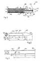
- FIG. 1is a schematic partial cross-sectional view of a radiation applicator in accordance with one embodiment of the Invention
- FIG. 2shows (a) an axial cross-section, and (b) an end elevation of the radiating tip part of the radiation applicator of FIG. 1 ;
- FIG. 3shows a partial transverse cross-section of the metal pipe part of the radiation applicator of FIG. 1 ;
- FIG. 4shows (a) a transverse cross-section, and (b) an axial cross-section, of the tuning washer in the radiation applicator of FIG. 1 ;
- FIG. 5shows (a) an axial cross-section, and (b) an end elevation, of the ferrule in the radiation applicator of FIG. 1 ;
- FIG. 6illustrates (a) an axial cross-section, and (b) a transverse cross-section, of a handle section that may be attached to the metal tube in the radiation applicator of FIG. 1 ;
- FIG. 7illustrates the portion of coaxial cable that passes through the tube, in the radiation applicator of FIG. 1 ;
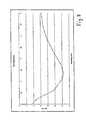
- FIG. 8is a plot of S 11 against frequency for the radiation applicator of FIG. 1 ;
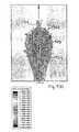
- FIG. 9illustrates (a) the E-field distribution, and (b) the SAR values, around the radiation applicator of FIG. 1 , in use;
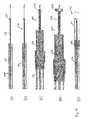
- FIG. 10shows sequentially the assembly of components to form the radiation applicator of FIG. 1 ;
- FIG. 11schematically illustrates a treatment system employing the radiation applicator of FIG. 1 .
- FIG. 1is a schematic partial cross-sectional view of a radiation applicator in accordance with one embodiment of the invention.
- the radiation applicatorgenerally designated 102 , includes a distal end portion of a coaxial cable 104 that is used to couple to a source (not shown) of microwaves, a copper ferrule 106 , a tuning washer 108 attached on the end 110 of the Insulator part of the coaxial cable 104 , and a tip 112 .
- the applicator 102further includes a metal tube 114 : this tube 114 is rigidly attached to the ferrule 106 ; and, as discussed further hereinafter, and annular space 116 is defined between the outer conductor 118 of the cable 104 and the Inner surface of the tube 114 , enabling cooling fluid to enter (in the direction of arrows A), contact the heated parts of the applicator 102 and exit in the direction of arrows B through radial holes 120 in the tube 114 , thereby extracting heat energy from the device.
- a metal tube 114this tube 114 is rigidly attached to the ferrule 106 ; and, as discussed further hereinafter, and annular space 116 is defined between the outer conductor 118 of the cable 104 and the Inner surface of the tube 114 , enabling cooling fluid to enter (in the direction of arrows A), contact the heated parts of the applicator 102 and exit in the direction of arrows B through radial holes 120 in the tube 114 , thereby extracting heat energy
- the washer 108is soldered to a small length 122 of the central conductor 124 of the cable 104 that extends beyond the end 110 of the insulator 126 of the cable 104 .
- the ferrule 106is soldered to a small cylindrical section (indicated as 128 ) of the outer conductor 118 of the cable 104 .
- the tube 114which is preferably stainless steel, but may be made of other suitable materials, such as titanium (or any other medical grade material), is glued to the ferrule 106 by means of adhesive (such as Loctite 638 retaining compound) at the contacting surfaces thereof, indicated at 130 and 132 .
- the tip 112is also glued, using the same adhesive, on the inner surfaces thereof, to corresponding outer surfaces of the ferrule 106 and the cable's insulation 126 .
- the applicator 102When assembled, the applicator 102 forms a unitary device that is rigid and stable along its length, which may be of the order of 25 or so centimeters when the tube 114 is included, making it suitable for insertion into various types of soft tissue.
- the space 116 and holes 120enable cooling fluid to extract heat from the applicator 102 through contact with the ferrule 106 , the outer conductor 118 of the cable 104 and the end of the tube 114 .
- the ferrule 106assists in assuring the applicator's rigidity.
- the exposed end section 134 of cable 104(from which the outer conductor 118 has been removed), in conjunction with the dielectric tip 112 , being fed by a source of radiation of predetermined frequency, operate, in use, as a radiating antenna for radiating microwaves into tissue for therapeutic treatment.
- the applicator 102operates, in use, as a dipole antenna rather than a monopole device, resulting in an emitted radiation pattern that is beneficial, due to its spherical direct heated area (larger burn), for the treatment of certain tissues, such as malignant or tuimorous tissue.
- FIG. 2shows (a) an axial cross-section and (b) an end elevation, of the radiating tip part 112 of the radiation applicator of FIG. 1 (in each case, the dimensions are given in mm).
- the tip 112has inner cylindrical walls 202 , 204 , and abutting walls 206 , 208 , for receiving and abutting the washer 108 and ferrule 106 respectively, during assembly.
- the tip 112is made of zirconia ceramic alloy. More preferably, it is a partially stabilised zirconia (PSZ) having yttria as the stabilising oxidising agent.
- PSZpartially stabilised zirconia
- the tip 112is made of Technox 2000 (available from Dynamic Ceramic), a PSZ having a very fine uniform grain compared to other PSZs, and with a dielectric constant (k) of 25. Appropriate choice of dielectric material assists in determining the properties of the radiated microwave energy (field).
- the transverse dimensionsare relatively small: in the described embodiment the diameter is less than or equal to 2.4 mm; and the tip 112 is designed to have dimensions, and be formed of the specified material, so as to perform effective tissue ablation at the operating microwave frequency, in this case 2.45 GHz.
- the 2.4 mm diameter deviceis thus well adapted for insertion into, and treatment of, cancerous and/or non-cancerous tissue of the liver, brain, lung, veins, bone, etc.
- the end 210 of the tip 112is formed by conventional grinding techniques performed in the manufacture of the tip 112 .
- the end 210may be formed as a fine point (like a needle or pin), or it may be formed with an end blade (e.g. like a chisel), i.e. having a transverse dimension of elongation.
- the latter configurationhas the benefit of being well suited to forcing the tip 112 into or through tissue, i.e. to perforate or puncture the surface (e.g. skin) of tissue.
- the tip 112is preferably coated with a non-stick layer such as silicone or paralene, to facilitate movement relative to tissue.
- FIG. 3shows a partial transverse cross-section of the metal pipe 114 part of the radiation applicator of FIG. 1 .
- the tube 114is suitably made of stainless steel (specifically 13 gauge thin wall 304 welded hard drawn (WHD) stainless steel tube).
- WTDhard drawn
- the tube 114is some 215 mm in length: only the end section that is attached to the ferrule 105 is illustrated in detail in FIG. 3 .
- two sets of holes 120 , 120 ′are provided at 12 and 13 mm, respectively, from the end 302 of the tube 114 .
- These radial holes 120 , 120 ′permit the exit of cooling fluid.
- two sets of holesare shown, 1, 3, 4 or more sets of holes may be provided, in variants of the illustrated embodiment in addition, although two holes per set are shown, 3, 4 5, or more holes per set may be provided, so long as the structural rigidity of the tube 114 is not compromised.
- the holes 120 , 120 ′are of 0.5 mm diameter, but it will be appreciated that this diameter may be quite different, e.g.
- the illustrated distance from the end 302is 12 or 13 mm, in alternative embodiments this may be any thing from 3 mm to 5 cm from the end 302 , in order to control the length of track that requires cauterisation.
- the tube 114may be omitted.
- the treatmentmay comprise delivering the applicator to the treatment location (e.g. tuimorous tissue) by suitable surgical or other techniques.
- the applicatormay then be left in place inside the tumour, the access wound closed, and a sterile connector left at the skull surface for subsequent connection to the microwave source for follow-up treatment at a later date.
- FIG. 4shows (a) a transverse cross-section and (b) an axial cross-section, of the tuning washer 108 in the radiation applicator 102 of FIG. 1 .
- the washer 108is suitably made of copper, although other metals may be used.
- the washer 108has an inner cylindrical surface 402 enabling it to be soldered to the central conductor 124 of the cable 104 (see FIG. 1 ). Although the washer is small, its dimensions are critical.
- the washertunes the applicator, which operates as a dipole radiator (radiating energy from two locations), so that more effective treatment (ablation) of tissue is effected.
- FIG. 5shows (a) an axial cross-section, and (b) an end elevation, of the ferrule 106 in the radiation applicator 102 of FIG. 1 .
- the ferrule 106is suitably made of copper, and is preferably gold plated to protect against any corrosive effects of the cooling fluid, the composition of which is discussed hereinafter.
- the ferrule 106is suitably produced by conventional (e.g. CNC) machining techniques.
- FIG. 6illustrates (a) an axial cross-section and (b) a transverse cross-section at B-B of a handle section 602 that may be attached to the metal tube 114 in the radiation applicator 102 of FIG. 1 .
- the handle section 602is suitably stainless steel, and is preferably formed of the same material as the tube 114 .
- the handle sectionincludes a forward channel 604 enabling insertion of the tube 114 during assembly, and a rear channel 606 enabling insertion of the coax cable 104 during assembly.
- a transverse port BOB having an internal thread 610enables the connection of a (suitably plastic) connector, for connecting to a source of cooling fluid, discussed later. Once assembled, the arrangement enables cooling fluid to pass in the direction of arrow C into the tube 114 (not shown).
- FIG. 7illustrates the portion of coaxial cable 104 that passes through the tube 114 , in the radiation applicator 102 of FIG. 1 .
- the cable 104suitably comprises a low-loss coaxial cable such as SJS-070LL-253-Strip cable.
- a connector 702(suitably SMA female type) permits connection of the cable 104 to a microwave source (not shown), or to an intermediate section of coax cable (not shown) that in turn connect to the microwave source.
- FIG. 8is a plot of S 11 against frequency for the radiation applicator of FIG. 1 . This illustrates the ratio of reflective reflected microwave power from the interface of the applicator 102 and treated tissue to total input power to the applicator 102 . As can be seen, the design of the applicator 102 causes the reflected power to be a minimum, and therefore the transmitted power into the tissue to be a maximum, at the frequency (2.45 GHz) of the delivered microwaves.
- FIG. 9( a )shows the E-field distribution around the radiation applicator 102 of FIG. 1 , in use. Darker colours adjacent the applicator 102 indicate points of higher electric field.
- the position of the washer 108is indicated at 902
- the position of the tip-ferrule junctionis indicated at 904 .
- Two limited substantially cylindrical zones 906 , 908 , of highest electric fieldare thus formed around the applicator 102 at the positions 902 and 904 respectively.
- FIG. 9( b )shows the SAR (specific absorption rate) value distribution around the radiation applicator 102 of FIG. 1 , in use. Darker colours adjacent the applicator 102 indicate points of SAR.
- the position of the washer 108is indicated at 902
- the position of the tip-ferrule junctionis indicated at 904
- the position of the ferrule-tube junctionis indicated at 905 .
- Two limited substantially cylindrical zones 910 , 912 , of highest SARare thus formed around the applicator 102 at the positions 902 and between 904 and 905 , respectively.
- FIG. 10shows sequentially the assembly of components to form the radiation applicator 102 of FIG. 1 .
- the coax cable 104is shown, with the outer conductor 118 and the Inner insulator 126 trimmed back, as illustrated earlier in FIG. 7 .
- the tube 114is then slid over the cable 104 .
- the ferrule 106is slid over the cable 104 (see FIG. 10( c ) , and fixedly attached to the tube 114 and to the cable 104 , as described earlier.
- the washer 108is attached to the inner conductor 124 by soldering, as shown in FIG. 10( d ) .
- the tip 112is slid over the cable 104 and part of the ferrule 106 , and glued thereto, as described earlier; the completed applicator is shown in FIG. 10( e ) . This results in a radiator construction of great rigidity and mechanical stability.
- FIG. 11schematically illustrates a treatment system 1102 employing the radiation applicator 102 of FIG. 1 .
- Microwave source 1104is couple to the input connector 1106 on handle 602 by coaxial cable 1108 .
- the microwave poweris supplied at up to 80 W. However this could be larger for larger size applicators (e.g. up to 200 W for 5 mm dia. applicators)
- Syringe pump 1110operates a syringe 1112 for supplying cooling fluid 1114 via conduit 1116 and connector 1118 attached to handle 602 , to the interior of the handle section 602 .
- the fluidis not at great pressure, but is pumped so as to provide a flow rate of about 1.5 to 2.0 ml/minute through the pipe 114 in the illustrated embodiment.
- the cooling fluidis saline, although other liquids or gases may be used, such as ethanol.
- a cooling liquid having a secondary (cytotoxic) effectcould be used, enhancing the tumour treatment.
- the cooling fluid 1114exits the tube 114 (see arrows B in FIG. 1 ) at a temperature of the order of 10° C. higher than that at which it enters (see arrows A in FIG. 1 ) the tube 114 .
- the cooling fluid 1114may, for example, enter the tube 1114 at room temperature; however, the cooling fluid 1114 may be pre-cooled to below room temperature by any suitable technique.
- the methodology for use of the above-described applicatormay be as conventionally employed in the treatment of various soft tissue tumours.
- the applicatoris inserted into the body, laparoscopically, percutaneously or surgically, moved to the correct position by the user (assisted where necessary by positioning sensors and/or imaging tools, such as ultrasound) so that the tip 112 is embedded in the tissue to be treated.
- the microwave poweris switched on, and the tissue thus ablated for a predetermined period under the control of the user.
- the applicatoris stationary during treatment. However, in some instances (e.g. veins), the applicator may be moved (gentle sliding motion relative to the target tissue) while the microwave radiation is being applied.
Landscapes
- Health & Medical Sciences (AREA)
- Life Sciences & Earth Sciences (AREA)
- Surgery (AREA)
- Biomedical Technology (AREA)
- Engineering & Computer Science (AREA)
- Veterinary Medicine (AREA)
- Animal Behavior & Ethology (AREA)
- Nuclear Medicine, Radiotherapy & Molecular Imaging (AREA)
- Public Health (AREA)
- General Health & Medical Sciences (AREA)
- Heart & Thoracic Surgery (AREA)
- Molecular Biology (AREA)
- Medical Informatics (AREA)
- Otolaryngology (AREA)
- Electromagnetism (AREA)
- Physics & Mathematics (AREA)
- Pathology (AREA)
- Radiology & Medical Imaging (AREA)
- Surgical Instruments (AREA)
- Radiation-Therapy Devices (AREA)
Abstract
Description
Claims (12)
Priority Applications (1)
| Application Number | Priority Date | Filing Date | Title |
|---|---|---|---|
| US14/940,354US9907613B2 (en) | 2005-07-01 | 2015-11-13 | Radiation applicator and method of radiating tissue |
Applications Claiming Priority (3)
| Application Number | Priority Date | Filing Date | Title |
|---|---|---|---|
| GB0414976AGB2415630C2 (en) | 2004-07-02 | 2004-07-02 | Radiation applicator and method of radiating tissue |
| GB0414976.1 | 2004-07-02 | ||
| PCT/EP2005/007103WO2006002943A1 (en) | 2004-07-02 | 2005-07-01 | Radiation applicator and method of radiating tissue |
Related Child Applications (1)
| Application Number | Title | Priority Date | Filing Date |
|---|---|---|---|
| US14/940,354DivisionUS9907613B2 (en) | 2005-07-01 | 2015-11-13 | Radiation applicator and method of radiating tissue |
Publications (2)
| Publication Number | Publication Date |
|---|---|
| US20080275436A1 US20080275436A1 (en) | 2008-11-06 |
| US9788896B2true US9788896B2 (en) | 2017-10-17 |
Family
ID=32843546
Family Applications (1)
| Application Number | Title | Priority Date | Filing Date |
|---|---|---|---|
| US10/577,414Expired - Fee RelatedUS9788896B2 (en) | 2004-07-02 | 2005-07-01 | Radiation applicator and method of radiating tissue |
Country Status (7)
| Country | Link |
|---|---|
| US (1) | US9788896B2 (en) |
| EP (1) | EP1768596B1 (en) |
| JP (1) | JP4908406B2 (en) |
| ES (1) | ES2467092T3 (en) |
| GB (1) | GB2415630C2 (en) |
| TW (1) | TWI375579B (en) |
| WO (1) | WO2006002943A1 (en) |
Cited By (2)
| Publication number | Priority date | Publication date | Assignee | Title |
|---|---|---|---|---|
| US20200171317A1 (en)* | 2018-12-02 | 2020-06-04 | Mohamed A Basiony | System for its use in a tumor treatment |
| USD1084316S1 (en) | 2023-11-20 | 2025-07-15 | Angiodynamics, Inc. | Ferrule |
Families Citing this family (55)
| Publication number | Priority date | Publication date | Assignee | Title |
|---|---|---|---|---|
| GB2403148C2 (en) | 2003-06-23 | 2013-02-13 | Microsulis Ltd | Radiation applicator |
| US20070016181A1 (en) | 2004-04-29 | 2007-01-18 | Van Der Weide Daniel W | Microwave tissue resection tool |
| GB2415630C2 (en) | 2004-07-02 | 2007-03-22 | Microsulis Ltd | Radiation applicator and method of radiating tissue |
| GB2434314B (en)* | 2006-01-03 | 2011-06-15 | Microsulis Ltd | Microwave applicator with dipole antenna |
| US8672932B2 (en) | 2006-03-24 | 2014-03-18 | Neuwave Medical, Inc. | Center fed dipole for use with tissue ablation systems, devices and methods |
| US10363092B2 (en) | 2006-03-24 | 2019-07-30 | Neuwave Medical, Inc. | Transmission line with heat transfer ability |
| US10376314B2 (en) | 2006-07-14 | 2019-08-13 | Neuwave Medical, Inc. | Energy delivery systems and uses thereof |
| US11389235B2 (en) | 2006-07-14 | 2022-07-19 | Neuwave Medical, Inc. | Energy delivery systems and uses thereof |
| CN101511295B (en) | 2006-07-14 | 2012-09-05 | 纽华沃医药公司 | Energy transfer systems and their uses |
| GB0620063D0 (en)* | 2006-10-10 | 2006-11-22 | Medical Device Innovations Ltd | Needle structure and method of performing needle biopsies |
| US20090005766A1 (en)* | 2007-06-28 | 2009-01-01 | Joseph Brannan | Broadband microwave applicator |
| US8945111B2 (en)* | 2008-01-23 | 2015-02-03 | Covidien Lp | Choked dielectric loaded tip dipole microwave antenna |
| GB2457299B (en) | 2008-02-09 | 2013-04-24 | Uk Investments Associates Llc | Microwave applicator |
| US8059059B2 (en) | 2008-05-29 | 2011-11-15 | Vivant Medical, Inc. | Slidable choke microwave antenna |
| US8251987B2 (en) | 2008-08-28 | 2012-08-28 | Vivant Medical, Inc. | Microwave antenna |
| US9113924B2 (en) | 2008-10-17 | 2015-08-25 | Covidien Lp | Choked dielectric loaded tip dipole microwave antenna |
| US8118808B2 (en) | 2009-03-10 | 2012-02-21 | Vivant Medical, Inc. | Cooled dielectrically buffered microwave dipole antenna |
| JP5629434B2 (en)* | 2009-05-01 | 2014-11-19 | 国立大学法人滋賀医科大学 | Microwave surgical device |
| US10022202B2 (en) | 2013-03-15 | 2018-07-17 | Triagenics, Llc | Therapeutic tooth bud ablation |
| CA2761652C (en) | 2009-05-11 | 2019-10-01 | Leigh E. Colby | Therapeutic tooth bud ablation |
| WO2014143014A1 (en) | 2013-03-15 | 2014-09-18 | Triagenics, Llc | Therapeutic tooth bud ablation |
| US8235981B2 (en) | 2009-06-02 | 2012-08-07 | Vivant Medical, Inc. | Electrosurgical devices with directional radiation pattern |
| EP3549544B1 (en) | 2009-07-28 | 2021-01-06 | Neuwave Medical, Inc. | DEVICE FOR ABLATION |
| GB2474233A (en) | 2009-10-06 | 2011-04-13 | Uk Investments Associates Llc | Cooling pump comprising a detachable head portion |
| US8551083B2 (en) | 2009-11-17 | 2013-10-08 | Bsd Medical Corporation | Microwave coagulation applicator and system |
| US9993294B2 (en)* | 2009-11-17 | 2018-06-12 | Perseon Corporation | Microwave coagulation applicator and system with fluid injection |
| US20110125148A1 (en)* | 2009-11-17 | 2011-05-26 | Turner Paul F | Multiple Frequency Energy Supply and Coagulation System |
| US8882759B2 (en) | 2009-12-18 | 2014-11-11 | Covidien Lp | Microwave ablation system with dielectric temperature probe |
| US8568404B2 (en) | 2010-02-19 | 2013-10-29 | Covidien Lp | Bipolar electrode probe for ablation monitoring |
| ES2856026T3 (en) | 2010-05-03 | 2021-09-27 | Neuwave Medical Inc | Power supply systems |
| US9492190B2 (en)* | 2011-02-09 | 2016-11-15 | Covidien Lp | Tissue dissectors |
| US9198724B2 (en) | 2011-04-08 | 2015-12-01 | Covidien Lp | Microwave tissue dissection and coagulation |
| US9192438B2 (en) | 2011-12-21 | 2015-11-24 | Neuwave Medical, Inc. | Energy delivery systems and uses thereof |
| US9901398B2 (en)* | 2012-06-29 | 2018-02-27 | Covidien Lp | Microwave antenna probes |
| US9888956B2 (en) | 2013-01-22 | 2018-02-13 | Angiodynamics, Inc. | Integrated pump and generator device and method of use |
| CN104323856B (en) | 2014-11-11 | 2017-07-18 | 南京维京九洲医疗器械研发中心 | Without magnetic water-cooled microwave ablation needle manufacture method |
| US10660691B2 (en) | 2015-10-07 | 2020-05-26 | Angiodynamics, Inc. | Multiple use subassembly with integrated fluid delivery system for use with single or dual-lumen peristaltic tubing |
| CN113367788B (en) | 2015-10-26 | 2024-09-06 | 纽韦弗医疗设备公司 | Energy delivery systems and uses thereof |
| BR112018008233B1 (en) | 2015-10-26 | 2022-10-04 | Neuwave Medical, Inc | APPARATUS FOR FASTENING A MEDICAL DEVICE, METHOD FOR FASTENING A MEDICAL DEVICE IN A DESIRED POSITION, AND KIT |
| CN105561477B (en)* | 2015-12-18 | 2017-11-14 | 郑州大学第一附属医院 | A kind of changeable type microwave probe |
| US10531917B2 (en) | 2016-04-15 | 2020-01-14 | Neuwave Medical, Inc. | Systems and methods for energy delivery |
| WO2018140816A1 (en) | 2017-01-26 | 2018-08-02 | Broncus Medical Inc. | Bronchoscopic-based microwave ablation system and method |
| US20190246876A1 (en) | 2018-02-15 | 2019-08-15 | Neuwave Medical, Inc. | Compositions and methods for directing endoscopic devices |
| US20190247117A1 (en) | 2018-02-15 | 2019-08-15 | Neuwave Medical, Inc. | Energy delivery devices and related systems and methods thereof |
| US11672596B2 (en) | 2018-02-26 | 2023-06-13 | Neuwave Medical, Inc. | Energy delivery devices with flexible and adjustable tips |
| GB2577706A (en) | 2018-10-03 | 2020-04-08 | Creo Medical Ltd | Electrosurgical instrument |
| CN109199582B (en)* | 2018-10-30 | 2020-11-20 | 赛诺微医疗科技(浙江)有限公司 | Wide-range microwave ablation antenna and lung microwave ablation soft electrode adopting same |
| WO2020087274A1 (en)* | 2018-10-30 | 2020-05-07 | 赛诺微医疗科技(浙江)有限公司 | Wide-range microwave ablation antenna and lung microwave ablation soft electrode using same |
| US20200168360A1 (en) | 2018-11-27 | 2020-05-28 | Neuwave Medical, Inc. | Systems and methods for energy delivery |
| US11832880B2 (en) | 2018-12-13 | 2023-12-05 | Neuwave Medical, Inc. | Energy delivery devices and related systems and methods thereof |
| US11832879B2 (en) | 2019-03-08 | 2023-12-05 | Neuwave Medical, Inc. | Systems and methods for energy delivery |
| EP4413935A3 (en)* | 2019-06-06 | 2024-09-18 | TriAgenics, Inc. | Ablation probe systems |
| US20230088132A1 (en) | 2021-09-22 | 2023-03-23 | NewWave Medical, Inc. | Systems and methods for real-time image-based device localization |
| US20250152264A1 (en) | 2022-02-18 | 2025-05-15 | Neuwave Medical, Inc. | Coupling devices and related systems |
| US20240285332A1 (en) | 2023-02-24 | 2024-08-29 | Neuwave Medical, Inc. | Temperature regulating devices and related systems and methods |
Citations (95)
| Publication number | Priority date | Publication date | Assignee | Title |
|---|---|---|---|---|
| US3065752A (en) | 1959-11-14 | 1962-11-27 | Philips Corp | High frequency therapeutic radiator |
| US3461261A (en) | 1966-10-31 | 1969-08-12 | Du Pont | Heating apparatus |
| US3871359A (en) | 1973-06-25 | 1975-03-18 | Interscience Technology Corp | Impedance measuring system |
| GB2074826A (en) | 1980-01-22 | 1981-11-04 | Por Microtrans Ab | Microwave heating applicator |
| EP0105677A1 (en) | 1982-09-27 | 1984-04-18 | Kureha Kagaku Kogyo Kabushiki Kaisha | Endotract antenna device for hyperthermia |
| US4446874A (en) | 1981-12-30 | 1984-05-08 | Clini-Therm Corporation | Microwave applicator with discoupled input coupling and frequency tuning functions |
| US4476363A (en) | 1980-01-03 | 1984-10-09 | Stiftelsen Institutet For Mikrovagsteknik Vid Tekniska Hogskolan I Stockholm | Method and device for heating by microwave energy |
| US4557272A (en) | 1980-03-31 | 1985-12-10 | Microwave Associates, Inc. | Microwave endoscope detection and treatment system |
| US4612940A (en)* | 1984-05-09 | 1986-09-23 | Scd Incorporated | Microwave dipole probe for in vivo localized hyperthermia |
| US4676258A (en) | 1983-01-24 | 1987-06-30 | Kureha Kagaku Kogyo Kabushiki Kaisha | Device for hyperthermia |
| EP0294854A2 (en) | 1983-01-12 | 1988-12-14 | The University of Glasgow, University Court | Microwave thermographic apparatus |
| US4891483A (en) | 1985-06-29 | 1990-01-02 | Tokyo Keiki Co. Ltd. | Heating apparatus for hyperthermia |
| US5227730A (en) | 1992-09-14 | 1993-07-13 | Kdc Technology Corp. | Microwave needle dielectric sensors |
| US5364392A (en) | 1993-05-14 | 1994-11-15 | Fidus Medical Technology Corporation | Microwave ablation catheter system with impedance matching tuner and method |
| US5370644A (en) | 1988-11-25 | 1994-12-06 | Sensor Electronics, Inc. | Radiofrequency ablation catheter |
| US5458597A (en) | 1993-11-08 | 1995-10-17 | Zomed International | Device for treating cancer and non-malignant tumors and methods |
| US5536267A (en) | 1993-11-08 | 1996-07-16 | Zomed International | Multiple electrode ablation apparatus |
| US5540737A (en) | 1991-06-26 | 1996-07-30 | Massachusetts Institute Of Technology | Minimally invasive monopole phased array hyperthermia applicators and method for treating breast carcinomas |
| US5620479A (en) | 1992-11-13 | 1997-04-15 | The Regents Of The University Of California | Method and apparatus for thermal therapy of tumors |
| US5628770A (en)* | 1995-06-06 | 1997-05-13 | Urologix, Inc. | Devices for transurethral thermal therapy |
| US5630426A (en) | 1995-03-03 | 1997-05-20 | Neovision Corporation | Apparatus and method for characterization and treatment of tumors |
| US5683384A (en) | 1993-11-08 | 1997-11-04 | Zomed | Multiple antenna ablation apparatus |
| US5728143A (en) | 1995-08-15 | 1998-03-17 | Rita Medical Systems, Inc. | Multiple antenna ablation apparatus and method |
| US5735847A (en) | 1995-08-15 | 1998-04-07 | Zomed International, Inc. | Multiple antenna ablation apparatus and method with cooling element |
| US5800484A (en) | 1995-08-15 | 1998-09-01 | Rita Medical Systems, Inc. | Multiple antenna ablation apparatus with expanded electrodes |
| US5800494A (en)* | 1996-08-20 | 1998-09-01 | Fidus Medical Technology Corporation | Microwave ablation catheters having antennas with distal fire capabilities |
| US5807272A (en) | 1995-10-31 | 1998-09-15 | Worcester Polytechnic Institute | Impedance spectroscopy system for ischemia monitoring and detection |
| US5810742A (en) | 1994-10-24 | 1998-09-22 | Transcan Research & Development Co., Ltd. | Tissue characterization based on impedance images and on impedance measurements |
| WO1999007297A1 (en) | 1997-08-05 | 1999-02-18 | Trustees Of Dartmouth College | System and methods for fallopian tube occlusion |
| US5873849A (en) | 1997-04-24 | 1999-02-23 | Ichor Medical Systems, Inc. | Electrodes and electrode arrays for generating electroporation inducing electrical fields |
| US5904709A (en)* | 1996-04-17 | 1999-05-18 | The United States Of America As Represented By The Administrator Of The National Aeronautics And Space Administration | Microwave treatment for cardiac arrhythmias |
| CA2339277A1 (en) | 1998-05-06 | 1999-11-11 | Microsulis Plc | Microwave applicator |
| US6009347A (en) | 1998-01-27 | 1999-12-28 | Genetronics, Inc. | Electroporation apparatus with connective electrode template |
| US6016452A (en) | 1996-03-19 | 2000-01-18 | Kasevich; Raymond S. | Dynamic heating method and radio frequency thermal treatment |
| US6027502A (en) | 1998-01-29 | 2000-02-22 | Desai; Ashvin H. | Surgical apparatus providing tool access and replaceable irrigation pump cartridge |
| WO2000009208A1 (en) | 1998-08-14 | 2000-02-24 | K.U. Leuven Research & Development | Cooled-wet electrode |
| US6047216A (en)* | 1996-04-17 | 2000-04-04 | The United States Of America Represented By The Administrator Of The National Aeronautics And Space Administration | Endothelium preserving microwave treatment for atherosclerosis |
| US6050994A (en) | 1998-05-05 | 2000-04-18 | Cardiac Pacemakers, Inc. | RF ablation apparatus and method using controllable duty cycle with alternate phasing |
| US6066134A (en) | 1992-01-07 | 2000-05-23 | Arthrocare Corporation | Method for electrosurgical cutting and ablation |
| US6106524A (en) | 1995-03-03 | 2000-08-22 | Neothermia Corporation | Methods and apparatus for therapeutic cauterization of predetermined volumes of biological tissue |
| US6134460A (en) | 1988-11-02 | 2000-10-17 | Non-Invasive Technology, Inc. | Spectrophotometers with catheters for measuring internal tissue |
| US6200314B1 (en) | 1998-05-05 | 2001-03-13 | Cardiac Pacemakers, Inc. | RF ablation apparatus and method using unipolar and bipolar techniques |
| US6223085B1 (en)* | 1997-05-06 | 2001-04-24 | Urologix, Inc. | Device and method for preventing restenosis |
| US20010008966A1 (en) | 1996-04-17 | 2001-07-19 | Government Of The United States Of America As Represented By The Administrator, Nasa | Computer program for microwave antenna |
| US6287302B1 (en) | 1999-06-14 | 2001-09-11 | Fidus Medical Technology Corporation | End-firing microwave ablation instrument with horn reflection device |
| US6296636B1 (en) | 1994-05-10 | 2001-10-02 | Arthrocare Corporation | Power supply and methods for limiting power in electrosurgery |
| US6298726B1 (en) | 1998-06-25 | 2001-10-09 | Olympus Optical Co., Ltd. | Acoustic impedance measuring apparatus using ultrasonic waves |
| JP2002109971A (en) | 2000-09-27 | 2002-04-12 | Mitsubishi Cable Ind Ltd | Highly foamed plastic insulation coaxial cable |
| US20020077627A1 (en) | 2000-07-25 | 2002-06-20 | Johnson Theodore C. | Method for detecting and treating tumors using localized impedance measurement |
| US6436072B1 (en) | 1996-08-15 | 2002-08-20 | Deka Products Limited Partnership | Medical irrigation pump and system |
| US20020161361A1 (en) | 1998-05-05 | 2002-10-31 | Sherman Marshall L. | RF ablation system and method having automatic temperature control |
| US6478793B1 (en) | 1999-06-11 | 2002-11-12 | Sherwood Services Ag | Ablation treatment of bone metastases |
| US6485487B1 (en) | 1998-05-05 | 2002-11-26 | Cardiac Pacemakers, Inc. | RF ablation apparatus having high output impedance drivers |
| US6496738B2 (en)* | 1995-09-06 | 2002-12-17 | Kenneth L. Carr | Dual frequency microwave heating apparatus |
| US6497704B2 (en) | 2001-04-04 | 2002-12-24 | Moshe Ein-Gal | Electrosurgical apparatus |
| US20030088242A1 (en) | 2001-11-02 | 2003-05-08 | Mani Prakash | High-strength microwave antenna assemblies |
| US20030100894A1 (en) | 2001-11-23 | 2003-05-29 | John Mahon | Invasive therapeutic probe |
| US20030109862A1 (en) | 2001-11-02 | 2003-06-12 | Mani Prakash | High-strength microwave antenna assemblies and methods of use |
| US6616657B2 (en) | 1998-05-05 | 2003-09-09 | Cardiac Pacemakers, Inc. | RF ablation catheter tip electrode with multiple thermal sensors |
| GB2387544A (en) | 2002-10-10 | 2003-10-22 | Microsulis Plc | Microwave Applicator |
| US6673070B2 (en) | 1994-06-24 | 2004-01-06 | Curon Medical, Inc. | Sphincter treatment apparatus |
| US20040049254A1 (en) | 2001-01-31 | 2004-03-11 | Iginio Longo | Interstitial microwave antenna with miniaturized choke hyperthermia in medicine and surgery |
| US6712811B2 (en) | 1998-02-20 | 2004-03-30 | Arthrocare Corporation | Methods for electrosurgical spine surgery |
| US6723094B1 (en) | 1998-12-18 | 2004-04-20 | Kai Desinger | Electrode assembly for a surgical instrument provided for carrying out an electrothermal coagulation of tissue |
| US6770070B1 (en) | 2000-03-17 | 2004-08-03 | Rita Medical Systems, Inc. | Lung treatment apparatus and method |
| US20040204679A1 (en) | 1998-01-29 | 2004-10-14 | Allegiance Healthcare Corporation | Disposable surgical suction/irrigation trumpet valve tube cassette |
| US20040215185A1 (en) | 2001-10-18 | 2004-10-28 | Csaba Truckai | Electrosurgical working end for cotrolled energy delivery |
| US20040267340A1 (en) | 2002-12-12 | 2004-12-30 | Wit Ip Corporation | Modular thermal treatment systems with single-use disposable catheter assemblies and related methods |
| US20050015081A1 (en) | 2003-07-18 | 2005-01-20 | Roman Turovskiy | Devices and methods for cooling microwave antennas |
| US20050033276A1 (en) | 2003-07-07 | 2005-02-10 | Olympus Corporation | Blood vessel detection device |
| US6869430B2 (en) | 2000-03-31 | 2005-03-22 | Rita Medical Systems, Inc. | Tissue biopsy and treatment apparatus and method |
| GB2406521A (en) | 2003-10-03 | 2005-04-06 | Microsulis Ltd | Microwave applicator for treating varicose veins |
| US20050107781A1 (en) | 2003-11-18 | 2005-05-19 | Isaac Ostrovsky | System and method for tissue ablation |
| US20050245920A1 (en)* | 2004-04-30 | 2005-11-03 | Vitullo Jeffrey M | Cell necrosis apparatus with cooled microwave antenna |
| GB2415630A (en) | 2004-07-02 | 2006-01-04 | Microsulis Ltd | Microwave applicator with pumped cooling and dielectric tip. |
| US7008421B2 (en) | 2002-08-21 | 2006-03-07 | Resect Medical, Inc. | Apparatus and method for tissue resection |
| US20060217704A1 (en) | 2005-02-04 | 2006-09-28 | Instrumedical Ltd. | Electro-surgical needle apparatus |
| US20060293734A1 (en) | 2005-04-27 | 2006-12-28 | Scott David J | Apparatus and method for providing enhanced heat transfer from a body |
| US20070191825A1 (en) | 2003-10-03 | 2007-08-16 | Nigel Cronin | Device and method for the treatment of hollow anatomical structures |
| US20070203551A1 (en) | 2005-07-01 | 2007-08-30 | Microsulis Limited | Radiation applicator and method of radiating tissue |
| US7553309B2 (en) | 2004-10-08 | 2009-06-30 | Covidien Ag | Electrosurgical system employing multiple electrodes and method thereof |
| US20090240247A1 (en) | 2003-11-14 | 2009-09-24 | Boston Scientific Scimed, Inc. | Systems and methods for performing simultaneous ablation |
| US7776035B2 (en) | 2004-10-08 | 2010-08-17 | Covidien Ag | Cool-tip combined electrode introducer |
| US7846108B2 (en) | 2002-04-16 | 2010-12-07 | Vivant Medical, Inc. | Localization element with energized tip |
| US20110230874A1 (en) | 2005-07-01 | 2011-09-22 | Halt Medical Inc. | Ablation method |
| US8073550B1 (en) | 1997-07-31 | 2011-12-06 | Miramar Labs, Inc. | Method and apparatus for treating subcutaneous histological features |
| US8182477B2 (en) | 2004-10-08 | 2012-05-22 | Covidien Ag | Electrosurgical system employing multiple electrodes and method thereof |
| US8579902B2 (en) | 2004-10-15 | 2013-11-12 | Baxano Signal, Inc. | Devices and methods for tissue modification |
| US8613745B2 (en) | 2004-10-15 | 2013-12-24 | Baxano Surgical, Inc. | Methods, systems and devices for carpal tunnel release |
| US8647346B2 (en) | 2004-10-15 | 2014-02-11 | Baxano Surgical, Inc. | Devices and methods for tissue modification |
| US8652138B2 (en) | 2004-10-15 | 2014-02-18 | Baxano Surgical, Inc. | Flexible tissue rasp |
| US8801626B2 (en) | 2004-10-15 | 2014-08-12 | Baxano Surgical, Inc. | Flexible neural localization devices and methods |
| US9101386B2 (en) | 2004-10-15 | 2015-08-11 | Amendia, Inc. | Devices and methods for treating tissue |
| US20160000505A1 (en) | 2003-06-23 | 2016-01-07 | Angiodynamics, Inc. | Radiation Applicator for Microwave Medical Treatment |
| US9247952B2 (en) | 2004-10-15 | 2016-02-02 | Amendia, Inc. | Devices and methods for tissue access |
Family Cites Families (1)
| Publication number | Priority date | Publication date | Assignee | Title |
|---|---|---|---|---|
| JP4138469B2 (en)* | 2002-12-06 | 2008-08-27 | アルフレッサファーマ株式会社 | Microwave surgical device |
- 2004
- 2004-07-02GBGB0414976Apatent/GB2415630C2/ennot_activeExpired - Fee Related
- 2005
- 2005-06-22TWTW094120771Apatent/TWI375579B/ennot_activeIP Right Cessation
- 2005-07-01ESES05761213.7Tpatent/ES2467092T3/ennot_activeExpired - Lifetime
- 2005-07-01USUS10/577,414patent/US9788896B2/ennot_activeExpired - Fee Related
- 2005-07-01JPJP2007518548Apatent/JP4908406B2/ennot_activeExpired - Fee Related
- 2005-07-01EPEP05761213.7Apatent/EP1768596B1/ennot_activeExpired - Lifetime
- 2005-07-01WOPCT/EP2005/007103patent/WO2006002943A1/enactiveApplication Filing
Patent Citations (127)
| Publication number | Priority date | Publication date | Assignee | Title |
|---|---|---|---|---|
| US3065752A (en) | 1959-11-14 | 1962-11-27 | Philips Corp | High frequency therapeutic radiator |
| US3461261A (en) | 1966-10-31 | 1969-08-12 | Du Pont | Heating apparatus |
| US3871359A (en) | 1973-06-25 | 1975-03-18 | Interscience Technology Corp | Impedance measuring system |
| US4476363A (en) | 1980-01-03 | 1984-10-09 | Stiftelsen Institutet For Mikrovagsteknik Vid Tekniska Hogskolan I Stockholm | Method and device for heating by microwave energy |
| GB2074826A (en) | 1980-01-22 | 1981-11-04 | Por Microtrans Ab | Microwave heating applicator |
| US4557272A (en) | 1980-03-31 | 1985-12-10 | Microwave Associates, Inc. | Microwave endoscope detection and treatment system |
| US4446874A (en) | 1981-12-30 | 1984-05-08 | Clini-Therm Corporation | Microwave applicator with discoupled input coupling and frequency tuning functions |
| EP0105677A1 (en) | 1982-09-27 | 1984-04-18 | Kureha Kagaku Kogyo Kabushiki Kaisha | Endotract antenna device for hyperthermia |
| EP0294854A2 (en) | 1983-01-12 | 1988-12-14 | The University of Glasgow, University Court | Microwave thermographic apparatus |
| US4676258A (en) | 1983-01-24 | 1987-06-30 | Kureha Kagaku Kogyo Kabushiki Kaisha | Device for hyperthermia |
| US4612940A (en)* | 1984-05-09 | 1986-09-23 | Scd Incorporated | Microwave dipole probe for in vivo localized hyperthermia |
| US4891483A (en) | 1985-06-29 | 1990-01-02 | Tokyo Keiki Co. Ltd. | Heating apparatus for hyperthermia |
| US6134460A (en) | 1988-11-02 | 2000-10-17 | Non-Invasive Technology, Inc. | Spectrophotometers with catheters for measuring internal tissue |
| US5370644A (en) | 1988-11-25 | 1994-12-06 | Sensor Electronics, Inc. | Radiofrequency ablation catheter |
| US5540737A (en) | 1991-06-26 | 1996-07-30 | Massachusetts Institute Of Technology | Minimally invasive monopole phased array hyperthermia applicators and method for treating breast carcinomas |
| US6066134A (en) | 1992-01-07 | 2000-05-23 | Arthrocare Corporation | Method for electrosurgical cutting and ablation |
| US5227730A (en) | 1992-09-14 | 1993-07-13 | Kdc Technology Corp. | Microwave needle dielectric sensors |
| US5620479A (en) | 1992-11-13 | 1997-04-15 | The Regents Of The University Of California | Method and apparatus for thermal therapy of tumors |
| US5364392A (en) | 1993-05-14 | 1994-11-15 | Fidus Medical Technology Corporation | Microwave ablation catheter system with impedance matching tuner and method |
| US5683384A (en) | 1993-11-08 | 1997-11-04 | Zomed | Multiple antenna ablation apparatus |
| US5536267A (en) | 1993-11-08 | 1996-07-16 | Zomed International | Multiple electrode ablation apparatus |
| US5458597A (en) | 1993-11-08 | 1995-10-17 | Zomed International | Device for treating cancer and non-malignant tumors and methods |
| US6296636B1 (en) | 1994-05-10 | 2001-10-02 | Arthrocare Corporation | Power supply and methods for limiting power in electrosurgery |
| US6673070B2 (en) | 1994-06-24 | 2004-01-06 | Curon Medical, Inc. | Sphincter treatment apparatus |
| US5810742A (en) | 1994-10-24 | 1998-09-22 | Transcan Research & Development Co., Ltd. | Tissue characterization based on impedance images and on impedance measurements |
| US5630426A (en) | 1995-03-03 | 1997-05-20 | Neovision Corporation | Apparatus and method for characterization and treatment of tumors |
| US6106524A (en) | 1995-03-03 | 2000-08-22 | Neothermia Corporation | Methods and apparatus for therapeutic cauterization of predetermined volumes of biological tissue |
| US5628770A (en)* | 1995-06-06 | 1997-05-13 | Urologix, Inc. | Devices for transurethral thermal therapy |
| US5800484A (en) | 1995-08-15 | 1998-09-01 | Rita Medical Systems, Inc. | Multiple antenna ablation apparatus with expanded electrodes |
| US5728143A (en) | 1995-08-15 | 1998-03-17 | Rita Medical Systems, Inc. | Multiple antenna ablation apparatus and method |
| US5735847A (en) | 1995-08-15 | 1998-04-07 | Zomed International, Inc. | Multiple antenna ablation apparatus and method with cooling element |
| US6496738B2 (en)* | 1995-09-06 | 2002-12-17 | Kenneth L. Carr | Dual frequency microwave heating apparatus |
| US5807272A (en) | 1995-10-31 | 1998-09-15 | Worcester Polytechnic Institute | Impedance spectroscopy system for ischemia monitoring and detection |
| US6016452A (en) | 1996-03-19 | 2000-01-18 | Kasevich; Raymond S. | Dynamic heating method and radio frequency thermal treatment |
| US5904709A (en)* | 1996-04-17 | 1999-05-18 | The United States Of America As Represented By The Administrator Of The National Aeronautics And Space Administration | Microwave treatment for cardiac arrhythmias |
| US20010008966A1 (en) | 1996-04-17 | 2001-07-19 | Government Of The United States Of America As Represented By The Administrator, Nasa | Computer program for microwave antenna |
| US6047216A (en)* | 1996-04-17 | 2000-04-04 | The United States Of America Represented By The Administrator Of The National Aeronautics And Space Administration | Endothelium preserving microwave treatment for atherosclerosis |
| US6223086B1 (en) | 1996-04-17 | 2001-04-24 | The United States Of America As Represented By The Administrator Of The National Aeronautics And Space Administration | Endothelium preserving microwave treatment for atherosclerosis |
| US6134476A (en) | 1996-04-17 | 2000-10-17 | The United States Of America As Represented By The Administrator Of The National Aeronautics And Space Administration | Transcatheter antenna for microwave treatment |
| US6436072B1 (en) | 1996-08-15 | 2002-08-20 | Deka Products Limited Partnership | Medical irrigation pump and system |
| US5800494A (en)* | 1996-08-20 | 1998-09-01 | Fidus Medical Technology Corporation | Microwave ablation catheters having antennas with distal fire capabilities |
| US5873849A (en) | 1997-04-24 | 1999-02-23 | Ichor Medical Systems, Inc. | Electrodes and electrode arrays for generating electroporation inducing electrical fields |
| US6223085B1 (en)* | 1997-05-06 | 2001-04-24 | Urologix, Inc. | Device and method for preventing restenosis |
| US8073550B1 (en) | 1997-07-31 | 2011-12-06 | Miramar Labs, Inc. | Method and apparatus for treating subcutaneous histological features |
| US8853600B2 (en) | 1997-07-31 | 2014-10-07 | Miramar Labs, Inc. | Method and apparatus for treating subcutaneous histological features |
| WO1999007297A1 (en) | 1997-08-05 | 1999-02-18 | Trustees Of Dartmouth College | System and methods for fallopian tube occlusion |
| US6009347A (en) | 1998-01-27 | 1999-12-28 | Genetronics, Inc. | Electroporation apparatus with connective electrode template |
| US20040204679A1 (en) | 1998-01-29 | 2004-10-14 | Allegiance Healthcare Corporation | Disposable surgical suction/irrigation trumpet valve tube cassette |
| US6027502A (en) | 1998-01-29 | 2000-02-22 | Desai; Ashvin H. | Surgical apparatus providing tool access and replaceable irrigation pump cartridge |
| US6712811B2 (en) | 1998-02-20 | 2004-03-30 | Arthrocare Corporation | Methods for electrosurgical spine surgery |
| US6050994A (en) | 1998-05-05 | 2000-04-18 | Cardiac Pacemakers, Inc. | RF ablation apparatus and method using controllable duty cycle with alternate phasing |
| US6558378B2 (en) | 1998-05-05 | 2003-05-06 | Cardiac Pacemakers, Inc. | RF ablation system and method having automatic temperature control |
| US20020161361A1 (en) | 1998-05-05 | 2002-10-31 | Sherman Marshall L. | RF ablation system and method having automatic temperature control |
| US6200314B1 (en) | 1998-05-05 | 2001-03-13 | Cardiac Pacemakers, Inc. | RF ablation apparatus and method using unipolar and bipolar techniques |
| US6485487B1 (en) | 1998-05-05 | 2002-11-26 | Cardiac Pacemakers, Inc. | RF ablation apparatus having high output impedance drivers |
| US6488678B2 (en) | 1998-05-05 | 2002-12-03 | Cardiac Pacemakers, Inc. | RF ablation apparatus and method using unipolar and bipolar techniques |
| US6616657B2 (en) | 1998-05-05 | 2003-09-09 | Cardiac Pacemakers, Inc. | RF ablation catheter tip electrode with multiple thermal sensors |
| CA2339277A1 (en) | 1998-05-06 | 1999-11-11 | Microsulis Plc | Microwave applicator |
| US6635055B1 (en) | 1998-05-06 | 2003-10-21 | Microsulis Plc | Microwave applicator for endometrial ablation |
| US6298726B1 (en) | 1998-06-25 | 2001-10-09 | Olympus Optical Co., Ltd. | Acoustic impedance measuring apparatus using ultrasonic waves |
| US6514251B1 (en)* | 1998-08-14 | 2003-02-04 | K.U. Leuven Research & Development | Cooled-wet electrode |
| WO2000009208A1 (en) | 1998-08-14 | 2000-02-24 | K.U. Leuven Research & Development | Cooled-wet electrode |
| US6723094B1 (en) | 1998-12-18 | 2004-04-20 | Kai Desinger | Electrode assembly for a surgical instrument provided for carrying out an electrothermal coagulation of tissue |
| US6478793B1 (en) | 1999-06-11 | 2002-11-12 | Sherwood Services Ag | Ablation treatment of bone metastases |
| US6287302B1 (en) | 1999-06-14 | 2001-09-11 | Fidus Medical Technology Corporation | End-firing microwave ablation instrument with horn reflection device |
| US6770070B1 (en) | 2000-03-17 | 2004-08-03 | Rita Medical Systems, Inc. | Lung treatment apparatus and method |
| US6869430B2 (en) | 2000-03-31 | 2005-03-22 | Rita Medical Systems, Inc. | Tissue biopsy and treatment apparatus and method |
| US20140081255A1 (en) | 2000-07-25 | 2014-03-20 | Angiodynamics, Inc. | Method and Apparatuses for Tissue Treatment |
| US6962587B2 (en) | 2000-07-25 | 2005-11-08 | Rita Medical Systems, Inc. | Method for detecting and treating tumors using localized impedance measurement |
| US20020077627A1 (en) | 2000-07-25 | 2002-06-20 | Johnson Theodore C. | Method for detecting and treating tumors using localized impedance measurement |
| JP2002109971A (en) | 2000-09-27 | 2002-04-12 | Mitsubishi Cable Ind Ltd | Highly foamed plastic insulation coaxial cable |
| US20040049254A1 (en) | 2001-01-31 | 2004-03-11 | Iginio Longo | Interstitial microwave antenna with miniaturized choke hyperthermia in medicine and surgery |
| US6497704B2 (en) | 2001-04-04 | 2002-12-24 | Moshe Ein-Gal | Electrosurgical apparatus |
| US20040215185A1 (en) | 2001-10-18 | 2004-10-28 | Csaba Truckai | Electrosurgical working end for cotrolled energy delivery |
| US20030109862A1 (en) | 2001-11-02 | 2003-06-12 | Mani Prakash | High-strength microwave antenna assemblies and methods of use |
| US20030088242A1 (en) | 2001-11-02 | 2003-05-08 | Mani Prakash | High-strength microwave antenna assemblies |
| US20030100894A1 (en) | 2001-11-23 | 2003-05-29 | John Mahon | Invasive therapeutic probe |
| US6706040B2 (en)* | 2001-11-23 | 2004-03-16 | Medlennium Technologies, Inc. | Invasive therapeutic probe |
| US7846108B2 (en) | 2002-04-16 | 2010-12-07 | Vivant Medical, Inc. | Localization element with energized tip |
| US7008421B2 (en) | 2002-08-21 | 2006-03-07 | Resect Medical, Inc. | Apparatus and method for tissue resection |
| GB2387544A (en) | 2002-10-10 | 2003-10-22 | Microsulis Plc | Microwave Applicator |
| US20060151485A1 (en) | 2002-10-10 | 2006-07-13 | Nigel Cronin | Microwave applicator |
| US8586897B2 (en) | 2002-10-10 | 2013-11-19 | Angio Dynamics, Inc. | Microwave applicator |
| US20140042154A1 (en) | 2002-10-10 | 2014-02-13 | Angiodynamics, Inc. | Microwave Application |
| US20080314894A1 (en) | 2002-10-10 | 2008-12-25 | Nigel Cronin | Microwave application |
| WO2004033039A1 (en) | 2002-10-10 | 2004-04-22 | Microsulis Limited | Microwave applicator |
| AU2003267607A1 (en) | 2002-10-10 | 2004-05-04 | Uk Investment Associates Llc | Microwave applicator |
| US20040267340A1 (en) | 2002-12-12 | 2004-12-30 | Wit Ip Corporation | Modular thermal treatment systems with single-use disposable catheter assemblies and related methods |
| US20160000505A1 (en) | 2003-06-23 | 2016-01-07 | Angiodynamics, Inc. | Radiation Applicator for Microwave Medical Treatment |
| US20050033276A1 (en) | 2003-07-07 | 2005-02-10 | Olympus Corporation | Blood vessel detection device |
| US7488292B2 (en) | 2003-07-07 | 2009-02-10 | Olympus Corporation | Blood vessel detection device |
| US7311703B2 (en)* | 2003-07-18 | 2007-12-25 | Vivant Medical, Inc. | Devices and methods for cooling microwave antennas |
| US20050015081A1 (en) | 2003-07-18 | 2005-01-20 | Roman Turovskiy | Devices and methods for cooling microwave antennas |
| WO2005011049A2 (en) | 2003-07-18 | 2005-02-03 | Vivant Medical, Inc. | Devices and methods for cooling microwave antennas |
| GB2406521A (en) | 2003-10-03 | 2005-04-06 | Microsulis Ltd | Microwave applicator for treating varicose veins |
| US20070191825A1 (en) | 2003-10-03 | 2007-08-16 | Nigel Cronin | Device and method for the treatment of hollow anatomical structures |
| GB2406521B (en) | 2003-10-03 | 2007-05-09 | Microsulis Ltd | Treatment of hollow anatomical structures |
| US20090240247A1 (en) | 2003-11-14 | 2009-09-24 | Boston Scientific Scimed, Inc. | Systems and methods for performing simultaneous ablation |
| US20050107781A1 (en) | 2003-11-18 | 2005-05-19 | Isaac Ostrovsky | System and method for tissue ablation |
| US20050245920A1 (en)* | 2004-04-30 | 2005-11-03 | Vitullo Jeffrey M | Cell necrosis apparatus with cooled microwave antenna |
| US20080275436A1 (en) | 2004-07-02 | 2008-11-06 | Nigel Cronin | Radiation Applicator and Method of Radiating Tissue |
| WO2006002943A1 (en) | 2004-07-02 | 2006-01-12 | Microsulis Limited | Radiation applicator and method of radiating tissue |
| GB2415630A (en) | 2004-07-02 | 2006-01-04 | Microsulis Ltd | Microwave applicator with pumped cooling and dielectric tip. |
| US7776035B2 (en) | 2004-10-08 | 2010-08-17 | Covidien Ag | Cool-tip combined electrode introducer |
| US7699842B2 (en) | 2004-10-08 | 2010-04-20 | Covidien Ag | Electrosurgical system employing multiple electrodes and method thereof |
| US9113888B2 (en) | 2004-10-08 | 2015-08-25 | Covidien Ag | Electrosurgical system employing multiple electrodes and method thereof |
| US8062290B2 (en) | 2004-10-08 | 2011-11-22 | Covidien Ag | Electrosurgical system employing multiple electrodes |
| US20100292686A1 (en) | 2004-10-08 | 2010-11-18 | Rick Kyle R | Cool-Tip Combined Electrode Introducer |
| US8182477B2 (en) | 2004-10-08 | 2012-05-22 | Covidien Ag | Electrosurgical system employing multiple electrodes and method thereof |
| US8377057B2 (en) | 2004-10-08 | 2013-02-19 | Covidien Ag | Cool-tip combined electrode introducer |
| US8398626B2 (en) | 2004-10-08 | 2013-03-19 | Covidien Ag | Electrosurgical system employing multiple electrodes |
| US7553309B2 (en) | 2004-10-08 | 2009-06-30 | Covidien Ag | Electrosurgical system employing multiple electrodes and method thereof |
| US8613745B2 (en) | 2004-10-15 | 2013-12-24 | Baxano Surgical, Inc. | Methods, systems and devices for carpal tunnel release |
| US9101386B2 (en) | 2004-10-15 | 2015-08-11 | Amendia, Inc. | Devices and methods for treating tissue |
| US8617163B2 (en) | 2004-10-15 | 2013-12-31 | Baxano Surgical, Inc. | Methods, systems and devices for carpal tunnel release |
| US8647346B2 (en) | 2004-10-15 | 2014-02-11 | Baxano Surgical, Inc. | Devices and methods for tissue modification |
| US9247952B2 (en) | 2004-10-15 | 2016-02-02 | Amendia, Inc. | Devices and methods for tissue access |
| US8652138B2 (en) | 2004-10-15 | 2014-02-18 | Baxano Surgical, Inc. | Flexible tissue rasp |
| US8579902B2 (en) | 2004-10-15 | 2013-11-12 | Baxano Signal, Inc. | Devices and methods for tissue modification |
| US8801626B2 (en) | 2004-10-15 | 2014-08-12 | Baxano Surgical, Inc. | Flexible neural localization devices and methods |
| US7875025B2 (en) | 2005-02-04 | 2011-01-25 | Instrumedical Ltd. | Electro-surgical needle apparatus |
| US20060217704A1 (en) | 2005-02-04 | 2006-09-28 | Instrumedical Ltd. | Electro-surgical needle apparatus |
| US20060293734A1 (en) | 2005-04-27 | 2006-12-28 | Scott David J | Apparatus and method for providing enhanced heat transfer from a body |
| US20070203551A1 (en) | 2005-07-01 | 2007-08-30 | Microsulis Limited | Radiation applicator and method of radiating tissue |
| US20110230874A1 (en) | 2005-07-01 | 2011-09-22 | Halt Medical Inc. | Ablation method |
| US20150066020A1 (en) | 2005-07-01 | 2015-03-05 | Halt Medical Inc. | Ablation method |
| US8512330B2 (en) | 2005-07-01 | 2013-08-20 | Halt Medical Inc. | Ablation method |
Non-Patent Citations (39)
| Title |
|---|
| "Notification of Transmittal of the International Search Report and the Written Opinion of the International Searching Authority, or the Declaration," International Filing Date: Jul. 7, 2005, International Application No. PCT/EP2005/007103, Applicant: Microsulis Limited, Date of Mailing: Oct. 11, 2005, pp. 1-13. |
| Carmi, et al, Combination Percutaneous and Intraarterial Therapy for the Treatment of Hepatocellular Carcinoma: A Review, Semin Intervent Radiol 2010, 27:296-301. |
| International Search Report 04815540 SESR, dated Jan. 21, 2010. |
| International Search Report 09155664 ESR, dated Jun. 9, 2009. |
| International Search Report PCT-EP-05-007103 IPRP, dated Jan. 9, 2007. |
| International Search Report PCT-EP-05-007103 ISR, dated Jan. 12, 2006. |
| International Search Report PCT-EP-05-007103 WOSA, dated Feb. 1, 2007. |
| International Search Report PCT-EP-05-007553 IPRP, dated Feb. 11, 2006. |
| International Search Report PCT-EP-05-007553 ISR, dated Apr. 10, 2005. |
| International Search Report PCT-EP-06-012144 IPRP, dated Feb. 5, 2008. |
| International Search Report PCT-EP-06-012144 ISR, dated Mar. 7, 2007. |
| International Search Report PCT-GB-00-00682 IPRP, dated May 21, 2001. |
| International Search Report PCT-GB-00-00682 ISR, dated May 24, 2000. |
| International Search Report PCT-GB-03-004082 ISR, dated Apr. 22, 2004. |
| International Search Report PCT-GB-03-04082 IPER, dated Nov. 12, 2004. |
| International Search Report PCT-GB-04-002620 IPRP, dated Jul. 21, 2005. |
| International Search Report PCT-GB-04-002620 ISR, dated Jan. 10, 2004. |
| International Search Report PCT-GB-09-050113 IPRP, Aug. 10, 2010. |
| International Search Report PCT-GB-09-050113 ISR, dated May 25, 2009. |
| International Search Report PCT-GB-10-051625 IPRP, dated Apr. 11, 2012. |
| International Search Report PCT-GB-10-051625 ISR, dated Mar. 5, 2011. |
| International Search Report PCT-GB-10-051625 WOSA, dated Jun. 4, 2012. |
| International Search Report PCT-GB-11-051735 IPRP, dated Jul. 5, 2013. |
| International Search Report PCT-GB-11-051735 ISR, dated Dec. 15, 2011. |
| International Search Report PCT-GB-11-051735 WOSA, dated Apr. 5, 2013. |
| International Search Report PCT-GB-94-01565 IPER, dated Feb. 11, 1995. |
| International Search Report PCT-GB-99-001398 ISR, dated Nov. 11, 1999. |
| International Search Report PCT-GB-99-001400 ISR, dated Nov. 11, 1999. |
| International Search Report PCT-GB-99-01398 IPER, dated Jul. 8, 2000. |
| International Search Report PCT-GB-99-01398 ISR, dated Mar. 9, 1999. |
| International Search Report PCT-GB-99-01398 WOSA, dated Feb. 2, 2000. |
| International Search Report PCT-GB-99-01400 ISR, dated Mar. 9, 1999. |
| International Search Report PCT-US-04-043477 IPRP, dated Jun. 26, 2006. |
| International Search Report PCT-US-04-043477 ISR, dated Aug. 26, 2005. |
| International Search Report, PCT-GB-94-01565 ISR, dated Nov. 28, 1994. |
| Kurup, et al, Image-Guided Percutaneous Ablation of Bone and soft Tissue Tumors, Semin Intervent Radiol 2010, 27:276-284. |
| Maybody, An Overview of Image-Guided Percutaneous Ablation of Renal Tumors, Seminars in Interventional Radiology/vol. 27, No. 3, 2010, pp. 261-267. |
| McCarley, et al, Percutaneous Ablation of Hepatic Tumors, Semin Intervent Radiol 2010, 27: 255-260. |
| Saldanha, et al, Current Tumor Ablation Technologies: Basic Science and Device Review, Semin Intervent Radiol 2010, 27:247-254. |
Cited By (2)
| Publication number | Priority date | Publication date | Assignee | Title |
|---|---|---|---|---|
| US20200171317A1 (en)* | 2018-12-02 | 2020-06-04 | Mohamed A Basiony | System for its use in a tumor treatment |
| USD1084316S1 (en) | 2023-11-20 | 2025-07-15 | Angiodynamics, Inc. | Ferrule |
Also Published As
| Publication number | Publication date |
|---|---|
| ES2467092T3 (en) | 2014-06-11 |
| TW200602104A (en) | 2006-01-16 |
| GB2415630B (en) | 2006-11-15 |
| TWI375579B (en) | 2012-11-01 |
| GB0414976D0 (en) | 2004-08-04 |
| EP1768596A1 (en) | 2007-04-04 |
| WO2006002943A1 (en) | 2006-01-12 |
| US20080275436A1 (en) | 2008-11-06 |
| GB2415630C2 (en) | 2007-03-22 |
| GB2415630C (en) | 2007-02-27 |
| GB2415630A (en) | 2006-01-04 |
| JP4908406B2 (en) | 2012-04-04 |
| EP1768596B1 (en) | 2014-03-05 |
| JP2008504088A (en) | 2008-02-14 |
Similar Documents
| Publication | Publication Date | Title |
|---|---|---|
| US9788896B2 (en) | Radiation applicator and method of radiating tissue | |
| US9907613B2 (en) | Radiation applicator and method of radiating tissue | |
| JP2009521967A5 (en) | ||
| CA2434151C (en) | Bone-treatment instrument and method | |
| US6347251B1 (en) | Apparatus and method for microwave hyperthermia and acupuncture | |
| US20110238061A1 (en) | Microwave device for vascular ablation | |
| US20170014185A1 (en) | Triaxial antenna for microwave tissue ablation | |
| CN109069201A (en) | For delivering the electrosurgical probe of RF and microwave energy | |
| AU2002245243A1 (en) | Bone-treatment instrument and method | |
| JP2006314785A (en) | Reinforced high-strength microwave antenna | |
| EP3407970B1 (en) | Microwave-assisted medical technologies and apparatus therefor | |
| EP4031047B1 (en) | Electrosurgical apparatus for treating biological tissue with microwave energy | |
| MX2008008716A (en) | Radiation applicator and method of radiating tissue | |
| AU2007202890A1 (en) | Bone-treatment instrument and method |
Legal Events
| Date | Code | Title | Description |
|---|---|---|---|
| AS | Assignment | Owner name:MICROSULIS LIMITED, GREAT BRITAIN Free format text:ASSIGNMENT OF ASSIGNORS INTEREST;ASSIGNORS:CRONIN, NIGEL;BOIX, MARIA J.;REEL/FRAME:017832/0695;SIGNING DATES FROM 20060402 TO 20060412 Owner name:MICROSULIS LIMITED, GREAT BRITAIN Free format text:ASSIGNMENT OF ASSIGNORS INTEREST;ASSIGNORS:CRONIN, NIGEL;BOIX, MARIA J.;SIGNING DATES FROM 20060402 TO 20060412;REEL/FRAME:017832/0695 | |
| AS | Assignment | Owner name:UK INVESTMENT ASSOCIATES LLC, NEVADA Free format text:ASSIGNMENT OF ASSIGNORS INTEREST;ASSIGNOR:MICROSULIS LIMITED;REEL/FRAME:029491/0357 Effective date:20070614 | |
| AS | Assignment | Owner name:ANGIODYNAMICS, INC., NEW YORK Free format text:ASSIGNMENT OF ASSIGNORS INTEREST;ASSIGNOR:UK INVESTMENT ASSOCIATES, LLC;REEL/FRAME:031228/0392 Effective date:20130122 | |
| AS | Assignment | Owner name:JPMORGAN CHASE BANK, N.A., AS ADMINISTRATIVE AGENT, ILLINOIS Free format text:SECURITY AGREEMENT;ASSIGNOR:ANGIODYNAMICS, INC.;REEL/FRAME:031315/0720 Effective date:20130919 Owner name:JPMORGAN CHASE BANK, N.A., AS ADMINISTRATIVE AGENT Free format text:SECURITY AGREEMENT;ASSIGNOR:ANGIODYNAMICS, INC.;REEL/FRAME:031315/0720 Effective date:20130919 | |
| AS | Assignment | Owner name:JPMORGAN CHASE BANK, N.A., AS ADMINISTRATIVE AGENT, ILLINOIS Free format text:SECURITY INTEREST;ASSIGNOR:ANGIODYNAMICS, INC.;REEL/FRAME:040613/0049 Effective date:20161107 Owner name:JPMORGAN CHASE BANK, N.A., AS ADMINISTRATIVE AGENT Free format text:SECURITY INTEREST;ASSIGNOR:ANGIODYNAMICS, INC.;REEL/FRAME:040613/0049 Effective date:20161107 | |
| AS | Assignment | Owner name:ANGIODYNAMICS, INC., NEW YORK Free format text:RELEASE BY SECURED PARTY;ASSIGNOR:JPMORGAN CHASE BANK, N.A., AS ADMINISTRATIVE AGENT;REEL/FRAME:040688/0540 Effective date:20161107 | |
| STCF | Information on status: patent grant | Free format text:PATENTED CASE | |
| AS | Assignment | Owner name:JPMORGAN CHASE BANK, N.A., AS ADMINISTRATIVE AGENT Free format text:CONFIRMATORY GRANT OF SECURITY INTEREST IN UNITED STATES PATENTS;ASSIGNOR:ANGIODYNAMICS, INC.;REEL/FRAME:049371/0657 Effective date:20190603 Owner name:JPMORGAN CHASE BANK, N.A., AS ADMINISTRATIVE AGENT, ILLINOIS Free format text:CONFIRMATORY GRANT OF SECURITY INTEREST IN UNITED STATES PATENTS;ASSIGNOR:ANGIODYNAMICS, INC.;REEL/FRAME:049371/0657 Effective date:20190603 | |
| FEPP | Fee payment procedure | Free format text:MAINTENANCE FEE REMINDER MAILED (ORIGINAL EVENT CODE: REM.); ENTITY STATUS OF PATENT OWNER: LARGE ENTITY | |
| LAPS | Lapse for failure to pay maintenance fees | Free format text:PATENT EXPIRED FOR FAILURE TO PAY MAINTENANCE FEES (ORIGINAL EVENT CODE: EXP.); ENTITY STATUS OF PATENT OWNER: LARGE ENTITY | |
| STCH | Information on status: patent discontinuation | Free format text:PATENT EXPIRED DUE TO NONPAYMENT OF MAINTENANCE FEES UNDER 37 CFR 1.362 | |
| FP | Lapsed due to failure to pay maintenance fee | Effective date:20211017 | |
| AS | Assignment | Owner name:ANGIODYNAMICS, INC., NEW YORK Free format text:RELEASE BY SECURED PARTY;ASSIGNOR:JPMORGAN CHASE BANK, N.A., AS ADMINISTRATIVE AGENT;REEL/FRAME:061363/0446 Effective date:20220830 |