US9788872B2 - Periprosthetic fracture repair - Google Patents
Periprosthetic fracture repairDownload PDFInfo
- Publication number
- US9788872B2 US9788872B2US12/740,074US74007408AUS9788872B2US 9788872 B2US9788872 B2US 9788872B2US 74007408 AUS74007408 AUS 74007408AUS 9788872 B2US9788872 B2US 9788872B2
- Authority
- US
- United States
- Prior art keywords
- fixation
- bone
- long bone
- recess
- hole
- Prior art date
- Legal status (The legal status is an assumption and is not a legal conclusion. Google has not performed a legal analysis and makes no representation as to the accuracy of the status listed.)
- Active, expires
Links
- 230000008439repair processEffects0.000titledescription8
- 206010069135Periprosthetic fractureDiseases0.000titledescription7
- 210000000988bone and boneAnatomy0.000claimsabstractdescription136
- 230000013011matingEffects0.000claimsabstractdescription15
- 230000008878couplingEffects0.000claimsdescription16
- 238000010168coupling processMethods0.000claimsdescription16
- 238000005859coupling reactionMethods0.000claimsdescription16
- 238000000034methodMethods0.000claimsdescription13
- 206010017076FractureDiseases0.000description48
- 208000010392Bone FracturesDiseases0.000description31
- 210000000689upper legAnatomy0.000description11
- 210000001624hipAnatomy0.000description8
- 238000005553drillingMethods0.000description7
- 238000003780insertionMethods0.000description7
- 230000037431insertionEffects0.000description7
- 238000004873anchoringMethods0.000description3
- 230000006835compressionEffects0.000description3
- 238000007906compressionMethods0.000description3
- 210000003127kneeAnatomy0.000description3
- 210000002414legAnatomy0.000description3
- 239000000463materialSubstances0.000description3
- RTAQQCXQSZGOHL-UHFFFAOYSA-NTitaniumChemical compound[Ti]RTAQQCXQSZGOHL-UHFFFAOYSA-N0.000description2
- 210000003484anatomyAnatomy0.000description2
- 238000000605extractionMethods0.000description2
- 210000004197pelvisAnatomy0.000description2
- 230000006641stabilisationEffects0.000description2
- 238000011105stabilizationMethods0.000description2
- 239000010936titaniumSubstances0.000description2
- 229910052719titaniumInorganic materials0.000description2
- FPUZRUVNKYXTRI-UHFFFAOYSA-NCCCN1C(C)C1Chemical compoundCCCN1C(C)C1FPUZRUVNKYXTRI-UHFFFAOYSA-N0.000description1
- 206010020100Hip fractureDiseases0.000description1
- 208000006735PeriostitisDiseases0.000description1
- 229910000831SteelInorganic materials0.000description1
- 239000000853adhesiveSubstances0.000description1
- 230000001070adhesive effectEffects0.000description1
- 230000008901benefitEffects0.000description1
- 239000000560biocompatible materialSubstances0.000description1
- 229920000249biocompatible polymerPolymers0.000description1
- 230000017531blood circulationEffects0.000description1
- 230000036770blood supplyEffects0.000description1
- 230000037186bone physiologyEffects0.000description1
- 230000008859changeEffects0.000description1
- 238000012790confirmationMethods0.000description1
- -1for exampleSubstances0.000description1
- 210000000527greater trochanterAnatomy0.000description1
- 238000002513implantationMethods0.000description1
- 208000014674injuryDiseases0.000description1
- 230000002452interceptive effectEffects0.000description1
- 210000000528lesser trochanterAnatomy0.000description1
- 229910052751metalInorganic materials0.000description1
- 239000002184metalSubstances0.000description1
- 238000012986modificationMethods0.000description1
- 230000004048modificationEffects0.000description1
- 230000035515penetrationEffects0.000description1
- 210000003460periosteumAnatomy0.000description1
- 238000009877renderingMethods0.000description1
- 230000000284resting effectEffects0.000description1
- 238000010079rubber tappingMethods0.000description1
- 230000000276sedentary effectEffects0.000description1
- 230000000087stabilizing effectEffects0.000description1
- 229910001220stainless steelInorganic materials0.000description1
- 239000010935stainless steelSubstances0.000description1
- 239000010959steelSubstances0.000description1
- 230000008733traumaEffects0.000description1
- 230000000007visual effectEffects0.000description1
Images


Classifications
- A—HUMAN NECESSITIES
- A61—MEDICAL OR VETERINARY SCIENCE; HYGIENE
- A61B—DIAGNOSIS; SURGERY; IDENTIFICATION
- A61B17/00—Surgical instruments, devices or methods
- A61B17/56—Surgical instruments or methods for treatment of bones or joints; Devices specially adapted therefor
- A61B17/58—Surgical instruments or methods for treatment of bones or joints; Devices specially adapted therefor for osteosynthesis, e.g. bone plates, screws or setting implements
- A61B17/68—Internal fixation devices, including fasteners and spinal fixators, even if a part thereof projects from the skin
- A61B17/80—Cortical plates, i.e. bone plates; Instruments for holding or positioning cortical plates, or for compressing bones attached to cortical plates
- A—HUMAN NECESSITIES
- A61—MEDICAL OR VETERINARY SCIENCE; HYGIENE
- A61B—DIAGNOSIS; SURGERY; IDENTIFICATION
- A61B17/00—Surgical instruments, devices or methods
- A61B17/16—Instruments for performing osteoclasis; Drills or chisels for bones; Trepans
- A61B17/17—Guides or aligning means for drills, mills, pins or wires
- A61B17/1728—Guides or aligning means for drills, mills, pins or wires for holes for bone plates or plate screws
- A—HUMAN NECESSITIES
- A61—MEDICAL OR VETERINARY SCIENCE; HYGIENE
- A61B—DIAGNOSIS; SURGERY; IDENTIFICATION
- A61B17/00—Surgical instruments, devices or methods
- A61B17/56—Surgical instruments or methods for treatment of bones or joints; Devices specially adapted therefor
- A61B17/58—Surgical instruments or methods for treatment of bones or joints; Devices specially adapted therefor for osteosynthesis, e.g. bone plates, screws or setting implements
- A61B17/68—Internal fixation devices, including fasteners and spinal fixators, even if a part thereof projects from the skin
- A61B17/84—Fasteners therefor or fasteners being internal fixation devices
- A61B17/86—Pins or screws or threaded wires; nuts therefor
- A61B17/864—Pins or screws or threaded wires; nuts therefor hollow, e.g. with socket or cannulated
- A—HUMAN NECESSITIES
- A61—MEDICAL OR VETERINARY SCIENCE; HYGIENE
- A61B—DIAGNOSIS; SURGERY; IDENTIFICATION
- A61B17/00—Surgical instruments, devices or methods
- A61B17/56—Surgical instruments or methods for treatment of bones or joints; Devices specially adapted therefor
- A61B17/58—Surgical instruments or methods for treatment of bones or joints; Devices specially adapted therefor for osteosynthesis, e.g. bone plates, screws or setting implements
- A61B17/68—Internal fixation devices, including fasteners and spinal fixators, even if a part thereof projects from the skin
- A61B17/84—Fasteners therefor or fasteners being internal fixation devices
- A61B17/86—Pins or screws or threaded wires; nuts therefor
- A61B17/8685—Pins or screws or threaded wires; nuts therefor comprising multiple separate parts
Definitions
- fixation platesto treat periprosthetic fractures has been limited by the interference of a prosthetic within the medullary canal poses to the insertion of screws, pegs, nails or other fixation devices therethrough.
- the present inventionis directed to a device for treating fractures, comprising a plate receiving structure including on a bone facing side thereof a recess sized and shaped to receive a fixation plate and a mating structure sized and located to engage a corresponding structure of the fixation plate to prevent relative movement between the fixation plate and the device in combination with one or more legs projecting laterally away from the recess, at least a first one of the legs including a fixation element receiving hole extending therethrough, the first leg being positioned and oriented so that, when the device is received on a fixation plate anchored to the bone, the fixation element receiving hole is aligned to pass a fixation element inserted therethrough into the bone without passing through a longitudinal axis of the medullary canal.
- medullary canalsare generally neither straight nor concentric with the bone.
- the axis of the medullary canalrefers to a curve connecting points in the center of the medullary canal along the length of the bone.
- the present inventionis further directed to a method for treating fractures, comprising coupling a first end of a longitudinal fixation device to a bone on a first side of a fracture so that the longitudinal fixation device extends along the bone substantially parallel to a longitudinal axis of the medullary canal and coupling a first lateral fixation device to a portion of the longitudinal fixation device extending over a portion of the bone on a second side of the fracture by mating the longitudinal fixation device within a recess of the first lateral fixation device in combination with coupling the first lateral fixation device to the bone by inserting a fixation element through a hole formed in a portion thereof separated from the longitudinal fixation device by a selected distance around a portion of a circumference of the bone.
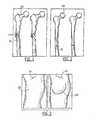
- FIG. 1is a side view of a fracture located on a distal end of a hip prosthesis
- FIG. 2is a side view of a fracture located distal to a hip prosthesis
- FIG. 3is a side view of a fracture located near to a knee prosthesis
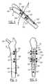
- FIG. 4is a perspective view of an embodiment of a fixation kit according to the invention.
- FIG. 5is a side view of the fixation kit of FIG. 4 ;
- FIG. 6is a front view of the fixation kit of FIG. 4 ;
- FIG. 7is a perspective view of a first embodiment of an attachment plate according to the invention.
- FIG. 8is a top view of the attachment plate of FIG. 7 ;
- FIG. 9is a front view of the attachment plate of FIG. 7 ;
- FIG. 10is a perspective view of a second embodiment of an attachment plate according to the invention.
- FIG. 11is cross-sectional view of the fixation kit of FIG. 4 ;
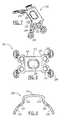
- FIG. 12is a perspective view of an embodiment of an aiming block according to the invention.
- FIG. 13Ais a side view of an embodiment of a fixation device according to the invention.
- FIG. 13Bis a cross-sectional view of the fixation device of FIG. 13A ;
- FIG. 13Cis a top view of the fixation device of FIG. 13A ;
- FIG. 13Dis a front view of a distal portion of the fixation device of FIG. 13A ;
- FIG. 14Ais a side view of a second embodiment of a fixation device according to the invention.
- FIG. 14Bis a cross-sectional view of the fixation device of FIG. 14A ;
- FIG. 14Cis a top view of the fixation device of FIG. 14A ;
- FIG. 14Dis a front view of a distal portion of the fixation device of FIG. 14A ;
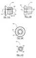
- FIG. 15Ais a cross-sectional view of a third embodiment of a fixation device according to the invention.
- FIG. 15Bis a top view of the fixation device of FIG. 15A ;
- FIG. 16Ais a cross-sectional view of a fourth embodiment of a fixation device according to the invention.
- FIG. 16Bis a top view of the fixation device of FIG. 16A ;
- FIG. 17Ais a cross-sectional view of a fifth embodiment of a fixation device according to the invention.
- FIG. 17Bis a top view of the fixation device of FIG. 17A ;
- FIG. 18Ais a cross-sectional view of a sixth embodiment of a fixation device according to the invention.
- FIG. 18Bis a top view of the fixation device of FIG. 18A .
- the present inventionmay be further understood with reference to the following description and to the appended drawings, wherein like elements are referred to with the same reference numerals.
- the present inventionrelates to devices for treatment of fractures.
- the inventionrelates to improved methods and systems for repairing periprosthetic fractures.
- exemplary embodiments of the present inventionwill be discussed with reference to knee and hip prostheses, the present invention may be successfully implemented in any long bone including a prosthetic device inserted into its medullary canal.
- the present inventionmay be used for the treatment of fractures around nails and for “conventional” fractures in patients with poor bone quality.
- the present inventionallows the user to apply standard fixation plates while placing screws and/or pins therethrough into the bone along paths selected to: 1) avoid any prosthesis in the medullary canal; 2) align the screws/pins non-parallel to one another to improve purchase in the bone; and/or 3) maximize the length of cancellous bone through which the screws/pins pass.
- Periprosthetic fracturesmay occur intraoperatively (during implantation or replacement of a prosthetic), or postoperatively (e.g., as a result of stress or trauma to the bone in which the prosthetic was previously implanted).
- fixation platese.g., dynamic compression plates (DCPs), locking compression plates (LCPs), etc.
- DCPsdynamic compression plates
- LCPslocking compression plates
- Periprosthetic fracturesare more difficult to treat than ordinary fractures because a prosthesis extending within the medullary canal may interfere with the proper coupling of a fixation plate across the fracture by preventing the fixation devices from being inserted through the bone across the medullary canal.
- hip prosthesesmay interfere with certain fractures of the femur. These hip prostheses often include a ball joint and a stem which is inserted into the medullary canal of the femur. As the femur absorbs significant stresses with each step, to adequately couple a fixation plate thereto, it is desired to maximize the purchase of the fixation devices in the femur.
- Type A fracturesare trochanteric (i.e., disposed at or near the greater or lesser trochanters); Type B fractures occur around the stem of the prosthesis; and Type C fractures occur so far from the stem that the fracture may be treated as a general fracture (i.e., the prosthesis may be ignored). Of these fractures, Type B is the most common.
- FIG. 1shows an example of a Type B fracture 50 located along a distal portion 110 of a hip prosthesis 100 .
- the present inventionmay also be used to treat general fractures (e.g., Type C fractures).
- An example of a Type C fractureis shown in FIG. 2 .
- FIG. 2shows a fracture 52 located distal of the hip prosthetic 100 .
- FIG. 3shows a treatable fracture 54 located near a knee prosthetic 130 .
- standard fixation platesare typically fixed by inserting one or more fixation devices (e.g., bone screws) substantially diametrically through the bone.
- fixation devicese.g., bone screws
- these fixation devicespass through the periosteum and compact bone adjacent to the fixation plate, through the medullary canal and then into the compact bone on the opposite side of the medullary canal.
- a prosthesisoccupies the medullary canal, inserting a screw directly therethrough is no longer possible and inserting the screw through only that portion of compact bone between the fixation plate and the medullary canal often does not provide sufficient anchorage.
- exemplary embodiments of fracture repair devices according to the present inventionenable the anchoring of screws or other fixation devices along extended paths through compact bone without contacting the prosthesis occupying the medullary canal.
- the devices and methods according to the present inventionmay also allow the user to customize the configuration and location of the fixation plate to achieve a desired fracture treatment.
- Exemplary embodiments of a fixation kit according to the present inventionwill now be described with reference to fracture repair devices designed to work in conjunction with any conventional fixation plate such as, for example, locking compression plates (LCPs).
- LCPslocking compression plates
- Exemplary embodiments of the fracture repair devicesmay be utilized in conjunction with any number of different types of LCPs or other fixation plates including, for example, an LCP broad curved plate, an LCP broad plate, an LCP Distal Femur (DF) plate, an LCP Less Invasive Stablization System (LISS) plate, an LCP proximal femur plate, an LCP proximal femur with hook plate, an LCP condylar plate, etc.
- LCP broad curved platean LCP broad plate
- DFDistal Femur
- LISSLCP Less Invasive Stablization System
- LCP proximal femur platean LCP proximal femur with hook plate
- LCP condylar plateetc.
- the exemplary fracture repair devicesmay also be used with other conventional fixation plates in addition to LCPs.
- the fixation platemay be selected to fit a specific situation in the same manner as would be done if there were no prosthesis or other reason for avoiding the insertion of fixation devices through the axis of the medullary canal.
- FIGS. 4-6show a fixation kit including an LCP 500 and two fracture repair devices 200 in place on a femur 10 .
- An intermedullary prosthesis 100(shown in hidden view) has been inserted into the medullary canal of the femur 10 and the LCP 500 extends proximally from a distal end 510 on a portion of the femur 10 distal of a distal end of the prosthesis 100 across a fracture to a proximal end 520 .
- Two devices 200are received over proximal and medial portions of the LCP 500 as these portions of the LCP 500 overlay the prosthesis 100 .
- the distal end 510may be secured to the femur in any conventional manner (e.g., by one or more bone screws inserted straight through the medullary canal and the compact bone on either side thereof).
- the size, configuration and/or location of the devices 200may vary depending on anatomy, fracture location and the position and/or size of a prosthesis relative to the LCP 500 .
- devices 200may be placed only where the LCP overlays a prosthesis, on both sides of a fracture regardless of location of the fracture relative to the LCP 500 or in any other desired arrangement so long as the required bond between the LCP 500 and the underlying bone is established.
- one or more additional devices 200may be attached to the distal end 510 of the LCP 500 or at any other locations to provide further stabilization.
- the LCP 500 of FIGS. 4-6extends distally beyond the distal end of the prosthesis 100 .
- a shorter LCPmay be selected with devices 200 providing support at all points along the length thereof.
- the number and the location of the devices 200may be determined according to physician preference. Therefore, in some embodiments the LCP 500 may be coupled to only a single device 200 (e.g., by centering the device 200 over the fracture) supplemented as desired by additional fixation devices including, for example, screws inserted only through the portion of compact bone adjacent to the LCP 500 .
- Each device 200is coupled to the LCP 500 via a screw 227 and includes one or more screws 257 or other fixation devices that anchor the device 200 to the bone 10 .
- a distal portion of the LCP 500extends beyond the prosthesis 100 and is anchored directly into the bone through the medullary canal as is done in the manner of general fractures, when no prosthesis is present.
- the distal portionmay be anchored using any number of screws 527 spaced in accordance with physician preference.
- Portions of the LCP 500 that extend along the length of the prosthesis 100either contain no screws that enter the medullary canal (e.g., portions not coupled to a device 200 ) or are secured via a device 200 , which is screwed (via the screws 257 ) at an angle into the bone 10 to avoid the prosthesis 100 .
- the device 200 shown in FIGS. 7-9is shaped for use in conjunction with the LCP 500 of FIGS. 4-6 .
- the device 200includes a locking attachment plate 202 formed of a substantially rigid biocompatible material such as, for example, plastic, medical-grade steel or titanium as would be understood by those skilled in the art.
- the attachment plate 202includes a body 210 including, on a bone-facing side thereof, a recess contoured to receive the LCP 500 . Sidewalls 215 of the recess may preferably be shaped to substantially conform to the contours of the LCP 500 .
- the body 210may also include a coupling feature that corresponds to a corresponding feature on the LCP 500 .
- the body 210may include a centrally located screw hole 225 that corresponds to a coupling arrangement (e.g., a threaded bore) of the LCP 500 .
- the body 210may be coupled to the LCP 500 by aligning the attachment plate 202 over to the LCP 500 and inserting a screw (e.g., the screw 227 ) or other fixation device through the hole 225 and into the threaded bore.
- the boremay pass through the entire body of the LCP 500 , enabling the screw 227 to extend past a bone-facing surface of the LCP 500 .
- the screw 227may be driven into the compact bone on the side of the medullary canal facing the LCP 500 without contacting the underlying intermedullary prosthesis.
- the screw 227may not extend past the LCP 500 , serving only to couple the LCP 500 and the device 200 .
- a fracture repair devicemay include a projection aligned to mate with a corresponding recess in an LCP (e.g., the threaded bore), a recess aligned to mate with a corresponding projection of an LCP or a combination of such recess/projection matings.
- the sidewalls 215may be snap-fit onto the LCP 500 .
- Other coupling arrangementssuch as, for example, friction-fitting, adhesives, bolts, etc. may also be used to couple the LCP 500 and the attachment plate 202 as would be understood by those skilled in the art.
- the attachment plate 202includes one or more arms 220 extending laterally from the sidewalls 215 , away from the body 210 .
- Each of the sidewalls 215includes an arm 220 extending from each end thereof and each of the arms 220 includes a first and a second screw hole 222 , 224 , respectively, extending therethrough.
- the arms 220may be formed integrally with the body 210 or attached separately.
- Each of the arms 220is preferably oriented such that a bone-facing surface of the arm 220 is generally follows the contours of a bone on which the arm 220 is to be mounted.
- the armsmay be formed of a material which may be bent by a user into a desired configuration to customize the arms 220 to the anatomy of each patient.
- each of the arms 220when viewed in a plane substantially perpendicular to a longitudinal axis of the medullary canal, each of the arms 220 extends along a curve substantially approximating the shape of an outer surface of a bone on which it is to be mounted.
- each arm 220also extends away from the corresponding side wall 215 at an angle within a plane of the body 210 .
- this angle and any change in this angle between the first and second screw holes 222 , 224allow for the application of additional screws at different angles and/or at different locations or, for example, to increase the area over which the attachment forces are applied to the bone.
- each of the arms 220includes a first screw hole 222 adjacent to the corresponding side wall 215 and a second screw hole 224 extending laterally away from the first screw hole 222 .
- each of the arms 220is shown extending at substantially the same angle, those skilled in the art will understand that the arms 220 may extend at different angles to accommodate varying bone structure, LCP shapes, etc. and may include the same number or different numbers of screw holes.
- the arms 220preferably curve to enable the arms 220 to wrap around the bone 10 in a substantially conforming manner.
- a degree to which the arms 220 encircle the bone 10may vary depending on the curvature and the angle of each arm 220 in relation to bone physiology.
- the arms 220may produce a tighter fit when mounted to wide portions of the bone 10 , while providing a looser fit when mounted to narrow bone portions.
- the arms 220may flex, allowing the arms 220 to be mounted closer to the bone 10 .
- Each of the first and second screw holes 222 , 224may be threaded to match a threading of a locking head of a screw 257 or may be otherwise suited to receive the particular fixation device to be employed with the device 200 .
- the number of screw holes in each arm 220may vary based on factors such as LCP shape, bone anatomy, desired degree of stabilization, etc.
- an exemplary attachment plate 302is substantially similar to the plate 202 of FIGS. 7-9 except that each of the arms 320 has only one screw hole 250 extending therethrough. It will be understood by those of skill in the art that the attachment plate 302 may be used according to the device 200 in substantially the same manner as the attachment plate 202 .
- one or more armsmay not include any holes at all or may contain more than two screw holes.
- Each of the holes 250defines an angle of insertion for the screw 257 selected so that when the attachment plate 202 is mounted onto the bone 10 , the screw 257 passes through the bone 10 without diametrically passing through the medullary canal, thereby avoiding contact with the prosthesis 100 .
- the angleis preferably selected to maximize the length of the screw 257 received in the bone 10 .
- some or all of the screw holes for any of the attachment plates according to the inventionmay be variable angle locking holes allowing for locking screws to be inserted therethrough and locked to the plate at multiple angles relative to the attachment plate.
- any or all of the screw holes 222 , 224 and 250may be formed substantially in accord with the description in U.S. Patent Application Publication No. 2005/0165400 filed by Fernandez, Jul. 28, 2005, the entire disclosure of which is hereby incorporated by reference in its entirety.
- the screwsmay have a head shaped like a sphere and threaded with a substantially constant pitch substantially equal to a pitch of a threaded shank of the screw.
- an insertion/extraction holemay be cut in the head for the connection of an insertion/extraction tool.
- the thread cut in the screw headmay have a double entry maintaining substantially the same pitch as that of the thread of the shank.
- the thread profilemay vary according to the requirements and according to the mechanical properties of the material of which the screw is formed.
- such a screw holemay be formed in a spherical shape, with edges thereof at both ends of the hole removed in a frusto-conical shape. That is, the screw hole may include two frusto-conical portions extending toward one another from opposite surfaces of the plate and connected at tips of the cones through a partial sphere.
- the inner wall of each screw holehas a small number of isolated protrusions such as pegs or spikes (e.g., between two and thirty) designed to lock against the threaded spherical head of the screws when the screws are driven in through the screw holes.
- the protrusionsmay, for example, be somewhat flattened with a width bigger than its length.
- the spherical shape of the screw headallows it to lock against the protrusions without regard to whether the screw extends perpendicular or at a tilt relative to an axis of the screw hole.
- the angle at which of the screw is lockedmay then be varied by as much as 20° relative to the axis of the screw hole.
- a physicianmay begin treatment by selecting an LCP 500 of appropriate size and shape, taking into account the width of the bone 10 , the location of the fracture and other factors as would be understood by those skilled in the art.
- the LCP 500is then aligned over the bone 10 to extend across the fracture in a position selected to stabilize the portions of the bone on both sides thereof.
- the physicianthen has the option of initially securing the distal portion of the LCP 500 to the portion of the bone not including a prosthesis within the medullary canal or of selecting one or more attachment plates 202 to achieve the desired coupling of the LCP 500 and the proximal portion of the bone.
- the physiciandrives the screws 527 directly into the bone 10 in the same manner as would be used for a fracture where no prosthesis was present. Thereafter, the physician may slide the selected plate 202 over the proximal portion of the LCP 500 to the desired alignment and attach the plate 202 to the LCP 500 .
- the physicianmay attach the attachment plate to the bone in a desired location before attaching the LCP 500 to either the plate 202 or any portion of the bone and then slide the LCP 500 through the recess into place between the bone 10 and the attachment plate 202 .
- the physicianmay choose to couple the attachment plate 202 to the LCP 500 before attaching the attachment plate 202 to the bone 10 .
- the attachment plate 202is positioned over a desired location of the LCP 500 .
- the LCP 500includes multiple attachment arrangements comprising attachment sites 507 located along the entire length thereof.
- the attachment sites 507are spaced apart, either uniformly or at different distances. For example, certain lengths of the LCP 500 may include more attachment sites (i.e., tighter spacing) than others.
- the attachment sites 507may correspond to anchoring locations of the screws 227 .
- the attachment arrangementsmay be the same as the holes through which the screws 527 may be driven although, as would be understood, the screws are used to couple the attachment plate 202 to the LCP 500 will be shorter than those used to directly couple the LCP 500 to the bone so as to avoid interference with the intermedullary prosthesis.
- the attachment plate 202is coupled to the LCP 500 by either driving the screw 227 to a depth beyond the bone-facing surface of the LCP 500 (i.e., into the bone 10 ) or to a depth within the body of the LCP 500 .
- the couplingmay occur prior to introduction of the LCP 500 into the patient.
- the attachment plate 202is then anchored to the bone 10 by individually driving each screw 257 into the bone 10 at an angle selected by the physician (e.g., to maximize a length of the path the screw travels through the compact bone without entering the medullary canal).
- the bone 10 beneath each hole 250is drilled out to a desired depth (e.g., a maximum depth of penetration of the compact bone without contacting the prosthesis 100 ).
- a desired depthe.g., a maximum depth of penetration of the compact bone without contacting the prosthesis 100 .
- the screws 257may be self-tapping.
- the maximum depth to which the screws 257 may be drivenis a function of known factors such as, for example, bone anatomy and the available insertion angles.
- FIG. 12shows an exemplary embodiment of an aiming block 400 in an operative position.
- the aiming block 400which may be placed over the attachment plate 202 or over the combined attachment plate-LCP, includes a body portion 410 including a hole 425 matching the hole 225 .
- the hole 425is not strictly required, including the hole 425 facilitates visual confirmation that the aiming block 400 has been placed correctly over the attachment plate 202 .
- the aiming block 400is placed on top of the attachment plate 202 and aligned therewith.
- the aiming block 400includes one or more shafts 450 corresponding to the first hole 222 and/or the second hole 224 .
- the shafts 450are positioned at desired angles to form a drilling template.
- a plurality of aiming blocks 400 with different shaft configurationsmay be available for use, enabling the drilled holes to be oriented at any desired angle.
- a drilling toolis inserted through a hole 455 located at one end of the shaft 450 and guided through an opening at the opposite end of the shaft 450 into either of the first hole 222 and the second hole 224 and, subsequently, into the bone 10 . After reaching the desired drilling depth, the drilling tool is withdrawn from the shaft and additional holes may be created by inserting the drilling tool into further shafts 450 .
- the aiming block 400is removed and the operating site is cleared of bone debris before inserting the screws 257 .
- the screws 257may then be inserted directly into the first and/or the second holes 222 , 224 or guided through the shafts 450 of the aiming block 400 .
- a substantial portion of each screw 257occupies the bone cortex 15 without interfering with a prosthesis 100 within the medullary canal 12 .
- Screws of varying lengthmay be provided as part of the fixation kit to take advantage of the maximum allowable insertion depth.
- the screwsmay be selected to extend from one side of the bone 10 to an opposing side. As seen in FIG.
- the screws 257may also occupy a portion of a medullary canal 12 without passing diametrically therethrough or contacting the prosthesis 100 .
- the arms 220may be drawn toward the bone 10 by pressure exerted by head portions of the screws 257 .
- a close fitis desired for stability, it may also be desirable not to excessively constrict the bone 10 or the blood supply thereto by drawing the arms 220 too tightly thereagainst.
- a small gap 60may be left between the arms 220 and the bone 10 . The gap 60 promotes blood flow and reduces the amount of bone compressed by the attachment plate 202 .
- the gap 60may be achieved by forming the arms 220 with sufficient curvature such that a bone-facing surface of the arms 220 is substantially concave.
- the gap 60may also be a function of the extent to which the screws 257 are driven into the bone 10 . If a smaller gap is desired, more of the screw 257 can be driven in. Similarly, less driving will result in a larger gap. Thus, the length of a shaft portion 259 of each screw 257 that is exposed within the gap 60 is variable. Some screws 257 may be driven entirely into the bone 10 while other screws 257 may form large gaps.
- FIGS. 13A-13Dshow an exemplary embodiment of a screw 557 according to the present invention.
- the screw 557includes a conical body comprising a head 552 and a shaft 554 including a plurality of threads 555 .
- the shaft 554also includes one or more slots 559 extending substantially the entire length thereof.
- the conical body of the screw 557tapers from the head 552 toward the shaft 554 .
- FIG. 13Bshows a cross-section of the screw 557 , taken along line B-B. As shown, a portion of the head 552 includes a recess 532 .
- the recess 532is hex-shaped.
- the shape of the recess 532is shown more clearly in the top view of the head 552 illustrated in FIG. 13C .
- the exemplary embodimentutilizes a hex-shaped recess, other shapes (e.g., stars or triangles) may be utilized in other embodiments.
- FIG. 13Dshows a front view of a distal tip 590 of the screw 557 .
- the slots 559are equidistantly spaced about the perimeter of the distal tip 590 .
- the screwsmay be formed of stainless steel, titanium or a suitable biocompatible polymer.
- FIGS. 14A-14Dshow an exemplary embodiment of a screw 657 according to the present invention.
- the screw 657includes a cylindrical body comprising a head 652 and a shaft 654 including a plurality of threads 655 .
- the shaft 654also includes one or more slots 659 extending substantially the entire length thereof.
- FIG. 14Bshows a cross-section of the screw 657 .
- a portion of the head 652includes a recess 632 .
- the recess 632is hex-shaped.
- FIG. 14Dshows a front view of a distal tip 690 of the screw 657 .
- the slots 659are equidistantly spaced about the perimeter of the distal tip 690 .
- FIGS. 15A and 15Bshow an exemplary embodiment of a screw 757 according to the present invention.
- the screw 757includes an outer member 752 and an inner member 754 that couples to the outer member 752 .
- the inner member 754extends substantially the entire length of the outer member 752 and includes a hex-shaped recess 732 .
- An inner wall 710 of the outer member 752defines an interface shaped to mate with the inner member 754 using friction-fitting.
- the inner member 754may be coupled to the outer member 752 in any number of ways including, for example, screwing in a direction opposite to that of threads 75 running along an outer surface of the outer member 752 .
- FIGS. 16A and 16Bshow an exemplary embodiment of a peg 857 according to the present invention.
- the peg 857includes an outer member 852 and an inner member 854 that couples to the outer member 852 .
- the inner member 854extends substantially the entire length of a head portion 856 of the outer member 852 and includes a hex-shaped recess 832 .
- a distal end 834 of the inner member 854is shaped to conform to the contours of the head 856 .
- An inner wall 810 of the outer member 852defines an interface shaped to mate with the inner member 854 using friction-fitting.
- the inner member 854may be coupled to the outer member 852 in any number of ways including, for example, screwing.
- FIGS. 17A and 17Bshow an exemplary embodiment of a peg 957 according to the present invention.
- the peg 957includes an outer member 952 and an inner member 954 that couples to the outer member 952 .
- the inner member 954extends substantially the entire length of the outer member 952 and includes a hex-shaped recess 932 .
- the outer member 952includes a head portion 956 and a shaft portion 958 having a diameter less than that of the head 956 .
- An inner wall 910 of the outer member 952defines an interface shaped to mate with the inner member 954 using friction-fitting.
- the inner member 954may be coupled to the outer member 952 in any number of ways including, for example, screwing.
- FIGS. 18A and 18Bshow an exemplary embodiment of a screw 1057 according to the present invention.
- the screw 1057includes an outer member 1052 and an inner member 1054 that couples to the outer member 1052 .
- the inner member 1054extends substantially the entire length of a head portion 1056 of the outer member 1052 and includes a hex-shaped recess 1032 .
- the outer member 1052includes a head portion 1056 and a shaft portion 1058 having a diameter greater than that of the head 1056 .
- a distal end 1034 of the inner member 1054is conically shaped.
- An inner wall 1010 of the outer member 1052defines an interface shaped to mate with the inner member 1054 using friction-fitting.
- the inner member 1054may be coupled to the outer member 1052 in any number of ways including, for example, screwing in a direction opposite to that of threads 85 running along an outer surface of the outer member 1052 .
Landscapes
- Health & Medical Sciences (AREA)
- Orthopedic Medicine & Surgery (AREA)
- Surgery (AREA)
- Life Sciences & Earth Sciences (AREA)
- Heart & Thoracic Surgery (AREA)
- Nuclear Medicine, Radiotherapy & Molecular Imaging (AREA)
- Engineering & Computer Science (AREA)
- Biomedical Technology (AREA)
- Neurology (AREA)
- Medical Informatics (AREA)
- Molecular Biology (AREA)
- Animal Behavior & Ethology (AREA)
- General Health & Medical Sciences (AREA)
- Public Health (AREA)
- Veterinary Medicine (AREA)
- Surgical Instruments (AREA)
- Prostheses (AREA)
Abstract
Description
Claims (23)
Priority Applications (1)
| Application Number | Priority Date | Filing Date | Title |
|---|---|---|---|
| US12/740,074US9788872B2 (en) | 2007-11-13 | 2008-11-05 | Periprosthetic fracture repair |
Applications Claiming Priority (3)
| Application Number | Priority Date | Filing Date | Title |
|---|---|---|---|
| US98756007P | 2007-11-13 | 2007-11-13 | |
| US12/740,074US9788872B2 (en) | 2007-11-13 | 2008-11-05 | Periprosthetic fracture repair |
| PCT/US2008/082470WO2009064643A1 (en) | 2007-11-13 | 2008-11-05 | Periprosthetic fracture repair |
Publications (2)
| Publication Number | Publication Date |
|---|---|
| US20100262194A1 US20100262194A1 (en) | 2010-10-14 |
| US9788872B2true US9788872B2 (en) | 2017-10-17 |
Family
ID=40243955
Family Applications (1)
| Application Number | Title | Priority Date | Filing Date |
|---|---|---|---|
| US12/740,074Active2032-05-29US9788872B2 (en) | 2007-11-13 | 2008-11-05 | Periprosthetic fracture repair |
Country Status (12)
| Country | Link |
|---|---|
| US (1) | US9788872B2 (en) |
| EP (1) | EP2211741B1 (en) |
| JP (1) | JP5580203B2 (en) |
| KR (1) | KR101554921B1 (en) |
| CN (1) | CN101854873B (en) |
| AU (1) | AU2008321211A1 (en) |
| BR (1) | BRPI0820212B8 (en) |
| CA (1) | CA2705446C (en) |
| CO (1) | CO6280609A2 (en) |
| ES (1) | ES2424446T3 (en) |
| PL (1) | PL2211741T3 (en) |
| WO (1) | WO2009064643A1 (en) |
Cited By (5)
| Publication number | Priority date | Publication date | Assignee | Title |
|---|---|---|---|---|
| US20210338291A1 (en)* | 2020-05-04 | 2021-11-04 | Laboratoires Bodycad Inc. | Osteotomy plate and method for performing an osteotomy procedure using the same |
| US20220361931A1 (en)* | 2011-05-10 | 2022-11-17 | DePuy Synthes Products, Inc. | Bone Fracture Fixation Clamp |
| US20230056989A1 (en)* | 2021-08-17 | 2023-02-23 | Edward Perez | Bone fixation devices, systems, and methods |
| US12232749B2 (en)* | 2018-02-27 | 2025-02-25 | Zimmer, Inc. | Drill guide for orthopedic device |
| US12408956B2 (en) | 2023-02-21 | 2025-09-09 | DePuy Synthes Products, Inc. | Bone plates, and related systems and methods |
Families Citing this family (49)
| Publication number | Priority date | Publication date | Assignee | Title |
|---|---|---|---|---|
| US20090228010A1 (en) | 2008-03-10 | 2009-09-10 | Eduardo Gonzalez-Hernandez | Bone fixation system |
| AU2008354730A1 (en) | 2008-04-17 | 2009-10-22 | Toby Orthopaedics, Inc. | Soft tissue attachment system and clip |
| US9956014B2 (en)* | 2010-09-20 | 2018-05-01 | DePuy Synthes Products, Inc. | Method for joining two or more segments of a surgical implant |
| US8961573B2 (en) | 2010-10-05 | 2015-02-24 | Toby Orthopaedics, Inc. | System and method for facilitating repair and reattachment of comminuted bone portions |
| US8518042B2 (en)* | 2010-10-19 | 2013-08-27 | Biomet Manufacturing, Llc | Orthopedic plate assembly for a distal radius having re-contouring features and method for using same |
| WO2012058448A2 (en) | 2010-10-27 | 2012-05-03 | Toby Orthopaedics, Llc | System and method for fracture replacement of comminuted bone fractures or portions thereof adjacent bone joints |
| US8709092B2 (en) | 2011-02-16 | 2014-04-29 | Genesis Medical Devices, LLC | Periprosthetic fracture management enhancements |
| US20120226321A1 (en)* | 2011-03-03 | 2012-09-06 | Eduardo Gonzalez-Hernandez | Modular and non-modular cortical buttress device |
| WO2012119146A2 (en) | 2011-03-03 | 2012-09-07 | Toby Orthopaedics, Llc | Anterior lesser tuberosity fixed angle fixation device and method of use associated therewith |
| WO2013036582A1 (en)* | 2011-09-06 | 2013-03-14 | Skeletal Dynamics, L.L.C. | Fracture fixation plate, system and methods of use |
| US9271772B2 (en) | 2011-10-27 | 2016-03-01 | Toby Orthopaedics, Inc. | System and method for fracture replacement of comminuted bone fractures or portions thereof adjacent bone joints |
| US9730797B2 (en) | 2011-10-27 | 2017-08-15 | Toby Orthopaedics, Inc. | Bone joint replacement and repair assembly and method of repairing and replacing a bone joint |
| US9402667B2 (en) | 2011-11-09 | 2016-08-02 | Eduardo Gonzalez-Hernandez | Apparatus and method for use of the apparatus for fracture fixation of the distal humerus |
| US9681902B2 (en) | 2012-02-13 | 2017-06-20 | Stryker European Holdings I, Llc | Attachment device for a bone plate |
| US8998904B2 (en) | 2012-07-17 | 2015-04-07 | Fastforward Surgical Inc. | Winged tether plate and method of use for reducing angular bone deformity |
| US9480475B2 (en)* | 2012-08-15 | 2016-11-01 | DePuy Synthes Products, Inc. | Bone plate suture anchor |
| US9283008B2 (en) | 2012-12-17 | 2016-03-15 | Toby Orthopaedics, Inc. | Bone plate for plate osteosynthesis and method for use thereof |
| US9138244B2 (en) | 2013-02-27 | 2015-09-22 | Biomet C.V. | Dynamic compression plate |
| US9138245B2 (en) | 2013-02-27 | 2015-09-22 | Biomet C.V. | Jig with guide adapted to lock relative to both of threaded holes and non-threaded slots in a bone plate |
| US9131968B2 (en) | 2013-02-27 | 2015-09-15 | Biomet C.V. | Periprosthetic plating system including plate with system for retaining tension on a cable |
| US9138267B2 (en) | 2013-02-27 | 2015-09-22 | Biomet C.V. | Periprosthetic plating system with compressive plate and transverse bridge plate |
| US9138268B2 (en) | 2013-02-27 | 2015-09-22 | Biomet C.V. | Periprosthetic fracture repair system including discrete stabilized crimp lugs for cerclage cable and tool therefor |
| US9333014B2 (en) | 2013-03-15 | 2016-05-10 | Eduardo Gonzalez-Hernandez | Bone fixation and reduction apparatus and method for fixation and reduction of a distal bone fracture and malunion |
| DE102013104887B4 (en) | 2013-05-13 | 2021-03-18 | Aap Implantate Ag | Osteosynthesis plate and segment for an osteosynthesis plate |
| CN103536347A (en)* | 2013-05-28 | 2014-01-29 | 广州军区广州总医院 | Auxiliary wing type steel plate |
| EP3021773B1 (en)* | 2013-07-16 | 2018-11-07 | Fastforward Surgical Inc. | Bone plate for reducing angular bone deformity |
| CN103494638A (en)* | 2013-10-14 | 2014-01-08 | 天津正天医疗器械有限公司 | Bone fracture plate with auxiliary fixing device |
| CN103610492A (en)* | 2013-11-26 | 2014-03-05 | 胡宁敏 | Adjustable special-shaped proximal femur locking plate |
| JP6562595B2 (en)* | 2014-05-21 | 2019-08-21 | ディトマール・ヴォルター | Osteosynthesis system for multi-directional, angle-stable treatment of tubular fractures with intramedullary nails and bone screws |
| JP6562596B2 (en)* | 2014-05-21 | 2019-08-21 | ディトマール・ヴォルター | Osteosynthesis system for multi-directional, angle-stable treatment of tubular fractures with intramedullary nails and bone screws |
| CN104224293A (en)* | 2014-08-31 | 2014-12-24 | 中国人民解放军广州军区武汉总医院 | Combined internal fixator for fixing laparoscopic gastric banding |
| US10213237B2 (en) | 2014-10-03 | 2019-02-26 | Stryker European Holdings I, Llc | Periprosthetic extension plate |
| US9463053B2 (en) | 2014-12-08 | 2016-10-11 | Jonathan P. GARINO | Fracture plating |
| US10314626B2 (en) | 2015-01-16 | 2019-06-11 | DePuy Synthes Procucts, Inc. | Washer plate |
| US9962192B2 (en)* | 2016-03-17 | 2018-05-08 | Medos International Sarl | Multipoint fixation implants |
| US10251685B2 (en) | 2016-03-17 | 2019-04-09 | Stryker European Holdings I, Llc | Floating locking insert |
| US10172645B2 (en) | 2016-05-20 | 2019-01-08 | Fastforward Surgical Inc. | Method of correcting hallux varus joint deformity |
| CN106037902A (en)* | 2016-07-07 | 2016-10-26 | 周健 | Proximal periprosthetic femoral fracture external fixation plate |
| EP3522802B1 (en)* | 2016-10-07 | 2024-10-23 | Acumed LLC | System for bone fixation using a plate straddled by a retainer |
| JP2020509863A (en)* | 2017-03-13 | 2020-04-02 | デピュイ・シンセス・プロダクツ・インコーポレイテッド | Proximal femoral plate system |
| CN106937882B (en)* | 2017-04-21 | 2023-11-24 | 廊坊市人民医院 | A bone plate with titanium cable and auxiliary positioning device |
| US10898232B2 (en) | 2018-03-20 | 2021-01-26 | Medos International Sàrl | Multipoint fixation implants and related methods |
| US11272968B2 (en) | 2018-10-03 | 2022-03-15 | DePuy Synthes Products, Inc. | Slotted periprosthetic plate for variable angle holes |
| CN110522500A (en)* | 2019-09-23 | 2019-12-03 | 昆明医科大学第二附属医院 | A combined lower tibiofibular syndesmosis fixation plate |
| US11426210B2 (en) | 2019-09-25 | 2022-08-30 | Medos International Sàrl | Multipoint angled fixation implants for multiple screws and related methods |
| EP4103083B1 (en) | 2020-02-14 | 2024-10-23 | Medos International Sàrl | Integrated multipoint fixation screw |
| EP4342398A3 (en) | 2020-05-19 | 2024-05-29 | Smith & Nephew, Inc. | Periprosthetic bone plate |
| US11452552B1 (en)* | 2021-05-07 | 2022-09-27 | Avanti Orthopaedics Llc | Augmented spanning fixation bone plate assembly |
| CN115399860B (en)* | 2022-07-04 | 2025-03-07 | 广州赛隆增材制造有限责任公司 | Medical internal fixing device |
Citations (37)
| Publication number | Priority date | Publication date | Assignee | Title |
|---|---|---|---|---|
| US3824995A (en) | 1972-07-24 | 1974-07-23 | Villiers E | Trochanteric plate |
| US4120298A (en) | 1976-12-06 | 1978-10-17 | Fixel Irving E | Implant to secure the greater trochanter |
| US4263904A (en) | 1978-02-10 | 1981-04-28 | Judet Robert L | Osteosynthesis devices |
| DE3006518A1 (en) | 1980-02-19 | 1981-08-27 | Mecron Medizinische Produkte Gmbh, 1000 Berlin | DEVICE FOR FIXING A THIGH NECK ON THE SHAFT OF A THIGH BONE |
| US4506662A (en) | 1981-06-18 | 1985-03-26 | Mecron Medizinische Produkte Gmbh | Nail for fixing a fracture of the femur |
| US4565193A (en) | 1982-09-13 | 1986-01-21 | Elke Streli | Pronged plate for resetting fractured bones |
| JPH02211141A (en) | 1989-02-10 | 1990-08-22 | Dan Sangyo Kk | Inner splint for fixing broken bone part |
| US4973332A (en) | 1988-09-12 | 1990-11-27 | Hospital For Joint Diseases | Attachment for femur sliding screw plate |
| SU1634260A1 (en) | 1987-06-19 | 1991-03-15 | Московский медицинский стоматологический институт им.Н.А.Семашко | Appliance for osteosynthesis of the intertrochanteric space |
| US5015248A (en) | 1990-06-11 | 1991-05-14 | New York Society For The Relief Of The Ruptured & Crippled, Maintaining The Hospital For Special Surgery | Bone fracture fixation device |
| US5120171A (en)* | 1990-11-27 | 1992-06-09 | Stuart Surgical | Bone screw with improved threads |
| US5151103A (en)* | 1987-11-03 | 1992-09-29 | Synthes (U.S.A.) | Point contact bone compression plate |
| JPH0546460A (en) | 1991-08-20 | 1993-02-26 | Oki Electric Ind Co Ltd | Instruction processing system |
| JPH06505423A (en) | 1991-12-13 | 1994-06-23 | ペニヒ ディートマル | Bone attachment aid for trochanteric fractures of the femoral neck |
| EP0615728A2 (en) | 1993-02-16 | 1994-09-21 | MIKHAIL, Michael W.E. | Orthopaedic reconstruction plate |
| FR2712173A1 (en) | 1993-11-10 | 1995-05-19 | Fleuriau Chateau Joseph | Support plate assembly for fractured bone, e.g. trochanter |
| US5462547A (en) | 1991-05-30 | 1995-10-31 | Synthes (U.S.A.) | Trochanter stabilization device |
| JPH08299361A (en) | 1995-05-10 | 1996-11-19 | Oyo Kagaku Kenkyusho | Bone reduction and fixing plate structure body |
| US5591168A (en) | 1993-10-25 | 1997-01-07 | Tornier S.A. | Device for stabilizing fractures of the upper end of the femur |
| GB2331244A (en) | 1997-11-18 | 1999-05-19 | Univ Hull | Fracture fixation devices |
| US5973223A (en) | 1994-02-21 | 1999-10-26 | Collux Ab | Implant for fixing femoral fractures |
| GR1003502B (en) | 1999-04-26 | 2001-01-03 | Plate for the retention of fractures of the major trochanter | |
| US6338734B1 (en) | 2000-03-14 | 2002-01-15 | Biomet, Inc. | Method and apparatus for trochanter fixation |
| US6503281B1 (en) | 2000-08-25 | 2003-01-07 | Thomas H. Mallory | Total hip replacement |
| US6652530B2 (en) | 2001-09-19 | 2003-11-25 | The University Of Hong Kong | Fixation device |
| US20040030339A1 (en)* | 2001-04-20 | 2004-02-12 | Wack Michael A. | Dual locking plate and associated method |
| US6755831B2 (en)* | 2001-11-30 | 2004-06-29 | Regents Of The University Of Minnesota | Wrist surgery devices and techniques |
| US20040225291A1 (en) | 2003-04-01 | 2004-11-11 | Andy Schwammberger | Implant |
| US20040236337A1 (en) | 2003-04-02 | 2004-11-25 | Benoist Girard Sas | Greater trochanteric re-attachment device |
| US20050049595A1 (en) | 2003-09-03 | 2005-03-03 | Suh Sean S. | Track-plate carriage system |
| US20050101959A1 (en) | 2000-11-22 | 2005-05-12 | Milorad Mitkovic | Internal fixator of bones |
| US20050240187A1 (en) | 2004-04-22 | 2005-10-27 | Huebner Randall J | Expanded fixation of bones |
| WO2006097729A1 (en) | 2005-03-17 | 2006-09-21 | Desmond Meiring Dall | Configurable bone fixation system |
| US20060217722A1 (en) | 2003-09-08 | 2006-09-28 | Christof Dutoit | Bone-fixation device |
| US7229444B2 (en) | 2004-08-25 | 2007-06-12 | Howmedica Osteonics Corp. | Trochanteric cerclage plate |
| US7306600B2 (en)* | 2001-10-17 | 2007-12-11 | Synthes (U.S.A.) | Bone fixation system |
| US20080103501A1 (en)* | 2006-08-11 | 2008-05-01 | Ralph Christopher R | Angled Washer Polyaxial Connection for Dynamic Spine Prosthesis |
Family Cites Families (11)
| Publication number | Priority date | Publication date | Assignee | Title |
|---|---|---|---|---|
| US615728A (en)* | 1898-12-13 | Alfonb mauser | ||
| US2630A (en)* | 1842-05-20 | Mabia p | ||
| US1003502A (en)* | 1908-05-11 | 1911-09-19 | Arthur F Poole | Frequency-meter. |
| US934731A (en)* | 1908-11-25 | 1909-09-21 | William E Jenkins | Transmission-gearing. |
| US1599483A (en)* | 1925-05-22 | 1926-09-14 | Leeds & Northrup Co | Ion concentration cell |
| US1634260A (en)* | 1926-07-17 | 1927-07-05 | Langdon C Kellogg | Mop |
| US2331244A (en)* | 1940-12-07 | 1943-10-05 | Standard Oil Dev Co | Refining mineral oils |
| US2712173A (en)* | 1954-05-06 | 1955-07-05 | Clifford W Denner | Method of making finger rings |
| US3006518A (en)* | 1958-11-24 | 1961-10-31 | William W Lillard | Needle threaders |
| US5855302A (en)* | 1996-12-18 | 1999-01-05 | Georgia-Pacific Corporation | Liquid dispensing cap valve assembly with pedestal mounted resilient valve seal element |
| US7095239B2 (en)* | 2004-11-09 | 2006-08-22 | Hitachi Global Storage Technologies Netherlands B.V. | Method for detecting defects that exhibit repetitive patterns |
- 2008
- 2008-11-05CNCN2008801159272Apatent/CN101854873B/enactiveActive
- 2008-11-05USUS12/740,074patent/US9788872B2/enactiveActive
- 2008-11-05CACA2705446Apatent/CA2705446C/enactiveActive
- 2008-11-05BRBRPI0820212Apatent/BRPI0820212B8/enactiveIP Right Grant
- 2008-11-05KRKR1020107010403Apatent/KR101554921B1/enactiveActive
- 2008-11-05EPEP08850458.4Apatent/EP2211741B1/enactiveActive
- 2008-11-05ESES08850458Tpatent/ES2424446T3/enactiveActive
- 2008-11-05PLPL08850458Tpatent/PL2211741T3/enunknown
- 2008-11-05AUAU2008321211Apatent/AU2008321211A1/ennot_activeAbandoned
- 2008-11-05WOPCT/US2008/082470patent/WO2009064643A1/enactiveApplication Filing
- 2008-11-05JPJP2010533211Apatent/JP5580203B2/enactiveActive
- 2010
- 2010-06-11COCO10070853Apatent/CO6280609A2/ennot_activeApplication Discontinuation
Patent Citations (38)
| Publication number | Priority date | Publication date | Assignee | Title |
|---|---|---|---|---|
| US3824995A (en) | 1972-07-24 | 1974-07-23 | Villiers E | Trochanteric plate |
| US4120298A (en) | 1976-12-06 | 1978-10-17 | Fixel Irving E | Implant to secure the greater trochanter |
| US4263904A (en) | 1978-02-10 | 1981-04-28 | Judet Robert L | Osteosynthesis devices |
| DE3006518A1 (en) | 1980-02-19 | 1981-08-27 | Mecron Medizinische Produkte Gmbh, 1000 Berlin | DEVICE FOR FIXING A THIGH NECK ON THE SHAFT OF A THIGH BONE |
| US4506662A (en) | 1981-06-18 | 1985-03-26 | Mecron Medizinische Produkte Gmbh | Nail for fixing a fracture of the femur |
| US4565193A (en) | 1982-09-13 | 1986-01-21 | Elke Streli | Pronged plate for resetting fractured bones |
| SU1634260A1 (en) | 1987-06-19 | 1991-03-15 | Московский медицинский стоматологический институт им.Н.А.Семашко | Appliance for osteosynthesis of the intertrochanteric space |
| US5151103A (en)* | 1987-11-03 | 1992-09-29 | Synthes (U.S.A.) | Point contact bone compression plate |
| US4973332A (en) | 1988-09-12 | 1990-11-27 | Hospital For Joint Diseases | Attachment for femur sliding screw plate |
| JPH02211141A (en) | 1989-02-10 | 1990-08-22 | Dan Sangyo Kk | Inner splint for fixing broken bone part |
| US5015248A (en) | 1990-06-11 | 1991-05-14 | New York Society For The Relief Of The Ruptured & Crippled, Maintaining The Hospital For Special Surgery | Bone fracture fixation device |
| US5120171A (en)* | 1990-11-27 | 1992-06-09 | Stuart Surgical | Bone screw with improved threads |
| US5462547A (en) | 1991-05-30 | 1995-10-31 | Synthes (U.S.A.) | Trochanter stabilization device |
| JPH0546460A (en) | 1991-08-20 | 1993-02-26 | Oki Electric Ind Co Ltd | Instruction processing system |
| JPH06505423A (en) | 1991-12-13 | 1994-06-23 | ペニヒ ディートマル | Bone attachment aid for trochanteric fractures of the femoral neck |
| EP0615728A2 (en) | 1993-02-16 | 1994-09-21 | MIKHAIL, Michael W.E. | Orthopaedic reconstruction plate |
| US5591168A (en) | 1993-10-25 | 1997-01-07 | Tornier S.A. | Device for stabilizing fractures of the upper end of the femur |
| FR2712173A1 (en) | 1993-11-10 | 1995-05-19 | Fleuriau Chateau Joseph | Support plate assembly for fractured bone, e.g. trochanter |
| US5973223A (en) | 1994-02-21 | 1999-10-26 | Collux Ab | Implant for fixing femoral fractures |
| JPH08299361A (en) | 1995-05-10 | 1996-11-19 | Oyo Kagaku Kenkyusho | Bone reduction and fixing plate structure body |
| GB2331244A (en) | 1997-11-18 | 1999-05-19 | Univ Hull | Fracture fixation devices |
| EP0934731A1 (en) | 1997-11-18 | 1999-08-11 | The University of Hull | Bone fracture fixation devices |
| GR1003502B (en) | 1999-04-26 | 2001-01-03 | Plate for the retention of fractures of the major trochanter | |
| US6338734B1 (en) | 2000-03-14 | 2002-01-15 | Biomet, Inc. | Method and apparatus for trochanter fixation |
| US6503281B1 (en) | 2000-08-25 | 2003-01-07 | Thomas H. Mallory | Total hip replacement |
| US20050101959A1 (en) | 2000-11-22 | 2005-05-12 | Milorad Mitkovic | Internal fixator of bones |
| US20040030339A1 (en)* | 2001-04-20 | 2004-02-12 | Wack Michael A. | Dual locking plate and associated method |
| US6652530B2 (en) | 2001-09-19 | 2003-11-25 | The University Of Hong Kong | Fixation device |
| US7306600B2 (en)* | 2001-10-17 | 2007-12-11 | Synthes (U.S.A.) | Bone fixation system |
| US6755831B2 (en)* | 2001-11-30 | 2004-06-29 | Regents Of The University Of Minnesota | Wrist surgery devices and techniques |
| US20040225291A1 (en) | 2003-04-01 | 2004-11-11 | Andy Schwammberger | Implant |
| US20040236337A1 (en) | 2003-04-02 | 2004-11-25 | Benoist Girard Sas | Greater trochanteric re-attachment device |
| US20050049595A1 (en) | 2003-09-03 | 2005-03-03 | Suh Sean S. | Track-plate carriage system |
| US20060217722A1 (en) | 2003-09-08 | 2006-09-28 | Christof Dutoit | Bone-fixation device |
| US20050240187A1 (en) | 2004-04-22 | 2005-10-27 | Huebner Randall J | Expanded fixation of bones |
| US7229444B2 (en) | 2004-08-25 | 2007-06-12 | Howmedica Osteonics Corp. | Trochanteric cerclage plate |
| WO2006097729A1 (en) | 2005-03-17 | 2006-09-21 | Desmond Meiring Dall | Configurable bone fixation system |
| US20080103501A1 (en)* | 2006-08-11 | 2008-05-01 | Ralph Christopher R | Angled Washer Polyaxial Connection for Dynamic Spine Prosthesis |
Cited By (7)
| Publication number | Priority date | Publication date | Assignee | Title |
|---|---|---|---|---|
| US20220361931A1 (en)* | 2011-05-10 | 2022-11-17 | DePuy Synthes Products, Inc. | Bone Fracture Fixation Clamp |
| US12121274B2 (en)* | 2011-05-10 | 2024-10-22 | DePuy Synthes Products, Inc. | Bone fracture fixation clamp |
| US12232749B2 (en)* | 2018-02-27 | 2025-02-25 | Zimmer, Inc. | Drill guide for orthopedic device |
| US20210338291A1 (en)* | 2020-05-04 | 2021-11-04 | Laboratoires Bodycad Inc. | Osteotomy plate and method for performing an osteotomy procedure using the same |
| US12171473B2 (en)* | 2020-05-04 | 2024-12-24 | Laboratoires Bodycad Inc. | Osteotomy plate and method for performing an osteotomy procedure using the same |
| US20230056989A1 (en)* | 2021-08-17 | 2023-02-23 | Edward Perez | Bone fixation devices, systems, and methods |
| US12408956B2 (en) | 2023-02-21 | 2025-09-09 | DePuy Synthes Products, Inc. | Bone plates, and related systems and methods |
Also Published As
| Publication number | Publication date |
|---|---|
| CA2705446A1 (en) | 2009-05-22 |
| EP2211741A1 (en) | 2010-08-04 |
| BRPI0820212A2 (en) | 2015-06-16 |
| US20100262194A1 (en) | 2010-10-14 |
| BRPI0820212B1 (en) | 2019-06-25 |
| CN101854873A (en) | 2010-10-06 |
| PL2211741T3 (en) | 2013-10-31 |
| EP2211741B1 (en) | 2013-05-29 |
| KR101554921B1 (en) | 2015-09-22 |
| CO6280609A2 (en) | 2011-05-20 |
| WO2009064643A1 (en) | 2009-05-22 |
| JP5580203B2 (en) | 2014-08-27 |
| JP2011502641A (en) | 2011-01-27 |
| CN101854873B (en) | 2013-03-13 |
| ES2424446T3 (en) | 2013-10-02 |
| CA2705446C (en) | 2016-02-23 |
| KR20100101087A (en) | 2010-09-16 |
| AU2008321211A1 (en) | 2009-05-22 |
| BRPI0820212B8 (en) | 2021-06-22 |
Similar Documents
| Publication | Publication Date | Title |
|---|---|---|
| US9788872B2 (en) | Periprosthetic fracture repair | |
| US10646258B2 (en) | Implant assembly for low profile spinopelvic fixation and sacroiliac joint fusion | |
| AU2008331570B2 (en) | Distal tibia plating system | |
| US9579134B2 (en) | Growth control device | |
| US8043341B2 (en) | Spinal fixation support device and methods of using | |
| US7927333B2 (en) | System for the minimally invasive treatment of a bone fracture, especially of a proximal humeral or femoral fracture | |
| US20050049594A1 (en) | Dual locking plate and associated method | |
| US11583328B2 (en) | Femoral nail and instrumentation system | |
| US20250064595A1 (en) | Talar bone plate | |
| JP2025513389A (en) | RETROGRADE FEMORAL INTRAMEDULLARY NAIL AND ASSOCIATED SYSTEMS AND METHODS | |
| AU2006252101B8 (en) | Polyaxial locking plate | |
| US20250114109A1 (en) | Distal radius implants and instruments | |
| US20250275794A1 (en) | Fracture plating systems and methods |
Legal Events
| Date | Code | Title | Description |
|---|---|---|---|
| AS | Assignment | Owner name:SYNTHES USA, LLC, PENNSYLVANIA Free format text:CHANGE OF NAME;ASSIGNOR:SYNTHES (U.S.A.);REEL/FRAME:024306/0747 Effective date:20081231 Owner name:SYNTHES (U.S.A.), PENNSYLVANIA Free format text:ASSIGNMENT OF ASSIGNORS INTEREST;ASSIGNOR:SYNTHES GMBH;REEL/FRAME:024306/0729 Effective date:20081210 Owner name:SYNTHES GMBH, SWITZERLAND Free format text:ASSIGNMENT OF ASSIGNORS INTEREST;ASSIGNORS:WAGNER, MICHAEL;LEEMANN, JUERG;FUERST, CHRISTOPH;AND OTHERS;SIGNING DATES FROM 20081126 TO 20081208;REEL/FRAME:024306/0733 | |
| AS | Assignment | Owner name:HAND INNOVATIONS LLC, FLORIDA Free format text:ASSIGNMENT OF ASSIGNORS INTEREST;ASSIGNOR:DEPUY SPINE, LLC;REEL/FRAME:030359/0001 Effective date:20121230 Owner name:DEPUY SPINE, LLC, MASSACHUSETTS Free format text:ASSIGNMENT OF ASSIGNORS INTEREST;ASSIGNOR:SYNTHES USA, LLC;REEL/FRAME:030358/0945 Effective date:20121230 Owner name:DEPUY SYNTHES PRODUCTS, LLC, MASSACHUSETTS Free format text:CHANGE OF NAME;ASSIGNOR:HAND INNOVATIONS LLC;REEL/FRAME:030359/0036 Effective date:20121231 | |
| AS | Assignment | Owner name:DEPUY SYNTHES PRODUCTS, INC., MASSACHUSETTS Free format text:CHANGE OF NAME;ASSIGNOR:DEPUY SYNTHES PRODUCTS, LLC;REEL/FRAME:035074/0647 Effective date:20141219 | |
| AS | Assignment | Owner name:HAND INNOVATIONS LLC, FLORIDA Free format text:CORRECTIVE ASSIGNMENT TO CORRECT THE INCORRECT APPL. NO. 13/486,591 PREVIOUSLY RECORDED AT REEL: 030359 FRAME: 0001. ASSIGNOR(S) HEREBY CONFIRMS THE ASSIGNMENT;ASSIGNOR:DEPUY SPINE, LLC;REEL/FRAME:042621/0565 Effective date:20121230 | |
| AS | Assignment | Owner name:DEPUY SPINE, LLC, MASSACHUSETTS Free format text:CORRECTIVE ASSIGNMENT TO CORRECT THE INCORRECT APPLICATION NO. US 13/486,591 PREVIOUSLY RECORDED ON REEL 030358 FRAME 0945. ASSIGNOR(S) HEREBY CONFIRMS THE ASSIGNMENT;ASSIGNOR:SYNTHES USA, LLC;REEL/FRAME:042687/0849 Effective date:20121230 | |
| STCF | Information on status: patent grant | Free format text:PATENTED CASE | |
| MAFP | Maintenance fee payment | Free format text:PAYMENT OF MAINTENANCE FEE, 4TH YEAR, LARGE ENTITY (ORIGINAL EVENT CODE: M1551); ENTITY STATUS OF PATENT OWNER: LARGE ENTITY Year of fee payment:4 | |
| MAFP | Maintenance fee payment | Free format text:PAYMENT OF MAINTENANCE FEE, 8TH YEAR, LARGE ENTITY (ORIGINAL EVENT CODE: M1552); ENTITY STATUS OF PATENT OWNER: LARGE ENTITY Year of fee payment:8 |