US9788852B2 - Ultrasonic cutting blade with cooling liquid conduction - Google Patents
Ultrasonic cutting blade with cooling liquid conductionDownload PDFInfo
- Publication number
- US9788852B2 US9788852B2US15/204,788US201615204788AUS9788852B2US 9788852 B2US9788852 B2US 9788852B2US 201615204788 AUS201615204788 AUS 201615204788AUS 9788852 B2US9788852 B2US 9788852B2
- Authority
- US
- United States
- Prior art keywords
- blade body
- recess
- recesses
- hole
- surgical tool
- Prior art date
- Legal status (The legal status is an assumption and is not a legal conclusion. Google has not performed a legal analysis and makes no representation as to the accuracy of the status listed.)
- Active
Links
Images


Classifications
- A—HUMAN NECESSITIES
- A61—MEDICAL OR VETERINARY SCIENCE; HYGIENE
- A61B—DIAGNOSIS; SURGERY; IDENTIFICATION
- A61B17/00—Surgical instruments, devices or methods
- A61B17/32—Surgical cutting instruments
- A61B17/320068—Surgical cutting instruments using mechanical vibrations, e.g. ultrasonic
- A—HUMAN NECESSITIES
- A61—MEDICAL OR VETERINARY SCIENCE; HYGIENE
- A61B—DIAGNOSIS; SURGERY; IDENTIFICATION
- A61B17/00—Surgical instruments, devices or methods
- A61B17/14—Surgical saws
- A—HUMAN NECESSITIES
- A61—MEDICAL OR VETERINARY SCIENCE; HYGIENE
- A61B—DIAGNOSIS; SURGERY; IDENTIFICATION
- A61B17/00—Surgical instruments, devices or methods
- A61B17/14—Surgical saws
- A61B17/142—Surgical saws with reciprocating saw blades, e.g. with cutting edges at the distal end of the saw blades
- A—HUMAN NECESSITIES
- A61—MEDICAL OR VETERINARY SCIENCE; HYGIENE
- A61B—DIAGNOSIS; SURGERY; IDENTIFICATION
- A61B17/00—Surgical instruments, devices or methods
- A61B17/32—Surgical cutting instruments
- A61B17/320068—Surgical cutting instruments using mechanical vibrations, e.g. ultrasonic
- A61B2017/320072—Working tips with special features, e.g. extending parts
- A61B2017/320074—Working tips with special features, e.g. extending parts blade
- A—HUMAN NECESSITIES
- A61—MEDICAL OR VETERINARY SCIENCE; HYGIENE
- A61B—DIAGNOSIS; SURGERY; IDENTIFICATION
- A61B2217/00—General characteristics of surgical instruments
- A61B2217/002—Auxiliary appliance
- A61B2217/007—Auxiliary appliance with irrigation system
Definitions
- This inventionrelates to an ultrasonic tool. More particularly, this invention relates to an ultrasonic cutting blade. The blade is particularly useful in a surgical application to cut tissue such as cartilage and bone. The present invention is also directed in part to an associated surgical method.
- Hand powered saws or drillsare just that, hand held devices which require the operator to move the device in a fashion similar to that used for carpentry tools.
- Powered deviceswhether electric or pneumatic, are of either the reciprocating or rotary type.
- the reciprocating devicesuse a flat, sword like blade where the back and forth motion is provided by a motor instead of the hand.
- the rotary devicesuse a rotating motor to spin a drill bit or a blade that has teeth arranged around its circumference similar to a table saw blade. All of these traditional bone saws are used today in medical procedures around the world.
- While traditional sawsare functional, they have many disadvantages. With either the band or reciprocating saws, for instance, it is not easy to initiate and direct a cut. A cut must start from an edge or, alternatively, a starting hole must be used. To create a starting hole, a drill or similar instrument is operated to bore into the bone. Subsequently, a cutting blade is inserted into the bored hole. The user can then proceed to cut. Alternatively, a rotary type blade may be used. However, when a rotary blade is used, the cut must follow a relatively straight path to prevent the blade from binding in the cut. With all blades the ability to create a curved or compound angle cut is extremely limited by the blade chosen. The relatively thick blades have a wide kerf, so that a significant thickness of the viable bone is lost in the cutting procedure. Physicians would like this width to be as thin as possible in most procedures where reconstruction is necessary.
- U.S. Pat. Nos. 5,205,817, 5,188,102, and 4,832,683 all to Idemotoshow examples of ultrasonic instruments with provisions for fluid cooling. These instruments, however, either do not provide optimal coolant flow where it is needed, mainly at the cutting portion of the blade, or for ones that do provide coolant at the tip, they interrupt the cutting edge with holes for the coolant. An interrupted, uneven cutting edge hinders manipulation and makes it difficult to guide the blade on the bone surface.
- ultrasonic atomizationOne phenomenon associated with ultrasonic tooling which acts to hinder the beneficial effects of irrigating the operative site is ultrasonic atomization.
- an ultrasonically vibrating bodyWhen an ultrasonically vibrating body is brought into contact with fluid, that fluid is broken into small droplets, which have a size inversely proportional to the frequency of vibration. In other words, the higher the frequency, the smaller and more mobile the liquid drop.
- Droplets created by ultrasonic vibrationscan be very small in size, with some being less than 1 micron in diameter. This phenomenon is well known to the art. In fact, many devices intended to atomize liquid, such as room humidifiers, medical nebulizers, and industrial spray nozzle are based upon this principle.
- nebulized particlesIn the operating theater, however, the presence of nebulized particles is not appreciated, since these particles may contain viral or bacterial agents. Also, some of the fluid will be atomized before reaching the operative site, reducing the cooling efficiency. An effective way to insure the liquid transport is needed.
- U.S. Pat. No. 6,379,371discloses an ultrasonic surgical blade with cooling, which has a blade body with a smooth continuous cutting edge and a shank connected at one end to the blade body and operatively connectable at an opposite end to a source of ultrasonic vibrations.
- the shankis provided with an axially extending bore for the conveyance of cooling fluid to the cutting edge, while the blade body is provided with an axially extending through-slot communicating at one end with the bore.
- the blade bodyis preferably provided at an end opposite the shank with a recess communicating, with the bore for distributing fluid from the slot towards the cutting edge.
- the recessmay have a configuration that parallels at least a portion of the cutting edge. Where the cutting edge is circular and the blade body has a planar surface between the fluid distribution guide surface and the cutting edge, for instance, the recess has a fluid distribution surface inclined with respect to the planar blade surface and extending along a circular arc.
- the present inventionaims to provide an improved ultrasonic tool or probe which has an improved cooling capability.
- An ultrasonic tool or probe in accordance with the inventionmay particularly take the form of ultrasonic cutting blade which allows thin kerf cuts, does not require predrilled holes for cutting, allows complex geometric cuts, has a continuous cutting surface, and provides for liquid irrigation at primarily the blade/tissue interface.
- the present inventionpertains to an ultrasonically vibrated cutting blade with an improved provision for delivery of a cooling medium for reducing and limiting thermal damage to living tissue.
- the present inventionspecifically targets the application of cutting viable bones in surgery, although the device is not exclusive to this application.
- An ultrasonic surgical toolcomprises, in accordance with the present invention, a substantially planar blade body having a pair of opposed lateral surfaces and a cutting edge.
- a shank integral on a distal side with the blade bodyis provided at a proximal side with a connector for operatively linking the blade to a source of ultrasonic mechanical vibrations.
- the blade bodyis provided in at least one of the lateral surfaces with a shallow recess, which is nearly coextensive with the respective lateral surface.
- the blade bodyhas a raised rim surrounding and defining the recess, the rim being narrow on the three sides.
- On the fourth, proximal, side of the recessa proximal portion of the blade body, which merges with the shank, bounds the recess.
- the blade bodyis preferably provided with a through hole in the recess.
- the through holeextends between the lateral surfaces of the blade body and enables liquid flow from the recess to an opposing side of the blade body.
- the shankis preferably provided with a bore or channel having an outlet communicating with the recess, thereby enabling liquid flow into the recess from a source connected to the channel.
- the through holemay extend in a proximal direction to a proximal end of the recess or recesses. In that case the through hole is continuous with the bore or channel at the outlet thereof.
- the recessis one of two recesses each provided in a respective one of the lateral blade surfaces, each recess being defined by a surrounding rim.
- the through holeenables liquid communication between the recesses.
- Each of the recessesoccupies a major portion of the respective lateral surface.
- Each recessis defined in substantial part by a shallow wall formed by the rim on three ides and the proximal portion of the blade body on the proximal side.
- the shankis provided with a liquid-delivery bore or channel
- the bore or channelmay communicate with each recess, either via separate outlet holes or via a single outlet opening onto both lateral blade surfaces.
- the blade body and the recessare elongate and the through hole is an elongate narrow opening, i.e., a slot.
- An ultrasonic surgical toolcomprises, in accordance with the present invention, a substantially planar blade body having a pair of opposed major faces and a peripheral flange extending along three sides of the blade body.
- the flangedefines a recess in at least one of the opposed major faces.
- the recessis substantially coextensive with the blade body, that is, occupies nearly all of the respective major face of the blade body.
- At least a portion of the flangehas a cutting edge or surface.
- a shank integral on a distal side with the blade bodyis provided at a proximal side with a connector for operatively linking the blade to a source of ultrasonic mechanical vibration.
- each of the recessesis defined on three sides by the flange.
- the flangeprojects in opposite directions from the place of the blade body orthogonally thereto.
- the proximal end of the blade bodyhas a thickness equal to that of the flange and defined the recess or recesses on a proximal side thereof.
- FIG. 1is a schematic isometric view of an ultrasonic surgical tool in accordance with the present invention.
- FIG. 2is a schematic cross-sectional view taken along line II-II in FIG. 1 , showing a modified design of the ultrasonic surgical tool on a smaller scale.
- FIG. 3is a schematic partially cross-sectional view taken along line II-II in FIG. 1 and shows the modified design of FIG. 2 .
- FIG. 4is a schematic cross-sectional view similar to FIG. 2 , showing another modified design on a reduced scale.
- FIG. 5is a schematic partial cross-sectional view similar to FIG. 3 , showing the modified design of FIG. 4 .
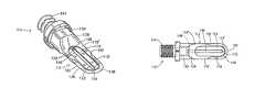
- FIG. 6is an isometric view of another ultrasonic surgical tool in accordance with the present invention.
- FIG. 7is a top plan view of the ultrasonic surgical tool of FIG. 6 .
- FIG. 8is a side elevational view of the ultrasonic surgical tool of FIGS. 6 and 7 .
- an ultrasonic surgical tool 10comprises a substantially planar blade body 12 having a pair of opposed major sides (not separately enumerated) provided with recessed surfaces 14 and 16 and a flange 18 extending around the recessed surfaces 14 and 16 on three sides thereof to define therewith a pair of opposing shallow recesses 20 and 22 .
- Flange 18extends away from recessed surfaces 14 and 16 , generally orthogonally or perpendicularly to the planes (not separately designated) of those surfaces.
- Flange 18serves as a rim or sidewall for each recess 20 and 22 .
- Recesses 20 and 22are delimited on a proximal side of blade body 12 by respective sidewalls 24 continuous with flange 18 and formed by a proximal blade body portion 26 that merges with a tapered portion 28 of a blade shank 30 .
- Blade body 12accordingly has a pair of opposed lateral surfaces 32 and 34 that are planar outer surfaces of proximal blade body portion 26 and flange 18 .
- Recessed surfaces 14 and 16are parallel to and inwardly spaced from lateral surfaces 32 and 34 .
- Recesses 20 and 22occupy nearly the entirety of blade body 12 along the opposite major sides thereof.
- Flange or rim 18is a narrow strip surrounding the recesses 20 and 22 .
- An outwardly facing surface 36 of flange 18includes a cutting edge or surface, at least at a distal tip 38 of blade body 12 and optionally along one or both lateral sides 40 and 42 of blade body 12 .
- Shank 30is integral on a distal side with blade body 12 and is provided at a proximal side with an externally threaded connector 44 for operatively linking the blade to a source (not shown) of ultrasonic mechanical vibrations.
- connector 44screws into a receptacle on a handpiece, the handpiece housing a piezoelectric crystal stack that generates ultrasonic vibrational energy in response to an electrical waveform input of an ultrasonic frequency.
- Blade body 12is provided with a through hole 46 extending between recessed surfaces 14 and 16 and providing a path of fluid communication between recesses 20 and 22 .
- Shank 28is provided with a bore or channel 48 having, in one embodiment of the ultrasonic surgical tool 10 , a single outlet port 50 communicating directly with one recess 20 .
- Bore or channel 48is connectable to a source of irrigant or cooling liquid and guides the liquid into recess 20 via outlet port 50 .
- the irrigant or cooling liquidenters the other recess 22 via through hole 46 .
- Outlet port 50is disposed at a proximal end of recess 20 , in sidewall 24 , and at a distance from through hole 46 .
- bore or channel 48may include a central axial upstream section 52 and a pair of branching downstream sections 54 and 56 terminating in respective outlet ports 58 and 60 .
- Outlet ports 58 and 60are located in proximal sidewalls 24 of recesses 20 and 22 . Recesses 20 and 22 therefore each receive irrigant or cooling liquid from bore or channel 48 via respective outlets 58 and 60 .
- Through hole 48may be eliminated but is preferably retained for pressure equalization and the resulting enhanced fluid flow.
- bore or channel 48may extend distally to an outlet opening 62 in sidewalls 24 of recesses 20 and 22 .
- Recessed surfaces 14 and 16define a web or septum (not separately designated) that bifurcates outlet opening 62 to form a pair of D-shaped output ports 64 and 66 .
- Recesses 20 and 22allow for improved irrigant delivery at a blade tissue interface, both along lateral surfaces 32 and 34 and cutting edge 38 , as well as along lateral surfaces 68 and 70 of flange or sidewall rim 18 . Lateral surfaces 68 and 70 may serve as additional cutting edges of blade body 12 .
- an ultrasonic surgical tool 110comprises a substantially planar blade body 112 having a pair of opposed major sides (not separately enumerated) provided with recessed surfaces 114 and 116 and a flange or shoulder 118 extending around the recessed surfaces 114 and 116 on three sides thereof to define therewith a pair of opposing shallow recesses (not separately designated).
- Flange 118is staggered away from recessed surfaces 114 and 116 , generally orthogonally or perpendicularly to the planes of those surfaces.
- Flange 118serves as a rim or sidewall that together with recessed surfaces 114 and 116 defined the recesses.
- the recessesare delimited on a proximal side of blade body 12 by respective sidewalls 124 continuous with flange 118 and formed by a tapered portion 128 of a blade shank 130 .
- Blade body 112accordingly has a pair of opposed lateral surfaces 132 and 134 ( FIG. 8 ) that are planar outer surfaces of flange 118 and that are continuous with respective sloped outer surfaces (not designated) of tapered shank portion 128 .
- Recessed surfaces 114 and 116are parallel to and inwardly spaced from lateral surfaces 132 and 134 .
- Recessed surfaces 114 and 116 and accordingly the associated recessesoccupy nearly the entirety of blade body 112 along the opposite major sides thereof, excepting a beveled cutting edge 126 that arcs about a distal tip 138 of blade body 112 and partially along a distal end of lateral sides 140 and 142 of blade body 112 .
- flange or rim 118is a narrow strip 118 ′ sandwiched between the recessed surfaces 114 and 116 and beveled cutting edge 126 .
- flange or rim 118is a broader strip 118 ′′ extending along the lateral sides 140 and 142 of blade body 112 .
- Shank 130is integral on a distal side with blade body 112 and is provided at a proximal side with an externally threaded connector 144 for operatively linking the blade to a source (not shown) of ultrasonic mechanical vibrations.
- connector 144screws into a receptacle on a handpiece, the handpiece housing a piezoelectric crystal stack that generates ultrasonic vibrational energy in response to an electrical waveform input of an ultrasonic frequency.
- Blade body 112is provided with an elongate through hole or slot 146 extending between recessed surfaces 114 and 116 and providing a path of fluid communication between the recesses on opposing major sides of blade body 112 .
- Shank 128is provided with a bore or channel 148 having a single outlet port 150 communicating directly with elongate through hole or slot 146 as well as the opposed recesses on the opposing major sides of blade body 112 .
- Through hole or slot 146extends in the proximal direction all the way to sidewalls 124 so that the through hole or slot is contiguous with the sidewalls 124 and is continuous with bore or channel 148 at outlet port 150 .
- Outlet port 150 outletextends in sidewalls 124 laterally away from through hole 146 on opposite sides thereof so that the outlet communicates with and overlaps both recesses 114 , 116 and through hole 146 .
- Bore or channel 148is connectable to a source of irrigant or cooling liquid and guides the liquid into through hole or slot 146 and the opposed shallow recesses via outlet port 150 .
- Recessed surfaces 114 and 116allow for improved irrigant delivery at a blade tissue interface, both along lateral surfaces 132 and 134 and cutting edge 126 .
- Blade body 112may be formed at a distal end of slot 146 with a beveled or sloped extension 152 facilitating irrigant movement from slot 146 towards the portion of cutting edge 126 at distal tip 138 , so that the irrigant is distributed along the distal tip.
- beveled cutting edge 126may be provided in the embodiment of FIGS. 1-3 and extend nearly along the entire sides 40 and 42 . Accordingly, it is to be understood that the drawings and descriptions herein are proffered by way of example to facilitate comprehension of the invention and should not be construed to limit the scope thereof.
Landscapes
- Health & Medical Sciences (AREA)
- Surgery (AREA)
- Life Sciences & Earth Sciences (AREA)
- Engineering & Computer Science (AREA)
- Heart & Thoracic Surgery (AREA)
- Animal Behavior & Ethology (AREA)
- Veterinary Medicine (AREA)
- Biomedical Technology (AREA)
- Dentistry (AREA)
- Medical Informatics (AREA)
- Molecular Biology (AREA)
- Nuclear Medicine, Radiotherapy & Molecular Imaging (AREA)
- General Health & Medical Sciences (AREA)
- Public Health (AREA)
- Mechanical Engineering (AREA)
- Oral & Maxillofacial Surgery (AREA)
- Surgical Instruments (AREA)
- Orthopedic Medicine & Surgery (AREA)
Abstract
Description
Claims (12)
Priority Applications (1)
| Application Number | Priority Date | Filing Date | Title |
|---|---|---|---|
| US15/204,788US9788852B2 (en) | 2013-06-28 | 2016-07-07 | Ultrasonic cutting blade with cooling liquid conduction |
Applications Claiming Priority (2)
| Application Number | Priority Date | Filing Date | Title |
|---|---|---|---|
| US13/931,003US9387005B2 (en) | 2013-06-28 | 2013-06-28 | Ultrasonic cutting blade with cooling liquid conduction |
| US15/204,788US9788852B2 (en) | 2013-06-28 | 2016-07-07 | Ultrasonic cutting blade with cooling liquid conduction |
Related Parent Applications (1)
| Application Number | Title | Priority Date | Filing Date |
|---|---|---|---|
| US13/931,003DivisionUS9387005B2 (en) | 2013-06-28 | 2013-06-28 | Ultrasonic cutting blade with cooling liquid conduction |
Publications (2)
| Publication Number | Publication Date |
|---|---|
| US20160338725A1 US20160338725A1 (en) | 2016-11-24 |
| US9788852B2true US9788852B2 (en) | 2017-10-17 |
Family
ID=52116309
Family Applications (2)
| Application Number | Title | Priority Date | Filing Date |
|---|---|---|---|
| US13/931,003Active2034-04-12US9387005B2 (en) | 2013-06-28 | 2013-06-28 | Ultrasonic cutting blade with cooling liquid conduction |
| US15/204,788ActiveUS9788852B2 (en) | 2013-06-28 | 2016-07-07 | Ultrasonic cutting blade with cooling liquid conduction |
Family Applications Before (1)
| Application Number | Title | Priority Date | Filing Date |
|---|---|---|---|
| US13/931,003Active2034-04-12US9387005B2 (en) | 2013-06-28 | 2013-06-28 | Ultrasonic cutting blade with cooling liquid conduction |
Country Status (7)
| Country | Link |
|---|---|
| US (2) | US9387005B2 (en) |
| EP (1) | EP3013260B1 (en) |
| JP (1) | JP6490065B2 (en) |
| CN (1) | CN105491968B (en) |
| CA (1) | CA2916914C (en) |
| ES (1) | ES2864717T3 (en) |
| WO (1) | WO2014210273A1 (en) |
Cited By (10)
| Publication number | Priority date | Publication date | Assignee | Title |
|---|---|---|---|---|
| US20170086872A1 (en)* | 2015-09-28 | 2017-03-30 | Olympus Corporation | Treatment method |
| US20170156737A1 (en)* | 2015-09-28 | 2017-06-08 | Olympus Corporation | Treatment method |
| US20170165507A1 (en)* | 2015-09-28 | 2017-06-15 | Olympus Corporation | Treatment method |
| US20180185054A1 (en)* | 2015-08-28 | 2018-07-05 | Olympus Corporation | Ultrasonic surgical system |
| US20180185053A1 (en)* | 2015-08-28 | 2018-07-05 | Olympus Corporation | Surgical system |
| US10682155B2 (en)* | 2016-03-31 | 2020-06-16 | Olympus Corporation | Ultrasonic treatment system for joint |
| US20220048214A1 (en)* | 2018-12-17 | 2022-02-17 | Ceratizit Como S.P.A. | Ultrasonic knife and ultrasonic cutting system |
| US11406414B2 (en) | 2018-10-23 | 2022-08-09 | Stryker European Operations Holdings Llc | Ultrasonic cutting tip for lumbar procedures |
| USD974558S1 (en) | 2020-12-18 | 2023-01-03 | Stryker European Operations Limited | Ultrasonic knife |
| US11980383B2 (en) | 2019-12-24 | 2024-05-14 | Farrow Medtech Llc | Wound-care apparatus and method for cleansing, desloughing, and debriding wounds |
Families Citing this family (20)
| Publication number | Priority date | Publication date | Assignee | Title |
|---|---|---|---|---|
| US9622767B2 (en) | 2013-09-11 | 2017-04-18 | Covidien Lp | Ultrasonic surgical instrument with cooling system |
| CN205234577U (en)* | 2015-11-23 | 2016-05-18 | 北京水木天蓬医疗技术有限公司 | Ultrasonic osteotome head and ultrasonic osteotome with same |
| US10456156B2 (en) | 2016-03-29 | 2019-10-29 | Covidien Lp | Devices, systems, and methods for cooling a surgical instrument |
| US10342566B2 (en) | 2016-03-29 | 2019-07-09 | Covidien Lp | Devices, systems, and methods for cooling a surgical instrument |
| US10405875B2 (en)* | 2016-05-05 | 2019-09-10 | Misonix, Incorporated | Ultrasonic surgical instrument and method for manufacturing same |
| US10702296B2 (en)* | 2016-05-25 | 2020-07-07 | Ethicon Llc | Ultrasonic surgical instrument with cooling conduit |
| US10463381B2 (en)* | 2016-07-27 | 2019-11-05 | Misonix, Inc. | Ultrasonic surgical probe, assembly, and related method |
| WO2018078825A1 (en)* | 2016-10-28 | 2018-05-03 | オリンパス株式会社 | Ultrasonic probe |
| US11134976B2 (en)* | 2018-01-08 | 2021-10-05 | Tao Song | Device having a multi-channel transmission member |
| USD888955S1 (en)* | 2018-01-31 | 2020-06-30 | Beijing Smtp Technology Co., Ltd. | Ultrasonic cutter head |
| US10881424B2 (en)* | 2018-02-13 | 2021-01-05 | Covidien Lp | Removable fluid reservoir and ultrasonic surgical instrument including the same |
| EP3856050B1 (en)* | 2018-09-24 | 2024-05-01 | Bosonic AG | Device for perforating a dense bone layer |
| CA3132081A1 (en) | 2019-03-08 | 2020-09-17 | Bosonic Ag | Device and method for treating tissue |
| US11844563B2 (en) | 2019-11-19 | 2023-12-19 | Covidien Lp | Energy-based surgical instruments incorporating cooling features |
| US11471168B2 (en)* | 2019-12-20 | 2022-10-18 | Innovations 4 Surgery, LLC | Medical devices and related methods for transforming bone, other tissue, or material |
| US12279787B2 (en) | 2020-02-27 | 2025-04-22 | Misonix, Llc | Spinal surgery method |
| US12414793B2 (en) | 2021-01-06 | 2025-09-16 | Covidien Lp | Devices, systems, and methods of manufacturing fluid-cooled ultrasonic surgical instruments |
| US12402905B2 (en) | 2021-08-13 | 2025-09-02 | Misonix, Llc | Serrated ultrasonic cutting blade with varied tooth pitch |
| US12402890B2 (en) | 2021-12-22 | 2025-09-02 | Innovations 4 Surgery, LLC | Medical cutting devices having a working blade body with static components and related methods of use |
| CN118217028B (en)* | 2024-02-28 | 2024-11-05 | 苏州市立医院 | A medical device kit for debridement and flushing |
Citations (20)
| Publication number | Priority date | Publication date | Assignee | Title |
|---|---|---|---|---|
| SU1424813A1 (en) | 1986-10-21 | 1988-09-23 | Саратовский государственный медицинский институт | Forceps for hemilorectomy |
| US4963153A (en) | 1987-06-30 | 1990-10-16 | Sulzer Brothers Limited | Metal tibial anchoring part for a partial knee joint prosthesis |
| US5167725A (en) | 1990-08-01 | 1992-12-01 | Ultracision, Inc. | Titanium alloy blade coupler coated with nickel-chrome for ultrasonic scalpel |
| US5205817A (en) | 1990-05-17 | 1993-04-27 | Sumitomo Bakelite Company Limited | Surgical instrument |
| US5261922A (en) | 1992-02-20 | 1993-11-16 | Hood Larry L | Improved ultrasonic knife |
| US5695510A (en)* | 1992-02-20 | 1997-12-09 | Hood; Larry L. | Ultrasonic knife |
| US6283981B1 (en) | 1998-06-29 | 2001-09-04 | Ethicon Endo-Surgery | Method of balancing asymmetric ultrasonic surgical blades |
| US6379371B1 (en)* | 1999-11-15 | 2002-04-30 | Misonix, Incorporated | Ultrasonic cutting blade with cooling |
| US20020077550A1 (en) | 1999-10-05 | 2002-06-20 | Rabiner Robert A. | Apparatus and method for treating gynecological diseases using an ultrasonic medical device operating in a transverse mode |
| US6443969B1 (en) | 2000-08-15 | 2002-09-03 | Misonix, Inc. | Ultrasonic cutting blade with cooling |
| US20030204199A1 (en) | 2002-04-30 | 2003-10-30 | Novak Theodore A. D. | Device and method for ultrasonic tissue excision with tissue selectivity |
| US20040030254A1 (en) | 2002-08-07 | 2004-02-12 | Eilaz Babaev | Device and method for ultrasound wound debridement |
| US20050177184A1 (en) | 2004-02-09 | 2005-08-11 | Easley James C. | Torsional dissection tip |
| US20070233131A1 (en) | 2006-02-28 | 2007-10-04 | Vermillion Technologies, Llc | Apparatus and method of creating an intervertebral cavity with a vibrating cutter |
| US20080058775A1 (en) | 2006-08-29 | 2008-03-06 | Darian Alexander L | Ultrasonic debrider probe and method of use |
| US20080183109A1 (en) | 2006-06-07 | 2008-07-31 | Bacoustics Llc | Method for debriding wounds |
| US20110105958A1 (en) | 2009-10-29 | 2011-05-05 | Bacoustics Llc | Ultrasound apparatus and methods for mitigation of neurological damage |
| US20110160624A1 (en) | 2007-07-13 | 2011-06-30 | Bacoustics, Llc | Apparatus for creating a therapeutic solution and debridement with ultrasound energy |
| USD680218S1 (en) | 2011-02-04 | 2013-04-16 | Misonix Incorporated | Ultrasonic bone cutting blade |
| US20150088179A1 (en) | 2013-09-26 | 2015-03-26 | Misonix Incorporated | Ultrasonic instrument and method using same |
Family Cites Families (4)
| Publication number | Priority date | Publication date | Assignee | Title |
|---|---|---|---|---|
| JPH0529697Y2 (en)* | 1988-12-07 | 1993-07-29 | ||
| US5318570A (en)* | 1989-01-31 | 1994-06-07 | Advanced Osseous Technologies, Inc. | Ultrasonic tool |
| US6887252B1 (en)* | 1996-06-21 | 2005-05-03 | Olympus Corporation | Ultrasonic treatment appliance |
| US8795367B2 (en)* | 2005-06-03 | 2014-08-05 | Arthrodisc, L.L.C. | Minimally invasive apparatus to manipulate and revitalize spinal column disc |
- 2013
- 2013-06-28USUS13/931,003patent/US9387005B2/enactiveActive
- 2014
- 2014-06-26CACA2916914Apatent/CA2916914C/enactiveActive
- 2014-06-26JPJP2016524182Apatent/JP6490065B2/enactiveActive
- 2014-06-26CNCN201480043643.2Apatent/CN105491968B/enactiveActive
- 2014-06-26ESES14817142Tpatent/ES2864717T3/enactiveActive
- 2014-06-26EPEP14817142.4Apatent/EP3013260B1/enactiveActive
- 2014-06-26WOPCT/US2014/044277patent/WO2014210273A1/enactiveApplication Filing
- 2016
- 2016-07-07USUS15/204,788patent/US9788852B2/enactiveActive
Patent Citations (21)
| Publication number | Priority date | Publication date | Assignee | Title |
|---|---|---|---|---|
| SU1424813A1 (en) | 1986-10-21 | 1988-09-23 | Саратовский государственный медицинский институт | Forceps for hemilorectomy |
| US4963153A (en) | 1987-06-30 | 1990-10-16 | Sulzer Brothers Limited | Metal tibial anchoring part for a partial knee joint prosthesis |
| US5205817A (en) | 1990-05-17 | 1993-04-27 | Sumitomo Bakelite Company Limited | Surgical instrument |
| US5167725A (en) | 1990-08-01 | 1992-12-01 | Ultracision, Inc. | Titanium alloy blade coupler coated with nickel-chrome for ultrasonic scalpel |
| US5261922A (en) | 1992-02-20 | 1993-11-16 | Hood Larry L | Improved ultrasonic knife |
| US5695510A (en)* | 1992-02-20 | 1997-12-09 | Hood; Larry L. | Ultrasonic knife |
| US6283981B1 (en) | 1998-06-29 | 2001-09-04 | Ethicon Endo-Surgery | Method of balancing asymmetric ultrasonic surgical blades |
| US20020077550A1 (en) | 1999-10-05 | 2002-06-20 | Rabiner Robert A. | Apparatus and method for treating gynecological diseases using an ultrasonic medical device operating in a transverse mode |
| US6379371B1 (en)* | 1999-11-15 | 2002-04-30 | Misonix, Incorporated | Ultrasonic cutting blade with cooling |
| US6443969B1 (en) | 2000-08-15 | 2002-09-03 | Misonix, Inc. | Ultrasonic cutting blade with cooling |
| US20030204199A1 (en) | 2002-04-30 | 2003-10-30 | Novak Theodore A. D. | Device and method for ultrasonic tissue excision with tissue selectivity |
| US8343178B2 (en) | 2002-04-30 | 2013-01-01 | Misonix, Incorporated | Method for ultrasonic tissue excision with tissue selectivity |
| US20040030254A1 (en) | 2002-08-07 | 2004-02-12 | Eilaz Babaev | Device and method for ultrasound wound debridement |
| US20050177184A1 (en) | 2004-02-09 | 2005-08-11 | Easley James C. | Torsional dissection tip |
| US20070233131A1 (en) | 2006-02-28 | 2007-10-04 | Vermillion Technologies, Llc | Apparatus and method of creating an intervertebral cavity with a vibrating cutter |
| US20080183109A1 (en) | 2006-06-07 | 2008-07-31 | Bacoustics Llc | Method for debriding wounds |
| US20080058775A1 (en) | 2006-08-29 | 2008-03-06 | Darian Alexander L | Ultrasonic debrider probe and method of use |
| US20110160624A1 (en) | 2007-07-13 | 2011-06-30 | Bacoustics, Llc | Apparatus for creating a therapeutic solution and debridement with ultrasound energy |
| US20110105958A1 (en) | 2009-10-29 | 2011-05-05 | Bacoustics Llc | Ultrasound apparatus and methods for mitigation of neurological damage |
| USD680218S1 (en) | 2011-02-04 | 2013-04-16 | Misonix Incorporated | Ultrasonic bone cutting blade |
| US20150088179A1 (en) | 2013-09-26 | 2015-03-26 | Misonix Incorporated | Ultrasonic instrument and method using same |
Cited By (18)
| Publication number | Priority date | Publication date | Assignee | Title |
|---|---|---|---|---|
| US10166042B2 (en)* | 2006-03-31 | 2019-01-01 | Olympus Corporation | Surgical system |
| US20180185053A1 (en)* | 2015-08-28 | 2018-07-05 | Olympus Corporation | Surgical system |
| US10687841B2 (en)* | 2015-08-28 | 2020-06-23 | Olympus Corporation | Ultrasonic surgical system |
| US20180185054A1 (en)* | 2015-08-28 | 2018-07-05 | Olympus Corporation | Ultrasonic surgical system |
| US10265549B2 (en)* | 2015-09-28 | 2019-04-23 | Olympus Corporation | Treatment method |
| US10194932B2 (en)* | 2015-09-28 | 2019-02-05 | Olympus Corporation | Treatment method |
| US10201366B2 (en)* | 2015-09-28 | 2019-02-12 | Olympus Corporation | Treatment method |
| US20170086872A1 (en)* | 2015-09-28 | 2017-03-30 | Olympus Corporation | Treatment method |
| US20170156737A1 (en)* | 2015-09-28 | 2017-06-08 | Olympus Corporation | Treatment method |
| US20170165507A1 (en)* | 2015-09-28 | 2017-06-15 | Olympus Corporation | Treatment method |
| US10682155B2 (en)* | 2016-03-31 | 2020-06-16 | Olympus Corporation | Ultrasonic treatment system for joint |
| US12310614B2 (en) | 2018-10-23 | 2025-05-27 | Stryker European Operations Holdings Llc | Ultrasonic cutting tip for lumbar procedures |
| US11406414B2 (en) | 2018-10-23 | 2022-08-09 | Stryker European Operations Holdings Llc | Ultrasonic cutting tip for lumbar procedures |
| US20220048214A1 (en)* | 2018-12-17 | 2022-02-17 | Ceratizit Como S.P.A. | Ultrasonic knife and ultrasonic cutting system |
| US11890769B2 (en)* | 2018-12-17 | 2024-02-06 | Ceratizit Como S.P.A. | Ultrasonic knife and ultrasonic cutting system |
| US11980383B2 (en) | 2019-12-24 | 2024-05-14 | Farrow Medtech Llc | Wound-care apparatus and method for cleansing, desloughing, and debriding wounds |
| USD1045078S1 (en) | 2020-12-18 | 2024-10-01 | Stryker European Operations Limited | Ultrasonic knife |
| USD974558S1 (en) | 2020-12-18 | 2023-01-03 | Stryker European Operations Limited | Ultrasonic knife |
Also Published As
| Publication number | Publication date |
|---|---|
| CN105491968A (en) | 2016-04-13 |
| EP3013260A4 (en) | 2017-03-01 |
| EP3013260B1 (en) | 2021-01-20 |
| EP3013260A1 (en) | 2016-05-04 |
| CA2916914C (en) | 2021-08-03 |
| CN105491968B (en) | 2019-07-30 |
| ES2864717T3 (en) | 2021-10-14 |
| CA2916914A1 (en) | 2014-12-31 |
| WO2014210273A1 (en) | 2014-12-31 |
| JP6490065B2 (en) | 2019-03-27 |
| US20160338725A1 (en) | 2016-11-24 |
| US20150005771A1 (en) | 2015-01-01 |
| JP2016526439A (en) | 2016-09-05 |
| HK1223532A1 (en) | 2017-08-04 |
| US9387005B2 (en) | 2016-07-12 |
Similar Documents
| Publication | Publication Date | Title |
|---|---|---|
| US9788852B2 (en) | Ultrasonic cutting blade with cooling liquid conduction | |
| EP3013259B1 (en) | Ultrasonic cutting blade with cooling liquid conduction | |
| US10219822B2 (en) | Ultrasonic cutting blade with cooling liquid conduction | |
| US9119658B2 (en) | Hook shaped ultrasonic cutting blade | |
| US6379371B1 (en) | Ultrasonic cutting blade with cooling | |
| EP1311197A4 (en) | ULTRASOUND SHARP BLADE WITH COOLING | |
| HK1223532B (en) | Ultrasonic cutting blade with cooling liquid conduction | |
| HK1223007B (en) | Ultrasonic cutting blade with cooling liquid conduction |
Legal Events
| Date | Code | Title | Description |
|---|---|---|---|
| AS | Assignment | Owner name:MISONIX, INCORPORATED, NEW YORK Free format text:ASSIGNMENT OF ASSIGNORS INTEREST;ASSIGNOR:VOIC, DAN;REEL/FRAME:039104/0402 Effective date:20130711 | |
| STCF | Information on status: patent grant | Free format text:PATENTED CASE | |
| AS | Assignment | Owner name:SILICON VALLEY BANK, MASSACHUSETTS Free format text:INTELLECTUAL PROPERTY SECURITY AGREEMENT;ASSIGNOR:MISONIX OPCO, INC.;REEL/FRAME:051447/0334 Effective date:20191226 | |
| AS | Assignment | Owner name:SWK FUNDING LLC, TEXAS Free format text:INTELLECTUAL PROPERTY SECURITY AGREEMENT;ASSIGNOR:MISONIX OPCO, INC.;REEL/FRAME:052167/0275 Effective date:20190927 | |
| MAFP | Maintenance fee payment | Free format text:PAYMENT OF MAINTENANCE FEE, 4TH YR, SMALL ENTITY (ORIGINAL EVENT CODE: M2551); ENTITY STATUS OF PATENT OWNER: SMALL ENTITY Year of fee payment:4 | |
| AS | Assignment | Owner name:WELLS FARGO BANK, NATIONAL ASSOCIATION, AS COLLATERAL AGENT, VIRGINIA Free format text:SECURITY INTEREST;ASSIGNOR:MISONIX OPCO, LLC;REEL/FRAME:058809/0950 Effective date:20211105 | |
| AS | Assignment | Owner name:MISONIX OPCO, INC., NEW YORK Free format text:RELEASE BY SECURED PARTY;ASSIGNOR:SWK FUNDING, LLC, AS COLLATERAL AGENT;REEL/FRAME:060220/0792 Effective date:20211029 Owner name:MISONIX OPCO, INC., NEW YORK Free format text:RELEASE BY SECURED PARTY;ASSIGNOR:SILICON VALLEY BANK;REEL/FRAME:060220/0773 Effective date:20211027 | |
| AS | Assignment | Owner name:MISONIX OPCO, LLC, NEW YORK Free format text:MERGER AND CHANGE OF NAME;ASSIGNORS:OYSTER OPCO MERGER SUB, LLC;MISONIX OPCO, INC.;REEL/FRAME:061433/0736 Effective date:20211103 | |
| FEPP | Fee payment procedure | Free format text:ENTITY STATUS SET TO UNDISCOUNTED (ORIGINAL EVENT CODE: BIG.); ENTITY STATUS OF PATENT OWNER: LARGE ENTITY | |
| AS | Assignment | Owner name:MISONIX, LLC, NEW YORK Free format text:MERGER AND CHANGE OF NAME;ASSIGNORS:MISONIX INCORPORATED;OYSTER MERGER SUB II, LLC;REEL/FRAME:061906/0564 Effective date:20211029 | |
| MAFP | Maintenance fee payment | Free format text:PAYMENT OF MAINTENANCE FEE, 8TH YEAR, LARGE ENTITY (ORIGINAL EVENT CODE: M1552); ENTITY STATUS OF PATENT OWNER: LARGE ENTITY Year of fee payment:8 | |
| AS | Assignment | Owner name:WELLS FARGO BANK, NATIONAL ASSOCIATION, AS ADMINISTRATIVE AGENT, TEXAS Free format text:SECURITY INTEREST;ASSIGNOR:MISONIX, LLC;REEL/FRAME:072298/0866 Effective date:20250731 | |
| AS | Assignment | Owner name:MISONIX OPCO, LLC, NEW YORK Free format text:RELEASE BY SECURED PARTY;ASSIGNOR:WELLS FARGO BANK, NATIONAL ASSOCIATION, AS COLLATERAL AGENT;REEL/FRAME:072338/0395 Effective date:20250731 |