US9787414B2 - Over-the air test - Google Patents
Over-the air testDownload PDFInfo
- Publication number
- US9787414B2 US9787414B2US13/259,505US201113259505AUS9787414B2US 9787414 B2US9787414 B2US 9787414B2US 201113259505 AUS201113259505 AUS 201113259505AUS 9787414 B2US9787414 B2US 9787414B2
- Authority
- US
- United States
- Prior art keywords
- over
- radio channel
- air
- antenna
- chamber
- Prior art date
- Legal status (The legal status is an assumption and is not a legal conclusion. Google has not performed a legal analysis and makes no representation as to the accuracy of the status listed.)
- Active
Links
Images


Classifications
- H—ELECTRICITY
- H04—ELECTRIC COMMUNICATION TECHNIQUE
- H04B—TRANSMISSION
- H04B15/00—Suppression or limitation of noise or interference
- G—PHYSICS
- G01—MEASURING; TESTING
- G01R—MEASURING ELECTRIC VARIABLES; MEASURING MAGNETIC VARIABLES
- G01R29/00—Arrangements for measuring or indicating electric quantities not covered by groups G01R19/00 - G01R27/00
- G01R29/08—Measuring electromagnetic field characteristics
- G01R29/0807—Measuring electromagnetic field characteristics characterised by the application
- G01R29/0814—Field measurements related to measuring influence on or from apparatus, components or humans, e.g. in ESD, EMI, EMC, EMP testing, measuring radiation leakage; detecting presence of micro- or radiowave emitters; dosimetry; testing shielding; measurements related to lightning
- G01R29/0821—Field measurements related to measuring influence on or from apparatus, components or humans, e.g. in ESD, EMI, EMC, EMP testing, measuring radiation leakage; detecting presence of micro- or radiowave emitters; dosimetry; testing shielding; measurements related to lightning rooms and test sites therefor, e.g. anechoic chambers, open field sites or TEM cells
- H—ELECTRICITY
- H01—ELECTRIC ELEMENTS
- H01Q—ANTENNAS, i.e. RADIO AERIALS
- H01Q3/00—Arrangements for changing or varying the orientation or the shape of the directional pattern of the waves radiated from an antenna or antenna system
- H01Q3/26—Arrangements for changing or varying the orientation or the shape of the directional pattern of the waves radiated from an antenna or antenna system varying the relative phase or relative amplitude of energisation between two or more active radiating elements; varying the distribution of energy across a radiating aperture
- H01Q3/267—Phased-array testing or checking devices
- H—ELECTRICITY
- H04—ELECTRIC COMMUNICATION TECHNIQUE
- H04B—TRANSMISSION
- H04B17/00—Monitoring; Testing
- H04B17/0082—Monitoring; Testing using service channels; using auxiliary channels
- H04B17/0085—Monitoring; Testing using service channels; using auxiliary channels using test signal generators
- H—ELECTRICITY
- H04—ELECTRIC COMMUNICATION TECHNIQUE
- H04B—TRANSMISSION
- H04B17/00—Monitoring; Testing
- H04B17/30—Monitoring; Testing of propagation channels
- H04B17/391—Modelling the propagation channel
- H—ELECTRICITY
- H04—ELECTRIC COMMUNICATION TECHNIQUE
- H04B—TRANSMISSION
- H04B17/00—Monitoring; Testing
- H04B17/30—Monitoring; Testing of propagation channels
- H04B17/391—Modelling the propagation channel
- H04B17/3912—Simulation models, e.g. distribution of spectral power density or received signal strength indicator [RSSI] for a given geographic region
- H—ELECTRICITY
- H04—ELECTRIC COMMUNICATION TECHNIQUE
- H04B—TRANSMISSION
- H04B17/00—Monitoring; Testing
- H04B17/20—Monitoring; Testing of receivers
- H04B17/21—Monitoring; Testing of receivers for calibration; for correcting measurements
- H—ELECTRICITY
- H04—ELECTRIC COMMUNICATION TECHNIQUE
- H04B—TRANSMISSION
- H04B17/00—Monitoring; Testing
- H04B17/30—Monitoring; Testing of propagation channels
- H04B17/391—Modelling the propagation channel
- H04B17/3911—Fading models or fading generators
Definitions
- the inventionrelates to over-the-air testing of a device in an anechoic chamber.
- a radio frequency signalWhen a radio frequency signal is transmitted from a transmitter to a receiver, the signal propagates in a radio channel along one or more paths having different angles of arrivals, signal delays, polarizations and powers. Also a frequency may change due to the Doppler effect. These changes may cause variation in signal strength and fadings of different durations. In addition, noise and interference due to other transmitters interfere with the radio connection.
- a transmitter and a receivercan be tested using a radio channel emulator emulating real circumstances.
- a radio channelis usually modelled with an FIR filter (Finite Impulse Response).
- OTAOver-The-Air
- a real DUTsuch a subscriber terminal
- the emulatormay be coupled to or act as a base station and emulate propagation paths between the subscriber terminal and the base station according to a channel model by generating independent Rayleigh faded signals, for example.
- OTA antennastransmit pre-processed communication signals to the DUT on the basis of weights determined by the emulated radio channel.
- the OTA chamberhas surfaces such as walls, cables and antenna stands which reflect the signals transmitted by the OTA antennas. Often the OTA antennas themselves cause echoes in the chamber. The unwanted reflections cause distortion to the emulated radio channel and deteriorate the quality of the emulation. On the other hand, it is technically very challenging to make the OTA chamber anechoic enough for the radio channel emulation, particularly with a moderate budget. Hence, there is need for a new approach to perform emulation in the OTA chamber.
- An aspect of the inventionrelates to an apparatus.
- a further aspect of the inventionrelates to an emulation system.
- a further aspect of the inventionrelates to a method.
- a further aspect of the inventionrelates to a method of performing radio channel emulation.
- a further aspect of the inventionrelates to a measurement arrangement.
- a further aspect of the inventionrelates to a simulation of a measurement arrangement.
- the inventionenables more accurate results in an OTA chamber.
- the inventionalso enables a use of an OTA chamber which has more echoes and thus more distortion than otherwise possible or desirable.
- FIG. 1shows a principle of calibration measurement plane geometrically
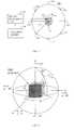
- FIG. 2presents a three dimensional configuration of the calibration measurement
- FIG. 3presents radio channel emulation in the OTA chamber
- FIG. 4shows an antenna with two polarization planes
- FIG. 5shows a structure of a FIR filter
- FIG. 6shows three dimensional radio channel emulation
- FIG. 7shows a flow chart of a method of calibration measurement
- FIG. 8a flow chart of a method of performing radio channel emulation.
- This applicationrelates to quantification and compensation of reflections, scattering and other non-idealities within an OTA chamber in a MIMO OTA test set-up.
- FIG. 1presents basic principles of calibration measurement in the OTA chamber two dimensionally.
- the OTA chamber 100should cause no effect to the emulated radio channel, the emulated radio channel is actually distorted by reflections, scattering and diffraction based on interactions between the transmission from the OTA antennas 102 to 116 and various structures in the OTA chamber 100 .
- a measuring arrangement for measuring the distortion caused by the OTA chamber 100comprises a signal processing unit 90 and at least one calibration antenna 92 (black dot).
- the signal processing unitmay be a part of the radio channel emulation system or a separate device. Often only one calibration antenna 92 is used.
- the calibration antenna 92is placed in at least two positions 94 (white dots and the position of the black dot) in a test zone 96 surrounded by over-the-air antennas 102 to 116 of an over-the-air chamber 100 at different moments of time.
- the test zone 96may be a quiet zone where the electric field provided by the OTA antennas 102 to 116 corresponds to the desired (theoretical) emulated radio channel and where a DUT (Device Under Test) is placed during the emulation. Hence, the similarity between the ideal radio channel and the realized radio channel in the quiet zone is high.
- the calibration antenna 92may be placed in several positions inside or at the border of the quiet zone.
- Calibration transmissionmay be transmitted from the OTA antennas 102 to 116 .
- An emulator or some other transmittermay feed the calibration transmission to the OTA antennas 102 to 116 .
- Calibration transmissioncomprises at least one predetermined signal.
- the signalmay be a frequency sweep signal, for example.
- the sweepmay be continuous or discrete.
- each calibration antenna 92receives calibration transmission from the over-the-air antennas 102 to 116 via interactions between the calibration transmission and structures associated with the over-the-air chamber 100 .
- the structuresmay comprise walls, cables, antenna stands and OTA antennas (which are not transmitting at that moment or at that code), for example.
- the interactionmay include reflection, scattering and diffraction, for example.
- a reflectionfor example, may be a first, second or a higher order reflection.
- the at least one calibration antenna 92may not be used to measure a line-of-sight transmission or the line-of-sight measurement may be ignored since it is not based on undesired interaction and hence it does not cause distortion during the radio channel emulation.
- the signal processing unit 90is coupled with the at least one calibration antenna 92 and the signal processing unit 90 receives signals from each calibration antenna 92 in response to the reception of the calibration transmission while each of the at least one calibration antenna 92 is in least two positions.
- the signal processing unit 90forms an OTA chamber model of the interactions on the basis of the received signals.
- the OTA chamber modelis constant with respect to time.
- the signal processing unit 90also stores the OTA chamber model in an OTA chamber model memory 98 .
- the OTA chamber model memory 98may be a part of the signal processing unit 90 or some other device.
- the OTA chamber modelmay be copied or moved to a memory of another device, too.
- the OTA channel modelmay be utilized when a radio frequency transmission from the over-the-air antennas 102 to 116 is predistorted in the over-the-air chamber 100 in order to cancel effects of the undesired interactions at least partly.
- FIG. 2presents a three dimensional configuration of the calibration measurement.
- K OTA antennas 102 to 116 in solid angle directions ⁇ k( ⁇ k , ⁇ k ) as shown in FIG. 2 .
- Each solid angle directionmay be expressed with two plane angles ⁇ , ⁇ , which may be orthogonal. If a plane geometrical measurement is performed, one of the angles ⁇ , ⁇ is just omitted.
- the first direction ( ⁇ 1 , ⁇ 1 )may be chosen as the origin and the rest of the directions may be measured with respect to the first one.
- the calibration antenna 92may be dual polarized such that its polarization isolation between orthogonal polarization directions is high, for example 20 dB or more.
- the calibration antenna 92may be some kind of horn antenna with orthogonal polarizations.
- Each OTA antenna 102 to 116may transmit a calibration transmission separately.
- the transmissions of different OTA antennas 102 to 116may be separated by time division and/or code division both in transmission and reception.
- time divisioneach OTA antenna 102 to 116 transmits at different moment.
- code divisioneach OTA antenna 102 to 116 transmits using a unique code the signals received may be distinguished by decoding the signals at reception.
- several or all OTA antennasmay transmit at the same time.
- a next OTA antenna 102 to 116may start transmission, for example.
- all OTA antennas 102 to 116may transmit a calibration signal while the calibration antenna 92 is in one position.
- the calibration antenna 92may be moved to another position and the measurement may be repeated.
- received complex amplitudesare measured.
- the measured frequenciesmay form a band (of discrete frequencies) or they may be pseudo-random or deterministic frequencies substantially separate from each other.
- the measurementis performed for each of the K OTA antennas' transmission separately.
- the calibration measurementgives a complex field matrix E cal (k, ⁇ , r ) ⁇ C K ⁇ N ⁇ M for K OTA antennas with N directions and M locations, i.e. C K ⁇ N ⁇ M refers to complex values of K ⁇ N ⁇ M dimensions.
- the calibration measurementmay give a complex field matrix for V frequencies and 2 polarizations (E ⁇ and E ⁇ ). Then the complete electric field matrix becomes E cal (k, ⁇ , ⁇ , f, r ) ⁇ C K ⁇ 2 ⁇ N ⁇ V ⁇ M for K OTA antennas.
- the signal processing unit 90may process the signals associated with the calibration transmission as a function of an over-the-air antenna and a direction. A time dependent variation does not need to be taken into account usually. Additionally or alternatively, the signal processing unit 90 may process the signals associated with the calibration transmission as a function of a frequency and a polarization.
- the calibration measurementmay be separable with respect to time, OTA antenna, direction, frequency and polarization.
- This matrix processingmay be performed in the signal processing unit 90 .
- the actual measurementmay be performed using a vector network analyzator, for example.
- the signal processingmay be performed using a suitable personal computer with a suitable computer program.
- the maximum number of separate directions Nis limited by the beam width of the calibration antenna 92 , i.e. the result of 4 ⁇ st divided by the opening solid angle of the calibration antenna 92 . It is not feasible to measure more than one sample within the beam width.
- the purpose of the calibration measurementis to get spatial frequency responses which are based on reflections and other imperfections within the OTA chamber 100 . Additionally or alternatively, the purpose of the calibration measurement is to get polarimetric frequency responses which are based on reflections and other imperfections within the OTA chamber 100 .
- the complex field E cal (k, ⁇ , ⁇ , f, r )doesn't need to contain the transmission in a direct path from OTA antenna k to the calibration antenna 92 .
- the calibration measurementcan be interpreted as follows.
- the electric field E cal in polarization ⁇ , direction ⁇ , frequency f and location ris E cal (k, ⁇ , f, r ).
- the electric field matrix E cal (k, ⁇ , ⁇ , f, r ) ⁇ C K ⁇ 2 ⁇ N ⁇ V ⁇ Mwhich is an OTA chamber model and which is formed on the basis of calibration measurement is stored for to be used in radio channel emulation.
- the calibration measurementmay be done only once. Particularly this is true if the physical set-up in the OTA chamber is kept unchanged. In any case, the environment should be deterministic and time invariant for the calibration measurement to be successful.
- FIG. 3presents emulation in the OTA chamber.
- FIG. 3is two dimensional for clarity and simplicity.
- a DUT 300which is an electrical device, is in the centre and over-the-air (OTA) antennas 102 , 104 , 106 , 108 , 110 , 112 , 114 and 116 may be around the DUT 300 .
- the DUT 300may be a computer or a subscriber terminal, for example. They may have a uniform spacing (e.g. 45° between each of the 8 elements).
- the DUT 300in turn, may be in a test zone 96 .
- each of the antenna elementsmay be connected to a single emulator output port of an emulator 118 such as EB (Elektrobit) Propsim® F8 and hence each antenna element may receive a signal through one signal path from the emulator 118 .
- EBElektrobit
- the emulator 118may comprise FIR filters for weighting and delaying each signal path 130 from the transmitter 122 to the antenna 102 to 116 . Additionally or alternatively, the emulator 118 may comprise a processor, a memory and a suitable computer program for providing the OTA antennas 102 to 116 with the antenna channels.
- the distance between the DUT 300 and the antenna elements 102 to 116may be the same or the OTA antennas 102 to 116 may also be at different distances from the DUT 300 .
- the antenna elements 102 to 116may only be placed in a sector instead of being placed at a full angle or a full solid angle.
- the OTA antennas 102 to 116may also be movable. In any case, the positions of the OTA antennas 102 to 116 are predetermined at each moment with respect to the test zone 96 and their positions ought to correspond to positions of the calibration measurement.
- the emulator 118may be coupled to a transmitter 122 using an output connector of the transmitter 122 .
- the transmitter 122may be a base station of a radio system or the like.
- the DUT 300may act as a receiving subscriber terminal of the radio system or the like. Antenna characteristics of the DUT 300 may be ignored.
- a radio channel generator 120may have a plurality of radio channel models in its memory or a radio channel may be formed in real time by hard ware, for example.
- a radio channel modelmay be a play back model based on a channel recorded from a real radio system or it may be an artificially generated model or it may be a combination of a playback model and an artificially generated model.
- the radio channel generator 120defines the environment in which the DUT 300 should receive communication signals from the transmitter 122 .
- the radio channel generator 120also has information on the configuration of the OTA antennas 102 to 116 with respect to the DUT 300 (distance from DUT, angle with respect to DUT and polarization of signals, for example).
- the radio channel generator 120provides a weight for each signal path 130 from the emulator 118 to an antenna 102 to 116 on the basis of the predefined information with respect to the OTA antennas 102 to 116 , a form of transmission from the OTA antennas 102 to 116 , the desired electric field in the test zone 96 , for example. If the weights are fed to the emulator 118 without taking into account the calibration measurement, they form a desired radio channel between the transmitter 122 and the DUT 300 with distortions.
- the radio channel generator 120has a radio channel model which is predistorted by the invert model formed during the calibration measurement. That is why the weights fed to the emulator 118 form a desired radio channel between the transmitter 122 and the DUT 300 without distortions or with less distortions.
- the used radio channel modelis known. From the radio channel model realizations it is possible to derive an instantaneous target field E t ( ⁇ , ⁇ , f, r , t) at a time instant t. Since the instantaneous target field E t ( ⁇ , ⁇ , f, r , t) is derivable, its approximate or exact form may be derived in several manners (see Equation (2)).
- an electric field generation of each path from an antenna of the transmitter 122 to an OTA antenna 102 to 116has a time variant impulse response.
- the impulse responsedepends on both the used radio channel model which is also predetermined and an OTA antenna position in the OTA chamber.
- an over-the-air antenna-specific element in the impulse response matrixcontributes in a known manner to the electric field in the over-the-air chamber 100 and vice versa.
- the impulse responsecan be (Fourier) transformed to a frequency response H orig (k, f, t).
- H origk, f, t
- the signal transmitted from an OTA antenna khas a frequency response H orig (k, f, t) (in the radio channel emulator).
- a distortion electric field matrix E distmay be formed on the basis of the frequency response H orig (k, f, t) and the electric field matrix E cal (k, ⁇ , ⁇ , f, r ) generated by a transmission of an emulated radio channel.
- the antenna-specific distortion electric field E distmay be formed as a convolution of the frequency response H orig (k, f, t) and the measured chamber model E cal (k, ⁇ , ⁇ , f, r ).
- the convolutionmay be expressed as a product of matrices E cal and elements of H orig in a frequency dimension.
- iis the k th OTA antenna's i th frequency response value.
- ⁇ kis a vector from OTA antenna k to the origin
- cis the speed of light
- f cis the carrier centre frequency
- PL(u,f)is the free space loss as a function of distance u (meters) and frequency f.
- the measurement which is explained abovemay be simulated using a computer and a proper simulation program instead of really performing the measurement.
- the simulationrequires parameters of the OTA chamber 100 such as its physical dimensions, for example. Additionally, information on OTA antennas 102 to 116 , test zone 96 and the at least one calibration antenna 92 is needed.
- Various structures in and of the OTA chamber 100may be simulated if their properties and positions are known i.e. have a measured value. Then a virtual OTA chamber may be created and a virtual measurement performed.
- a simulation of a measurementmay be performed using at least one processor and a memory including a computer program code, the at least one memory and the computer program code may, with the at least one processor, cause the simulation to provide at least one virtual calibration antenna placable in at least two virtual positions in a virtual test zone in a virtual over-the-air chamber including virtual over-the-air antennas which then may virtually transmit calibration transmission.
- At least one virtual calibration antenna at each virtual positionmay virtually receive the virtual calibration transmission of the virtual over-the-air antennas via virtual interactions between the virtual calibration transmission and virtual structures associated with the virtual over-the-air chamber.
- a channel model based on the virtually received signalsmay be formed and the chamber model may be stored in a memory for cancellation of effects of the undesired interactions by a predistortion of a radio frequency transmission from the over-the-air antennas in the over-the-air chamber.
- the antipodal fieldmay be created by the OTA antennas 102 to 116 .
- the corresponding frequency responses H anti (k, f, t) for K OTA antennasmay be determined.
- the antipodal fieldmay be formed in a similar manner to the derivation of the instantaneous target field E t ( ⁇ , ⁇ , f, r, t) explained earlier.
- the antipodal fieldmay be based on plane waves, for example.
- a weight for each signal path associated with an antenna of a plurality of OTA antennas 102 to 116 around a test zone 92 in an over-the-air chamber 100may be formed by a comparison of a desired target electric field based on a radio channel model and an electric field obtainable by the plane waves associated with the test zone 92 , the plane waves being transmittable by the OTA antennas 102 to 116 .
- the target fieldhere is zero.
- the use of the plane waves for creating a desired fieldis known per se, and it is explained in more detail in the patent application PCT/FI2011/050190.
- Grefers to H anti which is to be solved and which is the only unknown in the equation
- Trefers to E anti which is based on measurements. Since the antipodal field is derivable, its approximate or exact form may be derived in several manners.
- the addition operation (+)represents the pre-distortion by which the invert model H anti pre-distorts the radio channel H orig .
- a radio channel model H orig (k, f, t)is pre-distorted by the chamber model the inverted model of which is represented by the frequency response H anti (k, f, t).
- the invert modelmay be iterated in the signal processing unit 90 by forming and storing a next invert model in response to a calibration transmission predistorted by the present invert model.
- iterative processing is not necessarily required.
- FIG. 4presents an antenna having antenna elements 402 , 404 for two orthogonal polarizations.
- Orthogonal polarization components 406 , 408e.g. vertical V and horizontal H
- invert modelit may be possible to use a lower quality chamber which is technically less challenging and more economical. It may be possible to use a normal room as a facility for MIMO OTA radio channel testing.
- FIG. 5shows a block diagram of a FIR filter which may comprise delay elements 500 to 504 arranged as a shift register, multipliers 506 and a summer 508 .
- the basic function of an FIR filtermay be described as follows.
- the signal componentsare summed together in a summer 508 .
- the delay dispersionmay be controlled by weighting different delays of the input signals
- the output signal y(nn) of a FIR filtermay be expressed as a convolution of the sum of the product of the delayed signal and the weights h(k):
- Signals x and y and a weight hmay be processed in a scalar form, vector form or matrix form. Generally, weights h may be real or complex.
- FIG. 6presents a solid geometrical embodiment of an OTA test chamber.
- the antenna elements(rectangles) are placed (as if) on a surface of a sphere while the DUT 300 is in the middle of the sphere.
- the surface on which the antenna elements are (as if) placedmay be a part of any surface which encloses a volume. Examples of such surfaces are a surface of a cube, an ellipsoid, a tetrahedra, etc.
- FIG. 7presents a flow chart of the method of forming an invert model of the OTA chamber.
- at least one calibration antennais placed in at least two positions in a test zone in an over-the-air chamber including over-the-air antennas.
- calibration transmission of the over-the-air antennas via interactions between the calibration transmission and structures associated with the over-the-air chamber at each positionis received by the at least one calibration antenna.
- a chamber model with the interactions on the basis of the received signalsis formed by a signal processing, and the chamber model is stored in a memory for a cancellation of effects of the undesired interactions by a predistortion of a radio frequency transmission from the over-the-air antennas in the over-the-air chamber.
- FIG. 8presents a flow chart of the method of performing a radio channel emulation with an invert model of the OTA chamber.
- a communication signalis weighted in an emulator with the radio channel model distorted by a predetermined chamber model formed in the method described FIG. 7 .
- the weighted communication signalis fed to over-the-air antennas for transmission to a device under test.
- An embodimentprovides a computer program embodied on a distribution medium, comprising program instructions which, when loaded into an electronic apparatus, execute the method described above in connection with FIGS. 7 and 8 .
- the computer programmay be in source code form, object code form, or in some intermediate form, and it may be stored in some sort of carrier, which may be any entity or device capable of carrying the program.
- carrierinclude a record medium, computer memory, read-only memory, and software distribution package, for example.
- the computer programmay be executed in a single electronic digital computer or it may be distributed amongst a number of computers.
Landscapes
- Physics & Mathematics (AREA)
- Electromagnetism (AREA)
- Engineering & Computer Science (AREA)
- Computer Networks & Wireless Communication (AREA)
- Signal Processing (AREA)
- Spectroscopy & Molecular Physics (AREA)
- General Physics & Mathematics (AREA)
- Monitoring And Testing Of Transmission In General (AREA)
- Variable-Direction Aerials And Aerial Arrays (AREA)
- Radio Transmission System (AREA)
Abstract
Description
Edist(ki,Ψ,Ω,fv,
where Hk
where Ēφ,kis the gain vector of kthOTA antenna with Eφpolarization, “E”
is a phase term,
“E”↓“dist”t“tot”(“(”,“(”,“f”↓“(”“,”(“r,”)

with or without ∥Ēφ,k∥, G refers to Hantiwhich is to be solved and which is the only unknown in the equation, and T refers to Eantiwhich is based on measurements. Since the antipodal field is derivable, its approximate or exact form may be derived in several manners.
H(k,f,t)=Horig(k,f,t)+Hanti(k,f,t). (4)
where * denotes a convolution operation and n denotes the index of a signal element. Signals x and y and a weight h may be processed in a scalar form, vector form or matrix form. Generally, weights h may be real or complex.
Claims (23)
Applications Claiming Priority (1)
| Application Number | Priority Date | Filing Date | Title |
|---|---|---|---|
| PCT/FI2011/050637WO2013004887A1 (en) | 2011-07-06 | 2011-07-06 | Over-the-air test |
Publications (2)
| Publication Number | Publication Date |
|---|---|
| US20140122049A1 US20140122049A1 (en) | 2014-05-01 |
| US9787414B2true US9787414B2 (en) | 2017-10-10 |
Family
ID=47436578
Family Applications (1)
| Application Number | Title | Priority Date | Filing Date |
|---|---|---|---|
| US13/259,505ActiveUS9787414B2 (en) | 2011-07-06 | 2011-07-06 | Over-the air test |
Country Status (6)
| Country | Link |
|---|---|
| US (1) | US9787414B2 (en) |
| EP (1) | EP2730040B1 (en) |
| JP (1) | JP2014518385A (en) |
| KR (1) | KR101878530B1 (en) |
| CN (1) | CN103650389B (en) |
| WO (1) | WO2013004887A1 (en) |
Families Citing this family (21)
| Publication number | Priority date | Publication date | Assignee | Title |
|---|---|---|---|---|
| US9698920B2 (en)* | 2012-02-13 | 2017-07-04 | Keysight Technologies Singapore (Holdings) Pte. Ltd. | Radio channel data and the use thereof |
| US9337941B2 (en) | 2014-06-20 | 2016-05-10 | The United States Of America As Represented By The Secretary Of The Navy | Antenna systems and methods for over-the-air transmitter signal measurement |
| CN105991197A (en)* | 2015-02-05 | 2016-10-05 | 联想(北京)有限公司 | Wireless signal testing device, testing system and testing method |
| US10003417B2 (en)* | 2016-03-22 | 2018-06-19 | Octoscope Inc. | Controllable multi-user MIMO testbed |
| JP6732228B2 (en) | 2016-03-31 | 2020-07-29 | 華為技術有限公司Huawei Technologies Co.,Ltd. | Signal transmission method for terminal device and terminal device |
| CN107543978B (en)* | 2016-06-23 | 2021-08-24 | 是德科技股份有限公司 | System and method for calibrating radiation channel matrix in MIMO via OTA radiation test system |
| EP3399674B1 (en) | 2017-05-04 | 2022-03-02 | Rohde & Schwarz GmbH & Co. KG | Radio test system and method for testing a device under test |
| US11579179B2 (en)* | 2018-09-11 | 2023-02-14 | Jabil Inc. | Method for providing an antenna probe array for a compact anechoic chamber for active and passive antenna over-the-air testing |
| US12130380B2 (en) | 2018-09-11 | 2024-10-29 | Jabil Inc. | Over-the-air product verification test using antenna and reflector arrays |
| US10725146B2 (en)* | 2018-09-27 | 2020-07-28 | Humatics Corporation | Wideband radio-frequency antenna |
| US20200106538A1 (en)* | 2018-09-27 | 2020-04-02 | Humatics Corporation | Angular impulse delay in radio-frequency antennas |
| CN109743744B (en)* | 2018-12-19 | 2022-03-08 | 深圳创维数字技术有限公司 | Wireless performance test method, device, equipment and readable storage medium |
| US10944491B2 (en)* | 2019-01-03 | 2021-03-09 | Rohde & Schwarz Gmbh & Co. Kg | Method and system for positioning a device under test within a test area |
| EP3748374B8 (en)* | 2019-06-06 | 2023-02-15 | Rohde & Schwarz GmbH & Co. KG | System and method for calibrating radio frequency test chambers |
| EP3748375B1 (en)* | 2019-06-07 | 2023-05-24 | Rohde & Schwarz GmbH & Co. KG | System and method of characterizing a quiet zone of an over-the-air testing space |
| US20210036820A1 (en)* | 2019-08-01 | 2021-02-04 | Qualcomm Incorporated | Test chamber parasitic channel equalization |
| JP7012914B1 (en)* | 2020-03-23 | 2022-01-28 | 三菱電機株式会社 | Array antenna calibration device and calibration method |
| KR20230004586A (en)* | 2020-04-09 | 2023-01-06 | 프라운호퍼 게젤샤프트 쭈르 푀르데룽 데어 안겐반텐 포르슝 에. 베. | Beam correspondence parameter determination |
| CN112630549A (en)* | 2020-12-10 | 2021-04-09 | 深圳市新益技术有限公司 | Polygonal spherical space sampling equipment |
| CN113671270B (en)* | 2021-07-21 | 2024-06-11 | 西安空间无线电技术研究所 | Antenna test system and method based on digital switch |
| US11709191B1 (en) | 2022-04-29 | 2023-07-25 | Rohde & Schwarz Gmbh & Co. Kg | Compact antenna test range system and method for calibrating a compact antenna test range |
Citations (11)
| Publication number | Priority date | Publication date | Assignee | Title |
|---|---|---|---|---|
| WO1993020626A1 (en) | 1992-04-01 | 1993-10-14 | Elektrobit Oy | RADIO CHANNEL FADING SIMULATOR AND FADING SIMULATION METHOD |
| US5862455A (en) | 1993-06-07 | 1999-01-19 | Martin Communications Pty Ltd | Fading simulator |
| WO2003041308A1 (en) | 2001-11-09 | 2003-05-15 | Elektrobit Oy | Method and device for simulating a radio channel |
| US20080056340A1 (en)* | 2006-07-24 | 2008-03-06 | Michael Foegelle | Systems and methods for over the air performance testing of wireless devices with multiple antennas |
| CN101605350A (en) | 2009-07-01 | 2009-12-16 | 工业和信息化部通信计量中心 | Based on multiple wireless access technology space Performance Test System and method of testing thereof |
| WO2010040887A1 (en)* | 2008-10-06 | 2010-04-15 | Elektrobit System Test Oy | Over-the-air test |
| CN101997618A (en) | 2009-08-21 | 2011-03-30 | 中兴通讯股份有限公司 | Related device and method in test of MIMO wireless terminal |
| CN101998455A (en) | 2009-08-21 | 2011-03-30 | 中兴通讯股份有限公司 | Test method and test system for spatial radio-frequency performance of multi-antenna system |
| WO2011051537A1 (en) | 2009-10-26 | 2011-05-05 | Elektrobit System Test Oy | Over-the-air test |
| US20110134001A1 (en) | 2009-05-11 | 2011-06-09 | Tsutomu Sakata | Antenna evaluation apparatus for evaluating multiple wave of radio waves transmitted from scatterer antennas with function of calibration for the same apparatus |
| WO2012117147A1 (en) | 2011-03-02 | 2012-09-07 | Elektrobit System Test Oy | Over-the-air test |
Family Cites Families (9)
| Publication number | Priority date | Publication date | Assignee | Title |
|---|---|---|---|---|
| JP3691590B2 (en)* | 1996-07-02 | 2005-09-07 | 横河電機株式会社 | Shield box |
| JP2000151499A (en)* | 1998-11-12 | 2000-05-30 | Mitsubishi Electric Corp | Wireless communication terminal evaluation device |
| JP4091190B2 (en)* | 1998-12-18 | 2008-05-28 | 三菱電機株式会社 | Radio environment parameter determination method for wireless terminal test, wireless terminal test apparatus |
| KR100397345B1 (en)* | 2001-09-10 | 2003-09-13 | 케이엠텔레콤 주식회사 | Interference cancelliiation system simulator for test and performance evaluation of broadband wireless repeater and simulation method thereof |
| US8050649B2 (en)* | 2005-08-30 | 2011-11-01 | Qualcomm Incorporated | Downconversion mixer with IM2 cancellation |
| KR101402249B1 (en)* | 2008-02-18 | 2014-06-30 | 삼성전자주식회사 | Apparatus and method for burst allocation in a broadband wireless communication system |
| JP2010054302A (en)* | 2008-08-27 | 2010-03-11 | Murata Mfg Co Ltd | Method of estimating anechoic characteristic |
| US8880002B2 (en)* | 2009-06-03 | 2014-11-04 | Elektrobit System Test Oy | Over-the-air test |
| JP5448158B2 (en)* | 2009-11-10 | 2014-03-19 | 独立行政法人情報通信研究機構 | Antenna measurement method, antenna calibration method |
- 2011
- 2011-07-06USUS13/259,505patent/US9787414B2/enactiveActive
- 2011-07-06WOPCT/FI2011/050637patent/WO2013004887A1/enactiveApplication Filing
- 2011-07-06EPEP11869166.6Apatent/EP2730040B1/enactiveActive
- 2011-07-06JPJP2014517853Apatent/JP2014518385A/enactivePending
- 2011-07-06CNCN201180072091.4Apatent/CN103650389B/enactiveActive
- 2011-07-06KRKR1020147000072Apatent/KR101878530B1/enactiveActive
Patent Citations (11)
| Publication number | Priority date | Publication date | Assignee | Title |
|---|---|---|---|---|
| WO1993020626A1 (en) | 1992-04-01 | 1993-10-14 | Elektrobit Oy | RADIO CHANNEL FADING SIMULATOR AND FADING SIMULATION METHOD |
| US5862455A (en) | 1993-06-07 | 1999-01-19 | Martin Communications Pty Ltd | Fading simulator |
| WO2003041308A1 (en) | 2001-11-09 | 2003-05-15 | Elektrobit Oy | Method and device for simulating a radio channel |
| US20080056340A1 (en)* | 2006-07-24 | 2008-03-06 | Michael Foegelle | Systems and methods for over the air performance testing of wireless devices with multiple antennas |
| WO2010040887A1 (en)* | 2008-10-06 | 2010-04-15 | Elektrobit System Test Oy | Over-the-air test |
| US20110134001A1 (en) | 2009-05-11 | 2011-06-09 | Tsutomu Sakata | Antenna evaluation apparatus for evaluating multiple wave of radio waves transmitted from scatterer antennas with function of calibration for the same apparatus |
| CN101605350A (en) | 2009-07-01 | 2009-12-16 | 工业和信息化部通信计量中心 | Based on multiple wireless access technology space Performance Test System and method of testing thereof |
| CN101997618A (en) | 2009-08-21 | 2011-03-30 | 中兴通讯股份有限公司 | Related device and method in test of MIMO wireless terminal |
| CN101998455A (en) | 2009-08-21 | 2011-03-30 | 中兴通讯股份有限公司 | Test method and test system for spatial radio-frequency performance of multi-antenna system |
| WO2011051537A1 (en) | 2009-10-26 | 2011-05-05 | Elektrobit System Test Oy | Over-the-air test |
| WO2012117147A1 (en) | 2011-03-02 | 2012-09-07 | Elektrobit System Test Oy | Over-the-air test |
Non-Patent Citations (39)
| Title |
|---|
| Anon: Discover StarMIMO: The clear answer to MIMO testing (product brochure); one page; May 8, 2010.* |
| Dashti et al.; "Antenna radiation pattern influence on UWB ranging accuracy," Antennas and Propagation (EuCAP), 2010 Proceedings of the Fourth European Conference on , vol., No., pp. 1-5, Apr. 2010.* |
| Elektrobit et al: "TP: Test Plan for Anechoic Chamber Based MIMO OTA Methods," 3GPP Draft; R4-102241, 3rd Generation Partnership Project (3GPP), Mobile Competence Centre; 650, Route Des Lucioles; F-06921 Sophia-Antipolis Cedex France, vol. RAN WG4, No. Montreal, Canada; May 26, 2010, XP050427246, [retrieved on May 26, 2010 * paragraph [06.2]-paragraph [82.11]. |
| ELEKTROBIT, NOKIA, ETS-LINDGREN, SATIMO, SPIRENT COMMUNICATIONS, AGILENT TECHNOLOGIES, ROHDE&SCHWARZ, NTT DOCOMO, LG ELECTRONICS: "TP: Test Plan for Anechoic Chamber based MIMO OTA methods", 3GPP DRAFT; R4-102241, 3RD GENERATION PARTNERSHIP PROJECT (3GPP), MOBILE COMPETENCE CENTRE ; 650, ROUTE DES LUCIOLES ; F-06921 SOPHIA-ANTIPOLIS CEDEX ; FRANCE, vol. RAN WG4, no. Montreal, Canada; 20100510, R4-102241, 26 May 2010 (2010-05-26), Mobile Competence Centre ; 650, route des Lucioles ; F-06921 Sophia-Antipolis Cedex ; France, XP050427246 |
| Feng et al. "Simulation based comparison of metrics and measurement methodologies for OTA test of MIMO terminals," Antennas and Propagation (EuCAP), 2010 Proceedings of the Fourth European Conference on , vol., No., pp. 1,5, Apr. 12-16, 2010.* |
| First China Office Action dated Jan. 6, 2015, regarding China Application 201180072091.4, 6 pp. |
| Gan et al., "The FPGA Implementation of Short-Wave Channel Model", Chinese Journal of Electronics, vol. 12. No. 1. Jan. 2003, pp. 25-28. |
| Hallbjorner et al., "Measurement Uncertainty in Multipath Simulators Due to Scattering within the Antenna Array-Theoretical Model Based on Mutual Coupling", IEEE Antennas and Wireless Propagation Letters, vol. 9, pp. 1103-1106(2010). |
| Hanley: Press Release; EB and SATIMO Unite Their Expertise in MIMO OTA Testing; May 2010; pp. 1-2.* |
| Heino (ed): D5.3: WINNER+ Final Channel Models; Project No. CELTIC / CP5-026; Project title: Wireless World Initiative New Radio—WINNER;Jun. 30, 2010; 107 pages.* |
| Heino, "D5.3: Winner+Final Channel Models", Wireless World Initiative New Radio-Winner, Jun. 30, 2010, pp. 80-93. |
| International Preliminary Report on Patentability dated Jan. 7, 2014 for International Application No. PCT/FI2011/050637, 8 pages. |
| International Preliminary Report on Patentability dated Oct. 10, 2005 for Application No. PCT/FI2003/000929, 5 pages. |
| International Search Report dated Apr. 5, 2012 for International Application No. PCT/FI2011/050637, 6 pages. |
| Jamsa et al., "Real-Time Simulation of Adaptive Array Antenna using Broadband Vector Channel Simulator", IEEE, 2002, pp. 188-192. |
| Kolu et al., "A real-time simulator for MIMO radio channels", IEEE, 2002, pp. 568-572. |
| Kyosti et al.: Channel Modelling for Radiated Testing of MIMO Capable Terminals; ICT-MobileSummit 2009 Conference Proceedings Paul Cunningham and Miriam Cunningham (Eds) IIMC International Information Management Corporation, 2009; pp. 1-8.* |
| Kyosti et al.: MIMO OTA test concept with experimental and simulated verification; 2010 Proceedings of the Fourth EuCAP, Apr. 2010; pp. 1-5.* |
| Laitinen et al.; "Spherical measurement system for determination of complex radiation patterns of mobile terminals," Electronics Letters , vol. 40, No. 22, pp. 1392-1394, 2004.* |
| Machine translation of CN101605350, published Dec. 16, 2009, 17 pages. |
| Machine translation of CN101997618, published Mar. 30, 2011, 9 pages. |
| Machine translation of CN101998455, published Mar. 30, 2011, 10 pages. |
| Meinila et al., "D5.3: Winner+ Final Channel Models", Jun. 30, 2010, pp. 1-107. |
| Notice of Allowance dated Nov. 10, 2015 in Chinese Patent Application No. 201180072091.4 (Unofficial/non-certified translation provided by foreign agent included), 4 pages. |
| PCT search FI2003 000929; pp. 1-5; 2005.* |
| PCT search FI2009 050471; pp. 1-7; 2010.* |
| PCT search FI2010 050419; pp. 1-8; 2010.* |
| Scannavini et al.: OTA Throughput Measurements by Using Spatial Fading Emulation Technique; 2010 Proceedings of the Fourth EuCAP, Apr. 2010; pp. 1-5.* |
| Scannavini et al.: Practical Considerations on MIMO OTA testing; COST 2100 TD(09) 854 Valencia, Spain; May 2009; pp. 1-9.* |
| Second Office Action dated Jun. 4, 2015 regarding China Application No. CN201180072091.4, 3 pp. |
| STARMIMO—BD—V3 May 2010 Microwavevision brochure; pp. 1-6.* |
| Stephenne et al., "A New Multi-Path Vector Channel Simulator for the Performance Evaluation of Antenna Array Systems", IEEE, 1997, pp. 1125-1129. |
| Supplementary EP Search Report and EP Search Opinion dated Mar. 5, 2015, regarding EP11869166.6, 8 pp. |
| Toivanen et al., "Calibration of Multi-Probe Antenna Measurement System Using Test Zone Field Compensation", 3rd European Conference on Antennas and Propagation (EuCAP 2009), Berlin, Germany, pp. 2916-2920 (Mar. 23-27, 2009). |
| Toivanen et al., "Reproduction of Arbitrary Multipath Environments in Laboratory Conditions", IEEE Transactions on Instrumentation and Measurement, vol. 60, No. 1, pp. 275-281(Jan. 2011). |
| Toivanen et al.; "Calibration of multi-probe antenna measurement system using test zone field compensation," Antennas and Propagation, 2009. EuCAP 2009. 3rd European Conference on; 2009; pp. 2916-2920.* |
| Toivanen, et al., "Modified Test Zone Field Compensation for Small-Antenna Measurements," IEEE Transactions on Antennas and Propagation, pp. 3471-3479, vol. 58(11), Nov. 2010. |
| Ville Mottonen, International Search Report for corresponding International Application No. PCT/FI2011/050637, pp. 1-6 (Apr. 5, 2012). |
| Written Opinion dated Apr. 5, 2012 for International Application No. PCT/FI2011/050637, 7 pages. |
Also Published As
| Publication number | Publication date |
|---|---|
| JP2014518385A (en) | 2014-07-28 |
| US20140122049A1 (en) | 2014-05-01 |
| EP2730040A1 (en) | 2014-05-14 |
| KR20140037184A (en) | 2014-03-26 |
| WO2013004887A1 (en) | 2013-01-10 |
| KR101878530B1 (en) | 2018-07-13 |
| CN103650389A (en) | 2014-03-19 |
| CN103650389B (en) | 2016-02-24 |
| EP2730040A4 (en) | 2015-04-15 |
| EP2730040B1 (en) | 2018-10-17 |
Similar Documents
| Publication | Publication Date | Title |
|---|---|---|
| US9787414B2 (en) | Over-the air test | |
| US9705190B2 (en) | Over-the-air test | |
| EP2347531B1 (en) | Over-the-air test | |
| US8880002B2 (en) | Over-the-air test | |
| US8954014B2 (en) | Over-the air test | |
| Kyösti et al. | Channel modelling for multiprobe over‐the‐air MIMO testing | |
| US10484104B2 (en) | Method for over-the-air measurement signal generation | |
| US8412112B2 (en) | Systems and methods for simulating a multipath radio frequency environment | |
| Jing et al. | MIMO OTA test for a mobile station performance evaluation | |
| US20130295857A1 (en) | Over-the-air test | |
| US10841026B2 (en) | System, method and computer-accessible medium for simulation and emulation of wireless cluster and/or tapped delay line models | |
| Ji et al. | A simultaneous wideband calibration for digital beamforming arrays at short distances [measurements corner] | |
| US12088355B2 (en) | Reduction of emulated channel count for phased-array systems through angle-of-arrival processing | |
| Li et al. | Correcting deviations of emulated spatial correlation for prefaded signal synthesis method with limited number of random drops in MIMO OTA testing | |
| TWI223510B (en) | System and method for multi-path simulation |
Legal Events
| Date | Code | Title | Description |
|---|---|---|---|
| AS | Assignment | Owner name:ELEKTROBIT SYSTEM TEST OY, FINLAND Free format text:ASSIGNMENT OF ASSIGNORS INTEREST;ASSIGNORS:KYOSTI, PEKKA;LAITINEN, TOMMI;REEL/FRAME:027115/0312 Effective date:20110927 | |
| AS | Assignment | Owner name:ANITE TELECOMS OY, FINLAND Free format text:CHANGE OF NAME;ASSIGNOR:ELEKTROBIT SYSTEM TEST OY;REEL/FRAME:033935/0179 Effective date:20131118 | |
| AS | Assignment | Owner name:KEYSIGHT TECHNOLOGIES SINGAPORE (HOLDINGS) PTE. LTD., SINGAPORE Free format text:ASSIGNMENT OF ASSIGNORS INTEREST;ASSIGNOR:ANITE TELECOMS OY;REEL/FRAME:037058/0421 Effective date:20151001 Owner name:KEYSIGHT TECHNOLOGIES SINGAPORE (HOLDINGS) PTE. LT Free format text:ASSIGNMENT OF ASSIGNORS INTEREST;ASSIGNOR:ANITE TELECOMS OY;REEL/FRAME:037058/0421 Effective date:20151001 | |
| STCF | Information on status: patent grant | Free format text:PATENTED CASE | |
| AS | Assignment | Owner name:KEYSIGHT TECHNOLOGIES SINGAPORE (SALES) PTE. LTD., SINGAPORE Free format text:ASSIGNMENT OF ASSIGNORS INTEREST;ASSIGNOR:KEYSIGHT TECHNOLOGIES SINGAPORE (HOLDINGS) PTE. LTD.;REEL/FRAME:047231/0792 Effective date:20181001 Owner name:KEYSIGHT TECHNOLOGIES SINGAPORE (SALES) PTE. LTD., Free format text:ASSIGNMENT OF ASSIGNORS INTEREST;ASSIGNOR:KEYSIGHT TECHNOLOGIES SINGAPORE (HOLDINGS) PTE. LTD.;REEL/FRAME:047231/0792 Effective date:20181001 | |
| MAFP | Maintenance fee payment | Free format text:PAYMENT OF MAINTENANCE FEE, 4TH YEAR, LARGE ENTITY (ORIGINAL EVENT CODE: M1551); ENTITY STATUS OF PATENT OWNER: LARGE ENTITY Year of fee payment:4 | |
| MAFP | Maintenance fee payment | Free format text:PAYMENT OF MAINTENANCE FEE, 8TH YEAR, LARGE ENTITY (ORIGINAL EVENT CODE: M1552); ENTITY STATUS OF PATENT OWNER: LARGE ENTITY Year of fee payment:8 |