US9787083B2 - Overheat-resistant power cord and method - Google Patents
Overheat-resistant power cord and methodDownload PDFInfo
- Publication number
- US9787083B2 US9787083B2US13/707,405US201213707405AUS9787083B2US 9787083 B2US9787083 B2US 9787083B2US 201213707405 AUS201213707405 AUS 201213707405AUS 9787083 B2US9787083 B2US 9787083B2
- Authority
- US
- United States
- Prior art keywords
- signal
- thermistor
- cord
- switching device
- appliance
- Prior art date
- Legal status (The legal status is an assumption and is not a legal conclusion. Google has not performed a legal analysis and makes no representation as to the accuracy of the status listed.)
- Active, expires
Links
Images


Classifications
- H—ELECTRICITY
- H02—GENERATION; CONVERSION OR DISTRIBUTION OF ELECTRIC POWER
- H02H—EMERGENCY PROTECTIVE CIRCUIT ARRANGEMENTS
- H02H5/00—Emergency protective circuit arrangements for automatic disconnection directly responsive to an undesired change from normal non-electric working conditions with or without subsequent reconnection
- H02H5/04—Emergency protective circuit arrangements for automatic disconnection directly responsive to an undesired change from normal non-electric working conditions with or without subsequent reconnection responsive to abnormal temperature
- H02H5/047—Emergency protective circuit arrangements for automatic disconnection directly responsive to an undesired change from normal non-electric working conditions with or without subsequent reconnection responsive to abnormal temperature using a temperature responsive switch
- H—ELECTRICITY
- H01—ELECTRIC ELEMENTS
- H01R—ELECTRICALLY-CONDUCTIVE CONNECTIONS; STRUCTURAL ASSOCIATIONS OF A PLURALITY OF MUTUALLY-INSULATED ELECTRICAL CONNECTING ELEMENTS; COUPLING DEVICES; CURRENT COLLECTORS
- H01R13/00—Details of coupling devices of the kinds covered by groups H01R12/70 or H01R24/00 - H01R33/00
- H01R13/66—Structural association with built-in electrical component
- H01R13/70—Structural association with built-in electrical component with built-in switch
- H01R13/713—Structural association with built-in electrical component with built-in switch the switch being a safety switch
- H01R13/7137—Structural association with built-in electrical component with built-in switch the switch being a safety switch with thermal interrupter
- H—ELECTRICITY
- H02—GENERATION; CONVERSION OR DISTRIBUTION OF ELECTRIC POWER
- H02H—EMERGENCY PROTECTIVE CIRCUIT ARRANGEMENTS
- H02H7/00—Emergency protective circuit arrangements specially adapted for specific types of electric machines or apparatus or for sectionalised protection of cable or line systems, and effecting automatic switching in the event of an undesired change from normal working conditions
- H02H7/22—Emergency protective circuit arrangements specially adapted for specific types of electric machines or apparatus or for sectionalised protection of cable or line systems, and effecting automatic switching in the event of an undesired change from normal working conditions for distribution gear, e.g. bus-bar systems; for switching devices
- H02H7/226—Emergency protective circuit arrangements specially adapted for specific types of electric machines or apparatus or for sectionalised protection of cable or line systems, and effecting automatic switching in the event of an undesired change from normal working conditions for distribution gear, e.g. bus-bar systems; for switching devices for wires or cables, e.g. heating wires
- H—ELECTRICITY
- H01—ELECTRIC ELEMENTS
- H01R—ELECTRICALLY-CONDUCTIVE CONNECTIONS; STRUCTURAL ASSOCIATIONS OF A PLURALITY OF MUTUALLY-INSULATED ELECTRICAL CONNECTING ELEMENTS; COUPLING DEVICES; CURRENT COLLECTORS
- H01R24/00—Two-part coupling devices, or either of their cooperating parts, characterised by their overall structure
- H01R24/28—Coupling parts carrying pins, blades or analogous contacts and secured only to wire or cable
- H01R24/30—Coupling parts carrying pins, blades or analogous contacts and secured only to wire or cable with additional earth or shield contacts
Definitions
- the inventionrelates to power transmission. More particularly, the invention relates to a detection and switching device to minimize overheating from power transmission.
- the electrical power that drives these devicesis typically received via a power cord.
- One end of the power cordmay include a plug, which may interface with an electrical socket to draw power from the power grid.
- the other end of the electrical cordmay be connected to the electrical device or appliance, which draws its power through the cord.
- the amount of power necessary to operate an electrical devicemay vary greatly with the type of device being powered.
- the amount of power drawn through the power cordmay vary as well.
- power cordsare designed to safely transmit an electrical current that can accommodate its expected usage scenario.
- the efficiency of power cord or their connected appliancesmay deteriorate, or the cord may be misused, resulting in a higher current being drawn through the power cable than its capacity may allow. Passing too much current though a power cord can cause the cord and/or plug to heat. If the cord heats too much, it may overheat and a fire may result.
- Circuit breakers and fusescan help prevent drawing too much current through a household electrical system.
- circuit breaker and fusesprovide little protection for power cord connected to individual devices or appliances.
- Surge protectorsmay be placed in the circuit between the power source and the electrical device or appliance.
- surge protectorstypically only protect against unexpected surges from the grid and not a persistent overdraw of current through a cord.
- surge protectorsinvite users to plug numerous electrical devices into one outlet, drawn through the cord of the surge protector, often creating the dangerous situation of overheating by drawing too much current.
- What is neededis a power cord that can sense conditions indicative of overheating or drawing too much current. What is also needed is a power cord that can provide feedback as to when a power cable is likely to be overheating. Furthermore, what is needed is an device to detect the signal that is indicative of a cord overheating and open a respective circuit accordingly.
- an overheat-resistant power cordmay sense conditions indicative of overheating or drawing too much current.
- the overheat-resistant power cordmay provide feedback as to when a power cable is likely to be overheating.
- the overheat-resistant power cordmay be used to detect the signal that is indicative of a cord overheating and open a respective circuit accordingly.
- the inventionfeatures an overheat-protection device that may include a cord, plug, thermistor, and a switching device.
- the cordmay include transmission wires to transmit electrical power and at least two sensor wires to transmit a signal.
- the plugmay be attached to an end of the cord, at least two prongs being includable in the plug to interface with an electrical power source.
- the thermistormay be included in the plug and connected to the at least two sensor wires to vary the signal carried by the at least two sensor wires.
- the switching devicemay be used to open or close a power circuit respective to the signal carried by the at least two sensor wires.
- the switching devicemay be controlled by a sensing device.
- the thermistormay vary the signal respective to a level of detected heat.
- the thermistormay vary the signal by varying a level of resistance of the thermistor respective to the level of detected heat.
- the switching devicemay open the power circuit upon detecting the signal is varied to have a lower resistance than a threshold resistance and may close the power circuit upon detecting the signal is varied to have a higher resistance than the threshold resistance.
- the thermistormay be a negative temperature coefficient (NTC) thermistor.
- NTCnegative temperature coefficient
- the thermistormay be constructed from a thermal plastic or a ceramic.
- the switching devicemay include a relay or a triac.
- the switching devicemay be included in an appliance connected to the cord at an opposite end of the cord to the plug.
- the inventioncan also feature an overheat-protection device that includes a cord, plug, sensor, and switching device.
- the cordmay include transmission wires to transmit electrical power and at least two sensor wires to transmit a signal.
- the plugmay be attached to an end of the cord, at least two prongs being includable in the plug to interface with an electrical power source.
- the sensormay be included in the plug and connected to the at least two sensor wires to vary the signal carried by the at least two sensor wires respective to a level of detected heat.
- the switching devicemay open or close a power circuit respective to the signal carried by the at least two sensor wires.
- the switching devicemay be controlled by a sensing device.
- the switching devicemay include a relay or triac.
- the senormay be a thermistor.
- the thermistormay vary the signal by varying a level of resistance of the thermistor respective to the level of detected heat.
- the thermistormay be a negative temperature coefficient (NTC) thermistor.
- NTCnegative temperature coefficient
- the thermistormay be constructed from a thermal plastic or a ceramic.
- the switching devicemay open the power circuit upon detecting the signal is varied to have a lower resistance than a threshold resistance or close the power circuit upon detecting the signal is varied to have a higher resistance than the threshold resistance.
- the switching devicemay be included in an appliance connected to the cord at an opposite end of the cord to the plug.
- a method of the inventioncan be used to protect a power cord from overheating using an overheat-protection device.
- the overheat-protection devicemay include a cord with transmission wires to transmit electrical power and at least two sensor wires to transmit a signal, a plug attached to an end of the cord, at least two prongs being includable in the plug to interface with an electrical power source, a thermistor included in the plug and connected to the at least two sensor wires, and a switching device.
- the methodmay include the step of detecting a level of heat using the thermistor, the level of heat being communicable as the signal.
- the methodmay also include the step of transmitting the signal via the at least two sensor wires.
- the methodmay include the step of controlling the power circuit using the switching device to open or close the power circuit respective to the signal carried by the at least two sensing wires.
- the switching devicemay be controlled by a sensing device.
- the signalmay be defined by the thermistor varying a level of resistance to the signal respective to the level of detected heat.
- Another method of the inventionmay further include the step of opening the power circuit upon detecting the signal is varied to have a lower resistance than a threshold resistance and closing the power circuit upon detecting the signal is varied to have a higher resistance than the threshold resistance.
- thermistorbeing a negative temperature coefficient (NTC) thermistor.
- NTCnegative temperature coefficient
- the thermistormay be constructed from a thermal plastic or a ceramic.
- Another method of the inventioncan feature the switching device including a relay or a triac.
- the switching devicemay be included in an appliance connected to the cord at an opposite end of the cord to the plug.
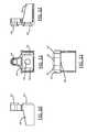
- FIG. 1is a perspective view of the cord and plug, showing the internals of the plug, according to an embodiment of the present invention.
- FIG. 2is a side elevation view of the cord and plug, according to an embodiment of the present invention.
- FIG. 3a rear elevation view of the cord entering the plug, according to an embodiment of the present invention.
- FIG. 4is a perspective view of a bracket, according to an embodiment of the present invention.
- FIG. 5is a front elevation view of the bracket of FIG. 4
- FIG. 6is a side elevation view of a bracket, according to an embodiment of the present invention.
- FIG. 7is a rear elevation view of the bracket of FIG. 6 .
- FIG. 8is a side elevation view of the bracket of FIG. 6
- FIG. 9is a top plan view of the bracket of FIG. 6 .
- FIG. 10is a side elevation view of a bracket, according to an embodiment of the present invention.
- FIG. 11is a rear elevation view of the bracket of FIG. 10 .
- FIG. 12is a side elevation view of the bracket of FIG. 10 .
- FIG. 13is a top plan view of the bracket of FIG. 10 .
- FIG. 14is a perspective view of a brace, according to an embodiment of the present invention.
- FIG. 15is a side elevation view of the brace of FIG. 14 .
- FIG. 16is a top plan view of the brace of FIG. 14 .
- FIG. 17is a side elevation view of the brace of FIG. 14 .
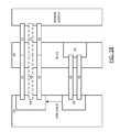
- FIG. 18is a block diagram illustrating a connective structure of the device, according to an embodiment of the present invention.
- FIG. 19is a flowchart of the operation of the system, according to an embodiment of the present invention.
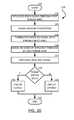
- FIG. 20is a flowchart of using a signal to control operation of the system, according to an embodiment of the present invention.
- the devicemay include a cord 40 , plug 30 , transmission wires 42 , sensor wires, a thermistor 20 or other sensor, and a switching device.
- the cord 40may include the transmission wires 42 and the sensor wires 46 , 48 .
- the cord 40may also include a ground wire 44 .
- the transmission wires 42may connect to prongs 32 , which may be included by the plug 30 .
- a ground prong 44may also be included by the plug 30 .
- the signal wiresmay connect to a thermistor 20 or other sensor, which may also be included by the plug 30 .
- the cord 40may be connected to an electrical device or appliance, generally referred to as an “appliance” without limitation, at the end of the cord 40 opposite to the plug 30 .
- an appliancean electrical device or appliance
- the switching devicemay be included by the appliance, which may open or close an electrical circuit respective to a signal received via a sensor wire. Alternatively, the switching device may be included in the plug 30 or cord 40 .
- the plug 30may include multiple components and connections that allow electrical power to be received from a power source and transmitted through the cord 40 . Skilled artisans will appreciate that power may be transmitted in either direction through the cord 40 , and should not view any examples of power being drawn from the plug 30 , through the cord 40 , and to an appliance, as limiting in any way.
- the plug 30may be inserted into an electrical outlet, from which it may draw power to be transmitted via the attached cord 40 .
- the plug 30may include prongs 32 .
- the prongs 32may be elongated members that are capable of being inserted into an electric receptacle, closing an electrical circuit and allowing the transmission of electrical power.
- a ground prong 34may also be included, which may allow an overflow of current to be transmitted to a grounded circuit, such as an earth ground. Skilled artisans understand and appreciate the composition of prongs 32 and ground prongs 34 in an electrical plug 30 .
- Transmission wires 42may be operatively connected to the prongs 32 to allow electricity to pass from the prongs 32 to the transmission wire 42 .
- Skilled artisanswill appreciate that any number of transmission wires 42 may be used and will not view the illustration of two transmission wires 42 to limit the present invention in any way.
- one or more ground wire 44may be connected to the ground prong 34 . Inclusion of ground wires 44 and the ground prong 34 may be optional.
- a sensorsuch as a thermistor 20
- a thermistor 20is an electronic component that possesses resistance characteristics that vary with respect to changes in its body temperature. Operation of a thermistor 20 will be discussed in greater detail below.
- One or more sensor wiresmay be connected to the thermistor 20 . In the embodiment illustrated in FIGS. 1 and 3 , two sensor wires are included in the device. Skilled artisans will appreciate that sensory of a condition, such as temperature, can be performed with more or less sensor wires, and should not view the present invention to be limited to two-sensor-wire systems.
- the prongs 32 , thermistor 20 , and other components of the plug 30may be connected to and/or supported by a bracket 36 , embodiments of which are perhaps best illustrated additionally in FIGS. 4-13 .
- the bracket 36may then be covered by an insulating shield to form the plug 30 .
- a brace 38may be included to position or maintain a location of the thermistor 20 within the plug 30 .
- the bracket 36will now be discussed in greater detail.
- the bracket 36may include a number of prong slots 62 , through which the prongs 32 may be passed.
- the prong slots 62may be shaped to accommodate and receive the prongs 32 .
- the bracket 36may also include a ground prong slot 64 .
- the ground prong slot 64may be shaped to accommodate and receive the ground prong 34 . Skilled artisans will appreciate additional slots that may be included in the bracket 36 consistent with this disclosure.
- the bracket 36may also include a thermistor dock 66 .
- the thermistor dock 66may be substantially opened on one end, but closed from exposure through the face of the bracket 36 at the opposite end.
- the thermistor dock 66may be shaped to receive a thermistor 20 .
- the thermistor dock 66may be shaped to snugly receive the thermistor 20 , at least partially securing the thermistor 20 in place.
- the thermistor 20may be additionally secured by adhesives, fixtures, or a brace 38 .
- the brace 38will be discussed in greater detail below.
- the bracket 36may be configured to receive various types of thermistors 20 and/or other sensors.
- FIGS. 6-9illustrate a bracket 36 configured to receive a thermistor 20 formed of heat conductive plastics.
- FIGS. 10-13illustrate a bracket 36 configured to receive a thermistor 20 formed of ceramics.
- Skilled artisanswill appreciate additional brackets 36 that may be adapted to receive additional sensors, which may include thermistors 20 with a combination of the aforementioned and/or alternative compositions, or other types of sensors.
- the brace 38may include one or more prong slot 62 , through which prongs 32 may be passed.
- the brace 38may also include a thermistor slot 68 , through which a thermistor 20 may be passed and/or secured.
- the brace 38may include a ground prong slot 64 , through which a ground prong 34 may be passed.
- the brace 38may work in concert with the bracket 36 to help secure one or more components of the plug 30 .
- the brace 38may be placed behind the inner face of the bracket 36 .
- the thermistor 20may be passed through the thermistor slot 68 of the brace 38 , such that it may be received by the thermistor dock 66 of the bracket 36 .
- the prongs 32may be passed through the prong slots 62 of the brace 38 and the prong slots 62 of the bracket 36 , helping to keep the thermistor 20 spaced at a desired distance between the prongs 32 .
- Skilled artisanswill appreciate additional configurations by which the brace 38 may be included in the plug 30 that would be apparent after having the benefit of this disclosure.
- the brace 38may be secured by adhesives, fixtures, or other securing techniques.
- the cord 40may include transmission wires 42 , sensor wires 46 , 48 , and optionally ground wires 44 .
- the cord 40may also include insulation, shielding, and other elements typical to an electrical power cord 40 , as will be appreciated by those of skill in the art.
- the cord 40may also include other types of wires that would be apparent to skilled artisans.
- An insulator or other materialmay enclose the transmission wires 42 , sensor wires, and optionally ground wires 44 carried by the cord 40 . In an embodiment, the insulating material may approximately uniformly encircle and enclose the wires carried by the cord 40 .
- the transmission wires 42may carry electrical power from the plug 30 to the appliance.
- the transmission wires 42may be configured with a width or gauge adequate to carry an electrical current required to drive the connected appliance.
- the sensor wiresmay carry a signal, which may be used or analyzed to reflect a condition in the cord 40 .
- the sensor wiresmay connect to the appliance, which may include a sensing device and/or switching device, at a first end of the cord 40 .
- the sensor wiresmay also connect to the thermistor 20 , which may be located in the plug 30 at the opposite end of the cord 40 .
- the thermistor 20may vary the signal transmitted by the sensor wires.
- the signalmay be used to directly or indirectly open or close a circuit. The operation by which the circuit may be controlled will be discussed in greater detail below.
- At least two sensor wiresare included in the cord 40 , a first sensor wire 46 and a second sensor wire 48 .
- the signalmay pass from the appliance or sensing device to the thermistor 20 via the first sensor wire 46 .
- the thermistor 20may then vary the signal received from the first sensor wire 46 .
- the signalmay then pass from the thermistor 20 back to the appliance via the second sensor wire 48 .
- Skilled artisansshould not view this two-sensor-wire embodiment to limit the present invention in any way.
- the sensorwill now be discussed in greater detail.
- the sensorwill be discussed as being a thermistor.
- Skilled artisanswill appreciate additional sensors that may be included in the cord 40 and/or plug 30 to detect a condition and vary a signal accordingly.
- the conditionmay be, but should not be limited to, change in temperature or heat. Accordingly, the following example should not be read to limit the present invention.
- a thermistor 20is a component used in electrical circuits that vary resistance in relation to change in temperature.
- the general workings of a thermistorshould be appreciated by those with skill in the art.
- the resistance variation of a thermistoris typically higher than with standard resistors.
- Thermistorsare typically created using a ceramic and/or polymer, such as a high thermal plastic. Thermistors may also be created using semiconductor materials.
- Oxidesmay be added to the thermistor material, which may be combined as a powder with a binding compound.
- oxidesthat may be used in creating a thermistor include, but should not be limited to, manganese, cobalt, nickel, iron, copper, titanium, a combination of multiple oxides, or other similar materials.
- Other thermistorsmay include compositions of barium titanate, lead, strontium titanates, yttrium, manganese, and/or silica. The quantity and configuration of these materials may determine the thermal and resistive characteristics of the thermistor.
- thermistor 20may operate with a positive temperature coefficient (PTC) or negative temperature coefficient (NTC).
- PTCpositive temperature coefficient
- NTCnegative temperature coefficient
- thermistorsthat include compositions of barium titanate, lead, strontium titanate, yttrium, manganese, and/or silica have positive temperature coefficients.
- thermistors that include metal oxides of manganese, nickel, cobalt, copper, and/or ironhave a negative temperature coefficient. In applications other than small temperature changes, the rate of increase and decrease of resistance compared to change in temperature is often non-linear.
- Sensing temperature using a thermistor 20will now be discussed. More specifically, sensing temperature using a NTC thermistor 20 will now be discussed.
- the resistive characteristics of a NTC thermistor 20vary indirectly with its temperature. For example, as the temperature of a NTC thermistor 20 may increase, the resistive properties of the thermistor 20 may decrease. This decrease in resistance may allow an electrical signal to pass through the thermistor 20 without being substantially varied by resistance from the thermistor 20 .
- Wiresmay be connected to the thermistor 20 , such as sensor wires, to conduct an electrical signal to and from the thermistor 20 .
- the resistance of the sensor wireswill be low, and thus may have a negligible impact on the resistance applied to the sensory signal compared to the thermistor 20 .
- the sensor wires connected to the thermistor 20may also be connected to a sensing device at their opposite ends.
- the sensing devicemay detect a level of resistance applied to an electrical signal.
- the electrical signalmay be a voltage, such as a direct current (DC) voltage. Additionally, the electrical signal may include a waveform and/or data transmission.
- the sensing devicemay detect the signal, and a resistance applied to the same, from one or more of the sensor wires. Upon detecting the signal, the sensing device may analyze the signal to determine the temperature of the device, as detected by the thermistor 20 .
- the sensing devicemay determine the change in temperature at the plug 30 , which has been detected by a NTC thermistor 20 in the plug 30 , by detecting a drop in resistance to the electrical signal carried by the sensor wires.
- the sensing device and/or the switching devicemay be configured to open or close the power circuit, or the circuit through which power is transmitted to from the plug 30 to the appliance via the transmission wires 42 , according to the signal detected by the sensor wires.
- the sensing devicemay actively or passively control the circuit.
- programmable logicmay be implemented by the sensing device to define voltage or signal thresholds at which the device should open or close the circuit.
- passive systemsmay include components that are engaged upon a condition being met, such as a voltage threshold, which may be defined by a threshold resistance.
- the power circuitmay be opened or closed in response to the signal detected from the sensor wires.
- the power circuitmight use an electrically operated switching device, such as a relay or triac.
- a relaymay be used to control the power circuit by receiving a low-power signal and opening or closing the power circuit responsive to the characteristic of the low-power signal.
- the low-power signalmay be received directly from the signal wire and/or an analog circuit connected to the signal wire.
- the low-power signal used to active the switching devicemay be generated by digital logic connected to the signal wire.
- the sensing devicemay be included in an appliance, which may be connected at least in part to the cord 40 .
- the sensing devicemay be included in the plug 30 or within the cord 40 .
- Skilled artisanswill appreciate a plethora of locations at which the sensory device may be located while maintaining the ability to detect a level of resistance across sensor wires and affect an electrical power circuit.
- Block diagram 50illustrates a power source 54 , which may supply power to a connected device or appliance 56 .
- the power source 54may be, for example, a common electrical outlet.
- the plug 30may interface with the power source 54 .
- two prongs 32may be used to connect the plug 30 to the power source 54 .
- a ground prong 34may also connect between the plug 30 and the power source 54 .
- the prongs 32may be connected to the transmission wires 42 . In configurations that include a ground wire 44 and/or ground prong 34 , a connection between the two may also be made in the plug 30 . Additionally, the plug 30 may include a thermistor 20 . A number of sensor wires may be connected to the thermistor 20 in the plug 30 . In the example illustrated by block diagram 50 , two sensor wires are connected to the thermistor 20 in the plug 30 . These two sensor wires include a first sensor wire 46 and a second sensor wire 48 .
- the transmission wires 42 , sensor wires 46 , 48 , and optional ground wire 44may be carried together in the cord 40 to an appliance 56 .
- Skilled artisanswill appreciate that one or more of the wires may be carried in separate, collective, or otherwise configured cords 40 . As such, the present invention should not be limited to embodiments that only include one cord 40 . Similarly, the present invention should not be limited to embodiments with cords 40 having only one plug 30 and one appliance 56 .
- the cord 40and the wires carried by the cord 40 , may be connected to an appliance 56 .
- the sensor wires 46 , 48may be connected to a sensing device 58 , which may be included in the appliance 56 .
- the transmission wires 42may be connected to a switching device 59 . If included, the ground wire 44 may also be connected to the switching device 59 or directly to the appliance 56 .
- the sensing device 58may also be connected to the switching device 59 , allowing the sensing device 58 to control the switching device 59 . As discussed above, in some embodiments, the sensor wires may be connected to the switching device 59 directly. From the switching device 59 , the transmission wires 42 may be connected to deliver electrical power to the appliance 56 .
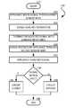
- the devicemay detect the temperature of an environment, such as the plug 30 or cord 40 (Block 104 ). As discussed above, the temperature may be detected by the thermistor 20 located in the plug 30 . The device may then determine whether the temperature is above a limit (Block 106 ). The limit may be a predefined or variably defined temperature at which the device may desirably operate. If it is determined at Block 106 that the temperature is not above the limit, the electrical circuit may be closed or remain closed and electrical power may be provided to the appliance (Block 108 ).
- the electrical circuitmay be opened or remain opened and electrical power may not be provided to the appliance (Block 110 ). After the circuit has been set or maintained to be opened or closed, the operation may then terminate at Block 112 . Skilled artisans will appreciate that the operation illustrated by flowchart 100 may occur substantially continuously.
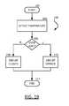
- the appliancemay send a signal to the thermistor 20 through the first signal wire 46 (Block 124 ).
- This signalmay be a constant voltage, a waveform, and/or a signal containing data.
- the signalmay then reach the thermistor 20 (Block 126 ).
- the thermistor 20may modify the signal with a variable resistance (Block 128 ). As discussed above, the resistance provided by the thermistor 20 may vary with respect to the temperature sensed by the thermistor 20 .
- the signalmay be received by the appliance from the thermistor 20 through the second signal wire 48 (Block 130 ).
- the appliancemay then analyze the signal at Block 132 .
- the analysismay be active or passive, without limitation. Additionally, analysis of the signal may be performed by a sensing device, which may be included in the appliance.
- the appliancemay determine whether the signal is within an acceptable specification at Block 134 . Compliance with the acceptable specification may be analyzed by comparing the signal to a threshold voltage, which may be affected by a threshold resistance of the thermistor 20 . If it is determined at Block 134 that the signal is within an acceptable specification, the electrical circuit may be closed or remain closed and electrical power may be provided to the appliance (Block 136 ). Conversely, if it is determined at Block 134 that the temperature is not within an acceptable specification, the electrical circuit may be opened or remain opened and electrical power may be not provided to the appliance (Block 138 ). After the circuit has been set or maintained to be opened or closed, the operation may then terminate at Block 140 . Skilled artisans will appreciate that the operation illustrated by flowchart 120 may occur substantially continuously.
Landscapes
- Details Of Connecting Devices For Male And Female Coupling (AREA)
- Protection Of Static Devices (AREA)
- Thermistors And Varistors (AREA)
Abstract
Description
Claims (20)
Priority Applications (5)
| Application Number | Priority Date | Filing Date | Title |
|---|---|---|---|
| US13/707,405US9787083B2 (en) | 2012-12-06 | 2012-12-06 | Overheat-resistant power cord and method |
| CN201310088663.9ACN103855551A (en) | 2012-12-06 | 2013-03-19 | Overheat-Resistant Power Cord and Method |
| JP2013165958AJP2014117142A (en) | 2012-12-06 | 2013-08-09 | Overheating-proof power supply code and method |
| MX2013012875AMX2013012875A (en) | 2012-12-06 | 2013-11-04 | Overheat-resistant power cord and method. |
| CA2833097ACA2833097C (en) | 2012-12-06 | 2013-11-12 | Overheat-resistant power cord and method |
Applications Claiming Priority (1)
| Application Number | Priority Date | Filing Date | Title |
|---|---|---|---|
| US13/707,405US9787083B2 (en) | 2012-12-06 | 2012-12-06 | Overheat-resistant power cord and method |
Publications (2)
| Publication Number | Publication Date |
|---|---|
| US20140160611A1 US20140160611A1 (en) | 2014-06-12 |
| US9787083B2true US9787083B2 (en) | 2017-10-10 |
Family
ID=50862899
Family Applications (1)
| Application Number | Title | Priority Date | Filing Date |
|---|---|---|---|
| US13/707,405Active2033-06-02US9787083B2 (en) | 2012-12-06 | 2012-12-06 | Overheat-resistant power cord and method |
Country Status (5)
| Country | Link |
|---|---|
| US (1) | US9787083B2 (en) |
| JP (1) | JP2014117142A (en) |
| CN (1) | CN103855551A (en) |
| CA (1) | CA2833097C (en) |
| MX (1) | MX2013012875A (en) |
Cited By (1)
| Publication number | Priority date | Publication date | Assignee | Title |
|---|---|---|---|---|
| US10871403B1 (en)* | 2019-09-23 | 2020-12-22 | Kidde Technologies, Inc. | Aircraft temperature sensor |
Families Citing this family (19)
| Publication number | Priority date | Publication date | Assignee | Title |
|---|---|---|---|---|
| KR101549626B1 (en)* | 2013-12-20 | 2015-09-03 | (주)엠에스테크비젼 | Charge cable |
| JP6295887B2 (en)* | 2014-08-22 | 2018-03-20 | ミツミ電機株式会社 | Cable with plug and control circuit and board |
| DE102014012576A1 (en)* | 2014-08-29 | 2016-03-03 | Heidelberger Druckmaschinen Ag | Injector plug in layered construction for electric cars |
| TWI548169B (en)* | 2014-10-09 | 2016-09-01 | 勝德國際研發股份有限公司 | Power extension wire |
| US9837791B1 (en)* | 2016-06-03 | 2017-12-05 | Nlight, Inc. | Multifunctional circuit for monitoring fiber cable health |
| US10329828B2 (en)* | 2016-10-13 | 2019-06-25 | Harpal C Singh | Smart management system for garage doors and electronic devices |
| JP6908387B2 (en)* | 2017-02-10 | 2021-07-28 | 株式会社マキタ | Power adapter |
| CN109787042B (en)* | 2017-11-13 | 2021-07-23 | 台达电子工业股份有限公司 | electrical connector |
| KR102659809B1 (en)* | 2018-03-19 | 2024-04-23 | 리텔퓨즈 인코퍼레이티드 | Usb cable with thermal protection |
| JP7033762B2 (en)* | 2018-03-30 | 2022-03-11 | パナソニックIpマネジメント株式会社 | How to prevent overheating of outlets and outlets |
| CN108387006A (en)* | 2018-04-24 | 2018-08-10 | 余姚市嘉荣电子电器有限公司 | A kind of water heater leakage protection system of double-direction control |
| CN108375196B (en)* | 2018-04-24 | 2024-03-19 | 余姚市嘉荣电子电器有限公司 | Leakage protection system for water outlet power failure |
| CN109167190A (en)* | 2018-08-01 | 2019-01-08 | 余姚市嘉荣电子电器有限公司 | A kind of manufacturing method of temp-control plug |
| CN109361095B (en)* | 2018-10-10 | 2023-10-20 | 余姚市嘉荣电子电器有限公司 | High-sensitivity thermistor safety plug |
| US11506541B2 (en)* | 2019-01-03 | 2022-11-22 | Aptiv Technologies Limited | Temperature monitoring device |
| CN112763092B (en)* | 2021-01-08 | 2025-02-07 | 维尔斯电子(昆山)有限公司 | Thermistor Test System |
| CN115313110B (en)* | 2021-05-07 | 2025-06-24 | 台达电子工业股份有限公司 | plug |
| CN116417829A (en)* | 2021-12-30 | 2023-07-11 | 深圳市和生创新技术有限公司 | Power line temperature detection and protection system and method, and temperature detection and control device |
| AU2024266119A1 (en)* | 2023-05-04 | 2025-10-09 | Simaan HAKIM | Electrical safety devices and apparatuses for preventing flow of electric current based on temperature sensing |
Citations (61)
| Publication number | Priority date | Publication date | Assignee | Title |
|---|---|---|---|---|
| DE1942110A1 (en) | 1969-08-19 | 1971-03-04 | Kabel Metallwerke Ghh | Thermal monitoring of power cables |
| NL7506090A (en) | 1975-05-23 | 1976-11-25 | Koninkl Metaalfab Daalderop B | EQUIPMENT CONTACT STOP. |
| US4310837A (en) | 1980-10-14 | 1982-01-12 | General Electric Company | Electrical device termination high temperature indicator |
| US4389694A (en) | 1980-10-08 | 1983-06-21 | Pemco Corporation | Cable continuity monitoring system |
| US4470711A (en) | 1983-03-30 | 1984-09-11 | General Electric Company | Electrical device termination high temperature indicator |
| US4707686A (en) | 1986-04-03 | 1987-11-17 | General Electric Company | Over temperature sensing system for power cables |
| JPH01298917A (en) | 1988-05-27 | 1989-12-01 | Fujita Corp | Power supply equipment monitoring method and power supply equipment monitoring device |
| DE3900606A1 (en) | 1989-01-11 | 1990-07-12 | Asea Brown Boveri | Protection of electrical cables (leads, lines) against excessive heating |
| US5003486A (en) | 1989-02-24 | 1991-03-26 | Nero Technologies Ltd. | Programmable safety electrical socket controller |
| US5188542A (en) | 1991-12-05 | 1993-02-23 | Gray Ballman | Electrical connector with integral strain relief and mount, and overtemperature indicator |
| US5250892A (en) | 1991-04-05 | 1993-10-05 | Yang Tai Her | Battery charge with temperature-sensitive cut-off switch |
| US5424895A (en) | 1993-08-17 | 1995-06-13 | Gaston; William R. | Electrical wiring system with overtemperature protection |
| CN1134092A (en) | 1995-04-18 | 1996-10-23 | 平和电子 | Remote controlling pager |
| DE19602631C1 (en) | 1996-01-25 | 1997-02-13 | Lauerer Friedrich | Electrical protection device |
| US5633775A (en) | 1996-05-14 | 1997-05-27 | Scarelli; David F. | Fire sentry power cable |
| US5833489A (en) | 1995-12-29 | 1998-11-10 | Daewoo Electronics Co., Ltd. | Electrical plug |
| US5841617A (en) | 1997-04-07 | 1998-11-24 | Bpw, Inc. | Electrical safety device with conductive polymer sensor |
| US5844759A (en)* | 1995-05-26 | 1998-12-01 | David C. Nemir | Electrical fault interrupter |
| JPH10326646A (en) | 1996-11-20 | 1998-12-08 | Sumitomo Electric Ind Ltd | Power plug with shut-off function |
| CA2240119A1 (en) | 1997-06-11 | 1998-12-11 | Leviton Manufacturing Co., Inc. | Over-temperature sensor cable and electrical cord with over-temperature protection |
| US5946180A (en) | 1998-08-26 | 1999-08-31 | Ofi Inc. | Electrical connection safety apparatus and method |
| US5995350A (en) | 1998-06-24 | 1999-11-30 | Kopelman; Robert Z. | Temperature controlled circuit interrupter |
| US20020121983A1 (en) | 1992-07-01 | 2002-09-05 | David Boyden | Alarm system for detecting excess temperature in electrical wiring |
| WO2003000324A1 (en) | 2001-06-25 | 2003-01-03 | Tostop Ab | Device and method for the administration of a substance |
| GB2388977A (en) | 2002-05-24 | 2003-11-26 | Fung Yip Electrical Mfg Ltd | A load overcurrent alarm device and a connector overheat alarm device |
| KR20030096543A (en) | 2002-06-14 | 2003-12-31 | 주식회사 위닉스 | Power plug |
| US20040169969A1 (en) | 2001-09-11 | 2004-09-02 | Hideaki Takeda | Safety device |
| US6801117B2 (en) | 1997-12-10 | 2004-10-05 | B.P.W., Inc. | Fault sensing wire and alarm apparatus |
| US6893153B2 (en) | 2002-06-28 | 2005-05-17 | Hewlett-Packard Development Company, L.P. | Temperature-indicating power adapter and electronic device that operates therewith |
| US20050109752A1 (en)* | 2002-03-14 | 2005-05-26 | Ernst Merk | Heating device with flexible heating body |
| FR2880728A1 (en) | 2005-01-13 | 2006-07-14 | Eric Goetsch | Electric installation e.g. movable plug, protecting device, has deformable maintaining unit arranged for deforming itself under effect of temperature rise in order to permit movable contact unit to contact connecting unit |
| WO2006109330A1 (en) | 2005-04-13 | 2006-10-19 | Kem-O-Tek Italia Srl | Electronic connector protecting method |
| US20080057780A1 (en)* | 2006-08-10 | 2008-03-06 | O'rourke Kevin | Adjustable anchor for extension cord |
| US20080056331A1 (en)* | 2004-09-30 | 2008-03-06 | Matias Javier A | Sensor Device |
| US20080080592A1 (en)* | 2006-07-21 | 2008-04-03 | Hans Houben | Temperature sensor for a resistance thermometer, in particular for use in the exhaust gas system of combustion engines |
| JP2008154305A (en) | 2006-12-14 | 2008-07-03 | Toyota Motor Corp | Cable protection mechanism |
| US7420792B2 (en) | 2005-08-16 | 2008-09-02 | Monolithic Power Systems, Inc. | Linear charger where the material temperature directly affects the circuit thermal control |
| US20090195237A1 (en)* | 2008-01-31 | 2009-08-06 | Feliss Norbert A | Dual direction power and data transfer protocol and safety detection |
| TW200937788A (en) | 2008-02-29 | 2009-09-01 | Chaun-Yuan Chen | An overheat safety protection of power supply socket when overloaded |
| US20100029140A1 (en)* | 2006-08-10 | 2010-02-04 | O'rourke Kevin | Swing Fastener For Securing 120V Electrical Connectors |
| US7737704B2 (en) | 2007-06-12 | 2010-06-15 | Broadcom Corporation | System and method for using a PHY to locate a thermal signature in a cable plant for diagnostic, enhanced, and higher power applications |
| US7801648B2 (en) | 2006-05-23 | 2010-09-21 | Hanbit Tech Inc. | Automatic trip device and control method thereof |
| CN201590647U (en) | 2009-11-23 | 2010-09-22 | 英业达股份有限公司 | Overheat protection circuit and power conversion device using same |
| JP2011014516A (en) | 2009-07-02 | 2011-01-20 | Izumi Shoji:Kk | Outlet with sensor |
| US7944667B2 (en) | 2008-06-18 | 2011-05-17 | GM Global Technology Operations LLC | Thermal security for hybrid vehicle recharging cable plugs device and method |
| US20110134575A1 (en)* | 2009-12-07 | 2011-06-09 | Ward Michael J | Heat sensor responsive to electrical overloads |
| TW201136081A (en) | 2010-04-01 | 2011-10-16 | Hon Hai Prec Ind Co Ltd | Electronic device having high temperature protection circuit |
| JP2012149059A (en) | 2010-12-27 | 2012-08-09 | Tosoh Corp | 1,3,5-triazine compound, method for preparing the same, and organic electroluminescent element including the compound as constituent componnt |
| US8248260B1 (en)* | 2009-07-20 | 2012-08-21 | Pope Ralph E | Electrical safety device for temperature control and mechanical damage |
| US20120287546A1 (en)* | 2011-05-10 | 2012-11-15 | Kopelman Robert Z | Sensor-activated circuit-interrupting apparatus and method of using same |
| US8325454B2 (en) | 2008-04-07 | 2012-12-04 | Technology Research Corporation | Over heating detection and interrupter circuit |
| US8339760B2 (en) | 2009-06-15 | 2012-12-25 | Apple Inc. | Thermal protection circuits and structures for electronic devices and cables |
| US8405946B2 (en) | 2007-11-19 | 2013-03-26 | Autonetworks Technologies, Ltd. | Wire protection method and wire protection device |
| US20130077222A1 (en)* | 2011-09-23 | 2013-03-28 | Infineon Technologies Ag | Power semiconductor module with wireless saw temperature sensor |
| RU127537U1 (en) | 2012-12-19 | 2013-04-27 | Открытое акционерное общество "Энера Инжиниринг" | DEVICE FOR AUTOMATIC RESTRICTION OF OVERLOADING OF A CABLE-AIR TRANSMISSION LINE |
| US8432657B2 (en) | 2008-03-28 | 2013-04-30 | Yazaki Corporation | Protection apparatus of load circuit |
| US8498087B2 (en) | 2009-11-03 | 2013-07-30 | Apple Inc. | Thermal protection circuits for electronic device cables |
| US20130342352A1 (en) | 2010-09-30 | 2013-12-26 | Gantel Properties Limited | System and Method for Fire Preventing in Electrical Installations |
| US20140045366A1 (en)* | 2006-08-10 | 2014-02-13 | Kevin O'Rourke | Electrical adaptor having a temperature indicator |
| US8693156B2 (en) | 2009-06-04 | 2014-04-08 | Yazaki Corporation | Protection apparatus for load circuit |
| US8740456B2 (en) | 2011-05-17 | 2014-06-03 | Smsc Holdings S.A.R.L. | Adjusting delivery of current in a connection based on temperature |
Family Cites Families (8)
| Publication number | Priority date | Publication date | Assignee | Title |
|---|---|---|---|---|
| JPS6437337U (en)* | 1987-08-28 | 1989-03-07 | ||
| JPH0767245A (en)* | 1993-08-27 | 1995-03-10 | Janome Sewing Mach Co Ltd | Safety unit for power supply circuit |
| JP2001218361A (en)* | 2000-02-07 | 2001-08-10 | Auto Network Gijutsu Kenkyusho:Kk | Overheat protection circuit |
| JP2002352635A (en)* | 2001-05-24 | 2002-12-06 | Hitachi Information Technology Co Ltd | Power cord with temperature sensor |
| CN2765344Y (en)* | 2004-12-30 | 2006-03-15 | 陆流 | A power plug with overheat protector |
| CN100517882C (en)* | 2006-01-10 | 2009-07-22 | 海尔集团公司 | Power plug with temperature monitoring function |
| JP4031026B1 (en)* | 2007-08-08 | 2008-01-09 | 富士電線工業株式会社 | Power cord |
| US8729856B2 (en)* | 2011-02-23 | 2014-05-20 | Lear Corporation | Thermal wall plug sensing and control |
- 2012
- 2012-12-06USUS13/707,405patent/US9787083B2/enactiveActive
- 2013
- 2013-03-19CNCN201310088663.9Apatent/CN103855551A/enactivePending
- 2013-08-09JPJP2013165958Apatent/JP2014117142A/enactivePending
- 2013-11-04MXMX2013012875Apatent/MX2013012875A/enunknown
- 2013-11-12CACA2833097Apatent/CA2833097C/enactiveActive
Patent Citations (63)
| Publication number | Priority date | Publication date | Assignee | Title |
|---|---|---|---|---|
| DE1942110A1 (en) | 1969-08-19 | 1971-03-04 | Kabel Metallwerke Ghh | Thermal monitoring of power cables |
| GB1280732A (en) | 1969-08-19 | 1972-07-05 | Kabel Metallwerke Ghh | Thermal monitoring of power cables |
| NL7506090A (en) | 1975-05-23 | 1976-11-25 | Koninkl Metaalfab Daalderop B | EQUIPMENT CONTACT STOP. |
| US4389694A (en) | 1980-10-08 | 1983-06-21 | Pemco Corporation | Cable continuity monitoring system |
| US4310837A (en) | 1980-10-14 | 1982-01-12 | General Electric Company | Electrical device termination high temperature indicator |
| US4470711A (en) | 1983-03-30 | 1984-09-11 | General Electric Company | Electrical device termination high temperature indicator |
| US4707686A (en) | 1986-04-03 | 1987-11-17 | General Electric Company | Over temperature sensing system for power cables |
| JPH01298917A (en) | 1988-05-27 | 1989-12-01 | Fujita Corp | Power supply equipment monitoring method and power supply equipment monitoring device |
| DE3900606A1 (en) | 1989-01-11 | 1990-07-12 | Asea Brown Boveri | Protection of electrical cables (leads, lines) against excessive heating |
| US5003486A (en) | 1989-02-24 | 1991-03-26 | Nero Technologies Ltd. | Programmable safety electrical socket controller |
| US5250892A (en) | 1991-04-05 | 1993-10-05 | Yang Tai Her | Battery charge with temperature-sensitive cut-off switch |
| US5188542A (en) | 1991-12-05 | 1993-02-23 | Gray Ballman | Electrical connector with integral strain relief and mount, and overtemperature indicator |
| US20020121983A1 (en) | 1992-07-01 | 2002-09-05 | David Boyden | Alarm system for detecting excess temperature in electrical wiring |
| US5424895A (en) | 1993-08-17 | 1995-06-13 | Gaston; William R. | Electrical wiring system with overtemperature protection |
| CN1134092A (en) | 1995-04-18 | 1996-10-23 | 平和电子 | Remote controlling pager |
| US5844759A (en)* | 1995-05-26 | 1998-12-01 | David C. Nemir | Electrical fault interrupter |
| US5833489A (en) | 1995-12-29 | 1998-11-10 | Daewoo Electronics Co., Ltd. | Electrical plug |
| DE19602631C1 (en) | 1996-01-25 | 1997-02-13 | Lauerer Friedrich | Electrical protection device |
| US5633775A (en) | 1996-05-14 | 1997-05-27 | Scarelli; David F. | Fire sentry power cable |
| JPH10326646A (en) | 1996-11-20 | 1998-12-08 | Sumitomo Electric Ind Ltd | Power plug with shut-off function |
| US5841617A (en) | 1997-04-07 | 1998-11-24 | Bpw, Inc. | Electrical safety device with conductive polymer sensor |
| CA2240119A1 (en) | 1997-06-11 | 1998-12-11 | Leviton Manufacturing Co., Inc. | Over-temperature sensor cable and electrical cord with over-temperature protection |
| US6801117B2 (en) | 1997-12-10 | 2004-10-05 | B.P.W., Inc. | Fault sensing wire and alarm apparatus |
| US5995350A (en) | 1998-06-24 | 1999-11-30 | Kopelman; Robert Z. | Temperature controlled circuit interrupter |
| US5946180A (en) | 1998-08-26 | 1999-08-31 | Ofi Inc. | Electrical connection safety apparatus and method |
| WO2003000324A1 (en) | 2001-06-25 | 2003-01-03 | Tostop Ab | Device and method for the administration of a substance |
| US20040169969A1 (en) | 2001-09-11 | 2004-09-02 | Hideaki Takeda | Safety device |
| US20050109752A1 (en)* | 2002-03-14 | 2005-05-26 | Ernst Merk | Heating device with flexible heating body |
| GB2388977A (en) | 2002-05-24 | 2003-11-26 | Fung Yip Electrical Mfg Ltd | A load overcurrent alarm device and a connector overheat alarm device |
| KR20030096543A (en) | 2002-06-14 | 2003-12-31 | 주식회사 위닉스 | Power plug |
| US6893153B2 (en) | 2002-06-28 | 2005-05-17 | Hewlett-Packard Development Company, L.P. | Temperature-indicating power adapter and electronic device that operates therewith |
| US20080056331A1 (en)* | 2004-09-30 | 2008-03-06 | Matias Javier A | Sensor Device |
| FR2880728A1 (en) | 2005-01-13 | 2006-07-14 | Eric Goetsch | Electric installation e.g. movable plug, protecting device, has deformable maintaining unit arranged for deforming itself under effect of temperature rise in order to permit movable contact unit to contact connecting unit |
| WO2006109330A1 (en) | 2005-04-13 | 2006-10-19 | Kem-O-Tek Italia Srl | Electronic connector protecting method |
| US7420792B2 (en) | 2005-08-16 | 2008-09-02 | Monolithic Power Systems, Inc. | Linear charger where the material temperature directly affects the circuit thermal control |
| US7801648B2 (en) | 2006-05-23 | 2010-09-21 | Hanbit Tech Inc. | Automatic trip device and control method thereof |
| US20080080592A1 (en)* | 2006-07-21 | 2008-04-03 | Hans Houben | Temperature sensor for a resistance thermometer, in particular for use in the exhaust gas system of combustion engines |
| US20080057780A1 (en)* | 2006-08-10 | 2008-03-06 | O'rourke Kevin | Adjustable anchor for extension cord |
| US20140045366A1 (en)* | 2006-08-10 | 2014-02-13 | Kevin O'Rourke | Electrical adaptor having a temperature indicator |
| US20100029140A1 (en)* | 2006-08-10 | 2010-02-04 | O'rourke Kevin | Swing Fastener For Securing 120V Electrical Connectors |
| JP2008154305A (en) | 2006-12-14 | 2008-07-03 | Toyota Motor Corp | Cable protection mechanism |
| US7737704B2 (en) | 2007-06-12 | 2010-06-15 | Broadcom Corporation | System and method for using a PHY to locate a thermal signature in a cable plant for diagnostic, enhanced, and higher power applications |
| US8405946B2 (en) | 2007-11-19 | 2013-03-26 | Autonetworks Technologies, Ltd. | Wire protection method and wire protection device |
| US20090195237A1 (en)* | 2008-01-31 | 2009-08-06 | Feliss Norbert A | Dual direction power and data transfer protocol and safety detection |
| TW200937788A (en) | 2008-02-29 | 2009-09-01 | Chaun-Yuan Chen | An overheat safety protection of power supply socket when overloaded |
| US8432657B2 (en) | 2008-03-28 | 2013-04-30 | Yazaki Corporation | Protection apparatus of load circuit |
| US8325454B2 (en) | 2008-04-07 | 2012-12-04 | Technology Research Corporation | Over heating detection and interrupter circuit |
| US7944667B2 (en) | 2008-06-18 | 2011-05-17 | GM Global Technology Operations LLC | Thermal security for hybrid vehicle recharging cable plugs device and method |
| US8693156B2 (en) | 2009-06-04 | 2014-04-08 | Yazaki Corporation | Protection apparatus for load circuit |
| US8339760B2 (en) | 2009-06-15 | 2012-12-25 | Apple Inc. | Thermal protection circuits and structures for electronic devices and cables |
| JP2011014516A (en) | 2009-07-02 | 2011-01-20 | Izumi Shoji:Kk | Outlet with sensor |
| US8248260B1 (en)* | 2009-07-20 | 2012-08-21 | Pope Ralph E | Electrical safety device for temperature control and mechanical damage |
| US8498087B2 (en) | 2009-11-03 | 2013-07-30 | Apple Inc. | Thermal protection circuits for electronic device cables |
| CN201590647U (en) | 2009-11-23 | 2010-09-22 | 英业达股份有限公司 | Overheat protection circuit and power conversion device using same |
| US20110134575A1 (en)* | 2009-12-07 | 2011-06-09 | Ward Michael J | Heat sensor responsive to electrical overloads |
| US8605402B2 (en) | 2009-12-07 | 2013-12-10 | Michael J. Ward | Heat sensor responsive to electrical overloads |
| TW201136081A (en) | 2010-04-01 | 2011-10-16 | Hon Hai Prec Ind Co Ltd | Electronic device having high temperature protection circuit |
| US20130342352A1 (en) | 2010-09-30 | 2013-12-26 | Gantel Properties Limited | System and Method for Fire Preventing in Electrical Installations |
| JP2012149059A (en) | 2010-12-27 | 2012-08-09 | Tosoh Corp | 1,3,5-triazine compound, method for preparing the same, and organic electroluminescent element including the compound as constituent componnt |
| US20120287546A1 (en)* | 2011-05-10 | 2012-11-15 | Kopelman Robert Z | Sensor-activated circuit-interrupting apparatus and method of using same |
| US8740456B2 (en) | 2011-05-17 | 2014-06-03 | Smsc Holdings S.A.R.L. | Adjusting delivery of current in a connection based on temperature |
| US20130077222A1 (en)* | 2011-09-23 | 2013-03-28 | Infineon Technologies Ag | Power semiconductor module with wireless saw temperature sensor |
| RU127537U1 (en) | 2012-12-19 | 2013-04-27 | Открытое акционерное общество "Энера Инжиниринг" | DEVICE FOR AUTOMATIC RESTRICTION OF OVERLOADING OF A CABLE-AIR TRANSMISSION LINE |
Cited By (1)
| Publication number | Priority date | Publication date | Assignee | Title |
|---|---|---|---|---|
| US10871403B1 (en)* | 2019-09-23 | 2020-12-22 | Kidde Technologies, Inc. | Aircraft temperature sensor |
Also Published As
| Publication number | Publication date |
|---|---|
| JP2014117142A (en) | 2014-06-26 |
| CA2833097A1 (en) | 2014-06-06 |
| US20140160611A1 (en) | 2014-06-12 |
| MX2013012875A (en) | 2014-06-23 |
| CA2833097C (en) | 2019-09-10 |
| CN103855551A (en) | 2014-06-11 |
Similar Documents
| Publication | Publication Date | Title |
|---|---|---|
| US9787083B2 (en) | Overheat-resistant power cord and method | |
| EP3770936B1 (en) | Hybrid air-gap / solid-state circuit breaker | |
| US7813091B2 (en) | Leakage current detector interrupter with continuous duty relay | |
| IL273917B1 (en) | Digital power distribution system with non-linear load | |
| TW201249047A (en) | Integrated overdrive and overvoltage protection device | |
| CA2286359A1 (en) | Electrical safety device with conductive polymer sensor | |
| CN105337252B (en) | Earth leakage protective device with self-checking function | |
| JP2002352635A (en) | Power cord with temperature sensor | |
| US9634481B2 (en) | MOSFET protection using resistor-capacitor thermal network | |
| US10333294B2 (en) | USB cable with thermal protection | |
| CN105449635B (en) | Earth leakage protective device with over-temperature protection device | |
| CN109390919B (en) | Digital line protection | |
| US11901722B2 (en) | Systems and methods for verifying and de-energizing circuit protection devices | |
| EP3544134B1 (en) | Usb cable with thermal protection | |
| US10389106B2 (en) | USB cable with thermal protection | |
| CN203932973U (en) | Earth leakage protective device | |
| US8724283B1 (en) | A.C. power line surge protectors | |
| RU2336417C1 (en) | Method of intrinsic safety provision for portable instruments | |
| KR101706330B1 (en) | The device to break the loading circuit of an low electric power device by Hall sensor when the over current introduces into the loading circuit | |
| KR101027136B1 (en) | Overcurrent breaking device and method using leakage current generator and earth leakage breaker | |
| US20060170428A1 (en) | Electrical safety cord | |
| KR20050008036A (en) | Plug for electrical products | |
| RU174735U1 (en) | OVERHEATING CONTACT CONTACTS FOR PLUGGING CONTACTS | |
| KR102092236B1 (en) | Wireless charging device and heating system including the same | |
| KR200330215Y1 (en) | Plug for electrical products |
Legal Events
| Date | Code | Title | Description |
|---|---|---|---|
| AS | Assignment | Owner name:TWIN-STAR INTERNATIONAL, INC., FLORIDA Free format text:ASSIGNMENT OF ASSIGNORS INTEREST;ASSIGNORS:CROWE, MATTHEW;LAM, FUNG U.;WU, YONG;SIGNING DATES FROM 20130404 TO 20130405;REEL/FRAME:030158/0882 | |
| AS | Assignment | Owner name:MONROE CAPITAL MANAGEMENT ADVISORS, LLC, AS AGENT, Free format text:SECURITY AGREEMENT;ASSIGNORS:TWIN-STAR INTERNATIONAL, INC.;BELL'O INTERNATIONAL CORP.;REEL/FRAME:038513/0252 Effective date:20160425 Owner name:MONROE CAPITAL MANAGEMENT ADVISORS, LLC, AS AGENT, ILLINOIS Free format text:SECURITY AGREEMENT;ASSIGNORS:TWIN-STAR INTERNATIONAL, INC.;BELL'O INTERNATIONAL CORP.;REEL/FRAME:038513/0252 Effective date:20160425 | |
| AS | Assignment | Owner name:BANK OF AMERICA, N.A., GEORGIA Free format text:SECURITY INTEREST;ASSIGNORS:TWIN-STAR INTERNATIONAL, INC.;BELL'O INTERNATIONAL CORP.;REEL/FRAME:038710/0823 Effective date:20160425 | |
| STCF | Information on status: patent grant | Free format text:PATENTED CASE | |
| AS | Assignment | Owner name:BELL'O INTERNATIONAL CORP., FLORIDA Free format text:RELEASE BY SECURED PARTY;ASSIGNOR:MONROE CAPITAL MANAGEMENT ADVISORS, LLC, AS AGENT;REEL/FRAME:051627/0834 Effective date:20200116 Owner name:TWINSTAR INTERNATIONAL, INC., FLORIDA Free format text:RELEASE BY SECURED PARTY;ASSIGNOR:MONROE CAPITAL MANAGEMENT ADVISORS, LLC, AS AGENT;REEL/FRAME:051627/0834 Effective date:20200116 | |
| AS | Assignment | Owner name:KAYNE SENIOR CREDIT IV LOANCO, LLC, AS ADMINISTRATIVE AGENT, ILLINOIS Free format text:SECURITY INTEREST;ASSIGNOR:TWIN-STAR INTERNATIONAL, INC.;REEL/FRAME:051698/0983 Effective date:20200124 | |
| AS | Assignment | Owner name:TWINSTAR INTERNATIONAL, INC., FLORIDA Free format text:RELEASE BY SECURED PARTY;ASSIGNOR:BANK OF AMERICA, N.A.;REEL/FRAME:051721/0777 Effective date:20200124 Owner name:BELL'O INTERNATIONAL CORP., FLORIDA Free format text:RELEASE BY SECURED PARTY;ASSIGNOR:BANK OF AMERICA, N.A.;REEL/FRAME:051721/0777 Effective date:20200124 | |
| MAFP | Maintenance fee payment | Free format text:PAYMENT OF MAINTENANCE FEE, 4TH YR, SMALL ENTITY (ORIGINAL EVENT CODE: M2551); ENTITY STATUS OF PATENT OWNER: SMALL ENTITY Year of fee payment:4 | |
| AS | Assignment | Owner name:KAYNE SENIOR CREDIT IV LOANCO, LLC, AS ADMINISTRATIVE AGENT, ILLINOIS Free format text:SECURITY INTEREST;ASSIGNOR:TWIN-STAR INTERNATIONAL, INC.;REEL/FRAME:056675/0450 Effective date:20210618 Owner name:PNC BANK, NATIONAL ASSOCIATION, PENNSYLVANIA Free format text:SECURITY INTEREST;ASSIGNOR:TWIN-STAR INTERNATIONAL, INC.;REEL/FRAME:056676/0253 Effective date:20210618 | |
| AS | Assignment | Owner name:TIGER FINANCE, LLC, MASSACHUSETTS Free format text:ASSIGNMENT OF INTELLECTUAL PROPERTY SECURITY AGREEMENT;ASSIGNOR:PNC BANK, NATIONAL ASSOCIATION;REEL/FRAME:070706/0162 Effective date:20250331 | |
| MAFP | Maintenance fee payment | Free format text:PAYMENT OF MAINTENANCE FEE, 8TH YR, SMALL ENTITY (ORIGINAL EVENT CODE: M2552); ENTITY STATUS OF PATENT OWNER: SMALL ENTITY Year of fee payment:8 |